Embed Size (px)
Citation preview

Graduation Project
Automatic Dual Axis Solar Tracking SystemSubmitted to:
An-Najah National UniversityIn partial fulfillment of the requirements for Bachelor degree in Electrical Engineering
Submitted by:
Reem AL-khateeb (11109854)
Yasmeen Hanani (11108239)
Supervised by : Dr.Saed Tarapiah
May 4, 2016
Faculty of Engineering & Information Technology Electrical Engineering Departments
An-Najah National University

إهداء ............. بدأنا بأكثر من يد وقاسينا أكثر من هم وعانينا الكثير من الصعوبات وهانحن اليوم والحمد لله نطوي سهر الليالي وتعب األيام وخالصة
مشوارنا بين دفتي هذا العمل المتواضع امتنعت الكلمات عن التعبير.. ورق القلم أن يسير.. ولكن أبى القلب أال أن يبوح لما يخالجه من مشاعر تفيض شكراً وامتنانا وثناء..ثناء على من
نذروا أنفسهم لخدمتنا امتنانا لما بذلوه على حتى انتهاء هذا العملالمتواضع
شكراً ..لك يا شمعة أحرقت نفسها لتضئ لمن هم حولها.. شكراً..لك يا وردة فاح عبيرها وطاب شذاها .. شكراً..لك يا وردة زاد بريقها ورونقها
.. ماذا بوسعنا أن نقول لقد هربت منا الكلمات وتشتت شمل العبارات .. ال
.. ندري أي الكالم يفيك حقك .. بل أي العبارات تليق بمقامك ندين بالشكر إلى الدكتور سعد طربية الذي أنار لنا الطريق ولم يبخل
علينا بتوجيهاتة ونصائحه ولكل من ساهم بانجاز عملنا هذا ، الذين لم يدخروا جهداً في تقديم
المساعدة لنا من توفير المصادر والمراجع الالزمة ، و كل التقدير للذينمنحونا كل التشجيع
I | P a g e

Acknowledgment
We are heartily thankful to our supervisor Dr.Saed Tarapiah for his guidance and support from the initial to the final level which enabled us to complete this project.
Also we give all our regards and wishes to all the academic supervisors and the employees at An-Najah National University whom encouraged and supported us throughout our study.
II | P a g e

Table of ContentsList of Figures….……...……………………………………………….……………………………………………….V
List of tables…..………………………………………………….....…………………………………………….……VI
Abstract……….……..……………………………………….....……………………………………………….……VII
Chapter one :Introduction..........................................................................................................................1
1.1 Overview 1
1.2 Scope of the Project……...………………………………………………………………………………………. 3
1.2 Report Organization…….........................................................................................................................................4
Chapter Two: Constrains, Standards /Codes and Earlier work…..…………………..…………………………….5
2.1 Constraints………………………………………………………...………………………………………………5
2.2 Standards /Code………………………...…………………………………………………………………………5
2.1 Earlier Coursework……………………………………..…………………………………………………………8
Chapter Three: Literature Review………………………………………...…………..…………….………………...9
3.1 Sun Main Characteristic………..………………………………………………...……………………………….9
3.1.1 Sun Light Reaching The Earth………………...……………………...……….……………………………..9
3.2 Solar Cell Theory………………………………..……………….……………………………………………...10
3.2.1 Photovoltaic…………………………………………………………...………………………………….....10
3.2.1.1 General Concept..………………..…………………………………………………...……………….10
3.2.1.2 Photovoltaic Technologies………...………………………………………………………..………...10
3.2.2 Different Cell Type…………………………………………………..……………...……………………..10
3.2.3 Solar Cell Physical Analysis…………………………….……………………..…………………………...10
3.2.4 Description of the Solar Cell Functionality……………………………………… …………...……….…..11
3.2.5 Characteristics of a Solar Cell………………………………………………………………………….…..11
3.2.5.1 Current-Voltage Line of a si-Solar Cell…………………………………..……………………...……11
3.2.5.2 Normal Limits of Efficiency………….………………………………...……………………………..12
3.3 Optimum Angle………………………………….………………………………...…………………………….12
3.3.1 Solar Angle Calculator……………………………………………………………………………………...14
III | P a g e
3.4 Solar Tracking Theory……………………………………………………..…………………………………….14
3.4.1 Solar Tracking Techniques……………………………………….…………………………………………14
3.4.2 Definition of Solar Tracker……………………………..…………………………………………………...14
3.4.3 Methods of Drive……………………………………...…………...………………………………………..15
3.4.4 Existing Prototype………………………………………………………..………………………………….15
Chapter Four: Methodology……………………………………….……………………………….………………...16
4.1 Design…………………………………………………………………………………………………………..16
4.1.1 Mechanical Design…………………………………………..…..………………………………………...16
4.1.2 Model Design……..……………………...………………………..………………………………….……17
4.1.3 Electrical and Electronic Design………………………………………………………...…………………20
4.2 System Main Components………………..…………………………………………………………………….20
4.2.1 Servomotor…….…………………...…………..…………………………………………………………..20
4.2.2. Light Sensor Theory…….…………………………………………...…………………………………….21
4.2.3 Tracking Controller ………………………………….……………….……………………………… …...23
4.3 Light Sensor to Microcontroller Circuit..……………………………………………………………………….23
4.4 Complete Circuit……...………………………………………………………………………………………...24
4.5 Flowchart…………………………………………………………………………………………………..……25
Chapter five: Results and Analysis…………………………………………………………………………………...26
Chapter six: Conclusions and Recommendations ……...................…………………………….…………………..28
References………………………......………………………………………………………………………………….29
Appendix A…………………………………………………………………………………………………………….30
IV | P a g e

List of Figures:
Figure 1 Global energy consumpti1830-2010.……………………………………………………………1 Figure 2 World population 1950-2050…………………………………………………………………...…2 Figure 3 Future energy serves for coal, gas and oil……………..…………………………………………2 Figure 4 Solar cell, panel and array…………….. ……………………………………………………………3 Figure 5 Perpendicular and non-perpendicular solar panels to the sun…………………………….………4 Figure 6 Conditions that blocks sun light from reaching the earth’s surface……..…………………………9 Figure 7 Sunlight distribution according to orientation and tilt angle………………………………………13 Figure 8 Methods of solar panels alignment……………………………………………………………16 Figure 9 Suggested design (two motors)……………….………………………………………………17 Figure 10 Base structure………………………………..…..………………………………………………17 Figure 11 Upper structure………………….. ……………………………………………………………18 Figure 12 Back View…………………………………….……………………………………………18 Figure 13 Servo motor………………………….……………………………………………………………21 Figure 14 Polycrystalline Mini PV Module ………….……………………………………………………22 Figure 15 Four-Sided mini polycrystalline solar modules ………………………………………………………22 Figure 16 Arduino Uno……………………………………………………………………………………23 Figure 17 Light sensor to microcontroller interface circuit ………………………………….……………24 Figure 18 EIA average energy production in a day…………………………………………………………26 Figure 19 EIA average energy production in the four seasons……………………..……………………..…27
V | P a g e

List of Tables:
Table 1 Arduino Uno Summery...............................................................................................................5Table 2 Servo Motor Summary...............................................................................................................6Table 3 Solar Cell SM-E1638 Summery.................................................................................................7
VI | P a g e

ABSTRACT:
Solar energy is getting high consideration all over the world as an important renewable energy source. So, it’s vital for engineers to understand the technologies associated with this area. Our project is a dual axis solar tracking system. It uses microcontroller, light dependent resistors, and servo motor. The aim of the project is to increase the efficiency of solar cells by 30-45%. This report will present the steps that we have gone through our design.
VII | P a g e

Chapter One: Introduction
1.1 Overview:
The world is facing an energy crisis. Abundant and economical energy is the source of life of modern civilizations. There is consensus among people of all sorts about deficit in power since they are all a victim of it. This crisis has many reasons and some of them are the following:
1. Over consumption: fig.1 shows the increase of energy consumption from the eighties to 2010 and world energy consumption will increase 56% by 2040.
2. Overpopulation: fig.2 shows the increase in world population in the period between 1950 and 2050.
3. Poor infrastructure: most of the energy producing firms keep on using outdated equipment that restricts the production of energy.
4. Delay in commissioning of power plant: in few countries there is a significant delay in commissioning of new power plants that can fill the gap between demand and supply of energy.
5. Wastage of energy: in most parts of the world people do not realize the importance of conserving energy!
6. Wars and attacks: as Palestine falls under this category due to the occupation and the political situation, this resulted in electrical deficit the consequences of which were apparent in the electrical crisis last summer.[1]
Fig1. Global Energy Consumption 1830-2010
1 | P a g e

Fig2.The World Population 1950-2050
In terms of energy source we rely on coal, oil and gas (the fossil fuels) for over 80% of our current energy needs. But this situation can’t last for a long time because; today, oil and gas reserves are in the hands of a small group of nations, several of which are considered politically unstable or have testy relationships with large consuming countries. Fuel price (petrol) is increasing even though for many of us, the cost of fuel is one of our biggest regular expenses, and that’s mainly because of increasing demand as mentioned earlier and government fuel taxes. And the most important reason is that we are running out of fuel just over 200 years – we’ve consumed an incredible amount of oil and coal. Fossil fuels are an incredibly dense form of energy, and they took millions of years to become so. And when they’re gone, they’re gone pretty much forever, fig3. Shows future energy serves for coal, gas and oil.[2]
Fig3. Future Energy Serves for Coal, Gas and Oil.
Because of the above situation, word is moving toward clean renewable energy especially solar one, and why is that? At any moment, the sun emits about 3.86 x 10^20 MW per second. Most of that energy goes off into space, but about 1.73 k watts strikes the earth. If there are no clouds in the way, then one square meter
2 | P a g e

of the earth will receive about one kilowatt of that energy. Also, the cost of solar panels has dropped drastically in the last few years and the International Energy Agency said solar power could be the number one source of electricity on earth by 2050. This is good news because we need to transition to renewable energy to stabilize the global climate. [3]
Solar panels are devices that convert light into electricity. Some scientists call them photovoltaic which mean, basically, "light-electricity." It’s a collection of solar cells. Lots of small solar cells spread over a large area can work together to provide enough power to be useful, fig4. Shows a solar cell, panel and array.
Fig4. Solar Cell, Panel and Array
1.2 Scope of the Project:
The more light that hits the solar cell, the more electricity it produces. Most solar panels efficiency is around 11-15% [4], note that the maximum efficiency is obtained when the panel is perpendicular to the sun light. Increasing the efficiency means better, you will get more power, greater return on investment; reduce the area because you will need fewer panels. And this is what we aimed by our project, we have designed a dual axis solar tracking system that will increase the efficiency by 30-45% by tracking the sun and being perpendicular to it most of the day, to capture the most direct radiation possible, see fig5[5]. Nature did it first: numerous plants, like the sunflower for example, orient themselves towards the sun during the course of a day. It is a simple, but brilliant principle. The tracking frame is made from weather-proof materials including hot dipped galvanized steel. This guarantees years of trouble-free operation.
3 | P a g e

Fig5. Perpendicular and non Perpendicular Solar Panels to the Sun
1.2 Report Organization:
We organized our project as following:
Chapter two is talking about standards/codes, the constraints of our work and earlier course work. Chapter three is a general literature review. Chapter four deals with methodology that we have gone through. Chapter five represents the results of our work. Chapter six ends the report with our conclusion and recommendations.
4 | P a g e

Chapter Two: Constrains, Standards/Codes and Earlier Course Work
2.1 Constraints:In our project we face some of the problems that we were able to solve them and were building prototype solar cell base as well as the selection of appropriate motors that can move the solar cell.
2.2 Standards/ Codes:1. Arduino Uno:
Microcontroller ATmega328P
Operating Voltage 5V
Input Voltage (recommended) 7-12V
Input Voltage (limit) 6-20V
Digital I/O Pins 14 (of which 6 provide PWM output)
PWM Digital I/O Pins 6
Analog Input Pins 6
DC Current per I/O Pin 20 Ma
DC Current for 3.3V Pin 50 mA
Flash Memory32 KB (ATmega328P)of which 0.5 KB used by bootloader
SRAM 2 KB (ATmega328P)
EEPROM 1 KB (ATmega328P)
Clock Speed 16 MHz
Length 68.6 mm
Width 53.4 mm
Weight 25 g
5 | P a g e
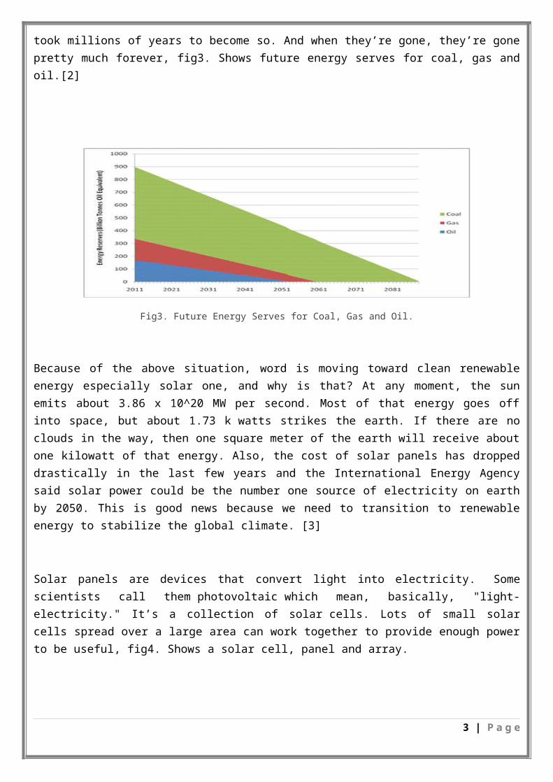
Table 1 Arduino Uno R3 summery.
2. Data Sheet for Servo Motor:
Table 2 servo motor summery
3. Data Sheet for Solar Cell:
PolyCrystalline Cells Solar Panel
6 | P a g e

6V 250mA 135*85mm Small Watt Wholesale Solar Cell
Product Type: Epoxy Solar Panel
Model No.: SM-E1638
Product Construction: Epoxy Resin + Cell + PCB
Maximum Output: 6V*250mA=1.5W
Tolerance: ±3%
Electrical Specification (under standard test condition)
Maximum Output Power (Wmp) 1.5W
Max Working Voltage (Vmp) 6V
Max Charging Current (Imp) 250Ma
Open Circuit Voltage (Voc) 7.2V
Short Circuit Current (Isc) 262Ma
Cell efficiency(η): 16.5%
Materials
Solar cell type: Polycrystalline
PCB FR-4
PCB thickness(mm) 1.0mm 1.2mm 1.5mm
PCB color Black
PCB size(mm) 135*85*2mm
Product thickness: 2.6-2.8mm
Barline: Black tape or none
Physical characteristics
Appearance: Transparent and good polish,
without distortion and loss
Lifetime: 1-3 years
Warning:
1.The mini solar panel can not be placed near to strong corrosive substance
2.Avoid scraping by something hard when using
7 | P a g e

3.Cannot bend during delivery and installation
Using and Storing Condition
Storing temperature 20°C ~ 60°C
Working temperature -20°C ~ 60°C
Table 3 Solar cell SM-E1638 summery
2.3 Earlier Course Work:In this project we had some courses that had been talked about solar cell and motors, as well as using the Arduino including electrical machinery and alternative energy systems and micro-processors.
Also we have visited the energy center in the old campus at An Najah national university and we have gained a lot of knowledge that help us to accomplish our project.
Chapter Three: Literature Review
8 | P a g e

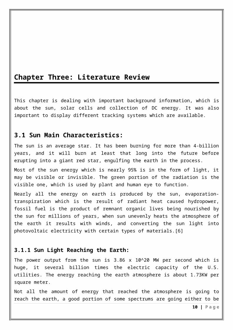
This chapter is dealing with important background information, which is about the sun, solar cells and collection of DC energy. It was also important to display different tracking systems which are available.
3.1 Sun Main Characteristics:The sun is an average star. It has been burning for more than 4-billion years, and it will burn at least that long into the future before erupting into a giant red star, engulfing the earth in the process.
Most of the sun energy which is nearly 95% is in the form of light, it may be visible or invisible. The green portion of the radiation is the visible one, which is used by plant and human eye to function.
Nearly all the energy on earth is produced by the sun, evaporation-transpiration which is the result of radiant heat caused hydropower, fossil fuel is the product of remnant organic lives being nourished by the sun for millions of years, when sun unevenly heats the atmosphere of the earth it results with winds, and converting the sun light into photovoltaic electricity with certain types of materials.[6]
3.1.1 Sun Light Reaching the Earth:The power output from the sun is 3.86 x 10^20 MW per second which is huge, it several billion times the electric capacity of the U.S. utilities. The energy reaching the earth atmosphere is about 1.73KW per square meter.
Not all the amount of energy that reached the atmosphere is going to reach the earth, a good portion of some spectrums are going either to be absorbed or filtered or reflected by the atmosphere. Also, some of which is reflected by the clouds or earth surface, absorbed by the winds to heat them and others, see fig6. Leaving the earth surface with a maximum sunlight intensity of 1 kwatt per meter square.[6]
Fig 6. Conditions that Blocks Sun Light from Reaching the Earth’s Surface
3.2 Solar Cell Theory3.2.1 Photovoltaic:
9 | P a g e

3.2.1.1 General Concept:The word Photovoltaic is a combination of the Greek word for Light and the name of the physicist Allesandro Volta. It identifies the direct conversion of sunlight into energy by means of solar cells. The conversion process is based on the photoelectric effect discovered by Alexander Bequerel in 1839. The photoelectric effect describes the release of positive and negative charge carriers in a solid state when light strikes its surface.[7]
3.2.1.2 Photovoltaic Technologies: The first practical use of solar cells was the generation of electricity on the orbiting satellite Vanguard 1 in 1958. These first solar cells were made from single crystal silicon wafers and had efficiency of 6 %. The space application was for some time the only application of solar cells. The energy crisis in the seventies of the 20th century accelerated a search of new energy sources for terrestrial applications. This search resulted in a growing interest for PV solar energy. The major obstacle of using solar cells for terrestrial electricity generation has been a much higher price of the solar electricity when compared to the price of electricity generated from the traditional sources. Therefore, there has been much effort in the field of solar cells to reduce the price of solar electricity to a level that is comparable to the conventional electricity. The single crystal silicon wafer-based solar cells that had been used in space became also the first solar cells to be used for terrestrial generation of electricity. In order to increase the efficiency of single crystal silicon solar cells and to lower their price, the
Crystalline silicon solar cell technology has improved dramatically in the past twenty years and today it is the dominant solar cell technology. Crystalline silicon solar cell technology represents today not only single crystal silicon wafer-based solar cells, but also multicrystalline silicon solar cells. Both technologies that deal with “bulk” crystalline silicon are considered the first generation solar cells for terrestrial applications. As this technology has matured, costs have become increasingly dominated by material costs, namely those of the silicon wafer, the glass cover sheet, and encapsulates.
In order to decrease the material costs of crystalline silicon solar cells, research has been directed to develop low cost thin-film solar cells, which represent a second generation solar cells for terrestrial application. There are several semiconductor materials that are potential candidates for thin-film solar cells, namely copper indium gallium diselenide (CuInGaSe2=CIGS), cadmium telluride (CdTe), hydrogenated amorphous silicon (a-Si:H).[7]
3.2.2 Different Cell Types:One can distinguish three cell types according to the type of crystal: monocrystalline, polycrystalline and amorphous.
To produce a monocrystalline silicon cell, absolutely pure semiconducting material is necessary.
Monocrystalline rods are extracted from melted silicon and then sawed into thin plates. This production process guarantees a relatively high level of efficiency.
The production of polycrystalline cells is more cost-efficient. In this process, liquid silicon is poured into blocks that are subsequently sawed into plates. During solidification of the material, crystal structures of varying sizes are formed, at whose borders defects emerge. As a result of this crystal defect, the solar cell is less efficient.
If a silicon film is deposited on glass or another substrate material, this is a so-called amorphous or thin layer cell. The layer thickness amounts to less than 1µm (thickness of a human hair: 50-100 µm), so the production costs are lower due to the low material costs. However, the efficiency of amorphous cells is
10 | P a g e

much lower than that of the other two cell types. Because of this, they are primarily used in low power equipment (watches, pocket calculators) or as facade elements.[7]
3.2.3 Solar Cell Physics Analysis:Nuclear fusion reactions on the sun's surface supply earth with solar energy. This energy is primarily released in the form of electromagnetic radiation in the ultraviolet, infrared and radio spectral regions (wavelengths from 0.2 to3m).
Presently, the most efficient means of harnessing this power source is the solar cell, which converts solar radiation directly into electricity.
Solar cells are fabricated from various semiconductor materials using numerous device configurations and selecting single-crystal, polycrystalline, and amorphous thin-film structures.
To following theory considers the silicon p-n junction cell, because it acts as a reference device for all solar cells. The solar cell has a single energy band gap Eg. When the cell is exposed to the solar spectrum, a photon with energy less than Eg makes no contribution to the cell output. A photon with energy greater than Eg contributes an energy Eg to the cell output, and the remaining energy is wasted as heat. [7]
3.2.4 Description of Solar Cell Functionality:Solar cells are composed of various semiconducting materials. Semiconductors are materials, which become electrically conductive when supplied with light or heat, but which operate as insulators at low temperatures.
Over 95% of all the solar cells produced worldwide are composed of the semiconductor material Silicon (Si). As the second most abundant element in earth`s crust, silicon has the advantage, of being available in sufficient quantities, and additionally processing the material does not burden the environment. To produce a solar cell, the semiconductor is contaminated or "doped". "Doping" is the intentional introduction of chemical elements, with which one can obtain a surplus of either positive charge carriers (p-conducting semiconductor layer) or negative charge carriers (n-conducting semiconductor layer) from the semiconductor material. If two differently contaminated semiconductor layers are combined, then a so-called p-n-junction results on the boundary of the layers.[7]
3.2.5 Characteristics of a Solar Cell:
3.2.5.1 Current- Voltage Line of a si-Solar Cell:The usable voltage from solar cells depends on the semiconductor material. In silicon it amounts to approximately 0.5 V. Terminal voltage is only weakly dependent on light radiation, while the current intensity increases with higher luminosity. A 100 cm² silicon cell, for example, reaches a maximum current intensity of approximately 2 A when radiated by 1000 W/m².
The output (product of electricity and voltage) of a solar cell is temperature dependent. Higher cell temperatures lead to lower output, and hence to lower efficiency. The level of efficiency indicates how much of the radiated quantity of light is converted into useable electrical energy. [7]
3.2.5.2 Natural Limits of Efficiency:
11 | P a g e

Theoretical maximum levels of efficiency of various solar cells at standard conditions. In addition to optimizing the production processes, work is also being done to increase the level of efficiency, in order to lower the costs of solar cells. However, different loss mechanisms are setting limits on these plans. Basically, the different semiconductor materials or combinations are suited only for specific spectral ranges. Therefore a specific portion of the radiant energy cannot be used, because the light quanta (photons) do not have enough energy to "activate" the charge carriers. On the other hand, a certain amount of surplus photon energy is transformed into heat rather than into electrical energy. In addition to that, there are optical losses, such as the shadowing of the cell surface through contact with the glass surface or reflection of incoming rays on the cell surface. Other loss mechanisms are electrical resistance losses in the semiconductor and the connecting cable. The disrupting influence of material contamination, surface effects and crystal defects, however, are also significant.
Single loss mechanisms (photons with too little energy are not absorbed, surplus photon energy is transformed into heat) cannot be further improved because of inherent physical limits imposed by the materials themselves. This leads to a theoretical maximum level of efficiency, i.e. approximately 28% for crystal silicon.[7]
3.3 Optimum Angle:
The tilt of the panels is important because your panels will produce a maximum of energy when the sun is directly perpendicular to them. During the winter in the northern hemisphere, for example, the sun is low in relation to the horizon. In this case, for the solar panels to get their best performance, a steep angle of 60° is best. During the spring the best angle is 45°, and during the summer when the sun is high in the sky, it’s best to have a low tilt at 20°![8]
What angle that should be chosen to maximize the production all year long
In solar thermal energy: The aim is to produce more heat in the winter and less heat in the summer. Example: In Marseille, for conventional thermal energy, 4m² of panels are necessary for a typical home’s hot water needs (200 L at 45 ° C) and the best inclination of the panels is between 50° and 55°. This inclination does not correspond to maximum sunshine, but because there is a surplus of production in the summer, it is better to optimize the angle for the winter.
Photovoltaic (PV): For photovoltaic panels where the electricity is re-injected into the grid for re-sale, the optimum orientation is south with an angle of a 37°,which maximizes total electricity production.
PV-T: With the DualSun PV-T panels, which produce both electricity and hot water, the optimal angle is the same as for PV panels.
Example: For a DualSun installation in Marseille, we recommend a 4-panel design for a family of 4. The best angle for that is maximum sunshine (37 °).
Solar panels installed vertically produce less energy, but a façade installation can still make sense depending on the specific needs and constraints of the building. For example, the Arpont shelter has DualSun panels installed vertically. This was a design choice, but also a technical decision to avoid an accumulation of snow during the winter.
12 | P a g e
The impact that does the angle have on production as we diverge from the “ideal angle”?
Fig7. Sunlight Distribution According to Orientation and Tilt Angle.
Does it make sense to adapt the tilt of a roof to optimize production?
In the case of PV-T, when a roof has a fixed slope, it is not necessary to change the angle of the roof to get an optimal production. In fact, the production of energy will always be interesting (which is not necessarily true with thermal solar panels for heating).
The orientation of the panels is important to capture a maximum of sunlight and therefore produce a maximum of energy.
On a fixed installation, the best direction to have the best production is South-facing roofs receive the most sunlight, and therefore the most solar energy during the day.
the impact on production if it derives from this ideal orientation?
If you refer to the diagram above, you will see that further you are from the south, the more your production will be affected.
Does it ever make sense to have panels east/west facing rather than south-facing?
In the case of “self-consumption” for the PV production, it can make sense to orient the panels east/west rather than south-facing. East-facing panels will produce more energy in the morning, west-facing more energy in the late-afternoon. With respect to energy autonomy, the goal is not to produce the maximum but what is needed. This is, for example, the case for the off-grid Arpont chalet in the French Alps, where the DualSun panels are oriented east/west to be able to produce more energy in the morning and the evening and less during the day, when the shelter is pretty empty! [8]
3.3.1 Solar Angle Calculator:
This solar angle calculator tells us the optimum angle to get the best out of our system. To get the best out of our photovoltaic panels, we need to angle them towards the sun. The optimum angle varies throughout the
13 | P a g e

year, depending on the seasons and our location and this calculator shows the difference in sun height on a month-by-month basis.
Of course, the sun is continually moving throughout the day and to get the very best from our photovoltaic system we would need to angle our panels to track the sun minute by minute. We can buy an automated solar tracker to do this.
The sun is at its highest at solar noon each day (this occurs exactly half way between sunrise and sunset) and this calculator shows the angle at that time of day. At solar noon, the irradiance from the sun is at its very highest and we can generate the most power. In the northern hemisphere, the sun is due south at solar noon.
Therefore, to get the very best out of our photovoltaic panels, we would typically face them due south at the optimum angle so that the panel is receiving as much sunlight as possible at this time.
The correct angle for our project will depend very much as to when we want to get the best out of our photovoltaic we would angle our photovoltaic panels according to the height of the sun in the sky during these months. If we want to improve our winter performance, we would angle our photovoltaic panels towards the winter months in order to get the best performance at that time of year.
If we have the opportunity to adjust our photovoltaic panels throughout the year, we will benefit from having the optimum performance from our solar system all of the time.
This solar angle calculator allows us to calculate the optimum angle on a month-by-month basis.[8]
3.4 Solar Tracker Theory:
3.4.1 Introduction of Solar Tracking Techniques:People used to use fixed array panels to generate electricity from the sun, but as the day passes the sun position is changing and may not face the panels for several hours, thus decreasing the output. The tracking system will increase the efficiency by following the sun.
There are several types of tracking systems depending on the way of determining the sun's path, however the main once are fixed control algorithm and dynamic tracking. In fixed control algorithm: the position of the sun is calculated at each time period by an algorithm, it works by previous saved data for a given day, month and year. On the other hand dynamic tracking system uses some techniques to search for the sun position all day.
Both of tracking systems have a control system, and position changing DC motors such as stepper motors or servo motors, which will be directed by the control circuit. [9]
3.4.2 Definition of Solar Tracker:A solar tracker is a device used to change the position of a solar panel in a manner that will make the sun ray's perpendicular to the panel, in order to increase the efficiency.
3.4.3 Methods of Drive:- Active Trackers: Active Trackers use motors and gear trains to direct the tracker as commanded
by a controller responding to the solar direction. The Light-sensing trackers typically have two photo sensors, such as photodiodes, configured differentially so that they output a null when
14 | P a g e

receiving the same light flux. Mechanically, tracker should be Omni directional (i.e. flat) and are aimed 90 degrees apart which will cause the steepest part of their cosine transfer functions to balance at the steepest part and thus translates into maximum sensitivity.
- Passive Trackers: Passive s o l a r Trackers use a low boiling point compressed gas fluid that is driven to one side or the other (by solar heat creating gas pressure) to cause the tracker to move in response to an imbalance.
- Chronological Tracker: Chronological solar Tracker counteracts the earth's rotation by turning at an equal rate as the earth, but in the opposite direction. Actually the rates aren't quite equal as the earth goes around the sun. So the position of the sun changes with respect to the earth by 360° every year or 365.24 days. [9]
3.4.4N Existing Prototype: A solar tracker project by bill lane :
In 2008, Bill Lane has built a solar Tracker for his final year project. Bill lane is a graduate student, from department of electrical and computer engineering, Cleveland State University. In his Solar Tracker project, Bill Lane used a single axis design for the tracker, meaning the tracker only control one angle. Using the Cadmium Sulphide (Csd) as the light sensors, he used 2 light sensor as comparator of the light radiation. When one of the sensor has higher intensity of light, the position of the sun is on the side of that light sensor. Then, by using unipolar stepper motor, the solar panel will be rotate or move until both sensor has the same amount of light on it. Bill Lane solar tracker is using PIC16F877 as the microcontroller of the tracker, the microcontroller has a 10 bits multichannel ADC (analog digital converter), 5 input/output ports and 256 x 8 bytes of data EEPROM memory. 15 Figure 2.10 a) One Axis Tracker b) Light sensor The advantage of this tracker is it used a single axis design. Therefore, the solar tracker must be mounted in fix position where it can be tracker the path of the sun. Refer to Figure 2.11, the one axis tracker only can track path 1 but not Path 2, where to enable the path 2 the tracker must be able to control the azimuth and latitude angle.
Isaac Aunkst received his Bachelor's degree in Electrical Engineering Technology from Penn State Erie, The Behrend College in 2006. Upon graduation he worked for GE Transportation Systems on locomotive electrical and instrumentation systems. He has recently been hired to work on power electronic system design for General Dynamics Electric Boat Division. In 2005 Isaac Aunkst has built a Solar Panel Tracking to increase the efficiency of a photovoltaic (PV) system. 8051 microcontroller was used to control the movement of the solar panel. The system was designed to be autonomous, such that energy generated by the solar panel would be used to charge two lead acid batteries. Isaac Aunkst Solar panel tracking is a single axis design, and by using Light sensor (ldr) to detected the position of the sun. Figure 2.12 Solar Panel Tracking The advantage of Solar panel tracking by Isaac Aunkst is the same with Solar Tracker by Bill Lane where it used a single axis design. To improve the efficiency of the tracker, dial axis can be implementing to control bolt azimuth and latitude of the sun position
15 | P a g e
Chapter Four: Methodology
During our project we have been through the following steps as shown in figure. We have started by reviewing the sun tracking background in order to establish the Microcontroller Based Solar Tracking to perform the specified task. Then we have chosen a mechanical standard design base on some specifications such as minimum price simplicity and higher efficiency. After that, we moved to study Arduino programming to develop the electrical control circuit. Finally we will end with hardware in the next semester.
4.1 Design:When designing our tracking system, we have separated tasks. But talking about the project generally, it involves reading voltages from sensors, then comparing these voltages digitally to determine the direction that the solar panel must move to, aligning itself with the sun. To perform this movement a motor circuit is needed to receive output from the controller and step the motors as a respond. The following sections of this chapter outline the methods and designs used to implement this system.
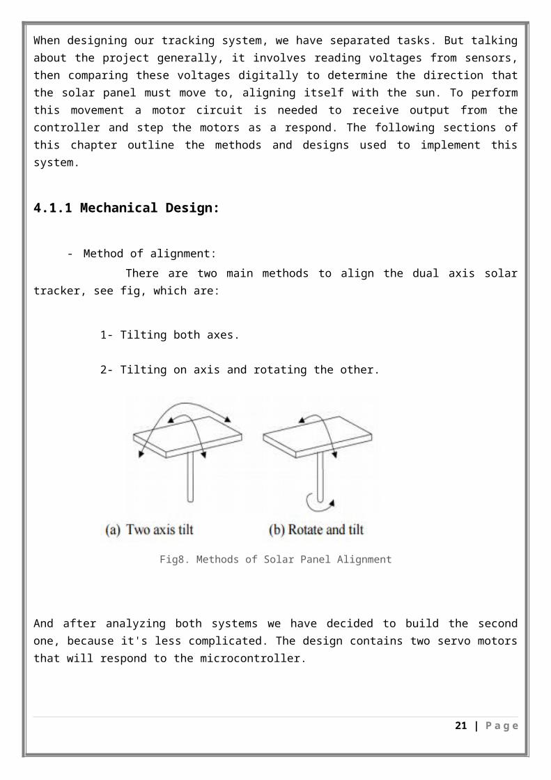
4.1.1 Mechanical Design:
- Method of alignment: There are two main methods to align the dual axis solar tracker, see fig, which are:
1- Tilting both axes.
2- Tilting on axis and rotating the other.
Fig8. Methods of Solar Panel Alignment
16 | P a g e

And after analyzing both systems we have decided to build the second one, because it's less complicated. The design contains two servo motors that will respond to the microcontroller.
Fig9. Suggested Design (Two Motors)
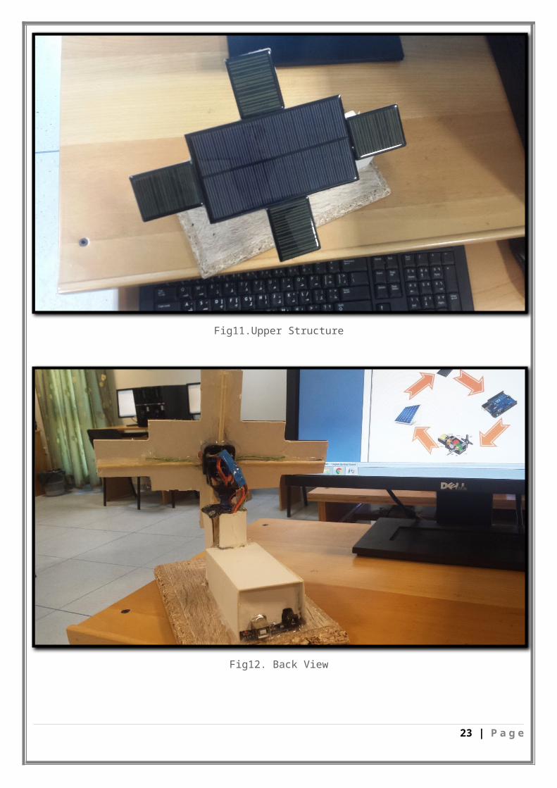
4.1.2 Model Design:For the model we have chosen MOHAMAD FAZMAN BIN MOHAMAD YUNUS design.
It consists of the solar panel, main board, sensor and motor. Figures below 10,11,12 shows our final design.
Fig 10. Base Structure
17 | P a g e

Fig11.Upper Structure
Fig12. Back View
18 | P a g e

4.1.3 Electrical and Electronic Design:
Block Diagram:This block diagram below shows the overview of the working principle of the circuit.
4.2 System Main Components: Polycrystalline Mini PV module. Micro controller (Arduino Uno) Tracking software DC motor (servo)
4.2.1 Servo Motors:
19 | P a g e

A Servo is a small device that has an output shaft. This shaft can be positioned to specific angular positions by sending the servo a coded signal. As long as the coded signal exists on the input line, the servo will maintain the angular position of the shaft. As the coded signal changes, the angular position of the shaft changes. Servos are extremely useful in robotics. The motors are small, have built in control circuitry, and are extremely powerful for their size
Servo motors (see Figure 14) incorporate several components into one device package; a small DC motor; a gear reduction drive for torque increase and an 22 electronic shaft position sensing and control circuit. The output shaft of a servo motor does not rotate freely, but rather is commanded to move to a particular angular position. The electronic sensing and control circuitry which is the servo feedback control loop will drive the
motor to move the shaft to the commanded position. If the position is outside the range of movement of the shaft, or if the resisting torque on the shaft is too large, the motor will continue trying to attain the commanded position.
The servo motor control is inherently consists of the three wires: power, ground, and control. The power and ground wires are simply connected to a 5V supply. in this project, two servos are going to be used. The control signal consists of a series of pulses that indicate the desired position of the shaft. Each pulse represents one position command. The length of a pulse in time corresponds to the angular position. Typical pulse times range from 0.7 to 2.0 milliseconds for the full range of travel of a servo shaft. Most servo shafts 24 have a 180 degree range of rotation. The control pulse must repeat every 20 milliseconds. For this project, four servo motors activating at 5V will be used for tracking the angle of the light radiation (altitude and elevation)..[10]
Fig13. Servo Motor
20 | P a g e

4.2.2 Light Sensor Theory:Light sensors are among the most common sensor type. The sensor circuit design consists of four small polycrystalline silicon solar cells of the same type we used for the major panel. so it seemed like a no-brainer to use them as sun sensors in the tracker. Figure 15 shows Polycrystalline Mini PV Module. In this project, it was desired for the output voltage to increase as the light intensity increases, so the photocell was placed in the top position. The four small solar cells are placed at 90 degrees with respect to each other. The idea was that one cell or the other would get more sun, and the tracker would move until they were getting equal sun.
Fig 14. Polycrystalline Mini PV Module
In this project, it was desired for the output voltage to increase as the light intensity increases, so the photocell was placed in the top position.
Sensor circuit designAfter testing some circuit designs, we have decided simple four- sided with a shadow blocking, see fig16. They are set in a manner such that they have the same voltage when they are pointing to the sun; this is possible because the sensors are set at 90o to the base of the sensor. When the one sensor is not pointing to the sun, the voltage across the other sensor that is exposing more to the sun is going to be higher from the others. Thus a comparator will decide the way of movement, which is toward the higher voltage sensor. Two opposite sensors are used for tilt movement and the others are used for rotational movement.
21 | P a g e

Fig15 .Four-Sided mini polycrystalline solar modules
4.2.3 Tracking Controller:
Arduino Uno:
The Arduino Uno is an open source microcontroller board. It is a small electronic circuit controls the programming of Atmega328 microcontroller, this circuit provides pins to connect electronic components directly to the microcontroller using 14 digital input/output pins (of which 6 can be used as PWM outputs), and also it consists of Crystal Oscillator 16 MHz and USB to connect with the computer. It contains everything needed to support the microcontroller; simply connect it to a computer with a USB or use a battery to get started.[11]
22 | P a g e

Fig16. Arduino Uno
4.2.4 Tracking Program:
The program for the tracking controller has been written in C++ language code for the arduino Uno microprocessor. From the A/D the processor directly accesses the voltages and performs the necessary comparisons. After the comparisons are complete the processor uses a step algorithm to move the servo motors in the direction determined by the comparisons. See appendix A.
4.3 Light Sensor to Microcontroller Circuit:
Light Sensor to Microcontroller Interface Circuit This project implements the usage of 4 mini solar panels. The main reason for these sensors is to program the robot to tracking the sun radiation or a light source. Four of the mini p-v’s namely the south sensor, east sensor and north sensor, and west sensor are used to sense the light source. The 4th pair called the identifier sensor is used to detect the presence of extra stripe on the right hand side. The p-v sensor is connected to the ADC input pin on the microcontroller, see fig 18.
Fig 17. Light Sensor to Microcontroller Interface Circuit.
23 | P a g e
4.4 Complete Circuit:
Fig18. Fritzing Simulation
24 | P a g e

4.5 Flowchart :
Flowchart of tracking algorithm for tilting control is shown bellow; rotation control is done by the same algorithm
25 | P a g e
Chapter five: Results and analysis
The following result was done in EIA, U.S energy information administration. It shows an output power comparison between tracking dual axis, no tracking tilted south, no tracking tilted east, no tracking tilted west, and no tracking flat, during one day in kilowatt see fig19. And during seasons in watt-hour see fig 20.
Fig19. EIA Average Energy Production in a Day[12]
26 | P a g e

Fig21.EIA Average Energy Production in the Four Seasons in Watthour[12]
Because PV panels are able to capture more solar energy when they are pointed directly at the sun, installers may configure systems to optimize output by adjusting the orientation and tilt of a system, or by using mechanisms that track the sun as it traverses the sky.
27 | P a g e

Chapter Six: Conclusions and Recommendations
From the design of experimental setup with microcontroller base solar tracking system using servo motor, if we compare tracking by the use of LDR with fixed solar panel system we expect to find that the efficiency of microcontroller based solar tracking system is improved by 30-45% and we expect that all parts of experimental setup are giving good results.
This tracking system tracks the sun either in continuous manner or every 10 minutes or 15 minutes … etc, and this system is expected to be more efficient and cost effective in long run. The solar tracker can be still enhanced by adding special features in terms of protection from rain and wind in the future work.
28 | P a g e

References:[1] Bloomberg New Energy Finance, UNEP SEFI, Frankfurt School, Global Trends in Renewable Energy Investment 2011
[2] All fossil fuel reserve and consumption data from CIA World Factbook.
[3] "Solar Energy Perspectives: Executive Summary". International Energy Agency. 2011. Archived from the original (PDF) on 2011-12-03.
[4] "Photovoltaic Cell Conversion Efficiency Basics". U.S. Department of Energy. Retrieved 6 Sep 2014.
[5] Percentages derived using the NREL Solar Advisor Model tool by using identical input data, but varying the type of system among fixed frame, single-axis tracking and dual-axis tracking. http://arizonaenergy.org/News_10/News_Nov10/Dual-AxisTrackingGeneratesMorePower.html
[6] Solar Energy Industries Association
[7] National Technical Information Service U.S. Department of Commerce 5285 Port Royal Road Springfield, VA 22161 Stock Number: SERIISP-290-1448
[8] HOME SOLAR PANELS -(10/11/2015) - access by this site http://www.mysolarpannels.com/optimum-angle-for-solar-panels/#ixzz3soIjqrh0
[9] Ignacio Luque-Heredia et al., "The Sun Tracker in Concentrator Photovoltaics" in Cristobal, A.B.,Martí, A.,and Luque, A. Next Generation Photovoltaics, Springer Verlag, 2012 [ISBN 978-3642233692]
[10] "Legend Elite laser series". Epilog Laser. Servo motors are incorporated in both the X and Y axes of every Legend Elite Series laser. These motors are known for their fast acceleration and deceleration speeds.
[11] "Arduino FAQ – With David Cuartielles". Malmö University. , 3/11/2015. Retrieved 2014-03-24.
[12]U.S. EIA (3/11/2015) access by this site- https://www.eia.gov/todayinenergy/detail.cfm?id=18871
29 | P a g e

Appendix A:
#include <Servo.h>
Servo x;Servo y;
int postx = 0;int postey = 0;
int time1 =100;int Cell_Sensor1 = 0;int Cell_Sensor2 = 0;int Cell_Sensor3 = 0;int Cell_Sensor4 = 0;int Cell_Sensor5 = 0;
int timer = 200;void setup() { // initialize serial communication at 9600 bits per second: Serial.begin(9600); y.attach(10); x.attach(9);}
// the loop routine runs over and over again forever:void loop() { // read the input on analog pin 0:
Cell_Read(); /* // print out the value you read: Serial.print("Cell_Sensor1 : "); Serial.println(Cell_Sensor1); delay(timer); Serial.println(""); delay(timer); Serial.print("Cell_Sensor2 : "); Serial.println(Cell_Sensor2); delay(timer); Serial.println(""); delay(timer);
30 | P a g e

Serial.print("Cell_Sensor3 : "); Serial.println(Cell_Sensor3); delay(timer); Serial.println(""); delay(timer); Serial.print("Cell_Sensor4 : "); Serial.println(Cell_Sensor4); delay(timer); Serial.println(""); delay(timer); */ Serial.print("Cell_Val : "); Serial.println(Cell_Sensor5); Serial.println(""); delay(timer);
angleX(); angleY();}
void angleX(){ Cell_Read() ; if (Cell_Sensor1 < Cell_Sensor2) { Cell_Read() ; postx++; x.write(postx); delay(15); if (postx == 160 || postx > 160) { postx = 160; } Cell_Read() ; delay(time1); }
else if (Cell_Sensor1 > Cell_Sensor2) { Cell_Read() ; postx--; x.write(postx); delay(15); if (postx == 2 || postx < 2) { postx = 0; } Cell_Read() ; delay(time1); }
31 | P a g e

}
void angleY() { if (Cell_Sensor3 > Cell_Sensor4) { Cell_Read() ; postey++; y.write(postey); delay(15); if (postey == 80 || postey > 80) { postey = 80; } Cell_Read() ; delay(time1); } else if (Cell_Sensor3 < Cell_Sensor4) { postey--; y.write(postey); delay(15); if (postey == 2 || postey < 2) { postey = 1; } Cell_Read() ; delay(time1); }
}
void Cell_Read() { Cell_Sensor1 = analogRead(A0); //Cell_Sensor1 = map(Cell_Sensor1, 0, 1023, 0, 5); Cell_Sensor2 = analogRead(A1); // Cell_Sensor2 = map(Cell_Sensor2, 0, 1023, 0, 5); Cell_Sensor3 = analogRead(A2); // Cell_Sensor3 = map(Cell_Sensor3, 0, 1023, 0, 5); Cell_Sensor4 = analogRead(A3); // Cell_Sensor4 = map(Cell_Sensor4, 0, 1023, 0, 5); Cell_Sensor5 = analogRead(A5); Cell_Sensor5 = map(Cell_Sensor5, 0, 1023, 0, 5);
}
32 | P a g e