Embed Size (px)
Citation preview

Trends in Electronic Fare Media Technology APTA Technical Report TR-UTFS-FMWG-001-04 Version 1.5 February 14, 2004 Prepared by the APTA Fare Media Research Working Group of the Universal Transit Fare System (UTFS) Task Force Copyrights 2003-2004 by American Public Transportation Association 1666 K St. N.W., Washington, DC 20006 No part of the publication may be reproduced in any form, in an electronic retrieval system or otherwise, without the prior written permission of the American Public Transportation Association.
Copyright 2004 American Public Transportation Association All rights reserved.

Table of Contents
About the Reader ................................................................................................................ 1 1.0 Industry Contributions .................................................................................................. 2 2.0 Introduction ................................................................................................................... 3
2.1 Purpose and Scope .................................................................................................... 4 3.0 Acronyms ...................................................................................................................... 5 4.0 Electronic Fare Media in Review ................................................................................. 6
Table-4-01 Fare Media Standards and Types ................................................................. 7 4.1.0 Contact Smart Card Types ................................................................................... 10 4.2.0 Contactless Types ................................................................................................ 11 4.3.0 Typical Smart Card Application Concerns .......................................................... 12
Smart Card Questionnaire ......................................................................................... 12 4.4.0 Security Encryption Schemes .............................................................................. 15 4.5.0 Key Management ................................................................................................. 17 4.6.0 The ISO/IEC 14443 series Standard .................................................................... 18 4.6.1 ISO/IEC 14443 Technical Overview ................................................................... 19
Proximity Cards ........................................................................................................ 19 ISO/IEC 14443-1 Physical Characteristics ............................................................... 19 ISO/IEC 14443-2 Power and Interface ..................................................................... 19 Table 4-02 ISO RF Types ......................................................................................... 20 ISO/IEC 14443-4 Transmission protocols ................................................................ 20 ISO/IEC 14443 Proximity as a Standard .................................................................. 21
4.6.2 Other Technical and Marketing Considerations .................................................. 21 Proximity Card Market Overview ............................................................................ 21 Table 4-03 Smart Card Market 2002 ........................................................................ 22
4.7.0 Magnetic Strip Card Overview ............................................................................ 22 4.8.0 Contactless Smart Card Readers .......................................................................... 23
PCD or CID Selection ............................................................................................... 24 5.0 (Integrated Circuit Cards) Smart Cards ...................................................................... 25
5.1.1 Contactless Smart Cards ...................................................................................... 26 5.1.1 Contactless Smart Cards ...................................................................................... 27
Table 5-01 Proximity Smart Card Vendor Sampling ............................................... 28 5.1.2 ISO 14443 Type A Contactless Smart Card (PICC) Examples ........................... 28 5.1.3 ISO 14443 Type B Contactless Smart Card Examples ........................................ 31 5.2.0 Dual Interface Smart Cards .................................................................................. 33 5.3.0 Other Integrated Circuit Smart Card Types ......................................................... 34
FeliCa Contactless IC Card System .......................................................................... 35 5.4.0 GO CARD® .......................................................................................................... 37
6.0 Non-IC Smart Card Technologies .............................................................................. 38 6.1.0 Capacitive Cards .................................................................................................. 38 6.1.1 Primary Capacitive Technology .......................................................................... 39
Diagram 6-01 Capacitive Card ................................................................................. 39 6.1.2 Secondary Capacitive Technology ...................................................................... 40 6.1.3 Capacitive manufacturing and encoding .............................................................. 40

Diagram 6-02 Capacitive Card Encoding Machine .................................................. 40 6.3 Optical Cards .......................................................................................................... 41
7.0 Magnetic Cards ........................................................................................................... 43 7.1.0 Theory .................................................................................................................. 43
Magnetic Tape .......................................................................................................... 43 7.1.1 Magnetic Tape Foil .............................................................................................. 44
Manufacturing ........................................................................................................... 44 7.1.2 Magnetic Ticket Size ........................................................................................... 44
Card dimensions and tolerances (Card Size ID-1) .................................................... 44 Figure 7-02 — Card dimensions ............................................................................... 46
7.1.3 Magnetic Ticket Size (Example) ......................................................................... 46 7.1.4 Magnetic Ticket Materials ................................................................................... 47 7.1.5 Testing Magnetic Cards ....................................................................................... 47
Testing Mag Stripe Tickets and Readers .................................................................. 47 Magnetic Stripe Media and Ticket Testing............................................................... 48 Calibration and Test Tickets and Cards for Systems Testing ................................... 50
7.2.0 Magneprint ........................................................................................................... 51 7.3.0 Extended Life Magnetic Heads ............................................................................ 51
Dirt and Wear Resistant Magnetic Head and Coatings ............................................ 51 8.0 Processing, Printing, and Encoding of Magnetic and Smart Cards ............................ 53 9.0 Data Formats ............................................................................................................... 54
Table 9-01 Smart Card Issuer Record Format Table (Example) .............................. 56 9.1 Calypso ................................................................................................................... 57 9.2 ITSO ........................................................................................................................ 59
Figure 9-02 The ISTO Approach .............................................................................. 59 9.3.0 ITSO and CALYPSO Collaboration .................................................................... 60 9.4.0 New York & New Jersey Regional Smart Card System ...................................... 60
Table 9-03 The Port Authority of NY & NJ’s Regional Interoperability Standard 62 9.5 MTC TransLink® Regional Smart Card Specification ........................................... 62
10.0 Actual Case Studies of Fare Media Implementations ............................................... 63 Chicago Case Study ...................................................................................................... 63
Policy Issues ............................................................................................................. 64 Table 10-01 Sample Benefit Matrix (specific to Chicago program) ........................ 65
Los Angeles, the Second Case Study ............................................................................ 66 LACMTA Decision for Smart Card Technology ..................................................... 66 Chart 10-01 Lifetime Capital and Operating Cost .................................................... 68 Chart 10-02 Transaction Time Comparisons ............................................................ 69
11.0 Trends and Futures .................................................................................................... 69 11.1 Third Generation Smart Card Products ................................................................ 70
TI Apollo ................................................................................................................... 71 Table 11-01 “Apollo” ISO/IEC 14443 Type B Secure Chip .................................... 72 MIFARE® DESFire ................................................................................................... 72
11.2 Limited Use Smart Cards ...................................................................................... 73 Table 11-02 Limited Use Process and Cost Structure Example ............................... 76 C. Ticket .................................................................................................................... 77

Limited Use Standards Activity and Status .............................................................. 77 11.3 Magnetic Developments ....................................................................................... 78
11.3.1 Combo Digihead (Magnetics) and Smart Card Reader ................................. 78 11.3.2 High Density Magnetics ................................................................................ 78 11.3.2.1 High Density Recording ............................................................................. 78
11.4 Nanotechnology and Polymer Electronics ............................................................ 81 11.5 Near Field Communications ................................................................................. 81 11.6 Printing Technology ............................................................................................. 82 11.7 Exploring Other Technology Directions ............................................................... 83
Back End Clearinghouse Payments .......................................................................... 83 AVM Card Sales – Different Card Types ................................................................. 83 Wireless networks to retrieve transaction data ......................................................... 83 ATM Sales ................................................................................................................ 83 Point of Sale Devices ................................................................................................ 84 Autoload Feature ....................................................................................................... 84 Credit Card Acceptance ............................................................................................ 84 11.7.1 Electronic Payments ...................................................................................... 84
12.0 Executive Summary .................................................................................................. 85 Annex-A Glossary ............................................................................................................ 87 Annex-B References ......................................................................................................... 94
Other References: ..................................................................................................... 94 Annex-C Trademarks ........................................................................................................ 95


TR-UTFS-FMWG-001-04 Version 1.5
February 14, 2004
About the Reader There are surprisingly very few documents written which specifically address the needs of the public transportation sector, considering the number of people this industry touches each and every day. As transportation demand increases, so does our transportation providers’ requirement to optimize levels of service. Experience is one of the best teachers and therefore becomes critical to the success of our efforts here. We must focus not only on the future technology but also on fare payment systems implemented thus far: to look at the advantages and disadvantages of each. Many documents available today are somewhat dated or primarily focus on rolling stock or possible future modes of public transport. Documents published by the Federal Transit Administration Research, Stanford Research Institute, and various reports to the US Congress such as “Tomorrow’s Transportation” only touch the surface of fare collection. Documents that focus upon fare collection and more specifically electronic fare media are usually provided in the form of conference proceedings mainly from the American Public Transportation Association (APTA) or independent consulting documents or white papers. There are also several non-US publications, but again, they tend to take on the same surface level coverage of fare media. APTA and its members have accepted the challenge to place a greater focus upon up-to-date public transportation fare media research as we move into the 21st century. This document was written for those who wish to learn what fare media solutions and product offerings are available. The research documented here more specifically focuses on electronic fare media technology. The document is intended to direct the reader toward electronic fare media technology encompassed by standards for media selection as well as implementation guidelines. In addition, the document provides an historic background in fare media while focusing on technology that allows for solutions applicable today and in the near future. The intended reader is one who has a need and appreciation for improving public transportation fare collection systems. The reader should have a basic understanding of the process flow of fare collection as well as a general awareness of fare media. The reader who is in search of direction and unbiased knowledge of various electronic fare media choices and core technologies will be best served by this document. You can expect to gain knowledge about the various technologies that have been adapted to meet international standards, defacto regional standards as well as technologies that are attempting to gain acceptance as standards. The reader will also be given a view into future core technologies that will enlighten as to the possibilities of electronic fare media as the public transportation sector moves through the early stages of the 21st century. The information provided is an attempt to expose the reader to all known electronic fare
Copyright 2004 American Public Transportation Association Page 1 All rights reserved.

TR-UTFS-FMWG-001-04 Version 1.5
February 14, 2004
media products and technology and to provide an open and objective process for understanding and evaluating electronic fare media. 1.0 Industry Contributions ASK Corp. Sophia Antipolis, France ATMEL Semiconductor Santa Clara, CA, USA Bay Area Rapid Transit Oakland, CA, USA Booz-Allen Hamilton, Inc. San Francisco, CA, USA Brush Industries, Inc. Sunbury, PA, USA C-CARD, Inc. Victoria, BC, Canada Chicago Transit Authority Chicago, IL, USA Cubic Transportation Systems San Diego, CA, USA FC Consulting, Inc. San Diego, CA, USA Fujitsu Electronics Devices Shinjuku-ku, Japan Kovio, Inc. Sunnyvale, CA, USA Los Angles Metropolitan Transit Los Angles, CA, USA New York Transit Authority New York City, NY, USA On Track Innovations Rosh Pina, Israel PBS&J Consulting Orlando, FL, USA Philips Semiconductors Foxboro, MA, USA Sony Corporation Tokyo, Japan ST Microelectronics Rousset, France Texas Instruments Plano, TX, USA Three Point Consulting, Inc. Escondido, CA, USA Washington, DC, Metropolitan Area Transit Authority Washington, DC, USA
Copyright 2004 American Public Transportation Association Page 2 All rights reserved.

TR-UTFS-FMWG-001-04 Version 1.5
February 14, 2004
2.0 Introduction Electronic Media is an extensive subject that continues to evolve with new and exciting technologies and solutions being developed at an ever-increasing pace. The transportation industry is driving many aspects of this innovation and therefore multiple options are now being made available. This document’s purpose is to bring awareness and knowledge to the reader who is tasked with the selection or support of electronic fare media. The transit industry has become a significant user of electronic media and is increasing its use of the various technologies daily. Other industries such as banking, security and retail are also participating with transit to better utilize this form of electronic media. Electronic media applications are now common in all of these industries. The coexistence of transit fare applications with other industry applications on electronics fare media products has made progress during the last two-years. To comprehensively represent all of the electronic media products that can fulfill the requirements of transit fare media this document will address, to the degree possible, the following key technologies: Integrated Circuit Cards (Smart Cards), Magnetic Cards, Capacitive Cards, and Optical Cards. Most of the variations of electronic fare media cards presently used in transit can be categorized into one of these types. Further, Electronic Fare Media is defined as any portable media that contains the ability to store and retrieve data in a non-volatile manner by a method of electronically reading, writing, or both. This document is divided into eight primary subjects that include: Electronic Fare Media in Review, Integrated Circuit Cards (IC), Non-IC Cards, Magnetic Cards, Encoding Systems, Data Formats and System Solutions, Actual Case Studies, Trends and Futures followed by an Executive Summary and Conclusions. The only two sections that need introductions are Fare Media in Review and Future Technologies. First, Electronic Fare Media in Review: this section contains detailed information about all of the presently used and available fare media types with their capabilities and limitations. It also contains a list of all fare media technologies that are classed as standards, as well as others that do not presently carry a recognized standards certification, such as ISO, IEC, ANSI or IEEE. Second, Trends and Futures: this section provides technologies that are either making their way into the industry as of the publishing date of this document or are highly probable within the next two years. In addition, this section provides a degree of speculation on the subject of transit fare media technology directions and usage to provide the reader with a degree of industry direction.
Copyright 2004 American Public Transportation Association Page 3 All rights reserved.

TR-UTFS-FMWG-001-04 Version 1.5
February 14, 2004
2.1 Purpose and Scope Public transportation fare collection systems have advanced significantly in the last decade with the advent of various electronic fare media technologies. These technologies have improved fare collection systems in our industry. The technology, however, has advanced to the point where a benchmark is necessary to uniformly educate decision makers. It is intended that this document provide a condensed but reasonably comprehensive source of factual information, with background on the various electronic fare media available to, or proposed for, the transit industry. The document does not endorse a specific solution. It simply provides objective information that allows the decision maker to effectively decide and direct which fare medium is best to meet the needs of their fare payment system. The document provides a transportation-related history of electronic fare media, sample descriptions of the adopted technologies, and a review of applicable standards. A discussion of technologies either planned or not yet adopted as standard is provided as well. This document does not address non-electronic solutions, nor solutions that are not used on an international basis. It is beyond the scope of this document to discuss every available technology and commercial product currently in use. It is hoped, however, that enough information is provided about widely adopted and proposed technologies so that the reader can, at a minimum, move one step closer to justifying and supporting fare media decisions.
Copyright 2004 American Public Transportation Association Page 4 All rights reserved.

TR-UTFS-FMWG-001-04 Version 1.5
February 14, 2004
3.0 Acronyms AES: Advanced Encryption Standard AFC: Automatic Fare Collection ANSI: American National Standards Institute APTA: American Public Transportation Association ASK: Amplitude Shift Keying ATM: Automatic Transaction Machine ATRA: Advanced Transit Association AVM: Automatic Vending Machines BART: Bay Area Rapid Transit bps: bites per second Bps: Bytes per second BPSK: Binary Phase Shift Keying CDMA: Code Division Multiple Access CDPD: Cellular Digital Packet Data CEN: Committee for European Standardization CID: Card Interface Device COS: Card Operating System CSC: Contactless Smart Cards CTA: Chicago Transit Authority DES: Data Encryption Standard DSP: Digital Signal Processing ECMA: European Computer Manufacturers Association EEPROM: Electrically Erasable Programmable Read-Only Memory EE RAM: Electrical Erasable Random Access Memory etu: elementary time unit fc: Frequency of carrier fs: Frequency of Sub carrier FeRAM: Ferro-Electric Random Access Memory FIPS: Federal Information Processing Standards FM: Frequency Modulation FTA: Federal Transit Administration GPRS: General Packet Radio Service GSM: Global System for Mobile Hc: Coercivity HiCo: High Coercivity IC: Integrated Circuit IEC: International Electrotechnical Commission IEEE: Institute of Electrical and Electronic Engineers IOPTA: Interoperable Public Transportation Applications ISO: International Standards Organization or International Organization for Standards K (k): Kilo (as in Kilo bytes)
Copyright 2004 American Public Transportation Association Page 5 All rights reserved.

TR-UTFS-FMWG-001-04 Version 1.5
February 14, 2004
LoCo: Low Coercivity LU: Limited Use Smart Cards MAG: Magnetic MB: Million Bytes or Mega Bytes MFM: Modified Frequency Modulation Mhz: Million Hertz or Mega Hertz MRAM: Magnetic Random Access Memory msec: millisecond NFC: Near Field Communication NIST: National Institute of Standards and Technology NRZ-L: Non-Return to Zero Level nsec: Nanosecond NYCT: New York Transit Authority OOK: On/Off Keying OTP: One Time Programmable NY/NJPA: New York/New Jersey Port Authority PCD: Proximity Coupling Device PDA: Personal Data Assistant PICC: Proximity Integrated Circuit Card PKI: Public Key Infrastructure RAM: Random Access Memory RATP: Regional Paris Transit System RF: Radio Frequency RFID: Radio Frequency Identifiable Device RISC: Reduced Instruction Set Computer ROM: Read Only Memory SAM: Security Access Module SHA-1: Secure Hash Algorithm, type -1 Si: Silicon SIM: Security Interface Module SJT: Single Journey Ticket SNCF: National Railway of France SVT: Stored Value Ticket TAM: Total Available Market TTL: Transistor-Transistor Logic UTFS: Universal Transit Fare Card Standards W-CDMA: Wideband Code Division Multiple Access WMATA: Washington, DC, Metropolitan Area Transit Authority 4.0 Electronic Fare Media in Review This section contains four sub-sections that will cover, in detail, the different types of electronic fare media as described in the Introduction. In Table 4-01 each of the fare
Copyright 2004 American Public Transportation Association Page 6 All rights reserved.

TR-UTFS-FMWG-001-04 Version 1.5
February 14, 2004
media is listed with supporting standards, assigned numbers, and any specific or supporting notes. This table provides an excellent summary reference to the various electronic fare media products and their association with standards. The rest of this section brings a greater level of knowledge about each of the fare media technologies. At times, specific vendor products are mentioned to bring further understanding or awareness of available solutions and what they encompass. Table-4-01 Fare Media Standards and Types
Type of Fare Media
Applicable or proposed ISO
standards
Specifics Notes
Magnetic Cards 4909 Bank Cards (Track number
three)
Magnetic Cards 7811-1 Embossing
Magnetic Cards 7811-2 Recording techniques
Low Coercivity
Magnetic Cards 7811-3,4,5 Magnetic Track location
Magnetic Cards 7811-6 Recording techniques
High Coercivity
Magnetic Cards 10373-2 Test-methods
Magnetic Cards Proposed High-density Greater than 1000 bits per inch
Magnetic Cards 15457 Thin Flexible Cards (Physical magnetic,
tests)
Optical Memory Cards
11693 General Characteristics
Optical Memory Cards
11694 Parts 1,2,3,4 Recording (Physical, Format)
Master document
Optical Memory Cards
10373-5 Test-methods
Contactless Smart Cards
14443 Parts 1,2,3,4 Physical, RF- Modulation,
Initialization, and
Master document
Copyright 2004 American Public Transportation Association Page 7 All rights reserved.

TR-UTFS-FMWG-001-04 Version 1.5
February 14, 2004
Protocol
Contactless Smart Cards
14443 addressed by: 10373-6
Test-methods Proposed 2003 addition to ISO 14443 Support
Contactless Smart Cards
10373-6 Test-methods Additional action being taken on these test methods at this time
Contact Smart Card
7816 Parts 1,2,3,4,5,6
Physical, Protocols, Interchange,
Registration and Data Elements
Master document
Contact Smart Card
10373-1 General Characteristics
Reference only
Credit Card 7810 Physical Characteristics of Credit Card Size
Documents
Identification Cards (RFID Tags)
15693 Part 1,2,3 Physical, Initialization, Anti-
Collision and Protocol
Identification Cards
(RFID Tags)
10373-7 Test-methods
Other Electronic Fare Media Offerings
Capacitive Cards Proposed Listed as a consideration
Dual Interface Smart Cards
Contains 7816 and 14443
Monolithic Silicon
Limited Use Smart Cards
14443 proposed new-work order
Low cost having limited functionality that offers an alternative to magnetic ticketing
Copyright 2004 American Public Transportation Association Page 8 All rights reserved.

TR-UTFS-FMWG-001-04 Version 1.5
February 14, 2004
Tri-Plex Magnetic Cards
Based upon 7811 Customized packaging materials
Smart Tokens Based on 14443 This may be incorporated in the new proposed work effort for Limited Use 14443
Copyright 2004 American Public Transportation Association Page 9 All rights reserved.

TR-UTFS-FMWG-001-04 Version 1.5
February 14, 2004
Copyright 2004 American Public Transportation Association Page
4.1.0 Contact Smart Card Types Contact card technology was first embraced by the Banking and Telecom industries. The reason behind this acceptance was contact technology being made available with reasonable transaction security through multiple suppliers at a reasonable cost. In particular, the banking industry was in search of a worldwide payment method that is more secure than magnetic stripe cards, e.g., traditional credit and check/debit cards. The telecom industry desired to remove coins from pay phones as well as to provide a reasonably secure pre-paid phone card option to its customers. There are advantages associated with contact-based smart cards over that of contactless, the first being the high probability that a transaction will be completed, since many of the contact readers are designed to capture and lock the card until the transaction is completed. This prevents the possibility of a transaction “tear.” A “tear” occurs when a smart card (PICC) transaction is abruptly terminated in the midst of writing transaction data to the PICC. Most pay phones, for example, do not capture the card and, therefore, “tearing” of the payment transaction can occur. Secondly, contact cards are not subject to RF interference, since there is no activation of RF-emitting energy. Third, contact card readers, on average, are less costly to manufacture than contactless readers. Lastly, contact cards have been issued and used for over a decade in high volume (in excess of 10 million units), providing practical experience with applicable international standards, effective solutions for transaction security, and numerous, competitive sources for manufacturing. Contact cards require a power source of 3.3V to 5V DC. These cards must be inserted into a smart card reader. These cards most often contain gold or silver-plated contacts from which the card derives its power and signals. Two disadvantages to these physical contacts are: that contacts will eventually wear down or dislodge from the card body, and that contacts require the docking of the card into a reader slot. Below is an example of a contact multifunction smart card from Toshiba Corporation:
10 All rights reserved.

TR-UTFS-FMWG-001-04 Version 1.5
February 14, 2004
Copyright 2004 American Public Transportation Association Page
For transit fare gate or fare box entry and exit purposes, contact cards represent significant increases in transaction or “dwell” time and the physical challenges of inserting these cards into a card reader slot. They are less friendly toward patrons with disabilities: only one orientation is correct, and so on.). Maintenance is one of the largest components of a transit agency’s budget. A well understood contributor to system maintenance cost is keeping any physical point of electrical contact clean to insure system functionality. Contact cards require such a point of electrical connectivity, and expensive card and reader/writer replacement costs are incurred due to harsh environmental conditions, introduction of liquids and other materials into the reader’s card slot, and vandalism. Contact card technology is now often integrated with contactless technology, providing a dual interface card product. This type of card product bridges both technologies, but does so at an additional cost per card. There are some applications that use both technologies; for example, to load value via the contact interface while the contactless mode is used for making purchases. It is worth mentioning that several banks and credit card organizations are now sampling or experimenting with contactless card banking transaction loads/transfers and expenditures. The early but limited success of contactless card products could indicate the eventual end of contact smart cards. 4.2.0 Contactless Types Tags, Radio Frequency Identification (RFID), Proximity Integrated Circuit Card (PICC), and Smart Cards are the most commonly used terms for referencing a device that communicates via radio frequencies (RF). These devices are often equipped with rewriteable stored memory and, at times, a processing unit such as a state machine or microprocessor. It is important to note that the term smart card is used interchangeably to refer to an RF or contactless device as well as to a contact or wired device. This document discusses, for the most part, contactless smart cards, but will address various contact smart card-related issues. (The term smart card will be used generically as a
11 All rights reserved.

TR-UTFS-FMWG-001-04 Version 1.5
February 14, 2004
Copyright 2004 American Public Transportation Association Page
reference to both contact and contactless technology throughout this document. These two smart card technology definitions will be described in greater detail later in this document and within the document glossary.) It is necessary to include both technologies since some of the latest generations of smart cards have been designed to support both interface technologies. This type of smart card product is generally called Dual Interface (monolithic circuits) or Hybrid (differentiated circuits). There is growing interest and acceptance of this type of product where the use environments vary and may require either a contact or a contactless interface to the card, depending on the level of security that must be applied and the amount of transaction time available. These devices are seeing new popularity, especially in the financial, security and transportation industries. These intuitions are focusing on establishing an interoperable means of relating to each other’s applications. Much of this focus is being fueled by the ever-improving contactless technology that acts as an interoperable technology catalyst. This brings into the forefront both opportunity and technical debate as to the adoption of contact, contactless, dual-interface or hybrid cards. At odds are the priority set on the requirements to satisfy each of their specific markets, and the operational requirements of each of the three industries. It is not the intention of this document to side with either of these industries or the technology options but to offer a better understanding of the technology, adoption and implementation requirements of smart cards as fare media for transportation applications. 4.3.0 Typical Smart Card Application Concerns The numerous technical variations of smart card products being offered by a growing list of suppliers provide us with a nearly incomprehensible list of options. There is a set of basic questions, however, that can be used to allow the card issuer to focus on the appropriate solution for his or her needs. These questions include: Smart Card Questionnaire
System Operations Related Issues a.) What are the budget and/or cost goal requirement for each card or the system
population of cards? That is, is the card cost a major concern and, if so, can the cost be recovered from the cardholder or another revenue source?
b.) What volumes of cards are expected for the next three years? Also, when and
in what anticipated quantities will cards need to be replaced either due to expiration or typical use?
c.) What level of card durability and life cycle is required?
12 All rights reserved.

TR-UTFS-FMWG-001-04 Version 1.5
February 14, 2004
Copyright 2004 American Public Transportation Association Page
d.) What type of manufacturer warranty is issued with each card? e.) Will there be a policy or requirement for card registration and unique
serialization?
f.) Will there be a need to support biometric images or advertisement images? What types of applications are required?
g.) Will there be more than one application requiring data file space on the
card?
Performance and Policy Related Issues and Physical Requirements h.) How much time should a complete transit fare transaction take to complete
before system performance degradation becomes an issue?
i.) Is the physical environment for the readers conducive to a contact-based solution?
j.) What is the system’s PICC to PCD distance read and write requirement?
k.) What level of security is required for card transactions? Does that level vary
with different types of transactions? l.) What are the projected requirements for on-card memory? m.) Does the issuer plan on using a particular Record Byte Length?
n.) Is transaction Tear therefore Anti-Tear an important consideration? o.) Will there be a requirement for a magnetic strip?
p.) Will the system require post-issuance printing on the card?
q.) What is the projected size of the memory needed to fulfill the application(s)? r.) Does the issuer plan on using a particular Record Byte Length? External Factors s.) Will a third party (i.e.: a bank, etc.) be involved as a card issuer? If so, what
are that party’s security requirements for card transactions? t.) Will the card be used exclusive for transit fare payment?
13 All rights reserved.

TR-UTFS-FMWG-001-04 Version 1.5
February 14, 2004
Copyright 2004 American Public Transportation Association Page
u.) Is there a need to support multi-applications with a microprocessor-based
smart card and a specific operating system, or will the capabilities of a memory logic card suffice?
v.) Do the system decision makers require Dual Interface or another specific
card type or function? Is there a need for interoperability with systems? Standards Related Issues w.) Is it important to have an ISO/IEC-14443 compliance an important
consideration? If so, are all four parts of that standard going to be applied? Will both types A and B under the standard be utilized?
x.) What type of anti-collision is required? Is anti-tear a system requirement? If
so, can it be resolved through the software application and/or smart card device?
y.) Does the transit agency or issuer need to adhere to a government requirement
to buy from a given country or regional supplier? z.) Has the technology successfully been deployed and is the technology
available from more than one vendor?
Note: It is of little value to provide an example answers matrix since the answer
variations for the different issuer/adopters could lead to several different end results having a very specific product requirement. Instead, the readers are encouraged to build their own specific answer matrix and align this matrix in the following manner:
• First, group transaction time, RF, electrical, and standards requirements
• Second, group all of the questions that pertain to application, memory size, and byte organization requirements
• Third, group security, microprocessor, non-microprocessor, operating system, and interoperability requirements
• Fourth, group policy, printing, and specific card product requirements
• Fifth, group cost, warranty, and delivery requirements The combination of these groups will allow the issuer/adopter to focus in on a few options available that will meet the specific criteria. In most cases there will be less than five smart card product choices that provide a reasonable fit for a given system.
14 All rights reserved.

TR-UTFS-FMWG-001-04 Version 1.5
February 14, 2004
Copyright 2004 American Public Transportation Association Page
4.4.0 Security Encryption Schemes This can be an extensive topic as evidenced by the number of books written to specifically address this subject. The intent of this section’s coverage is to provide the reader with a general understanding of the various security schemes implemented in smart cards. (Recommended reading is the book Secrets & Lies by Bruce Schneier). Security requirements for a system will vary depending on the environment in which cards will be used, the type of transaction being performed, and the opportunity for financial gain that is created if the security scheme is broken. In all cases, it would be prudent to say that some level of security is required in all cases. There are several environmental and operating policy considerations that must be considered in order to determine the level and type of security required. If the issuer or user is concerned with the creation of counterfeit cards, as an example, the security scheme should most likely invoke the use of an encryption key methodology. Encryption keys are unique alphanumeric values that are stored in a highly secure place so that only the intended parties can have access. One key may be used to facilitate initial loading of information to the card memory, while another might be used to authorize the addition of stored value, and yet another could be used to allow value to be deducted. The methodology dictates which keys are stored on the smart card, which are used by the reader/writer device, and which are used by the central system so that these devices can communicate securely and provide a level of protection from unauthorized device duplication. The methodology may also define a regular schedule for key updates (“rolling”) to insure that the key set is dynamic, making card counterfeiting even more difficult to accomplish. Taking this to a higher level, these keys can be diversified. This is the method of taking the master key set or subset through an algorithmic formula combining the keys with other card, cardholder, or variable information. The result is a new key value that has its origins from the original master key but also has origins from the other introduced data or value. This result in a second layer of key protection since, the actual master key is never transmitted or resident in an externally accessible memory form. Even in the rare event the diversified key was deciphered illegally from the card or reader/writer/PCD, usage of the key is limited, since it can be applied only to a counterfeit of one card and should easily be detected once the counterfeit card is used within a monitored system. Data Encryption Standard (DES) Diversified keys have become important primarily due to the ever-increasing availability of computational processing power available to the average citizen. For example, it is now estimated that a single DES key of 48 to 56 bits in length can be deciphered in less than 20 minutes with off-the-shelf computers. Even with an increased key length, key
15 All rights reserved.

TR-UTFS-FMWG-001-04 Version 1.5
February 14, 2004
Copyright 2004 American Public Transportation Association Page
deciphering is simply a matter of time and the application of computational power in what is known as the “brute force method”. In the brute force method, a computer (or multiple computers) is used to attempt transactions with the card by guessing the appropriate key. If the transaction fails, the transaction is repeated with an alternate key until success is achieved. Triple DES (3-DES) A more advanced key encryption scheme known as 3-DES makes computational deciphering much more difficult, since there are several orders or “layers” of key values to decipher. This method is widely used in banking and other payment applications to insure higher levels of security. Use of this methodology in smart cards, however, offers the disadvantages of slower transaction times as well as increased requirements for device circuitry. Continued semiconductor technology advancements with increasingly robust transistor circuits and reduced process geometry are improving smart card performance, even when 3-DES is applied. The newly improved but not yet widely implemented version of this methodology is the AES security algorithm. AES is starting to generate interest among security-concerned implementers. Digital Signatures A Digital Signature is a mathematical security method or operation that generates a unique value (“signature”) that is applied to a package of information or data. The use of digital signatures is advantageous in that it can minimizes transaction speed impacts and because it requires little additional circuitry on the smart card. This security method is often used with “Limited Use” cards. Using this method, authentication of the card is confirmed by a reader (and vice versa, depending on the implementation method selected) through an exchange of the card’s digital signature. The reader performs a comparison of that value to a known correct value stored in the reader’s or back-end system’s memory to verify the validity of the card. This approach has an inherent weakness, however, since the reader captures the card’s digital signature, making it possible to create counterfeit cards. The scheme relies on the notion that only the card and reader know the other’s digital signature value. Public Key Infrastructure (PKI) PKI is a security encryption methodology that utilizes encryption key pairs to authenticate transactions or data packets. One of the keys is a public key and, as its name implies, can be disclosed to any third party. The second key is the private key and is known only to the owner and trusted third parties. Like a digital signature, the public key can be used by a third party to confirm that information it receives originated from the appropriate entity and, in certain instances, to decrypt data that has been provided by that entity in an encrypted form. The private key is used by the key holder to encode data before sending it to another party. Depending on the methodology applied, the recipient
16 All rights reserved.

TR-UTFS-FMWG-001-04 Version 1.5
February 14, 2004
Copyright 2004 American Public Transportation Association Page
might use the public key to decipher the information or may require the private key. PKI provides one of the highest levels of transactional security commonly available today. PKI involves both mathematical numbered operations and an operational process. PKI is being used by organizations such as that of the US Department of Defense for very secure building access and logical computer access. This type of PKI system requires extensive “Stove Pipe” backend operations (referring to a complex central organization that is responsible for security generation, organization, issuance and maintenance), to issue and maintain a secure smart card system. PKI is very transaction time intensive, making it a poor choice for transportation-related fare payments. Mutual Authentication Mutual Authentication is a method used to securely identify and authenticate access to data on the card and reader. A typical implementation method of authentication is through the use of passwords or keys although any of the methods described above can apply. The process is simply the comparison and verification of known values (passwords or keys) by both the card and the reader to ensure that both are authenticated before transactions are initiated. This approach is advantageous in that it minimizes the opportunity for the successful introduction of a counterfeit card or reader into the system and provides an added layer of security each time a card is used. 4.5.0 Key Management A smart card is a portable, physical device in which keys and digital certificates may be stored. Complimentary to the smart card is the CID where keys may and should be stored. There are a host of key management operations and procedures that dictate how keys and certificates will be generated, loaded, removed, stored, and otherwise managed. Key Management specifications often vary with established key management system requirements in reference to different levels of security handling. The adequacy of the key management approach is critical to the security of all systems that rely on the smart card and CID. Weak, ineffective key management approaches could undermine the applications that rely on the smart card for cryptographic security services but from the perspective of operational effectiveness, burdensome key management solutions could render the smart card nearly unusable. Key management approaches must be able to support diverse operational environments and be aligned to the transit application(s) and agency requirements as well as the agencies capabilities. Keys must be able to be added or changed without necessitating a return to some central issuing authority. Thus, the key management requirements applicable to cryptographic smart cards and CIDs must achieve a comfortable balance between the sometimes-competing needs of security, functionality and performance. It is highly recommended that agencies seek knowledgeable support and advice before establishing a regional security scheme.
17 All rights reserved.

TR-UTFS-FMWG-001-04 Version 1.5
February 14, 2004
Copyright 2004 American Public Transportation Association Page
4.6.0 The ISO/IEC 14443 series Standard A little history is necessary here to gain a better appreciation for the dual interface modes within ISO 14443 Type A and Type B. In the development of the contactless standard ISO/IEC 14443, which was assigned as a work project by SC1/WG8 in 1994, the work progressed slowly at first because the task force was faced with determining what the industry really wanted and needed in a contactless card. Up to this point in time contactless cards were actually RF-Tags that would just respond with a serial number when brought into an RF field. The actual action or transaction was done by the reader system that produced the RF field and detected the tag’s serial number. There were many companies and countries that contributed information for a working draft for the ISO/IEC 14443 series of contactless standard. As a result the task force defined four parts to this standard. They are:
Part 1: Physical Characteristics – IS 4:2000 Part 2: Radio frequency power and signal interface – IS 7:2001 Part 3: Initialization and anti-collision – IS 2:001 Part 4: Transmission protocols – IS 2:2001 IS = international standard
To produce a useful standard the task force studied various applications that were in use at the time and which were projected for the foreseeable future. This study showed that there were several contactless cards in use that were memory only or memory with a small amount of fixed wired logic. The task force felt that a standard must also be capable of defining a card that uses a microprocessor for more complex operations. The difference in these two types is the amount of power that the circuit requires to function. The biggest challenge for contactless cards is the power transfer between the reader device and the card. A microprocessor circuit requires three to eight times the power of a memory circuit. By that time, the task force was divided into two camps that centered on how the contactless cards were to be powered and how the signal interface format should be defined. After a year of debate from both sides it was suggested and agreed that the power and signal interface would have two modes: Type A mode that would have the powering RF switched on and off for the signal interface, and Type B mode that would have the powering RF slightly reduced for the signal interface, but would always be active during the time a transaction was being performed. With this agreement on the two interface modes the task force started making real headway in producing the contactless card standard.
18 All rights reserved.

TR-UTFS-FMWG-001-04 Version 1.5
February 14, 2004
Copyright 2004 American Public Transportation Association Page
In 1998 a third mode of signal interface was proposed, and after the task force evaluated the proposal they voted not to include it in the standard because this new proposal did not add anything new to the standard. All four parts of the ISO/IEC 14443 standards were completed by 2001. In mid 2000, the delegations from the US and Japan proposed an amendment that could have added up to five additional interface types to ISO/IEC 14443-2. This proposal was worked on for about a year and then SC17 asked for a vote to see if the amendment should be continued or stopped. The vote was to stop the amendment and only have the two interface modes. 4.6.1 ISO/IEC 14443 Technical Overview Proximity Cards The proximity card standard 14443 series for contactless integrated circuit(s) cards is the standard that most transit agencies include in their fare collection system designs. The standard has the functionality and the flexibility for most applications. This standard has four parts as mentioned above. The following paragraphs will explain the purpose of the various parts of the ISO/IEC 14443 standard. ISO/IEC 14443-1 Physical Characteristics This part of the standard specifies the physical size of the smart card. The card is the ID-1 size (85.6mm x 54.0mm x .76mm). This is the size of a traditional bank credit or check card. ISO/IEC 14443-2 Power and Interface This part of the standard defines the allowable types of communications interfaces between PICC and PCD. The ISO/IEC 14443-2 standard allows two types of interfaces, Type A and Type B. The table below describes the features for both Type A and Type B.
19 All rights reserved.

TR-UTFS-FMWG-001-04 Version 1.5
February 14, 2004
Copyright 2004 American Public Transportation Association Page
Table 4-02 ISO RF Types PCD to PICC Type A Type B Frequency 13.56 MHz 13.56 MHz Modulation 100% ASK 10% ASK Bit coding Miller Pulse Position NRZ Data rate 106 kb/s* 106 kb/s* PICC to PCD Modulation Load Load Data coding OOK BPSK Subcarrier 847kHz 847kHZ Bit coding Manchester NRZ Data rate 106 kb/s* 106kb/s* * Provisions are being proposed for higher baud rates. The features in the table above allow the reader to power and communicate with the card. The targeted range of operation for this standard is approximately 10 cm. This operating range will vary depending on antenna, memory size, presence of a CPU, and whether there is a co-processor or not. ISO/IEC 14443-3 Initialization and Anti-collision Part three of the standard defines the methodology for the reader and card to initiate and establish communications when the card is brought into the magnetic field of the reader. This part is also responsible for defining the anti-collision method used by this standard. An anti-collision scheme, which allows multiple cards to enter the field at the same time, can determine which card (if any) to select for the transaction. Type A uses bit-wise anti-collision, type B uses time-slotted anti-collision. The initialization process is a series of commands between the reader and the card that determines that the correct card is being used for the transaction. ISO/IEC 14443-4 Transmission protocols Part four of the standard is called transmission protocol. This is the part that defines the communications for the transaction. The type of information that this part deals with would be data elements and data format. This standard has been developed so that there would be a variety of functionality and flexibility. The protocol defined is fully transparent and therefore able to handle any application command described in ISO/IEC 7816 part 4 and above.
20 All rights reserved.

TR-UTFS-FMWG-001-04 Version 1.5
February 14, 2004
Copyright 2004 American Public Transportation Association Page
ISO/IEC 14443 Proximity as a Standard It is believed that this ISO/IEC 14443 standard is the most promising standard for proximity applications. It allows for low cost, reduced functionality cards, and for advance functionality cards that can implement the same functions and security as ISO/IEC 7816-4 contact cards. The device reading distance is ideal for most types of applications. The standard is being accepted in the industry for proximity applications. 4.6.2 Other Technical and Marketing Considerations Security is not covered for the most part under the ISO-14443 standard. Therefore, variations of security applied by each vendor will exist. This is a major issue for interoperable card systems. Dual and multiple (three or more) PICC-Reading PCD’s or CID’s are designed to accommodate multiple card types with multiple security methods. However, with microprocessor-based cards the usage of the ISO 7816 standard to implement SAM socketing and interface connection is commonly used. On the other hand, Memory Logic devices will often implement a range of security methods from Digital Signature, 48-128 bit keys, diversified keys, and 3-DES or AES integrated accelerators. The choice of security method being applied will have significant transaction speed as well as device and system cost impacts. Security choices must be carefully aligned to that of the system and regional requirements. This is one of the most important decisions to consider in the choice of smart card type and vendor selection. Other APTA publications will address this topic in detail. Proximity Data Memory Options Non-volatile memory types can be of concern in selecting the card type. EEPROM, FeRAM, and FLASH can all be applied to either Type A or Type B. There will be cost, performance and power concerns associated with each one of these technologies. Presently, EEPROM is the preferred memory type, while FeRAM is showing growth. EEPROM is presently the most cost effective but suffers from 1.5 to 3.0 msec write cycles, as opposed to FeRAM with a write cycle of less than 150 nsec and continually decreasing cell size. This improved write speed will show advantages as the applications and quantity of data increases between the reader and the card, especially where write cycles are required. In addition, EEPROM memory requires operating voltages of 15 to 18 volts, requiring additional circuitry to elevate the normal 2.7 to 5.0 volt operational device voltage. FLASH memory is a well-proven, non-volatile memory technology, but is inherently more expensive than either EEPROM or FeRAM. Flash is often used where a large amount of memory is required and cost is a secondary concern. Proximity Card Market Overview The North American transit community and building security industry is adopting proximity smart cards while increased use is also evident in other industries, including general retail. The requirement for increased application sophistication; higher security, improved transaction time, and lower overall system operational cost are the leading
21 All rights reserved.

TR-UTFS-FMWG-001-04 Version 1.5
February 14, 2004
Copyright 2004 American Public Transportation Association Page
factors driving this trend. This can be fully realized by reviewing the recent increase in design activity for this technology in specifications for new transit systems. According to the 2002 market data made available on the total available smart card market, there is an average of +30% sales growth across all market segments from the previous year. (See Table 4-03 below.) Table 4-03 Smart Card Market 2002
Smart Card Type
TAM 2002 All Cards
2002 % Growth
Notes
Total Market 2002 Estimated
2.781 Billion 15-18% Some estimate up to 21%
*SIMs ~400 Million 0% 2001 Over Supply Contact 2.261 Billion 15% 45-50% used in Banking and
Computers, Other Contactless ~120 Million 30-40% Transit, Banking and Other
Smart Card Sales by
Architecture
Memory Logic 1.300 Billion 15% Made up of mostly Phone Cards Microprocessor >600 Million 20% Includes Dual Interface
* SIMs are included for reference information, since they are categorized as a Contact type. Source: “Datamonitor and Card Technologies,” January, 2002 Presently the majority of transit industry smart card types in use today or currently in design utilizes the type A, type B, or a proprietary communications protocol that is not compliant with ISO 14443, Part 2 (See Sections 5.3.0 and 5.40). The leading contactless card products are maintaining varying degrees of sales growth. However, most new card products are being designed to comply with the ISO 14443 standard (types A and B) and are now enjoying the highest percentages of year-to-year sales increases. 4.7.0 Magnetic Strip Card Overview Magnetic Strip cards offered the first widely accepted, cost effective electronic fare collection fare media solution. They played an exceptional role in making possible broad patron acceptance of automatic fare collection systems for transportation. These cards come in a variety of shapes and hosting materials. They are produced in the billions of units each year and continue to dominate the electronic fare media market place. Magnetic tickets offer cost effective electronic fare media solutions for several market places. Magnetic Strip cards are encoded in several different manners to fit the necessary
22 All rights reserved.

TR-UTFS-FMWG-001-04 Version 1.5
February 14, 2004
Copyright 2004 American Public Transportation Association Page
application. They have proven to be reasonably reliable and easy to use. One enhancement currently being applied to this technology is higher density encoding to improve data storage. Further sections in this document will address the benefits and technical attributes of Magnetic Strip fare media cards. 4.8.0 Contactless Smart Card Readers In order to achieve a fully functional contactless system both a PICC and PCD or CID (reader) must be present in the system. It is not uncommon to witness system decision makers becoming totally immersed in the smart card selection process to the point that they basically ignore the PCD or CID decision process. Making the correct PCD or CID choice is just as critical to the overall system’s short and long-term functionality. It is not necessarily advisable to procure the reader from the same manufacturer as the card supply. If the PCD or CID and the PICC (contactless smart card) are procured from the same vendor, care should be taken to ensure that other manufacturers’ PICC could effectively operate with the PCD or CID. However, in most cases there will be less software integration required and finger pointing if the PICC and PCD or CID are from the same supplier. One example of a manufacturer’s approach to integrating the PICC, PCD or CID, and antenna technology is PICC-to-PCD/CID matched-antenna technology. PICC’s can be based on power-managed microprocessors. Matched-antenna technology enables a reader to power any standard microprocessor embedded in the PICC. In contrast, other PICC’s are based on a different technology commonly referred to as “resonance circuit technology” that currently does not generate sufficient power to operate the present generation of microprocessors. A question that is often asked relates to the distance of the PCD/CID to the actual antenna, since the PCD/CID does not need to be installed in close proximity to its antenna. The antenna can be installed at a distance of up to 33 meters, or 100 feet, from the PCD/CID itself, reducing electromagnetic interference from the PCD/CID and providing the ability to install smart card systems in harsh conditions, including potentially explosive environments such as gasoline stations. In addition, since the PCD/CID can be installed anywhere within a 33 meter or 100 ft. radius from the antenna, the customer can install it where there is free and easy access to maintain the product, such as a nearby common utility area. Since PCD’s or CID’s are manufactured by dozens of companies, the variations in PCD/CID functionality can lead to PICC and application incompatibility. The ISO/IEC 14443 standard provided a set of requirements in an attempt to minimize PCD/CID incompatibilities. That said, there are interruptive areas within the specification that offer PCD/CID suppliers a degree of freedom. At the same time it is made very clear that all PCD’s or CID’s, at minimum, must support both type A and B modes.
23 All rights reserved.

TR-UTFS-FMWG-001-04 Version 1.5
February 14, 2004
Copyright 2004 American Public Transportation Association Page
One of the trends in PCD’s and CID’s is the improved level of integration accomplished through integrated circuits being developed by many companies. This is in response to the need for lower cost PCD’s or CID’s that consume less physical area. Available today are PCD/CID integrated circuits that make type A and B possible at a very attractive cost. These new circuits are also improving PCD or CID flexibility and overall reliability, since they reduce component count while increasing capability. PCD or CID Selection Items to consider when selecting PCD's or CID’s are:
a.) Cost and Quality (Level of integration) b.) Fully ISO/IEC compliance c.) Provisions for other pre-existing smart card types d.) PCD to Host Communications interface and software driver package e.) Power consumption (1000’s could exist in a system) f.) FCC article 15 compliance g.) ISO 7816 SAM module support h.) Quantity of supported SAM sockets (two at minimum) i.) Size of the antenna j.) Physical size and mounting (Flush or Above mount to determine range from
PCD) k.) RF energy emitted l.) Method of polling for multiple card types (cycle time) m.) Allowed provisions for updates and bug fixes n.) Light indicators for the patron and service technicians o.) RF Auto-tuning capability p.) Baud rate supported from the PICC to the PCD (Should have provisions for
106-212kbs. or better) q.) Warranty and life cycle r.) Delivery s.) Long term availability t.) In-Field history and record (Field proven readers are usually less risky but
can be prone to obsolescence) u.) Support for diversified keys and other security requirements. v.) Power supply available or required w.) Integrated PCD with application processor host that constitutes a CID.
This list of questions is reasonably comprehensive to prevent poor PCD or CID decision-making. The user of this questionnaire should also add to this list other special requirements that his or her system uniquely requires.
24 All rights reserved.

TR-UTFS-FMWG-001-04 Version 1.5
February 14, 2004
Copyright 2004 American Public Transportation Association Page
5.0 (Integrated Circuit Cards) Smart Cards This section provides contactless smart card examples that meet at least two parts of ISO 14443 Part 1,2,3 and 4 compliance. It is important to understand that the examples given below of the various card products may not meet all of ISO’s Part 1–4 requirements. Two examples of this are contactless cards that are marketed as Limited Use where Part-1 is compromised, or in the case of Memory Logic cards, that do not meet Part-4 by design. The reader should be cognizant of the difference between a smart card integrated circuit supplier and a smart card supplier. This is a common area of confusion that confuses the decision makers. For the most part, integrated circuit providers for smart cards do not actually manufacture smart cards. IC manufacturers, for the most part, design, develop, manufacture, and at times, place into modules or inlays ready for the card manufacturer, the actual IC. Smart card manufacturers typically buy these IC’s, modules, or inlays from the IC manufacturer and proceed to integrate the IC into the card body or another physical structure. These card manufacturers also provide the marketing, printing, testing, and initialization of the cards. The user procurement department, in nearly all cases, will negotiate with the card manufacturer, not the silicon manufacturer. However, there are exceptions; IC manufacturers will often play a strong marketing role to help the card manufacturers. IC manufacturers are known to occasionally help the client in the selection and retaining of a card manufacturer for production of a limited number of cards in order to start the process. Below in Figures 5-01 is a representation of key components contained within a typical PICC. Figure 5-02 illustrates a typical manufacturing process flow for a PICC. Figure 5-01 Smart Card Elements
25 All rights reserved.
Die Module
Antenna Laminated Packaging Materials
Integrated Circuit
Courtesy of Three Point Consulting

TR-UTFS-FMWG-001-04 Version 1.5
February 14, 2004
Copyright 2004 American Public Transportation Association Page
Figure 5-02 IC to Smart Card Process Flow
Reduced to thickness of 150um - 180um
- Mechanical - Chemical
Tested /Mapped Wafer
Courtesy of Three Point Consulting
Optical Inspection
**Wafer Backlapping
Sawing
1 to 3 stage cutting process
Blue Tape Final Manufacturing Steps: Lamination,
Printing, Encoding and Testing
Wafer
Mechanical and/or Chemical
** Original thickness of wafer 650-740um
Active Area
Modules & Inlays*
* This step may be replaced with printed antenna flip-chip technology
26 All rights reserved.

TR-UTFS-FMWG-001-04 Version 1.5
February 14, 2004
Copyright 2004 American Public Transportation Association Page
5.1.1 Contactless Smart Cards Contactless technology has enlarged the range of supported applications. Contactless technology offers significant advantages over contact-based solutions in terms of overall system operational cost, reliability, security, speed of transaction, and the ability to support new application development that necessitates fast transactions. This allows for the extension of current smart card technologies to reach a wider range of applications and open up new markets. One of the first large markets is developing around mass transit, with a total identified customer potential in excess of 1.2 billion. Since the late 1990’s, in major worldwide cities like Chicago, Hong Kong, London, Paris, San Francisco (Bay Area), Singapore, Seoul and Washington DC/Baltimore, contactless technologies have been rapidly replacing or enhancing both older paper and plastic-based magnetic systems. The contactless smart card technology will focus on the rapidly growing mass transit market, which is forecast to become one of the first volume markets for this technology. To service transportation, providers need to design and manufacture a comprehensive product range extending from the low cost consumable Limited Use card to the most advanced multi-applications or full-featured microprocessor smart cards, which can offer a combination of contact and contactless technology, while inevitably leading to a purely contactless technology. According to industry research1, the smart card market (still mostly contact based) has reached a high level of adoption worldwide, with over 500 million microprocessor smart cards sold in 2000, and close to 600 million sold in 2001; while at the same time, close to 1.0 billion memory logic smart cards were sold in 2001. Table 4-02 confirmed the growth of contactless smart card products in comparison to contact smart cards.
The surge in uptake of microprocessor smart card modules was largely supported by demand for security identification module (SIM) cards in GSM mobile phones, which accounted for over 50% of the market in 2001 by volume. Market data indicates that this market has peaked and is being replaced by a growing demand for microprocessor smart cards used in applications such as transportation and banking. Microprocessor cards have mainly been adopted in banking (8% of the volume in 2001), transportation (1% of the 2001 volume) and telecom markets (80% of the overall market in 2001). This type of card is supporting a wider set of applications including pay TV, customer loyalty, access control, healthcare, electronic benefits, and identification.
The volume of sales for microprocessor cards is growing, on a percentage basis, faster than that for memory logic smart cards (memory logic is still by far the majority of
1 Giga Research Data 2001
27 All rights reserved.

TR-UTFS-FMWG-001-04 Version 1.5
February 14, 2004
Copyright 2004 American Public Transportation Association Page
transportation smart cards issued), and the two markets are expected to cross over in 2005 or 2006. In Table 5-01 there are twelve different companies represented that offer various types of contact, contactless, dual interface smart cards, and readers. This also signifies the difference between IC and smart card suppliers. In most cases, an IC manufacturer does not also manufacturer smart cards. Likewise, few smart card manufacturers also produce ICs. The reader should become aware of the difference in the supply chain for smart card products. Table 5-01 Proximity Smart Card Vendor Sampling Manufacturers Type
A Type
B Non-
Standard Smart Cards
Dual Interfac
e or Contact
Integrated Circuits
Readers or
Devices
ASK Yes Yes Yes Yes Yes Yes Atmel Yes Yes Yes Yes Cubic Yes Yes Yes Fujitsu Yes Yes Yes Yes Infineon Yes Yes Yes Yes Yes Philips Yes Yes Yes Yes OTI Yes Yes Yes Yes Samsung Yes Yes Yes Yes Yes Sony Yes Yes Yes Yes ST Microelec Yes Yes Yes Yes Texas Instruments
Yes Yes Yes
Toshiba Yes Yes Yes Yes Yes Note: There are additional smart card IC, smart card, and reader providers for both types A and B, non-standard, and contact. This list is not intended to be a comprehensive list of all vendors, but a sampling of the various manufacturers. 5.1.2 ISO 14443 Type A Contactless Smart Card (PICC) Examples There are various suppliers of type A contactless PICC’s on the world market. As a means of offering informative examples of this type of card technology, two different IC companies’ products are briefly reviewed. These are Philips and Infineon: Note: Other companies offer type A products and this document’s intention is not to endorse or imply that these companies’ products are the only choices or the best choices.
28 All rights reserved.

TR-UTFS-FMWG-001-04 Version 1.5
February 14, 2004
Copyright 2004 American Public Transportation Association Page
Philips Electronics Philips Electronics adapted the MIFARE® platform for electronic ticketing in AFC systems. MIFARE® is a relatively open platform, available to companies willing to develop, market and sell MIFARE®-compatible products under conditions of common industry practice. Mifare as one of the first contactless smart card solutions and presently enjoys a significant market share. The MIFARE® interface platform currently contains four product families: ultralight, Standard, DESFire and ProX. All MIFARE® products are compliant with Parts 2 and 3 of the ISO/IEC 14443 type A standard. The DESFire and ProX are also compliant with Part 4 and support the “T=CL” protocol. All products feature a deterministic bit-wise anti-collision algorithm. The chart below represents the wide variety of Philips type A products with various specification information. Product Features
MIFARE® ultralight
MIFARE® SSttaannddaarrdd 11KK
MIFARE® SSttaannddaarrdd 44KK
MIFARE® 2 DDEESSFFiirree**
MIFARE® PPrrooXX
Memory EEPROM size 512 bits 1024 bytes 4096 bytes 4096 bytes 16 Kbytes OTP area 32 bits - - - - Write Endurance 1000 cycles 100K cycles 100K cycles 100K cycles 100K cycles Data Retention 2 years 10 years 10 years 10 years 10 years Organization 16 pages x 4 bytes 16 sect x 64 bytes 32 sect x 64 bytes Flexible file system Application Dep. 8 sects x 256 bytes RF-Interface ISO14443 compliance
up to part 3 up to part 3 up to part 3 up to part 4 up to part 4
Frequency in MHz 13.56 13.56 13.56 13.56 13.56 Baudrate in Kbit/sec 106 106 106 106 – 424 106 - 424 Anti-collision bit-wise bit-wise bit-wise bit-wise bit-wise Operating Distance up to 4" or 10 cm up to 4" or 10 cm up to 4" or 10 cm up to 4" or 10 cm up to 4" or 10 cm Security Unique Serial Number
7 bytes, cascaded 4 bytes 4 bytes 7 bytes, cascaded 4 bytes
Random Number Generator
- yes yes yes, acc FIPS 140-2 Application Dep.
Access Keys - 2 per sector 2 per sector 14 per application Application Dep. Access Conditions per page per sector per sector per file Application Dep. Mifare Classic security
- supported supported - supported
DES and 3DES security
- - - MACing/Encryption Application Dep.
Anti-tear provision - for value blocks for value blocks Yes Application Dep.
2 Third generation smart card devices will also be covered in the Future and Trends Section.
29 All rights reserved.

TR-UTFS-FMWG-001-04 Version 1.5
February 14, 2004
Copyright 2004 American Public Transportation Association Page
Both the DesFire and ProX smart card devices contain microprocessors as opposed to the other memory logic (wired) smart cards products offered by Philips. Examples of typical microprocessor card specifications are seen in the marketing brief for the Philips ProX product below. Also note the product’s ability to support dual interface requirements. Philips Marketing Brief for MIFARE® ProX
MIFARE® ProX is a dual interface smart card IC, combining the security often associated with contact cards and the convenience of a contactless interface, and features an open protocol on both interfaces. This product meets the security requirements as defined for “financial” applications For example, it has received VISA Level 3 certification and complies with existing standards for both the contact (ISO 7816) and contactless (ISO/IEC 14443 A) interfaces.
ProX enables service providers to combine contactless AFC applications with traditional contact applications, such as banking, e-commerce or secured network access. The high security (PKI and 3-DES) and the extended functionality of the MIFARE® ProX allows for additional services such as the integration of loyalty concepts, access to vending machines, or the use of an e-purse to pay fares instead of pre-paid electronic ticketing. In any application, the customer's ROM code fully determines the use of the features that the MIFARE® ProX provides. These features include: 64Kb RAM, 2304b RAM, 16Kb EEPROM, FameX PKI coprocessor, 3-DES coprocessor, True Random Number generator (according to FIPS 140-2), hardware memory management unit with firewall and exception sensors for frequency, voltage and temperature. Infineon Technologies and Versatile Card Products
Infineon is an IC manufacturer that offers a variety of PICC circuits. These include, for the most part, type A memory logic, microprocessor and Dual interface products. In addition, Infineon can support a dual RF mode (type A and type B) microprocessor-based integrated circuit. Several of their products are listed below:
SLE44R35S/ Mifare Intelligent 1-Kbyte EEPROM with Interface for Contactless Transmission, Security Logicand Anti-collision according to the MIFARE – System
SLE 55R04 Intelligent 320-Byte EEPROM with Contactless Interface complying to ISO/IEC 1443Type A and Security Logic.
30 All rights reserved.

TR-UTFS-FMWG-001-04 Version 1.5
February 14, 2004
Copyright 2004 American Public Transportation Association Page
SLE 55R04 Intelligent 320-Byte EEPROM with Contactless Interface complying to ISO/IEC 1443Type A and Security Logic.
SLE 55R08 Intelligent 1280-Byte EEPROM with Contactless Interface complying to ISO/IEC 1443Type A and Security Logic.
SLE 66CL160S Dual Interface 16-bit Security Controller with 32-Kbyte ROM, 1280 bytes RAM and 16-Kbyte EEPROM.
5.1.3 ISO 14443 Type B Contactless Smart Card Examples There are various suppliers of Type B contactless PICC’s on the world market. As a means of offering examples of this type of card technology, three companies’ products are briefly reviewed. These are ASK, OTI and Texas Instruments. Note: Other companies offer type B products, and this document’s intention is not to endorse or imply that these companies or their products are the only choice nor the best choices. ASK ASK offers three different type-B products. These are C-Ticket, GTML and CT200X. All ASK cards are compliant to ISO 14443, Parts 2 and 3 and their CT2002 product is also compliant to Parts 1 and 4. These cards contain either memory logic or microprocessor modules. The card products are based upon ST Microelectronics integrated circuits technology. Below is a brief description of each:
31 All rights reserved.

TR-UTFS-FMWG-001-04 Version 1.5
February 14, 2004
Copyright 2004 American Public Transportation Association Page
C.TICKET® TYPE B FAMILY: CTS256B CTS512B CTM512B RF Interface ISO/IEC 14443 B ISO/IEC 14443 B ISO/IEC 14443 B EEPROM 256 bits 512 bits 512 bits OTP area 12 bits 128 bits Variable Unique S/N 64 bits 64 bits 64 bits Memory Write protection Yes per sector Yes per sector Yes per sector Authentication Simple static Simple static Simple dynamic Key length - - 80 bits diversified SAM Optional Optional YES/Optional Anti-collision No Yes Yes Typical transaction time 100 ms < 150ms < 200 ms Typical communication distance 10 cm 10 cm 10 cm Other features One way counter
One example of a type B microprocessor solution is the GTML2 listed below. This product is unique in that it is a very cost effective microprocessor smart card product designed to minimize memory and processor circuit area. This device is an example of a smart card that can support contact and contactless (dual interface) requirements as well as both type modes. GTML2 is a powerful low-cost smart card solution for contact and contactless transportation applications with 576 EEPROM memory that is fully ISO/IEC 14443 compliant for both type A and B. Its microprocessor architecture offers a high level of security and high-speed transactions. It can be fully personalized with artwork printing on both sides and can support post-printing personalization. Applications include automatic fare collection, closed payment, city services and events, corporate and campus use. GTML features high security DES-X authentication and encryption mechanisms and is EAL1+ certified against the ISO15408 Common Criteria. OnTrack Innovations OnTrack Innovations (OTI) supplies Type B PICC’s that are microprocessor based. OTI’s approach is similar to ASK’s in that both companies approach PICC’s (smart cards) as part of a system made up of the PCD/CID, card, security module and integrated circuit. OTI typically uses Samsung integrated circuits such as the S3C89VXX. An example of this technology is given below: OTI EYECON The Eyecon is a PICC that integrates an 8 bit CPU with 24K ROM and 8 or 16K bytes of EE Data memory. This integrated circuit was designed to support either a contactless or
32 All rights reserved.

TR-UTFS-FMWG-001-04 Version 1.5
February 14, 2004
Copyright 2004 American Public Transportation Association Page
contact card configuration. In addition, this card was designed to operate as a dual interface card. The Eyecon device used is the Samsung S3C89V05 microprocessor IC that is compliant to ISO/IEC 14443 Parts 1-4. The Integrated circuit is matched with OTI patented Matched Antenna technology. This OTI product is being testing in both banking and transportation applications. Texas Instruments (TI) Texas Instruments RFID Systems is a leading RFID and contactless payment technology provider for automatic data collection and data capture markets worldwide. TI’s RF technology is a proven solution for automatic data collection, with more than 200 million tags in use worldwide. Texas Instruments today does not offer a contactless product compliant to ISO/IEC 14443 protocol for contactless cards. TI is, however, developing a new contactless secure product offering, branded ‘Apollo’, to provide an optimal solution for contactless payment markets, including public transit and wireless commerce retail applications driven by evolving market requirements for such a solution. Texas Instruments’ Apollo product is being developed in accordance to the ISO/IEC 14443 Type B standard with high security features and the capability to meet or surpass the required transaction speed and performance requirements of public transit applications. TI’s new Apollo series is a family of products that will be discussed in the Trends and Futures Section of this document. 5.2.0 Dual Interface Smart Cards Bridging the transitional gap between existing contact and contactless smart cards is the dual interface smart card. This is simply a smart card that contains a microprocessor-based integrated circuit with both an RF antenna and contact surface connection interface. This type of card can be used with existing contact based applications such as retail payments while also providing (in some products) for much faster contactless transactions such as that required in automatic fare collection. Many of these card products conform to both ISO 7816 and ISO/IEC 14443 standards. These microprocessor cards usually have the largest memory capacity and therefore can support the greatest variety of functionality. Additional memory is also required for greater levels of security. Numerous card products are available, depending on the specific needs of the operator. Although multiple applications can be supported on a single card, cost is the most significant down side to these card products since costly additional manufacturing steps are required to enable each card to support both interface schemes.
33 All rights reserved.
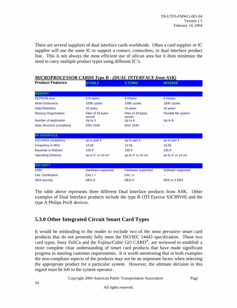
TR-UTFS-FMWG-001-04 Version 1.5
February 14, 2004
Copyright 2004 American Public Transportation Association Page
There are several suppliers of dual interface cards worldwide. Often a card supplier or IC supplier will use the same IC to support a contact, contactless, or dual interface product line. This is not always the most efficient use of silicon area but it does minimize the need to carry multiple product types using different IC’s. MICROPROCESSOR CARDS Type B - (DUAL INTERFACE from ASK) Product Features GTML2 CT2002 MV500X MEMORY EEPROM size 576 bytes 8 Kbytes 8 Kbytes Write Endurance 100K cycles 100K cycles 100K cycles Data Retention 10 years 10 years 10 years Memory Organisation Files of 29 bytes
record Files of 29 bytes record
Flexible file system
Number of application Up to 3 Up to 8 Up to 8 Data Structure (compliant) ENV 1545 ENV 1545 - RF-INTERFACE ISO14443 compliancy up to part 4 up to part 4 up to part 4 Frequency in MHz 13.56 13.56 13.56 Baudrate in Kbit/sec 105.9 105.9 105.9 Operating Distance up to 4” or 10 cm up to 4" or 10 cm up to 4" or 10 cm SECURITY SAM Hardware supported Hardware supported Software supported EAL Certification EAL1 + EAL 1+ - DES security DES-X DES-X DES or 3 DES
The table above represents three different Dual Interface products from ASK. Other examples of Dual Interface products include the type B OTI Eyecon S3C89V05 and the type A Philips ProX devices. 5.3.0 Other Integrated Circuit Smart Card Types It would be misleading to the reader to exclude two of the most pervasive smart card products that do not presently fully meet the ISO/IEC 14443 specification. These two card types, Sony FeliCa and the Fujitsu/Cubic GO CARD®, are reviewed to establish a more complete clear understanding of smart card products that have made significant progress in meeting customer requirements. It is worth mentioning that in both examples the non-compliant aspects of the products may not be an important factor when selecting the appropriate product for a particular system. However, the ultimate decision in this regard must be left to the system operator.
34 All rights reserved.
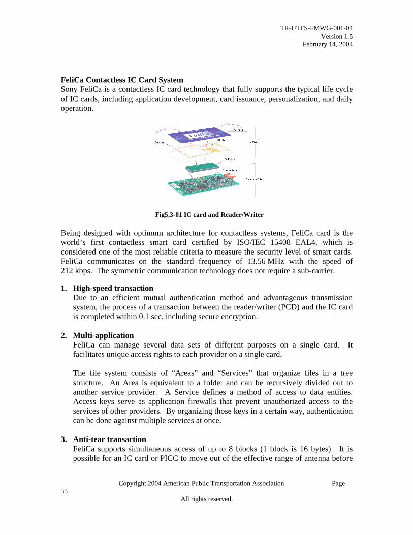
TR-UTFS-FMWG-001-04 Version 1.5
February 14, 2004
Copyright 2004 American Public Transportation Association Page
FeliCa Contactless IC Card System Sony FeliCa is a contactless IC card technology that fully supports the typical life cycle of IC cards, including application development, card issuance, personalization, and daily operation.
Fig5.3-01 IC card and Reader/Writer Being designed with optimum architecture for contactless systems, FeliCa card is the world’s first contactless smart card certified by ISO/IEC 15408 EAL4, which is considered one of the most reliable criteria to measure the security level of smart cards. FeliCa communicates on the standard frequency of 13.56 MHz with the speed of 212 kbps. The symmetric communication technology does not require a sub-carrier. 1. High-speed transaction
Due to an efficient mutual authentication method and advantageous transmission system, the process of a transaction between the reader/writer (PCD) and the IC card is completed within 0.1 sec, including secure encryption.
2. Multi-application
FeliCa can manage several data sets of different purposes on a single card. It facilitates unique access rights to each provider on a single card. The file system consists of “Areas” and “Services” that organize files in a tree structure. An Area is equivalent to a folder and can be recursively divided out to another service provider. A Service defines a method of access to data entities. Access keys serve as application firewalls that prevent unauthorized access to the services of other providers. By organizing those keys in a certain way, authentication can be done against multiple services at once.
3. Anti-tear transaction FeliCa supports simultaneous access of up to 8 blocks (1 block is 16 bytes). It is possible for an IC card or PICC to move out of the effective range of antenna before
35 All rights reserved.

TR-UTFS-FMWG-001-04 Version 1.5
February 14, 2004
Copyright 2004 American Public Transportation Association Page
completing the “write” process, resulting in data inconsistency. In such a case, the FeliCa card automatically discards incomplete data to restore the previous state.
4. Security
Using the industry standard security algorithms, FeliCa ensures a higher level of proven security. Triple-DES is used for mutual authentication (Fig.5.3-02). Transmission data is encrypted using CBC-mode single DES. The encryption key is dynamically generated every time mutual authentication is performed. Thus, it prevents fraud such as impersonation.
Figure 5.3-02. Mutual Authentication The transport key scheme provides a way to avoid fraud during the shipping and issuance process. 5. Advantageous characteristics for contactless system
FeliCa is designed with an optimum architecture for contactless systems. FeliCa adopted the Manchester system as a bit-coding scheme, which is tolerant of the noise caused by the distance fluctuation between the reader/writer and the card. Anti-collision is achieved by the Time slot method, which is simple with fewer steps per transaction than commonly used alternatives. The Symmetric communication employed by the card and reader does not use a sub-carrier. Thus spurious emission is low, and also communication speed could exceed 847kbs if allowed.
Carrier: 13.56 MHz (no sub-carrier) Modulation: ASK 10% Bit coding: Manchester Communication speed: 212 kbps (Fc/64) Anti-collision: Time slot
Table 5.3-01. Data sheet
36 All rights reserved.

TR-UTFS-FMWG-001-04 Version 1.5
February 14, 2004
Copyright 2004 American Public Transportation Association Page
6. Services Three types of built-in services are provided by the FeliCa operating system. Each service has multiple access modes, such as Read Only and Read/Write (Table 5.3-02). Each can also be configured with or without security.
Table 5.3-02. Services and access modes 5.4.0 GO CARD® The GO CARD® offers two unique products, consisting of either a 2KB or 32KB PICC or contactless memory logic integrated circuit for smart cards. They were designed for high performance transit, security, and biometric building access and logical system access. The integrated circuit makes use of FeRAM non-volatile memory technology from Fujitsu Corporation. The GO CARD® is unique in functionality because its well-established anti-tear design makes efficient use of the fast FeRAM technology. FeRAM operates with a symmetrical read and write cycle as opposed to EEPROM memory which is comparatively much slower in write access cycles. A typical EEPROM write cycle is 1.5ms as opposed to a FeRAM write cycle of <150ns. The GO CARD® has demonstrated typical transit transaction times in under 100msec. in systems in London, Washington DC, and Chicago. For security, each GO CARD® has its own unique serial number and one set of separate read/write keys per memory file. It performs secure message authentication for all data exchanges. Triple DES (3-DES) key diversification is accomplished via the reader and the host.
37 All rights reserved.

TR-UTFS-FMWG-001-04 Version 1.5
February 14, 2004
Copyright 2004 American Public Transportation Association Page
Today the GO CARD® is also implemented in NYCT and Sydney for secure vaulting applications. In addition, the cards are used for building access in Washington, DC and San Diego. The GO CARD® presently is North America’s most applied and used contactless smart card product for transportation applications. The GO CARD®, as with many other smart card products, was designed to work as a complete, integrated system of cards, readers, security, and hosting interfaces. The future of smart card development will benefit greatly by several technical accomplishments this advanced smart technology offers. Future revisions of the GO CARD® may include an ISO 14443 compliant type B smart card offering.
GO CARD® with Tri-Reader® 6.0 Non-IC Smart Card Technologies There are various electronic fare media technologies that offer functionality for the transit industry, but are not based upon integrated circuits. Many of these come in the form of a standard credit card size ticket and at times are mistakenly called IC smart cards. This section explores a few of the more popular alternatives to integrated circuit smart cards. 6.1.0 Capacitive Cards Capacitive card technology represents a growing fare media type being adopted by some agencies in the transit industry in search of an alternative to magnetic or paper tickets. Capacitive cards offer comparatively low cost, although the technology has limited fare media application since it is a “write once” technology.
38 All rights reserved.

TR-UTFS-FMWG-001-04 Version 1.5
February 14, 2004
Copyright 2004 American Public Transportation Association Page
6.1.1 Primary Capacitive Technology Capacitive cards contain an array of tiny micro-fuses laser-etched into a vacuum-sputtered tin layer laminated between two polyester card material layers. When the card is inserted into the reader, it is capacitive coupled to a sensor array, which can determine which fuses are connected. By this method, the card’s stored value can be read, including the geo-encryption and the authentication. Diagram 6-01 below represents the array of capacitive cells on the backside of a capacitive card from C-Card. Each fuse, or bit of memory, represents one unit of stored value, such as a bus fare, which may be debited from the card. When a purchase is made, selected fuses can be destroyed using an appropriate write voltage and frequency, which induces an electric current through the metallic micro-fuse sufficient to destroy it. As its name implies, geo-encryption is a method of using complex geometric patterns which, when laser etched into the card, result in security of transaction, an extremely important consideration for the issuer of both pre-paid cards and e-commerce cards. Each card is produced with its own unique serial number and digital signature for authentication. Unlike magnetic cards which interact with other electromagnetic fields and are, therefore, easily erased or fraudulently re-loaded, the information stored on the capacitive cards is stored in a non-interactive format and is encoded using proprietary geo-encryption. This security of transaction is an extremely important consideration for the issuer of both pre-paid cards and e-commerce cards.
Diagram 6-01 Capacitive Card Courtesy of C-Card
39 All rights reserved.

TR-UTFS-FMWG-001-04 Version 1.5
February 14, 2004
Copyright 2004 American Public Transportation Association Page
6.1.2 Secondary Capacitive Technology A second capacitive card technology is the patented “OneOnly” swipe reader, which features a small electronic head. When a card is passed over the reader, random capacitive cell patterns on the card, containing thousands of bits of information, are read. The pattern, once read, can then be used as an electronic “finger print” for authentication. The unique signature captured by the head is represented by a three-dimensional analog wave, which makes the signature impossible to reproduce. This “OneOnly” security feature can be used to create swipe cards with counterfeit protection as a complementary technology to magnetic stripe credit cards. 6.1.3 Capacitive manufacturing and encoding Capacitive cards are constructed by encapsulating sputtered metalization between sheets of protective polyester. This material is then slit or sheeted in preparation for printing and die cutting. The equipment shown below is used to laser-etch special patterns into the metal layer of each card, which are interpreted as a stored value with a digital signature.
Courtesy of C-CARD Corporation
Diagram 6-02 Capacitive Card Encoding Machine
40 All rights reserved.

TR-UTFS-FMWG-001-04 Version 1.5
February 14, 2004
Copyright 2004 American Public Transportation Association Page
The reader/writer is constructed of a single printed circuit board with no moving pieces, using capacitive coupling with the laser-etched pattern on the card to authenticate and process the value. Billions of unique patterns act similar to a fingerprint, authenticating the card by deriving the unique serial number and digital signature on each card, before deducting the value. This provides for unprecedented security at volume pricing of around twenty cents per card. Capacitive cards (generally) cannot be re-loaded, are extremely difficult to counterfeit, and are relatively durable because of their immunity from magnetic fields, static electricity and the more mundane but more likely damage resulting from scratches or an accidental trip through the washer and dryer. Diagram 6-02 above represents a capacitive encoder. 6.3 Optical Cards An optical memory card can be a secure and durable data storage card, which is read using a laser light. This technology is often applied to an ISO standard ID-1 credit card format, which allows it to be carried easily by the user. An optical memory card may have a storage capacity equivalent to that needed for storing an average size textbook. Currently the total capacity is between 4.0 and 6.0 megabytes, which results in a useable capacity of nearly 2.8 to 4.0 megabytes. This is enough capacity to store digital files with thousands of pages of text, or up to 200 scanned pages.3 Even with this large storage capacity, the process of filling the card with perforated storage holes by the laser encoder will eventually fill up the card and it will have to be replaced. Optical write once, read many (WORM) recording ensures that files and data stored on optical memory cards are also secure and safe against tampering, deletions or accidental loss. Files and data on the card can be added to or modified, but not deleted as with a Read-Write CD. When files are added or modified, a permanent audit trail of all access and changes is automatically recorded on the optical media. And because it is an optical device, the card is not affected by magnetic or electrostatic fields and can withstand temperatures of up to 212°F. Optical media, however, is subject to surface damage such as scratches and foreign debris. Optical memory cards use the same technology made popular by audio compact discs and audio-visual CD-ROM products. Users write on the card with a narrowly focused, high intensity laser beam. A low-power light beam is used to read the physical spots or “pits” created during the writing process. Optical memory cards are the ideal solution for applications requiring low-cost, durable, secure and comprehensive offline data storage and transportation. Thus, this type of card
3 www.frontlinemagazine.com/card-t.htx; Frontline Solutions, Card Technologies, ©Advanstar Communications
41 All rights reserved.

TR-UTFS-FMWG-001-04 Version 1.5
February 14, 2004
Copyright 2004 American Public Transportation Association Page
is ideal for record keeping, such as medical files, driving records, or travel histories.4 Optical memory cards can include color thermal printing, a magnetic stripe, an IC chip and customized security formats. These features also make optical memory cards a highly secure identification. ISO/IEC 11693 and 11694 define standards for optical memory cards. The optical media is encapsulated between transparent, protective layers of polycarbonate plastic. To record data, an optical card drive uses a laser to burn physical spots on the reflective optical media, similar to CD-ROM recording technology, but with the ability to add more data at any time. These spots or small holes burned onto the media create certain patterns that signify the presence or absence of a hole, which in turn indicates a 1 or a 0. The spots are microscopic in size - as small as 2.25 microns. The smallest size spot the human eye can see is about 20 microns.5 Since it utilizes digital technology any type of digital information can be stored on the card For example, although it is only the size of a consumer credit card, the LaserCard® optical memory card, as well as other brands, have a digital data storage capacity of book-size proportion. This optical card has about 350 times the capacity of the 8kb integrated circuit (IC) chip card. The high storage capacity of the card allows for the addition of other applications as the need arises without interfering with the original data stored on the card. For example, ten independent data areas can be partitioned on the card, with each one holding about 250kb of data. This enables different departments, agencies, or commercial groups to use their own section, independent and secure from other departments, agencies, or groups.6 High-security features inhibit counterfeiting and data tampering and provide controlled access to the rights granted by the card. The card is primarily used as proof that the cardholder or user has formal permissions, privileges, or rights from the card issuer. These cards are used for immigration, visas, pay-per-use systems, ID/access, cargo manifests, motor vehicles, healthcare, and other digital read/write wallet-card applications.7
To use the optical card, it must be inserted into a reader that is similar to a disk drive, where the reading and writing takes place. The card’s read and write device skims over the surface of the medium to read from or write to the card. Although this technology boasts a very fast seek time with high security features, this technology may not yet be suited for public transit applications where the environment is subjected to heavy
4 www.ewh.ieee.org/r10/bmbay/news5/SmartCards.htm; Smart Cards 5 www.lasercard.com/tech/wrdata.htm; Writing and Reading Data 6 www.lasercard.com/tech/datastorage.htm; Data Storage Capacity 7 www.globalmanufacture.net/home/news/card.cfm; Drexler Technology Gets Million-Card Order; 8 Million LaserCard Holders in North America, Growing by 300,000 Per Month, Mountain View, California—(Business Wire)—March 22, 2001
42 All rights reserved.

TR-UTFS-FMWG-001-04 Version 1.5
February 14, 2004
Copyright 2004 American Public Transportation Association Page
vibration. If it were to be installed into a fare box, the movement of the bus could throw off the movement of the read/write head, causing data errors. 7.0 Magnetic Cards Magnetic technology is still the most pervasive electronic fare media used in transportation systems. Over time, magnetics have improved upon their overall systems costs (i.e.: Acquisition, operation, etc.) and have also steadily improved product reliability. At the same time magnetic ticket bit storage density and transactional performance have also improved. Since there continues to be significant investment and technical improvements for this tried and true technology, it is most likely that magnetic systems will continue to be in use for years to come. This section reviews many of the key attributes of magnetic fare media and is further explored in the Trends and Futures section of this document. 7.1.0 Theory Magnetic Tape As early as 1898, Valdemar Poulsen discovered that an iron wire could be magnetized and could store information. He demonstrated this process with his “telegraphone” at the Paris World Fair in 1900. Shortly afterward he showed how he could record and play back a voice message. In the 1920’s, the Germans sold tape recorders that used steel tape, and in 1928, they filed a patent describing how iron particles coated onto paper could form a recording surface. Without getting into heavy technical material (which is beyond the scope of this document), it is sufficient to say that gamma ferric oxide (similar to rust) is frequently used as a magnetic material for recording information. This oxide is combined with various solvents and binders and formed into slurry that is coated onto paper or plastic backing material. There are other alloys often used; as an example, barium ferrite is used for high-coercivity tape. The microscopic needle-like iron oxide particles, acting like tiny bar magnets, are laid end to end on the tape. Each particle has the property of having a “north” and “south” magnetic pole on opposite ends of the particle. An external magnetic force may be applied in either of two directions and thus determine the polarity of the particle (which end is north and which is south). A magnetic-encoding head, also known as a recording or write head, is a sophisticated electromagnet made by winding many turns of very fine wire on an iron core. The core has a gap that allows the magnetic field to escape and to penetrate the iron oxide on the tape. As the encoding head is passed along the length the tape, the electrical current flowing in the windings of the encoding head are periodically
43 All rights reserved.

TR-UTFS-FMWG-001-04 Version 1.5
February 14, 2004
Copyright 2004 American Public Transportation Association Page
reversed, resulting in bands of alternating magnetic polarities on the tape. The changes in polarity are what stores the data on the tape. 7.1.1 Magnetic Tape Foil Manufacturing While the process of producing magnetic tape is conceptually simple, the components and specific procedure are exacting. The magnetic particles are purchased dry from the supplier. The magnetic particles are like individual bar magnets and tend to stick together in lumps, which would prevent production of a uniform coating on the tape. The first step, therefore, is to grind the lumps into a fine powder. The lumps and solvents, which dilute and disperse, are placed into a ball mill, which is a large rotating container. The rotational movement of the ball mill induces a grinding action to separate the lumps. The particles are dispersed evenly within the mixture. Now, depending upon the recipe, additional solvents, stabilizers, binders, plasticizers, lubricants, and conductive agents are added. Milling is continued until particles are coated and uniformly dispersed. The mixture is often called a slurry. Incomplete dispersion of the particles and incorrect viscosity of the solution can produce various tape problems, such as an uneven coating, signal level variations, poor resolution, noise, etc. After the slurry is completely milled, it is moved to the coating machine. The slurry must be coated onto a base film, usually made of polyester material. Typical methods of application are reverse roll coating, knife coating, or gravure coating. Within the wet coating, low coercivity needle-like magnetic particles (high coercivity particles are platelet shaped) are oriented in random directions. For magnetic stripe applications, the particles must be oriented parallel to the edge of the tape, that is, pointing in the direction of tape motion. Otherwise, signal strength and quality would be dramatically reduced. After coating, the particles are oriented with a magnet. Finally, the tape is passed through a drying oven where the solvents are boiled off and the coating dried. After drying, the tape is slit into strips of the appropriate width. 7.1.2 Magnetic Ticket Size8 Card dimensions and tolerances (Card Size ID-1) All points on the edges of the card in the finished state, except for the rounded corners, must fall between two concentric, similarly aligned rectangles as defined in Figure 7-01 for maximum height and width, and minimum height and width. The corners must be
8 Note that many variations of magnetic ticket size exist in the industry.
44 All rights reserved.

TR-UTFS-FMWG-001-04 Version 1.5
February 14, 2004
Copyright 2004 American Public Transportation Association Page
rounded with a radius as specified in Figure 7-01. Care should be taken to avoid misalignment between the rounded corners and the straight edges of the card. The thickness of a card as defined here applies only to those parts of the card outside of any raised area. An example of such a card is the NYCT’s Metro Card depicted below.
Figure 7-01 New York City Metro Card
45 All rights reserved.

TR-UTFS-FMWG-001-04 Version 1.5
February 14, 2004
Copyright 2004 American Public Transportation Association Page
d
c
b
Top reference edge
aLeft edge
Front of card
dimensions in millimetres (inches)
a b c d
Max Mi Max Min Max Min Max Min
85.72 85.47 54.03 53.92 3.21 3.15 0.84 0.68 (3.375) (3.365) (2.127) (2.123) (0.137) (0.113) (0.033) (0.027)
Figure 7-02 — Card dimensions
Card edges Edge burrs normal to the card face must not exceed 0.08 mm (0.003 in) above the card surface. 7.1.3 Magnetic Ticket Size (Example)
46 All rights reserved.

TR-UTFS-FMWG-001-04 Version 1.5
February 14, 2004
Copyright 2004 American Public Transportation Association Page
TFC-0, TFC-1, TFC-5:
7.1.4 Magnetic Ticket Materials See ISO documents
15457 Thin Flexible Cards (attached) 7810 ID-1 Physical Characteristics (attached)
7.1.5 Testing Magnetic Cards Testing Mag Stripe Tickets and Readers Magnetic Stripes have been used on plastic cards and tickets since the late 1960’s, and now serve every aspect of plastic and paper card data-carrying requirements in almost all forms of card applications. This is a mature technology.
47 All rights reserved.

TR-UTFS-FMWG-001-04 Version 1.5
February 14, 2004
Copyright 2004 American Public Transportation Association Page
A lot of new magnetic technology has been developed since the magnetic stripe was first put onto a card. As examples, high-coercivity, colored magnetic stripes, secure magnetic stripes, and high-density magnetic stripes have all been introduced in the last two decades. All of these technologies add performance enhancements over and above what was offered by the original magnetic stripe cards. With the addition of these new magnetic stripe technologies there are increasing requirements for greater reliability and durability of the magnetic stripe tickets and cards in most applications. The only way to verify that new magnetic stripe technology meets the higher performance levels required by modern transit systems is through testing and analysis. Magnetic Stripe Media and Ticket Testing If you are a ticket manufacturer or user, you must test your magnetic stripe and ticket quality. Only through the execution and documentation of such testing can you confirm that the product meets the minimum specifications. There are several magnetic stripe testing and magnetic stripe analyzer systems on the market from which to choose. Some of the important criteria in choosing a magnetic stripe analyzer system are:
1. The magnetic stripe analyzer must meet or exceed industry standards and specifications and must facilitate reliable and repeatable testing.
2. Ticket and card alignment within the test fixture must be a simple and easily repeated process.
3. The system should feature an easily accessed magnetic head. If you cannot access the ticket-to-magnetic head contact area easily during operation of the system, it will not be possible to determine if the magnetic head is in the correct orientation and near contact with the magnetic stripe. Improper orientation of the magnetic head to the magnetic stripe can lead to failed tests or misleading test results.
4. The magnetic heads in any testing system are the most critical component to ensure reliable testing. The magnetic heads must be located where they can be easily and quickly inspected. Ideally, the magnetic heads should be located on the top of the unit to allow for easy access for inspection, cleaning, adjustment, and replacement. On any magnetic stripe analyzer, maintenance must be performed on a regular basis to ensure the accuracy and performance of the magnetic stripe analyzer. Some testing systems use an enclosed architecture, which requires shipping the unit to the manufacturer or a service facility for maintenance, resulting in several weeks of downtime and high shipping costs. Figure-03 is an example of an open architecture magnetic analyzer.
48 All rights reserved.
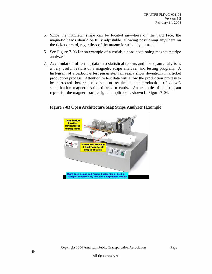
TR-UTFS-FMWG-001-04 Version 1.5
February 14, 2004
Copyright 2004 American Public Transportation Association Page
5. Since the magnetic stripe can be located anywhere on the card face, the magnetic heads should be fully adjustable, allowing positioning anywhere on the ticket or card, regardless of the magnetic stripe layout used.
6. See Figure 7-03 for an example of a variable head positioning magnetic stripe analyzer.
7. Accumulation of testing data into statistical reports and histogram analysis is a very useful feature of a magnetic stripe analyzer and testing program. A histogram of a particular test parameter can easily show deviations in a ticket production process. Attention to test data will allow the production process to be corrected before the deviation results in the production of out-of-specification magnetic stripe tickets or cards. An example of a histogram report for the magnetic stripe signal amplitude is shown in Figure 7-04.
Figure 7-03 Open Architecture Mag Stripe Analyzer (Example)
49 All rights reserved.

TR-UTFS-FMWG-001-04 Version 1.5
February 14, 2004
Copyright 2004 American Public Transportation Association Page
Figure-7-04 Histogram of Signal Amplitude
FFrreeqquueennccyy DDiissttrriibbuuttiioonn
0 .1 1 0 .1 2 0 .1 3 0 .1 4 0 .1 5 0 .1 6 0 .1 7 0 .1 8 0 .1 9 0 .2 0 0 .2 1 0 .2 20
2 0
4 0
6 0
8 0
1 0 0
1 2 0
N u m b e r o f C a rd s W ith in M a g S tr ip e D is ta n c e R a n g e
Car
d C
ount
s
T o p o f C a rd to T o p o f M a g S tr ip ein in c h e s
The magnetic stripe analyzer should be usable by a production technician as well as a process engineer. Having multiple layers or menus of testing screens and data reporting options facilitates usability of the system. Another example of features which increases usability, is having a test data summary for the technician, and having complex data analysis of the same parameter for the process engineer, enabling “go-no-go” decisions. Calibration and Test Tickets and Cards for Systems Testing As part of an overall program of magnetic stripe quality it is necessary to check the magnetic stripe readers that are part of the magnetic stripe application. For example, a ticket-terminal manufacturer will need to determine how well their decoding electronics handle the two most important parameters of a magnetic stripe, the signal amplitude variation and encoded data spacing variation (jitter). This is true of any system that contains both the magnetic stripe ticket and the magnetic stripe reader; both have to be tested. The best way to test magnetic stripe readers is with magnetic stripe test cards that have specific parameters set to predetermined points. For example, a jitter test ticket or card could have the jitter set to ±25% to see how well the decoding electronics determines the difference between a binary zero and a binary one. Another test card might have a signal amplitude at 60% of the ISO reference amplitude. This would be used to determine how well the gain or amplification of the reader handles low amplitude cards. In addition to having a magnetic stripe analysis program and using a series of test and calibration cards in your production, you may need to have a third party magnetic stripe testing service help you examine, interpret, and understand specific problems with
50 All rights reserved.

TR-UTFS-FMWG-001-04 Version 1.5
February 14, 2004
Copyright 2004 American Public Transportation Association Page
magnetic stripe cards. There are several testing service laboratories that can perform the basic ISO testing and, in some cases, more extensive tests. 7.2.0 Magneprint Banks, which use the existing credit card terminal infrastructure are currently testing a Magnetic Stripe Fraud detection system. The system is meant to detect counterfeit credit cards by reading the unique magnetic “fingerprint” on the stripes of credit cards. The system is called Magneprint, which is being developed by Magtek, Inc. There have been several pilots of the technology; the most recent pilot is currently taking place city-wide in Kuala Lumpur, Malaysia. Magneprint technology takes advantage of a unique and inherent property of magnetic stripes. Each magnetic stripe on a credit card has millions of magnetic particles that form a unique “noise” pattern. The noise pattern can be read as a Magneprint (fingerprint) image. Because the noise pattern is a unique, inherent property of the stripe material, it cannot be duplicated or copied. Furthermore, the Magneprint image derived from the noise is also strongly related to the data recorded on the magnetic stripe. This combination uniquely matches the card data with the Magneprint image, which allows discovery of either a copied card or any change of data on a card. The system works by reading the Magneprint image of each newly issued card. The image is stored in the same computer database used to accept credit card transactions. Each time the card is used in a terminal with Magneprint capability, the card data and the card Magneprint image are read and can be compared to the database information. If the comparisons are different the transaction can be rejected. The pilot testing of more that 600,000 terminal transactions in Malaysia have clearly demonstrated that the bank computer systems can easily discriminate between an original issued card and a card copied from the original. While such a technology could have valuable applications in transportation, comparison to a centralized database in real-time might not be practical in most modern transit systems. 7.3.0 Extended Life Magnetic Heads Dirt and Wear Resistant Magnetic Head and Coatings Magnetic heads installed in equipment used for fare collection in subways and toll roads are subject to very extreme conditions. The magnetic head must be capable of functioning normally under extremes of temperature, humidity and dirt. It is required to read several million tickets or cards that may have been supplied to the agency by the lowest bidder or bidders. Magnetic stripe quality and the card or ticket surface of the media can be abrasive and destructive to the magnetic heads. Magnetic heads must read and write a variety of media from lower quality paper tickets with magnetic ink to higher
51 All rights reserved.

TR-UTFS-FMWG-001-04 Version 1.5
February 14, 2004
Copyright 2004 American Public Transportation Association Page
quality plastic tickets with laminated magnetic tape. These are factors that must be considered in the selection of the magnetic head core material and the magnetic head coating. When the magnetic-stripe-based fare collection systems first evolved, the magnetic media consisted of primarily paper tickets with a magnetic-ink slurry or foil. These tickets were generally used either one time or a limited number of times and discarded. The abrasive nature of the tickets was a concern and, in some systems, the magnetic heads stopped functioning after 50,000 passes (tickets). To increase the durability of the magnetic heads, each was plasma coated with various types of ceramic, and product life was extended to 500,000 passes. Brush (a leading supplier of products for magnetic ticket and card systems) developed a long life core material (Supermium™) that, when coupled with ceramic coating, extended life to 5,000,000 passes. Supermium™ hard-core material had an additional benefit of reducing a phenomenon called scalloping that shortened magnetic head performance through spacing losses. This is a phenomenon that causes the gap between the magnetic head and the ticket or card surface to increase over time, resulting in sporadic loss of physical contact with the magnetic media, that resulted in read and write errors. As systems and software have evolved and become more capable, transit authorities have extended their systems’ capabilities. Authorities now have systems that use stored value cards, time-based cards, trip-based cards, plastic cards, and paper tickets. In addition, many systems must cope with different ticket (card) thickness, from paper and plastic tickets as thin as 0.007 inch to as thick as 0.033 inch for plastic cards, such as those used for credit cards. In some newer systems, paper tickets are no longer used and reusable plastic tickets have become the norm. Many systems provide the capability for patrons to check the stored value on their card, reload value, and to pay fares with a reusable card or ticket product. In many instances, systems have become inter-modal and the same card can be used to pay for rides on two or more different forms of transit, i.e., subway, ferry, light rail, bus, etc. The magnetic heads in more complex systems are required to read cards with greater amounts of stored data, re-write the card with new data, and verify what has been re-written in a matter of seconds. At high traffic turnstiles, this process can occur over 3,000 times a day. In recent years a new type of magnetic media, High Coercivity (or “HiCo”), was introduced that is much more durable and more secure to encode. HiCo magnetic stripes are now used on most new systems. With the combined impacts of multiple use ticketing and more stringent read and write requirements, accumulation of foreign debris on the magnetic heads can become more of a reliability issue. In some instances, a build up of a tar-like substance appears on the magnetic heads, causing read and write errors due to spacing losses. Note: In some older systems paper tickets were used. Paper can be a
52 All rights reserved.

TR-UTFS-FMWG-001-04 Version 1.5
February 14, 2004
Copyright 2004 American Public Transportation Association Page
slightly absorbent material, causing dirt and other foreign materials to stick to the ticket. This, along with the abrasive slurry media, produces a cleaning effect on the magnetic heads. Laboratory analysis of the material indicated it was a mixture of body oils, dirt, metal rail dust and other substances (such as oils found in cosmetics and greasy foods). In order to maintain the desired performance of the magnetic heads, more frequent cleaning is required, resulting in increased maintenance costs and, if such cleaning is not performed, reduced system performance. One key example of this problem is a very large system that requires patrons to swipe their magnetic cards rather than using some form of ticket or card transport. The swipe reader is mounted on the top of the gate and the card is read, re-written, and verified in one swipe motion. The system uses a 10-mil thick plastic card, which can be used many times, re-loaded, or turned back in for re-issue. If the transaction is successfully completed, the turnstile unlocks and the patron is allowed to pass through. If the transaction is not successful due to a mis-swipe (an incomplete or improper swipe motion), the patron is asked to swipe again. On-site observations and examination of the readers determined that dirt was building up on the top and trailing edge of the magnetic head. After a certain amount of dirt accumulated on top of the head, the system started to experience a higher percentage of read/write errors. If the unit is not cleaned, the magnetic head eventually fails to perform any read or write functions, since the whole top surface of the head becomes covered with debris. Various experiments with magnetic head designs and coating materials at test sites throughout the world over the last two years has resulted in the development of a new head coating material and a new head design. These products have demonstrated significant improvement over the originally installed Standard Magnetic Head, which has an Aluminum Dioxide Titanium Trioxide Ceramic Coating. The new coating material is called “CoMoly” and the head Design is bridged. CoMoly is a non-ceramic hard plasma coating material containing Cobalt, Molybdenum and Chromium. This is a material that is adaptable for longwearing, low friction applications. 8.0 Processing, Printing, and Encoding of Magnetic and Smart Cards There are several smart card or magnetic encoders now available on the market. These are categorized into two types: low production and high production, referring to the volume of cards that can be produced each hour. A low production encoder typically will require some degree of manual processing and will encode a maximum of 150 cards per hour. A high production encoder often integrates other features, such as stress testing
53 All rights reserved.

TR-UTFS-FMWG-001-04 Version 1.5
February 14, 2004
Copyright 2004 American Public Transportation Association Page
and blister packaging. This encoder-type encodes cards at an average rate of over 1000 cards per hour. Keep in mind that the type of card and size of the encoded file(s) can have a significant effect on the actual throughput, regardless of the encoder type used. In most cases, low production encoders are used in a ticket booth, vending machine or at the issuance office, where personalization of the card takes place. High-speed encoders usually reside in the back rooms of the issuer and or transit agencies. Below is an example of a high-speed magnetic card, smart card, or combination card configurable encoder. This encoder offers stress testing, serial number and batch or lot printing, blister packaging, central reporting and tracking of all encoded smart cards. This type of encoder can also be converted to either a smart card or magnetic strip encoder. Figure 8-01 is one example of a High Speed Processing and Encoding Machine for magnetic tickets or smart cards.
Courtesy of Cubic Corporation
9.0 Data Formats This is a highly debated subject matter that offers a variety of approaches to support the transit industry’s requirements for electronic fare media processing. Data formats are important in providing interoperability and consistent operation of electronic fare media, especially in the case of smart cards. A smart card’s data format consists of Records, Files and Data Elements. It is important that each of these items is carefully thought out to ensure the best memory utilization and overall system performance that meet the specific system requirements. This document offers one example of a method or approach to formatting data within a smart card, as seen below, in the Issuer Record Format Table 9-01. The process of
54 All rights reserved.
TR-UTFS-FMWG-001-04 Version 1.5
February 14, 2004
Copyright 2004 American Public Transportation Association Page
achieving transit industry standardization and acceptance for data format is still in debate and will most likely not be standardized for years to come.
55 All rights reserved.

TR-UTFS-FMWG-001-04 Version 1.5
February 14, 2004
Copyright 2004 American Public Transportation Association Page
Table 9-01 Smart Card Issuer Record Format Table (Example) Byte Data Element Description Value Bit Size 0 DataFormat Data Format
Version 0-3 2
0 Test Ticket Indicator0=Revenue, 1=Test
0-1 1
0 Spare 1 Set to zero default
0-1 1
0 Country ID ID for currency and country: 0=UK 1=USA 2=Germany 3=France 4=Canada 5=Mexico 6=Italy 7=Japan
0-15 4
1 Regional ID Transit Region 1-255 8 2 Card-Type/Version
Code Pointer See Table-2 1-255 8
3 Spare-2 Set to zero default
0-7 8
4 IssuerID Card Issuer 1-255 8 5-6 Date Pointer Expiration or
Issuance 1-31= day 1-12= month 0-99 = year
16
7-8 Date of Birth Card Holder dd/mm/yy 16 9 UserClassCode Card Holder
Class 0=Public 1=Employee
0-1 1
9 ClassDiscountCode Type of discount applied
0-127 7
10 UserPreRegistration Registration Enabled
0-1 1
56 All rights reserved.

TR-UTFS-FMWG-001-04 Version 1.5
February 14, 2004
Copyright 2004 American Public Transportation Association Page
Byte Data Element Description Value Bit Size 0=no 1=yes
10 CardValidityPeriodCode
Coded pointer to card’s valid period
0-7 3
10 DepositPaid Deposit Paid Amount
0-15 4
11-12-13 PrintedSerialNumber Unique Serial Number Printed
0-16,777,216 24
14-15 CRC CRC 0-65535 16 9.1 Calypso The French team consisting of the RATP, SNCF, and Innovatron Corporation created Calypso™, a contactless smart card technology standard. This was a ten-year development program that defined and implemented the smart card contactless technology and adapted it for use in public transportation. The technology was made available to industry supplier companies under license agreements. The Calypso system consists of compliant smart cards within the ISO 14443 type B mode, security modules, readers, central system tracking software, compliant and certified end equipment, and support. Even though Calypso was originally intended for implementation for French public transportation systems in France, it has succeeded in other transit applications outside of France. Figure 9-01 below provides a graphical illustration of the methods and international standards that were used to create the Calypso system.
57 All rights reserved.
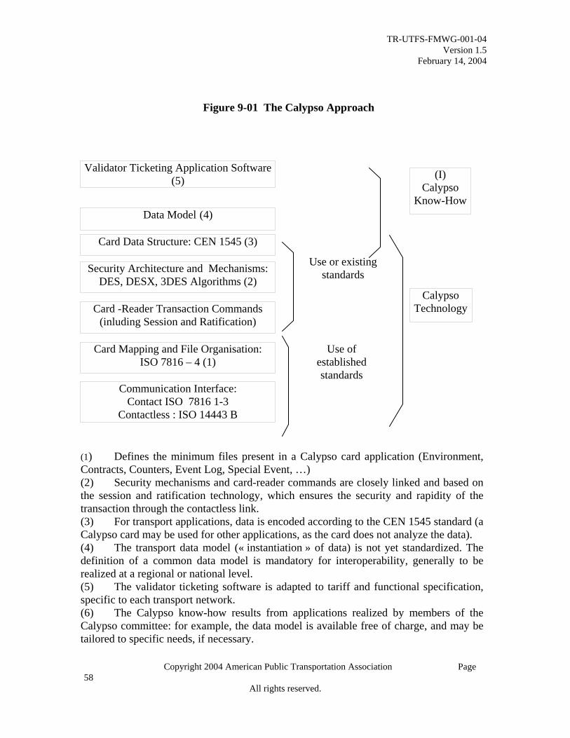
TR-UTFS-FMWG-001-04 Version 1.5
February 14, 2004
Copyright 2004 American Public Transportation Association Page
Figure 9-01 The Calypso Approach
Validator Ticketing Application Software (5)
Data Model (4)
Card Data Structure: CEN 1545 (3)
Security Architecture and Mechanisms:DES, DESX, 3DES Algorithms (2)
Card Mapping and File Organisation: ISO 7816 – 4 (1)
Communication Interface: Contact ISO 7816 1-3
Contactless : ISO 14443 B
Card -Reader Transaction Commands (inluding Session and Ratification)
(I) Calypso
Know-How
Use or existing standards
Calypso Technology
Use of established standards
(1) Defines the minimum files present in a Calypso card application (Environment,Contracts, Counters, Event Log, Special Event, …) (2) Security mechanisms and card-reader commands are closely linked and based on the session and ratification technology, which ensures the security and rapidity of thetransaction through the contactless link. (3) For transport applications, data is encoded according to the CEN 1545 standard (a Calypso card may be used for other applications, as the card does not analyze the data). (4) The transport data model (« instantiation » of data) is not yet standardized. The definition of a common data model is mandatory for interoperability, generally to be realized at a regional or national level. (5) The validator ticketing software is adapted to tariff and functional specification,specific to each transport network. (6) The Calypso know-how results from applications realized by members of the Calypso committee: for example, the data model is available free of charge, and may betailored to specific needs, if necessary.
58 All rights reserved.

TR-UTFS-FMWG-001-04 Version 1.5
February 14, 2004
Copyright 2004 American Public Transportation Association Page
9.2 ITSO ITSO™ was established in the United Kingdom under a grant from the Queen of England to pursue a common smart card environment for the United Kingdom. It is also the ITSO program owners’ desire to promote ITSO outside of the United Kingdom.
The program owners of ITSO hold a keen interest in the security of cards, products, and transaction data between inter-operable schemes. While ITSO does not run schemes, provide equipment, or influence commercial agreements, it does provide an environment for schemes to operate in and enjoy that security. A significant part of ITSO is the interoperable security solution, certification, and data format and management approach to smart card application environments. ITSO offers license and membership agreements to take advantage of this smart card environment. Figure 9-02 below illustrates the building blocks that make-up ITSO.
Figure 9-02 The ISTO Approach
59 All rights reserved.

TR-UTFS-FMWG-001-04 Version 1.5
February 14, 2004
Copyright 2004 American Public Transportation Association Page
9.3.0 ITSO and CALYPSO Collaboration The promoters of the ITSO™ and Calypso standards have agreed to jointly investigate their respective systems and procedures with a view toward:
Acceptance of the Calypso cards into the ITSO specification as (initially) an optional addendum;
Promotion of the ITSO™ specification and services by Calypso, where the ITSO scheme provides elements over and above the Calypso scheme; and
Collaboration with input to the CEN and IOPTA standardization process. To achieve the above, the two companies will embark on a phased investigation process, as follows. Phase 1 – A technical level review of the two schemes to establish the feasibility of adding the Calypso SAM functionality into the ITSO SAM, and having only the resulting one SAM in the terminals. In addition, the team will investigate if the ITSO Security Management Service could be used to centrally manage the Calypso keys; Phase 2 – An examination of the data structures within the ticket types from both schemes and the effect of inclusion of Calypso transactions in the ITSO data flows; Phase 3 – Possible extension of the ITSO accreditation scheme to include Calypso; and Phase 4 – Review of the business and commercial aspects of each scheme in order to define the final collaboration. 9.4.0 New York & New Jersey Regional Smart Card System Under the direction of the Port Authority of New York and New Jersey, and with the support of the other regional transit authorities and their consultants, a proposed specification was written to create a regional standard for PICC payment systems. This specification, known as the Regional Interoperability Standard (RIS), was released for industry comment in December, 2003. The primary purpose of the RIS is to provide an open specification for implementation of a regionally interoperable smart card system. As this specification matures, with the necessary modifications to allow for system performance and functionality that is expected by the transit industry, it will be a strong candidate for North American national transit standardization in coordination with
60 All rights reserved.

TR-UTFS-FMWG-001-04 Version 1.5
February 14, 2004
Copyright 2004 American Public Transportation Association Page
APTA’s UTFS standards and guideline efforts. Table 9-03 below summarizes the various parts of the RIS being developed to create this potential standard.
61 All rights reserved.

TR-UTFS-FMWG-001-04 Version 1.5
February 14, 2004
Copyright 2004 American Public Transportation Association Page
Table 9-03 The Port Authority of NY & NJ’s Regional Interoperability Standard
Part 1 User’s Guide User or implementer support for Parts 2-5.
Part 2 PICC, PCD and CID Physical Specification
Standard addressing the physical aspects of the PICC, PCD and CID.
Part 3 PICC, PCD and CID Software and Protocol Specification
Standard addressing the software format aspects of the PICC, PCD and CID.
Part 4 Central Management Specification
Specification to address the communication to and from the back-end processing systems and WEB services.
Part 5 Security, Test and Certification
Addresses the process necessary to achieve compliance to the RIS standard.
9.5 MTC TransLink® Regional Smart Card Specification The TransLink® program was developed under the direction of the Metropolitan Transportation Commission (MTC) to provide a regional transportation interoperable smart card environment for agencies and patrons in the San Francisco Bay Area. In the first quarter of 2002, TransLink launched a pilot demonstration system with nearly full functionality and card acceptance at six separate participating agencies. The system approach was designed to accommodate the full complement of smart card and system specifications and overall regional services that are (to be) required to achieve total interoperability. The specification defined a central point of card issuance, distribution, certification, accountability, customer support, procurement, asset management, and support services. The business model consisted of the various transit agencies paying a central organization to provide all the services believed necessary for a regional system. This model matches and expands upon the role a bank or credit card organization plays in supporting retailers with a common credit card acceptance system. The following set of bullets lists the key elements included within the scope of this specification.
• Card Issuance • Technical Interface Requirements • Card Type Specifications • Operational Procedures • Card Procurement
62 All rights reserved.

TR-UTFS-FMWG-001-04 Version 1.5
February 14, 2004
Copyright 2004 American Public Transportation Association Page
• Card Inventory Management • Distribution Services • Card-Base Management • Distribution Device Network Management • Fare payment Device Network Management • Financial Settlement • Reporting Services • Cardholder Support Services • Technical Support and Maintenance • Asset Management
The final report from the pilot demonstrated indicated that the TransLink system could support multiple fare policies in a multi-agency environment. 10.0 Actual Case Studies of Fare Media Implementations The number of transit agencies that have integrated electronic fare media into their system is still a relatively low percentage. However, that percentage is increasing on a yearly basis. An even lower percentage of transit agencies have integrated or updated their fare collection system from one type of electronic fare media to another. Two case studies, written by transit agency professionals, are provided below to broaden the reader’s appreciation and knowledge of the challenges of integrating two or more different types of electronic fare media. Note: The latest market research indicates that between thirty-five and fifty transit agencies have implemented, to varying degrees, smart card systems as of the year 2001. Chicago Case Study The Benefits of a Joint Magnetic Ticket and Smart Card System Background A transit agency has decided to migrate from a cash only fare payment system (with ticket agents) to an automatic fare collection system, which accepts cash, coins and electronic tickets. The fare media products included: magnetic polyester tickets with a slurry magnetic stripe, paper tickets with a PVC-tape stripe, and contactless smart cards (PICCs). The transit agency implements the AFC system with magnetic tickets only but has procured the software necessary to accept smart cards for later implementation. The AFC system is a two-phased installation. In the first phase, bus fare boxes and rail turnstiles were installed. (Exclusive of ticket agent lanes.) In the second phase, AVMs and agent lane turnstile were installed. During the turnover period, the transit agency
63 All rights reserved.

TR-UTFS-FMWG-001-04 Version 1.5
February 14, 2004
Copyright 2004 American Public Transportation Association Page
managed overlapping fare payment systems as the new automated system became more familiar to customers and employees. Introducing the Smart Card As the transit agency moved forward, the need to expand fare payment options for its customers became more important. A small, smart card test group was established to obtain new market data. This data was used to formulate policy for a full, system wide smart card product rollout. Key policy discussions included: Policy Issues Integrated Fare Payment System Although there are numerous transit systems that offer multi-modal transit services, only a few have an inter-modal fare payment system. Even fewer can support inter-agency payments and, correspondingly, regional interoperability. Different fare media products may be accepted within a single mode and, separately, between two or more modes of transportation. However, the level of service available by fare media product and mode can vary. Further, depending on the fare media product in use, the service gap can widen based on the product’s technology. While transit agencies may want or are being mandated to implement multi-modal and multi-agency fare systems, they must first face the challenges and limitations imposed by the integration of equipment i.e., AVMs, turnstiles, fareboxes, varying modes (i.e., heavy rail, light rail, and bus) and fare media (i.e., paper tickets, flash passes, magnetic tickets, and smart cards) as well as networking, settlement and ongoing support issues which complicate the planning and implementation processes. In fact, it is typically more difficult for an existing transit property to support this integration than for a property acquiring a new system and new infrastructure. Restructuring or retrofitting can be a far more complex and costly undertaking, and therefore reinforces the need to invest heavily in short and long term planning efforts, which include the critical integration of old and new fare media and fare collection systems. Ensuring that all ridership markets (i.e., full fare, senior, student, visitor, etc.) are properly served is also a policy concern. Program conveniences such as purchase and upgrade opportunities must be available for all customers, regardless of the fare media available within the system. When deciding between cash and a cashless system, magnetic ticket or smart card, parity must be established (or preserved) across the entire customer base. Demographics, usage, travel patterns and socioeconomic conditions must also be considered when making service policy decisions. Consequently, the challenge to transit agencies is to implement an automatic fare collection system that is holistically structured; one designed to meet the needs of existing and future ridership markets, and one that responds qualitatively to changing or maturing needs. The following comparison matrix illustrates some of the benefits associated with selected fare media options that were considered.
64 All rights reserved.

TR-UTFS-FMWG-001-04 Version 1.5
February 14, 2004
Copyright 2004 American Public Transportation Association Page
Table 10-01 Sample Benefit Matrix (specific to Chicago program)
Benefit Fare Payment Method Cash/Coins Electronic Magnetic Stripe Microprocessor Allows ease of access through turnstile or fare box (Rate 1, 2, or 3, with 1 being the highest)
3 2 1
Refunds/replacements available for defective cards
NA Rail customers serviced at point of entry; bus customers serviced through customer service center
Customers serviced through remote service center within 4-6 business days
Data collection Fares data collected Card usage data collected by card and equipment type
Card usage data collected by card and equipment type
Product availability • Vending Machine • Mail • Internet • In person
NA Vending Machine Internet In person
Mail Internet In person
Multiple user groups NA Full fare Reduced fare (senior, student) Colleges and universities Visitors Paratransit
Full fare Reduced fare (senior only)
Expiration periods NA Shorter expiration periods (12-18 mos.) permit purging of data records more frequently, thereby freeing up much needed storage space. However, the shorter period forces customers to exchange or discard fare cards at recurring rates.
Longer expiration periods (4-5yrs.) work better for the customer but tie up database storage capacity for a much longer period.
Card type options (i.e., stored value, monthly, pass, permits)
NA All card types supported by magnetic fare media. Consider the following when looking at any fare media restructuring. If the card type requires daily use, the fare media selected must be durable. The more “exposed” the media is, the more the life expectancy of the card decreases. Magnetic media are exposed. Therefore, one could reason that magnetic media would be used for infrequent or less “exposed” uses, such as permits, special user groups, etc.
Smart card introduced on a limited basis as a full fare and reduced senior stored-value card and a reduced senior monthly card. ICC smart card technology proves practical for daily use options because of its life expectancy, ease of use, concealed chip and proximity attributes.
65 All rights reserved.

TR-UTFS-FMWG-001-04 Version 1.5
February 14, 2004
Copyright 2004 American Public Transportation Association Page
Benefit Fare Payment Method Cash/Coins Electronic Magnetic Stripe Microprocessor
Upgrade options
NA Vending machine Vending machine
Balance protection if lost, stolen
NA Not available Guaranteed if registered
Conclusions When considering the type of fare media product that would best suit the needs of your agency, a variety of technology, business and policy issues must be resolved. One cannot just decide to use electronic fare media. Transit system profiles, funding, market area demographics and ridership are just a few of the factors you must evaluate as part of the decision-making process. Further, with numerous electronic fare media available, selecting the type or types of media become(s) increasingly complex. Additionally, we can no longer afford to focus our planning efforts on today’s needs and must constantly look at, and in some cases, predict what future technologies and trends will bring, in order to implement the most service-and-cost-efficient fare collection system possible. Transit agencies must analyze not only technology of the medium, but also the appropriateness and application of that technology. A true benefit analysis not only looks at costs, but also includes nondescript variables such as future upgrades to the technology, inter-modal integration concerns, data management, and serviceability. Decision-makers must gauge what is the best fit between fare collection and fare media technology and then overlay the specific transportation system’s demands. Los Angeles, the Second Case Study LACMTA Decision for Smart Card Technology In 2001, the Los Angeles County Metropolitan Transit Authority (LACMTA) adopted smart cards as the regional integrating technology for its Universal Fare System (UFS). This followed several years of study and a trial of alternative technology. This case study will describe the process that led to the decision, and where the project currently stands. Los Angeles is an extremely complex transit environment covering over 4,000 square miles, with many different operating entities and modes serving over 9 million residents. Many different transit operators and modes serve the region. LACMTA is the largest of these transit operators, operating 2700 buses in local and express service, three rail lines, with additional rail and bus rapid transit lines under construction or planned. Eleven municipally owned bus systems provide local or commuter express service, and the Southern California Regional Rail Authority provides commuter rail services. Numerous other public and private operators provide Paratransit and shuttle service.
66 All rights reserved.

TR-UTFS-FMWG-001-04 Version 1.5
February 14, 2004
Copyright 2004 American Public Transportation Association Page
The UFS regional fare collection project spanned a decade in development to create a multi-modal, multi-operator fare system to provide seamless travel for customers. Five local municipal operators had previously implemented a magnetic-stripe stored value debit card that began as a demonstration project. However, LACMTA was concerned about the maintenance and transaction time issues inherent in a magnetic system. LACMTA experiences very high boarding rates in some areas, and is sensitive to the impact of additional dwell time on schedules. The LACMTA Board directed staff to evaluate several technology options for a regional fare collection system. During 2000, LACMTA Board members and staff visited peer agencies to examine and discuss evolving technology in fare collection systems. Consultants for the UFS project prepared a Fare Technology Report and Assessment. The study considered five alternative approaches:
• A magnetic system • Smart card with magnetic transfers • Smart card with “on-board electronically printed” transfers • Smart card with manual transfers • Smart card only system
All options included the collection of cash fares. The options were evaluated from the perspective of cost as well as customers, partners, regional fare integration, and impacts on the various individual transit agencies in the area. Significant factors for LACMTA included the high proportion of MTA riders who purchase pre-paid fare media, and the high proportion of frequent riders. Seventy-four percent of MTA riders board with tokens or passes. Ninety-seven percent of MTA bus riders and 90% of all MTA riders ride at least once a week. This indicated that electronic fare media offering attributes such as balance protection and loyalty programs would have a very high market penetration. One early concern about smart cards was the high percentage of low-income riders and their possible resistance to smart cards. LACMTA relied on findings of focus groups in other cities that indicated that lower income individuals perceive significant benefits associated with smart cards. These include:
• Durability of fare media relative to paper or magnetic tickets or cards • Balance protection feature • Reduced need to carry cash • Lowest fare guarantee and other loyalty programs
The feature set of smart cards vs. magnetics was considered significant. These included:
67 All rights reserved.

TR-UTFS-FMWG-001-04 Version 1.5
February 14, 2004
Copyright 2004 American Public Transportation Association Page
Smart Card Magnetics More convenient than cash 4 4
Rolling period passes 4 4
Supports new discount programs 4 4
Seamless transfers 4 4
Balance Protection 4 2
Customer Loyalty Program 4 2
Supports Employer and Social Service Agency Programs 4 2
Autoload 4 0
Guaranteed Lowest Fare Program 4 0
4 Best, or fully 0
Worst, or not supported by
supported system
Different technology choices have varying capabilities to fully integrate the region. Both magnetic and smart cards offer improved integration capabilities. Smart cards have significantly more memory and capability than magnetic, enhancing integration potential and a wide variety of fare options on a single card. Smart cards provide greater capability to track and audit trips and transactions, placing less strain on the logic, memory and processing time for fare equipment. Fraud was a significant consideration. LACMTA had experienced many counterfeiting and other attacks on its fare media. Under any regional fare collection system, all participating operators are open to and share the same fraud pool. Smart cards are the most difficult media to defraud. The study considered the lifetime capital and operating cost of the various systems. The smart card system overall had a lower life cycle cost. However, all of the systems reviewed, except magnetic stripe only, were very similar in life-cycle cost. Chart 10-01 Lifetime Capital and Operating Cost
C a p i t a l
O p e r a t in g$ 2 5 1 .9 $ 2 6 4 . 5
$ 2 1 1 .5
$ 8 4 .1
$ 8 6 .1 $ 8 2 .9 $ 7 5 .6$ 7 5 .6
$ 3 6 9 .0$ 2 6 6 .8
$ 5 0
$ 1 0 0
$ 1 5 0
$ 2 0 0
$ 2 5 0
$ 3 0 0
$ 3 5 0
$ 4 0 0
$ 4 5 0
$ 5 0 0
Mill
ions
$ 4 5 3 .1
$ 3 5 2 .9 $ 3 3 4 .8 $ 3 4 0 . 1$ 2 8 7 . 1
$ 0M a g n e t i c S y s te m S m a r t C a r d w i th
M a g n e t ic T r a n s fe r sS m a r t C a r d w i th
P r in t e d T r a n s fe r sS m a r t C a r d w it h
M a n u a l T r a n s fe r sS m a r t C a r d s O n l y
$ 2 5 1 .9 $ 2 6 4 . 5$ 2 1 1 .5
$ 8 4 .1
$ 8 6 .1 $ 8 2 .9 $ 7 5 .6$ 7 5 .6
$ 3 6 9 .0$ 2 6 6 .8
$ 5 0
$ 1 0 0
$ 1 5 0
$ 2 0 0
$ 2 5 0
$ 3 0 0
$ 3 5 0
$ 4 0 0
$ 4 5 0
$ 5 0 0
Mill
ions
$ 4 5 3 .1
$ 3 5 2 .9 $ 3 3 4 .8 $ 3 4 0 . 1$ 2 8 7 . 1
$ 0M a g n e t i c S y s te m S m a r t C a r d w i th
M a g n e t ic T r a n s fe r sS m a r t C a r d w i th
P r in t e d T r a n s fe r sS m a r t C a r d w it h
M a n u a l T r a n s fe r sS m a r t C a r d s O n l y
As a large, mostly-bus transit system, there were several important considerations that may be unique to buses. Failure of the card processor is a major concern in a bus
68 All rights reserved.

TR-UTFS-FMWG-001-04 Version 1.5
February 14, 2004
Copyright 2004 American Public Transportation Association Page
operation, as it forces disruptive road calls. Solid-state smart-card processors are up to thirty times more reliable than are electro-mechanical read and write magnetic stripe devices. Transaction time is also an issue. Figure 10-02 shows the comparative transaction time for the various systems. To understand the impact of the difference, if all the different transaction times of magnetic vs. smart cards were translated into additional driver pay time, MTA might require more than 30 additional operators (this was not included in the cost considerations mentioned above). Chart 10-02 Transaction Time Comparisons
Based on this evaluation, LACMTA elected to pursue the smart card system without magnetics. Initially, the system will continue to use paper for transfers and flash passes. In early 2002, LACMTA awarded the contract to Cubic Transportation Systems, Inc. In reviewing specific smart card technology at that time, staff elected to maintain flexibility by procuring Cubic’s “Tri-Reader™”, which can process ISO 14443 Type A and Type B, as well as Cubic’s proprietary “GO CARD®. The initial deliveries of smart cards will be based on the GO CARD® technology – this decision was made after review of the processing time requirements for this card. However, LACMTA continues to examine alternatives, including limited-use smart cards and hybrid cards. Initial rollout of the LACMTA system is expected in mid 2004, and migration of the system to other transit operators in the region will follow about twelve months later. As the program has developed, additional applications for the smart card continue to emerge. LACMTA has had discussions with other transit organizations, Paratransit operators, airport shuttles, and schools about partnering in the system. Internal to LACMTA, potential applications include sign-on to driver time-keeping (fare boxes will be integrated with LACMTA’s new “smart bus” system), parking, bicycle lockers at stations and access control systems. 11.0 Trends and Futures
69 All rights reserved.

TR-UTFS-FMWG-001-04 Version 1.5
February 14, 2004
Copyright 2004 American Public Transportation Association Page
This section explores the many different new and emerging technologies on the horizon, and the trends that are taking place to benefit the transportation industry. Often we are confused by the term advanced or future technologies. The following two equation-like statements should provide clarity and foster a better understanding of how advanced technology and future technology are defined:
Advanced Technology is Present Technology plus Incremental Technology Future Technology is New Invention or Disruptive Technologies
In order to best serve the reader, this section will focus only on technologies that fall within the two above definitions and are expected to be made available within three years. To look beyond this point in time is simply too speculative to be of any real value to the transit industry. The reader should be aware that with any advanced or future technology there is an increase in risk. Each agency or organization must evaluate the added risk and the net benefit that this technology brings to the overall system. It is not prudent to ignore or postpone the use of new technology simply because it is new. There are many cases where new technology has revolutionized a given system or business in its first year of adoption. The companies and agencies that took this early risk often profited immensely. At the same time, early adoption of new technology can spell disaster if the technology being adopted is of poor quality or simply a bad fit for the application. A selection of new technologies was selected for this section that appear to have a very high potential of benefiting the transportation industry. The following technologies will be the focus of this section:
• Third Generation Smart Card Products • Limited Use Smart Card • Combination Magnetic and Smart Card Readers • High Density Magnetics • Nanotechnologies • Near Field Communications • Other Technologies and Trends
11.1 Third Generation Smart Card Products “Third generation” is a term being coined to differentiate the existing microprocessor cards from the latest arrivals in the marketplace. “First generation” refers primarily to memory logic-based products. “Second generation” refers to microprocessor-based products with a post loaded COS. Third generation cards or smart card integrated circuits contain an embedded microprocessor that integrates the given IC manufacturer’s
70 All rights reserved.

TR-UTFS-FMWG-001-04 Version 1.5
February 14, 2004
Copyright 2004 American Public Transportation Association Page
predetermined device COS. In most cases, this prevents the smart-card-only supplier from adding their proprietary COS to another manufacturer’s IC. This also opens the opportunity for further standardization of the Transit Smart Card operating system environment. Third generation cards allow relatively easy mask-level modifications to provide the issuer or agency with card-functional uniqueness while preserving ISO standards compliance. The IC’s within these cards provide flexibility to add and subtract the size of data memory to fit the correct system cost constraints. Most importantly, these are the first contactless, microprocessor-based smart cards that take into account many of the transportation electronic fare requirements. A few examples of these are: easy configuration flexibility, predetermined operating system, lower cost, improved transaction processing, memory size and data format considerations, and the emerging possibility of co-existent transit and banking applications. Some of the specific products that fall into the category of third generation are listed below. TI Apollo Texas Instruments’ ISO/IEC 14443 Type B Apollo product consists of a core design based on an 8-bit, ultra low power RISC Controller with 4K ROM optimized for low power consumption. The first generation Apollo product offers 1Kbyte EEPROM memory, which is entirely available for User Memory, with additional Secure EEPROM memory for keys and configuration data. The Apollo product is highly secure, utilizing standard NIST-approved crypto algorithms for the security functions combining 3-DES (112 bit keys) and SHA-1 on a single contactless device for confidentiality and authentication functions. Apollo offers dynamic encryption (3DES with 112 bit session keys) for ciphered read, write, counter-increment, and counter-decrement functions to protect the privacy of each transaction session and to prevent replay attacks. Utilizing ANSI X9.63 session key generation, Apollo additionally fits well into existing network environments. The first generation Apollo product supports up to five data files for different applications, individually configurable by size and security at personalization, and provides complete life cycle management, including transport protection by means of a 128-bit transport key through the product life cycle until the end of personalization. User and factory lock bits are available for anti-recycling functions. TI RFID Systems offers Apollo products with several antenna shapes, including a standard credit card size form factor compatible with ISO/IEC 7810 standard card manufacturing requirements. TI RFID Systems also offers reader products which support ISO/IEC 14443 and or ISO/IEC 15693 protocols. TI RFID Systems has been offering proven contactless payment technology for wireless commerce since 1996, with the introduction of Mobil’s Speedpass™ program that is today deployed at over 7500 Exxon Mobil stations in North America and being piloted at 440 McDonalds’ stores in Chicago,
71 All rights reserved.

TR-UTFS-FMWG-001-04 Version 1.5
February 14, 2004
Copyright 2004 American Public Transportation Association Page
and Stop & Shop super markets, as well as Timex Speedpass-enabled watches, beginning with eight watch styles in December, 2002. Preliminary Apollo datasheet information is provided in the Table 11-01 below. Table 11-01 “Apollo” ISO/IEC 14443 Type B Secure Chip RF Interface Operating Frequency 13.56 MHz Communication Signal Interface ISO/IEC 14443-2 Type B Data Transfer File 106 kbits/sec Data Integrity 16 bit CRC Anti Collision Per ISO/IEC 14443 Part 3 Type B Memory (EEPROM) User Memory 1Kbytes, 128 blocks of 8 bytes each Memory Structure Organization Up to 5 ‘file’ sectors (applications)
Individual Access Rights/Security and Size by sector
Security Authentication Mutual Authentication capable (with reader) Data Confidentiality Yes, Dynamic Encryption possible (Session key
generation) Application Security Individual, by application (sector) Serial Number 64 bit, unique per chip Transport Key to prevent unauthorized access to chip
Yes
Secure Counter available Yes Preliminary and Subject to Change without Notice©Copyright 2003 Texas Instruments Incorporated
Texas Instruments reserves the right to change its products and services at any time without notice. TI provides customer assistance in various technical areas, but does not have full access to data concerning the uses and applications of customers’ products. Therefore, TI assumes no responsibility for customer product design or for infringement of patents and/or the rights of third parties, which may result from assistance provided by TI. ©Copyright 2003 Texas Instruments Incorporated
MIFARE® DESFire DESFire is the latest addition to the MIFARE® family and tailored to meet the increasing demand for high speed 3-DES secured contactless multi-trip and multi-application passes in public transportation. It features a state of the art secure smart card controller, a high-
72 All rights reserved.

TR-UTFS-FMWG-001-04 Version 1.5
February 14, 2004
Copyright 2004 American Public Transportation Association Page
speed 3-DES data encryption co-processor, a true random number generator (acc FIPS 140-2), 4Kbyte of non volatile memory, flexible memory structure, mutual 3-pass authentication technique and an anti-tear mechanism to guarantee data integrity for situations where the card is removed from the field before completion of a transaction. The data communication protocol is fully compliant with ISO/IEC 14443 type A and can support an increased speed of up to 424 Kb/sec. Data communication can be done in plain data, plain data with a 3-DES encrypted checksum or fully 3-DES encrypted. The integrity of the encrypted data is protected with a 16-bit CRC. The MIFARE DESFire has a unique seven bytes serial number (ISO cascade level 2). It supports a completely flexible file system with up to twenty-eight different applications. Each application can have sixteen files and fourteen 3-DES keys. It also supports five file types: standard data, backup data, value, linear, and cyclic records. The file system is transaction oriented. On the application level, multiple write commands can be issued. A completed transaction must be validated by a special command. If a transaction is not validated or aborted (for example because the card leaves the field unexpectedly), the MIFARE DESFire will automatically perform a full rollback of all writes (up to 2K bytes!). Either ALL writes are done or NO writes are done. Therefore, the application data is always consistent with the state associated with the last, successful transaction. The MIFARE DESFire is available in the MOA2 module (standard Philips and industry module to mount the IC), the defacto market standard IC package for high volume contactless smart card manufacturing. DESfire started sampling Pre-production devices as of February, 2003. Full production is scheduled for April or May, 2004 11.2 Limited Use Smart Cards There is growing enthusiasm for the most recent Limited Use smart card product introductions by a few vendors. The primary source of this enthusiasm is the desire to have an alternative to a magnetic strip ticket. This one uses a very low cost smart card comparable in price and durability to existing magnetic ticket products. Plastic tickets sold in volume to a transit agency typically cost between $ .05 and $.10 each, depending on quality and capability. Most organizations, including transit agencies, security organizations, and retailers, prefer to avoid the implementation of systems which employ two types of technology. There is a belief that system support and maintenance on a multiple or dual technology system such as that of smart cards and magnetic cards are simply more expensive to operate. In addition, solely magnetic systems can be, for the most part, more costly to support than (PICC) contactless smart cards. It is important to note that day-to-day operational cost and complexities associated with the implementation of a technology may drive the actual cost advantages or disadvantages.
73 All rights reserved.

TR-UTFS-FMWG-001-04 Version 1.5
February 14, 2004
Copyright 2004 American Public Transportation Association Page
There are several opinions and limited studies on the actual savings that a 100% smart card system offers over a 100% magnetic system. The cost savings estimates range from a 5% to 25% savings. This is mostly derived from reduced maintenance cost and reduced initial device cost. The challenge in making this justification of cost savings is with the Single Journey/Limited Use solutions that are presently available as part of the smart card solution set. The limited-use card product offerings, on average, carry a cost between $0.25 and $0.60 per card cost in volumes of one million units. It is beyond the scope of this document to pinpoint the actual savings that could be achieved. In any case, it should be understood that dual media systems could be quite expensive to support and purchase. At the same time, a total smart card system-wide solution can add day-to-day operational expense, due mostly to the increased media cost. This leaves the industry with a major dilemma that continues to force the coexistence of both magnetic cards and smart cards. At present, if the decision is made to implement smart cards as the only form of fare media, then a corresponding risk is accepted that technology evolution will provide a more cost-effective Limited Use smart card in time to support system testing and rollout. So why use Limited Use smart cards as opposed to magnetic cards? As stated above, a single media system is less expensive to operate and causes less patron confusion. Patrons and customers worldwide have embraced smart card technology for its conveniences and security. So why not just use a standard, multi-application Memory Logic or Microprocessor, full-featured smart card? The answer is mostly found in the need for a cost effective and reasonably secure, single journey, smart card ticketing solution. These are tickets that would typically be purchased by a visitor, infrequent rider, and other patrons that cannot afford to purchase a card or whose economics, lifestyle and fare payment needs do not justify a full-featured smart card. In addition, a convenient and inexpensive alternative for fare media must be available if the frequent rider has simply forgotten or lost his or her full-featured smart card. A single journey ticket is generally considered to be a throwaway. Since no agency wants to have its customers throw out expensive, full-featured smart cards, which cost three or more times than a magnetic ticket, the single-journey fare media must be very inexpensive. Additional industry requirements, such as increased payment convenience, single media types, sufficient security combined with lower media costs, reduced cost of operations, and overall improved functionality are driving the technology developers and providers to take progressive steps. This is truly a challenge, since existing, technical limitations currently inhibit substantive progress toward the optimum solution. A few of the technical challenges that face each prospective product supplier or manufacturer are: choice of logic wafer or substrate fabrication, antenna manufacturing, device-to-antenna bonding, packaging, printing, lamination, durability, complexity of required functionality, and a price target of less than $0.20 per ticket. Table-11-02 shows
74 All rights reserved.

TR-UTFS-FMWG-001-04 Version 1.5
February 14, 2004
Copyright 2004 American Public Transportation Association Page
a cost structure model that indicates where the actual costs are in association with such a Limited Use product, using today’s available technologies, and based upon a five million-unit order:
75 All rights reserved.

TR-UTFS-FMWG-001-04 Version 1.5
February 14, 2004
Copyright 2004 American Public Transportation Association Page
Table 11-02 Limited Use Process and Cost Structure Example
Process Step
Method Die Area Size
Functionality Cost Notes
200mm Silicon Wafer
Silicon EE 0.9mm to 1mm sq.
512 bit memory
$.10 USD/die
Could be 256 bit memory
BackLap Chemical N/A Reduce wafer to <150um
$.006 USD/Die
Thins Wafer
Antenna Printed Credit Card
4 to 6cm Reader/Write
$.03 Silver
Bonding Non-module glued
N/A Low Resistively
$.01 Conductive Glue Flip Chip
Printing 2 color Credit Card
With Serial Numbers
$.03
Lamination Paper/poly film
Credit Card
10 to15 mm thick
$.02 +90 day life cycle
Testing Batch/Sample N/A Stress and Logic
$.005
Warranty Cost
<2% failure rate
N/A Non-Physical Failures
$.003 +90 days life cycle
Marketing Cost/Profit
Direct sales N/A US Support $.07 35 points for profit
Delivery One week N/A International $.005 Total Price Delivered N/A $.280*
* Note: Profit margins will vary by manufacturer The Limited Use products, as stated previously, are very new to the market place, with significant variations between card and device vendors. This creates ongoing problems with vending and encoding equipment mechanics. It also presents problems with the agencies that desire interoperability and specific levels of security. In lieu of an available standard, vendors are individually setting their product packaging, memory structure, printing, and security methods. The standards committees are in the process of reviewing the need for a separate standard or a subset of the ISO/IEC 14443 standard in order to address this growing issue. A few of the issues being considered for modification of that ISO standard for these types of cards include: physical card body, memory structure, anti-collision methods, read distance and the need for a RF sub-carrier. One example of a first production Limited Use card is the C-ticket below:
76 All rights reserved.

TR-UTFS-FMWG-001-04 Version 1.5
February 14, 2004
Copyright 2004 American Public Transportation Association Page
C. Ticket
C.ticket is the world's first disposable paper contactless ticket. Based on a wired logicmemory, this ticket is intended for either single or multiple trips and is ideally suited for short-term or temporary use. The combination of a small contactless chip with a paper card gives C.ticket the dual advantages of low cost and the convenience of contactless technology. Thesequalities, along with security, flexibility and easy integration make it the ideal solution for touristsand other occasional users in mass transit ticketing systems.
Available in a range of different memory sizes and functions, the C.ticket can be delivered in diecut, fanfold, or roll form. Since it is made of paper, it can be printed with a very high imagequality, and is compatible with post-manufacturing printing for applications requiring photoidentification or other specific personalization.
Limited Use Standards Activity and Status A New Work Item has been proposed within the USA contactless card standards group. The following is the status of that proposal and the activity necessary to make it an ISO standard.
• Work within the ISO/IEC 14443 standard allowing modifications to existing parts and create additional specification as necessary. The following are additional inputs:
1. Physical (size), Part 1, needs to be modified.
2. Data transfer (air interface), part 2, needs minimum read distance only and power levels. Must operate with existing PCD (readers). Check on possibility of both ISO14443 and ISO15693 technology.
3. Initialization and anti-collision, Part 3, needs to be reduced in complexity where possible.
4. Security, Part 4, does not need financial levels but needs to prevent copying and fraud.
5. Data storage size that is most cost effective for the application. Recommendation was given for <1024 bytes.
6. Anti-tear (completed transaction). Open item as to the need beyond detect-only mode.
7. Data Records – size, access, and locking. Do they need to be specified? A motion was made to the B10.5 technical subcommittee asking B10 (USA National Body) to vote to have the Limited Use Smart card NWI (New Work Item) Proposal, with
77 All rights reserved.

TR-UTFS-FMWG-001-04 Version 1.5
February 14, 2004
Copyright 2004 American Public Transportation Association Page
the seven options above, sent to the SC17 secretary for balloting as an ISO Work Project. The motion passed. A technical contribution will be supplied with the NWI Proposal. Important to note: This effort to develop and adopt a revision to the standard is only in its initial stages and may ultimately not be carried through to a full standard. So where does this leave us? There is little doubt that Limited Use smart card technology will be adopted over time. The technology advancements in this area are both aggressive and exciting. So the decision should not be when to implement Limited Use tickets or media but should be instead a decision to ensure that the agency’s system can be designed to accept Limited Use products in the future. All system integrators, operators and agencies must be very careful at this point in choosing Limited Use products due to the inherent risks associated with this new technology. This risk should be reduced substantially within the next two to three years as the development and production of limited use products matures and stabilizes. 11.3 Magnetic Developments 11.3.1 Combo Digihead (Magnetics) and Smart Card Reader In the near future, a system will be available that will be capable of reading both Magnetic Strip Tickets and Contactless Smart Cards with the same reader. The magnetic head will have all the electronics incorporated into a small chip that will be imbedded in the magnetic head. This will provide the additional space required in a standard reader for a Smart Card Antenna and a DSP (digital signal processor) capable of reading the Smart Card. Signals from either the Magnetic Stripe would be processed into the DSP and the Contactless Card Signal would be processed through the DSP. 11.3.2 High Density Magnetics This advancement in magnetics could increase the longevity of magnetic ticketing. 11.3.2.1 High Density Recording The 7811-7 high-density magnetic stripe standard provides for a card capacity of approximately 17,000 bits, ten times that of a card conforming to ISO/IEC 7811-6. The number of tracks has been increased to six, with each track being approximately half the width of tracks conforming to ISO/IEC 7811-6. The tracks are located so that the magnetic read/write heads designed to read these high-density tracks would also be able to read cards conforming to ISO/IEC 7811-2 and ISO/IEC 7811-6. Data is encoded in 8-bit bytes using the MFM encoding technique. Data framing is used to limit error propagation and error correction techniques further improve reliability of reading. The encoding technique for each track is known as two-frequency recording. This method allows for serial recording of self-clocking data. The encoding comprises
78 All rights reserved.

TR-UTFS-FMWG-001-04 Version 1.5
February 14, 2004
Copyright 2004 American Public Transportation Association Page
data and clocking transitions together. A flux transition occurring between clocks signifies that the bit is a "one" and the absence of a flux transition between clocking transitions signifies that the bit is a "zero" (see Figure 8). The encoding technique for each track shall be Modified Frequency Modulation (MFM) recording for which the conditions are:
• A flux transition shall be written at the center of each bit cell containing a ONE and
• A flux transition shall be written at each cell boundary between adjacent bit cells containing ZEROs
Waveform example
base line
flux transitionflux transitions
flux transitionsflux transitions
79 All rights reserved.

TR-UTFS-FMWG-001-04 Version 1.5
February 14, 2004
Copyright 2004 American Public Transportation Association Page
t t t t t t
1 1 1 1 1
t indicates bit cell boundaries
1 1 1 1 1
0 0 0 0 00 0 0 0 0
t t t t t
0 0 1 0 11 0 1 0 1
Examples of MFM encoding For High Density Recording, the data is recorded as a synchronous sequence of characters without intervening gaps. NOTE 1: Recording with a write current, which is less than Imin may result in poor quality encoding. NOTE 2: MFM is the same as the FM technique described in ISO/IEC 7811-6, except that clocking flux transitions for ONE bits has been removed. This results in a loss of some of the self-clocking feature with FM encoding and requires more accuracy for flux transition intervals. With this technique there may not be a flux transition at the bit cell boundary.
80 All rights reserved.

TR-UTFS-FMWG-001-04 Version 1.5
February 14, 2004
Copyright 2004 American Public Transportation Association Page
11.4 Nanotechnology and Polymer Electronics Nanotechnologies, polymer electronics, and organic electronics that are being applied to transportation electronic fare media will most likely play a significant role within the next few years. The latest advances in nanotechnology are enabling the development of conductive nanoparticles that can be converted into inks and pastes. These various inks and pastes exhibit electrical properties similar to that of conventional silicon process technologies. Furthermore, this emerging technology may be applied to substrates that are less expensive than conventional silicon wafer-based substrates. In addition, the combination of nanotechnology and new substrates could enable simpler manufacturing processes and lower capital investment. The net result of these new developments in nanotechnology will be less expensive logic devices and antenna manufacturing for smart cards, especially those for limited use. Examples of this technology can be seen in the construction of some of the latest limited-use fare media, where the construction of the antenna being placed on paper or plastic substrates. One can expect that nanotechnologies will also be enhanced to address the logic portion of smart cards in the future. However, these products will support only simple logic functions with limited complexity in the near term. Also, there are numerous development efforts for smart cards and tags using polymer electronics based on organic materials. While significant advances have been made in the area of organic semiconductors, they currently lack the electrical performance of conventional semiconductors. However, as in the case of nanotechnologies, they offer the potential advantages of low cost fabrication and lower capital expenditures. One can expect that nanotechnologies and polymer electronics will have the capability to provide the logic and memory portions for future smart cards. This implies only simple, limited logic functions and limited memory density will be used in the near term. Currently, there are more than a dozen significant companies seriously involved in the development of, or already in possession of, these new emerging technologies. Several technology market analysts predict that nanotechnology and polymer electronics development will yield one of the most explosive new markets in electronics. Some of the largest companies and government agencies have invested or plan to invest in this field of technology. 11.5 Near Field Communications Sony Corporation and Royal Philips Electronics announced on September 5, 2002, that they would jointly develop a new near field radio-frequency communication technology, ‘Near Field Communication’ (NFC). Wireless NFC technology will operate on
81 All rights reserved.

TR-UTFS-FMWG-001-04 Version 1.5
February 14, 2004
Copyright 2004 American Public Transportation Association Page
13.56 MHz, and allow for the transfer of any kind of data between NFC-enabled devices such as mobile phones, digital cameras and PDA’s, as well as PC’s, laptops, game consoles or PC Peripherals. NFC is an open platform technology standardized in ECMA 340 as well as ETSI TS 102 190 V1.1.1 and ISO/IEC 18092. These standards specify the modulation schemes, coding, transfer speeds, and frame format of the RF interface of NFC devices, as well as initialization schemes and conditions required for data collision-control during initialization - for both passive and active NFC modes. Furthermore, they also define the transport protocol, including protocol activation and data exchange methods. The communication distance is up to twenty (20) centimeters and the supported communication speeds are 106, 212 and 424 Kbits/sec. Considerations are being made to achieve up to 1M Bit/s, fast enough to transfer high quality images. At communication speed up to 1 Mbit/s, the NFC technology can become fully compliant to both Sony’s FeliCa and Philips’ Mifare contactless smart card technologies. NFC-compliant devices incorporate smart-key and smart card reader functions, providing a convenient and secure communication method for services such as payment, ticketing, and accessing online entertainment content through the devices. Different from other wireless communication technologies, such as Bluetooth, NFC technology enables networking and data exchange between devices simply by holding devices near each other, providing the highest convenience for the user. Sony and Philips will promote the NFC technology as an open standard in order to integrate it into consumer devices, including those of other manufacturers in the CE, PC, automotive, and other industries. The companies intend to explore new applications, together with relevant content and network service providers. 11.6 Printing Technology Re-writable printing technology for smart cards and magnetic cards is evolving for use in mainstream public transportation applications. This technology, which originated in Japan, is now available from multiple suppliers. The technology consists of a thin thermal film coating that is placed on one or both sides of the card. The printing device elevates the temperature being applied to the card to approximately 65°C and then writes to a thermal film. The card can be reinserted into the printer to be re-written. The erase process is similar, although the card temperature is elevated to around 80°C. The process of writing and erasing varies by manufacturer and desired print quality. On average, a card bearing this thermal film can be re-written between 200 and 400 times.
82 All rights reserved.

TR-UTFS-FMWG-001-04 Version 1.5
February 14, 2004
Copyright 2004 American Public Transportation Association Page
The printing devices are usually quite small in physical size and can be integrated into various transit end-user equipment. Color ink can be added. However, the ability to apply multi–colored text, images, or both, is still in development. The typical erasing and re-printing cycle takes approximately 15 seconds. Applications that could benefit from this technology are commuter rail, light rail, building access, and other types of electronic ticketing that also require photo identification. The digitized, printed information could in turn be stored within the memory of the electronic media. 11.7 Exploring Other Technology Directions Back End Clearinghouse Payments In this method of payment customers would use an electronic fare medium such as a smart card to pre- or post-pay for their ride or cumulative trips. For post payment, the card could be linked to a credit card, debit banking account, or other billing methods. The possibilities of using a single electronic fare media could be used to pay for trips across a single transit authority or region where multiple transit agencies intersect. Examples of these could include Light Rail, Commuter Rail, Buses, Taxis, Paratransit, and Metro Rail. In addition, regional services such as movie or theater tickets, restaurants, and sporting events could all be provided with payment services from a single electronic media. This type of single payment card is being reviewed by several agencies throughout the world. The complexities that this brings upon the backend clearinghouse system and the regional policy makers are numerous, but can be solved. AVM Card Sales – Different Card Types AVM’s could be set up to sell different card types. Encoding would be done in the vending machine for any card type or period pass the customer wanted. The customer could use credit or debit cards as well as cash for payment. Wireless networks to retrieve transaction data Mobile vending machines, validators, PDA’s, cell/mobile phones and similar devices could all be used to communicate in a mobile or remote fashion by use of new 2G and 3G (Generation) wireless technologies such as CDPD, GPRS or W-CDMA. All of these provide transmission of both voice and data at rates sufficient enough to work in transit. The use of such wireless technology can enhance loading or reduce dwell time on buses while providing real-time data processing. ATM Sales ATM’s can already be used to buy transit cards in some markets. Since ATM’s are already linked to bank accounts, the possibility exists to have these machines also reload or replenish electronic fare media such as smart cards and magnetic cards.
83 All rights reserved.

TR-UTFS-FMWG-001-04 Version 1.5
February 14, 2004
Copyright 2004 American Public Transportation Association Page
Point of Sale Devices Merchants throughout the world already use devices approximately the size of office phones to perform payment transactions with traditional credit and debit cards. With appropriate upgrades or attached appliances to enable interaction with the ticket/card media, these devices could also be used to reload cards. Autoload Feature Autoload is a feature primarily associated with a smart card, although it is also possible to link this feature with other forms of fare media. When the value on the smart card drops to a certain threshold value, the fare value (or pass product) is replenished without the need for the patron to proactively perform a load transaction at a vending machine or ticket booth. The amount of value to be loaded is selected in advance by the patron and the actual transaction occurs instantaneously the next time the card is used within the fare collection system. Payment for the loaded value is charged against the patron’s credit card or a bank account, or it can be billed to the patron. Credit Card Acceptance Credit cards can be used to purchase fare cards via automatic vending machines. A few transit authorities in cities such as New York, Washington, DC, and London already accept this type of payment, and many more are in the process of procuring the equipment, software, and services that will enable credit card acceptance within their systems. 11.7.1 Electronic Payments Combining new electronic payment options such as Autoload, Credit/Debit, Wireless, Backend Clearinghouse and Electronic Fare Media opens up totally new frontiers and possibilities to enhance the public transportation experience. Each of these technologies, if implemented in the appropriate manner for a given agency or region, with the right policies in place, can greatly enhance overall system efficiency. Several present day transit system limitations can be addressed by such implementations. They are non-real-time bus, taxi, and light rail fare transaction management, long queues for ticket vending machines, excessive load or dwell times, multiple fare media issuance for a region, and inefficient use of labor. As we look forward to the widespread adoption of these new but available technologies, we must continue to realize the importance being placed upon the choices that will need to be made in the selection of the electronic fare media. This selection could be the critical link to a highly efficient and flexible system, or become the catalyst for a regrettable implementation. The advancements in electronic fare media, such as the new high security, embedded microprocessor contactless smart cards, are being designed for the first time with transit regional applications in mind. These new products should be taken seriously in the selection process of any new automatic fare collection system implementation or upgrade.
84 All rights reserved.

TR-UTFS-FMWG-001-04 Version 1.5
February 14, 2004
Copyright 2004 American Public Transportation Association Page
12.0 Executive Summary The variety and capabilities of electronic fare media have advanced over the last decade at a rapid pace. Public transportation fare collection system requirements have contributed significantly to this advancement and the growing acceptance and use of electronic fare media products. This document is a fairly comprehensive review of the various technologies, applications, standards, history, marketplace and trends associated with electronic fare media. Under the direction of the APTA-UTFS executive committee, the task of developing various guidelines and documents was approved in early 2002. One part of this effort was the approval of the Research Fare Media working group. This working group was chartered to develop a document that would serve as a guideline and comprehensive review of electronic fare media (both present and future) to benefit public transportation providers and suppliers. The Research Fare Media working group elected to entitle this document “Trends in Electronic Fare Media Technology.” The election of this document’s title best describes the progressive movement electronic fare media enjoys. This document provides the foundation for the other UTFS documents, which address operations, smart cards, and financial systems. The field of electronic fare media is made up of several technologies that range from the highly popular magnetics to emerging smart cards and capacitive cards, as well as future product and technology offerings. In order to address the varying requirements of public transportation agencies and their patrons, varying technology solutions are needed. Magnetics continue to be the most widely used electronic media, and advancements in magnetics, in terms of low media cost, reliability, and storage density have prolonged their industry acceptance. Integrated circuit smart cards continue to make gains in the marketplace, while even newer technologies offer promise as the fare media for the future. Smart cards, also referred to by ISO as the PICC or Proximity Integrated Circuit Card, are presently enjoying the focus of attention by public transportation staff and their consultants. The main reasons for this attention are the need for increasing flexibility, transaction speed, security, and multi-application capability that allows for the development of new business models. Several well-respected semiconductor and card-manufacturing suppliers are investing in this technology and, in addition, an active international standards organization is addressing smart cards. Since the public transportation community is very concerned with day-to-day operational cost and patron throughput, the contactless smart card is the primary choice in advanced fare media technologies and is being implemented by several different agencies. Contactless smart cards have not been implemented by those agencies without challenges. The acquisition of the information necessary to utilize this medium has not come easily. Lack of clear
85 All rights reserved.

TR-UTFS-FMWG-001-04 Version 1.5
February 14, 2004
Copyright 2004 American Public Transportation Association Page
understanding of related standards, application implementation processes, interoperability requirements, product reliability, cost models, limited availability of experienced and knowledgeable consultants, and extensive variety of choices in product features have all contributed to varying degrees of agency confusion. This document provides information relating to the transportation industry’s usage of smart cards and is intended to be an aid to transit agencies considering smart card technology. It was the intention of the editors of this document to include all known electronic fare media technologies and products in order to allow the reader access to a comprehensive list of the available fare media solutions. This includes products and technologies that are defined by national and international standards, and those that are more proprietary in nature, but which offer the advantage of proven usage in transit environments. Continuing with this theme, this document explores future trends in technologies and products to provide the reader with an insight into leading edge and developmental fare media solutions that offer promise for the near future. It also provides the reader with information on fare media history, present day product usage, and future technologies, giving the reader valuable information that facilitates individual assessment of the trends in fare media. There are several new advanced technologies in development, such as third generation contactless smart cards for public transportation, low cost Limited Use ticketing using new technologies such as nanotechnology polymer or organics, as well as advanced, high-density magnetic and communication standards. This document is not intended to draw conclusions in the process of selecting an electronic fare media technology and product for any individual agency. It is intended, however, to arm the reader with the knowledge of electronic fare media necessary to support intelligent evaluation of the options that are available. This document encourages the reader to use the document’s information as a guideline for such evaluation, leading to a selection of fare media that best fits the business and technical requirements of the patrons, the agency, and the region.
86 All rights reserved.

TR-UTFS-FMWG-001-04 Version 1.5
February 14, 2004
Copyright 2004 American Public Transportation Association Page
Annex-A Glossary Automatic Fare Collection (AFC): A fare collection system that provides a method of processing electronic fare media through computational devices to account for a ride or access onto a public transportation system. Each AFC transaction is processed sequentially followed by local storage of information, remote or permanent storage, accounting, and settlement and, finally, reports generation. AFC systems were intended to require little or no operator interaction. Anti-Tear: A term used to define the cards’ ability to be placed into the PCD’s field and removed prematurely without causing a complete re-starting of the transaction. It is also described as a method of preventing un-recoverable data transmission. These, along with well-implemented Anti-Collision schemes, are two of the most important functions required of smart cards (PICC’s) in order to prevent disablement of the card and the resulting user confusion and system lockouts. Note that there is a degree of open debate as to the level of Anti-Collision and Anti-tear necessary for “Limited Use” products. Capacitive Card: A card that uses a capacitive array of fuses to store information or value. A capacitive card is capable of a single encoding (Write) with multiple reads. These cards are typically inexpensive to manufacture but, once used, cannot be reused. Class A: The operating conditions for IC cards with contacts that use a 5 volt supply, as defined in ISO/IEC 7816-3:1997 Class AB: The operating conditions for IC cards with contacts that can successfully use either a 3 volt or a 5 volt supply, as defined in ISO/IEC 7816-3:1997 Class B: The operating conditions for IC cards with contacts that use a 3 volt supply, as defined in ISO/IEC 7816-3:1997 Coercivity (Hc): The intensity of the magnetic field needed to reduce the magnetization of a ferromagnetic material, such as the magnetic stripe on some fare cards, to zero after it has reached saturation. Coercivity is the property of a magnetic tape that determines its resistance to demagnetization, and the maximum signal frequency that can be recorded on the tape. Coercivity is measured in Oersteds (Oe). See also High Coercivity, Low Coercivity. Cold reset: The first reset of an IC card with contacts occurring after activation. – (ISO/IEC 7816-3:1997, section 3.3.1) Contact smart card - A smart card that requires physical contact with a card reading device to exchange data. A conducting element on a smart card that ensures galvanic
87 All rights reserved.

TR-UTFS-FMWG-001-04 Version 1.5
February 14, 2004
Copyright 2004 American Public Transportation Association Page
continuity between the integrated circuit(s) and the external interfacing equipment. – (ISO/IEC 7816-1:1998, section 3.3) Contactless: Pertaining to the achievement of signal exchange with, and supplying of power to, an IC card without the use of galvanic elements (i.e., the absence of an ohmic path from the external interfacing equipment to the integrated circuit(s) contained within the card). – (ISO/IEC 14443-1:2000, section 3.2) Contactless integrated circuit(s) card: A card of the card type ID-1 (as specified in ISO/IEC 7810) into which integrated circuit(s) have been placed, and in which communication to such integrated circuit(s) is done in a contactless manner. – (ISO/IEC 14443-1:2000, section 3.3) Contactless smart card (CSC): a contactless integrated circuit(s) card. Data element: Item of information seen at the (card-reader) interface for which are defined a name, a description of logical content, a format and a coding. – (ISO/IEC 7816-4:1995, section 3.4) Data formats: A set of files containing records that define the card format for a given application or a set of applications, such as a transit, building access, biometrics, logo imaging, etc. Dip reader: A manually operated magnetic media reader with a card-width slot into which the card is inserted and then withdrawn to move the magnetic stripe past the magnetic read head. See also “Swipe reader,” “Motorized reader.” Dual-Interface: Smart cards that are defined as having an integrated circuit that is capable of outside access by either the contact or contactless method. These are becoming common to card issuers that are requiring multiple regional-specific applications requiring both highly established security methods for value loading and fast and reliable transaction times for expenditures. These cards typically are sold at a premium price due to the increased cost required to enable this dual access capability. Embossing: Process of placing raised characters in relief from the front surface of the card. – (ISO/IEC 7811-1:1995, section 4.1) etu: (abbreviation for “elementary time unit”) – Nominal duration of a moment on contact I/O - (ISO/IEC 7816-3:1997, section 3.2); for Part 3 of ISO/IEC 14443, one etu equals 128/fc (i.e., 9.4µs nominal). – (ISO/IEC 14443-3:2001, section 3.5) Fare Box: An electro-mechanical device normally installed unto a public transportation vehicle (such as a bus), for the purpose of processing and vaulting fare media, currency,
88 All rights reserved.
TR-UTFS-FMWG-001-04 Version 1.5
February 14, 2004
Copyright 2004 American Public Transportation Association Page
or both to gain riding privileges. The fare box often contains a mechanism to receive currency and fare media with and without operator intervention. The fare box, with the interaction of the user and operator, can also dispense fare media in some models. The latest generation of fare boxes often includes modules that accept and process electronic fare media, and also offers methods to communicate with other systems off of the vehicle for real-time information and data reporting. These types of fare boxes are also becoming known as Mobile Vendors. Fare Media (Electronic): An electronic portable device typically packaged with materials such as paper, plastic, or a combination of those materials, and used to gain access to a public transportation system. Electronic fare media may contain ride value in the form of Time, Rides, Stored Value and/or Identification. This media is capable of having value stored and retrieved in a non-volatile manner. Files: The arrangement of data storage within a card. A set of files creates a given card’s data format. Each file contains a set of records that stores a portion of the applications identifiers, events, or resulting data. Hybrid: A smart card that is similar to a monolithic Dual-Interface card but uses two separate devices or integrated circuits (differentiated devices). They typically do not share memory, processing, or I/O space. Therefore, this type of card has two independent devices integrated within one package that performs contact and contactless operations. This is the most expensive type of smart card because of the two silicon devices required and the higher costs associated with the manufacture and handling of these products. Their main advantage is in true separation of functions and relatively fast time to market. High Coercivity (HiC or HiCo): On a magnetically striped fare medium, the range of coercivity values greater than 600, typically from about 2500 to 4000 Oersteds (Oe). High coercivity is usually achieved by the use of barium ferrite magnetic particles. Tickets are encoded in the same manner as low coercivity tickets, except that the write head requires a stronger electrical current. High coercivity tickets have greater immunity to accidental or intentional damage to the data from external magnetic fields. See ISO/IEC 7811-6 for detailed information on high coercivity cards. ID-1 card type: An identification card, usually made of PVC, PVCA or similar material, having the dimensions usually associated with “credit cards,” and having other physical properties conforming to ISO/IEC 7810:1995. Identification card: A card identifying its holder and issuer which may carry data required as input for the intended use of the card and for transactions based thereon. –(ISO/IEC 7810:1995, 4.1)
89 All rights reserved.

TR-UTFS-FMWG-001-04 Version 1.5
February 14, 2004
Copyright 2004 American Public Transportation Association Page
Identification number: On an identification card, the number that identifies the cardholder. – (ISO/IEC 7811-3:1995, section 4.1) Integrated circuit(s): Electronic component(s) designed to perform processing and/or memory functions. – (ISO/IEC 7816-1:1998, section 3.1; ISO/IEC 14443-1:2000, section 3.1) Integrated circuit(s) card (IC card): An ID-1 card type (as specified in ISO/IEC 7810) into which has been inserted one or more integrated circuits. – (ISO/IEC 7816-1:1998, section 3.2) Interface device: Terminal, communication device or machine to which a card is electrically connected during operation. – (ISO/IEC 7816-3:1997, section 3.1.1) Limited Use: A type of smart card referred to in the past as “Disposable,” which is the newest card product type on the market. They usually consist of a scaled down memory logic circuit and security scheme with very limited data memory (less than 0.5KB). These cards are designed to address the extremely cost sensitive market requirements that often are compared to stored value plastic magnetic ticket pricing. (Note: newly proposed ISO/IEC 14443 standards activity will likely impact future products in the Limited Use category. Low Coercivity (LoC): On a magnetically-striped fare medium, a coercivity value of up to 600 Oersteds (Oe), typically around 300. Low coercivity is usually achieved by use of magnetic particles of iron oxide. See ISO/IEC 7811- 2 for detailed information on low coercivity cards. Magnetic Media: Tickets, cards, or labels that feature a magnetic stripe onto which data can be electronically recorded, or in some cases re-recorded, for use in automatic fare collection systems. MASK: A semiconductor process step at the heart of micro-lithography. The shape of a desired chip pattern is written to a mask by electron beams. The mask is analogous to a stencil. This mask is used as the basis for creating thousands of chips. The mask is put in front of a light, the light is flashed, and the shadow of the mask is projected onto a silicon wafer. Where light hits the wafer, the physical properties of the silicon wafer are changed, creating the circuits defined by the mask. Memory Logic: A type of smart card that contains erasable programmable non-volatile memory (EEPROM, FeRAM) and read-only memory (ROM), as well as some address and security logic. Memory size typically ranges from 1KB to 32KB; however, there are no real set memory limits. In the simplest designs, logic exists to prevent unwanted writing and erasing of the data. More complex designs allow memory read access to be
90 All rights reserved.

TR-UTFS-FMWG-001-04 Version 1.5
February 14, 2004
Copyright 2004 American Public Transportation Association Page
restricted. Typical memory card applications are pre-paid telephone cards, transit cards and health insurance cards. Microprocessor Cards: A type of smart card that contains a central processing unit (CPU), random access memory (RAM), ROM, FeRAM and/or EEPROM. The operating system is typically stored in ROM, the CPU uses RAM as its working memory, and most of the data is stored in FeRAM or EEPROM. As a general rule of thumb for smart card silicon, RAM requires four times as much space as FeRAM or EEPROM, which in turn require four times as much space as ROM. The serial I/O interface usually consists of a single register, through which the data is transferred in a half-duplex manner, bit-by-bit. Although the chip can be thought of as a tiny computer, an external terminal must supply the voltage, ground, and clock to enable the microprocessor to function. Motorized reader: A magnetic stripe card reader, which automatically moves the card’s stripe across the read head. See also “Dip reader,” and “Swipe reader.” Operating card: A card that can correctly carry out all its functions. – (ISO/IEC 7816-3:1997, section 3.1.2) Optical Card, Optical Memory Card: A type of smart card with the ability to store data using a surface technology based upon silver halide photographic film. Information is encoded at a rate of ~12,000dpi prior to card encapsulation. The typical data capacity is ~3.0Mbytes. This type of card conforms to the ISO11693 and 11694 standards and is mostly used in applications that need both image and textural data storage. The advantage of this technology is durability and high capacity storage. Retrieve transaction speed is slow to moderate. Proximity Coupling Device) (PCD): The ISO/IEC standards term for what the industry typically calls a Reader/Writer unit. This PCD is the source of RF energy and initial polling of communications that activates the PICC through a method of inductive coupling. – (ISO/IEC 14443-1:2000, section 3.5) Proximity Integrated Circuit Card (PICC): The term used by the ISO/IEC standards body to define what much of the industry presently calls contactless smart cards or integrated circuit cards. Protocol T=0: On an IC card with contacts, the communications protocol between the card and a reader defined as half-duplex transmission of asynchronous characters (See ISO/IEC 7816-3:1997, section 8). Protocol T=1: On an IC card with contacts, the communications protocol between the card and a reader defined as half-duplex asynchronous transmission of blocks (see ISO/IEC 7816-3:1997, section 9), coupling means have been placed, and in which
91 All rights reserved.

TR-UTFS-FMWG-001-04 Version 1.5
February 14, 2004
Copyright 2004 American Public Transportation Association Page
communication to such integrated circuit(s) is done by inductive coupling in the proximity of a coupling device. – (ISO/IEC 14443-1:2000, section 3.4) Protocol T=CL: On a Contactless IC, the communications protocol between the card and a reader defined as half-duplex asynchronous transmission of blocks Radio Frequency Identifiable Device (RFID): Devices most often associated with devices that support the ISO-15693 standard, consisting of a carrier frequency of 13.56Mhz. At the same time, frequencies of 125Khz or 134.5Khz have been used for years to provide the carrier frequency for such devices as well. These devices have primarily found applications in security systems cards, ID, luggage “tags,” encapsulation (such as tire and pet ID), and, to a lesser degree, in transit passenger counting. These devices are most commonly referred to as vicinity technologies or devices. They function with a read/write distance of nearly one meter. In most cases, they have very limited memory. Record: Memory bytes or words that store application data, identifiers and events as part of other records that can create a file. These records are often organized as 4 x 16 bytes or 8 x 16 bytes. Returned Card: On an identification card, an embossed card after it has been issued to the cardholder and returned for the purpose of testing. – (ISO/IEC 7811-1:1995, section 4.3) Security Access Module (SAM): A module in the form of software, or hardware such as an integrated circuit, for the purpose of storing a security scheme. A SAM is often referred to as the module that contains the master keys of the security system. Single Journey Ticket (SJT): Fare product purchased to gain access to a public transportation system for a single trip. Exit gates and fare boxes typically capture an SJT for reuse or disposal upon completion of the journey. Smart Card: An identification card containing an integrated circuit with contacts or antenna for communications on and off the integrated circuit. This integrated circuit may be Microprocessor and/or memory logic. Contactless-type smart cards are defined by the ISO-14443 Proximity Standard. Part one of that four-part standard specifies that the packaging is to be of a “standard” ISO credit card format. The combination of a credit card format and an “intelligent” silicon device (chip) led to the adoption of the term “smart card.” (Note: under the ISO-14443 standard, the term PICC is used instead of Smart Card.) The ISO-7816 standard, which predates ISO 14443, defines characteristics of contact-based smart cards. Like ISO 14443, ISO 7816 specifies a standard plastic credit card format with an integrated silicon device and a contact module.
92 All rights reserved.

TR-UTFS-FMWG-001-04 Version 1.5
February 14, 2004
Copyright 2004 American Public Transportation Association Page
Stored Value Ticket (SVT): A fare medium that contains a prepaid amount (value), from which the applicable fare for each journey is deducted until the value has been depleted or new value has been added. Sometimes called a “pre-paid card.” Swipe reader: A manually operated magnetic media reader with a long, narrow channel (slot) through which the magnetic striped edge is pushed. See also “Dip reader,” “Motorized reader.” Tags: As described within RFID, these devices are affixed to specific applications such as the name implies: luggage tags, product ID tags. See above RFID definition for more detail. It is noted that of late, there are ISO 15693 RFID/Tags being integrated with ISO 14443 products for the purpose of providing a single package with both vicinity and proximity technology. Type A: One of the two types of signal interfaces defined within the ISO/IEC-14443 standard. Type A uses 100% ASK modulation of the RF carrier and Miller Pulse Position coding to send data from the coupling device to the card. For the return link, the carrier frequency is loaded to generate an 847KHz sub-carrier. Type A uses On/Off Keying of the sub carrier with Manchester bit coding. Type B: One of the two types of signal interfaces defined within the ISO/IEC-14443 standard. Type B uses 10% ASK modulation of the RF carrier and NRZ coding to send data from the coupling device to the card. For the return link the carrier frequency is loaded to generate an 847KHz sub-carrier. Type B uses Binary Phase Shift Keying of the sub-carrier with NRZ bit coding. Unused card: A card, which has been embossed with all the characters required for its intended purpose, but has not been issued. – (ISO/IEC 7811-1:1995, section 4.2) Warm Reset: Any reset of an IC card with contacts that is not a cold reset. – (ISO/IEC 7816-3:1997, section 3.3.2)
93 All rights reserved.

TR-UTFS-FMWG-001-04 Version 1.5
February 14, 2004
Copyright 2004 American Public Transportation Association Page
Annex-B References “History of Smartcards” http://disc.cba.uh.edu/~rhirsch/spring97/deshmu1/deshmu~1.htm “Smart card Technology” http://www.cardwerk.com/smartcards/smartcard_technology.aspx “ADVANCED FARE PAYMENT VIA MOBILE PHONES and PDA’S” http://www.path.berkeley.edu/~leap/EP/Electronic_Payment/mobile_payment.html
“Introduction to Smart Cards” Summit Dahr Manager, Research and Product Development SLMsoft Inc. http://dhar.homelinux.com/dhar/downloads/SmartCards-Introduction.pdf Laser Card Systems Optical Card Links http://www.lasercard.com/contact/contactus4.htm “History of Smartcards” http://disc.cba.uh.edu/~rhirsch/spring97/deshmu1/deshmu~1.htm “Smart card Technology” http://www.cardwerk.com/smartcards/smartcard_technology.aspx “ADVANCED FARE PAYMENT VIA MOBILE PHONES and PDA’S” http://www.path.berkeley.edu/~leap/EP/Electronic_Payment/mobile_payment.html Other References: http://www.popsci.com/popsci/science/article/0,12543,335428-3,00.html http://www.nas.edu/trb/publications/millennium/00093.pdf http://www.smartex.com/smartcards_guide.html http://www.opengroup.org/comm/the_message/magazine/mmv5n5/SmartCards.htm http://www.vct.com/VCT/website/resources_got.html
94 All rights reserved.

TR-UTFS-FMWG-001-04 Version 1.5
February 14, 2004
Copyright 2004 American Public Transportation Association Page 95
All rights reserved.
Annex-C Trademarks Apollo is a pending trademark of Texas Instruments Calypso is a rending trademark of the RATP C-Ticket, CTS2000,and GTML are trademarks of ASK Corp. Eyecon and Matched Antenna are trademark of On Track Innovations Corp. FeliCA is a trademark of Sony Corp. GO CARD® and Tri-Reader® are registered trademarks of Cubic Corp. ITSO is a trademark of ITSO Magneprint is a pending trademark of Magtek Inc. MIFARE® is a registered trademark of Philips Semiconductors Speedpass is a trademark of Exxon/Mobil Supermium™ is a trademark of Brush Industries TransLink® is a registered trademark of the Metropolitan Transportation Commission of California Z80® is a registered trademark of Zilog, Inc.