Embed Size (px)
DESCRIPTION
Trelleborg Fender Catalogue
Citation preview
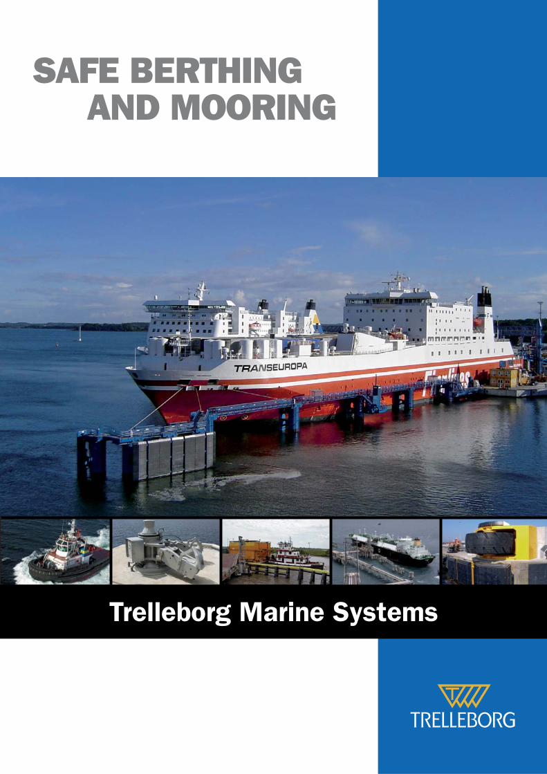
SAFE BERTHING AND MOORING
Trelleborg Marine Systems
© Trelleborg AB, 2007
M1100, version 1.1-EN
A–2
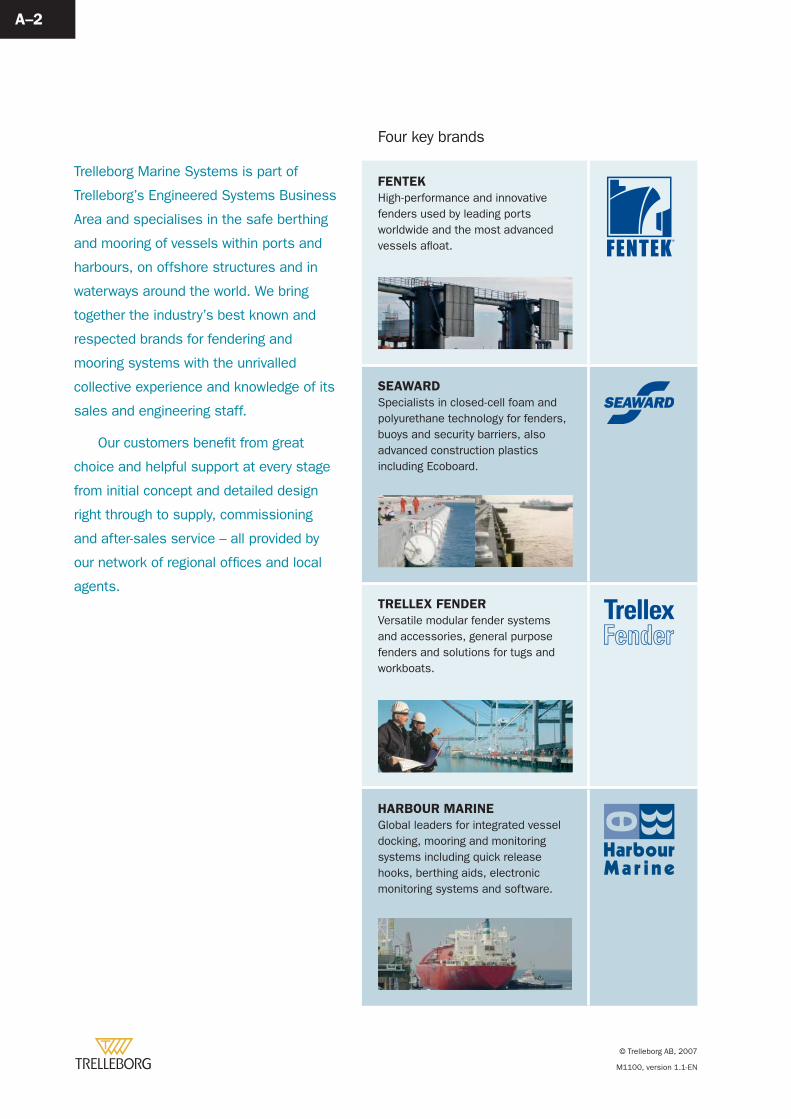
Four key brands
FENTEK
High-performance and innovative fenders used by leading ports worldwide and the most advanced vessels afl oat.
SEAWARD
Specialists in closed-cell foam and polyurethane technology for fenders, buoys and security barriers, also advanced construction plastics including Ecoboard.
TRELLEX FENDER
Versatile modular fender systems and accessories, general purpose fenders and solutions for tugs and workboats.
HARBOUR MARINE
Global leaders for integrated vessel docking, mooring and monitoring systems including quick release hooks, berthing aids, electronic monitoring systems and software.
Trelleborg Marine Systems is part of
Trelleborg’s Engineered Systems Business
Area and specialises in the safe berthing
and mooring of vessels within ports and
harbours, on offshore structures and in
waterways around the world. We bring
together the industry’s best known and
respected brands for fendering and
mooring systems with the unrivalled
collective experience and knowledge of its
sales and engineering staff.
Our customers benefi t from great
choice and helpful support at every stage
from initial concept and detailed design
right through to supply, commissioning
and after-sales service – all provided by
our network of regional offi ces and local
agents.
© Trelleborg AB, 2007
M1100, version 1.1-EN
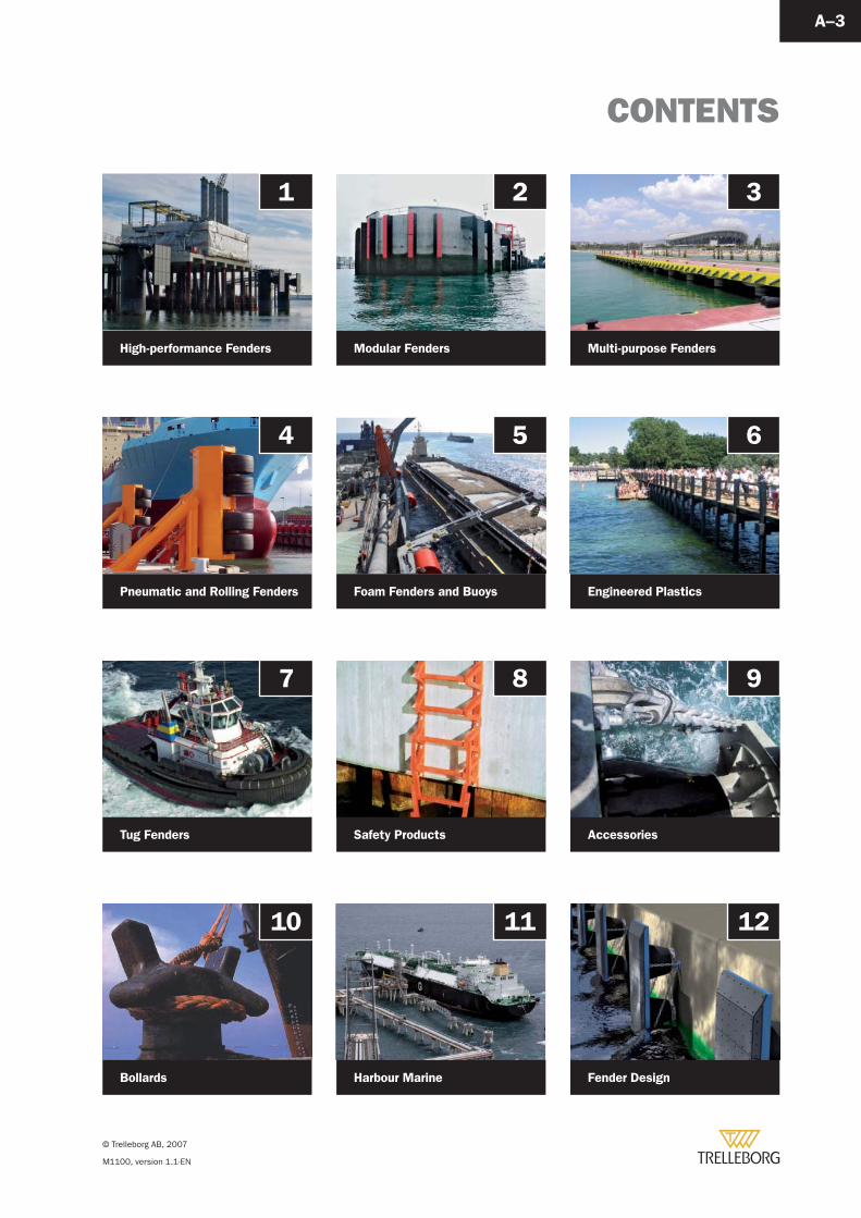
CONTENTS
A–3
1
High-performance Fenders
4
Pneumatic and Rolling Fenders
7
Tug Fenders
2
Modular Fenders
5
Foam Fenders and Buoys
8
Safety Products
3
Multi-purpose Fenders
6
Engineered Plastics
9
Accessories
10
Bollards
11
Harbour Marine
12
Fender Design

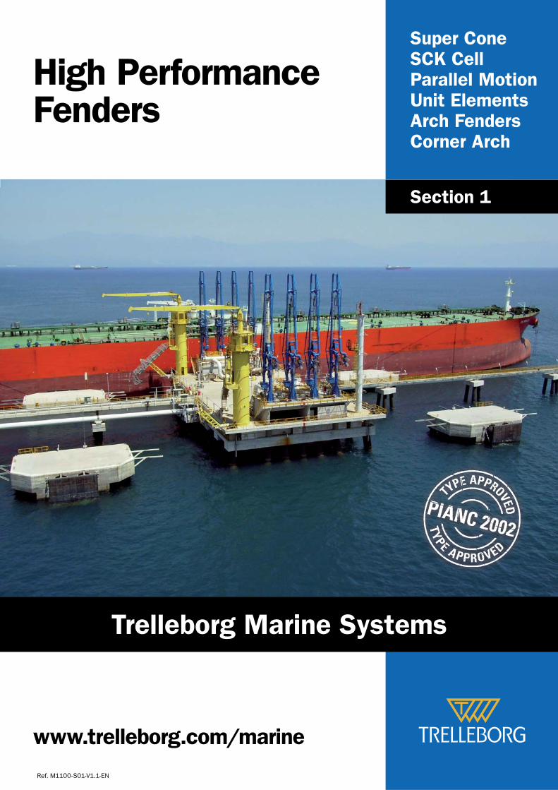
Super ConeSCK CellParallel MotionUnit ElementsArch FendersCorner Arch
High Performance Fenders
Ref. M1100-S01-V1.1-EN
Section 1
www.trelleborg.com/marine
Trelleborg Marine Systems
PIANC TYPE APPROVAL
M1100-S01-V1.1-EN.
© Trelleborg AB, 2007
1–2
PIANC is a worldwide non-political and non-profi t technical and scientifi c organization of national governments, corporations and private individuals. PIANC’s objective is to promote both inland and maritime navigation by fostering progress in the planning, design, construction, improvement, maintenance and operation of inland and maritime waterways and ports and of coastal areas for general use in industrialised and industrialising countries.
PIANC was founded in 1885 and is the oldest international association concerned with these technical aspects of navigation. It has made – and continues to make – a vital contribution to technical development in this fi eld. PIANC’s members form an active world-wide network of professionals in the fi eld of inland and maritime navigation and ports.
Trelleborg Marine Systems is a corporate member of PIANC.
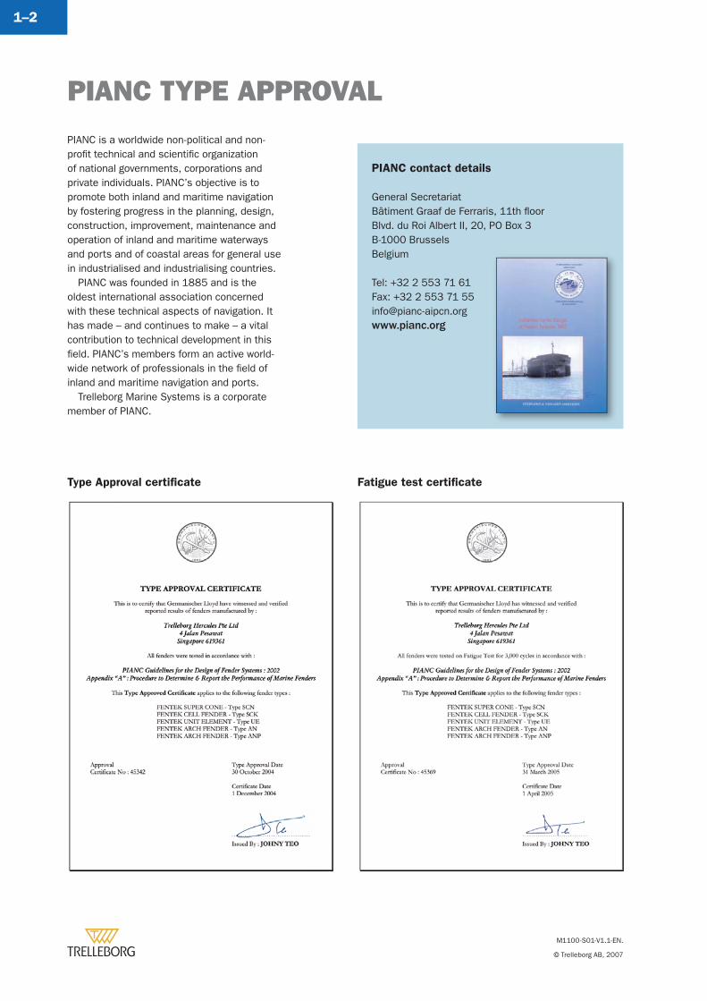
Type Approval certifi cate Fatigue test certifi cate
PIANC contact details
General SecretariatBâtiment Graaf de Ferraris, 11th fl oorBlvd. du Roi Albert II, 20, PO Box 3B-1000 BrusselsBelgium
Tel: +32 2 553 71 61Fax: +32 2 553 71 [email protected]
PIANC TYPE APPROVAL
M1100-S01-V1.1-EN.
© Trelleborg AB, 2007
1–3
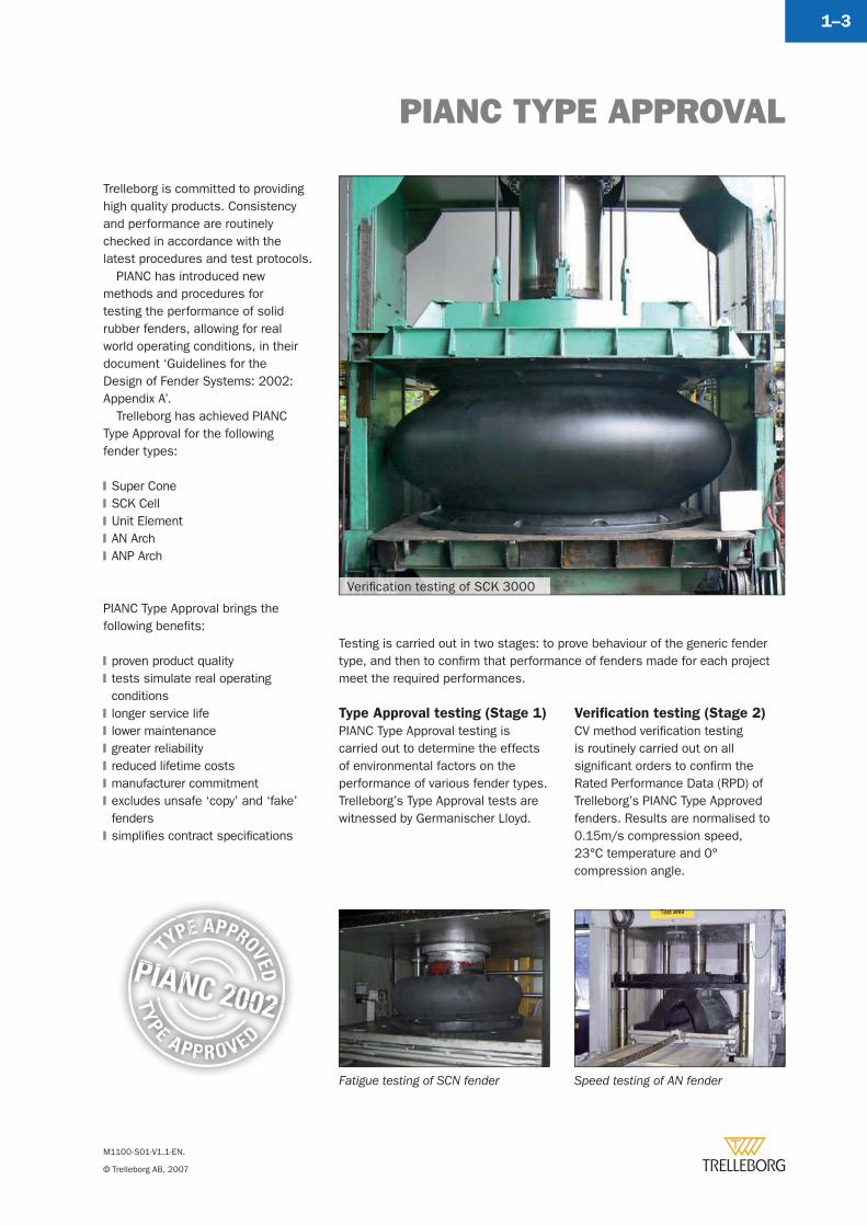
Trelleborg is committed to providing high quality products. Consistency and performance are routinely checked in accordance with the latest procedures and test protocols.
PIANC has introduced new methods and procedures for testing the performance of solid rubber fenders, allowing for real world operating conditions, in their document ‘Guidelines for the Design of Fender Systems: 2002: Appendix A’.
Trelleborg has achieved PIANC Type Approval for the following fender types:
Super ConeSCK CellUnit ElementAN ArchANP Arch
PIANC Type Approval brings the following benefi ts:
proven product qualitytests simulate real operating conditionslonger service lifelower maintenancegreater reliabilityreduced lifetime costsmanufacturer commitmentexcludes unsafe ‘copy’ and ‘fake’ fenderssimplifi es contract specifi cations
�
�
�
�
�
�
�
�
�
�
�
�
�
�
Testing is carried out in two stages: to prove behaviour of the generic fender type, and then to confi rm that performance of fenders made for each project meet the required performances.
Verifi cation testing (Stage 2)
CV method verifi cation testing is routinely carried out on all signifi cant orders to confi rm the Rated Performance Data (RPD) of Trelleborg’s PIANC Type Approved fenders. Results are normalised to 0.15m/s compression speed, 23°C temperature and 0° compression angle.
Type Approval testing (Stage 1)
PIANC Type Approval testing is carried out to determine the effects of environmental factors on the performance of various fender types. Trelleborg’s Type Approval tests are witnessed by Germanischer Lloyd.
Verifi cation testing of SCK 3000
Speed testing of AN fenderFatigue testing of SCN fender
Standard manufacturing and performance tolerances apply (see pages 12–36 to 12–39)
M1100-S01-V1.1-EN. © Trelleborg AB, 2007
1–41–4
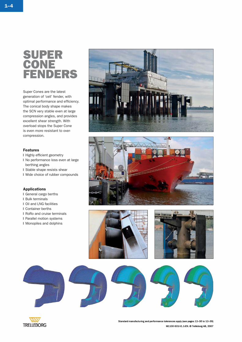
Super Cones are the latest generation of ‘cell’ fender, with optimal performance and effi ciency. The conical body shape makes the SCN very stable even at large compression angles, and provides excellent shear strength. With overload stops the Super Cone is even more resistant to over-compression.
Features
Highly effi cient geometryNo performance loss even at large berthing anglesStable shape resists shearWide choice of rubber compounds
Applications
General cargo berthsBulk terminalsOil and LNG facilitiesContainer berthsRoRo and cruise terminalsParallel motion systemsMonopiles and dolphins
�
�
�
�
�
�
�
�
�
�
�
SUPER CONEFENDERS
Standard manufacturing and performance tolerances apply (see pages 12–36 to 12–39)
M1100-S01-V1.1-EN. © Trelleborg AB, 2007
Standard manufacturing and performance tolerances apply (see pages 12–36 to 12–39)
M1100-S01-V1.1-EN. © Trelleborg AB, 2007
SUPER CONE FENDERS
Standard manufacturing and performance tolerances apply (see pages 12–36 to 12–39)
M1100-S01-V1.1-EN. © Trelleborg AB, 2007
1–5
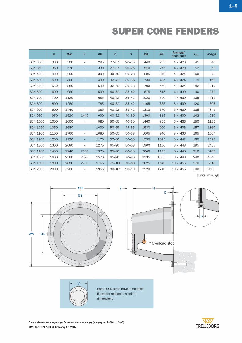
H ØW V ØU C D ØB ØS Anchors/Head bolts Zmin Weight
SCN 300 300 500 – 295 27–37 20–25 440 255 4 × M20 45 40
SCN 350 350 570 – 330 27–37 20–25 510 275 4 × M20 52 50
SCN 400 400 650 – 390 30–40 20–28 585 340 4 × M24 60 76
SCN 500 500 800 – 490 32–42 30–38 730 425 4 × M24 75 160
SCN 550 550 880 – 540 32–42 30–38 790 470 4 × M24 82 210
SCN 600 600 960 – 590 40–52 35–42 875 515 4 × M30 90 270
SCN 700 700 1120 – 685 40–52 35–42 1020 600 4 × M30 105 411
SCN 800 800 1280 – 785 40–52 35–42 1165 685 6 × M30 120 606
SCN 900 900 1440 – 885 40–52 35–42 1313 770 6 × M30 135 841
SCN 950 950 1520 1440 930 40–52 40–50 1390 815 6 × M30 142 980
SCN 1000 1000 1600 – 980 50–65 40–50 1460 855 6 × M36 150 1125
SCN 1050 1050 1680 – 1030 50–65 45–55 1530 900 6 × M36 157 1360
SCN 1100 1100 1760 – 1080 50–65 50–58 1605 940 8 × M36 165 1567
SCN 1200 1200 1920 – 1175 57–80 50–58 1750 1025 8 × M42 180 2028
SCN 1300 1300 2080 – 1275 65–90 50–58 1900 1100 8 × M48 195 2455
SCN 1400 1400 2240 2180 1370 65–90 60–70 2040 1195 8 × M48 210 3105
SCN 1600 1600 2560 2390 1570 65–90 70–80 2335 1365 8 × M48 240 4645
SCN 1800 1800 2880 2700 1765 75–100 70–80 2625 1540 10 × M56 270 6618
SCN 2000 2000 3200 – 1955 80–105 90–105 2920 1710 10 × M56 300 9560
Overload stop
C
ØW ØU
ØB Z HD
ØS
[ Units: mm, kg ]
Some SCN sizes have a modifi ed
fl ange for reduced shipping
dimensions.
V
SUPER CONE FENDERS
Standard manufacturing and performance tolerances apply (see pages 12–36 to 12–39)
M1100-S01-V1.1-EN. © Trelleborg AB, 2007
SUPER CONE FENDERS
Standard manufacturing and performance tolerances apply (see pages 12–36 to 12–39)
M1100-S01-V1.1-EN. © Trelleborg AB, 2007
SUPER CONE FENDERS
Standard manufacturing and performance tolerances apply (see pages 12–36 to 12–39)
M1100-S01-V1.1-EN. © Trelleborg AB, 2007
1–6
100
100
0 5 10 15 20 25 30 35 40 45 50 55 60 65 70 75
Rea
ctio
n (%
)
Ener
gy (%
)
Deflection (%) 72
0
20
40
60
80
120
0
20
40
60
80
120
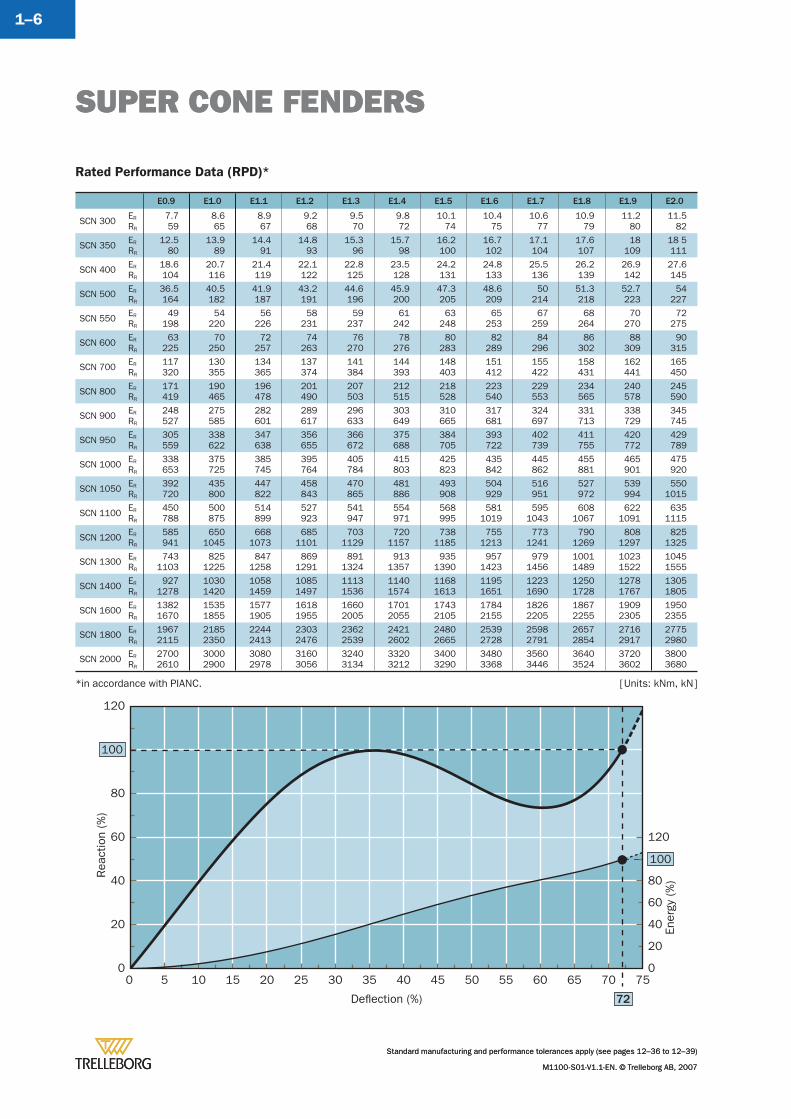
Rated Performance Data (RPD)*
E0.9 E1.0 E1.1 E1.2 E1.3 E1.4 E1.5 E1.6 E1.7 E1.8 E1.9 E2.0
SCN 300 ER
RR
7.759
8.665
8.967
9.268
9.570
9.872
10.174
10.475
10.677
10.979
11.280
11.582
SCN 350 ER
RR
12.580
13.989
14.491
14.893
15.396
15.798
16.2100
16.7102
17.1104
17.6107
18109
18 5111
SCN 400 ER
RR
18.6104
20.7116
21.4119
22.1122
22.8125
23.5128
24.2131
24.8133
25.5136
26.2139
26.9142
27.6145
SCN 500 ER
RR
36.5164
40.5182
41.9187
43.2191
44.6196
45.9200
47.3205
48.6209
50214
51.3218
52.7223
54227
SCN 550 ER
RR
49198
54220
56226
58231
59237
61242
63248
65253
67259
68264
70270
72275
SCN 600 ER
RR
63225
70250
72257
74263
76270
78276
80283
82289
84296
86302
88309
90315
SCN 700 ER
RR
117320
130355
134365
137374
141384
144393
148403
151412
155422
158431
162441
165450
SCN 800 ER
RR
171419
190465
196478
201490
207503
212515
218528
223540
229553
234565
240578
245590
SCN 900 ER
RR
248527
275585
282601
289617
296633
303649
310665
317681
324697
331713
338729
345745
SCN 950 ER
RR
305559
338622
347638
356655
366672
375688
384705
393722
402739
411755
420772
429789
SCN 1000 ER
RR
338653
375725
385745
395764
405784
415803
425823
435842
445862
455881
465901
475920
SCN 1050 ER
RR
392720
435800
447822
458843
470865
481886
493908
504929
516951
527972
539994
5501015
SCN 1100 ER
RR
450788
500875
514899
527923
541947
554971
568995
5811019
5951043
6081067
6221091
6351115
SCN 1200 ER
RR
585941
6501045
6681073
6851101
7031129
7201157
7381185
7551213
7731241
7901269
8081297
8251325
SCN 1300 ER
RR
7431103
8251225
8471258
8691291
8911324
9131357
9351390
9571423
9791456
10011489
10231522
10451555
SCN 1400 ER
RR
9271278
10301420
10581459
10851497
11131536
11401574
11681613
11951651
12231690
12501728
12781767
13051805
SCN 1600 ER
RR
13821670
15351855
15771905
16181955
16602005
17012055
17432105
17842155
18262205
18672255
19092305
19502355
SCN 1800 ER
RR
19672115
21852350
22442413
23032476
23622539
24212602
24802665
25392728
25982791
26572854
27162917
27752980
SCN 2000 ER
RR
27002610
30002900
30802978
31603056
32403134
33203212
34003290
34803368
35603446
36403524
37203602
38003680
*in accordance with PIANC.
SUPER CONE FENDERS
Standard manufacturing and performance tolerances apply (see pages 12–36 to 12–39)
M1100-S01-V1.1-EN. © Trelleborg AB, 2007
[ Units: kNm, kN ]
SUPER CONE FENDERS
Standard manufacturing and performance tolerances apply (see pages 12–36 to 12–39)
M1100-S01-V1.1-EN. © Trelleborg AB, 2007
1–7
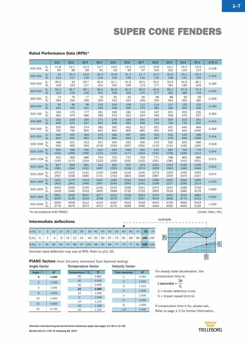
Rated Performance Data (RPD)*
E2.1 E2.2 E2.3 E2.4 E2.5 E2.6 E2.7 E2.8 E2.9 E3.0 E3.1 E/R (å)
SCN 300 ER
RR
11.884
12.186
12.489
12.791
13.093
13.395
13.597
13.8100
14.1102
14.4104
15.9114 0.138
SCN 350 ER
RR
19114
19.4117
19.9120
20.3123
20.8126
21.3129
21.7132
22.2135
22.6138
23.1141
25.4155 0.163
SCN 400 ER
RR
28.3149
29153
29.7157
30.4161
31 1165
31.8169
32.5173
33.2177
33.9181
34.6185
38.1204 0.186
SCN 500 ER
RR
55.4233
56.7239
58.1246
59.4252
60.8258
62.2264
63.5270
64.9277
66.2283
67.6289
74.4318 0.232
SCN 550 ER
RR
74283
76290
77298
79305
81313
83320
85328
86335
88343
90350
99385 0.256
SCN 600 ER
RR
93324
96332
99341
102349
105358
108366
111375
114383
117392
120400
132440 0.290
SCN 700 ER
RR
169462
173474
177486
181498
185510
189522
193534
197546
201558
205570
226627 0.364
SCN 800 ER
RR
252606
258621
265637
271652
278668
284683
291699
297714
304730
310745
341820 0.414
SCN 900 ER
RR
355765
364785
374805
383825
393845
402865
412885
421905
431925
440945
4841040 0.466
SCN 950 ER
RR
440810
452831
463852
475873
486894
497915
509936
520957
532978
543999
5981099 0.544
SCN 1000 ER
RR
488945
501969
514994
5271018
5401043
5531067
5661092
5791116
5921141
6051165
6661282 0.518
SCN 1050 ER
RR
5651042
5801069
5951096
6101123
6251150
6401177
6551204
6701231
6851258
7001285
7701414 0.544
SCN 1100 ER
RR
6521145
6691174
6861204
7031233
7201263
7371292
7541322
7711351
7881381
8051410
8861551 0.571
SCN 1200 ER
RR
8471361
8691396
8911432
9131467
9351503
9571538
9791574
10011609
10231645
10451680
11501848 0.622
SCN 1300 ER
RR
10741597
11021638
11311680
11591721
11881763
12161804
12451846
12731887
13021929
13301970
14632167 0.674
SCN 1400 ER
RR
13411853
13761901
14121949
14471997
14832045
15182093
15542141
15892189
16252237
16602285
18262514 0.725
SCN 1600 ER
RR
20032418
20562480
21092543
21622605
22152668
22682730
23212793
23742855
24272918
24802980
27283278 0.830
SCN 1800 ER
RR
28513060
29263139
30023219
30773298
31533378
32283457
33043537
33793616
34553696
35303775
38834153 0.932
SCN 2000 ER
RR
39043778
40083876
41123974
42164072
43204170
44244268
45284366
46324464
47364562
48404660
53245126 1.039
PIANC factors (from 3rd party witnessed Type Approval testing)
Intermediate defl ections
Di (%) 0 5 10 15 20 25 30 35 40 45 50 55 60 65 70 72 75
Ei (%) 0 1 4 8 15 22 31 40 50 59 67 75 82 89 96 100 106
Ri (%) 0 19 39 59 75 89 97 100 98 92 84 77 73 77 91 100 118
Angle factor
Angle (°) AF
0 1.000
3 1.039
5 1.055
8 1.029
10 1.000
15 0.856
20 0.739
Ei
Ri
Di
For steady state deceleration, the
compression time is:
d = fender defl ection (mm)
Vi = impact speed (mm/s)
If compression time t<4s, please ask.
Refer to page 1–2 for further information.
Vi
2dt (seconds) =
Vi
2dt (seconds) =
example
*in accordance with PIANC.
Temperature factor
Temperature (°C) TF50 0.882
40 0.926
30 0.969
23 1.000
10 1.056
0 1.099
-10 1.143
-20 1.186
-30 1.230
Velocity factor
Time (seconds) VF
1 1.050
2 1.020
3 1.012
4 1.005
5 1.000
6 1.000
8 1.000
≥10 1.000
Nominal rated defl ection may vary at RPD. Refer to p12–35.
SUPER CONE FENDERS
Standard manufacturing and performance tolerances apply (see pages 12–36 to 12–39)
M1100-S01-V1.1-EN. © Trelleborg AB, 2007
[ Units: kNm, kN ]
SUPER CONE FENDERS
Standard manufacturing and performance tolerances apply (see pages 12–36 to 12–39)
M1100-S01-V1.1-EN. © Trelleborg AB, 2007
1–8
WH
WV
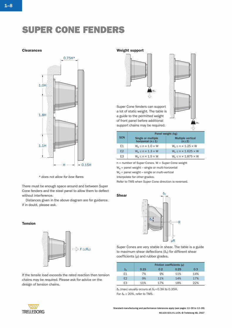
Clearances
There must be enough space around and between Super Cone fenders and the steel panel to allow them to defl ect without interference.
Distances given in the above diagram are for guidance. If in doubt, please ask.
Weight support
Tension
SCNPanel weight (kg)
Single or multiplehorizontal (n ≥ 1)
Multiple vertical(n ≥ 2)
E1 WH ≤ n × 1.0 × W WV ≤ n × 1.25 × W
E2 WH ≤ n × 1.3 × W WV ≤ n × 1.625 × W
E3 WH ≤ n × 1.5 × W WV ≤ n × 1.875 × W
If the tensile load exceeds the rated reaction then tension chains may be required. Please ask for advice on the design of tension chains.
Shear
Super Cones are very stable in shear. The table is a guide to maximum shear defl ections (äS) for different shear coeffi cients (μ) and rubber grades.
Friction coeffi cients (μ)
äS 0.15 0.2 0.25 0.3
E1 7% 9% 11% 14%
E2 9% 11% 14% 17%E3 11% 17% 18% 22%
äS (max) usually occurs at äC = 0.3H to 0.35H.
For äS ≥ 20%, refer to TMS.
1.8H
1.0H
0.15HH
0.75H*
1.1H
Super Cone fenders can support a lot of static weight. The table is a guide to the permitted weight of front panel before additional support chains may be required.
* does not allow for bow fl ares
F (≤RR)
n = number of Super Cones. W = Super Cone weight
WH = panel weight – single or multi-horizontal
WV = panel weight – single or multi-vertical
Interpolate for other grades.
Refer to TMS when Super Cone direction is reversed.
R
μR
äC
äS
SUPER CONE FENDERS
Standard manufacturing and performance tolerances apply (see pages 12–36 to 12–39)
M1100-S01-V1.1-EN. © Trelleborg AB, 2007
SUPER CONE FENDERS
Standard manufacturing and performance tolerances apply (see pages 12–36 to 12–39)
M1100-S01-V1.1-EN. © Trelleborg AB, 2007
1–9
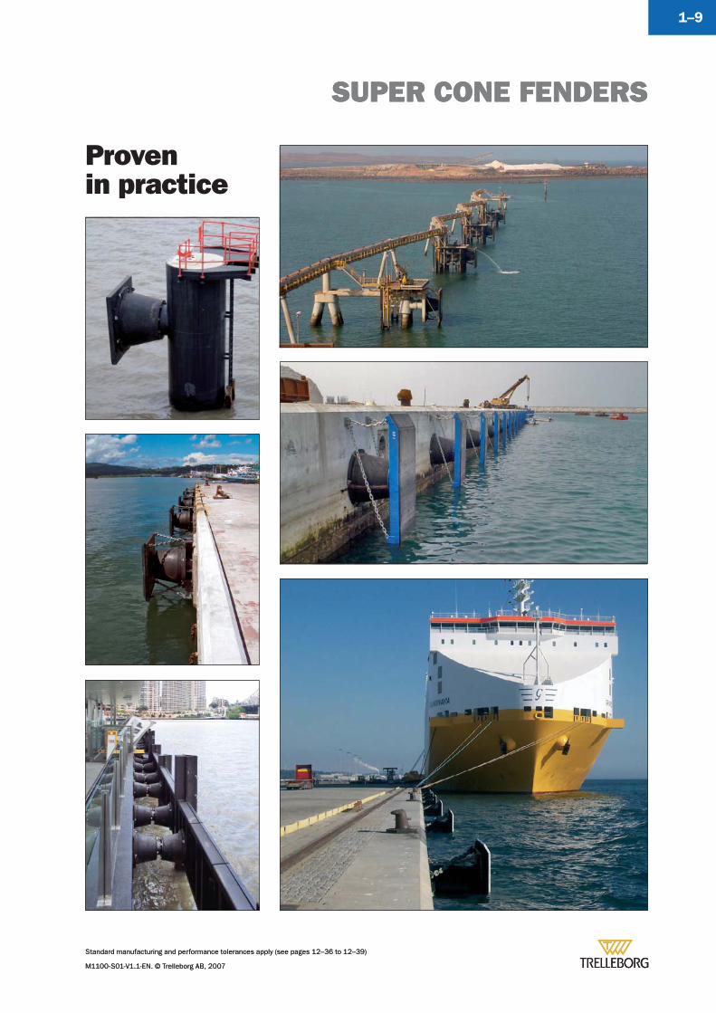
Provenin practice
SUPER CONE FENDERS
Standard manufacturing and performance tolerances apply (see pages 12–36 to 12–39)
M1100-S01-V1.1-EN. © Trelleborg AB, 2007
Standard manufacturing and performance tolerances apply (see pages 12–36 to 12–39)
M1100-S01-V1.1-EN. © Trelleborg AB, 2007
1–10
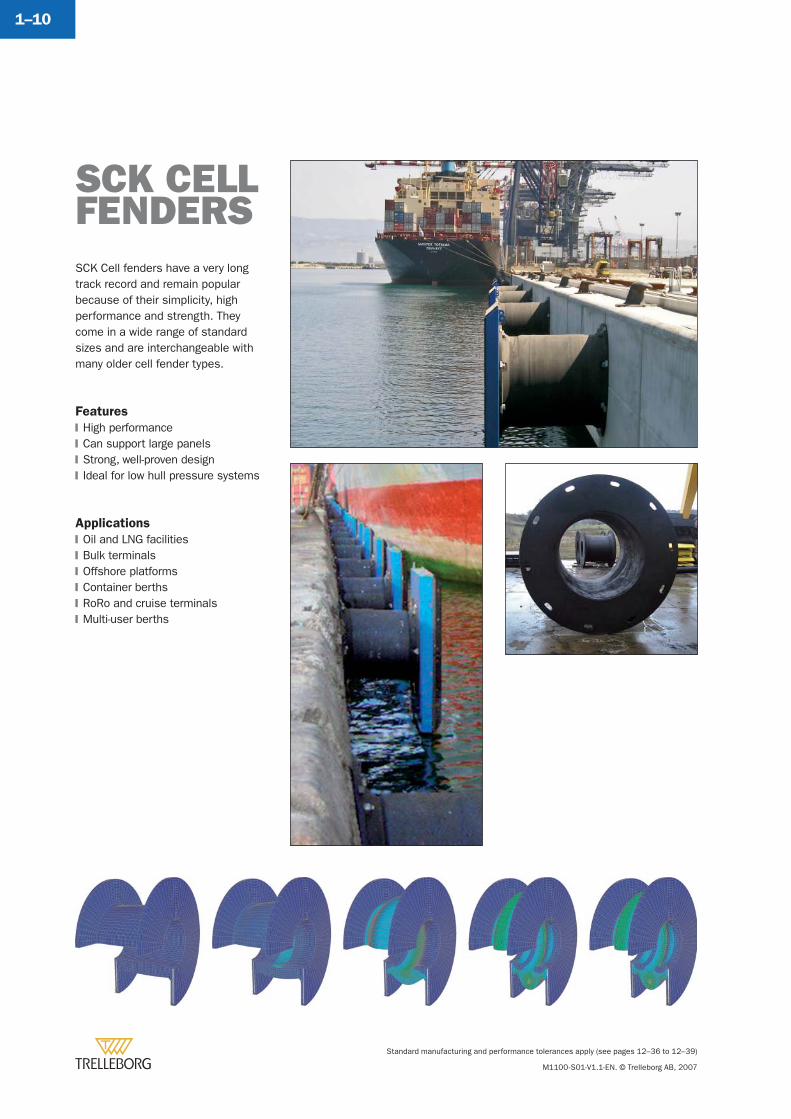
SCK Cell fenders have a very long track record and remain popular because of their simplicity, high performance and strength. They come in a wide range of standard sizes and are interchangeable with many older cell fender types.
Features
High performanceCan support large panelsStrong, well-proven designIdeal for low hull pressure systems
Applications
Oil and LNG facilitiesBulk terminalsOffshore platformsContainer berthsRoRo and cruise terminalsMulti-user berths
�
�
�
�
�
�
�
�
�
�
SCK CELLFENDERS
SCK CELL FENDERS
Standard manufacturing and performance tolerances apply (see pages 12–36 to 12–39)
M1100-S01-V1.1-EN. © Trelleborg AB, 2007
1–11
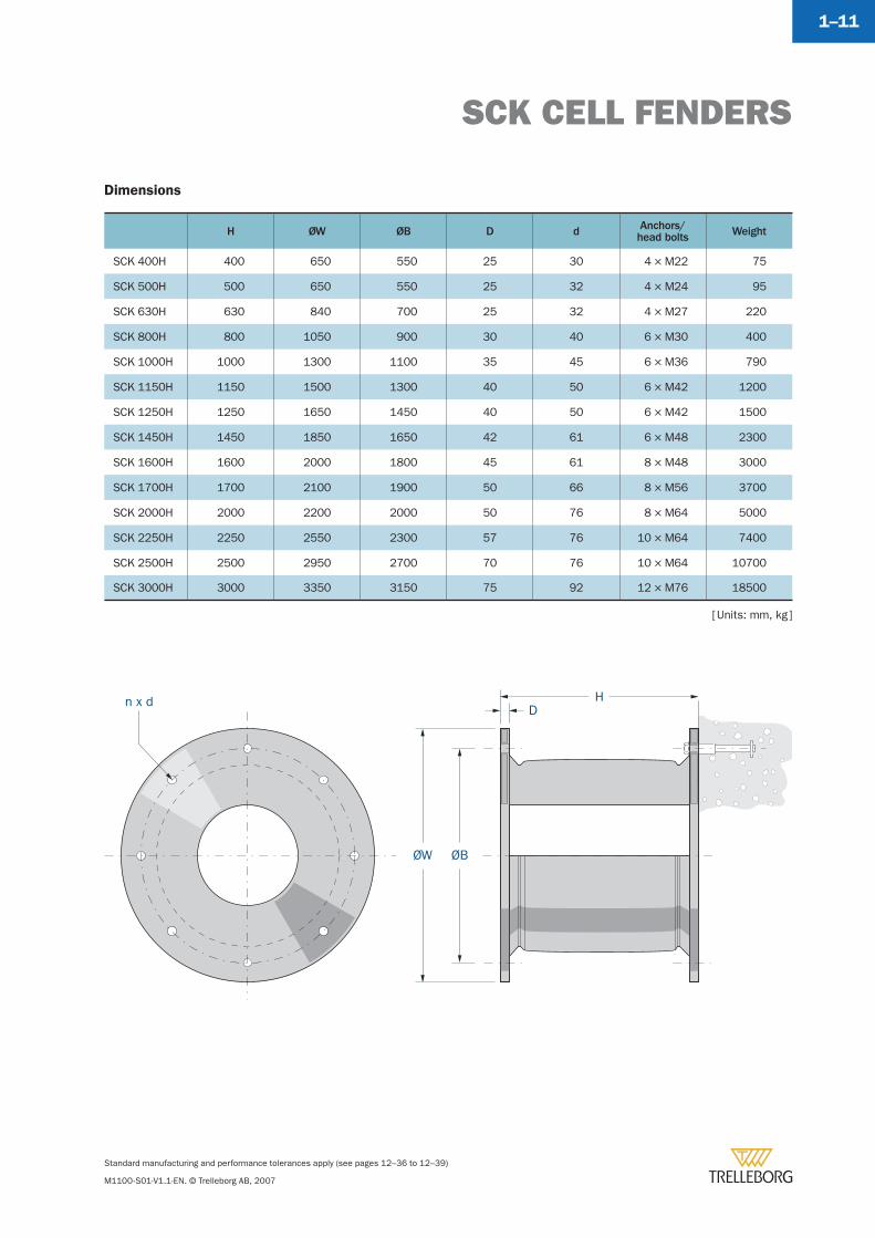
Dimensions
H ØW ØB D d Anchors/head bolts Weight
SCK 400H 400 650 550 25 30 4 × M22 75
SCK 500H 500 650 550 25 32 4 × M24 95
SCK 630H 630 840 700 25 32 4 × M27 220
SCK 800H 800 1050 900 30 40 6 × M30 400
SCK 1000H 1000 1300 1100 35 45 6 × M36 790
SCK 1150H 1150 1500 1300 40 50 6 × M42 1200
SCK 1250H 1250 1650 1450 40 50 6 × M42 1500
SCK 1450H 1450 1850 1650 42 61 6 × M48 2300
SCK 1600H 1600 2000 1800 45 61 8 × M48 3000
SCK 1700H 1700 2100 1900 50 66 8 × M56 3700
SCK 2000H 2000 2200 2000 50 76 8 × M64 5000
SCK 2250H 2250 2550 2300 57 76 10 × M64 7400
SCK 2500H 2500 2950 2700 70 76 10 × M64 10700
SCK 3000H 3000 3350 3150 75 92 12 × M76 18500
n x d HD
ØW ØB
[ Units: mm, kg ]
SCK CELL FENDERS
Standard manufacturing and performance tolerances apply (see pages 12–36 to 12–39)
M1100-S01-V1.1-EN. © Trelleborg AB, 2007
1–12
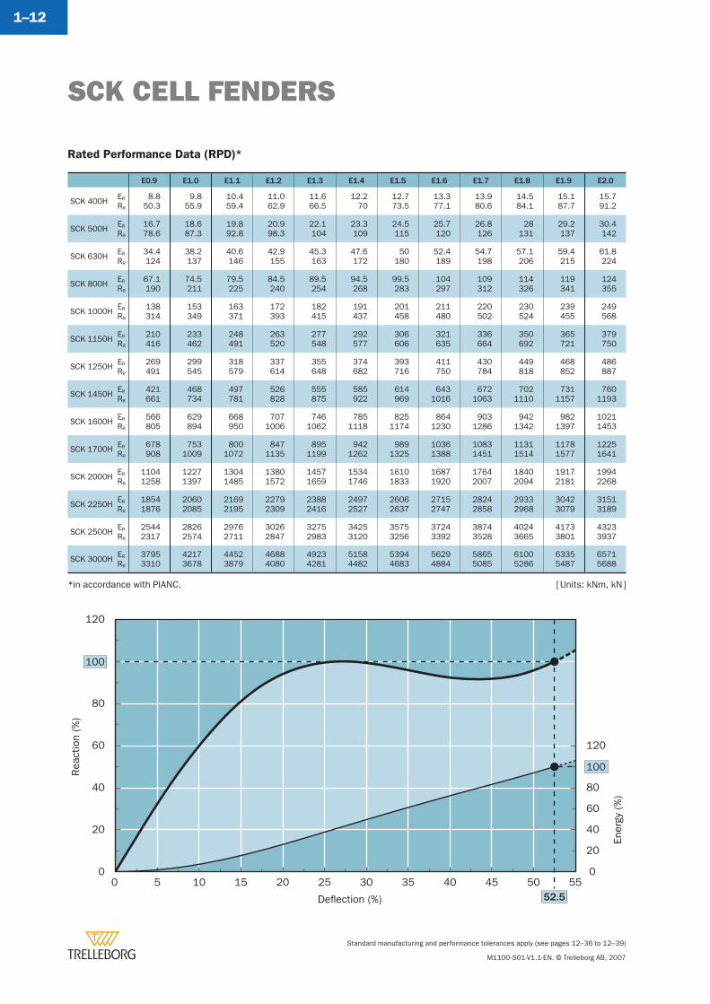
Rated Performance Data (RPD)*
E0.9 E1.0 E1.1 E1.2 E1.3 E1.4 E1.5 E1.6 E1.7 E1.8 E1.9 E2.0
SCK 400H ER
RR
8.850.3
9.855.9
10.459.4
11.062.9
11.666.5
12.270
12.773.5
13.377.1
13.980.6
14.584.1
15.187.7
15.791.2
SCK 500H ER
RR
16.778.6
18.687.3
19.892.8
20.998.3
22.1104
23.3109
24.5115
25.7120
26.8126
28131
29.2137
30.4142
SCK 630H ER
RR
34.4124
38.2137
40.6146
42.9155
45.3163
47.6172
50180
52.4189
54.7198
57.1206
59.4215
61.8224
SCK 800H ER
RR
67.1190
74.5211
79.5225
84.5240
89.5254
94.5268
99.5283
104297
109312
114326
119341
124355
SCK 1000H ER
RR
138314
153349
163371
172393
182415
191437
201458
211480
220502
230524
239455
249568
SCK 1150H ER
RR
210416
233462
248491
263520
277548
292577
306606
321635
336664
350692
365721
379750
SCK 1250H ER
RR
269491
299545
318579
337614
355648
374682
393716
411750
430784
449818
468852
486887
SCK 1450H ER
RR
421661
468734
497781
526828
555875
585922
614969
6431016
6721063
7021110
7311157
7601193
SCK 1600H ER
RR
566805
629894
668950
7071006
7461062
7851118
8251174
8641230
9031286
9421342
9821397
10211453
SCK 1700H ER
RR
678908
7531009
8001072
8471135
8951199
9421262
9891325
10361388
10831451
11311514
11781577
12251641
SCK 2000H ER
RR
11041258
12271397
13041485
13801572
14571659
15341746
16101833
16871920
17642007
18402094
19172181
19942268
SCK 2250H ER
RR
18541876
20602085
21692195
22792309
23882416
24972527
26062637
27152747
28242858
29332968
30423079
31513189
SCK 2500H ER
RR
25442317
28262574
29762711
30262847
32752983
34253120
35753256
37243392
38743528
40243665
41733801
43233937
SCK 3000H ER
RR
37953310
42173678
44523879
46884080
49234281
51584482
53944683
56294884
58655085
61005286
63355487
65715688
Rea
ctio
n (%
)
Ener
gy (%
)
Deflection (%)
100
0 5 10 15 20 25 30 35 40 45 50 5552.5
100
0
20
40
60
80
120
0
20
40
60
80
120
*in accordance with PIANC. [ Units: kNm, kN ]
SCK CELL FENDERS
Standard manufacturing and performance tolerances apply (see pages 12–36 to 12–39)
M1100-S01-V1.1-EN. © Trelleborg AB, 2007
1–13
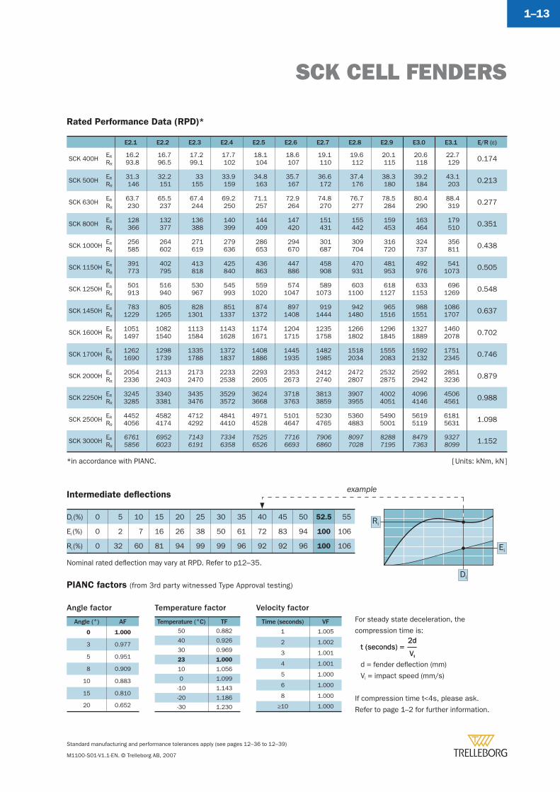
Rated Performance Data (RPD)*
E2.1 E2.2 E2.3 E2.4 E2.5 E2.6 E2.7 E2.8 E2.9 E3.0 E3.1 E/R (å)
SCK 400H ER
RR
16.293.8
16.796.5
17.299.1
17.7102
18.1104
18.6107
19.1110
19.6112
20.1115
20.6118
22.7129 0.174
SCK 500H ER
RR
31.3146
32.2151
33155
33.9159
34.8163
35.7167
36.6172
37.4176
38.3180
39.2184
43.1203 0.213
SCK 630H ER
RR
63.7230
65.5237
67.4244
69.2250
71.1257
72.9264
74.8270
76.7277
78.5284
80.4290
88.4319 0.277
SCK 800H ER
RR
128366
132377
136388
140399
144409
147420
151431
155442
159453
163464
179510 0.351
SCK 1000H ER
RR
256585
264602
271619
279636
286653
294670
301687
309704
316720
324737
356811 0.438
SCK 1150H ER
RR
391773
402795
413818
425840
436863
447886
458908
470931
481953
492976
5411073 0.505
SCK 1250H ER
RR
501913
516940
530967
545993
5591020
5741047
5891073
6031100
6181127
6331153
6961269 0.548
SCK 1450H ER
RR
7831229
8051265
8281301
8511337
8741372
8971408
9191444
9421480
9651516
9881551
10861707 0.637
SCK 1600H ER
RR
10511497
10821540
11131584
11431628
11741671
12041715
12351758
12661802
12961845
13271889
14602078 0.702
SCK 1700H ER
RR
12621690
12981739
13351788
13721837
14081886
14451935
14821985
15182034
15552083
15922132
17512345 0.746
SCK 2000H ER
RR
20542336
21132403
21732470
22332538
22932605
23532673
24122740
24722807
25322875
25922942
28513236 0.879
SCK 2250H ER
RR
32453285
33403381
34353476
35293572
36243668
37183763
38133859
39073955
40024051
40964146
45064561 0.988
SCK 2500H ER
RR
44524056
45824174
47124292
48414410
49714528
51014647
52304765
53604883
54905001
56195119
61815631 1.098
SCK 3000H ER
RR
67615856
69526023
71436191
73346358
75256526
77166693
79066860
80977028
82887195
84797363
93278099 1.152
Intermediate defl ections
Di (%) 0 5 10 15 20 25 30 35 40 45 50 52.5 55
Ei (%) 0 2 7 16 26 38 50 61 72 83 94 100 106
Ri (%) 0 32 60 81 94 99 99 96 92 92 96 100 106 Ei
Ri
Di
*in accordance with PIANC.
example
PIANC factors (from 3rd party witnessed Type Approval testing)
Angle factor
Angle (°) AF
0 1.000
3 0.977
5 0.951
8 0.909
10 0.883
15 0.810
20 0.652
For steady state deceleration, the
compression time is:
d = fender defl ection (mm)
Vi = impact speed (mm/s)
If compression time t<4s, please ask.
Refer to page 1–2 for further information.
Vi
2dt (seconds) =
Vi
2dt (seconds) =
Temperature factor
Temperature (°C) TF50 0.882
40 0.926
30 0.969
23 1.000
10 1.056
0 1.099
-10 1.143
-20 1.186
-30 1.230
Velocity factor
Time (seconds) VF
1 1.005
2 1.002
3 1.001
4 1.001
5 1.000
6 1.000
8 1.000
≥10 1.000
Nominal rated defl ection may vary at RPD. Refer to p12–35.
[ Units: kNm, kN ]
SCK CELL FENDERS
Standard manufacturing and performance tolerances apply (see pages 12–36 to 12–39)
M1100-S01-V1.1-EN. © Trelleborg AB, 2007
1–14
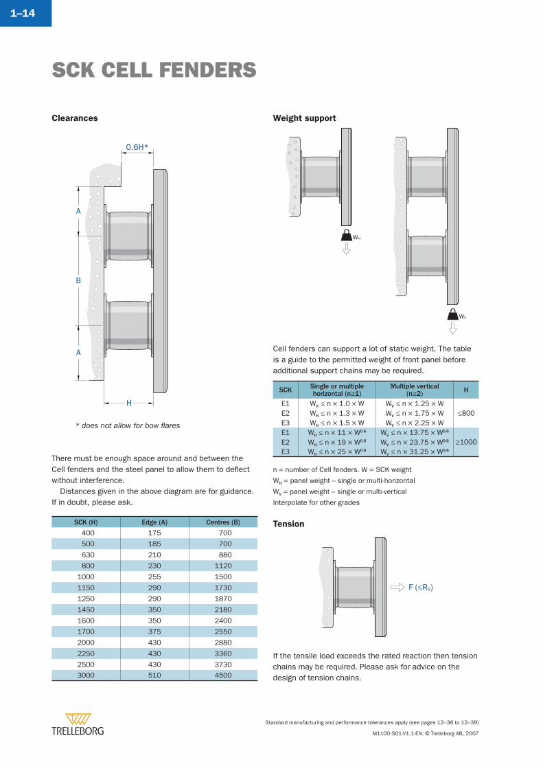
Clearances
There must be enough space around and between the Cell fenders and the steel panel to allow them to defl ect without interference.
Distances given in the above diagram are for guidance. If in doubt, please ask.
SCK (H) Edge (A) Centres (B)
400 175 700
500 185 700
630 210 880
800 230 1120
1000 255 1500
1150 290 1730
1250 290 1870
1450 350 2180
1600 350 2400
1700 375 2550
2000 430 2880
2250 430 3360
2500 430 3730
3000 510 4500
Weight support
Tension
H
0.6H*
B
A
A
SCK Single or multiplehorizontal (n≥1)
Multiple vertical(n≥2) H
E1 WH ≤ n × 1.0 × W WV ≤ n × 1.25 × W≤800E2 WH ≤ n × 1.3 × W WV ≤ n × 1.75 × W
E3 WH ≤ n × 1.5 × W WV ≤ n × 2.25 × WE1 WH ≤ n × 11 × W0.6 WV ≤ n × 13.75 × W0.6
≥1000E2 WH ≤ n × 19 × W0.6 WV ≤ n × 23.75 × W0.6
E3 WH ≤ n × 25 × W0.6 WV ≤ n × 31.25 × W0.6
If the tensile load exceeds the rated reaction then tension chains may be required. Please ask for advice on the design of tension chains.
* does not allow for bow fl ares
WH
WV
F (≤RR)
n = number of Cell fenders. W = SCK weight
WH = panel weight – single or multi-horizontal
WV = panel weight – single or multi-vertical
Interpolate for other grades
Cell fenders can support a lot of static weight. The table is a guide to the permitted weight of front panel before additional support chains may be required.
SCK CELL FENDERS
Standard manufacturing and performance tolerances apply (see pages 12–36 to 12–39)
M1100-S01-V1.1-EN. © Trelleborg AB, 2007
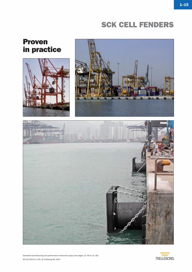
1–15
Provenin practice
Standard manufacturing and performance tolerances apply (see pages 12–36 to 12–39)
M1100-S01-V1.1-EN. © Trelleborg AB, 2007
1–16
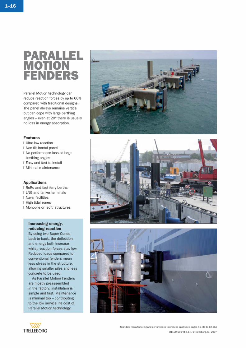
Parallel Motion technology can reduce reaction forces by up to 60% compared with traditional designs. The panel always remains vertical but can cope with large berthing angles – even at 20° there is usually no loss in energy absorption.
Features
Ultra-low reactionNon-tilt frontal panelNo performance loss at large berthing anglesEasy and fast to installMinimal maintenance
Applications
RoRo and fast ferry berthsLNG and tanker terminalsNaval facilitiesHigh tidal zonesMonopile or ‘soft’ structures
�
�
�
�
�
�
�
�
�
�
PARALLELMOTION FENDERS
Increasing energy,
reducing reaction
By using two Super Cones back-to-back, the defl ection and energy both increase whilst reaction forces stay low. Reduced loads compared to conventional fenders mean less stress in the structure, allowing smaller piles and less concrete to be used.
As Parallel Motion Fenders are mostly preassembled in the factory, installation is simple and fast. Maintenance is minimal too – contributing to the low service life cost of Parallel Motion technology.
PARALLEL MOTION FENDERS
Standard manufacturing and performance tolerances apply (see pages 12–36 to 12–39)
M1100-S01-V1.1-EN. © Trelleborg AB, 2007
1–17
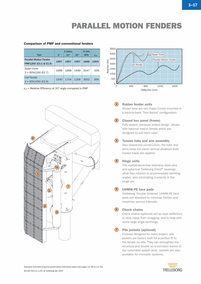
TypeE (kNm) R (kN)
å200° 10° 20° RPD
Parallel Motion Fender
PMF1200 (E3.1 & E1.9)1957 1957 1957 1848 100%
Super Cone
2 × SCN1200 (E2.7)1958 1958 1449 3147 43%
Cell Fender
2 × SCK1450 (E2.9)1930 1704 1258 3032 39%
Comparison of PMF and conventional fenders
Rubber fender units
Shown here are two Super Cones mounted in a back-to-back ‘Twin-Series’ confi guration.
Closed box panel (frame)
Fully sealed, pressure tested design. Shown with optional lead-in bevels which are designed to suit each case.
Torsion tube and arm assembly
Also closed-box construction, the tube and arms keep the panel vertical whatever level impact loads are applied.
Hinge units
The maintenance-free stainless steel pins and spherical Trelleborg Orkot® bearings allow free rotation to accommodate berthing angles, also eliminating moments in the hinge pin.
UHMW-PE face pads
Trelleborg ‘Double Sintered’ UHMW-PE face pads are standard to minimise friction and maximise service intervals.
Check chains
Check chains (optional) act as rope defl ectors to stop ropes from snagging, and to help with some large angle berthings.
Pile jackets (optional)
Purpose designed for every project, pile jackets are factory built for a perfect fi t to the fender on-site. They can strengthen the structure and double as a corrosion barrier in the vulnerable splash zone. Jackets are also available for monopile systems.
1
2
3
4
5
6
7
Super Cone
Parallel Motion Fender
Cell Fender
Rea
ctio
n (k
N)
Deflection (mm)
00
500
1000
1500
2000
2500
3000
3500
400 800 1200 1600ε20 = Relative Effi ciency at 20° angle compared to PMF
5
6
3
1
4
7
2
PARALLEL MOTION FENDERS
Standard manufacturing and performance tolerances apply (see pages 12–36 to 12–39)
M1100-S01-V1.1-EN. © Trelleborg AB, 2007
1–18
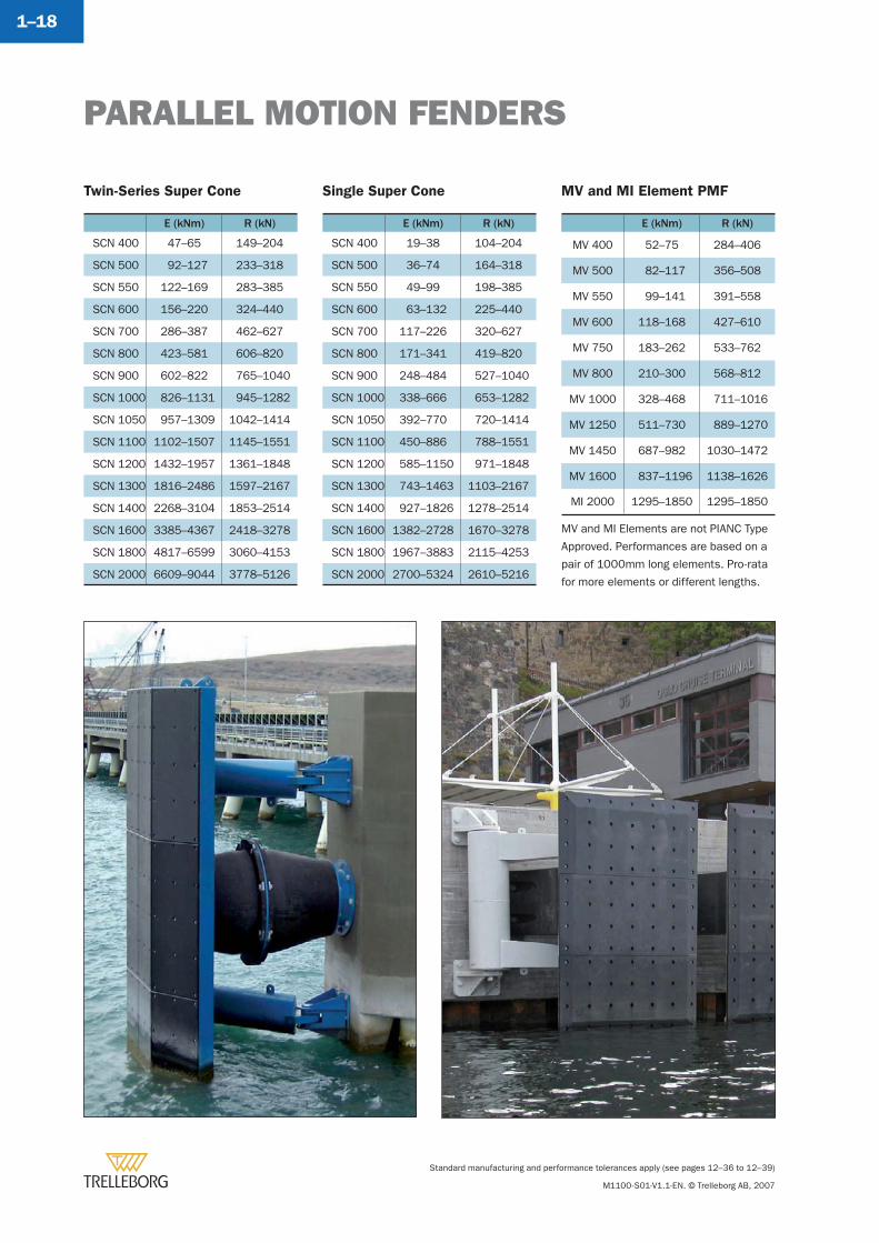
Twin-Series Super Cone
E (kNm) R (kN)
SCN 400 47–65 149–204
SCN 500 92–127 233–318
SCN 550 122–169 283–385
SCN 600 156–220 324–440
SCN 700 286–387 462–627
SCN 800 423–581 606–820
SCN 900 602–822 765–1040
SCN 1000 826–1131 945–1282
SCN 1050 957–1309 1042–1414
SCN 1100 1102–1507 1145–1551
SCN 1200 1432–1957 1361–1848
SCN 1300 1816–2486 1597–2167
SCN 1400 2268–3104 1853–2514
SCN 1600 3385–4367 2418–3278
SCN 1800 4817–6599 3060–4153
SCN 2000 6609–9044 3778–5126
Single Super Cone
E (kNm) R (kN)
SCN 400 19–38 104–204
SCN 500 36–74 164–318
SCN 550 49–99 198–385
SCN 600 63–132 225–440
SCN 700 117–226 320–627
SCN 800 171–341 419–820
SCN 900 248–484 527–1040
SCN 1000 338–666 653–1282
SCN 1050 392–770 720–1414
SCN 1100 450–886 788–1551
SCN 1200 585–1150 971–1848
SCN 1300 743–1463 1103–2167
SCN 1400 927–1826 1278–2514
SCN 1600 1382–2728 1670–3278
SCN 1800 1967–3883 2115–4253
SCN 2000 2700–5324 2610–5216
MV and MI Element PMF
E (kNm) R (kN)
MV 400 52–75 284–406
MV 500 82–117 356–508
MV 550 99–141 391–558
MV 600 118–168 427–610
MV 750 183–262 533–762
MV 800 210–300 568–812
MV 1000 328–468 711–1016
MV 1250 511–730 889–1270
MV 1450 687–982 1030–1472
MV 1600 837–1196 1138–1626
MI 2000 1295–1850 1295–1850
MV and MI Elements are not PIANC Type
Approved. Performances are based on a
pair of 1000mm long elements. Pro-rata
for more elements or different lengths.
PARALLEL MOTION FENDERS
Standard manufacturing and performance tolerances apply (see pages 12–36 to 12–39)
M1100-S01-V1.1-EN. © Trelleborg AB, 2007
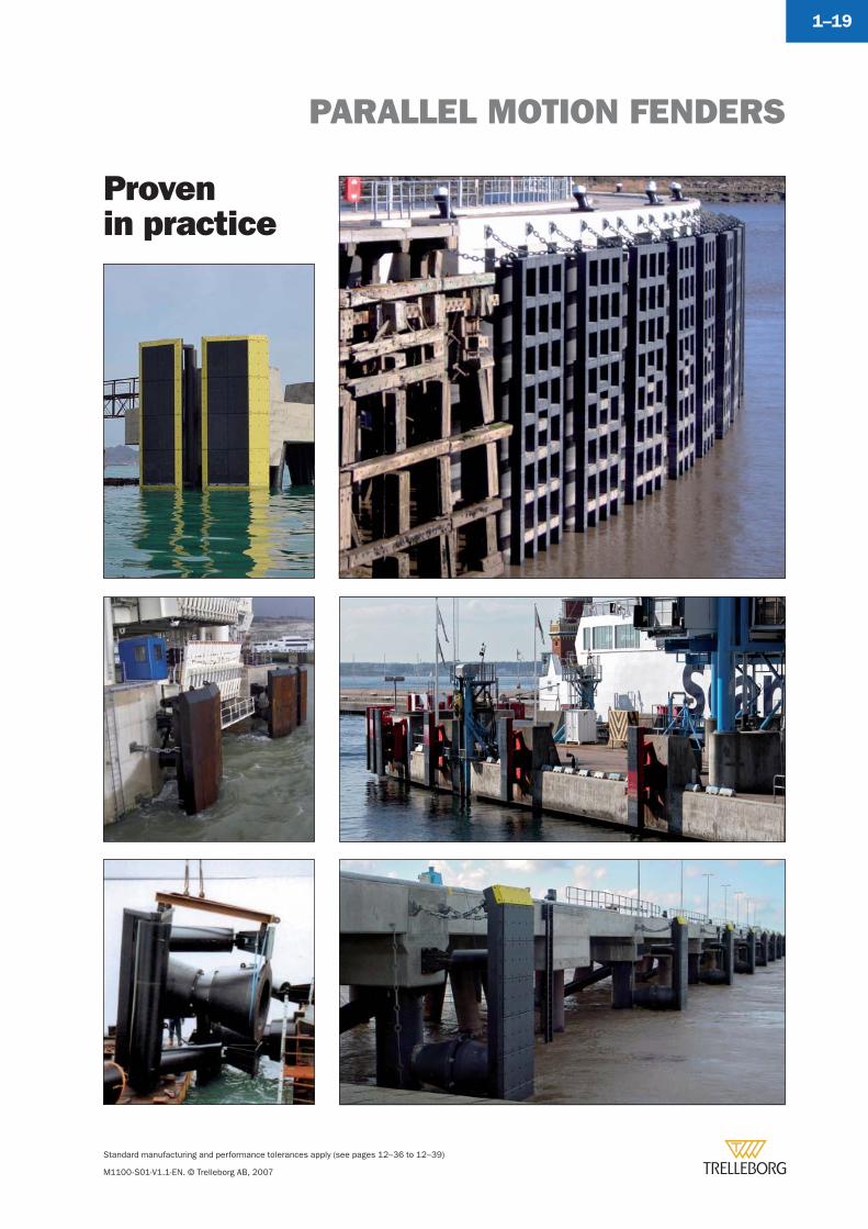
1–19
Typical footprint
Provenin practice
Standard manufacturing and performance tolerances apply (see pages 12–36 to 12–39)
M1100-S01-V1.1-EN. © Trelleborg AB, 2007
1–20
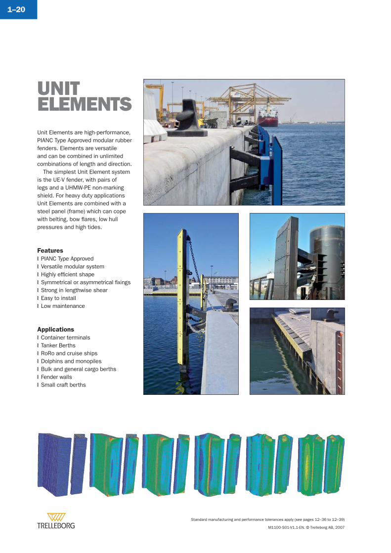
Unit Elements are high-performance, PIANC Type Approved modular rubber fenders. Elements are versatile and can be combined in unlimited combinations of length and direction.
The simplest Unit Element system is the UE-V fender, with pairs of legs and a UHMW-PE non-marking shield. For heavy duty applications Unit Elements are combined with a steel panel (frame) which can cope with belting, bow fl ares, low hull pressures and high tides.
Features
PIANC Type ApprovedVersatile modular systemHighly effi cient shapeSymmetrical or asymmetrical fi xingsStrong in lengthwise shearEasy to installLow maintenance
Applications
Container terminalsTanker BerthsRoRo and cruise shipsDolphins and monopilesBulk and general cargo berthsFender wallsSmall craft berths
�
�
�
�
�
�
�
�
�
�
�
�
�
�
UNIT ELEMENTS
UNIT ELEMENTS
Standard manufacturing and performance tolerances apply (see pages 12–36 to 12–39)
M1100-S01-V1.1-EN. © Trelleborg AB, 2007
1–21
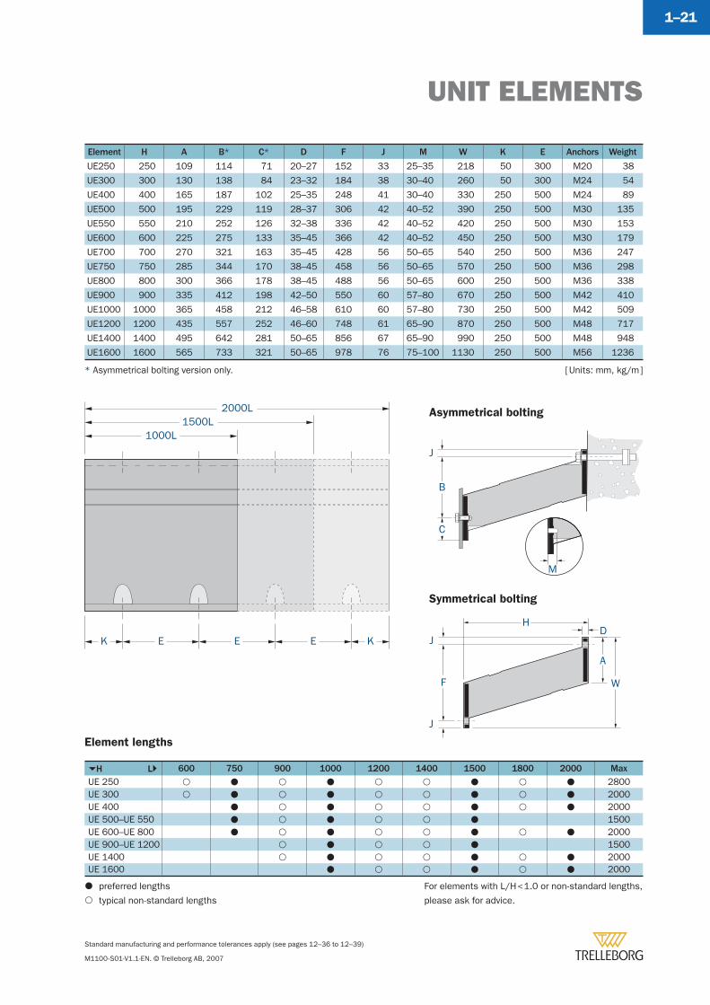
H L 600 750 900 1000 1200 1400 1500 1800 2000 MaxUE 250 2800UE 300 2000UE 400 2000UE 500–UE 550 1500UE 600–UE 800 2000UE 900–UE 1200 1500UE 1400 2000UE 1600 2000
Asymmetrical bolting
Symmetrical bolting
[ Units: mm, kg/m ]
K
1000L1500L
2000L
E E E K
M
C
J
B
HD
J
F
J
A
W
preferred lengths
typical non-standard lengths
Element lengths
Element H A B* C* D F J M W K E Anchors Weight
UE250 250 109 114 71 20–27 152 33 25–35 218 50 300 M20 38
UE300 300 130 138 84 23–32 184 38 30–40 260 50 300 M24 54
UE400 400 165 187 102 25–35 248 41 30–40 330 250 500 M24 89
UE500 500 195 229 119 28–37 306 42 40–52 390 250 500 M30 135
UE550 550 210 252 126 32–38 336 42 40–52 420 250 500 M30 153
UE600 600 225 275 133 35–45 366 42 40–52 450 250 500 M30 179
UE700 700 270 321 163 35–45 428 56 50–65 540 250 500 M36 247
UE750 750 285 344 170 38–45 458 56 50–65 570 250 500 M36 298
UE800 800 300 366 178 38–45 488 56 50–65 600 250 500 M36 338
UE900 900 335 412 198 42–50 550 60 57–80 670 250 500 M42 410
UE1000 1000 365 458 212 46–58 610 60 57–80 730 250 500 M42 509
UE1200 1200 435 557 252 46–60 748 61 65–90 870 250 500 M48 717
UE1400 1400 495 642 281 50–65 856 67 65–90 990 250 500 M48 948
UE1600 1600 565 733 321 50–65 978 76 75–100 1130 250 500 M56 1236
For elements with L/H < 1.0 or non-standard lengths,
please ask for advice.
* Asymmetrical bolting version only.
UNIT ELEMENTS
Standard manufacturing and performance tolerances apply (see pages 12–36 to 12–39)
M1100-S01-V1.1-EN. © Trelleborg AB, 2007
1–22
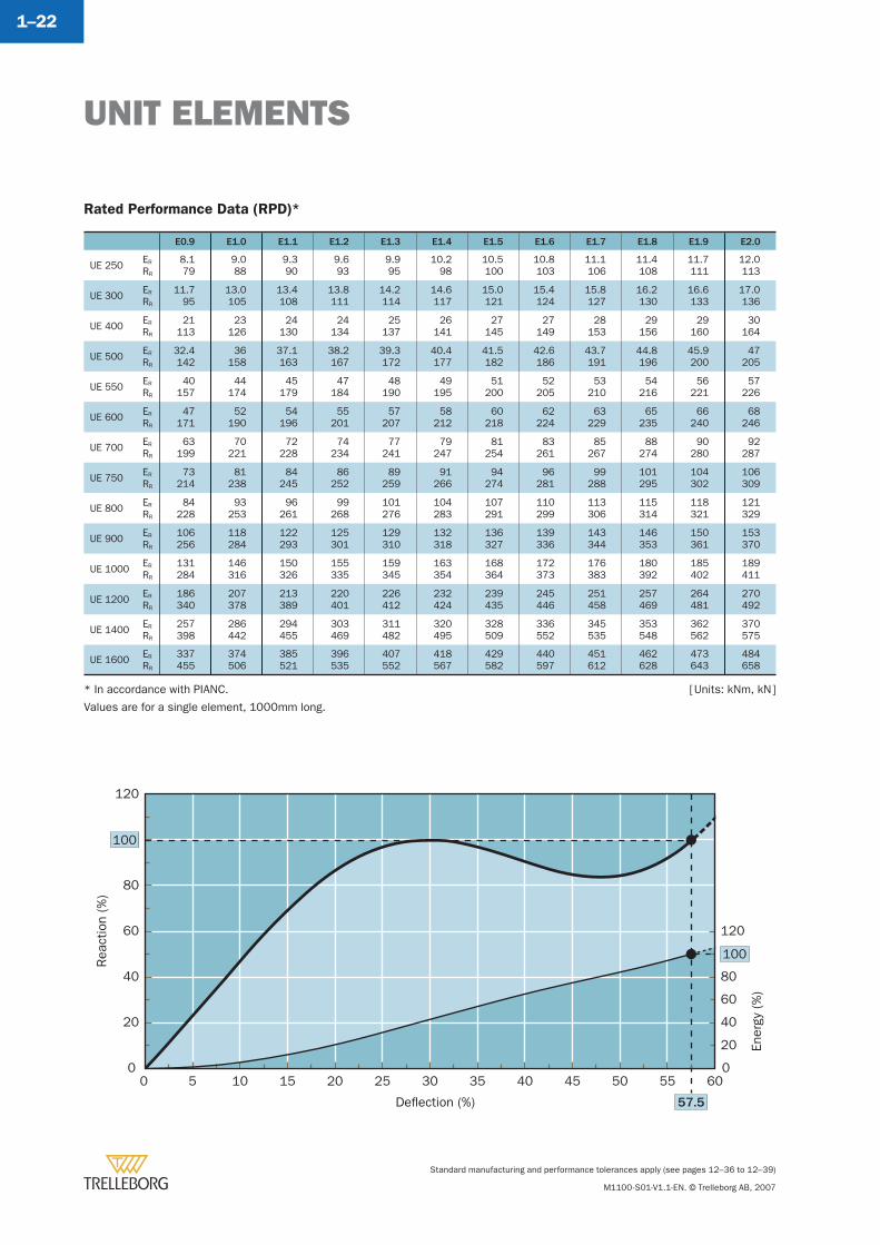
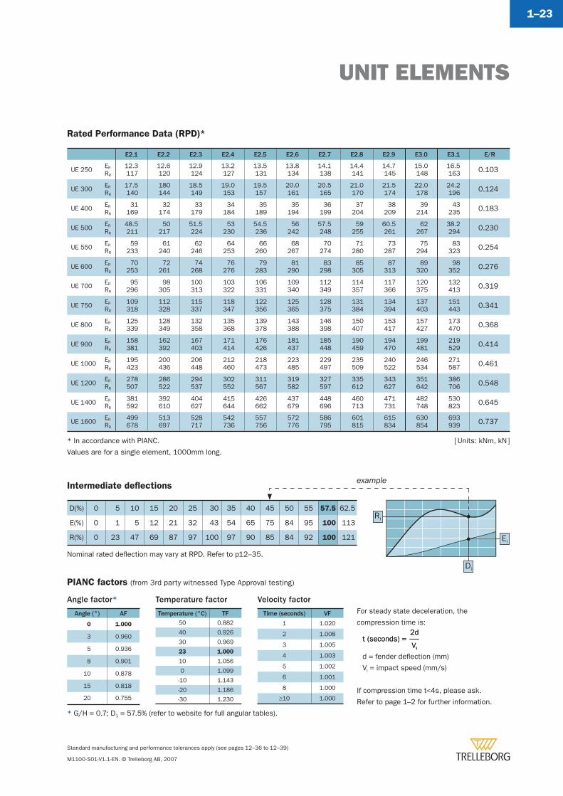
Rated Performance Data (RPD)*
E0.9 E1.0 E1.1 E1.2 E1.3 E1.4 E1.5 E1.6 E1.7 E1.8 E1.9 E2.0
UE 250 ER
RR
8.179
9.088
9.390
9.693
9.995
10.298
10.5100
10.8103
11.1106
11.4108
11.7111
12.0113
UE 300 ER
RR
11.795
13.0105
13.4108
13.8111
14.2114
14.6117
15.0121
15.4124
15.8127
16.2130
16.6133
17.0136
UE 400 ER
RR
21113
23126
24130
24134
25137
26141
27145
27149
28153
29156
29160
30164
UE 500 ER
RR
32.4142
36158
37.1163
38.2167
39.3172
40.4177
41.5182
42.6186
43.7191
44.8196
45.9200
47205
UE 550 ER
RR
40157
44174
45179
47184
48190
49195
51200
52205
53210
54216
56221
57226
UE 600 ER
RR
47171
52190
54196
55201
57207
58212
60218
62224
63229
65235
66240
68246
UE 700 ER
RR
63199
70221
72228
74234
77241
79247
81254
83261
85267
88274
90280
92287
UE 750 ER
RR
73214
81238
84245
86252
89259
91266
94274
96281
99288
101295
104302
106309
UE 800 ER
RR
84228
93253
96261
99268
101276
104283
107291
110299
113306
115314
118321
121329
UE 900 ER
RR
106256
118284
122293
125301
129310
132318
136327
139336
143344
146353
150361
153370
UE 1000 ER
RR
131284
146316
150326
155335
159345
163354
168364
172373
176383
180392
185402
189411
UE 1200 ER
RR
186340
207378
213389
220401
226412
232424
239435
245446
251458
257469
264481
270492
UE 1400 ER
RR
257398
286442
294455
303469
311482
320495
328509
336552
345535
353548
362562
370575
UE 1600 ER
RR
337455
374506
385521
396535
407552
418567
429582
440597
451612
462628
473643
484658
Rea
ctio
n (%
)
Ener
gy (%
)
Deflection (%)
0
20
40
60
80
120
0 5 10 15 20 25 30 35 40 45 50 55 60
57.5
0
40
20
60
80
120
100
100
* In accordance with PIANC.
Values are for a single element, 1000mm long.
[ Units: kNm, kN ]
UNIT ELEMENTS
Standard manufacturing and performance tolerances apply (see pages 12–36 to 12–39)
M1100-S01-V1.1-EN. © Trelleborg AB, 2007
1–23
Intermediate defl ections
D(%) 0 5 10 15 20 25 30 35 40 45 50 55 57.5 62.5
E(%) 0 1 5 12 21 32 43 54 65 75 84 95 100 113
R(%) 0 23 47 69 87 97 100 97 90 85 84 92 100 121
Rated Performance Data (RPD)*
E2.1 E2.2 E2.3 E2.4 E2.5 E2.6 E2.7 E2.8 E2.9 E3.0 E3.1 E/R
UE 250 ER
RR
12.3117
12.6120
12.9124
13.2127
13.5131
13.8134
14.1138
14.4141
14.7145
15.0148
16.5163 0.103
UE 300 ER
RR
17.5140
180144
18.5149
19.0153
19.5157
20.0161
20.5165
21.0170
21.5174
22.0178
24.2196 0.124
UE 400 ER
RR
31169
32174
33179
34184
35189
35194
36199
37204
38209
39214
43235 0.183
UE 500 ER
RR
48.5211
50217
51.5224
53230
54.5236
56242
57.5248
59255
60.5261
62267
38.2294 0.230
UE 550 ER
RR
59233
61240
62246
64253
66260
68267
70274
71280
73287
75294
83323 0.254
UE 600 ER
RR
70253
72261
74268
76276
79283
81290
83298
85305
87313
89320
98352 0.276
UE 700 ER
RR
95296
98305
100313
103322
106331
109340
112349
114357
117366
120375
132413 0.319
UE 750 ER
RR
109318
112328
115337
118347
122356
125365
128375
131384
134394
137403
151443 0.341
UE 800 ER
RR
125339
128349
132358
135368
139378
143388
146398
150407
153417
157427
173470 0.368
UE 900 ER
RR
158381
162392
167403
171414
176426
181437
185448
190459
194470
199481
219529 0.414
UE 1000 ER
RR
195423
200436
206448
212460
218473
223485
229497
235509
240522
246534
271587 0.461
UE 1200 ER
RR
278507
286522
294537
302552
311567
319582
327597
335612
343627
351642
386706 0.548
UE 1400 ER
RR
381592
392610
404627
415644
426662
437679
448696
460713
471731
482748
530823 0.645
UE 1600 ER
RR
499678
513697
528717
542736
557756
572776
586795
601815
615834
630854
693939 0.737
For steady state deceleration, the
compression time is:
d = fender defl ection (mm)
Vi = impact speed (mm/s)
If compression time t<4s, please ask.
Refer to page 1–2 for further information.
Vi
2dt (seconds) =
Vi
2dt (seconds) =
Temperature factor
Temperature (°C) TF50 0.882
40 0.926
30 0.969
23 1.000
10 1.056
0 1.099
-10 1.143
-20 1.186
-30 1.230
Velocity factor
Time (seconds) VF
1 1.020
2 1.008
3 1.005
4 1.003
5 1.002
6 1.001
8 1.000
≥10 1.000
PIANC factors (from 3rd party witnessed Type Approval testing)
Angle factor*
Angle (°) AF
0 1.000
3 0.960
5 0.936
8 0.901
10 0.878
15 0.818
20 0.755
example
Ei
Ri
Di
* In accordance with PIANC.
Values are for a single element, 1000mm long.
[ Units: kNm, kN ]
* G/H = 0.7; D1 = 57.5% (refer to website for full angular tables).
Nominal rated defl ection may vary at RPD. Refer to p12–35.
UE SYSTEMS
Standard manufacturing and performance tolerances apply (see pages 12–36 to 12–39)
M1100-S01-V1.1-EN. © Trelleborg AB, 2007
1–24
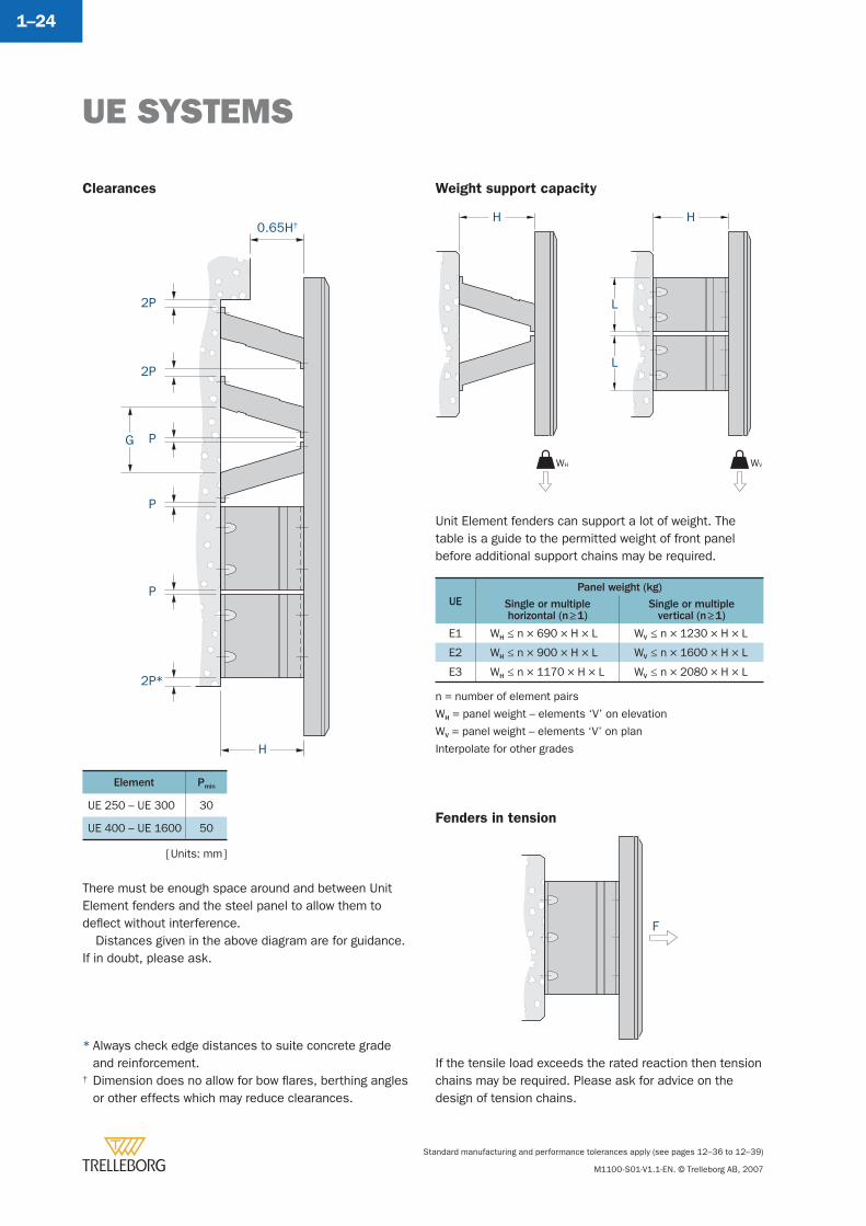
Clearances
There must be enough space around and between Unit Element fenders and the steel panel to allow them to defl ect without interference.
Distances given in the above diagram are for guidance. If in doubt, please ask.
Weight support capacity
Fenders in tension
Unit Element fenders can support a lot of weight. The table is a guide to the permitted weight of front panel before additional support chains may be required.
If the tensile load exceeds the rated reaction then tension chains may be required. Please ask for advice on the design of tension chains.
H
L
WV
L
WH
H0.65H†
H
2P*
P
P
P
2P
2P
G
F
UEPanel weight (kg)
Single or multiplehorizontal (n ≥ 1)
Single or multiplevertical (n ≥ 1)
E1 WH ≤ n × 690 × H × L WV ≤ n × 1230 × H × L
E2 WH ≤ n × 900 × H × L WV ≤ n × 1600 × H × L
E3 WH ≤ n × 1170 × H × L WV ≤ n × 2080 × H × L
n = number of element pairs
WH = panel weight – elements ‘V’ on elevation
WV = panel weight – elements ‘V’ on plan
Interpolate for other grades
Element Pmin
UE 250 – UE 300 30
UE 400 – UE 1600 50
[ Units: mm ]
* Always check edge distances to suite concrete grade and reinforcement.
† Dimension does no allow for bow fl ares, berthing angles or other effects which may reduce clearances.
UE SYSTEMS
Standard manufacturing and performance tolerances apply (see pages 12–36 to 12–39)
M1100-S01-V1.1-EN. © Trelleborg AB, 2007
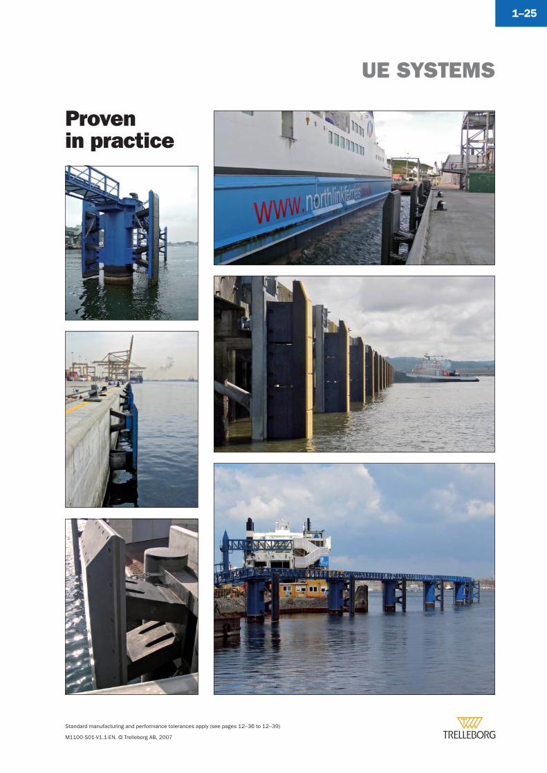
1–25
Provenin practice
Standard manufacturing and performance tolerances apply (see pages 12–36 to 12–39)
M1100-S01-V1.1-EN. © Trelleborg AB, 2007
1–26
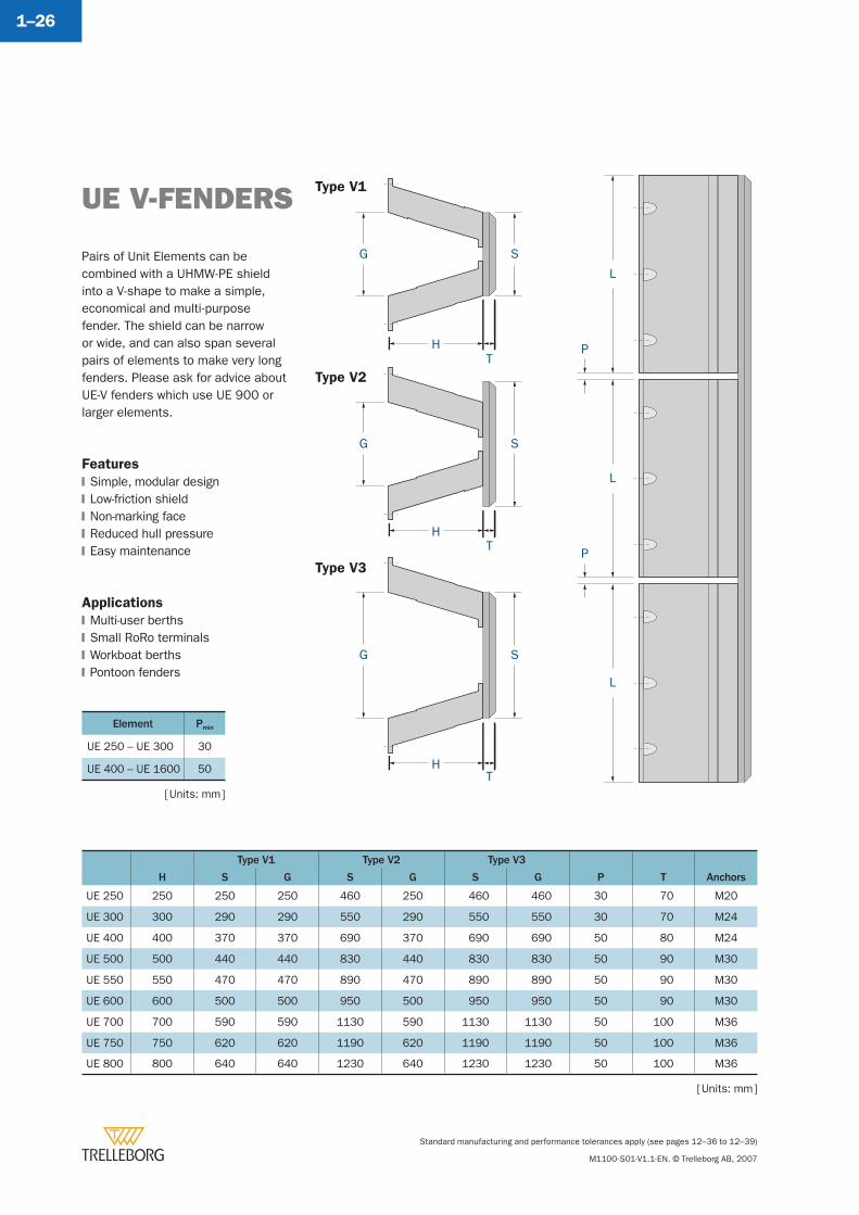
Type V1
Type V2
Type V3
Pairs of Unit Elements can be combined with a UHMW-PE shield into a V-shape to make a simple, economical and multi-purpose fender. The shield can be narrow or wide, and can also span several pairs of elements to make very long fenders. Please ask for advice about UE-V fenders which use UE 900 or larger elements.
Features
Simple, modular designLow-friction shieldNon-marking faceReduced hull pressureEasy maintenance
Applications
Multi-user berthsSmall RoRo terminalsWorkboat berthsPontoon fenders
�
�
�
�
�
�
�
�
�
H
Type V1 Type V2 Type V3
P T AnchorsS G S G S G
UE 250 250 250 250 460 250 460 460 30 70 M20
UE 300 300 290 290 550 290 550 550 30 70 M24
UE 400 400 370 370 690 370 690 690 50 80 M24
UE 500 500 440 440 830 440 830 830 50 90 M30
UE 550 550 470 470 890 470 890 890 50 90 M30
UE 600 600 500 500 950 500 950 950 50 90 M30
UE 700 700 590 590 1130 590 1130 1130 50 100 M36
UE 750 750 620 620 1190 620 1190 1190 50 100 M36
UE 800 800 640 640 1230 640 1230 1230 50 100 M36
UE V-FENDERS
[ Units: mm ]
Element Pmin
UE 250 – UE 300 30
UE 400 – UE 1600 50
[ Units: mm ]
UE V-FENDERS
Standard manufacturing and performance tolerances apply (see pages 12–36 to 12–39)
M1100-S01-V1.1-EN. © Trelleborg AB, 2007
1–27
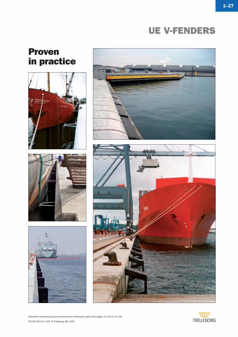
Provenin practice
Standard manufacturing and performance tolerances apply (see pages 12–36 to 12–39)
M1100-S01-V1.1-EN. © Trelleborg AB, 2007
1–28
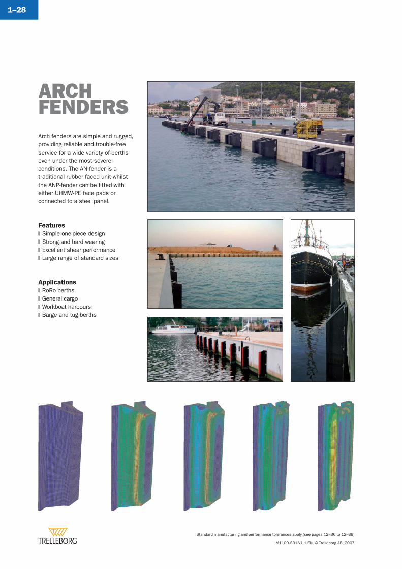
Arch fenders are simple and rugged, providing reliable and trouble-free service for a wide variety of berths even under the most severe conditions. The AN-fender is a traditional rubber faced unit whilst the ANP-fender can be fi tted with either UHMW-PE face pads or connected to a steel panel.
Features
Simple one-piece designStrong and hard wearingExcellent shear performanceLarge range of standard sizes
Applications
RoRo berthsGeneral cargoWorkboat harboursBarge and tug berths
�
�
�
�
�
�
�
�
ARCH FENDERS
ARCH FENDERS
Standard manufacturing and performance tolerances apply (see pages 12–36 to 12–39)
M1100-S01-V1.1-EN. © Trelleborg AB, 2007
1–29
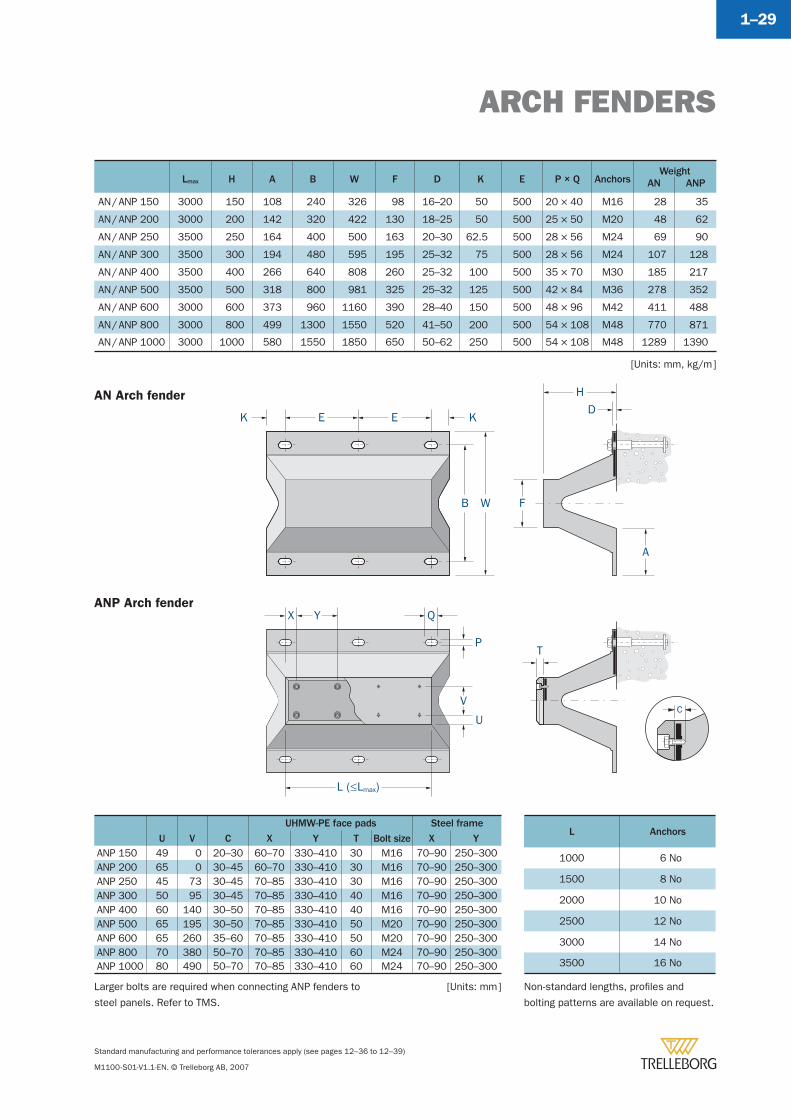
Lmax H A B W F D K E P × Q AnchorsWeight
AN ANP
AN / ANP 150 3000 150 108 240 326 98 16–20 50 500 20 × 40 M16 28 35
AN / ANP 200 3000 200 142 320 422 130 18–25 50 500 25 × 50 M20 48 62
AN / ANP 250 3500 250 164 400 500 163 20–30 62.5 500 28 × 56 M24 69 90
AN / ANP 300 3500 300 194 480 595 195 25–32 75 500 28 × 56 M24 107 128
AN / ANP 400 3500 400 266 640 808 260 25–32 100 500 35 × 70 M30 185 217
AN / ANP 500 3500 500 318 800 981 325 25–32 125 500 42 × 84 M36 278 352
AN / ANP 600 3000 600 373 960 1160 390 28–40 150 500 48 × 96 M42 411 488
AN / ANP 800 3000 800 499 1300 1550 520 41–50 200 500 54 × 108 M48 770 871
AN / ANP 1000 3000 1000 580 1550 1850 650 50–62 250 500 54 × 108 M48 1289 1390
UHMW-PE face pads Steel frame
U V C X Y T Bolt size X YANP 150 49 0 20–30 60–70 330–410 30 M16 70–90 250–300ANP 200 65 0 30–45 60–70 330–410 30 M16 70–90 250–300ANP 250 45 73 30–45 70–85 330–410 30 M16 70–90 250–300ANP 300 50 95 30–45 70–85 330–410 40 M16 70–90 250–300ANP 400 60 140 30–50 70–85 330–410 40 M16 70–90 250–300ANP 500 65 195 30–50 70–85 330–410 50 M20 70–90 250–300ANP 600 65 260 35–60 70–85 330–410 50 M20 70–90 250–300ANP 800 70 380 50–70 70–85 330–410 60 M24 70–90 250–300ANP 1000 80 490 50–70 70–85 330–410 60 M24 70–90 250–300
L Anchors
1000 6 No
1500 8 No
2000 10 No
2500 12 No
3000 14 No
3500 16 No
AN Arch fender
ANP Arch fender
[Units: mm, kg/m ]
K E E K
B W
D
H
F
A
Q
P
L (≤Lmax)
V
U
X Y
T
C
Non-standard lengths, profi les and
bolting patterns are available on request.
[Units: mm ]Larger bolts are required when connecting ANP fenders to
steel panels. Refer to TMS.
AN FENDER
Standard manufacturing and performance tolerances apply (see pages 12–36 to 12–39)
M1100-S01-V1.1-EN. © Trelleborg AB, 2007
1–30
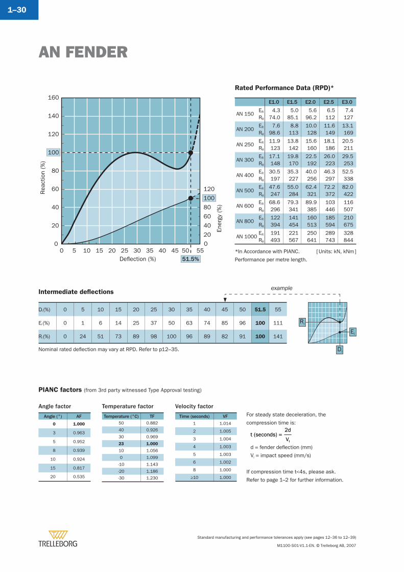
E1.0 E1.5 E2.0 E2.5 E3.0
AN 150ER
RR
4.374.0
5.085.1
5.696.2
6.5112
7.4127
AN 200ER
RR
7.698.6
8.8113
10.0128
11.6149
13.1169
AN 250ER
RR
11.9123
13.8142
15.6160
18.1186
20.5211
AN 300ER
RR
17.1148
19.8170
22.5192
26.0223
29.5253
AN 400ER
RR
30.5197
35.3227
40.0256
46.3297
52.5338
AN 500ER
RR
47.6247
55.0284
62.4321
72.2372
82.0422
AN 600ER
RR
68.6296
79.3341
89.9385
103446
116507
AN 800ER
RR
122394
141454
160513
185594
210675
AN 1000ER
RR
191493
221567
250641
289743
328844
*In Accordance with PIANC.
Performance per metre length.
Rea
ctio
n (%
)
Ener
gy (
%)
Deflection (%)
0
20
40
60
80
100
120
140
160
0 5 10 15 20 25 30 35 40 45 50 5551.5%
0
40
20
60
80
100
120
Intermediate defl ections
Di (%) 0 5 10 15 20 25 30 35 40 45 50 51.5 55
Ei (%) 0 1 6 14 25 37 50 63 74 85 96 100 111
Ri (%) 0 24 51 73 89 98 100 96 89 82 91 100 141Ei
Ri
Di
[ Units: kN, kNm ]
example
Angle factor
Angle (°) AF
0 1.000
3 0.963
5 0.952
8 0.939
10 0.924
15 0.817
20 0.535
For steady state deceleration, the
compression time is:
d = fender defl ection (mm)
Vi = impact speed (mm/s)
If compression time t<4s, please ask.
Refer to page 1–2 for further information.
Vi
2dt (seconds) =
Vi
2dt (seconds) =
Temperature factor
Temperature (°C) TF50 0.882
40 0.926
30 0.969
23 1.000
10 1.056
0 1.099
-10 1.143
-20 1.186
-30 1.230
Velocity factor
Time (seconds) VF
1 1.014
2 1.005
3 1.004
4 1.003
5 1.003
6 1.002
8 1.000
≥10 1.000
PIANC factors (from 3rd party witnessed Type Approval testing)
Rated Performance Data (RPD)*
Nominal rated defl ection may vary at RPD. Refer to p12–35.
ANP FENDER
Standard manufacturing and performance tolerances apply (see pages 12–36 to 12–39)
M1100-S01-V1.1-EN. © Trelleborg AB, 2007
1–31
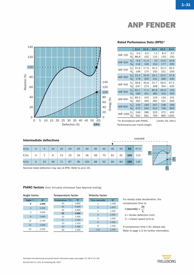
Intermediate defl ections
Di (%) 0 5 10 15 20 25 30 35 40 45 50 54 57.5
Ei (%) 0 1 6 13 23 34 46 58 70 81 91 100 110
Ri (%) 0 23 49 71 87 96 100 98 92 84 84 100 139Ei
Ri
Di
E1.0 E1.5 E2.0 E2.5 E3.0
ANP 150ER
RR
5.688.8
6.5102
7.3115
8.4133
9.5150
ANP 200ER
RR
9.9118
11.4136
13154
14.9177
16.8200
ANP 250ER
RR
15.6148
17.9170
20.2192
23.3221
26.3250
ANP 300ER
RR
22.4178
25.8205
29.1231
33.5266
37.8300
ANP 400ER
RR
39.8237
45.8273
51.7308
59.5354
67.2400
ANP 500ER
RR
62.1296
71.5341
80.8385
92.9443
105500
ANP 600ER
RR
89.3355
103409
116462
134531
151600
ANP 800ER
RR
159473
183544
207615
238708
269800
ANP 1000ER
RR
249592
286681
323769
372885
4201000
*In Accordance with PIANC.
Performance per metre length.
Rea
ctio
n (%
)
Ener
gy (
%)
Deflection (%)
0
20
40
60
80
100
120
140
0 5 10 15 20 25 30 35 40 45 50 5554%
0
40
20
60
80
100
120
140
[ Units: kN, kNm ]
example
For steady state deceleration, the
compression time is:
d = fender defl ection (mm)
Vi = impact speed (mm/s)
If compression time t<4s, please ask.
Refer to page 1–2 for further information.
Vi
2dt (seconds) =
Vi
2dt (seconds) =
Temperature factor
Temperature (°C) TF50 0.882
40 0.926
30 0.969
23 1.000
10 1.056
0 1.099
-10 1.143
-20 1.186
-30 1.230
Velocity factor
Time (seconds) VF
1 1.008
2 1.003
3 1.002
4 1.001
5 1.000
6 1.000
8 1.000
≥10 1.000
PIANC factors (from 3rd party witnessed Type Approval testing)
Angle factor
Angle (°) AF
0 1.000
3 0.945
5 0.905
8 0.840
10 0.794
15 0.669
20 0.529
Rated Performance Data (RPD)*
Nominal rated defl ection may vary at RPD. Refer to p12–35.
Standard manufacturing and performance tolerances apply (see pages 12–36 to 12–39)
M1100-S01-V1.1-EN. © Trelleborg AB, 2007
1–32
Other corner fender solutions
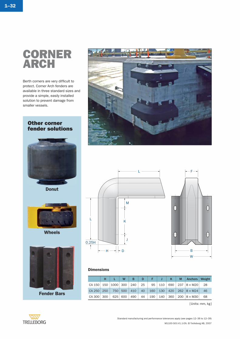
Dimensions
H L W B D F J K M Anchors Weight
CA 150 150 1000 300 240 25 95 110 690 237 8 × M20 28
CA 250 250 750 500 410 40 160 130 420 262 8 × M24 46
CA 300 300 625 600 490 44 190 140 360 200 8 × M30 68
Berth corners are very diffi cult to protect. Corner Arch fenders are available in three standard sizes and provide a simple, easily installed solution to prevent damage from smaller vessels.
CORNER ARCH
J
K
L
M
F
D
L
0.25H
H B
W
Donut
Wheels
Fender Bars
[ Units: mm, kg ]
ARCH FENDERS
Standard manufacturing and performance tolerances apply (see pages 12–36 to 12–39)
M1100-S01-V1.1-EN. © Trelleborg AB, 2007
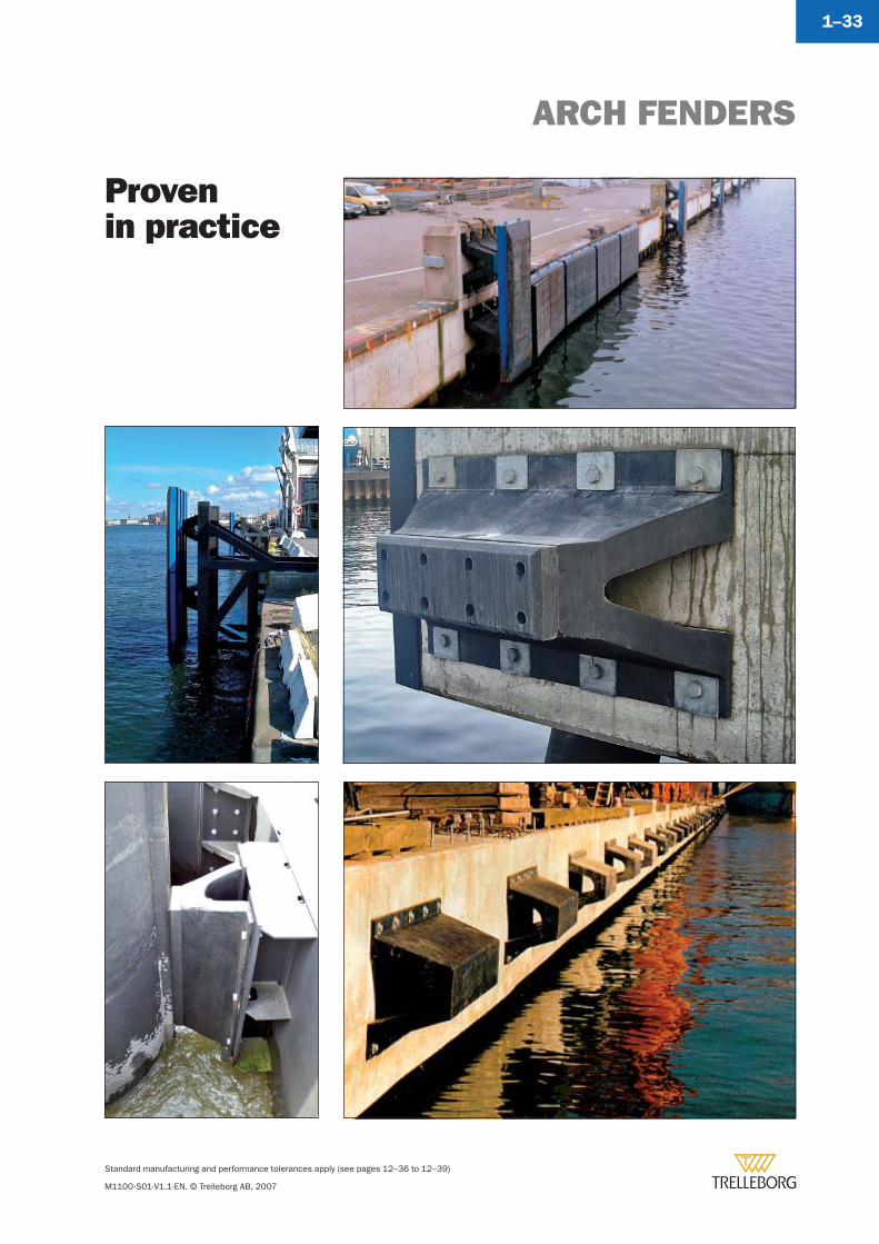
1–33
Provenin practice

MV ElementsV FendersMI Elements
Modular Fenders
Ref. M1100-S02-V1.1-EN
Section 2
www.trelleborg.com/marine
Trelleborg Marine Systems
Standard manufacturing and performance tolerances apply (see pages 12–36 to 12–39)
M1100-S02-V1.1-EN. © Trelleborg AB, 2007
2–2
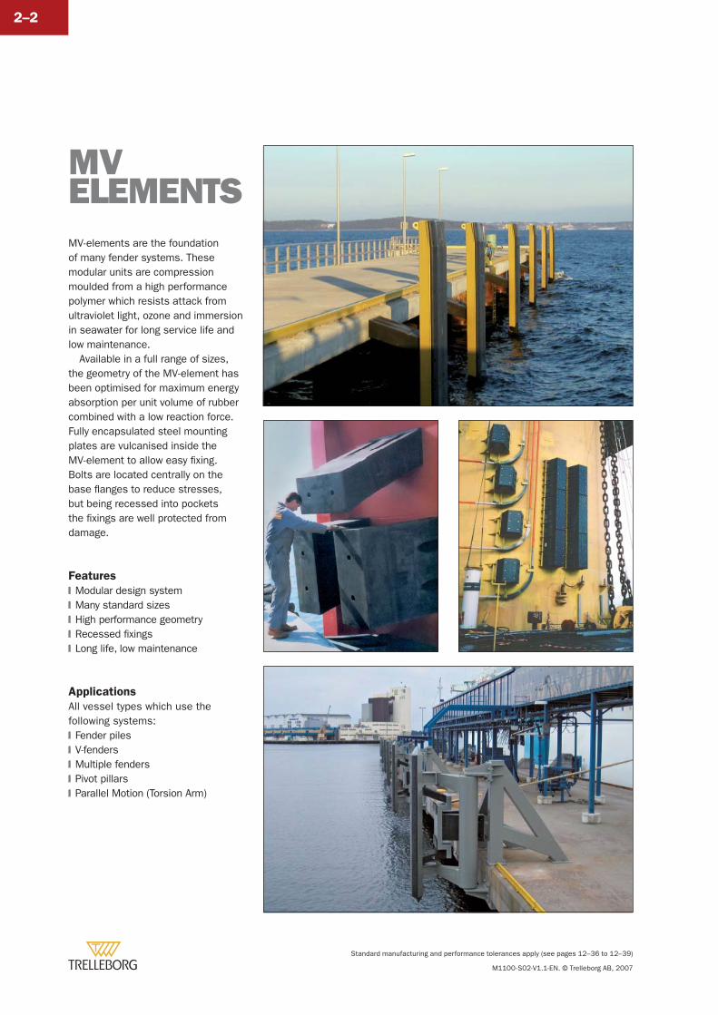
MV-elements are the foundation of many fender systems. These modular units are compression moulded from a high performance polymer which resists attack from ultraviolet light, ozone and immersion in seawater for long service life and low maintenance.
Available in a full range of sizes, the geometry of the MV-element has been optimised for maximum energy absorption per unit volume of rubber combined with a low reaction force. Fully encapsulated steel mounting plates are vulcanised inside the MV-element to allow easy fi xing. Bolts are located centrally on the base fl anges to reduce stresses, but being recessed into pockets the fi xings are well protected from damage.
Features
Modular design systemMany standard sizesHigh performance geometryRecessed fi xingsLong life, low maintenance
Applications
All vessel types which use the following systems:
Fender pilesV-fendersMultiple fendersPivot pillarsParallel Motion (Torsion Arm)
�
�
�
�
�
�
�
�
�
�
MV ELEMENTS
MV ELEMENT
Standard manufacturing and performance tolerances apply (see pages 12–36 to 12–39)
M1100-S02-V1.1-EN. © Trelleborg AB, 2007
2–3
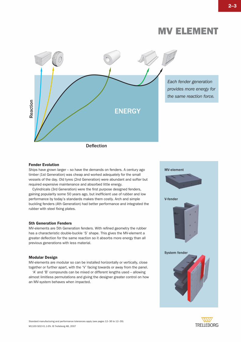
Fender Evolution
Ships have grown larger – so have the demands on fenders. A century ago timber (1st Generation) was cheap and worked adequately for the small vessels of the day. Old tyres (2nd Generation) were abundant and softer but required expensive maintenance and absorbed little energy.
Cylindricals (3rd Generation) were the fi rst purpose designed fenders, gaining popularity some 50 years ago, but ineffi cient use of rubber and low performance by today’s standards makes them costly. Arch and simple buckling fenders (4th Generation) had better performance and integrated the rubber with steel fi xing plates.
5th Generation Fenders
MV-elements are 5th Generation fenders. With refi ned geometry the rubber has a characteristic double-buckle ‘S’ shape. This gives the MV-element a greater defl ection for the same reaction so it absorbs more energy than all previous generations with less material.
Modular Design
MV-elements are modular so can be installed horizontally or vertically, close together or further apart, with the ‘V’ facing towards or away from the panel.
‘A’ and ‘B’ compounds can be mixed or different lengths used – allowing almost limitless permutations and giving the designer greater control on how an MV-system behaves when impacted.
ENERGY
Rea
ctio
n
Deflection
Each fender generation
provides more energy for
the same reaction force.
MV-element
V-fender
System fender
MV ELEMENT
Standard manufacturing and performance tolerances apply (see pages 12–36 to 12–39)
M1100-S02-V1.1-EN. © Trelleborg AB, 2007
2–4
L B C D E F G J T Anchor Holes Weight
MV300
600
150 300 150 300 94 93 47 17 M20
2 + 2 27
900 3 + 3 41
1200 4 + 4 54
1500 5 + 5 68
MV400
750 125
500
125
500 125 124 63 17 M24
2 + 2 50
1000 250 250 2 + 2 66
1500 250 250 3 + 3 99
2000 250 250 4 + 4 132
2500 250 250 5 + 5 165
3000 250 250 6 + 6 198
MV500
750 125
500
125
500 158 142 87 20 M30
2 + 2 84
1000
250 250
2 + 2 111
1500 3 + 3 167
2000 4 + 4 222
2500 5 + 5 278
3000 6 + 6 334
MV550
750 125
500
125
500 172 170 87 20 M30
2 + 2 100
1000250 250
2 + 2 132
1500 3 + 3 200
MV600
750 125
500
125
500 188 199 87 20 M30
2 + 2 115
1000250 250
2 + 2 153
1500 3 + 3 230
MV750
750 125
500
125
500 235 230 118 26 M36
2 + 2 180
1000250 250
2 + 2 239
1500 3 + 3 359
MV800
800 150
500
150
500 250 240 129 26 M36
2 + 2 214
1000
250 250
2 + 2 268
1500 3 + 3 402
2000 4 + 4 536
MV1000
800 150
500
150
500 322 310 162 31 M42
2 + 2 346
850 175 175 2 + 2 368
900 200 200 2 + 2 389
950 225 225 2 + 2 411
1000 250 250 2 + 2 432
1050 275 275 2 + 2 454
1100 300 300 2 + 2 476
1150 325 325 2 + 2 497
1200 350 350 2 + 2 519
1500250 250
3 + 3 648
2000 4 + 4 864
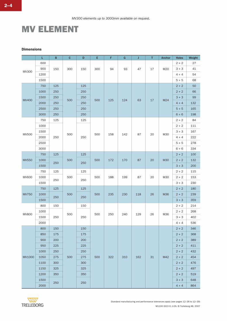
MV300 elements up to 3000mm available on request.
Dimensions
MV ELEMENT
Standard manufacturing and performance tolerances apply (see pages 12–36 to 12–39)
M1100-S02-V1.1-EN. © Trelleborg AB, 2007
2–5
L B C D E F G J T Anchor Holes Weight
MV1250
800 150
500
150
500 401 388 202 36 M48
2 + 2 511
850 175 175 2 + 2 543
900 200 200 2 + 2 575
950 225 225 2 + 2 607
1000 250 250 2 + 2 639
1050 275 275 2 + 2 671
1100 300 300 2 + 2 703
1150 325 325 2 + 2 735
1200 350 350 2 + 2 767
1250 375 375 2 + 2 799
1500250 250
3 + 3 959
2000 4 + 4 1278
MV1450
900 200
500
200
500 454 445 228 41 M48
2 + 2 786
1000 250 250 2 + 2 873
1100 300 300 2 + 2 960
1200 350 350 2 + 2 1048
1500250 250
3 + 3 1310
2000 4 + 4 1746
MV1600
1000 250
500
250
500 507 480 261 50 M56
2 + 2 1114
1100 300 300 2 + 2 1226
1200 350 350 2 + 2 1337
1500250 250
3 + 3 1671
2000 4 + 4 2228
D E E D
B C C BL
G
FJ
H
T
F
Internalsteel plate
M
T
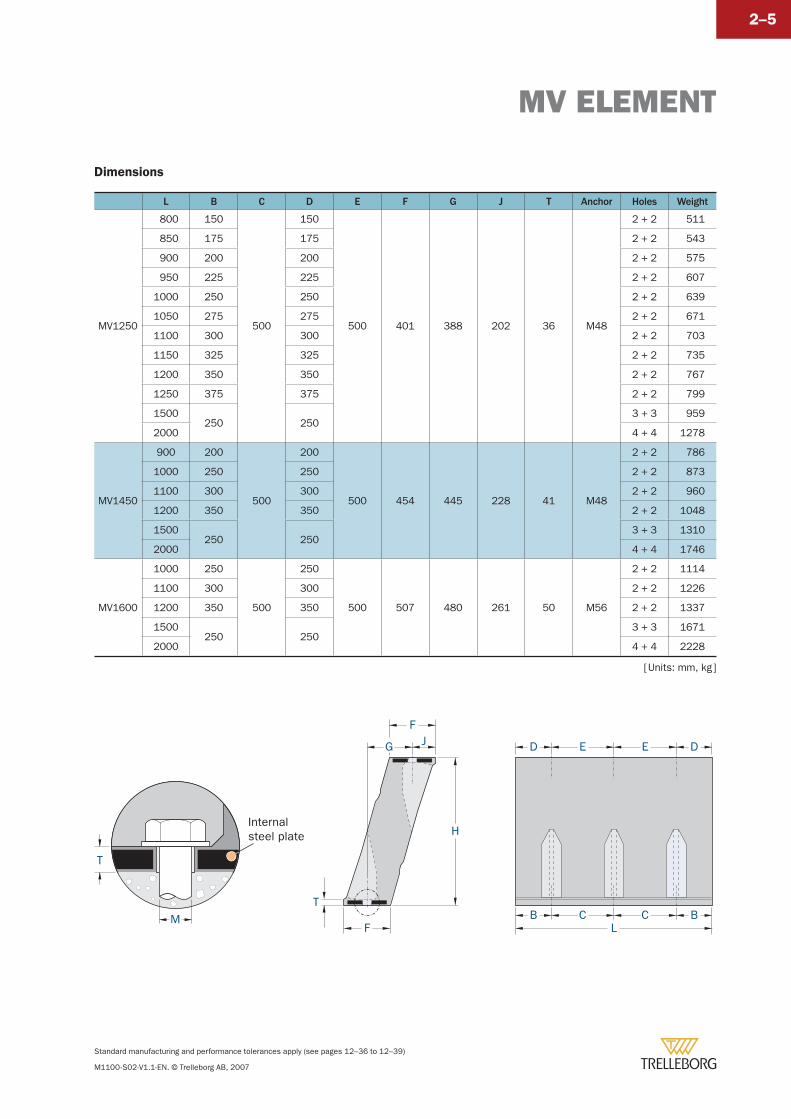
[ Units: mm, kg ]
Dimensions
MV ELEMENT
Standard manufacturing and performance tolerances apply (see pages 12–36 to 12–39)
M1100-S02-V1.1-EN. © Trelleborg AB, 2007
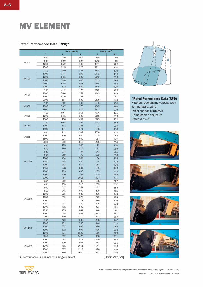
2–6
LCompound A Compound B
E R E R
MV300
600 12.6 91.4 8.8 64
900 18.9 137 13.2 961200 25.2 183 17.7 1281500 31.5 229 22.1 160
MV400
750 26.9 146 18.8 1021000 37.4 203 26.2 1421500 56.1 305 39.3 2132000 74.8 406 52.3 2842500 93.5 508 65.4 3563000 112 609 78.5 427
MV500
750 41.2 179 28.9 1251000 58.4 254 40.9 1781500 87.6 381 61.3 2672000 117 508 81.8 356
MV550 750 49.9 197 34.9 1381000 70.7 279 49.5 1961500 106 419 74.2 293
MV600 750 59.4 215 41.6 1511000 84.1 305 58.9 2131500 126 457 88.3 320
MV750 750 90.4 262 63.2 1831000 131 381 92 2671500 197 571 138 400
MV800
800 111 302 77.8 2121000 150 406 105 2841500 224 609 157 4272000 299 813 209 569
MV1000
800 175 380 122 266
850 189 412 133 288
900 204 444 143 311
950 219 476 153 3331000 234 508 164 3561050 248 540 174 3781100 263 572 184 4001150 278 604 195 4231200 293 636 205 4451500 350 762 245 5332000 467 1016 327 711
MV1250
800 269 468 188 327
850 293 510 205 357
900 317 551 222 386
950 341 593 239 4151000 365 635 256 4441050 389 677 272 4741100 413 718 289 5031150 437 760 306 5321200 461 802 323 5611250 485 844 340 5911500 548 952 383 6672000 730 1270 511 889
MV1450
900 426 638 298 4471000 491 736 344 5161100 557 835 390 5841200 622 933 436 6531500 737 1105 516 7732000 982 1473 688 1031
MV1600
1000 598 813 419 5691100 690 937 483 6561200 781 1061 547 7431500 897 1219 628 8532000 1196 1625 837 1138
L
d
R
H
F
All performance values are for a single element. [ Units: kNm, kN ]
Rated Performance Data (RPD)*
*Rated Performance Data (RPD)
Method: Decreasing Velocity (DV)Temperature: 23ºCInitial speed: 150mm/s Compression angle: 0ºRefer to p2–7.
MV ELEMENT
Standard manufacturing and performance tolerances apply (see pages 12–36 to 12–39)
M1100-S02-V1.1-EN. © Trelleborg AB, 2007
2–7
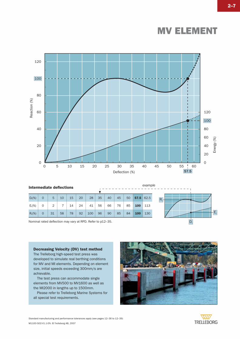
Decreasing Velocity (DV) test method
The Trelleborg high-speed test press was developed to simulate real berthing conditions for MV and MI elements. Depending on element size, initial speeds exceeding 300mm/s are achievable.
The test press can accommodate single elements from MV500 to MV1600 as well as the MI2000 in lengths up to 1500mm.
Please refer to Trelleborg Marine Systems for all special test requirements.
Intermediate defl ections
Di (%) 0 5 10 15 20 28 35 40 45 50 57.5 62.5
Ei (%) 0 2 7 14 24 41 56 66 76 85 100 113
Ri (%) 0 31 58 78 92 100 96 90 85 84 100 130 Ei
Di
Ri
example
Rea
ctio
n (%
)
Ener
gy (
%)
Deflection (%)
100
0 5 10 15 20 25 30 35 40 45 50 55 6057.5
100
0
20
40
60
80
120
0
20
40
60
80
120
Nominal rated defl ection may vary at RPD. Refer to p12–35.
MV SYSTEMS
Standard manufacturing and performance tolerances apply (see pages 12–36 to 12–39)
M1100-S02-V1.1-EN. © Trelleborg AB, 2007
2–8
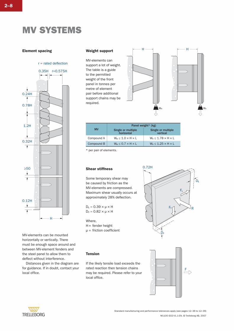
r=0.575H0.35H
H
0.24H
0.78H
1.2H
0.32H
0.12H
≥50
r = rated deflection
Element spacing
MV-elements can be mounted horizontally or vertically. There must be enough space around and between MV-element fenders and the steel panel to allow them to defl ect without interference.
Distances given in the diagram are for guidance. If in doubt, contact your local offi ce.
Weight support
MV-elements can support a lot of weight. The table is a guide to the permitted weight of the front panel in tonnes per metre of element pair before additional support chains may be required.
Shear stiffness
Some temporary shear may be caused by friction as the MV-elements are compressed. Maximum shear usually occurs at approximately 28% defl ection.
DL ≈ 0.39 × μ × HDT ≈ 0.82 × μ × H
Where,H = fender heightμ = friction coeffi cient
Tension
If the likely tensile load exceeds the rated reaction then tension chains may be required. Please refer to your local offi ce.
F
H
WH WV
H
0.72H
R
DL
FL
FT
DT
MVPanel weight* (kg)
Single or multiplehorizontal
Single or multiplevertical
Compound A WH ≤ 1.0 × H × L WV ≤ 1.78 × H × L
Compound B WH ≤ 0.7 × H × L WV ≤ 1.25 × H × L
* per pair of elements.
MV SYSTEMS
Standard manufacturing and performance tolerances apply (see pages 12–36 to 12–39)
M1100-S02-V1.1-EN. © Trelleborg AB, 2007
2–9
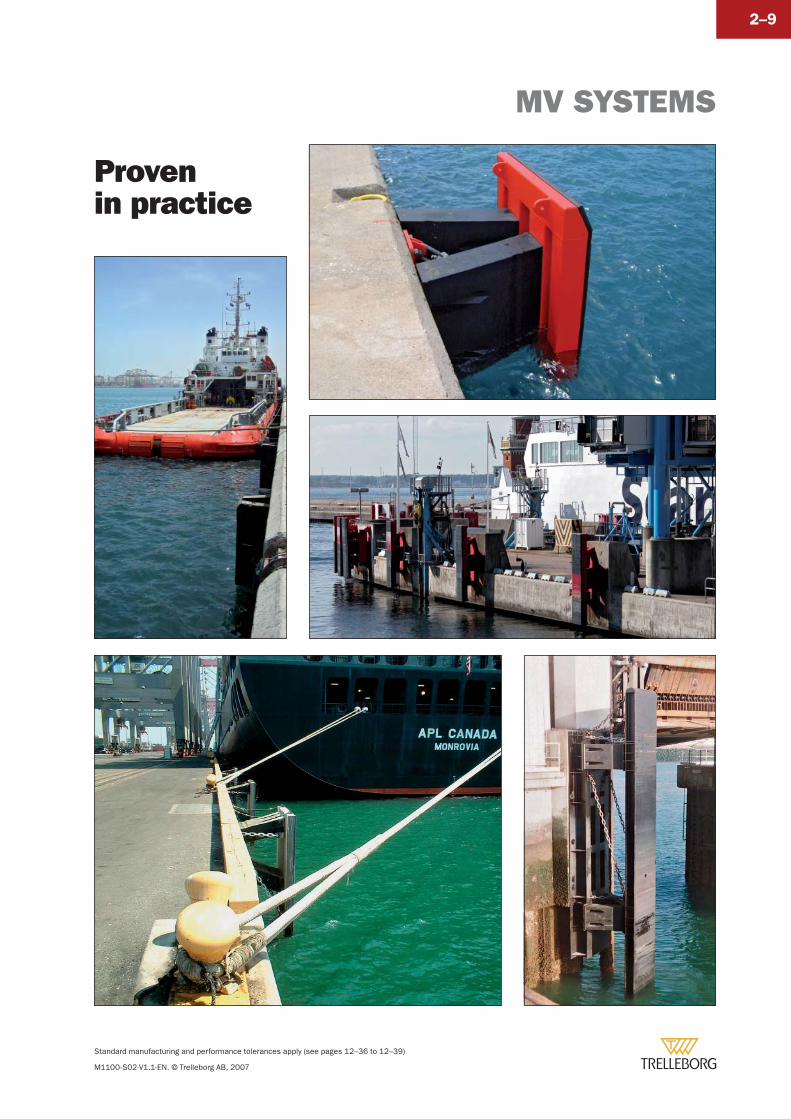
Provenin practice
Standard manufacturing and performance tolerances apply (see pages 12–36 to 12–39)
M1100-S02-V1.1-EN. © Trelleborg AB, 2007
2–10
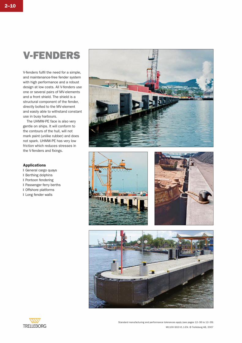
V-fenders fulfi l the need for a simple, and maintenance-free fender system with high performance and a robust design at low costs. All V-fenders use one or several pairs of MV-elements and a front shield. The shield is a structural component of the fender, directly bolted to the MV-element and easily able to withstand constant use in busy harbours.
The UHMW-PE face is also very gentle on ships. It will conform to the contours of the hull, will not mark paint (unlike rubber) and does not spark. UHMW-PE has very low friction which reduces stresses in the V-fenders and fi xings.
Applications
General cargo quaysBerthing dolphinsPontoon fenderingPassenger ferry berthsOffshore platformsLong fender walls
�
�
�
�
�
�
V-FENDERS
V-FENDERS
Standard manufacturing and performance tolerances apply (see pages 12–36 to 12–39)
M1100-S02-V1.1-EN. © Trelleborg AB, 2007
2–11
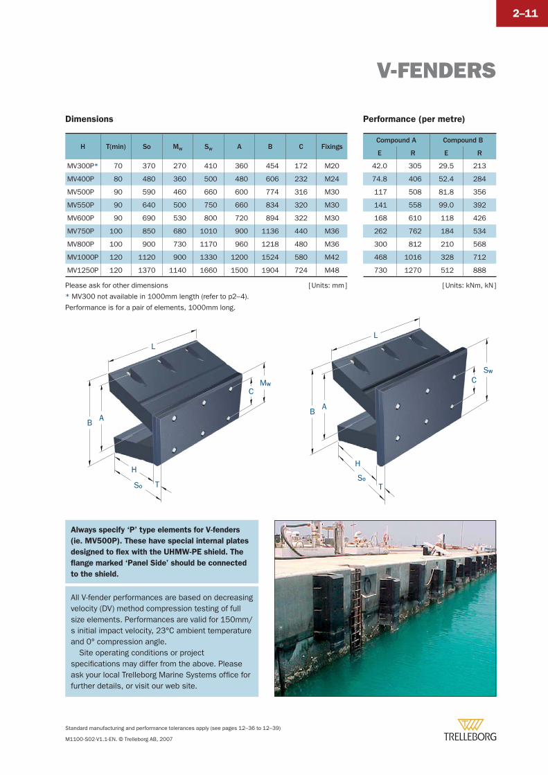
* MV300 not available in 1000mm length (refer to p2–4).
Performance is for a pair of elements, 1000mm long.
H T(min) So MW SW A B C Fixings
MV300P* 70 370 270 410 360 454 172 M20
MV400P 80 480 360 500 480 606 232 M24
MV500P 90 590 460 660 600 774 316 M30
MV550P 90 640 500 750 660 834 320 M30
MV600P 90 690 530 800 720 894 322 M30
MV750P 100 850 680 1010 900 1136 440 M36
MV800P 100 900 730 1170 960 1218 480 M36
MV1000P 120 1120 900 1330 1200 1524 580 M42
MV1250P 120 1370 1140 1660 1500 1904 724 M48
Compound A Compound B
E R E R
42.0 305 29.5 213
74.8 406 52.4 284
117 508 81.8 356
141 558 99.0 392
168 610 118 426
262 762 184 534
300 812 210 568
468 1016 328 712
730 1270 512 888
Dimensions Performance (per metre)
[ Units: mm ] [ Units: kNm, kN ]Please ask for other dimensions
All V-fender performances are based on decreasing velocity (DV) method compression testing of full size elements. Performances are valid for 150mm/s initial impact velocity, 23°C ambient temperature and 0° compression angle.
Site operating conditions or project specifi cations may differ from the above. Please ask your local Trelleborg Marine Systems offi ce for further details, or visit our web site.
B
C
H
TSO
MW
AB
C
H
L
TSO
SW
A
L
Always specify ‘P’ type elements for V-fenders
(ie. MV500P). These have special internal plates
designed to fl ex with the UHMW-PE shield. The
fl ange marked ‘Panel Side’ should be connected
to the shield.
Standard manufacturing and performance tolerances apply (see pages 12–36 to 12–39)
M1100-S02-V1.1-EN. © Trelleborg AB, 2007
2–12
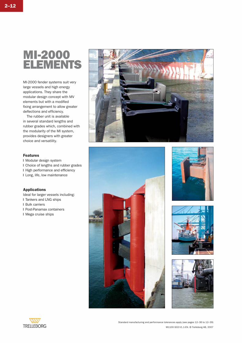
MI-2000 fender systems suit very large vessels and high energy applications. They share the modular design concept with MV elements but with a modifi ed fi xing arrangement to allow greater defl ections and effi ciency.
The rubber unit is available in several standard lengths and rubber grades which, combined with the modularity of the MI system, provides designers with greater choice and versatility.
Features
Modular design systemChoice of lengths and rubber gradesHigh performance and effi ciencyLong, life, low maintenance
Applications
Ideal for larger vessels including:Tankers and LNG shipsBulk carriersPost-Panamax containersMega cruise ships
�
�
�
�
�
�
�
�
MI-2000 ELEMENTS
MI-2000 ELEMENTS
Standard manufacturing and performance tolerances apply (see pages 12–36 to 12–39)
M1100-S02-V1.1-EN. © Trelleborg AB, 2007
2–13
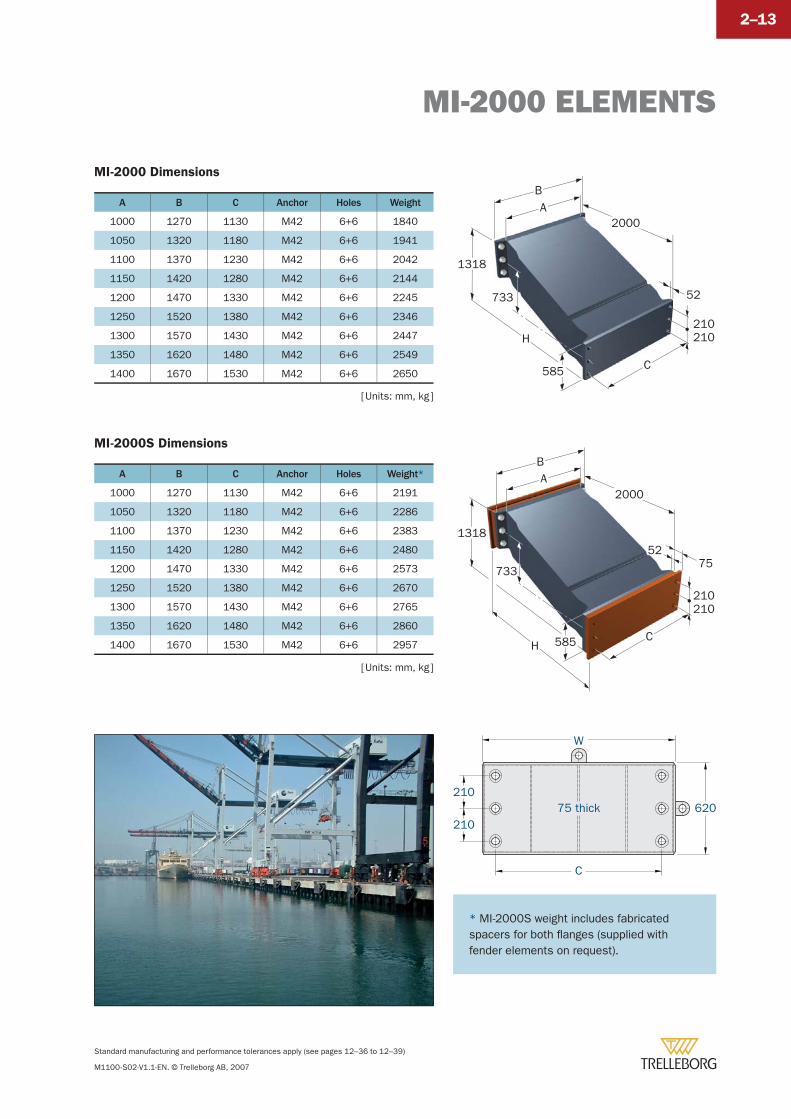
MI-2000 Dimensions
A B C Anchor Holes Weight
1000 1270 1130 M42 6+6 1840
1050 1320 1180 M42 6+6 1941
1100 1370 1230 M42 6+6 2042
1150 1420 1280 M42 6+6 2144
1200 1470 1330 M42 6+6 2245
1250 1520 1380 M42 6+6 2346
1300 1570 1430 M42 6+6 2447
1350 1620 1480 M42 6+6 2549
1400 1670 1530 M42 6+6 2650
MI-2000S Dimensions
A B C Anchor Holes Weight*
1000 1270 1130 M42 6+6 2191
1050 1320 1180 M42 6+6 2286
1100 1370 1230 M42 6+6 2383
1150 1420 1280 M42 6+6 2480
1200 1470 1330 M42 6+6 2573
1250 1520 1380 M42 6+6 2670
1300 1570 1430 M42 6+6 2765
1350 1620 1480 M42 6+6 2860
1400 1670 1530 M42 6+6 2957
[ Units: mm, kg ]
[ Units: mm, kg ]
1318
2000
HC
BA
585
733
210
7552
210
2000
H
C
BA
585
733 52
210210
1318
W
C
620210
21075 thick
* MI-2000S weight includes fabricated spacers for both fl anges (supplied with fender elements on request).
MI-2000
Standard manufacturing and performance tolerances apply (see pages 12–36 to 12–39)
M1100-S02-V1.1-EN. © Trelleborg AB, 2007
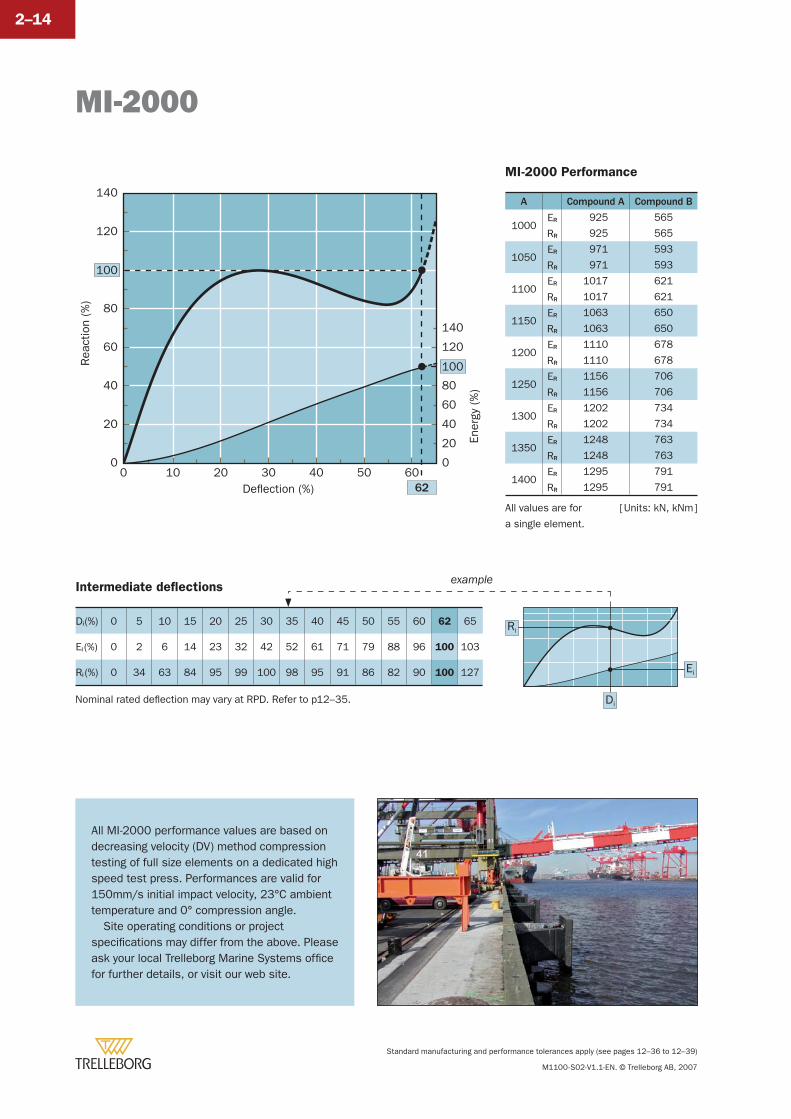
2–14
Intermediate defl ections
Di (%) 0 5 10 15 20 25 30 35 40 45 50 55 60 62 65
Ei (%) 0 2 6 14 23 32 42 52 61 71 79 88 96 100 103
Ri (%) 0 34 63 84 95 99 100 98 95 91 86 82 90 100 127 Ei
Di
Ri
example
Deflection (%)0 10 20 30 40 50 60
62
Rea
ctio
n (%
)
100
0
2020
4040
60
80
120
140
0En
ergy
(%
)
100
20
40
60
80
120
140
[ Units: kN, kNm ]
MI-2000 Performance
A Compound A Compound B
1000ER 925 565
RR 925 565
1050ER 971 593
RR 971 593
1100ER 1017 621
RR 1017 621
1150ER 1063 650
RR 1063 650
1200ER 1110 678
RR 1110 678
1250ER 1156 706
RR 1156 706
1300ER 1202 734
RR 1202 734
1350ER 1248 763
RR 1248 763
1400ER 1295 791
RR 1295 791
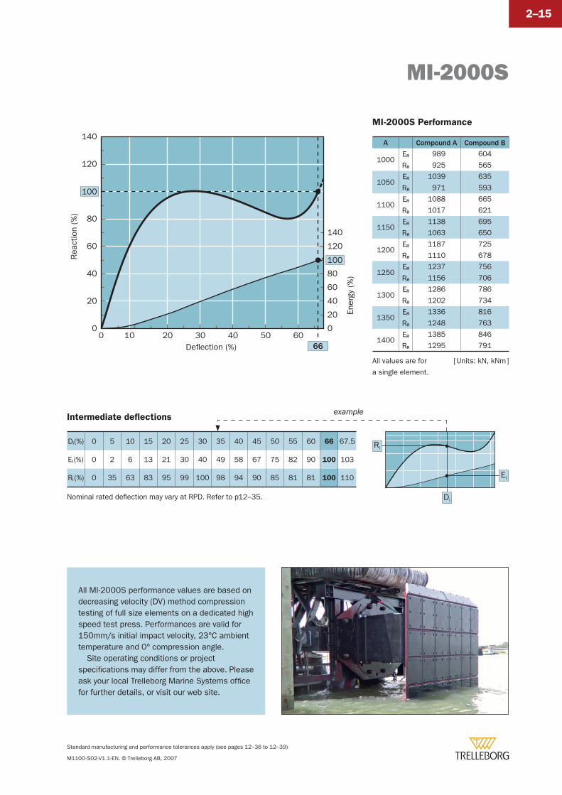
All MI-2000 performance values are based on decreasing velocity (DV) method compression testing of full size elements on a dedicated high speed test press. Performances are valid for 150mm/s initial impact velocity, 23°C ambient temperature and 0° compression angle.
Site operating conditions or project specifi cations may differ from the above. Please ask your local Trelleborg Marine Systems offi ce for further details, or visit our web site.
All values are for
a single element.
Nominal rated defl ection may vary at RPD. Refer to p12–35.
MI-2000S
Standard manufacturing and performance tolerances apply (see pages 12–36 to 12–39)
M1100-S02-V1.1-EN. © Trelleborg AB, 2007
2–15
MI-2000S Performance
A Compound A Compound B
1000ER 989 604
RR 925 565
1050ER 1039 635
RR 971 593
1100ER 1088 665
RR 1017 621
1150ER 1138 695
RR 1063 650
1200ER 1187 725
RR 1110 678
1250ER 1237 756
RR 1156 706
1300ER 1286 786
RR 1202 734
1350ER 1336 816
RR 1248 763
1400ER 1385 846
RR 1295 791
Intermediate defl ections
Di (%) 0 5 10 15 20 25 30 35 40 45 50 55 60 66 67.5
Ei (%) 0 2 6 13 21 30 40 49 58 67 75 82 90 100 103
Ri (%) 0 35 63 83 95 99 100 98 94 90 85 81 81 100 110
[ Units: kN, kNm ]
Deflection (%)0 10 20 30 40 50 60
66
Rea
ctio
n (%
)
100
0
2020
4040
60
80
120
140
0
Ener
gy (
%)
100
20
40
60
80
120
140
Ei
Di
Ri
example
All MI-2000S performance values are based on decreasing velocity (DV) method compression testing of full size elements on a dedicated high speed test press. Performances are valid for 150mm/s initial impact velocity, 23°C ambient temperature and 0° compression angle.
Site operating conditions or project specifi cations may differ from the above. Please ask your local Trelleborg Marine Systems offi ce for further details, or visit our web site.
All values are for
a single element.
Nominal rated defl ection may vary at RPD. Refer to p12–35.

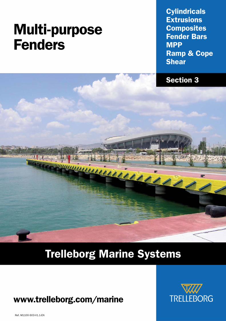
CylindricalsExtrusionsCompositesFender BarsMPPRamp & CopeShear
Multi-purposeFenders
Ref. M1100-S03-V1.1-EN
Section 3
www.trelleborg.com/marine
Trelleborg Marine Systems
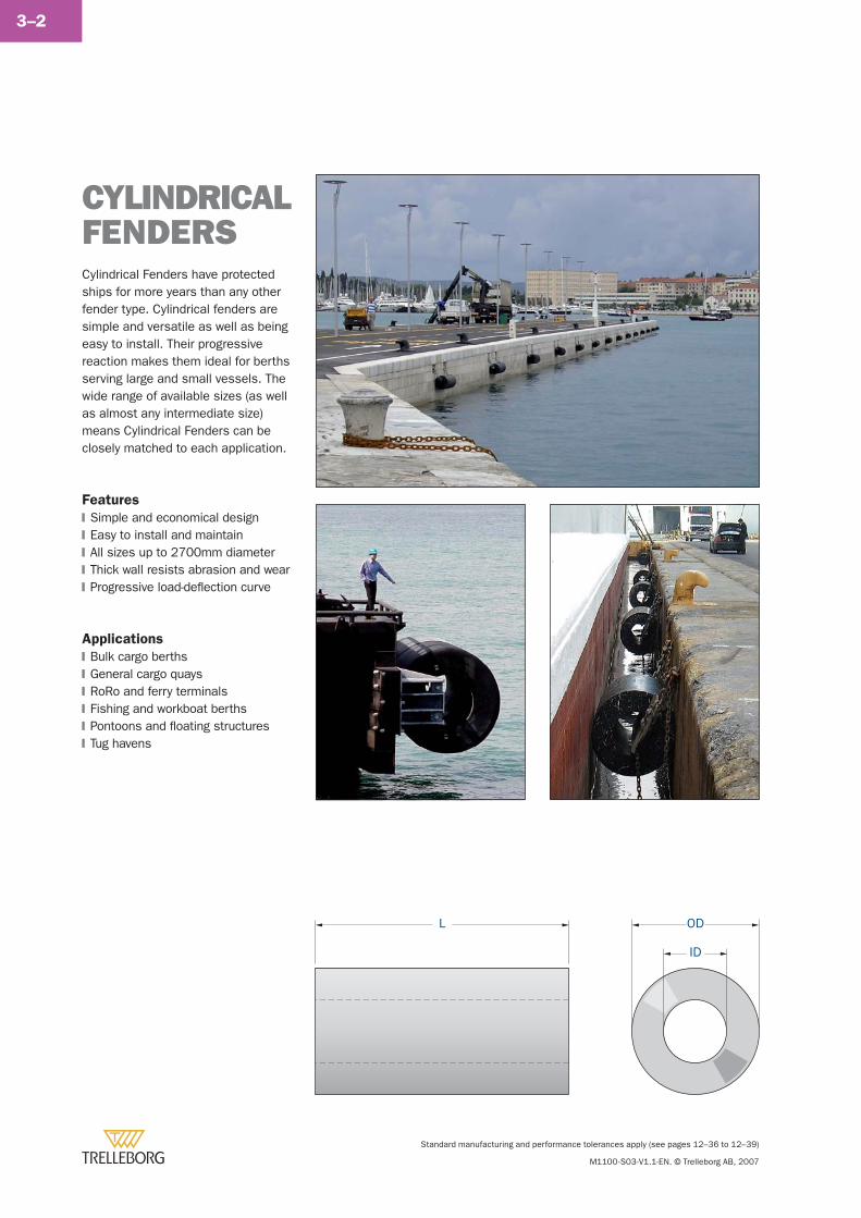
Standard manufacturing and performance tolerances apply (see pages 12–36 to 12–39)
M1100-S03-V1.1-EN. © Trelleborg AB, 2007
3–2
Cylindrical Fenders have protected ships for more years than any other fender type. Cylindrical fenders are simple and versatile as well as being easy to install. Their progressive reaction makes them ideal for berths serving large and small vessels. The wide range of available sizes (as well as almost any intermediate size) means Cylindrical Fenders can be closely matched to each application.
Features
Simple and economical designEasy to install and maintainAll sizes up to 2700mm diameterThick wall resists abrasion and wearProgressive load-defl ection curve
Applications
Bulk cargo berthsGeneral cargo quaysRoRo and ferry terminalsFishing and workboat berthsPontoons and fl oating structuresTug havens
�
�
�
�
�
�
�
�
�
�
�
CYLINDRICAL FENDERS
L OD
ID
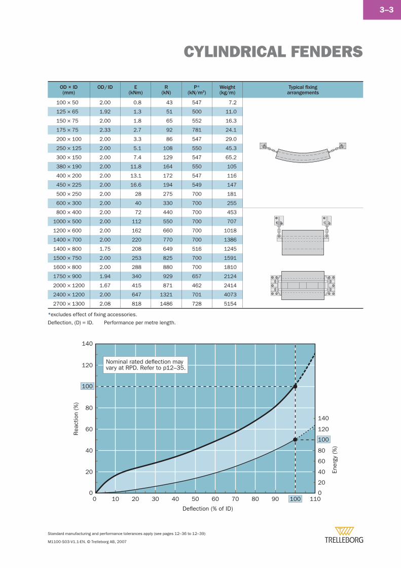
CYLINDRICAL FENDERS
Standard manufacturing and performance tolerances apply (see pages 12–36 to 12–39)
M1100-S03-V1.1-EN. © Trelleborg AB, 2007
3–3
OD × ID(mm)
OD / ID E(kNm)
R(kN)
P*(kN/m2)
Weight(kg/m)
Typical fi xingarrangements
100 × 50 2.00 0.8 43 547 7.2
125 × 65 1.92 1.3 51 500 11.0
150 × 75 2.00 1.8 65 552 16.3
175 × 75 2.33 2.7 92 781 24.1
200 × 100 2.00 3.3 86 547 29.0
250 × 125 2.00 5.1 108 550 45.3
300 × 150 2.00 7.4 129 547 65.2
380 × 190 2.00 11.8 164 550 105
400 × 200 2.00 13.1 172 547 116
450 × 225 2.00 16.6 194 549 147
500 × 250 2.00 28 275 700 181
600 × 300 2.00 40 330 700 255
800 × 400 2.00 72 440 700 453
1000 × 500 2.00 112 550 700 707
1200 × 600 2.00 162 660 700 1018
1400 × 700 2.00 220 770 700 1386
1400 × 800 1.75 208 649 516 1245
1500 × 750 2.00 253 825 700 1591
1600 × 800 2.00 288 880 700 1810
1750 × 900 1.94 340 929 657 2124
2000 × 1200 1.67 415 871 462 2414
2400 × 1200 2.00 647 1321 701 4073
2700 × 1300 2.08 818 1486 728 5154
Deflection (% of ID)
0
20
40
60
80
120
140
0 10 20 30 40 50 60 70 80 90 100 110
Rea
ctio
n (%
)
Ener
gy (%
)
100
0
40
20
60
80
120
140
100
Nominal rated deflection mayvary at RPD. Refer to p12–35.
*excludes effect of fi xing accessories.
Defl ection, (D) = ID. Performance per metre length.
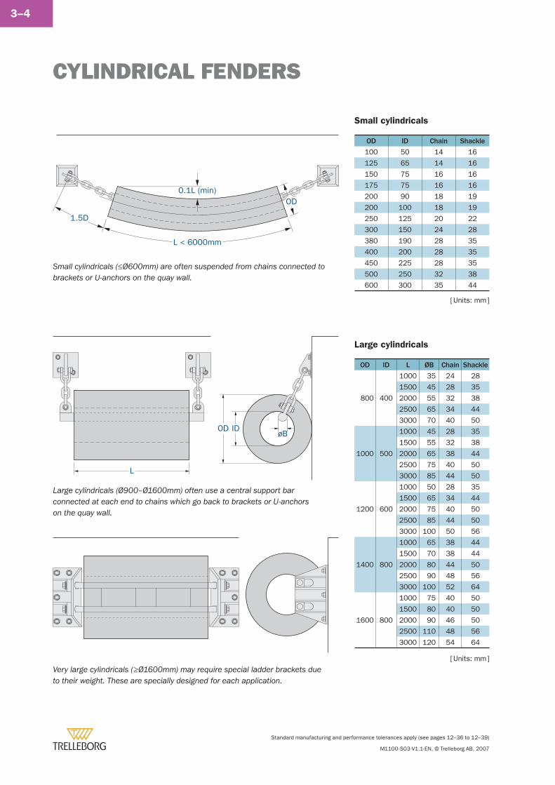
CYLINDRICAL FENDERS
Standard manufacturing and performance tolerances apply (see pages 12–36 to 12–39)
M1100-S03-V1.1-EN. © Trelleborg AB, 2007
3–4
Small cylindricals
OD ID Chain Shackle
100 50 14 16
125 65 14 16
150 75 16 16
175 75 16 16
200 90 18 19
200 100 18 19
250 125 20 22
300 150 24 28
380 190 28 35
400 200 28 35
450 225 28 35
500 250 32 38
600 300 35 44
[ Units: mm ]
Large cylindricals
OD ID L ØB Chain Shackle
800 400
1000 35 24 28
1500 45 28 35
2000 55 32 38
2500 65 34 44
3000 70 40 50
1000 500
1000 45 28 35
1500 55 32 38
2000 65 38 44
2500 75 40 50
3000 85 44 50
1200 600
1000 50 28 35
1500 65 34 44
2000 75 40 50
2500 85 44 50
3000 100 50 56
1400 800
1000 65 38 44
1500 70 38 44
2000 80 44 50
2500 90 48 56
3000 100 52 64
1600 800
1000 75 40 50
1500 80 40 50
2000 90 46 50
2500 110 48 56
3000 120 54 64
[ Units: mm ]
L
OD IDøB
L < 6000mm
1.5D
0.1L (min)OD
Small cylindricals (≤Ø600mm) are often suspended from chains connected to brackets or U-anchors on the quay wall.
Large cylindricals (Ø900–Ø1600mm) often use a central support bar connected at each end to chains which go back to brackets or U-anchors on the quay wall.
Very large cylindricals (≥Ø1600mm) may require special ladder brackets due to their weight. These are specially designed for each application.
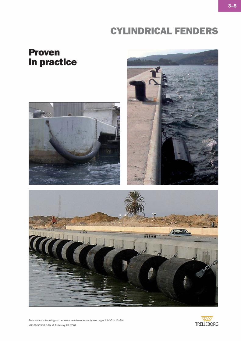
CYLINDRICAL FENDERS
Standard manufacturing and performance tolerances apply (see pages 12–36 to 12–39)
M1100-S03-V1.1-EN. © Trelleborg AB, 2007
3–5
Provenin practice
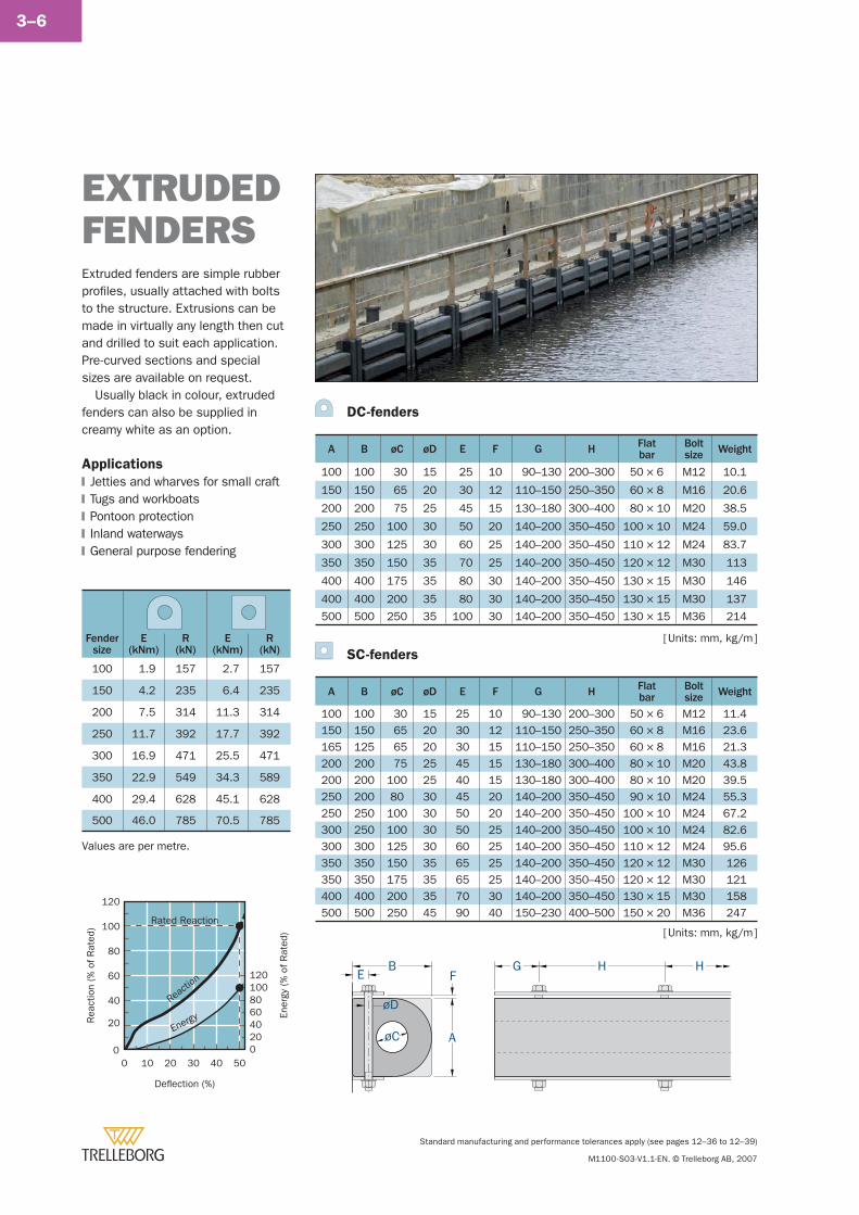
Standard manufacturing and performance tolerances apply (see pages 12–36 to 12–39)
M1100-S03-V1.1-EN. © Trelleborg AB, 2007
3–6
Deflection (%)
0 10 20 30 40 50
Rea
ctio
n (%
of R
ated
)
20
40
60
80
100
120
0
Ener
gy (%
of R
ated
)
0
4020
6080100120
Reacti
on
Energy
Rated Reaction
Fendersize
E(kNm)
R(kN)
E(kNm)
R(kN)
100 1.9 157 2.7 157
150 4.2 235 6.4 235
200 7.5 314 11.3 314
250 11.7 392 17.7 392
300 16.9 471 25.5 471
350 22.9 549 34.3 589
400 29.4 628 45.1 628
500 46.0 785 70.5 785
Values are per metre.
DC-fenders
A B øC øD E F G H Flatbar
Boltsize Weight
100 100 30 15 25 10 90–130 200–300 50 × 6 M12 10.1
150 150 65 20 30 12 110–150 250–350 60 × 8 M16 20.6
200 200 75 25 45 15 130–180 300–400 80 × 10 M20 38.5
250 250 100 30 50 20 140–200 350–450 100 × 10 M24 59.0
300 300 125 30 60 25 140–200 350–450 110 × 12 M24 83.7
350 350 150 35 70 25 140–200 350–450 120 × 12 M30 113
400 400 175 35 80 30 140–200 350–450 130 × 15 M30 146
400 400 200 35 80 30 140–200 350–450 130 × 15 M30 137
500 500 250 35 100 30 140–200 350–450 130 × 15 M36 214
SC-fenders
A B øC øD E F G H Flatbar
Boltsize Weight
100 100 30 15 25 10 90–130 200–300 50 × 6 M12 11.4150 150 65 20 30 12 110–150 250–350 60 × 8 M16 23.6165 125 65 20 30 15 110–150 250–350 60 × 8 M16 21.3200 200 75 25 45 15 130–180 300–400 80 × 10 M20 43.8200 200 100 25 40 15 130–180 300–400 80 × 10 M20 39.5250 200 80 30 45 20 140–200 350–450 90 × 10 M24 55.3250 250 100 30 50 20 140–200 350–450 100 × 10 M24 67.2300 250 100 30 50 25 140–200 350–450 100 × 10 M24 82.6300 300 125 30 60 25 140–200 350–450 110 × 12 M24 95.6350 350 150 35 65 25 140–200 350–450 120 × 12 M30 126350 350 175 35 65 25 140–200 350–450 120 × 12 M30 121400 400 200 35 70 30 140–200 350–450 130 × 15 M30 158500 500 250 45 90 40 150–230 400–500 150 × 20 M36 247
EXTRUDED FENDERS
G H HF
AøC
BE
øD
[ Units: mm, kg/m ]
[ Units: mm, kg/m ]
Extruded fenders are simple rubber profi les, usually attached with bolts to the structure. Extrusions can be made in virtually any length then cut and drilled to suit each application. Pre-curved sections and special sizes are available on request.
Usually black in colour, extruded fenders can also be supplied in creamy white as an option.
Applications
Jetties and wharves for small craftTugs and workboatsPontoon protectionInland waterwaysGeneral purpose fendering
�
�
�
�
�
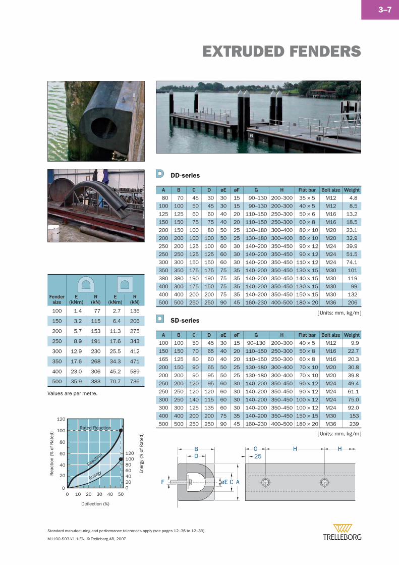
EXTRUDED FENDERS
Standard manufacturing and performance tolerances apply (see pages 12–36 to 12–39)
M1100-S03-V1.1-EN. © Trelleborg AB, 2007
3–7
DD-series
A B C D øE øF G H Flat bar Bolt size Weight
80 70 45 30 30 15 90–130 200–300 35 × 5 M12 4.8
100 100 50 45 30 15 90–130 200–300 40 × 5 M12 8.5
125 125 60 60 40 20 110–150 250–300 50 × 6 M16 13.2
150 150 75 75 40 20 110–150 250–300 60 × 8 M16 18.5
200 150 100 80 50 25 130–180 300–400 80 × 10 M20 23.1
200 200 100 100 50 25 130–180 300–400 80 × 10 M20 32.9
250 200 125 100 60 30 140–200 350–450 90 × 12 M24 39.9
250 250 125 125 60 30 140–200 350–450 90 × 12 M24 51.5
300 300 150 150 60 30 140–200 350–450 110 × 12 M24 74.1
350 350 175 175 75 35 140–200 350–450 130 × 15 M30 101
380 380 190 190 75 35 140–200 350–450 140 × 15 M30 119
400 300 175 150 75 35 140–200 350–450 130 × 15 M30 99
400 400 200 200 75 35 140–200 350–450 150 × 15 M30 132
500 500 250 250 90 45 160–230 400–500 180 × 20 M36 206
SD-series
A B C D øE øF G H Flat bar Bolt size Weight
100 100 50 45 30 15 90–130 200–300 40 × 5 M12 9.9
150 150 70 65 40 20 110–150 250–300 50 × 8 M16 22.7
165 125 80 60 40 20 110–150 250–300 60 × 8 M16 20.3
200 150 90 65 50 25 130–180 300–400 70 × 10 M20 30.8
200 200 90 95 50 25 130–180 300–400 70 × 10 M20 39.8
250 200 120 95 60 30 140–200 350–450 90 × 12 M24 49.4
250 250 120 120 60 30 140–200 350–450 90 × 12 M24 61.1
300 250 140 115 60 30 140–200 350–450 100 × 12 M24 75.0
300 300 125 135 60 30 140–200 350–450 100 × 12 M24 92.0
400 400 200 200 75 35 140–200 350–450 150 × 15 M30 153
500 500 250 250 90 45 160–230 400–500 180 × 20 M36 239
[ Units: mm, kg/m ]
[ Units: mm, kg/m ]
Fendersize
E(kNm)
R(kN)
E(kNm)
R(kN)
100 1.4 77 2.7 136
150 3.2 115 6.4 206
200 5.7 153 11.3 275
250 8.9 191 17.6 343
300 12.9 230 25.5 412
350 17.6 268 34.3 471
400 23.0 306 45.2 589
500 35.9 383 70.7 736
Values are per metre.
ACøEF
G H HBD 25
Deflection (%)
0 10 20 30 40 50
Rea
ctio
n (%
of R
ated
)
20
40
60
80
100
120
0
Ener
gy (%
of R
ated
)
0
4020
6080100120
Reacti
on
Energy
Rated Reaction
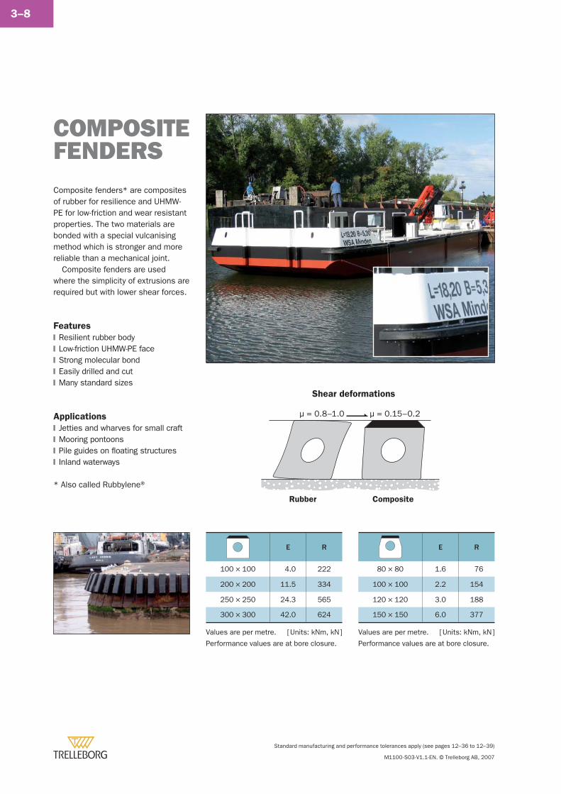
Standard manufacturing and performance tolerances apply (see pages 12–36 to 12–39)
M1100-S03-V1.1-EN. © Trelleborg AB, 2007
3–8
Composite fenders* are composites of rubber for resilience and UHMW-PE for low-friction and wear resistant properties. The two materials are bonded with a special vulcanising method which is stronger and more reliable than a mechanical joint.
Composite fenders are used where the simplicity of extrusions are required but with lower shear forces.
Features
Resilient rubber bodyLow-friction UHMW-PE faceStrong molecular bondEasily drilled and cutMany standard sizes
Applications
Jetties and wharves for small craftMooring pontoonsPile guides on fl oating structuresInland waterways
* Also called Rubbylene®
�
�
�
�
�
�
�
�
�
COMPOSITEFENDERS
E R
100 × 100 4.0 222
200 × 200 11.5 334
250 × 250 24.3 565
300 × 300 42.0 624
Values are per metre.
Performance values are at bore closure.
μ = 0.8–1.0
Rubber Composite
μ = 0.15–0.2
Shear deformations
E R
80 × 80 1.6 76
100 × 100 2.2 154
120 × 120 3.0 188
150 × 150 6.0 377
[ Units: kNm, kN ] [ Units: kNm, kN ]Values are per metre.
Performance values are at bore closure.
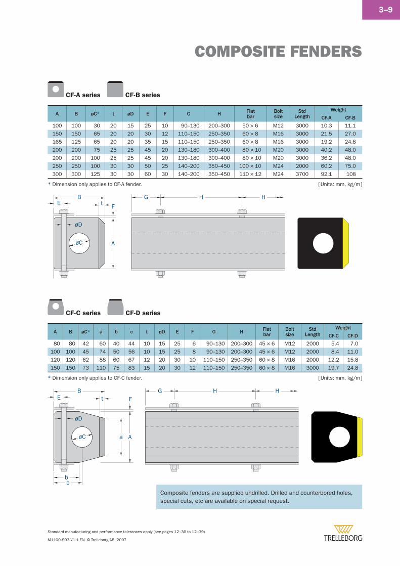
COMPOSITE FENDERS
Standard manufacturing and performance tolerances apply (see pages 12–36 to 12–39)
M1100-S03-V1.1-EN. © Trelleborg AB, 2007
3–9
CF-A series CF-B series
A B øC* t øD E F G H Flatbar
Boltsize
StdLength
Weight
CF-A CF-B
100 100 30 20 15 25 10 90–130 200–300 50 × 6 M12 3000 10.3 11.1
150 150 65 20 20 30 12 110–150 250–350 60 × 8 M16 3000 21.5 27.0
165 125 65 20 20 35 15 110–150 250–350 60 × 8 M16 3000 19.2 24.8
200 200 75 25 25 45 20 130–180 300–400 80 × 10 M20 3000 40.2 48.0
200 200 100 25 25 45 20 130–180 300–400 80 × 10 M20 3000 36.2 48.0
250 250 100 30 30 50 25 140–200 350–450 100 × 10 M24 2000 60.2 75.0
300 300 125 30 30 60 30 140–200 350–450 110 × 12 M24 3700 92.1 108
CF-C series CF-D series
A B øC* a b c t øD E F G H Flatbar
Boltsize
StdLength
Weight
CF-C CF-D
80 80 42 60 40 44 10 15 25 6 90–130 200–300 45 × 6 M12 2000 5.4 7.0
100 100 45 74 50 56 10 15 25 8 90–130 200–300 45 × 6 M12 2000 8.4 11.0
120 120 62 88 60 67 12 20 30 10 110–150 250–350 60 × 8 M16 2000 12.2 15.8
150 150 73 110 75 83 15 20 30 12 110–150 250–350 60 × 8 M16 3000 19.7 24.8
G H H
F
A
t
øC
BE
øD
G H HBE
øD
øC
F
Aa
b
t
c
[ Units: mm, kg/m ]* Dimension only applies to CF-C fender.
[ Units: mm, kg/m ]* Dimension only applies to CF-A fender.
Composite fenders are supplied undrilled. Drilled and counterbored holes, Composite fenders are supplied undrilled. Drilled and counterbored holes, special cuts, etc are available on special request.special cuts, etc are available on special request.
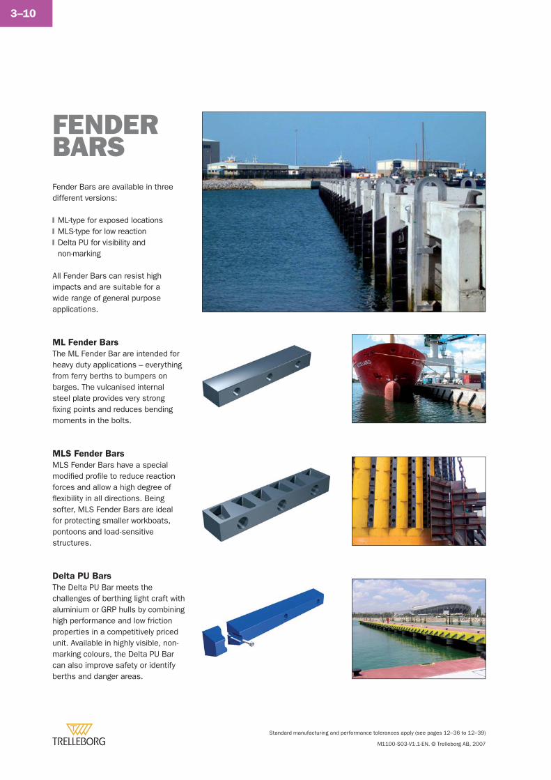
Standard manufacturing and performance tolerances apply (see pages 12–36 to 12–39)
M1100-S03-V1.1-EN. © Trelleborg AB, 2007
3–10
Fender Bars are available in three different versions:
ML-type for exposed locationsMLS-type for low reactionDelta PU for visibility and non-marking
All Fender Bars can resist high impacts and are suitable for a wide range of general purpose applications.
�
�
�
FENDER BARS
ML Fender Bars
The ML Fender Bar are intended for heavy duty applications – everything from ferry berths to bumpers on barges. The vulcanised internal steel plate provides very strong fi xing points and reduces bending moments in the bolts.
MLS Fender Bars
MLS Fender Bars have a special modifi ed profi le to reduce reaction forces and allow a high degree of fl exibility in all directions. Being softer, MLS Fender Bars are ideal for protecting smaller workboats, pontoons and load-sensitive structures.
Delta PU Bars
The Delta PU Bar meets the challenges of berthing light craft with aluminium or GRP hulls by combining high performance and low friction properties in a competitively priced unit. Available in highly visible, non-marking colours, the Delta PU Bar can also improve safety or identify berths and danger areas.
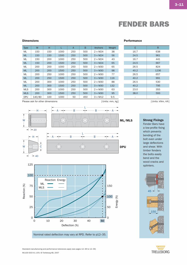
FENDER BARS
Standard manufacturing and performance tolerances apply (see pages 12–36 to 12–39)
M1100-S03-V1.1-EN. © Trelleborg AB, 2007
3–11
Strong Fixings
Fender Bars have a low-profi le fi xing which prevents bending of the bolt even under large defl ections and shear. With timber fenders the bolts easily bend and the wood cracks and splinters.
Type W H L A B Anchors Weight
ML 150 150 1000 250 500 2 × M24 38
ML 150 150 1500 250 500 3 × M24 56
ML 150 200 1000 250 500 2 × M24 43
ML 150 200 1500 250 500 3 × M24 65
ML 200 200 1000 250 500 2 × M30 65
ML 200 200 1500 250 500 3 × M30 98
ML 200 250 1000 250 500 2 × M30 77
ML 200 250 1500 250 500 3 × M30 116
ML 200 300 1000 250 500 2 × M30 88
ML 200 300 1500 250 500 3 × M30 132
MLS 200 300 1000 250 500 2 × M30 63
MLS 200 300 1500 250 500 3 × M30 95
DPU 140/80 100 1000 50 450 3 × M12 9.5
E R
16.7 638
24.5 961
16.7 441
24.5 667
26.5 824
40.2 1236
26.5 657
40.2 991
26.5 530
40.2 795
23.0 355
38.0 593
-- --
[ Units: mm, kg ]Please ask for other dimensions [ Units: kNm, kN ]
H
H
A B B A
W
W C
20
40
L
A B B AL
45
150
Dimensions Performance
Deflection (%)
Rea
ctio
n (%
)
100
0
25
50
75
125
0 10 20 30 40 50
MLMLS
EnergyReaction
Ener
gy (%
)100
0
50
150
ML/MLS
DPU
Nominal rated defl ection may vary at RPD. Refer to p12–35.Nominal rated defl ection may vary at RPD. Refer to p12–35.
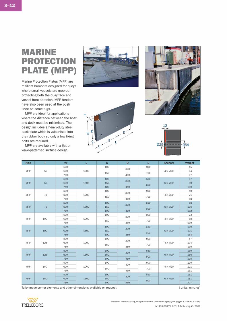
Standard manufacturing and performance tolerances apply (see pages 12–36 to 12–39)
M1100-S03-V1.1-EN. © Trelleborg AB, 2007
3–12
MARINEPROTECTION PLATE (MPP)Marine Protection Plates (MPP) are resilient bumpers designed for quays where small vessels are moored, protecting both the quay face and vessel from abrasion. MPP fenders have also been used at the push knee on some tugs.
MPP are ideal for applications where the distance between the boat and dock must be minimised. The design includes a heavy-duty steel back plate which is vulcanised into the rubber body so only a few fi xing bolts are required.
MPP are available with a fl at or wave-patterned surface design.
Type T W L C D E Anchors Weight
MPP 50
500
1000
100300
800
4 × M20
45
600150 700
54
750 450 67
MPP 50
500
1500
100300
650
6 × M20
67
600 150600
80
750 100 450 100
MPP 75
500
1000
100300
800
4 × M20
59
600150 700
71
750 450 88
MPP 75
500
1500
100300
650
6 × M20
88
600 150600
106
750 100 450 132
MPP 100
500
1000
100300
800
4 × M20
73
600150 700
88
750 450 109
MPP 100
500
1500
100300
650
6 × M20
109
600 150600
131
750 100 450 164
MPP 125
500
1000
100300
800
4 × M20
87
600150 700
104
750 450 130
MPP 125
500
1500
100300
650
6 × M20
130
600 150600
156
750 100 450 195
MPP 150
500
1000
100300
800
4 × M20
100
600150 700
121
750 450 151
MPP 150
500
1500
100300
650
6 × M20
151
600 150600
181
750 100 450 227
Tailor-made corner elements and other dimensions available on request. [ Units: mm, kg ]
W
C
D
E
E
C
T
LØ25
12
Ø54
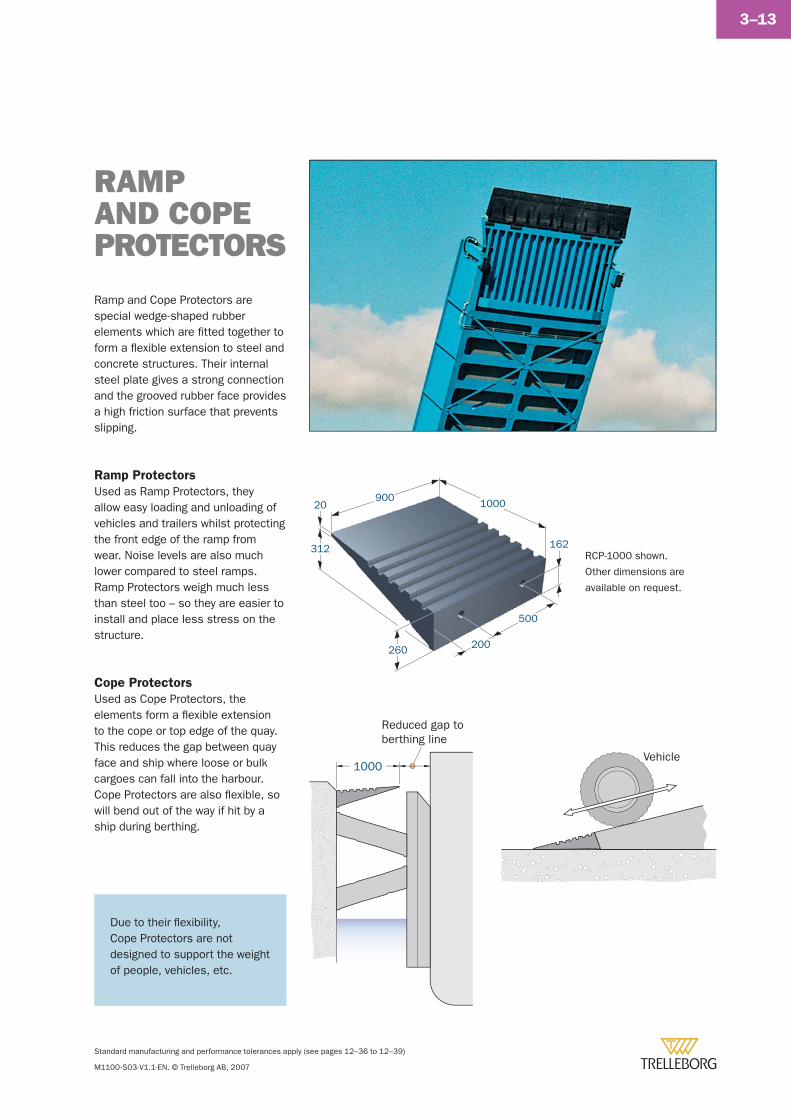
Standard manufacturing and performance tolerances apply (see pages 12–36 to 12–39)
M1100-S03-V1.1-EN. © Trelleborg AB, 2007
3–13
RAMP AND COPE PROTECTORS
Ramp and Cope Protectors are special wedge-shaped rubber elements which are fi tted together to form a fl exible extension to steel and concrete structures. Their internal steel plate gives a strong connection and the grooved rubber face provides a high friction surface that prevents slipping.
Ramp Protectors
Used as Ramp Protectors, they allow easy loading and unloading of vehicles and trailers whilst protecting the front edge of the ramp from wear. Noise levels are also much lower compared to steel ramps. Ramp Protectors weigh much less than steel too – so they are easier to install and place less stress on the structure.
Cope Protectors
Used as Cope Protectors, the elements form a fl exible extension to the cope or top edge of the quay. This reduces the gap between quay face and ship where loose or bulk cargoes can fall into the harbour. Cope Protectors are also fl exible, so will bend out of the way if hit by a ship during berthing.
260 200
500
100090020
162312RCP-1000 shown.
Other dimensions are
available on request.
1000
Reduced gap toberthing line
Vehicle
Due to their fl exibility, Cope Protectors are not designed to support the weight of people, vehicles, etc.
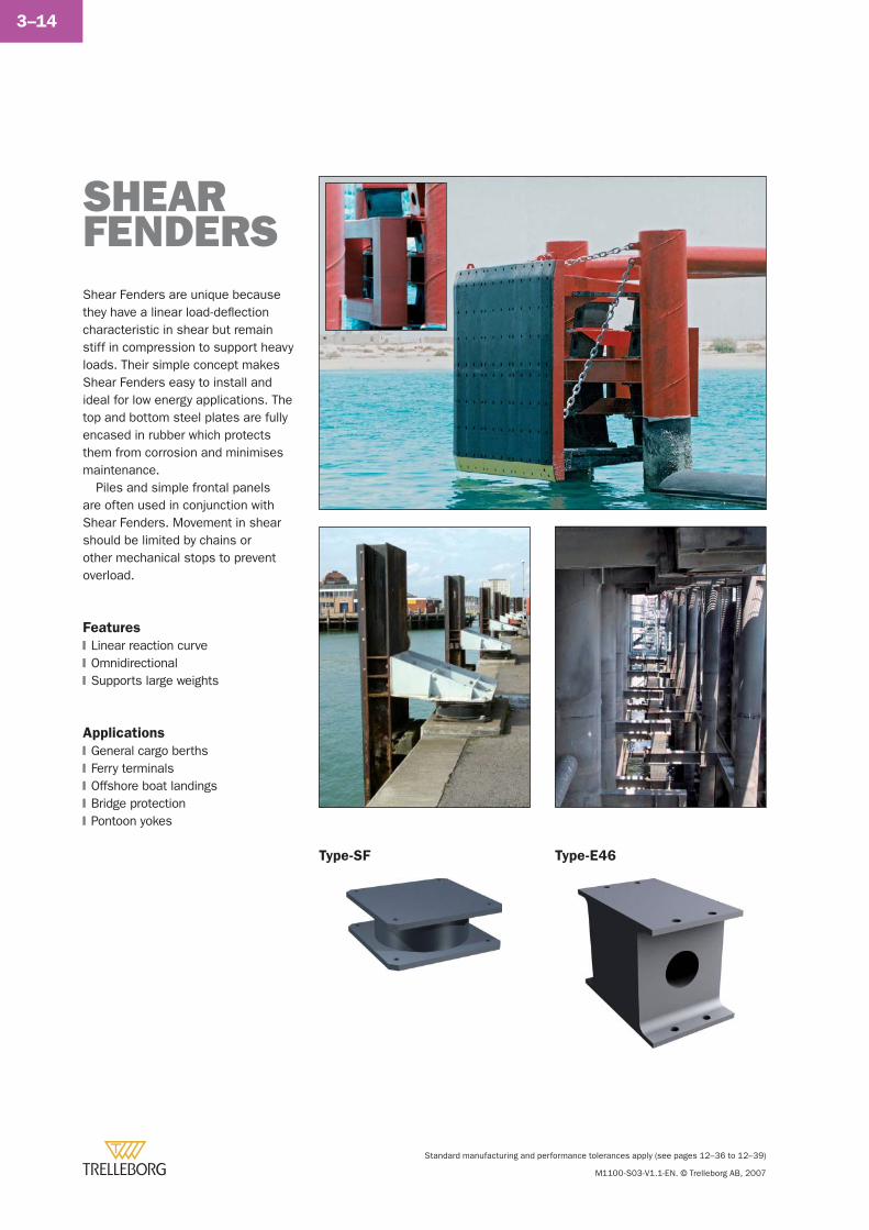
Standard manufacturing and performance tolerances apply (see pages 12–36 to 12–39)
M1100-S03-V1.1-EN. © Trelleborg AB, 2007
3–14
SHEAR FENDERSShear Fenders are unique because they have a linear load-defl ection characteristic in shear but remain stiff in compression to support heavy loads. Their simple concept makes Shear Fenders easy to install and ideal for low energy applications. The top and bottom steel plates are fully encased in rubber which protects them from corrosion and minimises maintenance.
Piles and simple frontal panels are often used in conjunction with Shear Fenders. Movement in shear should be limited by chains or other mechanical stops to prevent overload.
Features
Linear reaction curveOmnidirectionalSupports large weights
Applications
General cargo berthsFerry terminalsOffshore boat landingsBridge protectionPontoon yokes
�
�
�
�
�
�
�
�
Type-SF Type-E46
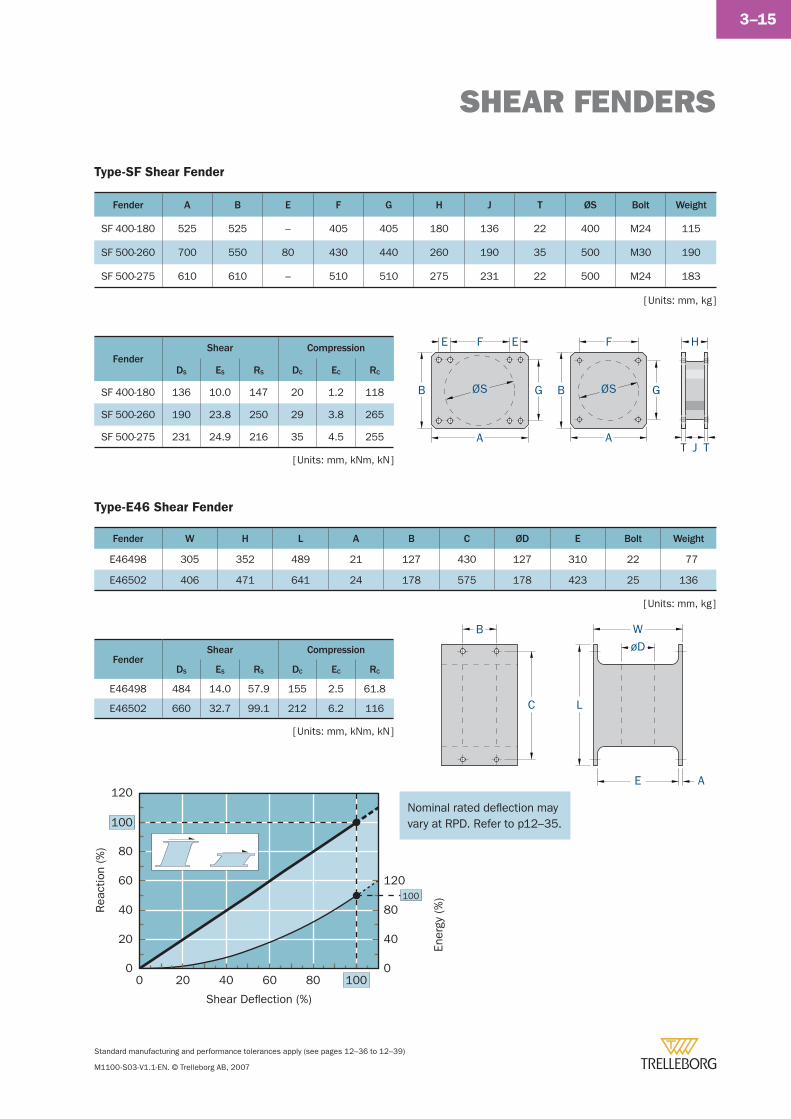
SHEAR FENDERS
Standard manufacturing and performance tolerances apply (see pages 12–36 to 12–39)
M1100-S03-V1.1-EN. © Trelleborg AB, 2007
3–15
[ Units: mm, kg ]
FenderShear Compression
DS ES RS DC EC RC
SF 400-180 136 10.0 147 20 1.2 118
SF 500-260 190 23.8 250 29 3.8 265
SF 500-275 231 24.9 216 35 4.5 255
Fender A B E F G H J T ØS Bolt Weight
SF 400-180 525 525 – 405 405 180 136 22 400 M24 115
SF 500-260 700 550 80 430 440 260 190 35 500 M30 190
SF 500-275 610 610 – 510 510 275 231 22 500 M24 183
[ Units: mm, kg ]
[ Units: mm, kNm, kN ]
[ Units: mm, kNm, kN ]
Type-SF Shear Fender
Type-E46 Shear Fender
H
J TTA
B ØS
E F E
G
A
B
F
GØS
Fender W H L A B C ØD E Bolt Weight
E46498 305 352 489 21 127 430 127 310 22 77
E46502 406 471 641 24 178 575 178 423 25 136
FenderShear Compression
DS ES RS DC EC RC
E46498 484 14.0 57.9 155 2.5 61.8
E46502 660 32.7 99.1 212 6.2 116 L
W
E A
øDB
C
0 20 40 60 80 100
Rea
ctio
n (%
)
100
0
20
40
60
80
Shear Deflection (%)
120
Ener
gy (%
)100
0
40
80
120
Nominal rated defl ection may Nominal rated defl ection may vary at RPD. Refer to p12–35.vary at RPD. Refer to p12–35.

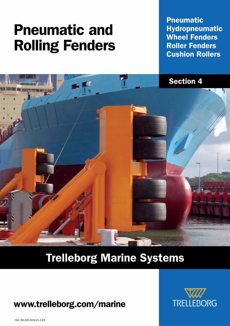
PneumaticHydropneumaticWheel FendersRoller FendersCushion Rollers
Pneumatic andRolling Fenders
Ref. M1100-S04-V1.1-EN
Section 4
www.trelleborg.com/marine
Trelleborg Marine Systems
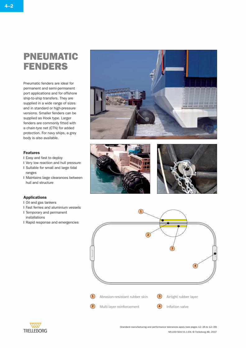
Standard manufacturing and performance tolerances apply (see pages 12–36 to 12–39)
M1100-S04-V1.1-EN. © Trelleborg AB, 2007
4–2
Pneumatic fenders are ideal for permanent and semi-permanent port applications and for offshore ship-to-ship transfers. They are supplied in a wide range of sizes and in standard or high-pressure versions. Smaller fenders can be supplied as Hook type. Larger fenders are commonly fi tted with a chain-tyre net (CTN) for added protection. For navy ships, a grey body is also available.
Features
Easy and fast to deployVery low reaction and hull pressureSuitable for small and large tidal rangesMaintains large clearances between hull and structure
Applications
Oil and gas tankersFast ferries and aluminium vesselsTemporary and permanent installationsRapid response and emergencies
�
�
�
�
�
�
�
�
PNEUMATIC FENDERS
1
2
3
4
Airtight rubber layer
Infl ation valve
3
4
Abrasion-resistant rubber skin
Multi-layer reinforcement
1
2
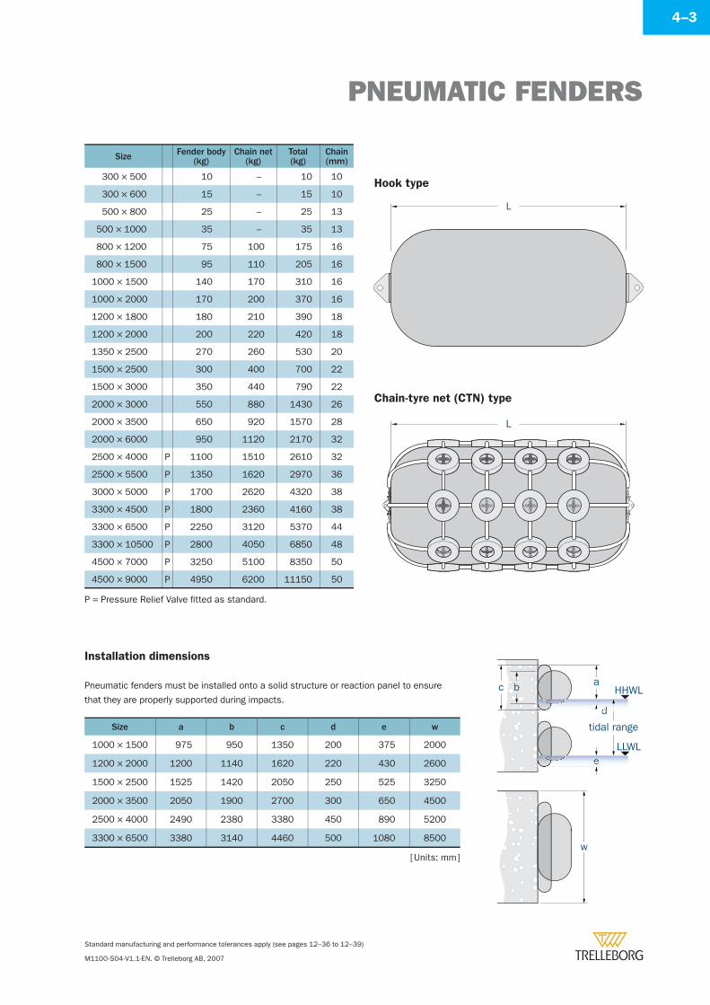
PNEUMATIC FENDERS
Standard manufacturing and performance tolerances apply (see pages 12–36 to 12–39)
M1100-S04-V1.1-EN. © Trelleborg AB, 2007
4–3
Size Fender body(kg)
Chain net(kg)
Total(kg)
Chain(mm)
300 × 500 10 – 10 10
300 × 600 15 – 15 10
500 × 800 25 – 25 13
500 × 1000 35 – 35 13
800 × 1200 75 100 175 16
800 × 1500 95 110 205 16
1000 × 1500 140 170 310 16
1000 × 2000 170 200 370 16
1200 × 1800 180 210 390 18
1200 × 2000 200 220 420 18
1350 × 2500 270 260 530 20
1500 × 2500 300 400 700 22
1500 × 3000 350 440 790 22
2000 × 3000 550 880 1430 26
2000 × 3500 650 920 1570 28
2000 × 6000 950 1120 2170 32
2500 × 4000 P 1100 1510 2610 32
2500 × 5500 P 1350 1620 2970 36
3000 × 5000 P 1700 2620 4320 38
3300 × 4500 P 1800 2360 4160 38
3300 × 6500 P 2250 3120 5370 44
3300 × 10500 P 2800 4050 6850 48
4500 × 7000 P 3250 5100 8350 50
4500 × 9000 P 4950 6200 11150 50
Installation dimensions
Pneumatic fenders must be installed onto a solid structure or reaction panel to ensure
that they are properly supported during impacts.
Size a b c d e w
1000 × 1500 975 950 1350 200 375 2000
1200 × 2000 1200 1140 1620 220 430 2600
1500 × 2500 1525 1420 2050 250 525 3250
2000 × 3500 2050 1900 2700 300 650 4500
2500 × 4000 2490 2380 3380 450 890 5200
3300 × 6500 3380 3140 4460 500 1080 8500
HHWL
LLWL
c b a
d
tidal range
e
w
P = Pressure Relief Valve fi tted as standard.
[ Units: mm ]
L
L
Hook type
Chain-tyre net (CTN) type
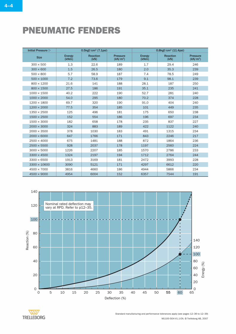
PNEUMATIC FENDERS
Standard manufacturing and performance tolerances apply (see pages 12–36 to 12–39)
M1100-S04-V1.1-EN. © Trelleborg AB, 2007
4–4
Initial Pressure 0.5kgf/cm2 (7.1psi) 0.8kgf/cm2 (11.4psi)
Size Energy(kNm)
Reaction(kN)
Pressure(kN/m2)
Energy(kNm)
Reaction(kN)
Pressure(kN/m2)
300 × 500 1.3 22.6 189 1.7 29.4 246
300 × 600 1.5 26.5 180 2.0 35.3 239
500 × 800 5.7 58.9 187 7.4 78.5 249
500 × 1000 7.2 73.6 179 9.1 98.1 239
800 × 1200 21.6 141 188 28.1 187 250
800 × 1500 27.5 186 191 35.1 235 241
1000 × 1500 40.2 222 190 52.7 281 240
1000 × 2000 54.0 295 180 70.2 374 228
1200 × 1800 69.7 320 190 91.0 404 240
1200 × 2000 77.5 354 185 101 449 235
1350 × 2500 125 496 181 175 650 238
1500 × 2500 152 554 186 196 697 234
1500 × 3000 182 658 178 235 837 227
2000 × 3000 324 883 189 422 1122 240
2000 × 3500 378 1030 183 491 1315 234
2000 × 6000 647 1766 171 843 2246 217
2500 × 4000 675 1481 188 872 1864 236
2500 × 5500 928 2037 178 1197 2560 224
3000 × 5000 1226 2207 185 1570 2786 233
3300 × 4500 1324 2197 194 1712 2764 244
3300 × 6500 1913 3169 181 2472 3993 228
3300 × 10600 3090 5121 171 4297 6612 220
4500 × 7000 3816 4660 186 4944 5866 234
4500 × 9000 4954 6004 152 6357 7544 191
55
Rea
ctio
n (%
)
Ener
gy (%
)
Deflection (%)
0
20
40
60
80
100
120
140
0 5 10 15 20 25 30 35 40 45 50 55 60 650
40
20
60
80
100
120
140
Nominal rated deflection mayvary at RPD. Refer to p12–35.
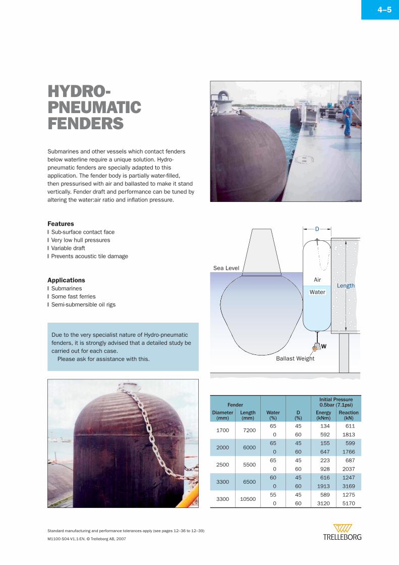
Standard manufacturing and performance tolerances apply (see pages 12–36 to 12–39)
M1100-S04-V1.1-EN. © Trelleborg AB, 2007
4–5
Fender
Water(%)
D(%)
Initial Pressure0.5bar (7.1psi)
Diameter(mm)
Length(mm)
Energy(kNm)
Reaction(kN)
1700 720065 45 134 611
0 60 592 1813
2000 600065 45 155 599
0 60 647 1766
2500 550065 45 223 687
0 60 928 2037
3300 650060 45 616 1247
0 60 1913 3169
3300 1050055 45 589 1275
0 60 3120 5170
HYDRO-PNEUMATIC FENDERSSubmarines and other vessels which contact fenders below waterline require a unique solution. Hydro-pneumatic fenders are specially adapted to this application. The fender body is partially water-fi lled, then pressurised with air and ballasted to make it stand vertically. Fender draft and performance can be tuned by altering the water:air ratio and infl ation pressure.
Features
Sub-surface contact faceVery low hull pressuresVariable draftPrevents acoustic tile damage
Applications
SubmarinesSome fast ferriesSemi-submersible oil rigs
�
�
�
�
�
�
�
Sea Level
Length
Ballast Weight
D
Air
Water
W
Due to the very specialist nature of Hydro-pneumatic fenders, it is strongly advised that a detailed study be carried out for each case.
Please ask for assistance with this.
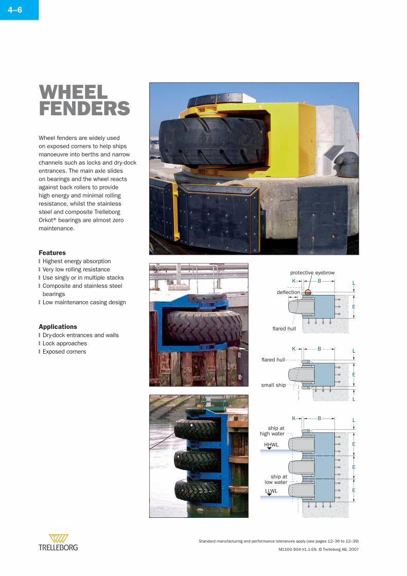
Standard manufacturing and performance tolerances apply (see pages 12–36 to 12–39)
M1100-S04-V1.1-EN. © Trelleborg AB, 2007
4–6
Wheel fenders are widely used on exposed corners to help ships manoeuvre into berths and narrow channels such as locks and dry-dock entrances. The main axle slides on bearings and the wheel reacts against back rollers to provide high energy and minimal rolling resistance, whilst the stainless steel and composite Trelleborg Orkot® bearings are almost zero maintenance.
Features
Highest energy absorptionVery low rolling resistanceUse singly or in multiple stacksComposite and stainless steel bearingsLow maintenance casing design
Applications
Dry-dock entrances and wallsLock approachesExposed corners
�
�
�
�
�
�
�
�
WHEELFENDERS
flared hull
small ship
L
E
L
K B
L
E
ship athigh water
ship atlow water
K B
E
E
flared hull
deflection
L
E
K B
protective eyebrow
HHWL
LLWL
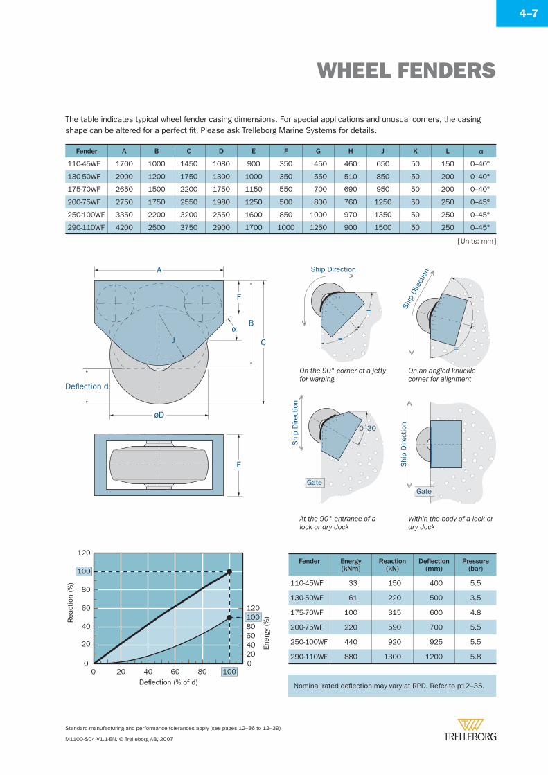
WHEEL FENDERS
Standard manufacturing and performance tolerances apply (see pages 12–36 to 12–39)
M1100-S04-V1.1-EN. © Trelleborg AB, 2007
4–7
The table indicates typical wheel fender casing dimensions. For special applications and unusual corners, the casing shape can be altered for a perfect fi t. Please ask Trelleborg Marine Systems for details.
Fender A B C D E F G H J K L α
110-45WF 1700 1000 1450 1080 900 350 450 460 650 50 150 0–40°
130-50WF 2000 1200 1750 1300 1000 350 550 510 850 50 200 0–40°
175-70WF 2650 1500 2200 1750 1150 550 700 690 950 50 200 0–40°
200-75WF 2750 1750 2550 1980 1250 500 800 760 1250 50 250 0–45°
250-100WF 3350 2200 3200 2550 1600 850 1000 970 1350 50 250 0–45°
290-110WF 4200 2500 3750 2900 1700 1000 1250 900 1500 50 250 0–45°
[ Units: mm ]
A
J
F
B
C
øD
α
Deflection d
E
Fender Energy(kNm)
Reaction(kN)
Defl ection(mm)
Pressure(bar)
110-45WF 33 150 400 5.5
130-50WF 61 220 500 3.5
175-70WF 100 315 600 4.8
200-75WF 220 590 700 5.5
250-100WF 440 920 925 5.5
290-110WF 880 1300 1200 5.8
Rea
ctio
n (%
)
Ener
gy (%
)
Deflection (% of d)
0
20
40
60
80
100
120
0 20 40 60 80 1000
4020
6080100120
Ship Direction
=
= Ship
Dire
ctio
n
=
=
0–30
Shi
p D
irect
ion
Gate
Shi
p D
irect
ion
Gate
On the 90° corner of a jetty for warping
On an angled knuckle corner for alignment
At the 90° entrance of a lock or dry dock
Within the body of a lock or dry dock
Nominal rated defl ection may vary at RPD. Refer to p12–35.Nominal rated defl ection may vary at RPD. Refer to p12–35.
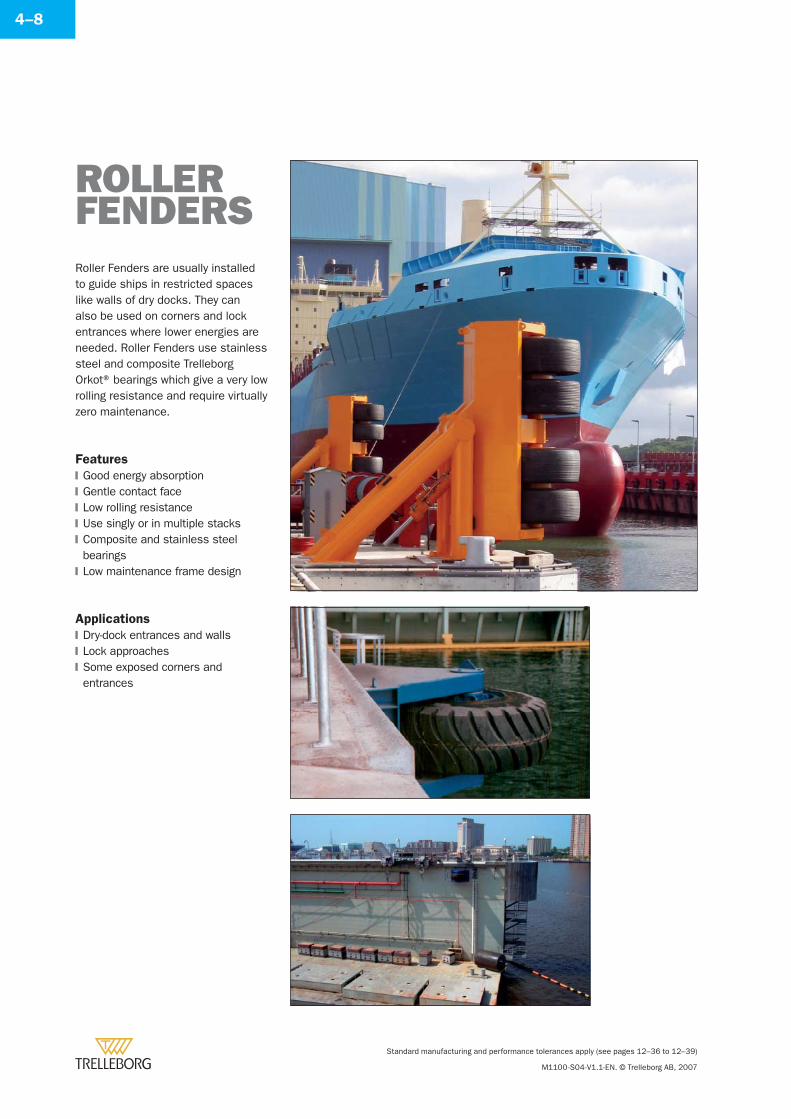
Standard manufacturing and performance tolerances apply (see pages 12–36 to 12–39)
M1100-S04-V1.1-EN. © Trelleborg AB, 2007
4–8
Roller Fenders are usually installed to guide ships in restricted spaces like walls of dry docks. They can also be used on corners and lock entrances where lower energies are needed. Roller Fenders use stainless steel and composite Trelleborg Orkot® bearings which give a very low rolling resistance and require virtually zero maintenance.
Features
Good energy absorptionGentle contact faceLow rolling resistanceUse singly or in multiple stacksComposite and stainless steel bearingsLow maintenance frame design
Applications
Dry-dock entrances and wallsLock approachesSome exposed corners and entrances
�
�
�
�
�
�
�
�
�
ROLLERFENDERS
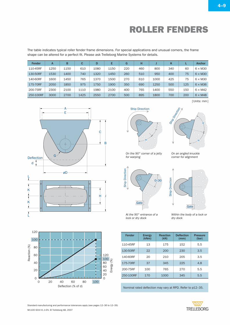
ROLLER FENDERS
Standard manufacturing and performance tolerances apply (see pages 12–36 to 12–39)
M1100-S04-V1.1-EN. © Trelleborg AB, 2007
4–9
The table indicates typical roller fender frame dimensions. For special applications and unusual corners, the frame shape can be altered for a perfect fi t. Please ask Trelleborg Marine Systems for details.
Fender A B C D E G H J K L Anchor
110-45RF 1250 1150 610 1080 1150 220 460 800 340 60 6 × M30
130-50RF 1530 1400 740 1320 1450 260 510 950 400 75 6 × M30
140-60RF 1600 1450 765 1370 1500 270 610 1000 425 75 6 × M30
175-70RF 2050 1850 975 1750 1900 350 690 1250 500 125 6 × M36
200-75RF 2300 2100 1110 1980 2100 400 765 1400 550 150 6 × M42
250-100RF 3000 2700 1425 2550 2700 500 895 1800 700 200 6 × M48
Fender Energy(kNm)
Reaction(kN)
Defl ection(mm)
Pressure(bar)
110-45RF 13 175 152 5.5
130-50RF 22 200 230 3.5
140-60RF 20 210 205 3.5
175-70RF 37 345 225 4.8
200-75RF 100 765 270 5.5
250-100RF 170 1000 345 5.5
Rea
ctio
n (%
)
Ener
gy (%
)
Deflection (% of d)
0
20
40
60
80
100
120
0 20 40 60 80 1000
4020
6080100120
[ Units: mm ]
AE
C
B
øD
G
JH
L
K
L
d
Deflection
K
=
=
Ship
Dire
ctio
n
Shi
p D
irect
ion
0–30
Gate
Ship Direction
Shi
p D
irect
ion
=
=
Gate
On the 90° corner of a jetty for warping
On an angled knuckle corner for alignment
At the 90° entrance of a lock or dry dock
Within the body of a lock or dry dock
Nominal rated defl ection may vary at RPD. Refer to p12–35.Nominal rated defl ection may vary at RPD. Refer to p12–35.
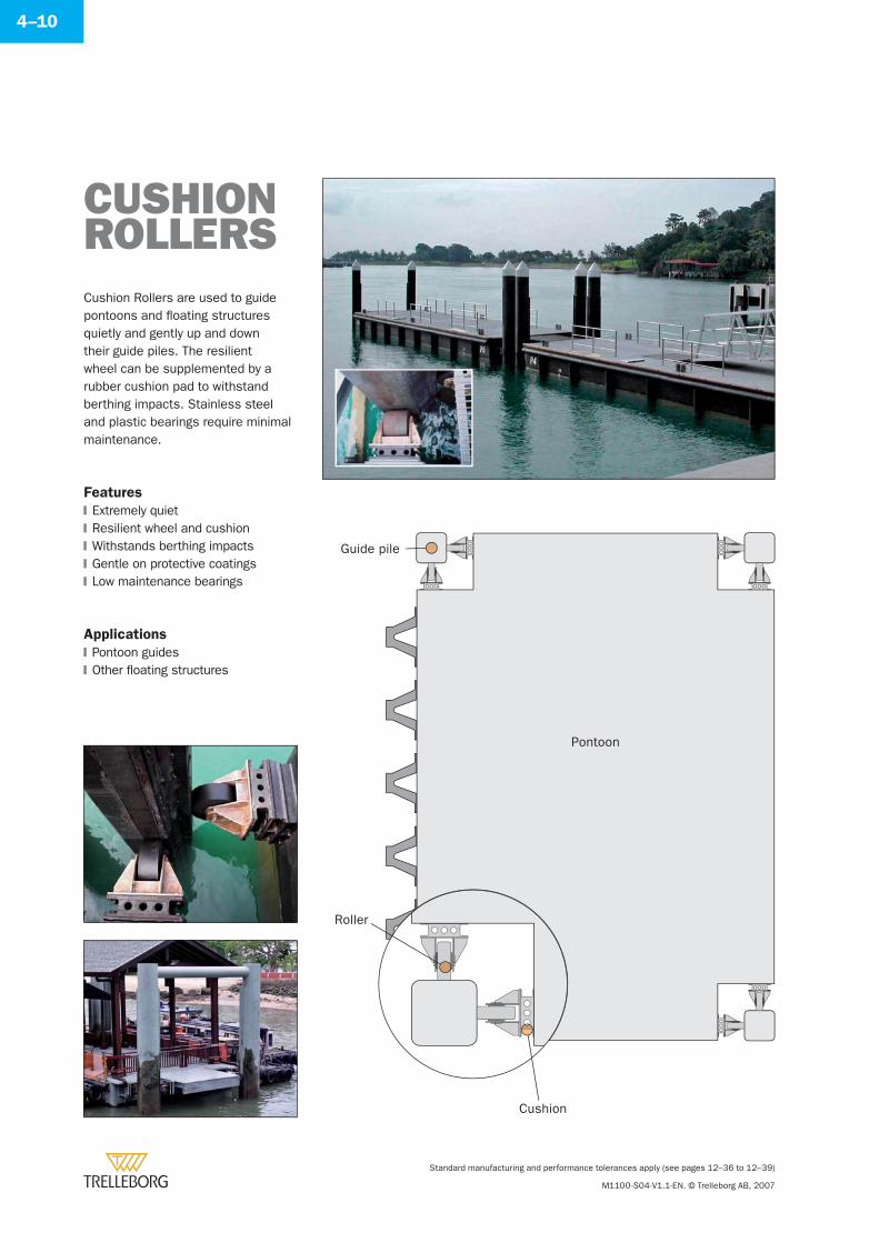
Standard manufacturing and performance tolerances apply (see pages 12–36 to 12–39)
M1100-S04-V1.1-EN. © Trelleborg AB, 2007
4–10
Cushion Rollers are used to guide pontoons and fl oating structures quietly and gently up and down their guide piles. The resilient wheel can be supplemented by a rubber cushion pad to withstand berthing impacts. Stainless steel and plastic bearings require minimal maintenance.
Features
Extremely quietResilient wheel and cushionWithstands berthing impactsGentle on protective coatingsLow maintenance bearings
Applications
Pontoon guidesOther fl oating structures
�
�
�
�
�
�
�
CUSHIONROLLERS
Cushion
Roller
Guide pile
Pontoon
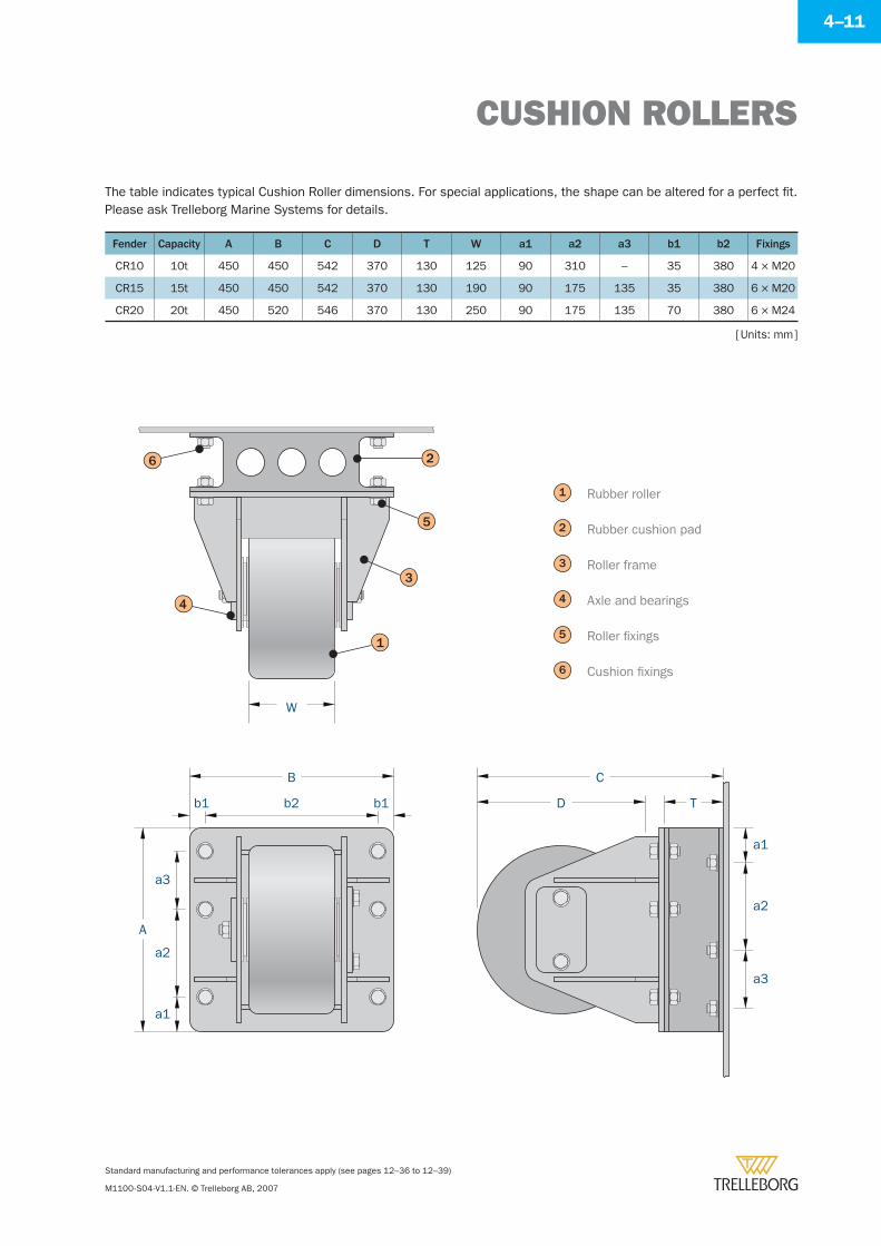
CUSHION ROLLERS
Standard manufacturing and performance tolerances apply (see pages 12–36 to 12–39)
M1100-S04-V1.1-EN. © Trelleborg AB, 2007
4–11
The table indicates typical Cushion Roller dimensions. For special applications, the shape can be altered for a perfect fi t. Please ask Trelleborg Marine Systems for details.
Fender Capacity A B C D T W a1 a2 a3 b1 b2 Fixings
CR10 10t 450 450 542 370 130 125 90 310 – 35 380 4 × M20
CR15 15t 450 450 542 370 130 190 90 175 135 35 380 6 × M20
CR20 20t 450 520 546 370 130 250 90 175 135 70 380 6 × M24
[ Units: mm ]
W
b1
a1
a2
a3
b1b2
B
A
C
D T
a1
a2
a3
5
3
1
4
6 2
3
4
Rubber roller
Rubber cushion pad
Roller frame
Axle and bearings
Roller fi xings
Cushion fi xings
1
2
5
6

SeaGuardSeaCushionDonutSeaFloat
Foam Fendersand Buoys
Ref. M1100-S05-V1.1-EN
Section 5
www.trelleborg.com/marine
Trelleborg Marine Systems
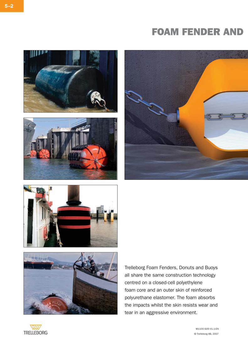
M1100-S05-V1.1-EN
© Trelleborg AB, 2007
FOAM FENDER AND
5–2
Trelleborg Foam Fenders, Donuts and Buoys
all share the same construction technology
centred on a closed-cell polyethylene
foam core and an outer skin of reinforced
polyurethane elastomer. The foam absorbs
the impacts whilst the skin resists wear and
tear in an aggressive environment.
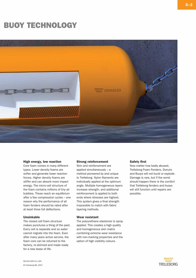
M1100-S05-V1.1-EN
© Trelleborg AB, 2007
BUOY TECHNOLOGY
5–3
High energy, low reaction
Core foam comes in many different types. Lower density foams are softer and generate lower reaction forces. Higher density foams are stiffer and can absorb more impact energy. The micro-cell structure of the foam contains millions of tiny air bubbles. These reach an equilibrium after a few compression cycles – one reason why the performance of all foam fenders should be rated after at least three full defl ections.
Unsinkable
The closed cell foam structure makes punctures a thing of the past. Every cell is separate and so water cannot migrate into the foam. Even after many years active service, the foam core can be returned to the factory, re-skinned and made ready for a new lease of life.
Strong reinforcement
Skin and reinforcement are applied simultaneously – a method pioneered by and unique to Trelleborg. Nylon fi laments are individually applied at the optimum angle. Multiple homogeneous layers increase strength, and additional reinforcement is applied to both ends where stresses are highest. This system gives a fi nal strength impossible to match with fabric layering methods.
Wear resistant
The polyurethane elastomer is spray applied. This creates a high quality and homogeneous skin matrix combining extreme wear resistance with non-marking properties and the option of high visibility colours.
Safety fi rst
Now matter how badly abused, Trelleborg Foam Fenders, Donuts and Buoys will not burst or explode. Damage is rare, but if the worst should happen there is the comfort that Trelleborg fenders and buoys will still function until repairs are possible.
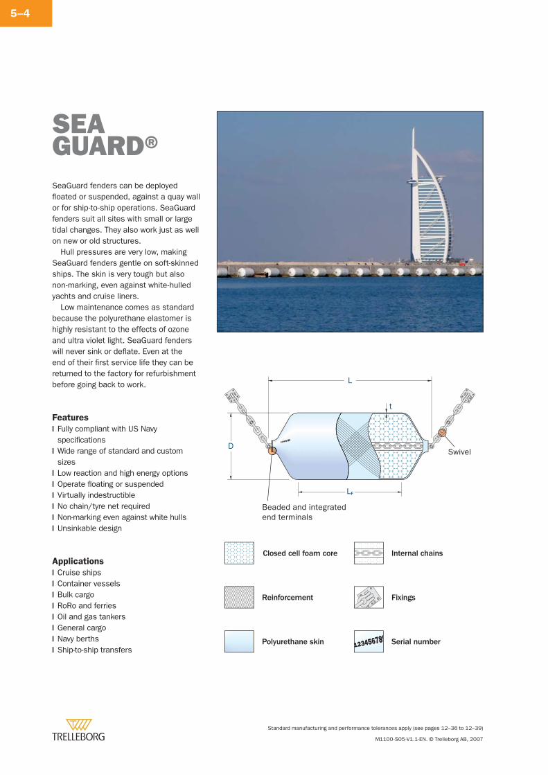
Standard manufacturing and performance tolerances apply (see pages 12–36 to 12–39)
M1100-S05-V1.1-EN. © Trelleborg AB, 2007
5–4
SeaGuard fenders can be deployed fl oated or suspended, against a quay wall or for ship-to-ship operations. SeaGuard fenders suit all sites with small or large tidal changes. They also work just as well on new or old structures.
Hull pressures are very low, making SeaGuard fenders gentle on soft-skinned ships. The skin is very tough but also non-marking, even against white-hulled yachts and cruise liners.
Low maintenance comes as standard because the polyurethane elastomer is highly resistant to the effects of ozone and ultra violet light. SeaGuard fenders will never sink or defl ate. Even at the end of their fi rst service life they can be returned to the factory for refurbishment before going back to work.
Features
Fully compliant with US Navy specifi cationsWide range of standard and custom sizesLow reaction and high energy optionsOperate fl oating or suspendedVirtually indestructibleNo chain/tyre net requiredNon-marking even against white hullsUnsinkable design
Applications
Cruise shipsContainer vesselsBulk cargoRoRo and ferriesOil and gas tankersGeneral cargoNavy berthsShip-to-ship transfers
�
�
�
�
�
�
�
�
�
�
�
�
�
�
�
�
SEAGUARD®
Internal chains
Fixings
Serial number
Closed cell foam core
Reinforcement
Polyurethane skin
L
t
LF
D
Beaded and integratedend terminals
Swivel
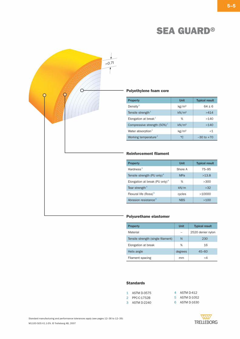
SEA GUARD®
Standard manufacturing and performance tolerances apply (see pages 12–36 to 12–39)
M1100-S05-V1.1-EN. © Trelleborg AB, 2007
5–5
Polyethylene foam core
Property Unit Typical result
Density 1 kg/m3 64 ± 6
Tensile strength 1 kN/m2 >414
Elongation at break 1 % >140
Compressive strength (50%) 1 kN/m2 >140
Water absorption 1 kg/m2 <1
Working temperature 2 ºC –30 to +70
Reinforcement fi lament
Property Unit Typical result
Hardness 3 Shore A 75–95
Tensile strength (PU only) 4 MPa >13.8
Elongation at break (PU only) 4 % >300
Tear strength 4 kN/m >32
Flexural life (Ross) 5 cycles >10000
Abrasion resistance 6 NBS >100
Polyurethane elastomer
Property Unit Typical result
Material – 2520 denier nylon
Tensile strength (single fi lament) N 230
Elongation at break % 16
Helix angle degrees 45–60
Filament spacing mm <4
Standards
1 ASTM D-3575
2 PPC-C-1752B
3 ASTM D-2240
4 ASTM D-412
5 ASTM D-1052
6 ASTM D-1630
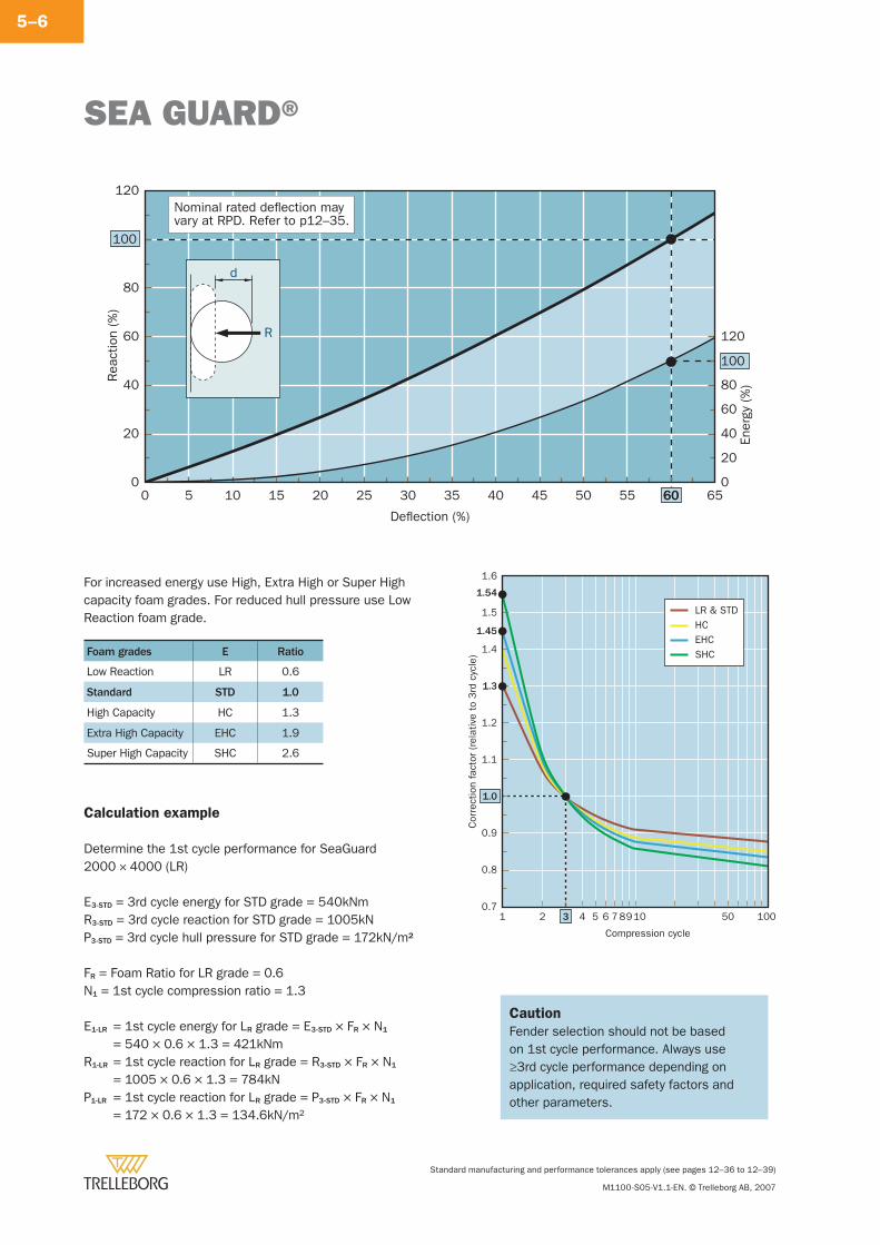
SEA GUARD®
Standard manufacturing and performance tolerances apply (see pages 12–36 to 12–39)
M1100-S05-V1.1-EN. © Trelleborg AB, 2007
5–6
Foam grades E Ratio
Low Reaction LR 0.6
Standard STD 1.0
High Capacity HC 1.3
Extra High Capacity EHC 1.9
Super High Capacity SHC 2.6
60
100
100
0 5 10 15 20 25 30 35 40 45 50 55 60 65
Rea
ctio
n (%
)
Ener
gy (
%)
Deflection (%)
0
20
40
60
80
120
0
20
40
60
80
120
d
R
Nominal rated deflection mayvary at RPD. Refer to p12–35.
Calculation example
Determine the 1st cycle performance for SeaGuard2000 × 4000 (LR)
E3-STD = 3rd cycle energy for STD grade = 540kNmR3-STD = 3rd cycle reaction for STD grade = 1005kNP3-STD = 3rd cycle hull pressure for STD grade = 172kN/m2
FR = Foam Ratio for LR grade = 0.6N1 = 1st cycle compression ratio = 1.3
E1-LR = 1st cycle energy for LR grade = E3-STD × FR × N1 = 540 × 0.6 × 1.3 = 421kNm
R1-LR = 1st cycle reaction for LR grade = R3-STD × FR × N1 = 1005 × 0.6 × 1.3 = 784kN
P1-LR = 1st cycle reaction for LR grade = P3-STD × FR × N1 = 172 × 0.6 × 1.3 = 134.6kN/m2
Caution
Fender selection should not be based on 1st cycle performance. Always use ≥3rd cycle performance depending on application, required safety factors and other parameters.
Compression cycle
Cor
rect
ion
fact
or (
rela
tive
to 3
rd c
ycle
)
1
0.8
0.7
0.9
1.1
1.2
1.3
1.4
1.45
1.5
1.54
1.6
2 4 5 6 78910 50 100
LR & STDHCEHCSHC
1.0
3
For increased energy use High, Extra High or Super High capacity foam grades. For reduced hull pressure use Low Reaction foam grade.
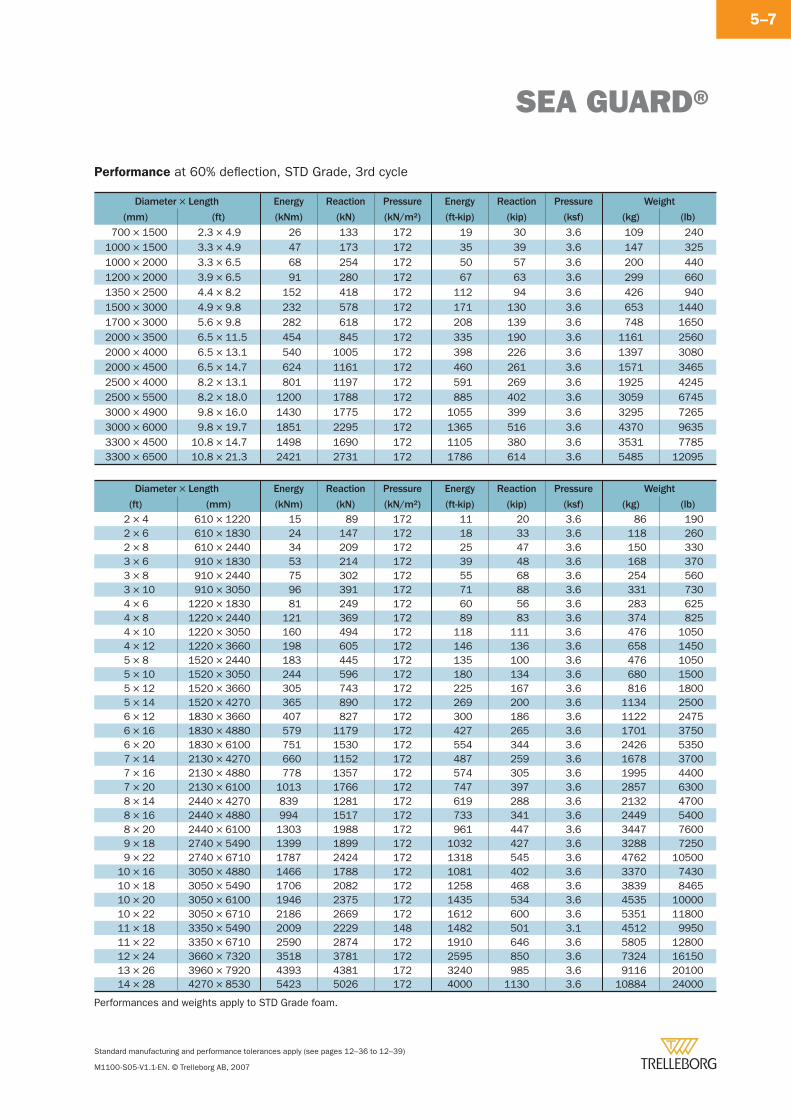
SEA GUARD®
Standard manufacturing and performance tolerances apply (see pages 12–36 to 12–39)
M1100-S05-V1.1-EN. © Trelleborg AB, 2007
5–7
Performance at 60% defl ection, STD Grade, 3rd cycle
Diameter × Length Energy Reaction Pressure Energy Reaction Pressure Weight
(mm) (ft) (kNm) (kN) (kN/m2) (ft-kip) (kip) (ksf) (kg) (lb)
700 × 1500 2.3 × 4.9 26 133 172 19 30 3.6 109 2401000 × 1500 3.3 × 4.9 47 173 172 35 39 3.6 147 3251000 × 2000 3.3 × 6.5 68 254 172 50 57 3.6 200 4401200 × 2000 3.9 × 6.5 91 280 172 67 63 3.6 299 6601350 × 2500 4.4 × 8.2 152 418 172 112 94 3.6 426 9401500 × 3000 4.9 × 9.8 232 578 172 171 130 3.6 653 14401700 × 3000 5.6 × 9.8 282 618 172 208 139 3.6 748 16502000 × 3500 6.5 × 11.5 454 845 172 335 190 3.6 1161 25602000 × 4000 6.5 × 13.1 540 1005 172 398 226 3.6 1397 30802000 × 4500 6.5 × 14.7 624 1161 172 460 261 3.6 1571 34652500 × 4000 8.2 × 13.1 801 1197 172 591 269 3.6 1925 42452500 × 5500 8.2 × 18.0 1200 1788 172 885 402 3.6 3059 67453000 × 4900 9.8 × 16.0 1430 1775 172 1055 399 3.6 3295 72653000 × 6000 9.8 × 19.7 1851 2295 172 1365 516 3.6 4370 96353300 × 4500 10.8 × 14.7 1498 1690 172 1105 380 3.6 3531 77853300 × 6500 10.8 × 21.3 2421 2731 172 1786 614 3.6 5485 12095
Diameter × Length Energy Reaction Pressure Energy Reaction Pressure Weight
(ft) (mm) (kNm) (kN) (kN/m2) (ft-kip) (kip) (ksf) (kg) (lb)2 × 4 610 × 1220 15 89 172 11 20 3.6 86 1902 × 6 610 × 1830 24 147 172 18 33 3.6 118 2602 × 8 610 × 2440 34 209 172 25 47 3.6 150 3303 × 6 910 × 1830 53 214 172 39 48 3.6 168 3703 × 8 910 × 2440 75 302 172 55 68 3.6 254 5603 × 10 910 × 3050 96 391 172 71 88 3.6 331 7304 × 6 1220 × 1830 81 249 172 60 56 3.6 283 6254 × 8 1220 × 2440 121 369 172 89 83 3.6 374 8254 × 10 1220 × 3050 160 494 172 118 111 3.6 476 10504 × 12 1220 × 3660 198 605 172 146 136 3.6 658 14505 × 8 1520 × 2440 183 445 172 135 100 3.6 476 10505 × 10 1520 × 3050 244 596 172 180 134 3.6 680 15005 × 12 1520 × 3660 305 743 172 225 167 3.6 816 18005 × 14 1520 × 4270 365 890 172 269 200 3.6 1134 25006 × 12 1830 × 3660 407 827 172 300 186 3.6 1122 24756 × 16 1830 × 4880 579 1179 172 427 265 3.6 1701 37506 × 20 1830 × 6100 751 1530 172 554 344 3.6 2426 53507 × 14 2130 × 4270 660 1152 172 487 259 3.6 1678 37007 × 16 2130 × 4880 778 1357 172 574 305 3.6 1995 44007 × 20 2130 × 6100 1013 1766 172 747 397 3.6 2857 63008 × 14 2440 × 4270 839 1281 172 619 288 3.6 2132 47008 × 16 2440 × 4880 994 1517 172 733 341 3.6 2449 54008 × 20 2440 × 6100 1303 1988 172 961 447 3.6 3447 76009 × 18 2740 × 5490 1399 1899 172 1032 427 3.6 3288 72509 × 22 2740 × 6710 1787 2424 172 1318 545 3.6 4762 10500
10 × 16 3050 × 4880 1466 1788 172 1081 402 3.6 3370 743010 × 18 3050 × 5490 1706 2082 172 1258 468 3.6 3839 846510 × 20 3050 × 6100 1946 2375 172 1435 534 3.6 4535 1000010 × 22 3050 × 6710 2186 2669 172 1612 600 3.6 5351 1180011 × 18 3350 × 5490 2009 2229 148 1482 501 3.1 4512 995011 × 22 3350 × 6710 2590 2874 172 1910 646 3.6 5805 1280012 × 24 3660 × 7320 3518 3781 172 2595 850 3.6 7324 1615013 × 26 3960 × 7920 4393 4381 172 3240 985 3.6 9116 2010014 × 28 4270 × 8530 5423 5026 172 4000 1130 3.6 10884 24000
Performances and weights apply to STD Grade foam.
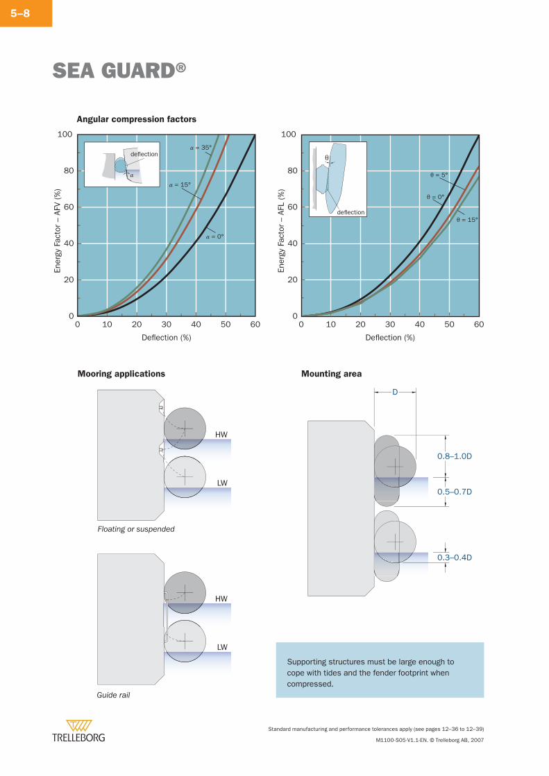
SEA GUARD®
Standard manufacturing and performance tolerances apply (see pages 12–36 to 12–39)
M1100-S05-V1.1-EN. © Trelleborg AB, 2007
5–8
Angular compression factors
100
0 10 20 30 40 50 60
Ener
gy F
acto
r –
AFL
(%)
Deflection (%)
0
20
40
60
80
θ = 0°
θ = 15°
θ = 5°
θ
deflection
Mooring applications
100
0 10 20 30 40 50 60
Ener
gy F
acto
r –
AFV
(%)
Deflection (%)
0
20
40
60
80
α = 0°
α = 15°
α = 35°deflection
α
Floating or suspended
HW
LW
Guide rail
HW
LW
Mounting area
D
0.8–1.0D
0.5–0.7D
0.3–0.4D
Supporting structures must be large enough to cope with tides and the fender footprint when compressed.
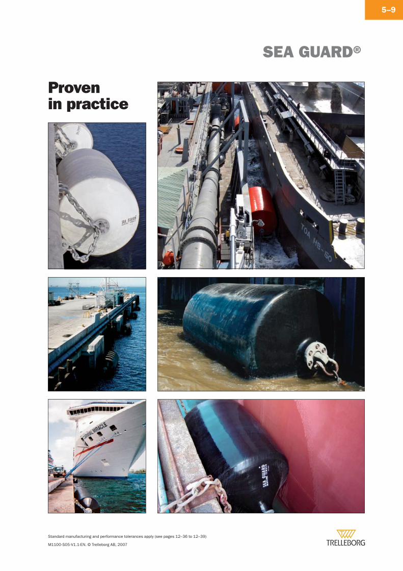
SEA GUARD®
Standard manufacturing and performance tolerances apply (see pages 12–36 to 12–39)
M1100-S05-V1.1-EN. © Trelleborg AB, 2007
5–9
Provenin practice
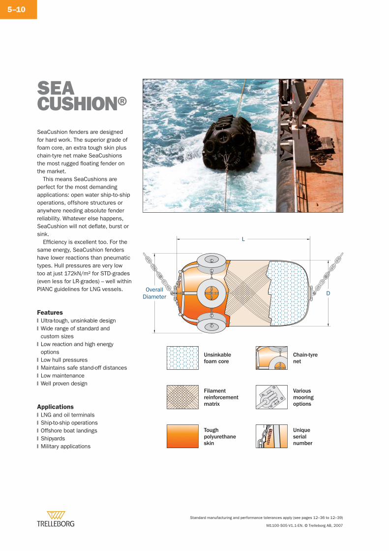
Standard manufacturing and performance tolerances apply (see pages 12–36 to 12–39)
M1100-S05-V1.1-EN. © Trelleborg AB, 2007
5–10
SeaCushion fenders are designed for hard work. The superior grade of foam core, an extra tough skin plus chain-tyre net make SeaCushions the most rugged fl oating fender on the market.
This means SeaCushions are perfect for the most demanding applications: open water ship-to-ship operations, offshore structures or anywhere needing absolute fender reliability. Whatever else happens, SeaCushion will not defl ate, burst or sink.
Effi ciency is excellent too. For the same energy, SeaCushion fenders have lower reactions than pneumatic types. Hull pressures are very low too at just 172kN/m2 for STD-grades (even less for LR-grades) – well within PIANC guidelines for LNG vessels.
Features
Ultra-tough, unsinkable designWide range of standard and custom sizesLow reaction and high energy optionsLow hull pressuresMaintains safe stand-off distancesLow maintenanceWell proven design
Applications
LNG and oil terminalsShip-to-ship operationsOffshore boat landingsShipyardsMilitary applications
�
�
�
�
�
�
�
�
�
�
�
�
SEACUSHION®
Chain-tyrenet
Variousmooringoptions
Uniqueserialnumber
Unsinkable foam core
Filament reinforcement matrix
Toughpolyurethaneskin
L
OverallDiameter D
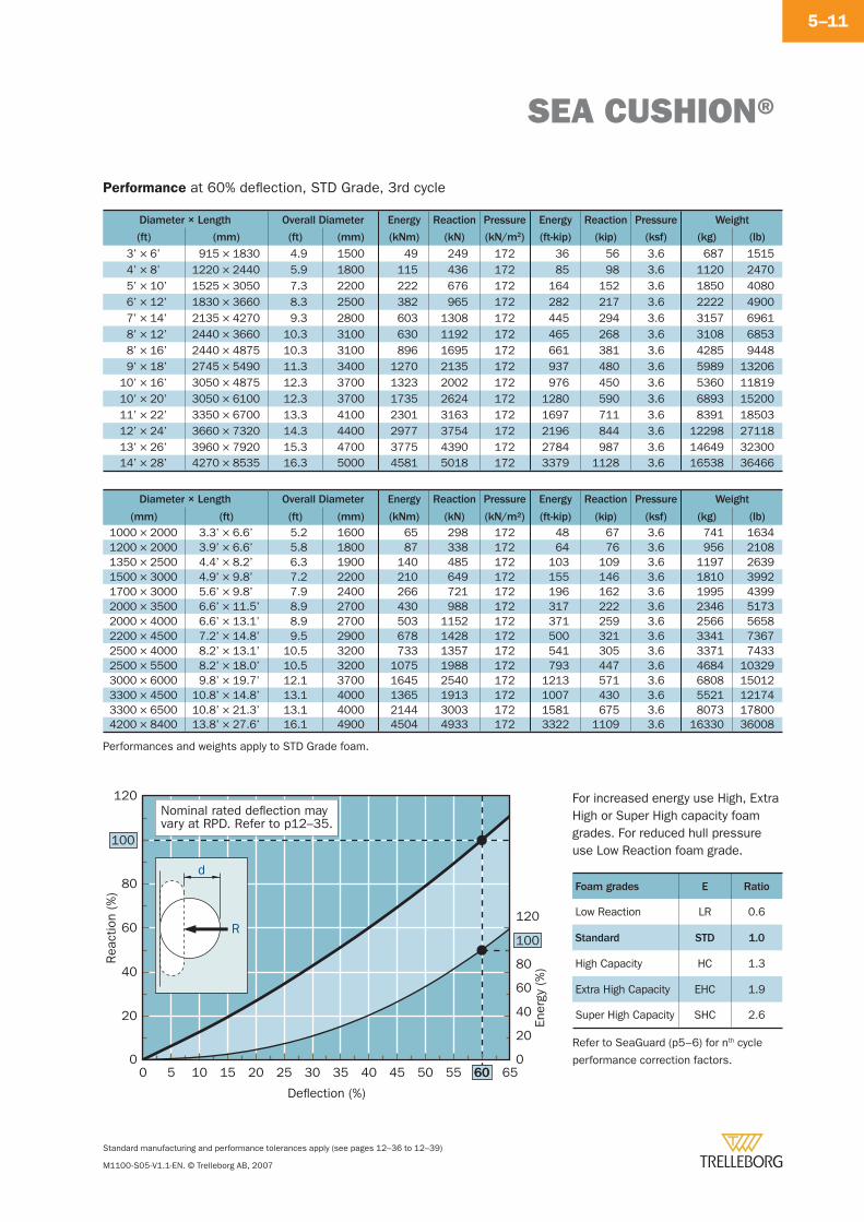
SEA CUSHION®
Standard manufacturing and performance tolerances apply (see pages 12–36 to 12–39)
M1100-S05-V1.1-EN. © Trelleborg AB, 2007
5–11
Diameter × Length Overall Diameter Energy Reaction Pressure Energy Reaction Pressure Weight
(ft) (mm) (ft) (mm) (kNm) (kN) (kN/m2) (ft-kip) (kip) (ksf) (kg) (lb)
3’ × 6’ 915 × 1830 4.9 1500 49 249 172 36 56 3.6 687 15154’ × 8’ 1220 × 2440 5.9 1800 115 436 172 85 98 3.6 1120 24705’ × 10’ 1525 × 3050 7.3 2200 222 676 172 164 152 3.6 1850 40806’ × 12’ 1830 × 3660 8.3 2500 382 965 172 282 217 3.6 2222 49007’ × 14’ 2135 × 4270 9.3 2800 603 1308 172 445 294 3.6 3157 69618’ × 12’ 2440 × 3660 10.3 3100 630 1192 172 465 268 3.6 3108 68538’ × 16’ 2440 × 4875 10.3 3100 896 1695 172 661 381 3.6 4285 94489’ × 18’ 2745 × 5490 11.3 3400 1270 2135 172 937 480 3.6 5989 13206
10’ × 16’ 3050 × 4875 12.3 3700 1323 2002 172 976 450 3.6 5360 1181910’ × 20’ 3050 × 6100 12.3 3700 1735 2624 172 1280 590 3.6 6893 1520011’ × 22’ 3350 × 6700 13.3 4100 2301 3163 172 1697 711 3.6 8391 1850312’ × 24’ 3660 × 7320 14.3 4400 2977 3754 172 2196 844 3.6 12298 2711813’ × 26’ 3960 × 7920 15.3 4700 3775 4390 172 2784 987 3.6 14649 3230014’ × 28’ 4270 × 8535 16.3 5000 4581 5018 172 3379 1128 3.6 16538 36466
Diameter × Length Overall Diameter Energy Reaction Pressure Energy Reaction Pressure Weight
(mm) (ft) (ft) (mm) (kNm) (kN) (kN/m2) (ft-kip) (kip) (ksf) (kg) (lb)1000 × 2000 3.3’ × 6.6’ 5.2 1600 65 298 172 48 67 3.6 741 16341200 × 2000 3.9’ × 6.6’ 5.8 1800 87 338 172 64 76 3.6 956 21081350 × 2500 4.4’ × 8.2’ 6.3 1900 140 485 172 103 109 3.6 1197 26391500 × 3000 4.9’ × 9.8’ 7.2 2200 210 649 172 155 146 3.6 1810 39921700 × 3000 5.6’ × 9.8’ 7.9 2400 266 721 172 196 162 3.6 1995 43992000 × 3500 6.6’ × 11.5’ 8.9 2700 430 988 172 317 222 3.6 2346 51732000 × 4000 6.6’ × 13.1’ 8.9 2700 503 1152 172 371 259 3.6 2566 56582200 × 4500 7.2’ × 14.8’ 9.5 2900 678 1428 172 500 321 3.6 3341 73672500 × 4000 8.2’ × 13.1’ 10.5 3200 733 1357 172 541 305 3.6 3371 74332500 × 5500 8.2’ × 18.0’ 10.5 3200 1075 1988 172 793 447 3.6 4684 103293000 × 6000 9.8’ × 19.7’ 12.1 3700 1645 2540 172 1213 571 3.6 6808 150123300 × 4500 10.8’ × 14.8’ 13.1 4000 1365 1913 172 1007 430 3.6 5521 121743300 × 6500 10.8’ × 21.3’ 13.1 4000 2144 3003 172 1581 675 3.6 8073 178004200 × 8400 13.8’ × 27.6’ 16.1 4900 4504 4933 172 3322 1109 3.6 16330 36008
Performance at 60% defl ection, STD Grade, 3rd cycle
100
100
0 5 10 15 20 25 30 35 40 45 50 55 6060 65
Rea
ctio
n (%
)
Ener
gy (%
)
Deflection (%)
0
20
40
60
80
120
0
20
40
60
80
120
d
R
Nominal rated deflection mayvary at RPD. Refer to p12–35.
Foam grades E Ratio
Low Reaction LR 0.6
Standard STD 1.0
High Capacity HC 1.3
Extra High Capacity EHC 1.9
Super High Capacity SHC 2.6
For increased energy use High, Extra High or Super High capacity foam grades. For reduced hull pressure use Low Reaction foam grade.
Refer to SeaGuard (p5–6) for nth cycle
performance correction factors.
Performances and weights apply to STD Grade foam.
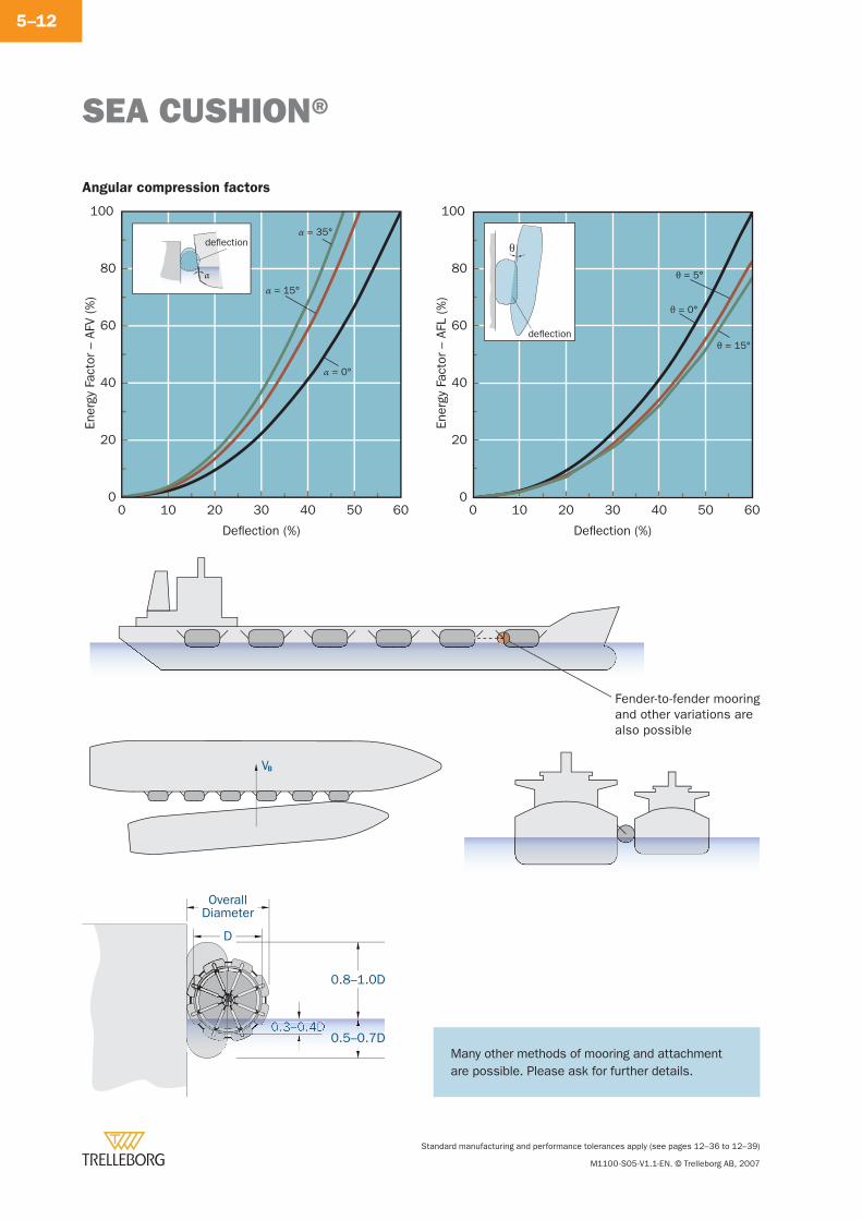
SEA CUSHION®
Standard manufacturing and performance tolerances apply (see pages 12–36 to 12–39)
M1100-S05-V1.1-EN. © Trelleborg AB, 2007
5–12
Angular compression factors
100
0 10 20 30 40 50 60
Ener
gy F
acto
r –
AFL
(%)
Deflection (%)
0
20
40
60
80
θ = 0°
θ = 15°
θ = 5°
θ
deflection
100
0 10 20 30 40 50 60
Ener
gy F
acto
r –
AFV
(%)
Deflection (%)
0
20
40
60
80
α = 0°
α = 15°
α = 35°deflection
α
VB
Fender-to-fender mooringand other variations arealso possible
0.3–0.4D
OverallDiameter
D
0.5–0.7D
0.8–1.0D
Many other methods of mooring and attachment are possible. Please ask for further details.
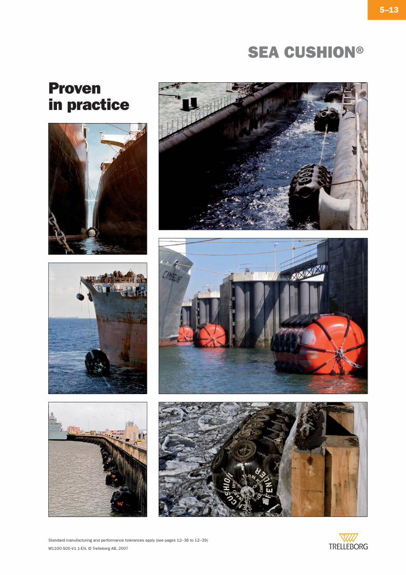
SEA CUSHION®
Standard manufacturing and performance tolerances apply (see pages 12–36 to 12–39)
M1100-S05-V1.1-EN. © Trelleborg AB, 2007
5–13
Provenin practice
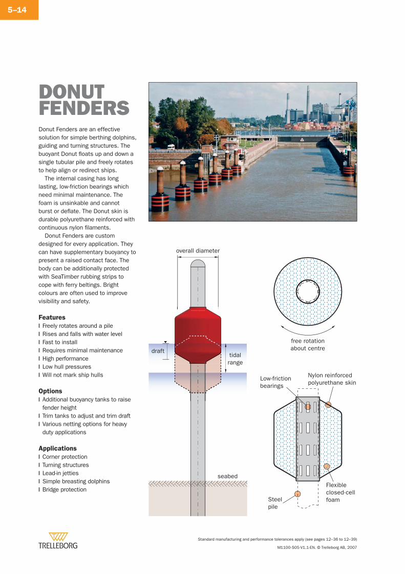
Standard manufacturing and performance tolerances apply (see pages 12–36 to 12–39)
M1100-S05-V1.1-EN. © Trelleborg AB, 2007
5–14
DONUTFENDERS
seabed
overall diameter
drafttidalrange
Steelpile
Flexibleclosed-cellfoam
Low-frictionbearings
Nylon reinforcedpolyurethane skin
free rotationabout centre
Donut Fenders are an effective solution for simple berthing dolphins, guiding and turning structures. The buoyant Donut fl oats up and down a single tubular pile and freely rotates to help align or redirect ships.
The internal casing has long lasting, low-friction bearings which need minimal maintenance. The foam is unsinkable and cannot burst or defl ate. The Donut skin is durable polyurethane reinforced with continuous nylon fi laments.
Donut Fenders are custom designed for every application. They can have supplementary buoyancy to present a raised contact face. The body can be additionally protected with SeaTimber rubbing strips to cope with ferry beltings. Bright colours are often used to improve visibility and safety.
Features
Freely rotates around a pileRises and falls with water levelFast to installRequires minimal maintenanceHigh performanceLow hull pressuresWill not mark ship hulls
Options
Additional buoyancy tanks to raise fender heightTrim tanks to adjust and trim draftVarious netting options for heavy duty applications
Applications
Corner protectionTurning structuresLead-in jettiesSimple breasting dolphinsBridge protection
�
�
�
�
�
�
�
�
�
�
�
�
�
�
�
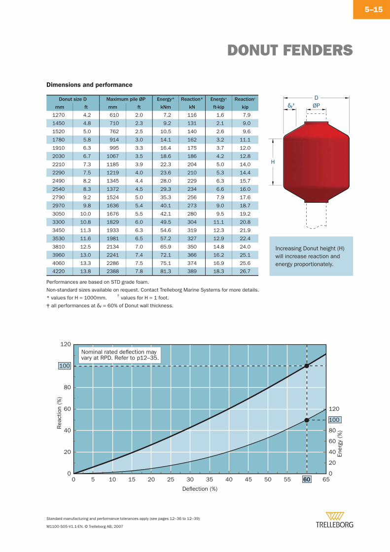
DONUT FENDERS
Standard manufacturing and performance tolerances apply (see pages 12–36 to 12–39)
M1100-S05-V1.1-EN. © Trelleborg AB, 2007
5–15
Dimensions and performance
Donut size D Maximum pile ØP Energy* Reaction* Energy† Reaction†
mm ft mm ft kNm kN ft-kip kip
1270 4.2 610 2.0 7.2 116 1.6 7.9
1450 4.8 710 2.3 9.2 131 2.1 9.0
1520 5.0 762 2.5 10.5 140 2.6 9.6
1780 5.8 914 3.0 14.1 162 3.2 11.1
1910 6.3 995 3.3 16.4 175 3.7 12.0
2030 6.7 1067 3.5 18.6 186 4.2 12.8
2210 7.3 1185 3.9 22.3 204 5.0 14.0
2290 7.5 1219 4.0 23.6 210 5.3 14.4
2490 8.2 1345 4.4 28.0 229 6.3 15.7
2540 8.3 1372 4.5 29.3 234 6.6 16.0
2790 9.2 1524 5.0 35.3 256 7.9 17.6
2970 9.8 1636 5.4 40.1 273 9.0 18.7
3050 10.0 1676 5.5 42.1 280 9.5 19.2
3300 10.8 1829 6.0 49.5 304 11.1 20.8
3450 11.3 1933 6.3 54.6 319 12.3 21.9
3530 11.6 1981 6.5 57.2 327 12.9 22.4
3810 12.5 2134 7.0 65.9 350 14.8 24.0
3960 13.0 2241 7.4 72.1 366 16.2 25.1
4060 13.3 2286 7.5 75.1 374 16.9 25.6
4220 13.8 2388 7.8 81.3 389 18.3 26.7
Performances are based on STD grade foam.
Non-standard sizes available on request. Contact Trelleborg Marine Systems for more details.
ØPδF‡
H
D
* values for H = 1000mm. † values for H = 1 foot.
‡ all performances at δF = 60% of Donut wall thickness.
60
100
100
0 5 10 15 20 25 30 35 40 45 50 55 60 65
Rea
ctio
n (%
)
Ener
gy (%
)
Deflection (%)
0
20
40
60
80
120
0
20
40
60
80
120
Nominal rated deflection mayvary at RPD. Refer to p12–35.
Increasing Donut height (H) will increase reaction and energy proportionately.
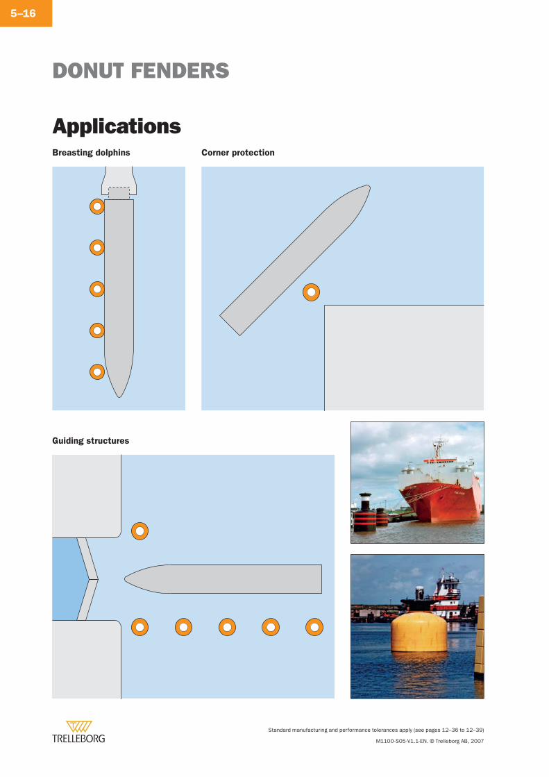
DONUT FENDERS
Standard manufacturing and performance tolerances apply (see pages 12–36 to 12–39)
M1100-S05-V1.1-EN. © Trelleborg AB, 2007
5–16
ApplicationsBreasting dolphins Corner protection
Guiding structures
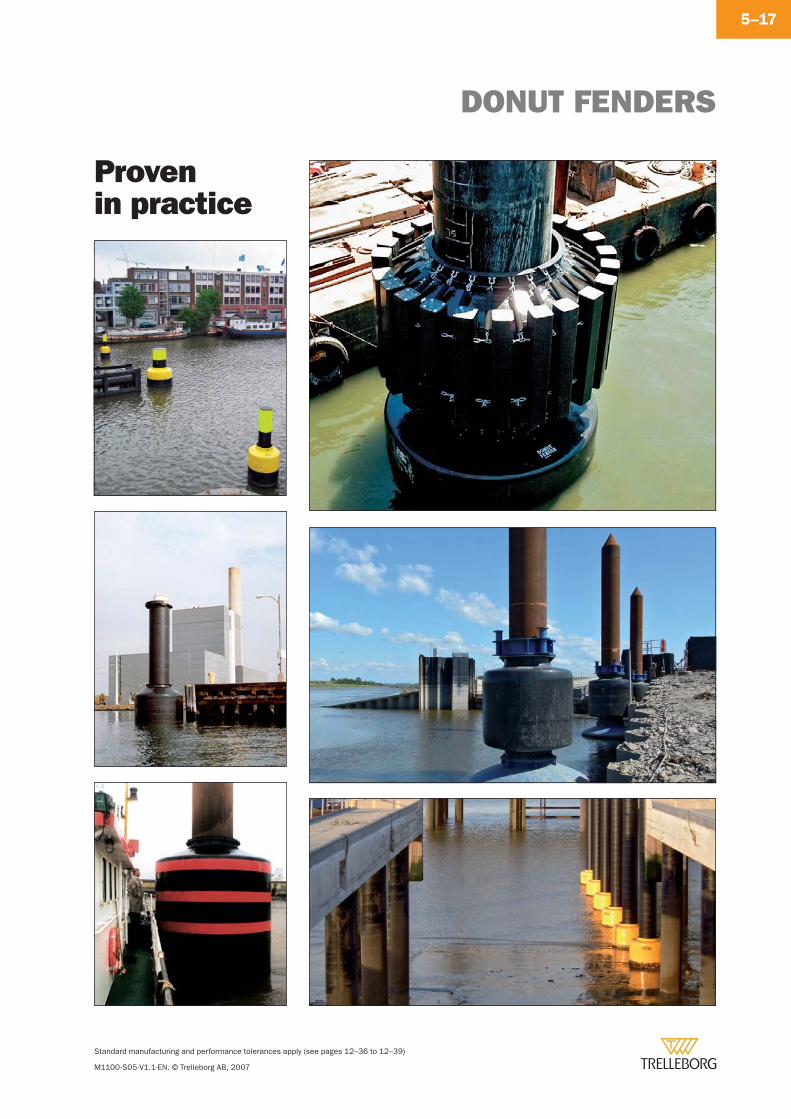
DONUT FENDERS
Standard manufacturing and performance tolerances apply (see pages 12–36 to 12–39)
M1100-S05-V1.1-EN. © Trelleborg AB, 2007
5–17
Provenin practice
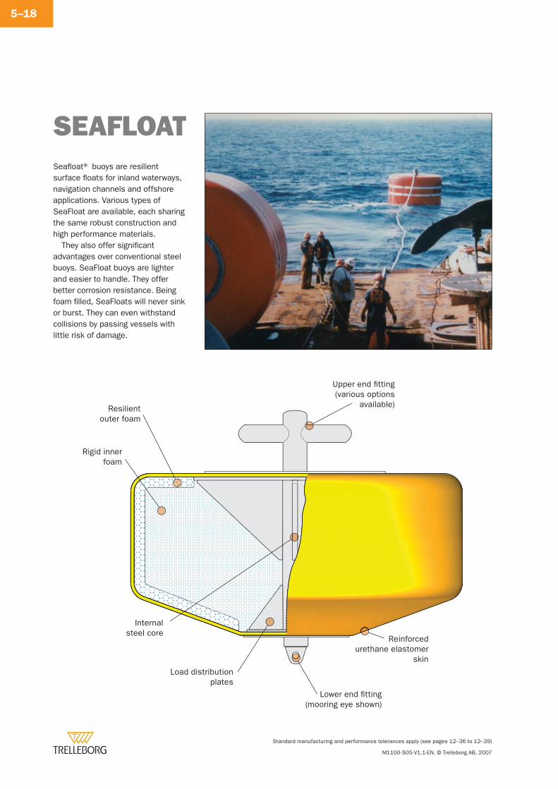
Standard manufacturing and performance tolerances apply (see pages 12–36 to 12–39)
M1100-S05-V1.1-EN. © Trelleborg AB, 2007
5–18
Seafl oat® buoys are resilient surface fl oats for inland waterways, navigation channels and offshore applications. Various types of SeaFloat are available, each sharing the same robust construction and high performance materials.
They also offer signifi cant advantages over conventional steel buoys. SeaFloat buoys are lighter and easier to handle. They offer better corrosion resistance. Being foam fi lled, SeaFloats will never sink or burst. They can even withstand collisions by passing vessels with little risk of damage.
SEAFLOAT
Reinforcedurethane elastomer
skin
Resilientouter foam
Rigid innerfoam
Upper end fitting(various options
available)
Lower end fitting(mooring eye shown)
Internalsteel core
Load distributionplates
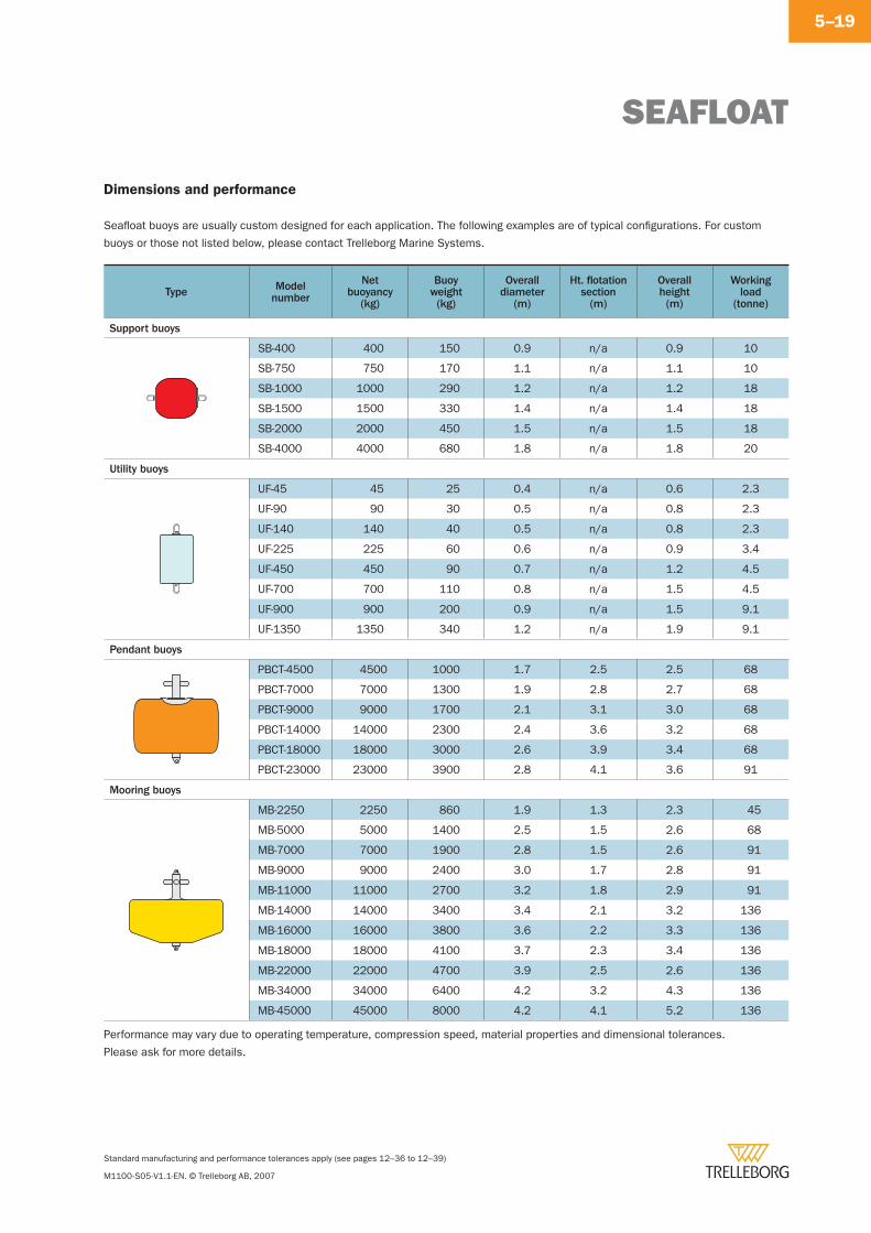
SEAFLOAT
Standard manufacturing and performance tolerances apply (see pages 12–36 to 12–39)
M1100-S05-V1.1-EN. © Trelleborg AB, 2007
5–19
Dimensions and performance
Seafl oat buoys are usually custom designed for each application. The following examples are of typical confi gurations. For custom
buoys or those not listed below, please contact Trelleborg Marine Systems.
Type Modelnumber
Netbuoyancy
(kg)
Buoyweight(kg)
Overalldiameter
(m)
Ht. fl otationsection
(m)
Overallheight
(m)
Workingload
(tonne)
Support buoys
SB-400 400 150 0.9 n/a 0.9 10
SB-750 750 170 1.1 n/a 1.1 10
SB-1000 1000 290 1.2 n/a 1.2 18
SB-1500 1500 330 1.4 n/a 1.4 18
SB-2000 2000 450 1.5 n/a 1.5 18
SB-4000 4000 680 1.8 n/a 1.8 20
Utility buoys
UF-45 45 25 0.4 n/a 0.6 2.3
UF-90 90 30 0.5 n/a 0.8 2.3
UF-140 140 40 0.5 n/a 0.8 2.3
UF-225 225 60 0.6 n/a 0.9 3.4
UF-450 450 90 0.7 n/a 1.2 4.5
UF-700 700 110 0.8 n/a 1.5 4.5
UF-900 900 200 0.9 n/a 1.5 9.1
UF-1350 1350 340 1.2 n/a 1.9 9.1
Pendant buoys
PBCT-4500 4500 1000 1.7 2.5 2.5 68
PBCT-7000 7000 1300 1.9 2.8 2.7 68
PBCT-9000 9000 1700 2.1 3.1 3.0 68
PBCT-14000 14000 2300 2.4 3.6 3.2 68
PBCT-18000 18000 3000 2.6 3.9 3.4 68
PBCT-23000 23000 3900 2.8 4.1 3.6 91
Mooring buoys
MB-2250 2250 860 1.9 1.3 2.3 45
MB-5000 5000 1400 2.5 1.5 2.6 68
MB-7000 7000 1900 2.8 1.5 2.6 91
MB-9000 9000 2400 3.0 1.7 2.8 91
MB-11000 11000 2700 3.2 1.8 2.9 91
MB-14000 14000 3400 3.4 2.1 3.2 136
MB-16000 16000 3800 3.6 2.2 3.3 136
MB-18000 18000 4100 3.7 2.3 3.4 136
MB-22000 22000 4700 3.9 2.5 2.6 136
MB-34000 34000 6400 4.2 3.2 4.3 136
MB-45000 45000 8000 4.2 4.1 5.2 136
Performance may vary due to operating temperature, compression speed, material properties and dimensional tolerances.
Please ask for more details.
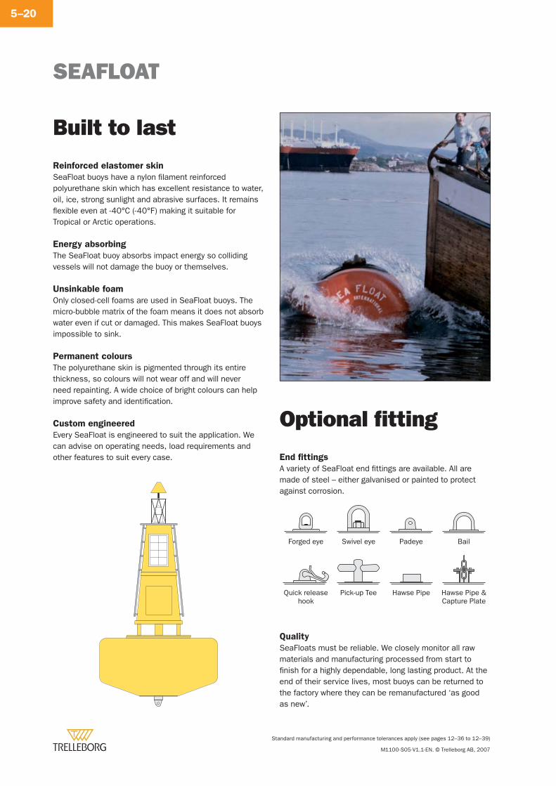
SEAFLOAT
Standard manufacturing and performance tolerances apply (see pages 12–36 to 12–39)
M1100-S05-V1.1-EN. © Trelleborg AB, 2007
5–20
End fi ttings
A variety of SeaFloat end fi ttings are available. All are made of steel – either galvanised or painted to protect against corrosion.
Forged eye Swivel eye Padeye Bail
Quick release hook
Pick-up Tee Hawse Pipe Hawse Pipe & Capture Plate
Quality
SeaFloats must be reliable. We closely monitor all raw materials and manufacturing processed from start to fi nish for a highly dependable, long lasting product. At the end of their service lives, most buoys can be returned to the factory where they can be remanufactured ‘as good as new’.
Reinforced elastomer skin
SeaFloat buoys have a nylon fi lament reinforced polyurethane skin which has excellent resistance to water, oil, ice, strong sunlight and abrasive surfaces. It remains fl exible even at -40°C (-40°F) making it suitable for Tropical or Arctic operations.
Energy absorbing
The SeaFloat buoy absorbs impact energy so colliding vessels will not damage the buoy or themselves.
Unsinkable foam
Only closed-cell foams are used in SeaFloat buoys. The micro-bubble matrix of the foam means it does not absorb water even if cut or damaged. This makes SeaFloat buoys impossible to sink.
Permanent colours
The polyurethane skin is pigmented through its entire thickness, so colours will not wear off and will never need repainting. A wide choice of bright colours can help improve safety and identifi cation.
Custom engineered
Every SeaFloat is engineered to suit the application. We can advise on operating needs, load requirements and other features to suit every case.
Built to last
Optional fi tting
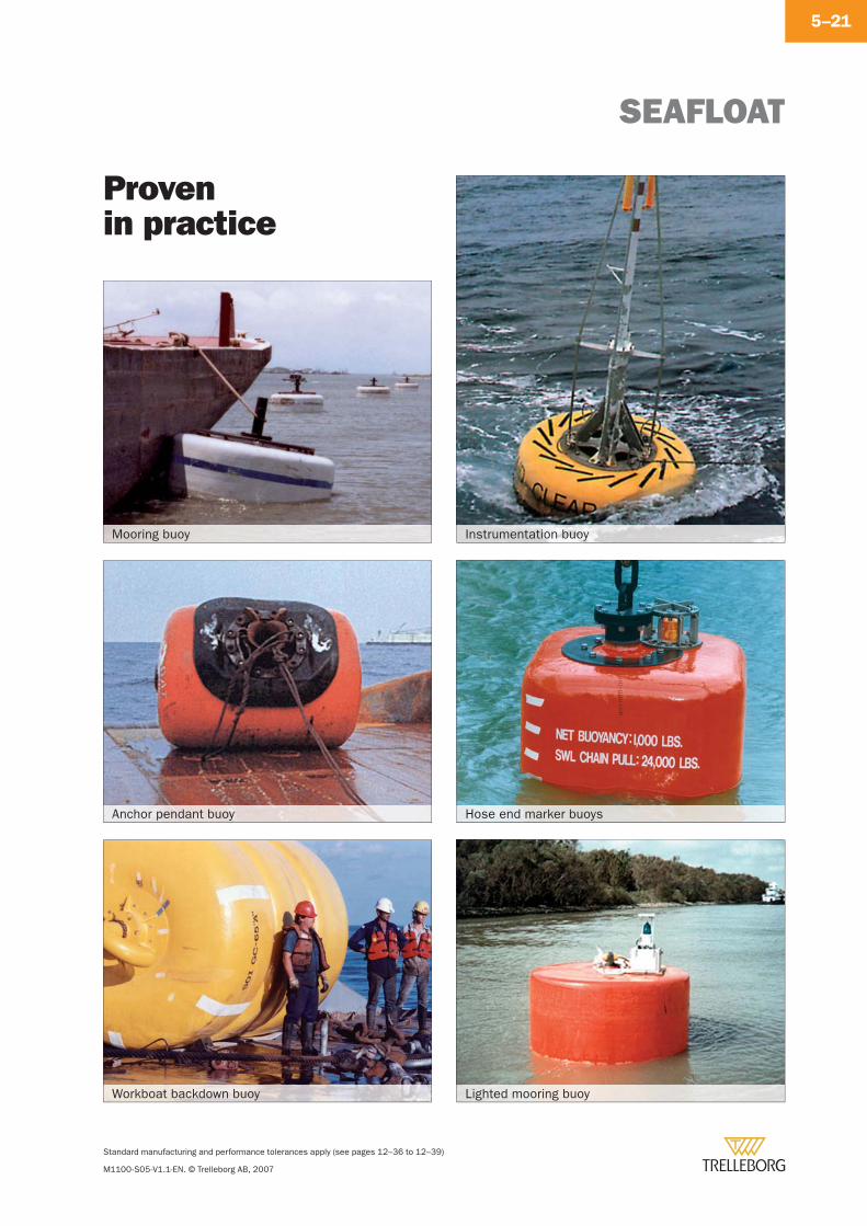
SEAFLOAT
Standard manufacturing and performance tolerances apply (see pages 12–36 to 12–39)
M1100-S05-V1.1-EN. © Trelleborg AB, 2007
5–21
Provenin practice
Mooring buoy
Anchor pendant buoy
Instrumentation buoy
Workboat backdown buoy Lighted mooring buoy
Hose end marker buoys

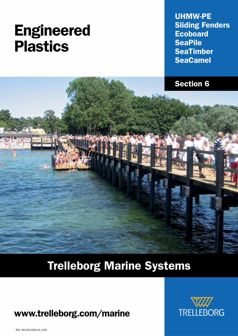
UHMW-PESliding FendersEcoboardSeaPileSeaTimberSeaCamel
EngineeredPlastics
Ref. M1100-S06-V1.1-EN
Section 6
www.trelleborg.com/marine
Trelleborg Marine Systems
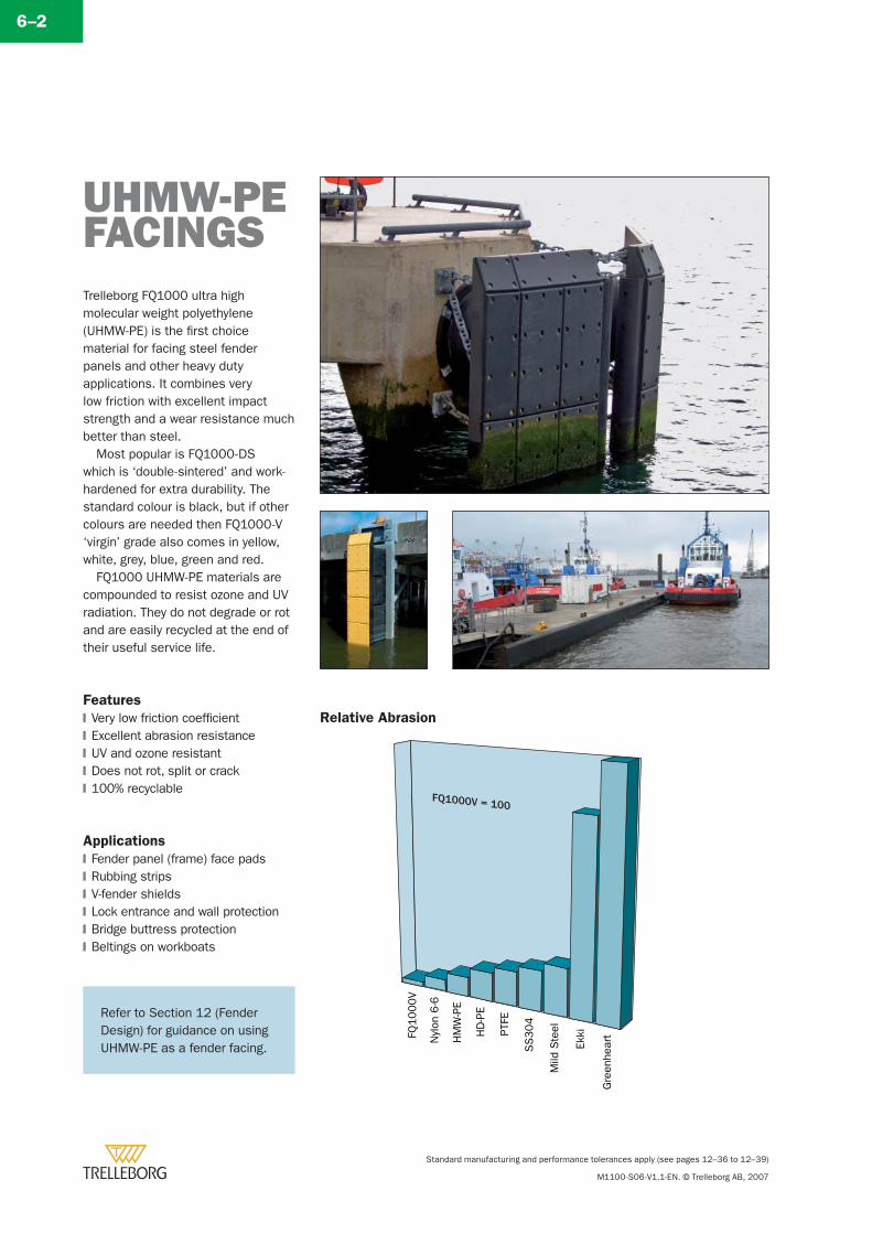
Standard manufacturing and performance tolerances apply (see pages 12–36 to 12–39)
M1100-S06-V1.1-EN. © Trelleborg AB, 2007
6–2
Trelleborg FQ1000 ultra high molecular weight polyethylene (UHMW-PE) is the fi rst choice material for facing steel fender panels and other heavy duty applications. It combines very low friction with excellent impact strength and a wear resistance much better than steel.
Most popular is FQ1000-DS which is ‘double-sintered’ and work-hardened for extra durability. The standard colour is black, but if other colours are needed then FQ1000-V ‘virgin’ grade also comes in yellow, white, grey, blue, green and red.
FQ1000 UHMW-PE materials are compounded to resist ozone and UV radiation. They do not degrade or rot and are easily recycled at the end of their useful service life.
Features
Very low friction coeffi cientExcellent abrasion resistanceUV and ozone resistantDoes not rot, split or crack100% recyclable
Applications
Fender panel (frame) face padsRubbing stripsV-fender shieldsLock entrance and wall protectionBridge buttress protectionBeltings on workboats
�
�
�
�
�
�
�
�
�
�
�
UHMW-PEFACINGS
Relative Abrasion
Refer to Section 12 (Fender Design) for guidance on using UHMW-PE as a fender facing.
FQ1000V = 100
FQ1
00
0V
Nyl
on6-6
HM
W-P
E
HD
-PE
PTFE
SS
304
Mild
Ste
el
Ekki
Gre
enhe
art
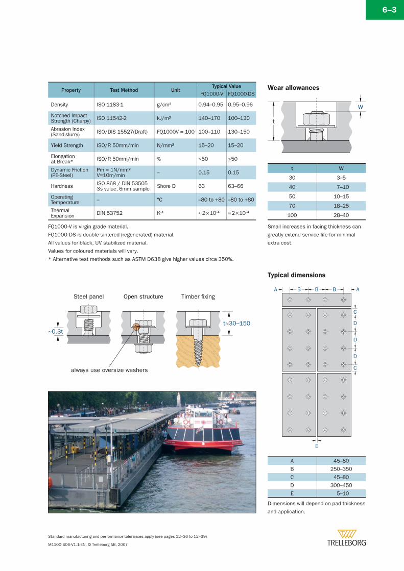
Standard manufacturing and performance tolerances apply (see pages 12–36 to 12–39)
M1100-S06-V1.1-EN. © Trelleborg AB, 2007
6–3
Steel panel Open structure Timber fixing
t≈30–150
always use oversize washers
~0.3t
Dimensions will depend on pad thickness
and application.
t
W
Wear allowances
t W
30 3–5
40 7–10
50 10–15
70 18–25
100 28–40
Small increases in facing thickness can
greatly extend service life for minimal
extra cost.
A
C
D
BB B
E
A
C
D
D
A 45–80
B 250–350
C 45–80
D 300–450
E 5–10
Typical dimensions
FQ1000-V is virgin grade material.
FQ1000-DS is double sintered (regenerated) material.
All values for black, UV stabilized material.
Values for coloured materials will vary.
* Alternative test methods such as ASTM D638 give higher values circa 350%.
Property Test Method UnitTypical Value
FQ1000-V FQ1000-DS
Density ISO 1183-1 g/cm3 0.94–0.95 0.95–0.96
Notched ImpactStrength (Charpy) ISO 11542-2 kJ/m2 140–170 100–130
Abrasion Index(Sand-slurry) ISO/DIS 15527(Draft) FQ1000V = 100 100–110 130–150
Yield Strength ISO/R 50mm/min N/mm2 15–20 15–20
Elongationat Break* ISO/R 50mm/min % >50 >50
Dynamic Friction(PE-Steel)
Pm = 1N/mm2V=10m/min – 0.15 0.15
Hardness ISO 868 / DIN 535053s value, 6mm sample Shore D 63 63–66
OperatingTemperature – °C –80 to +80 –80 to +80
ThermalExpansion DIN 53752 K–1 ≈ 2 × 10⁻⁴ ≈ 2 × 10⁻⁴
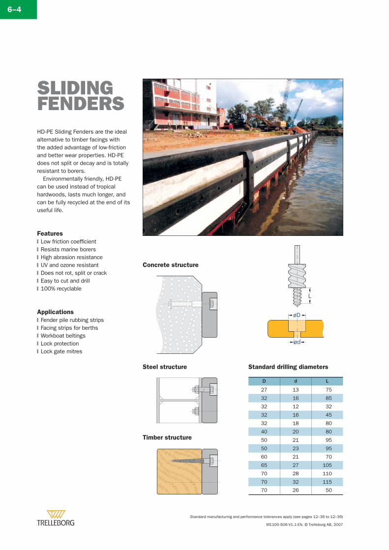
Standard manufacturing and performance tolerances apply (see pages 12–36 to 12–39)
M1100-S06-V1.1-EN. © Trelleborg AB, 2007
6–4
HD-PE Sliding Fenders are the ideal alternative to timber facings with the added advantage of low-friction and better wear properties. HD-PE does not split or decay and is totally resistant to borers.
Environmentally friendly, HD-PE can be used instead of tropical hardwoods, lasts much longer, and can be fully recycled at the end of its useful life.
Features
Low friction coeffi cientResists marine borersHigh abrasion resistanceUV and ozone resistantDoes not rot, split or crackEasy to cut and drill100% recyclable
Applications
Fender pile rubbing stripsFacing strips for berthsWorkboat beltingsLock protectionLock gate mitres
�
�
�
�
�
�
�
�
�
�
�
�
Standard drilling diameters
D d L
27 13 75
32 16 85
32 12 32
32 16 45
32 18 80
40 20 80
50 21 95
50 23 95
60 21 70
65 27 105
70 28 110
70 32 115
70 26 50
SLIDING FENDERS
L
øD
ød
Concrete structure
Steel structure
Timber structure
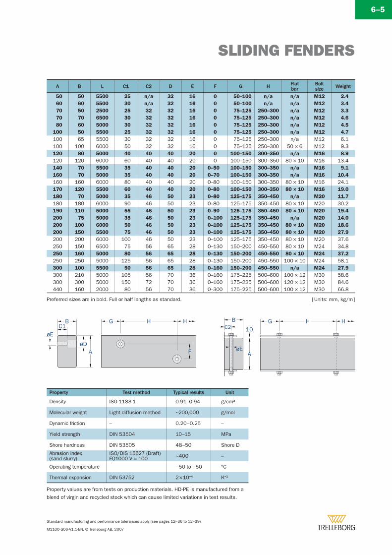
SLIDING FENDERS
Standard manufacturing and performance tolerances apply (see pages 12–36 to 12–39)
M1100-S06-V1.1-EN. © Trelleborg AB, 2007
6–5
A B L C1 C2 D E F G H Flatbar
Boltsize Weight
50 50 5500 25 n/a 32 16 0 50–100 n/a n/a M12 2.4
60 60 5500 30 n/a 32 16 0 50–100 n/a n/a M12 3.4
70 50 2500 25 32 32 16 0 75–125 250–300 n/a M12 3.3
70 70 6500 30 32 32 16 0 75–125 250–300 n/a M12 4.6
80 60 5000 30 32 32 16 0 75–125 250–300 n/a M12 4.5
100 50 5500 25 32 32 16 0 75–125 250–300 n/a M12 4.7
100 65 5500 30 32 32 16 0 75–125 250–300 n/a M12 6.1100 100 6000 50 32 32 16 0 75–125 250–300 50 × 6 M12 9.3120 80 5000 40 40 40 20 0 100–150 300–350 n/a M16 8.9
120 120 6000 60 40 40 20 0 100–150 300–350 80 × 10 M16 13.4140 70 5500 35 40 40 20 0–50 100–150 300–350 n/a M16 9.1
160 70 5000 35 40 40 20 0–70 100–150 300–350 n/a M16 10.4
160 160 6000 80 40 40 20 0–80 100–150 300–350 80 × 10 M16 24.1170 120 5500 60 40 40 20 0–80 100–150 300–350 80 × 10 M16 19.0
180 70 5000 35 46 50 23 0–80 125–175 350–450 n/a M20 11.7
180 180 6000 90 46 50 23 0–80 125–175 350–450 80 × 10 M20 30.2190 110 5000 55 46 50 23 0–90 125–175 350–450 80 × 10 M20 19.4
200 75 5000 35 46 50 23 0–100 125–175 350–450 n/a M20 14.0
200 100 6000 50 46 50 23 0–100 125–175 350–450 80 × 10 M20 18.6
200 150 5500 75 46 50 23 0–100 125–175 350–450 80 × 10 M20 27.9
200 200 6000 100 46 50 23 0–100 125–175 350–450 80 × 10 M20 37.6250 150 6500 75 56 65 28 0–130 150–200 450–550 80 × 10 M24 34.8250 160 5000 80 56 65 28 0–130 150–200 450–550 80 × 10 M24 37.2
250 250 5000 125 56 65 28 0–130 150–200 450–550 100 × 10 M24 58.1300 100 5500 50 56 65 28 0–160 150–200 450–550 n/a M24 27.9
300 210 5000 105 56 70 36 0–160 175–225 500–600 100 × 12 M30 58.6300 300 5000 150 72 70 36 0–160 175–225 500–600 120 × 12 M30 84.6440 160 2000 80 56 70 36 0–300 175–225 500–600 100 × 12 M30 66.8
Property Test method Typical results Unit
Density ISO 1183-1 0.91–0.94 g/cm3
Molecular weight Light diffusion method ~200,000 g/mol
Dynamic friction – 0.20–0.25 –
Yield strength DIN 53504 10–15 MPa
Shore hardness DIN 53505 48–50 Shore D
Abrasion index(sand slurry)
ISO/DIS 15527 (Draft)FQ1000-V = 100 ~400 –
Operating temperature −50 to +50 °C
Thermal expansion DIN 53752 2 × 10⁻⁴ K−1
[ Units: mm, kg/m ]
AøD
øEC1
B G H H
F
C2
øE
10
A
B G H H
Preferred sizes are in bold. Full or half lengths as standard.
Property values are from tests on production materials. HD-PE is manufactured from a
blend of virgin and recycled stock which can cause limited variations in test results.
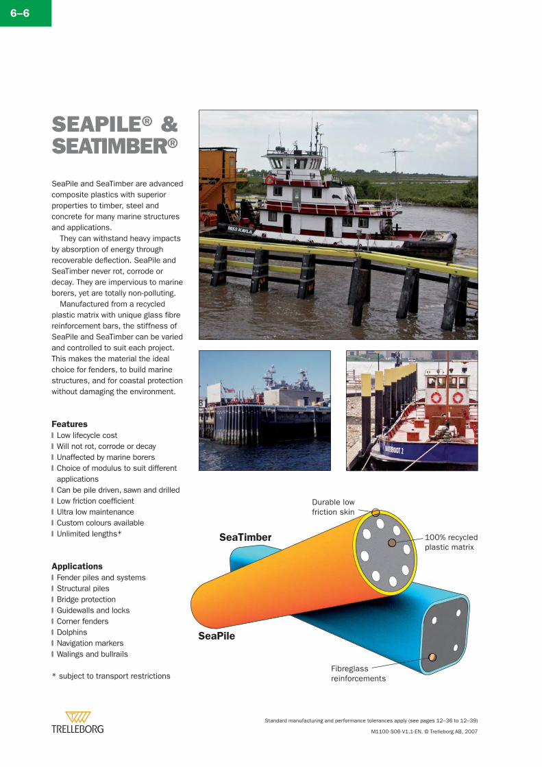
Standard manufacturing and performance tolerances apply (see pages 12–36 to 12–39)
M1100-S06-V1.1-EN. © Trelleborg AB, 2007
SEAPILE® &SEATIMBER®SeaPile and SeaTimber are advanced composite plastics with superior properties to timber, steel and concrete for many marine structures and applications.
They can withstand heavy impacts by absorption of energy through recoverable defl ection. SeaPile and SeaTimber never rot, corrode or decay. They are impervious to marine borers, yet are totally non-polluting.
Manufactured from a recycled plastic matrix with unique glass fi bre reinforcement bars, the stiffness of SeaPile and SeaTimber can be varied and controlled to suit each project. This makes the material the ideal choice for fenders, to build marine structures, and for coastal protection without damaging the environment.
Features
Low lifecycle costWill not rot, corrode or decayUnaffected by marine borersChoice of modulus to suit different applicationsCan be pile driven, sawn and drilledLow friction coeffi cientUltra low maintenanceCustom colours availableUnlimited lengths*
Applications
Fender piles and systemsStructural pilesBridge protectionGuidewalls and locksCorner fendersDolphinsNavigation markersWalings and bullrails
* subject to transport restrictions
�
�
�
�
�
�
�
�
�
�
�
�
�
�
�
�
�
100% recycledplastic matrix
Durable lowfriction skin
Fibreglassreinforcements
SeaPile
SeaTimber
6–6
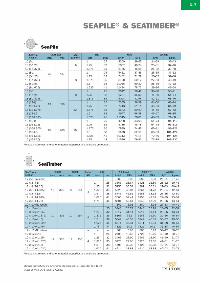
SEAPILE® & SEATIMBER®
Standard manufacturing and performance tolerances apply (see pages 12–36 to 12–39)
M1100-S06-V1.1-EN. © Trelleborg AB, 2007
SeaTimber
SeaPile
Modulus, stiffness and other material properties are available on request.
SeaPilesection
Diameter Rebarquantity
Size Yield Weightinch mm inch mm lb/in2 MPa lb/ft kg/m
10 (6-1)
10 254
61 25 4300 29.65 24–29 36–43
10 (6-1.25) 1.25 32 5837 40.24 25–31 37–4610 (6-1.375) 1.375 35 6766 46.65 26–32 39–4810 (8-1)
8
1 25 5431 37.45 25–35 37–5210 (8-1.25) 1.25 32 7482 51.59 26–32 39–4810 (8-1.375) 1.375 35 8720 60.12 27–33 40–4910 (8-1.5) 1.5 38 10036 69.20 28–35 42–5210 (8-1.625) 1.625 41 11424 78.77 29–36 43–5413 (8-1)
13 330
81 25 3842 26.49 39–48 58–71
13 (8-1.25) 1.25 32 5207 35.90 41–50 61–7413 (8-1.375) 1.375 35 6028 41.56 42–51 63–7613 (12-1)
12
1 25 5365 36.99 41–50 61–7413 (12-1.25) 1.25 32 7413 51.11 43–53 64–7913 (12-1.375) 1.375 35 8643 59.59 45–55 67–8213 (12-1.5) 1.5 38 9947 68.58 46–57 68–8513 (12-1.625) 1.625 41 11315 78.01 48–59 71–8816 (16-1)
16 406 16
1 25 4928 33.98 61–74 91–11016 (16-1.25) 1.25 32 6785 46.78 64–78 95–11616 (16-1.375) 1.375 35 7899 54.46 66–81 98–12116 (16-1.5) 1.5 38 9078 62.59 68–83 101–12416 (16-1.625) 1.625 41 10313 71.11 70–86 104–12816 (16-1.75) 1.75 44 11599 79.97 73–89 109–132
SeaTimbersection
Height Width Rebar qty
Size Yield X-X Yield Y-Y Weightinch mm inch mm inch mm lb/in2 MPa lb/in2 MPa lb/ft kg/m
12 × 8 (No rebar)
12 305 8 254
– – – 860 5.93 860 5.93 25–31 37–4612 × 8 (4-1)
4
1 25 3868 26.67 3421 23.59 26–32 39–4812 × 8 (4-1.25) 1.25 32 5155 35.54 4381 30.21 27–33 40–4912 × 8 (4-1.375) 1.375 35 5928 40.87 4964 34.23 28–34 42–5112 × 8 (4-1.5) 1.5 38 6746 46.51 5588 38.53 28–35 42–5212 × 8 (4-1.625) 1.625 41 7606 52.44 6250 43.09 29–35 43–5212 × 8 (4-1.75) 1.75 44 8501 58.61 6948 47.90 29–36 43–5410 × 10 (No rebar)
10 305 10 254
– – – 860 5.93 860 5.93 27–33 40–4910 × 10 (4-1)
4
1 25 3443 23.74 3443 23.74 28–35 42–5210 × 10 (4-1.25) 1.25 32 4517 31.14 4517 31.14 29–36 43–5410 × 10 (4-1.375) 1.375 35 5163 35.6 5163 35.60 30–36 45–5410 × 10 (4-1.5) 1.5 38 5849 40.33 5849 40.33 30–37 45–5510 × 10 (4-1.625) 1.625 41 6571 45.31 6571 45.31 31–38 46–5710 × 10 (4-1.75) 1.75 44 7325 50.5 7325 50.5 31–38 46–5712 × 12 (No rebar)
12 305 12 305
– – – 860 5.93 860 5.93 39–47 58–7012 × 12 (4-1)
4
1 25 2706 18.66 2706 18.66 40–49 60–7312 × 12 (4-1.25) 1.25 32 3466 23.90 3466 23.90 41–50 61–7412 × 12 (4-1.375) 1.375 35 3923 27.05 3923 27.05 41–51 61–7612 × 12 (4-1.5) 1.5 38 4406 30.38 4406 30.38 42–51 63–7612 × 12 (4-1.625) 1.625 41 4914 33.88 4914 33.88 42–52 63–77
Modulus, stiffness and other material properties are available on request.
6–7
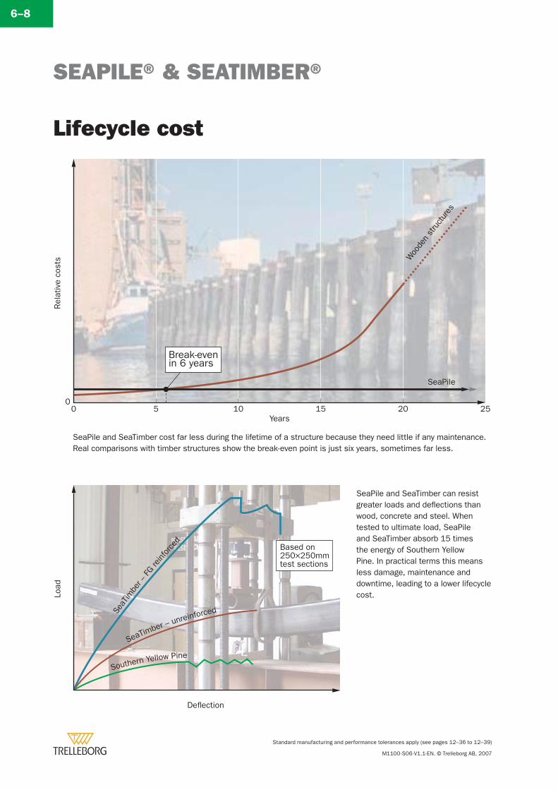
SEAPILE® & SEATIMBER®
Standard manufacturing and performance tolerances apply (see pages 12–36 to 12–39)
M1100-S06-V1.1-EN. © Trelleborg AB, 2007
SeaPile and SeaTimber cost far less during the lifetime of a structure because they need little if any maintenance. Real comparisons with timber structures show the break-even point is just six years, sometimes far less.
Lifecycle cost
Rel
ativ
e co
sts
Years
05 10 15 20 25
Break-evenin 6 years
SeaPile
0W
oode
nst
ruct
ures
SeaPile and SeaTimber can resist greater loads and defl ections than wood, concrete and steel. When tested to ultimate load, SeaPile and SeaTimber absorb 15 times the energy of Southern Yellow Pine. In practical terms this means less damage, maintenance and downtime, leading to a lower lifecycle cost.
SeaT
imbe
r –FG
reinf
orce
d
SeaTimber – unreinforced
Southern Yellow Pine
Load
Deflection
Based on250×250mmtest sections
6–8
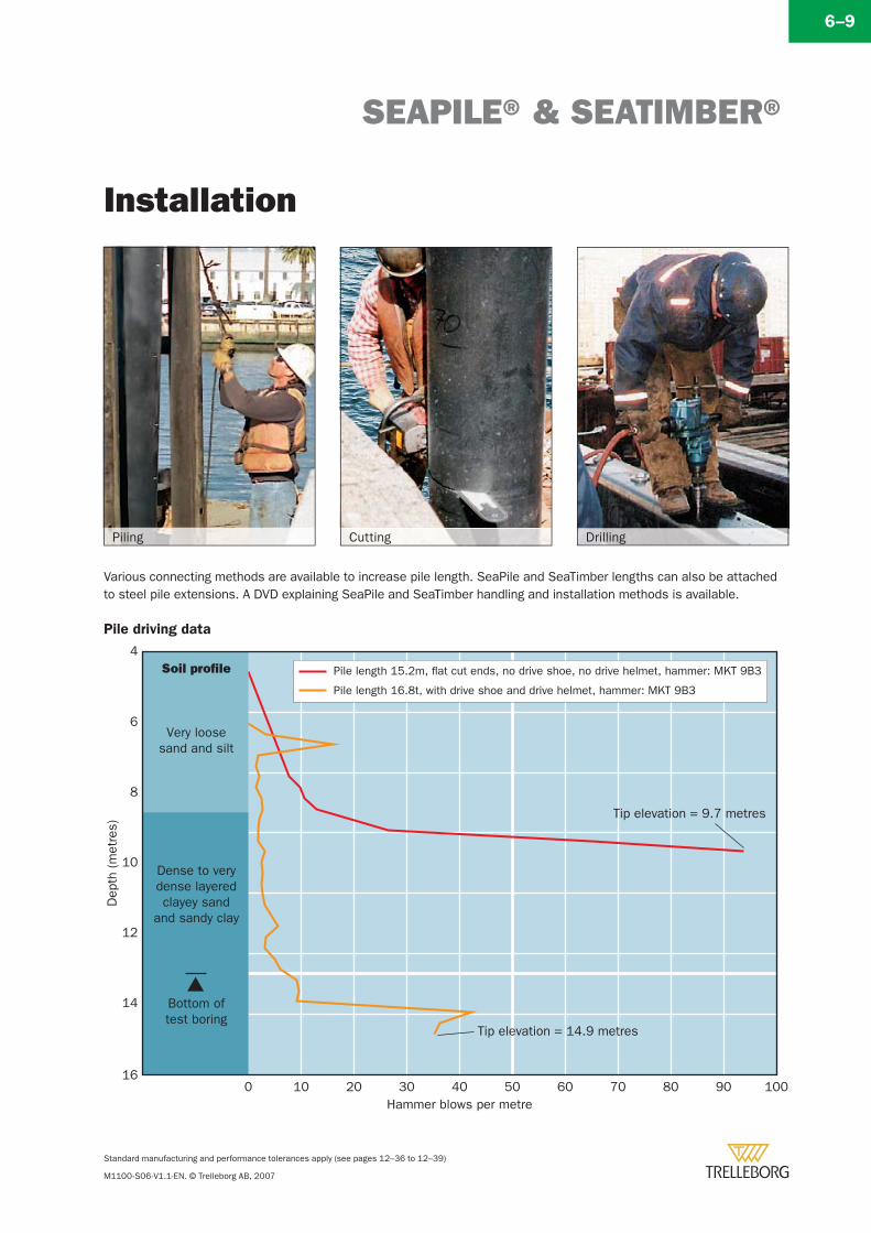
SEAPILE® & SEATIMBER®
Standard manufacturing and performance tolerances apply (see pages 12–36 to 12–39)
M1100-S06-V1.1-EN. © Trelleborg AB, 2007
Installation
1000 10 20 30 40 50 60 70 80 90
Tip elevation = 9.7 metres
Tip elevation = 14.9 metres
16
14
12
10
8
6
4
Dep
th (m
etre
s)
Hammer blows per metre
Soil profile
Very loosesand and silt
Dense to verydense layeredclayey sand
and sandy clay
Bottom oftest boring
Pile length 15.2m, flat cut ends, no drive shoe, no drive helmet, hammer: MKT 9B3
Pile length 16.8t, with drive shoe and drive helmet, hammer: MKT 9B3
Pile driving data
DrillingCuttingPiling
6–9
Various connecting methods are available to increase pile length. SeaPile and SeaTimber lengths can also be attached to steel pile extensions. A DVD explaining SeaPile and SeaTimber handling and installation methods is available.
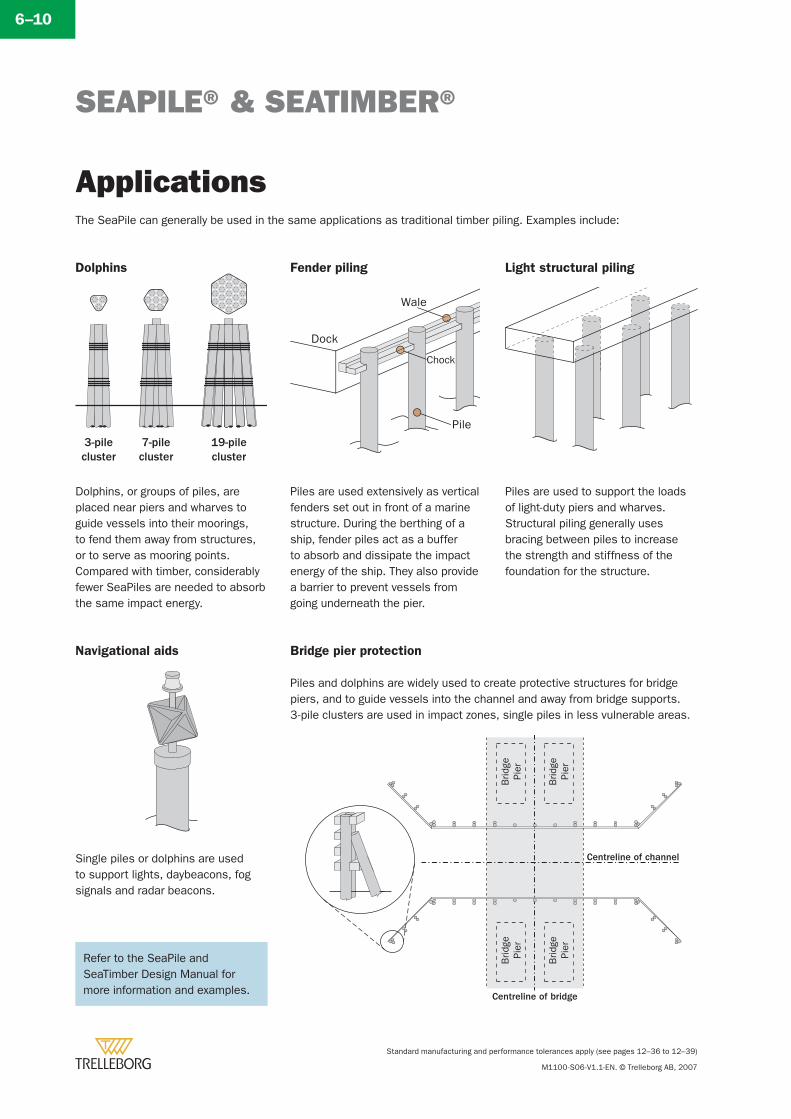
SEAPILE® & SEATIMBER®
Standard manufacturing and performance tolerances apply (see pages 12–36 to 12–39)
M1100-S06-V1.1-EN. © Trelleborg AB, 2007
ApplicationsThe SeaPile can generally be used in the same applications as traditional timber piling. Examples include:
Pile
Wale
Dock
Chock
Brid
gePi
er
Brid
gePi
er
Brid
gePi
er
Brid
gePi
er
Centreline of bridge
Centreline of channel
Fender piling
Piles are used extensively as vertical fenders set out in front of a marine structure. During the berthing of a ship, fender piles act as a buffer to absorb and dissipate the impact energy of the ship. They also provide a barrier to prevent vessels from going underneath the pier.
Navigational aids
Single piles or dolphins are used to support lights, daybeacons, fog signals and radar beacons.
Light structural piling
Piles are used to support the loads of light-duty piers and wharves. Structural piling generally uses bracing between piles to increase the strength and stiffness of the foundation for the structure.
Dolphins
Dolphins, or groups of piles, are placed near piers and wharves to guide vessels into their moorings, to fend them away from structures, or to serve as mooring points. Compared with timber, considerably fewer SeaPiles are needed to absorb the same impact energy.
Bridge pier protection
Piles and dolphins are widely used to create protective structures for bridge piers, and to guide vessels into the channel and away from bridge supports.3-pile clusters are used in impact zones, single piles in less vulnerable areas.
3-pilecluster
7-pilecluster
19-pilecluster
Refer to the SeaPile and SeaTimber Design Manual for more information and examples.
6–10
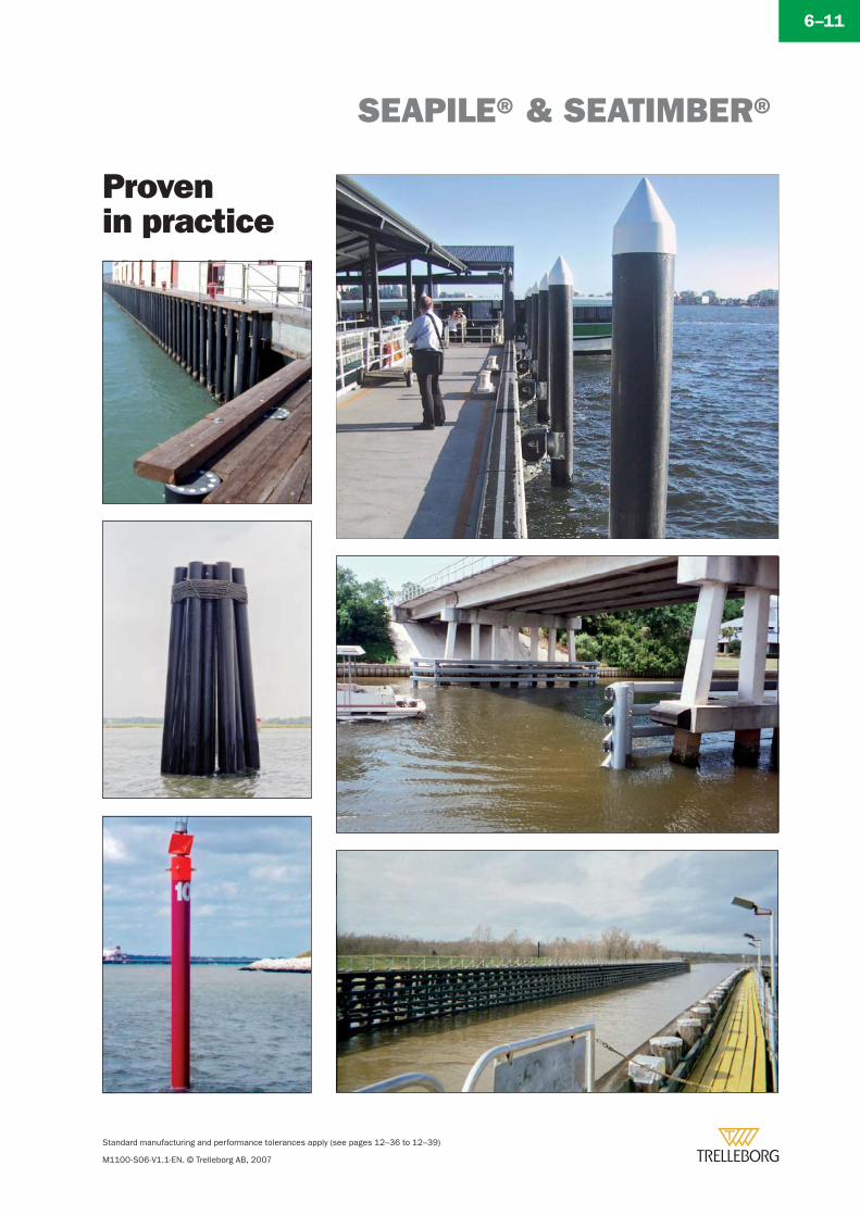
SEAPILE® & SEATIMBER®
Standard manufacturing and performance tolerances apply (see pages 12–36 to 12–39)
M1100-S06-V1.1-EN. © Trelleborg AB, 2007
Provenin practice
6–11
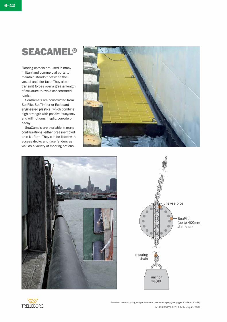
Standard manufacturing and performance tolerances apply (see pages 12–36 to 12–39)
M1100-S06-V1.1-EN. © Trelleborg AB, 2007
6–12
SEACAMEL®Floating camels are used in many military and commercial ports to maintain standoff between the vessel and pier face. They also transmit forces over a greater length of structure to avoid concentrated loads.
SeaCamels are constructed from SeaPile, SeaTimber or Ecoboard engineered plastics, which combine high strength with positive buoyancy and will not crush, split, corrode or decay.
SeaCamels are available in many confi gurations, either preassembled or in kit form. They can be fi tted with access decks and face fenders as well as a variety of mooring options.
hawse pipe
SeaPile(up to 400mmdiameter)
mooringchain
anchorweight
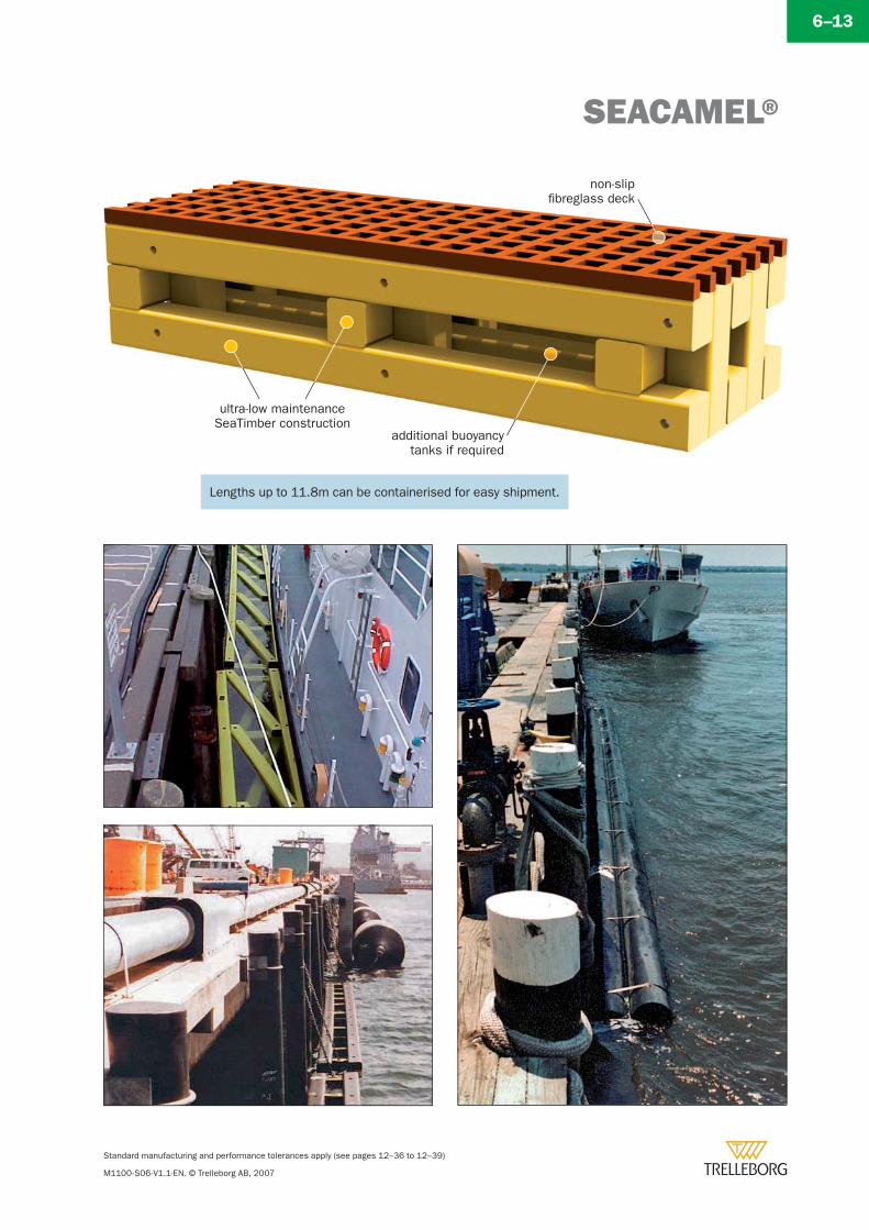
SEACAMEL®
Standard manufacturing and performance tolerances apply (see pages 12–36 to 12–39)
M1100-S06-V1.1-EN. © Trelleborg AB, 2007
6–13
ultra-low maintenanceSeaTimber construction
additional buoyancytanks if required
non-slipfibreglass deck
Lengths up to 11.8m can be containerised for easy shipment.
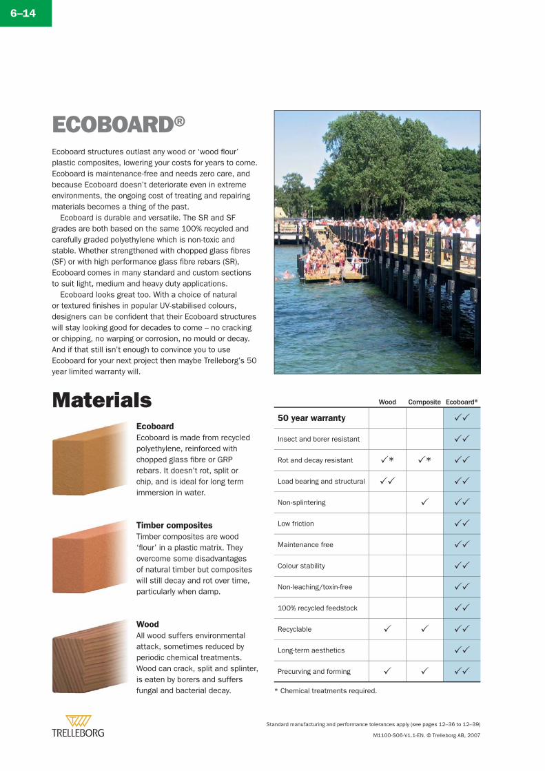
Standard manufacturing and performance tolerances apply (see pages 12–36 to 12–39)
M1100-S06-V1.1-EN. © Trelleborg AB, 2007
6–14
ECOBOARD®Ecoboard structures outlast any wood or ‘wood fl our’ plastic composites, lowering your costs for years to come. Ecoboard is maintenance-free and needs zero care, and because Ecoboard doesn’t deteriorate even in extreme environments, the ongoing cost of treating and repairing materials becomes a thing of the past.
Ecoboard is durable and versatile. The SR and SF grades are both based on the same 100% recycled and carefully graded polyethylene which is non-toxic and stable. Whether strengthened with chopped glass fi bres (SF) or with high performance glass fi bre rebars (SR), Ecoboard comes in many standard and custom sections to suit light, medium and heavy duty applications.
Ecoboard looks great too. With a choice of natural or textured fi nishes in popular UV-stabilised colours, designers can be confi dent that their Ecoboard structures will stay looking good for decades to come – no cracking or chipping, no warping or corrosion, no mould or decay. And if that still isn’t enough to convince you to use Ecoboard for your next project then maybe Trelleborg’s 50 year limited warranty will.
Ecoboard
Ecoboard is made from recycled polyethylene, reinforced with chopped glass fi bre or GRP rebars. It doesn’t rot, split or chip, and is ideal for long term immersion in water.
Timber composites
Timber composites are wood ‘fl our’ in a plastic matrix. They overcome some disadvantages of natural timber but composites will still decay and rot over time, particularly when damp.
Wood
All wood suffers environmental attack, sometimes reduced by periodic chemical treatments. Wood can crack, split and splinter, is eaten by borers and suffers fungal and bacterial decay.
Materials Wood Composite Ecoboard®
50 year warranty
Insect and borer resistant
Rot and decay resistant * *
Load bearing and structural
Non-splintering
Low friction
Maintenance free
Colour stability
Non-leaching/toxin-free
100% recycled feedstock
Recyclable
Long-term aesthetics
Precurving and forming
* Chemical treatments required.
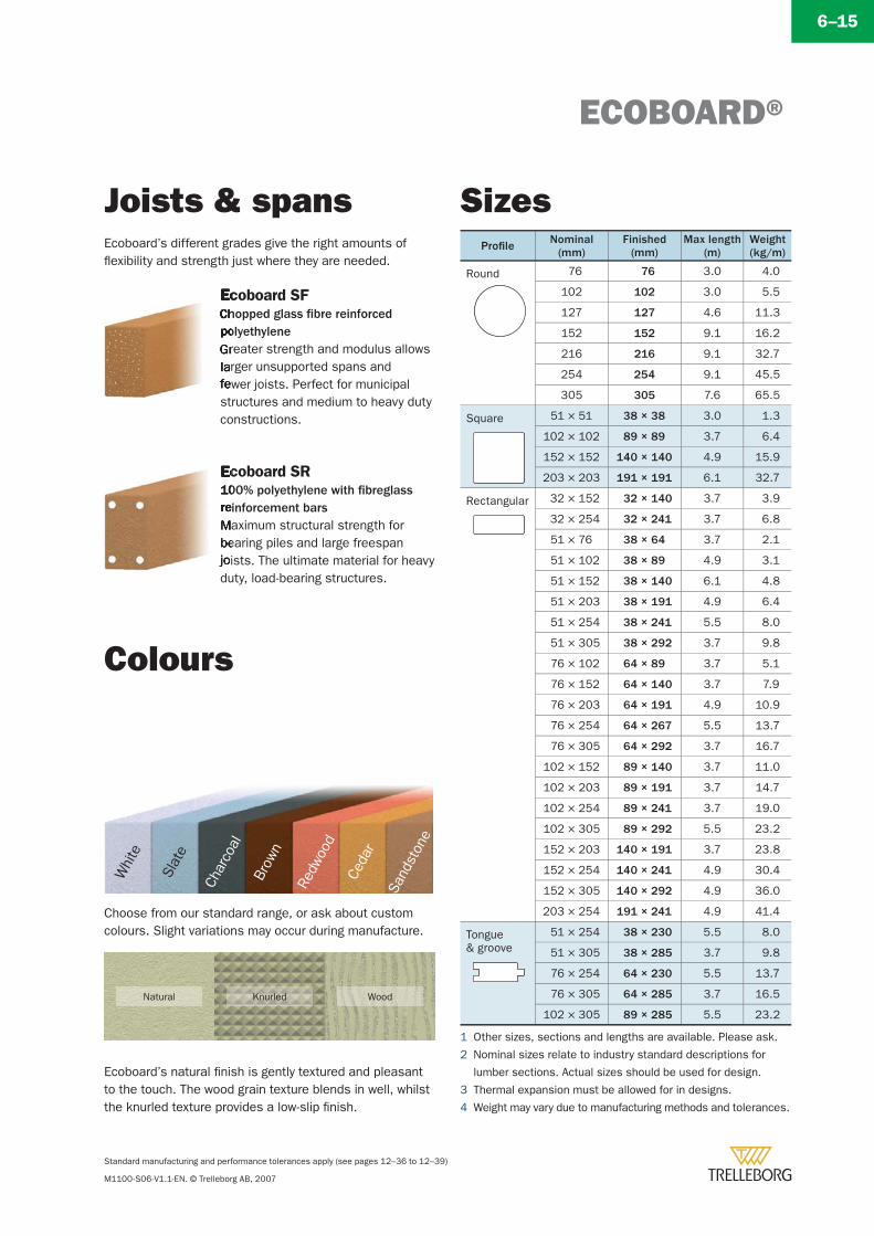
ECOBOARD®
Standard manufacturing and performance tolerances apply (see pages 12–36 to 12–39)
M1100-S06-V1.1-EN. © Trelleborg AB, 2007
6–15
Joists & spans SizesEcoboard’s different grades give the right amounts of fl exibility and strength just where they are needed.
Ecoboard SFChopped glass fi bre reinforced polyethyleneGreater strength and modulus allows larger unsupported spans and fewer joists. Perfect for municipal structures and medium to heavy duty constructions.
Ecoboard SR100% polyethylene with fi breglass reinforcement barsMaximum structural strength for bearing piles and large freespan joists. The ultimate material for heavy duty, load-bearing structures.
Colours
Whi
te
Slat
e
Char
coal
Brow
n
Redw
ood
Ceda
r
Sand
ston
e
Choose from our standard range, or ask about custom colours. Slight variations may occur during manufacture.
Ecoboard’s natural fi nish is gently textured and pleasant to the touch. The wood grain texture blends in well, whilst the knurled texture provides a low-slip fi nish.
Natural Knurled Wood
1 Other sizes, sections and lengths are available. Please ask.
2 Nominal sizes relate to industry standard descriptions for
lumber sections. Actual sizes should be used for design.
3 Thermal expansion must be allowed for in designs.
4 Weight may vary due to manufacturing methods and tolerances.
Profi le Nominal(mm)
Finished(mm)
Max length(m)
Weight(kg/m)
Round 76 76 3.0 4.0
102 102 3.0 5.5
127 127 4.6 11.3
152 152 9.1 16.2
216 216 9.1 32.7
254 254 9.1 45.5
305 305 7.6 65.5
Square 51 × 51 38 × 38 3.0 1.3
102 × 102 89 × 89 3.7 6.4
152 × 152 140 × 140 4.9 15.9
203 × 203 191 × 191 6.1 32.7
Rectangular 32 × 152 32 × 140 3.7 3.9
32 × 254 32 × 241 3.7 6.8
51 × 76 38 × 64 3.7 2.1
51 × 102 38 × 89 4.9 3.1
51 × 152 38 × 140 6.1 4.8
51 × 203 38 × 191 4.9 6.4
51 × 254 38 × 241 5.5 8.0
51 × 305 38 × 292 3.7 9.8
76 × 102 64 × 89 3.7 5.1
76 × 152 64 × 140 3.7 7.9
76 × 203 64 × 191 4.9 10.9
76 × 254 64 × 267 5.5 13.7
76 × 305 64 × 292 3.7 16.7
102 × 152 89 × 140 3.7 11.0
102 × 203 89 × 191 3.7 14.7
102 × 254 89 × 241 3.7 19.0
102 × 305 89 × 292 5.5 23.2
152 × 203 140 × 191 3.7 23.8
152 × 254 140 × 241 4.9 30.4
152 × 305 140 × 292 4.9 36.0
203 × 254 191 × 241 4.9 41.4
Tongue & groove
51 × 254 38 × 230 5.5 8.0
51 × 305 38 × 285 3.7 9.8
76 × 254 64 × 230 5.5 13.7
76 × 305 64 × 285 3.7 16.5
102 × 305 89 × 285 5.5 23.2

ECOBOARD®
Standard manufacturing and performance tolerances apply (see pages 12–36 to 12–39)
M1100-S06-V1.1-EN. © Trelleborg AB, 2007
6–16
Design fabrication
ChamferingDrilling and counterboringShapingPre-curving*
Trelleborg can supply everything from plain lengths to a factory fabricated kit of parts, fully engineered and ready for rapid site assembly. Please ask for details
�
�
�
�
* SF grades only.
Sustainability is about economic growth, social development and a healthy
environment. Within Trelleborg the ethos of sustainability involves everybody and everything we do
or make, becoming a natural part of our daily business operations.
Ecoboard is a perfect example. Made from recycled raw materials in a clean and energy effi cient factory. It is toxin-free, inert and non-polluting. Ecoboard is long lasting but even at the end of it’s useful service life it can be fully recycled and used again.
Visit www.trelleborg.com/sustainability to learn more about Trelleborg’s efforts to build a sustainable environment within a commercial world.
Sustainability
50 Year Limited Warranty for Ecoboard®
50 Year Warranty
Please refer to your local offi ce for full details of theEcoboard 50 Year Limited Warranty backed by Trelleborg.Founded in 1905, Trelleborg now operates in 40 countries, employs over 22,000 people and has annual sales of $4 billion.
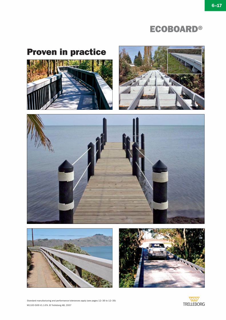
ECOBOARD®
Standard manufacturing and performance tolerances apply (see pages 12–36 to 12–39)
M1100-S06-V1.1-EN. © Trelleborg AB, 2007
6–17
Proven in practice

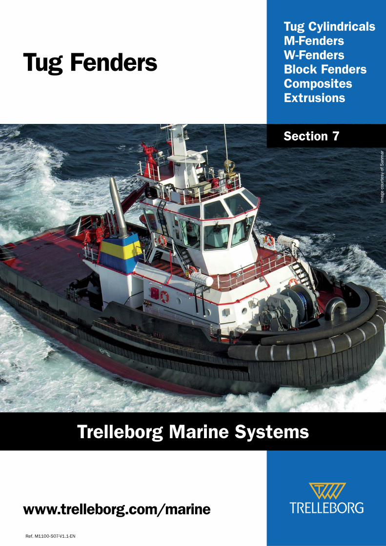
Tug CylindricalsM-FendersW-FendersBlock FendersCompositesExtrusions
Tug Fenders
Ref. M1100-S07-V1.1-EN
Section 7
www.trelleborg.com/marine
Imag
e co
urte
sy o
f San
mar
Trelleborg Marine Systems
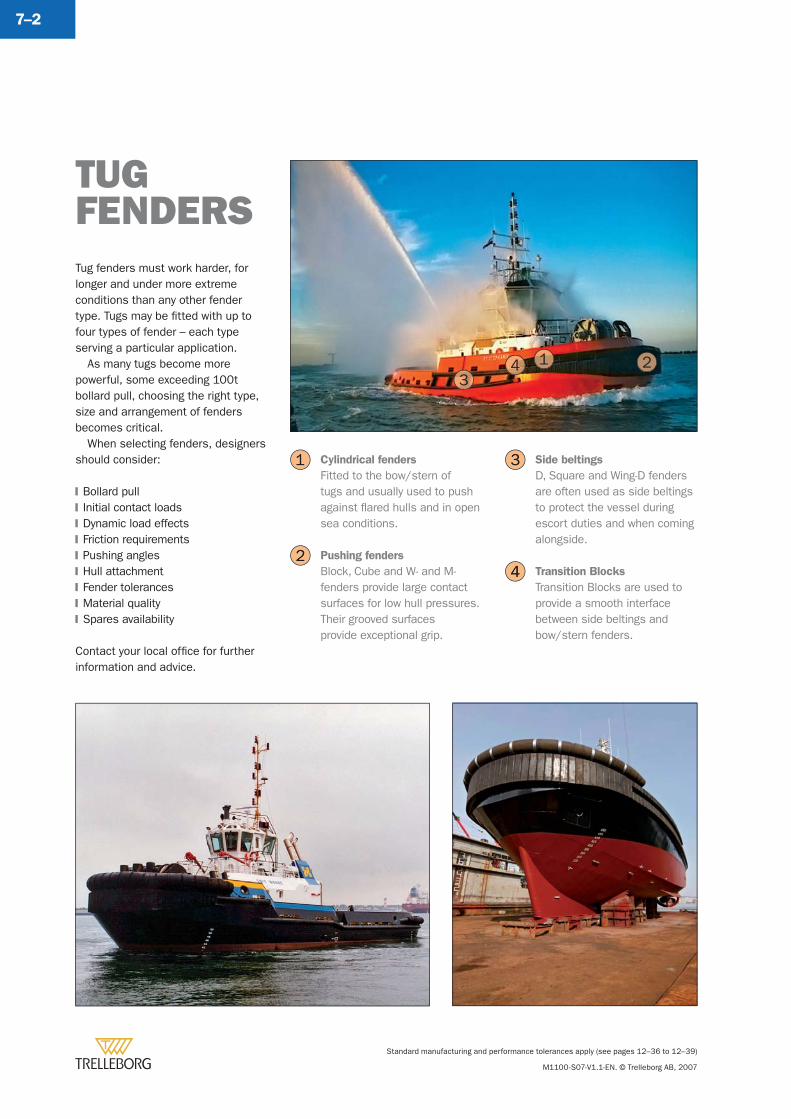
Standard manufacturing and performance tolerances apply (see pages 12–36 to 12–39)
M1100-S07-V1.1-EN. © Trelleborg AB, 2007
7–2
Tug fenders must work harder, for longer and under more extreme conditions than any other fender type. Tugs may be fi tted with up to four types of fender – each type serving a particular application.
As many tugs become more powerful, some exceeding 100t bollard pull, choosing the right type, size and arrangement of fenders becomes critical.
When selecting fenders, designers should consider:
Bollard pullInitial contact loadsDynamic load effectsFriction requirementsPushing anglesHull attachmentFender tolerancesMaterial qualitySpares availability
Contact your local offi ce for further information and advice.
�
�
�
�
�
�
�
�
�
TUGFENDERS
Cylindrical fenders
Fitted to the bow/stern of tugs and usually used to push against fl ared hulls and in open sea conditions.
Pushing fenders
Block, Cube and W- and M-fenders provide large contact surfaces for low hull pressures. Their grooved surfaces provide exceptional grip.
Side beltings
D, Square and Wing-D fenders are often used as side beltings to protect the vessel during escort duties and when coming alongside.
Transition Blocks
Transition Blocks are used to provide a smooth interface between side beltings and bow/stern fenders.
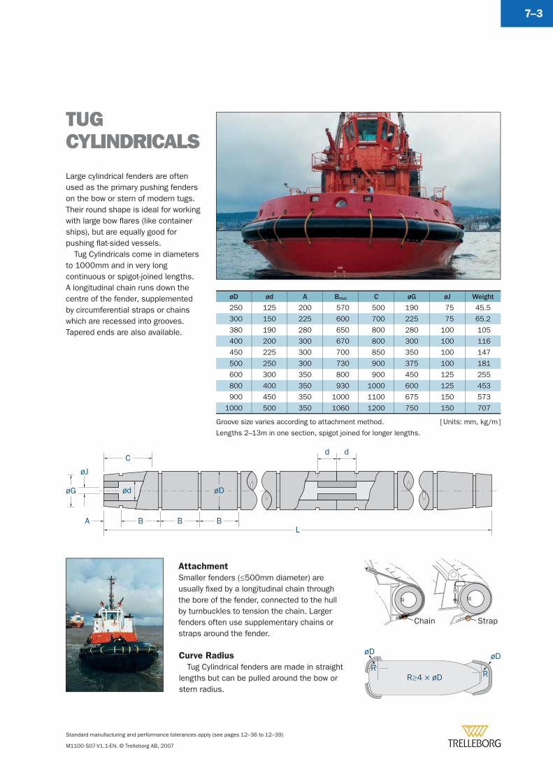
Standard manufacturing and performance tolerances apply (see pages 12–36 to 12–39)
M1100-S07-V1.1-EN. © Trelleborg AB, 2007
7–3
øD ød A Bmax C øG øJ Weight
250 125 200 570 500 190 75 45.5
300 150 225 600 700 225 75 65.2
380 190 280 650 800 280 100 105
400 200 300 670 800 300 100 116
450 225 300 700 850 350 100 147
500 250 300 730 900 375 100 181
600 300 350 800 900 450 125 255
800 400 350 930 1000 600 125 453
900 450 350 1000 1100 675 150 573
1000 500 350 1060 1200 750 150 707
Large cylindrical fenders are often used as the primary pushing fenders on the bow or stern of modern tugs. Their round shape is ideal for working with large bow fl ares (like container ships), but are equally good for pushing fl at-sided vessels.
Tug Cylindricals come in diameters to 1000mm and in very long continuous or spigot-joined lengths. A longitudinal chain runs down the centre of the fender, supplemented by circumferential straps or chains which are recessed into grooves. Tapered ends are also available.
TUG CYLINDRICALS
[ Units: mm, kg/m ]
øD
øJ
øG
C
BBBAL
ød
d d
Groove size varies according to attachment method.
Lengths 2–13m in one section, spigot joined for longer lengths.
Attachment
Smaller fenders (≤500mm diameter) are usually fi xed by a longitudinal chain through the bore of the fender, connected to the hull by turnbuckles to tension the chain. Larger fenders often use supplementary chains or straps around the fender.
Curve Radius
Tug Cylindrical fenders are made in straight lengths but can be pulled around the bow or stern radius.
R
øD
R
øD
R≥4 × øD
StrapChain
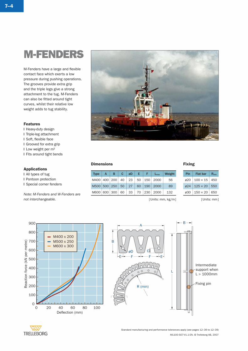
Standard manufacturing and performance tolerances apply (see pages 12–36 to 12–39)
M1100-S07-V1.1-EN. © Trelleborg AB, 2007
7–4
Type A B C øD E F Lmax Weight
M400 400 200 40 23 50 150 2000 56
M500 500 250 50 27 60 190 2000 89
M600 600 300 60 33 70 230 2000 132
[ Units: mm, kg/m ]
B
L
Intermediatesupport whenL > 1000mm
Fixing pin
A
B
øDEFFE
C
R (min)Rea
ctio
n fo
rce
(kN
per
met
re)
Deflection (mm)
0
100
200
300
400
500
600
700
800
900
0 20 40 60 80 100
M400 x 200M500 x 250M600 x 300
M-FENDERSM-Fenders have a large and fl exible contact face which exerts a low pressure during pushing operations. The grooves provide extra grip and the triple legs give a strong attachment to the tug. M-Fenders can also be fi tted around tight curves, whilst their relative low weight adds to tug stability.
Features
Heavy-duty designTriple-leg attachmentSoft, fl exible faceGrooved for extra gripLow weight per m2Fits around tight bends
Applications
All types of tugPontoon protectionSpecial corner fenders
Note: M-Fenders and W-Fenders are not interchangeable.
�
�
�
�
�
�
�
�
�
Pin Flat bar Rmin
ø20 100 × 15 450
ø24 125 × 20 550
ø30 150 × 20 650
[ Units: mm ]
Dimensions Fixing
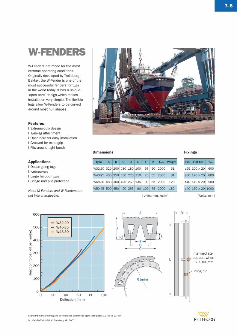
Standard manufacturing and performance tolerances apply (see pages 12–36 to 12–39)
M1100-S07-V1.1-EN. © Trelleborg AB, 2007
7–5
W-FENDERSW-Fenders are made for the most extreme operating conditions. Originally developed by Trelleborg Bakker, the W-Fender is one of the most successful fenders for tugs in the world today. It has a unique ‘open bore’ design which makes installation very simple. The fl exible legs allow W-Fenders to be curved around most hull shapes.
Features
Extreme-duty designTwin-leg attachmentOpen bore for easy installationGrooved for extra gripFits around tight bends
Applications
Ocean-going tugsIcebreakersLarge harbour tugsBridge and pile protection
Note: M-Fenders and W-Fenders are not interchangeable.
�
�
�
�
�
�
�
�
�
Type A B C D E F K Lmax Weight
W32-20 320 200 280 180 100 67 50 2000 51
W40-25 400 250 350 220 110 75 55 2000 81
W48-30 480 300 426 269 135 90 65 2000 120
W50-45 500 450 420 255 90 100 75 2000 180
A
B
R (min)
EDC
K F
Rea
ctio
n fo
rce
(kN
per
met
re)
Deflection (mm)
0
100
200
300
400
500
600
0 20 40 60 80 100
W32-20W40-25W48-30
B
L
Intermediatesupport whenL > 1000mm
Fixing pin
Pin Flat bar Rmin
ø25 100 × 20 600
ø30 120 × 20 800
ø40 140 × 20 900
ø40 150 × 20 1000
Dimensions Fixings
[ Units: mm, kg/m ] [ Units: mm ]
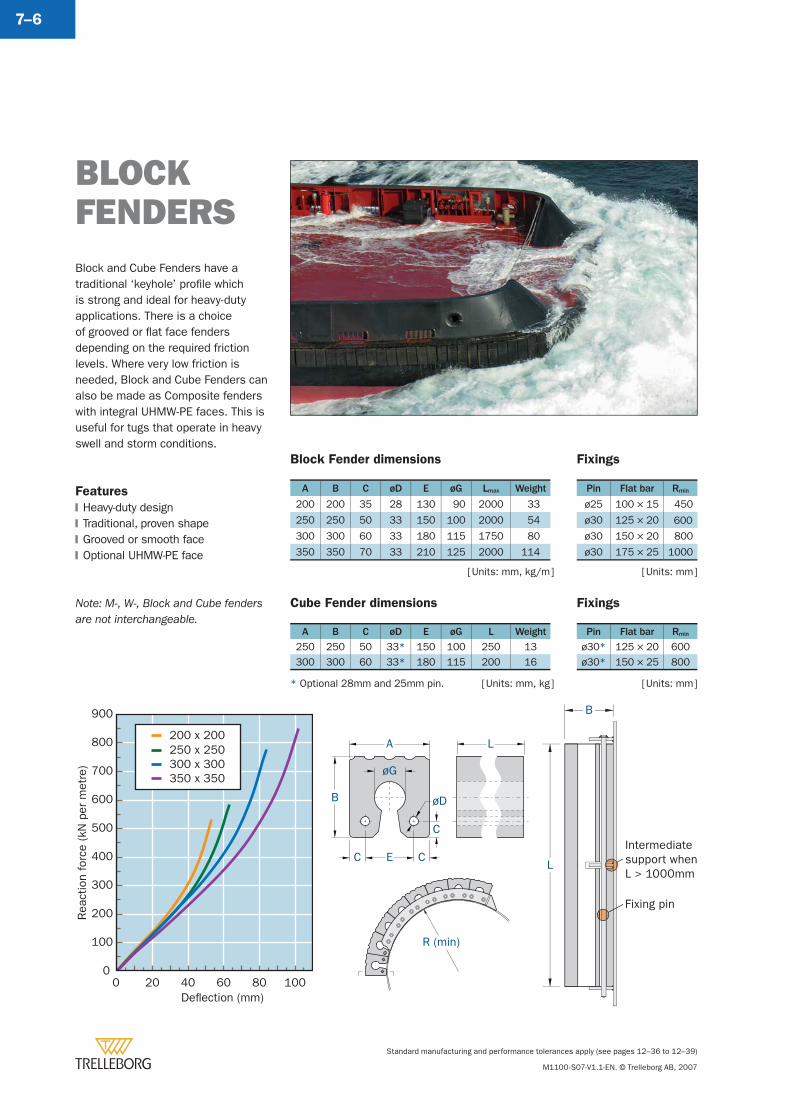
Standard manufacturing and performance tolerances apply (see pages 12–36 to 12–39)
M1100-S07-V1.1-EN. © Trelleborg AB, 2007
7–6
Block Fender dimensions
A B C øD E øG Lmax Weight
200 200 35 28 130 90 2000 33
250 250 50 33 150 100 2000 54
300 300 60 33 180 115 1750 80
350 350 70 33 210 125 2000 114
Cube Fender dimensions
A B C øD E øG L Weight
250 250 50 33* 150 100 250 13300 300 60 33* 180 115 200 16
[ Units: mm ]
BLOCK FENDERSBlock and Cube Fenders have a traditional ‘keyhole’ profi le which is strong and ideal for heavy-duty applications. There is a choice of grooved or fl at face fenders depending on the required friction levels. Where very low friction is needed, Block and Cube Fenders can also be made as Composite fenders with integral UHMW-PE faces. This is useful for tugs that operate in heavy swell and storm conditions.
Features
Heavy-duty designTraditional, proven shapeGrooved or smooth faceOptional UHMW-PE face
Note: M-, W-, Block and Cube fenders are not interchangeable.
�
�
�
�
B
A
C
EC
øG
øD
L
C
R (min)
B
L
Intermediatesupport whenL > 1000mm
Fixing pin
[ Units: mm ]
Rea
ctio
n fo
rce
(kN
per
met
re)
Deflection (mm)
0
100
200
300
400
500
600
700
800
900
0 20 40 60 80 100
200 x 200250 x 250300 x 300350 x 350
* Optional 28mm and 25mm pin.
[ Units: mm, kg/m ]
Fixings
Pin Flat bar Rmin
ø30* 125 × 20 600ø30* 150 × 25 800
Fixings
Pin Flat bar Rmin
ø25 100 × 15 450
ø30 125 × 20 600
ø30 150 × 20 800
ø30 175 × 25 1000
[ Units: mm, kg ]
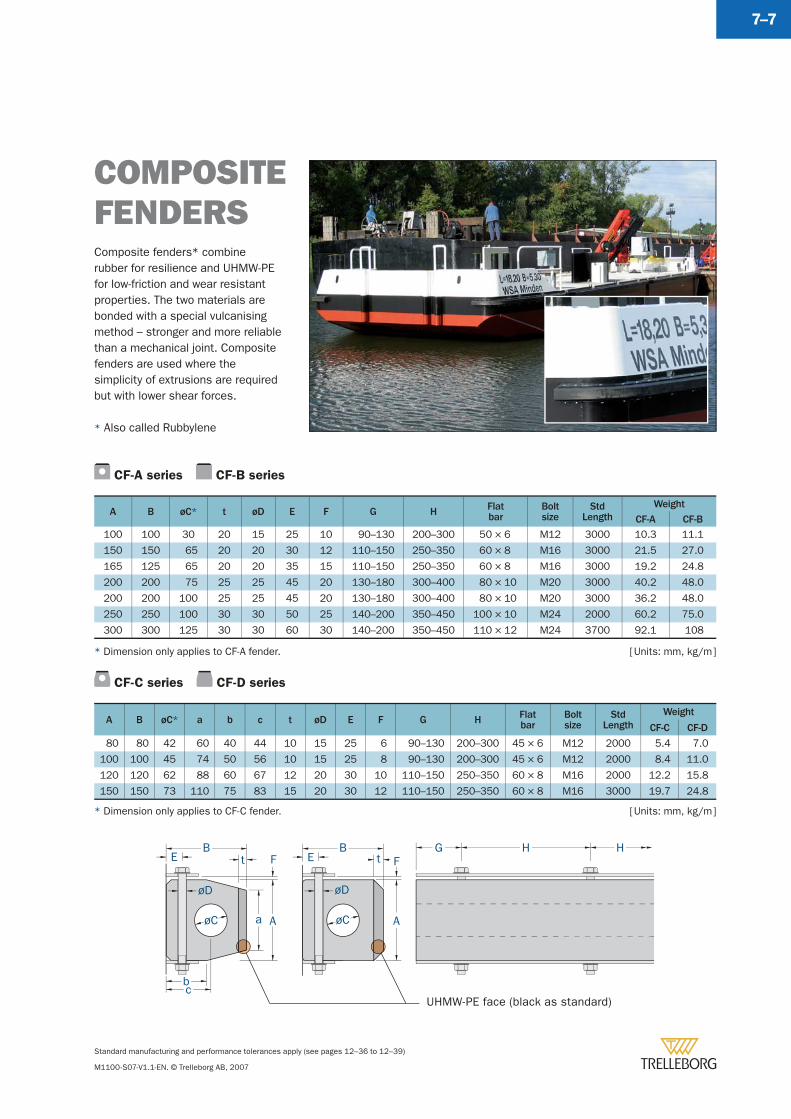
Standard manufacturing and performance tolerances apply (see pages 12–36 to 12–39)
M1100-S07-V1.1-EN. © Trelleborg AB, 2007
7–7
Composite fenders* combine rubber for resilience and UHMW-PE for low-friction and wear resistant properties. The two materials are bonded with a special vulcanising method – stronger and more reliable than a mechanical joint. Composite fenders are used where the simplicity of extrusions are required but with lower shear forces.
* Also called Rubbylene
COMPOSITEFENDERS
CF-A series CF-B series
A B øC* t øD E F G H Flatbar
Boltsize
StdLength
Weight
CF-A CF-B
100 100 30 20 15 25 10 90–130 200–300 50 × 6 M12 3000 10.3 11.1
150 150 65 20 20 30 12 110–150 250–350 60 × 8 M16 3000 21.5 27.0
165 125 65 20 20 35 15 110–150 250–350 60 × 8 M16 3000 19.2 24.8
200 200 75 25 25 45 20 130–180 300–400 80 × 10 M20 3000 40.2 48.0
200 200 100 25 25 45 20 130–180 300–400 80 × 10 M20 3000 36.2 48.0
250 250 100 30 30 50 25 140–200 350–450 100 × 10 M24 2000 60.2 75.0
300 300 125 30 30 60 30 140–200 350–450 110 × 12 M24 3700 92.1 108
[ Units: mm, kg/m ]* Dimension only applies to CF-A fender.
CF-C series CF-D series
A B øC* a b c t øD E F G H Flatbar
Boltsize
StdLength
Weight
CF-C CF-D
80 80 42 60 40 44 10 15 25 6 90–130 200–300 45 × 6 M12 2000 5.4 7.0
100 100 45 74 50 56 10 15 25 8 90–130 200–300 45 × 6 M12 2000 8.4 11.0
120 120 62 88 60 67 12 20 30 10 110–150 250–350 60 × 8 M16 2000 12.2 15.8
150 150 73 110 75 83 15 20 30 12 110–150 250–350 60 × 8 M16 3000 19.7 24.8
[ Units: mm, kg/m ]* Dimension only applies to CF-C fender.
F
A
t
øC
BE
øD
G H HBE
øD
øC
F
Aa
b
t
cUHMW-PE face (black as standard)
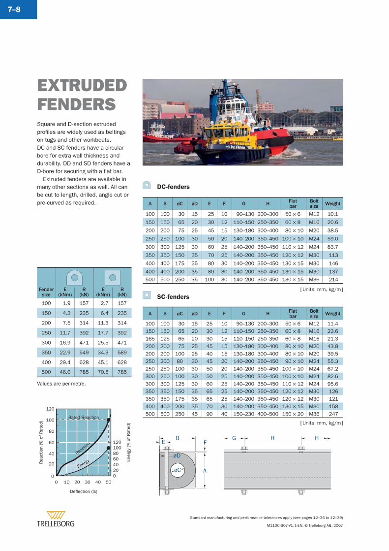
Standard manufacturing and performance tolerances apply (see pages 12–36 to 12–39)
M1100-S07-V1.1-EN. © Trelleborg AB, 2007
7–8
Deflection (%)
0 10 20 30 40 50
Rea
ctio
n (%
of R
ated
)
20
40
60
80
100
120
0
Ener
gy (%
of R
ated
)
0
4020
6080100120
Reacti
on
Energy
Rated Reaction
Fendersize
E(kNm)
R(kN)
E(kNm)
R(kN)
100 1.9 157 2.7 157
150 4.2 235 6.4 235
200 7.5 314 11.3 314
250 11.7 392 17.7 392
300 16.9 471 25.5 471
350 22.9 549 34.3 589
400 29.4 628 45.1 628
500 46.0 785 70.5 785
Values are per metre.
DC-fenders
A B øC øD E F G H Flatbar
Boltsize Weight
100 100 30 15 25 10 90–130 200–300 50 × 6 M12 10.1
150 150 65 20 30 12 110–150 250–350 60 × 8 M16 20.6
200 200 75 25 45 15 130–180 300–400 80 × 10 M20 38.5
250 250 100 30 50 20 140–200 350–450 100 × 10 M24 59.0
300 300 125 30 60 25 140–200 350–450 110 × 12 M24 83.7
350 350 150 35 70 25 140–200 350–450 120 × 12 M30 113
400 400 175 35 80 30 140–200 350–450 130 × 15 M30 146
400 400 200 35 80 30 140–200 350–450 130 × 15 M30 137
500 500 250 35 100 30 140–200 350–450 130 × 15 M36 214
SC-fenders
A B øC øD E F G H Flatbar
Boltsize Weight
100 100 30 15 25 10 90–130 200–300 50 × 6 M12 11.4150 150 65 20 30 12 110–150 250–350 60 × 8 M16 23.6165 125 65 20 30 15 110–150 250–350 60 × 8 M16 21.3200 200 75 25 45 15 130–180 300–400 80 × 10 M20 43.8200 200 100 25 40 15 130–180 300–400 80 × 10 M20 39.5250 200 80 30 45 20 140–200 350–450 90 × 10 M24 55.3250 250 100 30 50 20 140–200 350–450 100 × 10 M24 67.2300 250 100 30 50 25 140–200 350–450 100 × 10 M24 82.6300 300 125 30 60 25 140–200 350–450 110 × 12 M24 95.6350 350 150 35 65 25 140–200 350–450 120 × 12 M30 126350 350 175 35 65 25 140–200 350–450 120 × 12 M30 121400 400 200 35 70 30 140–200 350–450 130 × 15 M30 158500 500 250 45 90 40 150–230 400–500 150 × 20 M36 247
Square and D-section extruded profi les are widely used as beltings on tugs and other workboats.DC and SC fenders have a circular bore for extra wall thickness and durability. DD and SD fenders have a D-bore for securing with a fl at bar.
Extruded fenders are available in many other sections as well. All can be cut to length, drilled, angle cut or pre-curved as required.
EXTRUDED FENDERS
G H HF
AøC
BE
øD
[ Units: mm, kg/m ]
[ Units: mm, kg/m ]
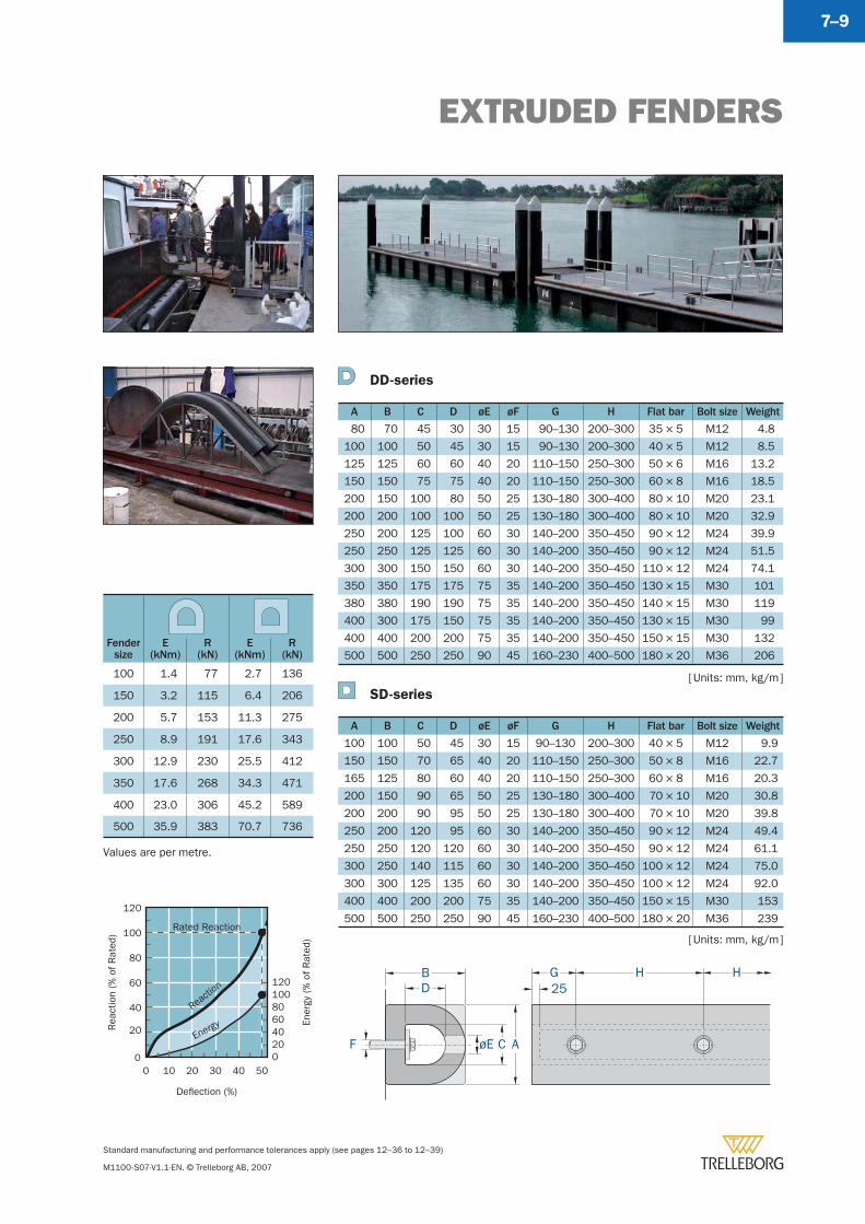
EXTRUDED FENDERS
Standard manufacturing and performance tolerances apply (see pages 12–36 to 12–39)
M1100-S07-V1.1-EN. © Trelleborg AB, 2007
7–9
DD-series
A B C D øE øF G H Flat bar Bolt size Weight
80 70 45 30 30 15 90–130 200–300 35 × 5 M12 4.8
100 100 50 45 30 15 90–130 200–300 40 × 5 M12 8.5
125 125 60 60 40 20 110–150 250–300 50 × 6 M16 13.2
150 150 75 75 40 20 110–150 250–300 60 × 8 M16 18.5
200 150 100 80 50 25 130–180 300–400 80 × 10 M20 23.1
200 200 100 100 50 25 130–180 300–400 80 × 10 M20 32.9
250 200 125 100 60 30 140–200 350–450 90 × 12 M24 39.9
250 250 125 125 60 30 140–200 350–450 90 × 12 M24 51.5
300 300 150 150 60 30 140–200 350–450 110 × 12 M24 74.1
350 350 175 175 75 35 140–200 350–450 130 × 15 M30 101
380 380 190 190 75 35 140–200 350–450 140 × 15 M30 119
400 300 175 150 75 35 140–200 350–450 130 × 15 M30 99
400 400 200 200 75 35 140–200 350–450 150 × 15 M30 132
500 500 250 250 90 45 160–230 400–500 180 × 20 M36 206
SD-series
A B C D øE øF G H Flat bar Bolt size Weight
100 100 50 45 30 15 90–130 200–300 40 × 5 M12 9.9
150 150 70 65 40 20 110–150 250–300 50 × 8 M16 22.7
165 125 80 60 40 20 110–150 250–300 60 × 8 M16 20.3
200 150 90 65 50 25 130–180 300–400 70 × 10 M20 30.8
200 200 90 95 50 25 130–180 300–400 70 × 10 M20 39.8
250 200 120 95 60 30 140–200 350–450 90 × 12 M24 49.4
250 250 120 120 60 30 140–200 350–450 90 × 12 M24 61.1
300 250 140 115 60 30 140–200 350–450 100 × 12 M24 75.0
300 300 125 135 60 30 140–200 350–450 100 × 12 M24 92.0
400 400 200 200 75 35 140–200 350–450 150 × 15 M30 153
500 500 250 250 90 45 160–230 400–500 180 × 20 M36 239
[ Units: mm, kg/m ]
[ Units: mm, kg/m ]
Fendersize
E(kNm)
R(kN)
E(kNm)
R(kN)
100 1.4 77 2.7 136
150 3.2 115 6.4 206
200 5.7 153 11.3 275
250 8.9 191 17.6 343
300 12.9 230 25.5 412
350 17.6 268 34.3 471
400 23.0 306 45.2 589
500 35.9 383 70.7 736
Values are per metre.
ACøEF
G H HBD 25
Deflection (%)
0 10 20 30 40 50
Rea
ctio
n (%
of R
ated
)
20
40
60
80
100
120
0
Ener
gy (%
of R
ated
)
0
4020
6080100120
Reacti
on
Energy
Rated Reaction
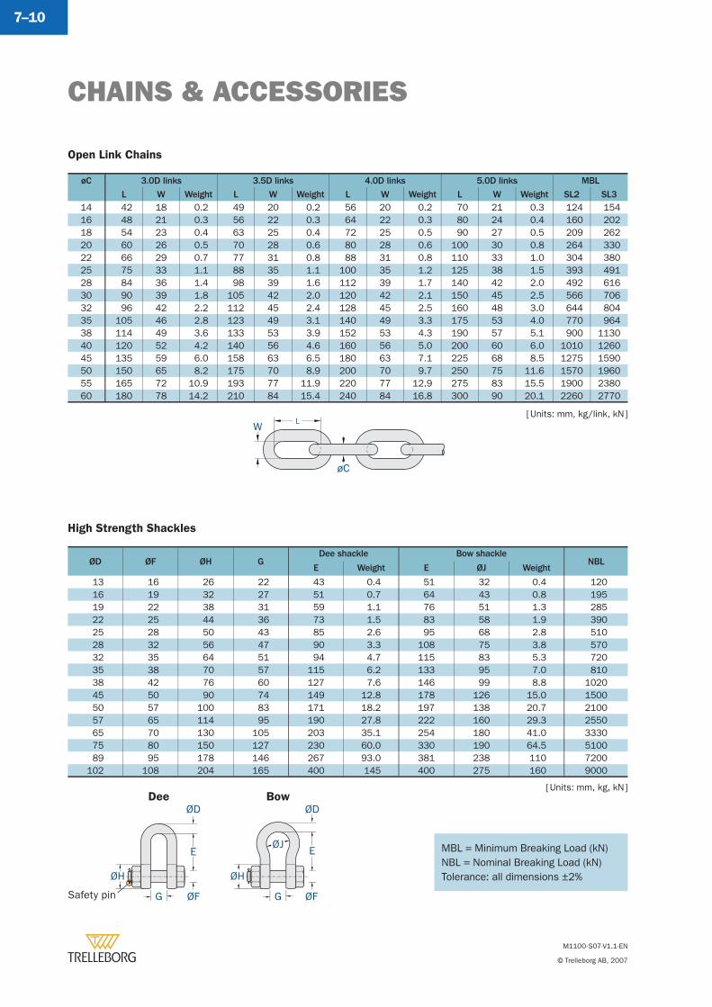
CHAINS & ACCESSORIES
M1100-S07-V1.1-EN
© Trelleborg AB, 2007
7–10
Open Link Chains
øC 3.0D links 3.5D links 4.0D links 5.0D links MBL
L W Weight L W Weight L W Weight L W Weight SL2 SL314 42 18 0.2 49 20 0.2 56 20 0.2 70 21 0.3 124 15416 48 21 0.3 56 22 0.3 64 22 0.3 80 24 0.4 160 20218 54 23 0.4 63 25 0.4 72 25 0.5 90 27 0.5 209 26220 60 26 0.5 70 28 0.6 80 28 0.6 100 30 0.8 264 33022 66 29 0.7 77 31 0.8 88 31 0.8 110 33 1.0 304 38025 75 33 1.1 88 35 1.1 100 35 1.2 125 38 1.5 393 49128 84 36 1.4 98 39 1.6 112 39 1.7 140 42 2.0 492 61630 90 39 1.8 105 42 2.0 120 42 2.1 150 45 2.5 566 70632 96 42 2.2 112 45 2.4 128 45 2.5 160 48 3.0 644 80435 105 46 2.8 123 49 3.1 140 49 3.3 175 53 4.0 770 96438 114 49 3.6 133 53 3.9 152 53 4.3 190 57 5.1 900 113040 120 52 4.2 140 56 4.6 160 56 5.0 200 60 6.0 1010 126045 135 59 6.0 158 63 6.5 180 63 7.1 225 68 8.5 1275 159050 150 65 8.2 175 70 8.9 200 70 9.7 250 75 11.6 1570 196055 165 72 10.9 193 77 11.9 220 77 12.9 275 83 15.5 1900 238060 180 78 14.2 210 84 15.4 240 84 16.8 300 90 20.1 2260 2770
[ Units: mm, kg/link, kN ]W
L
øC
MBL = Minimum Breaking Load (kN)NBL = Nominal Breaking Load (kN)Tolerance: all dimensions ±2%
High Strength Shackles
ØD ØF ØH GDee shackle Bow shackle
NBLE Weight E ØJ Weight
13 16 26 22 43 0.4 51 32 0.4 120 16 19 32 27 51 0.7 64 43 0.8 195 19 22 38 31 59 1.1 76 51 1.3 285 22 25 44 36 73 1.5 83 58 1.9 390 25 28 50 43 85 2.6 95 68 2.8 510 28 32 56 47 90 3.3 108 75 3.8 570 32 35 64 51 94 4.7 115 83 5.3 720 35 38 70 57 115 6.2 133 95 7.0 810 38 42 76 60 127 7.6 146 99 8.8 1020 45 50 90 74 149 12.8 178 126 15.0 1500 50 57 100 83 171 18.2 197 138 20.7 2100 57 65 114 95 190 27.8 222 160 29.3 2550 65 70 130 105 203 35.1 254 180 41.0 3330 75 80 150 127 230 60.0 330 190 64.5 5100 89 95 178 146 267 93.0 381 238 110 7200102 108 204 165 400 145 400 275 160 9000
ØD
E
ØF
ØH
G
ØJ
ØH
ØD
E
ØFGSafety pin
Dee Bow[ Units: mm, kg, kN ]
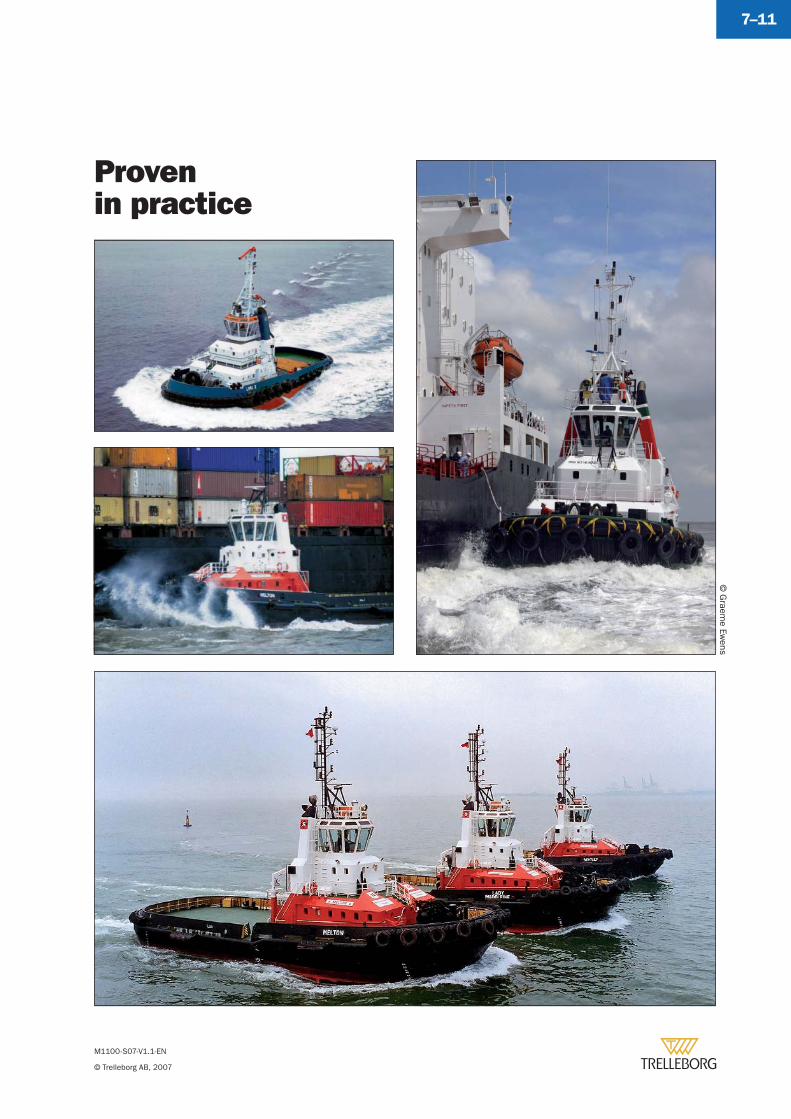
M1100-S07-V1.1-EN
© Trelleborg AB, 2007
7–11
Provenin practice
© G
raeme Ew
ens
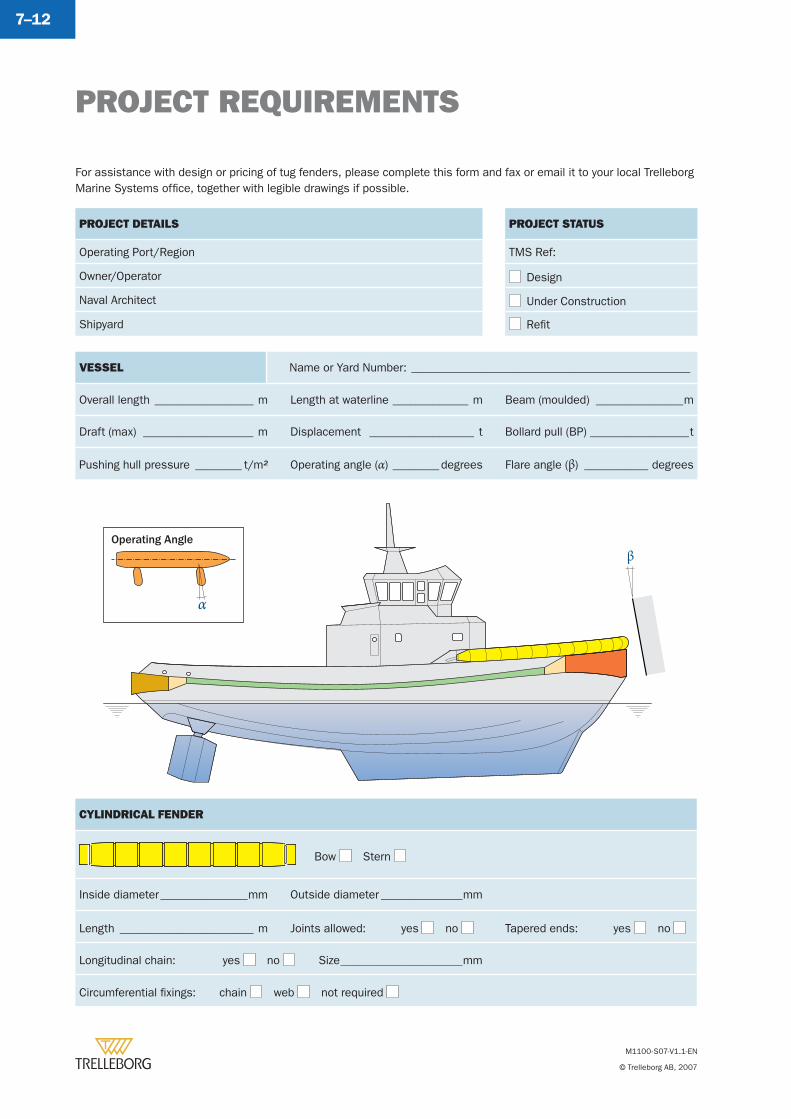
PROJECT REQUIREMENTS
M1100-S07-V1.1-EN
© Trelleborg AB, 2007
7–12
β
VESSEL Name or Yard Number: ________________________________________________
Overall length _________________ m Length at waterline _____________ m Beam (moulded) _______________m
Draft (max) ___________________ m Displacement __________________ t Bollard pull (BP) _________________t
Pushing hull pressure ________ t/m2 Operating angle (α) ________degrees Flare angle (β) ___________ degrees
CYLINDRICAL FENDER
Bow Stern
Inside diameter _______________mm Outside diameter ______________mm
Length _______________________ m Joints allowed: yes no Tapered ends: yes no
Longitudinal chain: yes no Size _____________________mm
Circumferential fi xings: chain web not required
For assistance with design or pricing of tug fenders, please complete this form and fax or email it to your local Trelleborg Marine Systems offi ce, together with legible drawings if possible.
PROJECT DETAILS
Operating Port/Region
Owner/Operator
Naval Architect
Shipyard
PROJECT STATUS
TMS Ref:
Design
Under Construction
Refi t
α
Operating Angle
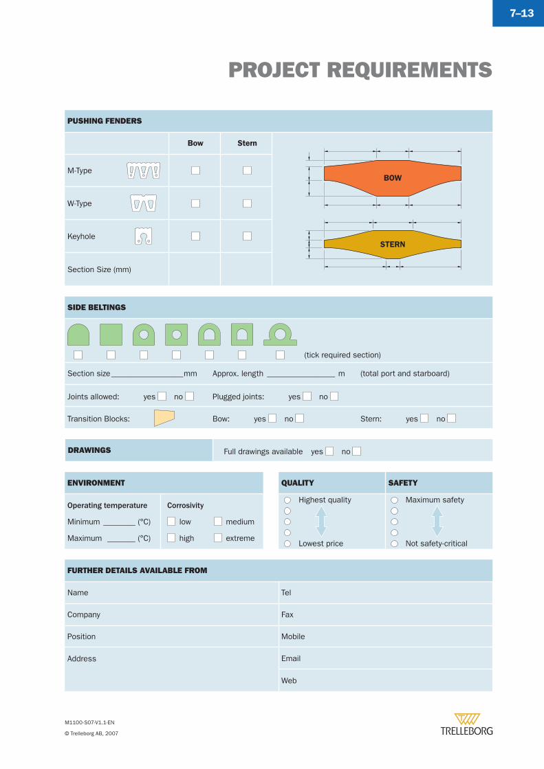
PROJECT REQUIREMENTS
M1100-S07-V1.1-EN
© Trelleborg AB, 2007
7–13
PUSHING FENDERS
Bow Stern
BOW
STERN
M-Type
W-Type
Keyhole
Section Size (mm)
DRAWINGS Full drawings available yes no
SIDE BELTINGS
(tick required section)
Section size __________________mm Approx. length _________________ m (total port and starboard)
Joints allowed: yes no Plugged joints: yes no
Transition Blocks: Bow: yes no Stern: yes no
FURTHER DETAILS AVAILABLE FROM
Name Tel
Company Fax
Position Mobile
Address Email
Web
QUALITY SAFETY
Highest quality Maximum safety
Lowest price Not safety-critical
ENVIRONMENT
Operating temperature
Minimum ________ (°C)
Maximum _______ (°C)
Corrosivity
low medium
high extreme

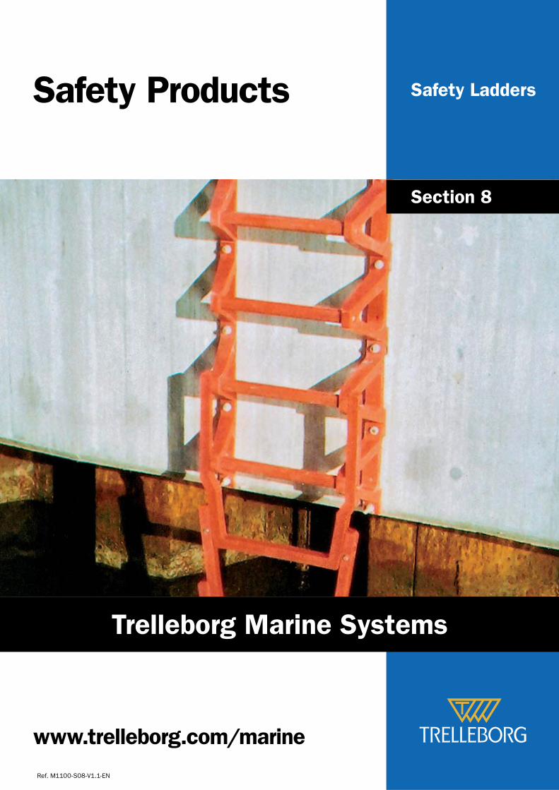
Safety LaddersSafety Products
Ref. M1100-S08-V1.1-EN
Section 8
www.trelleborg.com/marine
Trelleborg Marine Systems
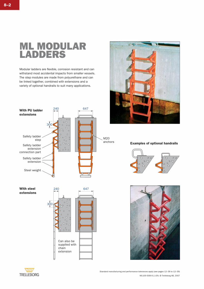
Standard manufacturing and performance tolerances apply (see pages 12–36 to 12–39)
M1100-S08-V1.1-EN. © Trelleborg AB, 2007
8–2
Modular ladders are fl exible, corrosion resistant and can withstand most accidental impacts from smaller vessels. The step modules are made from polyurethane and can be linked together, combined with extensions and a variety of optional handrails to suit many applications.
ML MODULARLADDERS
647240
Safety ladderstep
Safety ladderextension
connection part
Safety ladderextension
Steel weight
300
M20anchors
Can also besupplied withchainextension
647240
300
With PU ladder
extensions
With steel
extensions
Examples of optional handrails
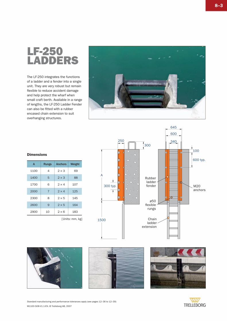
Standard manufacturing and performance tolerances apply (see pages 12–36 to 12–39)
M1100-S08-V1.1-EN. © Trelleborg AB, 2007
8–3
The LF-250 integrates the functions of a ladder and a fender into a single unit. They are very robust but remain fl exible to reduce accident damage and help protect the wharf when small craft berth. Available in a range of lengths, the LF-250 Ladder Fender can also be fi tted with a rubber encased chain extension to suit overhanging structures.
LF-250LADDERS
645
340250
100
600 typ.
A
1500
300 typ.
300
600
ø50flexible
rungs
M20anchors
Rubberladderfender
Chainladder
extension
Dimensions
A Rungs Anchors Weight
1100 4 2 × 3 69
1400 5 2 × 3 88
1700 6 2 × 4 107
2000 7 2 × 4 125
2300 8 2 × 5 145
2600 9 2 × 5 164
2900 10 2 × 6 183
[ Units: mm, kg]

Fender PanelsChainsShacklesBracketsNC3 AnchorsEC2 AnchorsFixing Bolts
Accessories
Ref. M1100-S09-V1.1-EN
Section 9
www.trelleborg.com/marine
Trelleborg Marine Systems
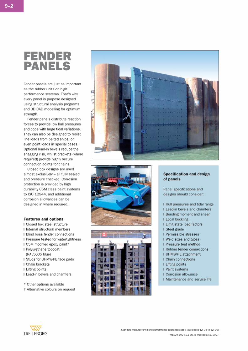
Standard manufacturing and performance tolerances apply (see pages 12–36 to 12–39)
M1100-S09-V1.1-EN. © Trelleborg AB, 2007
9–2
Fender panels are just as important as the rubber units on high performance systems. That’s why every panel is purpose designed using structural analysis programs and 3D CAD modelling for optimum strength.
Fender panels distribute reaction forces to provide low hull pressures and cope with large tidal variations. They can also be designed to resist line loads from belted ships, or even point loads in special cases. Optional lead-in bevels reduce the snagging risk, whilst brackets (where required) provide highly secure connection points for chains.
Closed box designs are used almost exclusively – all fully sealed and pressure checked. Corrosion protection is provided by high durability C5M class paint systems to ISO 12944, and additional corrosion allowances can be designed in where required.
Features and options
Closed box steel structureInternal structural membersBlind boss fender connectionsPressure tested for watertightnessC5M modifi ed epoxy paint*Polyurethane topcoat †
(RAL5005 blue)Studs for UHMW-PE face padsChain bracketsLifting pointsLead-in bevels and chamfers
* Other options available† Alternative colours on request
�
�
�
�
�
�
�
�
�
�
FENDERPANELS
Specifi cation and design
of panels
Panel specifi cations and designs should consider:
Hull pressures and tidal rangeLead-in bevels and chamfersBending moment and shearLocal bucklingLimit state load factorsSteel gradePermissible stressesWeld sizes and typesPressure test methodRubber fender connectionsUHMW-PE attachmentChain connectionsLifting pointsPaint systemsCorrosion allowanceMaintenance and service life
�
�
�
�
�
�
�
�
�
�
�
�
�
�
�
�
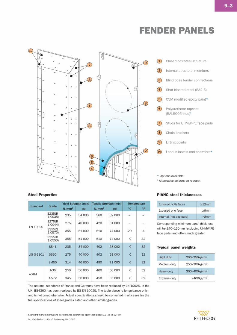
FENDER PANELS
Standard manufacturing and performance tolerances apply (see pages 12–36 to 12–39)
M1100-S09-V1.1-EN. © Trelleborg AB, 2007
9–3
The national standards of France and Germany have been replaced by EN 10025. In the
UK, BS4360 has been replaced by BS EN 10025. The table above is for guidance only
and is not comprehensive. Actual specifi cations should be consulted in all cases for the
full specifi cations of steel grades listed and other similar grades.
3
4
Closed box steel structure
Internal structural members
Blind boss fender connections
Shot blasted steel (SA2.5)
C5M modifi ed epoxy paint*
Polyurethane topcoat (RAL5005 blue)†
Studs for UHMW-PE face pads
Chain brackets
Lifting points
Lead-in bevels and chamfers*
1
2
5
6
7
8
PIANC steel thicknesses
Exposed both faces ≥ 12mm
Exposed one face ≥ 9mm
Internal (not exposed) ≥ 8mm
Corresponding minimum panel thickness
will be 140–160mm (excluding UHMW-PE
face pads) and often much greater.
Typical panel weights
Light duty 200–250kg/m2
Medium duty 250–300kg/m2
Heavy duty 300–400kg/m2
Extreme duty ≥400kg/m2
10
9
* Options available† Alternative colours on request
9
6
10
5
4
2
8
8
31
7
Steel Properties
Standard GradeYield Strength (min) Tensile Strength (min) Temperature
N/mm² psi N/mm² psi °C °F
EN 10025
S235JR(1.0038) 235 34 000 360 52 000 – –
S275JR(1.0044) 275 40 000 420 61 000 – –
S355J2(1.0570) 355 51 000 510 74 000 -20 -4
S355J0(1.0553) 355 51 000 510 74 000 0 32
JIS G-3101
SS41 235 34 000 402 58 000 0 32
SS50 275 40 000 402 58 000 0 32
SM50 314 46 000 490 71 000 0 32
ASTMA-36 250 36 000 400 58 000 0 32
A-572 345 50 000 450 65 000 0 32
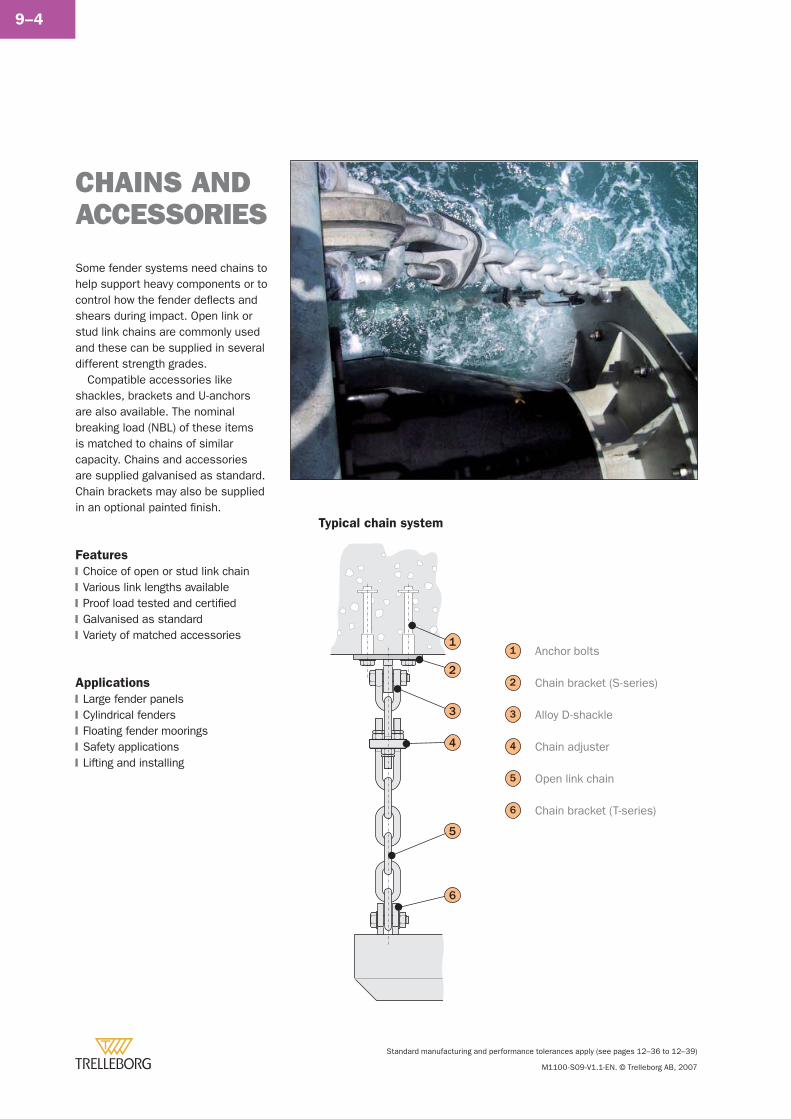
Standard manufacturing and performance tolerances apply (see pages 12–36 to 12–39)
M1100-S09-V1.1-EN. © Trelleborg AB, 2007
9–4
Some fender systems need chains to help support heavy components or to control how the fender defl ects and shears during impact. Open link or stud link chains are commonly used and these can be supplied in several different strength grades.
Compatible accessories like shackles, brackets and U-anchors are also available. The nominal breaking load (NBL) of these items is matched to chains of similar capacity. Chains and accessories are supplied galvanised as standard. Chain brackets may also be supplied in an optional painted fi nish.
Features
Choice of open or stud link chainVarious link lengths availableProof load tested and certifi edGalvanised as standardVariety of matched accessories
Applications
Large fender panelsCylindrical fendersFloating fender mooringsSafety applicationsLifting and installing
�
�
�
�
�
�
�
�
�
�
CHAINS ANDACCESSORIES
3
4
Anchor bolts
Chain bracket (S-series)
Alloy D-shackle
Chain adjuster
Open link chain
Chain bracket (T-series)
1
2
5
6
Typical chain system
5
1
3
2
4
6
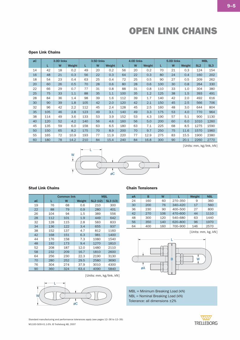
OPEN LINK CHAINS
Standard manufacturing and performance tolerances apply (see pages 12–36 to 12–39)
M1100-S09-V1.1-EN. © Trelleborg AB, 2007
9–5
Open Link Chains
øC 3.0D links 3.5D links 4.0D links 5.0D links MBL
L W Weight L W Weight L W Weight L W Weight SL2 SL3
14 42 18 0.2 49 20 0.2 56 20 0.2 70 21 0.3 124 15416 48 21 0.3 56 22 0.3 64 22 0.3 80 24 0.4 160 20218 54 23 0.4 63 25 0.4 72 25 0.5 90 27 0.5 209 26220 60 26 0.5 70 28 0.6 80 28 0.6 100 30 0.8 264 33022 66 29 0.7 77 31 0.8 88 31 0.8 110 33 1.0 304 38025 75 33 1.1 88 35 1.1 100 35 1.2 125 38 1.5 393 49128 84 36 1.4 98 39 1.6 112 39 1.7 140 42 2.0 492 61630 90 39 1.8 105 42 2.0 120 42 2.1 150 45 2.5 566 70632 96 42 2.2 112 45 2.4 128 45 2.5 160 48 3.0 644 80435 105 46 2.8 123 49 3.1 140 49 3.3 175 53 4.0 770 96438 114 49 3.6 133 53 3.9 152 53 4.3 190 57 5.1 900 113040 120 52 4.2 140 56 4.6 160 56 5.0 200 60 6.0 1010 126045 135 59 6.0 158 63 6.5 180 63 7.1 225 68 8.5 1275 159050 150 65 8.2 175 70 8.9 200 70 9.7 250 75 11.6 1570 196055 165 72 10.9 193 77 11.9 220 77 12.9 275 83 15.5 1900 238060 180 78 14.2 210 84 15.4 240 84 16.8 300 90 20.1 2260 2770
Stud Link Chains
Common link MBLøC L W Weight SL2 (U2) SL3 (U3)19 76 68 0.6 210 30022 88 79 0.9 280 40126 104 94 1.5 389 55628 112 101 1.9 449 64232 128 115 2.8 583 83334 136 122 3.4 655 93738 152 137 4.7 812 116042 168 151 6.3 981 140044 176 158 7.3 1080 154048 192 173 9.4 1270 181052 208 187 12.0 1480 211058 232 209 16.7 1810 260064 256 230 22.3 2190 313070 280 252 29.5 2580 369076 304 274 37.9 3010 430090 360 324 63.4 4090 5840
Chain Tensioners
øA B W L Weight NBL24 160 60 270–350 9 36030 200 76 340–420 17 56036 230 90 400–500 27 80042 270 106 470–600 44 111048 300 120 540–680 63 144056 350 140 620–800 96 197064 400 160 700–900 146 2570
[ Units: mm, kg/link, kN ]
[ Units: mm, kg/link, kN ]
[ Units: mm, kg, kN ]
øC
L
W
øA
W
L
B
WL
øC
MBL = Minimum Breaking Load (kN)NBL = Nominal Breaking Load (kN)Tolerance: all dimensions ±2%
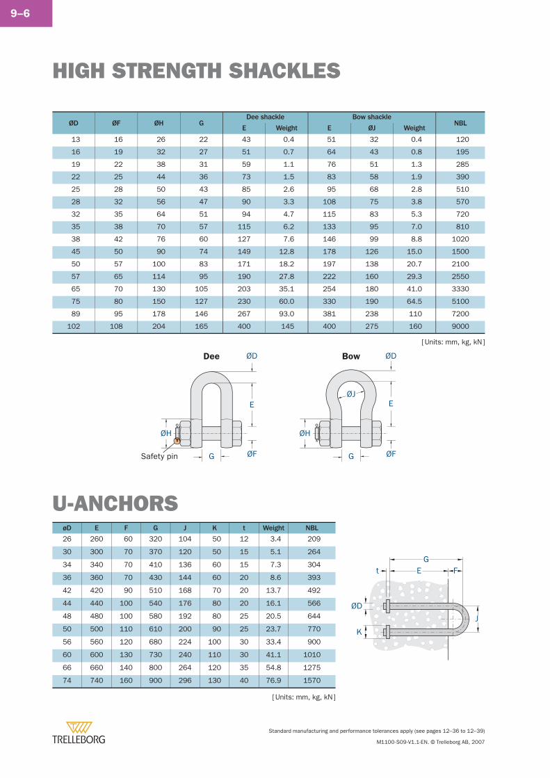
HIGH STRENGTH SHACKLES
Standard manufacturing and performance tolerances apply (see pages 12–36 to 12–39)
M1100-S09-V1.1-EN. © Trelleborg AB, 2007
9–6
ØD
GE
J
K
t F
ØD ØF ØH GDee shackle Bow shackle
NBLE Weight E ØJ Weight
13 16 26 22 43 0.4 51 32 0.4 120
16 19 32 27 51 0.7 64 43 0.8 195
19 22 38 31 59 1.1 76 51 1.3 285
22 25 44 36 73 1.5 83 58 1.9 390
25 28 50 43 85 2.6 95 68 2.8 510
28 32 56 47 90 3.3 108 75 3.8 570
32 35 64 51 94 4.7 115 83 5.3 720
35 38 70 57 115 6.2 133 95 7.0 810
38 42 76 60 127 7.6 146 99 8.8 1020
45 50 90 74 149 12.8 178 126 15.0 1500
50 57 100 83 171 18.2 197 138 20.7 2100
57 65 114 95 190 27.8 222 160 29.3 2550
65 70 130 105 203 35.1 254 180 41.0 3330
75 80 150 127 230 60.0 330 190 64.5 5100
89 95 178 146 267 93.0 381 238 110 7200
102 108 204 165 400 145 400 275 160 9000
ØD
E
ØF
ØH
G
ØJ
ØH
ØD
E
ØFGSafety pin
Dee Bow
U-ANCHORSøD E F G J K t Weight NBL
26 260 60 320 104 50 12 3.4 209
30 300 70 370 120 50 15 5.1 264
34 340 70 410 136 60 15 7.3 304
36 360 70 430 144 60 20 8.6 393
42 420 90 510 168 70 20 13.7 492
44 440 100 540 176 80 20 16.1 566
48 480 100 580 192 80 25 20.5 644
50 500 110 610 200 90 25 23.7 770
56 560 120 680 224 100 30 33.4 900
60 600 130 730 240 110 30 41.1 1010
66 660 140 800 264 120 35 54.8 1275
74 740 160 900 296 130 40 76.9 1570
[ Units: mm, kg, kN ]
[ Units: mm, kg, kN ]
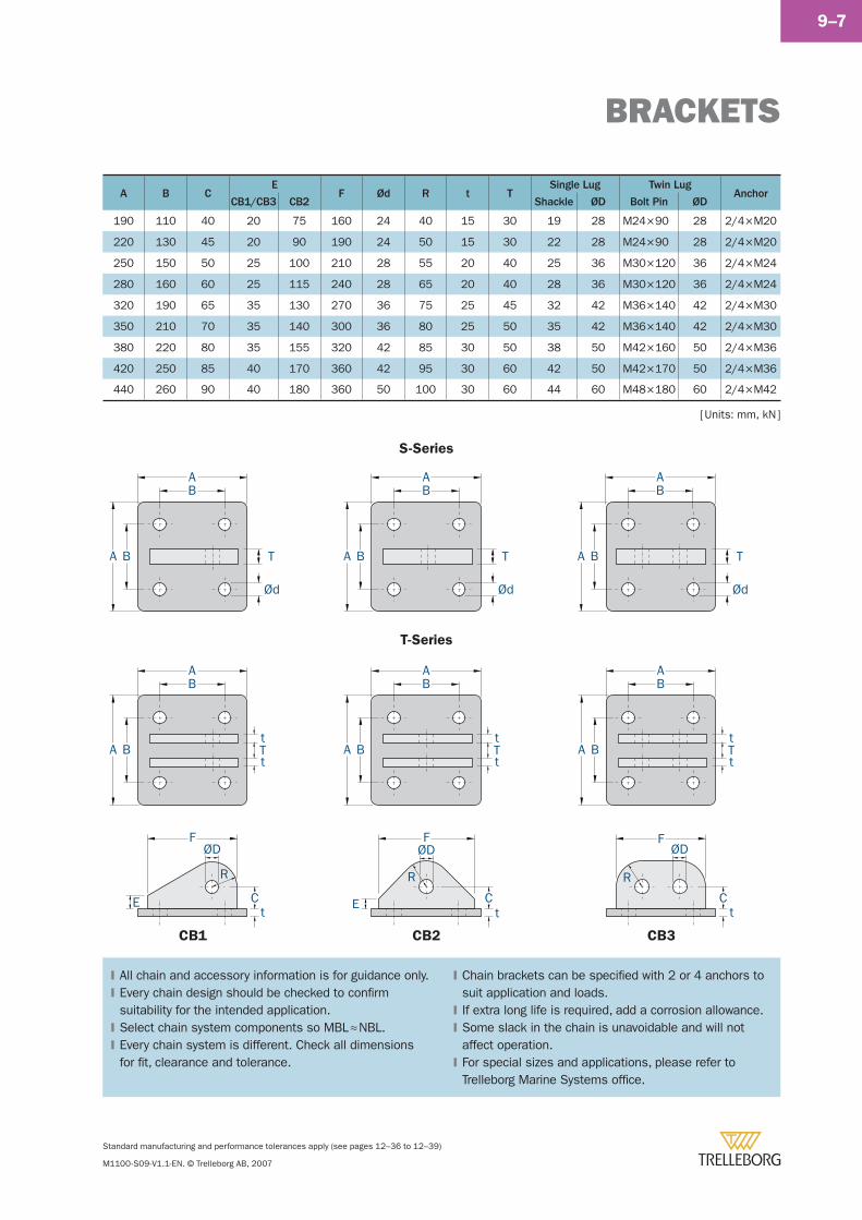
BRACKETS
Standard manufacturing and performance tolerances apply (see pages 12–36 to 12–39)
M1100-S09-V1.1-EN. © Trelleborg AB, 2007
9–7
S-Series
All chain and accessory information is for guidance only.Every chain design should be checked to confi rm suitability for the intended application.Select chain system components so MBL ≈ NBL.Every chain system is different. Check all dimensions for fi t, clearance and tolerance.
�
�
�
�
Chain brackets can be specifi ed with 2 or 4 anchors to suit application and loads.If extra long life is required, add a corrosion allowance.Some slack in the chain is unavoidable and will not affect operation.For special sizes and applications, please refer to Trelleborg Marine Systems offi ce.
�
�
�
�
[ Units: mm, kN ]
Tt
t
AB
A B Tt
t
AB
A B Tt
t
AB
A B
AB
A B
AB
A B
AB
A B T
Ct
E
FØD
Ød
T
Ød
T
Ød
R
FØD
R
Ct
E
R
Ct
FØD
T-Series
CB1 CB2 CB3
A B CE
F Ød R t TSingle Lug Twin Lug
AnchorCB1/CB3 CB2 Shackle ØD Bolt Pin ØD
190 110 40 20 75 160 24 40 15 30 19 28 M24 × 90 28 2/4 × M20
220 130 45 20 90 190 24 50 15 30 22 28 M24 × 90 28 2/4 × M20
250 150 50 25 100 210 28 55 20 40 25 36 M30 × 120 36 2/4 × M24
280 160 60 25 115 240 28 65 20 40 28 36 M30 × 120 36 2/4 × M24
320 190 65 35 130 270 36 75 25 45 32 42 M36 × 140 42 2/4 × M30
350 210 70 35 140 300 36 80 25 50 35 42 M36 × 140 42 2/4 × M30
380 220 80 35 155 320 42 85 30 50 38 50 M42 × 160 50 2/4 × M36
420 250 85 40 170 360 42 95 30 60 42 50 M42 × 170 50 2/4 × M36
440 260 90 40 180 360 50 100 30 60 44 60 M48 × 180 60 2/4 × M42
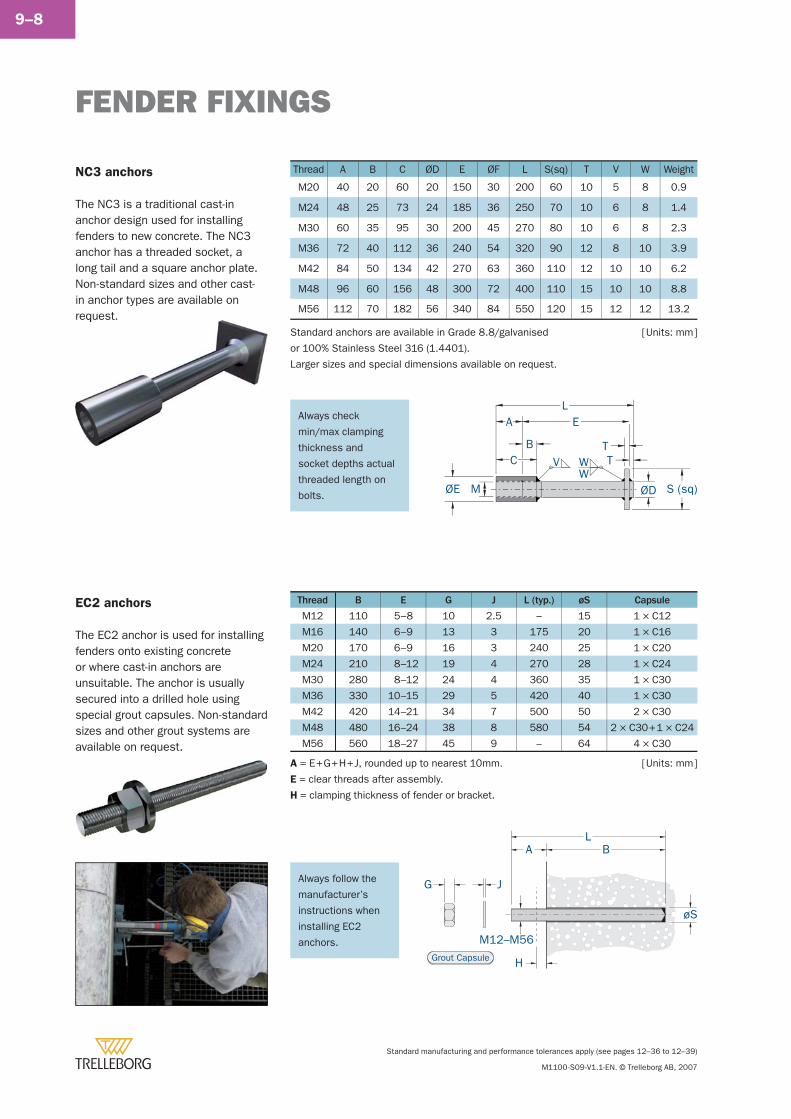
FENDER FIXINGS
Standard manufacturing and performance tolerances apply (see pages 12–36 to 12–39)
M1100-S09-V1.1-EN. © Trelleborg AB, 2007
9–8
NC3 anchors
The NC3 is a traditional cast-in anchor design used for installing fenders to new concrete. The NC3 anchor has a threaded socket, a long tail and a square anchor plate. Non-standard sizes and other cast-in anchor types are available on request.
EL
S (sq)ØE M ØD
B
VC
A
TTW
W
EC2 anchors
The EC2 anchor is used for installing fenders onto existing concrete or where cast-in anchors are unsuitable. The anchor is usually secured into a drilled hole using special grout capsules. Non-standard sizes and other grout systems are available on request.
J
M12–M56Grout Capsule
L
G
øS
H
A B
[ Units: mm ]
[ Units: mm ]
Always follow the
manufacturer’s
instructions when
installing EC2
anchors.
Thread B E G J L (typ.) øS Capsule
M12 110 5–8 10 2.5 – 15 1 × C12
M16 140 6–9 13 3 175 20 1 × C16
M20 170 6–9 16 3 240 25 1 × C20
M24 210 8–12 19 4 270 28 1 × C24
M30 280 8–12 24 4 360 35 1 × C30
M36 330 10–15 29 5 420 40 1 × C30
M42 420 14–21 34 7 500 50 2 × C30
M48 480 16–24 38 8 580 54 2 × C30 + 1 × C24
M56 560 18–27 45 9 – 64 4 × C30
A = E + G + H + J, rounded up to nearest 10mm.
E = clear threads after assembly.
H = clamping thickness of fender or bracket.
Always check
min/max clamping
thickness and
socket depths actual
threaded length on
bolts.
Thread A B C ØD E ØF L S(sq) T V W Weight
M20 40 20 60 20 150 30 200 60 10 5 8 0.9
M24 48 25 73 24 185 36 250 70 10 6 8 1.4
M30 60 35 95 30 200 45 270 80 10 6 8 2.3
M36 72 40 112 36 240 54 320 90 12 8 10 3.9
M42 84 50 134 42 270 63 360 110 12 10 10 6.2
M48 96 60 156 48 300 72 400 110 15 10 10 8.8
M56 112 70 182 56 340 84 550 120 15 12 12 13.2
Standard anchors are available in Grade 8.8/galvanised
or 100% Stainless Steel 316 (1.4401).
Larger sizes and special dimensions available on request.
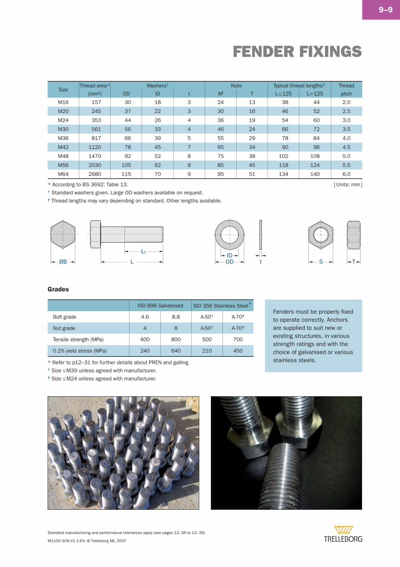
FENDER FIXINGS
Standard manufacturing and performance tolerances apply (see pages 12–36 to 12–39)
M1100-S09-V1.1-EN. © Trelleborg AB, 2007
9–9
ØB L
LT
OD t S TID
SizeThread area*
(mm2)
Washers† Nuts Typical thread lengths‡ Thread
pitchOD ID t AF T L ≤ 125 L > 125
M16 157 30 18 3 24 13 38 44 2.0
M20 245 37 22 3 30 16 46 52 2.5
M24 353 44 26 4 36 19 54 60 3.0
M30 561 56 33 4 46 24 66 72 3.5
M36 817 66 39 5 55 29 78 84 4.0
M42 1120 78 45 7 65 34 90 96 4.5
M48 1470 92 52 8 75 38 102 108 5.0
M56 2030 105 62 9 85 45 118 124 5.5
M64 2680 115 70 9 95 51 134 140 6.0
[ Units: mm ]* According to BS 3692: Table 13.† Standard washers given. Large OD washers available on request.‡ Thread lengths may vary depending on standard. Other lengths available.
Grades
ISO 898 Galvanised ISO 356 Stainless Steel*
Bolt grade 4.6 8.8 A-50† A-70‡
Nut grade 4 8 A-50† A-70‡
Tensile strength (MPa) 400 800 500 700
0.2% yield stress (MPa) 240 640 210 450
Fenders must be properly fi xed to operate correctly. Anchors are supplied to suit new or existing structures, in various strength ratings and with the choice of galvanised or various stainless steels.* Refer to p12–31 for further details about PREN and galling.
† Size ≤ M39 unless agreed with manufacturer.‡ Size ≤ M24 unless agreed with manufacturer.

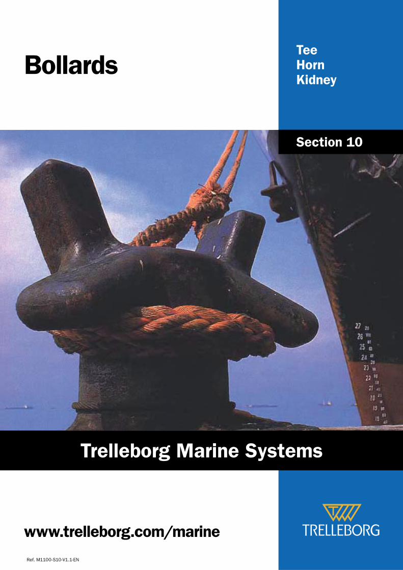
www.trelleborg.com/marine
TeeHornKidney
Bollards
Ref. M1100-S10-V1.1-EN
Section 10
Trelleborg Marine Systems
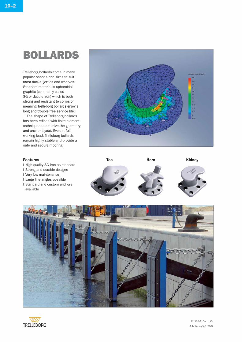
M1100-S10-V1.1-EN
© Trelleborg AB, 2007
10–2
BOLLARDSTrelleborg bollards come in many popular shapes and sizes to suit most docks, jetties and wharves. Standard material is spheroidal graphite (commonly called SG or ductile iron) which is both strong and resistant to corrosion, meaning Trelleborg bollards enjoy a long and trouble free service life.
The shape of Trelleborg bollards has been refi ned with fi nite element techniques to optimize the geometry and anchor layout. Even at full working load, Trelleborg bollards remain highly stable and provide a safe and secure mooring.
Features
High quality SG iron as standardStrong and durable designsVery low maintenanceLarge line angles possibleStandard and custom anchors available
�
�
�
�
�
Tee Horn Kidney
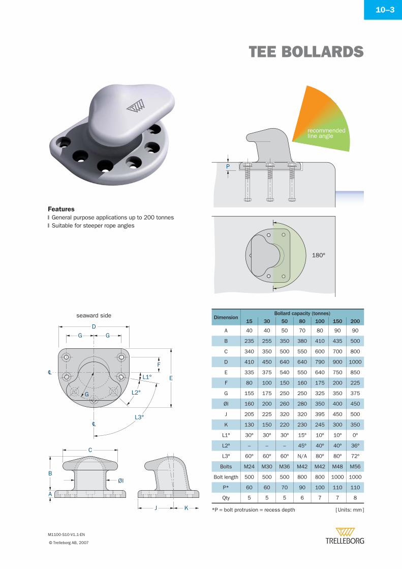
TEE BOLLARDS
M1100-S10-V1.1-EN
© Trelleborg AB, 2007
10–3
[ Units: mm ]
Features
General purpose applications up to 200 tonnesSuitable for steeper rope angles�
�
recommendedline angle
180º
P
cL
cL
D
G
G
G
L3°
L2°
L1°
F
E
J K
C
B
A
ØI
seaward side DimensionBollard capacity (tonnes)
15 30 50 80 100 150 200
A 40 40 50 70 80 90 90
B 235 255 350 380 410 435 500
C 340 350 500 550 600 700 800
D 410 450 640 640 790 900 1000
E 335 375 540 550 640 750 850
F 80 100 150 160 175 200 225
G 155 175 250 250 325 350 375
ØI 160 200 260 280 350 400 450
J 205 225 320 320 395 450 500
K 130 150 220 230 245 300 350
L1º 30º 30º 30º 15º 10º 10º 0º
L2º – – – 45º 40º 40º 36º
L3º 60º 60º 60º N/A 80º 80º 72º
Bolts M24 M30 M36 M42 M42 M48 M56
Bolt length 500 500 500 800 800 1000 1000
P* 60 60 70 90 100 110 110
Qty 5 5 5 6 7 7 8
*P = bolt protrusion = recess depth
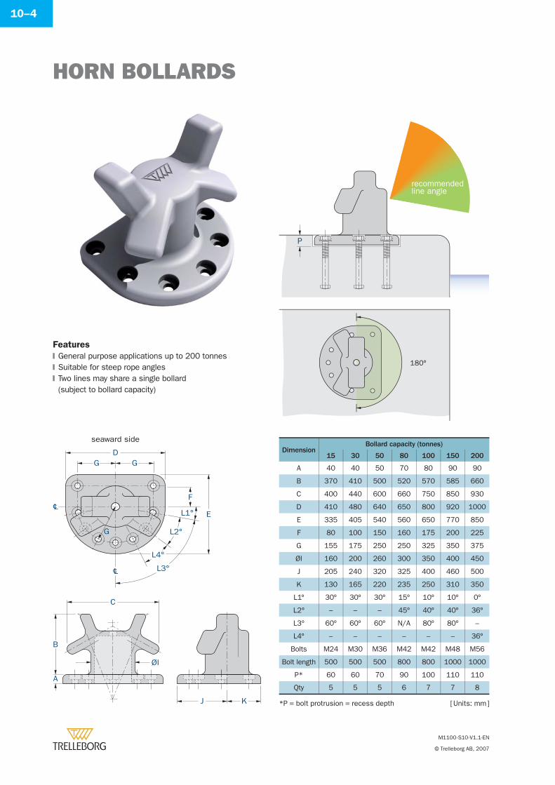
HORN BOLLARDS
M1100-S10-V1.1-EN
© Trelleborg AB, 2007
10–4
L3°
L4°
L2°
L1°
D
E
F
C
ØI
B
A
J K
G G
cL
cL
G
seaward side
recommendedline angle
180º
P
Features
General purpose applications up to 200 tonnesSuitable for steep rope anglesTwo lines may share a single bollard(subject to bollard capacity)
�
�
�
DimensionBollard capacity (tonnes)
15 30 50 80 100 150 200
A 40 40 50 70 80 90 90
B 370 410 500 520 570 585 660
C 400 440 600 660 750 850 930
D 410 480 640 650 800 920 1000
E 335 405 540 560 650 770 850
F 80 100 150 160 175 200 225
G 155 175 250 250 325 350 375
ØI 160 200 260 300 350 400 450
J 205 240 320 325 400 460 500
K 130 165 220 235 250 310 350
L1º 30º 30º 30º 15º 10º 10º 0º
L2º – – – 45º 40º 40º 36º
L3º 60º 60º 60º N/A 80º 80º –
L4º – – – – – – 36º
Bolts M24 M30 M36 M42 M42 M48 M56
Bolt length 500 500 500 800 800 1000 1000
P* 60 60 70 90 100 110 110
Qty 5 5 5 6 7 7 8
[ Units: mm ]*P = bolt protrusion = recess depth
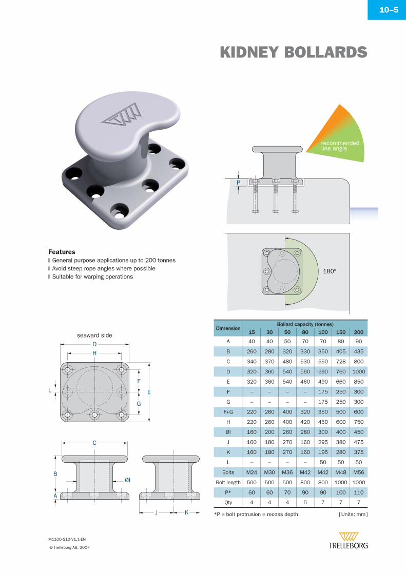
KIDNEY BOLLARDS
M1100-S10-V1.1-EN
© Trelleborg AB, 2007
10–5
D
H
C
E
F
G
L
B
A
J K
ØI
seaward side
Features
General purpose applications up to 200 tonnesAvoid steep rope angles where possibleSuitable for warping operations
�
�
�
180º
recommendedline angle
P
DimensionBollard capacity (tonnes)
15 30 50 80 100 150 200
A 40 40 50 70 70 80 90
B 260 280 320 330 350 405 435
C 340 370 480 530 550 728 800
D 320 360 540 560 590 760 1000
E 320 360 540 460 490 660 850
F – – – – 175 250 300
G – – – – 175 250 300
F+G 220 260 400 320 350 500 600
H 220 260 400 420 450 600 750
ØI 160 200 260 280 300 400 450
J 160 180 270 160 295 380 475
K 160 180 270 160 195 280 375
L – – – – 50 50 50
Bolts M24 M30 M36 M42 M42 M48 M56
Bolt length 500 500 500 800 800 1000 1000
P* 60 60 70 90 90 100 110
Qty 4 4 4 5 7 7 7
[ Units: mm ]*P = bolt protrusion = recess depth
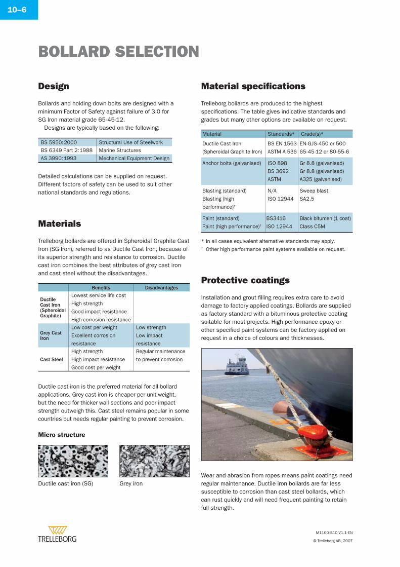
BOLLARD SELECTION
M1100-S10-V1.1-EN
© Trelleborg AB, 2007
10–6
Installation and grout fi lling requires extra care to avoid damage to factory applied coatings. Bollards are supplied as factory standard with a bituminous protective coating suitable for most projects. High performance epoxy or other specifi ed paint systems can be factory applied on request in a choice of colours and thicknesses.
Protective coatings
Bollards and holding down bolts are designed with a minimum Factor of Safety against failure of 3.0 for SG Iron material grade 65-45-12.
Designs are typically based on the following:
BS 5950: 2000 Structural Use of Steelwork
BS 6349 Part 2: 1988 Marine Structures
AS 3990: 1993 Mechanical Equipment Design
Detailed calculations can be supplied on request. Different factors of safety can be used to suit other national standards and regulations.
Grey ironDuctile cast iron (SG)
Design
Micro structure
Trelleborg bollards are offered in Spheroidal Graphite Cast Iron (SG Iron), referred to as Ductile Cast Iron, because of its superior strength and resistance to corrosion. Ductile cast iron combines the best attributes of grey cast iron and cast steel without the disadvantages.
Materials
Ductile cast iron is the preferred material for all bollard applications. Grey cast iron is cheaper per unit weight, but the need for thicker wall sections and poor impact strength outweigh this. Cast steel remains popular in some countries but needs regular painting to prevent corrosion.
Benefi ts Disadvantages
Ductile Cast Iron (Spheroidal Graphite)
Lowest service life cost
High strength
Good impact resistance
High corrosion resistance
Grey Cast Iron
Low cost per weight
Excellent corrosion
resistance
Low strength
Low impact
resistance
Cast Steel
High strength
High impact resistance
Good cost per weight
Regular maintenance
to prevent corrosion
Trelleborg bollards are produced to the highest specifi cations. The table gives indicative standards and grades but many other options are available on request.
Material specifi cations
Material Standards* Grade(s)*
Ductile Cast Iron
(Spheroidal Graphite Iron)
BS EN 1563
ASTM A 536
EN-GJS-450 or 500
65-45-12 or 80-55-6
Anchor bolts (galvanised) ISO 898
BS 3692
ASTM
Gr 8.8 (galvanised)
Gr 8.8 (galvanised)
A325 (galvanised)
Blasting (standard)
Blasting (high
performance)†
N/A
ISO 12944
Sweep blast
SA2.5
Paint (standard)
Paint (high performance)†BS3416
ISO 12944
Black bitumen (1 coat)
Class C5M
* In all cases equivalent alternative standards may apply.† Other high performance paint systems available on request.
Wear and abrasion from ropes means paint coatings need regular maintenance. Ductile iron bollards are far less susceptible to corrosion than cast steel bollards, which can rust quickly and will need frequent painting to retain full strength.
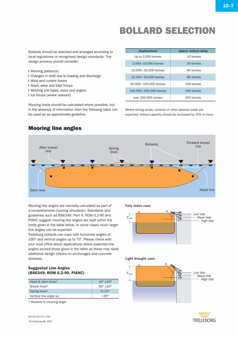
BOLLARD SELECTION
M1100-S10-V1.1-EN
© Trelleborg AB, 2007
10–7
Mooring loads should be calculated where possible, but in the absence of information then the following table can be used as an approximate guideline.
Bollards should be selected and arranged according to local regulations or recognised design standards. The design process should consider:
Mooring pattern(s)Changes in draft due to loading and dischargeWind and current forcesSwell, wave and tidal forcesMooring line types, sizes and anglesIce forces (where relevant)
�
�
�
�
�
�
Displacement Approx. bollard rating
Up to 2,000 tonnes 10 tonnes
2,000 – 10,000 tonnes 30 tonnes
10,000 – 20,000 tonnes 60 tonnes
20,000 – 50,000 tonnes 80 tonnes
50,000 – 100,000 tonnes 100 tonnes
100,000 – 200,000 tonnes 150 tonnes
over 200,000 tonnes 200 tonnes
Where strong winds, currents or other adverse loads are
expected, bollard capacity should be increased by 25% or more.
Stern line
After breastline
Forward breastlineSpring
lines
Bollards
Head line
Mooring line angles
Mooring line angles are normally calculated as part of a comprehensive mooring simulation. Standards and guidelines such as BS6349 : Part 4, ROM 0.2-90 and PIANC suggest mooring line angles are kept within the limits given in the table below. In some cases much larger line angles can be expected.Trelleborg bollards can cope with horizontal angles of ±90° and vertical angles up to 75°. Please check with your local offi ce about applications where expected line angles exceed those given in the table as these may need additional design checks on anchorages and concrete stresses.
Suggested Line Angles
(BS6349, ROM 0.2-90, PIANC)
Head & stern lines* 45° ±15°
Breast lines* 90° ±30°
Spring lines* 5–10°
Vertical line angle (α) <30°
Low tideMean tide
High tide
Low tideMean tide
High tide
α
α
Fmax
Fmin
Fully laden case
Light draught case
* Relative to mooring angle
INSTALLATION
M1100-S10-V1.1-EN
© Trelleborg AB, 2007
10–8
Embedded Through Retrofi t (epoxy grouted bolts)
D+40E+40
P
groutbollard
P
Concrete recess
Fixing options
* refer to dimensions tables
Recessing the bollard is generally recognised as superior to surface mounting. Recessing the base prevents the bollard from working loose on its bolts or cracking the grout bed – especially relevant for high use locations.
Bollards must be installed correctly for a long and trouble-free service life. Anchors should be accurately set out with the supplied template. Bollards can be recessed (as shown) or alternatively surface mounted. Once the grout has reached full strength, anchors can be fully tightened. Mastic is often applied around exposed threads to ease future removal.
Quality assurance
Bollards are safety critical items and quality is paramount. A typical quality documentation package will include:
Dimensioned drawings of bollard and accessoriesBollard and anchorage calculations (if required)Factory inspection reportPhysical properties report for castingInstallation instructions
�
�
�
�
�
ROM 0.2-90 (1990)Actions in the Design of Maritime and Harbor Works
BS6349: Part 4 (1994)Code of Practice for Design of Fendering and Mooring Systems
PIANC Report of WG24 (1995)Criteria for Movements of Moored Ships in Harbours – A Practical Guide (1995)
EAU (1996)Recommendations of the Committee for Waterfront Structures
PIANC Report of PTC II-30 (1997)Approach Channels: A Guide for Design (Appendix B – Typical Ship Dimensions)
Ministry of Transport, Japan (1999)Technical Note No.911 – Ship Dimensions of Design Ships under given Confi dence Limits
ROSA – Defenses D’accostage (2000)Recommandations pour Le Calcul Aux Etats-Limitesdes Ouvrages En Site Aquatique defenses D’accostage
PIANC Report of WG33 (2002)Guidelines for the Design of Fender Systems (2002)
Codes and guidelines
Fuse bolts available on special request.
PROJECT REQUIREMENTS
M1100-S10-V1.1-EN
© Trelleborg AB, 2007
10–9
PROJECT DETAILS
Port
Project
Designer
Contractor
PROJECT STATUS
TMS Ref:
Preliminary
Detail design
Tender
BOLLARD TYPE Quantity ___________ No. Quantity ___________ No.
Tee Horn Kidney
Capacity/SWL _________t Capacity/SWL _________t
Tee Horn Kidney
Tee Horn Kidney
VESSEL INFORMATION LOA __________________m LOA __________________m
Overall length (LOA)Displacement (MD)Deadweight (DWT)
MD __________________m MD __________________m
DWT _________________t DWT _________________t
OTHER INFORMATION FURTHER DETAILS AVAILABLE FROM
Name
Position
Company
Tel
Fax
LINE ANGLE
Min _______________ deg Max _______________ deg
Min _______________ deg Max _______________ deg
MOUNTING
Recessed Surface
Recessed
Surface
Recessed
Surface

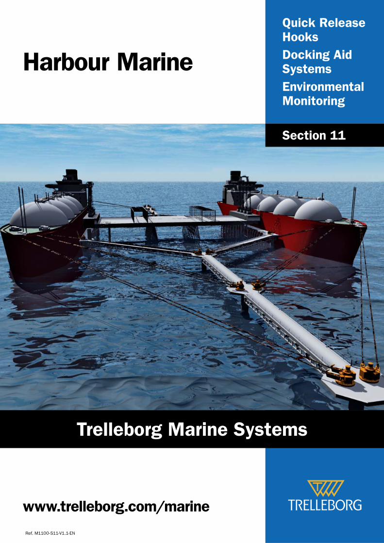
Quick Release Hooks
Docking Aid Systems
Environmental Monitoring
Harbour Marine
Ref. M1100-S11-V1.1-EN
Section 11
www.trelleborg.com/marine
Trelleborg Marine Systems
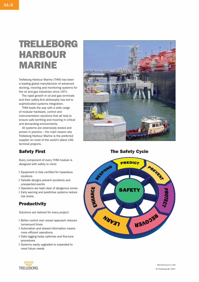
M1100-S11-V1.1-EN
© Trelleborg AB, 2007
11–2
TRELLEBORGHARBOUR MARINETrelleborg Harbour Marine (THM) has been a leading global manufacturer of advanced docking, mooring and monitoring systems for the oil and gas industries since 1971.
The rapid growth in oil and gas terminals and their safety-fi rst philosophy has led to sophisticated systems integration.
THM leads the way with a wide range of modular hardware, control and instrumentation solutions that all help to ensure safe berthing and mooring in critical and demanding environments.
All systems are extensively tested and proven in practice – the main reason why Trelleborg Harbour Marine is the preferred supplier on most of the world’s latest LNG terminal projects.
Safety First
Every component of every THM module is designed with safety in mind:
Equipment is fully certifi ed for hazardous locationsFailsafe designs prevent accidents and unexpected eventsOperators are kept clear of dangerous zonesEarly warning and predictive systems reduce risk levels.
�
�
�
�
Productivity
Solutions are tailored for every project:
Better control over vessel approach reduces turnaround timesAutomation and shared information means more effi cient operationsData logging helps optimise and fi ne-tune proceduresSystems easily upgraded or expanded to meet future needs
�
�
�
�
The Safety Cycle
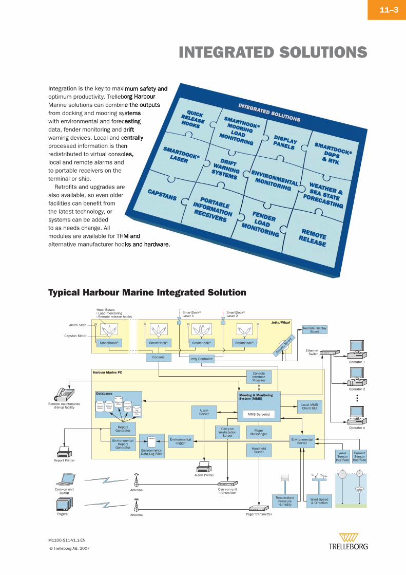
INTEGRATED SOLUTIONS
M1100-S11-V1.1-EN
© Trelleborg AB, 2007
11–3
Integration is the key to maximum safety and optimum productivity. Trelleborg Harbour Marine solutions can combine the outputs from docking and mooring systems with environmental and forecasting data, fender monitoring and drift warning devices. Local and centrally processed information is then redistributed to virtual consoles, local and remote alarms and to portable receivers on the terminal or ship.
Retrofi ts and upgrades are also available, so even older facilities can benefi t from the latest technology, or systems can be added to as needs change. All modules are available for THM and alternative manufacturer hooks and hardware.
Typical Harbour Marine Integrated Solution
Pagers
Carry-on unitlaptop
Carry-on unittransmitter
Report Printer
Alarm Printer
Remote maintenancedial-up facility
Operator 1
Operator 2
Operator n
Antenna
Pager transmitterAntenna
AlarmServer
ConsoleInterfaceProgram
Local MMSClient GUI
WaveSensor
Interface
CurrentSensor
Interface
SmartHook®
EnvironmentalReport
GeneratorEnvironmentalData Log Files
DockingData
MooringData
TemperaturePressureHumidity
Wind Speed& Direction
SmartHook®
Jetty Controller
Remote DisplayBoard
SmartHook®SmartHook®
Hook Bases Load monitoring Remote release hooks
Console
PagerMessenger
HandheldServer
Display
Boa
rd
EnvironmentalServer
ReportGenerator
TagDefinition
File
Vesseltables
HistoryData
Alarm Siren
Capstan Motor
SmartDock®Laser 1
SmartDock®Laser 2
EthernetSwitch
Jetty/Wharf
Harbour Marine PC
DatabasesMooring & MonitoringSystem (MMS)
EnvironmentalLogger
Carry-onWorkstation
Server
MMS Server(s)
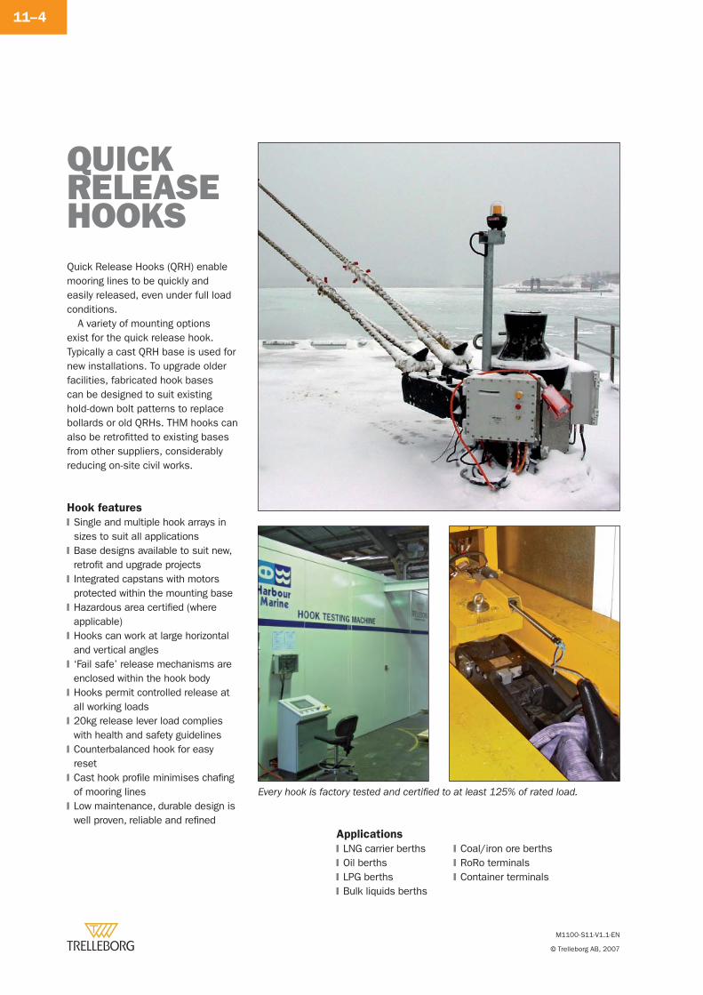
M1100-S11-V1.1-EN
© Trelleborg AB, 2007
11–4
Quick Release Hooks (QRH) enable mooring lines to be quickly and easily released, even under full load conditions.
A variety of mounting options exist for the quick release hook. Typically a cast QRH base is used for new installations. To upgrade older facilities, fabricated hook bases can be designed to suit existing hold-down bolt patterns to replace bollards or old QRHs. THM hooks can also be retrofi tted to existing bases from other suppliers, considerably reducing on-site civil works.
QUICKRELEASEHOOKS
Hook features
Single and multiple hook arrays in sizes to suit all applicationsBase designs available to suit new, retrofi t and upgrade projectsIntegrated capstans with motors protected within the mounting baseHazardous area certifi ed (where applicable)Hooks can work at large horizontal and vertical angles‘Fail safe’ release mechanisms are enclosed within the hook bodyHooks permit controlled release at all working loads20kg release lever load complies with health and safety guidelinesCounterbalanced hook for easy resetCast hook profi le minimises chafi ng of mooring linesLow maintenance, durable design is well proven, reliable and refi ned
�
�
�
�
�
�
�
�
�
�
�
Applications
LNG carrier berthsOil berthsLPG berthsBulk liquids berths
�
�
�
�
Every hook is factory tested and certifi ed to at least 125% of rated load.
Coal/iron ore berthsRoRo terminalsContainer terminals
�
�
�
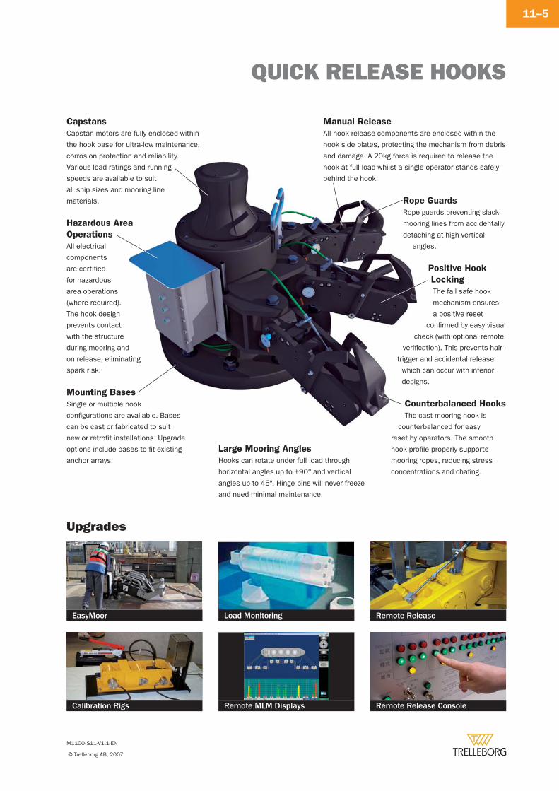
QUICK RELEASE HOOKS
M1100-S11-V1.1-EN
© Trelleborg AB, 2007
11–5
Capstans
Capstan motors are fully enclosed within
the hook base for ultra-low maintenance,
corrosion protection and reliability.
Various load ratings and running
speeds are available to suit
all ship sizes and mooring line
materials.
Calibration Rigs Remote MLM Displays Remote Release Console
EasyMoor Load Monitoring Remote Release
Upgrades
Mounting Bases
Single or multiple hook
confi gurations are available. Bases
can be cast or fabricated to suit
new or retrofi t installations. Upgrade
options include bases to fi t existing
anchor arrays.
Manual Release
All hook release components are enclosed within the
hook side plates, protecting the mechanism from debris
and damage. A 20kg force is required to release the
hook at full load whilst a single operator stands safely
behind the hook.
Rope Guards
Rope guards preventing slack
mooring lines from accidentally
detaching at high vertical
angles.
Large Mooring Angles
Hooks can rotate under full load through
horizontal angles up to ±90° and vertical
angles up to 45°. Hinge pins will never freeze
and need minimal maintenance.
Positive Hook
Locking
The fail safe hook
mechanism ensures
a positive reset
confi rmed by easy visual
check (with optional remote
verifi cation). This prevents hair-
trigger and accidental release
which can occur with inferior
designs.
Counterbalanced Hooks
The cast mooring hook is
counterbalanced for easy
reset by operators. The smooth
hook profi le properly supports
mooring ropes, reducing stress
concentrations and chafi ng.
Hazardous Area
Operations
All electrical
components
are certifi ed
for hazardous
area operations
(where required).
The hook design
prevents contact
with the structure
during mooring and
on release, eliminating
spark risk.
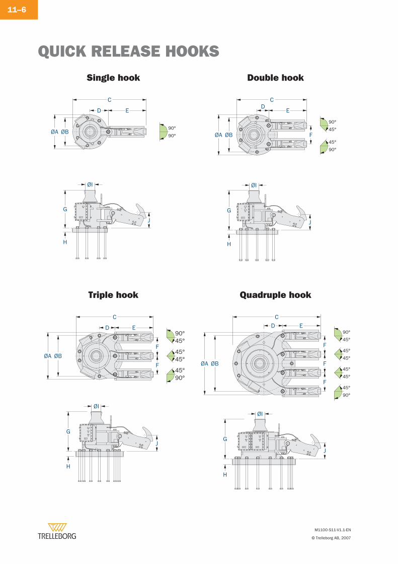
QUICK RELEASE HOOKS
M1100-S11-V1.1-EN
© Trelleborg AB, 2007
11–6
ØA ØB
C
D E
G
ØI
H
J
90°
90° ØA ØB F
CD
E
G
ØI
H
J
90°
45°
90°
45°
C
D E
F
F
ØA ØB
G
H
J
ØI
90°45°
90°45°
45°45°
F
F
F
CD E
ØA ØB
J
G
H
ØI
90°
45°
90°
45°
45°
45°
45°
45°
Single hook Double hook
Triple hook Quadruple hook
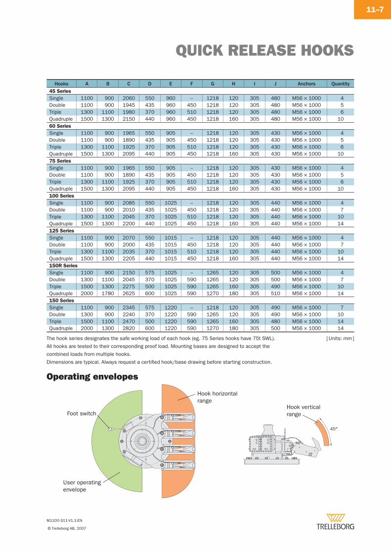
QUICK RELEASE HOOKS
M1100-S11-V1.1-EN
© Trelleborg AB, 2007
11–7
The hook series designates the safe working load of each hook (eg. 75 Series hooks have 75t SWL).
All hooks are tested to their corresponding proof load. Mounting bases are designed to accept the
combined loads from multiple hooks.
Dimensions are typical. Always request a certifi ed hook/base drawing before starting construction.
Hooks A B C D E F G H I J Anchors Quantity45 Series
Single 1100 900 2060 550 960 – 1218 120 305 480 M56 × 1000 4Double 1100 900 1945 435 960 450 1218 120 305 480 M56 × 1000 5Triple 1300 1100 1980 370 960 510 1218 120 305 480 M56 × 1000 6Quadruple 1500 1300 2150 440 960 450 1218 160 305 480 M56 × 1000 1060 Series
Single 1100 900 1965 550 905 – 1218 120 305 430 M56 × 1000 4Double 1100 900 1890 435 905 450 1218 120 305 430 M56 × 1000 5Triple 1300 1100 1925 370 905 510 1218 120 305 430 M56 × 1000 6Quadruple 1500 1300 2095 440 905 450 1218 160 305 430 M56 × 1000 1075 Series
Single 1100 900 1965 550 905 – 1218 120 305 430 M56 × 1000 4Double 1100 900 1890 435 905 450 1218 120 305 430 M56 × 1000 5Triple 1300 1100 1925 370 905 510 1218 120 305 430 M56 × 1000 6Quadruple 1500 1300 2095 440 905 450 1218 160 305 430 M56 × 1000 10100 Series
Single 1100 900 2085 550 1025 – 1218 120 305 440 M56 × 1000 4Double 1100 900 2010 435 1025 450 1218 120 305 440 M56 × 1000 7Triple 1300 1100 2045 370 1025 510 1218 120 305 440 M56 × 1000 10Quadruple 1500 1300 2200 440 1025 450 1218 160 305 440 M56 × 1000 14125 Series
Single 1100 900 2070 550 1015 – 1218 120 305 440 M56 × 1000 4Double 1100 900 2000 435 1015 450 1218 120 305 440 M56 × 1000 7Triple 1300 1100 2035 370 1015 510 1218 120 305 440 M56 × 1000 10Quadruple 1500 1300 2205 440 1015 450 1218 160 305 440 M56 × 1000 14150R Series
Single 1100 900 2150 575 1025 – 1265 120 305 500 M56 × 1000 4Double 1300 1100 2045 370 1025 590 1265 120 305 500 M56 × 1000 7Triple 1500 1300 2275 500 1025 590 1265 160 305 490 M56 × 1000 10Quadruple 2000 1780 2625 600 1025 590 1270 180 305 510 M56 × 1000 14150 Series
Single 1100 900 2345 575 1220 – 1218 120 305 490 M56 × 1000 7Double 1300 900 2240 370 1220 590 1265 120 305 490 M56 × 1000 10Triple 1500 1100 2470 500 1220 590 1265 160 305 480 M56 × 1000 14Quadruple 2000 1300 2820 600 1220 590 1270 180 305 500 M56 × 1000 14
[ Units: mm ]
45°
Hook horizontalrange
Hook vertical range
User operatingenvelope
Foot switch
Operating envelopes
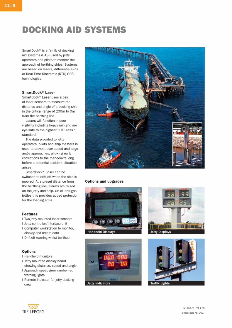
DOCKING AID SYSTEMS
M1100-S11-V1.1-EN
© Trelleborg AB, 2007
11–8
SmartDock® is a family of docking aid systems (DAS) used by jetty operators and pilots to monitor the approach of berthing ships. Systems are based on lasers, differential GPS or Real Time Kinematic (RTK) GPS technologies.
SmartDock® Laser
SmartDock® Laser uses a pair of laser sensors to measure the distance and angle of a docking ship in the critical range of 200m to 0m from the berthing line.
Lasers will function in poor visibility including heavy rain and are eye-safe to the highest FDA Class 1 standard.
The data provided to jetty operators, pilots and ship masters is used to prevent over-speed and large angle approaches, allowing early corrections to the manoeuvre long before a potential accident situation arises.
SmartDock® Laser can be switched to drift-off when the ship is moored. At a preset distance from the berthing line, alarms are raised on the jetty and ship. On oil and gas jetties this provides added protection for the loading arms.
Traffi c LightsJetty Indicators
Handheld Displays
Options and upgrades
Options
Handheld monitorsJetty mounted display board showing distance, speed and angleApproach speed green-amber-red warning lightsRemote indicator for jetty docking crew
�
�
�
�
Features
Two jetty mounted laser sensorsJetty controller/interface unitComputer workstation to monitor, display and record dataDrift-off warning whilst berthed
�
�
�
�
Jetty Displays
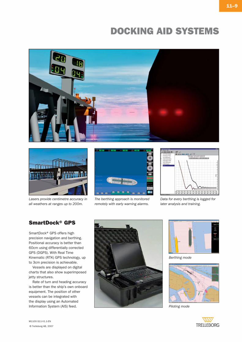
DOCKING AID SYSTEMS
M1100-S11-V1.1-EN
© Trelleborg AB, 2007
11–9
SmartDock® GPS
Lasers provide centimetre accuracy in all weathers at ranges up to 200m.
The berthing approach is monitored remotely with early warning alarms.
Data for every berthing is logged for later analysis and training.
SmartDock® GPS offers high precision navigation and berthing. Positional accuracy is better than 60cm using differentially corrected GPS (DGPS). With Real Time Kinematic (RTK) GPS technology, up to 3cm precision is achievable.
Vessels are displayed on digital charts that also show superimposed jetty structures.
Rate of turn and heading accuracy is better than the ship’s own onboard equipment. The position of other vessels can be integrated with the display using an Automated Information System (AIS) feed.
Berthing mode
Piloting mode
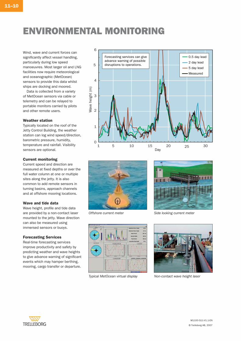
ENVIRONMENTAL MONITORING
M1100-S11-V1.1-EN
© Trelleborg AB, 2007
11–10
Wind, wave and current forces can signifi cantly affect vessel handling, particularly during low speed manoeuvres. Most larger oil and LNG facilities now require meteorological and oceanographic (MetOcean) sensors to provide this data whilst ships are docking and moored.
Data is collected from a variety of MetOcean sensors via cable or telemetry and can be relayed to portable monitors carried by pilots and other remote users.
Weather station
Typically located on the roof of the Jetty Control Building, the weather station can log wind speed/direction, barometric pressure, humidity, temperature and rainfall. Visibility sensors are optional.
Current monitoring
Current speed and direction are measured at fi xed depths or over the full water column at one or multiple sites along the jetty. It is also common to add remote sensors in turning basins, approach channels and at offshore mooring locations.
Wave and tide data
Wave height, profi le and tide data are provided by a non-contact laser mounted to the jetty. Wave direction can also be measured using immersed sensors or buoys.
Forecasting Services
Real-time forecasting services improve productivity and safety by predicting weather and wave heights to give advance warning of signifi cant events which may hamper berthing, mooring, cargo transfer or departure.
Side looking current meter
Typical MetOcean virtual display Non-contact wave height laser
Offshore current meter
5
1 5 10 15 20 25 30
Wav
e he
ight
(m
)
Day
0
1
2
3
4
6
0.5 day lead
2 day lead
5 day lead
Measured
Forecasting services can giveadvance warning of possibledisruptions to operations.
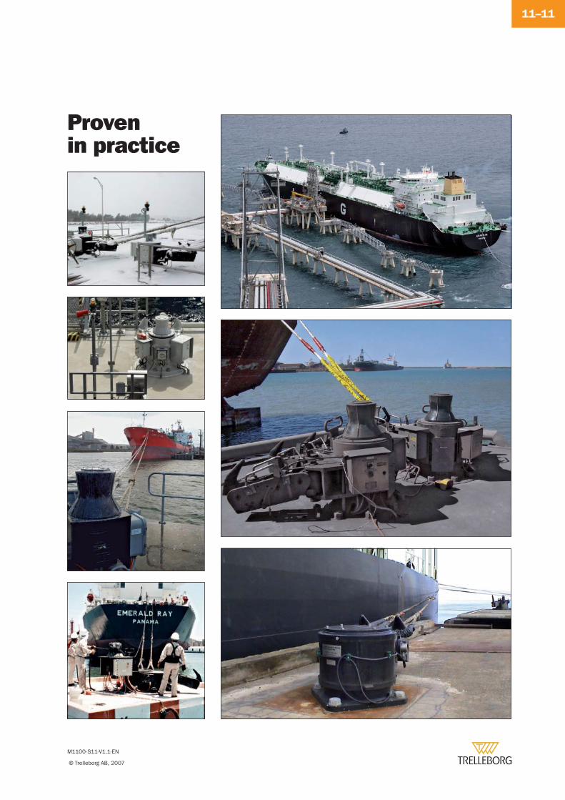
M1100-S11-V1.1-EN
© Trelleborg AB, 2007
11–11
Provenin practice

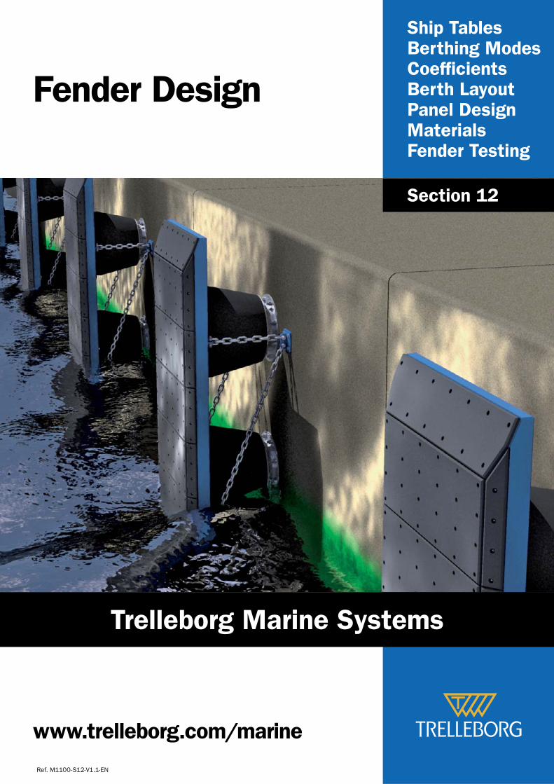
Ship TablesBerthing ModesCoeffi cientsBerth LayoutPanel DesignMaterialsFender Testing
Fender Design
Ref. M1100-S12-V1.1-EN
Section 12
www.trelleborg.com/marine
Trelleborg Marine Systems
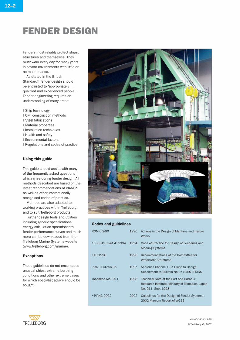
FENDER DESIGN
M1100-S12-V1.1-EN
© Trelleborg AB, 2007
12–2
Fenders must reliably protect ships, structures and themselves. They must work every day for many years in severe environments with little or no maintenance.
As stated in the British Standard†, fender design should be entrusted to ‘appropriately qualifi ed and experienced people’. Fender engineering requires an understanding of many areas:
Ship technologyCivil construction methodsSteel fabricationsMaterial propertiesInstallation techniquesHealth and safetyEnvironmental factorsRegulations and codes of practice
Using this guide
This guide should assist with many of the frequently asked questions which arise during fender design. All methods described are based on the latest recommendations of PIANC*
as well as other internationally recognised codes of practice.
Methods are also adapted to working practices within Trelleborg and to suit Trelleborg products.
Further design tools and utilities including generic specifi cations, energy calculation spreadsheets, fender performance curves and much more can be downloaded from the Trelleborg Marine Systems website (www.trelleborg.com/marine).
Exceptions
These guidelines do not encompass unusual ships, extreme berthing conditions and other extreme cases for which specialist advice should be sought.
�
�
�
�
�
�
�
�
Codes and guidelines
ROM 0.2-90 1990 Actions in the Design of Maritime and Harbor
Works
† BS6349 : Part 4 : 1994 1994 Code of Practice for Design of Fendering and
Mooring Systems
EAU 1996 1996 Recommendations of the Committee for
Waterfront Structures
PIANC Bulletin 95 1997 Approach Channels – A Guide to Design
Supplement to Bulletin No.95 (1997) PIANC
Japanese MoT 911 1998 Technical Note of the Port and Harbour
Research Institute, Ministry of Transport, Japan
No. 911, Sept 1998
* PIANC 2002 2002 Guidelines for the Design of Fender Systems :
2002 Marcom Report of WG33
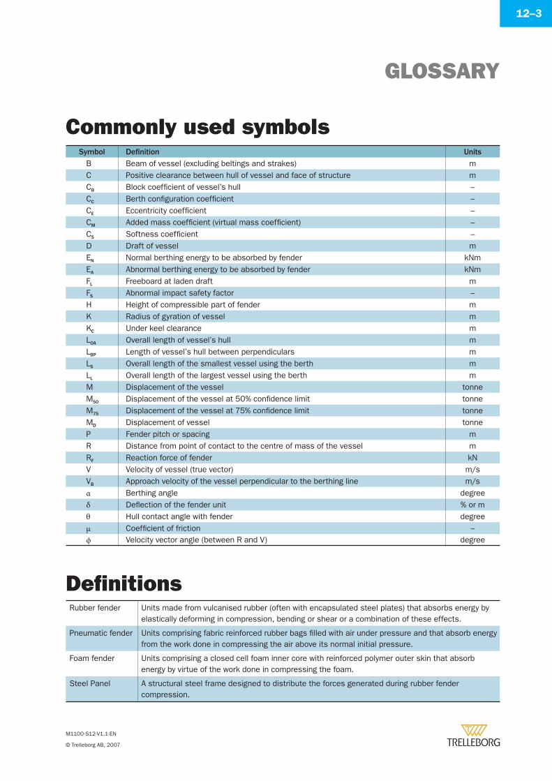
GLOSSARY
M1100-S12-V1.1-EN
© Trelleborg AB, 2007
12–3
Symbol Defi nition UnitsB Beam of vessel (excluding beltings and strakes) mC Positive clearance between hull of vessel and face of structure mCB Block coeffi cient of vessel’s hull –CC Berth confi guration coeffi cient –CE Eccentricity coeffi cient –CM Added mass coeffi cient (virtual mass coeffi cient) –CS Softness coeffi cient –D Draft of vessel mEN Normal berthing energy to be absorbed by fender kNmEA Abnormal berthing energy to be absorbed by fender kNmFL Freeboard at laden draft mFS Abnormal impact safety factor –H Height of compressible part of fender mK Radius of gyration of vessel mKC Under keel clearance mLOA Overall length of vessel’s hull mLBP Length of vessel’s hull between perpendiculars mLS Overall length of the smallest vessel using the berth mLL Overall length of the largest vessel using the berth mM Displacement of the vessel tonneM50 Displacement of the vessel at 50% confi dence limit tonneM75 Displacement of the vessel at 75% confi dence limit tonneMD Displacement of vessel tonneP Fender pitch or spacing mR Distance from point of contact to the centre of mass of the vessel mRF Reaction force of fender kNV Velocity of vessel (true vector) m/sVB Approach velocity of the vessel perpendicular to the berthing line m/sα Berthing angle degreeδ Defl ection of the fender unit % or mθ Hull contact angle with fender degreeμ Coeffi cient of friction –ϕ Velocity vector angle (between R and V) degree
Rubber fender Units made from vulcanised rubber (often with encapsulated steel plates) that absorbs energy by elastically deforming in compression, bending or shear or a combination of these effects.
Pneumatic fender Units comprising fabric reinforced rubber bags fi lled with air under pressure and that absorb energy from the work done in compressing the air above its normal initial pressure.
Foam fender Units comprising a closed cell foam inner core with reinforced polymer outer skin that absorb energy by virtue of the work done in compressing the foam.
Steel Panel A structural steel frame designed to distribute the forces generated during rubber fender compression.
Commonly used symbols
Defi nitions
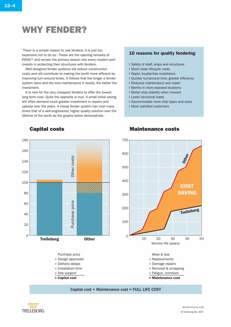
WHY FENDER?
M1100-S12-V1.1-EN
© Trelleborg AB, 2007
12–4
10 reasons for quality fendering
Safety of staff, ships and structures Much lower lifecycle costsRapid, trouble-free installationQuicker turnaround time, greater effi ciencyReduced maintenance and repairBerths in more exposed locationsBetter ship stability when mooredLower structural loadsAccommodate more ship types and sizesMore satisfi ed customers
�
�
�
�
�
�
�
�
�
�
‘There is a simple reason to use fenders: it is just too expensive not to do so’. These are the opening remarks of PIANC* and remain the primary reason why every modern port invests in protecting their structures with fenders.
Well-designed fender systems will reduce construction costs and will contribute to making the berth more effi cient by improving turn-around times. It follows that the longer a fender system lasts and the less maintenance it needs, the better the investment.
It is rare for the very cheapest fenders to offer the lowest long term cost. Quite the opposite is true. A small initial saving will often demand much greater investment in repairs and upkeep over the years. A cheap fender system can cost many times that of a well-engineered, higher quality solution over the lifetime of the berth as the graphs below demonstrate.
Capital costs Maintenance costs
0
20
40
60
80
100
120
140
160
180
Trelleborg Other
Purc
hase
pric
eO
ther
cos
ts
10 20 30 40Service life (years)
500
100
200
300
400
500
600
700
COST
SAVING
Trelleborg
Oth
er
Purchase price+ Design approvals+ Delivery delays+ Installation time+ Site support= Capital cost
Wear & tear+ Replacements+ Damage repairs+ Removal & scrapping+ Fatigue, corrosion= Maintenance cost
Capital cost + Maintenance cost = FULL LIFE COST
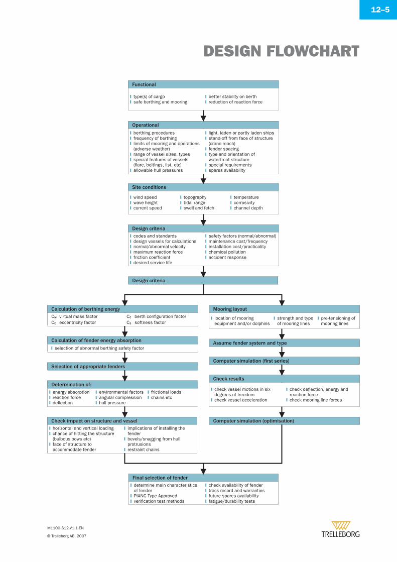
DESIGN FLOWCHART
M1100-S12-V1.1-EN
© Trelleborg AB, 2007
12–5
Functional
type(s) of cargosafe berthing and mooring�
�
better stability on berthreduction of reaction force�
�
Design criteria
Calculation of berthing energyCM virtual mass factorCE eccentricity factor
CC berth confi guration factorCS softness factor
Mooring layout
location of mooring equipment and/or dolphins� strength and type
of mooring lines� pre-tensioning of
mooring lines�
Assume fender system and type
Computer simulation (fi rst series)
Check results
check vessel motions in six degrees of freedomcheck vessel acceleration
�
�
check defl ection, energy and reaction forcecheck mooring line forces
�
�
Computer simulation (optimisation)
Calculation of fender energy absorptionselection of abnormal berthing safety factor�
Selection of appropriate fenders
Determination of:energy absorptionreaction forcedefl ection
�
�
�
environmental factorsangular compressionhull pressure
�
�
�
frictional loadschains etc�
�
Check impact on structure and vesselhorizontal and vertical loadingchance of hitting the structure (bulbous bows etc)face of structure to accommodate fender
�
�
�
implications of installing the fenderbevels/snagging from hull protrusionsrestraint chains
�
�
�
Final selection of fenderdetermine main characteristics of fenderPIANC Type Approvedverifi cation test methods
�
�
�
check availability of fendertrack record and warrantiesfuture spares availabilityfatigue/durability tests
�
�
�
�
Operational
berthing proceduresfrequency of berthinglimits of mooring and operations (adverse weather)range of vessel sizes, typesspecial features of vessels (fl are, beltings, list, etc)allowable hull pressures
�
�
�
�
�
�
light, laden or partly laden shipsstand-off from face of structure (crane reach)fender spacingtype and orientation of waterfront structurespecial requirementsspares availability
�
�
�
�
�
�
Site conditions
wind speedwave heightcurrent speed
�
�
�
topographytidal rangeswell and fetch
�
�
�
temperaturecorrosivitychannel depth
�
�
�
Design criteriacodes and standardsdesign vessels for calculationsnormal/abnormal velocitymaximum reaction forcefriction coeffi cientdesired service life
�
�
�
�
�
�
safety factors (normal/abnormal)maintenance cost/frequencyinstallation cost/practicalitychemical pollutionaccident response
�
�
�
�
�
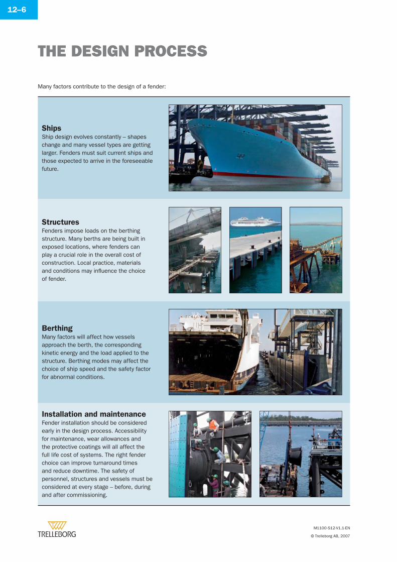
THE DESIGN PROCESS
M1100-S12-V1.1-EN
© Trelleborg AB, 2007
12–6
Many factors contribute to the design of a fender:
ShipsShip design evolves constantly – shapes change and many vessel types are getting larger. Fenders must suit current ships and those expected to arrive in the foreseeable future.
StructuresFenders impose loads on the berthing structure. Many berths are being built in exposed locations, where fenders can play a crucial role in the overall cost of construction. Local practice, materials and conditions may infl uence the choice of fender.
BerthingMany factors will affect how vessels approach the berth, the corresponding kinetic energy and the load applied to the structure. Berthing modes may affect the choice of ship speed and the safety factor for abnormal conditions.
Installation and maintenanceFender installation should be considered early in the design process. Accessibility for maintenance, wear allowances and the protective coatings will all affect the full life cost of systems. The right fender choice can improve turnaround times and reduce downtime. The safety of personnel, structures and vessels must be considered at every stage – before, during and after commissioning.
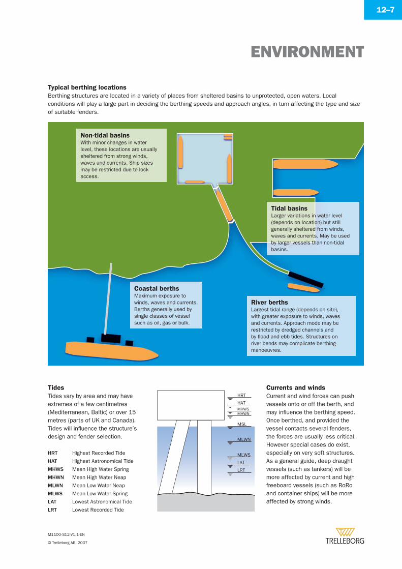
ENVIRONMENT
M1100-S12-V1.1-EN
© Trelleborg AB, 2007
12–7
Berthing structures are located in a variety of places from sheltered basins to unprotected, open waters. Local conditions will play a large part in deciding the berthing speeds and approach angles, in turn affecting the type and size of suitable fenders.
Typical berthing locations
Non-tidal basinsWith minor changes in water level, these locations are usually sheltered from strong winds, waves and currents. Ship sizes may be restricted due to lock access.
Coastal berthsMaximum exposure to winds, waves and currents. Berths generally used by single classes of vessel such as oil, gas or bulk.
River berthsLargest tidal range (depends on site), with greater exposure to winds, waves and currents. Approach mode may be restricted by dredged channels and by fl ood and ebb tides. Structures on river bends may complicate berthing manoeuvres.
Tidal basinsLarger variations in water level (depends on location) but still generally sheltered from winds, waves and currents. May be used by larger vessels than non-tidal basins.
Tides
Tides vary by area and may have extremes of a few centimetres (Mediterranean, Baltic) or over 15 metres (parts of UK and Canada). Tides will infl uence the structure’s design and fender selection.
HRT Highest Recorded Tide
HAT Highest Astronomical Tide
MHWS Mean High Water Spring
MHWN Mean High Water Neap
MLWN Mean Low Water Neap
MLWS Mean Low Water Spring
LAT Lowest Astronomical Tide
LRT Lowest Recorded Tide
Currents and winds
Current and wind forces can push vessels onto or off the berth, and may infl uence the berthing speed.Once berthed, and provided the vessel contacts several fenders, the forces are usually less critical. However special cases do exist, especially on very soft structures. As a general guide, deep draught vessels (such as tankers) will be more affected by current and high freeboard vessels (such as RoRo and container ships) will be more affected by strong winds.
HRT
HATMHWSMHWN
MSL
MLWN
MLWS
LAT
LRT
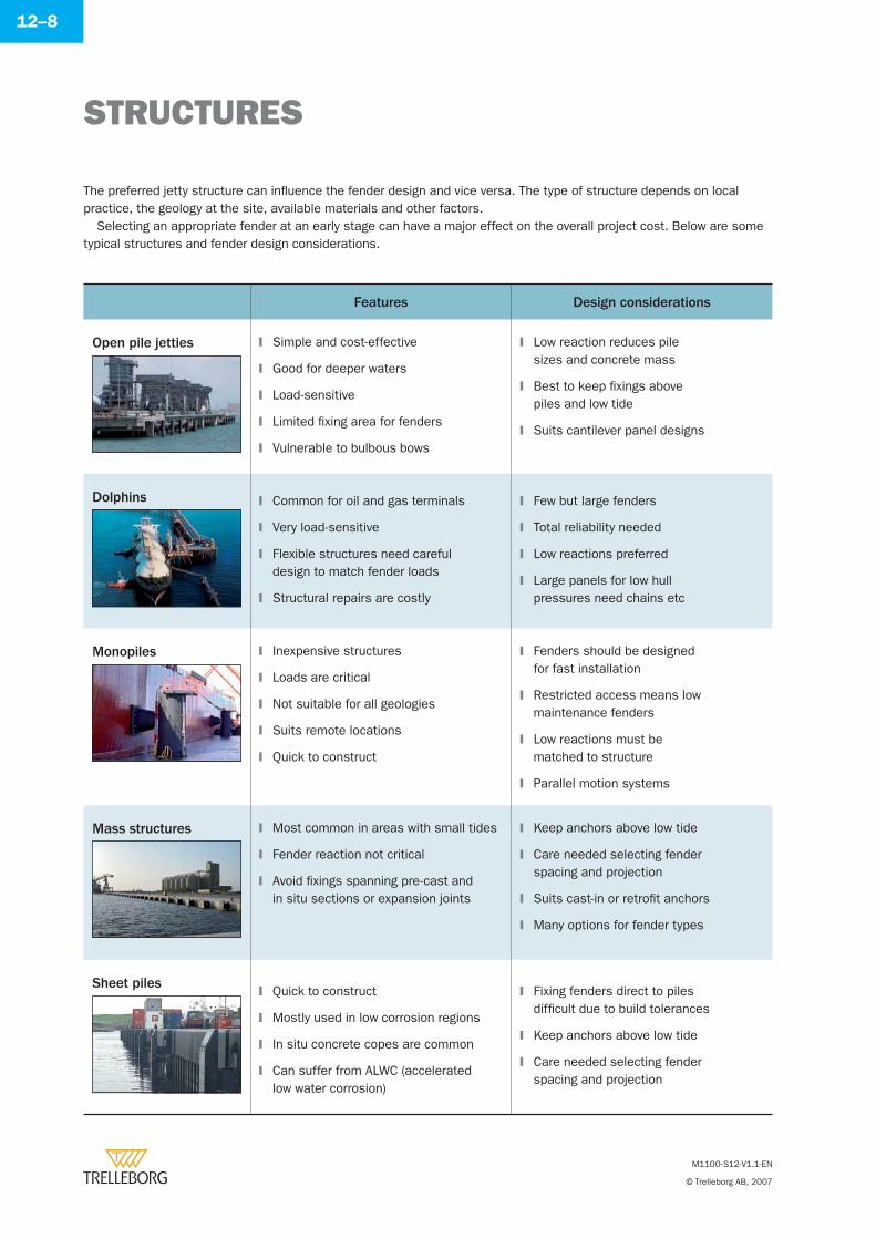
STRUCTURES
M1100-S12-V1.1-EN
© Trelleborg AB, 2007
12–8
Features Design considerations
Open pile jetties Simple and cost-effective
Good for deeper waters
Load-sensitive
Limited fi xing area for fenders
Vulnerable to bulbous bows
�
�
�
�
�
Low reaction reduces pile sizes and concrete mass
Best to keep fi xings above piles and low tide
Suits cantilever panel designs
�
�
�
Dolphins Common for oil and gas terminals
Very load-sensitive
Flexible structures need careful design to match fender loads
Structural repairs are costly
�
�
�
�
Few but large fenders
Total reliability needed
Low reactions preferred
Large panels for low hull pressures need chains etc
�
�
�
�
Monopiles Inexpensive structures
Loads are critical
Not suitable for all geologies
Suits remote locations
Quick to construct
�
�
�
�
�
Fenders should be designed for fast installation
Restricted access means low maintenance fenders
Low reactions must be matched to structure
Parallel motion systems
�
�
�
�
Mass structures Most common in areas with small tides
Fender reaction not critical
Avoid fi xings spanning pre-cast and in situ sections or expansion joints
�
�
�
Keep anchors above low tide
Care needed selecting fender spacing and projection
Suits cast-in or retrofi t anchors
Many options for fender types
�
�
�
�
Sheet pilesQuick to construct
Mostly used in low corrosion regions
In situ concrete copes are common
Can suffer from ALWC (accelerated low water corrosion)
�
�
�
�
Fixing fenders direct to piles diffi cult due to build tolerances
Keep anchors above low tide
Care needed selecting fender spacing and projection
�
�
�
The preferred jetty structure can infl uence the fender design and vice versa. The type of structure depends on local practice, the geology at the site, available materials and other factors.
Selecting an appropriate fender at an early stage can have a major effect on the overall project cost. Below are some typical structures and fender design considerations.
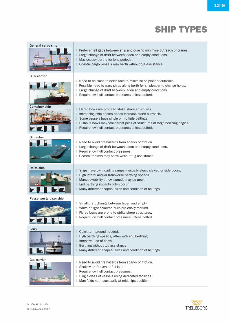
SHIP TYPES
M1100-S12-V1.1-EN
© Trelleborg AB, 2007
12–9
General cargo shipPrefer small gaps between ship and quay to minimise outreach of cranes.Large change of draft between laden and empty conditions.May occupy berths for long periods.Coastal cargo vessels may berth without tug assistance.
�
�
�
�
Bulk carrierNeed to be close to berth face to minimise shiploader outreach.Possible need to warp ships along berth for shiploader to change holds.Large change of draft between laden and empty conditions.Require low hull contact pressures unless belted.
�
�
�
�
Container shipFlared bows are prone to strike shore structures.Increasing ship beams needs increase crane outreach.Some vessels have single or multiple beltings.Bulbous bows may strike front piles of structures at large berthing angles.Require low hull contact pressures unless belted.
�
�
�
�
�
Oil tankerNeed to avoid fi re hazards from sparks or friction.Large change of draft between laden and empty conditions.Require low hull contact pressures.Coastal tankers may berth without tug assistance.
�
�
�
�
RoRo shipShips have own loading ramps – usually stern, slewed or side doors.High lateral and/or transverse berthing speeds.Manoeuvrability at low speeds may be poor.End berthing impacts often occur.Many different shapes, sizes and condition of beltings.
�
�
�
�
�
Passenger (cruise) shipSmall draft change between laden and empty.White or light coloured hulls are easily marked.Flared bows are prone to strike shore structures.Require low hull contact pressures unless belted.
�
�
�
�
FerryQuick turn around needed.High berthing speeds, often with end berthing.Intensive use of berth.Berthing without tug assistance.Many different shapes, sizes and condition of beltings.
�
�
�
�
�
Gas carrierNeed to avoid fi re hazards from sparks or friction.Shallow draft even at full load.Require low hull contact pressures.Single class of vessels using dedicated facilities.Manifolds not necessarily at midships position.
�
�
�
�
�
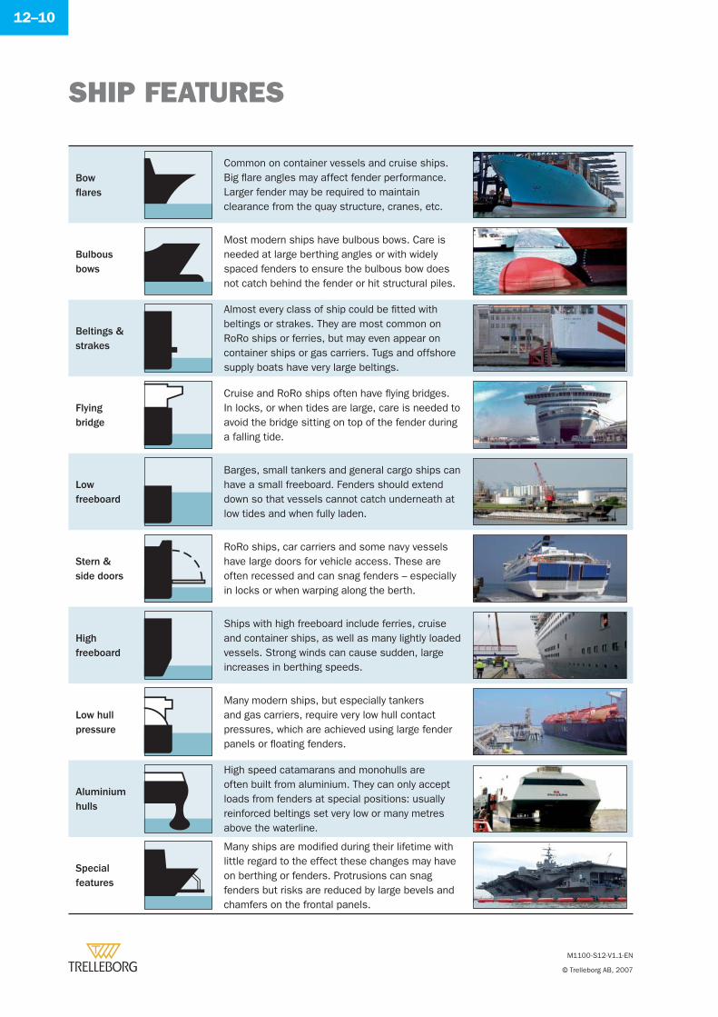
SHIP FEATURES
M1100-S12-V1.1-EN
© Trelleborg AB, 2007
12–10
Bowfl ares
Common on container vessels and cruise ships. Big fl are angles may affect fender performance. Larger fender may be required to maintain clearance from the quay structure, cranes, etc.
Bulbousbows
Most modern ships have bulbous bows. Care is needed at large berthing angles or with widely spaced fenders to ensure the bulbous bow does not catch behind the fender or hit structural piles.
Beltings & strakes
Almost every class of ship could be fi tted with beltings or strakes. They are most common on RoRo ships or ferries, but may even appear on container ships or gas carriers. Tugs and offshore supply boats have very large beltings.
Flyingbridge
Cruise and RoRo ships often have fl ying bridges. In locks, or when tides are large, care is needed to avoid the bridge sitting on top of the fender during a falling tide.
Lowfreeboard
Barges, small tankers and general cargo ships can have a small freeboard. Fenders should extend down so that vessels cannot catch underneath at low tides and when fully laden.
Stern &side doors
RoRo ships, car carriers and some navy vessels have large doors for vehicle access. These are often recessed and can snag fenders – especially in locks or when warping along the berth.
Highfreeboard
Ships with high freeboard include ferries, cruise and container ships, as well as many lightly loaded vessels. Strong winds can cause sudden, large increases in berthing speeds.
Low hull pressure
Many modern ships, but especially tankers and gas carriers, require very low hull contact pressures, which are achieved using large fender panels or fl oating fenders.
Aluminiumhulls
High speed catamarans and monohulls are often built from aluminium. They can only accept loads from fenders at special positions: usually reinforced beltings set very low or many metres above the waterline.
Specialfeatures
Many ships are modifi ed during their lifetime with little regard to the effect these changes may have on berthing or fenders. Protrusions can snag fenders but risks are reduced by large bevels and chamfers on the frontal panels.
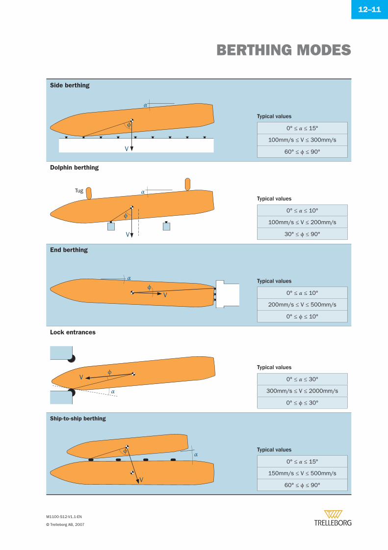
BERTHING MODES
M1100-S12-V1.1-EN
© Trelleborg AB, 2007
12–11
Side berthing
V
ϕ
αTypical values
0° ≤ α ≤ 15°
100mm/s ≤ V ≤ 300mm/s
60° ≤ ϕ ≤ 90°
Dolphin berthing
ϕ
αTug
V
Typical values
0° ≤ α ≤ 10°
100mm/s ≤ V ≤ 200mm/s
30° ≤ ϕ ≤ 90°
End berthing
α
Vϕ
Typical values
0° ≤ α ≤ 10°
200mm/s ≤ V ≤ 500mm/s
0° ≤ ϕ ≤ 10°
Lock entrances
Vϕ
α
Typical values
0° ≤ α ≤ 30°
300mm/s ≤ V ≤ 2000mm/s
0° ≤ ϕ ≤ 30°
Ship-to-ship berthing
ϕ
V
αTypical values
0° ≤ α ≤ 15°
150mm/s ≤ V ≤ 500mm/s
60° ≤ ϕ ≤ 90°
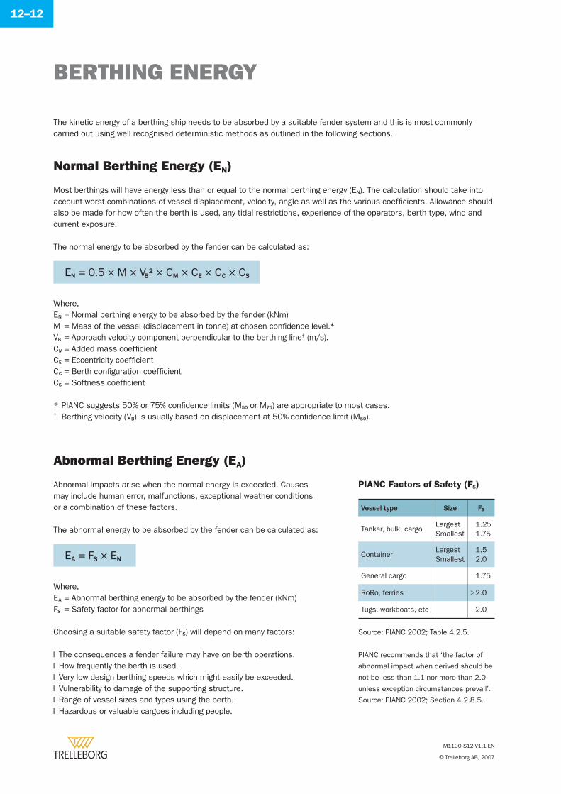
BERTHING ENERGY
M1100-S12-V1.1-EN
© Trelleborg AB, 2007
12–12
The kinetic energy of a berthing ship needs to be absorbed by a suitable fender system and this is most commonly carried out using well recognised deterministic methods as outlined in the following sections.
Normal Berthing Energy (EN)
Most berthings will have energy less than or equal to the normal berthing energy (EN). The calculation should take into account worst combinations of vessel displacement, velocity, angle as well as the various coeffi cients. Allowance should also be made for how often the berth is used, any tidal restrictions, experience of the operators, berth type, wind and current exposure.
The normal energy to be absorbed by the fender can be calculated as:
Where,EN = Normal berthing energy to be absorbed by the fender (kNm)M = Mass of the vessel (displacement in tonne) at chosen confi dence level.*VB = Approach velocity component perpendicular to the berthing line† (m/s).CM = Added mass coeffi cientCE = Eccentricity coeffi cientCC = Berth confi guration coeffi cientCS = Softness coeffi cient
* PIANC suggests 50% or 75% confi dence limits (M50 or M75) are appropriate to most cases.† Berthing velocity (VB) is usually based on displacement at 50% confi dence limit (M50).
Abnormal Berthing Energy (EA)
Abnormal impacts arise when the normal energy is exceeded. Causes may include human error, malfunctions, exceptional weather conditions or a combination of these factors.
The abnormal energy to be absorbed by the fender can be calculated as:
Where,EA = Abnormal berthing energy to be absorbed by the fender (kNm)FS = Safety factor for abnormal berthings
Choosing a suitable safety factor (FS) will depend on many factors:
The consequences a fender failure may have on berth operations.How frequently the berth is used.Very low design berthing speeds which might easily be exceeded.Vulnerability to damage of the supporting structure.Range of vessel sizes and types using the berth.Hazardous or valuable cargoes including people.
�
�
�
�
�
�
PIANC Factors of Safety (FS)
Vessel type Size FS
Tanker, bulk, cargoLargestSmallest
1.251.75
ContainerLargestSmallest
1.52.0
General cargo 1.75
RoRo, ferries ≥ 2.0
Tugs, workboats, etc 2.0
EN = 0.5 × M × VB2 × CM × CE × CC × CS
EA = FS × EN
Source: PIANC 2002; Table 4.2.5.
PIANC recommends that ‘the factor of
abnormal impact when derived should be
not be less than 1.1 nor more than 2.0
unless exception circumstances prevail’.
Source: PIANC 2002; Section 4.2.8.5.
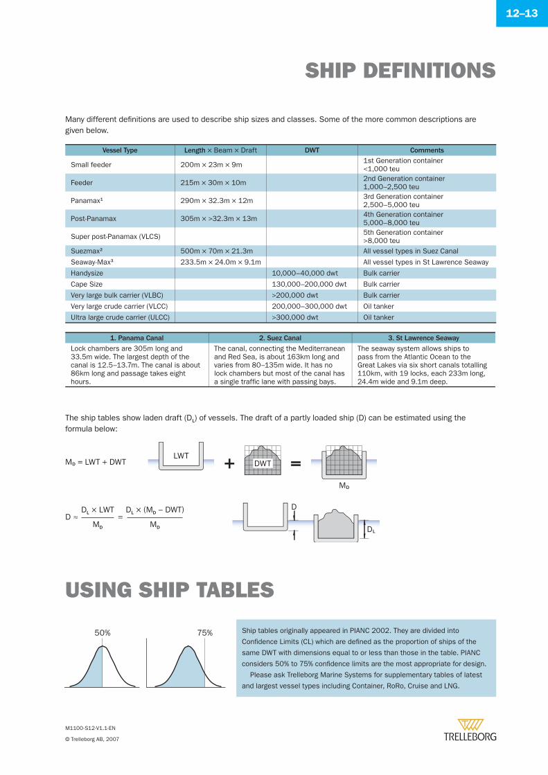
SHIP DEFINITIONS
M1100-S12-V1.1-EN
© Trelleborg AB, 2007
12–13
Many different defi nitions are used to describe ship sizes and classes. Some of the more common descriptions are given below.
USING SHIP TABLES
Ship tables originally appeared in PIANC 2002. They are divided into
Confi dence Limits (CL) which are defi ned as the proportion of ships of the
same DWT with dimensions equal to or less than those in the table. PIANC
considers 50% to 75% confi dence limits are the most appropriate for design.
Please ask Trelleborg Marine Systems for supplementary tables of latest
and largest vessel types including Container, RoRo, Cruise and LNG.
LWT
MD
DWT+ =
D
DL
MD = LWT + DWT
The ship tables show laden draft (DL) of vessels. The draft of a partly loaded ship (D) can be estimated using the formula below:
50% 75%
MD
DL × LWT
MD
DL × (MD – DWT)D ≈ =
Vessel Type Length × Beam × Draft DWT Comments
Small feeder 200m × 23m × 9m 1st Generation container<1,000 teu
Feeder 215m × 30m × 10m 2nd Generation container1,000–2,500 teu
Panamax1 290m × 32.3m × 12m 3rd Generation container2,500–5,000 teu
Post-Panamax 305m × >32.3m × 13m 4th Generation container5,000–8,000 teu
Super post-Panamax (VLCS) 5th Generation container>8,000 teu
Suezmax2 500m × 70m × 21.3m All vessel types in Suez Canal
Seaway-Max3 233.5m × 24.0m × 9.1m All vessel types in St Lawrence Seaway
Handysize 10,000–40,000 dwt Bulk carrier
Cape Size 130,000–200,000 dwt Bulk carrier
Very large bulk carrier (VLBC) >200,000 dwt Bulk carrier
Very large crude carrier (VLCC) 200,000–300,000 dwt Oil tanker
Ultra large crude carrier (ULCC) >300,000 dwt Oil tanker
1. Panama Canal 2. Suez Canal 3. St Lawrence Seaway
Lock chambers are 305m long and 33.5m wide. The largest depth of the canal is 12.5–13.7m. The canal is about 86km long and passage takes eight hours.
The canal, connecting the Mediterranean and Red Sea, is about 163km long and varies from 80–135m wide. It has no lock chambers but most of the canal has a single traffi c lane with passing bays.
The seaway system allows ships to pass from the Atlantic Ocean to the Great Lakes via six short canals totalling 110km, with 19 locks, each 233m long, 24.4m wide and 9.1m deep.
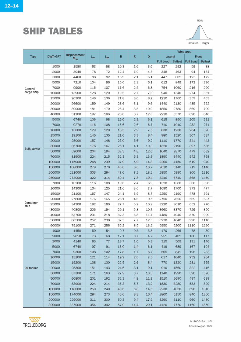
SHIP TABLES
M1100-S12-V1.1-EN
© Trelleborg AB, 2007
12–14
Type DWT/GRT DisplacementM50
LOA LBP B FL DL
Wind area
Lateral Front
Full Load Ballast Full Load Ballast
Generalcargo ship
1000 1580 63 58 10.3 1.6 3.6 227 292 59 88
2000 3040 78 72 12.4 1.9 4.5 348 463 94 134
3000 4460 88 82 13.9 2.1 5.1 447 605 123 172
5000 7210 104 96 16.0 2.3 6.1 612 849 173 236
7000 9900 115 107 17.6 2.5 6.8 754 1060 216 290
10000 13900 128 120 19.5 2.7 7.6 940 1340 274 361
15000 20300 146 136 21.8 3.0 8.7 1210 1760 359 463
20000 26600 159 149 23.6 3.1 9.6 1440 2130 435 552
30000 39000 181 170 26.4 3.5 10.9 1850 2780 569 709
40000 51100 197 186 28.6 3.7 12.0 2210 3370 690 846
Bulk carrier
5000 6740 106 98 15.0 2.3 6.1 615 850 205 231
7000 9270 116 108 16.6 2.6 6.7 710 1010 232 271
10000 13000 129 120 18.5 2.9 7.5 830 1230 264 320
15000 19100 145 135 21.0 3.3 8.4 980 1520 307 387
20000 25000 157 148 23.0 3.6 9.2 1110 1770 341 443
30000 36700 176 167 26.1 4.1 10.3 1320 2190 397 536
50000 59600 204 194 32.3 4.8 12.0 1640 2870 479 682
70000 81900 224 215 32.3 5.3 13.3 1890 3440 542 798
100000 115000 248 239 37.9 5.9 14.8 2200 4150 619 940
150000 168000 279 270 43.0 6.6 16.7 2610 5140 719 1140
200000 221000 303 294 47.0 7.2 18.2 2950 5990 800 1310
250000 273000 322 314 50.4 7.8 19.4 3240 6740 868 1450
Containership
7000 10200 116 108 19.6 2.4 6.9 1320 1360 300 396
10000 14300 134 125 21.6 3.0 7.7 1690 1700 373 477
15000 21100 157 147 24.1 3.9 8.7 2250 2190 478 591
20000 27800 176 165 26.1 4.6 9.5 2750 2620 569 687
25000 34300 192 180 27.7 5.2 10.2 3220 3010 652 770
30000 40800 206 194 29.1 5.8 10.7 3660 3370 729 850
40000 53700 231 218 32.3 6.8 11.7 4480 4040 870 990
50000 66500 252 238 32.3 7.7 12.5 5230 4640 990 1110
60000 79100 271 256 35.2 8.5 13.2 5950 5200 1110 1220
Oil tanker
1000 1450 59 54 9.7 0.5 3.8 170 266 78 80
2000 2810 73 68 12.1 0.7 4.7 251 401 108 117
3000 4140 83 77 13.7 1.0 5.3 315 509 131 146
5000 6740 97 91 16.0 1.4 6.1 419 689 167 194
7000 9300 108 102 17.8 1.7 6.7 505 841 196 233
10000 13100 121 114 19.9 2.0 7.5 617 1040 232 284
15000 19200 138 130 22.5 2.6 8.4 770 1320 281 355
20000 25300 151 143 24.6 3.1 9.1 910 1560 322 416
30000 37300 171 163 27.9 3.7 10.3 1140 1990 390 520
50000 60800 201 192 32.3 4.9 11.9 1510 2690 497 689
70000 83900 224 214 36.3 5.7 13.2 1830 3280 583 829
100000 118000 250 240 40.6 6.8 14.6 2230 4050 690 1010
150000 174000 284 273 46.0 8.3 16.4 2800 5150 840 1260
200000 229000 311 300 50.3 9.4 17.9 3290 6110 960 1480
300000 337000 354 342 57.0 11.4 20.1 4120 7770 1160 1850
smaller
50%
larger
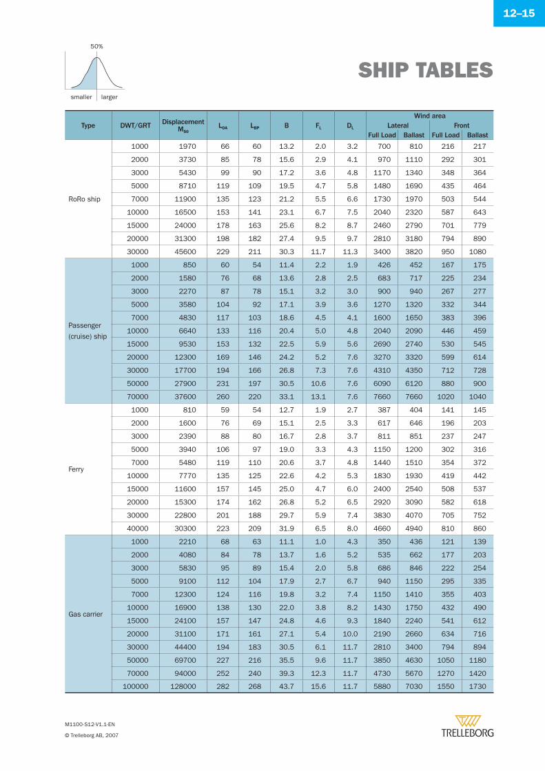
SHIP TABLES
M1100-S12-V1.1-EN
© Trelleborg AB, 2007
12–15
Type DWT/GRT DisplacementM50
LOA LBP B FL DL
Wind areaLateral Front
Full Load Ballast Full Load Ballast
RoRo ship
1000 1970 66 60 13.2 2.0 3.2 700 810 216 217
2000 3730 85 78 15.6 2.9 4.1 970 1110 292 301
3000 5430 99 90 17.2 3.6 4.8 1170 1340 348 364
5000 8710 119 109 19.5 4.7 5.8 1480 1690 435 464
7000 11900 135 123 21.2 5.5 6.6 1730 1970 503 544
10000 16500 153 141 23.1 6.7 7.5 2040 2320 587 643
15000 24000 178 163 25.6 8.2 8.7 2460 2790 701 779
20000 31300 198 182 27.4 9.5 9.7 2810 3180 794 890
30000 45600 229 211 30.3 11.7 11.3 3400 3820 950 1080
Passenger
(cruise) ship
1000 850 60 54 11.4 2.2 1.9 426 452 167 175
2000 1580 76 68 13.6 2.8 2.5 683 717 225 234
3000 2270 87 78 15.1 3.2 3.0 900 940 267 277
5000 3580 104 92 17.1 3.9 3.6 1270 1320 332 344
7000 4830 117 103 18.6 4.5 4.1 1600 1650 383 396
10000 6640 133 116 20.4 5.0 4.8 2040 2090 446 459
15000 9530 153 132 22.5 5.9 5.6 2690 2740 530 545
20000 12300 169 146 24.2 5.2 7.6 3270 3320 599 614
30000 17700 194 166 26.8 7.3 7.6 4310 4350 712 728
50000 27900 231 197 30.5 10.6 7.6 6090 6120 880 900
70000 37600 260 220 33.1 13.1 7.6 7660 7660 1020 1040
Ferry
1000 810 59 54 12.7 1.9 2.7 387 404 141 145
2000 1600 76 69 15.1 2.5 3.3 617 646 196 203
3000 2390 88 80 16.7 2.8 3.7 811 851 237 247
5000 3940 106 97 19.0 3.3 4.3 1150 1200 302 316
7000 5480 119 110 20.6 3.7 4.8 1440 1510 354 372
10000 7770 135 125 22.6 4.2 5.3 1830 1930 419 442
15000 11600 157 145 25.0 4.7 6.0 2400 2540 508 537
20000 15300 174 162 26.8 5.2 6.5 2920 3090 582 618
30000 22800 201 188 29.7 5.9 7.4 3830 4070 705 752
40000 30300 223 209 31.9 6.5 8.0 4660 4940 810 860
Gas carrier
1000 2210 68 63 11.1 1.0 4.3 350 436 121 139
2000 4080 84 78 13.7 1.6 5.2 535 662 177 203
3000 5830 95 89 15.4 2.0 5.8 686 846 222 254
5000 9100 112 104 17.9 2.7 6.7 940 1150 295 335
7000 12300 124 116 19.8 3.2 7.4 1150 1410 355 403
10000 16900 138 130 22.0 3.8 8.2 1430 1750 432 490
15000 24100 157 147 24.8 4.6 9.3 1840 2240 541 612
20000 31100 171 161 27.1 5.4 10.0 2190 2660 634 716
30000 44400 194 183 30.5 6.1 11.7 2810 3400 794 894
50000 69700 227 216 35.5 9.6 11.7 3850 4630 1050 1180
70000 94000 252 240 39.3 12.3 11.7 4730 5670 1270 1420
100000 128000 282 268 43.7 15.6 11.7 5880 7030 1550 1730
smaller
50%
larger
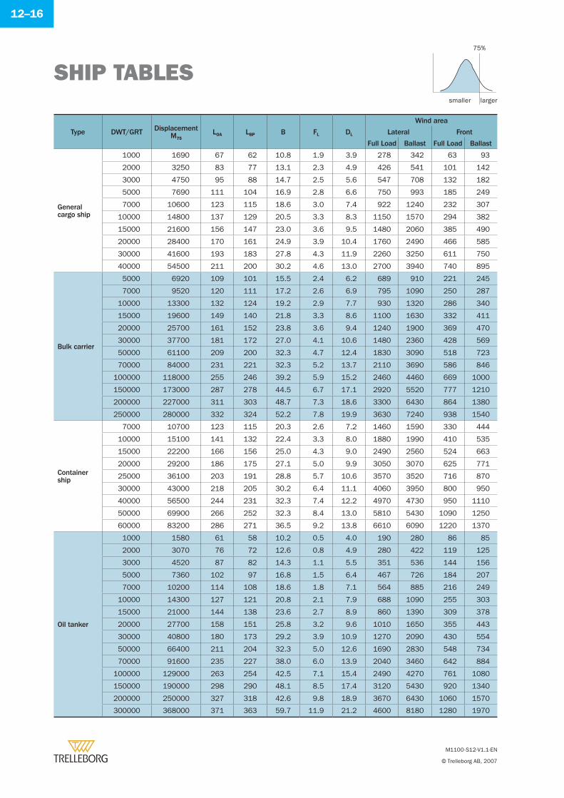
SHIP TABLES
M1100-S12-V1.1-EN
© Trelleborg AB, 2007
12–16
Type DWT/GRT DisplacementM75
LOA LBP B FL DL
Wind area
Lateral Front
Full Load Ballast Full Load Ballast
Generalcargo ship
1000 1690 67 62 10.8 1.9 3.9 278 342 63 93
2000 3250 83 77 13.1 2.3 4.9 426 541 101 142
3000 4750 95 88 14.7 2.5 5.6 547 708 132 182
5000 7690 111 104 16.9 2.8 6.6 750 993 185 249
7000 10600 123 115 18.6 3.0 7.4 922 1240 232 307
10000 14800 137 129 20.5 3.3 8.3 1150 1570 294 382
15000 21600 156 147 23.0 3.6 9.5 1480 2060 385 490
20000 28400 170 161 24.9 3.9 10.4 1760 2490 466 585
30000 41600 193 183 27.8 4.3 11.9 2260 3250 611 750
40000 54500 211 200 30.2 4.6 13.0 2700 3940 740 895
Bulk carrier
5000 6920 109 101 15.5 2.4 6.2 689 910 221 245
7000 9520 120 111 17.2 2.6 6.9 795 1090 250 287
10000 13300 132 124 19.2 2.9 7.7 930 1320 286 340
15000 19600 149 140 21.8 3.3 8.6 1100 1630 332 411
20000 25700 161 152 23.8 3.6 9.4 1240 1900 369 470
30000 37700 181 172 27.0 4.1 10.6 1480 2360 428 569
50000 61100 209 200 32.3 4.7 12.4 1830 3090 518 723
70000 84000 231 221 32.3 5.2 13.7 2110 3690 586 846
100000 118000 255 246 39.2 5.9 15.2 2460 4460 669 1000
150000 173000 287 278 44.5 6.7 17.1 2920 5520 777 1210
200000 227000 311 303 48.7 7.3 18.6 3300 6430 864 1380
250000 280000 332 324 52.2 7.8 19.9 3630 7240 938 1540
Containership
7000 10700 123 115 20.3 2.6 7.2 1460 1590 330 444
10000 15100 141 132 22.4 3.3 8.0 1880 1990 410 535
15000 22200 166 156 25.0 4.3 9.0 2490 2560 524 663
20000 29200 186 175 27.1 5.0 9.9 3050 3070 625 771
25000 36100 203 191 28.8 5.7 10.6 3570 3520 716 870
30000 43000 218 205 30.2 6.4 11.1 4060 3950 800 950
40000 56500 244 231 32.3 7.4 12.2 4970 4730 950 1110
50000 69900 266 252 32.3 8.4 13.0 5810 5430 1090 1250
60000 83200 286 271 36.5 9.2 13.8 6610 6090 1220 1370
Oil tanker
1000 1580 61 58 10.2 0.5 4.0 190 280 86 85
2000 3070 76 72 12.6 0.8 4.9 280 422 119 125
3000 4520 87 82 14.3 1.1 5.5 351 536 144 156
5000 7360 102 97 16.8 1.5 6.4 467 726 184 207
7000 10200 114 108 18.6 1.8 7.1 564 885 216 249
10000 14300 127 121 20.8 2.1 7.9 688 1090 255 303
15000 21000 144 138 23.6 2.7 8.9 860 1390 309 378
20000 27700 158 151 25.8 3.2 9.6 1010 1650 355 443
30000 40800 180 173 29.2 3.9 10.9 1270 2090 430 554
50000 66400 211 204 32.3 5.0 12.6 1690 2830 548 734
70000 91600 235 227 38.0 6.0 13.9 2040 3460 642 884
100000 129000 263 254 42.5 7.1 15.4 2490 4270 761 1080
150000 190000 298 290 48.1 8.5 17.4 3120 5430 920 1340
200000 250000 327 318 42.6 9.8 18.9 3670 6430 1060 1570
300000 368000 371 363 59.7 11.9 21.2 4600 8180 1280 1970
smaller
75%
larger
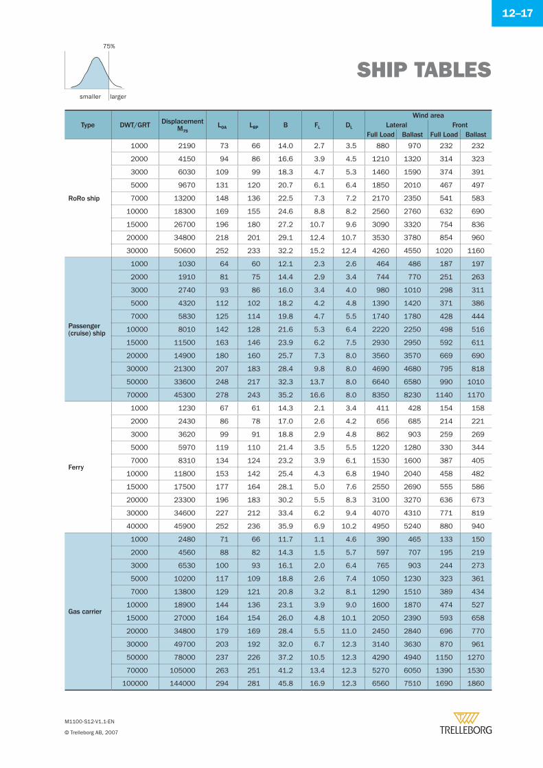
SHIP TABLES
M1100-S12-V1.1-EN
© Trelleborg AB, 2007
12–17
Type DWT/GRT DisplacementM75
LOA LBP B FL DL
Wind areaLateral Front
Full Load Ballast Full Load Ballast
RoRo ship
1000 2190 73 66 14.0 2.7 3.5 880 970 232 232
2000 4150 94 86 16.6 3.9 4.5 1210 1320 314 323
3000 6030 109 99 18.3 4.7 5.3 1460 1590 374 391
5000 9670 131 120 20.7 6.1 6.4 1850 2010 467 497
7000 13200 148 136 22.5 7.3 7.2 2170 2350 541 583
10000 18300 169 155 24.6 8.8 8.2 2560 2760 632 690
15000 26700 196 180 27.2 10.7 9.6 3090 3320 754 836
20000 34800 218 201 29.1 12.4 10.7 3530 3780 854 960
30000 50600 252 233 32.2 15.2 12.4 4260 4550 1020 1160
Passenger(cruise) ship
1000 1030 64 60 12.1 2.3 2.6 464 486 187 197
2000 1910 81 75 14.4 2.9 3.4 744 770 251 263
3000 2740 93 86 16.0 3.4 4.0 980 1010 298 311
5000 4320 112 102 18.2 4.2 4.8 1390 1420 371 386
7000 5830 125 114 19.8 4.7 5.5 1740 1780 428 444
10000 8010 142 128 21.6 5.3 6.4 2220 2250 498 516
15000 11500 163 146 23.9 6.2 7.5 2930 2950 592 611
20000 14900 180 160 25.7 7.3 8.0 3560 3570 669 690
30000 21300 207 183 28.4 9.8 8.0 4690 4680 795 818
50000 33600 248 217 32.3 13.7 8.0 6640 6580 990 1010
70000 45300 278 243 35.2 16.6 8.0 8350 8230 1140 1170
Ferry
1000 1230 67 61 14.3 2.1 3.4 411 428 154 158
2000 2430 86 78 17.0 2.6 4.2 656 685 214 221
3000 3620 99 91 18.8 2.9 4.8 862 903 259 269
5000 5970 119 110 21.4 3.5 5.5 1220 1280 330 344
7000 8310 134 124 23.2 3.9 6.1 1530 1600 387 405
10000 11800 153 142 25.4 4.3 6.8 1940 2040 458 482
15000 17500 177 164 28.1 5.0 7.6 2550 2690 555 586
20000 23300 196 183 30.2 5.5 8.3 3100 3270 636 673
30000 34600 227 212 33.4 6.2 9.4 4070 4310 771 819
40000 45900 252 236 35.9 6.9 10.2 4950 5240 880 940
Gas carrier
1000 2480 71 66 11.7 1.1 4.6 390 465 133 150
2000 4560 88 82 14.3 1.5 5.7 597 707 195 219
3000 6530 100 93 16.1 2.0 6.4 765 903 244 273
5000 10200 117 109 18.8 2.6 7.4 1050 1230 323 361
7000 13800 129 121 20.8 3.2 8.1 1290 1510 389 434
10000 18900 144 136 23.1 3.9 9.0 1600 1870 474 527
15000 27000 164 154 26.0 4.8 10.1 2050 2390 593 658
20000 34800 179 169 28.4 5.5 11.0 2450 2840 696 770
30000 49700 203 192 32.0 6.7 12.3 3140 3630 870 961
50000 78000 237 226 37.2 10.5 12.3 4290 4940 1150 1270
70000 105000 263 251 41.2 13.4 12.3 5270 6050 1390 1530
100000 144000 294 281 45.8 16.9 12.3 6560 7510 1690 1860
smaller
75%
larger
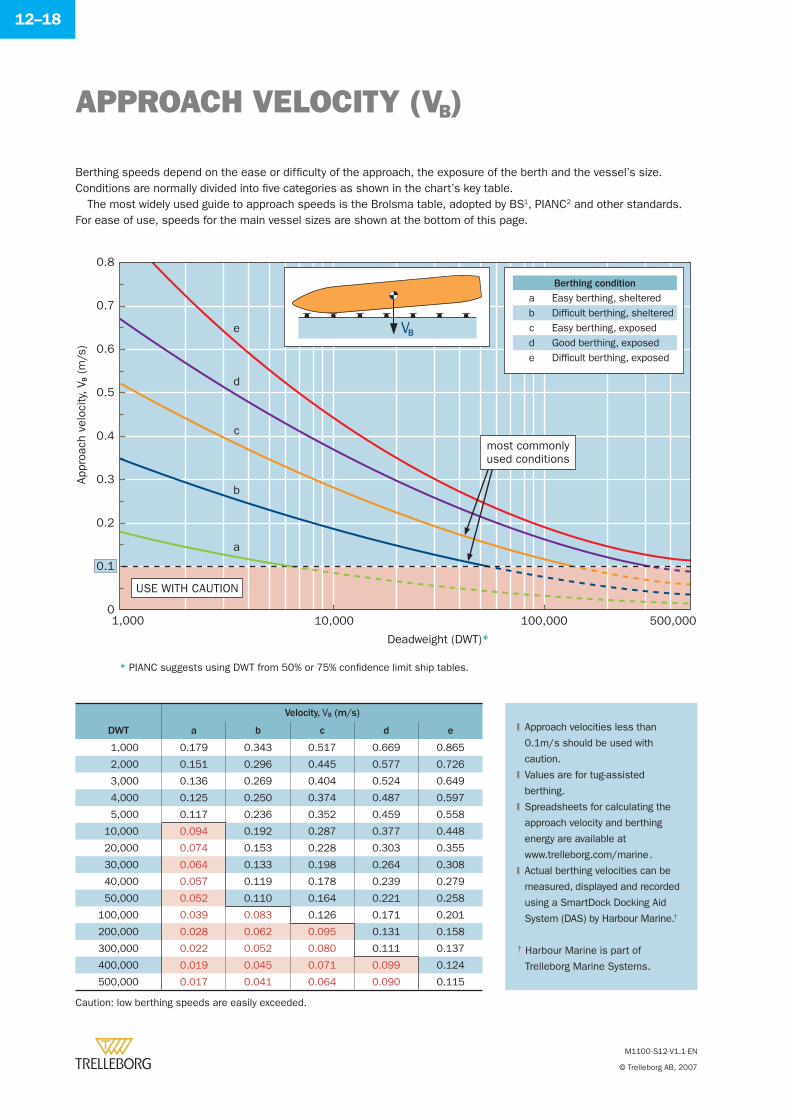
12–18
USE WITH CAUTION
Deadweight (DWT)*
1,000
e
0
0.1
0.2
0.3
0.4
0.5
0.6
0.7
0.8
Appr
oach
vel
ocity
, VB (
m/s
)
500,000100,00010,000
d
c
b
a
most commonlyused conditions
Berthing speeds depend on the ease or diffi culty of the approach, the exposure of the berth and the vessel’s size. Conditions are normally divided into fi ve categories as shown in the chart’s key table.
The most widely used guide to approach speeds is the Brolsma table, adopted by BS1, PIANC2 and other standards. For ease of use, speeds for the main vessel sizes are shown at the bottom of this page.
Berthing conditiona Easy berthing, shelteredb Diffi cult berthing, shelteredc Easy berthing, exposedd Good berthing, exposede Diffi cult berthing, exposed
Velocity, VB (m/s)
DWT a b c d e
1,000 0.179 0.343 0.517 0.669 0.865
2,000 0.151 0.296 0.445 0.577 0.726
3,000 0.136 0.269 0.404 0.524 0.649
4,000 0.125 0.250 0.374 0.487 0.597
5,000 0.117 0.236 0.352 0.459 0.558
10,000 0.094 0.192 0.287 0.377 0.448
20,000 0.074 0.153 0.228 0.303 0.355
30,000 0.064 0.133 0.198 0.264 0.308
40,000 0.057 0.119 0.178 0.239 0.279
50,000 0.052 0.110 0.164 0.221 0.258
100,000 0.039 0.083 0.126 0.171 0.201
200,000 0.028 0.062 0.095 0.131 0.158
300,000 0.022 0.052 0.080 0.111 0.137
400,000 0.019 0.045 0.071 0.099 0.124
500,000 0.017 0.041 0.064 0.090 0.115
Caution: low berthing speeds are easily exceeded.
Approach velocities less than
0.1m/s should be used with
caution.
Values are for tug-assisted
berthing.
Spreadsheets for calculating the
approach velocity and berthing
energy are available at
www.trelleborg.com/marine .
Actual berthing velocities can be
measured, displayed and recorded
using a SmartDock Docking Aid
System (DAS) by Harbour Marine.†
† Harbour Marine is part of
Trelleborg Marine Systems.
�
�
�
�
APPROACH VELOCITY (VB)
VB
* PIANC suggests using DWT from 50% or 75% confi dence limit ship tables.
M1100-S12-V1.1-EN
© Trelleborg AB, 2007
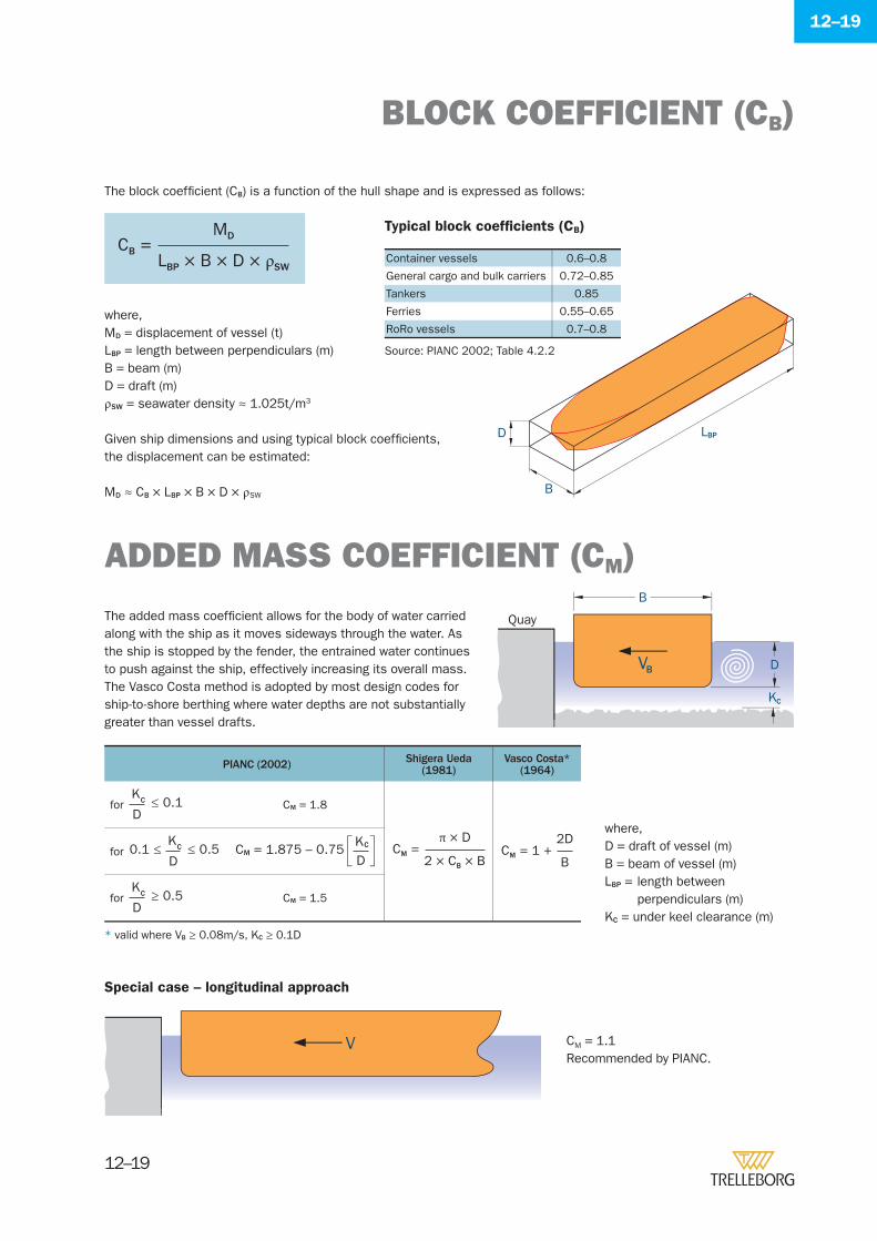
12–19
12–19
The added mass coeffi cient allows for the body of water carried along with the ship as it moves sideways through the water. As the ship is stopped by the fender, the entrained water continues to push against the ship, effectively increasing its overall mass. The Vasco Costa method is adopted by most design codes for ship-to-shore berthing where water depths are not substantially greater than vessel drafts.
The block coeffi cient (CB) is a function of the hull shape and is expressed as follows:
where,MD = displacement of vessel (t)LBP = length between perpendiculars (m)B = beam (m)D = draft (m)ρSW = seawater density ≈ 1.025t/m3
Typical block coeffi cients (CB)
Container vessels 0.6–0.8
General cargo and bulk carriers 0.72–0.85
Tankers 0.85
Ferries 0.55–0.65
RoRo vessels 0.7–0.8
D
B
LBP
B
D
Quay
KC
VB
ADDED MASS COEFFICIENT (CM)
BLOCK COEFFICIENT (CB)
PIANC (2002) Shigera Ueda(1981)
Vasco Costa*(1964)
for ≤ 0.1D
KC CM = 1.8
2 × CB × B
π × D=CM
B
2D= 1 +CMfor ≤ 0.5
D
KC0.1 ≤ CM = 1.875 – 0.75
DKC
for ≥ 0.5D
KC CM = 1.5
where,D = draft of vessel (m)B = beam of vessel (m)LBP = length between
perpendiculars (m)KC = under keel clearance (m)
Special case – longitudinal approach
V CM = 1.1Recommended by PIANC.
Given ship dimensions and using typical block coeffi cients, the displacement can be estimated:
MD ≈ CB × LBP × B × D × ρSW
* valid where VB ≥ 0.08m/s, KC ≥ 0.1D
LBP × B × D × ρSW
MD=CB
Source: PIANC 2002; Table 4.2.2
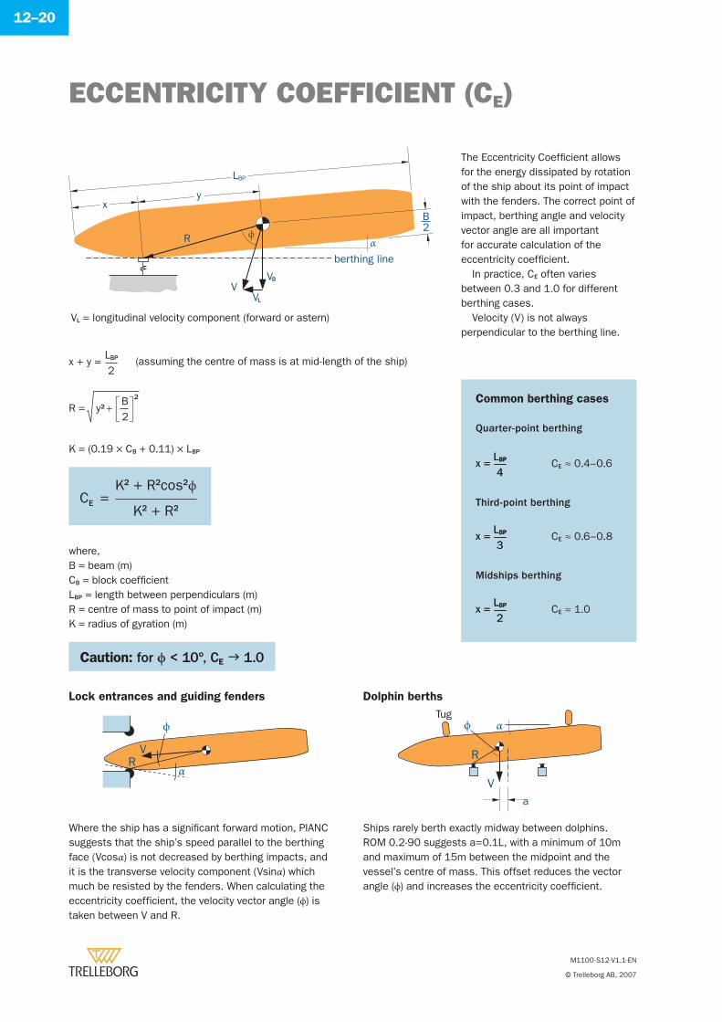
12–20
R ϕα
LBP
xy
VVL
VB
B2
berthing line
Common berthing cases
Quarter-point berthing
CE ≈ 0.4–0.6
Third-point berthing
CE ≈ 0.6–0.8
Midships berthing
CE ≈ 1.0
x = 4LBPx = 4LBP
x = 3LBPx = 3LBP
x = 2LBPx = 2LBP
Where the ship has a signifi cant forward motion, PIANC suggests that the ship’s speed parallel to the berthing face (Vcosα) is not decreased by berthing impacts, and it is the transverse velocity component (Vsinα) which much be resisted by the fenders. When calculating the eccentricity coefficient, the velocity vector angle (ϕ) is taken between V and R.
Ships rarely berth exactly midway between dolphins.ROM 0.2-90 suggests a=0.1L, with a minimum of 10m and maximum of 15m between the midpoint and the vessel’s centre of mass. This offset reduces the vector angle (ϕ) and increases the eccentricity coeffi cient.
VR
ϕ
α
αϕTug
V
R
a
M1100-S12-V1.1-EN
© Trelleborg AB, 2007
ECCENTRICITY COEFFICIENT (CE)
The Eccentricity Coeffi cient allows for the energy dissipated by rotation of the ship about its point of impact with the fenders. The correct point of impact, berthing angle and velocity vector angle are all important for accurate calculation of the eccentricity coeffi cient.
In practice, CE often varies between 0.3 and 1.0 for different berthing cases.
Velocity (V) is not always perpendicular to the berthing line.
VL = longitudinal velocity component (forward or astern)
x + y = 2LBP
2
2B
y2R +=
K = (0.19 × CB + 0.11) × LBP
where,B = beam (m)CB = block coeffi cientLBP = length between perpendiculars (m)R = centre of mass to point of impact (m)K = radius of gyration (m)
Caution: for ϕ < 10º, CE 1.0
(assuming the centre of mass is at mid-length of the ship)
K2 + R2
K2 + R2cos2ϕ=CE
Lock entrances and guiding fenders Dolphin berths
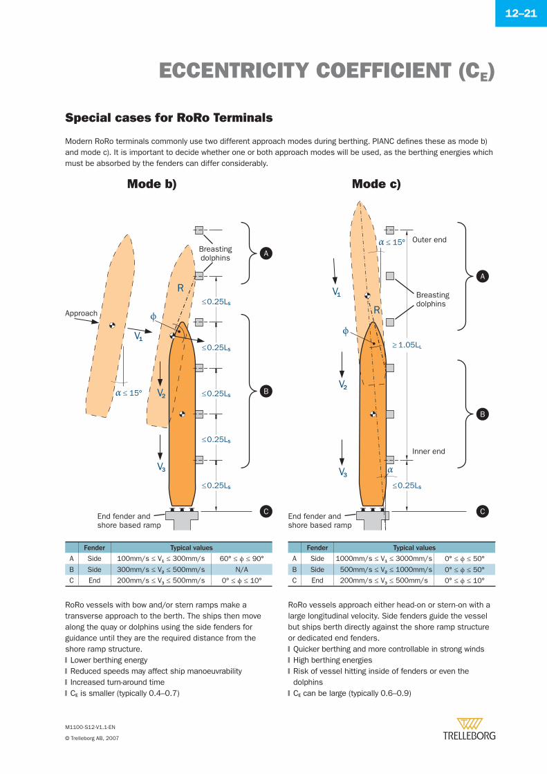
12–21
Breastingdolphins
Approach
A
B
C
α ≤ 15º
ϕ
V1
R
V2
V3
≤0.25LS
≤0.25LS
≤0.25LS
≤0.25LS
≤0.25LS
End fender andshore based ramp
R
Outer end
Inner end
α
End fender andshore based ramp
V3
V2
≤0.25LS
≥ 1.05LL
Breastingdolphins
V1
α ≤ 15º
A
B
C
ϕ
M1100-S12-V1.1-EN
© Trelleborg AB, 2007
Modern RoRo terminals commonly use two different approach modes during berthing. PIANC defi nes these as mode b) and mode c). It is important to decide whether one or both approach modes will be used, as the berthing energies which must be absorbed by the fenders can differ considerably.
Mode b) Mode c)
RoRo vessels with bow and/or stern ramps make a transverse approach to the berth. The ships then move along the quay or dolphins using the side fenders for guidance until they are the required distance from the shore ramp structure.
Lower berthing energyReduced speeds may affect ship manoeuvrabilityIncreased turn-around timeCE is smaller (typically 0.4–0.7)
�
�
�
�
RoRo vessels approach either head-on or stern-on with a large longitudinal velocity. Side fenders guide the vessel but ships berth directly against the shore ramp structure or dedicated end fenders.
Quicker berthing and more controllable in strong windsHigh berthing energiesRisk of vessel hitting inside of fenders or even the dolphinsCE can be large (typically 0.6–0.9)
�
�
�
�
ECCENTRICITY COEFFICIENT (CE)
Special cases for RoRo Terminals
Fender Typical values
A Side 100mm/s ≤ V1 ≤ 300mm/s 60° ≤ ϕ ≤ 90°
B Side 300mm/s ≤ V2 ≤ 500mm/s N/A
C End 200mm/s ≤ V3 ≤ 500mm/s 0° ≤ ϕ ≤ 10°
Fender Typical values
A Side 1000mm/s ≤ V1 ≤ 3000mm/s 0° ≤ ϕ ≤ 50°
B Side 500mm/s ≤ V2 ≤ 1000mm/s 0° ≤ ϕ ≤ 50°C End 200mm/s ≤ V3 ≤ 500mm/s 0° ≤ ϕ ≤ 10°
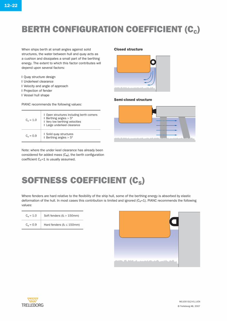
12–22
When ships berth at small angles against solid structures, the water between hull and quay acts as a cushion and dissipates a small part of the berthing energy. The extent to which this factor contributes will depend upon several factors:
SOFTNESS COEFFICIENT (CS)
Where fenders are hard relative to the fl exibility of the ship hull, some of the berthing energy is absorbed by elastic deformation of the hull. In most cases this contribution is limited and ignored (CS=1). PIANC recommends the following values:
BERTH CONFIGURATION COEFFICIENT (CC)
M1100-S12-V1.1-EN
© Trelleborg AB, 2007
CC = 1.0
Open structures including berth cornersBerthing angles > 5ºVery low berthing velocitiesLarge underkeel clearance
�
�
�
�
CC = 0.9 Solid quay structuresBerthing angles > 5º�
�
Closed structure
Semi-closed structure
Quay structure designUnderkeel clearanceVelocity and angle of approachProjection of fenderVessel hull shape
�
�
�
�
�
PIANC recommends the following values:
CS = 1.0 Soft fenders (δf > 150mm)
CS = 0.9 Hard fenders (δf ≤ 150mm)
Note: where the under keel clearance has already been considered for added mass (CM), the berth confi guration coeffi cient CC=1 is usually assumed.
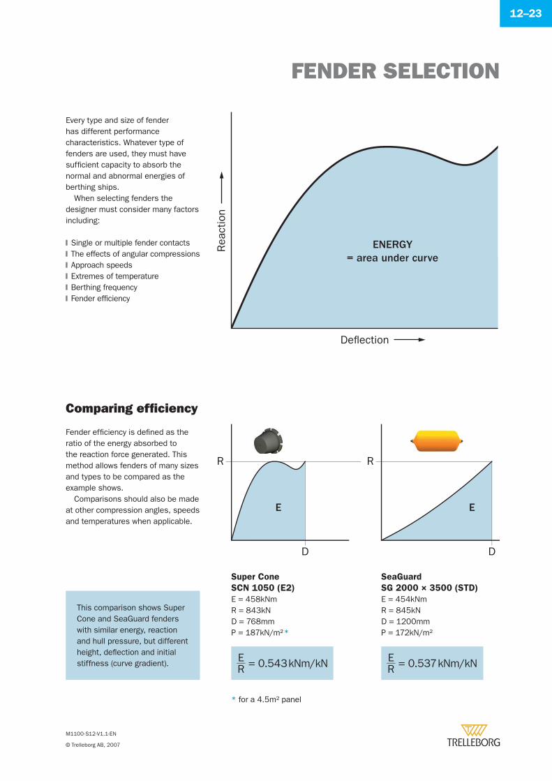
FENDER SELECTION
M1100-S12-V1.1-EN
© Trelleborg AB, 2007
12–23
Comparing effi ciency
Every type and size of fender has different performance characteristics. Whatever type of fenders are used, they must have suffi cient capacity to absorb the normal and abnormal energies of berthing ships.
When selecting fenders the designer must consider many factors including:
Single or multiple fender contactsThe effects of angular compressionsApproach speedsExtremes of temperatureBerthing frequencyFender effi ciency
�
�
�
�
�
�
Rea
ctio
n
Deflection
ENERGY= area under curve
Fender effi ciency is defi ned as the ratio of the energy absorbed to the reaction force generated. This method allows fenders of many sizes and types to be compared as the example shows.
Comparisons should also be made at other compression angles, speeds and temperatures when applicable.
R
D
E
R
D
E
Super Cone
SCN 1050 (E2)
E = 458kNmR = 843kND = 768mmP = 187kN/m2 *
SeaGuard
SG 2000 × 3500 (STD)
E = 454kNmR = 845kND = 1200mmP = 172kN/m2
E = 0.543 kNm/kNR E = 0.537 kNm/kNR
* for a 4.5m2 panel
This comparison shows Super Cone and SeaGuard fenders with similar energy, reaction and hull pressure, but different height, defl ection and initial stiffness (curve gradient).
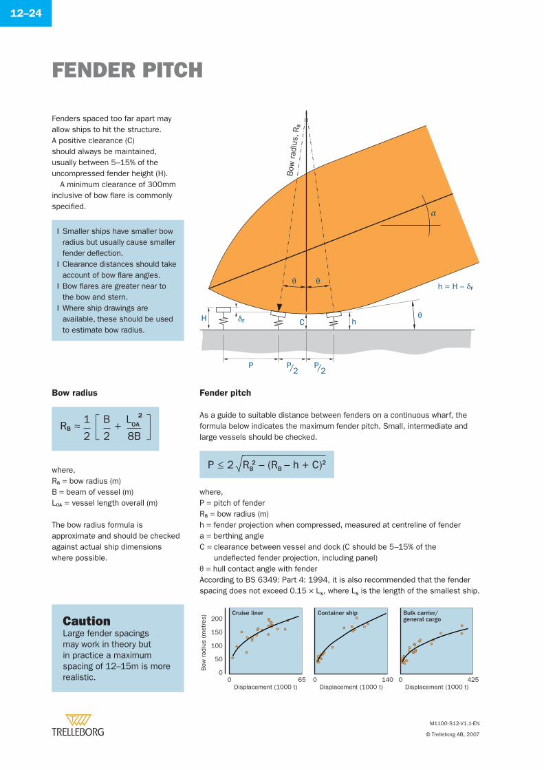
FENDER PITCH
M1100-S12-V1.1-EN
© Trelleborg AB, 2007
12–24
Fenders spaced too far apart may allow ships to hit the structure. A positive clearance (C) should always be maintained, usually between 5–15% of the uncompressed fender height (H).
A minimum clearance of 300mm inclusive of bow fl are is commonly specifi ed.
Smaller ships have smaller bow radius but usually cause smaller fender defl ection.Clearance distances should take account of bow fl are angles.Bow fl ares are greater near to the bow and stern.Where ship drawings are available, these should be used to estimate bow radius.
�
�
�
�
δF
α
θ θ
θ
P
h
h = H – δFB
ow r
adiu
s, R
B
H C
P2/
P2/
Bow radius
where,RB = bow radius (m)B = beam of vessel (m)LOA = vessel length overall (m)
Fender pitch
where,P = pitch of fenderRB = bow radius (m)h = fender projection when compressed, measured at centreline of fendera = berthing angleC = clearance between vessel and dock (C should be 5–15% of the
undefl ected fender projection, including panel)θ = hull contact angle with fender
As a guide to suitable distance between fenders on a continuous wharf, the formula below indicates the maximum fender pitch. Small, intermediate and large vessels should be checked.
According to BS 6349: Part 4: 1994, it is also recommended that the fender spacing does not exceed 0.15 × LS, where LS is the length of the smallest ship.
CautionLarge fender spacings may work in theory but in practice a maximum spacing of 12–15m is more realistic.
00 65 0 140 0 425
Displacement (1000 t) Displacement (1000 t) Displacement (1000 t)
Bow
rad
ius
(met
res)
50
100
150
200Cruise liner Container ship Bulk carrier/
general cargo
RB ≈ +8B
LOA
2
2
1
2
B
P ≤ 2 RB2 – (RB – h + C)2
The bow radius formula is approximate and should be checked against actual ship dimensions where possible.
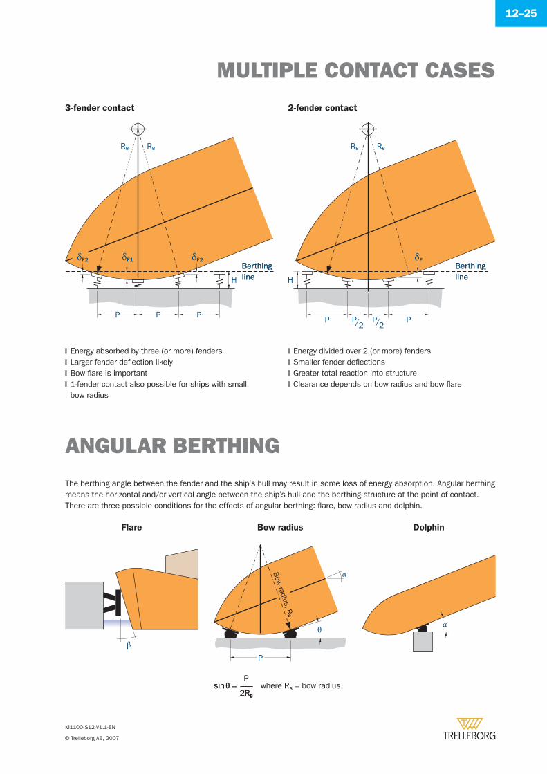
MULTIPLE CONTACT CASES
M1100-S12-V1.1-EN
© Trelleborg AB, 2007
12–25
Flare Bow radius Dolphin
β
θ
α
P
Bow
radius, RB
α
where RB = bow radius2RB
P=sinθ
2RB
P=sinθ
Energy absorbed by three (or more) fendersLarger fender defl ection likelyBow fl are is important1-fender contact also possible for ships with smallbow radius
�
�
�
�
Energy divided over 2 (or more) fendersSmaller fender defl ectionsGreater total reaction into structureClearance depends on bow radius and bow fl are
�
�
�
�
3-fender contact 2-fender contact
ANGULAR BERTHING
The berthing angle between the fender and the ship’s hull may result in some loss of energy absorption. Angular berthing means the horizontal and/or vertical angle between the ship’s hull and the berthing structure at the point of contact.There are three possible conditions for the effects of angular berthing: fl are, bow radius and dolphin.
P P
H
BerthinglineBerthingline
BerthinglineBerthingline
P
RB RB
P P
δFδF2δF2 δF1
RB RB
P2/
P2/
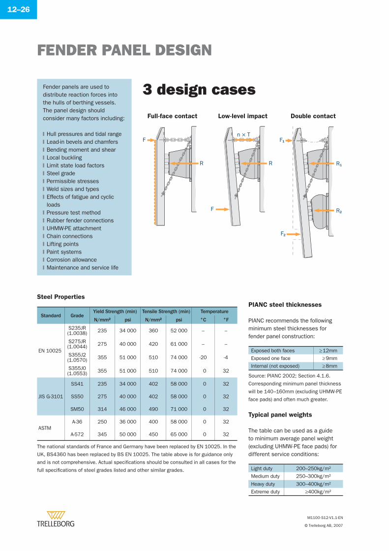
FENDER PANEL DESIGN
M1100-S12-V1.1-EN
© Trelleborg AB, 2007
12–26
Fender panels are used to distribute reaction forces into the hulls of berthing vessels. The panel design should consider many factors including:
Hull pressures and tidal rangeLead-in bevels and chamfersBending moment and shearLocal bucklingLimit state load factorsSteel gradePermissible stressesWeld sizes and typesEffects of fatigue and cyclic loadsPressure test methodRubber fender connectionsUHMW-PE attachmentChain connectionsLifting pointsPaint systemsCorrosion allowanceMaintenance and service life
�
�
�
�
�
�
�
�
�
�
�
�
�
�
�
�
�
3 design cases
Full-face contact Low-level impact Double contact
F
F
R R R1
R2
n × TF1
F2
The national standards of France and Germany have been replaced by EN 10025. In the
UK, BS4360 has been replaced by BS EN 10025. The table above is for guidance only
and is not comprehensive. Actual specifi cations should be consulted in all cases for the
full specifi cations of steel grades listed and other similar grades.
PIANC steel thicknesses
PIANC recommends the following minimum steel thicknesses for fender panel construction:
Exposed both faces ≥ 12mm
Exposed one face ≥ 9mm
Internal (not exposed) ≥ 8mm
Corresponding minimum panel thickness
will be 140–160mm (excluding UHMW-PE
face pads) and often much greater.
Typical panel weights
The table can be used as a guide to minimum average panel weight (excluding UHMW-PE face pads) for different service conditions:
Light duty 200–250kg/m2
Medium duty 250–300kg/m2
Heavy duty 300–400kg/m2
Extreme duty ≥400kg/m2
Steel Properties
Standard GradeYield Strength (min) Tensile Strength (min) Temperature
N/mm² psi N/mm² psi °C °F
EN 10025
S235JR(1.0038) 235 34 000 360 52 000 – –
S275JR(1.0044) 275 40 000 420 61 000 – –
S355J2(1.0570) 355 51 000 510 74 000 -20 -4
S355J0(1.0553) 355 51 000 510 74 000 0 32
JIS G-3101
SS41 235 34 000 402 58 000 0 32
SS50 275 40 000 402 58 000 0 32
SM50 314 46 000 490 71 000 0 32
ASTMA-36 250 36 000 400 58 000 0 32
A-572 345 50 000 450 65 000 0 32
Source: PIANC 2002; Section 4.1.6.
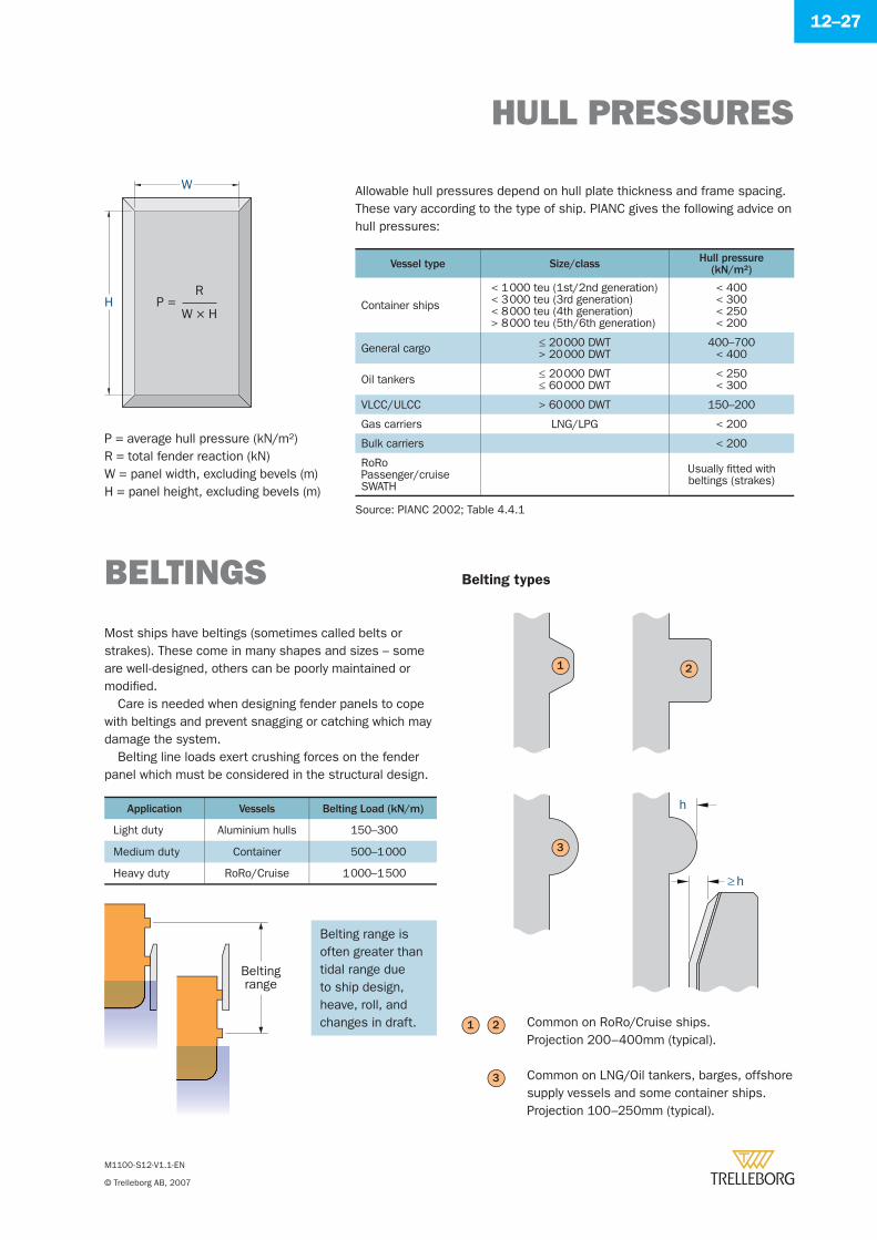
HULL PRESSURES
M1100-S12-V1.1-EN
© Trelleborg AB, 2007
12–27
Allowable hull pressures depend on hull plate thickness and frame spacing. These vary according to the type of ship. PIANC gives the following advice on hull pressures:
Vessel type Size/class Hull pressure(kN/m2)
Container ships
< 1 000 teu (1st/2nd generation)< 3 000 teu (3rd generation)< 8 000 teu (4th generation)> 8 000 teu (5th/6th generation)
< 400< 300< 250< 200
General cargo ≤ 20 000 DWT> 20 000 DWT
400–700< 400
Oil tankers ≤ 20 000 DWT≤ 60 000 DWT
< 250< 300
VLCC/ULCC > 60 000 DWT 150–200
Gas carriers LNG/LPG < 200
Bulk carriers < 200
RoRoPassenger/cruiseSWATH
Usually fi tted withbeltings (strakes)
P = average hull pressure (kN/m2)R = total fender reaction (kN)W = panel width, excluding bevels (m)H = panel height, excluding bevels (m)
W
HW × H
RP =
BELTINGS
Most ships have beltings (sometimes called belts or strakes). These come in many shapes and sizes – some are well-designed, others can be poorly maintained or modifi ed.
Care is needed when designing fender panels to cope with beltings and prevent snagging or catching which may damage the system.
Belting line loads exert crushing forces on the fender panel which must be considered in the structural design.
Belting range is often greater than tidal range due to ship design, heave, roll, and changes in draft.
Application Vessels Belting Load (kN/m)
Light duty Aluminium hulls 150–300
Medium duty Container 500–1 000
Heavy duty RoRo/Cruise 1 000–1 500
Belting types
≥h
h
3
1 2
3
Common on RoRo/Cruise ships.Projection 200–400mm (typical).
Common on LNG/Oil tankers, barges, offshore supply vessels and some container ships. Projection 100–250mm (typical).
1 2
Beltingrange
Source: PIANC 2002; Table 4.4.1
FRICTION
M1100-S12-V1.1-EN
© Trelleborg AB, 2007
12–28
SWL =n cosθμR + W
Friction has a large infl uence on the fender design, particularly for restraint chains. Low friction facing materials (UHMW-PE) are often used to reduce friction. Other materials, like polyurethanes (PU) used for the skin of foam fenders, have lower friction coeffi cients than rubber against steel or concrete.
The table can be used as a guide to typical design values. Friction coeffi cients may vary due to wet or dry conditions, local temperatures, static and dynamic load cases, as well as surface roughness.
Materials Friction Coeffi cient (μ)
UHMW-PE Steel 0.2
HD-PE Steel 0.3
Polyurethane Steel 0.4
Rubber Steel 0.7
Timber Steel 0.4
Steel Steel 0.5
CHAIN DESIGN
Chains can be used to restrain the movements of fenders during compression or to support static loads. Chains may serve four main functions:
Weight chains support the steel panel and prevent excessive drooping of the system. They may also resist vertical shear forces caused by ship movements or changing draft.Shear chains resist horizontal forces caused during longitudinal approaches or warping operations.Tension chains restrict tension on the fender rubber. Correct location can optimise the defl ection geometry.Keep chains are used to moor fl oating fenders or to prevent loss of fi xed fenders in the event of accidents.
�
�
�
�
Factors to be considered when designing fender chains:
Corrosion reduces link diameter and weakens the chain.Corrosion allowances and periodic replacement should be allowed for.A ‘weak link’ in the chain system is desirable to prevent damage to more costly components in an accident.
�
�
�
3
Tension chains
Weight chains
Shear chains
1
2
3
1
θ
μR
W
where,SWL = safe working load (kN)FC = safety factorμ = coeffi cient of frictionR = fender reaction (kN)W = gross panel weight (kg)(for shear chains, W = 0)n = number of chainsθ = effective chain angle (degrees)
2
Typical friction design values
MBL ≥ FC × SWL
UHMW-PE FACING
M1100-S12-V1.1-EN
© Trelleborg AB, 2007
12–29
Always use oversize washers to spread the load.
The contact face of a fender panel helps to determine the lifetime maintenance costs of a fender installation. UHMW-PE (FQ1000) is the best material available for such applications. It uniquely combines low friction, impact strength, non-marking characteristics and resistance to wear, temperature extremes, seawater and marine borers.
Sinter moulded into plates at extremely high pressure, UHMW-PE is a totally homogeneous material which is available in many sizes and thicknesses. These plates can be cut, machined and drilled to suit any type of panel or shield.
Fastening example
Large pads vs small pads
Larger pads are usually more robust but smaller pads are easier and cheaper to replace.
Application t (mm) W* (mm) Bolt
Light duty 30 3–5 M16
Medium duty40 7–10
M16–M2050 10–15
Heavy duty
60 15–19
M24–M3070 18–25
80 22–32
Extreme duty90 25–36
M30–M36100 28–40
t
W
* Where allowances are typical values, actual wear allowance may vary due fi xing detail.
The standard colour is black, but UHMW-PE is available in many other colours if
CORROSION PREVENTION
M1100-S12-V1.1-EN
© Trelleborg AB, 2007
12–30
Fenders are usually installed in corrosive environments, sometimes made worse by high temperature and humidity. Corrosion of fender accessories can be reduced with specialist paint coatings, by galvanising or with selective use of stainless steels.
Paint coatings and galvanising have a fi nite life. Coating must be reapplied at intervals during the life of the fender. Galvanised components like chains or bolts may need periodic re-galvanising or replacement. Stainless steels should be carefully selected for their performance in seawater.
ISO EN 12944 is a widely used international standard defi ning the durability of corrosion protection systems in various environments. The C5-M class applies to marine coastal, offshore and high salinity locations and is considered to be the most applicable to fenders.
The life expectancy or ‘durability’ of coatings is divided into three categories which estimate the time to fi rst major maintenance:
Paint coatings
Low 2–5 years
Medium 5–15 years
High >15 years
Durability range is not a guarantee. It is to help operators estimate sensible maintenance times.
PaintSystem
Surface Preparation
Priming Coat(s) Top Coats Paint System Expected durability (C5-M corrosivity)Binder Primer No. coats NDFT Binder No. coats NDFT No. coats NDFT
S7.09 Sa 2.5 EP, PUR Zn (R) 1 40 EP, PUR 3-4 280 4-5 320 High (>15y)
S7.11 Sa 2.5 EP, PUR Zn (R) 1 40 CTE 3 360 4 400 High (>15y)
S7.16 Sa 2.5 CTE Misc 1 100 CTE 2 200 3 300 Medium (5-15y)
Sa 2.5 is defi ned in ISO 8501-1
NDFT = Nominal dry fi lm thickness
Zn (R) = Zinc rich primer
Misc = miscellaneous types of
anticorrosive pigments
EP = 2-pack epoxy
PUR = 1-pack or 2-pack polyurethane
CTE = 2-pack coal tar epoxy
Design considerations
Other paint systems may also satisfy the C5-M requirements but in choosing any coating the designer should carefully consider the following:
Corrosion protection systems are not a substitute for poor design details such as re-entrant shapes and corrosion traps.Minimum dry fi lm thickness >80% of NDFT (typical)Maximum fi lm thickness <3 × NDFT (typical)Local legislation on emission of solvents or health & safety factorsApplication temperatures, drying and handling timesMaximum over-coating timesLocal conditions including humidity or contaminants
Refer to paint manufacturer for advice on specifi c applications and products.
�
�
�
�
�
�
�
The table gives some typical C5-M class paint systems which provide high durability in marine environments. Note that coal tar epoxy paints are not available in some countries.
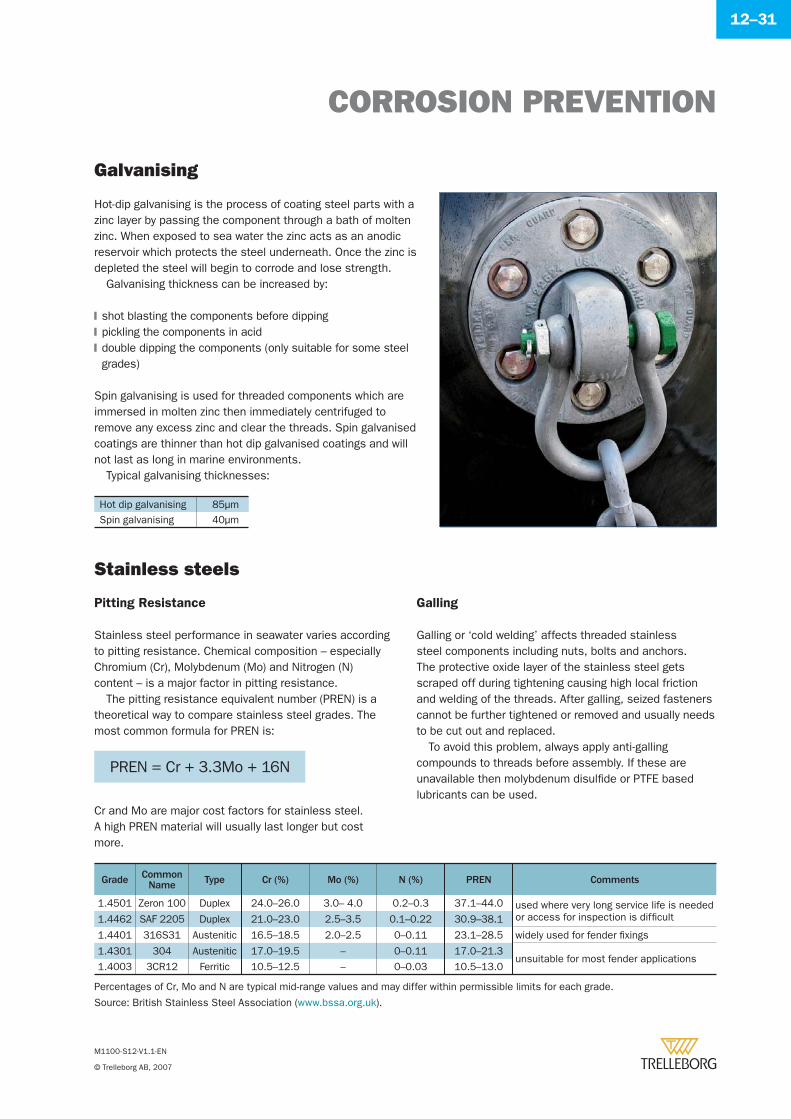
CORROSION PREVENTION
M1100-S12-V1.1-EN
© Trelleborg AB, 2007
12–31
Galvanising
Hot-dip galvanising is the process of coating steel parts with a zinc layer by passing the component through a bath of molten zinc. When exposed to sea water the zinc acts as an anodic reservoir which protects the steel underneath. Once the zinc is depleted the steel will begin to corrode and lose strength.
Galvanising thickness can be increased by:
shot blasting the components before dippingpickling the components in aciddouble dipping the components (only suitable for some steel grades)
Spin galvanising is used for threaded components which are immersed in molten zinc then immediately centrifuged to remove any excess zinc and clear the threads. Spin galvanised coatings are thinner than hot dip galvanised coatings and will not last as long in marine environments.
Typical galvanising thicknesses:
�
�
�
Hot dip galvanising 85μmSpin galvanising 40μm
Stainless steels
Percentages of Cr, Mo and N are typical mid-range values and may differ within permissible limits for each grade.
Source: British Stainless Steel Association (www.bssa.org.uk).
Grade Common Name Type Cr (%) Mo (%) N (%) PREN Comments
1.4501 Zeron 100 Duplex 24.0–26.0 3.0– 4.0 0.2–0.3 37.1–44.0 used where very long service life is neededor access for inspection is diffi cult1.4462 SAF 2205 Duplex 21.0–23.0 2.5–3.5 0.1–0.22 30.9–38.1
1.4401 316S31 Austenitic 16.5–18.5 2.0–2.5 0–0.11 23.1–28.5 widely used for fender fi xings
1.4301 304 Austenitic 17.0–19.5 – 0–0.11 17.0–21.3unsuitable for most fender applications
1.4003 3CR12 Ferritic 10.5–12.5 – 0–0.03 10.5–13.0
Pitting Resistance
Stainless steel performance in seawater varies according to pitting resistance. Chemical composition – especially Chromium (Cr), Molybdenum (Mo) and Nitrogen (N) content – is a major factor in pitting resistance.
The pitting resistance equivalent number (PREN) is a theoretical way to compare stainless steel grades. The most common formula for PREN is:
PREN = Cr + 3.3Mo + 16N
Cr and Mo are major cost factors for stainless steel. A high PREN material will usually last longer but cost more.
Galling
Galling or ‘cold welding’ affects threaded stainless steel components including nuts, bolts and anchors. The protective oxide layer of the stainless steel gets scraped off during tightening causing high local friction and welding of the threads. After galling, seized fasteners cannot be further tightened or removed and usually needs to be cut out and replaced.
To avoid this problem, always apply anti-galling compounds to threads before assembly. If these are unavailable then molybdenum disulfi de or PTFE based lubricants can be used.
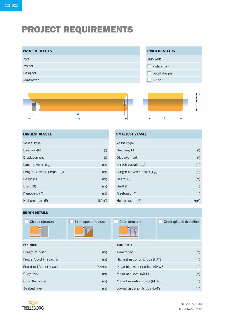
PROJECT REQUIREMENTS
M1100-S12-V1.1-EN
© Trelleborg AB, 2007
12–32
PROJECT DETAILS
Port
Project
Designer
Contractor
PROJECT STATUS
TMS Ref:
Preliminary
Detail design
Tender
LARGEST VESSEL
Vessel type
Deadweight (t)
Displacement (t)
Length overall (LOA) (m)
Length between perps (LBP) (m)
Beam (B) (m)
Draft (D) (m)
Freeboard (F) (m)
Hull pressure (P) (t/m2)
SMALLEST VESSEL
Vessel type
Deadweight (t)
Displacement (t)
Length overall (LOA) (m)
Length between perps (LBP) (m)
Beam (B) (m)
Draft (D) (m)
Freeboard (F) (m)
Hull pressure (P) (t/m2)
BERTH DETAILS
Structure Tide levels
Length of berth (m) Tidal range (m)
Fender/dolphin spacing (m) Highest astronomic tide (HAT) (m)
Permitted fender reaction (kN/m) Mean high water spring (MHWS) (m)
Quay level (m) Mean sea level (MSL) (m)
Cope thickness (m) Mean low water spring (MLWS) (m)
Seabed level (m) Lowest astronomic tide (LAT) (m)
LBP
LOA B
D
F
Closed structure Semi-open structure Open structure Other (please describe)
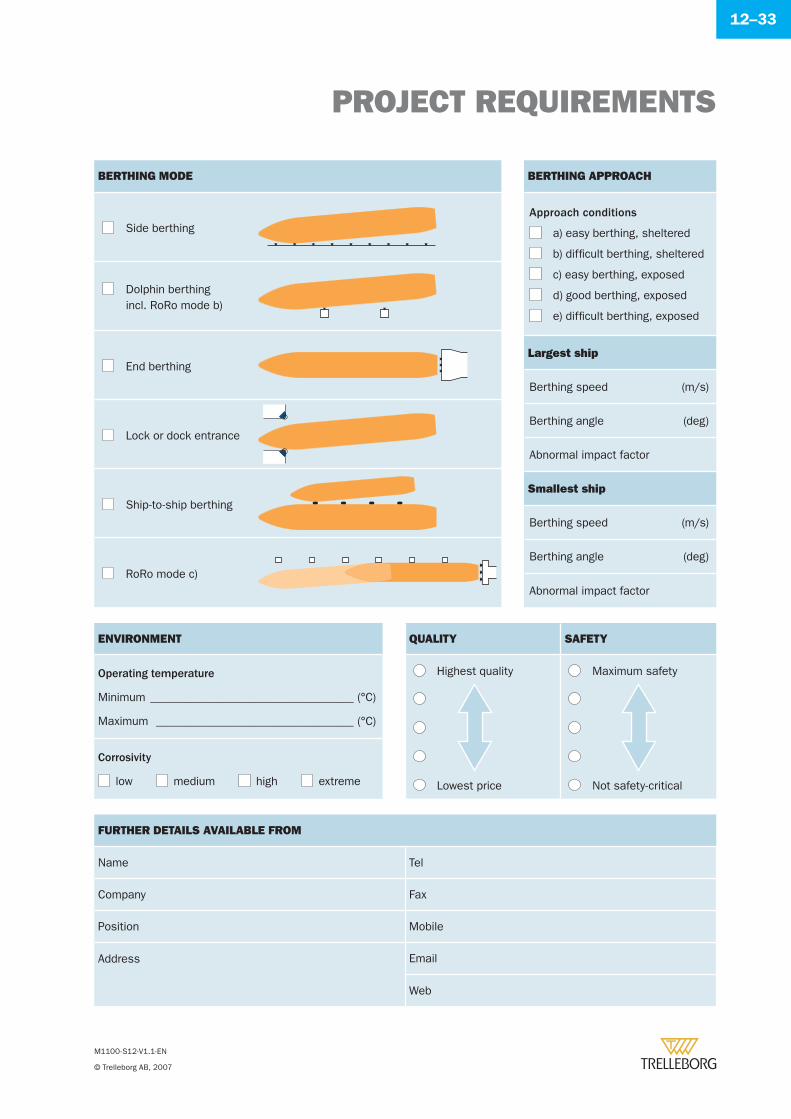
PROJECT REQUIREMENTS
M1100-S12-V1.1-EN
© Trelleborg AB, 2007
12–33
BERTHING MODE
Side berthing
Dolphin berthing incl. RoRo mode b)
End berthing
Lock or dock entrance
Ship-to-ship berthing
RoRo mode c)
BERTHING APPROACH
Approach conditions
a) easy berthing, sheltered
b) diffi cult berthing, sheltered
c) easy berthing, exposed
d) good berthing, exposed
e) diffi cult berthing, exposed
Largest ship
Berthing speed (m/s)
Berthing angle (deg)
Abnormal impact factor
Smallest ship
Berthing speed (m/s)
Berthing angle (deg)
Abnormal impact factor
ENVIRONMENT
Operating temperature
Minimum ___________________________________ (°C)
Maximum __________________________________ (°C)
Corrosivity
low medium high extreme
FURTHER DETAILS AVAILABLE FROM
Name Tel
Company Fax
Position Mobile
Address Email
Web
QUALITY SAFETY
Highest quality Maximum safety
Lowest price Not safety-critical
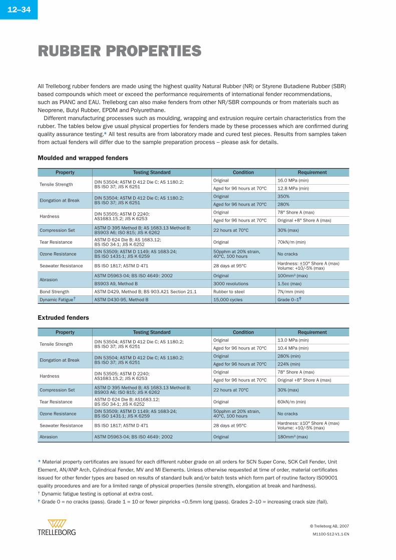
RUBBER PROPERTIES
© Trelleborg AB, 2007
M1100-S12-V1.1-EN
12–34
All Trelleborg rubber fenders are made using the highest quality Natural Rubber (NR) or Styrene Butadiene Rubber (SBR) based compounds which meet or exceed the performance requirements of international fender recommendations, such as PIANC and EAU. Trelleborg can also make fenders from other NR/SBR compounds or from materials such as Neoprene, Butyl Rubber, EPDM and Polyurethane.
Different manufacturing processes such as moulding, wrapping and extrusion require certain characteristics from the rubber. The tables below give usual physical properties for fenders made by these processes which are confi rmed during quality assurance testing.* All test results are from laboratory made and cured test pieces. Results from samples taken from actual fenders will differ due to the sample preparation process – please ask for details.
Moulded and wrapped fenders
Property Testing Standard Condition Requirement
Tensile Strength DIN 53504; ASTM D 412 Die C; AS 1180.2; BS ISO 37; JIS K 6251
Original 16.0 MPa (min)
Aged for 96 hours at 70ºC 12.8 MPa (min)
Elongation at Break DIN 53504; ASTM D 412 Die C; AS 1180.2; BS ISO 37; JIS K 6251
Original 350%
Aged for 96 hours at 70ºC 280%
Hardness DIN 53505; ASTM D 2240; AS1683.15.2; JIS K 6253
Original 78° Shore A (max)
Aged for 96 hours at 70ºC Original +8° Shore A (max)
Compression Set ASTM D 395 Method B; AS 1683.13 Method B; BS903 A6; ISO 815; JIS K 6262 22 hours at 70°C 30% (max)
Tear Resistance ASTM D 624 Die B; AS 1683.12; BS ISO 34-1; JIS K 6252 Original 70kN/m (min)
Ozone Resistance DIN 53509; ASTM D 1149; AS 1683-24; BS ISO 1431-1; JIS K 6259
50pphm at 20% strain,40°C, 100 hours No cracks
Seawater Resistance BS ISO 1817; ASTM D 471 28 days at 95°C Hardness: ±10° Shore A (max)Volume: +10/-5% (max)
AbrasionASTM D5963-04; BS ISO 4649 : 2002 Original 100mm3 (max)
BS903 A9, Method B 3000 revolutions 1.5cc (max)
Bond Strength ASTM D429, Method B; BS 903.A21 Section 21.1 Rubber to steel 7N/mm (min)
Dynamic Fatigue† ASTM D430-95, Method B 15,000 cycles Grade 0–1‡
Property Testing Standard Condition Requirement
Tensile Strength DIN 53504; ASTM D 412 Die C; AS 1180.2; BS ISO 37; JIS K 6251
Original 13.0 MPa (min)
Aged for 96 hours at 70ºC 10.4 MPa (min)
Elongation at Break DIN 53504; ASTM D 412 Die C; AS 1180.2; BS ISO 37; JIS K 6251
Original 280% (min)
Aged for 96 hours at 70ºC 224% (min)
Hardness DIN 53505; ASTM D 2240; AS1683.15.2; JIS K 6253
Original 78° Shore A (max)
Aged for 96 hours at 70ºC Original +8° Shore A (max)
Compression Set ASTM D 395 Method B; AS 1683.13 Method B; BS903 A6; ISO 815; JIS K 6262 22 hours at 70°C 30% (max)
Tear Resistance ASTM D 624 Die B; AS1683.12; BS ISO 34-1; JIS K 6252 Original 60kN/m (min)
Ozone Resistance DIN 53509; ASTM D 1149; AS 1683-24; BS ISO 1431-1; JIS K 6259
50pphm at 20% strain,40°C, 100 hours No cracks
Seawater Resistance BS ISO 1817; ASTM D 471 28 days at 95°C Hardness: ±10° Shore A (max)Volume: +10/-5% (max)
Abrasion ASTM D5963-04; BS ISO 4649 : 2002 Original 180mm3 (max)
Extruded fenders
* Material property certifi cates are issued for each different rubber grade on all orders for SCN Super Cone, SCK Cell Fender, Unit
Element, AN/ANP Arch, Cylindrical Fender, MV and MI Elements. Unless otherwise requested at time of order, material certifi cates
issued for other fender types are based on results of standard bulk and/or batch tests which form part of routine factory ISO9001
quality procedures and are for a limited range of physical properties (tensile strength, elongation at break and hardness).† Dynamic fatigue testing is optional at extra cost.‡ Grade 0 = no cracks (pass). Grade 1 = 10 or fewer pinpricks <0.5mm long (pass). Grades 2–10 = increasing crack size (fail).
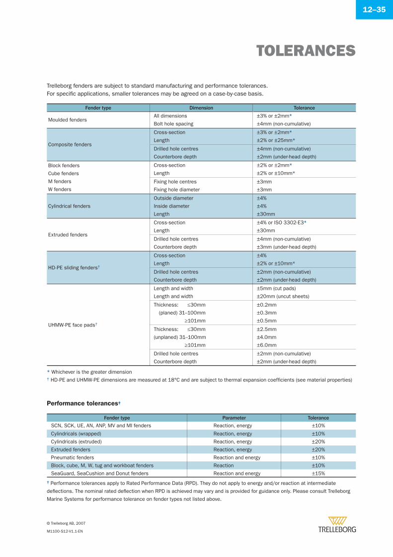
TOLERANCES
© Trelleborg AB, 2007
M1100-S12-V1.1-EN
12–35
Trelleborg fenders are subject to standard manufacturing and performance tolerances.For specifi c applications, smaller tolerances may be agreed on a case-by-case basis.
Fender type Dimension Tolerance
Moulded fendersAll dimensions
Bolt hole spacing
±3% or ±2mm*
±4mm (non-cumulative)
Composite fenders
Cross-section
Length
±3% or ±2mm*
±2% or ±25mm*
Drilled hole centres
Counterbore depth
±4mm (non-cumulative)
±2mm (under-head depth)
Block fenders
Cube fenders
M fenders
W fenders
Cross-section
Length
±2% or ±2mm*
±2% or ±10mm*
Fixing hole centres
Fixing hole diameter
±3mm
±3mm
Cylindrical fenders
Outside diameter
Inside diameter
Length
±4%
±4%
±30mm
Extruded fenders
Cross-section
Length
±4% or ISO 3302-E3*
±30mm
Drilled hole centres
Counterbore depth
±4mm (non-cumulative)
±3mm (under-head depth)
HD-PE sliding fenders†
Cross-section
Length
±4%
±2% or ±10mm*
Drilled hole centres
Counterbore depth
±2mm (non-cumulative)
±2mm (under-head depth)
UHMW-PE face pads†
Length and width
Length and width
±5mm (cut pads)
±20mm (uncut sheets)
Thickness: ≤30mm
(planed) 31–100mm
≥101mm
±0.2mm
±0.3mm
±0.5mm
Thickness: ≤30mm
(unplaned) 31–100mm
≥101mm
±2.5mm
±4.0mm
±6.0mm
Drilled hole centres
Counterbore depth
±2mm (non-cumulative)
±2mm (under-head depth)
‡ Performance tolerances apply to Rated Performance Data (RPD). They do not apply to energy and/or reaction at intermediate
defl ections. The nominal rated defl ection when RPD is achieved may vary and is provided for guidance only. Please consult Trelleborg
Marine Systems for performance tolerance on fender types not listed above.
Performance tolerances‡
Fender type Parameter Tolerance
SCN, SCK, UE, AN, ANP, MV and MI fenders Reaction, energy ±10%
Cylindricals (wrapped) Reaction, energy ±10%
Cylindricals (extruded) Reaction, energy ±20%
Extruded fenders Reaction, energy ±20%
Pneumatic fenders Reaction and energy ±10%
Block, cube, M, W, tug and workboat fenders Reaction ±10%
SeaGuard, SeaCushion and Donut fenders Reaction and energy ±15%
* Whichever is the greater dimension† HD-PE and UHMW-PE dimensions are measured at 18°C and are subject to thermal expansion coeffi cients (see material properties)
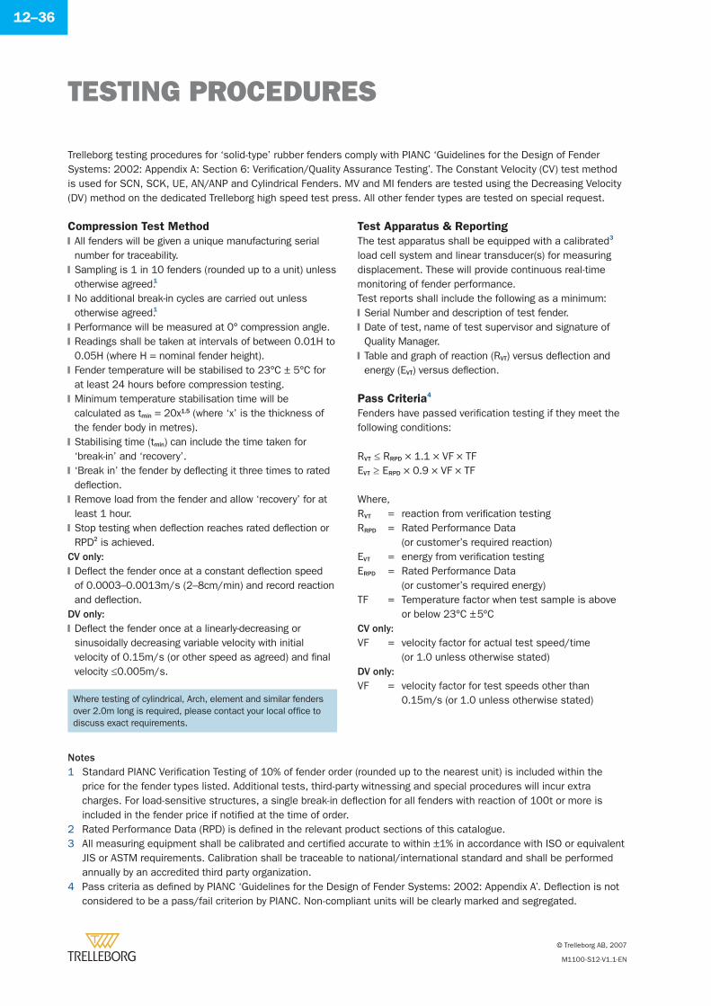
TESTING PROCEDURES
© Trelleborg AB, 2007
M1100-S12-V1.1-EN
12–36
Compression Test Method
All fenders will be given a unique manufacturing serial number for traceability.Sampling is 1 in 10 fenders (rounded up to a unit) unless otherwise agreed.1
No additional break-in cycles are carried out unless otherwise agreed.1
Performance will be measured at 0° compression angle.Readings shall be taken at intervals of between 0.01H to 0.05H (where H = nominal fender height).Fender temperature will be stabilised to 23°C ± 5°C for at least 24 hours before compression testing.Minimum temperature stabilisation time will be calculated as tmin = 20x1.5 (where ‘x’ is the thickness of the fender body in metres).Stabilising time (tmin) can include the time taken for ‘break-in’ and ‘recovery’.‘Break in’ the fender by defl ecting it three times to rated defl ection.Remove load from the fender and allow ‘recovery’ for at least 1 hour.Stop testing when defl ection reaches rated defl ection or RPD2 is achieved.
�
�
�
�
�
�
�
�
�
�
�
NotesStandard PIANC Verifi cation Testing of 10% of fender order (rounded up to the nearest unit) is included within the price for the fender types listed. Additional tests, third-party witnessing and special procedures will incur extra charges. For load-sensitive structures, a single break-in defl ection for all fenders with reaction of 100t or more is included in the fender price if notifi ed at the time of order.Rated Performance Data (RPD) is defi ned in the relevant product sections of this catalogue.All measuring equipment shall be calibrated and certifi ed accurate to within ±1% in accordance with ISO or equivalent JIS or ASTM requirements. Calibration shall be traceable to national/international standard and shall be performed annually by an accredited third party organization.Pass criteria as defi ned by PIANC ‘Guidelines for the Design of Fender Systems: 2002: Appendix A’. Defl ection is not considered to be a pass/fail criterion by PIANC. Non-compliant units will be clearly marked and segregated.
1
2 3
4
Trelleborg testing procedures for ‘solid-type’ rubber fenders comply with PIANC ‘Guidelines for the Design of Fender Systems: 2002: Appendix A: Section 6: Verifi cation/Quality Assurance Testing’. The Constant Velocity (CV) test method is used for SCN, SCK, UE, AN/ANP and Cylindrical Fenders. MV and MI fenders are tested using the Decreasing Velocity (DV) method on the dedicated Trelleborg high speed test press. All other fender types are tested on special request.
CV only:Defl ect the fender once at a constant defl ection speed of 0.0003–0.0013m/s (2–8cm/min) and record reaction and defl ection.
�
DV only:Defl ect the fender once at a linearly-decreasing or sinusoidally decreasing variable velocity with initial velocity of 0.15m/s (or other speed as agreed) and fi nal velocity ≤0.005m/s.
�
Test Apparatus & Reporting
The test apparatus shall be equipped with a calibrated3 load cell system and linear transducer(s) for measuring displacement. These will provide continuous real-time monitoring of fender performance.Test reports shall include the following as a minimum:
Serial Number and description of test fender.Date of test, name of test supervisor and signature of Quality Manager.Table and graph of reaction (RVT) versus defl ection and energy (EVT) versus defl ection.
Pass Criteria4
Fenders have passed verifi cation testing if they meet the following conditions:
RVT ≤ RRPD × 1.1 × VF × TFEVT ≥ ERPD × 0.9 × VF × TF
Where,RVT = reaction from verifi cation testingRRPD = Rated Performance Data
(or customer’s required reaction)EVT = energy from verifi cation testingERPD = Rated Performance Data
(or customer’s required energy)TF = Temperature factor when test sample is above
or below 23ºC ± 5ºCCV only:VF = velocity factor for actual test speed/time
(or 1.0 unless otherwise stated)DV only:VF = velocity factor for test speeds other than
0.15m/s (or 1.0 unless otherwise stated)
�
�
�
Where testing of cylindrical, Arch, element and similar fenders over 2.0m long is required, please contact your local offi ce to discuss exact requirements.
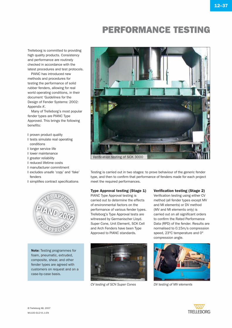
PERFORMANCE TESTING
© Trelleborg AB, 2007
M1100-S12-V1.1-EN
12–37
Trelleborg is committed to providing high quality products. Consistency and performance are routinely checked in accordance with the latest procedures and test protocols.
PIANC has introduced new methods and procedures for testing the performance of solid rubber fenders, allowing for real world operating conditions, in their document ‘Guidelines for the Design of Fender Systems: 2002: Appendix A’.
Many of Trelleborg’s most popular fender types are PIANC Type Approved. This brings the following benefi ts:
proven product qualitytests simulate real operating conditionslonger service lifelower maintenancegreater reliabilityreduced lifetime costsmanufacturer commitmentexcludes unsafe ‘copy’ and ‘fake’ fenderssimplifi es contract specifi cations
�
�
�
�
�
�
�
�
�
Testing is carried out in two stages: to prove behaviour of the generic fender type, and then to confi rm that performance of fenders made for each project meet the required performances.
Verifi cation testing (Stage 2)
Verifi cation testing using either CV method (all fender types except MV and MI elements) or DV method (MV and MI elements only) is carried out on all signifi cant orders to confi rm the Rated Performance Data (RPD) of the fender. Results are normalised to 0.15m/s compression speed, 23°C temperature and 0° compression angle.
Type Approval testing (Stage 1)
PIANC Type Approval testing is carried out to determine the effects of environmental factors on the performance of various fender types. Trelleborg’s Type Approval tests are witnessed by Germanischer Lloyd. Super Cone, Unit Element, SCK Cell and Arch Fenders have been Type Approved to PIANC standards.
DV testing of MV elementsCV testing of SCN Super Cones
Note: Testing programmes for foam, pneumatic, extruded, composite, shear, and other fender types are agreed with customers on request and on a case-by-case basis.
Verifi cation testing of SCK 3000
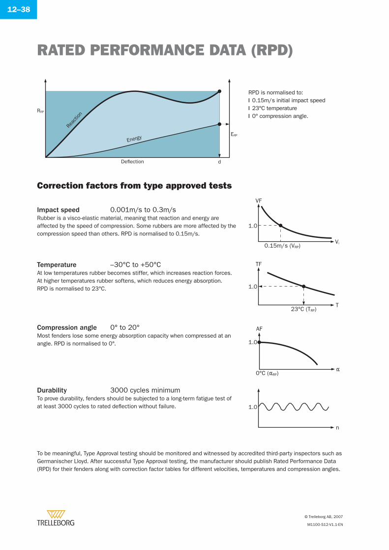
RATED PERFORMANCE DATA (RPD)
© Trelleborg AB, 2007
M1100-S12-V1.1-EN
12–38
Temperature –30°C to +50°CAt low temperatures rubber becomes stiffer, which increases reaction forces. At higher temperatures rubber softens, which reduces energy absorption.RPD is normalised to 23°C.
To be meaningful, Type Approval testing should be monitored and witnessed by accredited third-party inspectors such as Germanischer Lloyd. After successful Type Approval testing, the manufacturer should publish Rated Performance Data (RPD) for their fenders along with correction factor tables for different velocities, temperatures and compression angles.
VF
Vi
1.0
0.15m/s (VRP)
TF
T
1.0
23°C (TRP)
AF
α
1.0
0°C (αRP)
n
1.0
Impact speed 0.001m/s to 0.3m/sRubber is a visco-elastic material, meaning that reaction and energy are affected by the speed of compression. Some rubbers are more affected by the compression speed than others. RPD is normalised to 0.15m/s.
Compression angle 0° to 20°Most fenders lose some energy absorption capacity when compressed at an angle. RPD is normalised to 0°.
Durability 3000 cycles minimumTo prove durability, fenders should be subjected to a long-term fatigue test of at least 3000 cycles to rated defl ection without failure.
Correction factors from type approved tests
d
ERP
RRP
Deflection
Energy
Reac
tion
RPD is normalised to:0.15m/s initial impact speed23°C temperature0° compression angle.
�
�
�
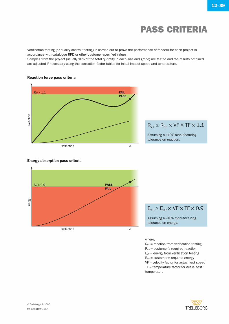
PASS CRITERIA
© Trelleborg AB, 2007
M1100-S12-V1.1-EN
12–39
Verifi cation testing (or quality control testing) is carried out to prove the performance of fenders for each project in accordance with catalogue RPD or other customer-specifi ed values.Samples from the project (usually 10% of the total quantity in each size and grade) are tested and the results obtained are adjusted if necessary using the correction factor tables for initial impact speed and temperature.
Deflection
Rea
ctio
n
d
RRP x 1.1 FAIL
PASS
Deflection
Ener
gy
d
ERP x 0.9FAIL
PASS
where,RVT = reaction from verifi cation testingRRP = customer’s required reactionEVT = energy from verifi cation testingERP = customer’s required energyVF = velocity factor for actual test speedTF = temperature factor for actual test temperature
Reaction force pass criteria
Energy absorption pass criteria
RVT ≤ RRP × VF × TF × 1.1
Assuming a +10% manufacturing tolerance on reaction.
EVT ≥ ERP × VF × TF × 0.9
Assuming a –10% manufacturing tolerance on energy.
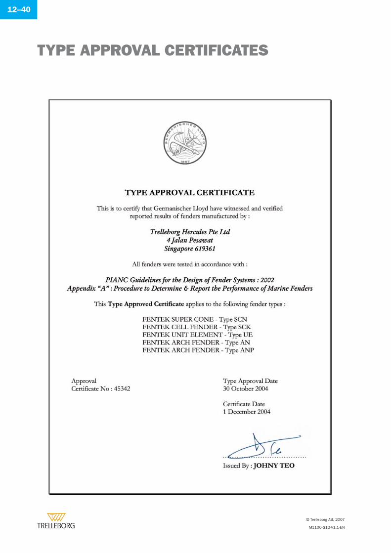
TYPE APPROVAL CERTIFICATES
© Trelleborg AB, 2007
M1100-S12-V1.1-EN
12–40
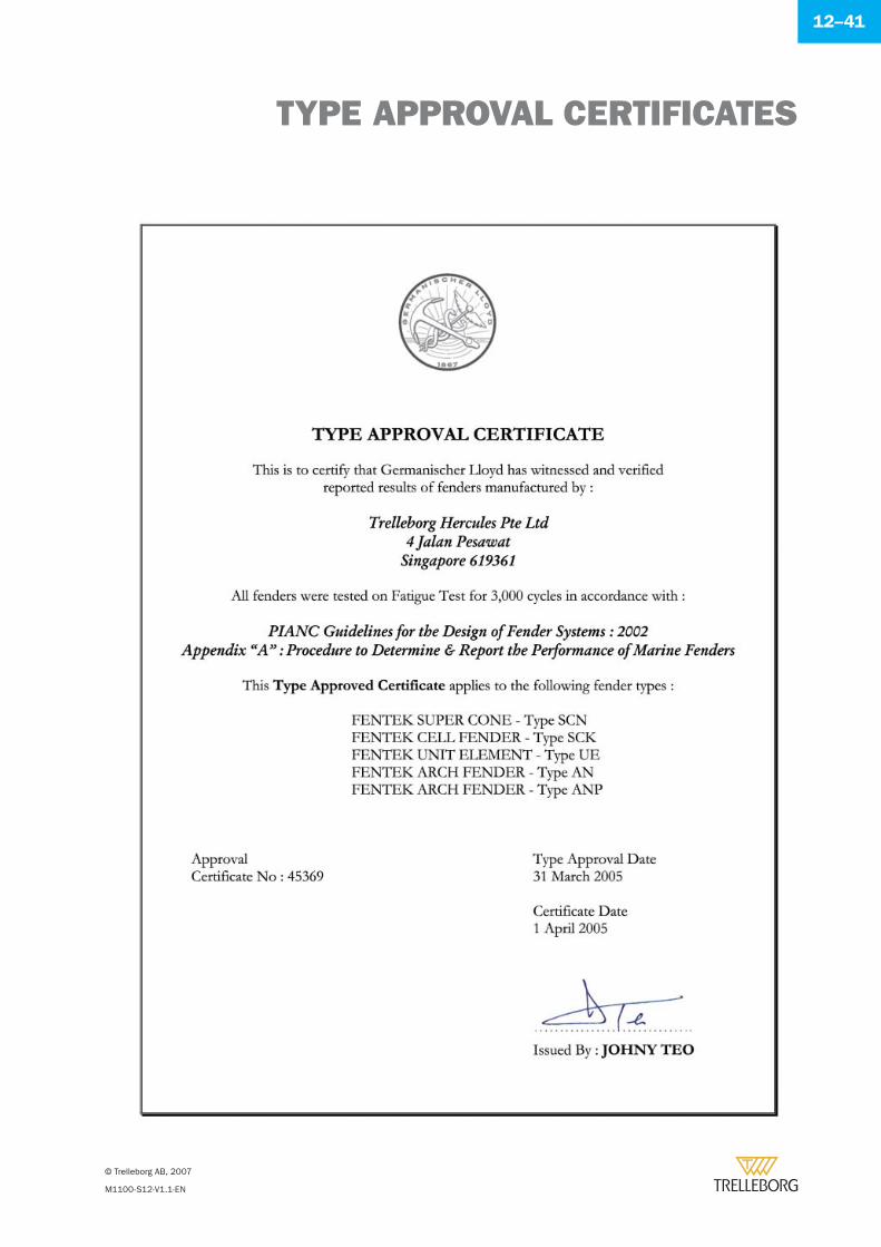
TYPE APPROVAL CERTIFICATES
© Trelleborg AB, 2007
M1100-S12-V1.1-EN
12–41
QUALITY DOCUMENTS
© Trelleborg AB, 2007
M1100-S12-V1.1-EN
12–42
Customers should expect to receive appropriate documents to prove the quality of the fenders and accessories ordered. A comprehensive document package might include:
Quality and environmental
Factory ISO 9001: 2000 quality management systemFactory ISO 14001: 2004 environmental management system
Literature and data sheets
Printed brochures or leafl ets for the supplied productsPIANC correction tables (where applicable)PIANC Type Approval certifi cates (where applicable)
Performance tests
Verifi cation test results and curves for each fender testedThird party witness certifi cate (optional but recommended)Certifi cate of conformity
Physical properties
Laboratory report for hardness, tensile strength and elongation at break, before and after ageingDurability test report (optional but recommended)Wear, tear and ozone resistance test reportsThird party witness certifi cate (optional but recommended)Certifi cate of conformity
Steel fabrications
Mill certifi catesWelder qualifi cation certifi catesWeld proceduresDimensional check report (including fl atness for panels)NDT inspection report – minimum 5% MPI (optional but recommended)Pressure (leak) test inspection reportPaint application report (temperature, humidity, dew point, etc)Dry fi lm thickness test reportCertifi cate of conformity
�
�
�
�
�
�
�
�
�
�
�
�
�
�
�
�
�
�
�
�
�
�
Fixing accessories
Mill certifi catesVisual inspection reportCertifi cate of conformity
Chains
Proof load testMill certifi cates (optional but recommended)Galvanising certifi cateDimensional inspection report (where applicable)Certifi cate of conformity
Low friction pads
Dimensional inspection reportCertifi cate of conformity
Other
As built drawingsInstallation, operation and maintenance manualInspection logbookWarranty certifi cateGeneral certifi cate of conformityAfter-sales contact details
�
�
�
�
�
�
�
�
�
�
�
�
�
�
�
�
The accuracy and authenticity of quality documents is very important. Trelleborg will provide an original or certifi ed copy of any third party report on request.
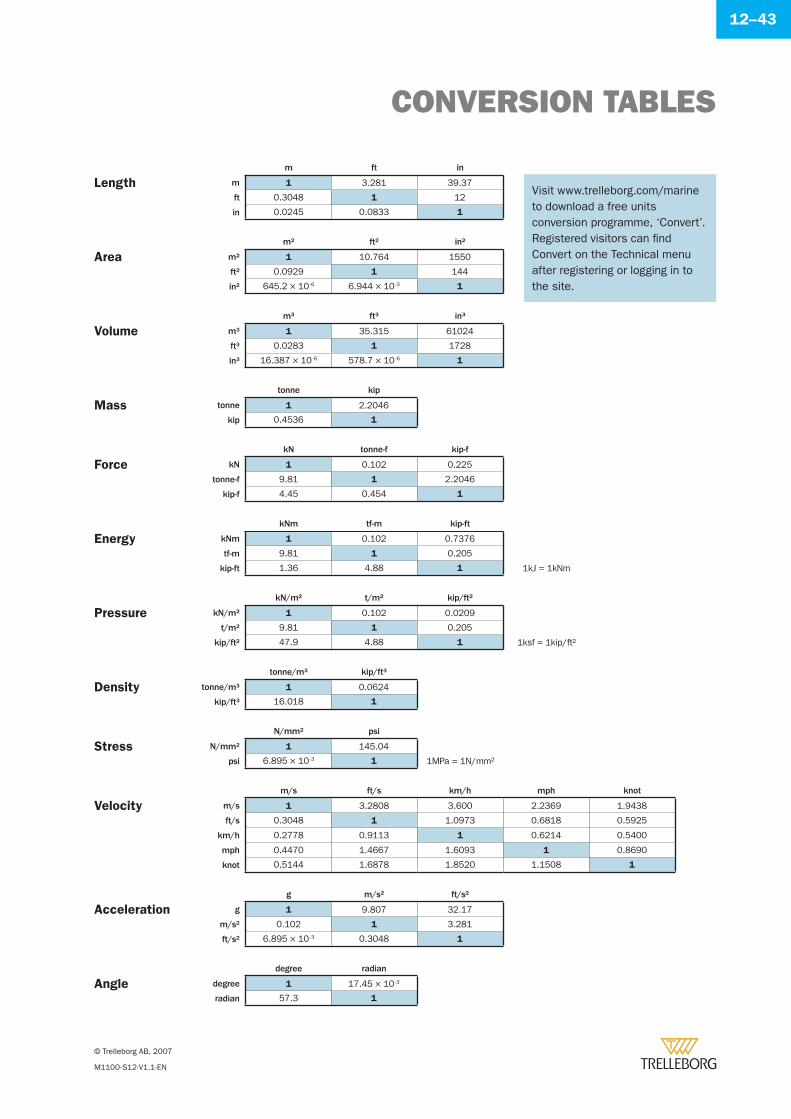
CONVERSION TABLES
© Trelleborg AB, 2007
M1100-S12-V1.1-EN
12–43
m ft in
Length m 1 3.281 39.37
ft 0.3048 1 12
in 0.0245 0.0833 1
m2 ft2 in2
Area m2 1 10.764 1550
ft2 0.0929 1 144
in2 645.2 × 10 -6 6.944 × 10 -3 1
m3 ft3 in3
Volume m3 1 35.315 61024
ft3 0.0283 1 1728
in3 16.387 × 10 -6 578.7 × 10 -6 1
tonne kip
Mass tonne 1 2.2046
kip 0.4536 1
kN tonne-f kip-f
Force kN 1 0.102 0.225
tonne-f 9.81 1 2.2046
kip-f 4.45 0.454 1
kNm tf-m kip-ft
Energy kNm 1 0.102 0.7376
tf-m 9.81 1 0.205
kip-ft 1.36 4.88 1 1kJ = 1kNm
kN/m2 t/m2 kip/ft2
Pressure kN/m2 1 0.102 0.0209
t/m2 9.81 1 0.205
kip/ft2 47.9 4.88 1 1ksf = 1kip/ft2
tonne/m3 kip/ft3
Density tonne/m3 1 0.0624
kip/ft3 16.018 1
N/mm2 psi
Stress N/mm2 1 145.04
psi 6.895 × 10 -3 1 1MPa = 1N/mm2
m/s ft/s km/h mph knot
Velocity m/s 1 3.2808 3.600 2.2369 1.9438
ft/s 0.3048 1 1.0973 0.6818 0.5925
km/h 0.2778 0.9113 1 0.6214 0.5400
mph 0.4470 1.4667 1.6093 1 0.8690
knot 0.5144 1.6878 1.8520 1.1508 1
g m/s2 ft/s2
Acceleration g 1 9.807 32.17
m/s2 0.102 1 3.281
ft/s2 6.895 × 10 -3 0.3048 1
degree radian
Angle degree 1 17.45 × 10 -3
radian 57.3 1
Visit www.trelleborg.com/marine to download a free units conversion programme, ‘Convert’. Registered visitors can fi nd Convert on the Technical menu after registering or logging in to the site.
CALCULATIONS
© Trelleborg AB, 2007
M1100-S12-V1.1-EN
12–44
Project Prepared
Title Date
Client Sheet NºRef
TRELLEBORG MARINE SYSTEMS
www.trelleborg.com/marine
CALCULATIONS
© Trelleborg AB, 2007
M1100-S12-V1.1-EN
12–45
Project Prepared
Title Date
Client Sheet NºRef
TRELLEBORG MARINE SYSTEMS
www.trelleborg.com/marine
© Trelleborg AB, 2007
M1100-S12-V1.1-EN
12–46
Disclaimer
Trelleborg AB has made every effort to ensure that the technical specifi cations and product descriptions in this catalogue are correct.
The responsibility or liability for errors and omissions cannot be accepted for any reason whatsoever. Customers are advised to request a detailed specifi cation and certifi ed drawing prior to construction and manufacture. In the interests of improving the quality and performance of our products and systems, we reserve the right to make specifi cation changes without prior notice. All dimensions, material properties and performance values quoted are subject to normal production and testing tolerances. This catalogue supersedes the information provided in all previous editions. If in doubt, please check with Trelleborg Marine Systems.
© Trelleborg AB, PO Box 153, 231 22 Trelleborg, Sweden.This catalogue is the copyright of Trelleborg AB and may not be reproduced, copied or distributed to third parties without the prior consent of Trelleborg AB in each case.Fentek, Rubbylene and Orkot are Registered Trade Marks of Trelleborg AB.
Designed by Harrison Sigala(www.harrisonsigala.com)

© Trelleborg AB, 2007
M1100-S12-V1.1-EN
12–47
In 2005, the Trelleborg Group celebrated its centenary. To us, quality is a state of mind. We adopt an in-depth approach to each problem, aiming for long-term solutions.Yesterday’s and today’s innovations, know-how and quality form the foundation of tomorrow.
Trelleborg is a global industrial group whose
leading positions are based on advanced polymer
technology and in-depth applications know-how.
We develop high-performance solutions that
seal, damp and protect in demanding industrial
environments.
The Group has annual sales of approximately
€3 billion, with about 24,000 employees in 40
countries. The head offi ce is located in Trelleborg,
Sweden.
Trelleborg AB was founded in 1905. With 100
years behind us, our history, like our future, is
characterised by a constant drive for quality and
a passion for identifying new solution to complex
problems.
Four business areas
Trelleborg Engineered Systems is a leading global supplier of engineered solutions that focus on the sealing, protection and safety of investments, processes and individuals in extremely demanding environments.
Trelleborg Automotive is a world-leader in the development and production of polymer-based components and systems used for noise and vibration damping for passenger car and light and heavy trucks.
Trelleborg Sealing Solutions is a leading global supplier of precision seals for the industrial, aerospace and automotive markets.
Trelleborg Wheel Systems is a leading global supplier of tires and complete wheel systems for farm and forest machinery, forklift trucks and other materials-handling vehicles.
Presented by
www.trelleborg.com/[email protected]
AmericasTel: +1 540 667 [email protected]
AsiaTel: +65 6268 [email protected]
AustraliaTel: +61 2 9285 [email protected]
BeneluxTel: +31 180 [email protected]
Central AsiaTel: +91 79 4003 [email protected]
FranceTel: +33 1 41 39 22 [email protected]
GermanyTel: +49 40 600 [email protected]
Japan
Tel: +81 3 3512 1981
Middle East
Tel: +971 4 886 1825
Scandinavia
Tel: +46 410 51 667
Spain
Tel: +34 945 437 906
UK
Tel: +44 1666 827660
Harbour Marine
Tel: +61 3 9575 9999
Ref
. M110
0-V
1.1
-EN