Embed Size (px)
Citation preview

Navigation
TravelPilot DX-N7 612 001 460 Black monitor7 612 001 461 Upgrade without monitor7 612 001 462 Silver monitor
Installation instructions

2Safety precautions
Congratulations on your purchase of this Blaupunkt product. Thank you for the trust you are putting into our brand!
The following installation instructions are intended to help you getting the best performance from your Blaupunkt product. To avoid theaggravation of costly mistakes and serious damage to your system, please read all of the instructions carefully before you begin.. Ifyou’re not confident that you can install the unit correctly, have it installed by a qualified Blaupunkt installation technician.
Installation and connection regulations
While connecting and installing this equipment, make sure to disconnect the negative terminal of the battery.
Important!
Observe all safety precautions provided by the automobile manufacturer (alarm systems, immobilisers, airbag)!Before drilling the holes for mounting and wiring, make sure that no existing wiring or vehicle parts will be damaged(e.g. petrol tank, petrol lines).Use wire bushings for all sharp-edged holes.To avoid interference, make sure to lay the wiring far enough away from the wire harness.Attach a fuse to the positive supply wire at a maximum of 30 cm from the battery to protect the battery and the positivesupply wire in the event of a short circuit.
The navigation equipment is suitable for vehicles with:• 12 V battery power• Negative pole on the vehicle body
AnhangAllgemeines Kurzanlei- TourenZieleingabe Zielspeicher Einstellun-3
Contents
Important installationinformation for thespeedometer signal ............7Connecting the speedometersignal .................................................... 7
Connecting the back-uplights signal wire .................7
Video input assignment......8
System testafter installation ..................8
Calibration ...........................9Calibrating the Gala curve ................. 9
Technical data ...................10Basic navigation unit ....................... 10
5" colour display ............................... 10
What’s includedin the delivery ....................11
Safety precautions ..............2
Installation ...........................4Description .......................................... 4
Notes on how the system functions ... 4
Installation preparations .................... 4
Installingthe navigation unit ..............5Where to install the navigation unit .... 5
Positive connection ............................ 5
Negative connection .......................... 5
Installing the GPS antenna ..5
Installing the display...........6Safety instructions ............................. 6
Display installation ............................. 6
Display de-installation ....................... 6
Installing the speaker .........6
Installing the control unit ...7
Assembly illustrations ..... 16
Connecting the sensors .. 18DX-N and RC 09Hin the front ......................................... 18
Connecting the sensors .. 19DX-N in the car boot,TMC tuner box andRC 09H in the front ........................... 19

4Installation
Description
The TravelPilot DX-N navigation system is an independent sys-tem with an integrated gyroscope. After a destination has beenentered and activated, the system delivers visual driving recom-mendations as pictograms on a 5" colour monitor and spokendriving information via a separate speaker well in advance ofany turns or changes in driving direction required. In this way,the system guides the motorist from his/her starting point on thebest route to the selected destination.All of the available functions are described in the specificationsof the CD-ROM used.
Notes on how the system functions
The TravelPilot is equipped with an automatic calibrationfeature which is required to determine the current vehicleposition. Depending on the GPS reception available, thecalibration is completed after the vehicle has been drivenapprox. 15 km. Driving along a winding route (in the city),which is indicated on the monitor on a map, accelerates thecalibration.
The speedometer signal connection in the vehicle allows thesystem to determine the distance driven. If there is no speed-ometer signal, it will be necessary to have a route sensor in-stalled by an authorised customer service centre.In this case, you will have to order a sensor kit (route sen-sor, magnet strips, bracket, plug and installation instruc-tions) from your dealer.Order No.: 7 607 611 093
Installation preparations
Before starting the installation, check to see thatno parts from the installation pack are missing. ........ page 11
The following steps must be completed to install the equipment:
• Installing the navigation unit (computer) .......... page 5• Installing the GPS antenna ................................. page 5• Installing the display (monitor) .......................... page 6• Installing the speaker .......................................... page 6• Installing the operating unit ............................... page 7• Installing the speedometer signal wire ............. page 7• Installing the back-up lights signal wire ........... page 7
AnhangAllgemeines Kurzanlei- TourenZieleingabe Zielspeicher Einstellun-5
Installation
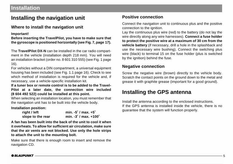
Installing the navigation unit
Where to install the navigation unit
Important!Before inserting the TravelPilot, you have to make sure thatthe gyroscope is positioned horizontally (see Fig. 7, page 17).
The TravelPilot DX-N can be installed in the car radio compart-ment in the vehicle (installation depth 218 mm). You will needan installation bracket (order no. 8 601 310 555) (see Fig. 1 page16).For vehicles without a DIN compartment, a universal equipmenthousing has been included (see Fig. 1.1 page 16). Check to seewhich method of installation is required for the vehicle and, ifnecessary, use a vehicle-specific installation kit.If a tuner box or remote control is to be added to the Travel-Pilot at a later date, the connection wire included(8 604 492 522) could be installed at this point.When selecting an installation location, you must remember thatthe navigation unit has to be built into the vehicle body.
Installation position:right / left min. -5˚ / max. +5˚slope to the rear min. -3˚ / max. +100˚
A fan has been built into the back of the unit to cool it whenit overheats. To allow for sufficient air circulation, make surethat the air vents are not blocked. Use only the hole stripsto attach the unit to the mounting bolt.
Make sure that there is enough room to insert and remove thenavigation CD.
Positive connection
Connect the navigation unit to continuous plus and the positiveconnection to the ignition.Lay the continuous plus wire (red) to the battery (do not lay thewire directly along any wire harnesses). Connect a fuse holderto protect the positive wire at a maximum of 30 cm from thevehicle battery (if necessary, drill a hole in the splashback anduse the necessary wire bushing). Connect the switching pluswire (black) to terminal 15 on the fuse holder (plus is switchedby the ignition) behind the fuse.
Negative connection
Screw the negative wire (brown) directly to the vehicle body.Scratch the contact points on the ground down to the metal andgrease it with graphite grease (important for a good ground).
Installing the GPS antenna
Install the antenna according to the enclosed instructions.If the GPS antenna is installed inside the vehicle, there is noguarantee that the system will function properly.

6Installation
Installing the display
Safety instructions
Never grease or oil the ball-and-socket joint.The monitor cable must be laid so that it is not subjectedto any tensile strains or other loads.
Important!Do not mount the monitor within the inflation range ofthe airbags (on the driver’s side, the passenger side orthe side airbags) or where it might strike the head or kneesof anyone in the vehicle in the event of an accident!
Before drilling the holes for the mounting screws andwiring, make sure that no damage will be done to cov-ered wiring, the petrol tank or fuel lines!
Display installation
Fig. 3 The display is mounted on the dashboard or console us-ing the enclosed ball-and-socket base.
Fig. 4 The display is mounted directly on a console (telephoneconsole) with the ball joint.
Fig. 5 The display is mounted using the swan neck fitting 7 612001 204 and the ball-and-socket base. To do so, you mustdisassemble the rear panel of the display.A 10 mm wide hole must be drilled at the mounting posi-tion to accommodate the cable. When the cable is in-stalled, you must ensure it will safe from being tugged orstretched or from being exposed to any other loads.
Display de-installation (Fig. 6)
1. Unscrew the four screws on the back of the display and re-move the rear panel.
2. Pull out the plugs carefully and push them through the mount-ing base.
3. Then use the mounting material you require.
Installing the speaker
Install the speaker used for the spoken driving recommenda-tions in the footwell of the vehicle.
Important!Make sure that the vehicle operating elements remain easilyaccessible and are not obstructed in any way by the connectioncable and the location of the speaker (gear stick, hand brake,accelerator, clutch or brake pedals, etc.)!
Important!Before drilling the holes for the mounting screws, make sure thatno damage will be done to covered wiring, the petrol tank or fuellines!

AnhangAllgemeines Kurzanlei- TourenZieleingabe Zielspeicher Einstellun-7
Installing the control unit
Mount the control unit bracket in a location where the controlunit will be easily accessible, e.g. on the centre console.
Important!Do not mount the control unit within the inflation range of theairbags (on the driver’s side, the passenger side or the side air-bags) or where it might strike the head or knees of anyone in thevehicle in the event of an accident!Before drilling the holes for the mounting screws, make sure thatno damage will be done to covered wiring, the petrol tank or fuellines!Make sure that the vehicle operating elements remain easilyaccessible and are not obstructed in any way (gear stick, handbrake, etc.)!
Important installation information forthe speedometer signal
When connecting the speedometer signal, make sure toobserve the following information:
1. Where to find the signal: For many vehicles, the speedom-eter signal can be found in the vehicle-specific car radio plug.Contact the customer service of the vehicle manufacturer oran authorised navigation dealer to find out what the exact pinallocation is.
2. Do not use the speedometer signal from ABS control units orcontrol circuits.
Installation
3. Important:We assume no responsibility for any equipment that is in-stalled incorrectly and the consequences thereof!
Connecting the speedometer signal
Important: This connection should be made by an authorisedcustomer service centre.
The connection is made with the speedometer signal wire(8 618 841 988) to the vehicle-specific speedometer signal con-nection. (see connection diagram, page 18).
Connecting the back-up lights signalwire
Important : This connection should be made by an authorisedcustomer service centre.
The connection is made with the back-up lights signal wire(8 618 842 033) to the vehicle back-up lights. Make sure thatthere are +12V at the connection when the vehicle is backing up(see connection diagram, page 18).
Important:We assume no responsibility for any equipment that is installedincorrectly and the consequences thereof!

8Installation
Video input assignment
The video input socket is intended for future applications. Forinformation on connection options, please contact a Blaupunktdealer or our hotline. See connection diagram for assignment.
Description Input /Ouput
CommentPin
EXT_R E
Low = PAL Format / High = NTSC Format
1
2
3
4
5
6
7
8
9
10
11
12
13
14
15
EXT_G
EXT_B
V_GND
EXT_SYNC
NC
U14
STANDARD SWITCH
EARTH
NC
N. B.
Switch on EXT.
UB
Screen switch
MP_U53
Low = Off / High = On
E
E
E
E
-
A
E
A
E
A
A
A
Low = Mirror image / High = Normal image
Red input
Green input
Blue input
Synchronisation input
Video earth
1
15
10
System test after installation
The system test allows you to test the external connections tosee that they are working correctly.
Proceed as follows:
1. Turn off TravelPilot DX-N
2. Press the button and keep it pressed.
3. Turn on the TravelPilot DX-N and release the button whenthe service menu appears.
4. Using the button, select the test menu and press theOK button.
5. Now select the required test using the or button, pressthe OK button and follow the on-screen instructions.
If the test was completed successfully, the menu item will belabelled with a tick. If an error occurs, an appropriate noticewill be displayed.
6. Close the service menu by pressing the button.

AnhangAllgemeines Kurzanlei- TourenZieleingabe Zielspeicher Einstellun-9
Calibration
Calibration
After installation, the TravelPilot DX-N must be calibrated. Youwill find the procedure for this described in the operating instruc-tions.
Calibrating the Gala curve
After the TravelPilot DX-N is calibrated, the values that weredetermined must be transferred to the control unit software sothat the Gala feature (sound-dependent volume adjustment)works correctly.
Please proceed as follows:
1. Turn off TravelPilot DX-N.
2. Press the button and keep it pressed.
3. Turn on the TravelPilot DX-N and release the button whenthe service menu appears.
4. Using the button, select the settings menu and pressthe OK button. This procedure transfers the calibration val-ues that were previously determined to the control unit.
5. Close the service menu by pressing the button.

10Technical data
Basic navigation unit
Rated voltage (Urat) 14 V / DC
Rated current (I) Typically 0.55 A (Imax 1.05 A)
Stand-by current Typically 0.35 A
Speech output /volume Max. 3 Watt/4 Ohm
Time to first positioncomputation (Warm start, memory refresh)
< 2 minutes; (cold start, memoryclear) < 15 minutes
CD-ROM drive For 12 cm CD to DIN EN 60908only
Operating temperature -15°C to +60°C
Mounting orientation right / leftmin. - 5˚ / max. + 5˚slope to the rearmin. - 3˚ / max. +100˚
Width 187.5 mm
Height 58.5 mm
Depth 174.4 mm
Weight 1.35 kg
5" colour display
TFT active matrix LCD (12.5 cm diagonal)
Contrast control Manual on rocker
Brightness control Automatic by phototransistor,manual on rocker
Mounting Universal ball-and-socket joint
Width 148 mm (without cable and base)
Height 105 mm (without cable and base)
Depth 51 mm (without cable and base)
Cable length 5.5 m
Subject to modification!

AnhangAllgemeines Kurzanlei- TourenZieleingabe Zielspeicher Einstellun-11
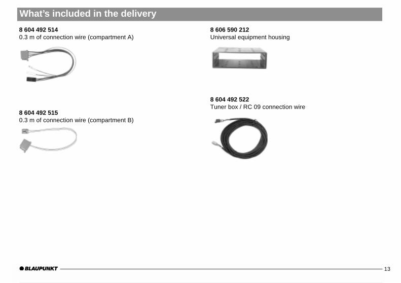
What’s included in the delivery
TravelPilot DX-N 7 612 001 460 / 7 612 001 462
7 612 001 489Navigation unit with integrated gyroscope and GPS receiver
8 627 000 013GPS-antenna
8 618 842 735 5"- colour monitor black8 618 842 667 5"- colour monitor silver
8 618 842 586Speaker
8 618 840 7544 m of wire for the speaker
8 601 360 105Operating unit incl. bracket and IR sensor (eye)

12What’s included in the delivery
8 618 841 4126 m of DC wire
8 618 842 0334.5 m of back-up lights signal wire
8 618 841 9884 m of speedometer wire
8 604 492 5130.3 m of connection wire (compartment C1)
blue
yellow
white
brown
AnhangAllgemeines Kurzanlei- TourenZieleingabe Zielspeicher Einstellun-13
What’s included in the delivery
8 604 492 5140.3 m of connection wire (compartment A)
8 604 492 5150.3 m of connection wire (compartment B)
8 606 590 212Universal equipment housing
8 604 492 522Tuner box / RC 09 connection wire

14What’s included in the delivery
TravelPilot DX-N 7 612 001 461
7 612 001 489Navigation unit with integrated gyroscope and GPS receiver
8 601 360 105Operating unit incl. bracket and IR sensor (eye)
8 604 492 5130.3 m of connection wire (compartment C1)
8 604 492 5140.3 m of connection wire (compartment A)
8 604 492 5150.3 m of connection wire (compartment B)

AnhangAllgemeines Kurzanlei- TourenZieleingabe Zielspeicher Einstellun-15
What’s included in the delivery
8 606 590 212Universal equipment housing
8 604 492 522Tuner box / RC 09 connection wire

16
Fig. 1
8 601 310 555
Fig. 1.1 Fig. 2
Fig. 3 Fig. 4
Fig. 5
Fig. 6
Assembly illustrations

AnhangAllgemeines Kurzanlei- TourenZieleingabe Zielspeicher Einstellun-17
–5°
+100
Assembly illustrations
1
2
3
4
5
6
7
8
1
2
3
4
5
6
7
8
C
B
A
1 4 7 10 13 16 19
3 6 9 12 15 18
2 5 8 11 14 17 20
C-1 C-2 C-3
2
D
13 4
5 6
7 8
9
10
A B
1 Gala/Tacho 1 –2 – 2 –3 RFLS 3 –4 Dauerplus +12V 4 –5 – 5 Lautsprecher LF+6 Beleuchtung 6 Lautsprecher LF-7 Zündung 7 –8 Masse 8 –
D
1 GND2 Data Out3 Data In4 Mute (AR)5 —6 —7 Line GND8 —9 Line Out
10 —
o.k.
Fig. 7
–10°+100
CC1 C2 C3
1 Wheel sensor 7 CAN High 13 –2 Wheel sensor 8 CAN Low 14 –3 FB GND 9 +12V Permanent 15 –4 - 10 +12V switched (RC 09) 16 –5 - 11 PPM (RC 09) 17 –6 - 12 PPM-GND 18 – 19 –
20 –
–5°
+100
90˚
90˚

18Connecting the sensors
TravelPilot DX-N
5"
Video-IN
GPS antenna
Wheel sensor
RFLS
Speaker
black
red
TMC car radio connection(Accessory cableSkyline II: 7 607 612 093;Funline II: 7 607 613 093)
not connected
X
X
12V
Kl.30
A
Tachosignal
Installation location: DX-N and RC 09H in the front(DIN compartment) IR remote control
RC 09 H

AnhangAllgemeines Kurzanlei- TourenZieleingabe Zielspeicher Einstellun-19
Connecting the sensors
Installation location : DX-N in the car bootTMC tuner box and RC 09H in the front (DIN compartment)
A
5A
+ 12V
IR remote controlRC 09 H
8 604 492 5408 604 492 533
8 604 492 532
Attach the ground cable usingthe torx-head screw provided
Tuner box
TravelPilot DX-N
Antenna
Radio
8 604 492 522Tuner box / RC 09 connection wire
8 604 492 523
Country: Phone: Fax: WWW:
Germany (D) 0180-5000225 05121-49 4002 http://www.blaupunkt.com
Austria (A) 01-610 390 01-610 393 91Belgium (B) 02-525 5454 02-525 5263Denmark (DK) 44 898 360 44-898 644Finland (FIN) 09-435 991 09-435 99236France (F) 01-4010 7007 01-4010 7320Great Britain (GB) 01-89583 8880 01-89583 8394Greece (GR) 0800-550 6550 01-576 9473Ireland (IRL) 01-4149400 01-4598830Italy (I) 02-369 6331 02-369 6464Luxembourg (L) 40 4078 40 2085Netherland (NL) 023-565 6348 023-565 6331Norway (N) 66-817 000 66-817 157Portugal (P) 01-2185 00144 01-2185 11111Spain (E) 902-120234 916-467952Sweden (S) 08-7501500 08-7501810Switzerland (CH) 01-8471644 01-8471650
Czech. Rep. (CZ) 02-6130 0441 02-6130 0514Hungary (H) 01-333 9575 01-324 8756Poland (PL) 0800-118922 022-8771260
Turkey (TR) 0212-3350677 0212-3460040
USA (USA) 800-2662528 708-6817188
Brasil (Mercosur) (BR) +55-19 3745 2769 +55-19 3745 2773Malaysia (Asia Pacific) (MAL) +604-6382 474 +604-6413 640
Blaupunkt GmbH08/ 2001 CM/PSS 2 8 622 402 141 D (GB)