Embed Size (px)
Citation preview

INSTALLATION INSTRUCTIONS KONTROL 3 HOUR FIRE DOOR INSTALLATION INSTRUCTIONS
ES 10-314 ECO #1595 REVISION #0002 BY: PJC DATE: 05/02/2013
- 1 of 29-
INSTALLATION GUIDE
STANDARD 3 HOUR FIRE DOOR (ALSO COVERS ALL LESSER RATINGS WITH STEEL TRACK OPTION)
(Patents Pending)
The Cookson Company, Inc. 2417 S. 50TH Avenue
Phoenix, Arizona 85043 Phone: (602) 272-4244
Fax: (866) 448-6798

INSTALLATION INSTRUCTIONS KONTROL 3 HOUR FIRE DOOR INSTALLATION INSTRUCTIONS
ES 10-314 ECO #1595 REVISION #0002 BY: PJC DATE: 05/02/2013
- 2 of 29-
TABLE OF CONTENTS
INTRODUCTION ................................................................................................................................ 3
PARTS LIST ...................................................................................................................................... 3 TOOLS REQUIRED ........................................................................................................................... 4 HARDWARE LIST ............................................................................................................................. 4 BEFORE INSTALLATION Opening Inspection ..................................................................................................................... 5 Product Inspection ...................................................................................................................... 5 Locating and Marking the Centerline of the Header ................................................................ 5 INSTALLATION
1. Operator and Control Box ..................................................................................................... 6 2. Striker ....................................................................................................................................... 7 3. Chain Guide / Drive Chain ...................................................................................................... 8 4. Track ......................................................................................................................................... 12 5. Initial Limit Switch Adjustment .............................................................................................. 13 6. Door Sections .......................................................................................................................... 14 7. Floating Jamb .......................................................................................................................... 16 8. Stabilizer Bar ........................................................................................................................... 17 FINISHING THE DOOR 9. Joining Door Sections on Non-Wiring Side ......................................................................... 18 10. Joining Insulation and Sweep .............................................................................................. 19 11. Joining Door Sections on Wiring Side................................................................................. 19 12. Wiring the Door ...................................................................................................................... 20 13. Sealing the Door ..................................................................................................................... 21 14. Trimming the Bottom Sweep ................................................................................................ 22 15. Installing the Floating Jamb Stops ...................................................................................... 22 16. Installing Soffit Flashing ....................................................................................................... 23 17. Testing the Door ..................................................................................................................... 23 APPENDIX A. Leakage Resistance Rating Tables ……………………………………………………………. . 24 B. General Maintenance and Operation Guide…………………………………………………… 25
INSTALLATION INSTRUCTIONS KONTROL 3 HOUR FIRE DOOR INSTALLATION INSTRUCTIONS
ES 10-314 ECO #1595 REVISION #0002 BY: PJC DATE: 05/02/2013
- 3 of 29-
NOTE: Each door section is assigned a 3 to 4 digit code:
The first digit is a letter that specifies orientation. (i.e. when facing the pocket/ operator, “A” is on the left and “B” is on the right.
The second and third digits specify section type, “LP” is used for lead post sections, “WJ” for jamb sections, and “C#” for center sections with the # being a numerical value starting from 1 at the jamb section, increasing in value as you work toward the lead post. ( Example: AC4 ) Upon delivery of the product, it may be beneficial to stack the boxes in a manner that will eliminate the need to rearrange them when installing (SeeSection 6).
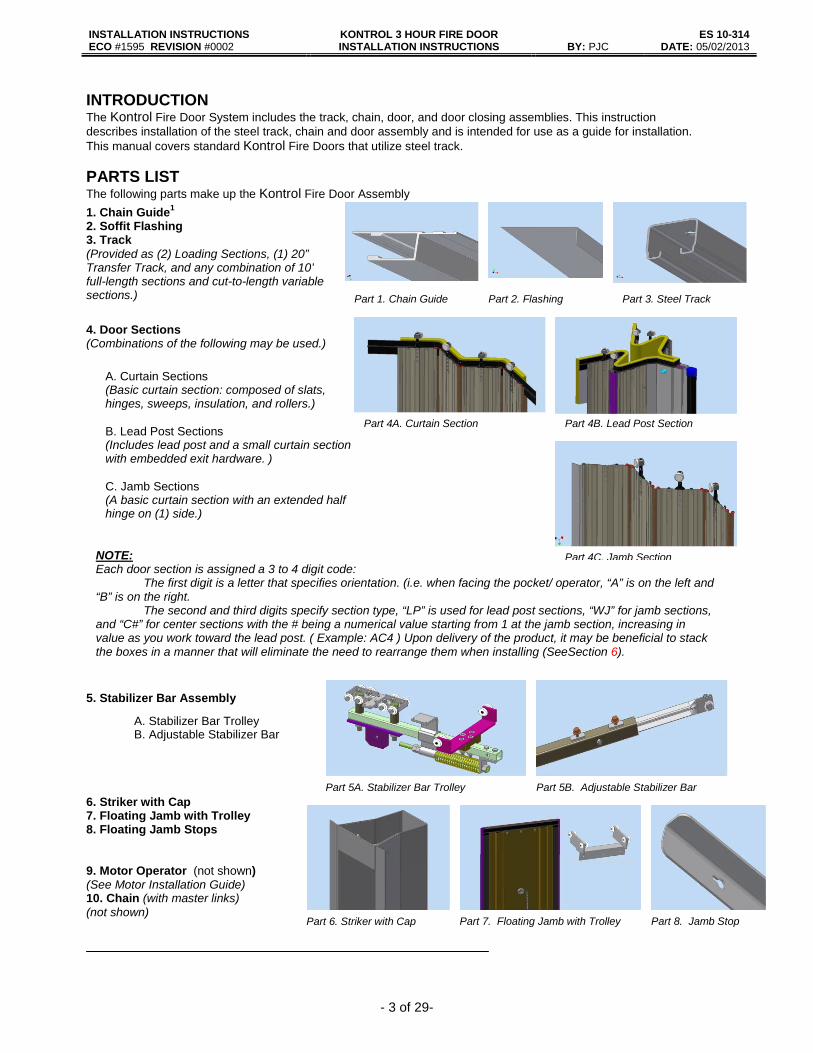
1. Chain Guide1 2. Soffit Flashing 3. Track (Provided as (2) Loading Sections, (1) 20” Transfer Track, and any combination of 10’ full-length sections and cut-to-length variable sections.)
4. Door Sections (Combinations of the following may be used.)
Part 1. Chain Guide Part 2. Flashing Part 3. Steel Track
Part 4B. Lead Post Section Part 4A. Curtain Section
5. Stabilizer Bar Assembly
6. Striker with Cap 7. Floating Jamb with Trolley 8. Floating Jamb Stops 9. Motor Operator (not shown) (See Motor Installation Guide) 10. Chain (with master links) (not shown)
Part 5A. Stabilizer Bar Trolley Part 5B. Adjustable Stabilizer Bar
A. Stabilizer Bar Trolley B. Adjustable Stabilizer Bar
A. Curtain Sections (Basic curtain section: composed of slats, hinges, sweeps, insulation, and rollers.) B. Lead Post Sections (Includes lead post and a small curtain section with embedded exit hardware. ) C. Jamb Sections (A basic curtain section with an extended half hinge on (1) side.)
INTRODUCTION The Kontrol Fire Door System includes the track, chain, door, and door closing assemblies. This instruction describes installation of the steel track, chain and door assembly and is intended for use as a guide for installation. This manual covers standard Kontrol Fire Doors that utilize steel track.
PARTS LIST The following parts make up the Kontrol Fire Door Assembly
Part 6. Striker with Cap Part 7. Floating Jamb with Trolley Part 8. Jamb Stop
Part 4C. Jamb Section
INSTALLATION INSTRUCTIONS KONTROL 3 HOUR FIRE DOOR INSTALLATION INSTRUCTIONS
ES 10-314 ECO #1595 REVISION #0002 BY: PJC DATE: 05/02/2013
- 4 of 29-
TOOLS REQUIRED
The following tools may be required to install the Fire Door Assembly: (Additional tools will be required for the installation of the Fire Door Operator. Electric and/or Battery Drivers Driver Tips (#2 square head & #2 Phillips) Drill Drill Bits (#29, #28, #25, 1/4” at minimum) Utility Knife Scissors Rivet Gun Long Nose Pliers Chalk Line Chop Saw File Saw Horses Ladders / Scaffolding Rubber Mallet
String Level Measuring Tape 10-24 Tap (Steel Header) Chain Breaker for # 40 Chain #2 Flathead Screwdriver #2 Phillips Screwdriver Wire Cutters / Strippers / Crimpers Wrenches (1/2”, 7/16”, 9/16”, & 3/4”) Sockets (7/16”, 1/2” & 9/16) Deep Socket ( ¾”) Ratchet and 15” extension
Optional Tools: (The following tools are not required but have been found to be helpful during installation) − Hand Truck − Rubber Tipped Clamps (see Step 5 of Section 3. Chain Guide/Drive Chain for details.) − Rag / Mild Household Cleaning Solution (To wipe down track, chain guide, walls, header, etc. after
installation is complete) − Voltmeter/Multimeter HARDWARE LIST
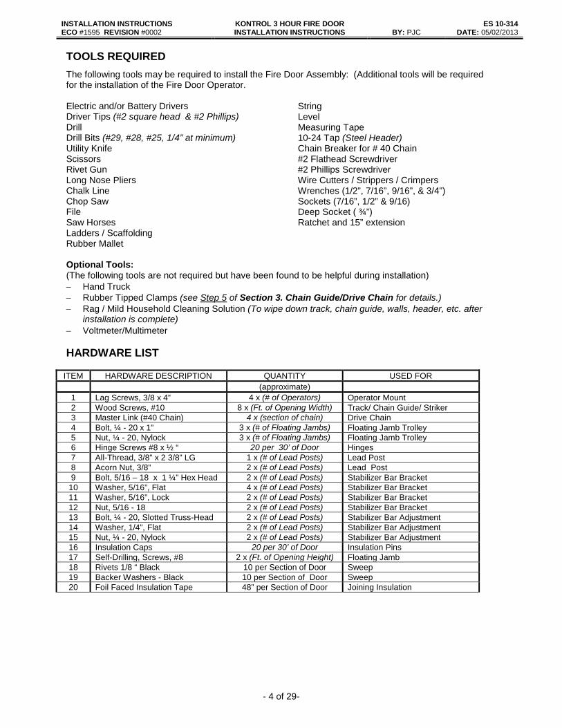
ITEM HARDWARE DESCRIPTION QUANTITY USED FOR (approximate)
1 Lag Screws, 3/8 x 4” 4 x (# of Operators) Operator Mount 2 Wood Screws, #10 8 x (Ft. of Opening Width) Track/ Chain Guide/ Striker 3 Master Link (#40 Chain) 4 x (section of chain) Drive Chain 4 Bolt, ¼ - 20 x 1” 3 x (# of Floating Jambs) Floating Jamb Trolley 5 Nut, ¼ - 20, Nylock 3 x (# of Floating Jambs) Floating Jamb Trolley 6 Hinge Screws #8 x ½ “ 20 per 30’ of Door Hinges 7 All-Thread, 3/8” x 2 3/8” LG 1 x (# of Lead Posts) Lead Post 8 Acorn Nut, 3/8” 2 x (# of Lead Posts) Lead Post 9 Bolt, 5/16 – 18 x 1 ¼” Hex Head 2 x (# of Lead Posts) Stabilizer Bar Bracket
10 Washer, 5/16”, Flat 4 x (# of Lead Posts) Stabilizer Bar Bracket 11 Washer, 5/16”, Lock 2 x (# of Lead Posts) Stabilizer Bar Bracket 12 Nut, 5/16 - 18 2 x (# of Lead Posts) Stabilizer Bar Bracket 13 Bolt, ¼ - 20, Slotted Truss-Head 2 x (# of Lead Posts) Stabilizer Bar Adjustment 14 Washer, 1/4”, Flat 2 x (# of Lead Posts) Stabilizer Bar Adjustment 15 Nut, ¼ - 20, Nylock 2 x (# of Lead Posts) Stabilizer Bar Adjustment 16 Insulation Caps 20 per 30’ of Door Insulation Pins 17 Self-Drilling, Screws, #8 2 x (Ft. of Opening Height) Floating Jamb 18 Rivets 1/8 “ Black 10 per Section of Door Sweep 19 Backer Washers - Black 10 per Section of Door Sweep 20 Foil Faced Insulation Tape 48” per Section of Door Joining Insulation

INSTALLATION INSTRUCTIONS KONTROL 3 HOUR FIRE DOOR INSTALLATION INSTRUCTIONS
ES 10-314 ECO #1595 REVISION #0002 BY: PJC DATE: 05/02/2013
- 5 of 29-
BEFORE INSTALLATION
If wall or header construction of the opening does not conform to the requirements set forth on
the Cookson drawings, the UL label or certificate for the door will not be valid. NOTE: Batteries must be installed and control connected to AC power for minimum of 2 to 3 Hrs prior to testing the DC only operation of the door.
I. Wall Opening Inspection
The wall construction in the area of the opening should be inspected to verify that it conforms to the conditions shown on the Cookson shop drawings provided for the specific door/wall combination. This specifically includes the construction of the pocket(s), header, and striker channel.
The opening must be measured and compared with the shop drawings and production “cut sheet”. Focused inspection is required to verify that the opening is properly prepared to accept the door. The “cut sheet” is a production document prepared at the factory that indicates the lengths to which the components were cut for each opening.
II. Product Inspection
Each box should be inspected for damage. Any freight damage should have been noted and documented on the delivery receipt with freight carrier at time of receipt. Damaged boxes must be documented (photos are required) and the factory should be contacted for further information on investigating any freight claims against the freight carrier company. Note: Door section boxes are marked according to specific door locations, door numbers and hanging position (See note on page 3). Do not unpack the boxes until it is time to install the door. Refer to Figure 6.3 to determine the order in which the door sections must be loaded. Stacking the boxes in a convenient order when received will greatly reduce time and effort during the loading process. III. Locate and Mark the Centerline of the Header The centerline of the header should be marked with a chalk line. The header width must be 18” minimum and span the entire distance from the back wall of the pocket -to- either the striker wall . The centerline mark must allow 9” minimum clearance on either side of the line. Failure to meet this requirement means that the width available for the door when stacked will not be sufficient. Standard straight track header shown in Figure III.1 and Figure III.2.
Figure III.1. Marking the Centerline Figure III.2. Finished Centerline
INSTALLATION INSTRUCTIONS KONTROL 3 HOUR FIRE DOOR INSTALLATION INSTRUCTIONS
ES 10-314 ECO #1595 REVISION #0002 BY: PJC DATE: 05/02/2013
- 6 of 29-
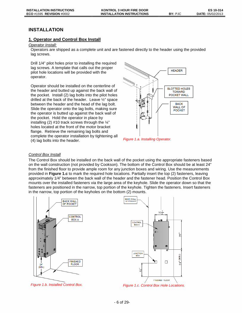
INSTALLATION 1. Operator and Control Box Install Operator Install: Operators are shipped as a complete unit and are fastened directly to the header using the provided lag screws. Drill 1/4” pilot holes prior to installing the required lag screws. A template that calls out the proper pilot hole locations will be provided with the operator. Operator should be installed on the centerline of the header and butted up against the back wall of the pocket. Install (2) lag bolts into the pilot holes drilled at the back of the header. Leave ½” space between the header and the head of the lag bolt. Slide the operator onto the lag bolts, making sure the operator is butted up against the back wall of the pocket. Hold the operator in place by installing (2) #10 track screws through the ¼” holes located at the front of the motor bracket flange. Retrieve the remaining lag bolts and complete the operator installation by tightening all (4) lag bolts into the header.
Figure 1.a. Installing Operator.
Control Box Install The Control Box should be installed on the back wall of the pocket using the appropriate fasteners based on the wall construction (not provided by Cookson). The bottom of the Control Box should be at least 24” from the finished floor to provide ample room for any junction boxes and wiring. Use the measurements provided in Figure 1.c to mark the required hole locations. Partially insert the top (2) fasteners, leaving approximately 1/4” between the back wall of the header and the fastener head. Position the Control Box mounts over the installed fasteners via the large area of the keyhole. Slide the operator down so that the fasteners are positioned in the narrow, top portion of the keyhole. Tighten the fasteners. Insert fasteners in the narrow, top portion of the keyholes on the bottom (2) mounts.
Figure 1.b. Installed Control Box.
Figure 1.c. Control Box Hole Locations.
INSTALLATION INSTRUCTIONS KONTROL 3 HOUR FIRE DOOR INSTALLATION INSTRUCTIONS
ES 10-314 ECO #1595 REVISION #0002 BY: PJC DATE: 05/02/2013
- 7 of 29-
2. Striker Install
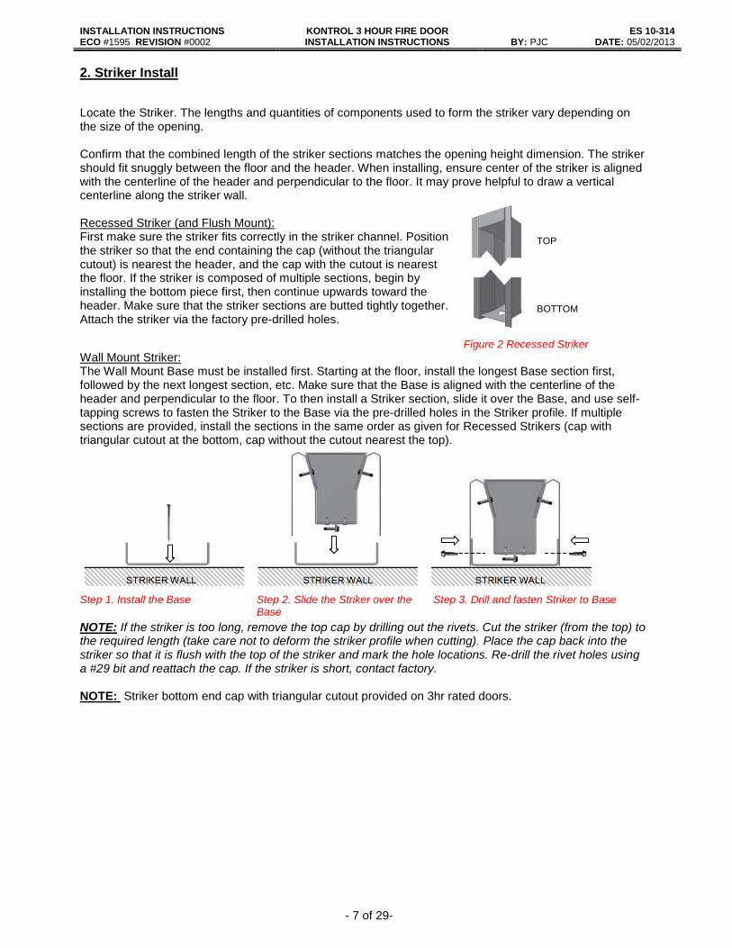
Locate the Striker. The lengths and quantities of components used to form the striker vary depending on the size of the opening. Confirm that the combined length of the striker sections matches the opening height dimension. The striker should fit snuggly between the floor and the header. When installing, ensure center of the striker is aligned with the centerline of the header and perpendicular to the floor. It may prove helpful to draw a vertical centerline along the striker wall. Recessed Striker (and Flush Mount): First make sure the striker fits correctly in the striker channel. Position the striker so that the end containing the cap (without the triangular cutout) is nearest the header, and the cap with the cutout is nearest the floor. If the striker is composed of multiple sections, begin by installing the bottom piece first, then continue upwards toward the header. Make sure that the striker sections are butted tightly together. Attach the striker via the factory pre-drilled holes.
TOP
BOTTOM
Figure 2 Recessed Striker Wall Mount Striker: The Wall Mount Base must be installed first. Starting at the floor, install the longest Base section first, followed by the next longest section, etc. Make sure that the Base is aligned with the centerline of the header and perpendicular to the floor. To then install a Striker section, slide it over the Base, and use self-tapping screws to fasten the Striker to the Base via the pre-drilled holes in the Striker profile. If multiple sections are provided, install the sections in the same order as given for Recessed Strikers (cap with triangular cutout at the bottom, cap without the cutout nearest the top).
Step 1. Install the Base Step 2. Slide the Striker over the
Base Step 3. Drill and fasten Striker to Base
NOTE: If the striker is too long, remove the top cap by drilling out the rivets. Cut the striker (from the top) to the required length (take care not to deform the striker profile when cutting). Place the cap back into the striker so that it is flush with the top of the striker and mark the hole locations. Re-drill the rivet holes using a #29 bit and reattach the cap. If the striker is short, contact factory. NOTE: Striker bottom end cap with triangular cutout provided on 3hr rated doors.

INSTALLATION INSTRUCTIONS KONTROL 3 HOUR FIRE DOOR INSTALLATION INSTRUCTIONS
ES 10-314 ECO #1595 REVISION #0002 BY: PJC DATE: 05/02/2013
- 8 of 29-
3. Chain Guide / Drive Chain Install Locate and unpack the chain guide. The chain guide is provided in some combination of the following types: Loading Sections, Full 10’ Sections (quantities vary), and Variable Sections (length and quantity vary). Loading Sections and Variable Sections will be labeled with a three-letter code. The first letter of each code indicates which side the section should be installed. (When facing the pocket, the left-hand side is the “A” side.) The last (2) letters indicate whether it is a load section (LS) or variable section (VS). Variable Sections may need to be cut to size in the field. A “cut” end should never be used in a joint with another section of chain guide. (I.e. The Variable Section’s “cut” end should face the back wall of the pocket). The ends of the Full 10’ Sections are labeled with a 2-3 digit code. The first digit indicates the side on which they should be installed. The following digits are the joint number. (A1 butts against the “A”-side load section, A2 butts to A2, A3 to A3, etc.) This is important because the predrilled holes of the track and chain guide may not align if they are not installed in the correct positions. It may be helpful to simulate the layout of chain guide on the floor prior to installation. See Figure 3a.
LOADING SECTION FULL 10’ SECTIONS
OPE
RA
TOR
STRIKER WALL
BLS
VARIABLE SECTION
ALS
BVS
AVS
B1
A1
B1
A1
B2
A2
B2
A2
B3
A3
B3
A3
B1
A1
B2
A2
B2
A2
B3
A3
B3
A3ALS
BLS
AVS
BVS
TRACK CHAIN GUIDEPLATE
(3 HR ONLY)
Figure 3a. Chain Guide and Track Arrangement (TOP VIEW)
NOTE: When possible, field cuts should be positioned so that they fall within pocket area for aesthetic purposes. Chain guide sections are best cut to length using a chop saw and then deburred as needed.
Step 1. Fixed Loading Section and Sprocket Assembly Locate the (2) Loading Sections (labeled ALS and BLS) of Chain Guide and the End Sprocket Assembly. The stabilizer bar trolley will later be loaded at this point by removing one side of the Loading Section, but the full Loading Section must first be completely installed to ensure the spacing and length of the entire chain guide assembly. NOTE: The ALS section of the chain guide loading section will be removed later in the install. It is recommended that the minimum number of fasteners (2) needed to hold the chain guide in place be installed at this stage. Locate the Chain Guide Loading Section labeled ALS. Insert the End Sprocket Assembly into the end of chain guide opposite the notch as shown in Figure 3.1. Position the assembly so that the back of the sprocket assembly is butted up to the striker cap. Align the inner edge of the chain guide with the centerline of the header while keeping the sprocket assembly securely in place. Attach the chain guide using the provided hardware (4” X #10 screws if mounting to a wood header or #10-24 Flathead screws ¾” long if mounting to steel header). Pilot holes should be drilled using a #28 (0.141) diameter drill bit.
Figure 3.1. Chain Guide Loading Section and Sprocket Assembly
INSTALLATION INSTRUCTIONS KONTROL 3 HOUR FIRE DOOR INSTALLATION INSTRUCTIONS
ES 10-314 ECO #1595 REVISION #0002 BY: PJC DATE: 05/02/2013
- 9 of 29-
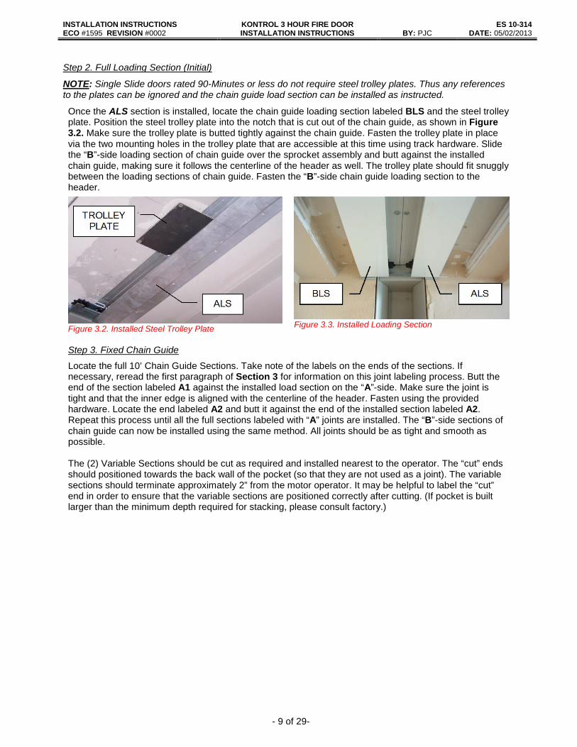
Step 2. Full Loading Section (Initial)
NOTE: Single Slide doors rated 90-Minutes or less do not require steel trolley plates. Thus any references to the plates can be ignored and the chain guide load section can be installed as instructed.
Once the ALS section is installed, locate the chain guide loading section labeled BLS and the steel trolley plate. Position the steel trolley plate into the notch that is cut out of the chain guide, as shown in Figure 3.2. Make sure the trolley plate is butted tightly against the chain guide. Fasten the trolley plate in place via the two mounting holes in the trolley plate that are accessible at this time using track hardware. Slide the “B”-side loading section of chain guide over the sprocket assembly and butt against the installed chain guide, making sure it follows the centerline of the header as well. The trolley plate should fit snuggly between the loading sections of chain guide. Fasten the “B”-side chain guide loading section to the header.
Figure 3.2. Installed Steel Trolley Plate Figure 3.3. Installed Loading Section
Step 3. Fixed Chain Guide
Locate the full 10’ Chain Guide Sections. Take note of the labels on the ends of the sections. If necessary, reread the first paragraph of Section 3 for information on this joint labeling process. Butt the end of the section labeled A1 against the installed load section on the “A”-side. Make sure the joint is tight and that the inner edge is aligned with the centerline of the header. Fasten using the provided hardware. Locate the end labeled A2 and butt it against the end of the installed section labeled A2. Repeat this process until all the full sections labeled with “A” joints are installed. The “B”-side sections of chain guide can now be installed using the same method. All joints should be as tight and smooth as possible. The (2) Variable Sections should be cut as required and installed nearest to the operator. The “cut” ends should positioned towards the back wall of the pocket (so that they are not used as a joint). The variable sections should terminate approximately 2” from the motor operator. It may be helpful to label the “cut” end in order to ensure that the variable sections are positioned correctly after cutting. (If pocket is built larger than the minimum depth required for stacking, please consult factory.)
INSTALLATION INSTRUCTIONS KONTROL 3 HOUR FIRE DOOR INSTALLATION INSTRUCTIONS
ES 10-314 ECO #1595 REVISION #0002 BY: PJC DATE: 05/02/2013
- 10 of 29-
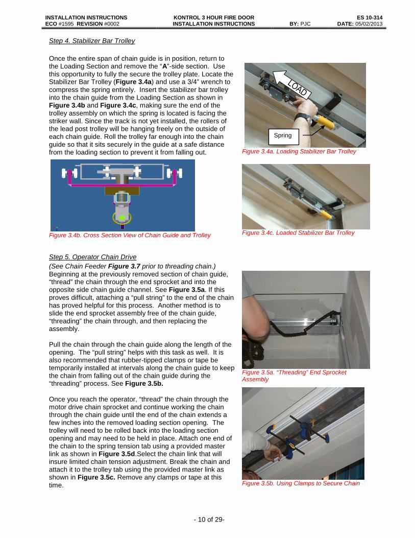
Step 4. Stabilizer Bar Trolley Once the entire span of chain guide is in position, return to the Loading Section and remove the “A”-side section. Use this opportunity to fully the secure the trolley plate. Locate the Stabilizer Bar Trolley (Figure 3.4a) and use a 3/4” wrench to compress the spring entirely. Insert the stabilizer bar trolley into the chain guide from the Loading Section as shown in Figure 3.4b and Figure 3.4c, making sure the end of the trolley assembly on which the spring is located is facing the striker wall. Since the track is not yet installed, the rollers of the lead post trolley will be hanging freely on the outside of each chain guide. Roll the trolley far enough into the chain guide so that it sits securely in the guide at a safe distance from the loading section to prevent it from falling out.
Figure 3.4a. Loading Stabilizer Bar Trolley
Figure 3.4b. Cross Section View of Chain Guide and Trolley
Figure 3.4c. Loaded Stabilizer Bar Trolley
Step 5. Operator Chain Drive
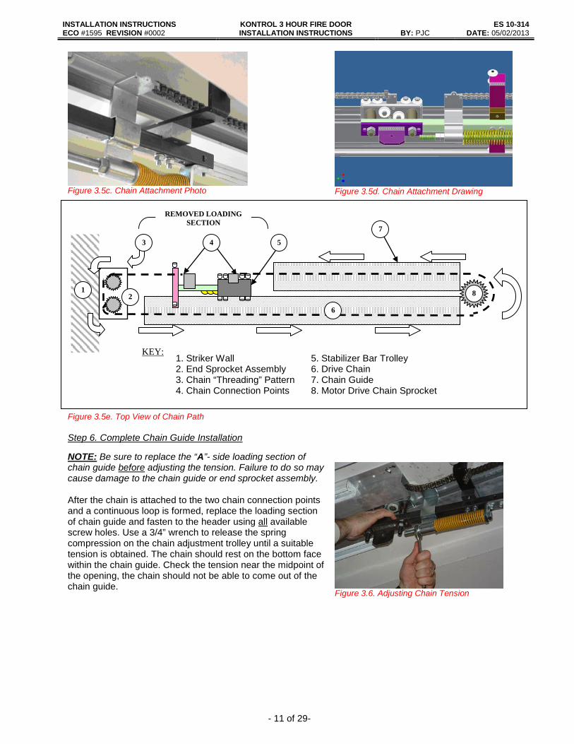
(See Chain Feeder Figure 3.7 prior to threading chain.) Beginning at the previously removed section of chain guide, “thread” the chain through the end sprocket and into the opposite side chain guide channel. See Figure 3.5a. If this proves difficult, attaching a “pull string” to the end of the chain has proved helpful for this process. Another method is to slide the end sprocket assembly free of the chain guide, “threading” the chain through, and then replacing the assembly. Pull the chain through the chain guide along the length of the opening. The “pull string” helps with this task as well. It is also recommended that rubber-tipped clamps or tape be temporarily installed at intervals along the chain guide to keep the chain from falling out of the chain guide during the “threading” process. See Figure 3.5b. Once you reach the operator, “thread” the chain through the motor drive chain sprocket and continue working the chain through the chain guide until the end of the chain extends a few inches into the removed loading section opening. The trolley will need to be rolled back into the loading section opening and may need to be held in place. Attach one end of the chain to the spring tension tab using a provided master link as shown in Figure 3.5d.Select the chain link that will insure limited chain tension adjustment. Break the chain and attach it to the trolley tab using the provided master link as shown in Figure 3.5c. Remove any clamps or tape at this time.
Figure 3.5a. “Threading” End Sprocket Assembly
Figure 3.5b. Using Clamps to Secure Chain
Spring
INSTALLATION INSTRUCTIONS KONTROL 3 HOUR FIRE DOOR INSTALLATION INSTRUCTIONS
ES 10-314 ECO #1595 REVISION #0002 BY: PJC DATE: 05/02/2013
- 11 of 29-
Figure 3.5c. Chain Attachment Photo
Figure 3.5d. Chain Attachment Drawing
Figure 3.5e. Top View of Chain Path
Step 6. Complete Chain Guide Installation
NOTE: Be sure to replace the “A”- side loading section of chain guide before adjusting the tension. Failure to do so may cause damage to the chain guide or end sprocket assembly. After the chain is attached to the two chain connection points and a continuous loop is formed, replace the loading section of chain guide and fasten to the header using all available screw holes. Use a 3/4” wrench to release the spring compression on the chain adjustment trolley until a suitable tension is obtained. The chain should rest on the bottom face within the chain guide. Check the tension near the midpoint of the opening, the chain should not be able to come out of the chain guide.
Figure 3.6. Adjusting Chain Tension
8
REMOVED LOADING SECTION
1. Striker Wall 5. Stabilizer Bar Trolley 2. End Sprocket Assembly 6. Drive Chain 3. Chain “Threading” Pattern 7. Chain Guide 4. Chain Connection Points 8. Motor Drive Chain Sprocket
KEY:
1
3 5 7
2
6
4

INSTALLATION INSTRUCTIONS KONTROL 3 HOUR FIRE DOOR INSTALLATION INSTRUCTIONS
ES 10-314 ECO #1595 REVISION #0002 BY: PJC DATE: 05/02/2013
- 12 of 29-
Optional Chain Feeder: To help the chain “threading” process, a chain feeder may be constructed. This is composed of a square piece of plywood with a pin through the center. The size of the plywood square needed will depend on the amount of chain being used, but should not exceed the width of the header. Pre-drill holes approximately 3/16” in. diameter on each corner of the plywood. Driving a nail through the exact center of the board works nicely as a pin, and rounding the tip may prevent injury. Place the open pinhole of the first chain link over the nail and wrap the chain counterclockwise around the nail without overlapping, creating a flat coil on the plywood. Use the track screws to loosely fasten the feeder to the header in the center of the loading section, making sure not to install the screws far enough that the chain coil makes contact with the header.
Figure 3.7. Optional Chain Feeder
The chain feeder should then allow the chain to be smoothly fed into the end sprocket during the “threading” process. Once the coil fully unwinds, remove the chain feeder and hardware from the header. Repeat procedure until all chain is threaded onto chain guide.
4. Track Install Locate and unpack the track. The Load and Variable Sections have been labeled with the same (3) digit code as used in for the chain guide sections. The joints of the Full Sections have been labeled similarly to the chain guide ends. It may be helpful to simulate the layout of track on the floor. See Figure 3a. The door sections will later be loaded by removing both sides of the Load Section, but the full Load Section must first be completely installed to ensure the spacing and length of the entire chain guide assembly. NOTE: When possible, field cuts should be positioned so that they fall within pocket area for aesthetic purposes. Track sections are best cut to length using a chop saw and then deburred as needed.
Step 1. Track Load Section (Initial)
NOTE: Both sides of the track load section will be removed later during the install. It is recommended that only the minimum number of fasteners needed to hold the track in place be installed at this stage. This prevents unnecessary work as well as preserving the integrity of the header. Locate the (2) Load Sections of track. Position (1) of the track load sections so that the edge is butted tightly against the striker wall and the inside edge is tightly butted up against the chain guide as shown in Figure 4.1a. Use the label on the section to determine orientation. Check to see that the holes in the track and chain guide are aligned. Make sure that the joints of the track and chain guide are staggered by approximately 6”, as shown in Figure 4.1b. Use the 4” x #10 screws provided to mount the track to the header. Repeat for remaining Load Section. NOTE: Steel track has directional arrows stamped into the track. To insure proper track alignment at track joints it is imperative that arrow heads face arrow heads and opposite ends face opposite ends.
Figure 4.1a. Positioning Track
Figure 4.1b. Staggered Track and Chain Guide Joints

INSTALLATION INSTRUCTIONS KONTROL 3 HOUR FIRE DOOR INSTALLATION INSTRUCTIONS
ES 10-314 ECO #1595 REVISION #0002 BY: PJC DATE: 05/02/2013
- 13 of 29-
Step 2. Fixed Track:
Steel Track has directional arrows stamped into the track. In order to ensure proper alignment at the joints, it is imperative that the arrows on the two track sections forming a joint are always
pointing in opposing directions. See Figures below.
Locate all full 10’ track sections. Each end of the full 10’ sections will be labeled with a 2-3 digit code. The first digit will signify which side the track should be installed on, “A” or “B”. The last digit(s) indicates the order the sections should be installed in starting from the load section. Butt the end of the section labeled A1 against the installed load section on the “A”-side. Check to see that the holes in the track align with the holes in the chain guide. If not, check that the track and chain guide sections are positioned correctly. Make sure the inner edge of the track is butted tightly against the chain guide and that the joint is tight. Fasten the track to the header with the provided 4” x #10 screws. Follow the same pattern as used for the chain guide joints to install the remaining Full 10’ Sections of track. All joints should be as tight and smooth as possible. Check stamped arrow orientation to insure proper track alignment. The last (2) sections of track to be installed (closest to the motor operator) are called Variable Sections, and are labeled AVS and BVS. These sections must be field cut to the required size. The cut side of each section should face the back wall of the pocket, as to not be used in a joint. The “A” and “B” designations should also be used in positioning the sections. Cut Variable Sections so that they extend past the drive chain sprocket and terminate approximately ½” from the back wall of the pocket.
5. Initial Limit Switch Adjustment
Do not run the trolley near either end of the track before the operator limits are set. This may result
in damage to the trolley, track, striker, etc. Set the “OPEN” and “CLOSE” limits. Refer to Section 3. Limit Switch Adjustment in the installation guide provided with the operator. Make sure the trolley runs smoothly over each joint making adjustments where misalignments are noticed.
INSTALLATION INSTRUCTIONS KONTROL 3 HOUR FIRE DOOR INSTALLATION INSTRUCTIONS
ES 10-314 ECO #1595 REVISION #0002 BY: PJC DATE: 05/02/2013
- 14 of 29-
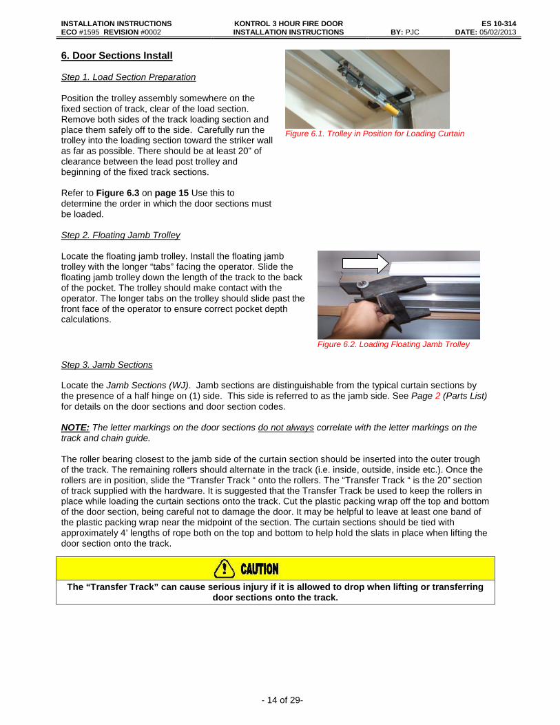
6. Door Sections Install Step 1. Load Section Preparation Position the trolley assembly somewhere on the fixed section of track, clear of the load section. Remove both sides of the track loading section and place them safely off to the side. Carefully run the trolley into the loading section toward the striker wall as far as possible. There should be at least 20” of clearance between the lead post trolley and beginning of the fixed track sections. Refer to Figure 6.3 on page 15 Use this to determine the order in which the door sections must be loaded.
Figure 6.1. Trolley in Position for Loading Curtain
Step 2. Floating Jamb Trolley Locate the floating jamb trolley. Install the floating jamb trolley with the longer “tabs” facing the operator. Slide the floating jamb trolley down the length of the track to the back of the pocket. The trolley should make contact with the operator. The longer tabs on the trolley should slide past the front face of the operator to ensure correct pocket depth calculations.
Figure 6.2. Loading Floating Jamb Trolley
Step 3. Jamb Sections
Locate the Jamb Sections (WJ). Jamb sections are distinguishable from the typical curtain sections by the presence of a half hinge on (1) side. This side is referred to as the jamb side. See Page 2 (Parts List) for details on the door sections and door section codes.
NOTE: The letter markings on the door sections do not always correlate with the letter markings on the track and chain guide. The roller bearing closest to the jamb side of the curtain section should be inserted into the outer trough of the track. The remaining rollers should alternate in the track (i.e. inside, outside, inside etc.). Once the rollers are in position, slide the “Transfer Track “ onto the rollers. The “Transfer Track “ is the 20” section of track supplied with the hardware. It is suggested that the Transfer Track be used to keep the rollers in place while loading the curtain sections onto the track. Cut the plastic packing wrap off the top and bottom of the door section, being careful not to damage the door. It may be helpful to leave at least one band of the plastic packing wrap near the midpoint of the section. The curtain sections should be tied with approximately 4’ lengths of rope both on the top and bottom to help hold the slats in place when lifting the door section onto the track.
The “Transfer Track” can cause serious injury if it is allowed to drop when lifting or transferring
door sections onto the track.

INSTALLATION INSTRUCTIONS KONTROL 3 HOUR FIRE DOOR INSTALLATION INSTRUCTIONS
ES 10-314 ECO #1595 REVISION #0002 BY: PJC DATE: 05/02/2013
- 15 of 29-
Position the jamb section under the correlating track loading section. The side with insulation is the inside and should be facing the chain guide. The half hinge on the jamb side of the section should be facing the pocket and in position to be loaded into the track first.
Slats and hinges are susceptible to bending and twisting when being lifted, especially on taller
doors. Always orient the sections that the hinges are on the top and bottom when lifting. It may be beneficial, and perhaps mandatory on doors that are 10’ or taller, to have at least (3) individuals lifting the door sections, one on each end doing the bulk of the lifting and one in the center to
prevent bending and twisting. Lift the jamb section until the “Transfer Track” is the same height as the fixed track section. A hand truck proves useful for this process. It can be used to “walk” the bottom of the section into place, as well as lifting the slats to the necessary height for loading. Butt the “Transfer Track” so it lines up with the fixed track, creating a smooth joint. Carefully slide the jamb section out of the “Transfer Track” and into the fixed track. Push the jamb section safely away from the opening in the loading section. Check to see if all of the rollers are correctly positioned in the track. Repeat this process for the jamb section on the opposite side.
Figure 6.3. Curtain Section Installation Order (Designated by Arrows)
Step 4. Curtain Sections Locate the Curtain Sections (C#). Refer to the assembly drawing provided to determine the proper placement of the sections. Once again, the side with the insulation and/or wire ties is the inside. The curtain sections with wire ties must all be installed on the same side. Before each section is installed, make sure that the rollers are positioned using the same alternating pattern identified in STEP 3 above.

INSTALLATION INSTRUCTIONS KONTROL 3 HOUR FIRE DOOR INSTALLATION INSTRUCTIONS
ES 10-314 ECO #1595 REVISION #0002 BY: PJC DATE: 05/02/2013
- 16 of 29-
Verify that there is only (1) hinge being used to join each set of door sections. If the (2) end slats that are to be joined together contain hinges, verify that the door section is indeed in the correct position. If so, remove the hinge from the door section that is not yet installed by carefully sliding it out from the top of the curtain. Place it safely off to the side as it may be needed on a different door section. If no hinges are found at a joining section, carefully slide a hinge from the top of the uninstalled door section. Make sure there are screws installed in the top of each bead. If not, install the screws before loading using the extra screws provided by Cookson. Once the hinges are correctly in place, install the remaining curtain sections using the same method as described above for the jamb sections.
Figure 6.4. Door Sections: Lead Post Section (bottom) and Wiring Side Curtain Section (top)
Step 5. Lead Post Section Make sure that all installed door sections are positioned safely away from loading section. Locate the Lead Post Section (LP) of curtain. Move the chain adjustment trolley back so that there is approximately 4” of space between the front roller of the trolley and the beginning of the first full track section. Locate the all-thread and (2) acorn nuts provided by Cookson. Position the Lead Post under the Load Section so that the vertical square tubing inside the lead post is butted up against the horizontal square tubing of the stabilizer bar trolley. It may be helpful to place the lead post section on a hand truck to alleviate the task of moving and lifting the lead post into position. Align the pre-drilled holes located near the mouth of the lead post with the pre-drilled holes in the square tubing of the stabilizer bar trolley. Fasten the lead post to the stabilizer bar trolley using the all-thread and acorn nuts. See Figure 6.5. The all-thread is not designed to support the lead post itself for any
Figure 6.5. Attaching Lead Post to Chain Adjustment Trolley
extended period of time, so the remainder of this step should be completed immediately. The rollers attached to the slats on the lead post section must be inserted into the installed track before the trolley rollers. Confirm that the hinge pattern and roller positioning of the slats attached to the lead post are consistent with the other door sections. Lift the lead post section as needed and slide the rollers into the track. This may require some adjustment since both sides of rollers must be installed simultaneously. It may be necessary to slide the trolley toward the installed track sections in order to load the rollers. Once all (4) of the slat rollers are in place within the track, slide the lead post section into the installed track and clear from the load section.
Step 6. Complete Track
Once all door sections are installed, replace the (2) loading sections of track utilizing all screw holes.
INSTALLATION INSTRUCTIONS KONTROL 3 HOUR FIRE DOOR INSTALLATION INSTRUCTIONS
ES 10-314 ECO #1595 REVISION #0002 BY: PJC DATE: 05/02/2013
- 17 of 29-
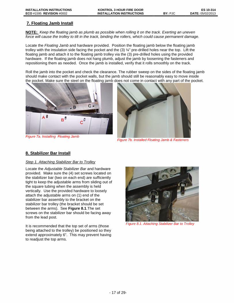
7. Floating Jamb Install NOTE: Keep the floating jamb as plumb as possible when rolling it on the track. Exerting an uneven force will cause the trolley to tilt in the track, binding the rollers, which could cause permanent damage. Locate the Floating Jamb and hardware provided. Position the floating jamb below the floating jamb trolley with the insulation side facing the pocket and the (3) ¼” pre-drilled holes near the top. Lift the floating jamb and attach it to the floating jamb trolley via the (3) pre-drilled holes using the provided hardware. If the floating jamb does not hang plumb, adjust the jamb by loosening the fasteners and repositioning them as needed. Once the jamb is installed, verify that it rolls smoothly on the track.
Roll the jamb into the pocket and check the clearance. The rubber sweep on the sides of the floating jamb should make contact with the pocket walls, but the jamb should still be reasonably easy to move inside the pocket. Make sure the steel on the floating jamb does not come in contact with any part of the pocket.
Figure 7a. Installing Floating Jamb Figure 7b. Installed Floating Jamb & Fasteners
8. Stabilizer Bar Install
Step 1. Attaching Stabilizer Bar to Trolley
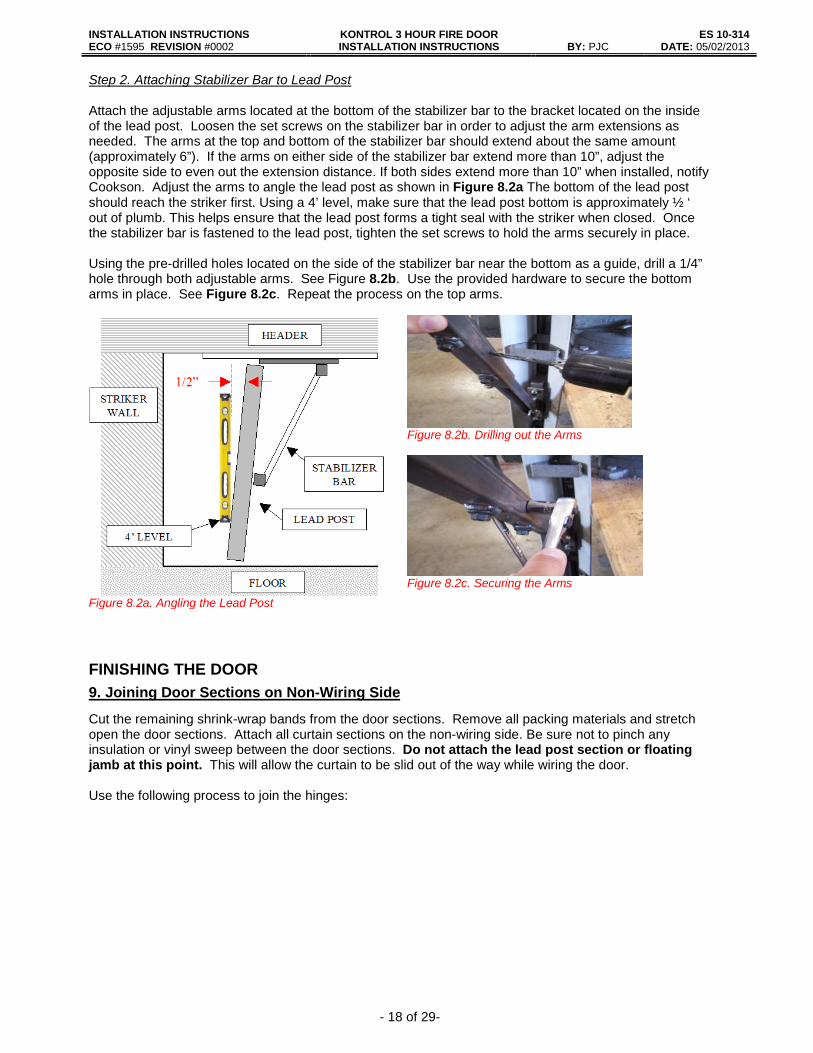
Locate the Adjustable Stabilizer Bar and hardware provided. Make sure the (4) set screws located on the stabilizer bar (two on each end) are sufficiently tight to keep the adjustable arms from sliding out of the square tubing when the assembly is held vertically. Use the provided hardware to loosely attach the adjustable arms on (1) end of the stabilizer bar assembly to the bracket on the stabilizer bar trolley (the bracket should be set between the arms). See Figure 8.1.The set screws on the stabilizer bar should be facing away from the lead post. It is recommended that the top set of arms (those being attached to the trolley) be positioned so they extend approximately 6”. This may prevent having to readjust the top arms.
Figure 8.1. Attaching Stabilizer Bar to Trolley
INSTALLATION INSTRUCTIONS KONTROL 3 HOUR FIRE DOOR INSTALLATION INSTRUCTIONS
ES 10-314 ECO #1595 REVISION #0002 BY: PJC DATE: 05/02/2013
- 18 of 29-
Step 2. Attaching Stabilizer Bar to Lead Post Attach the adjustable arms located at the bottom of the stabilizer bar to the bracket located on the inside of the lead post. Loosen the set screws on the stabilizer bar in order to adjust the arm extensions as needed. The arms at the top and bottom of the stabilizer bar should extend about the same amount (approximately 6”). If the arms on either side of the stabilizer bar extend more than 10”, adjust the opposite side to even out the extension distance. If both sides extend more than 10” when installed, notify Cookson. Adjust the arms to angle the lead post as shown in Figure 8.2a The bottom of the lead post should reach the striker first. Using a 4’ level, make sure that the lead post bottom is approximately ½ ‘ out of plumb. This helps ensure that the lead post forms a tight seal with the striker when closed. Once the stabilizer bar is fastened to the lead post, tighten the set screws to hold the arms securely in place. Using the pre-drilled holes located on the side of the stabilizer bar near the bottom as a guide, drill a 1/4” hole through both adjustable arms. See Figure 8.2b. Use the provided hardware to secure the bottom arms in place. See Figure 8.2c. Repeat the process on the top arms.
Figure 8.2a. Angling the Lead Post
Figure 8.2b. Drilling out the Arms
Figure 8.2c. Securing the Arms
FINISHING THE DOOR 9. Joining Door Sections on Non-Wiring Side
Cut the remaining shrink-wrap bands from the door sections. Remove all packing materials and stretch open the door sections. Attach all curtain sections on the non-wiring side. Be sure not to pinch any insulation or vinyl sweep between the door sections. Do not attach the lead post section or floating jamb at this point. This will allow the curtain to be slid out of the way while wiring the door. Use the following process to join the hinges:

INSTALLATION INSTRUCTIONS KONTROL 3 HOUR FIRE DOOR INSTALLATION INSTRUCTIONS
ES 10-314 ECO #1595 REVISION #0002 BY: PJC DATE: 05/02/2013
- 19 of 29-
Stage 1. Starting at the bottom of the door, align the hinge and slats as shown in the picture below. Strike firmly with rubber mallet in direction of arrow to “pop” the hinge into the bead of the slat.
Stage 2. Once the bottom of the hinge is in the bead, fold the slats as shown below. The bead of the hinge should lie on the opening in the slat. Strike firmly on the face of the hinge. Be careful not to dent the hinge or slats. It may help to slightly slide the mallet towards the unconnected side while striking.
Stage 3. Continue working up the hinge until the entire bead is inside the slat. Fold and extend the slats to verify that the hinge is installed properly. Be sure not to pinch any insulation or vinyl sweep between the hinge and slat
10. Joining Insulation and Sweep
Insulation pins are very sharp. Take necessary measures to prevent injury.
Check to see if any insulation pins are missing a cap. If so, push the insulation onto the curtain until the pin penetrates completely through. Gently press an insulation pin cap onto the exposed pin until it snaps. Take care not to push the cap onto the pin so far that the pin penetrates the dome of the cap. At each joining section on the non-wiring side, trim the insulation flaps on both the top and bottom of the curtain so that they meet flush approximately at the center of the hinge. Use the provided insulation tape to secure the (2) flaps together. The insulation along the bottom of the curtain should just barely make contact with the floor. If necessary, trim the insulation so that it is flush with the floor. Sweep - The vinyl at each joining section (top and bottom) of the non-wiring side can now be joined. Fold the excess sweep on each side of the joining section toward the inside of the door, so that the outside face of each flap is now facing each other. Trim the any sweep beyond the existing hole pattern on both sides. Align the hole pattern in each flap and fasten them together using the (2) outer most holes of the pattern. Be sure to use the larger pop rivets and backer washers provided by Cookson.
Figure 10.2. Joining Sweep
INSTALLATION INSTRUCTIONS KONTROL 3 HOUR FIRE DOOR INSTALLATION INSTRUCTIONS
ES 10-314 ECO #1595 REVISION #0002 BY: PJC DATE: 05/02/2013
- 20 of 29-
11. Joining Door Sections on Wiring Side
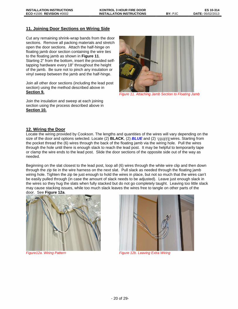
Cut any remaining shrink-wrap bands from the door sections. Remove all packing materials and stretch open the door sections. Attach the half-hinge on floating jamb door section containing the wire ties to the floating jamb as shown in Figure 11. Starting 2” from the bottom, insert the provided self-tapping hardware every 18” throughout the height of the jamb. Be sure not to pinch any insulation or vinyl sweep between the jamb and the half-hinge. Join all other door sections (including the lead post section) using the method described above in Section 9. Join the insulation and sweep at each joining section using the process described above in Section 10.
Figure 11. Attaching Jamb Section to Floating Jamb
12. Wiring the Door Locate the wiring provided by Cookson. The lengths and quantities of the wires will vary depending on the size of the door and options selected. Locate (2) BLACK, (2) BLUE and (2) WWW HHHIIITTTEEE wires. Starting from the pocket thread the (6) wires through the back of the floating jamb via the wiring hole. Pull the wires through the hole until there is enough slack to reach the lead post. It may be helpful to temporarily tape or clamp the wire ends to the lead post. Slide the door sections of the opposite side out of the way as needed. Beginning on the slat closest to the lead post, loop all (6) wires through the white wire clip and then down through the zip tie in the wire harness on the next slat. Pull slack as needed through the floating jamb wiring hole. Tighten the zip tie just enough to hold the wires in place, but not so much that the wires can’t be easily pulled through (in case the amount of slack needs to be adjusted). Leave just enough slack in the wires so they hug the slats when fully stacked but do not go completely taught. Leaving too little slack may cause stacking issues, while too much slack leaves the wires free to tangle on other parts of the door. See Figure 12a.
Figure12a. Wiring Pattern
Figure 12b. Leaving Extra Wiring
INSTALLATION INSTRUCTIONS KONTROL 3 HOUR FIRE DOOR INSTALLATION INSTRUCTIONS
ES 10-314 ECO #1595 REVISION #0002 BY: PJC DATE: 05/02/2013
- 21 of 29-
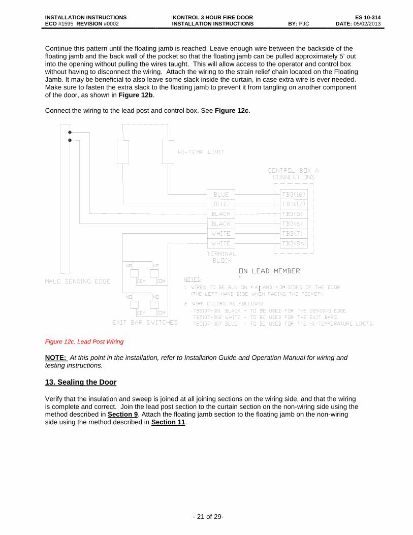
Continue this pattern until the floating jamb is reached. Leave enough wire between the backside of the floating jamb and the back wall of the pocket so that the floating jamb can be pulled approximately 5’ out into the opening without pulling the wires taught. This will allow access to the operator and control box without having to disconnect the wiring. Attach the wiring to the strain relief chain located on the Floating Jamb. It may be beneficial to also leave some slack inside the curtain, in case extra wire is ever needed. Make sure to fasten the extra slack to the floating jamb to prevent it from tangling on another component of the door, as shown in Figure 12b. Connect the wiring to the lead post and control box. See Figure 12c. Figure 12c. Lead Post Wiring NOTE: At this point in the installation, refer to Installation Guide and Operation Manual for wiring and testing instructions. 13. Sealing the Door Verify that the insulation and sweep is joined at all joining sections on the wiring side, and that the wiring is complete and correct. Join the lead post section to the curtain section on the non-wiring side using the method described in Section 9. Attach the floating jamb section to the floating jamb on the non-wiring side using the method described in Section 11.
: “ O
“ “
:
ON LEAD MEMBER “
INSTALLATION INSTRUCTIONS KONTROL 3 HOUR FIRE DOOR INSTALLATION INSTRUCTIONS
ES 10-314 ECO #1595 REVISION #0002 BY: PJC DATE: 05/02/2013
- 22 of 29-
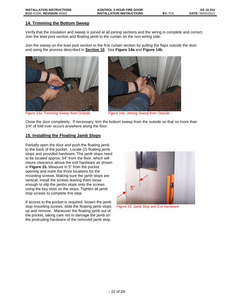
14. Trimming the Bottom Sweep Verify that the insulation and sweep is joined at all joining sections and the wiring is complete and correct. Join the lead post section and floating jamb to the curtain on the non-wiring side. Join the sweep on the lead post section to the first curtain section by pulling the flaps outside the door and using the process described in Section 10. See Figure 14a and Figure 14b.
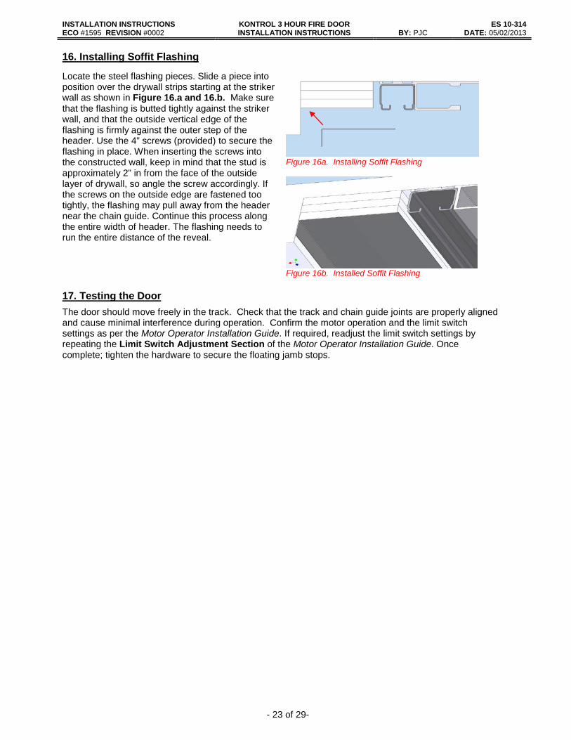
Figure 14a. Trimming Sweep from Outside Figure 14a. Joining Sweep from Outside Close the door completely. If necessary, trim the bottom sweep from the outside so that no more than 1/4” of fold over occurs anywhere along the floor. 15. Installing the Floating Jamb Stops Partially open the door and push the floating jamb to the back of the pocket. Locate (2) floating jamb stops and provided hardware. The jamb stops need to be located approx. 54” from the floor, which will insure clearance above the exit hardware as shown in Figure 15. Measure in 5” from the pocket opening and mark the three locations for the mounting screws. Making sure the jamb stops are vertical, install the screws leaving them loose enough to slip the jambs stops onto the screws using the key slots on the stops. Tighten all jamb stop screws to complete this step. If access to the pocket is required, loosen the jamb stop mounting screws, slide the floating jamb stops up and remove. Maneuver the floating jamb out of the pocket, taking care not to damage the jamb on the protruding hardware of the removed jamb stop.
Figure 15. Jamb Stop and Exit Hardware
INSTALLATION INSTRUCTIONS KONTROL 3 HOUR FIRE DOOR INSTALLATION INSTRUCTIONS
ES 10-314 ECO #1595 REVISION #0002 BY: PJC DATE: 05/02/2013
- 23 of 29-
16. Installing Soffit Flashing
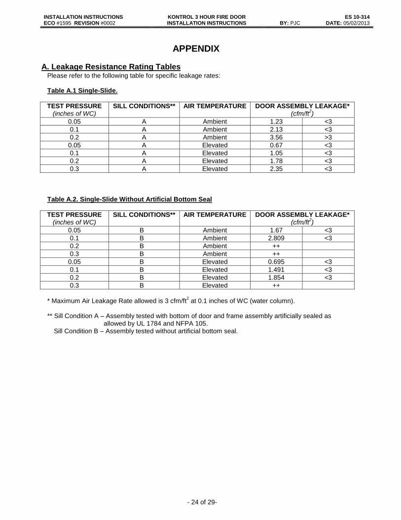
Locate the steel flashing pieces. Slide a piece into position over the drywall strips starting at the striker wall as shown in Figure 16.a and 16.b. Make sure that the flashing is butted tightly against the striker wall, and that the outside vertical edge of the flashing is firmly against the outer step of the header. Use the 4” screws (provided) to secure the flashing in place. When inserting the screws into the constructed wall, keep in mind that the stud is approximately 2” in from the face of the outside layer of drywall, so angle the screw accordingly. If the screws on the outside edge are fastened too tightly, the flashing may pull away from the header near the chain guide. Continue this process along the entire width of header. The flashing needs to run the entire distance of the reveal.
Figure 16a. Installing Soffit Flashing
Figure 16b. Installed Soffit Flashing
17. Testing the Door The door should move freely in the track. Check that the track and chain guide joints are properly aligned and cause minimal interference during operation. Confirm the motor operation and the limit switch settings as per the Motor Operator Installation Guide. If required, readjust the limit switch settings by repeating the Limit Switch Adjustment Section of the Motor Operator Installation Guide. Once complete; tighten the hardware to secure the floating jamb stops.
INSTALLATION INSTRUCTIONS KONTROL 3 HOUR FIRE DOOR INSTALLATION INSTRUCTIONS
ES 10-314 ECO #1595 REVISION #0002 BY: PJC DATE: 05/02/2013
- 24 of 29-
APPENDIX
A. Leakage Resistance Rating Tables
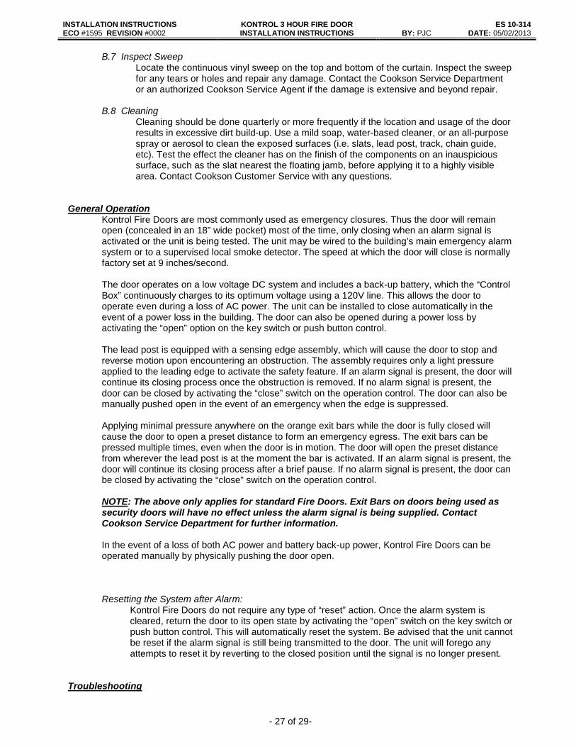
Please refer to the following table for specific leakage rates: Table A.1 Single-Slide. TEST PRESSURE
(inches of WC) SILL CONDITIONS** AIR TEMPERATURE DOOR ASSEMBLY LEAKAGE*
(cfm/ft2) 0.05 A Ambient 1.23 <3 0.1 A Ambient 2.13 <3 0.2 A Ambient 3.56 >3 0.05 A Elevated 0.67 <3 0.1 A Elevated 1.05 <3 0.2 A Elevated 1.78 <3 0.3 A Elevated 2.35 <3
Table A.2. Single-Slide Without Artificial Bottom Seal TEST PRESSURE
(inches of WC) SILL CONDITIONS** AIR TEMPERATURE DOOR ASSEMBLY LEAKAGE*
(cfm/ft2) 0.05 B Ambient 1.67 <3 0.1 B Ambient 2.809 <3 0.2 B Ambient ++ 0.3 B Ambient ++ 0.05 B Elevated 0.695 <3 0.1 B Elevated 1.491 <3 0.2 B Elevated 1.854 <3 0.3 B Elevated ++
* Maximum Air Leakage Rate allowed is 3 cfm/ft2 at 0.1 inches of WC (water column). ** Sill Condition A – Assembly tested with bottom of door and frame assembly artificially sealed as allowed by UL 1784 and NFPA 105. Sill Condition B – Assembly tested without artificial bottom seal.

INSTALLATION INSTRUCTIONS KONTROL 3 HOUR FIRE DOOR INSTALLATION INSTRUCTIONS
ES 10-314 ECO #1595 REVISION #0002 BY: PJC DATE: 05/02/2013
- 25 of 29-
B. General Maintenance and Operation Guide Quick Reference Introduction ............................................................................................................................... 29 Preventive Maintenance ........................................................................................................... 29
Chain .................................................................................................................................. 29 Track/Chain Guide ............................................................................................................. 30 Operation ........................................................................................................................... 30 Sensing Edge ..................................................................................................................... 30 Exit Bars ............................................................................................................................. 30 Rollers / Hanger Pins ......................................................................................................... 30 Sweep ................................................................................................................................ 31 Cleaning ............................................................................................................................. 31
General Operation .................................................................................................................... 31 Troubleshooting .................................................................... ................................................... 32 Introduction
The following information is intended to act as a guideline for the required maintenance and a brief overview of the general operation of a Kontrol Fire Door. Any maintenance or repair issues beyond the scope of this overview require an authorized Cookson Service Technician. Please consult factory with any questions or concerns. The information herein will help acquaint you with the basic operations of Kontrol Fire products, and following the recommended maintenance tips provided will help ensure a long-lasting, safe and secure Fire Door.
Kontrol Fire Doors are integrated into the Fire and Life Safety Equipment of the facility in which
they are installed. To ensure the health and safety of the general public, Kontrol Fire Products should only be installed and serviced by Cookson authorized personnel.
Preventive Maintenance
Standard building codes state that Fire Doors must be cycled semi annually. Cookson recommends a visual inspection and preventive maintenance be performed on Kontrol Fire products quarterly. For a comprehensive and efficient inspection, follow the ensuing steps in order:
Before Operating the Door
B.1 Inspect Chain
a) Locate the drive chain. The drive chain is housed in a specially designed chain guide located between the track sections. Check to see if the chain is properly lubricated. There should always be a light film of lubrication coating the entire chain. Use light oil as required to maintain adequate lubrication.
b) Locate the End Sprocket Assembly. Ensure that the chain is properly threaded along the
sprockets within the assembly. Contact the Cookson Service Department or an authorized Cookson Service Agent for more information before operating the door if the chain is not properly threaded along the sprockets.
c) Straight Track Doors: With the door fully open, choose a location approximately midway
between the trolley and end sprocket assembly. Locate the drive chain. The chain should be resting on the bottom face within the chain guide. Check the tension of both sides of the chain guide; the chain should not be able to come out of the chain guide.

INSTALLATION INSTRUCTIONS KONTROL 3 HOUR FIRE DOOR INSTALLATION INSTRUCTIONS
ES 10-314 ECO #1595 REVISION #0002 BY: PJC DATE: 05/02/2013
- 26 of 29-
B.2 Inspect Track / Chain Guide Inspect the Track and Chain Guide for any damage or anomalies that may impede the operation of the door. Inspect each joint to ensure that it is smooth and tight. Clear the track and chain guide of any debris. Contact the Cookson Service Department or an authorized Cookson Service Agent for more information before operating the door if damage is observed.
Do not operate the door before completing steps 1 and 2. Failing to recognize and rectify
potential problems before operating the door can result in damage to the unit.
B.3 Test Operation Fully close the Kontrol Fire Door by activating the standard push button or optional key switch. Ensure that the door moves smoothly across the entire opening. Once the door is fully closed, check to make sure that the lead post closes securely into the striker/opposing striker. Reopen the door using the push button or key switch, again ensuring a smooth operation. Once the door is fully open, ensure that the door stacks within the pocket(s). Contact the Cookson Service Department or an authorized Cookson Service Agent for more information if any problems are established.
B.4 Test Sensing Edge
Locate the vinyl sensing edge on the front edge of the male lead post. Check to ensure that the edge is firmly attached to the lead post for the entire height of the door. Use the controls to initiate the closing process. While the door is in motion, activate the sensing edge by depressing the leading edge of the vinyl extrusion. The door should stop. Releasing the sensing edge will cause the door to pause for a few seconds before it continues to close. For Bi-Parting doors, repeat these instructions for both steel sensing edges located on the front edge of the female lead post. Contact the Cookson Service Department or an authorized Cookson Service Agent for more information if the sensing edge is loose, not properly aligned, or does not function as stated.
B.5 Test Exit Bars
For standard fire doors, with the door in the fully closed position, locate the orange exit bars. Apply a small amount of pressure to the face in order to depress the exit bar. The door should open partially to a pre-set distance. The distance the door opens varies depending on the option selected. The door is factory set to open to approximately 60”, but can be field programmed to open anywhere from 48” to the entire width of the opening. Check to make sure that the door opens to the specified distance. Contact the Cookson Service Department or an authorized Cookson Service Agent for more information if the exit bars do not function as stated. NOTE: If the fire door is being used as a Security Door, the exit bars on the side selected as the “secure” side will have no effect on the door unless the building’s alarm system is activated. Contact the Cookson Service Department or an authorized Cookson Service Agent for more information concerning Security Door Maintenance.
B.6 Inspect Rollers / Panel Support Hanger Pins
Visually inspect the nylon roller bearings and hanger pin of each slat, as well as the nylon roller bearings of the lead post and floating jamb trolley, for any signs of damage. It is recommended not to use any lubricants on the roller bearings or track unless required. Contact the Cookson Service Department or an authorized Cookson Service Agent for more information concerning the repair and proper lubrication of roller bearings and hanger pins if required.
INSTALLATION INSTRUCTIONS KONTROL 3 HOUR FIRE DOOR INSTALLATION INSTRUCTIONS
ES 10-314 ECO #1595 REVISION #0002 BY: PJC DATE: 05/02/2013
- 27 of 29-
B.7 Inspect Sweep Locate the continuous vinyl sweep on the top and bottom of the curtain. Inspect the sweep for any tears or holes and repair any damage. Contact the Cookson Service Department or an authorized Cookson Service Agent if the damage is extensive and beyond repair.
B.8 Cleaning
Cleaning should be done quarterly or more frequently if the location and usage of the door results in excessive dirt build-up. Use a mild soap, water-based cleaner, or an all-purpose spray or aerosol to clean the exposed surfaces (i.e. slats, lead post, track, chain guide, etc). Test the effect the cleaner has on the finish of the components on an inauspicious surface, such as the slat nearest the floating jamb, before applying it to a highly visible area. Contact Cookson Customer Service with any questions.
General Operation
Kontrol Fire Doors are most commonly used as emergency closures. Thus the door will remain open (concealed in an 18” wide pocket) most of the time, only closing when an alarm signal is activated or the unit is being tested. The unit may be wired to the building’s main emergency alarm system or to a supervised local smoke detector. The speed at which the door will close is normally factory set at 9 inches/second.
The door operates on a low voltage DC system and includes a back-up battery, which the “Control Box” continuously charges to its optimum voltage using a 120V line. This allows the door to operate even during a loss of AC power. The unit can be installed to close automatically in the event of a power loss in the building. The door can also be opened during a power loss by activating the “open” option on the key switch or push button control.
The lead post is equipped with a sensing edge assembly, which will cause the door to stop and reverse motion upon encountering an obstruction. The assembly requires only a light pressure applied to the leading edge to activate the safety feature. If an alarm signal is present, the door will continue its closing process once the obstruction is removed. If no alarm signal is present, the door can be closed by activating the “close” switch on the operation control. The door can also be manually pushed open in the event of an emergency when the edge is suppressed. Applying minimal pressure anywhere on the orange exit bars while the door is fully closed will cause the door to open a preset distance to form an emergency egress. The exit bars can be pressed multiple times, even when the door is in motion. The door will open the preset distance from wherever the lead post is at the moment the bar is activated. If an alarm signal is present, the door will continue its closing process after a brief pause. If no alarm signal is present, the door can be closed by activating the “close” switch on the operation control. NOTE: The above only applies for standard Fire Doors. Exit Bars on doors being used as security doors will have no effect unless the alarm signal is being supplied. Contact Cookson Service Department for further information.
In the event of a loss of both AC power and battery back-up power, Kontrol Fire Doors can be operated manually by physically pushing the door open.
Resetting the System after Alarm: Kontrol Fire Doors do not require any type of “reset” action. Once the alarm system is cleared, return the door to its open state by activating the “open” switch on the key switch or push button control. This will automatically reset the system. Be advised that the unit cannot be reset if the alarm signal is still being transmitted to the door. The unit will forego any attempts to reset it by reverting to the closed position until the signal is no longer present.
Troubleshooting
INSTALLATION INSTRUCTIONS KONTROL 3 HOUR FIRE DOOR INSTALLATION INSTRUCTIONS
ES 10-314 ECO #1595 REVISION #0002 BY: PJC DATE: 05/02/2013
- 28 of 29-
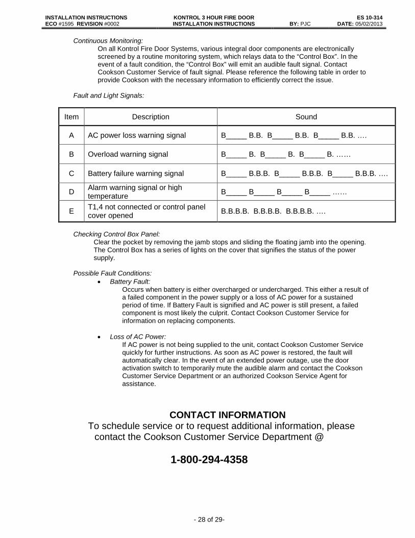
Continuous Monitoring: On all Kontrol Fire Door Systems, various integral door components are electronically screened by a routine monitoring system, which relays data to the “Control Box”. In the event of a fault condition, the “Control Box” will emit an audible fault signal. Contact Cookson Customer Service of fault signal. Please reference the following table in order to provide Cookson with the necessary information to efficiently correct the issue.
Fault and Light Signals:
Item Description Sound
A AC power loss warning signal B_____ B.B. B_____ B.B. B_____ B.B. ….
B Overload warning signal B_____ B. B_____ B. B_____ B. ……
C Battery failure warning signal B_____ B.B.B. B_____ B.B.B. B_____ B.B.B. ….
D Alarm warning signal or high temperature B_____ B_____ B_____ B_____ ……
E T1,4 not connected or control panel cover opened B.B.B.B. B.B.B.B. B.B.B.B. ….
Checking Control Box Panel:
Clear the pocket by removing the jamb stops and sliding the floating jamb into the opening. The Control Box has a series of lights on the cover that signifies the status of the power supply.
Possible Fault Conditions:
• Battery Fault: Occurs when battery is either overcharged or undercharged. This either a result of a failed component in the power supply or a loss of AC power for a sustained period of time. If Battery Fault is signified and AC power is still present, a failed component is most likely the culprit. Contact Cookson Customer Service for information on replacing components.
• Loss of AC Power:
If AC power is not being supplied to the unit, contact Cookson Customer Service quickly for further instructions. As soon as AC power is restored, the fault will automatically clear. In the event of an extended power outage, use the door activation switch to temporarily mute the audible alarm and contact the Cookson Customer Service Department or an authorized Cookson Service Agent for assistance.
CONTACT INFORMATION To schedule service or to request additional information, please
contact the Cookson Customer Service Department @
1-800-294-4358

INSTALLATION INSTRUCTIONS KONTROL 3 HOUR FIRE DOOR INSTALLATION INSTRUCTIONS
ES 10-314 ECO #1595 REVISION #0002 BY: PJC DATE: 05/02/2013
- 29 of 29-
Sash Chain Attachment Instructions
Sash Chain Attachment, to be installed when door billowing issues do not allow the door to retract correctly into the pocket. Note: Your Fire Door has been supplied with enough Sash Chain, Rivets and Backer Washers to accomplish this retrofit. (As Required) This procedure will take two people. First you will need to open the curtain at the floating jamb, starting at the lead post put a mark ( inside the partition ) on both sides every 4 ft., or every 12 slats. Drill a 9/64 dia. hole in the center of the marked slats 10” off the floor. These holes need to be drilled on both sides ( A& B ) or ( C & D ) of the curtain, making sure that the number of slats to the lead post are equal on either side. Starting at the lead post end attach the #35 sash chain ( 19 links ) to both sides riveting in place from the outside using the rivets and backer washers provided. Work your way to the floating jamb attaching the curtain sides together.