Embed Size (px)
Citation preview
ROMANIAN JOURNAL OF INFORMATIONSCIENCE AND TECHNOLOGYVolume 14, Number 1, 2011, 67–80
Transportation Process of Containers
BPMN-Modeling and Transformationinto ACTIF Model
Ismahene HADJ KHALIFA1, Abdelkader EL KAMEL1, Pascal YIM2
1Laboratoire d’Automatique, Genie Informatique et Signal,Ecole Centrale de Lille, BP 48, 59651 Villeneuve d’Ascq Cedex, France
2Groupe 3 SI, Cite numerique,245 Rue Jean Jaures 59650 Villeneuve d’Ascq Cedex, France
E-mail: [email protected],[email protected],
Abstract. In this paper, we propose to model the transportation process
of containers in the Nord-Pas de Calais Region (France). Based on the BPMN
(Business Process Modeling Notation) approach, it allows deriving a comprehen-
sive vision of the process and a friendly-user interface of the logistics chain for
the analysis and the decision making. Furthermore, ACTIF (Aide a la Concep-
tion de systemes de Transports Interoperables en France), a modeling approach
proposed by the French Transportation Ministry, appears to be an interesting
alternative approach since it assures the interoperability between the transport
systems in France. Hence, we propose a model transformation procedure of the
BPMN-model into an ACTIF model.
Key-words: Model Driven Architecture, BPMN model, ACTIF model,
Model Transformation.
1. Introduction
Nowadays, the companies evolve in a more and more complex environment: sev-eral processes to manage, objectives and constraints to optimize, resources to share.
68 I. Hadj Khalifa et al.
Furthermore, in order to stick to the fast-evolution environment, the decision-makerhas to supervise and control the company performances. To achieve this objective, thebusiness process modeling appears as a key-step to understand the current situation,to identify the dysfunctions and to derive the reasons before any decision- making.
This paper proposes a model of the transportation process of containers in Nord-Pas de Calais Region (France) then a model transformation to assure the interoper-ability between the transport systems.
The paper is organized as follows. Section 2 introduces a Model Driven Architec-ture overview. A presentation of the context study is given in Section 3 and of thebusiness process modeling methods state of art in Section 4. In Section 5, we proposea BPMN-model of the transportation process of containers. Finally, in Section 6,we present the technical environment TOPCASED (Toolkit OPen-source for CriticalApplication & SystEms Development) and the transformation language ATL (AtlasTransformation Language), used to transform the BPMN diagram into an ACTIFmodel, besides the different steps to achieve this model transformation.
2. MDA Overview
Model Driven Architecture (MDA) is an approach model-use in software devel-opments. It was launched by the Object Management Group (OMG) in 2001. Itis a framework for software developments that aims to promote the use of modelsand their transformations as a fundamental approach for system design. The threeprimary goals of MDA are portability, interoperability and reusability through archi-tectural separation of concerns [1].
This architecture defines a hierarchy of models from three levels of abstraction:the Computation Independent Model (CIM), the Platform Independent Model (PIM)and the Platform Specific Model (PSM) [1], [2].
• Computation Independent Model
A Computation Independent model (CIM) represents the computational indepen-dent viewpoint. It is a system model that shows the system in the environmentin which it will operate. Hence, it helps in presenting exactly what the system isexpected to do.
• Platform Independent Model
A Platform Independent Model (PIM) is a view of the system from a platform in-dependent viewpoint. It focuses on the system operation, hiding the platform specificdetails, and is independent of the specific technological platform used for implemen-tation. Furthermore, it exhibits platform independence and is suitable for use with anumber of different platforms of similar types.
• Platform Specific Model
A Platform Specific Model (PSM) is a view of the system from the platform specificviewpoint. It combines the specifications in the PIM with the details that specify howthe system uses a particular type of platform. Hence, it is indispensable for systemimplementation.
Transportation Process of Containers BPMN-Modeling 69
The PIM and PSM can be developed by using any specification language. However,UML (Unified Modeling Language) is typically used since it is a standard modelinglanguage. Furthermore, there are important OMG standards in the core of the MDA[1], [3]: MOF (Meta Object Facility) [4], CWM (Common Warehouse Meta-model)[5], UML [1], XMI (XML Metadata Interchange) [6] and OCL (Object ConstraintLanguage) [7].
The key challenge of MDA is in transforming higher-level models into platform-specific models which can be used to generate the implementation level models. Trans-forming a model into another model means that a source model is transformed intoa target model based on given transformation rules [3].
In this paper, we present a case study, in the transport domain, in which wetransformed a BPMN diagram into ACTIF model to guarantee the interoperabilityin the transport domain.
3. Context study
This study is a part of two French projects carried out by the Nord Pas de CalaisRegion. The main objective of these projects is to develop interchanges betweenthe multimodal platforms, to blend the procedures and to introduce the automaticinterfaces.
This study is part of the first stage. Its main purpose is to introduce an organiza-tion which facilitates the harmonization of platform/loader constraints inside Delta 3platform in Dourges, a town in the Nord-Pas de Calais Region, in order to optimizethe local trucking process, i.e. road post-transportation of containers from the fluvialterminal to the warehouses inside the multimodal platform.
To achieve this task, an enterprise process modeling appears as a key-step tounderstand the current situation, to identify the dysfunctions and hence derive thereasons for better decision-making. First, we studied the different steps to transportthe freight from the ship arrival at Dunkerque to the warehouse delivery as well as theinteraction between the actors intervening in the transportation supply chain: LDCT(Lille Dourges Conteneur Terminal), the carrier, the loader, the customs service inDunkerque. . . , the communications process and the information systems used. Thisanalysis allowed us designing the transportation process of containers.
In the next section, we present the enterprise modeling overview. Then, we selectthe suitable approach to model the transportation process.
4. Enterprise modeling overview
In literature, several enterprise modeling methods were advocated, among whichwe quote: GRAI-GIM, UML, ACTIF and BPMN. These methods are briefly presentedin this section then the suitable approach is selected to design the transportationprocess of containers.
70 I. Hadj Khalifa et al.
4.1. GRAI-GIM method
GRAI-GIM (GRAI Integrated Method) is a method based on enterprise model-ing to design or redesign the manufacturing systems. This method focuses mostlyon the decision-making level in a company. Its main goal is to improve the globalenterprise performances [8]. This method can be applied in several domains suchas: manufacturing systems engineering, industrial strategy development, knowledgemanagement. . . The GIM methodology suggests new concepts to describe the decisionmaking systems such as: the GRAI grille and the GRAI network [8]. The GRAI grilleis a table. The columns represent the enterprise functions and the lines represent thedecision-making levels for the different types of decision such as strategic, tacticaland operational decisions with their periods and horizons. The GRAI network is alocal representation of the making-decision center. It defines the activities, the initialstates and the trigger events of the decision-making process [9].
In conclusion, certainly modeling with the GRAI grille or the GRAI network isclear and easy to understand but it does not present a real interest to our study atthis stage.
4.2. UML method
The Unified Modeling Language (UML) is an OMG specification defined by theUML meta-model, a Meta-Object Facility meta-model (MOF). It is a specificationlanguage for object modeling. It is a general-purpose modeling language that includesa graphical notation used to create an abstract model of a system, referred to asa UML model. It is designed to specify, visualize, construct, and document thesoftware-intensive systems. UML is not a method since it does not introduce anyapproach [10]. UML is not restricted to modeling software. It is also used for thebusiness process modeling, the systems engineering modeling and the representingorganizational structures.
UML 2.0 [11] has 13 types of diagrams divided into three categories:– Structure diagram;– Behavior diagram;– Interaction diagram.
The most clear and comprehensive diagram to represent the business process isthe Activity Diagram since it represents clearly the activities and the flows.
4.3. ACTIF Model
ACTIF stands for “Aide a la Conception de systemes de Transports Interoperablesen France”, a French expression meaning “Design Methodology for InteroperableTransport systems in France”. It is a framework to design the transport systemarchitectures for land transport.
It was developed according to the European ITS (Intelligent Transport Systems)framework architecture and the international standards [12].
The main purpose of the ACTIF framework architecture is to help and guide
Transportation Process of Containers BPMN-Modeling 71
by means of a method and tools. Hence, it allows having a global vision, identi-fying and taking into account the multiple actors, exchanging and communicatingthe information between the actors, having seamless and open systems, assuring theinteroperability and the interchangeability of the information between the differentsystems [12].
The ACTIF model includes the following elements [12]:
– A Functional Area which gathers the functional elements that describe the trans-port systems activities. The ACTIF architecture introduces nine functionalareas.
– A Function which is an information processing operation. The functions orig-inate from the hierarchical breakdown of the functional areas. There are twotypes of functions: the High-level Function and the Low-level Function.
– A Data Store which represents the elements designed to conserve and provide theinformation processed in the transport system. They are linked to a functionalarea and are situated at the different levels within the breakdown of this area.
– A terminator representing the points at which the transport systems interactwith their environment. Terminators can be physical/human entities, systemsor organizations.
– A Logical Flow which represents the data exchange between the different ele-ments of the model such as: the function, the terminator and the data store.We find the Elementary Flows and the Aggregated Flows which exchange theinformation between elements in the high level.
– A Standard representing the rules to be used by the specific elements of themodel: function, dataflow or terminator.
The ACTIF model represents a reference in the transport domain and a knowledgebase comprehensible to the specialists in this domain. Hence, it seems interesting todesign the transportation process of containers with ACTIF and we mainly concen-trate on the eighth Function Area named “Freight and fleet management” (FA8).However, we note that the ACTIF model does not respect the task synchronizationand cannot be implemented.
4.4. BPMN Method
In 2004, the BPMI (Business Process Management Initiative) released the firstBPMN specifications version [13]. Later, it joined the OMG (Object ManagementGroup) to create in 2005 a Task Force, focused on BMI (Business Modeling & Inte-gration), called BPMN (Business Process Modeling Notation). The primary goal isto provide a notation readily understandable by all business users, from the businessanalysts that create the initial drafts of the processes, to the technical developersresponsible for implementing the technology that will perform those processes, andfinally, to the manager who will monitor those processes.
72 I. Hadj Khalifa et al.
BPMN is a notification which represents a business process disjointing the businessinformation and the technical information. A BPMN diagram is similar to UMLActivity Diagram however the BPMN asset is to create a standardized bridge betweenthe business process design and the process implementation [14]. Hence, following thebusiness process modeling, we can generate automatically the BPEL process (BusinessProcess Execution Language) to implement with the process engine [15].
However, the process execution aspect will not be developed in this paper. Sinceour main objective here is to design containers transportation process, the executionaspect will be presented in a future work.
The latest BPMN specifications version was released in 2006. It defines four basicelements in a business process diagram (White, 2007):
– The Flow Objects which are the main graphical elements to define the behaviorof a Business Process. There are three flow objects: the activity, the event andthe gateway.
– The Connecting Objects which represent the different ways of connecting theFlow Objects to each other or other information.
– The Swimlanes which gather and organize the activities to differentiate differentresponsibilities of participants. There are two types of swimlanes: The Poolwhich represents a participant or a business entity in a process and the Lanewhich is a sub-partition within a Pool.
– The artifacts which are used to provide additional information about the Pro-cess.
In conclusion, we choose to design the transportation process of containers usingthe BPMN method because the BPMN notation is an OMG standard which producesclear diagrams and assures task synchronization. Moreover, it contains different ele-ments which describe the business process and the messaging between the processesand can be transformed in a future step into an executable language (BPEL). How-ever, it will be interesting to design our process using the ACTIF model since it isused in transport domain in France and assures the interoperability between the sys-tems in this domain. That is why; we propose to transform the BPMN diagram intoan ACTIF model in the last section.
5. Modeling transportation process of containers with BPMN
In this section, we design the transportation process of containers from Dunkerqueport to the loader. We use “Intalio Designer” which is an open source tool to designthe business processes [16].
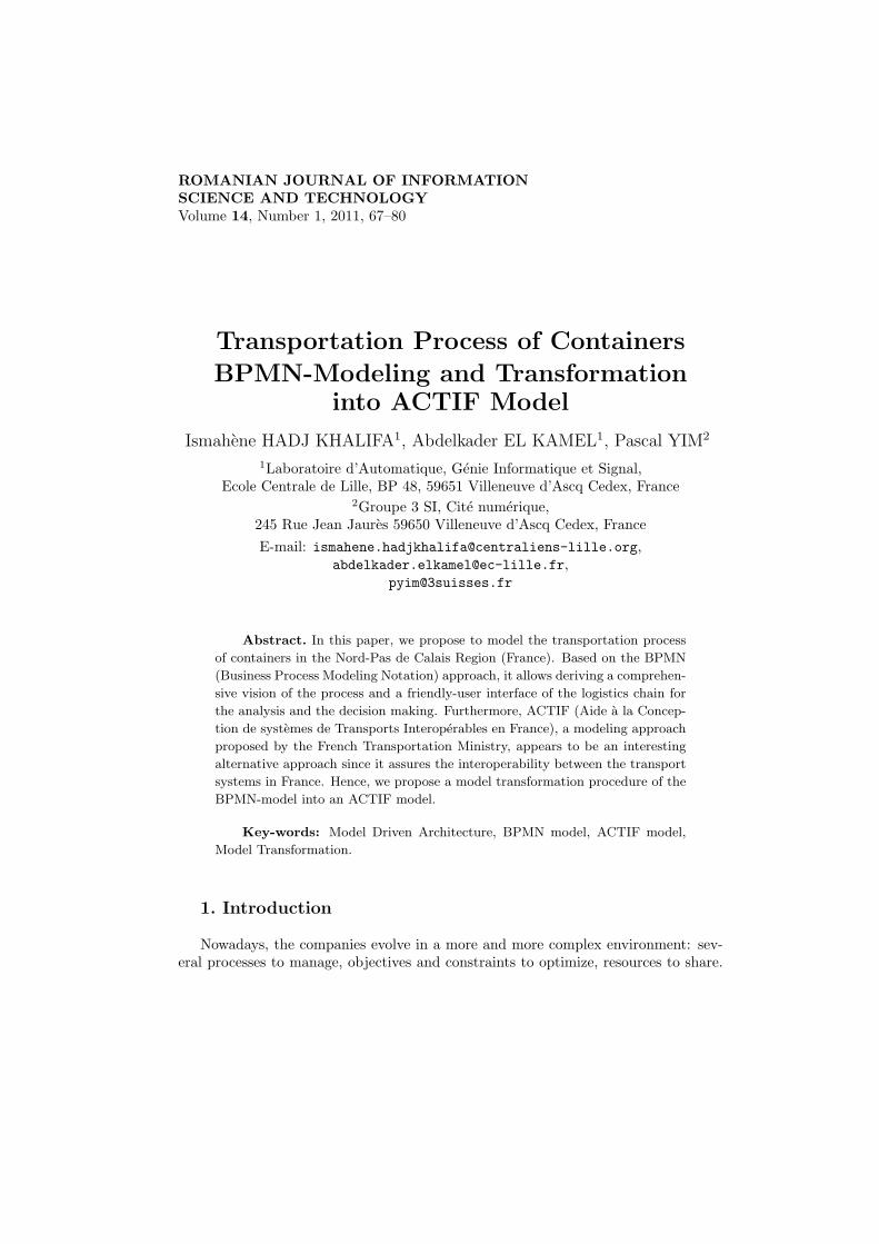
The actors are represented by Pools with their activities. The process begins withan empty circle representing a start event. Then, we represent the activities of eachactor in the corresponding pool. Moreover, we use intermediate events such as:
Transportation Process of Containers BPMN-Modeling 73
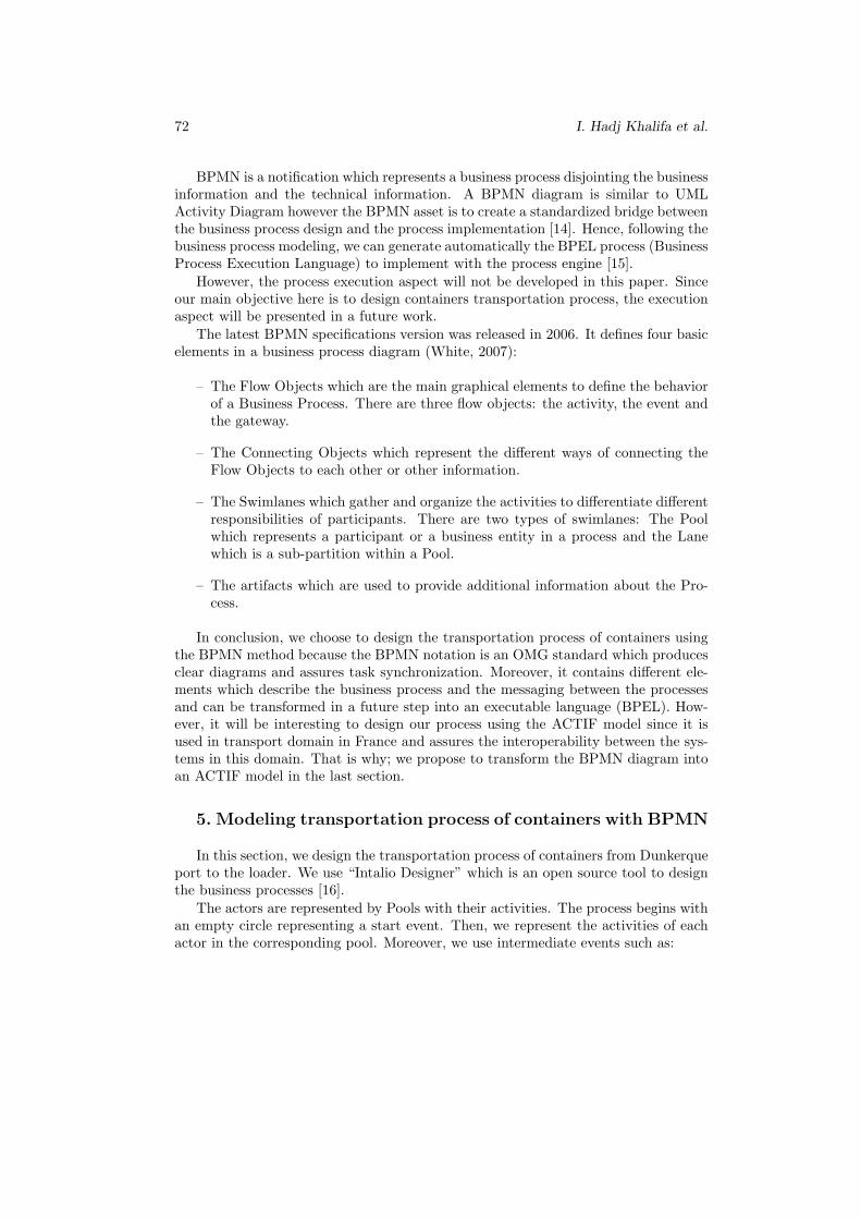
– The “Message” represented inside the “Pool LDCT”. It means that this actormust wait until he receives an e-mail from the NCS actor to execute the activity“Unloading of the barge”.
– The “Timing” is used in the same pool. It means that LDCT must wait 5 to30 minutes to go to the “Pile maritime”. Figure 1 illustrates this.
Furthermore, inside the “Pool LDCT”, there is a gateway used to represent twoactivities setting in the same time.
Fig. 1. Use of intermediate events and gateway.
We use Sequence Flow to connect two Flow Objects if they are inside the samePool. Else, we use Message Flow. Finally, we finish the diagram with an end event.
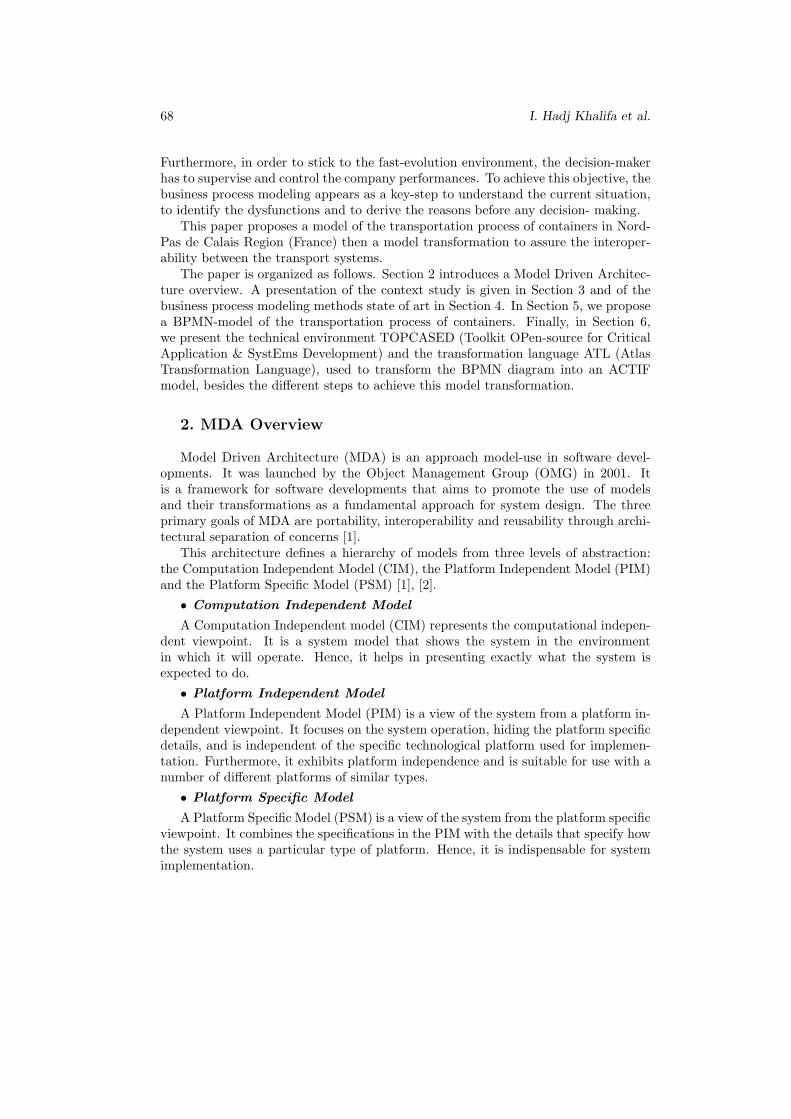
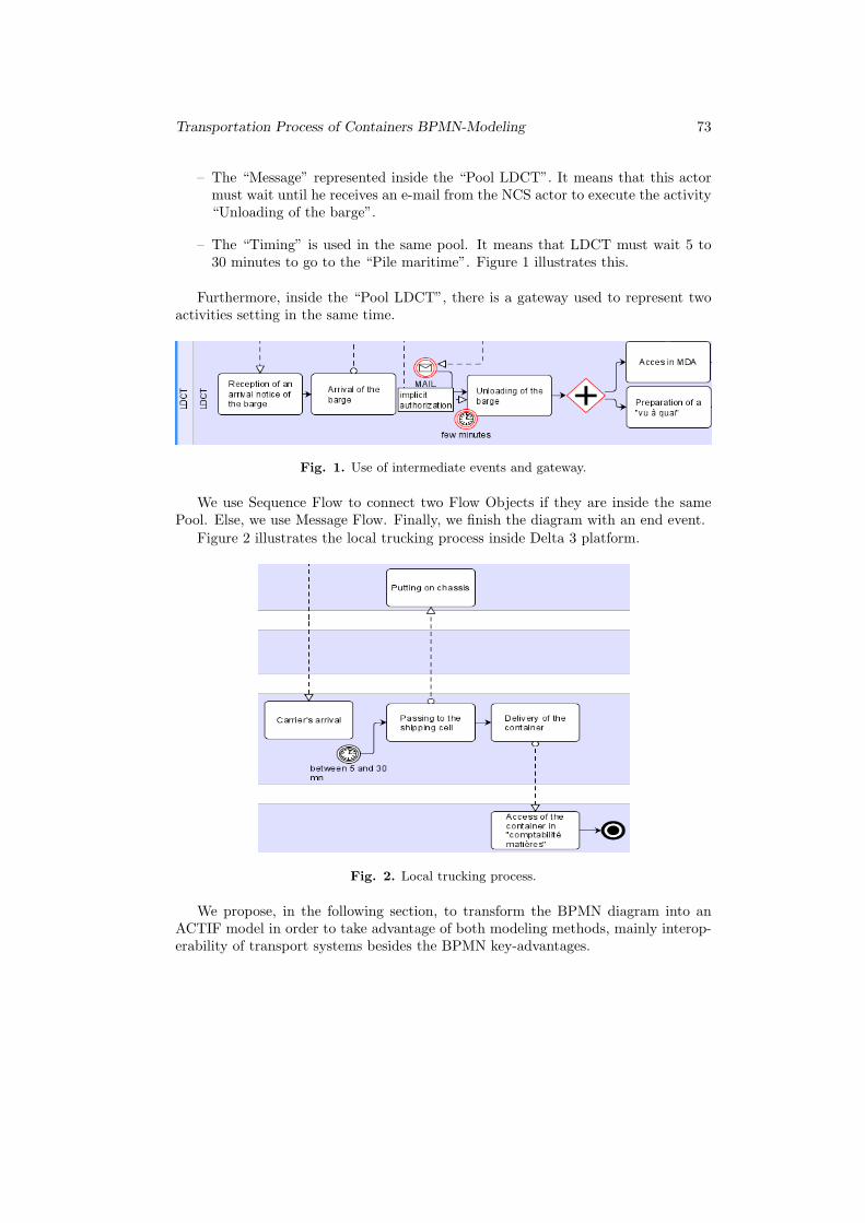
Figure 2 illustrates the local trucking process inside Delta 3 platform.
Fig. 2. Local trucking process.
We propose, in the following section, to transform the BPMN diagram into anACTIF model in order to take advantage of both modeling methods, mainly interop-erability of transport systems besides the BPMN key-advantages.
74 I. Hadj Khalifa et al.
6. Transforming BPMN diagram into ACTIF model
6.1. Technical environment description
We choose TOPCASED environment to create the source and target meta-models,to generate the model corresponding to the source meta-model and to transform themodels. It is an open source environment based on Eclipse. We download TOP-CASED 1.0.0. version available in the website http://gforge.enseeiht.fr/frs/
?group id=7.It is an integrated System/Software engineering toolkit compliant with the require-
ments of critical and embedded applications. It is a result of TOPCASED projectwhich was made to encourage tools cooperation. Its main goals are to perpetuatemethods and tools for system and software development, to ensure the independenceof development platforms, to be able to adapt the tools to the process, and to takeinto account qualification constraints [17].
TOPCASED is strongly model-oriented. So, it provides the model editors, themodel checkers and the model transformations and it is itself based on modeling andcode generation. Furthermore, we can develop our own graphical editors and modeltransformations. To do that, TOPCASED uses tools based on MDA, MDE (ModelDriven Engineering) and QVT (Queries Views Transformations) norms [18].
In TOPCASEE project, several tools open source were tested such as MTF,ATL and MTL. However, ATL seems to be the most interesting since it is complyingwith OMG/MDA/MOF/QVT and we can use it with an open source tool. Further-more, it respects the OMG standards since it is built on top of OCL. In consequence,ATL was chosen to transform models in TOPCASED environment [18].
ATL is a transformation language proposed and developed by ATLAS INRIA &LINA. It is hybrid since it contains a mixture of declarative and imperative constructs.Furthermore, ATL transformations are unidirectional, operating on read-only sourcemodels and producing a write-only target model [19].
An ATL transformation contains three parts [19], [20]:
• The header
It is used to declare general information such as the module name, the input andoutput meta-model names.
• The helpers
The helpers are functions based on OCL standard. They have a name, a contextand a type. OCL defines two kinds of helpers: operation helpers and attribute helpers.
• The rules
The rules are the core of ATL transformations because they describe how elementsof a source model should be translated into elements of a target model. So, theyexpress a mapping between an input element and an output element. They may bespecified either in an imperative style or in a declarative style.
Several transformations were realized using ATL such as “EMF to KM3”, “Grafcetto PetriNet”, “MOF to UML”, “UML to Java”. These transformations are availableon the website http://www.eclipse.org/m2m/atl/atlTransformations/.
Transportation Process of Containers BPMN-Modeling 75
Furthermore, a recent article [21] presents a transformation GRAI into UML Ac-tivity Diagram. For this, Grangel and Al. present the mapping between source modelelements and target model elements. After that, they define the helpers such as ahelper to test whether a GRAI activity has subactivities or not. So, a GRAI activityis transformed into a UML Action if it does not have subactivities, otherwise it istransformed into a UML CallBehaviorAction and its called Activity.
6.2 Transformation of the BPMN model into an ACTIF model
To transform the BPMN model into an ACTIF model, we must follow these steps:
Step 1: Creation of the source and target meta-models
Step 2: Creation of the transformation rulesStep 3: Creation of the source model
Step 4: ConfigurationStep 5: Result
Step 1: Creation of the source and target meta-models. We created themeta-models in ECORE format using TOPCASED ECORE diagrams.
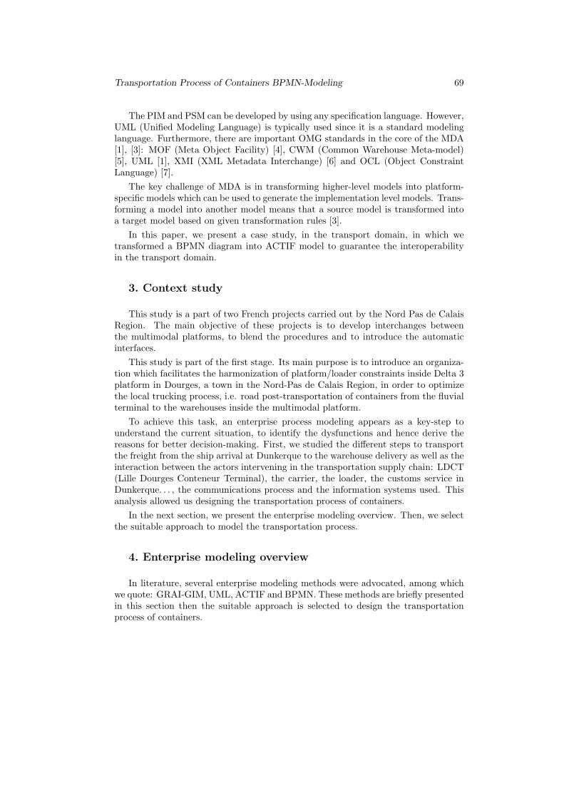
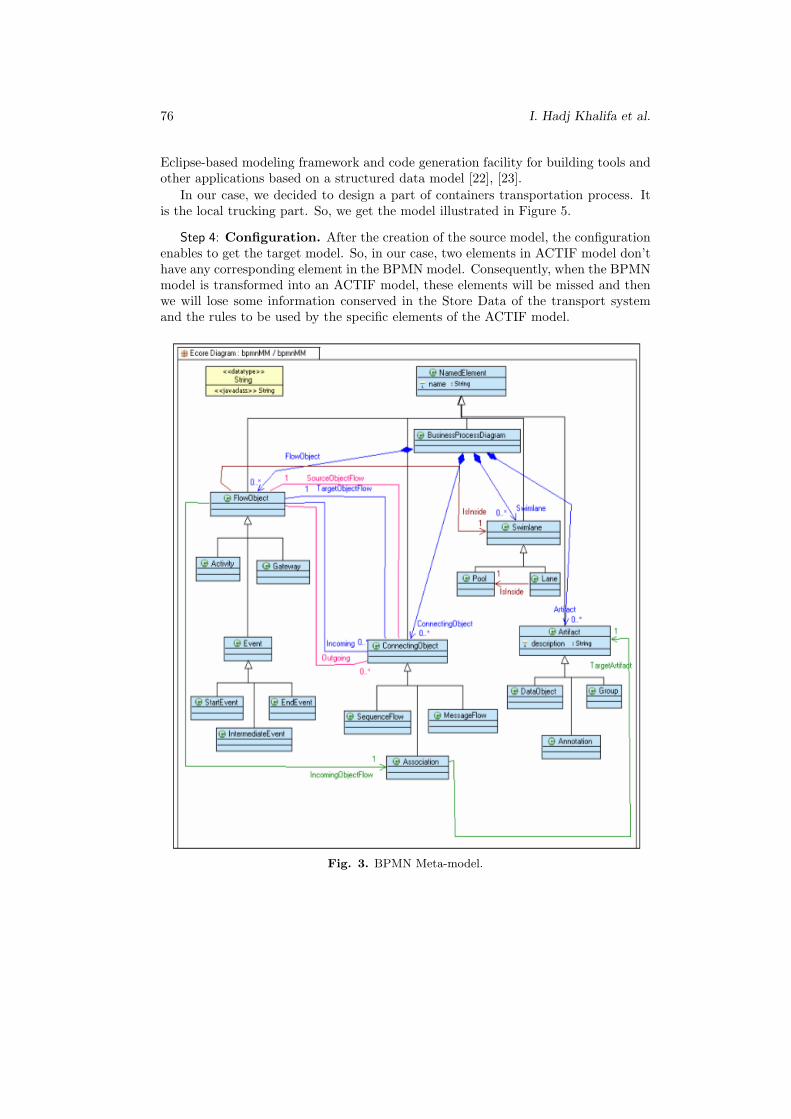
◦ Creation of the source meta-model. We remember that a BPMN diagram con-tains the Flow Objects, the Connecting Objects, the Swimlanes and the Artifacts.A Flow Object can be an Activity, a Gateway or an Event. There are three kindsof Events: Start, Intermediate or End Event. There are three types of ConnectingObjects: the Sequence Flow, the Message Flow and the Association. Pools and Laneare two kinds of Swimlane. We use the Sequence Flow to connect two Flow Objectsif they are inside the same Pool. Else, we use the Message Flow. An Associationlinks a Flow Object to an Artifact. These elements form the BPMN meta-model. Itis illustrated by Figure 3.
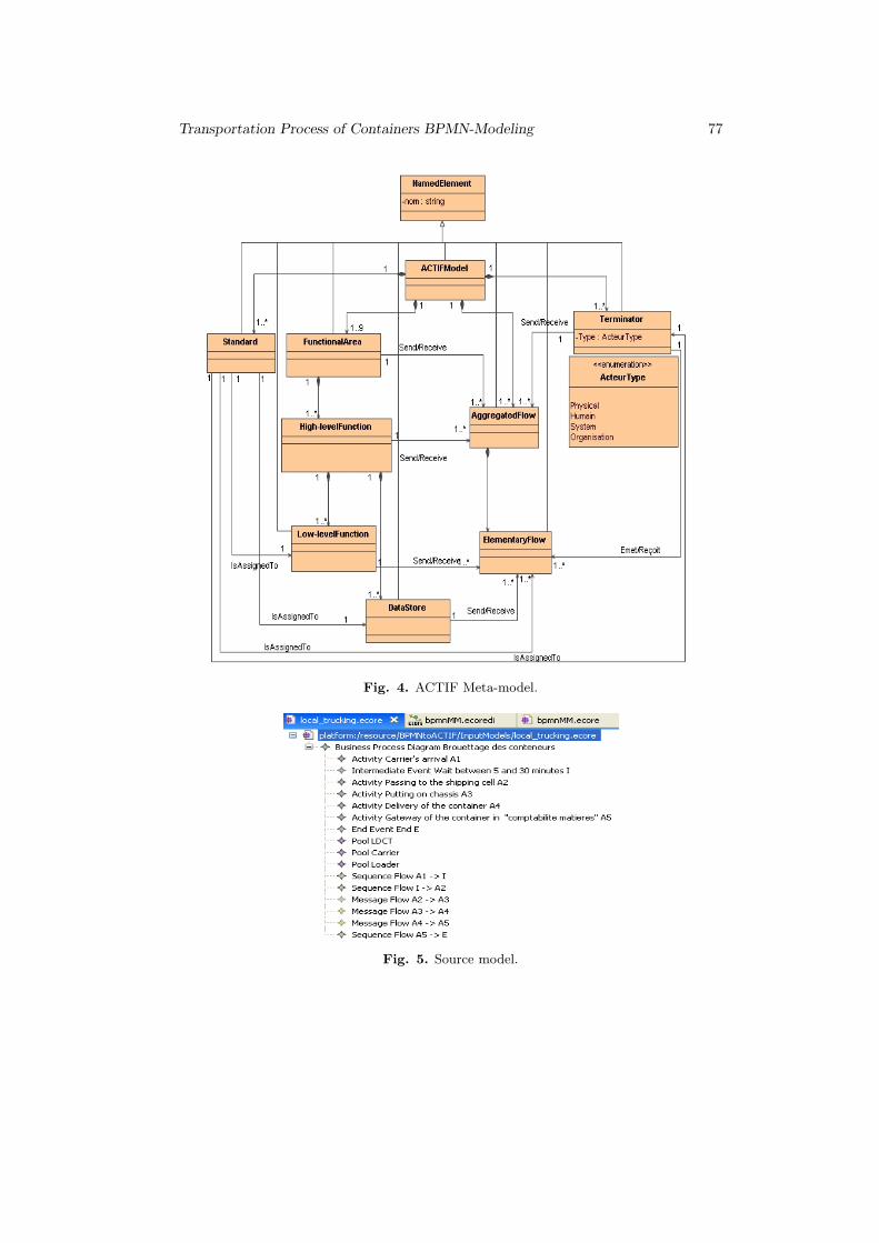
◦ Creation of the target meta-model. To create the ACTIF meta-model, severaldiscussions were made with the chief of the ACTIF project to define the good meta-model. The ACTIF model contains nine Functional Areas, high-level functions andlow-level functions, Data Stores, Logical Flow and Terminators. The meta-modelACTIF is illustrated by Figure 4.
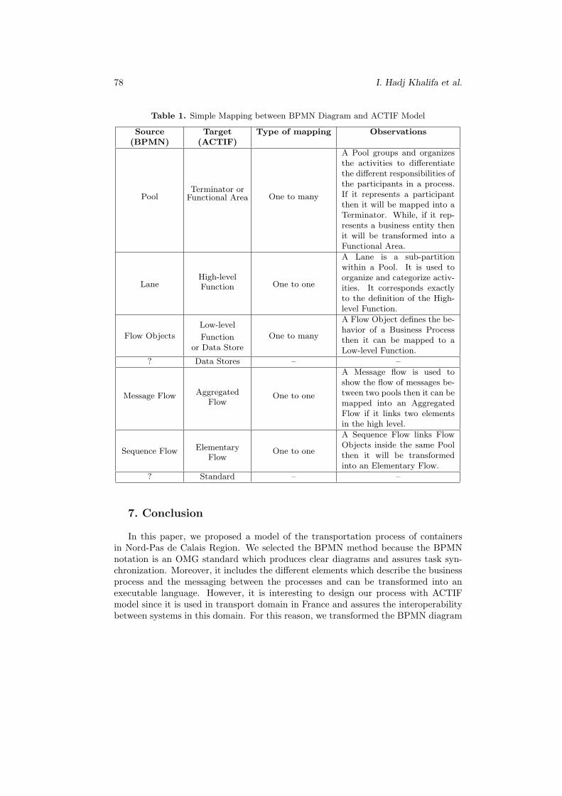
Step 2: Creation of the transformation rules. Transformation rules describehow a Source Model is transformed into a Target Model. Table 1 describes themapping between them.
We didn’t find the corresponding element of the Data Store in the BPMN model.It can be considered like a Low-level Function but it is designed to conserve andprovide information processed in the transport system. Furthermore, the Standardswhich represent the rules to be used by the specific elements of the ACTIF modelhaven’t any corresponding element in BPMN model. So, when we transform theBPMN model into an ACTIF model, these elements will be missed.
Step 3: Creation of the source model. To create the source model, we use theEMF (Eclipse Modeling Framework) to define and execute the data model. It is an
76 I. Hadj Khalifa et al.
Eclipse-based modeling framework and code generation facility for building tools andother applications based on a structured data model [22], [23].
In our case, we decided to design a part of containers transportation process. Itis the local trucking part. So, we get the model illustrated in Figure 5.
Step 4: Configuration. After the creation of the source model, the configurationenables to get the target model. So, in our case, two elements in ACTIF model don’thave any corresponding element in the BPMN model. Consequently, when the BPMNmodel is transformed into an ACTIF model, these elements will be missed and thenwe will lose some information conserved in the Store Data of the transport systemand the rules to be used by the specific elements of the ACTIF model.
Fig. 3. BPMN Meta-model.
Transportation Process of Containers BPMN-Modeling 77
Fig. 4. ACTIF Meta-model.
Fig. 5. Source model.
78 I. Hadj Khalifa et al.
Table 1. Simple Mapping between BPMN Diagram and ACTIF Model
Source(BPMN)
Target(ACTIF)
Type of mapping Observations
PoolTerminator orFunctional Area One to many
A Pool groups and organizesthe activities to differentiatethe different responsibilities ofthe participants in a process.If it represents a participantthen it will be mapped into aTerminator. While, if it rep-resents a business entity thenit will be transformed into aFunctional Area.
LaneHigh-levelFunction One to one
A Lane is a sub-partitionwithin a Pool. It is used toorganize and categorize activ-ities. It corresponds exactlyto the definition of the High-level Function.
Flow Objects
Low-level
Functionor Data Store
One to many
A Flow Object defines the be-havior of a Business Processthen it can be mapped to aLow-level Function.
? Data Stores – –
Message Flow AggregatedFlow
One to one
A Message flow is used toshow the flow of messages be-tween two pools then it can bemapped into an AggregatedFlow if it links two elementsin the high level.
Sequence Flow ElementaryFlow
One to one
A Sequence Flow links FlowObjects inside the same Poolthen it will be transformedinto an Elementary Flow.
? Standard – –
7. Conclusion
In this paper, we proposed a model of the transportation process of containersin Nord-Pas de Calais Region. We selected the BPMN method because the BPMNnotation is an OMG standard which produces clear diagrams and assures task syn-chronization. Moreover, it includes the different elements which describe the businessprocess and the messaging between the processes and can be transformed into anexecutable language. However, it is interesting to design our process with ACTIFmodel since it is used in transport domain in France and assures the interoperabilitybetween systems in this domain. For this reason, we transformed the BPMN diagram
Transportation Process of Containers BPMN-Modeling 79
into an ACTIF model. To carry out this task, we used TOPCASED as a transforma-tion environment and ATL as a transformation language. After creating the sourcemeta-model and the target meta-model with TOPCASED Diagram, we proposed amapping between them. However, transforming models is not evident since in ourcase, there is any corresponding element in the source meta-model for Standards andData Stores. Consequently, we risk losing information.
Hence, it will be interesting to concentrate on this, in the coming researches, be-cause designing using the ACTIF model allows the company to interoperate with theother actors in the transport domain and designing using BPMN, an OMG standard,allows the enterprise to understand better the current situation before making anydecision.
Acknowledgments. We wish to thank M. Alain Demeunynck, the General-Secretary of Club Logistique & Transport 59/62, M. Jean Pierre Grassien, the ProjectChief, Mrs. Nelly Severac, the Exploitation Manager of LDCT, and M. Yannick Denis,the ACTIF Project Chief, for their constructive advices.
References
[1] OMG: MDA Guide Version 1.0.1, Document number: omg/2003-06-01 edition,http://www.omg.org/docs/omg/03-06-01.pdf, 2001.
[2] Bezivin, J., Gerard S., Muller P.A., Rioux L., MDA components: Challenges andOpportunities, Workshop on Metamodelling for MDA, pp. 23–41, 2003.
[3] Kadima H., MDA, Conception orientee objet guidee par les modeles, Dunod, Paris,2005.
[4] OMG, Meta Object Facility (MOF) Core Specification, version 2.0, OMG documentformal/06-01-01, http://www.omg.org/docs/formal/06-01-01.pdf
[5] OMG: Common Warehouse Metamodel (CWM) Specification, version 1.1, volume 1.OMG document formal/03-03-02, http://www.omg.org/docs/formal/03-03-02.pdf,2002.
[6] OMG: XML Metadata Interchange (XMI) specification, version 2.0, OMG Documentformal/2003-05-02, http://www.omg.org/cgi-bin/doc?formal/2003-05-02, 2002.
[7] OMG: OCL 2.0 Specification, version 2.0, OMG document ptc/2005-06-06,http://www.omg.org/docs/ptc/05-06-06.pdf, 2006.
[8] Doumeingts G., Vallespir V., Zanettin M., Chen D., GRAI Integrated Methodol-ogy: A Methodology for Designing CIM Systems. Version 1.0, GRAI/LAP, UniversityBordeaux I, 1992.
[9] Pierreval H., Les methodes d’analyse et de conception des systemes de production,Edition Hermes, 1990.
[10] Rumbaugh J., Jacobson I., Booch G., UML 2.0 Guide de reference, Edition Cam-pusPress, deuxieme edition, 2005.
[11] OMG: Unified Modeling Language: Superstructure. Version 2.0, formal/05-07-04, 2004.
[12] ACTIF, website of the project ACTIF, http://www.its-actif.org
[13] BPMN: Business Process Modelling Notation Specification, May 2004.
80 I. Hadj Khalifa et al.
[14] BPMN: Business Process Modelling Notation Specification, February 2006.
[15] White A. S., Using BPMN to Model a BPEL Process, IBM Corporation, 2007.
[16] Helkio P., Seppala A., Syd O., Evaluation of Intalio BPM Tool, Special Course inInformation System Integration, 2006.
[17] Farail P., Gaufillet P., TOPCASED un environnement de developpement OpenSource pour les systemes embarques, article published by TOPCASED consortium mem-bers, http://www.topcased.org/, 2005.
[18] Canals A., Le-Camus C., Feau M., Jolly G., Bonnafous V., Bazavan P., Uneutilisation operationnelle d’ATL : l’integration de la transformation de modeles dansle projet TOPCASED, article published by the TOPCASED consortium members,http://www.topcased.org/, 2005.
[19] Jouault F., Kurtev I., Transforming Models with ATL, Proceedings of the ModelTransformations in Practice Workshop, MoDELS 2005, Montego Bay, Jamaica, 2005.
[20] Allilaire F., Bezivin J., Jouault F., Kurtev I., ATL: Eclipse Support for ModelTransformation, Proceedings of the Eclipse Technology eXchange Workshop (eTX) atthe ECOOP 06 Conference, Nantes, France, 2006.
[21] Grangel R., Ben Salem R., Bourey J. P., Daclin N., Ducq Y., TransformingGRAI Extended Actigrams into UML Activity Diagrams: a First Step to Model DrivenInteroperability, 3rd International Conference, Interoperability for Enterprise Softwareand Applications, I-ESA 07, Portugal, March 2007.
[22] Parrend P., Introduction pratique au Developpement oriente Modele, March 2005.
[23] Catherine G., Using EMF, IBM, May 2003.