Embed Size (px)
Citation preview
1 Configuring Transparent Firewall via Cisco ASDM © 2008 Cisco Systems, Inc.
Configuring Transparent Firewall via Cisco ASDM Created by Bob Eckhoff
This study aid provides an overview and explanation of transparent firewall mode. It also covers how to enable the transparent firewall and the monitoring and maintenance commands that are specific to the transparent firewall mode.
Transparent Firewall Mode Overview This topic provides an overview of the transparent firewall mode.
© 2008 Cisco Systems, Inc. All rights reserved. 1
Routed vs. Transparent Mode
The security appliance can run in two modes:Routed: Based on IP addressTransparent: Based on MAC address
10.0.1.0VLAN 100
10.0.1.0VLAN 200
Transparent Mode
10.0.1.0VLAN 100
10.0.2.0VLAN 200
Routed Mode
g0/0
g0/1 g0/1
g0/0
Traditionally, a firewall is a routed hop and acts as a default gateway for hosts that connect to one of its screened subnets. A transparent firewall, on the other hand, is a Layer 2 firewall that acts like a “bump in the wire” or a “stealth firewall” and is not seen as a router hop to connected devices. The security appliance connects the same network on its inside and outside ports, but each interface resides on a different broadcast domain and the security appliance performs secured transparent bridging between the two broadcast domains.
Because the security appliance is not a routed hop, you can easily introduce a transparent firewall into an existing network. IP readdressing is unnecessary, and maintenance is facilitated because there are no complicated routing patterns to troubleshoot.
2 Configuring Transparent Firewall via Cisco ASDM © 2008 Cisco Systems, Inc.
© 2008 Cisco Systems, Inc. All rights reserved. 2
Transparent Mode
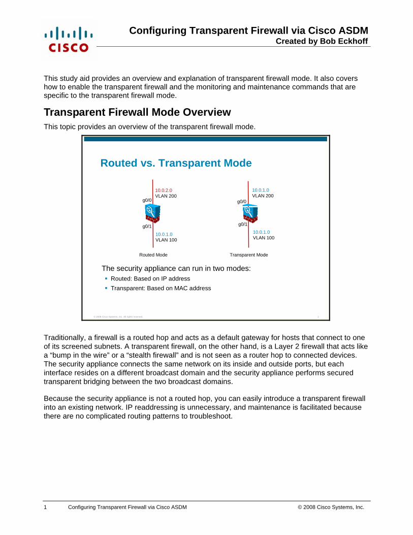
Easily integrated and maintained in the existing networkNo IP routing to troubleshootSupports only two data interfacesRequires only one IP addressBridges packets from one VLAN to the otherPerforms MAC lookups instead of routing table lookupsCan pass traffic that cannot be passed by a security appliance in routed mode
10.0.1.0VLAN 100
10.0.1.0VLAN 200
Layer 2 Deviceg0/0
g0/1
Management IP address: 10.0.1.1
Bridging
A security appliance in transparent mode is easily integrated and maintained in the existing network because IP readdressing is not necessary and there is no IP routing to troubleshoot. However, before implementing transparent mode, it is important to fully understand its functionality. A security appliance running in transparent mode and a security appliance running in routed mode both support security levels on the interfaces and can run in either single or multiple context mode; however, a security appliance running in transparent mode differs from the routed mode security appliance in the following ways:
Supports only two data interfaces: The transparent security appliance uses an inside interface and an outside interface only. If your platform includes a dedicated management interface, you can also configure the management interface or subinterface for management traffic only.
Requires only one IP address: Unlike routed mode, which requires an IP address for each interface, a transparent firewall has an IP address assigned to the entire device.
Bridges packets from one interface/VLAN to the other: Instead of routing packets from one interface/VLAN to another, the security appliance running in transparent mode bridges them.
Performs MAC address lookups instead of routing table lookups: When the security appliance runs in transparent mode without Network Address Translation (NAT), the outgoing interface of a packet is determined by performing a MAC address lookup instead of a route lookup. Route statements can still be configured, but they only apply to security appliance-originated traffic. For example, if your syslog server is located on a remote network, you must use a static route so the security appliance can reach the remote network.
Can pass traffic that cannot be passed by a security appliance in routed mode: Certain types of traffic that cannot be allowed to traverse the security appliance in routed mode can be allowed in transparent mode.
3 Configuring Transparent Firewall via Cisco ASDM © 2008 Cisco Systems, Inc.
© 2008 Cisco Systems, Inc. All rights reserved. 3
Allowing Traffic to Traverse a Security Appliance in Transparent Mode
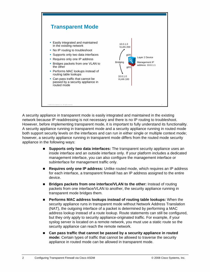
IPv4 traffic is generally handled as it is in routed mode.Certain types of traffic that cannot be allowed to traverse the security appliance in routed mode can be allowed in transparent mode. For example, routing protocols such as OSPF and EIGRP can be permitted by using an ACL.Non-IP traffic such as the following can be allowed by EtherType ACLs:– AppleTalk– IPX– BPDUs– MPLS
ARP is allowed in both directions without an ACL.
g0/1
10.0.1.1
security level 100
g0/0security level 0
IPv4(ACL
required)IPv4
Like routed mode, transparent mode supports security levels on the interfaces. IP version 4 (IPv4) traffic is allowed through and inspected by the transparent mode security appliance from a higher security interface to a lower security interface without an access control list (ACL); for layer 3 traffic traveling from a lower security interface to a higher security interface, an extended ACL is required.
However, certain types of traffic that cannot be allowed to traverse the security appliance in routed mode can be allowed in transparent mode. In routed mode, some types of traffic cannot pass through the security appliance even if you allow it in an ACL. The transparent firewall, on the other hand, can allow almost any traffic through using either an extended ACL or an ethertype ACL. The security appliance can inspect IP packets only; no inspection is possible for non-IP ethertypes. However, from a bridging perspective, the security appliance can bridge non-IP packets from one interface to another.
For example, you can establish routing protocol adjacencies through a transparent firewall; you can allow Open Shortest Path First (OSPF) or Enhanced Interior Gateway Routing Protocol (EIGRP) traffic through based on an extended ACL. For EIGRP and OSPF, since they have their own protocol number and don’t use TCP or User Datagram Protocol (UDP) at the transport layer, they are treated as stateless protocols like Encapsulating Security Payload (ESP) and (Generic Routing Encapsulation (GRE). Likewise, protocols like Hot Standby Router Protocol (HSRP) or Virtual Router Redundancy Protocol (VRRP) can pass through the security appliance. Ethertype ACLs enable you to allow traffic that is not IP traffic, such as AppleTalk, (Internetwork Packet Exchange) IPX, bridge protocol data units (BPDUs), and Multiprotocol Label Switching (MPLS) through the security appliance. The ACL should be applied to both inbound and outbound interfaces in the “in” direction to allow bidirectional traffic flow.
Address Resolution Protocol (ARP) packets are allowed through the transparent firewall in both directions without an access list. You can control the flow of ARP packets by optionally enabling ARP inspection.
4 Configuring Transparent Firewall via Cisco ASDM © 2008 Cisco Systems, Inc.
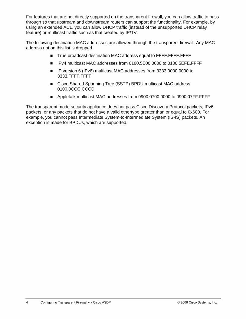
For features that are not directly supported on the transparent firewall, you can allow traffic to pass through so that upstream and downstream routers can support the functionality. For example, by using an extended ACL, you can allow DHCP traffic (instead of the unsupported DHCP relay feature) or multicast traffic such as that created by IP/TV.
The following destination MAC addresses are allowed through the transparent firewall. Any MAC address not on this list is dropped.
True broadcast destination MAC address equal to FFFF.FFFF.FFFF
IPv4 multicast MAC addresses from 0100.5E00.0000 to 0100.5EFE.FFFF
IP version 6 (IPv6) multicast MAC addresses from 3333.0000.0000 to 3333.FFFF.FFFF
Cisco Shared Spanning Tree (SSTP) BPDU multicast MAC address 0100.0CCC.CCCD
Appletalk multicast MAC addresses from 0900.0700.0000 to 0900.07FF.FFFF
The transparent mode security appliance does not pass Cisco Discovery Protocol packets, IPv6 packets, or any packets that do not have a valid ethertype greater than or equal to 0x600. For example, you cannot pass Intermediate System-to-Intermediate System (IS-IS) packets. An exception is made for BPDUs, which are supported.
5 Configuring Transparent Firewall via Cisco ASDM © 2008 Cisco Systems, Inc.
© 2008 Cisco Systems, Inc. All rights reserved. 4
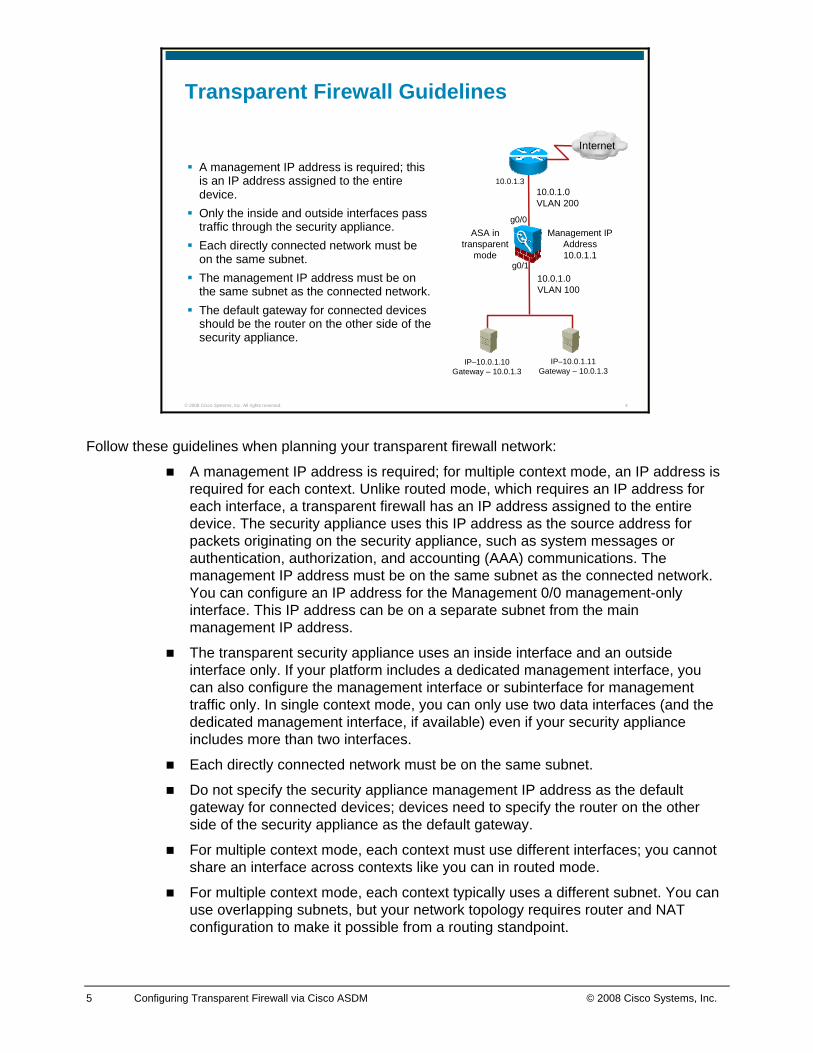
Transparent Firewall Guidelines
A management IP address is required; this is an IP address assigned to the entire device.Only the inside and outside interfaces pass traffic through the security appliance.Each directly connected network must be on the same subnet.The management IP address must be on the same subnet as the connected network.The default gateway for connected devices should be the router on the other side of the security appliance.
10.0.1.0VLAN 200
10.0.1.0VLAN 100
ASA in transparent
mode
Management IP Address10.0.1.1
10.0.1.3
IP–10.0.1.10Gateway – 10.0.1.3
IP–10.0.1.11Gateway – 10.0.1.3
Internet
g0/0
g0/1
Follow these guidelines when planning your transparent firewall network:
A management IP address is required; for multiple context mode, an IP address is required for each context. Unlike routed mode, which requires an IP address for each interface, a transparent firewall has an IP address assigned to the entire device. The security appliance uses this IP address as the source address for packets originating on the security appliance, such as system messages or authentication, authorization, and accounting (AAA) communications. The management IP address must be on the same subnet as the connected network. You can configure an IP address for the Management 0/0 management-only interface. This IP address can be on a separate subnet from the main management IP address.
The transparent security appliance uses an inside interface and an outside interface only. If your platform includes a dedicated management interface, you can also configure the management interface or subinterface for management traffic only. In single context mode, you can only use two data interfaces (and the dedicated management interface, if available) even if your security appliance includes more than two interfaces.
Each directly connected network must be on the same subnet.
Do not specify the security appliance management IP address as the default gateway for connected devices; devices need to specify the router on the other side of the security appliance as the default gateway.
For multiple context mode, each context must use different interfaces; you cannot share an interface across contexts like you can in routed mode.
For multiple context mode, each context typically uses a different subnet. You can use overlapping subnets, but your network topology requires router and NAT configuration to make it possible from a routing standpoint.
6 Configuring Transparent Firewall via Cisco ASDM © 2008 Cisco Systems, Inc.
© 2008 Cisco Systems, Inc. All rights reserved. 5
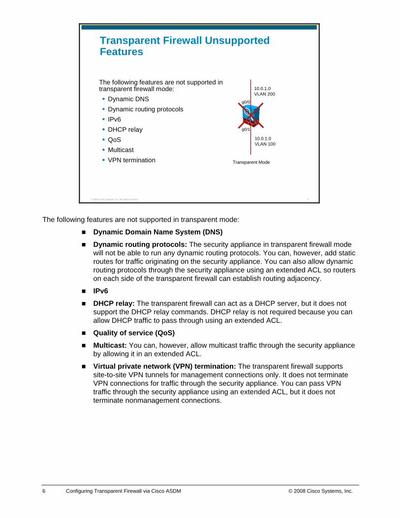
Transparent Firewall Unsupported Features
The following features are not supported in transparent firewall mode:
Dynamic DNSDynamic routing protocols IPv6DHCP relay QoSMulticast VPN termination
10.0.1.0VLAN 200
10.0.1.0VLAN 100
Transparent Mode
g0/0
g0/1
The following features are not supported in transparent mode:
Dynamic Domain Name System (DNS) Dynamic routing protocols: The security appliance in transparent firewall mode
will not be able to run any dynamic routing protocols. You can, however, add static routes for traffic originating on the security appliance. You can also allow dynamic routing protocols through the security appliance using an extended ACL so routers on each side of the transparent firewall can establish routing adjacency.
IPv6 DHCP relay: The transparent firewall can act as a DHCP server, but it does not
support the DHCP relay commands. DHCP relay is not required because you can allow DHCP traffic to pass through using an extended ACL.
Quality of service (QoS) Multicast: You can, however, allow multicast traffic through the security appliance
by allowing it in an extended ACL.
Virtual private network (VPN) termination: The transparent firewall supports site-to-site VPN tunnels for management connections only. It does not terminate VPN connections for traffic through the security appliance. You can pass VPN traffic through the security appliance using an extended ACL, but it does not terminate nonmanagement connections.
7 Configuring Transparent Firewall via Cisco ASDM © 2008 Cisco Systems, Inc.
How Data Traverses a Security Appliance in Transparent Mode This topic describes how data traverses a transparent mode security appliance in the inbound and outbound directions, with and without NAT.
© 2008 Cisco Systems, Inc. All rights reserved. 7
Outbound Connections
Management IP Address10.0.1.1
10.0.1.3
IP–10.0.1.10Gateway – 10.0.1.3
IP–10.0.1.11Gateway – 10.0.1.3
g0/0
g0/1
example.com
Internet
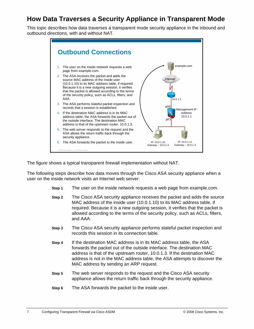
1. The user on the inside network requests a web page from example.com.
2. The ASA receives the packet and adds the source MAC address of the inside user (10.0.1.10) to its MAC address table, if required. Because it is a new outgoing session, it verifies that the packet is allowed according to the terms of the security policy, such as ACLs, filters, and AAA.
3. The ASA performs stateful packet inspection and records that a session is established.
4. If the destination MAC address is in its MAC address table, the ASA forwards the packet out of the outside interface. The destination MAC address is that of the upstream router, 10.0.1.3.
5. The web server responds to the request and the ASA allows the return traffic back through the security appliance.
6. The ASA forwards the packet to the inside user.
The figure shows a typical transparent firewall implementation without NAT.
The following steps describe how data moves through the Cisco ASA security appliance when a user on the inside network visits an Internet web server:
Step 1 The user on the inside network requests a web page from example.com.
Step 2 The Cisco ASA security appliance receives the packet and adds the source MAC address of the inside user (10.0.1.10) to its MAC address table, if required. Because it is a new outgoing session, it verifies that the packet is allowed according to the terms of the security policy, such as ACLs, filters, and AAA.
Step 3 The Cisco ASA security appliance performs stateful packet inspection and records this session in its connection table.
Step 4 If the destination MAC address is in its MAC address table, the ASA forwards the packet out of the outside interface. The destination MAC address is that of the upstream router, 10.0.1.3. If the destination MAC address is not in the MAC address table, the ASA attempts to discover the MAC address by sending an ARP request.
Step 5 The web server responds to the request and the Cisco ASA security appliance allows the return traffic back through the security appliance.
Step 6 The ASA forwards the packet to the inside user.
8 Configuring Transparent Firewall via Cisco ASDM © 2008 Cisco Systems, Inc.
© 2008 Cisco Systems, Inc. All rights reserved. 8
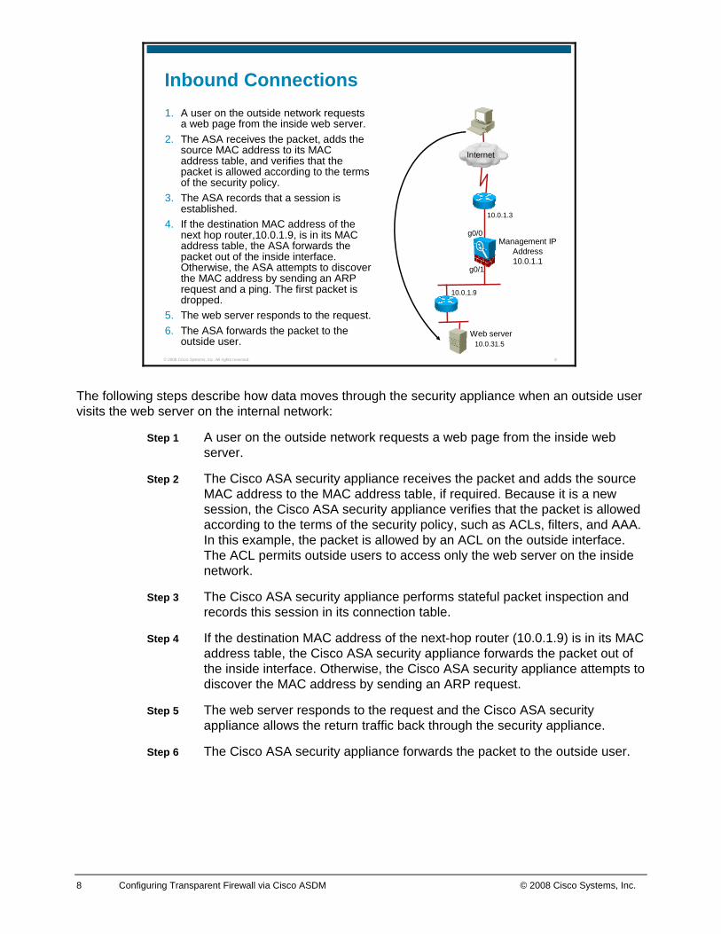
Inbound Connections1. A user on the outside network requests
a web page from the inside web server. 2. The ASA receives the packet, adds the
source MAC address to its MAC address table, and verifies that the packet is allowed according to the terms of the security policy.
3. The ASA records that a session is established.
4. If the destination MAC address of the next hop router,10.0.1.9, is in its MAC address table, the ASA forwards the packet out of the inside interface. Otherwise, the ASA attempts to discover the MAC address by sending an ARP request and a ping. The first packet is dropped.
5. The web server responds to the request. 6. The ASA forwards the packet to the
outside user.
Management IP Address10.0.1.1
10.0.1.3
10.0.1.9
10.0.31.5
g0/0
g0/1
Internet
Web server
The following steps describe how data moves through the security appliance when an outside user visits the web server on the internal network:
Step 1 A user on the outside network requests a web page from the inside web server.
Step 2 The Cisco ASA security appliance receives the packet and adds the source MAC address to the MAC address table, if required. Because it is a new session, the Cisco ASA security appliance verifies that the packet is allowed according to the terms of the security policy, such as ACLs, filters, and AAA. In this example, the packet is allowed by an ACL on the outside interface. The ACL permits outside users to access only the web server on the inside network.
Step 3 The Cisco ASA security appliance performs stateful packet inspection and records this session in its connection table.
Step 4 If the destination MAC address of the next-hop router (10.0.1.9) is in its MAC address table, the Cisco ASA security appliance forwards the packet out of the inside interface. Otherwise, the Cisco ASA security appliance attempts to discover the MAC address by sending an ARP request.
Step 5 The web server responds to the request and the Cisco ASA security appliance allows the return traffic back through the security appliance.
Step 6 The Cisco ASA security appliance forwards the packet to the outside user.
9 Configuring Transparent Firewall via Cisco ASDM © 2008 Cisco Systems, Inc.
Configuring Transparent Firewall Mode This topic explains how to configure a security appliance for transparent mode.
© 2008 Cisco Systems, Inc. All rights reserved. 9
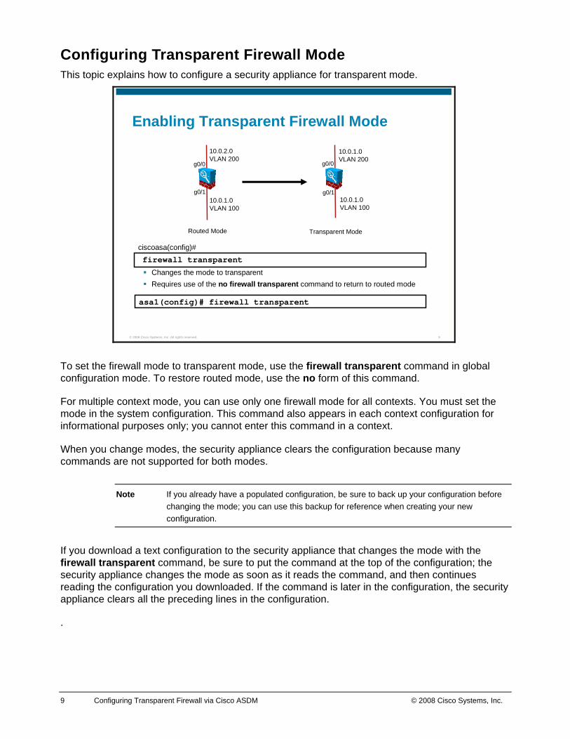
Enabling Transparent Firewall Mode
Changes the mode to transparentRequires use of the no firewall transparent command to return to routed mode
firewall transparentciscoasa(config)#
asa1(config)# firewall transparent
10.0.1.0VLAN 100
10.0.1.0VLAN 200
Transparent Mode
10.0.1.0VLAN 100
10.0.2.0VLAN 200
Routed Mode
g0/0
g0/1
g0/0
g0/1
To set the firewall mode to transparent mode, use the firewall transparent command in global configuration mode. To restore routed mode, use the no form of this command.
For multiple context mode, you can use only one firewall mode for all contexts. You must set the mode in the system configuration. This command also appears in each context configuration for informational purposes only; you cannot enter this command in a context.
When you change modes, the security appliance clears the configuration because many commands are not supported for both modes.
Note If you already have a populated configuration, be sure to back up your configuration before changing the mode; you can use this backup for reference when creating your new configuration.
If you download a text configuration to the security appliance that changes the mode with the firewall transparent command, be sure to put the command at the top of the configuration; the security appliance changes the mode as soon as it reads the command, and then continues reading the configuration you downloaded. If the command is later in the configuration, the security appliance clears all the preceding lines in the configuration.
.
10 Configuring Transparent Firewall via Cisco ASDM © 2008 Cisco Systems, Inc.
© 2008 Cisco Systems, Inc. All rights reserved. 13
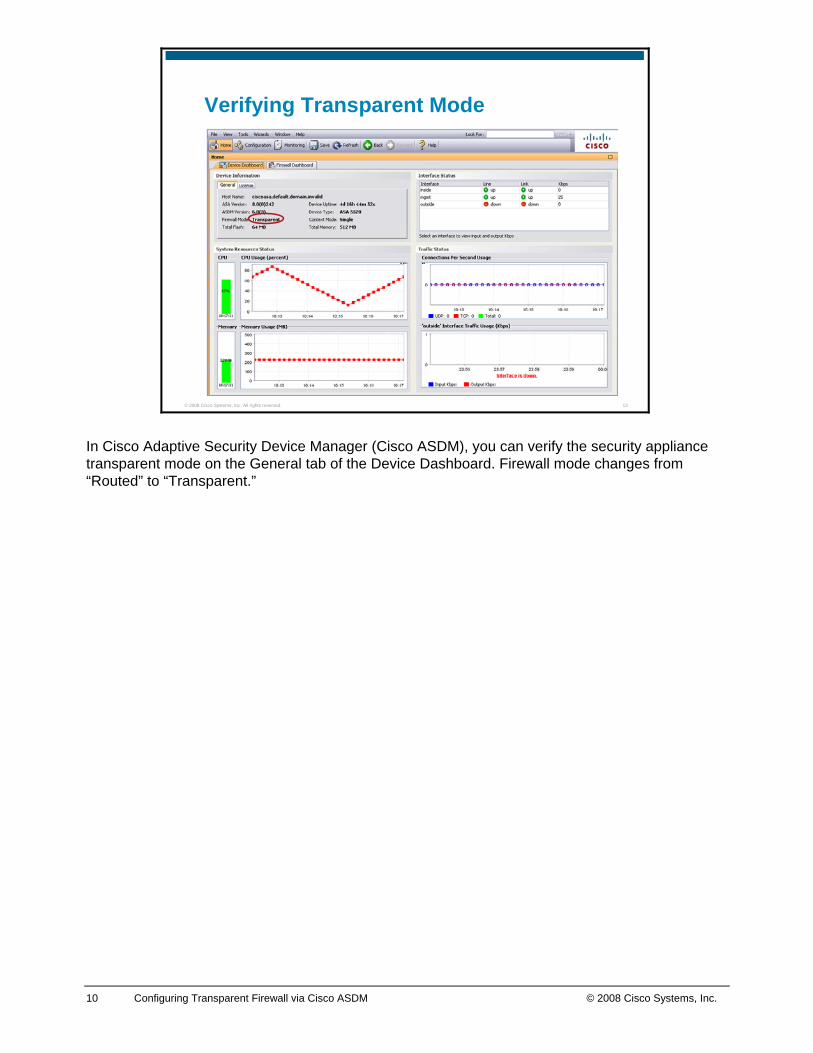
Verifying Transparent Mode
In Cisco Adaptive Security Device Manager (Cisco ASDM), you can verify the security appliance transparent mode on the General tab of the Device Dashboard. Firewall mode changes from “Routed” to “Transparent.”
11 Configuring Transparent Firewall via Cisco ASDM © 2008 Cisco Systems, Inc.
© 2008 Cisco Systems, Inc. All rights reserved. 14
Assigning the Management IP Address10.0.1.10
ASDM
10.0.1.1
Corporate g0/0 g0/1
DeviceManagement
ManagementIP Address
m0/0
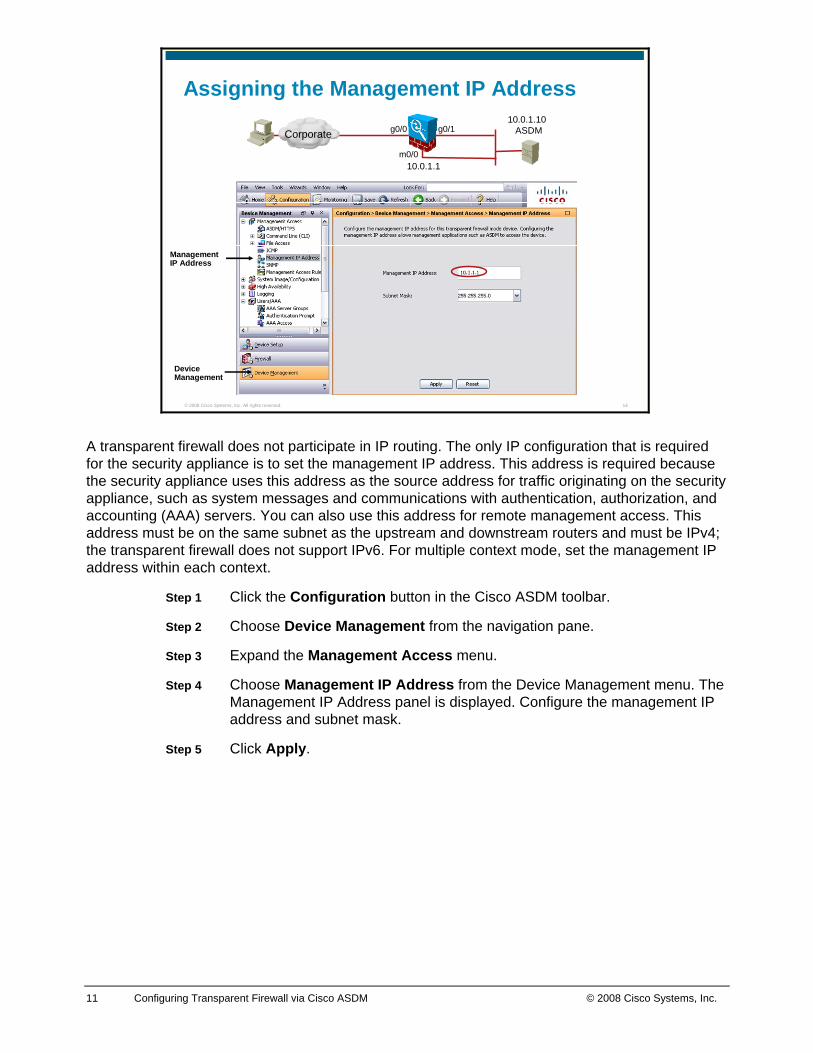
A transparent firewall does not participate in IP routing. The only IP configuration that is required for the security appliance is to set the management IP address. This address is required because the security appliance uses this address as the source address for traffic originating on the security appliance, such as system messages and communications with authentication, authorization, and accounting (AAA) servers. You can also use this address for remote management access. This address must be on the same subnet as the upstream and downstream routers and must be IPv4; the transparent firewall does not support IPv6. For multiple context mode, set the management IP address within each context.
Step 1 Click the Configuration button in the Cisco ASDM toolbar.
Step 2 Choose Device Management from the navigation pane.
Step 3 Expand the Management Access menu.
Step 4 Choose Management IP Address from the Device Management menu. The Management IP Address panel is displayed. Configure the management IP address and subnet mask.
Step 5 Click Apply.
12 Configuring Transparent Firewall via Cisco ASDM © 2008 Cisco Systems, Inc.
© 2008 Cisco Systems, Inc. All rights reserved. 15
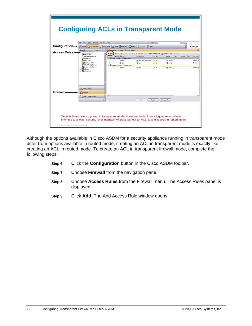
Configuring ACLs in Transparent Mode
Security levels are supported in transparent mode; therefore, traffic from a higher security level interface to a lower security level interface will pass without an ACL, just as it does in routed mode.
Firewall
Configuration
Access Rules
Although the options available in Cisco ASDM for a security appliance running in transparent mode differ from options available in routed mode, creating an ACL in transparent mode is exactly like creating an ACL in routed mode. To create an ACL in transparent firewall mode, complete the following steps:
Step 6 Click the Configuration button in the Cisco ASDM toolbar.
Step 7 Choose Firewall from the navigation pane.
Step 8 Choose Access Rules from the Firewall menu. The Access Rules panel is displayed.
Step 9 Click Add. The Add Access Rule window opens.
13 Configuring Transparent Firewall via Cisco ASDM © 2008 Cisco Systems, Inc.
© 2008 Cisco Systems, Inc. All rights reserved. 13
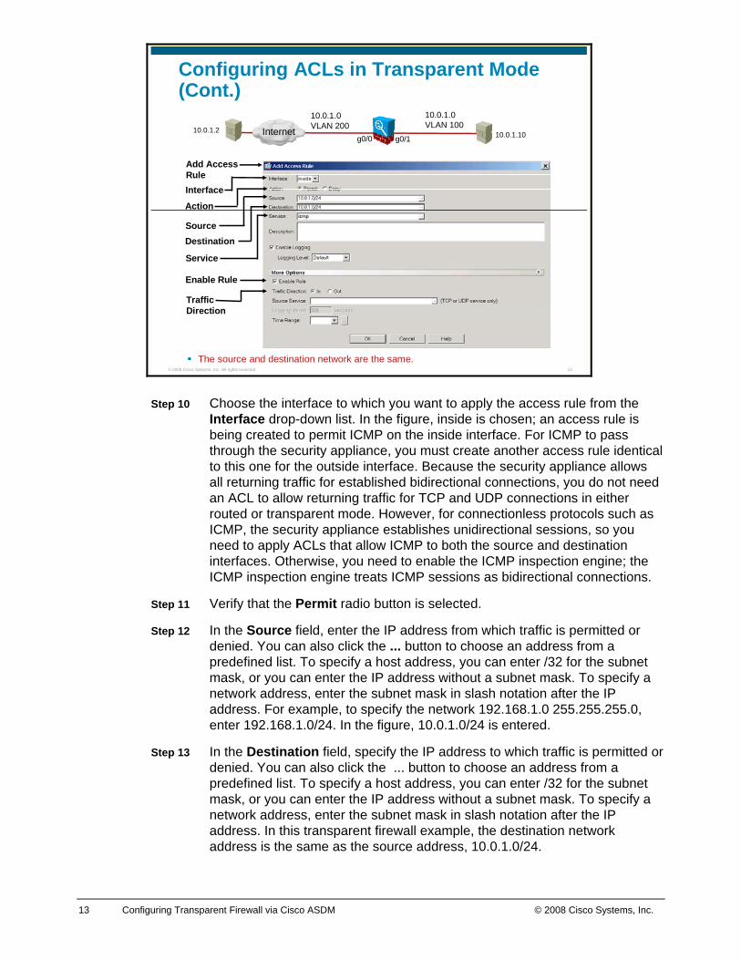
Configuring ACLs in Transparent Mode (Cont.)
10.0.1.2 10.0.1.10
10.0.1.0VLAN 100
10.0.1.0VLAN 200Internet
g0/0 g0/1
Source
Interface
Add Access Rule
Action
Destination
Service
Enable Rule
Traffic Direction
The source and destination network are the same.
Step 10 Choose the interface to which you want to apply the access rule from the Interface drop-down list. In the figure, inside is chosen; an access rule is being created to permit ICMP on the inside interface. For ICMP to pass through the security appliance, you must create another access rule identical to this one for the outside interface. Because the security appliance allows all returning traffic for established bidirectional connections, you do not need an ACL to allow returning traffic for TCP and UDP connections in either routed or transparent mode. However, for connectionless protocols such as ICMP, the security appliance establishes unidirectional sessions, so you need to apply ACLs that allow ICMP to both the source and destination interfaces. Otherwise, you need to enable the ICMP inspection engine; the ICMP inspection engine treats ICMP sessions as bidirectional connections.
Step 11 Verify that the Permit radio button is selected.
Step 12 In the Source field, enter the IP address from which traffic is permitted or denied. You can also click the ... button to choose an address from a predefined list. To specify a host address, you can enter /32 for the subnet mask, or you can enter the IP address without a subnet mask. To specify a network address, enter the subnet mask in slash notation after the IP address. For example, to specify the network 192.168.1.0 255.255.255.0, enter 192.168.1.0/24. In the figure, 10.0.1.0/24 is entered.
Step 13 In the Destination field, specify the IP address to which traffic is permitted or denied. You can also click the ... button to choose an address from a predefined list. To specify a host address, you can enter /32 for the subnet mask, or you can enter the IP address without a subnet mask. To specify a network address, enter the subnet mask in slash notation after the IP address. In this transparent firewall example, the destination network address is the same as the source address, 10.0.1.0/24.
14 Configuring Transparent Firewall via Cisco ASDM © 2008 Cisco Systems, Inc.
Step 14 Specify the service or protocol for the rule in the Service field. You can also click the ... button to choose a service from a predefined list. In the figure, icmp is entered.
Step 15 Click the More Options double arrow to configure additional settings for the rule.
Step 16 Verify that the Enable Rule check box is checked.
Step 17 Choose the In or Out radio button from the Traffic Direction area to specify the direction of traffic to which the rule should be applied. The rule is applied to traffic on an interface in the direction you specify, inbound or outbound. You can apply only one access list to each direction of an interface. In the figure, the In radio button is chosen.
Step 18 Click OK.
Step 19 Click Apply in the Access Rules panel.
15 Configuring Transparent Firewall via Cisco ASDM © 2008 Cisco Systems, Inc.
© 2008 Cisco Systems, Inc. All rights reserved. 14
Multicast Destinations 224.0.0.5 and 224.0.0.6
InternetOSPF
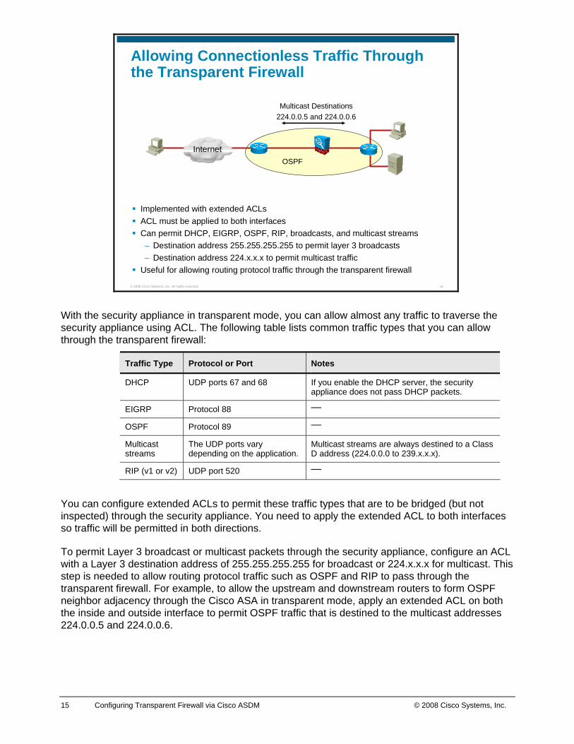
Allowing Connectionless Traffic Through the Transparent Firewall
Implemented with extended ACLsACL must be applied to both interfacesCan permit DHCP, EIGRP, OSPF, RIP, broadcasts, and multicast streams– Destination address 255.255.255.255 to permit layer 3 broadcasts– Destination address 224.x.x.x to permit multicast traffic
Useful for allowing routing protocol traffic through the transparent firewall
With the security appliance in transparent mode, you can allow almost any traffic to traverse the security appliance using ACL. The following table lists common traffic types that you can allow through the transparent firewall:
Traffic Type Protocol or Port Notes
DHCP UDP ports 67 and 68 If you enable the DHCP server, the security appliance does not pass DHCP packets.
EIGRP Protocol 88 —
OSPF Protocol 89 —
Multicast streams
The UDP ports vary depending on the application.
Multicast streams are always destined to a Class D address (224.0.0.0 to 239.x.x.x).
RIP (v1 or v2) UDP port 520 —
You can configure extended ACLs to permit these traffic types that are to be bridged (but not inspected) through the security appliance. You need to apply the extended ACL to both interfaces so traffic will be permitted in both directions.
To permit Layer 3 broadcast or multicast packets through the security appliance, configure an ACL with a Layer 3 destination address of 255.255.255.255 for broadcast or 224.x.x.x for multicast. This step is needed to allow routing protocol traffic such as OSPF and RIP to pass through the transparent firewall. For example, to allow the upstream and downstream routers to form OSPF neighbor adjacency through the Cisco ASA in transparent mode, apply an extended ACL on both the inside and outside interface to permit OSPF traffic that is destined to the multicast addresses 224.0.0.5 and 224.0.0.6.
16 Configuring Transparent Firewall via Cisco ASDM © 2008 Cisco Systems, Inc.
© 2008 Cisco Systems, Inc. All rights reserved. 15
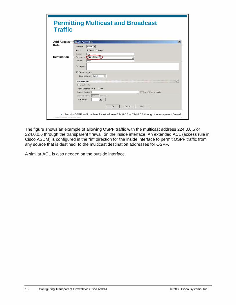
Permitting Multicast and Broadcast Traffic
Permits OSPF traffic with multicast address 224.0.0.5 or 224.0.0.6 through the transparent firewall.
Destination
Add Access Rule
The figure shows an example of allowing OSPF traffic with the multicast address 224.0.0.5 or 224.0.0.6 through the transparent firewall on the inside interface. An extended ACL (access rule in Cisco ASDM) is configured in the “in” direction for the inside interface to permit OSPF traffic from any source that is destined to the multicast destination addresses for OSPF.
A similar ACL is also needed on the outside interface.
17 Configuring Transparent Firewall via Cisco ASDM © 2008 Cisco Systems, Inc.
© 2008 Cisco Systems, Inc. All rights reserved. 16
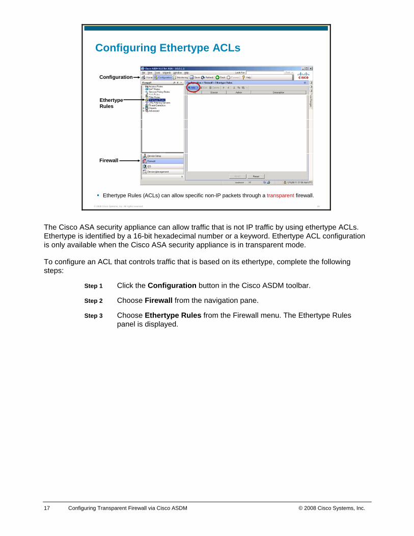
Configuring Ethertype ACLs
Ethertype Rules (ACLs) can allow specific non-IP packets through a transparent firewall.
Firewall
Configuration
EthertypeRules
The Cisco ASA security appliance can allow traffic that is not IP traffic by using ethertype ACLs. Ethertype is identified by a 16-bit hexadecimal number or a keyword. Ethertype ACL configuration is only available when the Cisco ASA security appliance is in transparent mode.
To configure an ACL that controls traffic that is based on its ethertype, complete the following steps:
Step 1 Click the Configuration button in the Cisco ASDM toolbar.
Step 2 Choose Firewall from the navigation pane.
Step 3 Choose Ethertype Rules from the Firewall menu. The Ethertype Rules panel is displayed.
18 Configuring Transparent Firewall via Cisco ASDM © 2008 Cisco Systems, Inc.
© 2008 Cisco Systems, Inc. All rights reserved. 17
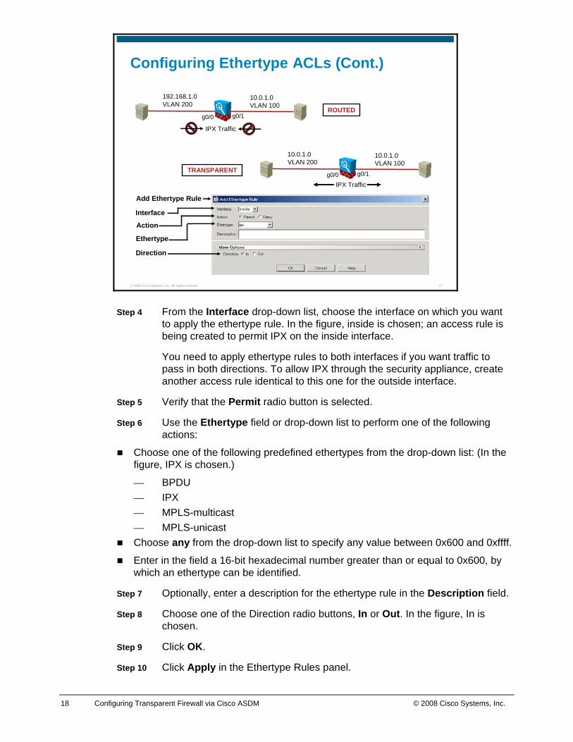
Configuring Ethertype ACLs (Cont.)
Direction
Add Ethertype Rule
Interface
Action
Ethertype
10.0.1.0VLAN 100
192.168.1.0VLAN 200
g0/0 g0/1
10.0.1.0VLAN 100
10.0.1.0VLAN 200
IPX Trafficg0/0 g0/1
ROUTED
TRANSPARENT
IPX Traffic
Step 4 From the Interface drop-down list, choose the interface on which you want to apply the ethertype rule. In the figure, inside is chosen; an access rule is being created to permit IPX on the inside interface.
You need to apply ethertype rules to both interfaces if you want traffic to pass in both directions. To allow IPX through the security appliance, create another access rule identical to this one for the outside interface.
Step 5 Verify that the Permit radio button is selected.
Step 6 Use the Ethertype field or drop-down list to perform one of the following actions:
Choose one of the following predefined ethertypes from the drop-down list: (In the figure, IPX is chosen.)
— BPDU — IPX — MPLS-multicast — MPLS-unicast
Choose any from the drop-down list to specify any value between 0x600 and 0xffff.
Enter in the field a 16-bit hexadecimal number greater than or equal to 0x600, by which an ethertype can be identified.
Step 7 Optionally, enter a description for the ethertype rule in the Description field.
Step 8 Choose one of the Direction radio buttons, In or Out. In the figure, In is chosen.
Step 9 Click OK.
Step 10 Click Apply in the Ethertype Rules panel.
19 Configuring Transparent Firewall via Cisco ASDM © 2008 Cisco Systems, Inc.
© 2008 Cisco Systems, Inc. All rights reserved. 19
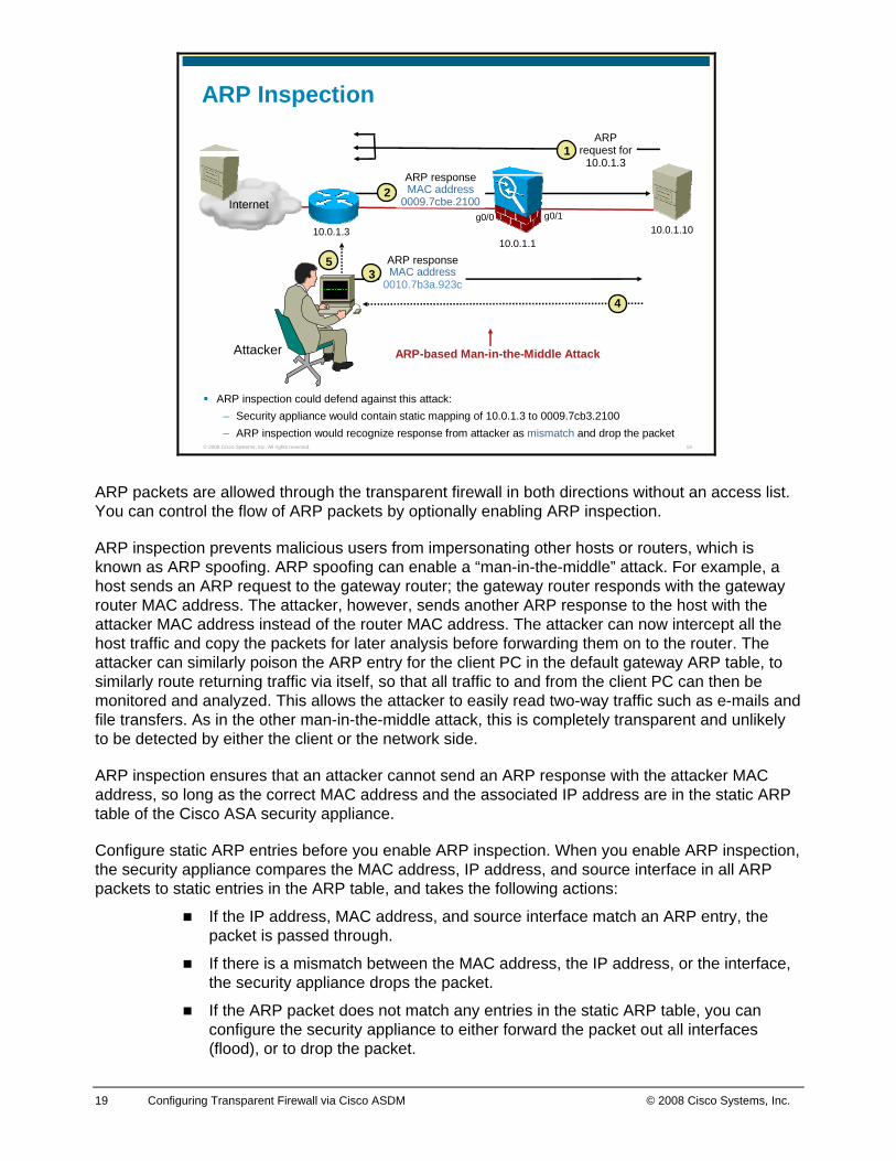
ARP Inspection
ARP inspection could defend against this attack:– Security appliance would contain static mapping of 10.0.1.3 to 0009.7cb3.2100– ARP inspection would recognize response from attacker as mismatch and drop the packet
10.0.1.1010.0.1.1
g0/0 g0/1
10.0.1.3
Attacker
ARP request for
10.0.1.3 ARP response MAC address
0009.7cbe.21002
5
Internet
ARP response MAC address
0010.7b3a.923c3
4
ARP-based Man-in-the-Middle Attack
1
ARP packets are allowed through the transparent firewall in both directions without an access list. You can control the flow of ARP packets by optionally enabling ARP inspection.
ARP inspection prevents malicious users from impersonating other hosts or routers, which is known as ARP spoofing. ARP spoofing can enable a “man-in-the-middle” attack. For example, a host sends an ARP request to the gateway router; the gateway router responds with the gateway router MAC address. The attacker, however, sends another ARP response to the host with the attacker MAC address instead of the router MAC address. The attacker can now intercept all the host traffic and copy the packets for later analysis before forwarding them on to the router. The attacker can similarly poison the ARP entry for the client PC in the default gateway ARP table, to similarly route returning traffic via itself, so that all traffic to and from the client PC can then be monitored and analyzed. This allows the attacker to easily read two-way traffic such as e-mails and file transfers. As in the other man-in-the-middle attack, this is completely transparent and unlikely to be detected by either the client or the network side.
ARP inspection ensures that an attacker cannot send an ARP response with the attacker MAC address, so long as the correct MAC address and the associated IP address are in the static ARP table of the Cisco ASA security appliance.
Configure static ARP entries before you enable ARP inspection. When you enable ARP inspection, the security appliance compares the MAC address, IP address, and source interface in all ARP packets to static entries in the ARP table, and takes the following actions:
If the IP address, MAC address, and source interface match an ARP entry, the packet is passed through.
If there is a mismatch between the MAC address, the IP address, or the interface, the security appliance drops the packet.
If the ARP packet does not match any entries in the static ARP table, you can configure the security appliance to either forward the packet out all interfaces (flood), or to drop the packet.
20 Configuring Transparent Firewall via Cisco ASDM © 2008 Cisco Systems, Inc.
© 2008 Cisco Systems, Inc. All rights reserved. 20
Creating a Static Entry in the ARP Cache
Interface Name
Device Management
Configuration
Advanced
MAC Address
IP AddressARP Static Table
Add
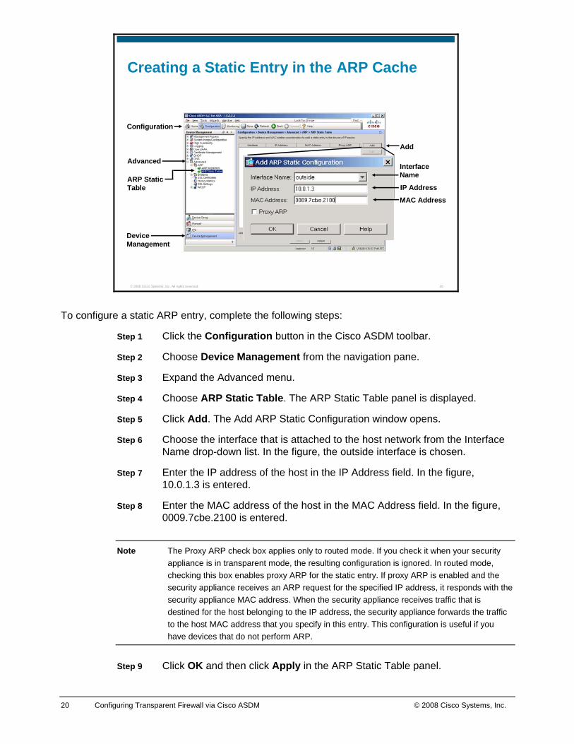
To configure a static ARP entry, complete the following steps:
Step 1 Click the Configuration button in the Cisco ASDM toolbar.
Step 2 Choose Device Management from the navigation pane.
Step 3 Expand the Advanced menu.
Step 4 Choose ARP Static Table. The ARP Static Table panel is displayed.
Step 5 Click Add. The Add ARP Static Configuration window opens.
Step 6 Choose the interface that is attached to the host network from the Interface Name drop-down list. In the figure, the outside interface is chosen.
Step 7 Enter the IP address of the host in the IP Address field. In the figure, 10.0.1.3 is entered.
Step 8 Enter the MAC address of the host in the MAC Address field. In the figure, 0009.7cbe.2100 is entered.
Note The Proxy ARP check box applies only to routed mode. If you check it when your security appliance is in transparent mode, the resulting configuration is ignored. In routed mode, checking this box enables proxy ARP for the static entry. If proxy ARP is enabled and the security appliance receives an ARP request for the specified IP address, it responds with the security appliance MAC address. When the security appliance receives traffic that is destined for the host belonging to the IP address, the security appliance forwards the traffic to the host MAC address that you specify in this entry. This configuration is useful if you have devices that do not perform ARP.
Step 9 Click OK and then click Apply in the ARP Static Table panel.
21 Configuring Transparent Firewall via Cisco ASDM © 2008 Cisco Systems, Inc.
© 2008 Cisco Systems, Inc. All rights reserved. 21
Enabling ARP Inspection
Device Management
Configuration
Advanced
ARP Inspection
Enable ARP Inspection
Edit
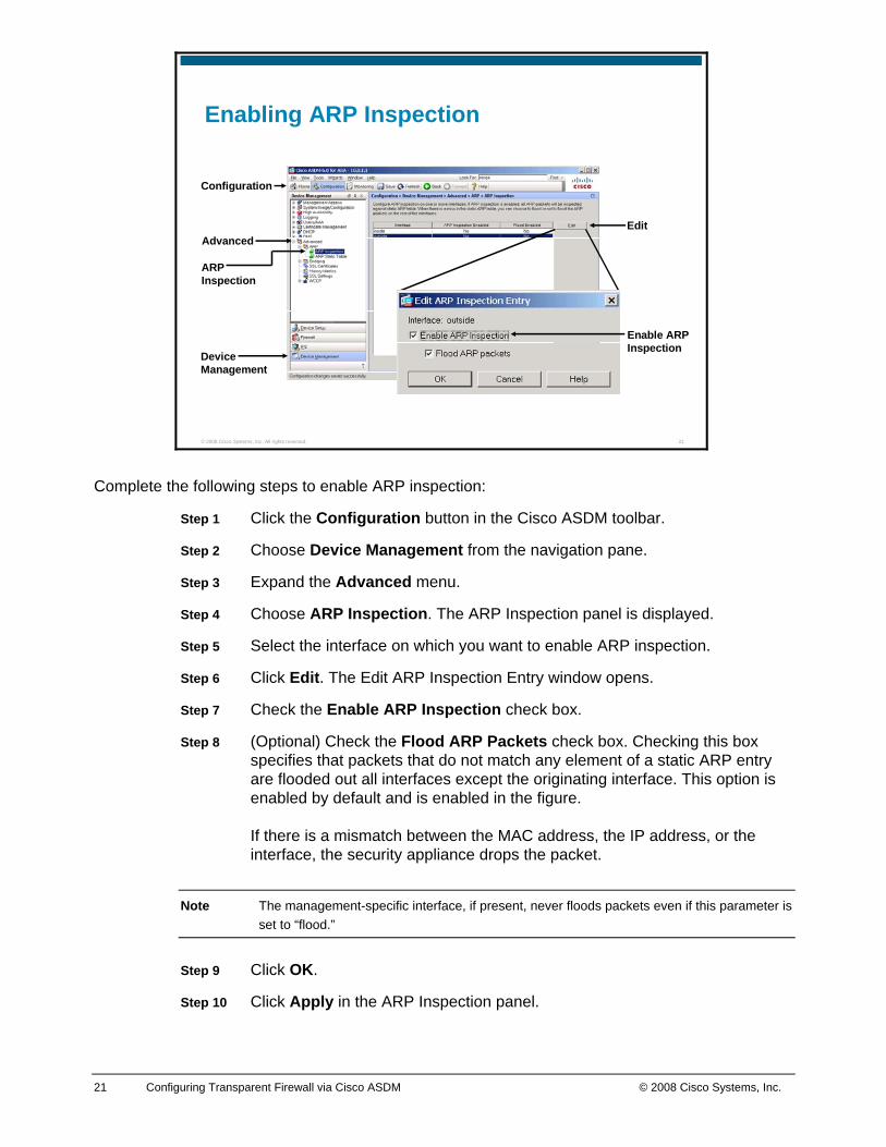
Complete the following steps to enable ARP inspection:
Step 1 Click the Configuration button in the Cisco ASDM toolbar.
Step 2 Choose Device Management from the navigation pane.
Step 3 Expand the Advanced menu.
Step 4 Choose ARP Inspection. The ARP Inspection panel is displayed.
Step 5 Select the interface on which you want to enable ARP inspection.
Step 6 Click Edit. The Edit ARP Inspection Entry window opens.
Step 7 Check the Enable ARP Inspection check box.
Step 8 (Optional) Check the Flood ARP Packets check box. Checking this box specifies that packets that do not match any element of a static ARP entry are flooded out all interfaces except the originating interface. This option is enabled by default and is enabled in the figure. If there is a mismatch between the MAC address, the IP address, or the interface, the security appliance drops the packet.
Note The management-specific interface, if present, never floods packets even if this parameter is set to “flood.”
Step 9 Click OK.
Step 10 Click Apply in the ARP Inspection panel.
22 Configuring Transparent Firewall via Cisco ASDM © 2008 Cisco Systems, Inc.
© 2008 Cisco Systems, Inc. All rights reserved. 22
MAC Address Table
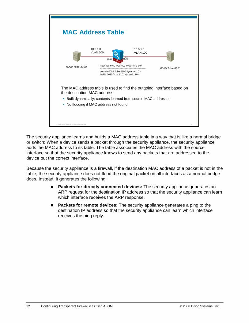
The MAC address table is used to find the outgoing interface based on the destination MAC address.
Built dynamically; contents learned from source MAC addresses No flooding if MAC address not found
10.0.1.0VLAN 100
10.0.1.0VLAN 200
Interface MAC Address Type Time Left--------------------------------------------------------outside 0009.7cbe.2100 dynamic 10 -inside 0010.7cbe.6101 dynamic 10 -
0009.7cbe.2100 0010.7cbe.6101
g0/0 g0/1
The security appliance learns and builds a MAC address table in a way that is like a normal bridge or switch: When a device sends a packet through the security appliance, the security appliance adds the MAC address to its table. The table associates the MAC address with the source interface so that the security appliance knows to send any packets that are addressed to the device out the correct interface.
Because the security appliance is a firewall, if the destination MAC address of a packet is not in the table, the security appliance does not flood the original packet on all interfaces as a normal bridge does. Instead, it generates the following:
Packets for directly connected devices: The security appliance generates an ARP request for the destination IP address so that the security appliance can learn which interface receives the ARP response.
Packets for remote devices: The security appliance generates a ping to the destination IP address so that the security appliance can learn which interface receives the ping reply.
23 Configuring Transparent Firewall via Cisco ASDM © 2008 Cisco Systems, Inc.
© 2008 Cisco Systems, Inc. All rights reserved. 23
Disabling MAC Address Learning
Device Management
Configuration
Advanced
Bridging
MAC Learning
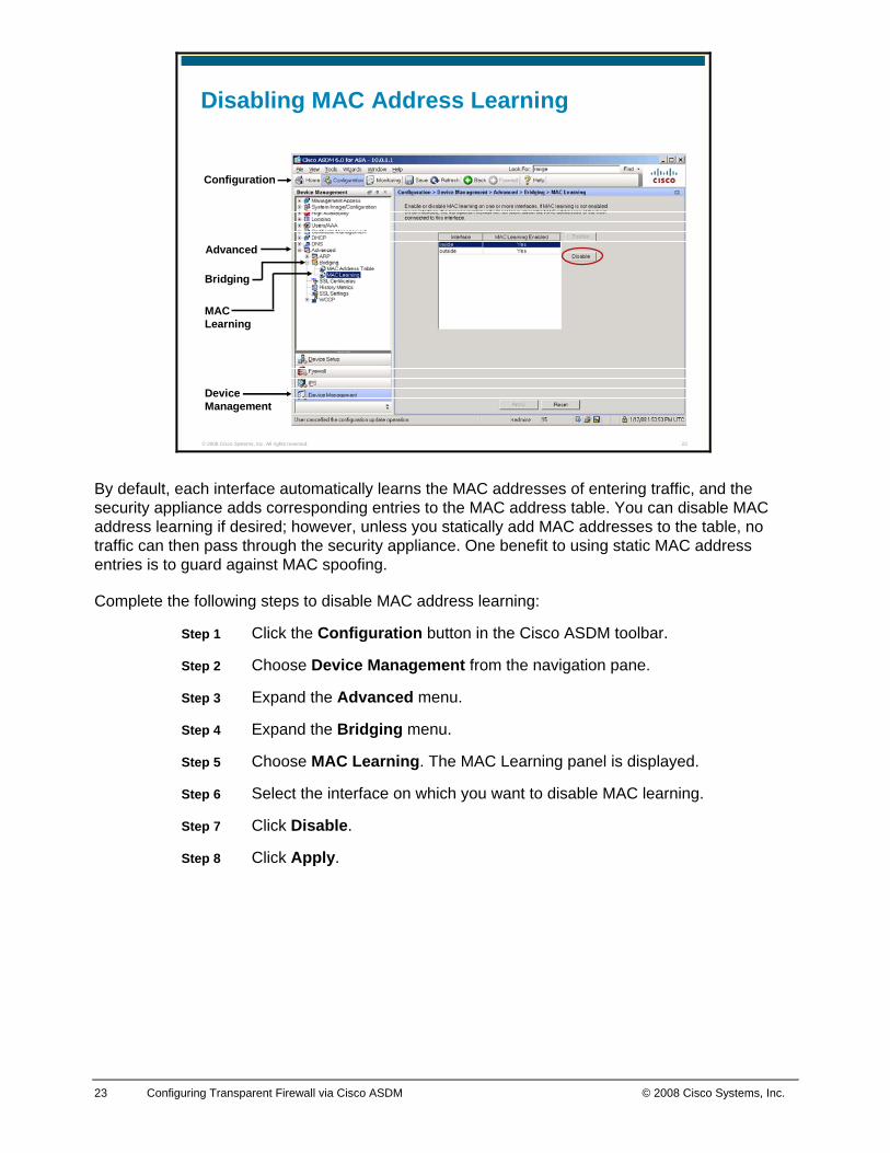
By default, each interface automatically learns the MAC addresses of entering traffic, and the security appliance adds corresponding entries to the MAC address table. You can disable MAC address learning if desired; however, unless you statically add MAC addresses to the table, no traffic can then pass through the security appliance. One benefit to using static MAC address entries is to guard against MAC spoofing.
Complete the following steps to disable MAC address learning:
Step 1 Click the Configuration button in the Cisco ASDM toolbar.
Step 2 Choose Device Management from the navigation pane.
Step 3 Expand the Advanced menu.
Step 4 Expand the Bridging menu.
Step 5 Choose MAC Learning. The MAC Learning panel is displayed.
Step 6 Select the interface on which you want to disable MAC learning.
Step 7 Click Disable.
Step 8 Click Apply.
24 Configuring Transparent Firewall via Cisco ASDM © 2008 Cisco Systems, Inc.
© 2008 Cisco Systems, Inc. All rights reserved. 24
Adding a Static MAC Address
Device Management
Configuration
Add
MAC Address Table
Advanced
BridgingInterface Name
MAC Address
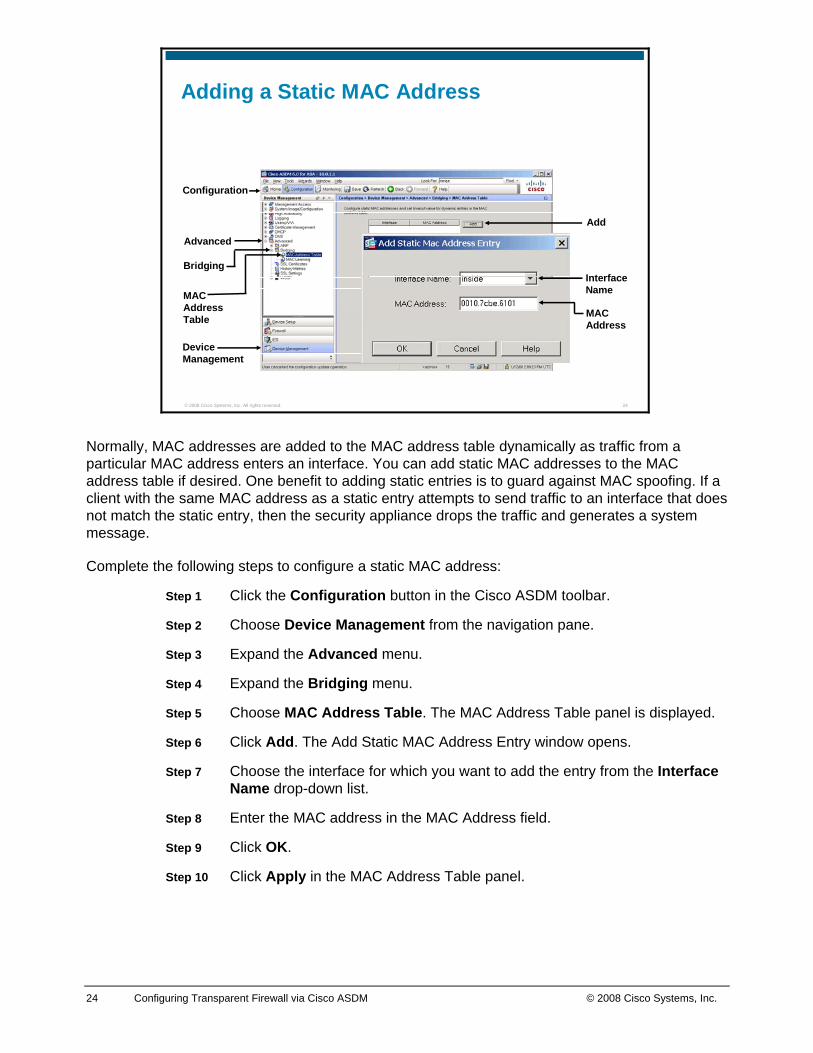
Normally, MAC addresses are added to the MAC address table dynamically as traffic from a particular MAC address enters an interface. You can add static MAC addresses to the MAC address table if desired. One benefit to adding static entries is to guard against MAC spoofing. If a client with the same MAC address as a static entry attempts to send traffic to an interface that does not match the static entry, then the security appliance drops the traffic and generates a system message.
Complete the following steps to configure a static MAC address:
Step 1 Click the Configuration button in the Cisco ASDM toolbar.
Step 2 Choose Device Management from the navigation pane.
Step 3 Expand the Advanced menu.
Step 4 Expand the Bridging menu.
Step 5 Choose MAC Address Table. The MAC Address Table panel is displayed.
Step 6 Click Add. The Add Static MAC Address Entry window opens.
Step 7 Choose the interface for which you want to add the entry from the Interface Name drop-down list.
Step 8 Enter the MAC address in the MAC Address field.
Step 9 Click OK.
Step 10 Click Apply in the MAC Address Table panel.
25 Configuring Transparent Firewall via Cisco ASDM © 2008 Cisco Systems, Inc.
© 2008 Cisco Systems, Inc. All rights reserved. 25
Viewing the MAC Address Table
Interfaces
Monitoring
MAC Address Table
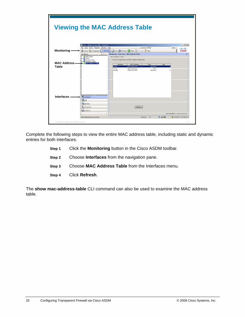
Complete the following steps to view the entire MAC address table, including static and dynamic entries for both interfaces:
Step 1 Click the Monitoring button in the Cisco ASDM toolbar.
Step 2 Choose Interfaces from the navigation pane.
Step 3 Choose MAC Address Table from the Interfaces menu.
Step 4 Click Refresh.
The show mac-address-table CLI command can also be used to examine the MAC address table.
26 Configuring Transparent Firewall via Cisco ASDM © 2008 Cisco Systems, Inc.
© 2008 Cisco Systems, Inc. All rights reserved. 26
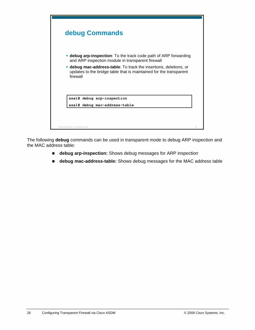
asa1# debug arp-inspection
asa1# debug mac-address-table
debug Commands
debug arp-inspection: To the track code path of ARP forwarding and ARP inspection module in transparent firewalldebug mac-address-table: To track the insertions, deletions, or updates to the bridge table that is maintained for the transparent firewall
The following debug commands can be used in transparent mode to debug ARP inspection and the MAC address table:
debug arp-inspection: Shows debug messages for ARP inspection
debug mac-address-table: Shows debug messages for the MAC address table