Embed Size (px)
Citation preview

Translation of the original
Operating Manual
Tube end forming machine SFO-F-A-A
To avoid injuries and damage read this operating manual thoroughly and attentively. Retain it for further reference.
R01_en

2 / 60 www.stauffconnect.com
Walter Stauffenberg GmbH & Co. KG Im Ehrenfeld 4 58791 Werdohl Germany
Telephone: +49 23 92 916 0 Fax: +49 23 92 916 160
[email protected] www.stauffconnect.com

SFO-F-A-A www.stauffconnect.com 3 / 60
Table of contents
Table of contents 1 Information about the manual ....................................................................... 5
1.1 Target group of the operating manual ...................................................... 5
1.2 Warnings structure .................................................................................... 5
1.3 Instructions structure ................................................................................ 6
1.4 Additional information structure ................................................................ 6
1.5 References structure ................................................................................ 6
2 For your safety ................................................................................................ 7
2.1 General safety instructions ....................................................................... 7
2.2 Intended use ............................................................................................. 8
2.3 Tasks and obligations of the operating company ..................................... 8
2.4 Personnel qualification .............................................................................. 9
2.5 Personal protective equipment ................................................................. 9
2.6 Safety markings ........................................................................................ 9
2.7 Safety devices ........................................................................................ 10
2.8 Securing machine against switching on ................................................. 11
3 Machine description ..................................................................................... 12
3.1 Machine overview ................................................................................... 12
3.2 Technical data ........................................................................................ 13
3.3 Function .................................................................................................. 13
3.4 Tools and product ................................................................................... 14
3.5 Type plate ............................................................................................... 15
3.6 Spare and wear parts ............................................................................. 16
4 Transport and storage .................................................................................. 17
4.1 Safety 17
4.2 Handling .................................................................................................. 17
5 Installation ..................................................................................................... 18
5.1 Safety 18
5.2 Installing the machine ............................................................................. 19
5.3 Attaching supply connections ................................................................. 19
5.4 Establishing readiness for operation ...................................................... 19
6 Operation ....................................................................................................... 20
6.1 Safety 20
6.2 Switching on the machine ....................................................................... 21
6.3 Establishing readiness for operation after emergency stop ................... 26
6.4 Machine set-up ....................................................................................... 27 6.4.1 Setting the language .................................................................... 27 6.4.2 Setting the system properties ...................................................... 29

4 / 60 www.stauffconnect.com
Table of contents
6.5 Setting up a job ....................................................................................... 32 6.5.1 Setting the material ...................................................................... 33 6.5.2 Setting up the tube size ............................................................... 34 6.5.3 Setting up the wall thickness ....................................................... 35 6.5.4 Setting the production quantity .................................................... 36 6.5.5 Inserting/changing tool ................................................................ 36
6.6 Forming tube ends .................................................................................. 42
6.7 Cleaning the machine ............................................................................. 44
6.8 Switching off the machine ....................................................................... 44
7 Troubleshooting ............................................................................................ 45
7.1 Safety 45
7.2 Troubleshooting ...................................................................................... 46
7.3 Faults/error messages ............................................................................ 47 7.3.1 Reshaping path ........................................................................... 47 7.3.2 Target position ............................................................................. 48 7.3.3 Reference run .............................................................................. 48 7.3.4 Parameters .................................................................................. 49 7.3.5 Direction of rotation ..................................................................... 49 7.3.6 Motor protection switch activated ................................................ 50 7.3.7 Tool .............................................................................................. 50 7.3.8 Other faults .................................................................................. 51
8 Maintenance .................................................................................................. 53
8.1 Safety 53
8.2 Inspection and maintenance ................................................................... 53
8.3 Checking the emergency stop ................................................................ 53
9 Decommissioning ......................................................................................... 54
9.1 Safety 54
9.2 Dismantling ............................................................................................. 55
9.3 Disposal .................................................................................................. 55
10 EC Declaration of Conformity ...................................................................... 56
Table of figures .................................................................................................. 57
Key word list ....................................................................................................... 59
SFO-F-A-A www.stauffconnect.com 5 / 60
1 Information about the manual
1 Information about the manual This manual includes important instructions and information on the intended use. Keep the operating manual where it can be accessed by the operating personnel.
1.1 Target group of the operating manual The operating personnel tasked with the following work has to read and observe this operating manual:
• installation
• operation
• malfunction
• maintenance
See personnel qualifications chapter 2.4, p. 9.
1.2 Warnings structure Coloured signal word boxes emphasise the warnings. Always read the full warning text for effective protection against hazards!
The different colours and signal words of the following boxes designate various hazard levels:
Ignoring this warning results in serious or lethal injuries.
Ignoring this warning can result in serious or lethal injuries.
Ignoring this warning can result in minor or moderately severe injuries.
Ignoring this warning can result in property damage.
IMPORTANT
CAUTION
WARNING
DANGER
6 / 60 www.stauffconnect.com
1 Information about the manual
Warnings are always structured in the same manner. They include the signal word, hazard type and source, consequences of ignoring them and steps to ward off/avoid hazards.
Example:
Hazard of shearing off and crushing fingers
► Ensure before startup that all safety equipment is properly installed and in working order!
► Ensure that your fingers are not in the forming area when carrying out the machine functions!
1.3 Instructions structure Instructions are a direct request to carry out a task. They are structured in line with the operation involved. Always carry out the operating steps in the prescribed sequence.
The instructions are structured as follows and marked with the appropriate symbols:
Objective of the instruction
1. Operating step
✓ Effect of the operating step to check if the step has been executed correctly.
2. Additional operating step
Result of the overall instruction
1.4 Additional information structure
1.5 References structure References are shown in this manual as follows:
Example:
“… only operate the machine as intended chapter 2.2, p. 8.“
Text marked with an info symbol provide additional information and tips.
WARNING

SFO-F-A-A www.stauffconnect.com 7 / 60
2 For your safety
2 For your safety To avoid accidents and injuries, …
• observe all general and specific safety instructions and the warnings in this manual
• observe hazard and prohibitory signs
• follow the accident prevention regulations and directives applicable at the place of operation
• observe all inspection and maintenance intervals
• only operate the machine as intended
2.1 General safety instructions Safety instructions help you in avoiding injuries and damage. Ensure that you have read and understood all the safety instructions in this operating manual.
Safe working entails doing more that just reading the general safety instructions in this chapter. Also read and observe the specific safety instructions in all chapters affecting your work. Also observe information in the referenced product documents.
The following general safety instructions apply to all work undertaken on the machine:
• Observe the valid national and international health and safety regulations.
• Only operate the machine …
– in a technically satisfactory condition
– taking into account safety and hazards
– according to the intended use
– in compliance with this operating manual and
– with all protective devices unchanged, complete, correctly installed and functioning
• Wear the appropriate personal protective equipment for all work on the
machine chapter 2.5, p. 9.
• Observe all safety markings attached to the machine chapter 2.6, p. 9.
• Work on electrical equipment may only be carried out by Walter Stauffenberg GmbH & Co. KG.
• Immediately rectify faults which affect your safety and the reliable operation of the machine. Take the machine out of service until the fault is rectified.
• Components – except tools – may only be replaced by Walter Stauffenberg GmbH & Co. KG.
8 / 60 www.stauffconnect.com
2 For your safety
• Keep away from moving parts. Wear close fitting clothes. Tie long hair back to prevent it from being drawn into the machine. Remove any rings and necklaces before the work.
• Be aware of the presence of residual energies in mechanical, hydraulic and electrical components.
2.2 Intended use The tube end forming machine is designed exclusively for machine forming of seamless precision steel tubes according to EN 10305-1 with an outer tube diameter between 6 mm and 42 mm.
The machine is used together with internal tube support, tube shaper and shaping jaws which are specially designed for machine forming of tube ends.
The machine may only be used within the specifications prescribed in the
chapter Technical Data chapter 3.2, p. 13 and in compliance with the
maintenance instructions and other instructions in this manual and in the referenced documents.
No changes, attachments or conversions may be carried out without consultation with the manufacturer. Such modifications could limit the operating safety of the machine and are considered to be a violation of intended use.
Any use other than the intended use is not permitted.
2.3 Tasks and obligations of the operating company In addition to the instructions and information in this operating manual, the general, statutory and other mandatory regulations on accident prevention and environmental protection also have to be observed.
To ensure safe machine operation, the operating company has to at least …
• ensure that the machine is only operated as intended, in proper condition, with all safety devices fully installed and without damage
• establish the area of application and prepare the corresponding operating instructions
• always keep the safety markings attached to the machined complete and legible
• make the operating manual available in a complete and legible form at the operating location of the machine at all times
• instruct the personnel working on the machine in the corresponding tasks on the machine
• acquire the regulations applicable to the machine in their most recent version and to familiarise personnel working on the machine with these
SFO-F-A-A www.stauffconnect.com 9 / 60
2 For your safety
• provide the personnel operating the machine with the required personal protective equipment
• carry out a safety briefing on the machine
• ensure sufficient ventilation and lighting of the work area
2.4 Personnel qualification Any work on the machine may only be carried out by qualified and authorised personnel. Personnel instructed, trained or briefed in the work involved is considered to be qualified. This has to be backed up by appropriate certificates and records.
A distinction is made in this manual between:
• Operating personnel - those who have been demonstrably briefed in operation and function of the machine. They input the data required for the operation and carry out the required operating steps to operate the machine. They are also responsible for simple maintenance work and fault rectification
as described in chapter 7, p. 45 and chapter 8, p. 53 .
• Personnel learning on the job may only work on the machine under the constant supervision of personnel qualified for this work.
2.5 Personal protective equipment The following personal protective equipment is mandatory for those working on the machine:
2.6 Safety markings The following safety markings are attached to the machine in a clearly visible and legible manner:
Warning – hand injuries!
Warning – dangerous electrical voltage!
Wear safety boots!
Wear close fitting work clothes!

10 / 60 www.stauffconnect.com
2 For your safety
2.7 Safety devices Safety devices protect operating personnel against hazards.
Before each startup of the machine, all safety devices have to be fitted correctly and in working order.
Safety devices may only be removed when the machine has stopped and is protected against being accidentally switched on again by means of a padlock or a similarly suitable measure.
The following safety devices are attached to the machine or have to be fitted by the operating company:
Electrical main switch The electrical main switch is located at the front of the machine. The electrical main switch de-energizes the entire machine (position: 0). The electrical main switch is secured against
being accidentally switched on again
chapter 2.8, p. 11.
Emergency stop button Pressing the emergency stop button triggers an emergency stop resulting in all machine movements being stopped. To start the machine up again, the activated emergency stop has to be released
chapter 6.3, p. 26.
1: Safety devices
1 Electrical main switch
2 Emergency stop button
SFO-F-A-A www.stauffconnect.com 11 / 60
2 For your safety
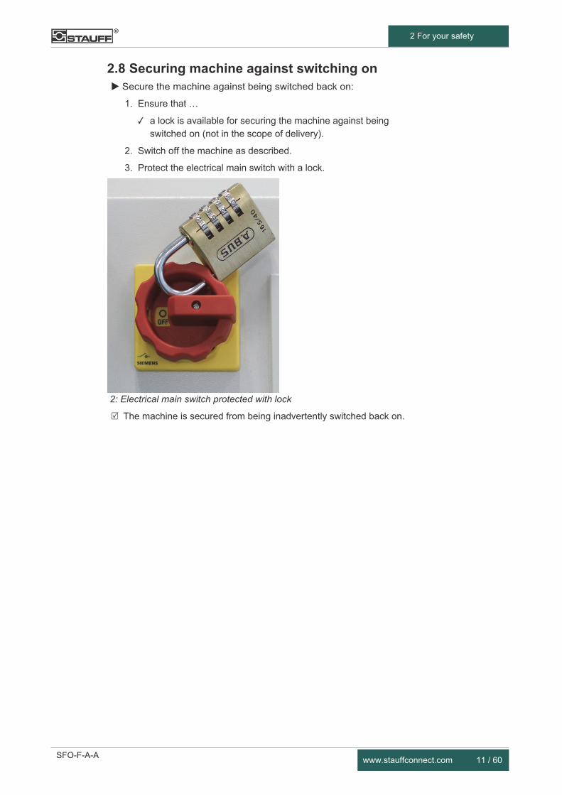
2.8 Securing machine against switching on Secure the machine against being switched back on:
1. Ensure that …
✓ a lock is available for securing the machine against being switched on (not in the scope of delivery).
2. Switch off the machine as described.
3. Protect the electrical main switch with a lock.
2: Electrical main switch protected with lock
The machine is secured from being inadvertently switched back on.
12 / 60 www.stauffconnect.com
3 Machine description
3 Machine description
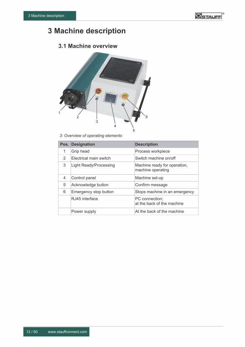
3.1 Machine overview
3: Overview of operating elements
Pos. Designation Description
1 Grip head Process workpiece
2 Electrical main switch Switch machine on/off
3 Light Ready/Processing Machine ready for operation, machine operating
4 Control panel Machine set-up
5 Acknowledge button Confirm message
6 Emergency stop button Stops machine in an emergency
RJ45 interface PC connection; at the back of the machine
Power supply At the back of the machine
SFO-F-A-A www.stauffconnect.com 13 / 60
3 Machine description
3.2 Technical data
General data
Dimensions (W x D x H) 850 mm x 890 mm x 330 mm
Weight incl. oil: 210 kg
Electrical power
Electrical connection: 400 V / AC3 / 50 Hz 460 V / AC3 / 60 Hz
Current consumption: 2.55 / 2.5 A
Hydraulic energy
Oil capacity: 6.1 litres
Max. operating pressure: 700 bar
Installation requirements
Ambient temperature: Dry between 15 °C and 35 °C
Position Horizontal
Sound pressure level
in acc. with EN ISO 11202:2009: 68 dB(A)
3.3 Function The machine forms tube ends to make them suitable for use with fittings according to ISO 8434-1. Seamless precision steel tubes according to EN 10305-1 with an outer tube diameter between 6 mm and 42 mm can be used.
The machine is used together with internal tube support, tube shaper and shaping jaws which are specially designed for machine forming of tube ends.
14 / 60 www.stauffconnect.com
3 Machine description
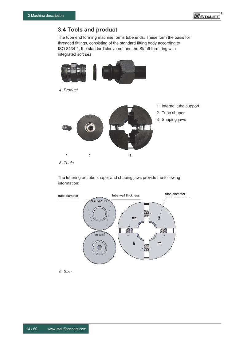
3.4 Tools and product The tube end forming machine forms tube ends. These form the basis for threaded fittings, consisting of the standard fitting body according to ISO 8434-1, the standard sleeve nut and the Stauff form ring with integrated soft seal.
4: Product
5: Tools
1 Internal tube support
2 Tube shaper
3 Shaping jaws
The lettering on tube shaper and shaping jaws provide the following information:
6: Size
tube diameter tube wall thickness tube diameter
SFO-F-A-A www.stauffconnect.com 15 / 60
3 Machine description
Damage to the tool from incorrect internal tube support
► Tube shapers with internal hole are designed for forming with internal tube supports. Ensure to always use the correct internal tube support for the wall thickness selected as otherwise the tool can be damaged!
Please refer to the Stauff product catalogue for additional information on selection of the size.
3.5 Type plate The type plate is located on the side of the machine.
7: Type plate
IMPORTANT

16 / 60 www.stauffconnect.com
3 Machine description
3.6 Spare and wear parts
Replacing components
Machine damage, malfunctions, faults
► Any work for which the machine has to be opened may only be performed by Walter Stauffenberg GmbH & Co. KG!
► Maintenance work may only be carried out by authorised setup and maintenance personnel!
► Only use suitable tools in proper condition!
► Only replace components with original parts or parts authorised by the manufacturer!
Lists of authorised spare parts and wear parts can be obtained from Walter Stauffenberg GmbH & Co. KG.
IMPORTANT

SFO-F-A-A www.stauffconnect.com 17 / 60
4 Transport and storage
4 Transport and storage
4.1 Safety
Lifting loads
Serious or lethal injuries from falling/swaying loads
► Before raising the load, secure all moving components!
► Only use undamaged lifting equipment which is permitted for the weight of the load to be lifted!
► Only attach load attachment gear to the indicated attachment points!
► Never leave loads hanging in the lifting devices without supervision!
► Never stand underneath suspended loads!
Transporting the machine
Serious or lethal injuries from tilting or slipping loads
► Before transporting the machine, fix all its moving components!
► Secure the machine against overturning or slipping out of position during transport!
► Only use transport vehicles suitable for the weight of the machine!
4.2 Handling
Note the following during transport:
• The attachment points are the side bars/grips of the machine.
• Keep the machine horizontal during any transport. Note that the centre of gravity is in the installation area.
• Transport may only be carried out by an authorised specialist company or by qualified personnel.
• Dispose of all packaging material in a proper and environmentally compatible manner after transport.
Information on dimensions and weight can be found in chapter 3.2, p. 13.
WARNING
WARNING

18 / 60 www.stauffconnect.com
5 Installation
5 Installation
5.1 Safety
Lifting loads
Serious or lethal injuries from falling/swaying loads
► Before raising the load, secure all moving components!
► Only use undamaged lifting equipment which is permitted for the weight of the load to be lifted!
► Only attach load attachment gear to the indicated attachment points!
► Never leave loads hanging in the lifting devices without supervision!
► Never stand underneath suspended loads!
Carrying out installation work
Incorrect installation leads to serious/lethal injuries or machine damage
► Installation work may only be carried out by authorised specialist personnel!
► Only use suitable tools in proper condition!
► Wear your personal protective equipment for all work!
Connecting the machine to the power supply
Serious or lethal injuries from dangerous electrical voltage
► Work on electrical equipment may only be carried out by qualified electricians!
► Work on live parts is only permitted under supervision of a second person!
Hazard of shearing off and crushing fingers
► Ensure before startup that all safety equipment is properly installed and in working order!
► Ensure that your fingers are not in the forming area when carrying out the machine functions!
WARNING
WARNING
WARNING
WARNING
SFO-F-A-A www.stauffconnect.com 19 / 60
5 Installation
5.2 Installing the machine The machine is assembled ready for operation by the manufacturer and supplied with the control unit set up.
Control unit updates can be requested from the manufacturer.
Note the following before the installation:
• Set up the machine on a sturdy base.
• Set up the machine so there is space to work around it.
• Inspect the machine for any signs of damage.
5.3 Attaching supply connections Attach the machine to the following supply connections:
• power supply
5.4 Establishing readiness for operation A visual check and function test has to be carried out on the machine before startup. It has to be ensured that …
• all parts are mounted correctly, show no damage and are in full working order
• all outer connections are installed and fully tightened
• all safety devices are functioning chapter 8.3, p. 53.
20 / 60 www.stauffconnect.com
6
6 Operation The ensure safe operation, the machine may only be used in accordance
with the intended use chapter 2.2, p. 8.
6.1 Safety
Hazard of shearing off and crushing fingers
► Ensure before startup that all safety equipment is properly installed and in working order!
► Ensure that your fingers are not in the forming area when carrying out the machine functions!
Hazard from incorrect operation and operator errors
► Operating personnel have to have read and understood the operating manual!
► Operating personnel have to have received training and instruction in the handling of the machine!
Danger from the operator meddling with the safety equipment
► Before startup of the machine, ensure that all safety devices are installed correctly and are functioning!
CAUTION
CAUTION
WARNING
SFO-F-A-A www.stauffconnect.com 21 / 60
6 Operation
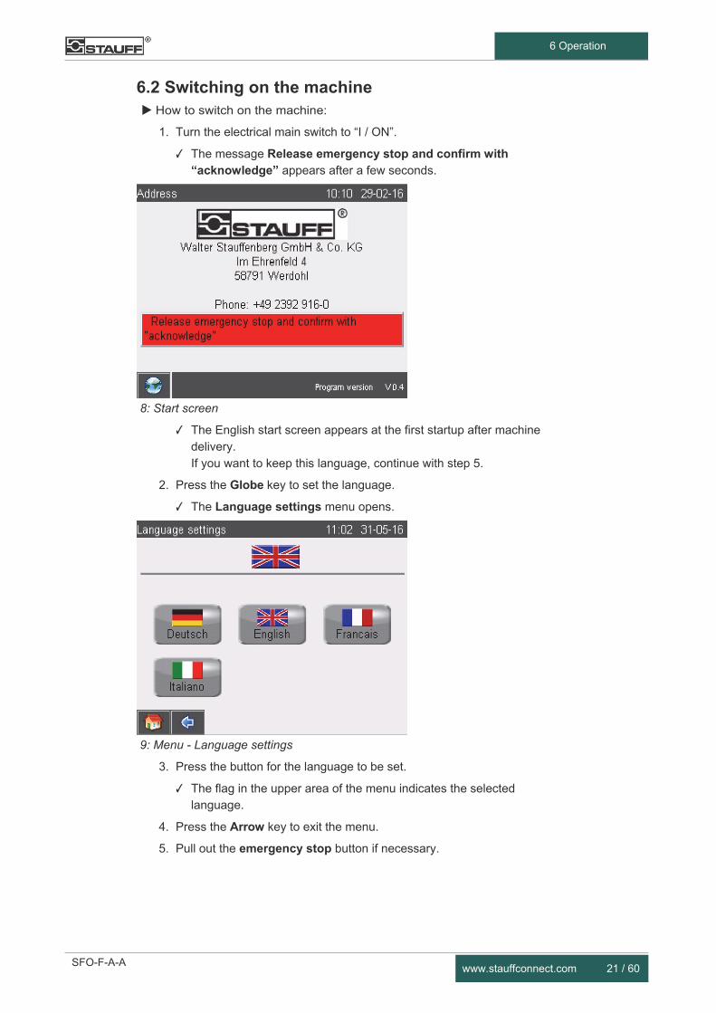
6.2 Switching on the machine How to switch on the machine:
1. Turn the electrical main switch to “I / ON”.
✓ The message Release emergency stop and confirm with “acknowledge” appears after a few seconds.
8: Start screen
✓ The English start screen appears at the first startup after machine delivery. If you want to keep this language, continue with step 5.
2. Press the Globe key to set the language.
✓ The Language settings menu opens.
9: Menu - Language settings
3. Press the button for the language to be set.
✓ The flag in the upper area of the menu indicates the selected language.
4. Press the Arrow key to exit the menu.
5. Pull out the emergency stop button if necessary.

22 / 60 www.stauffconnect.com
6 Operation
6. Press the Acknowledge button.
✓ The Reference run/Material menu opens.
10: Menu - Reference run/Material
✓ The Ready/Process running lamp flashes.
The machine is ready for operation.
Check whether a tool is installed. If not, set up a new job chapter 6.5, p. 32.
If a tool is already installed, you can continue with the existing job. Start the reference run as described on the following pages.
How to carry out the reference run without tool change:
Press the Reference run button.
✓ The message Start reference run opens.
Damage to the machine from incorrectly executed reference run
► Only carry out the reference run without a tube! Do not place a tube into the tool until the reference run is completed.
IMPORTANT

SFO-F-A-A www.stauffconnect.com 23 / 60
6 Operation
11: Start reference run
1. Simultaneously press and hold the Reference run and Acknowledge buttons.
✓ The reference run is started.
✓ The Ready/Process runs lamp lights up continuously.
✓ The message Release grip head opens.
12: Releasing the grip head
13: Pulling out the grip head

24 / 60 www.stauffconnect.com
6 Operation
2. Rotate the grip head to the left on the provided handles and pull it out using both hands
14: Releasing and pulling out the grip head
✓ The grip head is released and opened.
3. Check tool and remove any contaminations.
Damage to the machine from objects in the forming area
► Before starting the reference run, remove tools and other objects which are not required for the reference run!
✓ The message Insert and lock grip head opens.
15: Inserting and locking grip head
IMPORTANT

SFO-F-A-A www.stauffconnect.com 25 / 60
6 Operation
4. Insert the grip head with both hands and turn to the right.
✓ The grip head is locked.
✓ The message To continue reference run, push and hold “reference run” and “acknowledge”! is displayed.
16: Start reference run
5. Simultaneously press and hold the Reference run and Acknowledge buttons.
✓ The reference run is started.
✓ The Start reshaping process menu opens after the reference run is complete.
17: Start reshaping process
✓ The Ready/Process running lamp flashes.
The machine is ready for operation.
26 / 60 www.stauffconnect.com
6 Operation
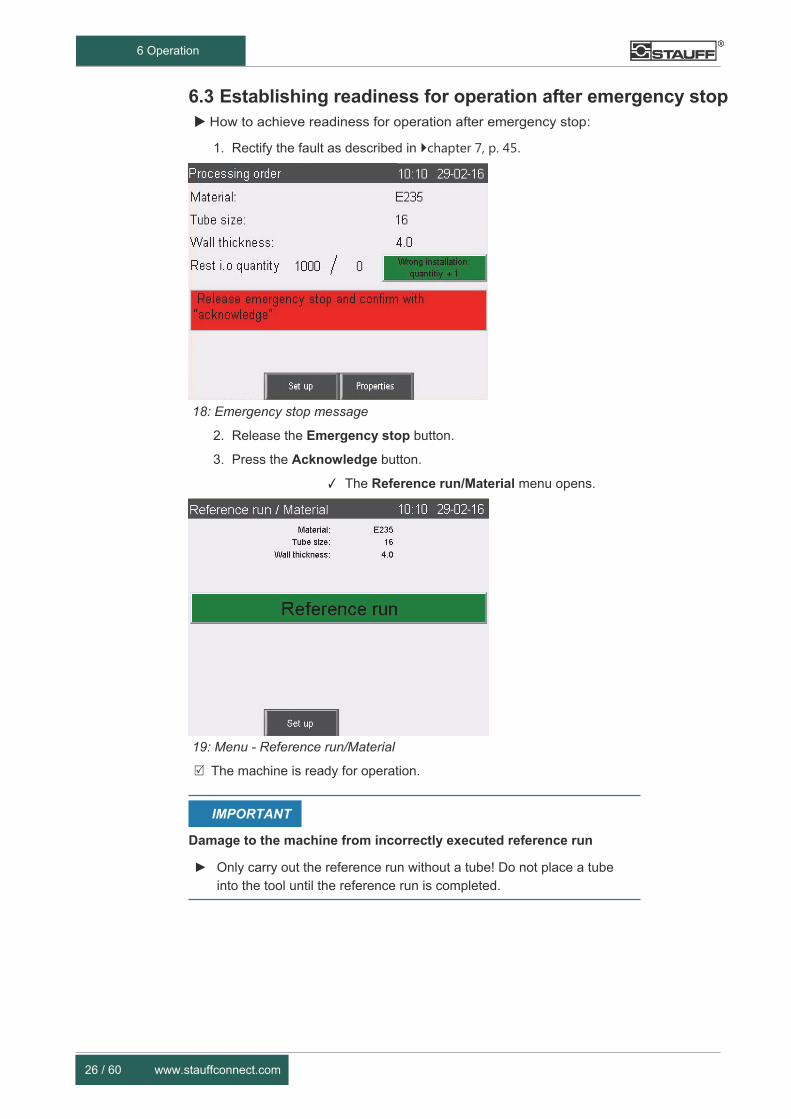
6.3 Establishing readiness for operation after emergency stop How to achieve readiness for operation after emergency stop:
1. Rectify the fault as described in chapter 7, p. 45.
18: Emergency stop message
2. Release the Emergency stop button.
3. Press the Acknowledge button.
✓ The Reference run/Material menu opens.
19: Menu - Reference run/Material
The machine is ready for operation.
Damage to the machine from incorrectly executed reference run
► Only carry out the reference run without a tube! Do not place a tube into the tool until the reference run is completed.
IMPORTANT

SFO-F-A-A www.stauffconnect.com 27 / 60
6 Operation
6.4 Machine set-up
6.4.1 Setting the language
How to set the language: 1. In the menu Processing order, press the Properties button.
20: Menu - Processing order
✓ The Properties Level menu opens.
21: Menu - Properties Level
2. In the menu Properties Level, press the Languages button.
✓ The Language settings menu opens.

28 / 60 www.stauffconnect.com
6 Operation
22: Menu - Languages settings
3. Press the button for the language to be set.
✓ The flag in the upper area of the menu indicates the selected language. Press the Arrow key to exit the menu.
The language is now set.
SFO-F-A-A www.stauffconnect.com 29 / 60
6 Operation
6.4.2 Setting the system properties
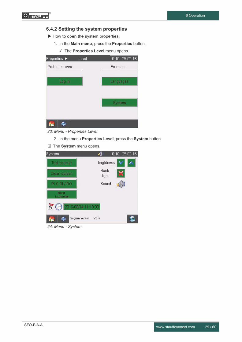
How to open the system properties:
1. In the Main menu, press the Properties button.
✓ The Properties Level menu opens.
23: Menu - Properties Level
2. In the menu Properties Level, press the System button.
The System menu opens.
24: Menu - System

30 / 60 www.stauffconnect.com
6 Operation
How to set date and time:
1. Press the date/time display and enter the desired data.
25: Menu - Input pad for date and time
2. Confirm entry by pressing the green tick.
✓ The input pad for date/time opens.
The set data are displayed.
How to obtain information on the quantity for each tool size:
Press the Tool counter button.
26: Tool counter The quantities for each tool size are displayed. Use the arrow buttons to scroll.
How to switch off the control panel for cleaning:
Press the Clean screen button.
The control panel switches itself off for 10 seconds.
SFO-F-A-A www.stauffconnect.com 31 / 60
6 Operation
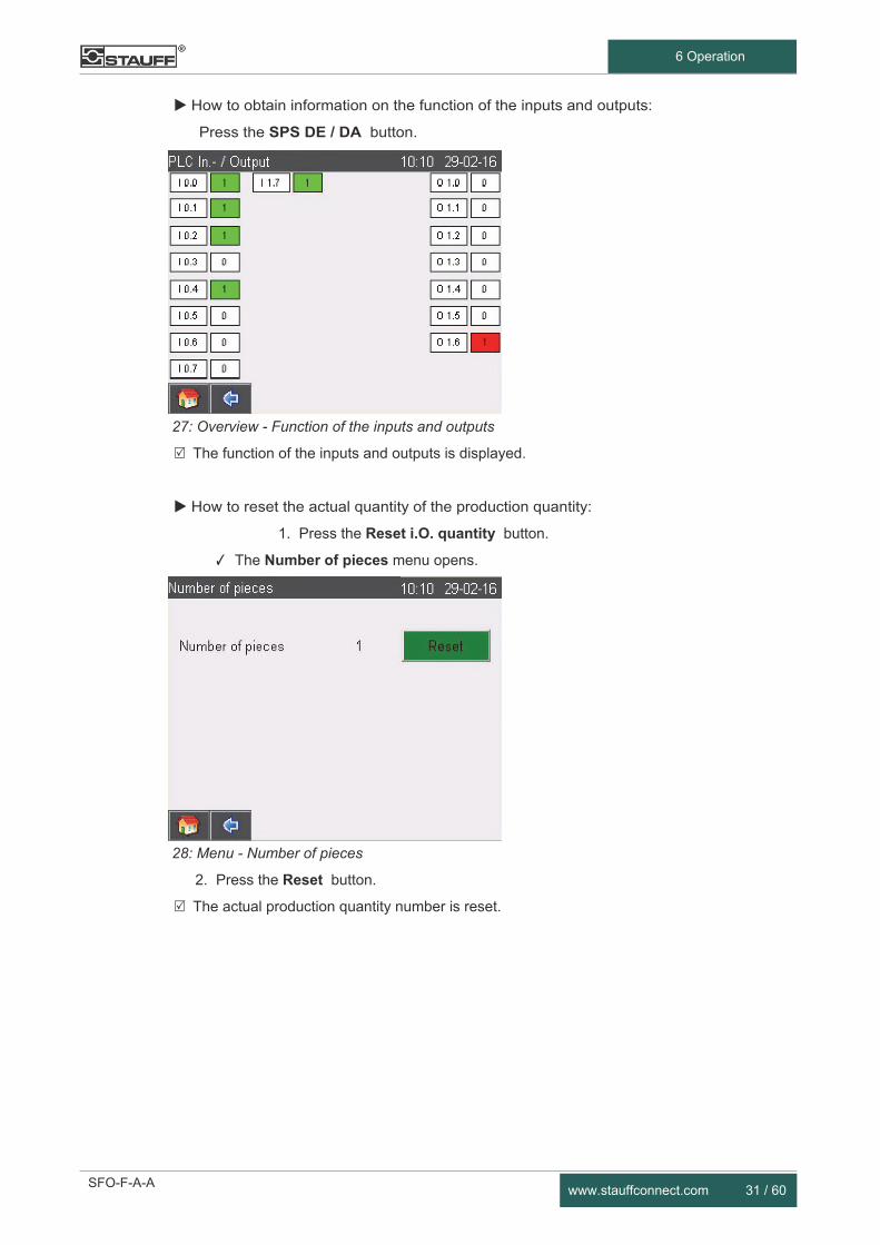
How to obtain information on the function of the inputs and outputs:
Press the SPS DE / DA button.
27: Overview - Function of the inputs and outputs
The function of the inputs and outputs is displayed.
How to reset the actual quantity of the production quantity:
1. Press the Reset i.O. quantity button.
✓ The Number of pieces menu opens.
28: Menu - Number of pieces
2. Press the Reset button.
The actual production quantity number is reset.

32 / 60 www.stauffconnect.com
6 Operation
6.5 Setting up a job How to set up the job:
1. In the Processing order menu, press the Set up button.
29: Menu - Processing order
✓ The Set up order menu opens.
30: Menu - Set up order
2. Carry out the following steps in the order indicated:
3. Set material chapter 6.5.1, p. 33.
4. Set tube size chapter 6.5.2, p. 34.
5. Set wall thickness chapter 6.5.3, p. 35.
6. Set production quantity chapter 6.5.4, p. 36.
7. Insert/change tool chapter 6.5.5, p. 36.

SFO-F-A-A www.stauffconnect.com 33 / 60
6 Operation
6.5.1 Setting the material
How to set the material:
1. In the Set up order menu, press the Material button.
✓ The Set up material menu opens.
31: Menu - Set up material
2. Select the material and press the corresponding button.
3. Confirm the selection with the Confirm button.
✓ The Set up order menu opens.
The selected material is displayed.
32: Menu - Set up order

34 / 60 www.stauffconnect.com
6 Operation
6.5.2 Setting up the tube size
How to set up the tube size: 1. In Set up order menu, press the Tube size button.
✓ The Set up tube size menu opens.
33: Menu - Set up tube size
2. Press the button for the desired tube size.
The menu only displays the tube sizes which can be combined with the selected material. If the required tube size is not displayed, change the set parameters or contact Walter Stauffenberg GmbH & Co. KG.
3. Confirm the selection with the Confirm button.
✓ The Set up order menu opens.
The selected tube size is displayed.
34: Menu - Set up order

SFO-F-A-A www.stauffconnect.com 35 / 60
6 Operation
6.5.3 Setting up the wall thickness
How to set up the wall thickness: 1. In Set up wall thickness menu, press the Wall thickness button.
✓ The Set up wall thickness menu opens.
35: Menu - Set up wall thickness
2. Press the button for the desired wall thickness.
The menu only displays the wall thicknesses which can be combined with the selected tube size. If the required wall thickness is not displayed, change the set parameters or contact Walter Stauffenberg GmbH & Co. KG.
3. Confirm the selection with the Confirm button.
✓ The Set up order menu opens.
The selected wall thickness is displayed.
36 / 60 www.stauffconnect.com
6 Operation
6.5.4 Setting the production quantity
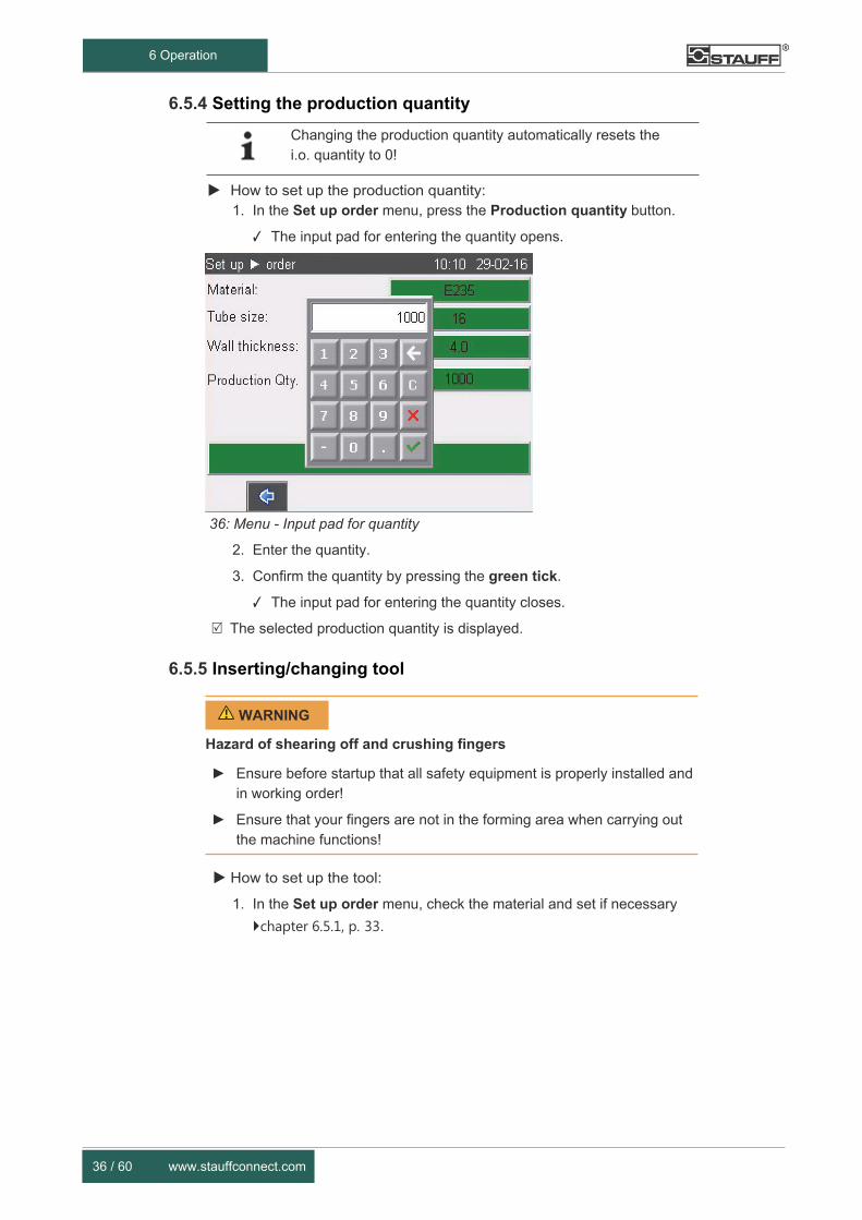
How to set up the production quantity: 1. In the Set up order menu, press the Production quantity button.
✓ The input pad for entering the quantity opens.
36: Menu - Input pad for quantity
2. Enter the quantity.
3. Confirm the quantity by pressing the green tick.
✓ The input pad for entering the quantity closes.
The selected production quantity is displayed.
6.5.5 Inserting/changing tool
Hazard of shearing off and crushing fingers
► Ensure before startup that all safety equipment is properly installed and in working order!
► Ensure that your fingers are not in the forming area when carrying out the machine functions!
How to set up the tool:
1. In the Set up order menu, check the material and set if necessary
chapter 6.5.1, p. 33.
WARNING
Changing the production quantity automatically resets the i.o. quantity to 0!

SFO-F-A-A www.stauffconnect.com 37 / 60
6 Operation
37: Menu - Set up order
2. Confirm the selection with the Confirm button.
✓ The Tool change menu opens.
38: Checking the tool
3. Rotate the grip head to the left on the provided handles, pull it out and swivel it out.
39: Releasing and pulling out the grip head
38 / 60 www.stauffconnect.com
6 Operation
✓ The grip head is released and opened.
✓ The forming cylinder moves out.
Damage to the machine from objects in the forming area
► Before starting the forming process, remove tools and other objects which are not required for forming!
4. Check the forming area and remove any contaminations.
Damage to the machine from different tool sizes.
► Ensure to use the same sizes for the tube shapers, the shaping jaws and the internal tube support. The use of different tool sizes can result in damage to tools and machine!
5. Select the tube shaper, the shaping jaws and possibly the internal tube support according to the set size.
Damage to the machine from worn tools
► Ensure that the tools are in perfect technical condition. The use of worn tools can result in damage to the machine!
6. Check the tools for technically perfect condition.
Damage to the tool from incorrect internal tube support
► Tube shapers with internal hole are designed for forming with internal tube supports. Ensure to always use the correct internal tube support for the wall thickness selected as otherwise the tool can be damaged!
7. If an internal tube support is required, screw it firmly into the tube shaper.
IMPORTANT
IMPORTANT
IMPORTANT
IMPORTANT
SFO-F-A-A www.stauffconnect.com 39 / 60
6 Operation
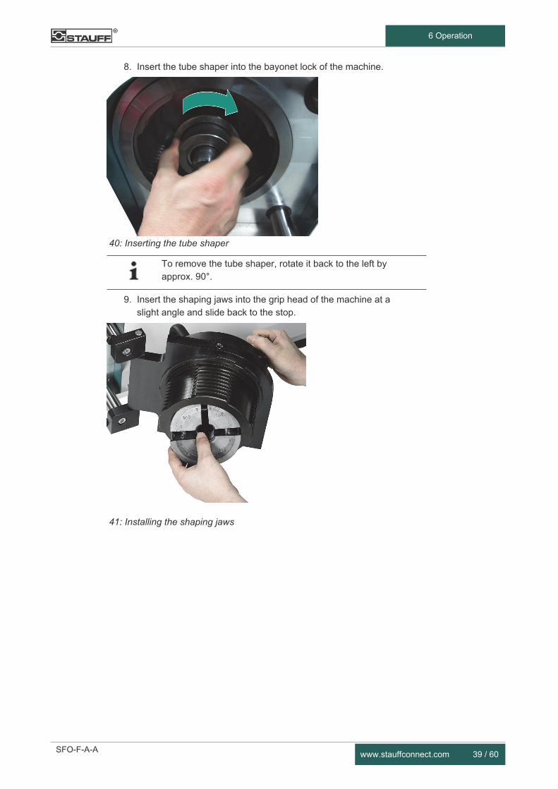
8. Insert the tube shaper into the bayonet lock of the machine.
40: Inserting the tube shaper
9. Insert the shaping jaws into the grip head of the machine at a slight angle and slide back to the stop.
41: Installing the shaping jaws
To remove the tube shaper, rotate it back to the left by approx. 90°.
40 / 60 www.stauffconnect.com
6 Operation
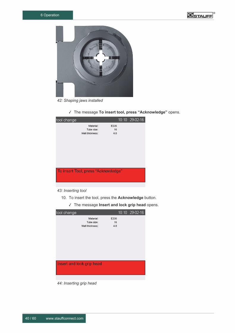
42: Shaping jaws installed
✓ The message To insert tool, press “Acknowledge” opens.
43: Inserting tool
10. To insert the tool, press the Acknowledge button.
✓ The message Insert and lock grip head opens.
44: Inserting grip head

SFO-F-A-A www.stauffconnect.com 41 / 60
6 Operation
11. Swivel the grip head to a straight position, push in with both hands and turn to the right.
✓ The grip head is locked.
✓ The Reference run menu opens.
Damage to the machine from incorrectly executed reference run
► Only carry out the reference run without a tube! Do not place a tube into the tool until the reference run is completed.
45: Start reference run
Simultaneously press and hold the Reference run and Acknowledge buttons.
✓ The reference run is started.
✓ The Ready/Process runs lamp lights up continuously.
✓ The Processing order menu opens after the reference run is complete.
✓ The Ready/Process running lamp flashes.
46: Menu - Processing order
The machine is ready for operation.
IMPORTANT

42 / 60 www.stauffconnect.com
6 Operation
6.6 Forming tube ends
Hazard of shearing off and crushing fingers
► Ensure before startup that all safety equipment is properly installed and in working order!
► Ensure that your fingers are not in the forming area when carrying out the machine functions!
How to form tube ends:
1. Ensure that …
✓ the tube has been prepared according to the requirements in the Stauff product catalogue
✓ the job is set up as described in chapter 6.5, p. 32.
✓ the Startup reshaping process button is displayed on the operating panel
47: Start reshaping process
2. Slide a suitable sleeve nut onto the tube end.
3. Note the correct alignment:
✓ The sleeve nut thread has to point towards the tube end which is to be formed.
48: Product with union nut
WARNING

SFO-F-A-A www.stauffconnect.com 43 / 60
6 Operation
4. Slide the tube into the tool to the stop, ensuring not to twist it.
49: Pushing in the tube
5. Press the Startup Start reshaping process button.
✓ The forming process starts.
✓ The Ready/Process runs lamp lights up continuously.
6. When the light flashes, remove the tube and then press the Startup start position button.
50: Removing the tube
Information on checking the tube can be found in the Stauff product catalogue.

44 / 60 www.stauffconnect.com
6 Operation
7. Continue the forming process until Rest i.o. quantity is 0.
✓ The message Stop job. Continue with set up is displayed.
51: Job stopped
The job is processed.
You can now set up a new job chapter 6.5, p. 32 or switch off the machine
chapter 6.8, p. 44.
6.7 Cleaning the machine The machine and its components have to be cleaned after each use.
How to clean the machine:
1. Use a cotton cloth to clean the surfaces.
2. Switch off the control panel before cleaning chapter 6.4.2, p. 29.
3. Use water with a degreasing, non-caustic cleaning agent. Do not allow any moisture to get into the cylinders.
4. Remove stubborn dirt with a suitable cleaning agent and apply corrosion protection.
Corrosion protection
After removing any stubborn dirt or after a longer downtime, apply a light oil film to the moving machine parts for corrosion protection.
6.8 Switching off the machine How to switch off the machine:
Turn the main switch to "0 / OFF".
The machine is switched off and de-energized

SFO-F-A-A www.stauffconnect.com 45 / 60
7 Troubleshooting
7 Troubleshooting
7.1 Safety
Correcting faults
Serious injuries or machine damage
► Any work for which the machine has to be opened may only be performed by Walter Stauffenberg GmbH & Co. KG!
► The faults described in chapter 7, p. 45 may only be removed by authorised and qualified personnel!
► Wear the appropriate personal protective equipment for all work undertaken on the machine.
Work on electrical equipment
Serious or lethal injuries from dangerous electrical voltage
► Any work for which the machine has to be opened may only be performed by Walter Stauffenberg GmbH & Co. KG!
► Work on electrical equipment may only be carried out by qualified electricians!
► Switch off the machine and secure it against being inadvertently switched back on!
► Work on live parts is only permitted under supervision of a second person!
► Check electrical components for any residual charges!
Work on the hydraulic system
Eye injuries from ejected hydraulic oil
► Depressurise the machine!
► Any work for which the machine has to be opened may only be performed by Walter Stauffenberg GmbH & Co. KG!
► Wear your personal protective equipment including safety goggles for all work on the hydraulic system!
How to proceed in case of a fault:
1. Determine the reason for the fault.
2. Trace the cause of the fault on the corresponding display element.
CAUTION
WARNING
WARNING

46 / 60 www.stauffconnect.com
7 Troubleshooting
3. Eliminate the cause of the fault and replace the defective components, if necessary.
4. If you cannot identify the reason for the fault, contact the manufacturer.
7.2 Troubleshooting For troubleshooting please note that …
• fault may only be corrected by the setup and maintenance personnel
chapter 2.4, p. 9.
• appropriate personal protective equipment has to be worn for all
troubleshooting work chapter 2.5, p. 9.
Faults which can be corrected by operating personnel are listed in the following section.
SFO-F-A-A www.stauffconnect.com 47 / 60
7 Troubleshooting
7.3 Faults/error messages
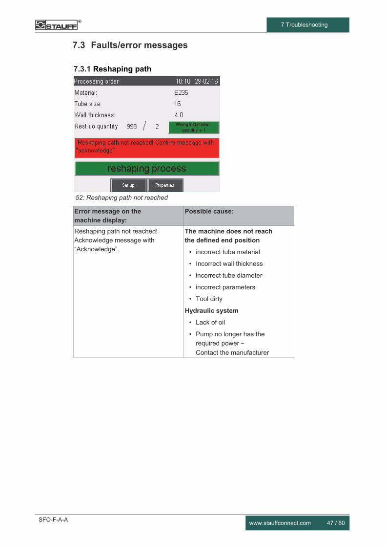
7.3.1 Reshaping path
52: Reshaping path not reached
Error message on the machine display:
Possible cause:
Reshaping path not reached! Acknowledge message with “Acknowledge”.
The machine does not reach the defined end position
• incorrect tube material
• Incorrect wall thickness
• incorrect tube diameter
• incorrect parameters
• Tool dirty
Hydraulic system
• Lack of oil
• Pump no longer has the
required power –
Contact the manufacturer

48 / 60 www.stauffconnect.com
7 Troubleshooting
7.3.2 Target position
53: Target position not reached
Error message on the machine display:
Possible cause:
Target position has not been reached! Confirm with “Acknowledge”, restart if necessary.
Control
• Control fault – Contact
the manufacturer
7.3.3 Reference run
54: Reference run interrupted
Error message on the machine display:
Possible cause:
Reference run interrupted. Lock the bell for new run, then press “Acknowledge”
Handling
• Buttons were not pressed until the end of the reference run. Carry out reference run again.

SFO-F-A-A www.stauffconnect.com 49 / 60
7 Troubleshooting
7.3.4 Parameters
55: Wrong parameters
Error message on the machine display:
Possible cause:
Wrong parameter combination! No shaping path stored.
Handling
• No parameter set is stored for the selected parameter combination material/tube diameter/wall thickness. Check the parameter combination and change it if necessary. Contact the manufacturer if the desired combination is not available.
7.3.5 Direction of rotation
56: Wrong turning direction
Error message on the machine display:
Possible cause:
Wrong turning direction • Phase reverser of the connector set incorrectly. Phase reversers rotating.
50 / 60 www.stauffconnect.com
7 Troubleshooting
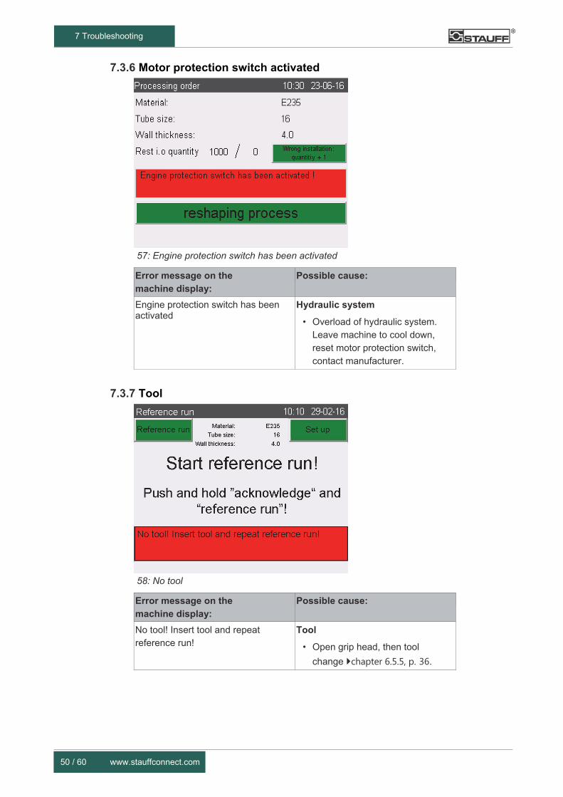
7.3.6 Motor protection switch activated
57: Engine protection switch has been activated
Error message on the machine display:
Possible cause:
Engine protection switch has been activated
Hydraulic system
• Overload of hydraulic system. Leave machine to cool down, reset motor protection switch, contact manufacturer.
7.3.7 Tool
58: No tool
Error message on the machine display:
Possible cause:
No tool! Insert tool and repeat reference run!
Tool
• Open grip head, then tool
change chapter 6.5.5, p. 36.

SFO-F-A-A www.stauffconnect.com 51 / 60
7 Troubleshooting
7.3.8 Other faults
Other faults (cannot be integrated into the machine):
Possible cause:
Contour not processed correctly
Fault: visual check shows insufficient diameter
Tool
• Tool wear
• Wrong shaping jaws
• Wrong tube shaper
• Wrong internal tube support
Tube
• Incorrect wall thickness
• Tolerance exceeded
• Material too hard or too soft
• Wrong preparation
Handling
• Tube not pressed correctly against the tool bottom
• Tube bend too close to the forming end
Tube is stuck in the shaper after assembly
Fault: tube is not pulled out far enough
Tool
• Tool wear
Tube
• Tube slips in the shaping jaws
Pressing does not start
Fault: no reaction from the
machine
Machine
• Defective
Control
• Defective
Operation
• Machine not at the right menu item
• Production quantity reached
Oil loss
Fault: oil leaking
Hydraulic system
• Seals defective
• Machine tipped too far from horizontal position
• Hose/tubing leaking.
Contact the manufacturer
52 / 60 www.stauffconnect.com
7 Troubleshooting
Other faults (cannot be integrated into the machine):
Possible cause:
Machine does not start Power supply
• Appliance not connected to the power supply
• Power supply not switched on
• Cable or connector damage
• Screen defective
Tube slips Tool
• Shaping jaws dirty
• Dirt between the tool segments
• Shaping jaws worn
Shaping jaws do not open Tool
• Shaping jaws dirty
• Dirt between the tool segments
• Springs broken
Tube cannot be inserted Tool
• Tool dirty
• Wrong shaping jaws
• Wrong tube shaper
• Wrong internal tube support
Tube
• Poor deburring
• Wrong tube
• Tube bend too close to the forming end
SFO-F-A-A www.stauffconnect.com 53 / 60
8 Maintenance
8 Maintenance
8.1 Safety
Carrying out maintenance work
Serious or lethal injuries or machine damage
► Maintenance work may only be carried out by Walter Stauffenberg GmbH & Co. KG!
8.2 Inspection and maintenance
The machine has to be sent to Walter Stauffenberg GmbH & Co. KG for maintenance and an oil change every two years or after 200,000 forming processes.
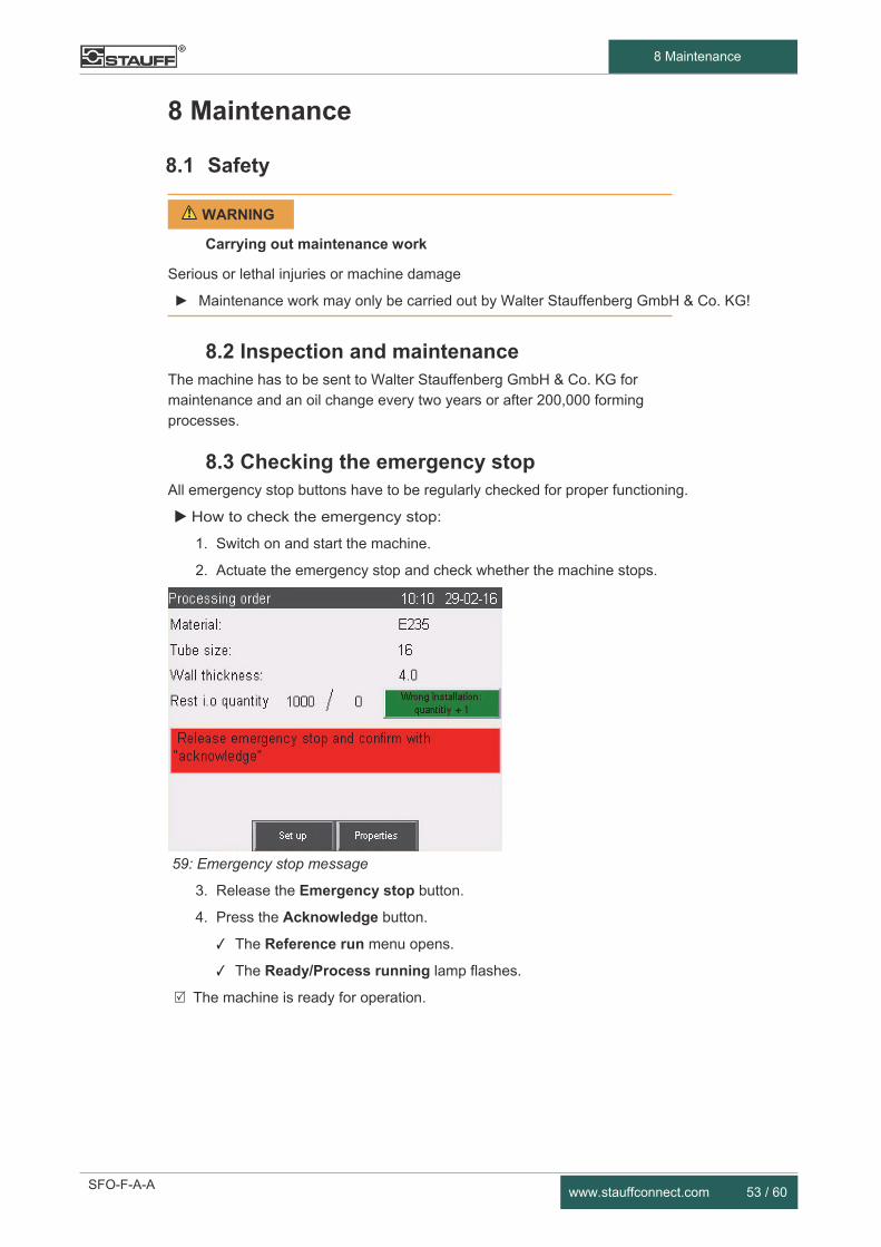
8.3 Checking the emergency stop All emergency stop buttons have to be regularly checked for proper functioning.
How to check the emergency stop:
1. Switch on and start the machine.
2. Actuate the emergency stop and check whether the machine stops.
59: Emergency stop message
3. Release the Emergency stop button.
4. Press the Acknowledge button.
✓ The Reference run menu opens.
✓ The Ready/Process running lamp flashes.
The machine is ready for operation.
WARNING

54 / 60 www.stauffconnect.com
9 Decommissioning
9 Decommissioning
9.1 Safety
Carrying out dismantling work
Serious or lethal injuries
► Dismantling work may only be carried out by authorised qualified personnel!
► Only use suitable tools in proper condition!
► Wear your personal protective equipment for all work!
Lifting loads
Serious or lethal injuries from falling/swaying loads
► Before raising the load, secure all moving components!
► Only use undamaged lifting equipment which is permitted for the weight of the load to be lifted!
► Only attach load attachment gear to the indicated attachment points!
► Never leave loads hanging in the lifting devices without supervision!
► Never stand underneath suspended loads!
Work on the hydraulic system
Eye injuries from ejected hydraulic oil
► Depressurise the machine!
► Any work for which the machine has to be opened may only be performed by Walter Stauffenberg GmbH & Co. KG!
► Wear your personal protective equipment including safety goggles for all work on the hydraulic system!
CAUTION
WARNING
WARNING

SFO-F-A-A www.stauffconnect.com 55 / 60
9 Decommissioning
9.2 Dismantling Dismantle the machine as follows:
1. Take the machine out of service and disconnect from the power supply.
2. Dismantle protective panels and housing.
3. Remove all operating media.
4. Dismantle cables and leads.
5. Remove seals from the bearings.
6. Remove any lubricant from machine parts.
7. Sort plastic, electrical and metal parts.
Solvents and lubricants
Environmental contamination of water and soil
► During dismantling, collect lubricants and cleaning fluids containing solvents in suitable containers!
► For disposal, note the safety data sheets for the emulsions, cleaning agents and lubricants used.
Collect operating media and cleaning fluids containing solvents in appropriate containers to prevent substances hazardous to water from entering the ground or the sewage system!
9.3 Disposal Following final dismantling of the machine, the operating company has to dispose of all used materials and components in keeping with the provisions in force in the country where machine is operated.
Particular care is required for disposing of materials which are hazardous to the environment, e.g.:
• plastic parts
• rubber parts
• electrical parts
• metal parts
• operating fluids and additives
How to handle substances hazardous to water:
1. Use appropriate containers to collect, store, transport and dispose of substances hazardous to water.
2. Dispose of all parts according to material.
3. Always sort by materials for recycling.
IMPORTANT
56 / 60 www.stauffconnect.com
10 EC Declaration of Conformity
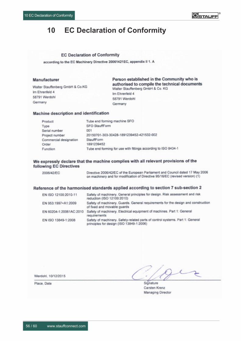
10 EC Declaration of Conformity
EC Declaration of Conformity
according to the EC Machinery Directive 20061421EC, appendix II 1. A
Manufacturer
Walter Stauffenberg GmbH & Co.KG
Im Ehrenfeld 4
58791 Werdohl
Germany
Person established in the Community who is authorised to compile the technical documents Walter Stauffenberg GmbH & Co. KG
Im Ehrenfeld 4
58791 Werdohl
Germany
Machine description and identification
Product Tube end forming machine SFO
Type SFO StauffForm
Serial number 001
Project number 20150701-303-30428-1891239452-421532-002
Commercial designation StauffForm
Order 1891239452
Function Tube end forming for use with fittings according to ISO 8434-1
We expressly declare that the machine complies with all relevant provisions of the following EC Directives
2006/42/EC Directive 2006/42/EC of the European Parliament and Council dated 17 May 2006 on machinery and for modification of Directive 95/16/EC (revised version) (1)
Reference of the harmonised standards applied according to section 7 sub-section 2
EN ISO 12100:2010-11 Safety of machinery. General principles for design. Risk assessment and risk reduction (ISO 12100:2010)
EN 953:1997+A1:2009 Safety of machinery. Guards. General requirements for the design and construction of fixed and movable guards
EN 60204-1:20061AC:2010 Safety of machinery. Electrical equipment of machines. Part 1: General requirements
EN ISO 13849-1:2008 Safety of machinery. Safety-related parts of control systems. Part 1: General principles for design (ISO 13849-1:2006)
Werdohl, 10/12/2015
Place, Date Signature
Carsten Krenz
Managing Director

SFO-F-A-A www.stauffconnect.com 57 / 60
Table of figures
Table of figures 1 Protective devices ......................................................................................................... 10
2 Electrical main switch secured with lock ....................................................................... 11
3 Overview of operating elements ................................................................................... 12
4 Product .......................................................................................................................... 14
5 Tools ............................................................................................................................. 14
6 Size ............................................................................................................................... 14
7 Type plate ..................................................................................................................... 15
8 Start screen................................................................................................................... 21
9 Menu - Language settings ............................................................................................ 21
10 Menu - Reference run/Material ..................................................................................... 22
11 Start reference run ........................................................................................................ 23
12 Releasing the grip head ................................................................................................ 23
13 Pulling out the grip head ............................................................................................... 23
14 Releasing and pulling out the grip head ....................................................................... 24
15 Inserting and locking grip head ..................................................................................... 24
16 Start reference run ........................................................................................................ 25
17 Start reshaping process ................................................................................................ 25
18 Emergency stop message ............................................................................................ 26
19 Menu - Reference run/Material ..................................................................................... 26
20 Menu - Processing order .............................................................................................. 27
21 Menu - Settings level .................................................................................................... 27
22 Menu - Settings languages ........................................................................................... 28
23 Menu - Settings level .................................................................................................... 29
24 Menu - System .............................................................................................................. 29
25 Menu - Input pad for date and time .............................................................................. 30
26 Tool counter .................................................................................................................. 30
27 Overview - Function of the inputs and outputs ............................................................. 31
28 Menu - Number of pieces ............................................................................................. 31
29 Menu - Processing order .............................................................................................. 32
30 Menu - Job set-up ......................................................................................................... 32
31 Menu - Material set-up .................................................................................................. 33
32 Menu - Job set-up ......................................................................................................... 33
33 Menu - Set up tube size ................................................................................................ 34
34 Menu - Job set-up ......................................................................................................... 34
35 Menu - Set up wall thickness ........................................................................................ 35
36 Menu - Input path number of pieces ............................................................................. 36
37 Menu - Job set-up ......................................................................................................... 37
38 Checking the tool .......................................................................................................... 37

58 / 60 www.stauffconnect.com
Table of figures
39 Releasing and pulling out the grip head ....................................................................... 37
40 Inserting the tube shaper ............................................................................................. 39
41 Installing the shaping jaws ........................................................................................... 39
42 Shaping jaws installed .................................................................................................. 40
43 Inserting tool ................................................................................................................. 40
44 Inserting grip head ........................................................................................................ 40
45 Start reference run ....................................................................................................... 41
46 Menu - Processing order .............................................................................................. 41
47 Start reshaping process ............................................................................................... 42
48 Product with sleeve nut ................................................................................................ 42
49 Pushing in the tube ....................................................................................................... 43
50 Removing the tube ....................................................................................................... 43
51 Job stopped .................................................................................................................. 44
52 Reshaping path not reached ........................................................................................ 47
53 Target position not reached ......................................................................................... 48
54 Reference run interrupted ............................................................................................ 48
55 Wrong parameters ........................................................................................................ 49
56 Wrong turning direction ................................................................................................ 49
57 Engine protection switch has been activated ............................................................... 50
58 No tool .......................................................................................................................... 50
59 Emergency stop message ............................................................................................ 53

SFO-F-A-A www.stauffconnect.com 59 / 60
Key word list
Key word list
C
Cleaning 44 Commissioning 21
D
Decommissioning 54
E
Emergency stop 26, 53
F
Forming cylinder 38 Function 13
G
Grip head 12, 24, 37
I
Internal tube support 14, 38 M
Machine cleaning 44 decommissioning 54 overview 10, 14 switching off 44 switching on 21
Maintenance 53
O
Operating company Task 8
Operating elements 12 P
Personal protective equipment 9 Personal 9 Product 14 Protective devices 10 Protective equipment 9 PSA 9 Q
Qualification 9
R
Reference run 22, 41 References 6
S
Safety devices 10 Safety instructions 7 Safety markings 9 Setting up a job 32 Shaping jaws 14, 38 Signal word boxes 5 Signal word 6 Sleeve note 42 Spare parts 16 Switching off 44 Switching on 21 System properties 29
T Task instructions 6 Technical data 13 Tool
changing 36 overview 14 setting up 36
Transport 17 Troubleshooting 46 Tube shaper 14, 38 Type plate 15
W Warnings 5

Feedback Let us know about any questions, suggestions or criticism you might have about your machine or this documentation:
Walter Stauffenberg GmbH & Co. KG Im Ehrenfeld 4 58791 Werdohl Germany
Telephone: +49 23 92 916 0 Fax: +49 23 92 916 160
[email protected] www.stauffconnect.com
Thank you for your support:
Author of this manual:
Kruppstraße 82-100 45145 Essen Telephone: +49 (0) 201 185270-0 Fax: +49 (0) 201 185270-5 Email: [email protected] Internet: www.ed-t.de