Embed Size (px)
Citation preview
Journal of Mechanical Engineering and Automation 2016, 6(5): 128-138
DOI: 10.5923/j.jmea.20160605.05
Transient Heat Transfer and Energy Balance Model for
Hydrodynamic Torque Converters while Operating at
Extreme Speed Ratio
Darrell Robinette*, Jason Blough
Dep’t Mechanical Engineering-Engineering Mechanics, Michigan Technological University, Houghton, MI, USA
Abstract This investigation details the development of a simple transient model to predict the bulk toroidal flow fluid
temperature of the automotive torque converter based upon an energy balance and the derivation of an overall convective heat
transfer correlation for the entire turbomachine. Data collected on a torque converter specific dynamometer setup is used to
derive a Nusselt correlation for overall convective heat transfer from the shell using measured parameters. Dimensional
analysis applied to three torque converters of nearly exact geometric similitude was used to show the applicability of the
correlation to prediction of the overall external convective heat transfer mechanism. Discussion is focused on operation at
low speed ratios for varying lengths of time. This particular condition represents the worst-case scenario for torque converter
operating efficiency and heat rejection. It was found that the external heat rejection from the torque converter shell surface is
a function of the rotational Reynolds number and proportional to the characteristic dimensionless performance number unit
input speed. The model is shown to trend with temperature measurements made at the external shell of the torque converter
over a variety of zero speed ratio transient maneuvers. Overall, the first order, linear differential equation model and Nusselt
correlation for overall heat transfer are a first step in developing an adequate tool for use in future torque converter designs
predicated on scalability of the turbomachines performance quantified through dimensionless numbers.
Keywords Torque converter, Transient heat transfer, Nusselt correlation, Dimensional analysis
1. Introduction
The torque converter is a particular class of turbomachine
used in a wide variety of power transfer applications to
couple the prime mover to the gear system of an automatic
transmission. Torque converters can be found in on or off
highway powertrain applications and is most commonly
utilized in automatic transmissions to enhance the initial
acceleration performance of the vehicle. It is also a means
of improving system durability since the torque converter
has superior cooling characteristics and does not experience
wear like that of a friction launch clutch. The modern
three-element torque converter consists of a closed loop
torus containing a mixed flow pump, a mixed flow turbine
and an axial flow stator. The device is required to operate
over a range of speed ratios from zero to values greater than
one. Speed ratio is defined as the rotation of turbine speed
divided by pump speed. At zero speed ratio, maximum
torque multiplication is achieved, while maximum
efficiency occurs at speed ratios between 0.85 and 0.95
* Corresponding author:
[email protected] (Darrell Robinette)
Published online at http://journal.sapub.org/jmea
Copyright © 2016 Scientific & Academic Publishing. All Rights Reserved
depending on the details of the design. As a result, the flow
field is three-dimensional within the torus, producing
secondary flow structures and the potential for two-phase
mixture, e.g. cavitation, depending on the severity of the
specific operating condition. A detailed description of the
torque converter and previous experimental or numerical
studies can be found in [1-3] for example.
Selection of a torque converter design is performed
numerically to match the torque and speed characteristics of
the prime mover to a particular powertrain application to
balance acceleration and efficiency for the range of operation
conditions expected. The geometry of the torus and
individual elements is developed through iterative CFD and
other numerical methods, and then validated through
physical hardware testing on a dynamometer to achieve
specific performance targets, see [4-8]. To meet physical
packaging constraints or to minimize the occurrence of
performance inhibiting toroidal flow structures such as
stalled or reversed flow and large volume cavitation, further
refinement of the torus dimensions, pump and turbine blade
angles and stator blade geometry may be undertaken.
Additionally, the working conditions of the hydraulic fluid
imposed upon the torque converter pressure vessel can be
calibrated to suppress cavitation or create sufficient through
flow cooling to maintain adequate toroidal flow operating
Journal of Mechanical Engineering and Automation 2016, 6(5): 128-138 129
temperatures.
In automotive powertrain applications, the mega trend is
towards increasingly power dense prime movers with greater
torque availability at lower operating speeds due to
turbocharging. Simultaneously, the dimensions of the torque
converter torus are being significantly reduced to
accommodate increased gear and clutch content of the
automatic transmission to achieve 8, 9, 10 or more forward
fixed gear ratios. Additionally, more torus space is being
allocated for the lockup clutch damper to bypass the
hydrodynamic circuit to further reduce fuel consumption
once the vehicle has launched, see Figure 1. The
combination of these two design trends results in greater
demands on the turbomachine, particularly for extended
operation at extreme speed ratios and elevated levels of
torque transfer. The purpose of this investigation is to
develop a first principal based model validated with
experimental data that can predict the internal toroidal flow
temperature of the torque converter. The method presented is
based upon that reported by [9] for powertrain cooling and
protection strategy based upon a predicted temperature
internal to the torque converter. Predictions of these
temperatures can be critical in determining required cooling
capacity, establishing operating limitations for component
durability, preventing cavitation and preservation of oil
quality from excessive thermal cycling.
Figure 1. Cross-sections of typical three element, automotive torque
converters showing typical design trend over past 20 years, from left to right,
oldest to newest
2. Torque Converter Fundamentals
The principals of torque converter operation and details of
flow theory are contained in a number of sources found in the
literature, [1, 4-8 and 10-14], for example. A brief discussion
is provided here for reference and continuity of the material
contained in this paper.
2.1. Performance Characteristics
Torque converter performance is typically defined by
dimensionless or semi-dimensionless quantities to match the
turbomachine to specific applications are summarized in
Equations 1 through 3. The quantities of torque ratio, TR,
output (turbine) to input (engine or pump) torques and
K-factor, K, input speed to square root of input torque are
plotted versus speed ratio, SR, output to input speeds and
forms the mainstay of matching torque converter – prime
mover, see Figure 2.
p
tTR
(1)
p
pNK
(2)
p
t
N
NSR (3)
K-factor is transformed into the dimensionless quantity
unit input speed, , with the addition of diameter, D, to the
5/2 power and square root of the density, ρ, of the operating
fluid,
p
p DN
5
(4)
Unit input speed is the inverse, square root of the more
common dimensionless number referred to as the torque
coefficient. The designation for a given torque converter are
normally specified by the diameter of the pump and the
K-factor value realized at zero speed ratio, known as stall.
2.2. One-Dimensional Flow Theory
A significant amount detailed research, both analytical
and experimental, has been performed on torque converters,
[4-8 and 10-14]. The fundamental laws of fluid mechanics
and thermodynamics can be applied to create a
one-dimensional flow model capable of useful predictions.
The principles of conservation of angular momentum and
energy for a control volume, CV, encompassing the fluid and
bladed surfaces of the turbomachine elements are used to the
define the model as given by Equations 5 and 6, though a
thorough description is outside of scope for this paper and is
readily available in the literature, see [10-14].
AdvvrdVvrt
CV
(5)
WQdt
dE (6)
The key output of the one-dimensional model are torus
fluid operating parameters that are not easily measured
experimentally, namely the volumetric or mass flow rate of
the toroidal flow. Having this information is important in the
prediction of heat transfer from the toroidal flow to the
external surface of the torque converter shell. This topic will
be discussed in detail later in the paper. One-dimensional
models for the torque converters tested for this investigation
and example data showing correlation with dynamometer
data is provided in Figure 2. Excellent correlation of the
model is noted at low speed ratios, which are the focus of the
discussion. Figure 3 contains toroidal mass flow rate for the
stall, zero speed ratio, condition at a range of pump torques

130 Darrell Robinette et al.: Transient Heat Transfer and Energy Balance Model for
Hydrodynamic Torque Converters while Operating at Extreme Speed Ratio
and mass flow rate across the speed ratio range at a pump
torque of 150 Nm. At stall, mass flow rate is a linear function
with pump torque, corresponding to an increasing pressure
head, which will be later shown to adversely affect cooling
through at elevated pump speeds. Toroidal mass flow rate
follows an inverse power law with respect to speed ratio.
Figure 2. Correlation of one-dimensional flow theory model with
measured dynamometer data
Figure 3. Toroidal mass flow rate as a function of pump torque at stall and
speed ratio for a fixed pump torque
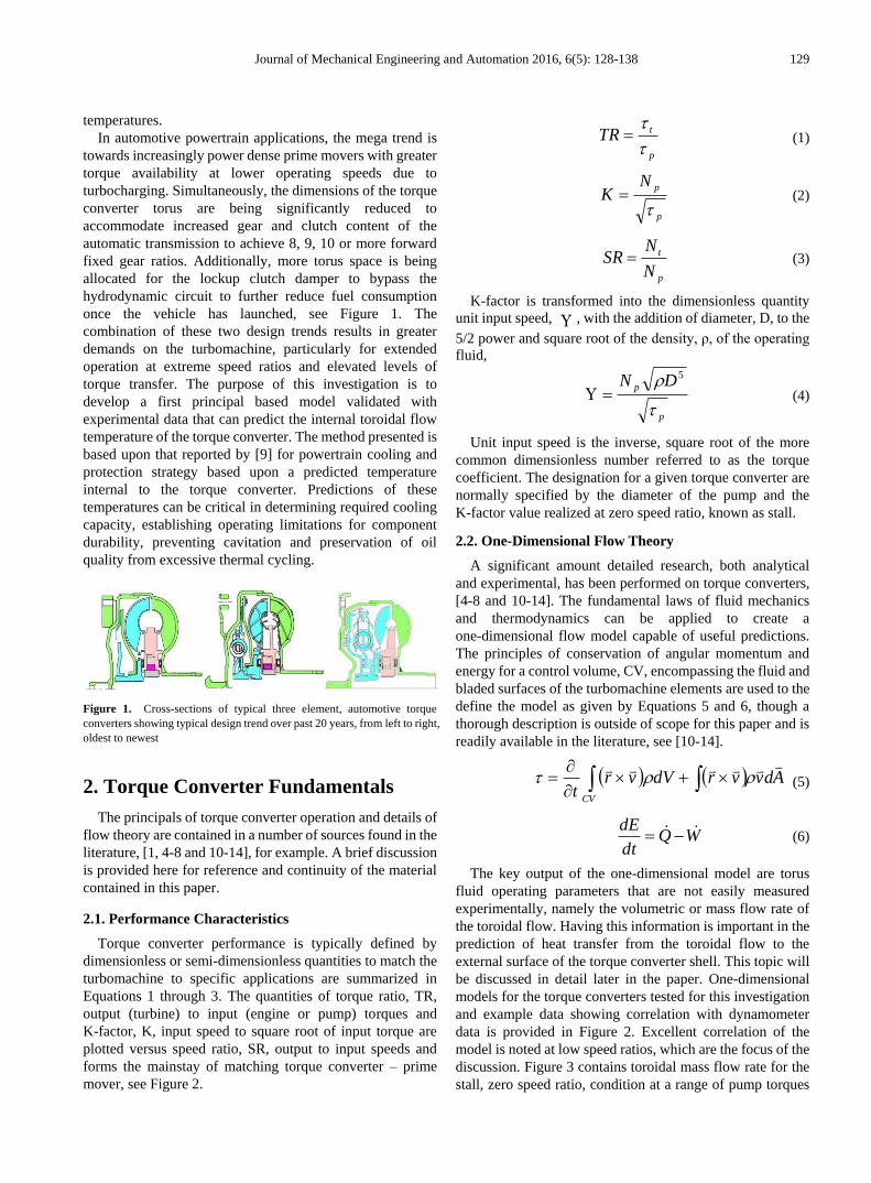
2.3. Energy Balance
An energy balance for the torque converter operating with
or without the lockup clutch applied is shown in Figure 4.
Shaft work input from the prime mover at the cover and
pump (green) is converted to useful shaft work through the
torus fluid and extracted in the turbine and lockup clutch
damper (blue) assembly and then transmitted to the
automatic transmission via the turbine shaft. The remainder
of the energy not converted to useful shaft work is rejected as
heat through two principal pathways. Cooling through flow,
cQ , is supplied to the torque converter from the automatic
transmissions high pressure oil supply which enters through
the turbine shaft and mixes with the torus flow and exhausts
back to the sump via passages between stator and pump
shafts. Energy is also dissipated as heat from the torus to the
external shell via forced convection from torus to shell,
torusQ , and shell to air, shellQ , as well as conduction
through the shell. The overall heat transfer mechanism from
the external surface can be difficult to measure or quantify
using traditional methods and will be a focus of discussion in
the paper.
Based upon the energy balance in Figure 4, a linear, first
order, differential equation can be written for the
temperature of the toroidal fluid temperature, torusT , as seen
in Equation 7. It should be noted that for this model, it is
assumed that torus temperature is equivalent to the exhaust
or outlet temperature from the torque converter.
WTTCm
TTUAdt
dTCm
torusinitcoilpoil
torusairoverall
torus
oilpoil
,,
,
(7)
The individual heat transfer mechanisms of torusQ and
shellQ in additional to conduction through the shell can be
combined into an overall heat transfer term, shelloverallQ , ,
given by,
torusairoverallshelloverall TTUAQ , (8)
The solution of the differential equation of Equation 7 for
torus temperature becomes,
tt
inittorus eeTT
1 (9)
where and are equal to the following,
oilpoil
initc
oil
oil
air
oilpoil
overall
Cm
WT
m
mT
Cm
UA
,
,
,
(10)
and
oilpoil
overall
oil
oil
Cm
UA
m
m
,
(11)
Assuming an initial condition for the torus temperature,
, to be equal to the cooling through flow inlet
temperature, , which is assumed to be time invariant.
A simplification can be made to Equation (9) if the amount
of heat energy rejected through the external surface is
assumed a known quantity, ,
WTTCm
Qdt
dTCm
torusinitcoilpoil
shelloveralltorus
oilpoil
,,
,, (12)
which results in the following solution for torus temperature
with the same initial condition,
initT
initcT ,
shelloverallQ ,
Journal of Mechanical Engineering and Automation 2016, 6(5): 128-138 131
Figure 4. Energy balance across a three torque converter with lockup clutch and cooling through flow circuit
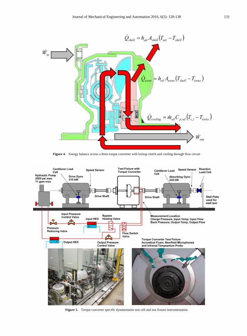
Figure 5. Torque converter specific dynamometer test cell and test fixture instrumentation
132 Darrell Robinette et al.: Transient Heat Transfer and Energy Balance Model for
Hydrodynamic Torque Converters while Operating at Extreme Speed Ratio
,,
, ,
1
oil
oil
oil
oil
mt
mtorus init
mt
overall shell mc init
oil p oil oil p oil
T T e
Q WT e
m C m C
(13)
Equation 13 will be the foundation for the remainder of the
discussion in this paper for estimating the toroidal flow
temperature of the torque converter during transient
operation. Detail will be provided in the results section as to
the mechanism enabling the simplification through the
development of a proportional relationship between overall
external surface heat rejection and input power based upon
the specific design details of the torque converter.
3. Experimental Setup
A torque converter specific dynamometer test cell, Figure
5, was used to test three torque converters of nearly exact
geometric scaling, see Figure 6, at stall. The testing was
originally performed to determine the appropriateness of
applying the dimensional analysis to developing a prediction
tool for incipient cavitation in torque converters using a
nearfield acoustical technique, see [8]. The dynamometer
data collected during this testing can be further utilized to
develop a model to predict torus temperatures during
transient, high input power maneuvers when operating at low
overall efficiency. The dynamometer was setup for the stall
condition, zero output speed, only and all three torque
converters were painted flat black to create the same
radiation surface emissivity and to enable a more suitable
infrared surface temperature measurement. The details of
this measurement setup can be seen in Figure 5, along with
nearfield microphones to detect cavitation enclosed in a
nitrile cover to prevent oil contamination. The torque
converters tested were 245, 258 and 300 mm diameters as
measured at the pump outside diameter and had a stall unit
input speed rating of 140, corresponding to K-factors of 163,
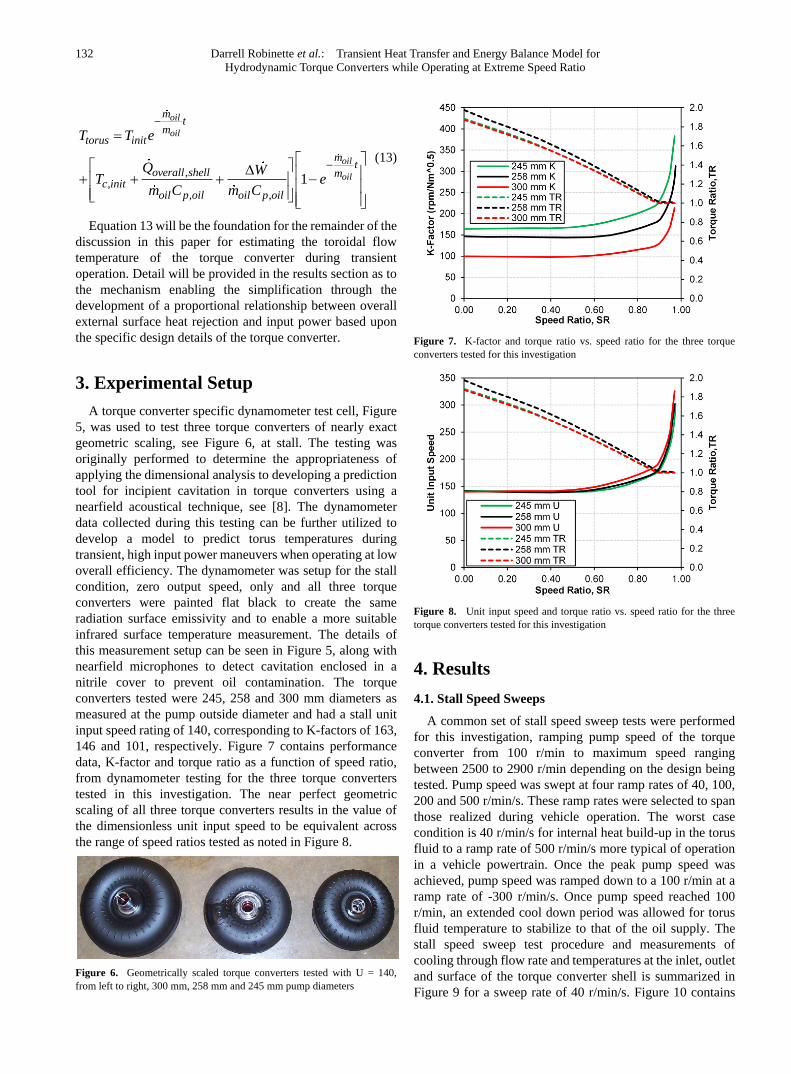
146 and 101, respectively. Figure 7 contains performance
data, K-factor and torque ratio as a function of speed ratio,
from dynamometer testing for the three torque converters
tested in this investigation. The near perfect geometric
scaling of all three torque converters results in the value of
the dimensionless unit input speed to be equivalent across
the range of speed ratios tested as noted in Figure 8.
Figure 6. Geometrically scaled torque converters tested with U = 140,
from left to right, 300 mm, 258 mm and 245 mm pump diameters
Figure 7. K-factor and torque ratio vs. speed ratio for the three torque
converters tested for this investigation
Figure 8. Unit input speed and torque ratio vs. speed ratio for the three
torque converters tested for this investigation
4. Results
4.1. Stall Speed Sweeps
A common set of stall speed sweep tests were performed
for this investigation, ramping pump speed of the torque
converter from 100 r/min to maximum speed ranging
between 2500 to 2900 r/min depending on the design being
tested. Pump speed was swept at four ramp rates of 40, 100,
200 and 500 r/min/s. These ramp rates were selected to span
those realized during vehicle operation. The worst case
condition is 40 r/min/s for internal heat build-up in the torus
fluid to a ramp rate of 500 r/min/s more typical of operation
in a vehicle powertrain. Once the peak pump speed was
achieved, pump speed was ramped down to a 100 r/min at a
ramp rate of -300 r/min/s. Once pump speed reached 100
r/min, an extended cool down period was allowed for torus
fluid temperature to stabilize to that of the oil supply. The
stall speed sweep test procedure and measurements of
cooling through flow rate and temperatures at the inlet, outlet
and surface of the torque converter shell is summarized in
Figure 9 for a sweep rate of 40 r/min/s. Figure 10 contains
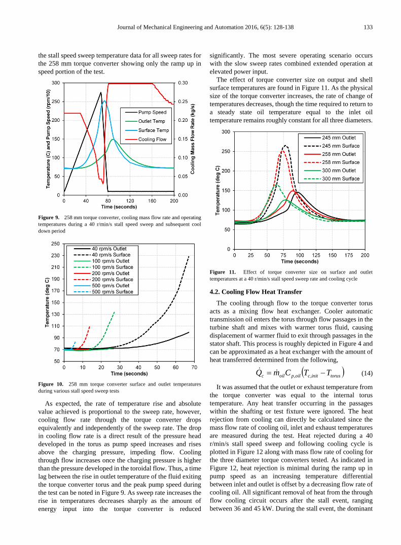
Journal of Mechanical Engineering and Automation 2016, 6(5): 128-138 133
the stall speed sweep temperature data for all sweep rates for
the 258 mm torque converter showing only the ramp up in
speed portion of the test.
Figure 9. 258 mm torque converter, cooling mass flow rate and operating
temperatures during a 40 r/min/s stall speed sweep and subsequent cool
down period
Figure 10. 258 mm torque converter surface and outlet temperatures
during various stall speed sweep tests
As expected, the rate of temperature rise and absolute
value achieved is proportional to the sweep rate, however,
cooling flow rate through the torque converter drops
equivalently and independently of the sweep rate. The drop
in cooling flow rate is a direct result of the pressure head
developed in the torus as pump speed increases and rises
above the charging pressure, impeding flow. Cooling
through flow increases once the charging pressure is higher
than the pressure developed in the toroidal flow. Thus, a time
lag between the rise in outlet temperature of the fluid exiting
the torque converter torus and the peak pump speed during
the test can be noted in Figure 9. As sweep rate increases the
rise in temperatures decreases sharply as the amount of
energy input into the torque converter is reduced
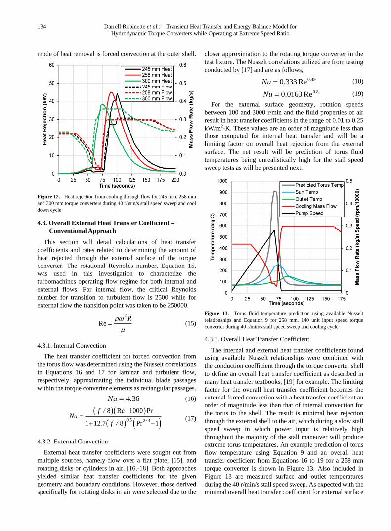
significantly. The most severe operating scenario occurs
with the slow sweep rates combined extended operation at
elevated power input.
The effect of torque converter size on output and shell
surface temperatures are found in Figure 11. As the physical
size of the torque converter increases, the rate of change of
temperatures decreases, though the time required to return to
a steady state oil temperature equal to the inlet oil
temperature remains roughly constant for all three diameters.
Figure 11. Effect of torque converter size on surface and outlet
temperatures at a 40 r/min/s stall speed sweep rate and cooling cycle
4.2. Cooling Flow Heat Transfer
The cooling through flow to the torque converter torus
acts as a mixing flow heat exchanger. Cooler automatic
transmission oil enters the torus through flow passages in the
turbine shaft and mixes with warmer torus fluid, causing
displacement of warmer fluid to exit through passages in the
stator shaft. This process is roughly depicted in Figure 4 and
can be approximated as a heat exchanger with the amount of
heat transferred determined from the following,
torusinitcoilpoilc TTCmQ ,, (14)
It was assumed that the outlet or exhaust temperature from
the torque converter was equal to the internal torus
temperature. Any heat transfer occurring in the passages
within the shafting or test fixture were ignored. The heat
rejection from cooling can directly be calculated since the
mass flow rate of cooling oil, inlet and exhaust temperatures
are measured during the test. Heat rejected during a 40
r/min/s stall speed sweep and following cooling cycle is
plotted in Figure 12 along with mass flow rate of cooling for
the three diameter torque converters tested. As indicated in
Figure 12, heat rejection is minimal during the ramp up in
pump speed as an increasing temperature differential
between inlet and outlet is offset by a decreasing flow rate of
cooling oil. All significant removal of heat from the through
flow cooling circuit occurs after the stall event, ranging
between 36 and 45 kW. During the stall event, the dominant
134 Darrell Robinette et al.: Transient Heat Transfer and Energy Balance Model for
Hydrodynamic Torque Converters while Operating at Extreme Speed Ratio
mode of heat removal is forced convection at the outer shell.
Figure 12. Heat rejection from cooling through flow for 245 mm, 258 mm
and 300 mm torque converters during 40 r/min/s stall speed sweep and cool
down cycle
4.3. Overall External Heat Transfer Coefficient –
Conventional Approach
This section will detail calculations of heat transfer
coefficients and rates related to determining the amount of
heat rejected through the external surface of the torque
converter. The rotational Reynolds number, Equation 15,
was used in this investigation to characterize the
turbomachines operating flow regime for both internal and
external flows. For internal flow, the critical Reynolds
number for transition to turbulent flow is 2500 while for
external flow the transition point was taken to be 250000.
2
ReR
(15)
4.3.1. Internal Convection
The heat transfer coefficient for forced convection from
the torus flow was determined using the Nusselt correlations
in Equations 16 and 17 for laminar and turbulent flow,
respectively, approximating the individual blade passages
within the torque converter elements as rectangular passages.
36.4Nu (16)
0 5 2 3
8 Re 1000 Pr
1 12 7 8 Pr 1. /
f /Nu
. f /
(17)
4.3.2. External Convection
External heat transfer coefficients were sought out from
multiple sources, namely flow over a flat plate, [15], and
rotating disks or cylinders in air, [16,-18]. Both approaches
yielded similar heat transfer coefficients for the given
geometry and boundary conditions. However, those derived
specifically for rotating disks in air were selected due to the
closer approximation to the rotating torque converter in the
test fixture. The Nusselt correlations utilized are from testing
conducted by [17] and are as follows,
49.0Re333.0Nu (18)
8.0Re0163.0Nu (19)
For the external surface geometry, rotation speeds
between 100 and 3000 r/min and the fluid properties of air
result in heat transfer coefficients in the range of 0.01 to 0.25
kW/m2-K. These values are an order of magnitude less than
those computed for internal heat transfer and will be a
limiting factor on overall heat rejection from the external
surface. The net result will be prediction of torus fluid
temperatures being unrealistically high for the stall speed
sweep tests as will be presented next.
Figure 13. Torus fluid temperature prediction using available Nusselt
relationships and Equation 9 for 258 mm, 140 unit input speed torque
converter during 40 r/min/s stall speed sweep and cooling cycle
4.3.3. Overall Heat Transfer Coefficient
The internal and external heat transfer coefficients found
using available Nusselt relationships were combined with
the conduction coefficient through the torque converter shell
to define an overall heat transfer coefficient as described in
many heat transfer textbooks, [19] for example. The limiting
factor for the overall heat transfer coefficient becomes the
external forced convection with a heat transfer coefficient an
order of magnitude less than that of internal convection for
the torus to the shell. The result is minimal heat rejection
through the external shell to the air, which during a slow stall
speed sweep in which power input is relatively high
throughout the majority of the stall maneuver will produce
extreme torus temperatures. An example prediction of torus
flow temperature using Equation 9 and an overall heat
transfer coefficient from Equations 16 to 19 for a 258 mm
torque converter is shown in Figure 13. Also included in
Figure 13 are measured surface and outlet temperatures
during the 40 r/min/s stall speed sweep. As expected with the
minimal overall heat transfer coefficient for external surface
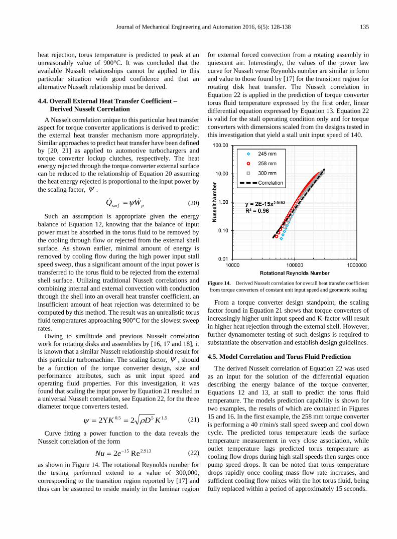
Journal of Mechanical Engineering and Automation 2016, 6(5): 128-138 135
heat rejection, torus temperature is predicted to peak at an
unreasonably value of 900°C. It was concluded that the
available Nusselt relationships cannot be applied to this
particular situation with good confidence and that an
alternative Nusselt relationship must be derived.
4.4. Overall External Heat Transfer Coefficient –
Derived Nusselt Correlation
A Nusselt correlation unique to this particular heat transfer
aspect for torque converter applications is derived to predict
the external heat transfer mechanism more appropriately.
Similar approaches to predict heat transfer have been defined
by [20, 21] as applied to automotive turbochargers and
torque converter lockup clutches, respectively. The heat
energy rejected through the torque converter external surface
can be reduced to the relationship of Equation 20 assuming
the heat energy rejected is proportional to the input power by
the scaling factor, .
psurf WQ (20)
Such an assumption is appropriate given the energy
balance of Equation 12, knowing that the balance of input
power must be absorbed in the torus fluid to be removed by
the cooling through flow or rejected from the external shell
surface. As shown earlier, minimal amount of energy is
removed by cooling flow during the high power input stall
speed sweep, thus a significant amount of the input power is
transferred to the torus fluid to be rejected from the external
shell surface. Utilizing traditional Nusselt correlations and
combining internal and external convection with conduction
through the shell into an overall heat transfer coefficient, an
insufficient amount of heat rejection was determined to be
computed by this method. The result was an unrealistic torus
fluid temperatures approaching 900°C for the slowest sweep
rates.
Owing to similitude and previous Nusselt correlation
work for rotating disks and assemblies by [16, 17 and 18], it
is known that a similar Nusselt relationship should result for
this particular turbomachine. The scaling factor, , should
be a function of the torque converter design, size and
performance attributes, such as unit input speed and
operating fluid properties. For this investigation, it was
found that scaling the input power by Equation 21 resulted in
a universal Nusselt correlation, see Equation 22, for the three
diameter torque converters tested.
5.155.0 22 KDK (21)
Curve fitting a power function to the data reveals the
Nusselt correlation of the form
913.215 Re2 eNu (22)
as shown in Figure 14. The rotational Reynolds number for
the testing performed extend to a value of 300,000,
corresponding to the transition region reported by [17] and
thus can be assumed to reside mainly in the laminar region
for external forced convection from a rotating assembly in
quiescent air. Interestingly, the values of the power law
curve for Nusselt verse Reynolds number are similar in form
and value to those found by [17] for the transition region for
rotating disk heat transfer. The Nusselt correlation in
Equation 22 is applied in the prediction of torque converter
torus fluid temperature expressed by the first order, linear
differential equation expressed by Equation 13. Equation 22
is valid for the stall operating condition only and for torque
converters with dimensions scaled from the designs tested in
this investigation that yield a stall unit input speed of 140.
Figure 14. Derived Nusselt correlation for overall heat transfer coefficient
from torque converters of constant unit input speed and geometric scaling
From a torque converter design standpoint, the scaling
factor found in Equation 21 shows that torque converters of
increasingly higher unit input speed and K-factor will result
in higher heat rejection through the external shell. However,
further dynamometer testing of such designs is required to
substantiate the observation and establish design guidelines.
4.5. Model Correlation and Torus Fluid Prediction
The derived Nusselt correlation of Equation 22 was used
as an input for the solution of the differential equation
describing the energy balance of the torque converter,
Equations 12 and 13, at stall to predict the torus fluid
temperature. The models prediction capability is shown for
two examples, the results of which are contained in Figures
15 and 16. In the first example, the 258 mm torque converter
is performing a 40 r/min/s stall speed sweep and cool down
cycle. The predicted torus temperature leads the surface
temperature measurement in very close association, while
outlet temperature lags predicted torus temperature as
cooling flow drops during high stall speeds then surges once
pump speed drops. It can be noted that torus temperature
drops rapidly once cooling mass flow rate increases, and
sufficient cooling flow mixes with the hot torus fluid, being
fully replaced within a period of approximately 15 seconds.
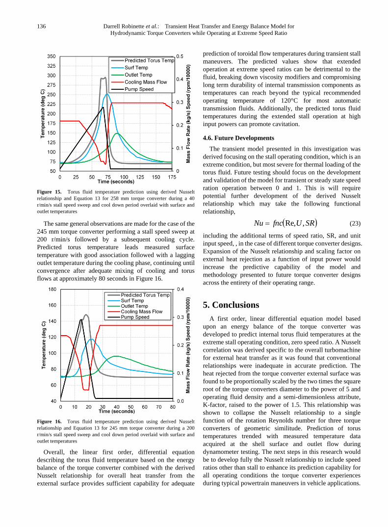
136 Darrell Robinette et al.: Transient Heat Transfer and Energy Balance Model for
Hydrodynamic Torque Converters while Operating at Extreme Speed Ratio
Figure 15. Torus fluid temperature prediction using derived Nusselt
relationship and Equation 13 for 258 mm torque converter during a 40
r/min/s stall speed sweep and cool down period overlaid with surface and
outlet temperatures
The same general observations are made for the case of the
245 mm torque converter performing a stall speed sweep at
200 r/min/s followed by a subsequent cooling cycle.
Predicted torus temperature leads measured surface
temperature with good association followed with a lagging
outlet temperature during the cooling phase, continuing until
convergence after adequate mixing of cooling and torus
flows at approximately 80 seconds in Figure 16.
Figure 16. Torus fluid temperature prediction using derived Nusselt
relationship and Equation 13 for 245 mm torque converter during a 200
r/min/s stall speed sweep and cool down period overlaid with surface and
outlet temperatures
Overall, the linear first order, differential equation
describing the torus fluid temperature based on the energy
balance of the torque converter combined with the derived
Nusselt relationship for overall heat transfer from the
external surface provides sufficient capability for adequate
prediction of toroidal flow temperatures during transient stall
maneuvers. The predicted values show that extended
operation at extreme speed ratios can be detrimental to the
fluid, breaking down viscosity modifiers and compromising
long term durability of internal transmission components as
temperatures can reach beyond the typical recommended
operating temperature of 120°C for most automatic
transmission fluids. Additionally, the predicted torus fluid
temperatures during the extended stall operation at high
input powers can promote cavitation.
4.6. Future Developments
The transient model presented in this investigation was
derived focusing on the stall operating condition, which is an
extreme condition, but most severe for thermal loading of the
torus fluid. Future testing should focus on the development
and validation of the model for transient or steady state speed
ration operation between 0 and 1. This is will require
potential further development of the derived Nusselt
relationship which may take the following functional
relationship,
SRUfncNu ,Re, (23)
including the additional terms of speed ratio, SR, and unit
input speed, , in the case of different torque converter designs.
Expansion of the Nusselt relationship and scaling factor on
external heat rejection as a function of input power would
increase the predictive capability of the model and
methodology presented to future torque converter designs
across the entirety of their operating range.
5. Conclusions
A first order, linear differential equation model based
upon an energy balance of the torque converter was
developed to predict internal torus fluid temperatures at the
extreme stall operating condition, zero speed ratio. A Nusselt
correlation was derived specific to the overall turbomachine
for external heat transfer as it was found that conventional
relationships were inadequate in accurate prediction. The
heat rejected from the torque converter external surface was
found to be proportionally scaled by the two times the square
root of the torque converters diameter to the power of 5 and
operating fluid density and a semi-dimensionless attribute,
K-factor, raised to the power of 1.5. This relationship was
shown to collapse the Nusselt relationship to a single
function of the rotation Reynolds number for three torque
converters of geometric similitude. Prediction of torus
temperatures trended with measured temperature data
acquired at the shell surface and outlet flow during
dynamometer testing. The next steps in this research would
be to develop fully the Nusselt relationship to include speed
ratios other than stall to enhance its prediction capability for
all operating conditions the torque converter experiences
during typical powertrain maneuvers in vehicle applications.

Journal of Mechanical Engineering and Automation 2016, 6(5): 128-138 137
Nomenclature
Variable Description Units
A Area m2
pC Specific heat kJ/kg
CV Control volume -
D Diameter m
E Energy kJ
K Torque converter K-factor r/min/Nm0.5
N Rotational speed r/min
Nu Nusselt number -
Q Volumetric flow rate m3/s
Q Heat transfer kW
Pr Prandlt number -
R Radius m
Re Reynold number -
SR Torque converter speed ratio -
Torque Nm
T Temperature C
TR Torque converter torque ratio -
U Overall heat transfer coefficient W/m2-K
Torque converter unit input speed -
W Power kW
dA Torque converter element differential area m2
dV Torque converter fluid differential volume m3
f Friction factor -
m Mass kg
m Mass flow rate kg/s
r
Position vector m
t Time s
v
Velocity vector rad/s
Dynamic viscosity kg/m-s
Density kg/m3
Angular velocity rad/s
Subscript Description
c Torque converter cooling through flow
init Initial
oil Torque converter oil
overall Overall heat
p
Pump
shell Torque converter shell
surf
Surface
t Turbine
torus Torque converter torus
REFERENCES
[1] Jandasek, V. J., "Design of Single-Stage, Three Element Torque Converter," SAE Design Practices: Pass. Car Auto. Trans., 3rd Ed., 75-102, 1961.
[2] Abe, H., Tsuruoka, M., Muto, A., Kato, M. and Fujiwara, H., “Development of Super Flat Torque Converter with Multi Plate Lock-up Clutch,” SAE Technical Report, 2009-01-0141, 2009, doi: 10.4271/2009-01-0141.
[3] Usui, T., Okaji, T., Muramatsu, T., and Yamashita, Y., "Development of a Compact Ultra-Flat Torque Converter Equipped with a High-Performance Damper," SAE Int. J. Engines 8(3):1374-1378, 2015, doi:10.4271/2015-01-1088.4.
[4] Bahr, H. M., Flack, R. D., By R. R. and Zhang, J. J., “Laser Velocimeter Measurements in the Stator of a Torque Converter,” SAE J. of Pass. Cars, 99:1625-1634, 1990.
[5] By, R. R. and Lakshminarayana, B., “Measurement and Analysis of Static Pressure Field in a Torque Converter Turbine," ASME J. of Fluids Eng., 117(3): 473-478, 1995.
[6] Schweitzer J., Gandham, J., “Computational Fluid Dynamics in Torque Converters: Validation and Application,” International Journal of Rotating Machinery, vol. 9, pp. 411-418, 2003.
[7] Robinette, D., Grimmer, M., Horgan, J., Kennell, J. et al., "Torque Converter Clutch Optimization: Improving Fuel Economy and Reducing Noise and Vibration," SAE Int. J. Engines 4(1):94-105, 2011, doi: 10.4271/2011-01-0146.
[8] ] Robinette, D. L., Schweitzer, J. M., Maddock, D. G., Anderson, C. L., Blough, J. R. and Johnson, M. A., “Predicting the Onset of Cavitation in Automotive Torque Converters – Part II: A Generalized Model,” Int. J. of Rotating Machinery., Vol. 2008, 312753, 2008.
[9] Williams, B., Kelly, J., Varda, D. and Shockley, S., “Transmission and Torque Converter Cooling Control,” Patent, 6,959,239, filed February 24, 2004, and issued October 25, 2005.
[10] Ishihara, T. and Emori, R., "Torque Converter as a Vibration Damper and Its Transient Characteristics," SAE Technical Paper 660368, 1966, doi:10.4271/660368.
[11] Tsangarides, M. and Tobler, W., "Dynamic Behavior of a Torque Converter with Centrifugal Bypass Clutch," SAE Technical Paper 850461, 1985, doi:10.4271/850461.
[12] Xia, H., and Oh, P., “A Dynamic Model for Automotive Torque Converters,” Int. J. of Vehicle Design, 21(4/5): 344-354, 1999.
[13] Hrovat, D., and Tobler, E., “Bond Graph Modeling and Computer Simulation of Automotive Torque Converters,” J. of Franklin Institute, 319(1/2):93-114, 1985.
[14] Fujita, K. and Inukai, S., "Transient Characteristics of Torque Converter-Its Effect on Acceleration Performance of Auto-Trans. Equipped Vehicles," SAE Technical Paper 900554, 1990, doi:10.4271/900554.
[15] Incorpera, F., et. al., “Fundamentals of Heat and Mass Transfer,” 7th Edition, Wiley, New Jersey, ISBN 978-0470501979, 2011.

138 Darrell Robinette et al.: Transient Heat Transfer and Energy Balance Model for
Hydrodynamic Torque Converters while Operating at Extreme Speed Ratio
[16] Becker, K., “Measurements of Convective Heat Transfer from a Horizontal Cylinder Rotating in a Tank of Water,” International Journal of Heat Transfer, Vol. 6, pp. 1053-1062, 1963.
[17] Cardone, G., Astarita, T., and G. M. Carlomagno, “Heat Transfer Measurements on a Rotating Disk,” Int. J. of Rotating Machinery, vol. 3, no. 1, pp. 1-9, 1997. doi:10.1155/S1023621X97000018.
[18] Ozerdam, B., “Measurement of Convective Heat Transfer Coefficient for a Horizontal Cylinder in Quiescent Air,” Int. Comm. Heat Mass Transfer, Vol. 27, No. 3, pp. 389-395, 2000.
[19] Bergman, T., Lavine, A., Incropera, F., “Fundamentals of Heat and Mass Transfer, 7th Edition,” Wiley Global Education, 2011, ISBN 1118137256, 9781118137253.
[20] Cormerais, Mickaël, Pascal Chesse, and Jean-François Hetet. "Turbocharger Heat Transfer Modeling Under Steady and Transient Conditions." International Journal of Thermodynamics, Vol 12, No. 4, pp. 193-202, 2009.
[21] Karamavruc, A., Shi, Z., and Gunther, D., "Determination of Empirical Heat Transfer Coefficients via CFD to Predict the Interface Temperature of Continuously Slipping Clutches," SAE Technical Paper 2011-01-0313, 2011, doi:10.4271/2011-01-0313.