Embed Size (px)
Citation preview

Written by Hans Beijner 2004-07-07, all rights reserved
All the material in this document is my personal copyright. Reproduction of any part of it either in print or on a website is prohibited by international copyright law. Note! Contrary to popular belief, something published on a website is not now in the public domain and free to be copied by anyone who feels like it.
Output Transformers and magnetic formulas
1 Disclaimer............................................................................................1 2 Introduction..........................................................................................1 3 Compromises ......................................................................................2 4 Core types ...........................................................................................2 5 Core materials .....................................................................................3 6 Reading transformer data sheets ........................................................5 7 Designing you own output transformer................................................9 8 Units used in magnetic formulas .......................................................11 9 Design of push-pull transformers, (no air-gap)..................................12 10 Design of SE transformers, (with air-gap) .........................................15 11 The Williamson transformer ..............................................................18 12 References ........................................................................................20
Revised 2004-09-16
1 Disclaimer
As well as I am aware of the information included in this document is correct but I can not guarantee this and I can not accept any responsibility for errors encountered when using this information. I would be grateful if anyone would notify me about any errors in this document, please send me an E-mail in that case.
Please see the note about copyright below, for information about copyright issues and the WEB see for instance: http://www.templetons.com/brad/copymyths.html
2 Introduction
Output transformers for tube amplifiers have long been seen as some kind of “mystery” component and many rumours and misconceptions circulate regarding what is to be seen as good or bad transformers. It is also sometimes taken for granted that making good transformers is so difficult that it is best left to experts, I don’t think anyone should take this view for granted.
I will in this paper present methods of designing transformers that can be applied by any DIYer and will give very good results even though it maybe can’t be compared to the best professionally made transformers.
I wrote this paper partly as a response on some contributions I have seen on DIYaudio.com and other DIY forums where it sometimes is argued that transformers from a certain manufacturer are superior and usually one or 2 parameters are mentioned as proof. It could be so that the transformer presented is as good as the author say it is but as will hopefully be understood by this text all transformers are compromises and many parameters need to be compared before a full understanding of the full performance is achieved.

Written by Hans Beijner 2004-07-07, all rights reserved
All the material in this document is my personal copyright. Reproduction of any part of it either in print or on a website is prohibited by international copyright law. Note! Contrary to popular belief, something published on a website is not now in the public domain and free to be copied by anyone who feels like it.
3 Compromises
Transformers in most simple form consist of a primary winding and a secondary winding that are wound round a metallic core. The windings are usually wound on an isolated former called a bobbin.
The design of an audio transformer is a process full of compromises; here are some guidelines and considerations:
Physical core size is determined on the power and low frequency limit that is needed, however the larger the core the more winding capacitance there will be limiting bandwidth. High frequency bandwidth is also dependent on how the windings are sectionalised, the more sections the lower the leakage inductance will be but this is also a compromise with winding capacitance that will increase when many sections are used.
Choice of core material also affects the performance of the transformer. High permeability materials make it possible to design high bandwidth transformers but such a transformer is also very sensitive to DC magnetisation.
4 Core types
All cores used for tube output transformers are laminated that, is they consist of many thin layers of metal plates put together, lamination enables reduction of core losses as it reduces Eddy currents.
4.1 EI cores
EI cores are the most common, they consist of one part that is in shape of an E and another part that is in shape of an I. Advantages of EI cores are that they are cheap and easy to produce and they are easy for the DIYer to dismantle and put together again. The major disadvantage is that EI cores can not benefit in the same way as C-cores and Toroidal cores when using grain oriented transformer material as some field lines will always be perpendicular to the grain orientation which reduces max allowable flux level.
4.2 C-cores
C-cores are wound in tape form on a rectangular mandrel, impregnated and cut into halves that take the shape of C’s. The ends of the 2 halves are polished so that they can be put back together without any air-gap.
After the bobbins have been winded they are put on the C legs and the 2 C Halves are put together, depending on design the 2 C halves are kept together using glue, an outer case, an outer steel band that goes around the whole core or in some cases the 2 halves are welded together. A major advantage is that C-cores can be made using grain-oriented metal which allow for higher flux and higher permeability which gives lower loss and smaller core area for a given power level. C-cores are also suitable for the DIYer if they can be dismantled which normally is possible except in the case when the core is welded.

Written by Hans Beijner 2004-07-07, all rights reserved
All the material in this document is my personal copyright. Reproduction of any part of it either in print or on a website is prohibited by international copyright law. Note! Contrary to popular belief, something published on a website is not now in the public domain and free to be copied by anyone who feels like it.
4.3 Toroidal cores
C-cores are wound in tape form on a circular mandrel and then impregnated. A difference between the Toroidal core and others are the way of winding, for Toroidal cores a bobbin is not used; instead the winding is done directly on the core using a special machine. The major advantage with Toroidal cores are that they can be using grain-oriented metal which allow for higher flux and higher permeability which gives lower loss and smaller core area for a given power level, even higher than for C-cores as there is less core losses. Disadvantages with Toroidal cores are that they are not really suitable for DIY as a special winding machine is necessary and also that they are more sensitive for DC imbalance.
5 Core materials
5.1 Silicon steel, non- and grain-oriented
The most common transformer core material is silicon steel which is steel alloyed with ~3-5% Silicon. Silicon steel can be manufactured non-oriented or grain oriented, in grain oriented steel all grains are oriented in more or less the same direction which make the magnetic losses in the material less than in non oriented material.
5.2 Cobalt iron
This is an alloy containing Cobalt 35 – 50%, expensive and unusual for tube output transformers. Advantages are very high saturation limit with a Bmax of ~24000 which make it possible to make smaller transformers for high power.
5.3 Nickel iron
Alloy with high nickel content ~35 - 70%. Advantages, different properties depending on exact alloy but most common alloys for audio transformers have higher permeability than silicon iron making it possible to make transformers with less turns and therefore better bandwidth.
5.4 Other alloys
There exist many other alloys for use in transformers like “Permalloy”, “Mumetal” among others; these are sometimes used for shielding or for low power input or inter-stage transformers.
5.5 Summary of materials
Permeability Material
Initial, µi Max, µe
DC saturation limit, Gauss
Typical max AC operating flux, Gauss
Silicon steel non-oriented
400 7000 20000 14000
Written by Hans Beijner 2004-07-07, all rights reserved
All the material in this document is my personal copyright. Reproduction of any part of it either in print or on a website is prohibited by international copyright law. Note! Contrary to popular belief, something published on a website is not now in the public domain and free to be copied by anyone who feels like it.
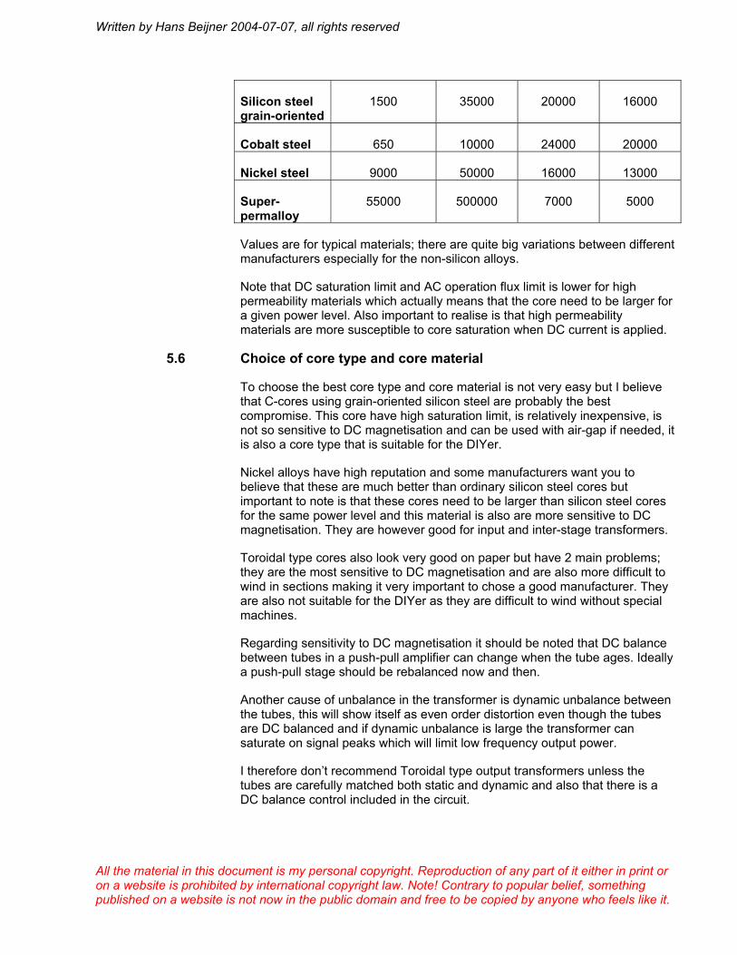
Silicon steel grain-oriented
1500 35000 20000 16000
Cobalt steel 650 10000 24000 20000
Nickel steel 9000 50000 16000 13000
Super- permalloy
55000 500000 7000 5000
Values are for typical materials; there are quite big variations between different manufacturers especially for the non-silicon alloys.
Note that DC saturation limit and AC operation flux limit is lower for high permeability materials which actually means that the core need to be larger for a given power level. Also important to realise is that high permeability materials are more susceptible to core saturation when DC current is applied.
5.6 Choice of core type and core material
To choose the best core type and core material is not very easy but I believe that C-cores using grain-oriented silicon steel are probably the best compromise. This core have high saturation limit, is relatively inexpensive, is not so sensitive to DC magnetisation and can be used with air-gap if needed, it is also a core type that is suitable for the DIYer.
Nickel alloys have high reputation and some manufacturers want you to believe that these are much better than ordinary silicon steel cores but important to note is that these cores need to be larger than silicon steel cores for the same power level and this material is also are more sensitive to DC magnetisation. They are however good for input and inter-stage transformers.
Toroidal type cores also look very good on paper but have 2 main problems; they are the most sensitive to DC magnetisation and are also more difficult to wind in sections making it very important to chose a good manufacturer. They are also not suitable for the DIYer as they are difficult to wind without special machines.
Regarding sensitivity to DC magnetisation it should be noted that DC balance between tubes in a push-pull amplifier can change when the tube ages. Ideally a push-pull stage should be rebalanced now and then.
Another cause of unbalance in the transformer is dynamic unbalance between the tubes, this will show itself as even order distortion even though the tubes are DC balanced and if dynamic unbalance is large the transformer can saturate on signal peaks which will limit low frequency output power.
I therefore don’t recommend Toroidal type output transformers unless the tubes are carefully matched both static and dynamic and also that there is a DC balance control included in the circuit.
Written by Hans Beijner 2004-07-07, all rights reserved
All the material in this document is my personal copyright. Reproduction of any part of it either in print or on a website is prohibited by international copyright law. Note! Contrary to popular belief, something published on a website is not now in the public domain and free to be copied by anyone who feels like it.
5.7 Interleaving
In order to reduce leakage inductance and inter-winding capacitance inter leaving of the windings is used, that is the windings of the primary and secondary are divided into several sections when they are wound on the bobbin. Generally the more sections that are used the coupling improves thereby reducing the leakage inductance. However inter-winding capacitance increase with increased interleaving which make it important to reach a suitable compromise in order to achieve the correct balance between leakage inductance and inter-winding capacitance.
Many output transformers are winded using 5 primary sections and 4 secondary sections; this seems to be the best compromise in many cases. For push-pull transformers it is also common to use 2 parallel sections, (horizontal interleaving) which make it possible to achieve that the sections are exactly equal and have the same winding resistance, the Williamson transformer that is described in section 11 is winded using this method.
6 Reading transformer data sheets
Maybe it is not surprising that companies producing tube amplifier output transformers as every other manufacturer is trying to show their products as favorable as possible. Especially when it comes to output transformers there seem to be no standard way for the conditions at where parameters are measured which means that almost every manufacturer seem to give their product data measured under different conditions.
6.1 General
In general it is important to compare 2 transformers during the same conditions, i.e. primary source impedance, secondary load impedance and power level must be the same for the transformers compared otherwise the comparison is more or less meaningless, it is possible to recalculate values for one set of conditions to others but it is usually difficult as normally not all parameters are given in the datasheet.
Normally it is easier to design a transformer for lower primary impedance and for lower turns ratio so such transformers usually show better performance on paper.
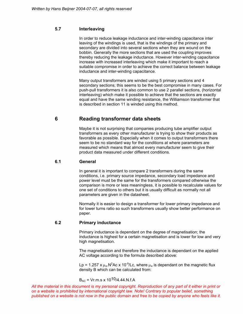
6.2 Primary inductance
Primary inductance is dependant on the degree of magnetisation; the inductance is highest for a certain magnetisation and is lower for low and very high magnetisation.
The magnetisation and therefore the inductance is dependant on the applied AC voltage according to the formula described above:
Lp = 1.257 x µe.N2Ac x 10-9/Lc, where µe is dependant on the magnetic flux density B which can be calculated from:
BAC = Vr.m.s x 1010/4.44.N.f.A

Written by Hans Beijner 2004-07-07, all rights reserved
All the material in this document is my personal copyright. Reproduction of any part of it either in print or on a website is prohibited by international copyright law. Note! Contrary to popular belief, something published on a website is not now in the public domain and free to be copied by anyone who feels like it.
As an example for standard 4% Silicon steel the µe reach a max of ~6000 for a B of ~4000 Gauss but is only 1000 for low B of 10.
Incremental permeability µac characteristics for audio transformer iron lamination with 4% Silicon, H0 is DC magnetising field in Oersteds
6.2.1 Primary inductance in SE transformers
Transformers for SE amplifiers not only have to carry the AC power, they are also subjected to magnetisation by the DC anode current, (in a push-pull amplifier the DC magnetisation from the 2 output tubes cancels). The primary inductance is dependant both on the applied AC voltage and the applied DC current.
Transformers for SE amplifiers are equipped with an air-gap in the magnetic circuit to avoid core saturation by the DC current. The optimum air-gap depends on core material and DC current and it is important to choose a transformer that is specified for the DC current in the actual amplifier. Choosing a transformer designed for much higher DC current than what is needed is false economy, such a transformer is un-necessary large and have less performance than a transformer that is designed for just the needed DC current.
Note the difference between saturating current and operating DC-current, saturating current is max current for complete saturation of the transformer, at this current the core is saturated and µe and Lp approaches 0, note that it is not possible to operate the transformer at this current.
6.2.2 Interpreting manufacturer data for primary inductance
The problem is that some manufacturers give primary inductance values for high primary AC voltages and others give values for very low AC voltages, due to what has been described above the inductance naturally will be lower for low AC voltages than for higher so the values can not be directly compared.

Written by Hans Beijner 2004-07-07, all rights reserved
All the material in this document is my personal copyright. Reproduction of any part of it either in print or on a website is prohibited by international copyright law. Note! Contrary to popular belief, something published on a website is not now in the public domain and free to be copied by anyone who feels like it.
Some manufacturers as for instance Tango give 2 values of primary inductance, one for small AC voltages and on for high AC voltages, as an example the values for Tango FC-120-5 is 160H and 580H where the higher value is indicated as peak inductance, i.e. at a point where is at maximum but the low value is measured with an AC signal of 1mW. Without knowing the core material and the µe /B curve for it, it is very difficult to recalculate this kind of data for other conditions but at least it is possible to compare Tango transformers with other transformers where Lp is measured at peak µe.
6.3 Current imbalance, (for push-pull transformers)
In push-pull transformers the DC magnetisation cancel if the anode current for the 2 tubes are equal, therefore it is important to provide for some sort of means to balance the current if as the case maybe if the tubes are not 100% matched.
Transformers made with EI type lamination usually can withstand some minor current imbalance without air-gap but C-cores and toroidal-type cores are more sensitive for imbalance. Most high quality C-cores are equipped with a minor air-gap to be able to withstand DC-imbalance but toroidal–type cores does not have any air-gap and are therefore much more sensitive to current imbalance than other types.
If there is a current imbalance the primary inductance will be reduced which will be evident as bad low frequency response which also will be worse at low signal level, (when the permeability is lowest). Most high quality manufacturers give a value for max allowed DC-imbalance or give value for the DC-imbalance value where the other parameters are measured.
6.4 Max power or lowest useable frequency
The maximum output power is usually given at a certain frequency where the power has been reduced by 3dB, this is mostly dependant on the primary inductance Lp at the magnetisation given by the power level, if the power level is decreased the inductance is increased but as it is not possible to know at what level of magnetisation the measurements of Lp are made it is difficult to compare data from different manufacturers.
Some manufacturers like Tango instead specifies max power at a certain level of distortion.
6.5 Frequency range or highest useable frequency
The high frequency limit of a transformer is dependant on 2 parameters, leakage inductance and winding capacitance, it is unusual to find values for both these parameters in data sheet which is a pity as it is difficult to compare transformers without knowing both parameters. It is not enough that leakage inductance is low, it also need to be balanced to the capacitance value otherwise the frequency response for high frequencies will not be optimal. The leakage inductance and winding capacitance form a low pass filter and the relation between these 2 parameters decide the response of this filter, for optimum result the filter should ideally have a filter Q of ~0.7, (Butterworth response).

Written by Hans Beijner 2004-07-07, all rights reserved
All the material in this document is my personal copyright. Reproduction of any part of it either in print or on a website is prohibited by international copyright law. Note! Contrary to popular belief, something published on a website is not now in the public domain and free to be copied by anyone who feels like it.
If the leakage inductance and winding capacitance has the wrong relation the high frequency limit can look good on paper but the practical result will not be optimal.
Too high leakage inductance automatically means that the winding capacitance is too low and the result is a high frequency –3dB point that is very high but the attenuation above the –3dB point increases very quickly, this means also that the phase response change quickly and it will be difficult to make the amplifier stable when feedback is used, in some cases there can even be so that the amplitude is increasing at high frequencies and then suddenly drops rapidly.
Too low leakage inductance automatically means that the winding capacitance is too high and the result is that the attenuation at high frequencies is reduced more gradually with an un-necessary too low high –3dB point.
6.6 Insertion loss
Insertion loss can be measured in many different ways that differs between manufacturers, some transformers can be connected in such a way that loss is less dependent on load impedance, (Lundahl); normally loss is lowest to the output with the highest impedance.
Manufacturer Tango Plitron Lundahl ASV
Lp, max At max µe At 250V, 60Hz, (max µe?)
At max power At 230V, 50Hz, (max µe?)
Lp low level At 1mW No No No
Lp at current imbalance
Yes, actual DC current value is depending on transformer type
No No No
Bandwidth Yes, at low level, can be used to calculate value of Lsc
Yes, but no conditions given
Yes, but no conditions given
Yes, but no conditions given
Lsc No Yes Yes Yes
Max power condition
Distortion < 1% 3rd order at 30Hz
? At -3dB / 30Hz ?
Low frequency limit, conditions
At 4Vp-p, Rg = 0.5Zp
? At full power only
At 1mW, Rg unknown

Written by Hans Beijner 2004-07-07, all rights reserved
All the material in this document is my personal copyright. Reproduction of any part of it either in print or on a website is prohibited by international copyright law. Note! Contrary to popular belief, something published on a website is not now in the public domain and free to be copied by anyone who feels like it.
Loss To 16 ohm output
? ? ?
7 Designing you own output transformer
Designing you own output transformer can be a rewarding experience but I must warn you that it also means a lot of hard manual work, if you value your spare time in money it is probably a waste of money and time to design your own transformer. It takes quite long time to wind a transformer using DIY equipment, the winding machines that commercial manufacturers uses make the work much easier.
7.1 Choice of tools
What is needed is basically a hand cranked hand drill that you set up horizontally in a vice. You will also need a square piece of wood that fits snugly inside the bobbin. Drill a hole trough the centre of the wood piece and mount a long screw trough the hole secured with washers and a nut. The end of the screw is placed in the chuck of the drill.
It is possible to count the turns by hand but it is very easy to make a mistake so it therefore pays off to set up some sort of automatic rev counter if it can be arranged.
7.2 Choice of materials
The most important material is of course the core, which could be an EI type core or a C-core. Old power transformers can be used, the metal in these transformers are usually plain silicon iron which gives acceptable results, see information about the Williamson transformer described in chapter that was design using ordinary silicon iron. The best EI cores have thin laminations, preferably 0.35mm or less. Even better are C-type cores and they are not so difficult to find these days.
Enamelled copper-wire is not difficult to source but is getting more expensive.
Insulation paper can be difficult to get hold of but graphical and artist shops have waxed paper that is good as insulation. Insulation between layers in the same side (primary or secondary) should be paper with typical thickness 0.05mm. Insulation between primary and secondary sections should be thicker in order to withstand the isolation typically 0.3mm is enough. On of the best isolation paper that exists is the one found in old paper capacitors but these are hard to found nowadays.
7.3 Initial dimensioning
First choice is if the transformer should be used in a SE amplifier or push-pull. In SE amplifier the core is subjected to DC magnetisation and therefore need an air-gap and a larger core than a push-pull transformer.
Some initial data is needed in order to start calculations.
Written by Hans Beijner 2004-07-07, all rights reserved
All the material in this document is my personal copyright. Reproduction of any part of it either in print or on a website is prohibited by international copyright law. Note! Contrary to popular belief, something published on a website is not now in the public domain and free to be copied by anyone who feels like it.
• Primary load impedance, Zp
• Secondary impedance, Zs
• AC Power, P
• Acceptable distortion level
• Lowest frequency at full power, Fmin
• Highest frequency at –3dB, Fhigh
• Max DC current
Choose reasonable values for these parameters, it is unlikely that you will be able to make a transformer that is equal to the very best on the market but I know that it is possible to make very good transformers as DIY.
My recommendation is to start design the transformer for power level, low frequency limit, distortion and DC current and then calculate what the high frequency response will be. If you are not satisfied with the high frequency performance you need to compromise by allowing a higher Fmin or limit the max power.
Please note the importance of distortion that normally always determines the primary turns and therefore the transformer size.

Written by Hans Beijner 2004-07-07, all rights reserved
All the material in this document is my personal copyright. Reproduction of any part of it either in print or on a website is prohibited by international copyright law. Note! Contrary to popular belief, something published on a website is not now in the public domain and free to be copied by anyone who feels like it.
8 Units used in magnetic formulas
Designation Unit Description Lp H Primary winding inductance Llp H Primary leakage
inductance Ls H Secondary winding
inductance Lls H Secondary leakage
inductance Rp Ohm Primary resistance Rg Ohm Primary generator
impedance Rs Ohm Secondary resistance Rl Ohm Secondary load impedance Zp Ohm Primary load impedance =
a² x Rl Np Dimensionless Primary turns Ns Dimensionless Secondary turns µ Dimensionless Permeability µ0 Permeability for air µe Dimensionless Effective permeability Ac mm² Core Area S A/mm² Current density MPL mm Magnetic path length
trough core La mm Magnetic path length
trough air, air-gap MLT m Mean Length per Turn
B Gauss Magnetic flux density
H Oersteds Magnetic field strength
Φ Maxwell Magnetic flux
F Hz Frequency
VpAC V Primary AC voltage
VsAC V Secondary AC voltage
Xm Ohm Primary reactance
α Dimensionless Turns ratio, Np/Ns

Written by Hans Beijner 2004-07-07, all rights reserved
All the material in this document is my personal copyright. Reproduction of any part of it either in print or on a website is prohibited by international copyright law. Note! Contrary to popular belief, something published on a website is not now in the public domain and free to be copied by anyone who feels like it.
9 Design of push-pull transformers, (no air-gap)
Notes: Distortion level and Fmin give value of primary inductance; usually distortion is of more importance.
9.1 Needed in-data
Primary load impedance, Zp
Secondary impedance, Zs
Power, P
Allowable distortion level, %
Lowest frequency at full power –3dB, Fmin
Highest frequency at –3dB, Fhigh
Bmax for chosen core material
9.2 Calculate transformation ratio α
ZsZp
=α
9.3 Calculate required core area
min*90014000 F
PAc = mm², for Bmax =14000 Gauss, for other degree of
magnetisation use max
14000*14000 BAcAc =
9.4 Calculate required min primary inductance Lp
Calculate( )( )2
2
*21*2*1'αα
RRRRparR
+= , where RpRgR +=1 , and RsRlR +=2
As a starting point assume RlRpRs 05.02 ≈=α
, this gives a copper efficiency of
91%
Calculate required fparRLpπ2
'=
9.5 Calculating allowable leakage inductance
Calculate 2*21' αRRseR +=

Written by Hans Beijner 2004-07-07, all rights reserved
All the material in this document is my personal copyright. Reproduction of any part of it either in print or on a website is prohibited by international copyright law. Note! Contrary to popular belief, something published on a website is not now in the public domain and free to be copied by anyone who feels like it.
FhighseRLlp
**2'
π=
9.6 Check for distortion at a given frequency f
Assume Bm = 5000
Calculate AcfBac
VrmsNp***44.4
10* 10
=
CalculateLc
AcNeLpd92 10****257.1 −
=µ
; use µe from table in 5.5
Calculate LpdfXm ***2 π=
Calculate harmonic distortion from:
−
=
XmparR
XmparR
IfIh
EfEh
*4'1*'*
IfIh
Values for 4% FeSi
9.7 Calculate secondary number of turns
ZpRlNpNs *=
9.8 Check that the wire fits the given space
Calculate the Mean Length per Turn in meter
Calculate total length for primary and secondary
MLTNpLtotp *=
MLTNsLtots *=
Bm Ih 3rd order Ih 5th order 100 4 1.0 500 7 1.5
1000 9 2.0 3000 15 2.5 5000 20 3.0
10000 30 5.0

Written by Hans Beijner 2004-07-07, all rights reserved
All the material in this document is my personal copyright. Reproduction of any part of it either in print or on a website is prohibited by international copyright law. Note! Contrary to popular belief, something published on a website is not now in the public domain and free to be copied by anyone who feels like it.
Calculate wire area for primary wire RpLtotpAp *017.0= mm² Calculate wire
area for secondary wire RsLtotsAs *017.0= mm²
Select wire for primary and secondary windings; allow 3A/mm² for ordinary enamelled copper wire, if thick enough wire doesn’t fit on the available space a new calculation has to be started from chapter 9.6
Wire diameter is calculated from π
4*AD =
Calculate the number of primary and secondary layers
Calculate if the wire fits in the available space including insulation
9.9 Check value of leakage inductance
Formula for interleaved primary and secondary windings
( )( )92
2
10****2***4.0bn
atnMLTNpLlp +=
Physical dimensions related to calculation of leakage inductance
Where n is the number of section interfaces, as an example a transformer having 5 primary sections and 4 secondary sections have 8 section interfaces.
a is the total thickness of the coils in mm
t is the thickness of isolation between layers in mm
b is the width of the winding in mm

Written by Hans Beijner 2004-07-07, all rights reserved
All the material in this document is my personal copyright. Reproduction of any part of it either in print or on a website is prohibited by international copyright law. Note! Contrary to popular belief, something published on a website is not now in the public domain and free to be copied by anyone who feels like it.
10 Design of SE transformers, (with air-gap)
Designing transformers for Single Ended amplifiers where the core is subjected to both DC and AC magnetisation is quite a bit more difficult than for push-pull transformers.
The first choice is the degree of DC magnetisation, most common is to use a value that is half of Bmax, which is typically ~14000 - 16000 for silicon iron, this means that max AC magnetisation will be half of this, or 7000 – 8000 Gauss for silicon iron
10.1 Needed in-data
Primary load impedance, Zp
Secondary impedance, Zs
AC Power, P
Lowest frequency at full power, Fmin
Highest frequency at –3dB, Fhigh
DC current
10.2 Calculate required core area
min*127014000 F
PAc = mm², for Bmax =14000 Gauss, for other degree of
magnetisation use max
14000*14000 BAcAc =
10.3 Calculate required min primary inductance Lp
Calculate ( )( )2
2
*21*2*1'αα
RRRRparR
+= , where RpRgR +=1 , and RsRlR +=2
As a starting point assume RlRpRs 05.02 ≈=α
, this gives a copper efficiency of
91%
Calculate required fparRLpπ2
'=

Written by Hans Beijner 2004-07-07, all rights reserved
All the material in this document is my personal copyright. Reproduction of any part of it either in print or on a website is prohibited by international copyright law. Note! Contrary to popular belief, something published on a website is not now in the public domain and free to be copied by anyone who feels like it.
10.4 Determine air-gap
There is a particular air-gap for which the incremental or AC inductance reaches a maximum when the core material and dimensions, the number of turns, and the DC magnetising current are fixed. As the DC magnetising current is increased, the optimum air-gap becomes longer and the corresponding incremental AC inductance less. The behaviour in a typical case is shown by the figure.
This best length of air-gap can be obtained by plotting curves of VIL 2*
as a
function of MPL
IN * for various percentage air-gap lengths, as shown by the
figure below, where L is the incremental AC inductance, I is the direct current, V the volume of the core, N the number of turns, and MPL the length of the magnetic circuit.
Written by Hans Beijner 2004-07-07, all rights reserved
All the material in this document is my personal copyright. Reproduction of any part of it either in print or on a website is prohibited by international copyright law. Note! Contrary to popular belief, something published on a website is not now in the public domain and free to be copied by anyone who feels like it.
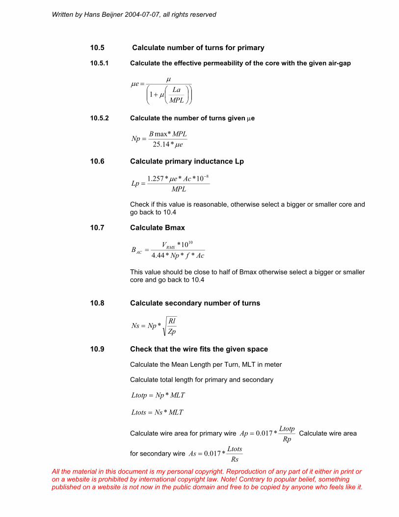
10.5 Calculate number of turns for primary
10.5.1 Calculate the effective permeability of the core with the given air-gap
+
=
MPLLa
eµ
µµ1
10.5.2 Calculate the number of turns given µe
eMPLBNpµ*14.25
max*=
10.6 Calculate primary inductance Lp
MPLAceLp
810***257.1 −
=µ
Check if this value is reasonable, otherwise select a bigger or smaller core and go back to 10.4
10.7 Calculate Bmax
AcfNpV
B RMSAC ***44.4
10* 10
=
This value should be close to half of Bmax otherwise select a bigger or smaller core and go back to 10.4
10.8 Calculate secondary number of turns
ZpRlNpNs *=
10.9 Check that the wire fits the given space
Calculate the Mean Length per Turn, MLT in meter
Calculate total length for primary and secondary
MLTNpLtotp *=
MLTNsLtots *=
Calculate wire area for primary wire RpLtotpAp *017.0= Calculate wire area
for secondary wire RsLtotsAs *017.0=

Written by Hans Beijner 2004-07-07, all rights reserved
All the material in this document is my personal copyright. Reproduction of any part of it either in print or on a website is prohibited by international copyright law. Note! Contrary to popular belief, something published on a website is not now in the public domain and free to be copied by anyone who feels like it.
Select wire for primary and secondary windings allow 3A/mm² for ordinary enamelled copper wire if thick enough wire doesn’t fit on the available space a new calculation has to be started from chapter 10.4
Wire diameter is calculated from π
4*AD =
Calculate the number of primary and secondary layers
Calculate if the wire fits in the available space including insulation, a good transformer has a fill factor of 85% that is the windings take up 85% of the available space
10.10 Calculating allowable leakage inductance
Calculate 2*21' αRRseR +=
FhighseRLscp
**2'
π= H
10.11 Check value of leakage inductance
Note this formula is for a transformer with interleaved primary and secondary windings.
( )( )92
2
10****2***4.0bn
acnMLTNpLlp += , all dimensions in mm
Where n is number of section interfaces, as an example a transformer having 5 primary sections and 4 secondary section have 8 section interfaces.
a is the total thickness of the coils
c is the thickness of isolation between layers
b is the width of the winding
11 The Williamson transformer
The Williamson amplifier designed by D.T.N Williamson is a milestone in audio amplifier design. Williamson was employed by The GE Valve Company as an engineer and he designed the amplifier partly because of his own interest but also as a way for the GE Valve Company to promote their new KT66 Beam tetrode.
The unique thing about the Williamson amplifier is that it was the first time an amplifier was designed using what could be seen even today as modern design methods. Triode coupled beam tetrodes where used together with a well designed input and driver stage, feedback was also applied in a controlled manner achieving a bandwidth of 20 – 20 kHz within 0.2dB and a distortion level of <0.1% at up to 15W output power.

Written by Hans Beijner 2004-07-07, all rights reserved
All the material in this document is my personal copyright. Reproduction of any part of it either in print or on a website is prohibited by international copyright law. Note! Contrary to popular belief, something published on a website is not now in the public domain and free to be copied by anyone who feels like it.
The Williamson amplifier has been subjected to criticism over the years but in most cases this is due to misunderstanding of the original circuit function or because many people have modified the original circuit in order to “improve” it.
The most common “improvements” are using an output transformer other than the one specified, ultra-linear coupling of the output stage, change of tubes in the driver stage from original L63’s to other tubes without modification of other circuit values or change of output tubes from original KT66’s to 807’s or other tube. Most of these changes don’t offer any improvement of the original design; on the contrary most of these modifications will increase distortion, reduce bandwidth or introduce instability compared to the original circuit.
The Williamson amplifier in its original form with the specified circuit values, tubes and output transformer is still a very good amplifier even when compared to newer designs be it tube or transistor equipped.
The only basic thing I think could be improved in the basic design is stability at low and high frequencies, in the original Williamson amplifier the phase margin is quite low ~30 degrees which is acceptable but I feel that a higher degree of phase margin is desired and is not difficult to achieve by subtle modifications in a Williamson amplifier without affecting any other parameters.
The transformer specified by Williamson was said to be designed in a new way compared to many others, that is not quite thru, there had been other companies and designers thinking about the same idea and the basic ideas are for instance described in “Radio engineers handbook” by F.E. Terman with references to other works as early as 1928. However it is mainly not the details that are imaginative in the Williamson amplifier but the whole concept.
One however rather unique design concept with the transformer specified by Williamson is that it was designed to a certain distortion level, this was not usual at the time but instead output transformers where normally designed to pass a certain power level at a certain low frequency limit.
As can be seen by the formulas in chapter 9 a transformer can either be designed for low frequency limit or for a specified degree of distortion, either of these parameters determine the number of primary turns and the core size. In the majority of cases designing for low distortion determine the size of the transformer and not the low frequency limit, this is something that even today is not recognised by most transformer manufacturers, the only exception I really have found is Tango.
So, the Williamson transformer is big mainly not because it was designed a long time ago but because it was designed for low distortion!
The transformer itself is wound on a EI core similar to EI125 e.g. the transformer is 125mm wide, the thickness of the core was 1.75” ~44.5mm. The material is super Silcor which is actually ordinary silicon iron with 4% silicon, the used laminations where 0.01” thick.

Written by Hans Beijner 2004-07-07, all rights reserved
All the material in this document is my personal copyright. Reproduction of any part of it either in print or on a website is prohibited by international copyright law. Note! Contrary to popular belief, something published on a website is not now in the public domain and free to be copied by anyone who feels like it.
The transformer is winded in 2 parts side by side, each part consist of 5 primary sections and 4 secondary sections. Each primary section consists of 5 layers with 88 turns of 0.25mm enamelled copper wire in each layer. Each secondary section consists of 2 layers with 29 turns of 0.9mm enamelled copper wire in each layer. Each layer is insulated with paper 0.05mm thick and between primary and secondary sections are 3 layers of paper 0.13mm thick.
The transformer has the following data:
Primary inductance 100H at small signal
Leakage inductance <22mH
Distortion at 30Hz and 15W <1%
Bandwidth at 15W –3dB 30 Hz to 60 kHz
This data is still comparable with data of many transformers of today; only the more expensive models from Tango, Tamura, Lundahl and some others show significantly better data.
12 References
It is not easy to find literature containing all needed formulas for transformer calculations; I have therefore collected information from various sources, some of the most important are mentioned here:
Private unpublished papers by Olof Beijner, (my father)
“Radio Engineers Handbook” by F.E. Terman
“Reference Data For radio Engineers” published by ITT
“The Williamson Amplifier” article series from Wireless World 1947