Embed Size (px)
Citation preview
Monte Carlo Calculation of the Energy Deposition in the Transformational Challenge Reactor
A. Talamo1a, A. Bergerona, M. Subhasisha, S.N. P. Vegendlaa, F. Heideta
B. Adeb, B.R. Betzlerb
a)Argonne National Laboratory, 9700 South Cass Avenue, Argonne, IL 60439, USAb)Oak Ridge National Laboratory, P.O. Box 2008, Oak Ridge, TN 37831-6170, USA
INTRODUCTION
Accurate calculation of the recoverable (non-
neutrinos) energy deposited in a nuclear facility requires
the estimate of: the kinetic energy of fission fragments, the
kinetic energy of prompt and delayed neutrons, the kinetic
energy of prompt and delayed gammas, and the energy
released by delayed betas. The MCNP Monte Carlo code
[1] does not have the capability to tally the delayed
gammas and betas energy deposition, therefore the
calculation must rely on a few approximations, as
discussed in detail in the next Section. The Serpent Monte
Carlo code [2] evaluates the energy deposition in a more
sophisticated approach that aims at reducing
approximations and relies on the Kinetic Energy Released
per unit Mass (KERMA) factors rather than the Q-value
used by MCNP, as discussed in the Section after next. This
summary aims at comparing the energy deposition results
obtained by the aforementioned Monte Carlo codes for
designing the Transformational Challenge Reactor (TCR),
a microreactor designed, built, and operated using a rapid
advanced manufacturing approach [3] and illustrated in
Fig. 1 .
MCNP CALCULATION METHODOLOGY
The MCNP code can calculate the energy deposition
by two separate criticality (k-code) coupled (neutron and
photon transport) simulations [4, 5]. In the first simulation,
three different tallies are used:
1. the F6 neutron tally (F6n) scores the kinetic energy of
neutrons and fission products in all cells (with fission
products kinetic energy contributing only to the fuel
cells);
2. the F6 photon tally (F6p) scores the energy from
fission prompt gammas and gammas released from
non-fission (e.g., capture) neutron incident reactions
in all cells;
3. the F7 neutron (F7n) tally scores the kinetic energy of
neutrons, fission products, and prompt gammas
deposited in the fuel cells.
The third tally is used to estimate the energy released
from the beta decay of fission products. More precisely, it
is assumed that the latter parameter is equal to 6.5
MeV/fission (the U-235 value) and follows the spatial
distribution of the F7n neutron tally. In the second MCNP
simulation, only one F6 photon tally is used (F6pprompt).
This tally scores the photon energy deposition in all cells
from fission prompt gammas. In the second simulation, all
gammas coming from non-fission neutron incident
reactions are suppressed by using the following MCNP
card [6]:
pikmt 92234 1 18001 1
92235 1 18001 1
92236 1 18001 1
92238 1 18001 1
With the above card only prompt gammas coming
from fission reactions are produced and tracked. In
criticality mode, MCNP6.2 does not model the production
of delayed gammas from fission reactions. Consequently,
the delayed gamma energy is assumed to be equal to 6.33
MeV/fission (the U-235 value) and the delayed gamma
spatial distribution is assumed to follow that of prompt
gammas, as given by the F6pprompt tally of the second
MCNP simulation. Finally, the power (in Watt units)
deposited in a (U-235) fuel cell volume can be calculated
by Eq. (1).
𝑝𝑜𝑤𝑒𝑟 =
= (𝜈𝐹6𝑛
𝑘𝑒𝑓𝑓
+ 𝜈𝐹6𝑝
𝑘𝑒𝑓𝑓
+ 6.5𝐹7𝑛
∑ 𝐹7𝑛𝑓𝑢𝑒𝑙
+ 6.33 𝐹6𝑝𝑝𝑟𝑜𝑚𝑝𝑡
∑ 𝐹6𝑝𝑝𝑟𝑜𝑚𝑝𝑡𝑎𝑙𝑙
)𝑃
𝑄 =
= 𝑛𝑒𝑢𝑡𝑟𝑜𝑛𝑠 𝑎𝑛𝑑 𝑓𝑖𝑠𝑠𝑖𝑜𝑛 𝑝𝑟𝑜𝑑𝑢𝑐𝑡𝑠 𝑘𝑖𝑛𝑒𝑡𝑖𝑐 𝑒𝑛𝑒𝑟𝑔𝑦+ 𝑝𝑟𝑜𝑚𝑝𝑡 𝑔𝑎𝑚𝑚𝑎𝑠 𝑒𝑛𝑒𝑟𝑔𝑦 + 𝑏𝑒𝑡𝑎 𝑑𝑒𝑐𝑎𝑦 𝑒𝑛𝑒𝑟𝑔𝑦+ 𝑑𝑒𝑙𝑎𝑦𝑒𝑑 𝑔𝑎𝑚𝑚𝑎𝑠 𝑒𝑛𝑒𝑟𝑔𝑦 (1)
In the above equation, is the number of fission
neutrons (2.438), P is the system power (e.g., 3 MW for the
Transformational Challenge Reactor [7]), the fuel and all
are summatories over the fuel cells and all cells,
https://dx.doi.org/10.13182/T123-33031
1429
*The submitted manuscript has been created by UChicago Argonne LLC, Operator of Argonne National Laboratory ("Argonne"). Argonne, a U.S. Departmentof Energy Office of Science laboratory, is operated under Contract No. DE-AC02-06CH11357. The U.S. Government retains for itself, and others acting on
its behalf, a paid-up nonexclusive, irrevocable worldwide license in said article to reproduce, prepare derivative works, distribute copies to the public, and
perform publicly and display publicly, by or on behalf of the Government.
Transactions of the American Nuclear Society, Vol. 123, 2020 ANS Virtual Winter Meeting, November 16-19, 2020
Transformational Challenge Reactor–Current Developments–I
respectively, and Q is the fuel Q-value (in MeV units). For
U-235, the latter can be calculated by Eq. (2).
𝑄 = 𝜈∑ 𝐹6𝑛𝑎𝑙𝑙
𝑘𝑒𝑓𝑓
+ 𝜈∑ 𝐹6𝑝𝑎𝑙𝑙
𝑘𝑒𝑓𝑓
+ 6.5 + 6.33 =
= 172.41 + 17.41 + 6.5 + 6.33 = 202.65 𝑀𝑒𝑉 (2)
All the tallies used in the MCNP simulations are
integrated over the cell volumes using the sd card with all
entries set to one. In Equation 1, the third addend on the
right side is equal to zero if the cell contains no fuel. The
beta decay energy is confined in the fuel cells because
fission products travel less than 10 m. Consequently, the
power deposition in a cell that does not contain any fuel has
been calculated by Eq. (3).
𝑝𝑜𝑤𝑒𝑟 = (𝜈𝐹6𝑛
𝑘𝑒𝑓𝑓+ 𝜈
𝐹6𝑝
𝑘𝑒𝑓𝑓+ 6.33
𝐹6𝑝𝑝𝑟𝑜𝑚𝑝𝑡
∑ 𝐹6𝑝𝑝𝑟𝑜𝑚𝑝𝑡𝑎𝑙𝑙)
𝑃
𝑄 (3)
SERPENT CALCULATION METHODOLOGY
The Serpent most accurate methodology [8] to
calculate the energy deposition assumes that the energy
deposited per fission reaction f for (fissioned) nuclide i
(𝐸𝑖,𝑓) is given by Eq. 4.
𝐸𝑖,𝑓 = 𝐾𝐸̅̅ ̅̅𝑖𝐹𝑃 + 𝐸𝑖
𝛽 (4)
In Eq. 4, the first term on the right hand side 𝐾𝐸̅̅ ̅̅𝑖𝐹𝑃 is
the average (prompt) kinetic energy of fission products and
the second one 𝐸𝑖𝛽
is the energy of delayed betas for
nuclide i. The neutron and prompt gamma heating for
reactions other than fission is calculated using KERMA
factors. More precisely, the energy deposited per non-
fission reaction x for nuclide i (𝐸𝑖,𝑗) is given by Eq. 5.
𝐸𝑖,𝑥 = 𝜌𝑖𝑘𝑖,𝑥(𝐸)Φ(𝐸) (5)
In Eq. 5, 𝜌𝑖 is the atomic density of nuclide i, 𝑘𝑖,𝑥(𝐸)
is the KERMA factor for non-fission reaction x and nuclide
i at incident neutron/prompt photon energy E, and Φ(𝐸) is
the scalar neutron/prompt photon flux for neutron/prompt
photon energy E. With the direct method, NJOY calculates
the KERMA factor 𝑘𝑖,𝑥(𝐸) according to Eq. (6).
𝑘𝑖,𝑥(𝐸) = ∑ 𝐾𝐸̅̅ ̅̅𝑖,𝑥𝑚
𝑚
𝜎𝑖,𝑥(𝐸) (6)
In Eq. 6, 𝐾𝐸̅̅ ̅̅𝑖,𝑥𝑚 is the average kinetic energy of the m
secondary particle born in the (i,x) reaction, 𝜎𝑖,𝑥(𝐸) is the
microscopic cross section of the (i,x) reaction at incident
neutron/prompt photon energy E, and the summatory [8] is
carried out over all charged products of the (i,x) reaction
including the recoil nucleus i. Consequently, NJOY
computes the KERMA factor 𝑘𝑖,𝑥(𝐸) according to Eq. 7.
𝑘𝑖,𝑥(𝐸) = (𝐸 + 𝑄𝑖,𝑥 − 𝐾𝐸̅̅ ̅̅𝑖,𝑥𝑛 − 𝐾𝐸̅̅ ̅̅
𝑖,𝑥𝑝𝑝
)𝜎𝑖,𝑥(𝐸) (7)
In Eq. 7, E is the incident neutron/prompt photon energy,
𝑄𝑖,𝑥is the mass difference Q-value for target nucleus i and
reaction x, 𝐾𝐸̅̅ ̅̅𝑖,𝑥𝑛 is the average kinetic energy of secondary
neutrons for target nucleus i and reaction x, and 𝐾𝐸̅̅ ̅̅𝑖,𝑥𝑝𝑝
is the
average kinetic energy of secondary (prompt) photons for
target nucleus i and reaction x. In summary, Serpent uses
Eq. 5 for calculating the energy deposition from a non-
fission reaction x and Eq. 4 for calculating the energy
deposition from a fission reaction f. In Serpent, the energy
deposited by delayed gammas (which is not included in
Eqs. 4 and 5) is added to the energy deposited by prompt
gammas using the scaling factor f defined in Eq. 8.
𝑓 =�̅�𝑖,𝑓
𝑑𝑝+ �̅�𝑖,𝑓
𝑝𝑝
�̅�𝑖,𝑓𝑝𝑝 (8)
In Eq. 8, �̅�𝑖,𝑓𝑑𝑝
and �̅�𝑖,𝑓𝑛𝑝
are the delayed and prompt
gamma energy released per fission reaction for nuclide i,
respectively. These data can be retrieved in the MT458
section of ENDF nuclear data libraries [8].
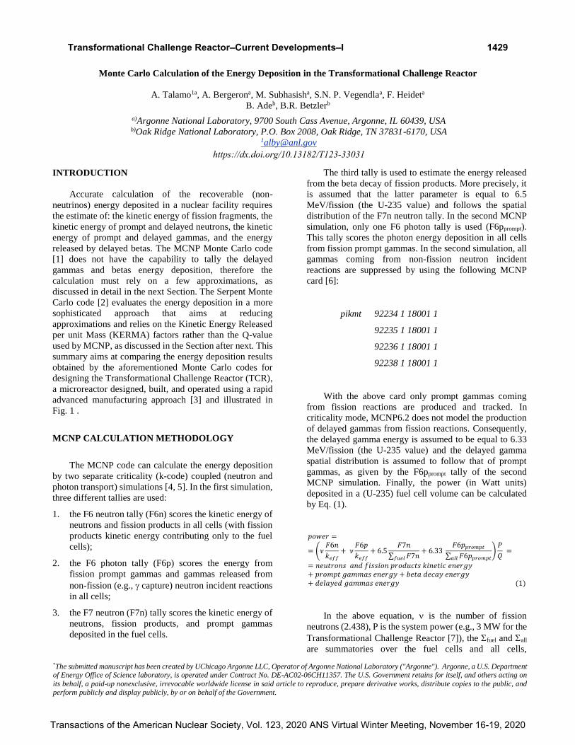
Fig. 1. Overview of the Transformational Challenge
Reactor.
1430
Transactions of the American Nuclear Society, Vol. 123, 2020 ANS Virtual Winter Meeting, November 16-19, 2020
Transformational Challenge Reactor–Current Developments–I
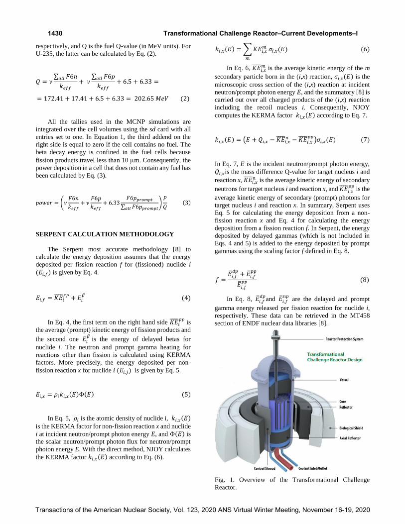
TCR ANALYSES
The MCNP model of the TCR has been prepared at
ORNL and is illustrated in Figs. 2 and 3. In Figs. 2 and 3,
the colors indicate the following materials: stainless steel
(green), air (yellow), silicon carbide (blue), yttrium hydride
(cyan), uranium nitride TRISO particles dispersed in
silicon carbide (red), stainless steel and helium (purple).
After this summary the model has been heavily updated to
include a more detailed description of the reactor
components and to better optimize the design.
Fig. 2. Vertical section of the Monte Carlo model of the
TCR.
The MCNP model of the TCR created at ORNL has
been automatically converted to a Serpent model by a
Python script developed at ANL. The Python script ensures
that all geometry and materials specifications are the same
in both Monte Carlo codes inputs. Serpent version 2.1.32
and MCNP version 6.2 have been used with the ENDF/B-
VIII.0 and ENDF/B-VII.1. Only the ENDF/B-VIII.0
nuclear data library contains S(,) data for hydrogen and
yttrium bound in yttrium hydride. Serpent has the
capability to read and use the ACE files shipped with
MCNP. When both Monte Carlo code use the same ACE
files based on the ENDF/B-VIII.0 nuclear data library (as
shipped with MCNP version 6.2), the effective
multiplication factor keff calculated by Serpent and MCNP
is 1.03612±2E-5 and 1.03632±5E-5, respectively.
Fig. 3. Horizontal section of the Monte Carlo model of the
TCR in the fuel zone.
As discussed in the previous Section, the calculation
of the energy deposition by Serpent requires enhanced
ACE files with additional data. These enhanced ACE files
have been provided by the Serpent development team for
the ENDF/B-VII.1 nuclear data library, which does not
have any S(,) data for hydrogen and yttrium bound in
yttrium hydride. Consequently, the Serpent simulation
calculating the energy deposition is based on the ENDF/B-
VII.1 enhanced ACE files from Serpent development team
and the S(,) data from the ENDF/B-VIII.0 library
shipped with MCNP version 6.2. Similarly, the MCNP
simulation calculating the energy deposition is based on the
ENDF/B-VII.1 ACE files and the S(,) data from the
ENDF/B-VIII.0 library, with all data coming from the files
shipped with MCNP version 6.2.
Figure 4 shows the total energy deposition, including
both neutron and gamma contributions, calculated by
Serpent in the first fuel layer (located at the bottom of the
core) and the fourth fuel layer (located in the middle of the
core). The fuel zone of the core is segmented in eight axial
layers. Obviously, the energy deposition peaks at the center
of the core and drops at the central hexagon. The latter does
not contain any fuel since it allocates the channel for the
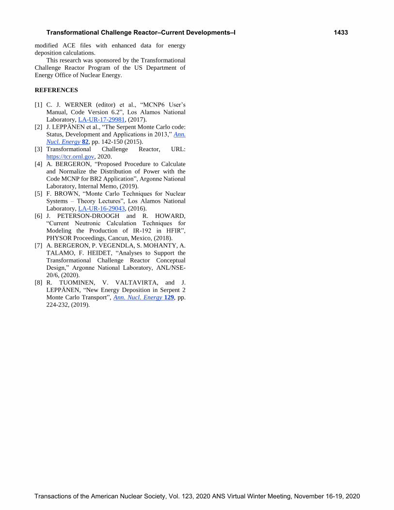
central safety rod. The relative difference between Serpent
and MCNP results is shown in Fig. 5 and is generally below
0.5 and 1% for neutrons and photons in the fuel zone (blue
hexagons in Fig. 5). In other zones (non-blue hexagons in
Fig. 5), this difference increases up to a few percent.
1431
Transactions of the American Nuclear Society, Vol. 123, 2020 ANS Virtual Winter Meeting, November 16-19, 2020
Transformational Challenge Reactor–Current Developments–I
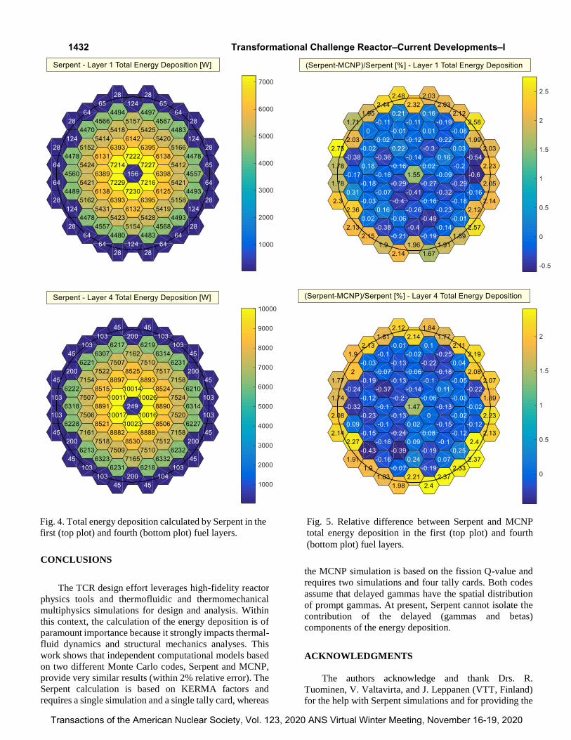
Fig. 1. Total energy deposition calculated by Serpent in the
first (top plot) and fourth (bottom plot) fuel layers.
CONCLUSIONS
The TCR design effort leverages high-fidelity reactor
physics tools and thermofluidic and thermomechanical
multiphysics simulations for design and analysis. Within
this context, the calculation of the energy deposition is of
paramount importance because it strongly impacts thermal-
fluid dynamics and structural mechanics analyses. This
work shows that independent computational models based
on two different Monte Carlo codes, Serpent and MCNP,
provide very similar results (within 2% relative error). The
Serpent calculation is based on KERMA factors and
requires a single simulation and a single tally card, whereas
the MCNP simulation is based on the fission Q-value and
requires two simulations and four tally cards. Both codes
assume that delayed gammas have the spatial distribution
of prompt gammas. At present, Serpent cannot isolate the
contribution of the delayed (gammas and betas)
components of the energy deposition.
ACKNOWLEDGMENTS
The authors acknowledge and thank Drs. R.
Tuominen, V. Valtavirta, and J. Leppanen (VTT, Finland)
for the help with Serpent simulations and for providing the
Fig. 4. Total energy deposition calculated by Serpent in the
first (top plot) and fourth (bottom plot) fuel layers.
Fig. 5. Relative difference between Serpent and MCNP
total energy deposition in the first (top plot) and fourth
(bottom plot) fuel layers.
1432
Transactions of the American Nuclear Society, Vol. 123, 2020 ANS Virtual Winter Meeting, November 16-19, 2020
Transformational Challenge Reactor–Current Developments–I
modified ACE files with enhanced data for energy
deposition calculations.
This research was sponsored by the Transformational
Challenge Reactor Program of the US Department of
Energy Office of Nuclear Energy.
REFERENCES
[1] C. J. WERNER (editor) et al., “MCNP6 User’s
Manual, Code Version 6.2”, Los Alamos National
Laboratory, LA-UR-17-29981, (2017).
[2] J. LEPPÄNEN et al., “The Serpent Monte Carlo code:
Status, Development and Applications in 2013,” Ann.
Nucl. Energy 82, pp. 142-150 (2015).
[3] Transformational Challenge Reactor, URL:
https://tcr.ornl.gov, 2020.
[4] A. BERGERON, “Proposed Procedure to Calculate
and Normalize the Distribution of Power with the
Code MCNP for BR2 Application”, Argonne National
Laboratory, Internal Memo, (2019).
[5] F. BROWN, “Monte Carlo Techniques for Nuclear
Systems – Theory Lectures”, Los Alamos National
Laboratory, LA-UR-16-29043, (2016).
[6] J. PETERSON-DROOGH and R. HOWARD,
“Current Neutronic Calculation Techniques for
Modeling the Production of IR-192 in HFIR”,
PHYSOR Proceedings, Cancun, Mexico, (2018).
[7] A. BERGERON, P. VEGENDLA, S. MOHANTY, A.
TALAMO, F. HEIDET, “Analyses to Support the
Transformational Challenge Reactor Conceptual
Design,” Argonne National Laboratory, ANL/NSE-
20/6, (2020).
[8] R. TUOMINEN, V. VALTAVIRTA, and J.
LEPPÄNEN, “New Energy Deposition in Serpent 2
Monte Carlo Transport”, Ann. Nucl. Energy 129, pp.
224-232, (2019).
1433
Transactions of the American Nuclear Society, Vol. 123, 2020 ANS Virtual Winter Meeting, November 16-19, 2020
Transformational Challenge Reactor–Current Developments–I


![AUTHORS - Transformational Challenge Reactor · Advanced Manufacturing Technologies to Enable New Designs: L. Love (ORNL) and S. Babu (University of Tennessee, Knoxville [UTK]) Sensors](https://img.pdfslide.us/doc/110x75/5f0b3cab7e708231d42f8584/authors-transformational-challenge-reactor-advanced-manufacturing-technologies.jpg)