Embed Size (px)
Citation preview
719448 Issue 6 0504
Operating Manual
Transarc 141VRD, 161VRD
2
Manufacturer and Merchandiser of Quality Consumables and Equipment: CIGWELD
Address: 71 Gower St, Preston
Victoria 3072
Australia
Description of equipment: Welding Equipment (MMAW & GTAW). CIGWELD Transarc 141VRD, 161VRD and associated accessories.
* Serial numbers are unique with each individual piece of equipment and details description, parts used to manufacture a unit and date of manufacture.
* The equipment conforms to all applicable aspects and regulations of the ‘Low Voltage Directive’ (Directive 73/23/EU, as recently changed in Directive93/63/EU and to the National legislation for the enforcement of the Directive.
National Standard and Technical Specifications
The product is designed to a number of standards and technical requirements among them are:
* IEC 60974-1 (BS 638-PT10)(EN 60 974-1) applicable to welding equipment and associated accessories.
* AS1966-1 applicable to welding equipment and associated accessories.
* AS/NZS 3652-(EMC Directive EN50199) applicable to arc welding equipment - generic emissions and regulations.
* UL (Underwriters Laboratory) rating 94VO flammability testing for all printed - circuit boards used.
* 92/31/EEC-EMC Directive EN50199 applicable to arc welding equipment - generic emissions and regulations.
* Extensive product design verification is conducted at the manufacturing facility as part of the routine design and manufacturing process, to ensure the product is safe and performs as specified. Rigorous testing is incorporated into the manufacturing process to ensure the manufactured product meets or exceeds all design specifications.
CIGWELD has been manufacturing and merchandising an extensive equipment range with superior performance, ultra safe operation and world class quality for more than 30 years and will continue to achieve excellence.
Transarc 141VRD, 161VRD
3
CONTENTS Page
1. INTRODUCTION .............................................................................................................. 4
2. ELECTROMAGNETIC COMPATIBILITY.................................................................. 6
3. GENERAL INFORMATION............................................................................................ 8
4. SAFE PRACTICES FOR THE USE OF WELDING EQUIPMENT......................... 10
5. RESUSCITATION FOR ELECTRIC SHOCK VICTIMS.......................................... 11
6. SPECIFICATIONS .......................................................................................................... 13
7. VOLTAGE REDUCTION DEVICE (VRD).................................................................. 15
8. INSTALLATION RECOMMENDATIONS.................................................................. 16
9. POWER SOURCE CONTROLS.................................................................................... 17
10. SETUP FOR MMAW (Stick) and GTAW (TIG) ...................................................... 20
11. SEQUENCE OF OPERATION................................................................................... 20
12. BASIC TIG WELDING GUIDE ................................................................................. 22
13. BASIC ARC WELDING GUIDE................................................................................ 23
14. ROUTINE MAINTENANCE & INSPECTION........................................................ 25
15. BASIC TROUBLESHOOTING.................................................................................. 26
TABLES Table 1 – Filter lens size verses welding current/electrode size.............................................................11 Table 2 – 240V Mains Outlet & Fuse sizes to achieve maximum MMAW current ..............................17 Table 3 – Current ranges for varies tungsten electrode sizes .................................................................22 Table 4 – CIGWELD tungsten electrode types ......................................................................................22 Table 5 – Filler wire selection guide ......................................................................................................22 Table 6 – Shielding gas selection............................................................................................................23 Table 7 – TIG welding parameters for low carbon & low alloy steel pipe ............................................23 Table 8 – DC TIG welding parameters...................................................................................................23 Table 9 – Types of Electrodes ................................................................................................................25
FIGURES Figure 1 – Six pin Remote Control socket ..............................................................................................20 Figure 2 – Transarc 141VRD and Transarc 161VRD Setup ..................................................................20 Figure 3 – Example of insufficient gap or incorrect sequence ...............................................................27 Figure 4 – Example of lack of fusion......................................................................................................28 Figure 5 – Examples of slag inclusion....................................................................................................28
Transarc 141VRD, 161VRD
4
1. INTRODUCTION
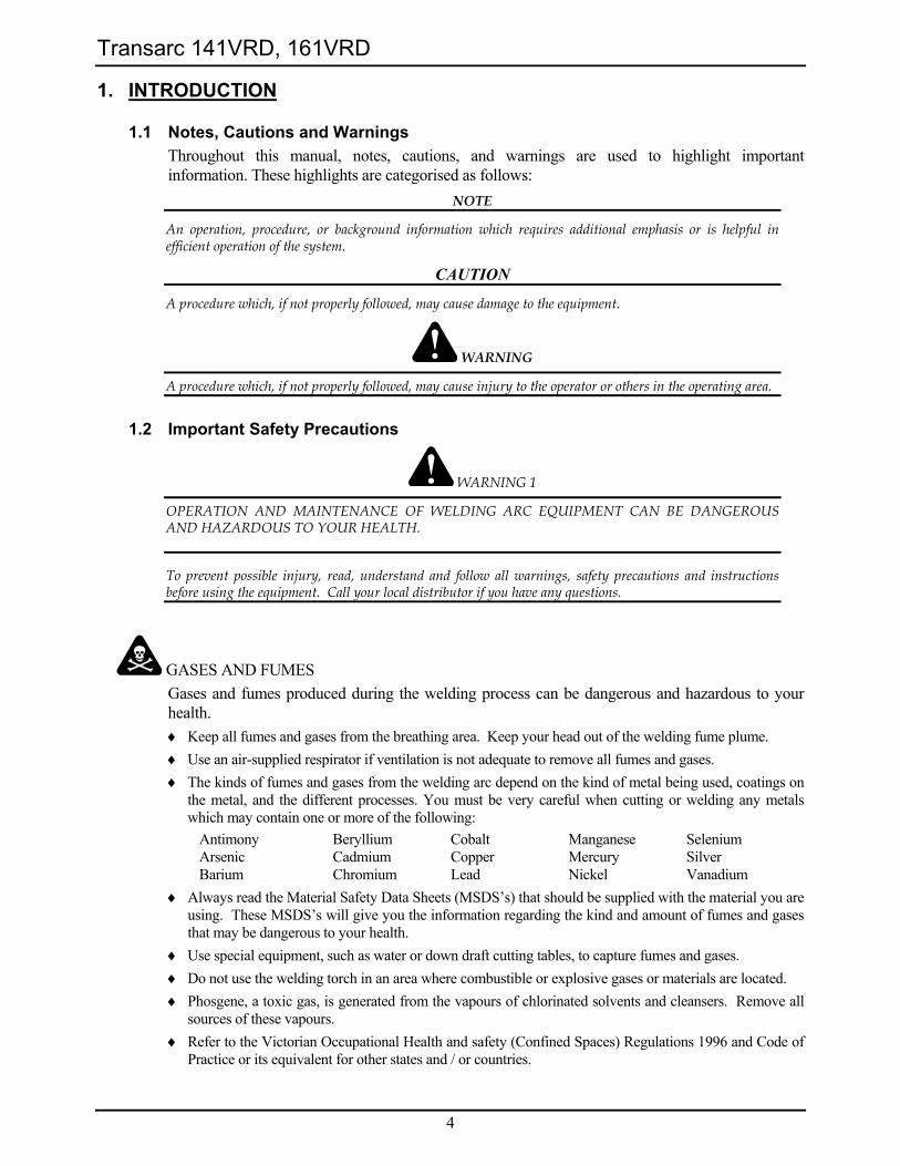
1.1 Notes, Cautions and Warnings Throughout this manual, notes, cautions, and warnings are used to highlight important information. These highlights are categorised as follows:
NOTE
An operation, procedure, or background information which requires additional emphasis or is helpful in efficient operation of the system.
CAUTION
A procedure which, if not properly followed, may cause damage to the equipment.
WARNING
A procedure which, if not properly followed, may cause injury to the operator or others in the operating area.
1.2 Important Safety Precautions
WARNING 1
OPERATION AND MAINTENANCE OF WELDING ARC EQUIPMENT CAN BE DANGEROUS AND HAZARDOUS TO YOUR HEALTH.
To prevent possible injury, read, understand and follow all warnings, safety precautions and instructions before using the equipment. Call your local distributor if you have any questions.
GASES AND FUMES Gases and fumes produced during the welding process can be dangerous and hazardous to your health. ♦ Keep all fumes and gases from the breathing area. Keep your head out of the welding fume plume. ♦ Use an air-supplied respirator if ventilation is not adequate to remove all fumes and gases. ♦ The kinds of fumes and gases from the welding arc depend on the kind of metal being used, coatings on
the metal, and the different processes. You must be very careful when cutting or welding any metals which may contain one or more of the following:
Antimony Beryllium Cobalt Manganese Selenium Arsenic Cadmium Copper Mercury Silver Barium Chromium Lead Nickel Vanadium
♦ Always read the Material Safety Data Sheets (MSDS’s) that should be supplied with the material you are using. These MSDS’s will give you the information regarding the kind and amount of fumes and gases that may be dangerous to your health.
♦ Use special equipment, such as water or down draft cutting tables, to capture fumes and gases. ♦ Do not use the welding torch in an area where combustible or explosive gases or materials are located. ♦ Phosgene, a toxic gas, is generated from the vapours of chlorinated solvents and cleansers. Remove all
sources of these vapours. ♦ Refer to the Victorian Occupational Health and safety (Confined Spaces) Regulations 1996 and Code of
Practice or its equivalent for other states and / or countries.
Transarc 141VRD, 161VRD
5
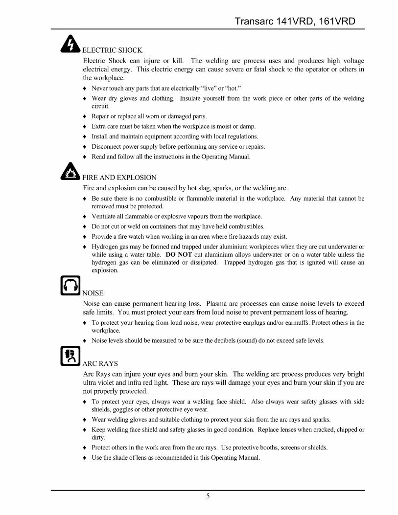
ELECTRIC SHOCK Electric Shock can injure or kill. The welding arc process uses and produces high voltage electrical energy. This electric energy can cause severe or fatal shock to the operator or others in the workplace. ♦ Never touch any parts that are electrically “live” or “hot.” ♦ Wear dry gloves and clothing. Insulate yourself from the work piece or other parts of the welding
circuit. ♦ Repair or replace all worn or damaged parts. ♦ Extra care must be taken when the workplace is moist or damp. ♦ Install and maintain equipment according with local regulations. ♦ Disconnect power supply before performing any service or repairs. ♦ Read and follow all the instructions in the Operating Manual.
FIRE AND EXPLOSION Fire and explosion can be caused by hot slag, sparks, or the welding arc. ♦ Be sure there is no combustible or flammable material in the workplace. Any material that cannot be
removed must be protected. ♦ Ventilate all flammable or explosive vapours from the workplace. ♦ Do not cut or weld on containers that may have held combustibles. ♦ Provide a fire watch when working in an area where fire hazards may exist. ♦ Hydrogen gas may be formed and trapped under aluminium workpieces when they are cut underwater or
while using a water table. DO NOT cut aluminium alloys underwater or on a water table unless the hydrogen gas can be eliminated or dissipated. Trapped hydrogen gas that is ignited will cause an explosion.
NOISE Noise can cause permanent hearing loss. Plasma arc processes can cause noise levels to exceed safe limits. You must protect your ears from loud noise to prevent permanent loss of hearing. ♦ To protect your hearing from loud noise, wear protective earplugs and/or earmuffs. Protect others in the
workplace. ♦ Noise levels should be measured to be sure the decibels (sound) do not exceed safe levels.
ARC RAYS Arc Rays can injure your eyes and burn your skin. The welding arc process produces very bright ultra violet and infra red light. These arc rays will damage your eyes and burn your skin if you are not properly protected. ♦ To protect your eyes, always wear a welding face shield. Also always wear safety glasses with side
shields, goggles or other protective eye wear. ♦ Wear welding gloves and suitable clothing to protect your skin from the arc rays and sparks. ♦ Keep welding face shield and safety glasses in good condition. Replace lenses when cracked, chipped or
dirty. ♦ Protect others in the work area from the arc rays. Use protective booths, screens or shields. ♦ Use the shade of lens as recommended in this Operating Manual.
Transarc 141VRD, 161VRD
6
2. ELECTROMAGNETIC COMPATIBILITY
WARNING 2
Extra precautions for Electromagnetic Compatibility may be required when this Welding Power Source is used in a domestic situation.
2.1 Installation and use - Users Responsibility The user is responsible for installing and using the welding equipment according to the manufacturer’s instructions. If electromagnetic disturbances are detected then it shall be the responsibility of the user of the welding equipment to resolve the situation with the technical assistance of the manufacturer. In some cases this remedial action may be as simple as earthing the welding circuit, see NOTE 1. In other cases it could involve constructing an electromagnetic screen enclosing the Welding Power Source and the work, complete with associated input filters. In all cases, electromagnetic disturbances shall be reduced to the point where they are no longer troublesome.
NOTE 1
The welding circuit may or may not be earthed for safety reasons. Changing the earthing arrangements should only be authorised by a person who is competent to assess whether the changes will increase the risk of injury, e.g. by allowing parallel welding current return paths which may damage the earth circuits of other equipment. Further guidance is given in IEC 974-13 Arc Welding Equipment - Installation and use (under preparation).
2.2 Assessment of Area Before installing welding equipment, the user shall make an assessment of potential electromagnetic problems in the surrounding area. The following shall be taken into account
i) Other supply cables, control cables, signalling and telephone cables; above, below and adjacent to the welding equipment.
ii) Radio and television transmitters and receivers. iii) Computer and other control equipment. iv) Safety critical equipment, e.g. guarding of industrial equipment. v) The health of people around, e.g. the use of pacemakers and hearing aids. vi) Equipment used for calibration and measurement. vii) The time of day that welding or other activities are to be carried out. viii) The immunity of other equipment in the environment: the user shall ensure that
other equipment being used in the environment is compatible: this may require additional protection measures.
The size of the surrounding area to be considered will depend on the structure of the building and other activities that are taking place. The surrounding area may extend beyond the boundaries of the premises.
2.3 Methods of Reducing Electromagnetic Emissions
a) Mains Supply Welding equipment should be connected to the mains supply according to the manufacturer’s recommendations. If interference occurs, it may be necessary to take additional precautions such as filtering of the mains supply. Consideration should be given to shielding the supply cable of permanently installed welding equipment in metallic conduit or equivalent.
Transarc 141VRD, 161VRD
7
Shielding should be electrically continuous throughout its length. The shielding should be connected to the Welding Power Source so that good electrical contact is maintained between the conduit and the Welding Power Source enclosure.
b) Maintenance of Welding Equipment The welding equipment should be routinely maintained according to the manufacturer’s recommendations. All access and service doors and covers should be closed and properly fastened when the welding equipment is in operation. The welding equipment should not be modified in any way except for those changes and adjustments covered in the manufacturer’s instructions. In particular, the spark gaps of arc striking and stabilising devices should be adjusted and maintained according to the manufacturer’s recommendations.
c) Welding Cables The welding cables should be kept as short as possible and should be positioned close together, running at or close to the floor level.
d) Equipotential Bonding Bonding of all metallic components in the welding installation and adjacent to it should be considered. However, metallic components bonded to the work piece will increase the risk that the operator could receive a shock by touching the metallic components and the electrode at the same time. The operator should be insulated from all such bonded metallic components.
e) Earthing of the Workpiece Where the workpiece is not bonded to earth for electrical safety, nor connected to earth because of it’s size and position, e.g. ship’s hull or building steelwork, a connection bonding the workpiece to earth may reduce emissions in some, but not all instances. Care should be taken to prevent the earthing of the workpiece increasing the risk of injury to users, or damage to other electrical equipment. Where necessary, the connection of the workpiece to earth should be made by direct connection to the workpiece, but in some countries where direct connection is not permitted, the bonding should be achieved by suitable capacitance, selected according to national regulations.
f) Screening and Shielding Selective screening and shielding of other cables and equipment in the surrounding area may alleviate problems of interference. Screening the entire welding installation may be considered for special applications.
Transarc 141VRD, 161VRD
8
3. GENERAL INFORMATION
3.1 Transarc 141VRD The Transarc 141VRD is a 240 volt, single phase, constant current, 140 amps at 60% duty cycle, DC stick -lift TIG power source. Combine this with features like built in Voltage Reduction Device (VRD) in stick mode, robust construction, total digital control, lift TIG arc start, Pulse TIG, built-in hot start, built-in arc control and you’ve got the ultimate unit designed for professional MMAW (Stick welding) and GTAW (Lift TIG/Pulse Lift TIG) for DC weldable materials. All these features are laid out on an easy to use digital display front panel with a single index control knob and push button mode selection. The VRD improves operator safety. This feature reduces the Open Circuit Voltage to below 20 volts when the welding power source is on while not in use.
3.2 Transarc 161VRD The Transarc 161VRD is a 240 volt, single phase, constant current, 160 amps at 60% duty cycle, DC stick -lift TIG power source. Combine this with features like built in Voltage Reduction Device (VRD) in stick mode, robust construction, total digital control, lift TIG arc start, Pulse TIG, built-in hot start, built-in arc control and you’ve got the ultimate unit designed for professional MMAW (Stick welding) and GTAW (Lift TIG/Pulse Lift TIG) for DC weldable materials. All these features are laid out on an easy to use digital display front panel with a single index control knob and push button mode selection. The VRD improves operator safety. This feature reduces the Open Circuit Voltage to below 20 volts when the welding power source is on while not in use.
3.3 User Responsibility This equipment will perform as per the information contained herein when installed, operated, maintained and repaired in accordance with the instructions provided. This equipment must be checked periodically. Defective equipment (including welding leads) should not be used. Parts that are broken, missing, plainly worn, distorted or contaminated, should be replaced immediately. Should such repairs or replacements become necessary, it is recommended that appropriately qualified persons approved by CIGWELD carry out such repairs. Advice in this regard can be obtained by contacting accredited CIGWELD Distributor. This equipment or any of its parts should not be altered from standard specification without prior written approval of CIGWELD. The user of this equipment shall have the sole responsibility for any malfunction which results from improper use or unauthorised modification from standard specification, faulty maintenance, damage or improper repair by anyone other than appropriately qualified persons approved by CIGWELD.
3.4 Duty Cycle Duty Cycle is the amount of arc-on time (actual welding or cutting time) during any 10 minute period that a machine can operate at it’s rated output without damaging internal components. For example, the Transarc 161VRD is designed for 60% duty cycle at 160 amps. This means that it has been designed and built to provide the rated amperage, 160 amps, for 6 minutes out of every 10 minute period (60% of 10 minutes is 6 minutes). During the other 4 minutes of the 10 minute period the Transarc 161VRD must idle and be allowed to cool. The thermal cutout will operate if the duty cycle is exceeded. As a general rule, a machine rated at 30% to 60% duty cycle would be more than ample duty cycle for the majority of general-purpose non-automatic welding or cutting applications.
Transarc 141VRD, 161VRD
9
Note that all duty cycles are calculated for a maximum ambient temperature of 40°C as per AS1966. Duty cycles must be reduced, ie reduce the arc-on time, when the ambient temperature exceeds 40°C.
3.5 Terms Of Warranty - June 2002
1. The Trade Practices Act 1974 (Commonwealth) and similar State Territory legislation relating to the supply of goods and services, protects consumers' interests by ensuring that consumers are entitled in certain situations to the benefit of various conditions, warranties, guarantees, rights and remedies (including warranties as to merchantability and fitness for purpose) associated with the supply of goods and services. A consumer should seek legal advice as to the nature and extent of these protected interests. In some circumstances, the supplier of goods and services may legally stipulate that the said conditions, warranties, guarantees, rights and remedies are limited or entirely excluded. The warranties set out in Clause 2 shall be additional to any non-excludable warranties to which the Customer may be entitled pursuant to any statute.
2. Subject to Clause 3. CIGWELD gives the following warranties to the Customer:
Insofar as they are manufactured or imported by CIGWELD, goods will upon delivery be of merchantable quality and reasonably fit for the purpose for which they are supplied by CIGWELD.
CIGWELD will repair or, at its option, replace those of the goods which, upon examination, are found by CIGWELD to be defective in workmanship and/or materials.
CIGWELD reserves the right to request documented evidence of date of purchase.
3. The Warranty in Clause 2;
Is conditional upon:
The Customer notifying CIGWELD or our Accredited Distributor in writing of its claim within seven (7) days of becoming aware of the basis thereof, and at its own expense returning the goods which are the subject of the claim to CIGWELD or nominated Accredited Distributor/Accredited Service Agent.
The goods being used in accordance with the Manufacturer's Operating Manuals, and under competent supervision.
Does not apply to:
Obsolete goods sold at auction, second-hand goods and prototype goods.
Breakdown or malfunction caused by accident, misuse or normal wear and tear.
Repairs or replacement made other than by CIGWELD or Accredited Service Agents, unless by prior arrangement with CIGWELD.
Replacement parts or accessories which may affect product safety or performance and which are not manufactured, distributed or approved by CIGWELD.
4. CIGWELD declares that, to the extent permitted by law, it hereby limits its liability in respect of the supply of goods which are not of a kind ordinarily acquired for personal, domestic or household use or consumption to any one or more of the following (the choice of which shall be at the option of CIGWELD).
The replacement of the goods or the supply of equivalent goods.
The repair of goods.
The payment of cost of replacing the goods or acquiring equivalent goods.
The payment of the cost of having goods repaired.
5. Except as provided in Clauses 2 to 4 above, to the extent permitted by statute, CIGWELD hereby excludes all liability for any loss, damage, death or injury of any kind whatsoever occasioned to the Customer in respect of the supply of goods including direct, indirect, consequential or incidental loss, damage or injury of any kind.
Transarc 141VRD, 161VRD
10
3.6 Warranty Schedule - June 2003 These warranty periods relate to the warranty conditions in clause 2. All warranty periods are from date of sale from the Accredited Distributor of the equipment. Notwithstanding the foregoing, in no event shall the warranty period extend more than the time stated plus one year from the date CIGWELD delivered the product to the Accredited Distributor. Unless otherwise stated the warranty period includes parts and labour. CIGWELD reserves the right to request documented evidence of date of purchase. Transarc 141VRD, 161VRD WARRANTY PERIOD
Main Power Magnetics ..................................................................................................18 months Original Main Power Rectifiers, Control P.C. Boards...................................................18 months All other circuits and components including, but not limited to, relays, switches, contactors, solenoids, fans, power switch semi-conductors.............................. 1 year
Please note that the information detailed in this statement supersedes any prior published data produced by CIGWELD.
WARNING 3
For the purpose of safety and performance and to protect your CIGWELD Equipment Warranty always use genuine CIGWELD replacement parts and accessories.
4. SAFE PRACTICES FOR THE USE OF WELDING EQUIPMENT In many situations the “striking” voltage can be hazardous. Any person touching simultaneously the electrode lead/terminal and the work lead/terminal may receive a serious electrical shock. Additional precautions must be exercised where two Welding Power Sources are being used close to each other because, under certain conditions, the voltages between the welding terminals of the two Welding Power Sources could be two times the specified open circuit voltage. It is essential that the Welding Power Source be correctly installed, if necessary, by a qualified electrician and maintained in sound mechanical and electrical condition. It is also important that the Welding Power Source be switched off when not in use.
4.1 Precautions to be Taken by Operators ♦ Whenever practicable, all parts of the welding circuit should be isolated from earth and other conducting
material and under no circumstances should any earthing conductor of the electrical installation be used in place of the work lead.
♦ The Mains supply voltage should be switched off before connecting or disconnecting welding leads. Welding lead connections must have clean contact surfaces and must be securely tightened. Poor connections will result in overheating and loss of welding current. All parts of the welding circuit, including the return paths, are to be considered electrically alive, so the operator must ensure that no part of the body is placed in such a position that it will provide a path for an electric current.
♦ Welding operators should avoid direct contact with the work to be welded or against any metal in contact with the work. When this cannot be avoided the operator must not touch any exposed portion of the electrode holder with any part of the body. Should this occur, the operator will risk completing the electrical circuit through the body.
♦ When welding in confined spaces, where reasonable movement is restricted, particular care must be taken to ensure that the area is well ventilated and the operator is under constant observation by a person who can immediately switch off the power and give assistance in an emergency.
♦ The flux covering of an electrode cannot be assumed to provide effective insulation, consequently an insulating glove must be worn when placing an electrode into its holder, or should it be necessary to handle an electrode once it is in contact with its holder.
♦ During pauses between welding runs, electrode holders should be so placed that they cannot make electrical contact with persons or conductive objects.
♦ The welding leads, both the electrode lead and the work lead, must be protected from damage. Damaged leads must not be used.
♦ Keep combustible materials away from the welding area. Have a suitable fire extinguisher handy.
Transarc 141VRD, 161VRD
11
♦ Do not stand on damp ground when welding.
4.2 Personal Protection The radiation from an electric arc during the welding process can seriously harm eyes and skin. It is essential that the following precautions be taken: ♦ Gloves should be flameproof gauntlet type to protect hands and wrists from heat burns and harmful
radiations. They should be kept dry and in good repair. ♦ Protective clothing must protect the operator from burns, spatter and harmful radiation. Woollen
clothing is preferable to cotton because of its greater flame resistance. Clothing should be free from oil or grease. Wear leggings and spats to protect the lower portion of the legs and to prevent slag and molten metal from falling into boots or shoes.
♦ Face Shield It is recommended to use a welding face shield, conforming to the relevant standards, when electric arc
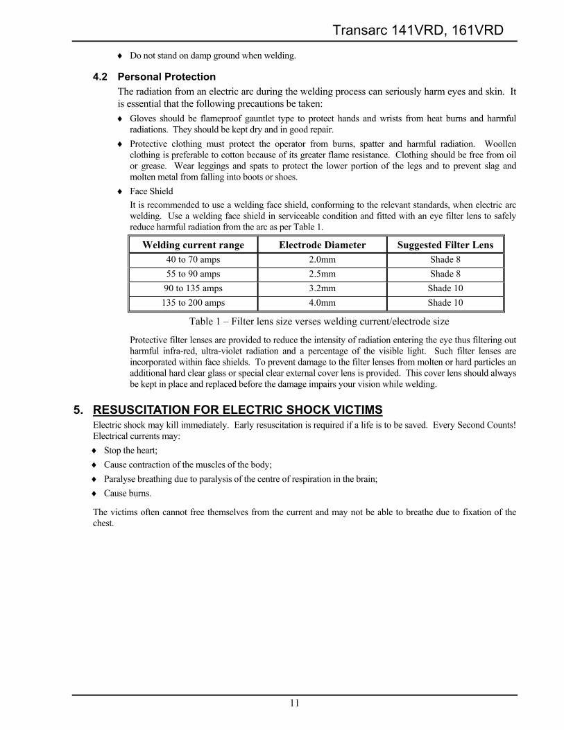
welding. Use a welding face shield in serviceable condition and fitted with an eye filter lens to safely reduce harmful radiation from the arc as per Table 1.
Welding current range Electrode Diameter Suggested Filter Lens 40 to 70 amps 2.0mm Shade 8 55 to 90 amps 2.5mm Shade 8 90 to 135 amps 3.2mm Shade 10 135 to 200 amps 4.0mm Shade 10
Table 1 – Filter lens size verses welding current/electrode size
Protective filter lenses are provided to reduce the intensity of radiation entering the eye thus filtering out harmful infra-red, ultra-violet radiation and a percentage of the visible light. Such filter lenses are incorporated within face shields. To prevent damage to the filter lenses from molten or hard particles an additional hard clear glass or special clear external cover lens is provided. This cover lens should always be kept in place and replaced before the damage impairs your vision while welding.
5. RESUSCITATION FOR ELECTRIC SHOCK VICTIMS Electric shock may kill immediately. Early resuscitation is required if a life is to be saved. Every Second Counts! Electrical currents may: ♦ Stop the heart; ♦ Cause contraction of the muscles of the body; ♦ Paralyse breathing due to paralysis of the centre of respiration in the brain; ♦ Cause burns.
The victims often cannot free themselves from the current and may not be able to breathe due to fixation of the chest.
Transarc 141VRD, 161VRD
12
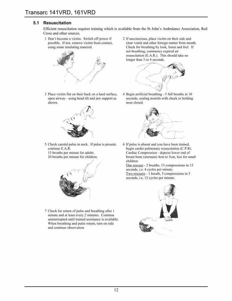
5.1 Resuscitation Efficient resuscitation requires training which is available from the St John’s Ambulance Association, Red Cross and other sources. 1 Don’t become a victim. Switch off power if
possible. If not, remove victim from contact, using some insulating material.
2 If unconscious, place victim on their side and clear vomit and other foreign matter from mouth. Check for breathing by look, listen and feel. If not breathing, commence expired air resuscitation (E.A.R.). This should take no longer than 3 or 4 seconds.
3 Place victim flat on their back on a hard surface,
open airway - using head tilt and jaw support as shown.
4 Begin artificial breathing - 5 full breaths in 10 seconds, sealing nostrils with cheek or holding nose closed.
5 Check carotid pulse in neck. If pulse is present,
continue E.A.R. 15 breaths per minute for adults. 20 breaths per minute for children.
7 Check for return of pulse and breathing after 1
minute and at least every 2 minutes. Continue uninterrupted until trained assistance is available. When breathing and pulse return, turn on side and continue observation.
6 If pulse is absent and you have been trained, begin cardio pulmonary resuscitation (C.P.R). Cardiac Compression - depress lower end of breast bone (sternum) 4cm to 5cm, less for small children. One rescuer - 2 breaths, 15 compressions in 15 seconds, i.e. 4 cycles per minute. Two rescuers - 1 breath, 5 compressions in 5 seconds, i.e. 12 cycles per minute.
Transarc 141VRD, 161VRD
13
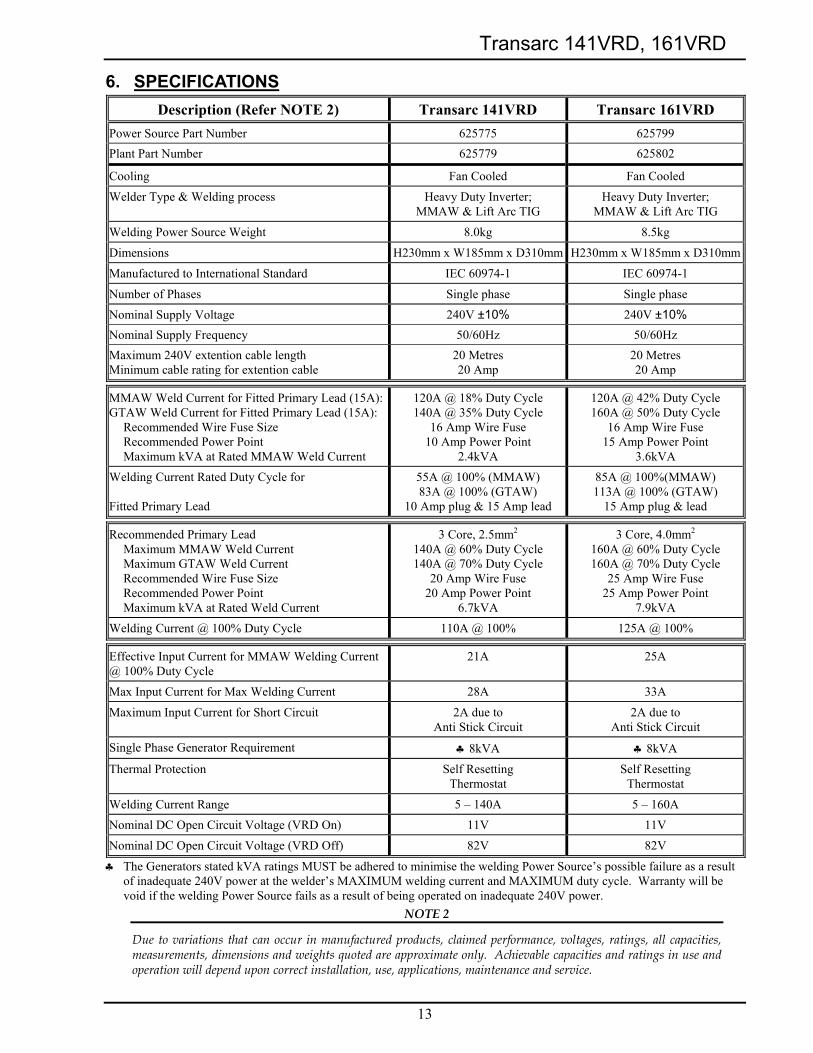
6. SPECIFICATIONS Description (Refer NOTE 2) Transarc 141VRD Transarc 161VRD
Power Source Part Number 625775 625799 Plant Part Number 625779 625802
Cooling Fan Cooled Fan Cooled
Welder Type & Welding process Heavy Duty Inverter; MMAW & Lift Arc TIG
Heavy Duty Inverter; MMAW & Lift Arc TIG
Welding Power Source Weight 8.0kg 8.5kg
Dimensions H230mm x W185mm x D310mm H230mm x W185mm x D310mm
Manufactured to International Standard IEC 60974-1 IEC 60974-1
Number of Phases Single phase Single phase
Nominal Supply Voltage 240V ±10% 240V ±10% Nominal Supply Frequency 50/60Hz 50/60Hz Maximum 240V extention cable length Minimum cable rating for extention cable
20 Metres 20 Amp
20 Metres 20 Amp
MMAW Weld Current for Fitted Primary Lead (15A): GTAW Weld Current for Fitted Primary Lead (15A): Recommended Wire Fuse Size Recommended Power Point Maximum kVA at Rated MMAW Weld Current
120A @ 18% Duty Cycle 140A @ 35% Duty Cycle
16 Amp Wire Fuse 10 Amp Power Point
2.4kVA
120A @ 42% Duty Cycle 160A @ 50% Duty Cycle
16 Amp Wire Fuse 15 Amp Power Point
3.6kVA Welding Current Rated Duty Cycle for Fitted Primary Lead
55A @ 100% (MMAW) 83A @ 100% (GTAW)
10 Amp plug & 15 Amp lead
85A @ 100%(MMAW) 113A @ 100% (GTAW)
15 Amp plug & lead
Recommended Primary Lead Maximum MMAW Weld Current Maximum GTAW Weld Current Recommended Wire Fuse Size Recommended Power Point Maximum kVA at Rated Weld Current
3 Core, 2.5mm2 140A @ 60% Duty Cycle 140A @ 70% Duty Cycle
20 Amp Wire Fuse 20 Amp Power Point
6.7kVA
3 Core, 4.0mm2 160A @ 60% Duty Cycle 160A @ 70% Duty Cycle
25 Amp Wire Fuse 25 Amp Power Point
7.9kVA Welding Current @ 100% Duty Cycle 110A @ 100% 125A @ 100%
Effective Input Current for MMAW Welding Current @ 100% Duty Cycle
21A 25A
Max Input Current for Max Welding Current 28A 33A
Maximum Input Current for Short Circuit 2A due to Anti Stick Circuit
2A due to Anti Stick Circuit
Single Phase Generator Requirement ♣ 8kVA ♣ 8kVA
Thermal Protection Self Resetting Thermostat
Self Resetting Thermostat
Welding Current Range 5 – 140A 5 – 160A Nominal DC Open Circuit Voltage (VRD On) 11V 11V
Nominal DC Open Circuit Voltage (VRD Off) 82V 82V
♣ The Generators stated kVA ratings MUST be adhered to minimise the welding Power Source’s possible failure as a result of inadequate 240V power at the welder’s MAXIMUM welding current and MAXIMUM duty cycle. Warranty will be void if the welding Power Source fails as a result of being operated on inadequate 240V power.
NOTE 2
Due to variations that can occur in manufactured products, claimed performance, voltages, ratings, all capacities, measurements, dimensions and weights quoted are approximate only. Achievable capacities and ratings in use and operation will depend upon correct installation, use, applications, maintenance and service.
Transarc 141VRD, 161VRD
14
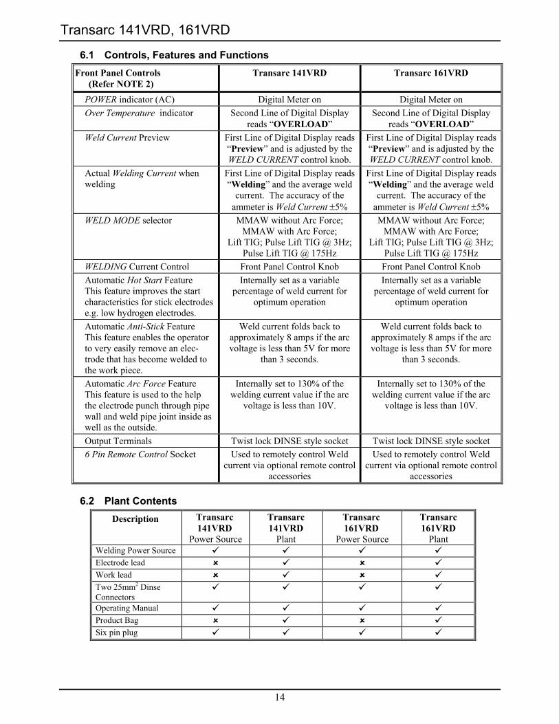
6.1 Controls, Features and Functions Front Panel Controls
(Refer NOTE 2) Transarc 141VRD Transarc 161VRD
POWER indicator (AC) Digital Meter on Digital Meter on Over Temperature indicator Second Line of Digital Display
reads “OVERLOAD” Second Line of Digital Display
reads “OVERLOAD” Weld Current Preview First Line of Digital Display reads
“Preview” and is adjusted by the WELD CURRENT control knob.
First Line of Digital Display reads “Preview” and is adjusted by the WELD CURRENT control knob.
Actual Welding Current when welding
First Line of Digital Display reads “Welding” and the average weld
current. The accuracy of the ammeter is Weld Current ±5%
First Line of Digital Display reads “Welding” and the average weld
current. The accuracy of the ammeter is Weld Current ±5%
WELD MODE selector MMAW without Arc Force; MMAW with Arc Force;
Lift TIG; Pulse Lift TIG @ 3Hz;Pulse Lift TIG @ 175Hz
MMAW without Arc Force; MMAW with Arc Force;
Lift TIG; Pulse Lift TIG @ 3Hz;Pulse Lift TIG @ 175Hz
WELDING Current Control Front Panel Control Knob Front Panel Control Knob Automatic Hot Start Feature
This feature improves the start characteristics for stick electrodes e.g. low hydrogen electrodes.
Internally set as a variable percentage of weld current for
optimum operation
Internally set as a variable percentage of weld current for
optimum operation
Automatic Anti-Stick Feature This feature enables the operator to very easily remove an elec-trode that has become welded to the work piece.
Weld current folds back to approximately 8 amps if the arc voltage is less than 5V for more
than 3 seconds.
Weld current folds back to approximately 8 amps if the arc voltage is less than 5V for more
than 3 seconds.
Automatic Arc Force Feature This feature is used to the help the electrode punch through pipe wall and weld pipe joint inside as well as the outside.
Internally set to 130% of the welding current value if the arc
voltage is less than 10V.
Internally set to 130% of the welding current value if the arc
voltage is less than 10V.
Output Terminals Twist lock DINSE style socket Twist lock DINSE style socket 6 Pin Remote Control Socket Used to remotely control Weld
current via optional remote control accessories
Used to remotely control Weld current via optional remote control
accessories
6.2 Plant Contents Description Transarc
141VRD Power Source
Transarc 141VRD
Plant
Transarc 161VRD
Power Source
Transarc 161VRD
Plant Welding Power Source Electrode lead Work lead Two 25mm2 Dinse Connectors
Operating Manual Product Bag Six pin plug
Transarc 141VRD, 161VRD
15
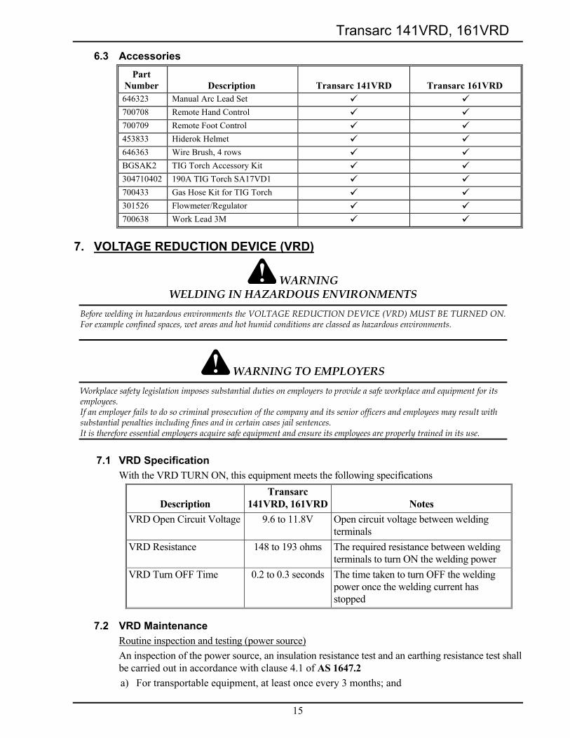
6.3 Accessories Part
Number
Description
Transarc 141VRD
Transarc 161VRD 646323 Manual Arc Lead Set 700708 Remote Hand Control 700709 Remote Foot Control 453833 Hiderok Helmet 646363 Wire Brush, 4 rows BGSAK2 TIG Torch Accessory Kit 304710402 190A TIG Torch SA17VD1 700433 Gas Hose Kit for TIG Torch 301526 Flowmeter/Regulator 700638 Work Lead 3M
7. VOLTAGE REDUCTION DEVICE (VRD)
WARNING WELDING IN HAZARDOUS ENVIRONMENTS
Before welding in hazardous environments the VOLTAGE REDUCTION DEVICE (VRD) MUST BE TURNED ON. For example confined spaces, wet areas and hot humid conditions are classed as hazardous environments.
WARNING TO EMPLOYERS Workplace safety legislation imposes substantial duties on employers to provide a safe workplace and equipment for its employees. If an employer fails to do so criminal prosecution of the company and its senior officers and employees may result with substantial penalties including fines and in certain cases jail sentences. It is therefore essential employers acquire safe equipment and ensure its employees are properly trained in its use.
7.1 VRD Specification With the VRD TURN ON, this equipment meets the following specifications
Description
Transarc 141VRD, 161VRD
Notes
VRD Open Circuit Voltage 9.6 to 11.8V Open circuit voltage between welding terminals
VRD Resistance 148 to 193 ohms The required resistance between welding terminals to turn ON the welding power
VRD Turn OFF Time 0.2 to 0.3 seconds The time taken to turn OFF the welding power once the welding current has stopped
7.2 VRD Maintenance Routine inspection and testing (power source) An inspection of the power source, an insulation resistance test and an earthing resistance test shall be carried out in accordance with clause 4.1 of AS 1647.2 a) For transportable equipment, at least once every 3 months; and
Transarc 141VRD, 161VRD
16
b) For fixed equipment, at least once every 12 months.
The owners of the equipment shall keep a suitable record of the periodic tests. Note 3
A transportable power source is any equipment that is not permanently connected and fixed in the position in which it is operated.
In addition to the above tests and specifically in relation to the VRD fitted to this machine, the following periodic tests should also be conducted by an accredited CIGWELD service agent.
Description AS3195 & IEC 60974-1 Requirements VRD Open Circuit Voltage Less than 20V; at Vin=240V VRD Turn ON Resistance Less than 200 ohms VRD Turn OFF Time Less than 0.3 seconds
If this equipment is used in a hazardous location or environments with a high risk of electrocution then the above tests should be carried out prior to entering this location.
8. INSTALLATION RECOMMENDATIONS
8.1 Environment The Transarc 141VRD, 161VRD are designed for use in hazardous environments when the VRD is TURNED ON.
a) Examples of environments with increased hazard of electric shock are - i) In locations in which freedom of movement is restricted, so that the operator is
forced to perform the work in a cramped (kneeling, sitting or lying) position with physical contact with conductive parts;
ii) In locations which are fully or partially limited by conductive elements, and in which there is a high risk of unavoidable or accidental contact by the operator, or
iii) In wet or damp hot locations where humidity or perspiration considerable reduces the skin resistance of the human body and the insulation properties of accessories.
b) Environments with increased hazard of electric shock do not include places where electrically conductive parts in the near vicinity of the operator, which can cause increased hazard, have been insulated.
8.2 Location Be sure to locate the welder according to the following guidelines: a) In areas, free from moisture and dust. b) Ambient temperature between 0°C to 40°C. c) In areas, free from oil, steam and corrosive gases. d) In areas, not subjected to abnormal vibration or shock. e) In areas, not exposed to direct sunlight or rain. f) Place at a distance of 300mm or more from walls or similar that could restrict natural
airflow for cooling.
8.3 Ventilation Since the inhalation of welding fumes can be harmful, ensure that the welding area is effectively ventilated.
Transarc 141VRD, 161VRD
17
8.4 Mains Supply Voltage Requirements The Mains supply voltage should be within ± 10% of the rated Mains supply voltage. Too low a voltage may cause the fuse or circuit breaker to rupture due to the increased primary current. Too high a supply voltage will cause the Power Source components to fail.
8.5 Minimum 240V Mains Current Circuit Requirements CAUTION 1
CIGWELD recommends that the maximum 240V extention cable length used with this equipment is 20 metres. Refer to the Specification on page 13.
The Welding Power Source must be: ♦ Correctly installed, if necessary, by a qualified electrician. ♦ Correctly earthed (electrically) in accordance with local regulations. ♦ Connected to the correct size 240V Mains Current Circuit as per the SPECIFICATIONS on
page 13.
WARNING 4
CIGWELD advises that this equipment be electrically connected by a qualified electrical trades-person.
The following 240V Mains Current Circuit recommendations are required to obtain the maximum welding current and duty cycle from your equipment:
Model Mains Supply Lead Size
Recommended 240V Mains
Outlet
Recommended 240V Mains Fuse
MMAW Current & Duty Cycle
Transarc 141VRD 2.5 mm2 20 Amp Outlet 20 Amp wire fuse 140A @ 60%
Transarc 161VRD 4.0 mm2 25 Amp Outlet 25 Amp wire fuse 160A @ 60%
Table 2 – 240V Mains Outlet & Fuse sizes to achieve maximum MMAW current
9. POWER SOURCE CONTROLS
9.1 Transarc 141VRD and Transarc 161VRD Controls
a) ON/OFF Switch and Power ON Indicator This switch connects the 240V power to the inverter when in the ON position. This enables the user to commence welding. It illuminates when the welder is connected to 240V and the ON/OFF Switch is ON.
WARNING 5
Switch the ON/OFF switch to the OFF position before disconnecting the primary supply lead from the power point. When the welder is connected to the Mains supply voltage, the internal electrical components maybe at 240V potential.
Weld Process
W
EL
D CURRENT
ON OFFVRD
Refer to Manualfor correct use
SWITCH OFF Before Disconnecting Primary Lead
NegativeTerminal
PositiveTerminal
Two LineDigital
Display
WeldingCurrentControl
ON/OFF Switchand Power OnIndicator
WeldModeSwitch
VRD ON/OFFIndicationLights
6 Pin RemoteControl Socket
Transarc 141VRD, 161VRD
18
b) Two Line Digital Display Preview Weld Current Preview Weld Current is displayed on the first top line of the display when the operator is not welding. The welding current is increased by turning the WELD CURRENT Control knob clockwise or decreased by turning it anti-clockwise. Weld Current when Welding Weld Current is displayed on the first top line of the display when the operator is welding and for 5 seconds after the arc has extinguished. Thermal Overload Indication The word “OVERLOAD” is displayed on the second line of the display and weld current ceases if the internal parts exceed their safe operating temperature. Over Primary Voltage The words “INPUT ERROR (V)” are displayed on the second line of the display and weld current ceases if the primary voltage exceeds 264Vac when the electrode comes into contact with the work piece. Weld Modes The following weld modes can be selected by pressing Weld Process button:
Weld Mode Second Line Digital Display
Comments
STICK “Stick” MMAW (Stick) with built-in Hot Start enabled. STICK + Arc Force
“Stick+Arc-Force”
MMAW (Stick) with built-in Hot Start & Arc Force enabled.
Lift TIG “Lift-TIG” Lift GTAW (TIG); Hot Start disabled. A torch switch must be used to establish a lift TIG arc.
Pulse Lift TIG at 3Hz
“Lift Pulse 3Hz”
Pulse Lift GTAW @ 3Hz; Hot Start disabled. A torch switch must be used to establish a lift TIG arc.
Pulse Lift TIG at 175Hz
“Lift Pulse 175Hz”
Pulse Lift GTAW @ 175Hz; Hot Start disabled. A torch switch must be used to establish a lift TIG arc.
c) WELD CURRENT Control The welding current is increased by turning the Current Control clockwise or decreased by turning the Current Control anti-clockwise.
d) Positive and Negative Terminals Welding current flows from the Power Source via heavy duty bayonet type terminals. It is essential, however, that the male plug is inserted and turned securely to achieve a sound electrical connection.
CAUTION 2
Loose welding terminal connections can cause overheating and result in the male plug being fused in the bayonet terminal.
e) Weld Mode Switch The Weld Mode switch selects the mode of operation as follows: i) STICK
The Power Source is set for manual arc welding, the Hot Start feature is enabled, the Anti-Stick feature is enabled and the Arc Force feature is disabled.
Transarc 141VRD, 161VRD
19
ii) STICK + Arc-Force The Power Source is set for manual arc welding, the Hot Start feature is enabled, the Anti-Stick feature is enabled and the Arc Force feature is enabled.
iii) Lift TIG The Power Source is set for TIG welding with lift arc start initiation; the Hot Start feature is disabled. Pressing the torch switch AND touching the tungsten on the work piece produces a very low starting current. Moving the tungsten steadily away from the work piece (with the torch switch still pressed) causes the output to ramp up to the WELD CURRENT control setting. Releasing the torch switch will extinguish the arc.
iv) Lift Pulse at 3Hz The Power Source is set for pulse TIG welding with lift arc start initiation at 3Hz, the Hot Start feature is disabled. Pressing the torch switch AND touching the tungsten on the work piece produces a very low starting current. Moving the tungsten steadily away from the work piece (with the torch switch still pressed) causes the output to ramp up to the WELD CURRENT control setting. Releasing the torch switch will extinguish the arc.
v) Lift Pulse at 175Hz The Power Source is set for pulse TIG welding with lift arc start initiation at 175Hz, the Hot Start feature is disabled. Pressing the torch switch AND touching the tungsten on the work piece produces a very low starting current. Moving the tungsten steadily away from the work piece (with the torch switch still pressed) causes the output to ramp up to the WELD CURRENT control setting. Releasing the torch switch will extinguish the arc.
f) VRD ON/OFF Indicator Lights These lights only operate in the MMAW (Stick) modes. In all the TIG modes both lights are turned off. The green VRD ON light illuminates (red light is OFF) when the OCV is less than 20 volts and no welding current is flowing. The red VRD OFF light illuminates (green light is OFF) when the OCV is greater than 20 volts or welding current is flowing.
g) 6 Pin Remote Control Socket The 6 pin Remote Control Socket is used to connect remote current control devices to the welding Power Source circuitry. To make connections, align keyway, insert plug, and rotate threaded collar fully clockwise. The socket information is included in the event the supplied cable is not suitable and it is necessary to wire a plug or cable to interface with the socket.
Transarc 141VRD, 161VRD
20
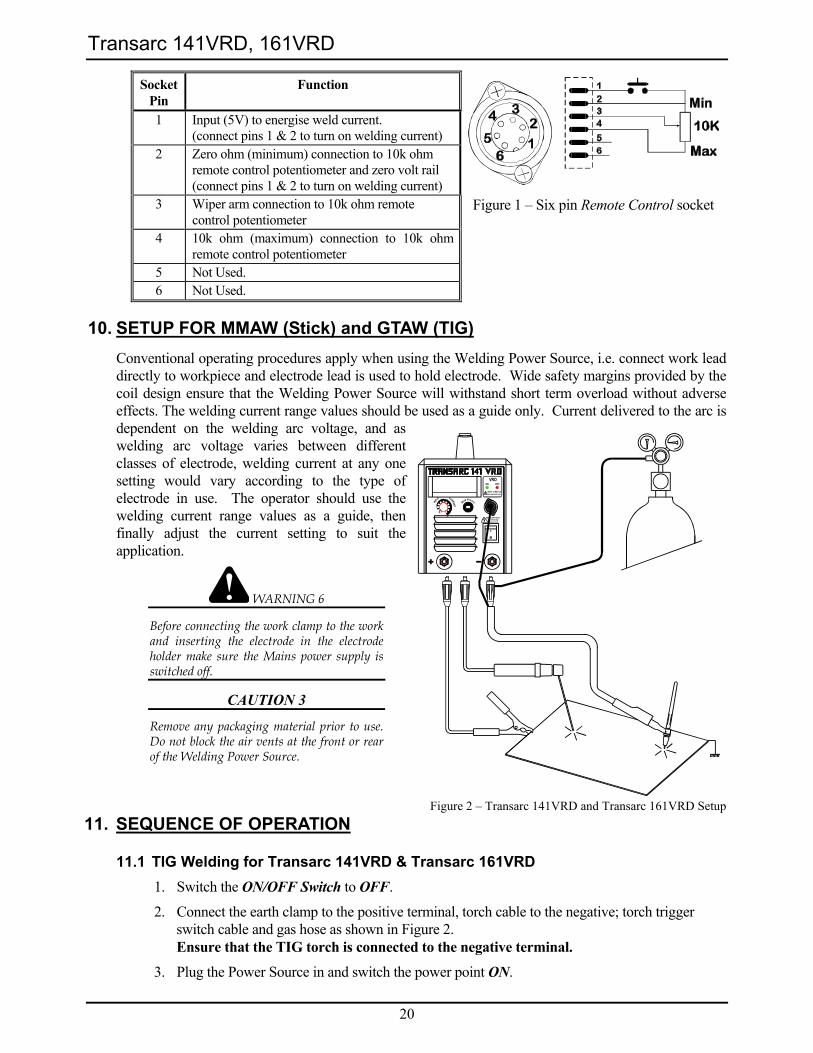
Socket Pin
Function
1 Input (5V) to energise weld current. (connect pins 1 & 2 to turn on welding current)
2 Zero ohm (minimum) connection to 10k ohm remote control potentiometer and zero volt rail (connect pins 1 & 2 to turn on welding current)
3 Wiper arm connection to 10k ohm remote control potentiometer
Figure 1 – Six pin Remote Control socket
4 10k ohm (maximum) connection to 10k ohm remote control potentiometer
5 Not Used. 6 Not Used.
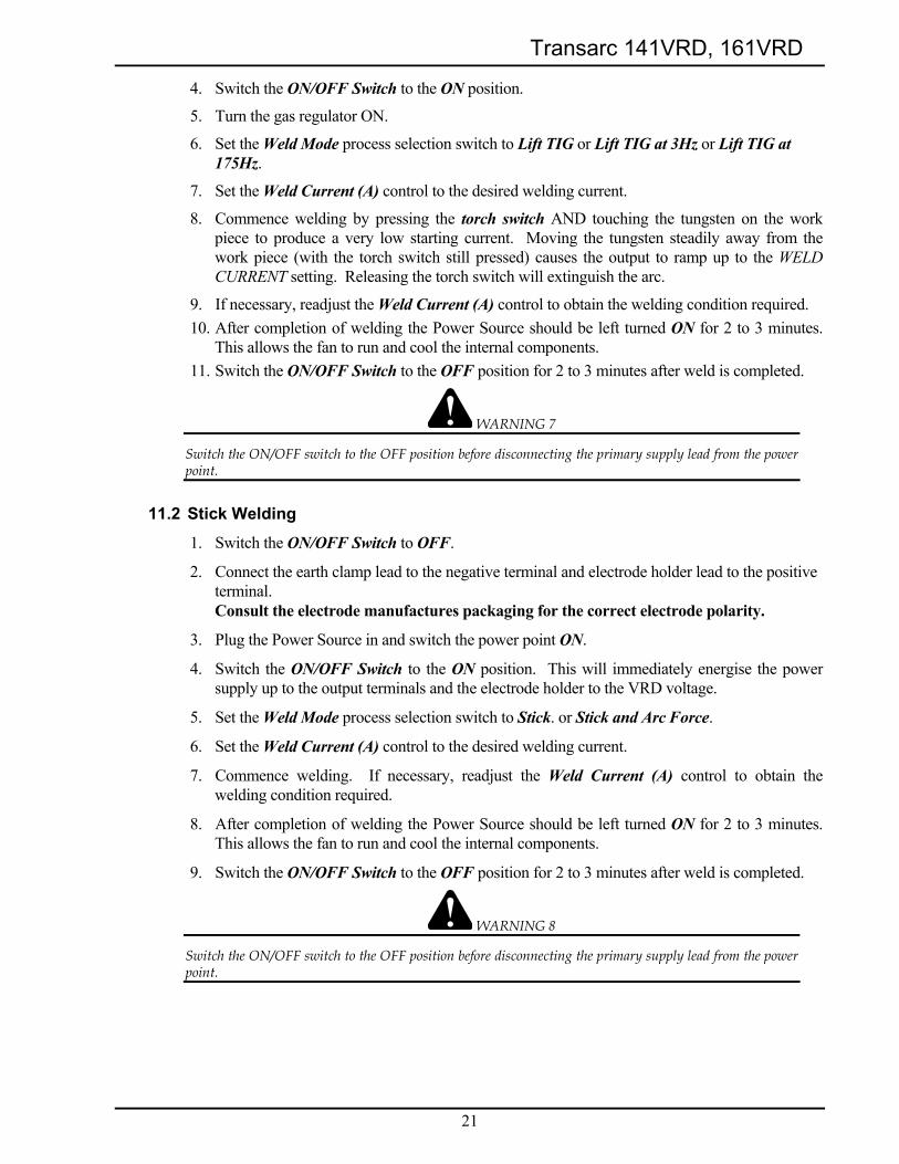
10. SETUP FOR MMAW (Stick) and GTAW (TIG) Conventional operating procedures apply when using the Welding Power Source, i.e. connect work lead directly to workpiece and electrode lead is used to hold electrode. Wide safety margins provided by the coil design ensure that the Welding Power Source will withstand short term overload without adverse effects. The welding current range values should be used as a guide only. Current delivered to the arc is dependent on the welding arc voltage, and as welding arc voltage varies between different classes of electrode, welding current at any one setting would vary according to the type of electrode in use. The operator should use the welding current range values as a guide, then finally adjust the current setting to suit the application.
WARNING 6
Before connecting the work clamp to the work and inserting the electrode in the electrode holder make sure the Mains power supply is switched off.
CAUTION 3
Remove any packaging material prior to use. Do not block the air vents at the front or rear of the Welding Power Source.
Figure 2 – Transarc 141VRD and Transarc 161VRD Setup 11. SEQUENCE OF OPERATION
11.1 TIG Welding for Transarc 141VRD & Transarc 161VRD 1. Switch the ON/OFF Switch to OFF.
2. Connect the earth clamp to the positive terminal, torch cable to the negative; torch trigger switch cable and gas hose as shown in Figure 2. Ensure that the TIG torch is connected to the negative terminal.
3. Plug the Power Source in and switch the power point ON.
Weld Process
W
EL
D CURRENT
ON OFFVRD
Refer to Manualfor correct use
SWITCH OFF Before Disconnecting Primary Lead
Transarc 141VRD, 161VRD
21
4. Switch the ON/OFF Switch to the ON position.
5. Turn the gas regulator ON.
6. Set the Weld Mode process selection switch to Lift TIG or Lift TIG at 3Hz or Lift TIG at 175Hz.
7. Set the Weld Current (A) control to the desired welding current.
8. Commence welding by pressing the torch switch AND touching the tungsten on the work piece to produce a very low starting current. Moving the tungsten steadily away from the work piece (with the torch switch still pressed) causes the output to ramp up to the WELD CURRENT setting. Releasing the torch switch will extinguish the arc.
9. If necessary, readjust the Weld Current (A) control to obtain the welding condition required. 10. After completion of welding the Power Source should be left turned ON for 2 to 3 minutes.
This allows the fan to run and cool the internal components. 11. Switch the ON/OFF Switch to the OFF position for 2 to 3 minutes after weld is completed.
WARNING 7
Switch the ON/OFF switch to the OFF position before disconnecting the primary supply lead from the power point.
11.2 Stick Welding
1. Switch the ON/OFF Switch to OFF.
2. Connect the earth clamp lead to the negative terminal and electrode holder lead to the positive terminal. Consult the electrode manufactures packaging for the correct electrode polarity.
3. Plug the Power Source in and switch the power point ON.
4. Switch the ON/OFF Switch to the ON position. This will immediately energise the power supply up to the output terminals and the electrode holder to the VRD voltage.
5. Set the Weld Mode process selection switch to Stick. or Stick and Arc Force.
6. Set the Weld Current (A) control to the desired welding current.
7. Commence welding. If necessary, readjust the Weld Current (A) control to obtain the welding condition required.
8. After completion of welding the Power Source should be left turned ON for 2 to 3 minutes. This allows the fan to run and cool the internal components.
9. Switch the ON/OFF Switch to the OFF position for 2 to 3 minutes after weld is completed.
WARNING 8
Switch the ON/OFF switch to the OFF position before disconnecting the primary supply lead from the power point.
Transarc 141VRD, 161VRD
22
12. BASIC TIG WELDING GUIDE
12.1 Electrode Polarity Connect the TIG torch to the ‘-’ terminal and the work lead to the ‘+’ terminal for direct current straight polarity. Direct current straight polarity is the most widely used polarity for DC TIG welding. It allows limited wear of the electrode since 70% of the heat is concentrated at the work piece.
12.2 Tungsten Electrode Current Ranges
Electrode Diameter (mm) DC Current (Amps)
1.0 30 – 60
1.6 60 – 115
2.4 100 – 165
3.2 135 – 200
4.0 190 – 280
4.8 250 – 340
Table 3 – Current ranges for varies tungsten electrode sizes
12.3 CIGWELD Tungsten Electrode Types
Electrode Type (Ground Finish)
Welding Application Features Colour Code
Thoriated 2%
DC welding of mild steel, stainless steel and copper.
Excellent arc starting, Long life, High current carrying capacity.
Red
Zirconated 1%
High quality AC welding of aluminium, magnesium and their alloys.
Self cleaning, Long life, Maintains balled end, High current carrying capacity.
White
Ceriated 2%
AC & DC welding of mild steel, stainless steel, copper, aluminium, magnesium and their alloys
Longer life, More stable arc, Easier starting, Wider current range, Narrower more concentrated arc.
Grey
Table 4 – CIGWELD tungsten electrode types
NOTE 4
These are DC welders and can not be used for AC welding application.
12.4 Guide for Selecting Filler Wire Diameter
Welding Current (A) Filler Wire Diameter (mm). Refer to NOTE 5.
10-20 1.2 20-50 1.2 - 1.6
50 – 100 1.6 - 2.4 100 – 200 1.6 - 3.2
Table 5 – Filler wire selection guide
NOTE 5
The filler wire diameter specified in Table 5 is a guide only, other diameter wires may be used according to the welding application.
Transarc 141VRD, 161VRD
23
12.5 Shielding Gas Selection
Alloy Shielding Gas Argoshield is a registered trademark of BOC Gases Limited.
Aluminium & alloys Welding Argon, Argoshield 80T, 81T Carbon Steel Welding Argon Stainless Steel Welding Argon, Argoshield 71T, 80T, 81T Nickel Alloy Welding Argon, Argoshield 71T Copper Welding Argon, Argoshield 81T Titanium Welding Argon, Argoshield 80T, 81T
Table 6 – Shielding gas selection
12.6 TIG Welding Parameters for Low Carbon & Low Alloy Steel Pipe
Electrode Type & Diameter
Current Range DC Amperes
Filler Rod for Root Pass
Joint Preparation
Thoriated 2% 2.4 mm 120 - 170 Yes
Thoriated 2% 2.4 mm 100 - 160 Yes
Thoriated 2% 2.4 mm 90 - 130 No
Table 7 – TIG welding parameters for low carbon & low alloy steel pipe
12.7 Welding Parameters for Steel
Base Metal Thickness
DC Current for Mild
Steel
DC Current for Stainless
Steel
Tungsten Electrode Diameter
Filler Rod Dia
(if required)
Argon Gas Flow Rate Litres/min
Joint Type
35-45 20-30 Butt/Corner 1.0mm 40-50 25-35
1.0mm 1.6mm 5-7 Lap/ Fillet
45-55 30-45 Butt/Corner 1.2mm 50-60 35-50
1.0mm 1.6mm 5-7 Lap/ Fillet
60-70 40-60 Butt/Corner 1.6mm 70-90 50-70
1.6mm 1.6mm 7 Lap/ Fillet
80-100 65-85 Butt/Corner 3.2mm 90-115 90-110
1.6mm 2.4mm 7 Lap/ Fillet
115-135 100-125 Butt/Corner 4.8mm 140-165 125-150
2.4mm 3.2mm 10 Lap/ Fillet
160-175 135-160 Butt/Corner 6.4mm 170-200 160-180
3.2mm 4.0mm 10 Lap/ Fillet
Table 8 – DC TIG welding parameters
13. BASIC ARC WELDING GUIDE
13.1 Electrode Polarity Stick electrodes are generally connected to the ‘+’ terminal and the work lead to the ‘−’ terminal but if in doubt consult the electrode manufacturers literature.
Transarc 141VRD, 161VRD
24
13.2 Effects of Stick Welding Various Materials
a) High tensile and alloy steels The two most prominent effects of welding these steels are the formation of a hardened zone in the weld area, and, if suitable precautions are not taken, the occurrence in this zone of under-bead cracks. Hardened zone and under-bead cracks in the weld area may be reduced by using the correct electrodes, preheating, using higher current settings, using larger electrodes sizes, short runs for larger electrode deposits or tempering in a furnace.
b) Manganese steels The effect on manganese steel of slow cooling from high temperatures is to embrittle it. For this reason it is absolutely essential to keep manganese steel cool during welding by quenching after each weld or skip welding to distribute the heat.
c) Cast Iron Most types of cast iron, except white iron, are weldable. White iron, because of its extreme brittleness, generally cracks when attempts are made to weld it. Trouble may also be experienced when welding white-heart malleable, due to the porosity caused by gas held in this type of iron.
d) Copper and alloys The most important factor is the high rate of heat conductivity of copper, making preheating of heavy sections necessary to give proper fusion of weld and base metal.
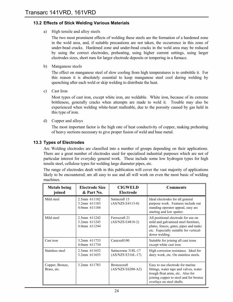
13.3 Types of Electrodes Arc Welding electrodes are classified into a number of groups depending on their applications. There are a great number of electrodes used for specialised industrial purposes which are not of particular interest for everyday general work. These include some low hydrogen types for high tensile steel, cellulose types for welding large diameter pipes, etc. The range of electrodes dealt with in this publication will cover the vast majority of applications likely to be encountered; are all easy to use and all will work on even the most basic of welding machines.
Metals being joined
Electrode Size & Part No.
CIGWELD Electrode
Comments
Mild steel 2.5mm 611182 3.2mm 611183 4.0mm 611184
Satincraft 13 (AS/NZS E4113-0)
Ideal electrodes for all general purpose work. Features include out standing operator appeal, easy arc starting and low spatter.
Mild steel 2.5mm 611242 3.2mm 611243 4.0mm 611244
Ferrocraft 21 (AS/NZS E4818-2)
All positional electrode for use on mild and galvanised steel furniture, plates, fences, gates, pipes and tanks etc. Especially suitable for vertical-down welding.
Cast iron 3.2mm 611733 4.0mm 611734
Castcraft100 Suitable for joining all cast irons except white cast iron.
Stainless steel 2.5mm 611652 3.2mm 611653
Satincrome 318L-17 (AS/NZS E316L-17)
High corrosion resistance. Ideal for dairy work, etc. On stainless steels.
Copper, Bronze, Brass, etc.
3.2mm 611783
Bronzecraft (AS/NZS E6200-A2)
Easy to use electrode for marine fittings, water taps and valves, water trough float arms, etc. Also for joining copper to steel and for bronze overlays on steel shafts.
Transarc 141VRD, 161VRD
25
Metals being joined
Electrode Size & Part No.
CIGWELD Electrode
Comments
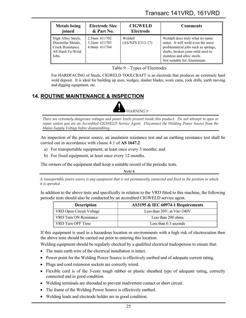
High Alloy Steels, Dissimilar Metals, Crack Resistance. All Hard-To-Weld Jobs.
2.5mm 611702 3.2mm 611703 4.0mm 611704
Weldall (AS/NZS E312-17)
Weldall does truly what its name states. It will weld even the most problematical jobs such as springs, shafts, broken joins mild steel to stainless and alloy steels. Not suitable for Aluminium.
Table 9 – Types of Electrodes For HARDFACING of Steels, CIGWELD TOOLCRAFT is an electrode that produces an extremely hard weld deposit. It is ideal for building up axes, wedges, slasher blades, worn cams, rock drills, earth moving and digging equipment, etc.
14. ROUTINE MAINTENANCE & INSPECTION
WARNING 9
There are extremely dangerous voltages and power levels present inside this product. Do not attempt to open or repair unless you are an Accredited CIGWELD Service Agent. Disconnect the Welding Power Source from the Mains Supply Voltage before disassembling.
An inspection of the power source, an insulation resistance test and an earthing resistance test shall be carried out in accordance with clause 4.1 of AS 1647.2
a) For transportable equipment, at least once every 3 months; and b) For fixed equipment, at least once every 12 months.
The owners of the equipment shall keep a suitable record of the periodic tests. Note 6
A transportable power source is any equipment that is not permanently connected and fixed in the position in which it is operated.
In addition to the above tests and specifically in relation to the VRD fitted to this machine, the following periodic tests should also be conducted by an accredited CIGWELD service agent.
Description AS3195 & IEC 60974-1 Requirements VRD Open Circuit Voltage Less than 20V; at Vin=240V VRD Turn ON Resistance Less than 200 ohms VRD Turn OFF Time Less than 0.3 seconds
If this equipment is used in a hazardous location or environments with a high risk of electrocution then the above tests should be carried out prior to entering this location. Welding equipment should be regularly checked by a qualified electrical tradesperson to ensure that: • The main earth wire of the electrical installation is intact. • Power point for the Welding Power Source is effectively earthed and of adequate current rating. • Plugs and cord extension sockets are correctly wired. • Flexible cord is of the 3-core tough rubber or plastic sheathed type of adequate rating, correctly
connected and in good condition. • Welding terminals are shrouded to prevent inadvertent contact or short circuit. • The frame of the Welding Power Source is effectively earthed. • Welding leads and electrode holder are in good condition.
Transarc 141VRD, 161VRD
26
• The Welding Power Source is clean internally, especially from metal filing, slag, and loose material. If any parts are damaged for any reason, replacement is recommended.
15. BASIC TROUBLESHOOTING
WARNING 10
There are extremely dangerous voltages and power levels present inside this product. Do not attempt to open or repair unless you are a qualified electrical tradesperson and you have had training in power measurements and troubleshooting techniques.
If major complex subassemblies are faulty, then the Welding Power Source must be returned to an Accredited CIGWELD Service Agent for repair.
The basic level of troubleshooting is that which can be performed without special equipment or knowledge.
15.1 TIG Welding Problems FAULT POSSIBLE CAUSE REMEDY
1 Electrode melts when arc is struck.
Electrode is connected to the ‘+’ terminal.
Connect the electrode to the ‘−’ terminal.
2 Dirty weld pool. A Electrode contaminated through contact with work piece or filler rod material.
A Clean the electrode by grinding off the contaminates.
B Gas contaminated with air. B Check gas lines for cuts and loose fitting or change gas cylinder.
3 Electrode melts or oxidises when an arc is struck.
A No gas flowing to welding region. A Check the gas lines for kinks or breaks and gas cylinder contents.
B Torch is clogged with dust. B Clean torch C Gas hose is cut. C Replace gas hose. D Gas passage contains impurities. D Disconnect gas hose from torch
then raise gas pressure and blow out impurities.
E Gas regulator turned off. E Turn on. F Torch valve is turned off. F Turn on. G The electrode is too small for the
welding current. G Increase electrode diameter or
reduce the welding current.
4 Poor weld finish. Inadequate shielding gas. Increase gas flow or check gas line for gas flow problems.
5 Arc flutters during TIG welding.
Tungsten electrode is too large for the welding current.
Select the right size electrode. Refer to Table 3.
6 Welding arc can not be established.
A Work clamp is not connected to the work piece or the work/torch leads are not connected to the right welding terminals.
A Connect the work clamp to the work piece or connect the work/torch leads to the right welding terminals.
B Torch lead is disconnected. B Connect it to the ‘−‘ terminal. C Gas flow incorrectly set, cylinder
empty or the torch valve is off. C Select the right flow rate, change
cylinders or turn torch valve on.
Transarc 141VRD, 161VRD
27
FAULT POSSIBLE CAUSE REMEDY
7 Arc start is not smooth.
A Tungsten electrode is too large for the welding current.
A Select the right size electrode. Refer to Table 3.
B The wrong electrode is being used for the welding job
B Select the right electrode type. Refer to Table 4.
C Gas flow rate is too high. C Select the correct rate for the welding job. Refer to Table 3.
D Incorrect shielding gas is being used.
D Select the right shielding gas. Refer to Table 6.
E Poor work clamp connection to work piece.
E Improve connection to work piece.
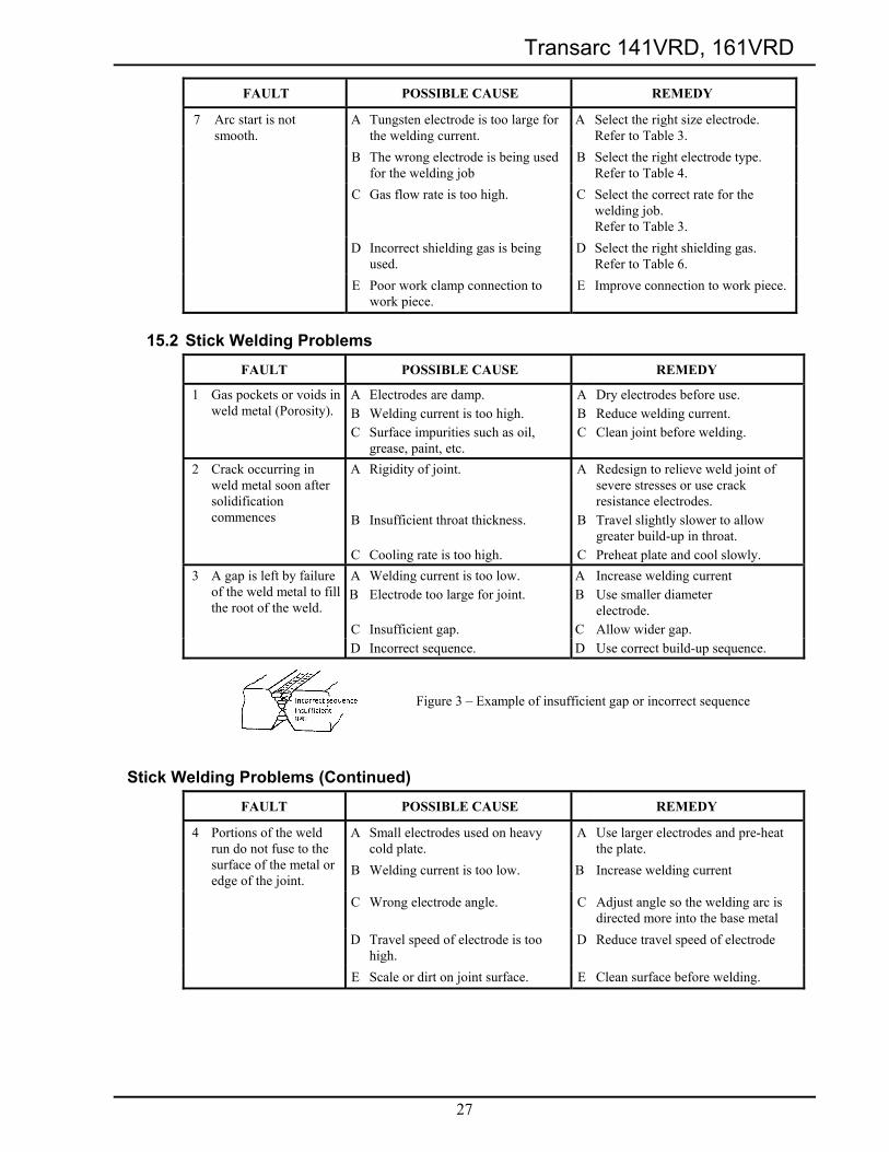
15.2 Stick Welding Problems FAULT POSSIBLE CAUSE REMEDY
1 Gas pockets or voids in weld metal (Porosity).
ABC
Electrodes are damp. Welding current is too high. Surface impurities such as oil, grease, paint, etc.
ABC
Dry electrodes before use. Reduce welding current. Clean joint before welding.
2 Crack occurring in weld metal soon after solidification commences
A
B
C
Rigidity of joint. Insufficient throat thickness. Cooling rate is too high.
A
B
C
Redesign to relieve weld joint of severe stresses or use crack resistance electrodes. Travel slightly slower to allow greater build-up in throat. Preheat plate and cool slowly.
3 A gap is left by failure of the weld metal to fill the root of the weld.
AB C
Welding current is too low. Electrode too large for joint. Insufficient gap.
A B C
Increase welding current Use smaller diameter electrode. Allow wider gap.
D Incorrect sequence. D Use correct build-up sequence.
Figure 3 – Example of insufficient gap or incorrect sequence
Stick Welding Problems (Continued) FAULT POSSIBLE CAUSE REMEDY
4 Portions of the weld run do not fuse to the surface of the metal or edge of the joint.
A
B
Small electrodes used on heavy cold plate. Welding current is too low.
A
B
Use larger electrodes and pre-heat the plate. Increase welding current
C Wrong electrode angle. C Adjust angle so the welding arc is directed more into the base metal
D Travel speed of electrode is too high.
D Reduce travel speed of electrode
E Scale or dirt on joint surface. E Clean surface before welding.
Transarc 141VRD, 161VRD
28
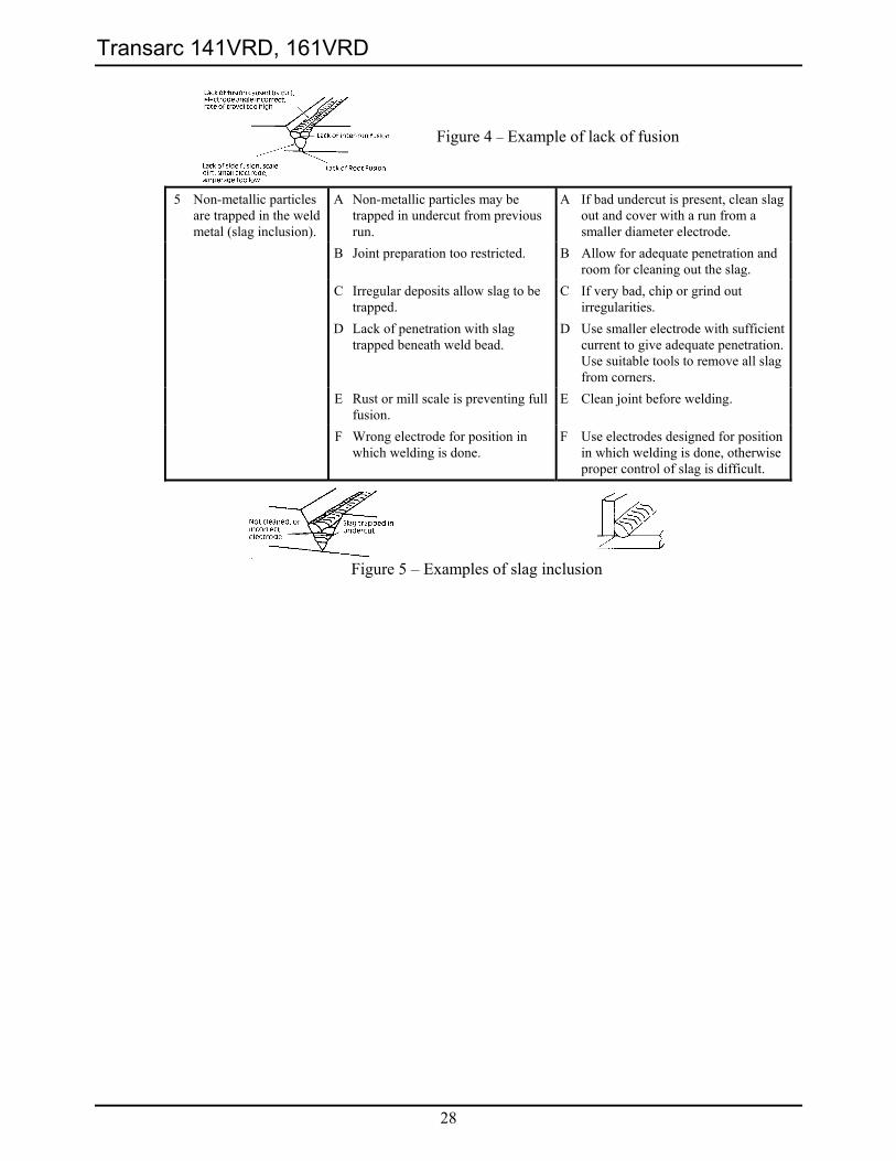
Figure 4 – Example of lack of fusion
5 Non-metallic particles are trapped in the weld metal (slag inclusion).
A Non-metallic particles may be trapped in undercut from previous run.
A If bad undercut is present, clean slag out and cover with a run from a smaller diameter electrode.
B Joint preparation too restricted. B Allow for adequate penetration and room for cleaning out the slag.
C Irregular deposits allow slag to be trapped.
C If very bad, chip or grind out irregularities.
D Lack of penetration with slag trapped beneath weld bead.
D Use smaller electrode with sufficient current to give adequate penetration. Use suitable tools to remove all slag from corners.
E Rust or mill scale is preventing full fusion.
E Clean joint before welding.
F Wrong electrode for position in which welding is done.
F Use electrodes designed for position in which welding is done, otherwise proper control of slag is difficult.
Figure 5 – Examples of slag inclusion
Transarc 141VRD, 161VRD
29
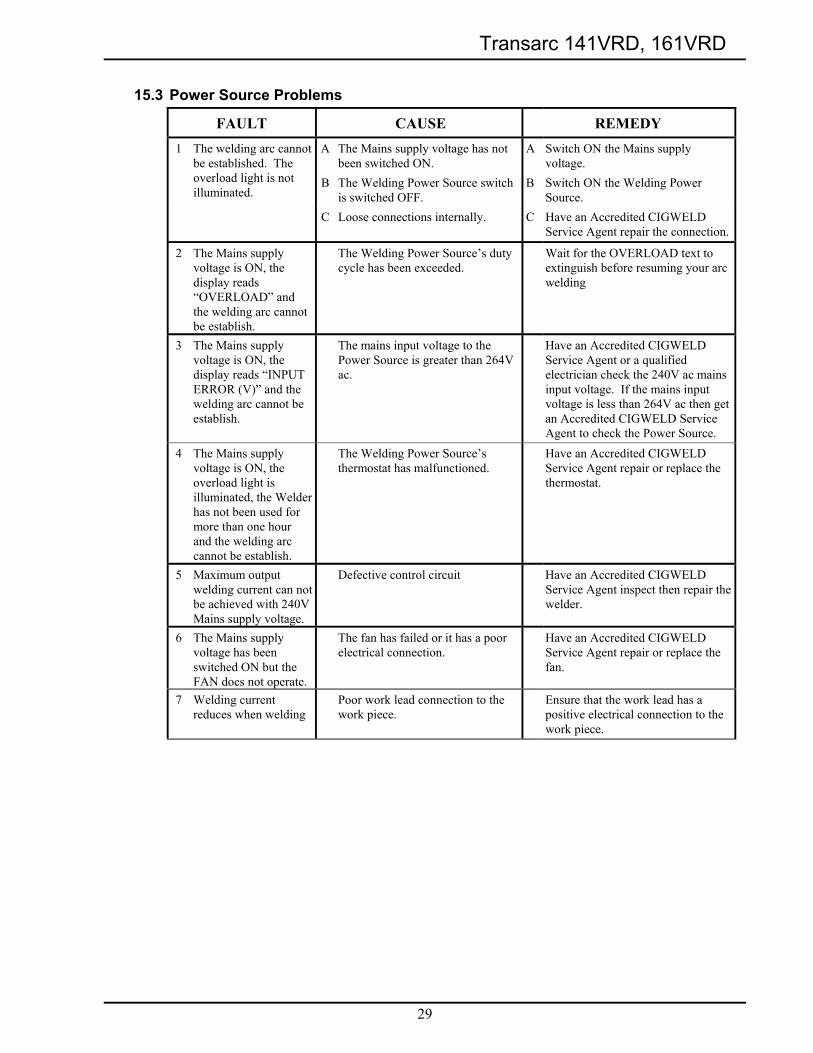
15.3 Power Source Problems
FAULT CAUSE REMEDY 1 The welding arc cannot
be established. The overload light is not illuminated.
A
B
The Mains supply voltage has not been switched ON. The Welding Power Source switch is switched OFF.
A B
Switch ON the Mains supply voltage. Switch ON the Welding Power Source.
C Loose connections internally. C Have an Accredited CIGWELD Service Agent repair the connection.
2 The Mains supply voltage is ON, the display reads “OVERLOAD” and the welding arc cannot be establish.
The Welding Power Source’s duty cycle has been exceeded.
Wait for the OVERLOAD text to extinguish before resuming your arc welding
3 The Mains supply voltage is ON, the display reads “INPUT ERROR (V)” and the welding arc cannot be establish.
The mains input voltage to the Power Source is greater than 264V ac.
Have an Accredited CIGWELD Service Agent or a qualified electrician check the 240V ac mains input voltage. If the mains input voltage is less than 264V ac then get an Accredited CIGWELD Service Agent to check the Power Source.
4 The Mains supply voltage is ON, the overload light is illuminated, the Welder has not been used for more than one hour and the welding arc cannot be establish.
The Welding Power Source’s thermostat has malfunctioned.
Have an Accredited CIGWELD Service Agent repair or replace the thermostat.
5 Maximum output welding current can not be achieved with 240V Mains supply voltage.
Defective control circuit Have an Accredited CIGWELD Service Agent inspect then repair the welder.
6 The Mains supply voltage has been switched ON but the FAN does not operate.
The fan has failed or it has a poor electrical connection.
Have an Accredited CIGWELD Service Agent repair or replace the fan.
7 Welding current reduces when welding
Poor work lead connection to the work piece.
Ensure that the work lead has a positive electrical connection to the work piece.


![Kake awacenter a egawa-center@ya oo.co.jp 0537-64-3072 … · 2019. 1. 22. · Kake awacenter a egawa-center@ya oo.co.jp 0537-64-3072 welcla , aaa . sp. E] It -EKED . Created Date:](https://img.pdfslide.us/doc/110x75/60fcc23e81185f58241a643f/kake-awacenter-a-egawa-centerya-oocojp-0537-64-3072-2019-1-22-kake-awacenter.jpg)