Embed Size (px)
Citation preview
Trajexia machine control systemTJ2-MC64, TJ2-MC02
PROGRAMMING MANUAL
Austria
Tel: +43 (0) 2236 377 800www.industrial.omron.at
Belgium
Tel: +32 (0) 2 466 24 80www.industrial.omron.be
Czech Republic
Tel: +420 234 602 602www.industrial.omron.cz
Denmark
Tel: +45 43 44 00 11www.industrial.omron.dk
Finland
Tel: +358 (0) 207 464 200www.industrial.omron.fi
France
Tel: +33 (0) 1 56 63 70 00www.industrial.omron.fr
Germany
Tel: +49 (0) 2173 6800 0www.industrial.omron.de
Hungary
Tel: +36 1 399 30 50www.industrial.omron.hu
Italy
Tel: +39 02 326 81www.industrial.omron.it
Netherlands
Tel: +31 (0) 23 568 11 00www.industrial.omron.nl
Norway
Tel: +47 (0) 22 65 75 00www.industrial.omron.no
Poland
Tel: +48 22 645 78 60www.industrial.omron.pl
Portugal
Tel: +351 21 942 94 00www.industrial.omron.pt
Russia
Tel: +7 495 648 94 50www.industrial.omron.ru
South-Africa
Tel: +27 (0)11 579 2600www.industrial.omron.co.za
Spain
Tel: +34 913 777 900www.industrial.omron.es
Sweden
Tel: +46 (0) 8 632 35 00www.industrial.omron.se
Switzerland
Tel: +41 (0) 41 748 13 13www.industrial.omron.ch
Turkey
Tel: +90 212 467 30 00www.industrial.omron.com.tr
United Kingdom
Tel: +44 (0) 870 752 08 61www.industrial.omron.co.uk
OMRON EUROPE B.V. Wegalaan 67-69, NL-2132 JD, Hoofddorp, The Netherlands. Tel: +31 (0) 23 568 13 00 Fax: +31 (0) 23 568 13 88 www.industrial.omron.eu
Authorised Distributor:
Note:Although we do strive for perfection, Omron Europe BV and/or its subsidiary and affiliated companies do not warrant or make any representations regarding the correctness or completeness of information described in this catalogue. Product information in this catalogue is provided ‚as is‘ without warranty of any kind, either express or implied, including, but not limited to, the implied warranties of merchantability, fitness for a particular purpose, or non-infringement. In a jurisdiction where the exclusion of implied warranties is not valid, the exclusion shall be deemed to be replaced by such valid exclusion, which most closely matches the intent and purpose of the original exclusion. Omron Europe BV and/or its subsidiary and affiliated companies reserve the right to make any changes to the products, their specifications, data at its sole discretion at any time without prior notice. The material contained in this catalogue may be out of date and Omron Europe BV and/or its subsidiary and affiliated companies make no commitment to update such material.
Cat. No. I58E-EN-05
Trajexia machine control system PROGRAMMING MANUAL
Cat. No.I58E-EN-05
Cat. No.I58E-EN-05
PROG III
Revision 5.0
NotiOMRby a qThe fthis mheed
Defi
TradPROFMECHEther(GermDevicCIP isCANoModbTrajeAll othtioned
publication may be reproduced, stored in a retrieval sys-r by any means, mechanical, electronic, photocopying, e prior written permission of OMRON. respect to the use of the information contained herein. nstantly striving to improve its high-quality products, the al is subject to change without notice. Every precaution of this manual. Nevertheless, OMRON assumes no s. Neither is any liability assumed for damages resulting tained in this publication.
RAMMING MANUAL
ceON products are manufactured for use according to proper procedures ualified operator and only for the purposes described in this manual.
ollowing conventions are used to indicate and classify precautions in anual. Always heed the information provided with them. Failure to precautions can result in injury to people or damage to property.
nition of precautionary information
emarks and CopyrightsIBUS is a registered trademark of PROFIBUS International.ATROLINK is a registered trademark of Yaskawa Corporation.
CAT is a registered trademark of Beckhoff Automation Gmbh any). EtherCAT technology is protected by patents.
eNet is a registered trademark of Open DeviceNet Vendor Assoc INC. a registered trademark of Open DeviceNet Vendor Assoc INC.pen is a registered trademark of CAN in Automation (CiA).usTCP is a registered trademark of Modbus IDA.xia is a registered trademark of OMRON.er product names, company names, logos or other designations men- herein are trademarks of their respective owners.
/i
WARNINGIndicates a potentially hazardous situation, which, if not avoided, could result in death or serious injury.
CAUTIONIndicates a potentially hazardous situation, which, if not avoided, may result in minor or moderate injury, or property damage.
© OMRON, 2012
All rights reserved. No part of this tem, or transmitted, in any form, orecording, or otherwise, without thNo patent liability is assumed withMoreover, because OMRON is coinformation contained in this manuhas been taken in the preparation responsibility for errors or omissionfrom the use of the information con
PROG IV
Revision 5.0
AboThis mContrPleascarefuattemto rea/i
Name
Trajextrol syQUICGUID
TrajexcontroHARDEREN
TrajexcontroPROGMANU
Sigmamanu
SigmMECHinterfa
Sigmmanu
JUNMdrive
V7 In
55 1-OY Describes the installation and operation of F7Z Inverters
60 Describes the installation and operation of G7 Inverters
80001 Describes the installation and operation of the MECHATROLINK-II application module
600-08 Describes the installation and operation of MECHATROLINK-II interfaces for G7 and F7 Inverters
600-03 Describes the installation and operation of MECHATROLINK-II interfaces for V7 Inverters
Describes the installation and operation of MECHATROLINK-II input and output modules and the MECHATROLINK-II repeater
Describes FINS communications proto-col and FINS commands
Describes the installation and operation of Omron slice I/O units
Describes the installation and operation of G-series Servo Drives
Describes the installation and operation of Accurax Servo Drives
Describes the use of Trajexia Studio programming software
Describes the installation and operation of Accurax EtherCAT Servo Drives
Contents
RAMMING MANUAL
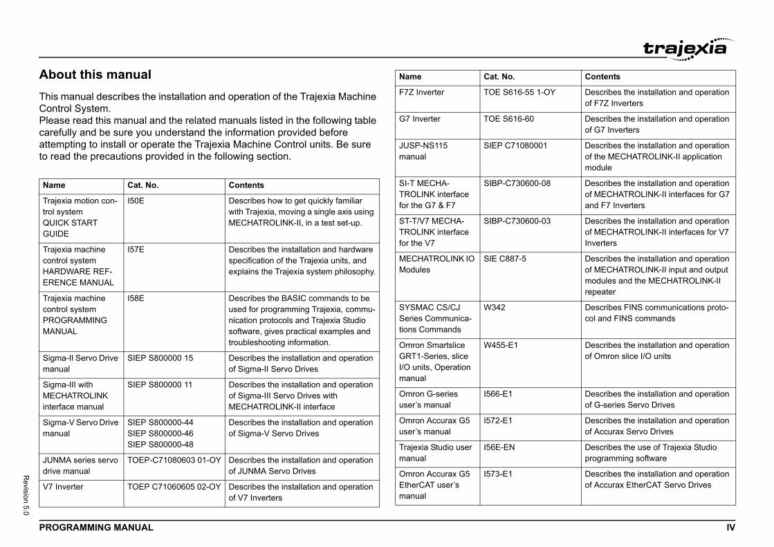
ut this manualanual describes the installation and operation of the Trajexia Machine
ol System.e read this manual and the related manuals listed in the following table lly and be sure you understand the information provided before pting to install or operate the Trajexia Machine Control units. Be sure d the precautions provided in the following section.
Cat. No. Contents
ia motion con-stemK START E
I50E Describes how to get quickly familiar with Trajexia, moving a single axis using MECHATROLINK-II, in a test set-up.
ia machine l system WARE REF-CE MANUAL
I57E Describes the installation and hardware specification of the Trajexia units, and explains the Trajexia system philosophy.
ia machine l systemRAMMING AL
I58E Describes the BASIC commands to be used for programming Trajexia, commu-nication protocols and Trajexia Studio software, gives practical examples and troubleshooting information.
-II Servo Drive al
SIEP S800000 15 Describes the installation and operation of Sigma-II Servo Drives
a-III with ATROLINK ce manual
SIEP S800000 11 Describes the installation and operation of Sigma-III Servo Drives with MECHATROLINK-II interface
a-V Servo Drive al
SIEP S800000-44SIEP S800000-46SIEP S800000-48
Describes the installation and operation of Sigma-V Servo Drives
A series servo manual
TOEP-C71080603 01-OY Describes the installation and operation of JUNMA Servo Drives
verter TOEP C71060605 02-OY Describes the installation and operation of V7 Inverters
F7Z Inverter TOE S616-
G7 Inverter TOE S616-
JUSP-NS115 manual
SIEP C710
SI-T MECHA-TROLINK interface for the G7 & F7
SIBP-C730
ST-T/V7 MECHA-TROLINK interface for the V7
SIBP-C730
MECHATROLINK IO Modules
SIE C887-5
SYSMAC CS/CJ Series Communica-tions Commands
W342
Omron Smartslice GRT1-Series, slice I/O units, Operation manual
W455-E1
Omron G-series user’s manual
I566-E1
Omron Accurax G5 user’s manual
I572-E1
Trajexia Studio user manual
I56E-EN
Omron Accurax G5 EtherCAT user’s manual
I573-E1
Name Cat. No.
PROG V
Revision 5.0
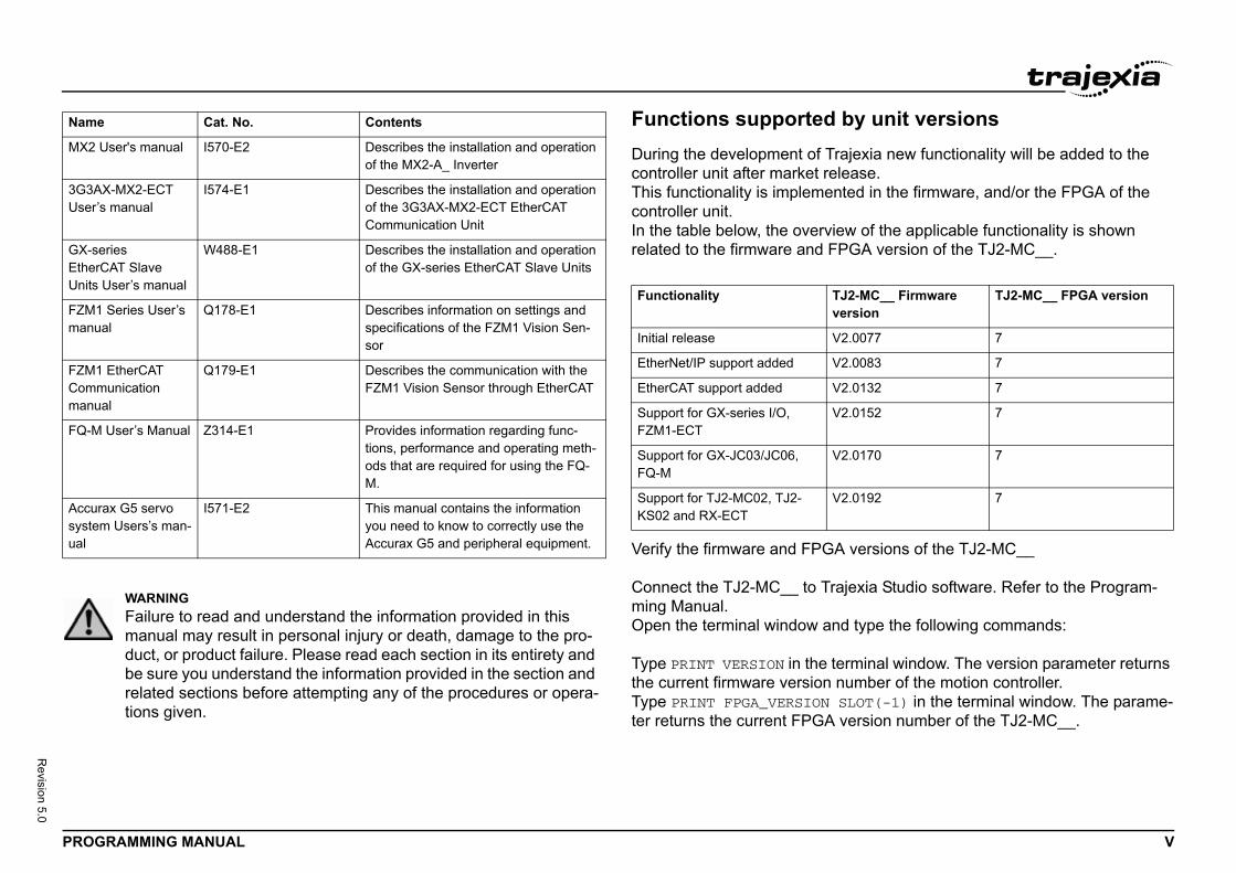
by unit versionsajexia new functionality will be added to the lease.ted in the firmware, and/or the FPGA of the
ew of the applicable functionality is shown PGA version of the TJ2-MC__.
versions of the TJ2-MC__
ajexia Studio software. Refer to the Program-
d type the following commands:
erminal window. The version parameter returns number of the motion controller.SLOT(-1) in the terminal window. The parame- version number of the TJ2-MC__.
MX2
3G3AUser’
GX-seEtherUnits
FZM1manu
FZM1Commmanu
FQ-M
Accursysteual
Name
J2-MC__ Firmware ersion
TJ2-MC__ FPGA version
2.0077 7
2.0083 7
2.0132 7
2.0152 7
2.0170 7
2.0192 7
RAMMING MANUAL
Functions supportedDuring the development of Trcontroller unit after market reThis functionality is implemencontroller unit.In the table below, the overvirelated to the firmware and F/i
Verify the firmware and FPGA
Connect the TJ2-MC__ to Trming Manual.Open the terminal window an
Type PRINT VERSION in the tthe current firmware version Type PRINT FPGA_VERSION ter returns the current FPGA
User's manual I570-E2 Describes the installation and operationof the MX2-A_ Inverter
X-MX2-ECT s manual
I574-E1 Describes the installation and operationof the 3G3AX-MX2-ECT EtherCAT Communication Unit
riesCAT Slave User’s manual
W488-E1 Describes the installation and operationof the GX-series EtherCAT Slave Units
Series User’s al
Q178-E1 Describes information on settings and specifications of the FZM1 Vision Sen-sor
EtherCAT unication
al
Q179-E1 Describes the communication with the FZM1 Vision Sensor through EtherCAT
User’s Manual Z314-E1 Provides information regarding func-tions, performance and operating meth-ods that are required for using the FQ-M.
ax G5 servo m Users’s man-
I571-E2 This manual contains the information you need to know to correctly use the Accurax G5 and peripheral equipment.
WARNINGFailure to read and understand the information provided in this manual may result in personal injury or death, damage to the pro-duct, or product failure. Please read each section in its entirety and be sure you understand the information provided in the section and related sections before attempting any of the procedures or opera-tions given.
Cat. No. Contents
Functionality Tv
Initial release V
EtherNet/IP support added V
EtherCAT support added V
Support for GX-series I/O, FZM1-ECT
V
Support for GX-JC03/JC06, FQ-M
V
Support for TJ2-MC02, TJ2-KS02 and RX-ECT
V
Conte
PROG VI
Revision 5.0
1 S . . . . . . . . . . . . . . . . . . . . . . . . . . . . . . . . 11 . . . . . . . . . . . . . . . . . . . . . . . . . . . . . . . . . . . . . . . 11 . . . . . . . . . . . . . . . . . . . . . . . . . . . . . . . . . . . . . . . 11 . . . . . . . . . . . . . . . . . . . . . . . . . . . . . . . . . . . . . . . 11 . . . . . . . . . . . . . . . . . . . . . . . . . . . . . . . . . . . . . . . 21 . . . . . . . . . . . . . . . . . . . . . . . . . . . . . . . . . . . . . . . 31 . . . . . . . . . . . . . . . . . . . . . . . . . . . . . . . . . . . . . . . 61 . . . . . . . . . . . . . . . . . . . . . . . . . . . . . . . . . . . . . . . 6
2 T . . . . . . . . . . . . . . . . . . . . . . . . . . . . . . . . 72 . . . . . . . . . . . . . . . . . . . . . . . . . . . . . . . . . . . . . . . 72 . . . . . . . . . . . . . . . . . . . . . . . . . . . . . . . . . . . . . . 102 . . . . . . . . . . . . . . . . . . . . . . . . . . . . . . . . . . . . . . 102 . . . . . . . . . . . . . . . . . . . . . . . . . . . . . . . . . . . . . . 152 . . . . . . . . . . . . . . . . . . . . . . . . . . . . . . . . . . . . . . 162 . . . . . . . . . . . . . . . . . . . . . . . . . . . . . . . . . . . . . . 16
3 B . . . . . . . . . . . . . . . . . . . . . . . . . . . . . . . 183 . . . . . . . . . . . . . . . . . . . . . . . . . . . . . . . . . . . . . . 183 . . . . . . . . . . . . . . . . . . . . . . . . . . . . . . . . . . . . . . 28
4 C . . . . . . . . . . . . . . . . . . . . . . . . . . . . . . 2374 . . . . . . . . . . . . . . . . . . . . . . . . . . . . . . . . . . . . . 2374 . . . . . . . . . . . . . . . . . . . . . . . . . . . . . . . . . . . . . 2374 . . . . . . . . . . . . . . . . . . . . . . . . . . . . . . . . . . . . . 2464 . . . . . . . . . . . . . . . . . . . . . . . . . . . . . . . . . . . . . 2544 . . . . . . . . . . . . . . . . . . . . . . . . . . . . . . . . . . . . . 2594 . . . . . . . . . . . . . . . . . . . . . . . . . . . . . . . . . . . . . 2644 . . . . . . . . . . . . . . . . . . . . . . . . . . . . . . . . . . . . . 2684 . . . . . . . . . . . . . . . . . . . . . . . . . . . . . . . . . . . . . 2684 . . . . . . . . . . . . . . . . . . . . . . . . . . . . . . . . . . . . . 2754 . . . . . . . . . . . . . . . . . . . . . . . . . . . . . . . . . . . . . 279
5 E . . . . . . . . . . . . . . . . . . . . . . . . . . . . . . 2835 . . . . . . . . . . . . . . . . . . . . . . . . . . . . . . . . . . . . . 2835 . . . . . . . . . . . . . . . . . . . . . . . . . . . . . . . . . . . . . 333
nts
RAMMING MANUAL
afety warnings and precautions. . . . . . . . . . . . . . . . . . . . . . . . . . . . . . . . . . . . . . . . . . . . . . . ..1 Intended audience . . . . . . . . . . . . . . . . . . . . . . . . . . . . . . . . . . . . . . . . . . . . . . . . . . . . . . . . . . . . . . . . . . . . . . ..2 General precautions . . . . . . . . . . . . . . . . . . . . . . . . . . . . . . . . . . . . . . . . . . . . . . . . . . . . . . . . . . . . . . . . . . . . ..3 Safety precautions . . . . . . . . . . . . . . . . . . . . . . . . . . . . . . . . . . . . . . . . . . . . . . . . . . . . . . . . . . . . . . . . . . . . . . ..4 Operating environment precautions. . . . . . . . . . . . . . . . . . . . . . . . . . . . . . . . . . . . . . . . . . . . . . . . . . . . . . . . . ..5 Application precautions . . . . . . . . . . . . . . . . . . . . . . . . . . . . . . . . . . . . . . . . . . . . . . . . . . . . . . . . . . . . . . . . . . ..6 Unit assembly precautions. . . . . . . . . . . . . . . . . . . . . . . . . . . . . . . . . . . . . . . . . . . . . . . . . . . . . . . . . . . . . . . . ..7 Conformance to EC Directives Conformance . . . . . . . . . . . . . . . . . . . . . . . . . . . . . . . . . . . . . . . . . . . . . . . . . .
rajexia system . . . . . . . . . . . . . . . . . . . . . . . . . . . . . . . . . . . . . . . . . . . . . . . . . . . . . . . . . . . . . ..1 Introduction . . . . . . . . . . . . . . . . . . . . . . . . . . . . . . . . . . . . . . . . . . . . . . . . . . . . . . . . . . . . . . . . . . . . . . . . . . . ..2 Multitasking BASIC programming . . . . . . . . . . . . . . . . . . . . . . . . . . . . . . . . . . . . . . . . . . . . . . . . . . . . . . . . . . ..3 BASIC programming . . . . . . . . . . . . . . . . . . . . . . . . . . . . . . . . . . . . . . . . . . . . . . . . . . . . . . . . . . . . . . . . . . . . ..4 Motion execution . . . . . . . . . . . . . . . . . . . . . . . . . . . . . . . . . . . . . . . . . . . . . . . . . . . . . . . . . . . . . . . . . . . . . . . ..5 Command line interface. . . . . . . . . . . . . . . . . . . . . . . . . . . . . . . . . . . . . . . . . . . . . . . . . . . . . . . . . . . . . . . . . . ..6 BASIC programs . . . . . . . . . . . . . . . . . . . . . . . . . . . . . . . . . . . . . . . . . . . . . . . . . . . . . . . . . . . . . . . . . . . . . . . .
ASIC commands . . . . . . . . . . . . . . . . . . . . . . . . . . . . . . . . . . . . . . . . . . . . . . . . . . . . . . . . . . . ..1 Categories . . . . . . . . . . . . . . . . . . . . . . . . . . . . . . . . . . . . . . . . . . . . . . . . . . . . . . . . . . . . . . . . . . . . . . . . . . . . ..2 All BASIC commands . . . . . . . . . . . . . . . . . . . . . . . . . . . . . . . . . . . . . . . . . . . . . . . . . . . . . . . . . . . . . . . . . . . .
ommunication protocols . . . . . . . . . . . . . . . . . . . . . . . . . . . . . . . . . . . . . . . . . . . . . . . . . . . . ..1 Available interfaces . . . . . . . . . . . . . . . . . . . . . . . . . . . . . . . . . . . . . . . . . . . . . . . . . . . . . . . . . . . . . . . . . . . . . ..2 Ethernet . . . . . . . . . . . . . . . . . . . . . . . . . . . . . . . . . . . . . . . . . . . . . . . . . . . . . . . . . . . . . . . . . . . . . . . . . . . . . ..3 Serial protocol . . . . . . . . . . . . . . . . . . . . . . . . . . . . . . . . . . . . . . . . . . . . . . . . . . . . . . . . . . . . . . . . . . . . . . . . ..4 PROFIBUS . . . . . . . . . . . . . . . . . . . . . . . . . . . . . . . . . . . . . . . . . . . . . . . . . . . . . . . . . . . . . . . . . . . . . . . . . . . ..5 DeviceNet . . . . . . . . . . . . . . . . . . . . . . . . . . . . . . . . . . . . . . . . . . . . . . . . . . . . . . . . . . . . . . . . . . . . . . . . . . . . ..6 CANopen . . . . . . . . . . . . . . . . . . . . . . . . . . . . . . . . . . . . . . . . . . . . . . . . . . . . . . . . . . . . . . . . . . . . . . . . . . . . . ..7 MECHATROLINK-II . . . . . . . . . . . . . . . . . . . . . . . . . . . . . . . . . . . . . . . . . . . . . . . . . . . . . . . . . . . . . . . . . . ..8 GRT1-ML2 I/O mapping . . . . . . . . . . . . . . . . . . . . . . . . . . . . . . . . . . . . . . . . . . . . . . . . . . . . . . . . . . . . . . . . . ..9 EtherCAT . . . . . . . . . . . . . . . . . . . . . . . . . . . . . . . . . . . . . . . . . . . . . . . . . . . . . . . . . . . . . . . . . . . . . . . . . . . . . ..10 GRT1-ECT I/O mapping . . . . . . . . . . . . . . . . . . . . . . . . . . . . . . . . . . . . . . . . . . . . . . . . . . . . . . . . . . . . . . . . . .
xamples and tips . . . . . . . . . . . . . . . . . . . . . . . . . . . . . . . . . . . . . . . . . . . . . . . . . . . . . . . . . . . ..1 How-to’s. . . . . . . . . . . . . . . . . . . . . . . . . . . . . . . . . . . . . . . . . . . . . . . . . . . . . . . . . . . . . . . . . . . . . . . . . . . . . . ..2 Practical examples. . . . . . . . . . . . . . . . . . . . . . . . . . . . . . . . . . . . . . . . . . . . . . . . . . . . . . . . . . . . . . . . . . . . . . .
Conte
PROG VII
Revision 5.0
6 T . . . . . . . . . . . . . . . . . . . . . . . . . . . . . . 3586 . . . . . . . . . . . . . . . . . . . . . . . . . . . . . . . . . . . . . 3586 . . . . . . . . . . . . . . . . . . . . . . . . . . . . . . . . . . . . . 3586 . . . . . . . . . . . . . . . . . . . . . . . . . . . . . . . . . . . . . 3616 . . . . . . . . . . . . . . . . . . . . . . . . . . . . . . . . . . . . . 3626 . . . . . . . . . . . . . . . . . . . . . . . . . . . . . . . . . . . . . 3626 . . . . . . . . . . . . . . . . . . . . . . . . . . . . . . . . . . . . . 3636 . . . . . . . . . . . . . . . . . . . . . . . . . . . . . . . . . . . . . 3636 . . . . . . . . . . . . . . . . . . . . . . . . . . . . . . . . . . . . . 3666 . . . . . . . . . . . . . . . . . . . . . . . . . . . . . . . . . . . . . 3666 . . . . . . . . . . . . . . . . . . . . . . . . . . . . . . . . . . . . . 3666 . . . . . . . . . . . . . . . . . . . . . . . . . . . . . . . . . . . . . 369
A G . . . . . . . . . . . . . . . . . . . . . . . . . . . . . . 370A . . . . . . . . . . . . . . . . . . . . . . . . . . . . . . . . . . . . . 370A . . . . . . . . . . . . . . . . . . . . . . . . . . . . . . . . . . . . . 372
Revi . . . . . . . . . . . . . . . . . . . . . . . . . . . . . . 375
nts
RAMMING MANUAL
roubleshooting. . . . . . . . . . . . . . . . . . . . . . . . . . . . . . . . . . . . . . . . . . . . . . . . . . . . . . . . . . . . . ..1 Voltage and analysis tools . . . . . . . . . . . . . . . . . . . . . . . . . . . . . . . . . . . . . . . . . . . . . . . . . . . . . . . . . . . . . . . . ..2 TJ2-MC__ . . . . . . . . . . . . . . . . . . . . . . . . . . . . . . . . . . . . . . . . . . . . . . . . . . . . . . . . . . . . . . . . . . . . . . . . . . . . ..3 TJ1-PRT . . . . . . . . . . . . . . . . . . . . . . . . . . . . . . . . . . . . . . . . . . . . . . . . . . . . . . . . . . . . . . . . . . . . . . . . . . . . . ..4 TJ1-DRT . . . . . . . . . . . . . . . . . . . . . . . . . . . . . . . . . . . . . . . . . . . . . . . . . . . . . . . . . . . . . . . . . . . . . . . . . . . . . ..5 TJ1-CORT . . . . . . . . . . . . . . . . . . . . . . . . . . . . . . . . . . . . . . . . . . . . . . . . . . . . . . . . . . . . . . . . . . . . . . . . . . . . ..6 TJ1-ML__. . . . . . . . . . . . . . . . . . . . . . . . . . . . . . . . . . . . . . . . . . . . . . . . . . . . . . . . . . . . . . . . . . . . . . . . . . . . . ..7 GRT1-ML2 . . . . . . . . . . . . . . . . . . . . . . . . . . . . . . . . . . . . . . . . . . . . . . . . . . . . . . . . . . . . . . . . . . . . . . . . . . . . ..8 TJ1-FL02 . . . . . . . . . . . . . . . . . . . . . . . . . . . . . . . . . . . . . . . . . . . . . . . . . . . . . . . . . . . . . . . . . . . . . . . . . . . . . ..9 TJ2-ECT__ . . . . . . . . . . . . . . . . . . . . . . . . . . . . . . . . . . . . . . . . . . . . . . . . . . . . . . . . . . . . . . . . . . . . . . . . . . . ..10 GRT1-ECT. . . . . . . . . . . . . . . . . . . . . . . . . . . . . . . . . . . . . . . . . . . . . . . . . . . . . . . . . . . . . . . . . . . . . . . . . . . . ..11 TJ1-KS02. . . . . . . . . . . . . . . . . . . . . . . . . . . . . . . . . . . . . . . . . . . . . . . . . . . . . . . . . . . . . . . . . . . . . . . . . . . . . .
RT1-ML2 timing . . . . . . . . . . . . . . . . . . . . . . . . . . . . . . . . . . . . . . . . . . . . . . . . . . . . . . . . . . . . ..1 Timing concepts. . . . . . . . . . . . . . . . . . . . . . . . . . . . . . . . . . . . . . . . . . . . . . . . . . . . . . . . . . . . . . . . . . . . . . . . ..2 Examples . . . . . . . . . . . . . . . . . . . . . . . . . . . . . . . . . . . . . . . . . . . . . . . . . . . . . . . . . . . . . . . . . . . . . . . . . . . . . .
sion history . . . . . . . . . . . . . . . . . . . . . . . . . . . . . . . . . . . . . . . . . . . . . . . . . . . . . . . . . . . . . . . . .
Safety
PROG 1
Revision 5.0
1
1.1This m(electinstal
1.2The uspeciBeformanuaviatiotheron livrepre
1.3
e positive and negative terminals of the bat-tteries, disassemble them, deform them by r throw them into a fire.xplode, combust or leak liquid.
must be taken by the customer to ensure f incorrect, missing, or abnormal signals gnal lines, momentary power interruptions, or
sult in serious accidents.
uits, interlock circuits, limit circuits, and similar st be provided by the customer as external cir-Trajexia motion controller. sult in serious accidents.
utput (I/O power supply to the TJ2) is over-ited, the voltage may drop and result in the off.As a countermeasure for such problems, ures must be provided to ensure safety in the
go off due to overload of the output transistors untermeasure for such problems, external st be provided to ensure safety in the system.
warnings and precautions
RAMMING MANUAL
Safety warnings and precautions
Intended audienceanual is intended for personnel with knowledge of electrical systems
rical engineers or the equivalent) who are responsible for the design, lation and management of factory automation systems and facilities.
General precautionsser must operate the product according to the performance fications described in this manual.e using the product under conditions which are not described in the al or applying the product to nuclear control systems, railroad systems, on systems, vehicles, safety equipment, petrochemical plants, and systems, machines and equipment that can have a serious influence es and property if used improperly, consult your OMRON sentative.
Safety precautions
WARNINGDo not attempt to take the Unit apart and do not touch any of the internal parts while power is being supplied.Doing so may result in electrical shock.
WARNINGDo not touch any of the terminals or terminal blocks while power is being supplied.Doing so may result in electric shock.
WARNINGNever short-circuit thteries, charge the baapplying pressure, oThe batteries may e
WARNINGFail-safe measures safety in the event ocaused by broken siother causes. Not doing so may re
WARNINGEmergency stop circsafety measures mucuits, i.e., not in the Not doing so may re
WARNINGWhen the 24-VDC oloaded or short-circuoutputs being turnedexternal safety meassystem.
WARNINGThe TJ2 outputs will(protection). As a cosafety measures mu
Safety
PROG 2
Revision 5.0
ronment precautions
nit in any of the following locations. in malfunction, electric shock, or burning.t to direct sunlight.t to temperatures or humidity outside the
in the specifications.t to condensation as the result of severe erature.t to corrosive or flammable gases.t to dust (especially iron dust) or salts.t to exposure to water, oil, or chemicals.t to shock or vibration.
d sufficient countermeasures when installing ing locations.
sufficient measures may result in malfunction.t to static electricity or other forms of noise.t to strong electromagnetic fields.t to possible exposure to radioactivity.to power supplies.
nment of the TJ2 System can have a large ty and reliability of the system.environments can lead to malfunction, failure, able problems with the TJ2 System.perating environment is within the specified tion and remains within the specified condi-f the system.
warnings and precautions
RAMMING MANUAL
1.4 Operating enviWARNINGThe TJ2 will turn off the WDOG when its self-diagnosis function detects any error. As a countermeasure for such errors, external safety measures must be provided to ensure safety in the system.
WARNINGProvide safety measures in external circuits, i.e., not in the Trajexia Machine Controller (referred to as "TJ2"), in order to ensure safety in the system if an abnormality occurs due to mal-function of the TJ2 or another external factor affecting the TJ2 operation.Not doing so may result in serious accidents.
WARNINGDo not attempt to disassemble, repair, or modify any Units. Any attempt to do so may result in malfunction, fire, or electric shock.
CAUTIONConfirm safety at the destination unit before transferring a program to another unit or editing the memory.Doing either of these without confirming safety may result in injury.
CAUTIONPay careful attention to the polarity (+/-) when wiring the DC power supply.A wrong connection may cause malfunction of the system.
CAUTIONTighten the screws on the terminal block of the Power Supply Unit to the torque specified in this manual.Loose screws may result in burning or malfunction.
CAUTIONDo not operate the UDoing so may result- Locations subjec- Locations subjec
range specified - Locations subjec
changes in temp- Locations subjec- Locations subjec- Locations subjec- Locations subjec
CAUTIONTake appropriate ansystems in the followInappropriate and in- Locations subjec- Locations subjec- Locations subjec- Locations close
CAUTIONThe operating enviroeffect on the longeviImproper operating and other unforeseeMake sure that the oconditions at installations during the life o
Safety
PROG 3
Revision 5.0
1.5
tions between the IN and OUT port of is can result in changes of address and axes CAT slaves.
sconnect EtherCAT slaves while the system is o can result in unreliable communication.
er supply voltage specified in this manual. may result in malfunction or burning.
asures to ensure that the specified power with d frequency is supplied. Be particularly careful power supply is unstable. upply may result in malfunction.
kers and take other safety measures against ternal wiring.easures against short-circuiting may result in
to the Input Units in excess of the rated input
result in burning.
warnings and precautions
RAMMING MANUAL
Application precautions
WARNINGDo not start the system until you check that the axes are present and of the correct type.The numbers of the Flexible axes will change if MECHATROLINK-II network errors occur during start-up or if the MECHATROLINK-II network configuration changes.
WARNINGWhen using multiple TJ1-ML__ units, do not swap the MECHA-TROLINK-cables. This can result in different axis allocation. This can result in serious injury and/or significant damage.
WARNINGCheck the user program for proper execution before actually run-ning it in the Unit. Not checking the program may result in an unexpected operation.
WARNINGAXIS_OFFSET is fixed to a unit number. Changing the position of the attached units can therefore result in a different axis allocation. This can result in serious injury and/or significant damage.
WARNINGAlways connect the EtherCAT master port to the IN port of the first slave. Not doing so can result in unreliable communication and changes to address and axes assignment of EtherCAT slaves.
WARNINGDo not swap connecEtherCAT slaves. Thassignment of Ether
WARNINGDo not connect or dioperational. Doing s
CAUTIONAlways use the powAn incorrect voltage
CAUTIONTake appropriate methe rated voltage anin places where the An incorrect power s
CAUTIONInstall external breashort-circuiting in exInsufficient safety mburning.
CAUTIONDo not apply voltagevoltage. Excess voltage may
Safety
PROG 4
Revision 5.0
ctive label attached to the Unit when wiring. rotective label may result in malfunction.
otective label after the completion of wiring to dissipation. tective label attached may result in malfunc-
for wiring. Do not connect bare stranded wires stranded wires may result in burning.
wiring before turning on the power supply. result in burning.
result in burning.
after checking the terminal block completely.
inal blocks, expansion cables, and other vices are properly locked into place. y result in malfunction.
warnings and precautions
RAMMING MANUAL
CAUTIONDo not apply voltage or connect loads to the Output Units in excess of the maximum switching capacity. Excess voltage or loads may result in burning.
CAUTIONDisconnect the functional ground terminal when performing with-stand voltage tests. Not disconnecting the functional ground terminal may result in burning.
CAUTIONAlways connect to a class-3 ground (to 100Ω or less) when install-ing the Units. Not connecting to a class-3 ground may result in electric shock.
CAUTIONAlways turn off the power supply to the system before attempting any of the following. Not turning off the power supply may result in malfunction or elec-tric shock.- Mounting or dismounting expansion Units, CPU Units, or any
other Units.- Assembling the Units.- Setting dipswitches or rotary switches.- Connecting or wiring the cables.- Connecting or disconnecting the connectors.
CAUTIONBe sure that all mounting screws, terminal screws, and cable con-nector screws are tightened to the torque specified in this manual.Incorrect tightening torque may result in malfunction.
CAUTIONLeave the dust proteRemoving the dust p
CAUTIONRemove the dust prensure proper heat Leaving the dust protion.
CAUTIONUse crimp terminalsdirectly to terminals.Connection of bare
CAUTIONDouble-check all theIncorrect wiring may
CAUTIONWire correctly. Incorrect wiring may
CAUTIONMount the Unit only
CAUTIONBe sure that the termitems with locking deImproper locking ma
Safety
PROG 5
Revision 5.0
shielded. In environments that are subject to with shielded twisted-pair (STP) cable and FA environment. -pair cables with high-voltage lines.-pair cables near devices that generate noise.-pair cables in locations that are subject to
-pair cables in locations subject to excessive l mist or other contaminants.
onnecting cables specified in operation manu-nits.sult in malfunction of the system.
on due to a malfunction in the built-in transis-internal circuits.As a countermeasure for such afety measures must be provided to ensure tem.
erating in RUN mode when the power is ASIC program is set to Auto Run mode.
tatus-Words” of each GRT1-ML2 and ice coupler.d to missing or incorrect I/O data.
warnings and precautions
RAMMING MANUAL
CAUTIONConfirm that no adverse effect will occur in the system before changing the operating mode of the system. Not doing so may result in an unexpected operation.
CAUTIONResume operation only after transferring to the new CPU Unit the contents of the VR and table memory required for operation. Not doing so may result in an unexpected operation.
CAUTIONWhen replacing parts, be sure to confirm that the rating of a new part is correct. Not doing so may result in malfunction or burning.
CAUTIONDo not pull on the cables or bend the cables beyond their natural limit. Doing so may break the cables.
CAUTIONBefore touching the system, be sure to first touch a grounded metallic object in order to discharge any static build-up. Otherwise it might result in a malfunction or damage.
CAUTIONUTP cables are not noise use a system hubs suitable for anDo not install twistedDo not install twistedDo not install twistedhigh humidity.Do not install twisteddirt and dust or to oi
CAUTIONUse the dedicated cals to connect the UNot doing so may re
CAUTIONOutputs may remaintor outputs or other problems, external sthe safety of the sys
CAUTIONThe TJ2 will start opturned on and if a B
CAUTIONAlways check the “SGRT1-ECT SmartSlNot doing so can lea
Safety
PROG 6
Revision 5.0
precautions
o EC Directives Conformance
s EMC and Low Voltage are as follows:
with EC Directives also conform to the related can be more easily built into other devices or ts have been checked for conformity to EMC ucts conform to the standards in the system er, must be checked by the customer.
the OMRON devices that comply with EC g on the configuration, wiring, and other r control panel in which the OMRON devices ust, therefore, perform final checks to confirm
machine conform to EMC standards.
perating at voltages of 50 to 1,000 VAC or 75 to safety standards.
rly. of the unit may result in malfunction.
e Termination Unit supplied with the ht most Unit.ion Unit is properly mounted, the TJ2 will not
warnings and precautions
RAMMING MANUAL
1.6 Unit assembly
1.7 Conformance t
1.7.1 Concepts
The concepts for the directive
EMC DirectivesOMRON devices that complyEMC standards so that they machines. The actual producstandards. Whether the prodused by the customer, howevEMC-related performance ofDirectives will vary dependinconditions of the equipment oare installed. The customer mthat devices and the over-all
Low Voltage DirectiveAlways ensure that devices o1,500 VDC meet the required
CAUTIONAlways check the status of the connected MECHATROLINK-II devices in a BASIC program.Not doing so may result in an unexpected operation.
CAUTIONThe TJ1-CORT unit is developed to exchange I/O data between the Trajexia system and a CANopen network. The TJ1-CORT is not able to exchange motion commands.Using the TJ1-CORT to exchange motion commands may result in unexpected operation.
CAUTIONAlthough the TJ2-MC__ in most cases is backwards compatible with TJ1-MC__, applications written for TJ1-MC__ must be tested carefully when running on TJ2-MC__.Not doing so may result in unexpected operation.
CAUTIONWhen using multiple TJ1-ML__ units, do not swap the MECHA-TROLINK-cables. This can result in different axis allocation. This can result in serious injury and/or significant damage.
CAUTIONInstall the unit propeImproper installation
CAUTIONBe sure to mount thTJ2-MC__ to the rigUnless the Terminatfunction properly.
Trajex
PROG 7
Revision 5.0
2
2.1fig. 1Traje
the e
Trajescalacontrocam, comm
TrajeEtherpositiinstru
You cdrive 64 ax
The Tcontro
2.1.1
The TmanuThe T
CX-one ajexia Studio
PROFIBUS-DP Master
DEVICENET Master
CANopen Master
ia system
RAMMING MANUAL
Trajexia system
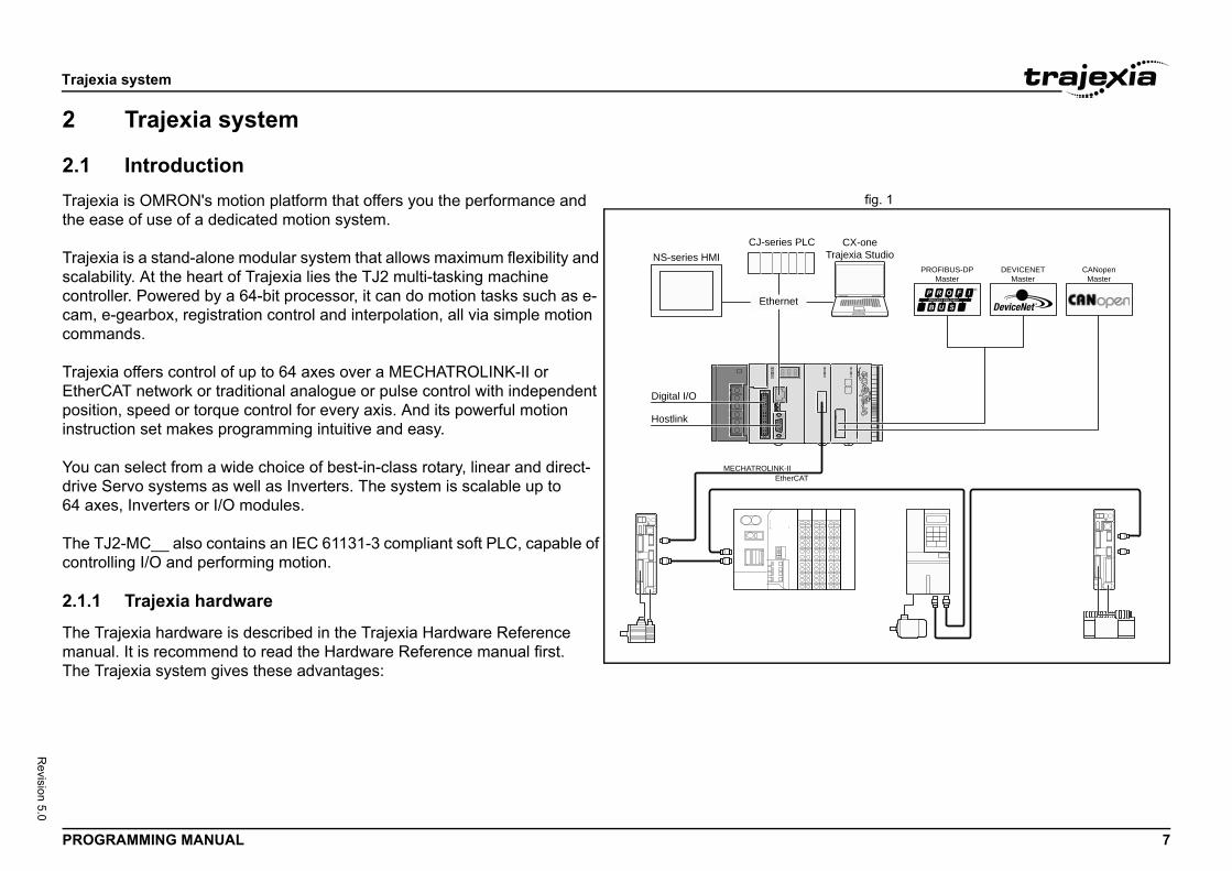
Introductionxia is OMRON's motion platform that offers you the performance and ase of use of a dedicated motion system.
xia is a stand-alone modular system that allows maximum flexibility and bility. At the heart of Trajexia lies the TJ2 multi-tasking machine ller. Powered by a 64-bit processor, it can do motion tasks such as e-
e-gearbox, registration control and interpolation, all via simple motion ands.
xia offers control of up to 64 axes over a MECHATROLINK-II or CAT network or traditional analogue or pulse control with independent on, speed or torque control for every axis. And its powerful motion ction set makes programming intuitive and easy.
an select from a wide choice of best-in-class rotary, linear and direct-Servo systems as well as Inverters. The system is scalable up to es, Inverters or I/O modules.
J2-MC__ also contains an IEC 61131-3 compliant soft PLC, capable of lling I/O and performing motion.
Trajexia hardware
rajexia hardware is described in the Trajexia Hardware Reference al. It is recommend to read the Hardware Reference manual first.rajexia system gives these advantages:
MECHATROLINK-II
Digital I/O
Hostlink
Ethernet
NS-series HMICJ-series PLC
Tr
EtherCAT
Trajex
PROG 8
Revision 5.0
DirecTrajePCs, and toexplicEthermakin
KeepBy prcomp
SeriaA serotherI/Os i
MECThe MInvertsysteaccurmotio
EtheEtherEthertransmsharinwith lThe EI/Os wmotio
nit)trol of two actuators via an analogue output or orts the main absolute encoder protocols external encoder to the system.
erial Interface Unit)trol of Servo Drives via a high-speed serial pports incremental and the main absolute e connection of an external encoder to the
r and direct-drive Servo systems as well as our needs in compactness, performance and ected to MECHATROLINK-II and EtherCAT are cle time as the Servo Drives.
LINK-II or EtherCAT network provide for ing the devices under one motion bus.
ows connectivity to the PROFIBUS network in
onnectivity to the DeviceNet network in your
connectivity to the CANopen network in your
nd ModbusTCP via Ethernet are supported to s supporting the same interface.
ia system
RAMMING MANUAL
t connectivity via Ethernetxia's built-in Ethernet interface provides direct and fast connectivity to PLCs, HMIs and other devices while providing full access to the CPU the Drives over a MECHATROLINK-II or EtherCAT network. It allows it messaging over Ethernet and through MECHATROLINK-II or CAT to provide full transparency down to the actuator level, and g remote access possible.
your know-how safeeventing access to the programs in the controller Trajexia guarantees lete protection and confidentiality for your valuable know-how.
l Port and Local I/Osial port provides direct connectivity with any OMRON PLC, HMIs or any field device. 16 Inputs and 8 outputs are freely configurable embedded n the controller to enable you to tailor Trajexia to your machine design.
HATROLINK-II MasterECHATROLINK-II master performs control of up to 16 Servo Drives,
ers or I/Os while allowing complete transparency across the whole m.MECHATROLINK-II offers the communication speed and time acy essential to guarantee perfect motion control of Servo Drives. The n cycle time is selectable between 0.5 ms, 1 ms or 2 ms.
rCAT MasterCAT is an open high-speed industrial network system that conforms to net (IEEE802.3). Each node achieves a short cycle time by
itting Ethernet frames at high speed. A mechanism that allows g clock information enables high-precision synchronization control
ow communications jitter.therCAT master performs control of up to 64 Servo Drives, Inverters or hile allowing complete transparency across the whole system. The
n cycle time is selectable between 0.25 ms, 0.5 ms, 1 ms or 2 ms.
TJ1-FL02 (Flexible Axis UThe TJ1-FL02 allows full conpulse train. The module suppallowing the connection of an
TJ2-KS02 (Accurax G5 SThe TJ2-KS02 allows full coninterface. The module also suencoder protocols allowing thsystem.
Drives and InvertersA wide choice of rotary, lineaInverters are available to fit yreliability. The Inverters conndriven at the same update cy
Remote I/OsThe I/Os on the MECHATROsystem expansion while keep
PROFIBUS-DP The PROFIBUS-DP slave allyour machine.
DeviceNetThe DeviceNet slave allows cmachine.
CANopenThe CANopen master allowsmachine.
ModbusBoth ModbusRTU via serial abe able to connect to master
Trajex
PROG 9
Revision 5.0
2.1.2
This P• T• T• T• P• T
ia system
RAMMING MANUAL
This manual
rogramming Manual gives the dedicated information for:he description and use of the BASIC commandshe communication protocols necessary for the Trajexia systemhe use and description of the parts of the Trajexia Studio interfacerogram examples and good programming practicesroubleshooting and fault finding.
Trajex
PROG 10
Revision 5.0
2.2The Tof thebasedtokenMultitto be over ethe loprogrThe TprogrcontroThe Bfound
2.3The BparamcontroCommactionthat won a cFunctactionthe vasome1, whstringParamvalueused ACCE
task statements
d parameters apply either to (one of) the axes, ral system.
s and the axis parameters apply to one or more ine and monitor how an axis reacts on
eacts to the outside world. Every axis has a set s can work independently of each other. The e able to control one or more of the axes xis has its own behaviour. The axis parameters es for each startup.ers work on some base axis or group of axes, and. The BASE command is used to change y task has its own group which can be changed axis is 0.mmands or parameters can also be
porary base axis by including the AXIS xis dependent command. A temporary base
ommand or parameter after which AXIS
a single task. The task parameters monitor the dling. The PROC modifier allows the user to
ain task. Without PROC the current task is nd (see above) is task specific and can be .
overall system features, which are basically all ng to the first two groups.
ia system
RAMMING MANUAL
Multitasking BASIC programmingJ2-MC__ units (Machine Controller Unit) feature a multitasking version BASIC programming language. The motion control language is largely upon a tokenised BASIC and the programs are compiled into the
ised form prior to their execution.asking is simple to set up and use and allows very complex machines programmed. Multitasking gives the TJ2-MC__ a significant advantage quivalent single task systems. It allows modular applications where
gically connected processes can be grouped together in the same task am, thus simplifying the code architecture and design.J2-MC__ can hold up to 32 programs if memory size permits. Up to 22 ams can be run simultaneously. The execution of the programs is user lled using BASIC.ASIC commands, functions and parameters presented here can be in chapter 3.
BASIC programmingASIC language consists among others of commands, functions and eters. These BASIC statements are the building blocks provided to l the TJ2-MC__ operation.ands are words recognized by the processor that perform a certain but do not return a value. For example, PRINT is a recognized word ill cause the value of the following functions or variables to be printed ertain output device.ions are words recognized by the processor that perform a certain and return a value related to that action. For example, ABS will take lue of its parameter and return the absolute value of it to be used by
other function or command. For example ABS(-1) will return the value ich can be used by the PRINT command, for example, to generate a to be output to a certain device.eters are words recognized by the processor that contain a certain
. This value can be read and, if not read only, written. Parameters are to determine and monitor the behaviour of the system. For example, L determines the acceleration rate of a movement for a certain axis.
2.3.1 Axis, system and
The commands, functions anthe tasks running or the gene
Axis statementsThe motion control commandaxes. Axis parameters determcommands given and how it rof parameters, so that all axemotion control commands arsimultaneously, while every aare reset to their default valuThe commands and parametspecified by the BASE commthis base axis group and everat any time. The default baseIndividual axis dependent coprogrammed to work on a temfunction as a modifier in the aaxis is effective only for the cappears.
Task statementsThe task parameters apply totask for example for error hanaccess a parameter of a certassumed. The BASE commaused with the PROC modifier
System statementsThese statements govern thestatements which do not belo
Trajex
PROG 11
Revision 5.0
2.3.2
ThreeUnit:• I/• V• TA
I/O mI/O mconnedigitaholds(inputthis maccesThe aIts cachannchann
VR mVR mwhichsameA meVR mWritinin theRAM prese
TABLTABLmeanWhergloba
to be arranged in a certain order. For this mmonly used for storing TABLE data, motion me BASIC commands that provide this type SCOPE, CAM, CAMBOX etc., require use of results. The size of this memory is 500,000 9. The TABLE is accessible for reading and cessed differs for those two operations. Before E memory slot needs to be defined and written LE(x, value1, value2,…) where x is the index
lot to define, and value1, value2, ... are the memory at indexes x, x+1, ... Once defined
ory slot can be read using the TABLE(x) ex of the TABLE memory slot. An attempt to mory slot results in an error reported by the ABLE memory entries are held in the battery
s preserved during power off. This part of the rved when changing the battery, if this is done
ia system
RAMMING MANUAL
Memory areas
main memory areas can be identified in the Trajexia Motion Controller
O memory.R memory.BLE memory.
emoryemory is used for holding the status of input and output devices cted to the Trajexia system. It is divided into two sub-areas: one for
l I/O memory, and one for analog I/O memory. The digital I/O memory input and output statuses of digital I/O devices. Its capacity is 1024 bits points) for input and 1024 bits (output points) for outputs. The inputs in emory can be accessed using the IN command. The outputs can be sed using the OUT command.nalog I/O memory holds input and output values of analog I/O devices. pacity is 36 input channels and 36 output channels. The analog input els can be accessed using the AIN command. The analog output els can be accessed using the AOUT command.
emoryemory is commonly used if some data or value needs to be global, means that it is accessible from all programs in the project at the time. The size of this memory is 64,000 slots with indexes 0 to 63,999. mory slot is addressed using the VR(x) macro where x is index of the emory slot. The VR memory is accessible for reading and writing. g is done by making mathematical assignment using the = command program. The content of this memory is held in the battery powered memory and is preserved during power off. The VR memory is also rved when changing the battery, if this is done quickly.
E memoryE is commonly used if some data or value needs to be global, which s that it is accessible from all programs in the project at the same time. eas the VR memory is used for similar purposes to define several l data and values, TABLE memory is used for much bigger amounts of
global data, which also needreason, TABLE memory is coprofiles, logging data, etc. Soand size of data, for exampleTABLE memory to write theirslots with indexes 0 to 499,99writing too, but the way it is acbeing read, a particular TABLfirst, using the command TABof the start TABLE memory svalues written into the TABLEand written, the TABLE memcommand, where x is the indread an undefined TABLE meTJ2-MC__. The first 65,536 Tpowered RAM memory and iTABLE memory is also presequickly.
Trajex
PROG 12
Revision 5.0
2.3.3
BASISomesystedefinethe Tlabels
TABLThe TnumbCAMexamproceThe TvalueTABLmaximTABLeleme
GlobThe gTJ2-Mcertaithat smoreto thevariabVR co
iables can be declared in programs and are that two or more programs running on different ble name, but their values can be different. d from any task except for the one in which bles are always cleared when a program is
an be cleared by using either the CLEAR or the
iables can be declared. Only the first e significant. Undefined local variables will annot be declared on the command line.
cuted in descending order through the lines. is execution flow using the BASIC commands e a label it must appear as the first statement d by a colon (:). Labels can be character strings t 32 characters are significant.
data can be accessed from the different run-ing either VR or TABLE variables, make sure to write to one particular variable. This to o program tasks writing unexpectedly to one
ia system
RAMMING MANUAL
Data structures and variables
C programs can store numerical data in various types of variables. variables have predefined functions, such as the axis parameters and m parameters; other variables are available for the programmer to as required in programming. The TABLE, global and local variables of
J2-MC__ are explained in this section. Furthermore also the use of will be specified.
E variablesABLE is an array structure that contains a series of numbers. These ers are used for instance to specify positions in the profile for a CAM or BOX command. They can also be used to store data for later use, for ple to store the parameters used to define a workpiece to be ssed.ABLE is common to all tasks on the TJ2-MC__. This means that the s written to the TABLE from one task can be read from other tasks.E values can be written and read using the TABLE command. The um length of the array is 500,000 elements, from TABLE(0) to
E(499999). The TABLE array is initialized up to the highest defined nt.
al variableslobal variables, defined in VR memory, are common to all tasks on the C__. This means that if a program running on task 2 sets VR(25) to a
n value, then any other program running on a different task can read ame value from VR(25). This is very useful for synchronizing two or tasks, but care must be taken to avoid more than one program writing same variable at the same time. The controller has 64,000 global les, VR(0) to VR(63999). The variables are read and written using the mmand.
Local variablesNamed variables or local varlocal to the task. This meanstasks can use the same variaLocal variables cannot be reathey are declared. Local variastarted. The local variables cRESET command.A maximum of 1024 local var32 characters of the name arreturn zero. Local variables c
LabelsThe BASIC programs are exeLabels can be used to alter thGOTO and GOSUB. To definon a line and it must be endeof any length, but only the firs
NOTEThe TABLE and VRning tasks. When usto use only one taskavoid problems of twvariable.
Trajex
PROG 13
Revision 5.0
UsinEachthe tw/i
Thesetheir oIf youvariabheld, To maapproconstdeclathe ecomm/i
The ocommvariab
ll other programs. Take care that the program nition must be run before the name is used in ctice is to define global names in the start-up , the example above becomes:
cifications
formats for numeric values: double precision cision integer. point format is internally a 64 bit value. It has n bit and a 52 bit fraction field. Floating point
of ±2.2×10−308 to ±1.8×10308.ng point numbers with a zero exponent. This 3 bits wide. The integer range is therefore 0,992 to 9,007,199,254,740,991. Numeric
be floating point.
star GOTO
star
Init
rt-up program
uted after the start-up program
start: MOVE(length) PRINT(length) ...
culations are done in floating point format. This lations of/with larger values the results may y. The user should be aware of this when n control application.
ia system
RAMMING MANUAL
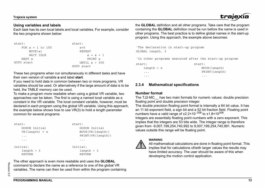
g variables and labels task has its own local labels and local variables. For example, consider o programs shown below:
two programs when run simultaneously in different tasks and have wn version of variable a and label start.
need to hold data in common between two or more programs, VR les should be used. Or alternatively if the large amount of data is to be
the TABLE memory can be used.ke a program more readable when using a global VR variable, two aches can be taken. The first is using a named local variable as a ant in the VR variable. The local constant variable, however, must be red in each program using the global VR variable. Using this approach, xample below shows how to use VR(3) to hold a length parameter on for several programs:
ther approach is even more readable and uses the GLOBAL and to declare the name as a reference to one of the global VR les. The name can then be used from within the program containing
the GLOBAL definition and acontaining the GLOBAL defiother programs. The best praprogram. Using this approach/i
2.3.4 Mathematical spe
Number formatThe TJ2-MC__ has two mainfloating point and double preThe double precision floatingan 11 bit exponent field, a signumbers have a valid range Integers are essentially floatiimplies that the integers are 5given from -9,007,199,254,74values outside this range will
t:FOR a = 1 to 100 MOVE(a) WAIT IDLENEXT a start
start: a=0 REPEAT a = a + 1 PRINT a UNTIL a = 300GOTO start
t:GOSUB InitialVR(length) = x......
ial:length = 3RETURN
start: GOSUB Initial MOVE(VR(length)) PRINT(VR(length)) ...
Initial: length = 3 RETURN
'The declaration in staGLOBAL length, 3
'In other programs exec
start: length = x ... ...
WARNINGAll mathematical calimplies that for calcuhave limited accuracdeveloping the motio
Trajex
PROG 14
Revision 5.0
HexaThe TA hexValid >> VR>> PR255.0A valuvalueis from>> TA>> PR1FFFF
PosiFor pdistanroundthe axcount
FloaThe cequalwhich
PrecThe p1. U2. ^3. / 4. M5. +6. =7. A8. L
recedence of various operators is through the
ia system
RAMMING MANUAL
decimal formatJ2-MC__ supports assigning and printing hexadecimal values. adecimal number is input by prefixing the number with the $ character. range is from 0x0 to 0xFFFFFFFFFFFFF. Example:(0)=$FFINT VR(0)000e can be printed in hexadecimal by using the HEX function. Negative
s result in the 2’s complement hexadecimal value (53-bit). Valid range -9,007,199,254,740,991 to 9,007,199,254,740,991. Example:BLE(0,-10,65536)INT HEX(TABLE(0)),HEX(TABLE(1))FFFFFFFF6 10000
tioningositioning, the TJ2-MC__ will round up if the fractional encoder edge ce calculated exceeds 0.9. Otherwise the fractional value will be ed down. The internal measured position and demanded position of es, represented by the MPOS and DPOS axis parameters, have 64-bit ers.
ting point comparisonomparison function considers a small difference between values as to avoid unexpected comparison results. Therefore any two values for the difference is less than 1.19×10⁻⁶ are considered equal.
edencerecedence of the operators is given below:nary minus, NOT
*OD - <> > >= <= <ND OR XOReft to right
The best way to ensure the puse of parentheses.
Trajex
PROG 15
Revision 5.0
2.4Everyfrom
2.4.1
The mOne bcurreNext See cmanu
The Bwhichfunctiown aindepspeciWhenthe mand t
fig. 2
MoveLoading
Sequencing
MotionGenerator
VE (1)VECIRC (4)
FORWARD (10)MOVECIRC (4)
IDLE (0)IDLE (0)
0 1 2
ia system
RAMMING MANUAL
Motion execution task on the TJ2-MC__ has a set of buffers that holds the information the motion commands given.
Motion generator
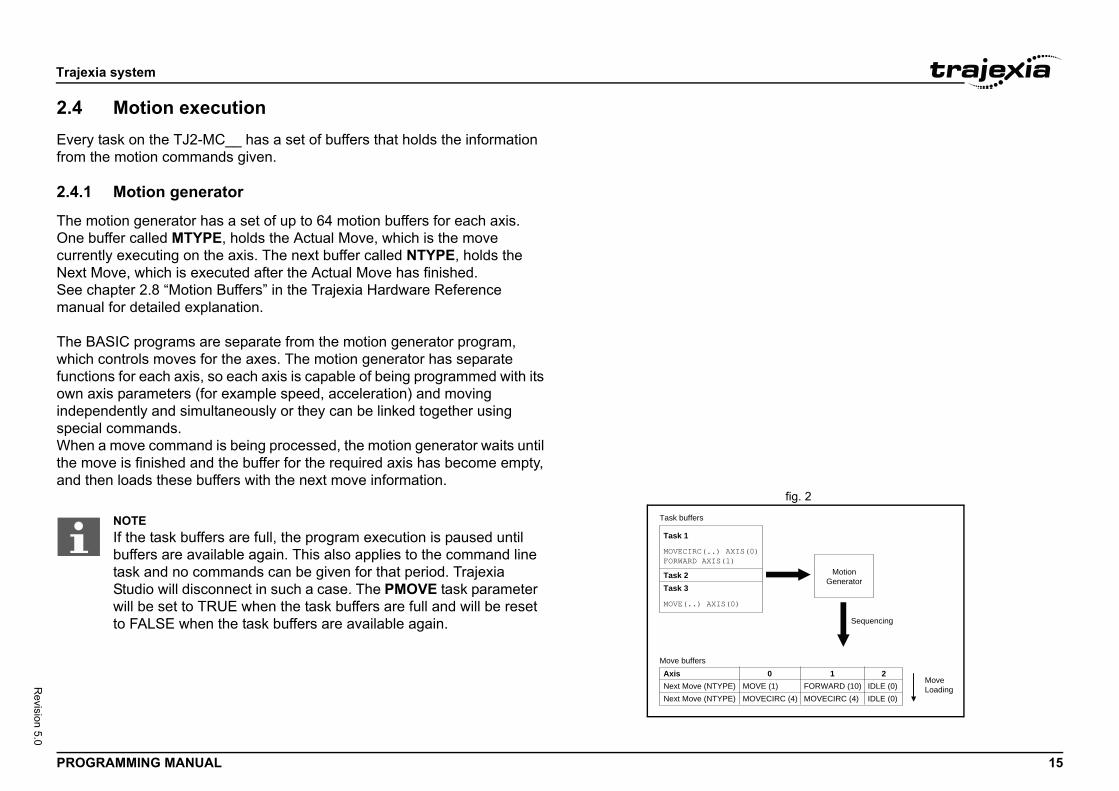
otion generator has a set of up to 64 motion buffers for each axis. uffer called MTYPE, holds the Actual Move, which is the move
ntly executing on the axis. The next buffer called NTYPE, holds the Move, which is executed after the Actual Move has finished. hapter 2.8 “Motion Buffers” in the Trajexia Hardware Reference al for detailed explanation.
ASIC programs are separate from the motion generator program, controls moves for the axes. The motion generator has separate ons for each axis, so each axis is capable of being programmed with its xis parameters (for example speed, acceleration) and moving endently and simultaneously or they can be linked together using al commands. a move command is being processed, the motion generator waits until ove is finished and the buffer for the required axis has become empty, hen loads these buffers with the next move information.
Axis
Task 1
MOVECIRC(..) AXIS(0)FORWARD AXIS(1)
MOVE(..) AXIS(0)
Task 2Task 3
Next Move (NTYPE)
Move buffers
Task buffers
Next Move (NTYPE)MOMO
NOTEIf the task buffers are full, the program execution is paused until buffers are available again. This also applies to the command line task and no commands can be given for that period. Trajexia Studio will disconnect in such a case. The PMOVE task parameter will be set to TRUE when the task buffers are full and will be reset to FALSE when the task buffers are available again.
Trajex
PROG 16
Revision 5.0
2.4.2
On eaexamany ato be axes correseque
2.4.3
Oncesee ifavailabuffermoveprocemarke
2.5The cexecuUse tconneTrajeCurso
2.6The Tcapachandlfiling The Tand frcontro
ms
package is used to store and load programs to iving, printing and editing. It also has several ing facilities. For more information please refer
anual.
re stored automatically in Flash-ROM memory he battery.
n
r the different tasks and the refreshing of the around the servo cycle period of the system.
ermined by the SERVO_PERIOD system ill either have a servo cycle period of 0.25, 0.5,
__ is refreshed at the beginning of every cycle
e digital inputs is transferred to the IN system his is the status captured in the previous servo
the speed references are updated.dated conform the status of the OP system
puts is captured.
ssing of the I/O signals is taking place, except hat all actions must be programmed in the
ia system
RAMMING MANUAL
Sequencing
ch servo cycle interrupt (see section 2.6.2), the motion generator ines the NTYPE buffers to see if any of them are available. If there are vailable then it checks the task buffers to see if there is a move waiting loaded. If a move can be loaded, then the data for all the specified is loaded from the task buffers into the NTYPE buffers and the sponding task buffers are marked as idle. This process is called ncing.
Move loading
sequencing has been completed, the MTYPE buffers are checked to any moves can be loaded. If the required MTYPE buffers are ble, then the move is loaded from the NTYPE buffers to the MTYPE s and the NTYPE buffers are marked as idle. This process is called loading. If there is a valid move in the MTYPE buffers, then it is ssed. When the move has been completed, the MTYPE buffers are d as idle.
Command line interfaceommand line interface provides a direct interface for the user to te commands and access parameters on the system.
he Terminal Window in Trajexia Studio when the TJ2-MC__ is cted.
xia Studio buffers the last used commands. Pressing the Up and Down r Key will cycle through the buffer to execute the command again.
BASIC programsJ2-MC__ can store up to 32 programs in memory, provided the ity of memory is not exceeded. The TJ2-MC__ supports simple file-ing instructions for managing these program files rather like the DOS system on a computer.rajexia Studio software package is used to store and load programs to om a computer for archiving, printing and editing. It also has several ller monitor and debugging facilities.
2.6.1 Managing progra
The Trajexia Studio softwareand from a computer for archcontroller monitor and debuggto the Trajexia Studio user m
Storing programsPrograms in the TJ2-MC__ aand therefore do not rely on t
2.6.2 Program executio
The timing of the execution foI/O of the TJ2-MC__ revolvesThe servo cycle period is detparameter. The TJ2-MC__ w1.0 or 2.0 ms.
I/O refreshThe I/O status of the TJ2-MCtime.• The captured status of th
input variable. Note that tcycle.
• The analogue outputs for• The digital outputs are up
output variable.• The status of the digital in
Note that no automatic procefor registration. This implies tBASIC programs.
Trajex
PROG 17
Revision 5.0
ReleTrajethe pThe fexecu/i
The uis expalloca
SettiProgrturneinterfaProgrsettinIf youPrioriRun avaluecurreFor mto sec
Comm
RUN
STOP
HALT
PROC
ia system
RAMMING MANUAL
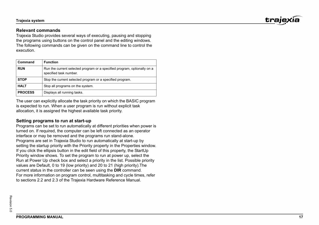
vant commandsxia Studio provides several ways of executing, pausing and stopping rograms using buttons on the control panel and the editing windows. ollowing commands can be given on the command line to control the tion.
ser can explicitly allocate the task priority on which the BASIC program ected to run. When a user program is run without explicit task tion, it is assigned the highest available task priority.
ng programs to run at start-upams can be set to run automatically at different priorities when power isd on. If required, the computer can be left connected as an operatorce or may be removed and the programs run stand-alone.
ams are set in Trajexia Studio to run automatically at start-up byg the startup priority with the Priority property in the Properties window. click the ellipsis button in the edit field of this property, the StartUpty window shows. To set the program to run at power up, select thet Power Up check box and select a priority in the list. Possible prioritys are Default, 0 to 19 (low priority) and 20 to 21 (high priority).The nt status in the controller can be seen using the DIR command.ore information on program control, multitasking and cycle times, refer tions 2.2 and 2.3 of the Trajexia Hardware Reference Manual.
and Function
Run the current selected program or a specified program, optionally on a specified task number.
Stop the current selected program or a specified program.
Stop all programs on the system.
ESS Displays all running tasks.

BASIC
PROG 18
Revision 5.0
3
3.1This sare:• A• A• C• C• I/• M• P• P• S• S• S• Ta
The licomm
3.1.1/i
Name
ACC
ADD_
ADDA
BACK
BASE
xis according to values of a movement profile stored in variable array.
xis according to values of a movement profile stored in variable array. The motion is linked to the measured nother axis to form a continuously variable software gear-
move on an axis.
he demand position of an axis to the measured move- other axis to produce an electronic gearbox.
ne of 7 origin search sequences to position an axis to an sition or reset a motion error.
current position as a new absolute position.
s together for error disabling.
e current alarm.
alarm status of the Servo Drive.
specified parameter of the Servo Drive.
Servo Drive.
ecific value to the specified parameter of the Servo Drive.
rameter of the EnDat absolute encoder.
parameter of the EnDat absolute encoder.
therCAT network and performs various operations on laves connected to the bus.
xis continuously forward at the speed set in the SPEED
ECHATROLINK-II network and performs various opera-CHATROLINK-II stations connected to the bus.
3 orthogonal axes in a helical move.
ed version of the MHELICAL command.
n
commands
RAMMING MANUAL
BASIC commands
Categoriesection lists all BASIC commands divided by categories. The categories
xis commands.xis parameters.ommunication commands and parameters.onstants.O commands, functions and parameters.athematical functions and operations.rogram commands.rogram control commands.lot parameters and modifiers.ystem commands and functions.ystem parameters.sk commands and parameters.
sts are quick reference guides only. A complete description of the ands is given in alphabetical order in the next section.
Axis commands
Description
Changes the ACCEL and DECEL at the same time.
DAC Sum to the DAC value of one axis to the analogue output of the base axis.
X Sets a link to a superimposed axis. All demand position movements for the superimposed axis will be added to any moves that are cur-rently being executed.
LASH Allows the backlash compensation to be loaded.
Used to set the base axis to which the commands and parameters are applied.
CAM Moves an athe TABLE
CAMBOX Moves an athe TABLEmotion of abox.
CANCEL Cancels the
CONNECT Connects tments of an
DATUM Performs oabsolute po
DEFPOS Defines the
DISABLE_GROUP Groups axe
DRIVE_ALARM Monitors th
DRIVE_CLEAR Clears the
Reads the
DRIVE_RESET Resets the
DRIVE_WRITE Writes a sp
ENCODER_READ Reads a pa
ENCODER_WRITE Writes to a
ETHERCAT Initializes EEtherCAT s
FORWARD Moves an aparameter.
MECHATROLINK Initializes Mtions on ME
MHELICAL Interpolates
MHELICALSP Forced spe
Name Descriptio
BASIC
PROG 19
Revision 5.0
MOV
MOV
MOV
MOV
MOV
MOV
MOV
MOV
MOV
MSPH
MSPH
R_RE
RAPI
REGI
REVE
SPHE
STEP
SYNC
VOLU
Name
tion
s the axis acceleration rate.
s the number of the axis to which the base axis is cur-ked to by ADDAX.
s the axis type.
information that are represented by the LEDs on the ver of the TJ1-FL02.
s the axis demand position at output of FRAME transfor-
and disables particular axis independently of other axis.
e absolute position of the forward travel limit in user NITS.
e absolute position of the reverse travel limit in user NITS.
rsion factor to scale the edges/ stepper pulses to a moreent scale. AXIS_UNITS is only used when a FRAME is
s the axis status.
the amount of backlash compensation.
the change in direction in radians of the last pro-d MOVESP/MOVEABSSP/MOVECIRCSP move of 2 or es.
the end of the window in which a registration mark is d.
the change in connection ratio when using the CT command.
BASIC program to interact with the move loading pro-facilitate knife rotation at sharp corners.
s the creep speed.
commands
RAMMING MANUAL
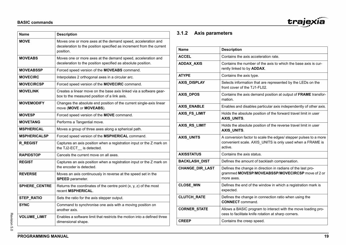
3.1.2 Axis parameters /iE Moves one or more axes at the demand speed, acceleration and
deceleration to the position specified as increment from the current position.
EABS Moves one or more axes at the demand speed, acceleration and deceleration to the position specified as absolute position.
EABSSP Forced speed version of the MOVEABS command.
ECIRC Interpolates 2 orthogonal axes in a circular arc.
ECIRCSP Forced speed version of the MOVECIRC command.
ELINK Creates a linear move on the base axis linked via a software gear-box to the measured position of a link axis.
EMODIFY Changes the absolute end position of the current single-axis linear move (MOVE or MOVEABS).
ESP Forced speed version of the MOVE command.
ETANG Performs a Tangential move.
ERICAL Moves a group of three axes along a spherical path.
ERICALSP Forced speed version of the MSPHERICAL command.
GIST Captures an axis position when a registration input or the Z mark on the TJ2-ECT__ is detected.
DSTOP Cancels the current move on all axes.
ST Captures an axis position when a registration input or the Z mark on the encoder is detected.
RSE Moves an axis continuously in reverse at the speed set in the SPEED parameter.
RE_CENTRE Returns the coordinates of the centre point (x, y, z) of the most recent MSPHERICAL.
_RATIO Sets the ratio for the axis stepper output.
Command to synchronise one axis with a moving position on another axis.
ME_LIMIT Enables a software limit that restricts the motion into a defined three dimensional shape.
Description
Name Descrip
ACCEL Contain
ADDAX_AXIS Containrently lin
ATYPE Contain
AXIS_DISPLAY Selectsfront co
AXIS_DPOS Containmation.
AXIS_ENABLE Enables
AXIS_FS_LIMIT Holds thAXIS_U
AXIS_RS_LIMIT Holds thAXIS_U
AXIS_UNITS A conveconveniactive.
AXISSTATUS Contain
BACKLASH_DIST Defines
CHANGE_DIR_LAST Definesgrammemore ax
CLOSE_WIN Definesexpecte
CLUTCH_RATE DefinesCONNE
CORNER_STATE Allows acess to
CREEP Contain
BASIC
PROG 20
Revision 5.0
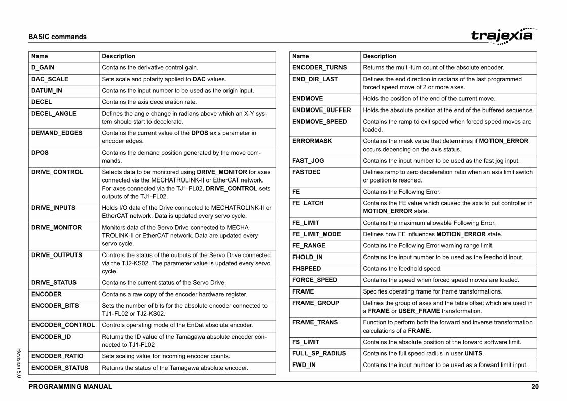
D_GA
DAC_
DATU
DECE
DECE
DEMA
DPOS
DRIV
DRIV
DRIV
DRIV
DRIV
ENCO
ENCO
ENCO
ENCO
ENCO
ENCO
Name
the multi-turn count of the absolute encoder.
the end direction in radians of the last programmed peed move of 2 or more axes.
e position of the end of the current move.
e absolute position at the end of the buffered sequence.
s the ramp to exit speed when forced speed moves are
s the mask value that determines if MOTION_ERROR epending on the axis status.
s the input number to be used as the fast jog input.
ramp to zero deceleration ratio when an axis limit switch ion is reached.
s the Following Error.
s the FE value which caused the axis to put controller in N_ERROR state.
s the maximum allowable Following Error.
how FE influences MOTION_ERROR state.
s the Following Error warning range limit.
s the input number to be used as the feedhold input.
s the feedhold speed.
s the speed when forced speed moves are loaded.
s operating frame for frame transformations.
the group of axes and the table offset which are used in E or USER_FRAME transformation.
n to perform both the forward and inverse transformation ions of a FRAME.
s the absolute position of the forward software limit.
s the full speed radius in user UNITS.
s the input number to be used as a forward limit input.
tion
commands
RAMMING MANUAL
IN Contains the derivative control gain.
SCALE Sets scale and polarity applied to DAC values.
M_IN Contains the input number to be used as the origin input.
L Contains the axis deceleration rate.
L_ANGLE Defines the angle change in radians above which an X-Y sys-tem should start to decelerate.
ND_EDGES Contains the current value of the DPOS axis parameter in encoder edges.
Contains the demand position generated by the move com-mands.
E_CONTROL Selects data to be monitored using DRIVE_MONITOR for axes connected via the MECHATROLINK-II or EtherCAT network. For axes connected via the TJ1-FL02, DRIVE_CONTROL sets outputs of the TJ1-FL02.
E_INPUTS Holds I/O data of the Drive connected to MECHATROLINK-II or EtherCAT network. Data is updated every servo cycle.
E_MONITOR Monitors data of the Servo Drive connected to MECHA-TROLINK-II or EtherCAT network. Data are updated every servo cycle.
E_OUTPUTS Controls the status of the outputs of the Servo Drive connected via the TJ2-KS02. The parameter value is updated every servo cycle.
E_STATUS Contains the current status of the Servo Drive.
DER Contains a raw copy of the encoder hardware register.
DER_BITS Sets the number of bits for the absolute encoder connected to TJ1-FL02 or TJ2-KS02.
DER_CONTROL Controls operating mode of the EnDat absolute encoder.
DER_ID Returns the ID value of the Tamagawa absolute encoder con-nected to TJ1-FL02
DER_RATIO Sets scaling value for incoming encoder counts.
DER_STATUS Returns the status of the Tamagawa absolute encoder.
Description
ENCODER_TURNS Returns
END_DIR_LAST Definesforced s
ENDMOVE Holds th
ENDMOVE_BUFFER Holds th
ENDMOVE_SPEED Containloaded.
ERRORMASK Containoccurs d
FAST_JOG Contain
FASTDEC Definesor posit
FE Contain
FE_LATCH ContainMOTIO
FE_LIMIT Contain
FE_LIMIT_MODE Defines
FE_RANGE Contain
FHOLD_IN Contain
FHSPEED Contain
FORCE_SPEED Contain
FRAME Specifie
FRAME_GROUP Definesa FRAM
FRAME_TRANS Functiocalculat
FS_LIMIT Contain
FULL_SP_RADIUS Contain
FWD_IN Contain
Name Descrip
BASIC
PROG 21
Revision 5.0
FWD
I_GA
INPU
INVE
JOGS
LIMIT
MAR
MARK
MERG
MOV
MPOS
MSPE
MTYP
NTYP
OFFP
OPEN
OUTL
OV_G
P_GA
R_MA
R_RE
Name
s the position at which the registration event on the an a TJ2-ECT__ occurred.
the angle change in radians above which an X-Y sys- interact with a BASIC program.
s the position at which the (primary) registration event d.
s the position at which the secondary registration event d.
s the speed when the (primary) registration event d.
s the speed when the secondary registration event d.
istance remaining to the end of the current move.
s or sets the repeat distance.
the application of the REP_DIST axis parameter.
s the input number to be used as a reverse limit input.
s the input number to be used as a jog reverse input.
s the absolute position of the reverse software limit.
s the speed reference value which is applied when the n open loop.
s the speed reference value being applied to the Servo r both open as closed loop.
ines whether the axis runs under servo control or open
s the demand speed in units/s.
res the voltage range of the analog speed reference out-e TJ1-FL02.
s the S-curve factor.
the start direction in radians of the last programmed peed move of 2 or more axes.
tion
commands
RAMMING MANUAL
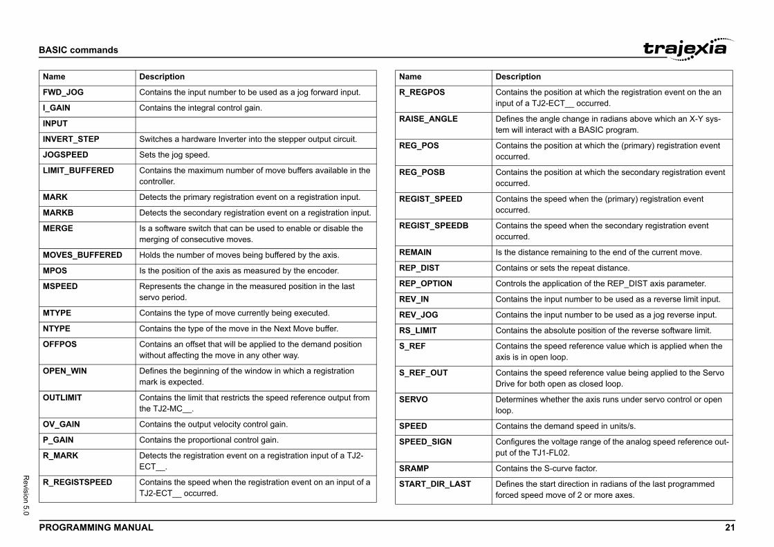
_JOG Contains the input number to be used as a jog forward input.
IN Contains the integral control gain.
T
RT_STEP Switches a hardware Inverter into the stepper output circuit.
PEED Sets the jog speed.
_BUFFERED Contains the maximum number of move buffers available in the controller.
K Detects the primary registration event on a registration input.
B Detects the secondary registration event on a registration input.
E Is a software switch that can be used to enable or disable the merging of consecutive moves.
ES_BUFFERED Holds the number of moves being buffered by the axis.
Is the position of the axis as measured by the encoder.
ED Represents the change in the measured position in the last servo period.
E Contains the type of move currently being executed.
E Contains the type of the move in the Next Move buffer.
OS Contains an offset that will be applied to the demand position without affecting the move in any other way.
_WIN Defines the beginning of the window in which a registration mark is expected.
IMIT Contains the limit that restricts the speed reference output from the TJ2-MC__.
AIN Contains the output velocity control gain.
IN Contains the proportional control gain.
RK Detects the registration event on a registration input of a TJ2-ECT__.
GISTSPEED Contains the speed when the registration event on an input of a TJ2-ECT__ occurred.
Description
R_REGPOS Containinput of
RAISE_ANGLE Definestem will
REG_POS Containoccurre
REG_POSB Containoccurre
REGIST_SPEED Containoccurre
REGIST_SPEEDB Containoccurre
REMAIN Is the d
REP_DIST Contain
REP_OPTION Controls
REV_IN Contain
REV_JOG Contain
RS_LIMIT Contain
S_REF Containaxis is i
S_REF_OUT ContainDrive fo
SERVO Determloop.
SPEED Contain
SPEED_SIGN Configuput of th
SRAMP Contain
START_DIR_LAST Definesforced s
Name Descrip
BASIC
PROG 22
Revision 5.0
ommands and parameters STOP
SYNC
SYNC
TOOL
T_RE
TABL
TANG
TRAN
UNIT
VECT
USER
USER
VFF_
Name
tion
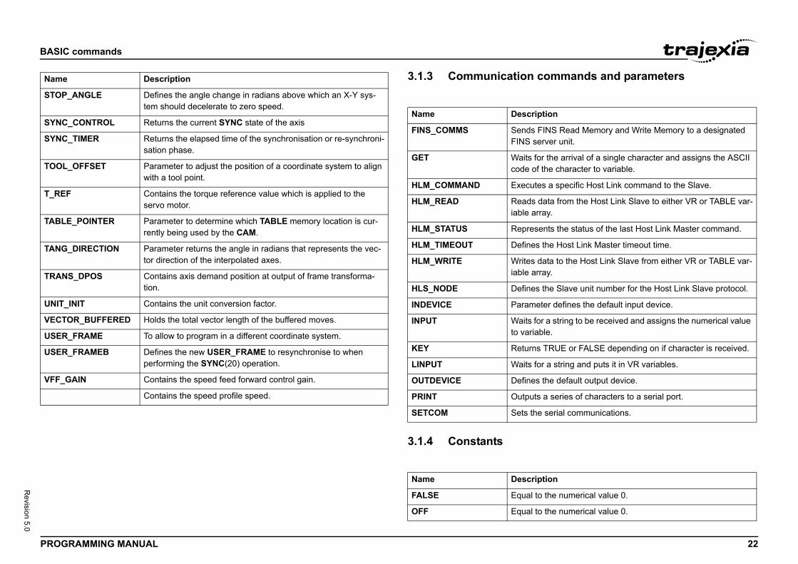
INS Read Memory and Write Memory to a designated rver unit.
r the arrival of a single character and assigns the ASCII the character to variable.
s a specific Host Link command to the Slave.
ata from the Host Link Slave to either VR or TABLE var-ray.
nts the status of the last Host Link Master command.
the Host Link Master timeout time.
ata to the Host Link Slave from either VR or TABLE var-ray.
the Slave unit number for the Host Link Slave protocol.
ter defines the default input device.
r a string to be received and assigns the numerical value ble.
TRUE or FALSE depending on if character is received.
r a string and puts it in VR variables.
the default output device.
a series of characters to a serial port.
serial communications.
tion
the numerical value 0.
the numerical value 0.
commands
RAMMING MANUAL
3.1.3 Communication c/i
3.1.4 Constants/i
_ANGLE Defines the angle change in radians above which an X-Y sys-tem should decelerate to zero speed.
_CONTROL Returns the current SYNC state of the axis
_TIMER Returns the elapsed time of the synchronisation or re-synchroni-sation phase.
_OFFSET Parameter to adjust the position of a coordinate system to align with a tool point.
F Contains the torque reference value which is applied to the servo motor.
E_POINTER Parameter to determine which TABLE memory location is cur-rently being used by the CAM.
_DIRECTION Parameter returns the angle in radians that represents the vec-tor direction of the interpolated axes.
S_DPOS Contains axis demand position at output of frame transforma-tion.
_INIT Contains the unit conversion factor.
OR_BUFFERED Holds the total vector length of the buffered moves.
_FRAME To allow to program in a different coordinate system.
_FRAMEB Defines the new USER_FRAME to resynchronise to whenperforming the SYNC(20) operation.
GAIN Contains the speed feed forward control gain.
Contains the speed profile speed.
Description
Name Descrip
FINS_COMMS Sends FFINS se
GET Waits focode of
HLM_COMMAND Execute
HLM_READ Reads diable ar
HLM_STATUS Represe
HLM_TIMEOUT Defines
HLM_WRITE Writes diable ar
HLS_NODE Defines
INDEVICE Parame
INPUT Waits foto varia
KEY Returns
LINPUT Waits fo
OUTDEVICE Defines
PRINT Outputs
SETCOM Sets the
Name Descrip
FALSE Equal to
OFF Equal to
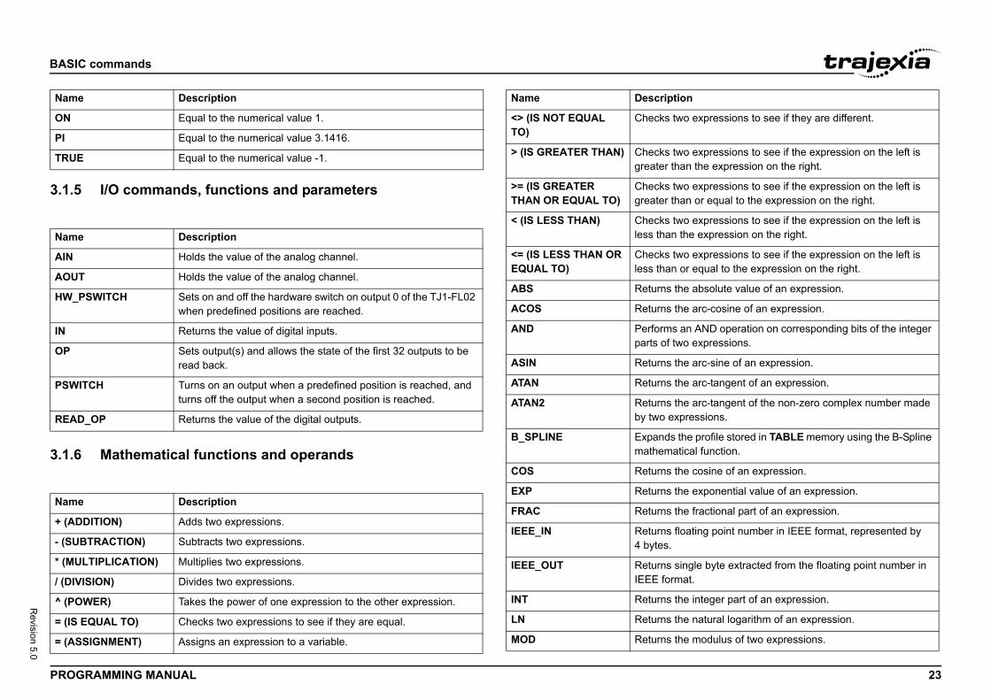
BASIC
PROG 23
Revision 5.0
3.1.5/i
3.1.6/i
ON
PI
TRUE
Name
AIN
AOUT
HW_P
IN
OP
PSW
READ
Name
+ (AD
- (SU
* (MU
/ (DIV
^ (PO
= (IS
= (AS
Name
two expressions to see if they are different.
two expressions to see if the expression on the left is than the expression on the right.
two expressions to see if the expression on the left is than or equal to the expression on the right.
two expressions to see if the expression on the left is n the expression on the right.
two expressions to see if the expression on the left is n or equal to the expression on the right.
the absolute value of an expression.
the arc-cosine of an expression.
s an AND operation on corresponding bits of the integer two expressions.
the arc-sine of an expression.
the arc-tangent of an expression.
the arc-tangent of the non-zero complex number made xpressions.
s the profile stored in TABLE memory using the B-Spline atical function.
the cosine of an expression.
the exponential value of an expression.
the fractional part of an expression.
floating point number in IEEE format, represented by
single byte extracted from the floating point number in rmat.
the integer part of an expression.
the natural logarithm of an expression.
the modulus of two expressions.
tion
commands
RAMMING MANUAL
I/O commands, functions and parameters
Mathematical functions and operands
Equal to the numerical value 1.
Equal to the numerical value 3.1416.
Equal to the numerical value -1.
Description
Holds the value of the analog channel.
Holds the value of the analog channel.
SWITCH Sets on and off the hardware switch on output 0 of the TJ1-FL02 when predefined positions are reached.
Returns the value of digital inputs.
Sets output(s) and allows the state of the first 32 outputs to be read back.
ITCH Turns on an output when a predefined position is reached, and turns off the output when a second position is reached.
_OP Returns the value of the digital outputs.
Description
DITION) Adds two expressions.
BTRACTION) Subtracts two expressions.
LTIPLICATION) Multiplies two expressions.
ISION) Divides two expressions.
WER) Takes the power of one expression to the other expression.
EQUAL TO) Checks two expressions to see if they are equal.
SIGNMENT) Assigns an expression to a variable.
Description
<> (IS NOT EQUAL TO)
Checks
> (IS GREATER THAN) Checksgreater
>= (IS GREATER THAN OR EQUAL TO)
Checksgreater
< (IS LESS THAN) Checksless tha
<= (IS LESS THAN OR EQUAL TO)
Checksless tha
ABS Returns
ACOS Returns
AND Performparts of
ASIN Returns
ATAN Returns
ATAN2 Returnsby two e
B_SPLINE Expandmathem
COS Returns
EXP Returns
FRAC Returns
IEEE_IN Returns4 bytes.
IEEE_OUT ReturnsIEEE fo
INT Returns
LN Returns
MOD Returns
Name Descrip
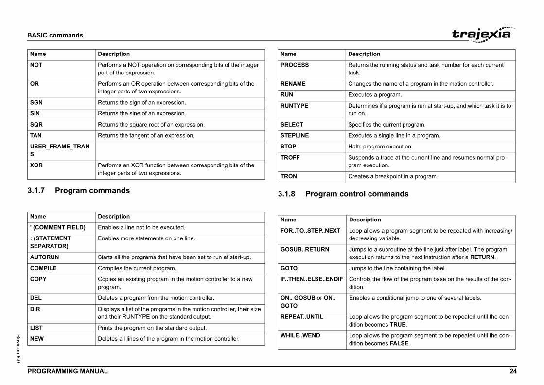
BASIC
PROG 24
Revision 5.0
3.1.7/i
commands
NOT
OR
SGN
SIN
SQR
TAN
USERS
XOR
Name
' (CO
: (STASEPA
AUTO
COM
COPY
DEL
DIR
LIST
NEW
Name
the running status and task number for each current
s the name of a program in the motion controller.
s a program.
ines if a program is run at start-up, and which task it is to
s the current program.
s a single line in a program.
ogram execution.
ds a trace at the current line and resumes normal pro-ecution.
a breakpoint in a program.
tion
lows a program segment to be repeated with increasing/ing variable.
to a subroutine at the line just after label. The program on returns to the next instruction after a RETURN.
to the line containing the label.
s the flow of the program base on the results of the con-
a conditional jump to one of several labels.
lows the program segment to be repeated until the con-ecomes TRUE.
lows the program segment to be repeated until the con-ecomes FALSE.
tion
commands
RAMMING MANUAL
Program commands 3.1.8 Program control /i
Performs a NOT operation on corresponding bits of the integer part of the expression.
Performs an OR operation between corresponding bits of the integer parts of two expressions.
Returns the sign of an expression.
Returns the sine of an expression.
Returns the square root of an expression.
Returns the tangent of an expression.
_FRAME_TRAN
Performs an XOR function between corresponding bits of the integer parts of two expressions.
Description
MMENT FIELD) Enables a line not to be executed.
TEMENT RATOR)
Enables more statements on one line.
RUN Starts all the programs that have been set to run at start-up.
PILE Compiles the current program.
Copies an existing program in the motion controller to a new program.
Deletes a program from the motion controller.
Displays a list of the programs in the motion controller, their size and their RUNTYPE on the standard output.
Prints the program on the standard output.
Deletes all lines of the program in the motion controller.
Description
PROCESS Returnstask.
RENAME Change
RUN Execute
RUNTYPE Determrun on.
SELECT Specifie
STEPLINE Execute
STOP Halts pr
TROFF Suspengram ex
TRON Creates
Name Descrip
FOR..TO..STEP..NEXT Loop aldecreas
GOSUB..RETURN Jumps executi
GOTO Jumps
IF..THEN..ELSE..ENDIF Controldition.
ON.. GOSUB or ON.. GOTO
Enables
REPEAT..UNTIL Loop aldition b
WHILE..WEND Loop aldition b
Name Descrip
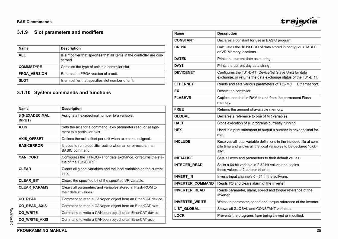
BASIC
PROG 25
Revision 5.0
3.1.9/i
3.1.1/i
Name
ALL
COM
FPGA
SLOT
Name
$ (HEINPU
AXIS
AXIS
BASI
CAN_
CLEA
CLEA
CLEA
CO_R
CO_R
CO_W
CO_W
s a constant for use in BASIC program.
tes the 16 bit CRC of data stored in contiguous TABLE emory locations.
he current date as a string.
he current day as a string
res the TJ1-DRT (DeviceNet Slave Unit) for data ge, or returns the data exchange status of the TJ1-DRT.
and sets various parameters of TJ2-MC__ Ethernet port.
the controller.
user data in RAM to and from the permanent Flash y.
the amount of available memory.
s a reference to one of VR variables.
xecution of all programs currently running.
a print statement to output a number in hexadecimal for-
es all local variable definitions in the included file at com-e and allows all the local variables to be declared “glob-
l axes and parameters to their default values.
64 bit variable in 2 32 bit values and copiesalues to 2 other variables.
input channels 0 - 31 in the software.
I/O and clears alarm of the Inverter.
parameter, alarm, speed and torque reference of the r.
to parameter, speed and torque reference of the Inverter.
all GLOBAL and CONSTANT variables.
ts the programs from being viewed or modified.
ption
commands
RAMMING MANUAL
Slot parameters and modifiers
0 System commands and functions
Description
Is a modifier that specifies that all items in the controller are con-cerned.
MSTYPE Contains the type of unit in a controller slot.
_VERSION Returns the FPGA version of a unit.
Is a modifier that specifies slot number of unit.
Description
XADECIMAL T)
Assigns a hexadecimal number to a variable.
Sets the axis for a command, axis parameter read, or assign-ment to a particular axis.
_OFFSET Defines the axis offset per unit when axes are assigned.
CERROR Is used to run a specific routine when an error occurs in a BASIC command.
CORT Configures the TJ1-CORT for data exchange, or returns the sta-tus of the TJ1-CORT.
R Clears all global variables and the local variables on the current task.
R_BIT Clears the specified bit of the specified VR variable.
R_PARAMS Clears all parameters and variables stored in Flash-ROM to their default values.
EAD Command to read a CANopen object from an EtherCAT device.
EAD_AXIS Command to read a CANopen object from an EtherCAT axis.
RITE Command to write a CANopen object of an EtherCAT device.
RITE_AXIS Command to write a CANopen object of an EtherCAT axis.
CONSTANT Declare
CRC16 Calculaor VR M
DATE$ Prints t
DAY$ Prints t
DEVICENET Configuexchan
ETHERNET Reads
EX Resets
FLASHVR Copiesmemor
FREE Returns
GLOBAL Declare
HALT Stops e
HEX Used inmat.
INCLUDE Resolvpile timally”.
INITIALISE Sets al
INTEGER_READ Splits athese v
INVERT_IN Inverts
INVERTER_COMMAND Reads
INVERTER_READ Reads Inverte
INVERTER_WRITE Writes
LIST_GLOBAL Shows
LOCK Preven
Name Descri
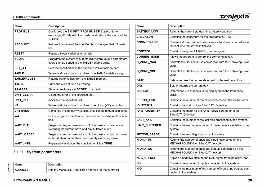
BASIC
PROG 26
Revision 5.0
3.1.1/i
PROF
READ
RESE
SCOP
SET_
TABL
TABL
TIME
TRIG
UNIT
UNIT
VR
VRST
WA
WAIT
WAIT
WAIT
Name
ADDR
Name
the current status of the battery condition.
s the checksum for the programs in RAM.
s all the communications errors that have occurred since time that it was initialised.
s the type of TJ2-MC__ in the system.
he program to control the cornering action.
the DAC output in conjunction with the Following Error
the DAC output in conjunction with the Following Error
returns the current date held by the real time clock.
returns the current day.
ines I/O channels to be displayed on the front panel
s the number of the axis which caused the motion error.
s the status of an EtherCAT IO device.
s the mask for the IO_STATUS parameter of an T IO device.
s the number of the last axis processed by the system.
s the maximum number of move buffers available in the
s an error flag for axis motion errors.
the number of analogue inputs connected on the TROLINK-II or EtherCAT network.
the number of analogue outputs connected on the TROLINK-II or EtherCAT network.
a negative offset to the DAC signal from the servo loop.
s the number of inputs connected to the system.
s the maximum of the number of inputs and outputs con-to the system.
tion
commands
RAMMING MANUAL
1 System parameters
IBUS Configures the TJ1-PRT (PROFIBUS-DP Slave Unit) to exchange I/O data with the master and returns the status of the TJ1-PRT.
_BIT Returns the value of the specified bit in the specified VR varia-ble.
T Resets all local variables on a task.
E Programs the system to automatically store up to 4 parameters every sample period to the TABLE variable array.
BIT Sets the specified bit in the specified VR variable to one.
E Writes and reads data to and from the TABLE variable array.
EVALUES Returns list of values from the TABLE memory.
$ Prints the current time as a string.
GER Starts a previously set SCOPE command.
_CLEAR Clears the error of the specified unit.
_INIT Initialises the specified unit.
Writes and reads data to and from the global (VR) variables.
RING Combines VR memory values so they can be printed as a string.
Holds program execution for the number of milliseconds speci-fied.
IDLE Suspends program execution until the base axis has finished executing its current move and any buffered move.
LOADED Suspends program execution until the base axis has no moves buffered ahead other than the currently executing move.
UNTIL Repeatedly evaluates the condition until it is TRUE.
Description
ESS Sets the ModbusRTU multidrop address for the controller
Description
BATTERY_LOW Returns
CHECKSUM Contain
COMMSERROR Containthe last
CONTROL Contain
CORNER_MODE Allows t
D_ZONE_MAX Controlsvalue.
D_ZONE_MIN Controlsvalue.
DATE Sets or
DAY Sets or
DISPLAY DetermLEDs.
ERROR_AXIS Contain
IO_STATUS Contain
IO_STATUSMASK ContainEtherCA
LAST_AXIS Contain
LIMIT_BUFFERED Containsystem.
MOTION_ERROR Contain
N_ANA_IN ReturnsMECHA
N_ANA_OUT ReturnsMECHA
NEG_OFFSET Applies
NIN Contain
NIO Containnected
Name Descrip
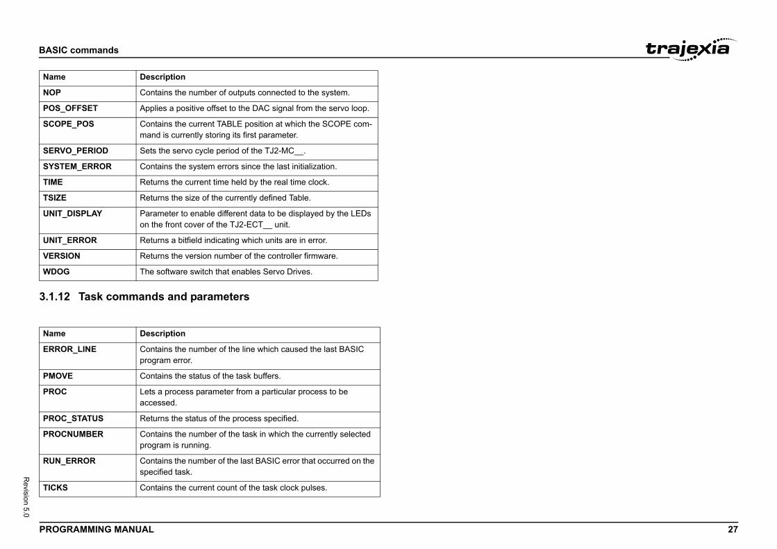
BASIC
PROG 27
Revision 5.0
3.1.1/i
NOP
POS_
SCOP
SERV
SYST
TIME
TSIZE
UNIT
UNIT
VERS
WDO
Name
ERRO
PMO
PROC
PROC
PROC
RUN_
TICK
Name
commands
RAMMING MANUAL
2 Task commands and parameters
Contains the number of outputs connected to the system.
OFFSET Applies a positive offset to the DAC signal from the servo loop.
E_POS Contains the current TABLE position at which the SCOPE com-mand is currently storing its first parameter.
O_PERIOD Sets the servo cycle period of the TJ2-MC__.
EM_ERROR Contains the system errors since the last initialization.
Returns the current time held by the real time clock.
Returns the size of the currently defined Table.
_DISPLAY Parameter to enable different data to be displayed by the LEDs on the front cover of the TJ2-ECT__ unit.
_ERROR Returns a bitfield indicating which units are in error.
ION Returns the version number of the controller firmware.
G The software switch that enables Servo Drives.
Description
R_LINE Contains the number of the line which caused the last BASIC program error.
VE Contains the status of the task buffers.
Lets a process parameter from a particular process to be accessed.
_STATUS Returns the status of the process specified.
NUMBER Contains the number of the task in which the currently selected program is running.
ERROR Contains the number of the last BASIC error that occurred on the specified task.
S Contains the current count of the task clock pulses.
Description
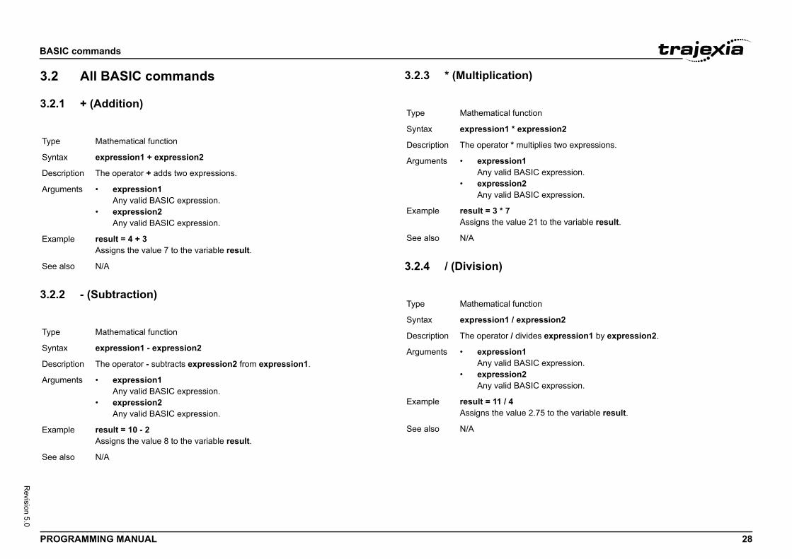
BASIC
PROG 28
Revision 5.0
3.2
3.2.1/i
3.2.2/i
Type
Synta
Descr
Argum
Exam
See a
Type
Synta
Descr
Argum
Exam
See a
n
ession2
lies two expressions.
expression.
expression.
to the variable result.
n
ssion2
s expression1 by expression2.
expression.
expression.
75 to the variable result.
commands
RAMMING MANUAL
All BASIC commands
+ (Addition)
- (Subtraction)
3.2.3 * (Multiplication)/i
3.2.4 / (Division)/i
Mathematical function
x expression1 + expression2
iption The operator + adds two expressions.
ents • expression1Any valid BASIC expression.
• expression2Any valid BASIC expression.
ple result = 4 + 3Assigns the value 7 to the variable result.
lso N/A
Mathematical function
x expression1 - expression2
iption The operator - subtracts expression2 from expression1.
ents • expression1Any valid BASIC expression.
• expression2Any valid BASIC expression.
ple result = 10 - 2Assigns the value 8 to the variable result.
lso N/A
Type Mathematical functio
Syntax expression1 * expr
Description The operator * multip
Arguments • expression1Any valid BASIC
• expression2Any valid BASIC
Example result = 3 * 7Assigns the value 21
See also N/A
Type Mathematical functio
Syntax expression1 / expre
Description The operator / divide
Arguments • expression1Any valid BASIC
• expression2Any valid BASIC
Example result = 11 / 4Assigns the value 2.
See also N/A
BASIC
PROG 29
Revision 5.0
3.2.5/i
3.2.6/i
)
Type
Synta
Descr
Argum
Exam
See a
Type
Synta
Descr
Argum
Exam
See a
n
on
ns the value of the expression to the variable.
.
expression.
to the variable var.
n
ression2
rns TRUE if expression1 is not equal to expression2, ALSE.
expression.
expression.
TO label1 a value not equal to 10, program execution continues at ise, program execution continues with the next state-
commands
RAMMING MANUAL
^ (Power)
= (Is equal to)
3.2.7 = (Assignment)/i
3.2.8 <> (Is not equal to/i
Mathematical function
x expression1 ^ expression2
iption The power operator ^ raises expression1 to the power of expression2.This operation uses floating point algorithms and may give small deviations for integer calculations.
ents • expression1Any valid BASIC expression.
• expression2Any valid BASIC expression.
ple result = 2^5Assigns the value 32 to the variable result.
lso N/A
Mathematical function
x expression1 = expression2
iption The operator = returns TRUE if expression1 is equal to expression2, other-wise it returns FALSE.
ents • expression1Any valid BASIC expression.
• expression2Any valid BASIC expression.
ple IF a = 10 THEN GOTO label1If variable a contains a value equal to 10, program execution continues at label label1. Otherwise, program execution continues with the next statement.
lso N/A
Type Mathematical functio
Syntax variable = expressi
Description The operator = assig
Arguments • variableA variable name
• expressionAny valid BASIC
Example var = 18Assigns the value 18
See also N/A
Type Mathematical functio
Syntax expression1 <> exp
Description The operator <> retuotherwise it returns F
Arguments • expression1Any valid BASIC
• expression2Any valid BASIC
Example IF a <> 10 THEN GOIf variable a containslabel label1. Otherwment.
See also N/A
BASIC
PROG 30
Revision 5.0
3.2.9/i
3.2.1/i
r equal to)
Type
Synta
Descr
Argum
Exam
See a
Type
Synta
Descr
Argum
Exam
See a
n
ession2
ns TRUE if expression1 is less than ise it returns FALSE.
expression.
expression.
O label1 a value less than 10, program execution con-. Otherwise, program execution continues
ent.
n
ression2
rns TRUE if expression1 is less than or equal to ise it returns FALSE.
expression.
expression.
TO label1 a value less than or equal to 10, program execution con-. Otherwise, program execution continues with the next
commands
RAMMING MANUAL
> (Is greater than)
0 >= (Is greater than or equal to)
3.2.11 < (Is less than)/i
3.2.12 <= (Is less than o/i
Mathematical function
x expression1 > expression2
iption The operator > returns TRUE if expression1 is greater than expression2, otherwise it returns FALSE.
ents • expression1Any valid BASIC expression.
• expression2Any valid BASIC expression.
ple IF a > 10 THEN GOTO label1If variable a contains a value greater than 10, program execution continues at label label1. Otherwise, program execution continues with the next state-ment.
lso N/A
Mathematical function
x expression1 >= expression2
iption The operator >= returns TRUE if expression1 is greater than or equal to expression2, otherwise it returns FALSE.
ents • expression1Any valid BASIC expression.
• expression2Any valid BASIC expression.
ple IF a >=10 THEN GOTO label1If variable a contains a value greater than or equal to 10, program execution continues at label label1. Otherwise, program execution continues with the next statement.
lso N/A
Type Mathematical functio
Syntax expression1 < expr
Description The operator < returexpression2, otherw
Arguments • expression1Any valid BASIC
• expression2Any valid BASIC
Example IF a < 10 THEN GOTIf variable a containstinues at label label1with the next statem
See also N/A
Type Mathematical functio
Syntax expression1 <= exp
Description The operator <= retuexpression2, otherw
Arguments • expression1Any valid BASIC
• expression2Any valid BASIC
Example IF a <= 10 THEN GOIf variable a containstinues at label label1statement.
See also N/A
BASIC
PROG 31
Revision 5.0
3.2.1/i
3.2.1/i
rator)
Type
Synta
Descr
Argum
Exam
See a
Type
Synta
Descr
Argum
Exam
See a
ator : separates multiple BASIC statements on one line. command line and in programs.
: GET low : PRINT "DOES THREE THINGS"
d to specify a communications channel to be used for mmands.ns Channels greater than 3 will only be used when run-dio software.
T #1, kS232 port, which represent communication channel 1.
commands
RAMMING MANUAL
3 $ (Hexadecimal input)
4 ' (Comment field)
3.2.15 : (Statement sepa/i
3.2.16 #/i
System command
x $hex_num
iption The $ command makes the number that follows a hexadecimal number.
ents • hex_numA hexadecimal number (consisting of the characters 0 - 9 and A - F). hex_num ranges from 0 to 1FFFFFFFFFFFFF.
ple >>TABLE(0, $F, $ABCD)>>print TABLE(0), TABLE(1)15.0000 43981.0000
lso HEX (PRINT)
Program command
x '
iption ' marks all that follows it on a line as comment and not program code. Com-ment is not executed when the program is run. You can use ' at the beginning of a line or after a valid statement.
ents N/A
ple ' This line is not printedPRINT "Start"
lso N/A
Type Program command
Syntax :
Description The statement separYou can use it on the
Arguments N/A
Example PRINT "THIS LINE"
See also N/A
Type Special character
Syntax #
Description The # symbol is useserial input/output coNote: Communicationing the Trajexia Stu
Arguments N/A
Example PRINT #1, "RS232"PRINT #2, "RS485"
Example IF KEY #1 THEN GEChecks keypad on R
See also N/A
BASIC
PROG 32
Revision 5.0
3.2.1/i
3.2.1/i
Type
Synta
Descr
Argum
Exam
See a
Type
Synta
Descr
Argum
Exam
See a
n
rameter contains the axis acceleration rate. The rate is arameter can have any positive value including zero.
acceleration raten rate: "; ACCEL; " mm/s/s"00 ' Sets acceleration rate for axis (2)
IT_INIT
n
returns the arc-cosine of the expression. The expression en -1 and 1. The result in radians is between 0 and PI.
the range will return 0.
expression.
commands
RAMMING MANUAL
7 ABS
8 ACC
3.2.19 ACCEL/i
3.2.20 ACOS/i
Mathematical function
x ABS(expression)
iption The ABS function returns the absolute value of an expression.
ents • expressionAny valid BASIC expression.
ple IF ABS(A) > 100 THEN PRINT "A is outside range -100 ... 100"
lso N/A
Axis command
x ACC(rate)
iption Sets the acceleration and deceleration at the same time.This command gives a quick method to set both ACCEL and DECEL. Accel-eration and deceleration rates are recommended to be set with the ACCEL and DECEL axis parameters.
ents • rateThe acceleration/deceleration rate in units/s2. You can define the units with the UNITS axis parameter.
ple ACC(100)Sets ACCEL and DECEL to 100 units/s2.
lso ACCEL, DECEL, UNIT_INIT
Type Axis parameter
Syntax ACCEL = expressio
Description The ACCEL axis paset in units/s2. The p
Arguments N/A
Example BASE(0)ACCEL = 100 ' Set PRINT "AcceleratioACCEL AXIS(2) = 1
See also ACCEL, DECEL, UN
Type Mathematical functio
Syntax ACOS(expression)
Description The ACOS function value must be betweInput values outside
Arguments • expressionAny valid BASIC
Example >> PRINT ACOS(-1)3.1416
See also N/A
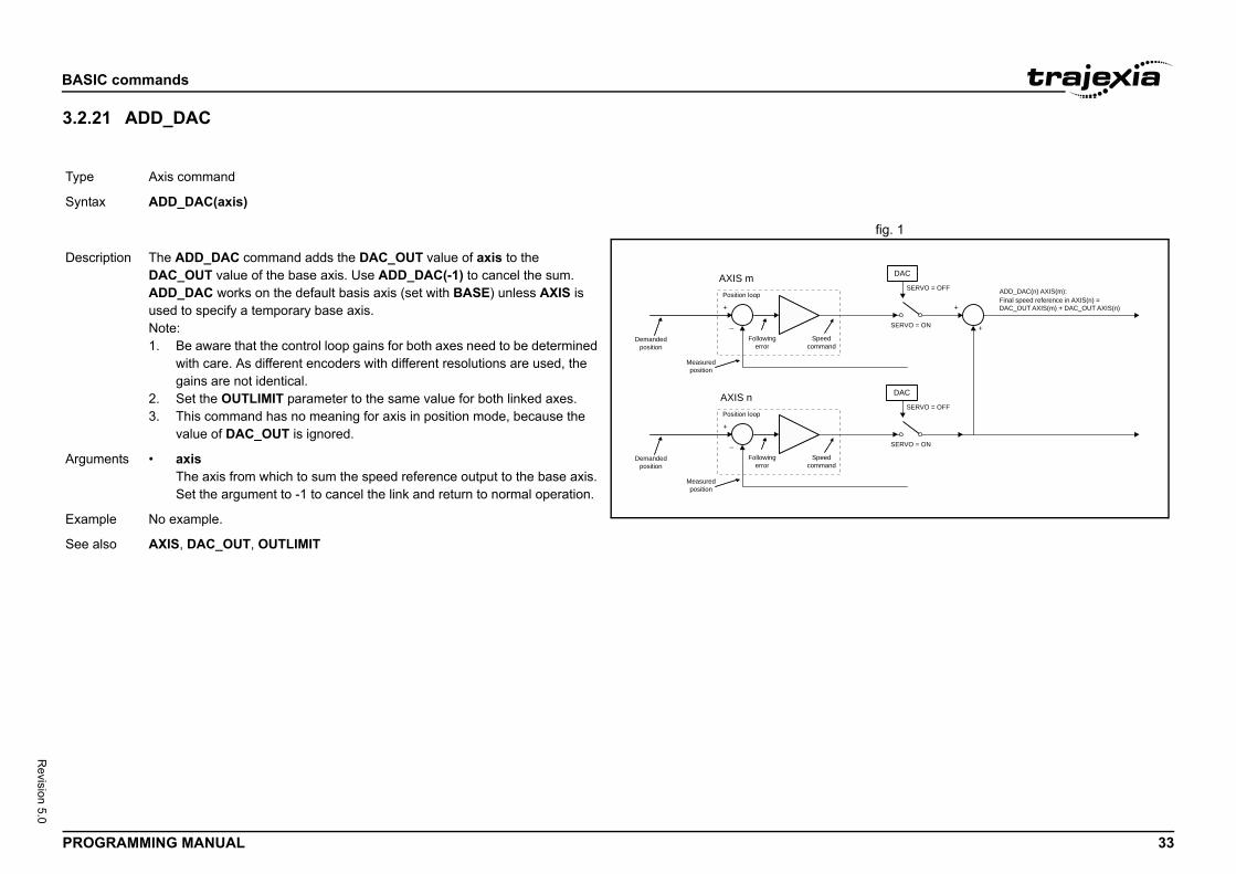
BASIC
PROG 33
Revision 5.0
3.2.2/i
fig. 1/i
Type
Synta
SERVO = OFF
SERVO = ON
Final speed reference in AXIS(n) =DAC_OUT AXIS(m) + DAC_OUT AXIS(n)
ADD_DAC(n) AXIS(m):
+
+
SERVO = OFF
SERVO = ON
DAC
DAC
Descr
Argum
Exam
See a
commands
RAMMING MANUAL
1 ADD_DAC
Axis command
x ADD_DAC(axis)
+
_
AXIS mPosition loop
+
_
AXIS nPosition loop
Speed command
Following error
Speed command
Following error
Demanded position
Demanded position
Measured position
Measured position
iption The ADD_DAC command adds the DAC_OUT value of axis to the DAC_OUT value of the base axis. Use ADD_DAC(-1) to cancel the sum.ADD_DAC works on the default basis axis (set with BASE) unless AXIS is used to specify a temporary base axis.Note:1. Be aware that the control loop gains for both axes need to be determined
with care. As different encoders with different resolutions are used, the gains are not identical.
2. Set the OUTLIMIT parameter to the same value for both linked axes.3. This command has no meaning for axis in position mode, because the
value of DAC_OUT is ignored.
ents • axisThe axis from which to sum the speed reference output to the base axis. Set the argument to -1 to cancel the link and return to normal operation.
ple No example.
lso AXIS, DAC_OUT, OUTLIMIT
BASIC
PROG 34
Revision 5.0
3.2.2/i
Type
Synta
Descr
Argum
commands
RAMMING MANUAL
2 ADDAX
Axis command
x ADDAX(axis)
iption The ADDAX command is used to superimpose two or more movements to build up a more complex movement profile.The ADDAX command takes the demand position changes from the superim-posed axis as specified by the axis argument and adds them to any move-ment running on the axis to which the command is issued. The axis specified by the parameter can be any axis and does not have to physically exist in the system.The ADDAX command therefore allows an axis to perform the moves speci-fied on two axes added together. When the axis parameter is set to OFF on an axis with an encoder interface the measured position MPOS is copied into the demanded position DPOS. This allows ADDAX to be used to sum encoder inputs.After the ADDAX command has been issued the link between the two axes remains until broken. Use ADDAX(-1) to cancel the axis link. ADDAX allows an axis to perform the moves specified for 2 axes added together. Combina-tions of more than two axes can be made by applying ADDAX to the superim-posed axis as well.ADDAX works on the default basis axis (set with BASE) unless AXIS is used to specify a temporary base axis.Note: The ADDAX command sums the movements in encoder edge units.
ents • axisThe axis to be set as a superimposed axis. Set the argument to -1 to can-cel the link and return to normal operation.
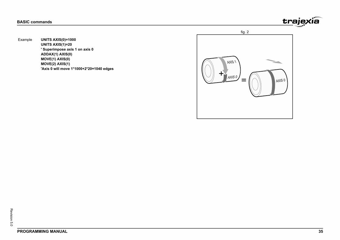
BASIC
PROG 35
Revision 5.0
fig. 2/i
Exam
commands
RAMMING MANUAL
ple UNITS AXIS(0)=1000UNITS AXIS(1)=20' Superimpose axis 1 on axis 0ADDAX(1) AXIS(0)MOVE(1) AXIS(0)MOVE(2) AXIS(1)'Axis 0 will move 1*1000+2*20=1040 edges
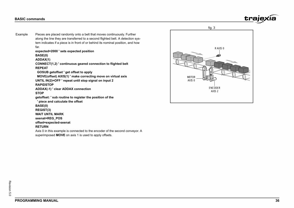
BASIC
PROG 36
Revision 5.0
fig. 3/i
ENCODERAXIS 2
R AXIS 0
Exam
commands
RAMMING MANUAL
MOTORAXIS 0
ple Pieces are placed randomly onto a belt that moves continuously. Further along the line they are transferred to a second flighted belt. A detection sys-tem indicates if a piece is in front of or behind its nominal position, and how far.expected=2000 ' sets expected positionBASE(0)ADDAX(1)CONNECT(1,2) ' continuous geared connection to flighted beltREPEAT GOSUB getoffset ' get offset to apply MOVE(offset) AXIS(1) ' make correcting move on virtual axisUNTIL IN(2)=OFF ' repeat until stop signal on input 2RAPIDSTOPADDAX(-1) ' clear ADDAX connectionSTOPgetoffset: ' sub routine to register the position of the ' piece and calculate the offsetBASE(0)REGIST(3)WAIT UNTIL MARKseenat=REG_POSoffset=expected-seenatRETURNAxis 0 in this example is connected to the encoder of the second conveyor. A superimposed MOVE on axis 1 is used to apply offsets.
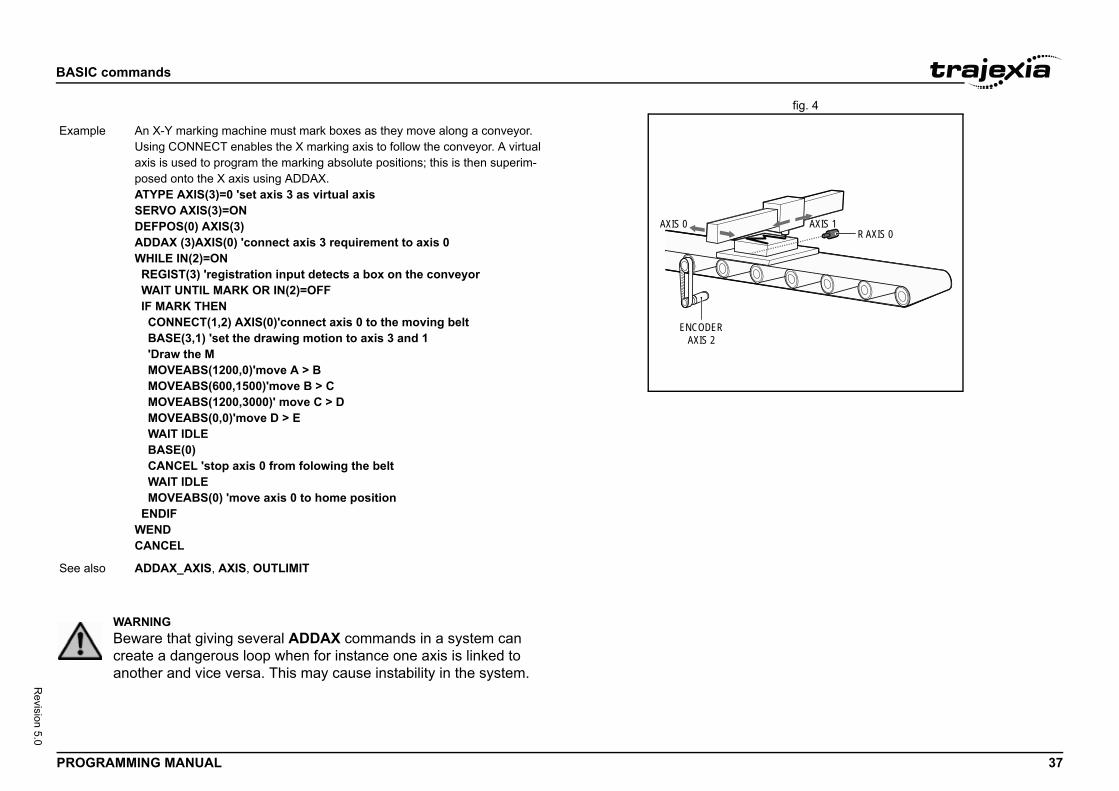
BASIC
PROG 37
Revision 5.0
fig. 4/i
R AXIS 0AXIS 1
Exam
See a
commands
RAMMING MANUAL
AXIS 0
ENCODERAXIS 2
ple An X-Y marking machine must mark boxes as they move along a conveyor. Using CONNECT enables the X marking axis to follow the conveyor. A virtual axis is used to program the marking absolute positions; this is then superim-posed onto the X axis using ADDAX.ATYPE AXIS(3)=0 'set axis 3 as virtual axisSERVO AXIS(3)=ONDEFPOS(0) AXIS(3)ADDAX (3)AXIS(0) 'connect axis 3 requirement to axis 0WHILE IN(2)=ON REGIST(3) 'registration input detects a box on the conveyor WAIT UNTIL MARK OR IN(2)=OFF IF MARK THEN CONNECT(1,2) AXIS(0)'connect axis 0 to the moving belt BASE(3,1) 'set the drawing motion to axis 3 and 1 'Draw the M MOVEABS(1200,0)'move A > B MOVEABS(600,1500)'move B > C MOVEABS(1200,3000)' move C > D MOVEABS(0,0)'move D > E WAIT IDLE BASE(0) CANCEL 'stop axis 0 from folowing the belt WAIT IDLE MOVEABS(0) 'move axis 0 to home position ENDIFWENDCANCEL
lso ADDAX_AXIS, AXIS, OUTLIMIT
WARNINGBeware that giving several ADDAX commands in a system can create a dangerous loop when for instance one axis is linked to another and vice versa. This may cause instability in the system.
BASIC
PROG 38
Revision 5.0
3.2.2/i
3.2.2/i
Type
Synta
Descr
Argum
Exam
See a
Type
Synta
Descr
Argum
Exam
See a
)
e from an analogue input. Analogue input channels are ing GRT1-ML2 SmartSlice Coupler to the MECHA- or GRT1-ECT to the EtherCAT network.
nel number 0.31
ction line is governed by the rate at which material is fed feed is via a lazy loop arrangement which is fitted with an nsing device. The output of the ultra-sonic sensor is in here the output is at 4V when the loop is at its longest.input value is checked to ensure it is above zero even uld be positive. This is to allow for any noise on the h could make the value negative and cause an error speed is not valid for any move type except FORWARD
used with the commands DEL and NEW. It indicates that applied to all items in the directory structure of the con-
commands
RAMMING MANUAL
3 ADDAX_AXIS
4 ADDRESS
3.2.25 AIN/i
3.2.26 ALL/i
Axis parameter (read-only)
x ADDAX_AXIS
iption The ADDAX_AXIS axis parameter returns the number of the axis to which the base axis is currently linked to by ADDAX. If the base axis in not linked to any other axis, the ADDAX_AXIS parameter returns -1.
ents N/A
ple >> BASE(0)>> ADDAX(2)>> PRINT ADDAX_AXIS2.0000>> ADDAX(-1)>> PRINT ADDAX_AXIS-1.0000
lso ADDAX, AXIS
SYSTEM parameter
x ADDRESS
iption Sets the RS-232 and RS485/422 ModbusRTU multidrop address for the con-troller. This parameter should be in the range of [1 – 32].
ents N/A
ple ADDRESS = 5
lso SETCOM
Type I/O command
Syntax AIN(analogue_chan
Description The AIN reads a valuprovided by connectTROLINK-II network
Arguments analogue_chan.Analogue input chan
Example MOVE(-5000)REPEAT a=AIN(1) IF a<0 THEN a=0 SPEED=a*0.25UNTIL MTYPE=0The speed of a produonto it. The material ultra-sonic height sethe range 0V to 4V wNote: The analogue though it always shoincoming signal whicbecause a negative or REVERSE.
See also N/A
Type Slot modifier
Syntax ALL
Description The ALL modifier is these commands aretroller.
BASIC
PROG 39
Revision 5.0
3.2.2/i
Argum
Exam
Exam
See a
Type
Synta
Descr
Argum
Exam
0 AND MPOS AXIS(1) > 0 THEN GOTO cycle1s MPOS of both axis 1 and axis 2 are greater than zero, ontinues at label cycle1. Otherwise, program execution xt statement.
an)
d sets the output value of the analogue output channels connecting GRT1-ML2 SmartSlice Coupler to the network or GRT1-ECT SmartSlice coupler to the he range of the value set is [-32000, 32000] for full out-t range depends on the analogue unit used and can be
[-10V, 10V], [0V, 10V] or [0V, 5V] for voltage and [0mA, A] for current output.
.t channel number 0.31
n
turns the arc-sine of the argument. The argument must n -1 and 1. The result in radians is between -PI/2 and tside this range return 0.
expression.
commands
RAMMING MANUAL
7 AND
3.2.28 AOUT/i
3.2.29 ASIN/i
ents N/A
ple DEL ALLThis deletes all programs and the TABLE memory of the controller.
ple HALTNEW ALLSTOREThis creates the memory of the controller.
lso DEL, NEW.
Mathematical operation
x expression1 AND expression2
iption The AND operator performs the logical AND function on the corresponding bits of the integer parts of two valid BASIC expressions.The logical AND function between two bits is defined as follows:0 AND 0 = 00 AND 1 = 01 AND 0 = 01 AND 1 = 1
ents • expression1Any valid BASIC expression.
• expression2Any valid BASIC expression.
ple VR(0) = 10 AND (2.1*9)The parentheses are evaluated first, but only the integer part of the result, 18, is used for the AND operation. Therefore, this expression is equivalent to the following:VR(0) = 10 AND 18The AND is a bit operator and so the binary action is as follows:01010 AND 10010 = 00010Therefore, VR(0) will contain the value 2.
Example IF MPOS AXIS(0) > If measured positionprogram execution ccontinues with the ne
See also N/A
Type I/O command
Syntax AOUT(analogue_ch
Description The AOUT commanthat are provided by MECHATROLINK-II EtherCAT network. Tput range. The outpuone of the following:20mA] or [4mA, 20m
Arguments • analogue_chanAnalogue outpu
Example No example.
See also N/A
Type Mathematical functio
Syntax ASIN(expression)
Description The ASIN function rehave a value betweePI/2. Input values ou
Arguments • expressionAny valid BASIC
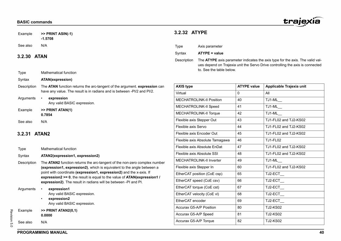
BASIC
PROG 40
Revision 5.0
3.2.3/i
3.2.3/i
Exam
See a
Type
Synta
Descr
Argum
Exam
See a
Type
Synta
Descr
Argum
Exam
See a
ameter indicates the axis type for the axis. The valid val-xia unit the Servo Drive controlling the axis is connected ow.
ATYPE value Applicable Trajexia unit
0 All
40 TJ1-ML__
41 TJ1-ML__
42 TJ1-ML__
43 TJ1-FL02 and TJ2-KS02
44 TJ1-FL02 and TJ2-KS02
45 TJ1-FL02 and TJ2-KS02
46 TJ1-FL02
47 TJ1-FL02 and TJ2-KS02
48 TJ1-FL02 and TJ2-KS02
49 TJ1-ML__
60 TJ1-FL02 and TJ2-KS02
65 TJ2-ECT__
66 TJ2-ECT__
67 TJ2-ECT__
68 TJ2-ECT__
69 TJ2-ECT__
80 TJ2-KS02
81 TJ2-KS02
82 TJ2-KS02
commands
RAMMING MANUAL
0 ATAN
1 ATAN2
3.2.32 ATYPE/i
/i
ple >> PRINT ASIN(-1)-1.5708
lso N/A
Mathematical function
x ATAN(expression)
iption The ATAN function returns the arc-tangent of the argument. expression can have any value. The result is in radians and is between -PI/2 and PI/2.
ents • expressionAny valid BASIC expression.
ple >> PRINT ATAN(1)0.7854
lso N/A
Mathematical function
x ATAN2(expression1, expression2)
iption The ATAN2 function returns the arc-tangent of the non-zero complex number (expression1, expression2), which is equivalent to the angle between a point with coordinate (expression1, expression2) and the x-axis. If expression2 >= 0, the result is equal to the value of ATAN(expression1 / expression2). The result in radians will be between -PI and PI.
ents • expression1Any valid BASIC expression.
• expression2Any valid BASIC expression.
ple >> PRINT ATAN2(0,1)0.0000
lso N/A
Type Axis parameter
Syntax ATYPE = value
Description The ATYPE axis parues depend on Trajeto. See the table bel
AXIS type
Virtual
MECHATROLINK-II Position
MECHATROLINK-II Speed
MECHATROLINK-II Torque
Flexible axis Stepper Out
Flexible axis Servo
Flexible axis Encoder Out
Flexible axis Absolute Tamagawa
Flexible axis Absolute EnDat
Flexible axis Absolute SSI
MECHATROLINK-II Inverter
Flexible axis Stepper In
EtherCAT position (CoE csp)
EtherCAT speed (CoE csv)
EtherCAT torque (CoE cst)
EtherCAT velocity (CoE vl)
EtherCAT encoder
Accurax G5-A/P Position
Accurax G5-A/P Speed
Accurax G5-A/P Torque
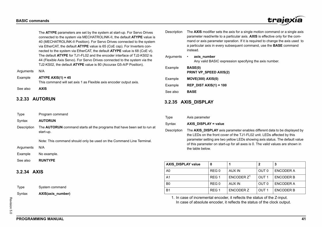
BASIC
PROG 41
Revision 5.0
/i
3.2.3/i
3.2.3/i
Argum
Exam
See a
Type
Synta
Descr
Argum
Exam
See a
Type
Synta
ets the axis for a single motion command or a single axis to a particular axis. AXIS is effective only for the com-ter operation. If it is required to change the axis used to
very subsequent command, use the BASE command
expression specifying the axis number.
XIS(2)
= 100
lue
axis parameter enables different data to be displayed by t cover of the TJ1-FL02 unit. LEDs affected by this
e two yellow LEDs showing axis status. The default value start-up for all axes is 0. The valid values are shown in
1 2 3
0 AUX IN OUT 0 ENCODER A
1 ENCODER Z1
coder, it reflects the status of the Z-input.der, it reflects the status of the clock output.
OUT 1 ENCODER B
0 AUX IN OUT 0 ENCODER A
1 ENCODER Z OUT 1 ENCODER B
commands
RAMMING MANUAL
3 AUTORUN
4 AXIS
3.2.35 AXIS_DISPLAY/i
/i
The ATYPE parameters are set by the system at start-up. For Servo Drives connected to the system via MECHATROLINK-II, the default ATYPE value is 40 (MECHATROLINK-II Position). For Servo Drives connected to the system via EtherCAT, the default ATYPE value is 65 (CoE csp). For Inverters con-nected to the system via EtherCAT, the default ATYPE value is 68 (CoE vl). The default ATYPE for TJ1-FL02 and the encoder interface of TJ2-KS02 is 44 (Flexible Axis Servo). For Servo Drives connected to the system via the TJ2-KS02, the default ATYPE value is 80 (Accurax G5-A/P Position).
ents N/A
ple ATYPE AXIS(1) = 45This command will set axis 1 as Flexible axis encoder output axis.
lso AXIS
Program command
x AUTORUN
iption The AUTORUN command starts all the programs that have been set to run at start-up.
Note: This command should only be used on the Command Line Terminal.
ents N/A
ple No example.
lso RUNTYPE
System command
x AXIS(axis_number)
Description The AXIS modifier sparameter read/writemand or axis paramea particular axis in einstead.
Arguments • axis_numberAny valid BASIC
Example BASE(0)PRINT VP_SPEED A
Example MOVE(300) AXIS(0)
Example REP_DIST AXIS(1)
See also BASE
Type Axis parameter
Syntax AXIS_DISPLAY = va
Description The AXIS_DISPLAYthe LEDs on the fronparameter setting arof this parameter onthe table below.
AXIS_DISPLAY value 0
A0 REG
A1 REG
1. In case of incremental enIn case of absolute enco
B0 REG
B1 REG
BASIC
PROG 42
Revision 5.0
/i
3.2.3/i
3.2.3/i
Argum
Exam
See a
Type
Synta
Descr
Argum
Exam
See a
Type
Synta
axis parameter is used to enable or disable particular f others. This parameter can be set ON or OFF for each default value on start-up is ON for all axes. The axis will XIS_ENABLE for that axis is ON and WDOG is on. For EtherCAT and TJ2-KS02 axes setting AXIS_ENABLE to vo Drive output to the motor. For Flexible axis Servo axis LE to OFF will force both voltage outputs to 0. For Flexi- and Encoder Out axes, setting AXIS_ENABLE to OFF eration on the outputs.
S(3) = OFFisable axis 3 independently of other axes in the system.
OUP
T(unit_number)] = offset_value
r the position of axes (on a per unit basis) when they are tart-up. The offsets are stored in Flash-ROM of the nly become active after the next start-up of after re-initial-k. The offset specified will be added to the node address -II, EtherCAT or TJ2-KS02 axes or will be used as a start-r an unused axis in case of Flexible axes.
e 0 to 6, with 0 being the unit immediately to the right of
uring axis number assignment for axes connected to the
T(1)=16nit in slot 1 will be assigned from axis 16 upwards.
commands
RAMMING MANUAL
6 AXIS_DPOS
7 AXIS_ENABLE
3.2.38 AXIS_OFFSET/i
ents N/A
ple AXIS_DISPLAY AXIS(2) = 2This command will display status of the outputs OUT 0 and OUT 1 allocated to axis 2.
lso N/A
Axis parameter (read-only)
x AXIS_DPOS
iption AXIS_DPOS is the axis demand position at output of FRAME transformation.AXIS_DPOS is normally equal to DPOS on each axis. The frame transforma-tion is therefore equivalent to 1:1 for each axis (FRAME = 0). For some machinery configurations it can be useful to install a frame transformation which is not 1:1, these are typically machines such as robotic arms or machines with parasitic motions on the axes. In this situation when FRAME is not zero AXIS_DPOS returns the demand position for the actual motor.Note:AXIS_DPOS can be scaled using AXIS_UNITS.
ents N/A
ple Return the axis position in user UNITS using the command line.>>PRINT AXIS_DPOS125.22>>
lso AXIS_UNITS, FRAME
Axis parameter
x AXIS_ENABLE = ON/OFF
Description The AXIS_ENABLEaxis independently oaxis individually. Thebe enabled if both AMECHATROLINK-II,OFF will disable Sersetting AXIS_ENABble axis Stepper Outwill block pulses gen
Arguments N/A
Example AXIS_ENABLE AXIThis command will d
See also AXIS, DISABLE_GR
Type System parameter
Syntax AXIS_OFFSET [SLO
Description Provides control oveassigned at system sTJ2-MC__ and will oization of the networof MECHATROLINKing point to search fo
Arguments • unit_numberUnit numbers arthe TJ2-MC__.
• offset_valueOffset applied dunit.
Example AXIS_OFFSET SLOAxes connected to u
See also SLOT
BASIC
PROG 43
Revision 5.0
3.2.3/i
Type
Synta
Descr
Argum
oint can move 90degrees. The encoder returns 400 and there is a 50:1 gearbox50/360
RS_LIMIT, AXIS_UNITS
limit may be set up in software thus allowing the program g range of the axis. This parameter holds the absolute e travel limit in user AXIS_UNITS.ATUS register is set when the axis position is greater IMIT.re only enabled when FRAME<>0 so that the user can tion of the motor/ joint.
reaches AXIS_RS_LIMIT the controller will CANCEL all E_GROUP, the axis will decelerate at DECEL or NC is also stopped. As this software limit uses quire a positive change in AXIS_DPOS to move off the
e a positive movement on DPOS due to the selected ion.
isabled when it has a value greater than REP_DIST or
oint can move 90 degrees. The encoder returns 400 and there is a 50:1 gearbox50/360
FS_LIMIT, AXIS_UNITS
commands
RAMMING MANUAL
9 AXIS_FS_LIMIT
3.2.40 AXIS_RS_LIMIT/i
WARNINGWhen using multiple TJ1-ML__ units, do not swap the MECHA-TROLINK-cables. This can result in a different axis allocation. This can result in serious injury and/or significant damage.
WARNINGAXIS_OFFSET is fixed to a unit number. Changing the position of the attached units can therefore result in a different axis allocation. This can result in serious injury and/or significant damage.
Axis parameter
x AXIS_FS_LIMIT
iption An axis end of travel limit may be set up in software thus allowing the program control of the working range of the axis. This parameter holds the absolute position of the forward travel limit in user AXIS_UNITS.Bit 16 of the AXISSTATUS register is set when the axis position is greater than the AXIS_FS_LIMIT.Axis software limits are only enabled when FRAME<>0 so that the user can limit the range of motion of the motor/ joint.Note:When AXIS_DPOS reaches AXIS_FS_LIMIT the controller will CANCEL all moves on the FRAME_GROUP, the axis will decelerate at DECEL or FAST_DEC. Any SYNC is also stopped. As this software limit uses AXIS_DPOS it will require a negative change in AXIS_DPOS to move off the limit. This may not be a negative movement on DPOS due to the selected FRAME transformation.Tip:AXIS_FS_LIMIT is disabled when it has a value greater than REP_DIST or when FRAME=0.
ents N/A
Example An arm on a robots jcounts per revolutionAXIS_UNITS=4000*AXIS_FS_LIMIT=0AXIS_RS_LIMIT=90
See also AXIS_DPOS, AXIS_
Type Axis parameter
Syntax AXIS_RS_LIMIT
Description An axis end of travelcontrol of the workinposition of the reversBit 17 of the AXISSTthan the AXIS_RS_LAxis software limits alimit the range of moNote:When AXIS_DPOS moves on the FRAMFAST_DEC. Any SYAXIS_DPOS it will relimit. This may not bFRAME transformatTip:AXIS_RS_LIMIT is dwhen FRAME=0.
Arguments N/A
Example An arm on a robots jcounts per revolutionAXIS_UNITS=4000*AXIS_FS_LIMIT=0AXIS_RS_LIMIT=90
See also AXIS_DPOS, AXIS_
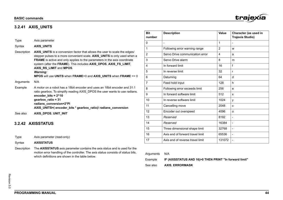
BASIC
PROG 44
Revision 5.0
3.2.4/i
3.2.4/i
Type
Synta
Descr
Argum
Exam
See a
Type
Synta
Descr
Value Character (as used in Trajexia Studio)
1 -
ng range 2 w
ication error 4 a
8 m
16 f
32 r
64 d
128 h
ds limit 256 e
mit 512 x
mit 1024 y
2048 c
ed 4096 o
8192 -
16384 -
ape limit 32768 -
avel limit 65536 -
avel limit 131072 -
D 16)>0 THEN PRINT "In forward limit"
commands
RAMMING MANUAL
1 AXIS_UNITS
2 AXISSTATUS
/i
/i
Axis parameter
x AXIS_UNITS
iption AXIS_UNITS is a conversion factor that allows the user to scale the edges/ stepper pulses to a more convenient scale. AXIS_UNITS is only used when a FRAME is active and only applies to the parameters in the axis coordinate system (after the FRAME). This includes AXIS_DPOS, AXIS_FS_LIMIT,AXIS_RS_LIMIT and MPOS.Warning:MPOS will use UNITS when FRAME=0 and AXIS_UNITS when FRAME <> 0
ents N/A
ple A motor on a robot has a 18bit encoder and uses an 18bit encoder and 31:1 ratio gearbox. To simplify reading AXIS_DPOS the user wants to use radians.encoder_bits = 2^10gearbox_ratio = 31radians_conversion=2*PIAXIS_UNITS=( encoder_bits * gearbox_ratio)/ radians_conversion
lso AXIS_DPOS, UNIT_INIT
Axis parameter (read-only)
x AXISSTATUS
iption The AXISSTATUS axis parameter contains the axis status and is used for the motion error handling of the controller. The axis status consists of status bits, which definitions are shown in the table below.
Bitnumber
Description
0 -
1 Following error warni
2 Servo Drive commun
3 Servo Drive alarm
4 In forward limit
5 In reverse limit
6 Datuming
7 Feed hold input
8 Following error excee
9 In forward software li
10 In reverse software li
11 Cancelling move
12 Encoder out overspe
13 Reserved
14 Reserved
15 Three dimensional sh
16 Axis end of forward tr
17 Axis end of reverse tr
Arguments N/A
Example IF (AXISSTATUS AN
See also AXIS, ERRORMASK
BASIC
PROG 45
Revision 5.0
3.2.4/i
Type
Synta
Descr
Argum
Exam
See a
F, distance, speed, accel)
mmand allows the parameters for the backlash compen-The backlash compensation is achieved as follows:is applied when the motor demand is in one direction. is reversed when the motor demand is in the opposite
perimposed on the command axis movements.nsation is applied after a change in the direction of the e backlash compensation can be seen in the meter, which is equal to DPOS + backlash compensa-
F.
nce, expressed in user units.
e compensation move, expressed in user units.
n or deceleration rate of the compensation move, er units.
,10,50) AXIS(0),8,50) AXIS(1)h compensation on axes 0 and 1.
S.
commands
RAMMING MANUAL
3 B_SPLINE 3.2.44 BACKLASH/i
Mathematical function
x B_SPLINE(type, data_in, number_in, data_out, expansion_ratio)
iption Expands an existing profile stored in the TABLE using the B-Spline mathemat-ical function. The expansion factor is configurable and the B_SPLINE stores expanded profile to another area in the TABLE.This is ideally used where the source CAM profile is too course and needs to be extrapolated into a greater number of points.
ents • typeReserved for future expansion. Always set this to 1.
• data_inLocation in the TABLE where the source profile is stored.
• number_inNumber of points in the source profile.
• data_outLocation in the TABLE where the expanded profile will be stored.
• expansion_ratioThe expansion ratio, i.e., if the source profile is 99 points and expansion_ratio is set to 10 the resulting profile will be 1000 point ((number_in+1) * expansion_ratio).
ple BASE(1)B_SPLINE(1, 0, 9, 200, 10)This command expands a 10 point profile in TABLE locations 0 to 9 to a larger 100 points profile starting at TABLE location 200.
lso N/A
Type Axis command
Syntax BACKLASH(ON/OF
Description The BACKLASH cosation to be loaded. • An offset move • The offset move
direction.
These moves are suThe backlash compeDPOS parameter. ThTRANS_DPOS paration.
Arguments • ON/OFFEither ON or OF
• distanceThe offset dista
• speedThe speed of th
• accelThe acceleratioexpressed in us
Example BACKLASH(ON,0.5BACKLASH(ON,0.4This applies backlas
See also DPOS, TRANS_DPO
BASIC
PROG 46
Revision 5.0
3.2.4/i
3.2.4/i
Type
Synta
Descr
Argum
Exam
See a
Type
Synta
d is used to set the default base axis or to set a specified . All subsequent motion commands and axis parameters axis or the specified axis group unless the AXIS com-ify a temporary base axis. The base axis or axis group is
anged again with BASE. can have its own axis group and each program can set
dependently. Use the PROC modifier to access the tain task.uping can be set by explicitly assigning the order of axes. r interpolation purposes in multi-axes linear and circular or the base axis group is (0,1,2 ... 62,63) at start-up or ts running on a task. The BASE command without any e current base order grouping.mmand does not specify all the axes, the BASE com-remaining values automatically. Firstly it will fill in any e the last declared value, then it will fill in any remaining
ts the internal array of 64 axes to:5 ... ,61,62,63,0,1,3,4,5,7,8,9.
mand without any arguments should only be used on erminal.
ke up to 64 arguments.
he axis set as the base axis and any subsequent axes in for multi-axis moves.
y must use ascending values.
unit conversion factor for axis 1peed for axis 1 acceleration rate for axis 1
unit conversion factor for axis 2peed for axis 2t acceleration rate for axis 2
ram each axis with its own speed, acceleration and other
commands
RAMMING MANUAL
5 BACKLASH_DIST
6 BASE
Axis parameter
x BACKLASH_DIST
iption BACKLASH_DIST is the amount of backlash compensation that is applied to the axis when BACKLASH = ON.
ents N/A
ple IF BACKLASH_DIST>100 THEN OP (10, ON) ' show that backlash compensation reached this valueELSE OP (10, OFF)END IF
lso BACKLASH
Axis command
x BASEBASE(axis_1 [ ,axis_2 [ , axis_3 [ , axis_4 [ , axis_...]]]])BABA(axis_1 [ ,axis_2 [ , axis_3 [ , axis_4 [ , axis_...]]]])
Description The BASE commanaxis sequence groupwill apply to the basemand is used to speceffective until it is chEach BASIC processits own axis group inparameters for a cerThe BASE order groThis order is used fomoves. The default fwhen a program stararguments returns thNote: If the BASE comand will “fill in” the remaining axes abovaxes in sequence.So BASE(2,6,10) se2,6,10,11,12,13,14,1
Note: The BASE comthe Command Line T
Arguments The command can ta• axis_i
The number of tthe group order
Note: The BASE arra
Example BASE(1)UNITS = 2000 ' Set SPEED = 100 ' Set sACCEL = 5000 ' SetBASE(2)UNITS = 2000 ' Set SPEED = 125 ' Set sACCEL = 10000 ' SeIt is possible to progparameters.
BASIC
PROG 47
Revision 5.0
3.2.4/i
Exam
Exam
Exam
Exam
See a
Type
Synta
Descr
Argum
GOTO error_routine
ENr "; RUN_ERROR[0];
in line "; ERROR_LINE[0]
BASIC program in this example, the error routine will be
resent to prevent the program going into error routine rmally.
RUN_ERROR.
ead-only)
ns the current state of the battery condition. If N then the battery needs to be changed. If FF then battery condition is ok.
ogram_name"
dio to remove all break points from the specified pro-
commands
RAMMING MANUAL
7 BASICERROR
3.2.48 BATTERY_LOW/i
3.2.49 BREAK_RESET/i
ple BASE(0)MOVE(100,-23.1,1250)In this example, axes 0, 1 and 2 will move to the specified positions at the interpolated speed and acceleration set for axis 0. BASE(0) sets the base axis to axis 0, which determines the three axes used by MOVE and the speed and acceleration rate.
ple >> BASE(0,2,1)On the command line the base group order can be shown by typing BASE.
ple >> RUN "PROGRAM", 3>> BASE PROC(3)(0,2,1)Use the PROC modifier to show the base group order of a certain task.
ple >> BASE(2)>> PRINT BASE2.0000Printing BASE will return the current selected base axis.
lso AXIS
System command
x BASICERROR
iption The BASICERROR command can be used to run a routine when a run-time error occurs in a program. BASICERROR can only be used as part of an ON ... GOSUB or ON ... GOTO command. This command is required to be exe-cuted once in the BASIC program. If several commands are used only the one executed last is effective.
ents N/A
Example ON BASICERROR ... no_error = 1 STOPerror_routine: IF no_error = 0 TH PRINT "The erro PRINT " occurred ENDIF STOPIf an error occurs in aexecuted.The IF statement is pwhen it is stopped no
See also ERROR_LINE, ON,
Type System parameter (r
Syntax BATTERY_LOW
Description This parameter returBATTERY_LOW=OBATTERY_LOW=O
Arguments N/A
Example No example.
See also N/A
Type System command
Syntax BREAK_RESET "pr
Description Used by Trajexia Stugram.
BASIC
PROG 48
Revision 5.0
3.2.5/i
Argum
Exam
See a
Type
Synta
Descr
the first element in the TABLE array to be used.ecify the start point allows the TABLE array to hold more and/or other information.
the end element in the TABLE array.rlier value used to scale the values stored in the TABLE.
ues are specified in encoder edges, use this argument to r instance to the unit conversion factor (set by UNITS
user units that controls the speed of movement through ime taken to execute CAM depends on the current axis istance. For example, assume the system is being pro- and the speed is set to 10 mm/s and the acceleration
. If a distance of 100 mm is specified, CAM will take xecute.ameter in the base axis allows modification of the speed en using the CAM move.
M command is executing, the ENDMOVE parameter is previous move.
commands
RAMMING MANUAL
0 CAM
ents • program_nameThe name of the program from which you want to remove all break points.
ple BREAK_RESET "simpletest"Will remove all break points from program simpletest.
lso N/A
Axis command
x CAM(start_point, end_point, table_multiplier, distance)
iption The CAM command is used to generate movement of an axis following a position profile which is stored in the TABLE variable array. The TABLE val-ues are absolute positions relative to the starting point and are specified in encoder edges. The TABLE array is specified with the TABLE command.The movement can be defined with any number of points from 3 to the maxi-mum table size available (500000). The TJ2-MC__ moves continuously between the values in the TABLE to allow a number of points to define a smooth profile. Two or more CAM commands can be executed simultane-ously using the same or overlapping values in the TABLE array. The TABLE profile is traversed once.The distance argument together with the SPEED and ACCEL parameters determine the speed moving through the TABLE array. Note that in order to follow the CAM profile exactly the ACCEL parameter of the axis must be at least 1000 times larger than the SPEED parameter.CAM works on the default basis axis (set with BASE) unless AXIS is used to specify a temporary base axis.
Arguments • start_pointThe address of Being able to spthan one profile
• end_pointThe address of
• table_multiplieThe Table multipAs the Table valset the values foparameter).
• distanceA factor given inthe Table. The tspeed and this dgrammed in mmsufficiently high10 seconds to eThe SPEED parof movement wh
Note: When the CAset to the end of the
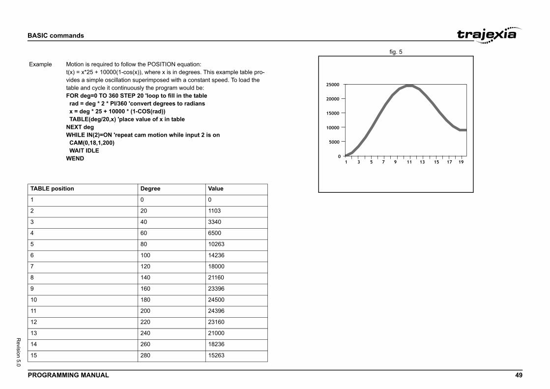
BASIC
PROG 49
Revision 5.0
fig. 5/i
/i
Exam
TABL
1
2
3
4
5
6
7
8
9
10
11
12
13
14
15
commands
RAMMING MANUAL
ple Motion is required to follow the POSITION equation:t(x) = x*25 + 10000(1-cos(x)), where x is in degrees. This example table pro-vides a simple oscillation superimposed with a constant speed. To load the table and cycle it continuously the program would be:FOR deg=0 TO 360 STEP 20 'loop to fill in the table rad = deg * 2 * PI/360 'convert degrees to radians x = deg * 25 + 10000 * (1-COS(rad)) TABLE(deg/20,x) 'place value of x in tableNEXT degWHILE IN(2)=ON 'repeat cam motion while input 2 is on CAM(0,18,1,200) WAIT IDLEWEND
E position Degree Value
0 0
20 1103
40 3340
60 6500
80 10263
100 14236
120 18000
140 21160
160 23396
180 24500
200 24396
220 23160
240 21000
260 18236
280 15263
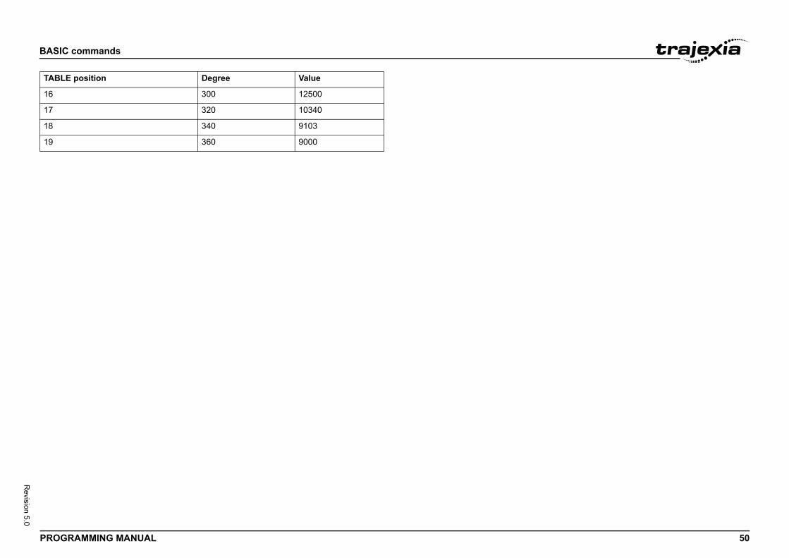
BASIC
PROG 50
Revision 5.0
16
17
18
19
TABL
commands
RAMMING MANUAL
300 12500
320 10340
340 9103
360 9000
E position Degree Value
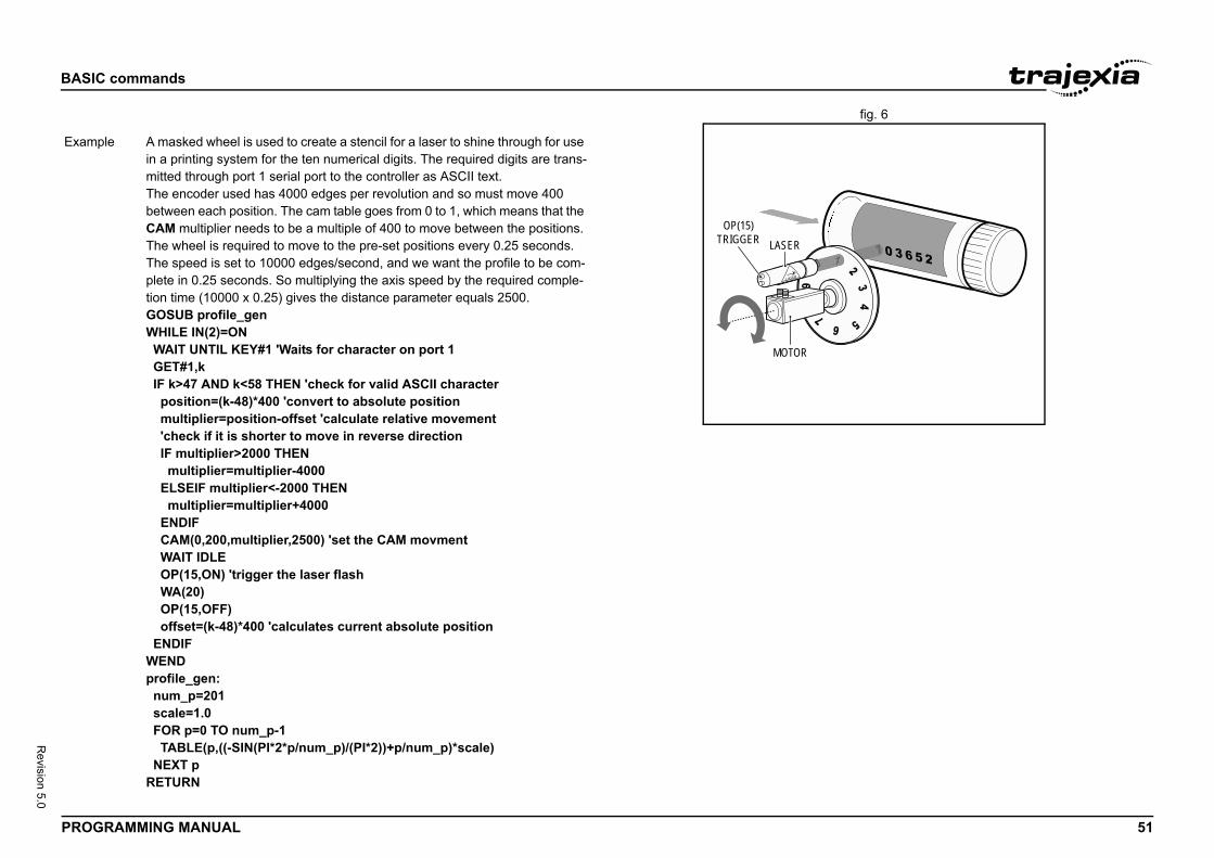
BASIC
PROG 51
Revision 5.0
fig. 6/i
Exam
commands
RAMMING MANUAL
LASER
MOTOR
OP(15)TRIGGER
ple A masked wheel is used to create a stencil for a laser to shine through for use in a printing system for the ten numerical digits. The required digits are trans-mitted through port 1 serial port to the controller as ASCII text.The encoder used has 4000 edges per revolution and so must move 400 between each position. The cam table goes from 0 to 1, which means that the CAM multiplier needs to be a multiple of 400 to move between the positions.The wheel is required to move to the pre-set positions every 0.25 seconds. The speed is set to 10000 edges/second, and we want the profile to be com-plete in 0.25 seconds. So multiplying the axis speed by the required comple-tion time (10000 x 0.25) gives the distance parameter equals 2500.GOSUB profile_genWHILE IN(2)=ON WAIT UNTIL KEY#1 'Waits for character on port 1 GET#1,k IF k>47 AND k<58 THEN 'check for valid ASCII character position=(k-48)*400 'convert to absolute position multiplier=position-offset 'calculate relative movement 'check if it is shorter to move in reverse direction IF multiplier>2000 THEN multiplier=multiplier-4000 ELSEIF multiplier<-2000 THEN multiplier=multiplier+4000 ENDIF CAM(0,200,multiplier,2500) 'set the CAM movment WAIT IDLE OP(15,ON) 'trigger the laser flash WA(20) OP(15,OFF) offset=(k-48)*400 'calculates current absolute position ENDIFWENDprofile_gen: num_p=201 scale=1.0 FOR p=0 TO num_p-1 TABLE(p,((-SIN(PI*2*p/num_p)/(PI*2))+p/num_p)*scale) NEXT pRETURN
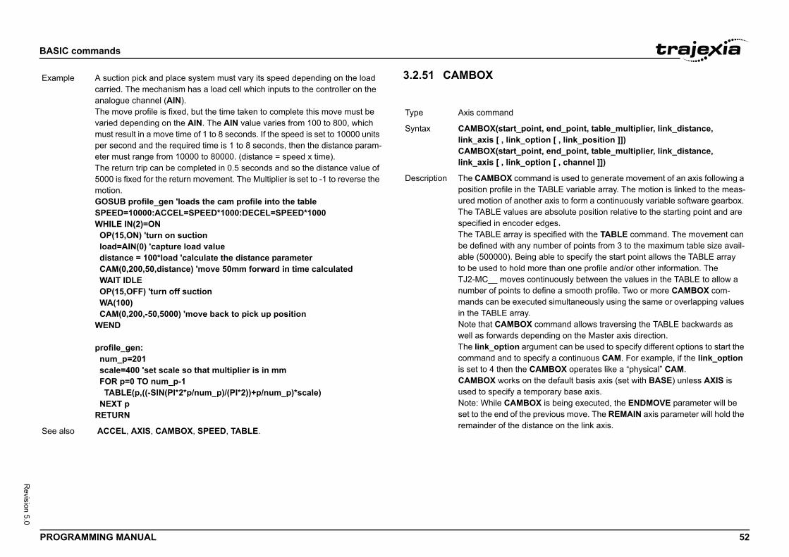
BASIC
PROG 52
Revision 5.0
Exam
See a
nt, end_point, table_multiplier, link_distance, tion [ , link_position ]])nt, end_point, table_multiplier, link_distance, tion [ , channel ]])
and is used to generate movement of an axis following a TABLE variable array. The motion is linked to the meas-er axis to form a continuously variable software gearbox. re absolute position relative to the starting point and are edges.specified with the TABLE command. The movement can number of points from 3 to the maximum table size avail- able to specify the start point allows the TABLE array ore than one profile and/or other information. The ntinuously between the values in the TABLE to allow a efine a smooth profile. Two or more CAMBOX com-ted simultaneously using the same or overlapping values
command allows traversing the TABLE backwards as ending on the Master axis direction.ument can be used to specify different options to start the cify a continuous CAM. For example, if the link_option AMBOX operates like a “physical” CAM.the default basis axis (set with BASE) unless AXIS is porary base axis.X is being executed, the ENDMOVE parameter will be
previous move. The REMAIN axis parameter will hold the ance on the link axis.
commands
RAMMING MANUAL
3.2.51 CAMBOX/i
ple A suction pick and place system must vary its speed depending on the load carried. The mechanism has a load cell which inputs to the controller on the analogue channel (AIN).The move profile is fixed, but the time taken to complete this move must be varied depending on the AIN. The AIN value varies from 100 to 800, which must result in a move time of 1 to 8 seconds. If the speed is set to 10000 units per second and the required time is 1 to 8 seconds, then the distance param-eter must range from 10000 to 80000. (distance = speed x time).The return trip can be completed in 0.5 seconds and so the distance value of 5000 is fixed for the return movement. The Multiplier is set to -1 to reverse the motion.GOSUB profile_gen 'loads the cam profile into the tableSPEED=10000:ACCEL=SPEED*1000:DECEL=SPEED*1000WHILE IN(2)=ON OP(15,ON) 'turn on suction load=AIN(0) 'capture load value distance = 100*load 'calculate the distance parameter CAM(0,200,50,distance) 'move 50mm forward in time calculated WAIT IDLE OP(15,OFF) 'turn off suction WA(100) CAM(0,200,-50,5000) 'move back to pick up positionWEND
profile_gen: num_p=201 scale=400 'set scale so that multiplier is in mm FOR p=0 TO num_p-1 TABLE(p,((-SIN(PI*2*p/num_p)/(PI*2))+p/num_p)*scale) NEXT pRETURN
lso ACCEL, AXIS, CAMBOX, SPEED, TABLE.
Type Axis command
Syntax CAMBOX(start_poilink_axis [ , link_opCAMBOX(start_poilink_axis [ , link_op
Description The CAMBOX commposition profile in theured motion of anothThe TABLE values aspecified in encoderThe TABLE array is be defined with any able (500000). Beingto be used to hold mTJ2-MC__ moves conumber of points to dmands can be execuin the TABLE array.Note that CAMBOX well as forwards depThe link_option argcommand and to speis set to 4 then the CCAMBOX works on used to specify a temNote: While CAMBOset to the end of the remainder of the dist
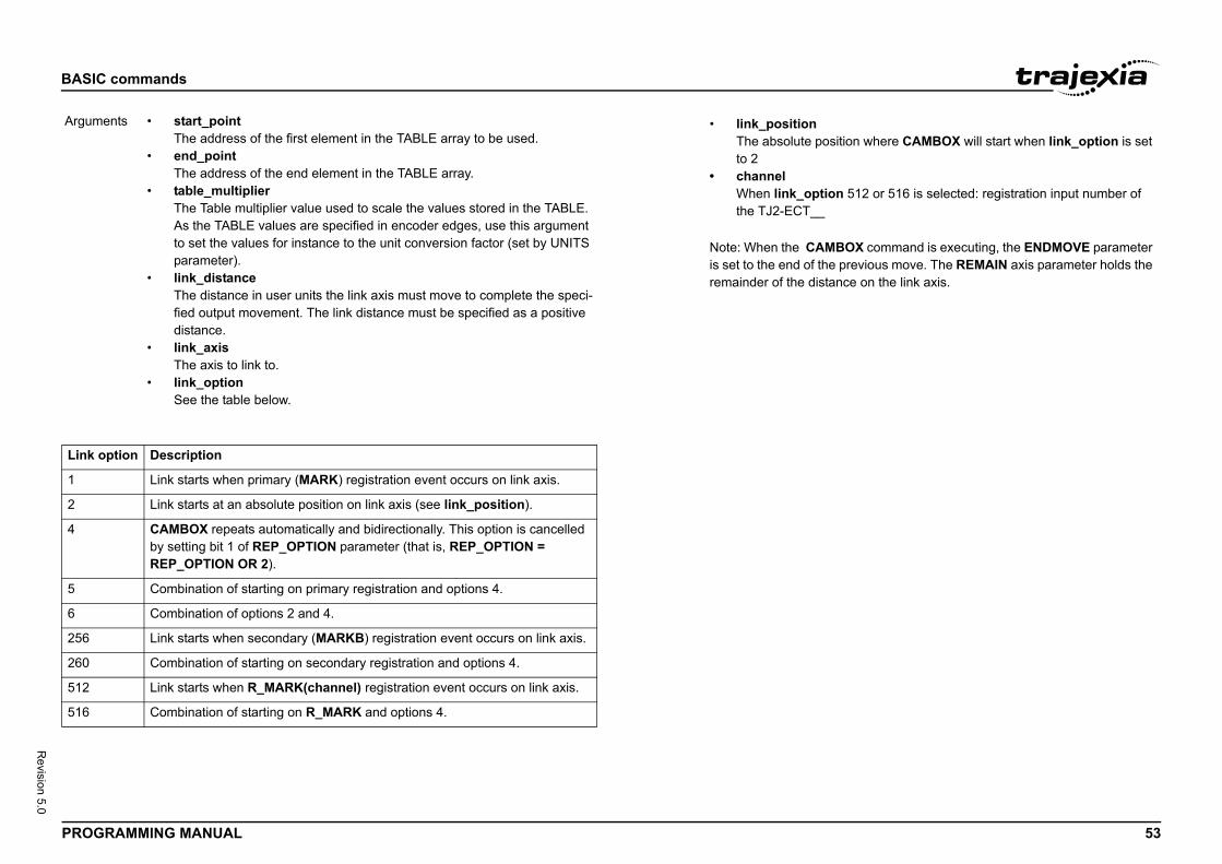
BASIC
PROG 53
Revision 5.0
/i
Argum
Link
1
2
4
5
6
256
260
512
516
sition where CAMBOX will start when link_option is set
on 512 or 516 is selected: registration input number of
BOX command is executing, the ENDMOVE parameter e previous move. The REMAIN axis parameter holds the ance on the link axis.
commands
RAMMING MANUAL
/i
ents • start_pointThe address of the first element in the TABLE array to be used.
• end_pointThe address of the end element in the TABLE array.
• table_multiplierThe Table multiplier value used to scale the values stored in the TABLE. As the TABLE values are specified in encoder edges, use this argument to set the values for instance to the unit conversion factor (set by UNITS parameter).
• link_distanceThe distance in user units the link axis must move to complete the speci-fied output movement. The link distance must be specified as a positive distance.
• link_axisThe axis to link to.
• link_optionSee the table below.
option Description
Link starts when primary (MARK) registration event occurs on link axis.
Link starts at an absolute position on link axis (see link_position).
CAMBOX repeats automatically and bidirectionally. This option is cancelled by setting bit 1 of REP_OPTION parameter (that is, REP_OPTION = REP_OPTION OR 2).
Combination of starting on primary registration and options 4.
Combination of options 2 and 4.
Link starts when secondary (MARKB) registration event occurs on link axis.
Combination of starting on secondary registration and options 4.
Link starts when R_MARK(channel) registration event occurs on link axis.
Combination of starting on R_MARK and options 4.
• link_positionThe absolute poto 2
• channelWhen link_optithe TJ2-ECT__
Note: When the CAMis set to the end of thremainder of the dist
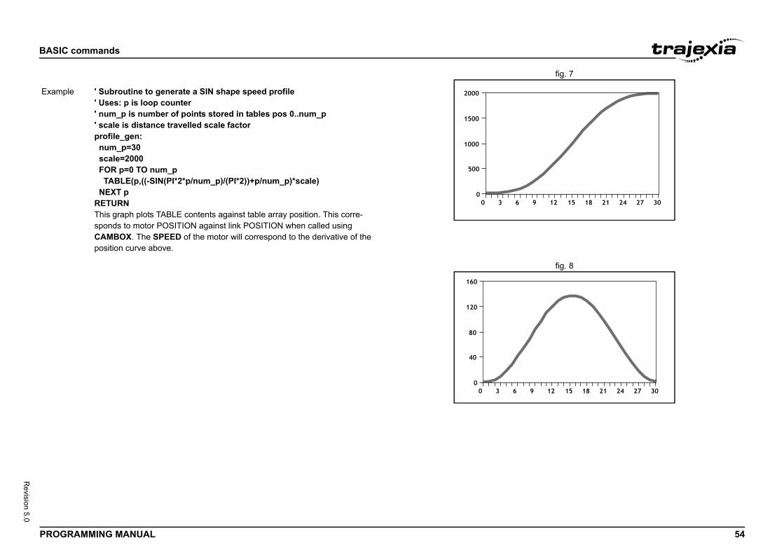
BASIC
PROG 54
Revision 5.0
fig. 7/i
fig. 8
Exam
commands
RAMMING MANUAL
ple ' Subroutine to generate a SIN shape speed profile' Uses: p is loop counter' num_p is number of points stored in tables pos 0..num_p' scale is distance travelled scale factorprofile_gen: num_p=30 scale=2000 FOR p=0 TO num_p TABLE(p,((-SIN(PI*2*p/num_p)/(PI*2))+p/num_p)*scale) NEXT pRETURNThis graph plots TABLE contents against table array position. This corre-sponds to motor POSITION against link POSITION when called using CAMBOX. The SPEED of the motor will correspond to the derivative of the position curve above.
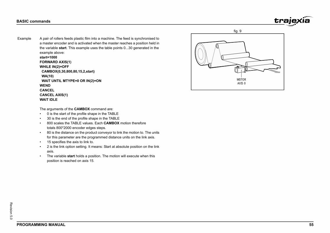
BASIC
PROG 55
Revision 5.0
fig. 9/i
MOTORAXIS 0
Exam
commands
RAMMING MANUAL
ple A pair of rollers feeds plastic film into a machine. The feed is synchronised to a master encoder and is activated when the master reaches a position held in the variable start. This example uses the table points 0...30 generated in the example above:start=1000FORWARD AXIS(1)WHILE IN(2)=OFF CAMBOX(0,30,800,80,15,2,start) WA(10) WAIT UNTIL MTYPE=0 OR IN(2)=ONWENDCANCELCANCEL AXIS(1)WAIT IDLE
The arguments of the CAMBOX command are:• 0 is the start of the profile shape in the TABLE• 30 is the end of the profile shape in the TABLE• 800 scales the TABLE values. Each CAMBOX motion therefore
totals 800*2000 encoder edges steps.• 80 is the distance on the product conveyor to link the motion to. The units
for this parameter are the programmed distance units on the link axis.• 15 specifies the axis to link to.• 2 is the link option setting. It means: Start at absolute position on the link
axis.• The variable start holds a position. The motion will execute when this
position is reached on axis 15.
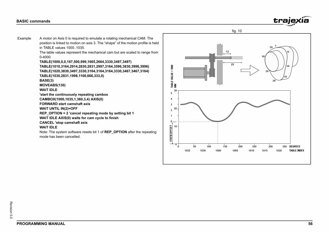
BASIC
PROG 56
Revision 5.0
fig. 10/i
DEGREESTABLE INDEX
Exam
commands
RAMMING MANUAL
TABL
E VA
LUE
× 100
0MM
STAT
ICOF
FSET
ple A motor on Axis 0 is required to emulate a rotating mechanical CAM. The position is linked to motion on axis 3. The “shape” of the motion profile is held in TABLE values 1000..1035.The table values represent the mechanical cam but are scaled to range from 0-4000.TABLE(1000,0,0,167,500,999,1665,2664,3330,3497,3497)TABLE(1010,3164,2914,2830,2831,2997,3164,3596,3830,3996,3996)TABLE(1020,3830,3497,3330,3164,3164,3164,3330,3467,3467,3164)TABLE(1030,2831,1998,1166,666,333,0)BASE(3)MOVEABS(130)WAIT IDLE'start the continuously repeating camboxCAMBOX(1000,1035,1,360,3,4) AXIS(0)FORWARD start camshaft axisWAIT UNTIL IN(2)=OFFREP_OPTION = 2 'cancel repeating mode by setting bit 1WAIT IDLE AXIS(0) waits for cam cycle to finishCANCEL 'stop camshaft axisWAIT IDLENote: The system software resets bit 1 of REP_OPTION after the repeating mode has been cancelled.
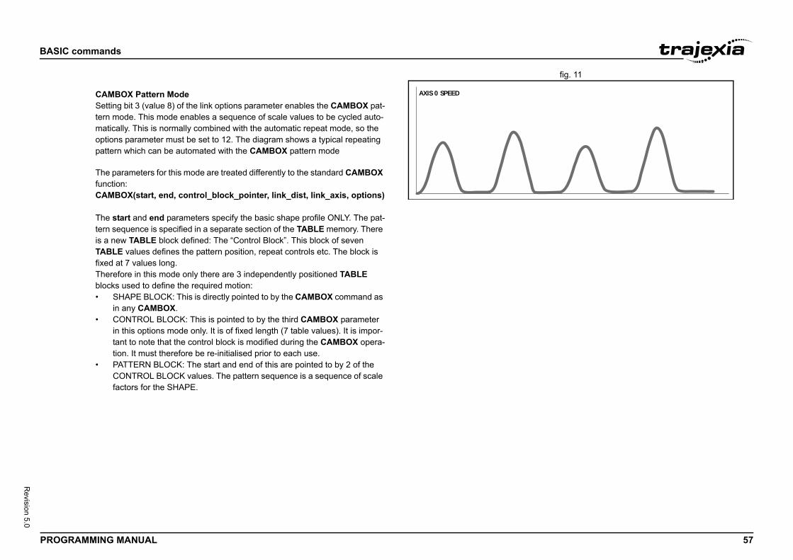
BASIC
PROG 57
Revision 5.0
fig. 11
commands
RAMMING MANUAL
AXIS 0 SPEEDCAMBOX Pattern ModeSetting bit 3 (value 8) of the link options parameter enables the CAMBOX pat-tern mode. This mode enables a sequence of scale values to be cycled auto-matically. This is normally combined with the automatic repeat mode, so the options parameter must be set to 12. The diagram shows a typical repeating pattern which can be automated with the CAMBOX pattern mode
The parameters for this mode are treated differently to the standard CAMBOX function:CAMBOX(start, end, control_block_pointer, link_dist, link_axis, options)
The start and end parameters specify the basic shape profile ONLY. The pat-tern sequence is specified in a separate section of the TABLE memory. There is a new TABLE block defined: The “Control Block”. This block of seven TABLE values defines the pattern position, repeat controls etc. The block is fixed at 7 values long.Therefore in this mode only there are 3 independently positioned TABLE blocks used to define the required motion:• SHAPE BLOCK: This is directly pointed to by the CAMBOX command as
in any CAMBOX.• CONTROL BLOCK: This is pointed to by the third CAMBOX parameter
in this options mode only. It is of fixed length (7 table values). It is impor-tant to note that the control block is modified during the CAMBOX opera-tion. It must therefore be re-initialised prior to each use.
• PATTERN BLOCK: The start and end of this are pointed to by 2 of the CONTROL BLOCK values. The pattern sequence is a sequence of scale factors for the SHAPE.
BASIC
PROG 58
Revision 5.0
commands
RAMMING MANUAL
NOTENegative motion on link axis:The axis the CAMBOX is linked to may be running in a positive or negative direction. In the case of a negative direction link the pat-tern will execute in reverse. In the case where a certain number of pattern repeats is specified with a negative direction link, the first control block will produce one repeat less than expected. This is because the CAMBOX loads a zero link position which immedi-ately goes negative on the next servo cycle triggering a REPEAT COUNT. This effect only occurs when the CAMBOX is loaded, not on transitions from CONTROL BLOCK to CONTROL BLOCK. This effect can easily be compensated for either by increasing the required number of repeats, or setting the initial value of REPEAT POSITION to 1.
Control Block Parameters:• start: The start position of the shape block in the TABLE• end: The end position of the shape block in the TABLE• control_block_pointer: The position in the table of the 7 point control
block• link_dist: The distance the link axis must move to complete CAMBOX
profile• link_axis: The axis to link to.• options: As CAMBOX, bit 3 must be enabled
The table below gives the CONTROL BLOCK parametersNote: R/W values can be written to by the user program during the pattern CAMBOX execution.
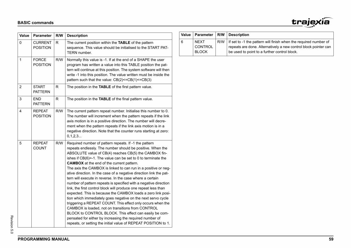
BASIC
PROG 59
Revision 5.0
Value
0
1
2
3
4
5
to -1 the pattern will finish when the required number of ts are done. Alternatively a new control block pointer can ed to point to a further control block.
ription
commands
RAMMING MANUAL
Parameter R/W Description
CURRENTPOSITION
R The current position within the TABLE of the pattern sequence. This value should be initialised to the START PAT-TERN number.
FORCEPOSITION
R/W Normally this value is -1. If at the end of a SHAPE the user program has written a value into this TABLE position the pat-tern will continue at this position. The system software will then write -1 into this position. The value written must be inside the pattern such that the value: CB(2)<=CB(1)<=CB(3)
STARTPATTERN
R The position in the TABLE of the first pattern value.
ENDPATTERN
R The position in the TABLE of the final pattern value.
REPEATPOSITION
R/W The current pattern repeat number. Initialise this number to 0. The number will increment when the pattern repeats if the link axis motion is in a positive direction. The number will decre-ment when the pattern repeats if the link axis motion is in a negative direction. Note that the counter runs starting at zero: 0,1,2,3...
REPEATCOUNT
R/W Required number of pattern repeats. If -1 the patternrepeats endlessly. The number should be positive. When the ABSOLUTE value of CB(4) reaches CB(5) the CAMBOX fin-ishes if CB(6)=-1. The value can be set to 0 to terminate the CAMBOX at the end of the current pattern.The axis the CAMBOX is linked to can run in a positive or neg-ative direction. In the case of a negative direction link the pat-tern will execute in reverse. In the case where a certain number of pattern repeats is specified with a negative direction link, the first control block will produce one repeat less than expected. This is because the CAMBOX loads a zero link posi-tion which immediately goes negative on the next servo cycle triggering a REPEAT COUNT. This effect only occurs when the CAMBOX is loaded, not on transitions from CONTROL BLOCK to CONTROL BLOCK. This effect can easily be com-pensated for either by increasing the required number of repeats, or setting the initial value of REPEAT POSITION to 1.
6 NEXTCONTROLBLOCK
R/W If set repeabe us
Value Parameter R/W Desc
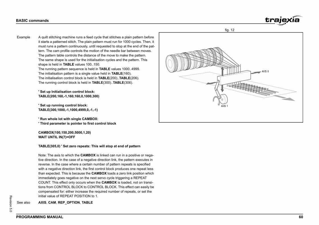
BASIC
PROG 60
Revision 5.0
fig. 12/i
AXIS 1
AXIS 0
Exam
See a
commands
RAMMING MANUAL
ple A quilt stitching machine runs a feed cycle that stitches a plain pattern before it starts a patterned stitch. The plain pattern must run for 1000 cycles. Then, it must runs a pattern continuously, until requested to stop at the end of the pat-tern. The cam profile controls the motion of the needle bar between moves. The pattern table controls the distance of the move to make the pattern.The same shape is used for the initialisation cycles and the pattern. This shape is held in TABLE values 100..150.The running pattern sequence is held in TABLE values 1000..4999.The initialisation pattern is a single value held in TABLE(160).The initialisation control block is held in TABLE(200)..TABLE(206).The running control block is held in TABLE(300)..TABLE(306).
' Set up Initialisation control block:TABLE(200,160,-1,160,160,0,1000,300)
' Set up running control block:TABLE(300,1000,-1,1000,4999,0,-1,-1)
' Run whole lot with single CAMBOX:' Third parameter is pointer to first control block
CAMBOX(100,150,200,5000,1,20)WAIT UNTIL IN(7)=OFF
TABLE(305,0) ' Set zero repeats: This will stop at end of pattern
Note: The axis to which the CAMBOX is linked can run in a positive or nega-tive direction. In the case of a negative direction link, the pattern executes in reverse. In the case where a certain number of pattern repeats is specified with a negative direction link, the first control block produces one repeat less than expected. This is because the CAMBOX loads a zero link position which immediately goes negative on the next servo cycle triggering a REPEAT COUNT. This effect only occurs when the CAMBOX is loaded, not on transi-tions from CONTROL BLOCK to CONTROL BLOCK. This effect can easily be compensated for: either increase the required number of repeats, or set the initial value of REPEAT POSITION to 1.
lso AXIS, CAM, REP_OPTION, TABLE
BASIC
PROG 61
Revision 5.0
3.2.5/i
Type
Synta
mands where the second argument is 4 through 10 are ASIC program that is run at startup. The sequence of the nds that configure a CANopen network is important.
umber of the unit.
he CAN bus. Valid values are 2 (500 Kbps), (125 Kbps), 5 (50 Kbps) and 6 (20 Kbps).
ode on the CAN bus.gflag of the node. l, no error occurs when the node is not in the network.ory, an error occurs when the node is not in the network.
an individual PDO. PDO_number can range from 0 to 7.
a in Trajexia: 1 = VR, 2 = TABLE, 3 = Digital I/O,
in the VR, TABLE, IN, OP, AIN or AOUT array.
roller Object Identification) ID used to identify a PDO in a rk.
bject type. Valid values are: 2 = INT8, 3 = INT16, INT8, 6 = UINT16, 7 = UINT32.
me in 0.1 ms units between two consecutive transmis-.
ime in ms units that is observed between two consecu-ns of a TPDO. If this value is 0, the time is unlimited. The ly when the contents changes.
addressed CANopen object.
ithin the addressed CANopen object.
commands
RAMMING MANUAL
2 CAN_CORT
System command
x CAN_CORT(unit,4,0)Retrieves the unit status. See the table in section 4.6.2.CAN_CORT(unit,5,bit_rate)Initialises the TJ1-CORT with the desired bit rate.CAN_CORT(unit,6,node_ID,mandatory_flag)Add a slave node to the TJ1-CORT and indicate whether it is permanently available on the network.CAN_CORT(unit,7,PDO_number,area_type,start_address,COB_ID, obj_type, obj_type,…)Configure an RPDO.CAN_CORT(unit,8,PDO_number,area_type,start_address,COB_ID, inhibit_time,event_timer,obj_type, obj_type,…)Configure a TPDO.CAN_CORT(unit,9,node_ID,index,subindex,byte1,byte2,…)Make the TJ1-CORT configure an object in a slave during the CANopen net-work initialization.CAN_CORT(unit,10)Start the CANopen network and map the Trajexia memory to RPDOs and TPDOs.CAN_CORT(unit,11,mode)Set the CANopen network to pre-operational or operational state.CAN_CORT(unit,12,node_ID,index,subindex,VR_address)Reads the value of a CANopen node object using an SDO (Service Data Object) command into the VR array. Each byte of the returned value occupies one VR address.CAN_CORT(unit,13,node_ID,index,subindex,VR_address,data_len)Write a value of a CANopen node object using an SDO command using the VR array as source. Each VR address is interpreted as one byte of the value that is written.CAN_CORT(unit,14,node_ID,VR_address)Reads the EMCY (emergency) message from a node into the VR array. Each byte of the eight bytes occupies one VR address.
Description The CAN_CORT comnormally used in a BCAN_CORT comma
Arguments • unitThe sequence n
• bit_rateThe bit rate on t3 (250 Kbps), 4
• node_IDThe CANopen n
• mandatory_flaThe mandatory - 0 = optiona- 1= mandat
• PDO_numberIdentification of
• area_typeThe memory are4 = Analog I/O.
• start_addressThe array index
• COB_IDThe COB (ContCANopen netwo
• obj_typeThe CANopen o4 = INT32, 5 = U
• inhibit_timeThe minimum tisions of a TPDO
• event_timerThe maximum ttive transmissioTPDO is sent on
• indexThe index of the
• subindexThe subindex w
BASIC
PROG 62
Revision 5.0
3.2.5/i
Exam
See a
Type
Synta
Descr
Argum
commands
RAMMING MANUAL
3 CANCEL
• modeThe CANopen network operation mode. 0 = pre-operational, 1 = opera-tional.
• VR_addressThe index in the VR array.
• data_lenThe amount of bytes to transfer.
ple No example.
lso N/A
Axis command
x CANCEL[(mode)]
iption The CANCEL command cancels the move on an axis or an interpolating axis group. Speed-profiled moves (FORWARD, REVERSE, MOVE, MOVEABS, MOVECIRC, MHELICAL and MOVEMODIFY) will be decelerated at the deceleration rate as set by the DECEL parameter and then stopped. Other moves will be immediately stopped.CANCEL works on the default basis axis (set with BASE) unless AXIS is used to specify a temporary base axis.Note:• CANCEL cancels only the presently executing move. If further moves are
buffered they will then be loaded.• During the deceleration of the current move additional CANCELs will be
ignored.• CANCEL(1) cancels only the presently buffered move. Any moves stored
in the task buffers indicated by the PMOVE variable can be loaded into the buffer as soon as the buffered move is cancelled.
ents • mode0 = Cancels axis commands from the MTYPE buffer. Can be used with-out the parameter1 = Cancels all buffered axis commands.2 = Cancels all current and buffered axis commands.
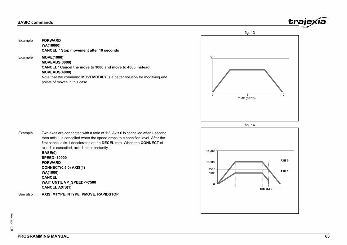
BASIC
PROG 63
Revision 5.0
fig. 13/i
fig. 14/i
TIME (SECS)
Exam
Exam
AXIS 0
AXIS 1
1000 MSEC
Exam
See a
commands
RAMMING MANUAL
ple FORWARDWA(10000)CANCEL ' Stop movement after 10 seconds
ple MOVE(1000)MOVEABS(3000)CANCEL ' Cancel the move to 3000 and move to 4000 instead.MOVEABS(4000)Note that the command MOVEMODIFY is a better solution for modifying end points of moves in this case.
ple Two axes are connected with a ratio of 1:2. Axis 0 is cancelled after 1 second, then axis 1 is cancelled when the speed drops to a specified level. After the first cancel axis 1 decelerates at the DECEL rate. When the CONNECT of axis 1 is cancelled, axis 1 stops instantly.BASE(0)SPEED=10000FORWARDCONNECT(0.5,0) AXIS(1)WA(1000)CANCELWAIT UNTIL VP_SPEED<=7500CANCEL AXIS(1)
lso AXIS, MTYPE, NTYPE, PMOVE, RAPIDSTOP
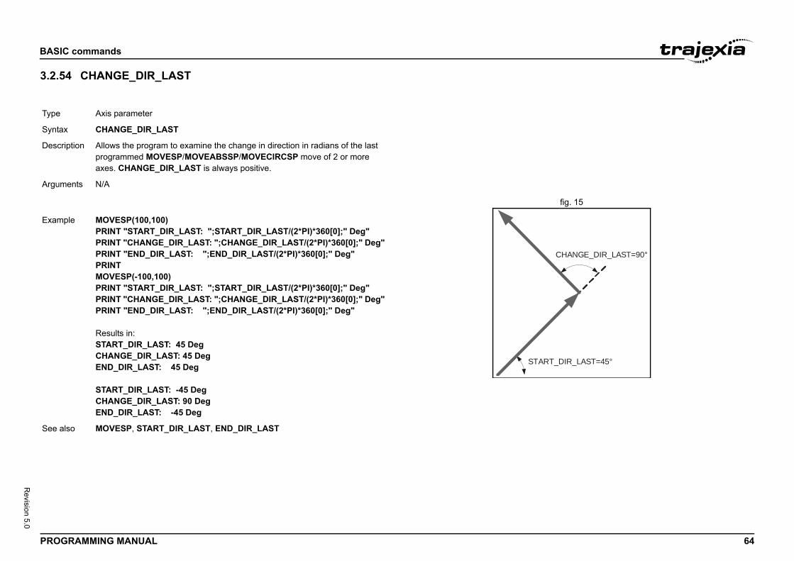
BASIC
PROG 64
Revision 5.0
3.2.5/i
fig. 15/i
Type
Synta
Descr
Argum
CHANGE_DIR_LAST=90°
ART_DIR_LAST=45°
Exam
See a
commands
RAMMING MANUAL
4 CHANGE_DIR_LAST
Axis parameter
x CHANGE_DIR_LAST
iption Allows the program to examine the change in direction in radians of the last programmed MOVESP/MOVEABSSP/MOVECIRCSP move of 2 or more axes. CHANGE_DIR_LAST is always positive.
ents N/A
ST
ple MOVESP(100,100)PRINT "START_DIR_LAST: ";START_DIR_LAST/(2*PI)*360[0];" Deg"PRINT "CHANGE_DIR_LAST: ";CHANGE_DIR_LAST/(2*PI)*360[0];" Deg"PRINT "END_DIR_LAST: ";END_DIR_LAST/(2*PI)*360[0];" Deg"PRINTMOVESP(-100,100)PRINT "START_DIR_LAST: ";START_DIR_LAST/(2*PI)*360[0];" Deg"PRINT "CHANGE_DIR_LAST: ";CHANGE_DIR_LAST/(2*PI)*360[0];" Deg"PRINT "END_DIR_LAST: ";END_DIR_LAST/(2*PI)*360[0];" Deg"
Results in:START_DIR_LAST: 45 DegCHANGE_DIR_LAST: 45 DegEND_DIR_LAST: 45 Deg
START_DIR_LAST: -45 DegCHANGE_DIR_LAST: 90 DegEND_DIR_LAST: -45 Deg
lso MOVESP, START_DIR_LAST, END_DIR_LAST
BASIC
PROG 65
Revision 5.0
3.2.5/i
3.2.5/i
3.2.5/i
Type
Synta
Descr
Argum
Exam
See a
Type
Synta
Descr
Argum
Exam
See a
Type
Synta
nd resets all global VR variables to 0 and sets local varia-on which the command is run to 0. When you use it in a local variables defined to 0.
)=44.3158: VR(300)=-12(20), VR(300)2.0000
(20), VR(300)00
mber, vr_number)
mmand resets the specified bit in the specified VR varia- variable keep their values.
he bit to be reset. Range: 0 - 52.
he VR variable for which the bit will be reset. 9.
)
T, VR.
commands
RAMMING MANUAL
5 CHECKSUM
6 CHR
7 CLEAR
3.2.58 CLEAR_BIT/i
System parameter (read-only)
x CHECKSUM
iption The CHECKSUM parameter contains the checksum for the programs in RAM. At start-up, the checksum is recalculated and compared with the previously held value. If the checksum is incorrect the program will not run.
ents N/A
ple No example.
lso N/A
I/O command
x CHR(x)
iption The CHR command is used to send individual ASCII characters which are referred to by number. PRINT CHR(x); is equivalent to PUT(x) in some other versions of BASIC.
ents • xA BASIC expression.
ple >>PRINT CHR(65);A
lso N/A
System command
x CLEAR
Description The CLEAR commables on the process program it resets all
Arguments N/A
Example >>VR(0)=22: VR(20>>PRINT VR(0), VR22.0000 44.3158 -1>>CLEAR>>PRINT VR(0), VR0.0000 0.0000 0.00
See also RESET, VR
Type System command
Syntax CLEAR_BIT(bit_nu
Description The CLEAR_BIT coble. Other bits in the
Arguments • bit_numberThe number of t
• vr_numberThe number of tRange: 0 - 6399
Example >>PRINT VR(17)112.0000>>CLEAR_BIT(5, 17>>PRINT VR(17)80.0000
See also READ_BIT, SET_BI
BASIC
PROG 66
Revision 5.0
3.2.5/i
3.2.6/i
Type
Synta
Descr
Argum
Exam
See a
Type
Synta
Descr
Argum
Exam
See a
axis parameter defines the change in connection ratio NECT command. The rate is defined as amount of ratio
using CLUTCH_RATE is not deterministic in position. If VELINK command instead to avoid unnecessary phase ase axis and linked axis.
y that when giving CONNECT(4,1), it will take one sec-connection.
OVELINK.
ber, address, index, subindex ,type [,output])
CANopen object from an EtherCAT device. Upon suc-is command returns -1 and puts the read value in the VR cified or prints it to the current output device. If the com-cuted, the value 0 is returned.
waits for the response of the device so, its execution is e variable. Do not use this command together with other
require quick execution.nly perform CO_READ(_AXIS) and CO_WRITE(_AXIS) s to prevent interference during execution.
commands
RAMMING MANUAL
9 CLEAR_PARAMS
0 CLOSE_WIN
3.2.61 CLUTCH_RATE/i
3.2.62 CO_READ/i
System command
x CLEAR_PARAMS
iption Clears all variables and parameters stored in Flash-ROM to their default val-ues. The CLEAR_PARAMS command will erase (set to 0) all the VR’s stored using FLASHVR command. This command cannot be performed if the con-troller is locked.
ents N/A
ple No example.
lso FLASHVR
Axis parameter
x CLOSE_WINCW
iption The CLOSE_WIN axis parameter defines the end of the window inside or out-side which a registration mark is expected. The value is in user units.Note: OPEN_WIN must be the numerically smaller than CLOSE_WIN
ents N/A
ple OPEN_WIN=1000CLOSE_WIN=2000
lso AXIS, OPEN_WIN, REGIST, UNIT_INIT.
Type Axis parameter
Syntax CLUTCH_RATE
Description The CLUTCH_RATEwhen using the CONper second.Note: The operation required, use the MOdifference between b
Arguments N/A
Example CLUTCH_RATE = 4This setting will implond to reach the full
See also AXIS, CONNECT, M
Type System command
Syntax CO_READ(unit_num
Description Command to read a cessful execution, thmemory location spemand cannot be exeNotes:• This command
slow and the timcommands that
• It is advised to ofrom one proces
BASIC
PROG 67
Revision 5.0
Argum
Exam
See a
is, index, subindex ,type [,output])
CANopen object from an EtherCAT axis. Upon success-mmand returns -1 and puts the read value in the VR cified or prints it to the current output device. If the com-cuted, the value 0 is returned.
waits for the response of the device so, its execution is e variable. Do not use this command together with other
require quick execution.nly perform CO_READ(_AXIS) and CO_WRITE(_AXIS) s to prevent interference during execution.
commands
RAMMING MANUAL
3.2.63 CO_READ_AXIS/i
ents • unit_numberUnit number of the EtherCAT master to which the slave is attached.
• addressConfigured address of the EtherCAT slave
• indexIndex number of the CANopen object
• subindexSub-index number of the CANopen object
• typeData-type of the CANopen object1 Boolean (BOOL)2 Integer8 (INT8)3 Integer16 (INT16)4 Integer32 (INT32)5 Unsigned8 (U8)6 Unsigned16 (U16)7 Unsigned32 (U32)9 Visible string (VS)
• outputPointer to VR array to read data into or -1 if data to be returned to the cur-rent output device. Default -1.
In case of reading a Visible String (type = 9), an additional (length) parameter is required:CO_READ(unit_number, address, index, subindex ,type, length [,output])
• lengthNumber of characters to read from the CANopen object
ple Read StatusWord (object 6040h) of a G5-ECT drive at address 2 and put the result in VR(100):CO_READ(0,2,$6040,0,6,100)
lso CO_READ_AXIS, CO_WRITE
Type System command
Syntax CO_READ_AXIS(ax
Description Command to read a ful execution, this comemory location spemand cannot be exeNotes:• This command
slow and the timcommands that
• It is advised to ofrom one proces
BASIC
PROG 68
Revision 5.0
3.2.6/i
Argum
Exam
See a
Type
Synta
CANopen object of an EtherCAT device. Upon success-mmand returns -1. If the command cannot be executed, d.
waits for the response of the device so, its execution is e variable. Do not use this command together with other
require quick execution.nly perform CO_READ(_AXIS) and CO_WRITE(_AXIS) s to prevent interference during execution.
the EtherCAT master to which the slave is attached.
ress of the EtherCAT slave
f the CANopen object
er of the CANopen object
CANopen objectOL)8)T16)T32)8)
(U16)(U32)
the start of the VR block where the data will be fetched
s that the value is in the next parameter [Value]
written to the CANopen object.
ITE_AXIS
commands
RAMMING MANUAL
4 CO_WRITE
ents • axisAxis number of the EtherCAT drive.
• indexIndex number of the CANopen object
• subindexSub-index number of the CANopen object
• typeData-type of the CANopen object1 Boolean (BOOL)2 Integer8 (INT8)3 Integer16 (INT16)4 Integer32 (INT32)5 Unsigned8 (U8)6 Unsigned16 (U16)7 Unsigned32 (U32)9 Visible string (VS)
• outputPointer to VR array to read data into or -1 if data to be returned to the cur-rent output device. Default -1.
In case of reading a Visible String (type = 9), an additional (length) parameter is required:CO_READ_AXIS(axis, index, subindex ,type, length [,output])
• lengthNumber of characters to read from the CANopen object
ple Read StatusWord (object 6040h) of a G5-ECT drive at axis 2 and put the result in VR(100):CO_READ(2,$6040,0,6,100)
lso CO_READ, CO_WRITE_AXIS
System command
x CO_WRITE(unit_number, address, index, subindex ,type, data [,value])
Description Command to write aful execution, this cothe value 0 is returneNotes:• This command
slow and the timcommands that
• It is advised to ofrom one proces
Arguments • unit_numberUnit number of
• addressConfigured add
• indexIndex number o
• subindexSub-index numb
• typeData-type of the1 Boolean (BO2 Integer8 (INT3 Integer16 (IN4 Integer32 (IN5 Unsigned8 (U6 Unsigned16 7 Unsigned32
• data0 to n specifies fromData: -1 specifie
• valueThe value to be
Example N/A
See also CO_READ, CO_WR
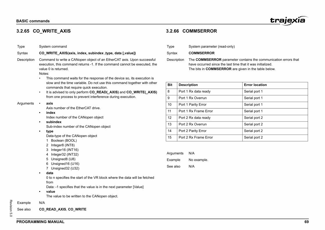
BASIC
PROG 69
Revision 5.0
3.2.6/i
Type
Synta
Descr
Argum
Exam
See a
ead-only)
parameter contains the communication errors that the last time that it was initialized.RROR are given in the table below.
Error location
Serial port 1
Serial port 1
Serial port 1
Serial port 1
Serial port 2
Serial port 2
Serial port 2
Serial port 2
commands
RAMMING MANUAL
5 CO_WRITE_AXIS 3.2.66 COMMSERROR/i
/i
/i
System command
x CO_WRITE_AXIS(axis, index, subindex ,type, data [,value])
iption Command to write a CANopen object of an EtherCAT axis. Upon successful execution, this command returns -1. If the command cannot be executed, the value 0 is returned.Notes:• This command waits for the response of the device so, its execution is
slow and the time variable. Do not use this command together with other commands that require quick execution.
• It is advised to only perform CO_READ(_AXIS) and CO_WRITE(_AXIS) from one process to prevent interference during execution.
ents • axisAxis number of the EtherCAT drive.
• indexIndex number of the CANopen object
• subindexSub-index number of the CANopen object
• typeData-type of the CANopen object1 Boolean (BOOL)2 Integer8 (INT8)3 Integer16 (INT16)4 Integer32 (INT32)5 Unsigned8 (U8)6 Unsigned16 (U16)7 Unsigned32 (U32)
• data0 to n specifies the start of the VR block where the data will be fetched fromData: -1 specifies that the value is in the next parameter [Value]
• valueThe value to be written to the CANopen object.
ple N/A
lso CO_READ_AXIS, CO_WRITE
Type System parameter (r
Syntax COMMSERROR
Description The COMMSERRORhave occurred sinceThe bits in COMMSE
Bit Description
8 Port 1 Rx data ready
9 Port 1 Rx Overrun
10 Port 1 Parity Error
11 Port 1 Rx Frame Error
12 Port 2 Rx data ready
13 Port 2 Rx Overrun
14 Port 2 Parity Error
15 Port 2 Rx Frame Error
Arguments N/A
Example No example.
See also N/A
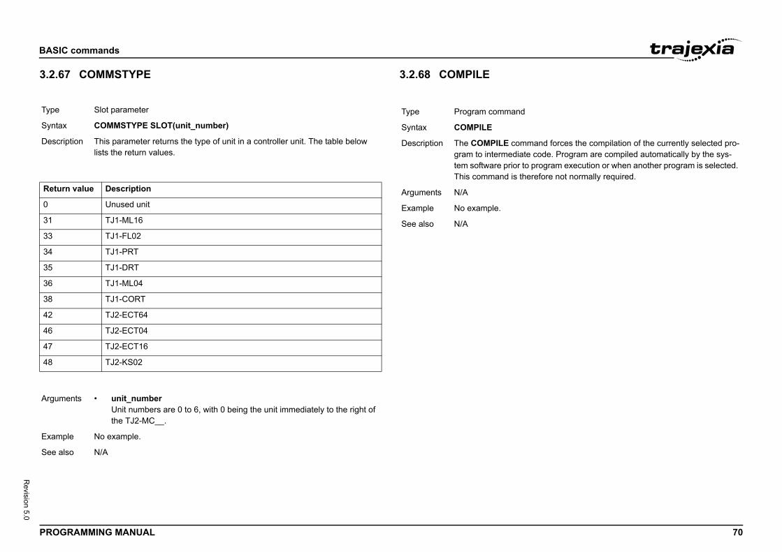
BASIC
PROG 70
Revision 5.0
3.2.6/i
/i
/i
Type
Synta
Descr
Retur
0
31
33
34
35
36
38
42
46
47
48
Argum
Exam
See a
and forces the compilation of the currently selected pro- code. Program are compiled automatically by the sys- program execution or when another program is selected. refore not normally required.
commands
RAMMING MANUAL
7 COMMSTYPE 3.2.68 COMPILE/i
Slot parameter
x COMMSTYPE SLOT(unit_number)
iption This parameter returns the type of unit in a controller unit. The table below lists the return values.
n value Description
Unused unit
TJ1-ML16
TJ1-FL02
TJ1-PRT
TJ1-DRT
TJ1-ML04
TJ1-CORT
TJ2-ECT64
TJ2-ECT04
TJ2-ECT16
TJ2-KS02
ents • unit_numberUnit numbers are 0 to 6, with 0 being the unit immediately to the right of the TJ2-MC__.
ple No example.
lso N/A
Type Program command
Syntax COMPILE
Description The COMPILE commgram to intermediatetem software prior toThis command is the
Arguments N/A
Example No example.
See also N/A
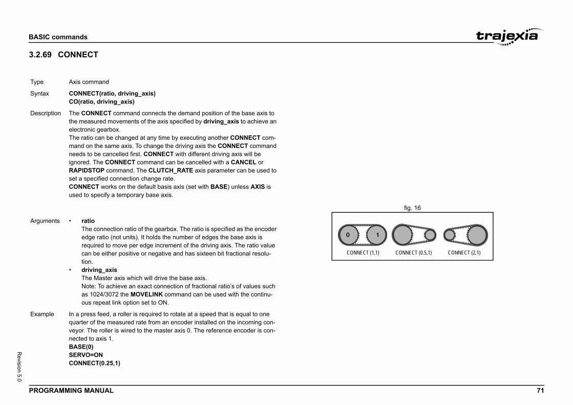
BASIC
PROG 71
Revision 5.0
3.2.6/i
fig. 16/i
Type
Synta
Descr
CONNECT (0.5,1) CONNECT (2,1)
Argum
Exam
commands
RAMMING MANUAL
9 CONNECT
Axis command
x CONNECT(ratio, driving_axis)CO(ratio, driving_axis)
iption The CONNECT command connects the demand position of the base axis to the measured movements of the axis specified by driving_axis to achieve an electronic gearbox.The ratio can be changed at any time by executing another CONNECT com-mand on the same axis. To change the driving axis the CONNECT command needs to be cancelled first. CONNECT with different driving axis will be ignored. The CONNECT command can be cancelled with a CANCEL or RAPIDSTOP command. The CLUTCH_RATE axis parameter can be used to set a specified connection change rate.CONNECT works on the default basis axis (set with BASE) unless AXIS is used to specify a temporary base axis.
CONNECT (1,1)
ents • ratioThe connection ratio of the gearbox. The ratio is specified as the encoder edge ratio (not units). It holds the number of edges the base axis is required to move per edge increment of the driving axis. The ratio value can be either positive or negative and has sixteen bit fractional resolu-tion.
• driving_axisThe Master axis which will drive the base axis.Note: To achieve an exact connection of fractional ratio’s of values such as 1024/3072 the MOVELINK command can be used with the continu-ous repeat link option set to ON.
ple In a press feed, a roller is required to rotate at a speed that is equal to one quarter of the measured rate from an encoder installed on the incoming con-veyor. The roller is wired to the master axis 0. The reference encoder is con-nected to axis 1.BASE(0)SERVO=ONCONNECT(0.25,1)
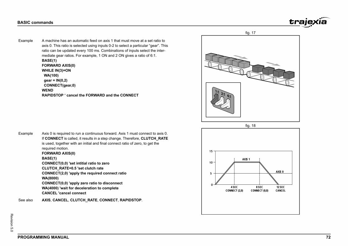
BASIC
PROG 72
Revision 5.0
fig. 17/i
fig. 18/i
Exam
AXIS 1
AXIS 0
CT (2,0)
8 SECCONNECT (0,0)
12 SECCANCEL
Exam
See a
commands
RAMMING MANUAL
ple A machine has an automatic feed on axis 1 that must move at a set ratio to axis 0. This ratio is selected using inputs 0-2 to select a particular “gear”. This ratio can be updated every 100 ms. Combinations of inputs select the inter-mediate gear ratios. For example, 1 ON and 2 ON gives a ratio of 6:1.BASE(1)FORWARD AXIS(0)WHILE IN(3)=ON WA(100) gear = IN(0,2) CONNECT(gear,0)WENDRAPIDSTOP ‘ cancel the FORWARD and the CONNECT
4 SECONNEC
ple Axis 0 is required to run a continuous forward. Axis 1 must connect to axis 0. If CONNECT is called, it results in a step change. Therefore, CLUTCH_RATE is used, together with an initial and final connect ratio of zero, to get the required motion.FORWARD AXIS(0)BASE(1)CONNECT(0,0) 'set intitial ratio to zeroCLUTCH_RATE=0.5 'set clutch rateCONNECT(2,0) 'apply the required connect ratioWA(8000)CONNECT(0,0) 'apply zero ratio to disconnectWA(4000) 'wait for deceleration to completeCANCEL 'cancel connect
lso AXIS, CANCEL, CLUTCH_RATE, CONNECT, RAPIDSTOP.
BASIC
PROG 73
Revision 5.0
3.2.7/i
Type
Synta
Descr
Argum
Exam
See a
ead-only)
meter returns the type of TJ2-MC__ in the system.4462hine Controller is locked, 1000 is added to above values, -MC64 will return 1266.
me new_program_name
d copies an existing program in the controller to a new cified name. The program name can be specified without
is implemented for the Command Line Terminal.
gram to be copied.name the new program.
ewprog"
E.
commands
RAMMING MANUAL
0 CONSTANT 3.2.71 CONTROL/i
3.2.72 COPY/i
System command
x CONSTANT ["name"[, value]]
iption Declares the name as a constant for use both within the program containing the CONSTANT definition and all other programs in the Trajexia Studio pro-ject.
Note: The program containing the CONSTANT definition must be run before the name is used in other programs. In addition, only that program should be running at the time the CONSTANT is executed, otherwise the program error will appear and the program will stop when trying to execute this command. For fast startup the program should also be the only process running at power-up.Using CONSTANT with only the name will erase the specified constant.Using CONSTANT with no parameters will erase all CONSTANT declara-tions. This also happens when the TJ2-MC__ is reset by switching the power off and back on, or by executing the EX command.A maximum of 1024 CONSTANTs can be declared.The maximum length of the name of the GLOBAL is 32 characters.
ents • nameAny user-defined name containing lower case alpha, numerical or under-score characters.
• valueThe value assigned to name.
ple CONSTANT "nak", $15CONSTANT "start_button", 5IF IN(start_button)=ON THEN OP(led1, ON)IF key_char=nak THEN GOSUB no_ack_received
lso LIST_GLOBAL
Type System parameter (r
Syntax CONTROL
Description The CONTROL para• 266 = TJ2-MC6• 267 = TJ2-MC0• 268 = TJ2-MC1• 269 = TJ2-MC0Note: When the Macso e.g. a locked TJ2
Arguments N/A
Example No example.
See also N/A
Type Program command
Syntax COPY program_na
Description The COPY commanprogram with the spequotes.Note: This command
Arguments • program_nameName of the pro
• new_program_Name to use for
Example >> COPY "prog" "n
See also DEL, NEW, RENAM
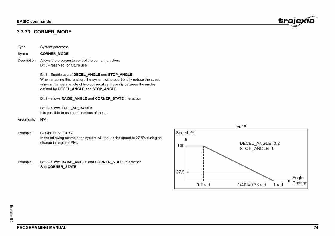
BASIC
PROG 74
Revision 5.0
3.2.7/i
fig. 19/i
/i
Type
Synta
Descr
Argum
1/4PI=0.78 rad 1 radAngleChange
DECEL_ANGLE=0.2STOP_ANGLE=1
Exam
Exam
commands
RAMMING MANUAL
3 CORNER_MODE
System parameter
x CORNER_MODE
iption Allows the program to control the cornering action:Bit 0 - reserved for future use
Bit 1 - Enable use of DECEL_ANGLE and STOP_ANGLEWhen enabling this function, the system will proportionally reduce the speed when a change in angle of two consecutive moves is between the angles defined by DECEL_ANGLE and STOP_ANGLE.
Bit 2 - allows RAISE_ANGLE and CORNER_STATE interaction
Bit 3 - allows FULL_SP_RADIUSIt is possible to use combinations of these.
ents N/A
100
27.5
0.2 rad
Speed [%]ple CORNER_MODE=2In the following example the system will reduce the speed to 27.5% during an change in angle of PI/4.
ple Bit 2 - allows RAISE_ANGLE and CORNER_STATE interactionSee CORNER_STATE
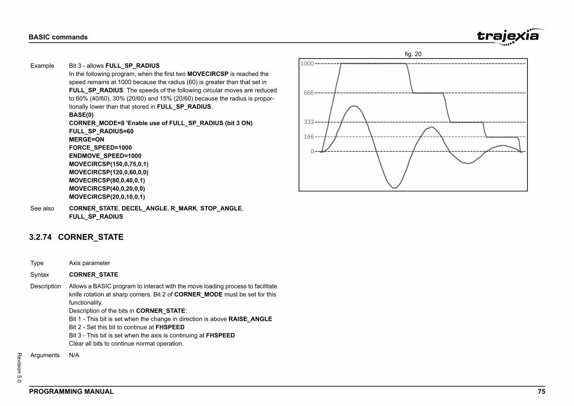
BASIC
PROG 75
Revision 5.0
fig. 20/i
3.2.7/i
Exam
See a
Type
Synta
Descr
Argum
commands
RAMMING MANUAL
4 CORNER_STATE
0
1000
666
333
166
ple Bit 3 - allows FULL_SP_RADIUSIn the following program, when the first two MOVECIRCSP is reached the speed remains at 1000 because the radius (60) is greater than that set in FULL_SP_RADIUS. The speeds of the following circular moves are reduced to 60% (40/60), 30% (20/60) and 15% (20/60) because the radius is propor-tionally lower than that stored in FULL_SP_RADIUS.BASE(0)CORNER_MODE=8 'Enable use of FULL_SP_RADIUS (bit 3 ON)FULL_SP_RADIUS=60MERGE=ONFORCE_SPEED=1000ENDMOVE_SPEED=1000MOVECIRCSP(150,0,75,0,1)MOVECIRCSP(120,0,60,0,0)MOVECIRCSP(80,0,40,0,1)MOVECIRCSP(40,0,20,0,0)MOVECIRCSP(20,0,10,0,1)
lso CORNER_STATE, DECEL_ANGLE, R_MARK, STOP_ANGLE, FULL_SP_RADIUS
Axis parameter
x CORNER_STATE
iption Allows a BASIC program to interact with the move loading process to facilitate knife rotation at sharp corners. Bit 2 of CORNER_MODE must be set for this functionality.Description of the bits in CORNER_STATE:Bit 1 - This bit is set when the change in direction is above RAISE_ANGLEBit 2 - Set this bit to continue at FHSPEEDBit 3 - This bit is set when the axis is continuing at FHSPEEDClear all bits to continue normal operation.
ents N/A
BASIC
PROG 76
Revision 5.0
3.2.7/i
3.2.7/i
Exam
See a
Type
Synta
Descr
Argum
Exam
See a
Type
Synta
Descr
de of the command.e command with the Polynomial CRC. Will return 0 if Initialise has not been run
as seed for CRC check range 0-65535 (or 0-$FFFF)
he data is loadedory
first byte
last byte
e. Normally $0 - $FFFF
ry:
ialise internal CRC table memory,7,8) ‘Load data into table memory location 0-7,0,0,7,reginit) 'Source Data=TABLE(0..7)
ialise internal CRC table memoryR memory location 0-5
,1,0,5,reginit) 'Source Data=VR(0)..VR(5)
commands
RAMMING MANUAL
5 COS
6 CRC16
ple MOVEABSSP(x,y)IF CHANGE_DIR_LAST>RAISE_ANGLE THEN WAIT UNTIL CORNER_STATE>0 GOSUB raise CORNER_STATE=3 WA(10) WAIT UNTIL VP_SPEED AXIS(2)=0 GOSUB lower CORNER_STATE=0ENDIF
lso CORNER_MODE, R_MARK, FHSPEED
Mathematical function
x COS(expression)
iption The COS function returns the cosine of the expression. Input values are in radians and may have any value. The result value will be in the range from -1 to 1.
ents • expressionAny valid BASIC expression.
ple >> PRINT COS(0)1.0000
lso N/A
System command
x mode=0: CRC16(mode, poly)mode=1: CRC16(mode, data_source, start, end, reg)
iption Calculates the 16 bit CRC of data stored in contiguous Table Memory or VR Memory locations.
Arguments • modeSpecifies the mo0 = Initialises th1 = Returns the
• polyPolynomial used
• data_sourceDefines where t0 = TABLE mem1 = VR memory
• startStart location of
• endEnd location of
• regInitial CRC valu
Example Using TABLE memopoly = $90d9reginit = $ffffCRC16(0, poly) 'InitTABLE(0,1,2,3,4,5,6calc_crc = CRC16(1
Example Using VR memory:poly = $90d9reginit = $ffffCRC16(0, poly) 'Init‘Load 6 bytes into VFOR i=0 TO 5 VR(i)=i+1NEXT icalc_crc = CRC16(1
See also N/A
BASIC
PROG 77
Revision 5.0
3.2.7/i
3.2.7/i
Type
Synta
Descr
Argum
Exam
See a
Type
Synta
Descr
Argum
AIN, P_GAIN, VFF_GAIN.
e
s in conjunction with D_ZONE_MIN to clamp the DAC the demand movement is complete and the magnitude of s less than the D_ZONE_MIN value. The servo loop will either the Following Error rises above the e, or a fresh movement is started.
ters set as above, the DAC output will be clamped at ment is complete and the Following Error falls below 3. restarted or if the Following Error rises above a value of
ill be reactivated.
e
s in conjunction with D_ZONE_MAX to clamp the DAC the demand movement is complete and the magnitude of s less than the D_ZONE_MIN value. The servo loop will either the Following Error rises above the e, or a fresh movement is started.
commands
RAMMING MANUAL
7 CREEP
8 D_GAIN
3.2.79 D_ZONE_MAX/i
3.2.80 D_ZONE_MIN/i
Axis parameter
x CREEP
iption The CREEP axis parameter contains the creep speed for the axis. The creep speed is used for the slow part of an origin search sequence. CREEP can have any positive value, including 0.The creep speed is entered in units/sec with the unit conversion factor UNITS. For example, if the unit conversion factor is set to the number of encoder edges/inch, the speed is set in inches/sec.
ents N/A
ple BASE(2)CREEP=10SPEED=500DATUM(4)CREEP AXIS(1)=10SPEED AXIS(1)=500DATUM(4) AXIS(1)
lso AXIS, DATUM, UNIT_INIT.
Axis parameter
x D_GAIN
iption The D_GAIN axis parameter contains the derivative gain for the axis. The derivative output contribution is calculated by multiplying the change in Fol-lowing Error with D_GAIN. The default value is 0.Add the derivative gain to a system to produce a smoother response and to allow the use of a higher proportional gain that could not be used otherwise. High values can cause oscillation.Note: The servo gain must only be changed when the SERVO is off.Note: Servo gains have no affect on stepper output axis, ATYPE=46.
ents N/A
Example D_GAIN=0.25
See also AXIS, I_GAIN, OV_G
Type System parameter
Syntax D_ZONE_MAX=valu
Description This parameter workoutput to zero when the Following Error ibe reactivated whenD_ZONE_MAX valu
Arguments N/A
Example D_ZONE_MIN=3D_ZONE_MAX=10With these 2 paramezero when the moveWhen a movement is10, the servo loop w
See also D_ZONE_MIN.
Type System parameter
Syntax D_ZONE_MIN=valu
Description This parameter workoutput to zero when the Following Error ibe reactivated whenD_ZONE_MAX valu
Arguments N/A
BASIC
PROG 78
Revision 5.0
3.2.8
See S
3.2.8
See S
3.2.8/i
Exam
See a
Type
Synta
Descr
3)=-16
urrent date held by the Trajexia' s real time clock. The red in DD:MM:YY or DD:MM:YYYY format.
er representing the current day. This number is the num-t January 2000, with 1 Jan. 1900 represented as 1.
te DD/MMM/YYYY as a string to the communication port. tion is given.
e in format for example: 20/Oct/2005
commands
RAMMING MANUAL
1 DAC
_REF.
2 DAC_OUT
_REF_OUT.
3 DAC_SCALE
3.2.84 DATE/i
3.2.85 DATE$/i
ple D_ZONE_MIN=3D_ZONE_MAX=10With these 2 parameters set as above, the DAC output will be clamped at zero when the movement is complete and the Following Error falls below 3. When a movement is restarted or if the Following Error rises above a value of 10, the servo loop will be reactivated.
lso D_ZONE_MAX.
Axis parameter
x DAC_SCALE
iption The DAC_SCALE axis parameter is an integer multiplier which is applied between the servo control loop output and the Digital to Analog Converter which output is supplied to the Servo Drive. Its value is set to 16 on axes with a 16 bit Digital to Analog Converter, which are Flex axis types. This scales the values applied to the higher resolution DAC so that the gains required on the axis are similar to those required on the other controllers.DAC_SCALE may be set negative (-16) to reverse the polarity of the DAC output signal. This is useful in case if e.g. absolute SSI encoder used has no capability of changing default CW/CCW rotation direction and the default direction is opposite to the one of the Servo Drive used.Notes:• When the SERVO is OFF for a given axis, the magnitude of
DAC_SCALE is not important as the voltage applied is controlled by the DAC parameter. The polarity is still reversed however by DAC_SCALE.
• The default DAC_SCALE value for MECHATROLINK-II or EtherCAT axis types is 1.
Arguments N/A
Example DAC_SCALE AXIS(
See also DAC, S_REF.
Type System parameter
Syntax DATE
Description Returns or sets the cnumber may be ente
Arguments N/A
Example DATE=25:09:09orDATE=25:09:2009
Example >>PRINT DATE3555This prints the numbber of days since 1s
See also N/A
Type System command
Syntax DATE$
Description Prints the current daA 4-digit year descrip
Arguments N/A
Example PRINT #1, DATE$This will print the dat
See also N/A
BASIC
PROG 79
Revision 5.0
3.2.8/i
/i
Type
Synta
Descr
Argum
sequvalue
0
eep speed forward until the Z marker is encountered. is then reset to 0 and the measured position corrected Following Error.
eep speed in reverse until the Z marker is encountered. is then reset to 0 and the measured position corrected Following Error.
e demand speed forward until the datum switch is n moves reverse at creep speed until the datum switch position is then reset to 0 and the measured position intain the Following Error.
e demand speed in reverse until the datum switch is n moves forward at creep speed until the datum switch position is then reset to 0 and the measured position intain the Following Error.
mand speed forward until the datum switch is reached. s at creep speed until the datum switch is reset. The rse at creep speed until the Z marker of the encoder is
mand position is then reset to 0 and the measured posi-o maintain the Following Error.
mand speed reverse until the datum switch is reached. forward at creep speed until the datum switch is reset. rward at creep speed until the Z marker of the encoder is mand position is then reset to 0 and the measured posi-o maintain the Following Error.
commands
RAMMING MANUAL
6 DATUM
Axis command
x DATUM(sequence)
iption The DATUM command performs one of 6 origin search sequences to position an axis to an absolute position and also reset the error bits in AXIS_FS_LIMIT axis parameter.DATUM uses both the creep and demand speed for the origin search. The creep speed in the sequences is set with the CREEP axis parameter and the demand speed is set with the SPEED axis parameter. The datum switch input number, used for sequences 3 to 6, is set by the DATUM_IN parameter.DATUM works on the default basis axis (set with BASE) unless AXIS is used to specify a temporary base axis.Note: The origin input set with the DATUM_IN parameter is active low, i.e., the origin switch is set when the input is OFF. The feedhold, reverse jog, forward jog, forward and reverse limit inputs are also active low. Active low inputs are used to enable fail-safe wiring.
ents • sequenceSee the table below.
ence Description
The DATUM(0) command will clear the motion error. The currently measured position is set as the demand position (this is especially useful on stepper axes with position verification). DATUM(0) also clears the Following Error that exceeded the FE_LIMIT condition in the AXISSTATUS register for ALL axes. It sets these bits in AXISSTATUS to zero:Bit 1 : Following Error Warning. Bit 2 : Remote Drive Comms Error. Bit 3 : Remote Drive Error. Bit 8 : Following Error Limit Exceeded. Bit 11 : Cancelling Move. Note that the status can not be cleared if the cause of the problem is still pre-sent. DATUM(0) must only be used after the WDOG is set to OFF, otherwise there will be unpredictable errors on the motion.
1 The axis moves at crThe demand positionso as to maintain the
2 The axis moves at crThe demand positionso as to maintain the
3 The axis moves at threached. The axis theis reset. The demandcorrected so as to ma
4 The axis moves at threached. The axis theis reset. The demandcorrected so as to ma
5 The axis moves at deThe axis then reverseaxis continues in reveencountered. The detion corrected so as t
6 The axis moves at deThe axis then movesThe axis continues foencountered. The detion corrected so as t
sequence value
Description
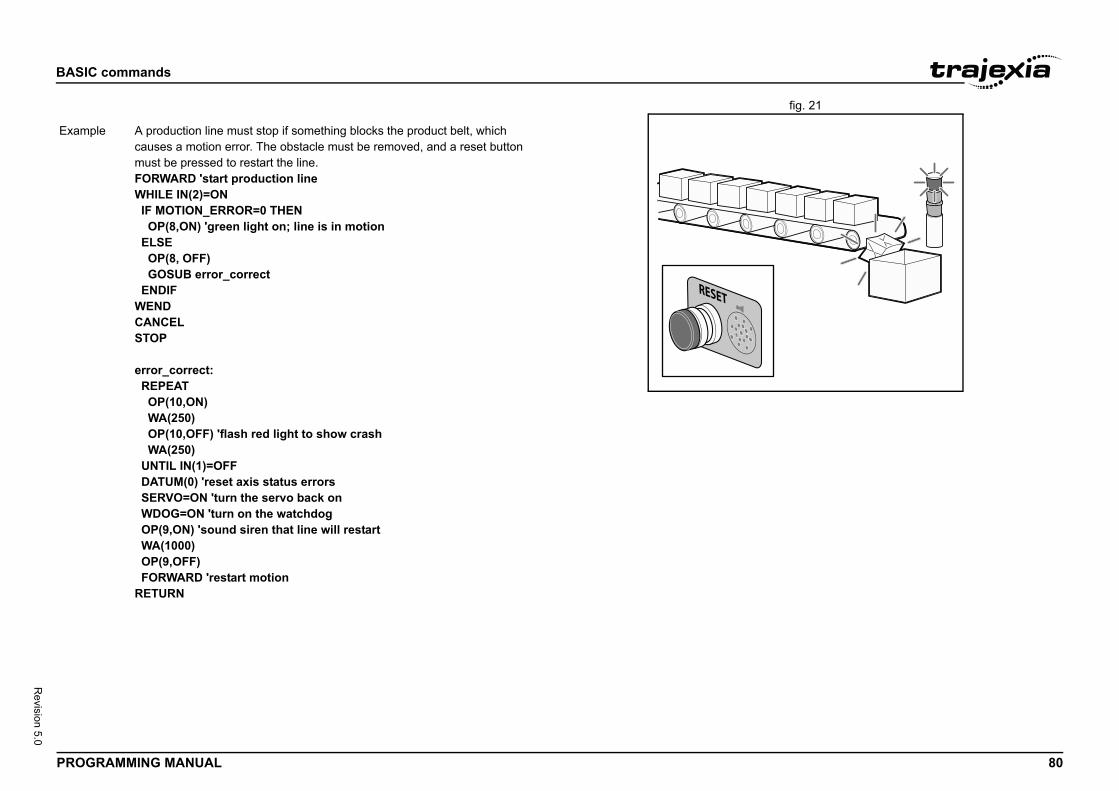
BASIC
PROG 80
Revision 5.0
fig. 21/i
Exam
commands
RAMMING MANUAL
ple A production line must stop if something blocks the product belt, which causes a motion error. The obstacle must be removed, and a reset button must be pressed to restart the line.FORWARD 'start production lineWHILE IN(2)=ON IF MOTION_ERROR=0 THEN OP(8,ON) 'green light on; line is in motion ELSE OP(8, OFF) GOSUB error_correct ENDIFWENDCANCELSTOP
error_correct: REPEAT OP(10,ON) WA(250) OP(10,OFF) 'flash red light to show crash WA(250) UNTIL IN(1)=OFF DATUM(0) 'reset axis status errors SERVO=ON 'turn the servo back on WDOG=ON 'turn on the watchdog OP(9,ON) 'sound siren that line will restart WA(1000) OP(9,OFF) FORWARD 'restart motionRETURN
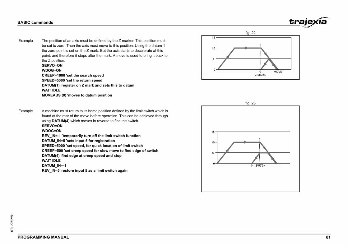
BASIC
PROG 81
Revision 5.0
fig. 22/i
fig. 23/i
Z MARKMOVE
Exam
SWITCH
Exam
commands
RAMMING MANUAL
ple The position of an axis must be defined by the Z marker. This position must be set to zero. Then the axis must move to this position. Using the datum 1 the zero point is set on the Z mark. But the axis starts to decelerate at this point, and therefore it stops after the mark. A move is used to bring it back to the Z position.SERVO=ONWDOG=ONCREEP=1000 'set the search speedSPEED=5000 'set the return speedDATUM(1) 'register on Z mark and sets this to datumWAIT IDLEMOVEABS (0) 'moves to datum position
ple A machine must return to its home position defined by the limit switch which is found at the rear of the move before operation. This can be achieved through using DATUM(4) which moves in reverse to find the switch.SERVO=ONWDOG=ONREV_IN=-1 'temporarily turn off the limit switch functionDATUM_IN=5 'sets input 5 for registrationSPEED=5000 'set speed, for quick location of limit switchCREEP=500 'set creep speed for slow move to find edge of switchDATUM(4) 'find edge at creep speed and stopWAIT IDLEDATUM_IN=-1REV_IN=5 'restore input 5 as a limit switch again
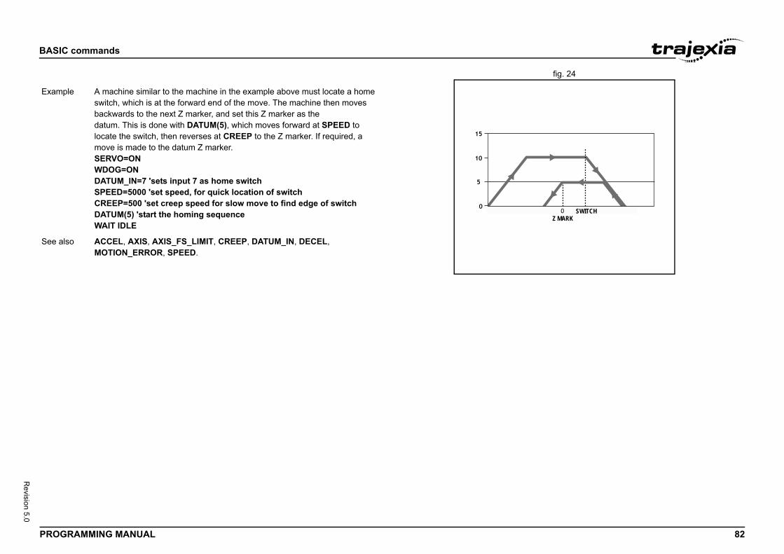
BASIC
PROG 82
Revision 5.0
fig. 24/i
SWITCHZ MARK
Exam
See a
commands
RAMMING MANUAL
ple A machine similar to the machine in the example above must locate a home switch, which is at the forward end of the move. The machine then moves backwards to the next Z marker, and set this Z marker as thedatum. This is done with DATUM(5), which moves forward at SPEED to locate the switch, then reverses at CREEP to the Z marker. If required, a move is made to the datum Z marker.SERVO=ONWDOG=ONDATUM_IN=7 'sets input 7 as home switchSPEED=5000 'set speed, for quick location of switchCREEP=500 'set creep speed for slow move to find edge of switchDATUM(5) 'start the homing sequenceWAIT IDLE
lso ACCEL, AXIS, AXIS_FS_LIMIT, CREEP, DATUM_IN, DECEL, MOTION_ERROR, SPEED.
BASIC
PROG 83
Revision 5.0
3.2.8/i
3.2.8/i
Type
Synta
Descr
Argum
Exam
See a
Type
Synta
Descr
Argum
Exam
See a
y as a string.
ameter contains the axis deceleration rate. The rate is arameter can have any positive value including 0.
eceleration raten rate is ";DECEL;" mm/s/s"
_INIT.
ngle change in radians above which an X-Y system erate. Operation of DECEL_ANGLE applies to forced pends on setting of STOP_ANGLE and
commands
RAMMING MANUAL
7 DATUM_IN
8 DAY
3.2.89 DAY$/i
3.2.90 DECEL/i
3.2.91 DECEL_ANGLE/i
Axis parameter
x DATUM_INDAT_IN
iption The DATUM_IN axis parameter contains the input number to be used as the datum switch input for the DATUM command. The valid input range is given by 0 to 31. Values 0 to 15 represent physically present inputs of TJ2-MC__ I/O connector and are common for all axes.Values 16 to 31 are mapped directly to Drive inputs that are present on the CN1 connector. They are unique for each axis. It depends on the type of Servo Drive which Servo Drive inputs are mapped into inputs 16 to 31.Note: The origin input is active low, i.e., the origin switch is set when the input is OFF. The feedhold, reverse jog, forward jog, forward and reverse limit inputs are also active low. Active low inputs are used to enable fail-safe wir-ing.
ents N/A
ple DATUM_IN AXIS(0)=5
lso AXIS, DATUM.
System parameter (read only)
x DAY
iption Returns the current day as a number 0..6, Sunday is 0.
ents N/A
ple >>? DAY3.0000
lso N/A
Type System command
Syntax DAY$
Description Prints the current da
Arguments N/A
Example >>? DAY$Wednesday
See also N/A
Type Axis parameter
Syntax DECEL
Description The DECEL axis parset in units/s2. The p
Arguments N/A
Example DECEL = 100 ' Set dPRINT " Deceleratio
See also ACCEL, AXIS, UNIT
Type Axis parameter
Syntax DECEL_ANGLE
Description Used to define the ashould start to decelspeed moves and deCORNER_MODE.
BASIC
PROG 84
Revision 5.0
3.2.9/i
Argum
Exam
See a
Type
Synta
Descr
Argum
commands
RAMMING MANUAL
2 DEFPOS
ents N/A
ple ' Decelerate above 15 deg (0.2618 rad)DECEL_ANGLE = 0.2618
lso ACCEL, AXIS, UNIT_INIT.
Axis command
x DEFPOS(pos_1 [ , pos_2 [ , pos_3 [ , pos_4 [, ...]]]])DP(pos_1 [ , pos_2 [ , pos_3 [ , pos_4 [, ...]]]])
iption The DEFPOS command defines the current demand position (DPOS) as a new absolute position. The measured position (MPOS) will be changed accordingly in order to keep the Following Error. DEFPOS is typically used after an origin search sequence (see DATUM command), as this sets the cur-rent position to 0. DEFPOS can be used at any time.As an alternative also the OFFPOS axis parameter can be used. This param-eter can be used to perform a relative adjustment of the current position.DEFPOS works on the default basis axis or axis sequence group (set with BASE) unless AXIS is used to specify a temporary base axis.Note: The changes to the axis position made using DEFPOS or OFFPOS are made on the next servo update. This can potentially cause problems when a move is initiated in the same servo period as the DEFPOS or OFFPOS.The following example shows how the OFFPOS parameter can be used to avoid this problem. DEFPOS commands are internally converted into OFFPOS position offsets, which provides an easy way to avoid the problem by programming as follows:DEFPOS(100): WAIT UNTIL OFFPOS = 0: MOVEABS(0)
ents The command can take up to 64 arguments.• pos_i
The absolute position for (base+i) axis in user units. Refer to the BASE command for the grouping of the axes.
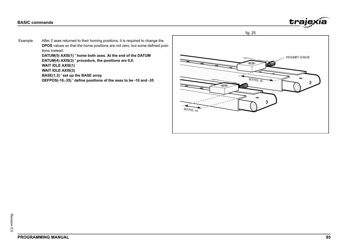
BASIC
PROG 85
Revision 5.0
fig. 25/i
PROXIMITY SENSOR
DEFPOS -35
Exam
commands
RAMMING MANUAL
DEFPOS -10
ple After 2 axes returned to their homing positions, it is required to change the DPOS values so that the home positions are not zero, but some defined posi-tions instead.DATUM(5) AXIS(1) ' home both axes. At the end of the DATUMDATUM(4) AXIS(3) ' procedure, the positions are 0,0.WAIT IDLE AXIS(1)WAIT IDLE AXIS(3)BASE(1,3) ' set up the BASE arrayDEFPOS(-10,-35) ' define positions of the axes to be -10 and -35
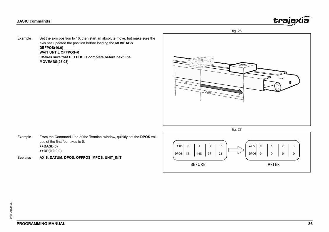
BASIC
PROG 86
Revision 5.0
fig. 26/i
fig. 27/i
Exam
AFTER
Exam
See a
commands
RAMMING MANUAL
ple Set the axis position to 10, then start an absolute move, but make sure theaxis has updated the position before loading the MOVEABS.DEFPOS(10.0)WAIT UNTIL OFFPOS=0' Makes sure that DEFPOS is complete before next lineMOVEABS(25.03)
BEFORE
ple From the Command Line of the Terminal window, quickly set the DPOS val-ues of the first four axes to 0.>>BASE(0)>>DP(0,0,0,0)
lso AXIS, DATUM, DPOS, OFFPOS, MPOS, UNIT_INIT.
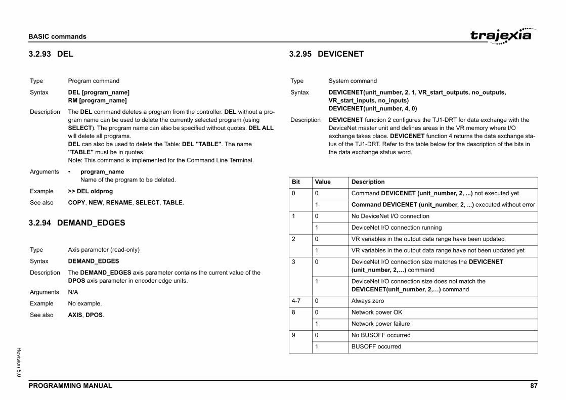
BASIC
PROG 87
Revision 5.0
3.2.9/i
3.2.9/i
Type
Synta
Descr
Argum
Exam
See a
Type
Synta
Descr
Argum
Exam
See a
umber, 2, 1, VR_start_outputs, no_outputs, _inputs)
umber, 4, 0)
n 2 configures the TJ1-DRT for data exchange with the it and defines areas in the VR memory where I/O e. DEVICENET function 4 returns the data exchange sta-Refer to the table below for the description of the bits in tatus word.
EVICENET (unit_number, 2, ...) not executed yet
DEVICENET (unit_number, 2, ...) executed without error
et I/O connection
/O connection running
s in the output data range have been updated
s in the output data range have not been updated yet
/O connection size matches the DEVICENET er, 2,…) command
/O connection size does not match the T(unit_number, 2,…) command
wer OK
wer failure
occurred
curred
commands
RAMMING MANUAL
3 DEL
4 DEMAND_EDGES
3.2.95 DEVICENET/i
/i
Program command
x DEL [program_name]RM [program_name]
iption The DEL command deletes a program from the controller. DEL without a pro-gram name can be used to delete the currently selected program (using SELECT). The program name can also be specified without quotes. DEL ALL will delete all programs.DEL can also be used to delete the Table: DEL "TABLE". The name "TABLE" must be in quotes.Note: This command is implemented for the Command Line Terminal.
ents • program_nameName of the program to be deleted.
ple >> DEL oldprog
lso COPY, NEW, RENAME, SELECT, TABLE.
Axis parameter (read-only)
x DEMAND_EDGES
iption The DEMAND_EDGES axis parameter contains the current value of the DPOS axis parameter in encoder edge units.
ents N/A
ple No example.
lso AXIS, DPOS.
Type System command
Syntax DEVICENET(unit_nVR_start_inputs, noDEVICENET(unit_n
Description DEVICENET functioDeviceNet master unexchange takes plactus of the TJ1-DRT. the data exchange s
Bit Value Description
0 0 Command D
1 Command
1 0 No DeviceN
1 DeviceNet I
2 0 VR variable
1 VR variable
3 0 DeviceNet I(unit_numb
1 DeviceNet IDEVICENE
4-7 0 Always zero
8 0 Network po
1 Network po
9 0 No BUSOFF
1 BUSOFF oc
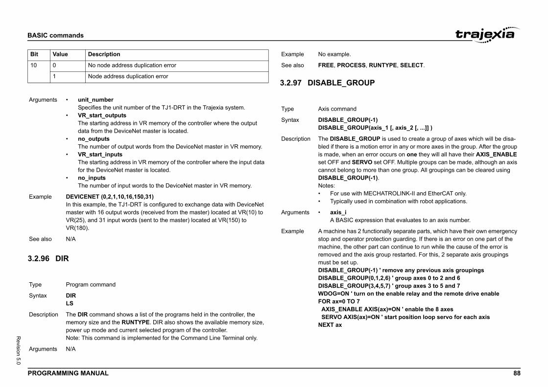
BASIC
PROG 88
Revision 5.0
/i
3.2.9/i
10
Argum
Exam
See a
Type
Synta
Descr
Argum
Bit
UNTYPE, SELECT.
-1)axis_1 [, axis_2 [, ...]] )
UP is used to create a group of axes which will be disa-ion error in any or more axes in the group. After the group ror occurs on one they will all have their AXIS_ENABLE set OFF. Multiple groups can be made, although an axis re than one group. All groupings can be cleared using -1).
CHATROLINK-II and EtherCAT only. combination with robot applications.
sion that evaluates to an axis number.
ctionally separate parts, which have their own emergency otection guarding. If there is an error on one part of the art can continue to run while the cause of the error is s group restarted. For this, 2 separate axis groupings
-1) ' remove any previous axis groupings0,1,2,6) ' group axes 0 to 2 and 63,4,5,7) ' group axes 3 to 5 and 7n the enable relay and the remote drive enable
IS(ax)=ON ' enable the 8 axesON ' start position loop servo for each axis
commands
RAMMING MANUAL
6 DIR
3.2.97 DISABLE_GROUP/i
0 No node address duplication error
1 Node address duplication error
ents • unit_numberSpecifies the unit number of the TJ1-DRT in the Trajexia system.
• VR_start_outputsThe starting address in VR memory of the controller where the output data from the DeviceNet master is located.
• no_outputsThe number of output words from the DeviceNet master in VR memory.
• VR_start_inputsThe starting address in VR memory of the controller where the input data for the DeviceNet master is located.
• no_inputsThe number of input words to the DeviceNet master in VR memory.
ple DEVICENET (0,2,1,10,16,150,31)In this example, the TJ1-DRT is configured to exchange data with DeviceNet master with 16 output words (received from the master) located at VR(10) to VR(25), and 31 input words (sent to the master) located at VR(150) to VR(180).
lso N/A
Program command
x DIRLS
iption The DIR command shows a list of the programs held in the controller, the memory size and the RUNTYPE. DIR also shows the available memory size, power up mode and current selected program of the controller.Note: This command is implemented for the Command Line Terminal only.
ents N/A
Value Description Example No example.
See also FREE, PROCESS, R
Type Axis command
Syntax DISABLE_GROUP(DISABLE_GROUP(
Description The DISABLE_GRObled if there is a motis made, when an erset OFF and SERVOcannot belong to moDISABLE_GROUP(Notes:• For use with ME• Typically used in
Arguments • axis_iA BASIC expres
Example A machine has 2 funstop and operator prmachine, the other premoved and the aximust be set up.DISABLE_GROUP(DISABLE_GROUP(DISABLE_GROUP(WDOG=ON ' turn oFOR ax=0 TO 7 AXIS_ENABLE AX SERVO AXIS(ax)=NEXT ax
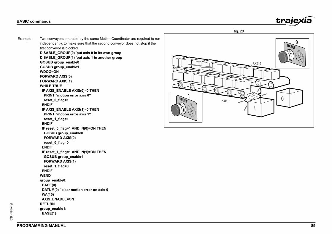
BASIC
PROG 89
Revision 5.0
fig. 28/i
IS 1
AXIS 0
Exam
commands
RAMMING MANUAL
AX
ple Two conveyors operated by the same Motion Coordinator are required to run independently, to make sure that the second conveyor does not stop if the first conveyor is blocked.DISABLE_GROUP(0) 'put axis 0 in its own groupDISABLE_GROUP(1) 'put axis 1 in another groupGOSUB group_enable0GOSUB group_enable1WDOG=ONFORWARD AXIS(0)FORWARD AXIS(1)WHILE TRUE IF AXIS_ENABLE AXIS(0)=0 THEN PRINT "motion error axis 0" reset_0_flag=1 ENDIF IF AXIS_ENABLE AXIS(1)=0 THEN PRINT "motion error axis 1" reset_1_flag=1 ENDIF IF reset_0_flag=1 AND IN(0)=ON THEN GOSUB group_enable0 FORWARD AXIS(0) reset_0_flag=0 ENDIF IF reset_1_flag=1 AND IN(1)=ON THEN GOSUB group_enable1 FORWARD AXIS(1) reset_1_flag=0 ENDIFWENDgroup_enable0: BASE(0) DATUM(0) ' clear motion error on axis 0 WA(10) AXIS_ENABLE=ONRETURNgroup_enable1: BASE(1)
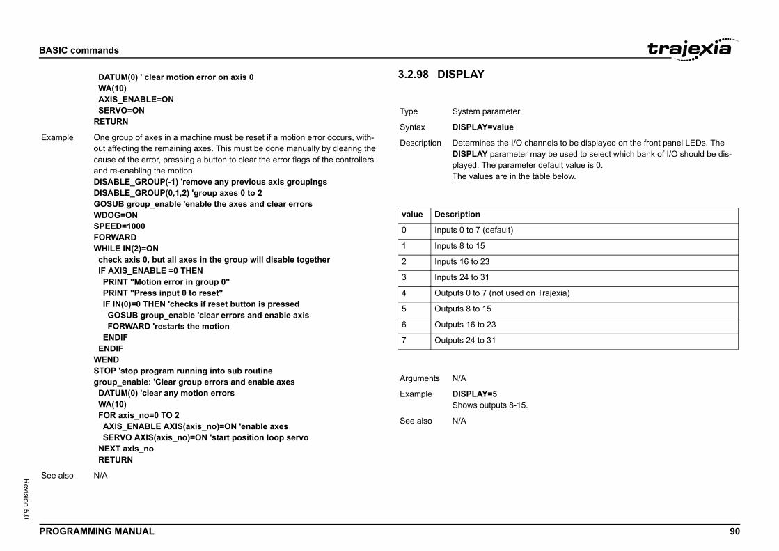
BASIC
PROG 90
Revision 5.0
Exam
See a
hannels to be displayed on the front panel LEDs. The may be used to select which bank of I/O should be dis-ter default value is 0. table below.
on Trajexia)
commands
RAMMING MANUAL
3.2.98 DISPLAY/i
/i
/i
DATUM(0) ' clear motion error on axis 0 WA(10) AXIS_ENABLE=ON SERVO=ONRETURN
ple One group of axes in a machine must be reset if a motion error occurs, with-out affecting the remaining axes. This must be done manually by clearing the cause of the error, pressing a button to clear the error flags of the controllers and re-enabling the motion.DISABLE_GROUP(-1) 'remove any previous axis groupingsDISABLE_GROUP(0,1,2) 'group axes 0 to 2GOSUB group_enable 'enable the axes and clear errorsWDOG=ONSPEED=1000FORWARDWHILE IN(2)=ON check axis 0, but all axes in the group will disable together IF AXIS_ENABLE =0 THEN PRINT "Motion error in group 0" PRINT "Press input 0 to reset" IF IN(0)=0 THEN 'checks if reset button is pressed GOSUB group_enable 'clear errors and enable axis FORWARD 'restarts the motion ENDIF ENDIFWENDSTOP 'stop program running into sub routinegroup_enable: 'Clear group errors and enable axes DATUM(0) 'clear any motion errors WA(10) FOR axis_no=0 TO 2 AXIS_ENABLE AXIS(axis_no)=ON 'enable axes SERVO AXIS(axis_no)=ON 'start position loop servo NEXT axis_no RETURN
lso N/A
Type System parameter
Syntax DISPLAY=value
Description Determines the I/O cDISPLAY parameterplayed. The parameThe values are in the
value Description
0 Inputs 0 to 7 (default)
1 Inputs 8 to 15
2 Inputs 16 to 23
3 Inputs 24 to 31
4 Outputs 0 to 7 (not used
5 Outputs 8 to 15
6 Outputs 16 to 23
7 Outputs 24 to 31
Arguments N/A
Example DISPLAY=5Shows outputs 8-15.
See also N/A
BASIC
PROG 91
Revision 5.0
3.2.9/i
3.2.1/i
Type
Synta
Descr
Argum
Exam
See a
Type
Synta
function reads the current alarm of the Servo Drive that rajexia system via MECHATROLINK-II, EtherCAT or cessful execution, the command returns -1 and stores emory location specified by the VR parameter. If the
executed, the value 0 is returned. The command is exe-r the base axis set by BASE. The base axis can be IS modifier, as with all the other axis commands and
upplied, the alarm history is read with index pointing to ry. For MECHATROLINK-II the active alarms are being and TJ2-KS02 the past alarms are being read.
aits for the response of the axis so, its execution is slow iable. Do not use this command together with other com-ire quick execution.LARM to read the history is not possible when registra-
order to give priority to registration. This is applicable g via the MECHATROLINK-II network or via the
is stored on the VR address on successful execution.
in the alarm history, 0 being the most recent.
RM(10) AXIS(2) THENeadalarm for Servo Drive"
Nve healthy"
rm code: "; VR(10)
an alarm of the Servo Drive driving axis 2 and present e user.
commands
RAMMING MANUAL
9 DPOS
00 DRIVE_ALARM
Axis parameter (read-only)
x DPOS
iption The DPOS axis parameter contains the demand position in user units, which is generated by the move commands in servo control. When the controller is in open loop (SERVO=OFF), the measured position (MPOS) will be copied to the DPOS in order to maintain a 0 Following Error.The range of the demand position is controlled with the REP_DIST and REP_OPTION axis parameters. The value can be adjusted without doing a move by using the DEFPOS command or OFFPOS axis parameter. DPOS is reset to 0 at start-up or controller reset.
ents N/A
ple >> PRINT DPOS AXIS(0)34.0000The above line will return the demand position in user units.
lso AXIS, DPOS, DEFPOS, DEMAND_EDGES, FE, MPOS, REP_DIST, REP_OPTION, OFFPOS, UNIT_INIT.
Axis command
x DRIVE_ALARM(VR [, index])
Description The DRIVE_ALARMis connected to the TTJ2-KS02. Upon sucthe value in the VR mcommand cannot becuted on the Drive fochanged with the AXparameters.When the index is sthe entry in the historead. For EtherCAT Notes:• This command w
and the time varmands that requ
• Using DRIVE_Ation is active in when connectinTJ2-KS02.
Arguments • VRThe alarm value
• indexPosition to read
Example IF NOT DRIVE_ALA PRINT "Failed to rELSE IF VR(10) = 0 THE PRINT "ServoDri ELSE PRINT "Servoala ENDIFENDIFThis example reads that information to th
See also N/A
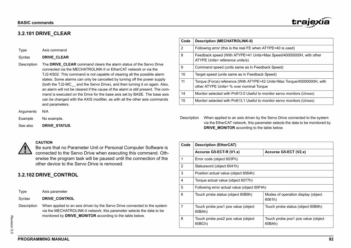
BASIC
PROG 92
Revision 5.0
3.2.1/i
3.2.1/i
Type
Synta
Descr
Argum
Exam
See a
Type
Synta
Descr
LINK-II)
real FE when ATYPE=40 is used)
YPE=41 Units=Max Speed/40000000H, with other nits/s)
me as in Feedback Speed)
as in Feedback Speed)
(With ATYPE=42 Units=Max Torque/40000000H, with er nominal Torque
13.0 Useful to monitor servo monitors (Unxxx)
13.1 Useful to monitor servo monitors (Unxxx)
axis driven by the Servo Drive connected to the system twork, this parameter selects the data to be monitored by ccording to the table below.
) Accurax G5-ECT (V2.x)
)
ct 6064h)
t 6077h)
e (object 60F4h)
t 60B9h) Modes of operation display (object 6061h)
lue (object Touch probe status (object 60B9h)
lue (object Touch probe pos1 pos value (object 60BAh)
commands
RAMMING MANUAL
01 DRIVE_CLEAR
02 DRIVE_CONTROL
/i
Axis command
x DRIVE_CLEAR
iption The DRIVE_CLEAR command clears the alarm status of the Servo Drive connected via the MECHATROLINK-II or EtherCAT network or via the TJ2-KS02. This command is not capable of clearing all the possible alarm states. Some alarms can only be cancelled by turning off the power supply (both the TJ2-MC__ and the Servo Drive), and then turning it on again. Also, an alarm will not be cleared if the cause of the alarm is still present. The com-mand is executed on the Drive for the base axis set by BASE. The base axis can be changed with the AXIS modifier, as with all the other axis commands and parameters.
ents N/A
ple No example.
lso DRIVE_STATUS.
CAUTIONBe sure that no Parameter Unit or Personal Computer Software is connected to the Servo Drive when executing this command. Oth-erwise the program task will be paused until the connection of the other device to the Servo Drive is removed.
Axis parameter
x DRIVE_CONTROL
iption When applied to an axis driven by the Servo Drive connected to the system via the MECHATROLINK-II network, this parameter selects the data to be monitored by DRIVE_MONITOR according to the table below.
Code Description (MECHATRO
2 Following error (this is the
8 Feedback speed (With ATATYPE Units= reference u
9 Command speed (units sa
10 Target speed (units same
11 Torque (Force) reference other ATYPE Units= % ov
14 Monitor selected with Pn8
15 Monitor selected with Pn8
Description When applied to an via the EtherCAT neDRIVE_MONITOR a
Code Description (EtherCAT)
Accurax G5-ECT-R (V1.x
1 Error code (object 603Fh)
2 Statusword (object 6041h
3 Position actual value (obje
4 Torque actual value (objec
5 Following error actual valu
6 Touch probe status (objec
7 Touch probe pos1 pos va60BAh)
8 Touch probe pos2 pos va60BCh)
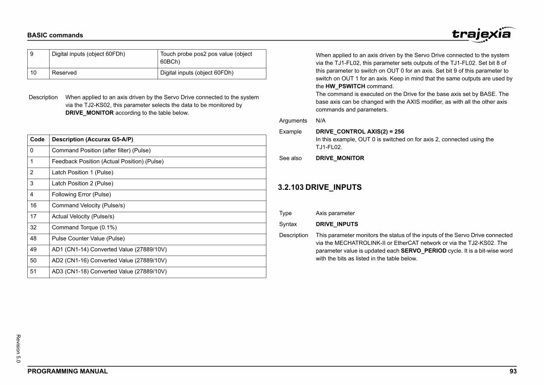
BASIC
PROG 93
Revision 5.0
9
10
Descr
Code
0
1
2
3
4
16
17
32
48
49
50
51
axis driven by the Servo Drive connected to the system is parameter sets outputs of the TJ1-FL02. Set bit 8 of itch on OUT 0 for an axis. Set bit 9 of this parameter to an axis. Keep in mind that the same outputs are used by ommand.cuted on the Drive for the base axis set by BASE. The nged with the AXIS modifier, as with all the other axis
meters.
XIS(2) = 256 0 is switched on for axis 2, connected using the
itors the status of the inputs of the Servo Drive connected LINK-II or EtherCAT network or via the TJ2-KS02. The pdated each SERVO_PERIOD cycle. It is a bit-wise word in the table below.
commands
RAMMING MANUAL
/i
3.2.103 DRIVE_INPUTS/i
Digital inputs (object 60FDh) Touch probe pos2 pos value (object 60BCh)
Reserved Digital inputs (object 60FDh)
iption When applied to an axis driven by the Servo Drive connected to the system via the TJ2-KS02, this parameter selects the data to be monitored by DRIVE_MONITOR according to the table below.
Description (Accurax G5-A/P)
Command Position (after filter) (Pulse)
Feedback Position (Actual Position) (Pulse)
Latch Position 1 (Pulse)
Latch Position 2 (Pulse)
Following Error (Pulse)
Command Velocity (Pulse/s)
Actual Velocity (Pulse/s)
Command Torque (0.1%)
Pulse Counter Value (Pulse)
AD1 (CN1-14) Converted Value (27889/10V)
AD2 (CN1-16) Converted Value (27889/10V)
AD3 (CN1-18) Converted Value (27889/10V)
When applied to an via the TJ1-FL02, ththis parameter to swswitch on OUT 1 for the HW_PSWITCH cThe command is exebase axis can be chacommands and para
Arguments N/A
Example DRIVE_CONTROL AIn this example, OUTTJ1-FL02.
See also DRIVE_MONITOR
Type Axis parameter
Syntax DRIVE_INPUTS
Description This parameter monvia the MECHATROparameter value is uwith the bits as listed
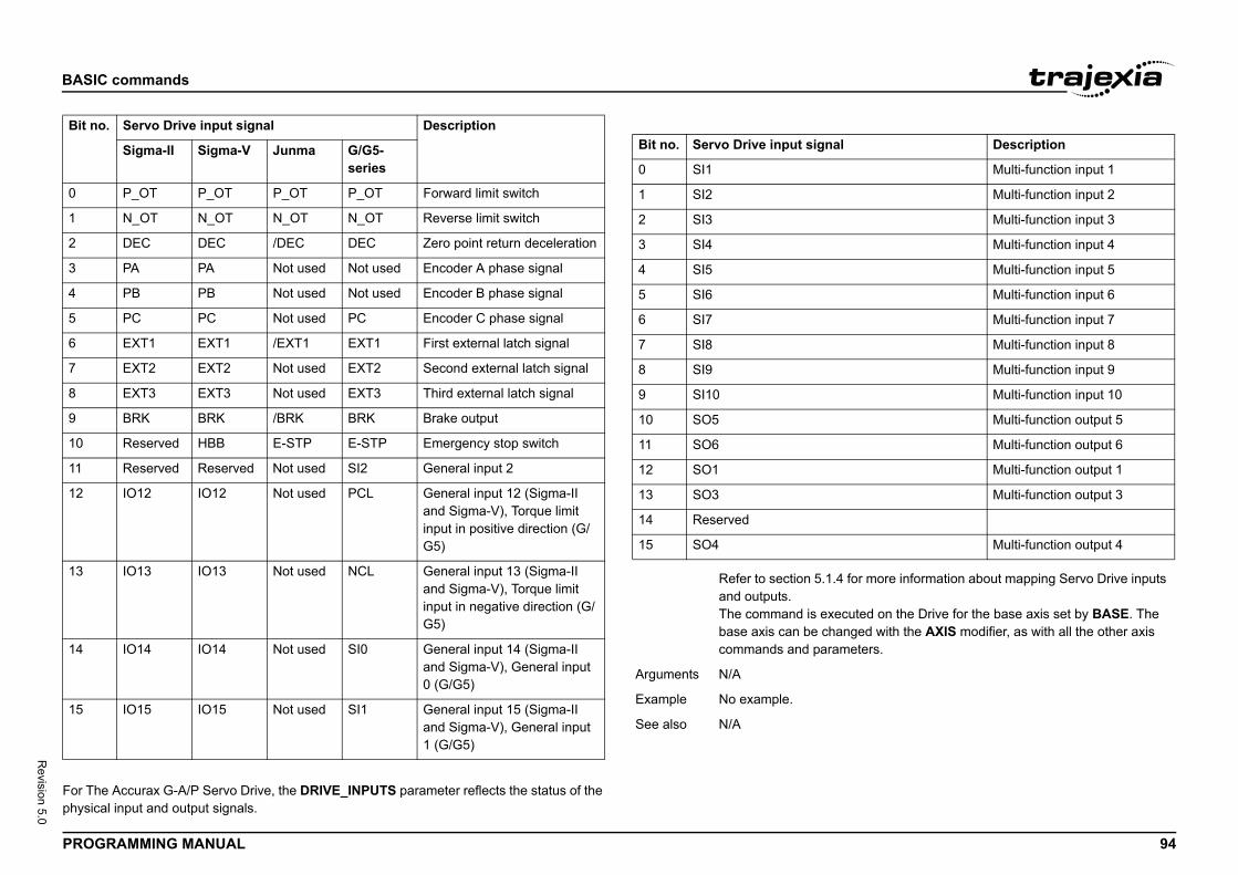
BASIC
PROG 94
Revision 5.0
/i
For Thphysic
Bit no
0
1
2
3
4
5
6
7
8
9
10
11
12
13
14
15
l Description
Multi-function input 1
Multi-function input 2
Multi-function input 3
Multi-function input 4
Multi-function input 5
Multi-function input 6
Multi-function input 7
Multi-function input 8
Multi-function input 9
Multi-function input 10
Multi-function output 5
Multi-function output 6
Multi-function output 1
Multi-function output 3
Multi-function output 4
4 for more information about mapping Servo Drive inputs
cuted on the Drive for the base axis set by BASE. The nged with the AXIS modifier, as with all the other axis
meters.
commands
RAMMING MANUAL
e Accurax G-A/P Servo Drive, the DRIVE_INPUTS parameter reflects the status of the al input and output signals.
. Servo Drive input signal Description
Sigma-II Sigma-V Junma G/G5-series
P_OT P_OT P_OT P_OT Forward limit switch
N_OT N_OT N_OT N_OT Reverse limit switch
DEC DEC /DEC DEC Zero point return deceleration
PA PA Not used Not used Encoder A phase signal
PB PB Not used Not used Encoder B phase signal
PC PC Not used PC Encoder C phase signal
EXT1 EXT1 /EXT1 EXT1 First external latch signal
EXT2 EXT2 Not used EXT2 Second external latch signal
EXT3 EXT3 Not used EXT3 Third external latch signal
BRK BRK /BRK BRK Brake output
Reserved HBB E-STP E-STP Emergency stop switch
Reserved Reserved Not used SI2 General input 2
IO12 IO12 Not used PCL General input 12 (Sigma-II and Sigma-V), Torque limit input in positive direction (G/G5)
IO13 IO13 Not used NCL General input 13 (Sigma-II and Sigma-V), Torque limit input in negative direction (G/G5)
IO14 IO14 Not used SI0 General input 14 (Sigma-II and Sigma-V), General input 0 (G/G5)
IO15 IO15 Not used SI1 General input 15 (Sigma-II and Sigma-V), General input 1 (G/G5)
Bit no. Servo Drive input signa
0 SI1
1 SI2
2 SI3
3 SI4
4 SI5
5 SI6
6 SI7
7 SI8
8 SI9
9 SI10
10 SO5
11 SO6
12 SO1
13 SO3
14 Reserved
15 SO4
Refer to section 5.1.and outputs.The command is exebase axis can be chacommands and para
Arguments N/A
Example No example.
See also N/A
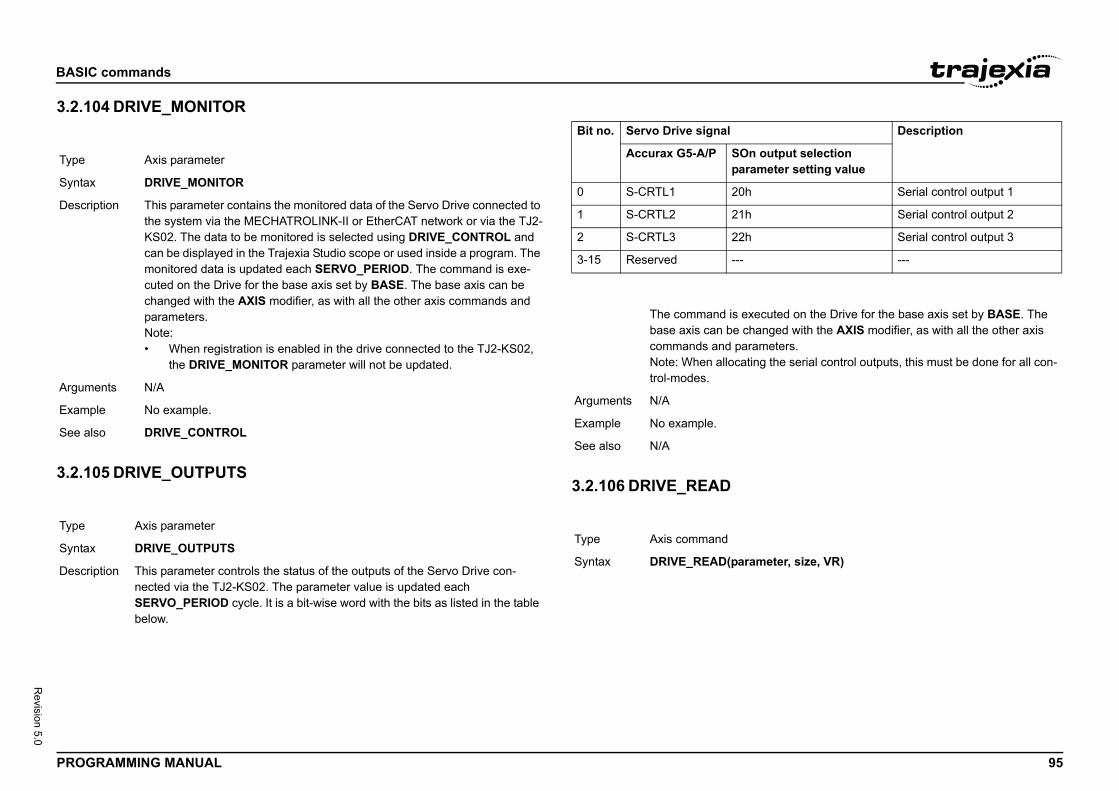
BASIC
PROG 95
Revision 5.0
3.2.1/i
3.2.1/i
Type
Synta
Descr
Argum
Exam
See a
Type
Synta
Descr
Description
output selectionmeter setting value
Serial control output 1
Serial control output 2
Serial control output 3
---
cuted on the Drive for the base axis set by BASE. The nged with the AXIS modifier, as with all the other axis
meters.g the serial control outputs, this must be done for all con-
meter, size, VR)
commands
RAMMING MANUAL
04 DRIVE_MONITOR
05 DRIVE_OUTPUTS
/i
3.2.106 DRIVE_READ/i
Axis parameter
x DRIVE_MONITOR
iption This parameter contains the monitored data of the Servo Drive connected to the system via the MECHATROLINK-II or EtherCAT network or via the TJ2-KS02. The data to be monitored is selected using DRIVE_CONTROL and can be displayed in the Trajexia Studio scope or used inside a program. The monitored data is updated each SERVO_PERIOD. The command is exe-cuted on the Drive for the base axis set by BASE. The base axis can be changed with the AXIS modifier, as with all the other axis commands and parameters.Note:• When registration is enabled in the drive connected to the TJ2-KS02,
the DRIVE_MONITOR parameter will not be updated.
ents N/A
ple No example.
lso DRIVE_CONTROL
Axis parameter
x DRIVE_OUTPUTS
iption This parameter controls the status of the outputs of the Servo Drive con-nected via the TJ2-KS02. The parameter value is updated each SERVO_PERIOD cycle. It is a bit-wise word with the bits as listed in the table below.
Bit no. Servo Drive signal
Accurax G5-A/P SOnpara
0 S-CRTL1 20h
1 S-CRTL2 21h
2 S-CRTL3 22h
3-15 Reserved ---
The command is exebase axis can be chacommands and paraNote: When allocatintrol-modes.
Arguments N/A
Example No example.
See also N/A
Type Axis command
Syntax DRIVE_READ(para
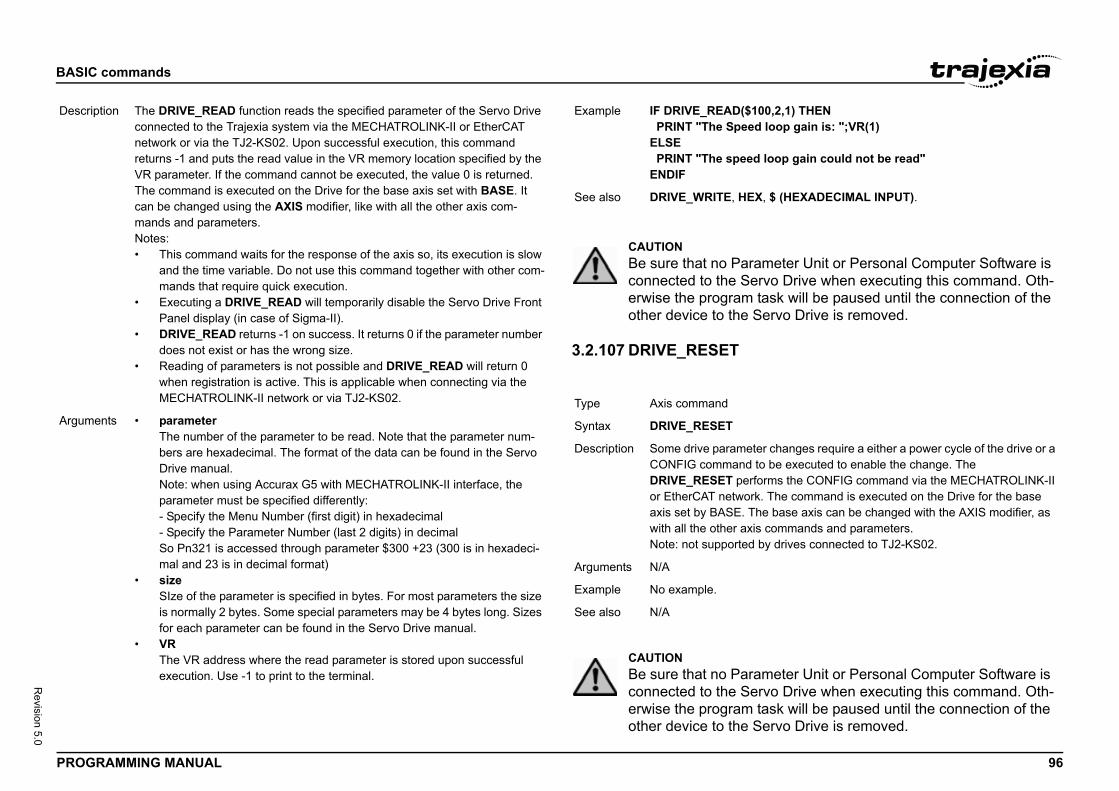
BASIC
PROG 96
Revision 5.0
Descr
Argum
00,2,1) THEN loop gain is: ";VR(1)
loop gain could not be read"
, $ (HEXADECIMAL INPUT).
meter Unit or Personal Computer Software is rvo Drive when executing this command. Oth-task will be paused until the connection of the ervo Drive is removed.
er changes require a either a power cycle of the drive or a o be executed to enable the change. The orms the CONFIG command via the MECHATROLINK-II . The command is executed on the Drive for the base e base axis can be changed with the AXIS modifier, as commands and parameters.by drives connected to TJ2-KS02.
meter Unit or Personal Computer Software is rvo Drive when executing this command. Oth-task will be paused until the connection of the ervo Drive is removed.
commands
RAMMING MANUAL
3.2.107 DRIVE_RESET/i
iption The DRIVE_READ function reads the specified parameter of the Servo Drive connected to the Trajexia system via the MECHATROLINK-II or EtherCAT network or via the TJ2-KS02. Upon successful execution, this command returns -1 and puts the read value in the VR memory location specified by the VR parameter. If the command cannot be executed, the value 0 is returned. The command is executed on the Drive for the base axis set with BASE. It can be changed using the AXIS modifier, like with all the other axis com-mands and parameters.Notes:• This command waits for the response of the axis so, its execution is slow
and the time variable. Do not use this command together with other com-mands that require quick execution.
• Executing a DRIVE_READ will temporarily disable the Servo Drive Front Panel display (in case of Sigma-II).
• DRIVE_READ returns -1 on success. It returns 0 if the parameter number does not exist or has the wrong size.
• Reading of parameters is not possible and DRIVE_READ will return 0 when registration is active. This is applicable when connecting via the MECHATROLINK-II network or via TJ2-KS02.
ents • parameterThe number of the parameter to be read. Note that the parameter num-bers are hexadecimal. The format of the data can be found in the Servo Drive manual.Note: when using Accurax G5 with MECHATROLINK-II interface, the parameter must be specified differently:- Specify the Menu Number (first digit) in hexadecimal- Specify the Parameter Number (last 2 digits) in decimalSo Pn321 is accessed through parameter $300 +23 (300 is in hexadeci-mal and 23 is in decimal format)
• sizeSIze of the parameter is specified in bytes. For most parameters the size is normally 2 bytes. Some special parameters may be 4 bytes long. Sizes for each parameter can be found in the Servo Drive manual.
• VRThe VR address where the read parameter is stored upon successful execution. Use -1 to print to the terminal.
Example IF DRIVE_READ($1 PRINT "The SpeedELSE PRINT "The speedENDIF
See also DRIVE_WRITE, HEX
CAUTIONBe sure that no Paraconnected to the Seerwise the program other device to the S
Type Axis command
Syntax DRIVE_RESET
Description Some drive parametCONFIG command tDRIVE_RESET perfor EtherCAT networkaxis set by BASE. Thwith all the other axisNote: not supported
Arguments N/A
Example No example.
See also N/A
CAUTIONBe sure that no Paraconnected to the Seerwise the program other device to the S
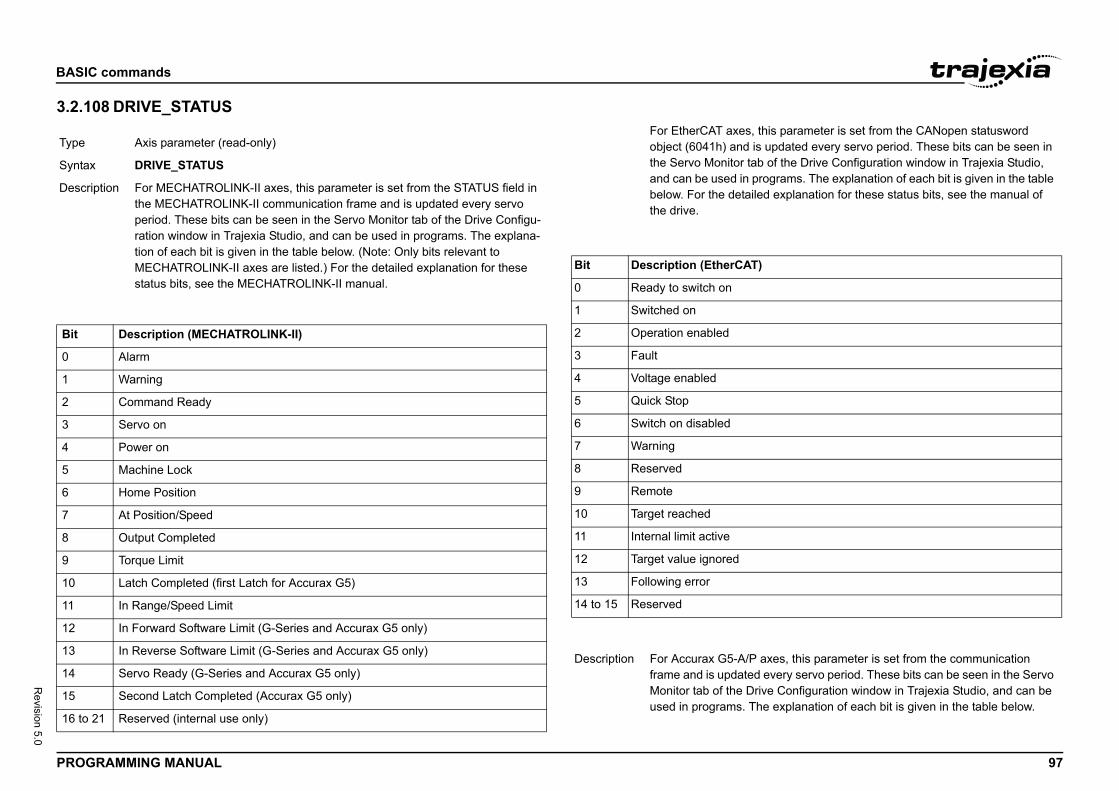
BASIC
PROG 97
Revision 5.0
3.2.1/i
/i
Type
Synta
Descr
Bit
0
1
2
3
4
5
6
7
8
9
10
11
12
13
14
15
16 to
this parameter is set from the CANopen statusword s updated every servo period. These bits can be seen in b of the Drive Configuration window in Trajexia Studio, rograms. The explanation of each bit is given in the table ed explanation for these status bits, see the manual of
)
axes, this parameter is set from the communication every servo period. These bits can be seen in the Servo ive Configuration window in Trajexia Studio, and can be he explanation of each bit is given in the table below.
commands
RAMMING MANUAL
08 DRIVE_STATUS /i
/i
Axis parameter (read-only)
x DRIVE_STATUS
iption For MECHATROLINK-II axes, this parameter is set from the STATUS field in the MECHATROLINK-II communication frame and is updated every servo period. These bits can be seen in the Servo Monitor tab of the Drive Configu-ration window in Trajexia Studio, and can be used in programs. The explana-tion of each bit is given in the table below. (Note: Only bits relevant to MECHATROLINK-II axes are listed.) For the detailed explanation for these status bits, see the MECHATROLINK-II manual.
Description (MECHATROLINK-II)
Alarm
Warning
Command Ready
Servo on
Power on
Machine Lock
Home Position
At Position/Speed
Output Completed
Torque Limit
Latch Completed (first Latch for Accurax G5)
In Range/Speed Limit
In Forward Software Limit (G-Series and Accurax G5 only)
In Reverse Software Limit (G-Series and Accurax G5 only)
Servo Ready (G-Series and Accurax G5 only)
Second Latch Completed (Accurax G5 only)
21 Reserved (internal use only)
For EtherCAT axes, object (6041h) and ithe Servo Monitor taand can be used in pbelow. For the detailthe drive.
Bit Description (EtherCAT
0 Ready to switch on
1 Switched on
2 Operation enabled
3 Fault
4 Voltage enabled
5 Quick Stop
6 Switch on disabled
7 Warning
8 Reserved
9 Remote
10 Target reached
11 Internal limit active
12 Target value ignored
13 Following error
14 to 15 Reserved
Description For Accurax G5-A/Pframe and is updatedMonitor tab of the Drused in programs. T
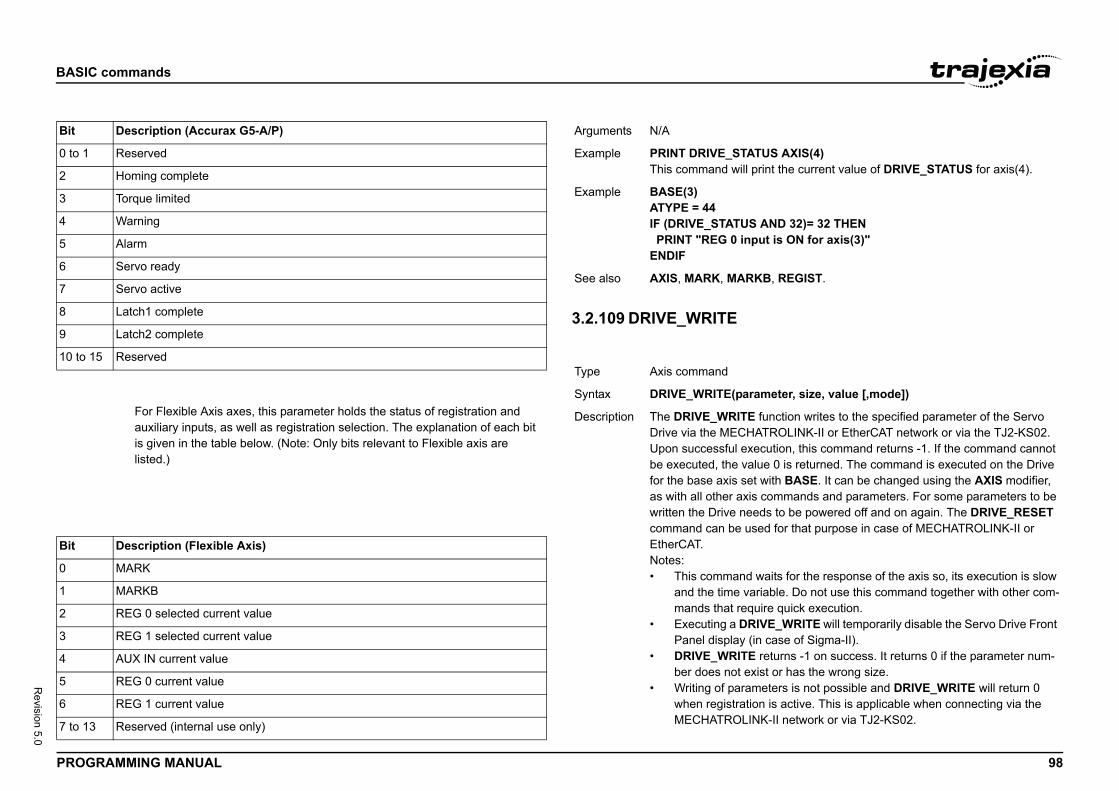
BASIC
PROG 98
Revision 5.0
/i
i
Bit
0 to 1
2
3
4
5
6
7
8
9
10 to
Bit
0
1
2
3
4
5
6
7 to 1
US AXIS(4)rint the current value of DRIVE_STATUS for axis(4).
AND 32)= 32 THENut is ON for axis(3)"
B, REGIST.
meter, size, value [,mode])
function writes to the specified parameter of the Servo TROLINK-II or EtherCAT network or via the TJ2-KS02. cution, this command returns -1. If the command cannot ue 0 is returned. The command is executed on the Drive with BASE. It can be changed using the AXIS modifier, commands and parameters. For some parameters to be ds to be powered off and on again. The DRIVE_RESET ed for that purpose in case of MECHATROLINK-II or
waits for the response of the axis so, its execution is slow riable. Do not use this command together with other com-ire quick execution.
IVE_WRITE will temporarily disable the Servo Drive Front case of Sigma-II).
returns -1 on success. It returns 0 if the parameter num-ist or has the wrong size.eters is not possible and DRIVE_WRITE will return 0 n is active. This is applicable when connecting via the K-II network or via TJ2-KS02.
commands
RAMMING MANUAL
/i
3.2.109 DRIVE_WRITE/i
Description (Accurax G5-A/P)
Reserved
Homing complete
Torque limited
Warning
Alarm
Servo ready
Servo active
Latch1 complete
Latch2 complete
15 Reserved
For Flexible Axis axes, this parameter holds the status of registration and auxiliary inputs, as well as registration selection. The explanation of each bit is given in the table below. (Note: Only bits relevant to Flexible axis are listed.)
Description (Flexible Axis)
MARK
MARKB
REG 0 selected current value
REG 1 selected current value
AUX IN current value
REG 0 current value
REG 1 current value
3 Reserved (internal use only)
Arguments N/A
Example PRINT DRIVE_STATThis command will p
Example BASE(3)ATYPE = 44 IF (DRIVE_STATUS PRINT "REG 0 inpENDIF
See also AXIS, MARK, MARK
Type Axis command
Syntax DRIVE_WRITE(para
Description The DRIVE_WRITE Drive via the MECHAUpon successful exebe executed, the valfor the base axis setas with all other axiswritten the Drive neecommand can be usEtherCAT.Notes:• This command
and the time vamands that requ
• Executing a DRPanel display (in
• DRIVE_WRITEber does not ex
• Writing of paramwhen registratioMECHATROLIN
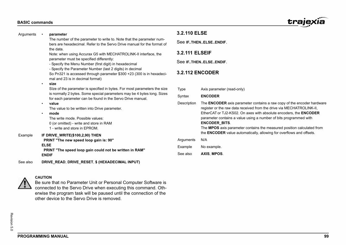
BASIC
PROG 99
Revision 5.0
Argum
Exam
See a
-only)
parameter contains a raw copy of the encoder hardware ata received from the drive via MECHATROLINK-II, 02. On axes with absolute encoders, the ENCODER value using a number of bits programmed with
meter contains the measured position calculated from automatically, allowing for overflows and offsets.
commands
RAMMING MANUAL
3.2.110 ELSE
See IF..THEN..ELSE..ENDIF.
3.2.111 ELSEIF
See IF..THEN..ELSE..ENDIF.
3.2.112 ENCODER/i
ents • parameterThe number of the parameter to write to. Note that the parameter num-bers are hexadecimal. Refer to the Servo Drive manual for the format of the data.Note: when using Accurax G5 with MECHATROLINK-II interface, the parameter must be specified differently:- Specify the Menu Number (first digit) in hexadecimal- Specify the Parameter Number (last 2 digits) in decimalSo Pn321 is accessed through parameter $300 +23 (300 is in hexadeci-mal and 23 is in decimal format)
• sizeSIze of the parameter is specified in bytes. For most parameters the size is normally 2 bytes. Some special parameters may be 4 bytes long. Sizes for each parameter can be found in the Servo Drive manual.
• valueThe value to be written into Drive parameter.
• modeThe write mode. Possible values:0 (or omitted) - write and store in RAM1 - write and store in EPROM.
ple IF DRIVE_WRITE($100,2,90) THEN PRINT "The new speed loop gain is: 90"ELSE PRINT "The speed loop gain could not be written in RAM"ENDIF
lso DRIVE_READ, DRIVE_RESET, $ (HEXADECIMAL INPUT)
CAUTIONBe sure that no Parameter Unit or Personal Computer Software is connected to the Servo Drive when executing this command. Oth-erwise the program task will be paused until the connection of the other device to the Servo Drive is removed.
Type Axis parameter (read
Syntax ENCODER
Description The ENCODER axisregister or the raw dEtherCAT or TJ2-KSparameter contains aENCODER_BITS.The MPOS axis parathe ENCODER value
Arguments N/A
Example No example.
See also AXIS, MPOS.
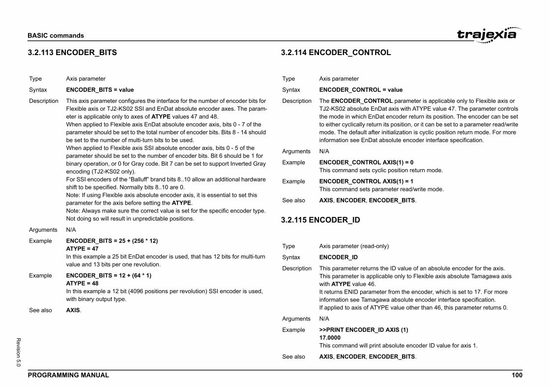
BASIC
PROG 100
Revision 5.0
3.2.1/i
ROL
Type
Synta
Descr
Argum
Exam
Exam
See a
OL = value
NTROL parameter is applicable only to Flexible axis or nDat axis with ATYPE value 47. The parameter controls
nDat encoder return its position. The encoder can be set turn its position, or it can be set to a parameter read/write fter initialization is cyclic position return mode. For more at absolute encoder interface specification.
OL AXIS(1) = 0cyclic position return mode.
OL AXIS(1) = 1parameter read/write mode.
NCODER_BITS.
-only)
ns the ID value of an absolute encoder for the axis.plicable only to Flexible axis absolute Tamagawa axis .
meter from the encoder, which is set to 17. For more agawa absolute encoder interface specification.TYPE value other than 46, this parameter returns 0.
_ID AXIS (1)
rint absolute encoder ID value for axis 1.
NCODER_BITS.
commands
RAMMING MANUAL
13 ENCODER_BITS 3.2.114 ENCODER_CONT/i
3.2.115 ENCODER_ID/i
Axis parameter
x ENCODER_BITS = value
iption This axis parameter configures the interface for the number of encoder bits for Flexible axis or TJ2-KS02 SSI and EnDat absolute encoder axes. The param-eter is applicable only to axes of ATYPE values 47 and 48.When applied to Flexible axis EnDat absolute encoder axis, bits 0 - 7 of the parameter should be set to the total number of encoder bits. Bits 8 - 14 should be set to the number of multi-turn bits to be used.When applied to Flexible axis SSI absolute encoder axis, bits 0 - 5 of the parameter should be set to the number of encoder bits. Bit 6 should be 1 for binary operation, or 0 for Gray code. Bit 7 can be set to support Inverted Gray encoding (TJ2-KS02 only).For SSI encoders of the “Balluff” brand bits 8..10 allow an additional hardware shift to be specified. Normally bits 8..10 are 0. Note: If using Flexible axis absolute encoder axis, it is essential to set this parameter for the axis before setting the ATYPE.Note: Always make sure the correct value is set for the specific encoder type. Not doing so will result in unpredictable positions.
ents N/A
ple ENCODER_BITS = 25 + (256 * 12)ATYPE = 47In this example a 25 bit EnDat encoder is used, that has 12 bits for multi-turn value and 13 bits per one revolution.
ple ENCODER_BITS = 12 + (64 * 1)ATYPE = 48In this example a 12 bit (4096 positions per revolution) SSI encoder is used, with binary output type.
lso AXIS.
Type Axis parameter
Syntax ENCODER_CONTR
Description The ENCODER_COTJ2-KS02 absolute Ethe mode in which Eto either cyclically remode. The default ainformation see EnD
Arguments N/A
Example ENCODER_CONTRThis command sets
Example ENCODER_CONTRThis command sets
See also AXIS, ENCODER, E
Type Axis parameter (read
Syntax ENCODER_ID
Description This parameter returThis parameter is apwith ATYPE value 46It returns ENID parainformation see TamIf applied to axis of A
Arguments N/A
Example >>PRINT ENCODER17.0000This command will p
See also AXIS, ENCODER, E
BASIC
PROG 101
Revision 5.0
3.2.1/i
Type
Synta
Descr
Argum
t to the encoder resolution that can be devided by anrees. (7200/20=360)
8192,7200)librated in degrees, resolution is 0.05 deg.ervo motor connected directly to its centre of rotation. An to the rear of the servo motor and returns a value of lution. The application requires the table to be calibrated at one degree is an integer number of counts.
ATIO and STEP_RATIO to perform gearing on an
8192,7200,1)ands will result in the same settings:8192,7200)8192)
ddress)
AD command is applicable only to Flexible axis or nDat axis with ATYPE value 47. The parameter returns a eter stored at specified address. Bits 8 -15 of the
at MRS field settings and bits 0 - 7 are the offset within k. If a CRC error occurs, this command will return -1. For EnDat absolute encoder interface specification.
Dat MRS field to read.
R_READ($A10D) AXIS(7)ad the number of encoder bits and put that value in tion.
NCODER_BITS.
commands
RAMMING MANUAL
16 ENCODER_RATIO
3.2.117 ENCODER_READ/i
Axis parameter
x ENCODER_RATIO(numerator,denominator [,option])
iption This command allows the incoming encoder count to be scaled by a non inte-ger number, using the equation:MPOS = (numerator / demoninator) x encoder_edges_inputUnlike the UNITS parameters, ENCODER_RATIO affects commands like MOVECIRC and CAMBOX, since it affects the number of encoder edges within the servo loop at the low level. It is necessary to change the position loop gains after changing encoder ratio in order to maintain performance and stability.Notes:• Large ratios should be avoided as they will lead to either loss of resolu-
tion or much reduced smoothness in the motion. The actual physical encoder count is the basic resolution of the axis and the use of this com-mand may reduce the ability of the Motion Controller to accurately achieve all positions.
• ENCODER_RATIO does not replace UNITS. Only use ENCODER_RATIO where absolutely necessary. For all other axis scal-ing use UNITS.
• ENCODER_RATIO only scales the position feedback, not the position command. When using it with MECHATROLINK or EtherCAT position axes, both the position feedback and position command must be scaled. Scaling the position command is done with STEP_RATIO. When setting the option parameter to 1, automatically STEP_RATIO will be set with the reciprocated values.
• Executing ENCODER_RATIO without parameters will print the current numerator and denominator.
ents • numeratorA number between 0 and 16777215 that is used to define the numerator in the above equation.
• denominatorA number between 0 and 16777215 that is used to define the denomina-tor in the above equation.
• optionOptional parameter to set STEP_RATIO with the reciprocated values.
Example ' 7200 is the closes' integer to give degENCODER_RATIO(UNITS=20 ' axis caA rotary table has a sencoder is mounted 8192 counts per revoin degrees, but so th
Example Using ENCODER_REtherCAT drive.ENCODER_RATIO(The following commENCODER_RATIO(STEP_RATIO(7200,
See also STEP_RATIO
Type Axis command
Syntax ENCODER_READ(a
Description The ENCODER_RETJ2-KS02 absolute E16-bit encoder paramaddress are the EnDthe EnDat MRS blocmore information see
Arguments • addressSpecifies the En
Example VR(100) = ENCODEThis command will reVR(10) memory loca
See also AXIS, ENCODER, E
BASIC
PROG 102
Revision 5.0
3.2.1/i
3.2.1/i
E
Type
Synta
Descr
Argum
Exam
See a
Type
Synta
Descr
Argum
Exam
See a
address, value)
ITE command is applicable only to Flexible axis or nDat axis with ATYPE value 47. The command writes to
er specified by the address. Bits 8 -15 of the address are settings and bits 0 - 7 are the offset within the EnDat error occurs, this command will return 0. Writing to
an encoder reset function.For more information see der interface specification.In order to successfully write
er with this command, the ENCODER_CONTROL et to 1, encoder parameter read/write mode.
Dat MRS field to write to.
expression.
NCODER_BITS, ENCODER_CONTROL.
o examine the end direction in radians of the last pro-MOVEABSSP/MOVECIRCSP move of 2 or more axes. l be the same as START_DIR_LAST except in the case D_DIR_LAST is used by the system to calculate the
n a new move is loaded. END_DIR_LAST can be written ired when initialising a system or after a sequence of t MOVESP/MOVEABSSP/MOVECIRCSP moves of 2 or
commands
RAMMING MANUAL
18 ENCODER_STATUS
19 ENCODER_TURNS
3.2.120 ENCODER_WRIT/i
3.2.121 END_DIR_LAST/i
Axis parameter (read-only).
x ENCODER_STATUS
iption This parameter returns the status of the absolute encoder.This parameter is applicable only to Flexible axis absolute Tamagawa axis with ATYPE value 46. It returns both the status field SF and the ALMC encoder error field. The SF field is in bits 0 - 7, while the ALMC filed is in bits 8 - 15. For more information see Tamagawa absolute encoder interface specification.If applied to axis of ATYPE value other than 46, this parameter returns 0.
ents N/A
ple PRINT (ENCODER_STATUS AXIS (1) AND 255)This command will print SF field of the Tamagawa absolute encoder for axis 1.
lso AXIS, ENCODER, ENCODER_BITS.
Axis parameter (read-only)
x ENCODER_TURNS
iption The ENCODER_TURNS parameter returns the number of multi-turn count from the encoder.This is applicable only to Flexible axis absolute Tamagawa axis with ATYPE value 46 and Flexible axis or TJ2--KS02 absolute EnDat axis with ATYPE value 47.The multi-turn data is not automatically applied to the axis MPOS parameter after initialization. The application programmer must apply this from the pro-gram using OFFPOS or DEFPOS commands as required.If applied to axis of ATYPE value other than 46 or 47, the parameter returns 0.
ents N/A
ple PRINT ENCODER_TURNS AXIS (1)This command will print absolute encoder multi-turn counts for axis 1.
lso AXIS, ENCODER, ENCODER_BITS.
Type Axis command
Syntax ENCODER_WRITE(
Description The ENCODER_WRTJ2-KS02 absolute Ean encoder parametthe EnDat MRS fieldMRS block. If a CRCaddress 0 performs EnDat absolute encoan encoder parametparameter must be s
Arguments • addressSpecifies the En
• valueAny valid BASIC
Example No example.
See also AXIS, ENCODER, E
Type Axis parameter
Syntax END_DIR_LAST
Description Allows the program tgrammed MOVESP/END_DIR_LAST wilof circular moves. ENchange in angle wheto. This is often requmoves which are nomore axes.
Arguments N/A
BASIC
PROG 103
Revision 5.0
3.2.1
See I
3.2.1/i
3.2.1/i
DExam
See a
Type
Synta
Descr
Argum
Exam
See a
Type
Synta
Descr
Argum
Exam
See a
= value
EED parameter is used to directly control the ramp to exit peed moves (MOVESP, MOVEABSSP, MOVECIRCSP, ) MOVE_SPEED parameter should be set to the required
oading the move into the buffer.ove types are merged, the speed at the merge point is
DMOVE_SPEED of the outgoing move. If a forced speed more non-forced speed moves the deceleration will occur D of the incoming move.
=2000
SPEED
ead-only)
xis parameter contains the number of the axis which has rror.s when the AXISSTATUS state for one of the axes MASK setting. In this case the enable switch (WDOG) MOTION_ERROR parameter will have value different R_AXIS parameter will contain the number of the first
r.
RORMASK, MOTION_ERROR, WDOG.
commands
RAMMING MANUAL
22 ENDIF
F..THEN..ELSE..ENDIF.
23 ENDMOVE
24 ENDMOVE_BUFFER
3.2.125 ENDMOVE_SPEE/i
3.2.126 ERROR_AXIS/i
ple >>MOVESP(10000,-10000)>>? END_DIR_LAST2.3562
lso MOVESP, START_DIR_LAST.
Axis parameter
x ENDMOVE
iption The ENDMOVE axis parameter holds the position of the end of the current move in user units. If the SERVO axis parameter is ON, the ENDMOVE param-eter can be written to produce a step change in the demand position (DPOS).Note: As the measured position is not changed initially, the Following Error limit (FE_LIMIT) should be considered when writing to ENDMOVE to produce a step change. If the change of demanded position is too big, the limit will be exceeded.
ents N/A
ple No example.
lso AXIS, DPOS, FE_LIMIT, UNIT_INIT.
Axis parameter (read only)
x ENDMOVE_BUFFER
iption This holds the absolute position at the end of the buffered sequence. It is adjusted by OFFPOS/DEFPOS. The individual moves in the buffer are incre-mental and do not need to be adjusted by OFFPOS.
ents N/A
ple No example.
lso MOVES_BUFFERED, USER_FRAME
Type Axis parameter
Syntax ENDMOVE_SPEED
Description The ENDMOVE_SPspeed when forced sare loaded. The ENDvalue at the time of lIf two forced speed mcontrolled by the ENmove follows one or to the FORCE_SPEE
Arguments N/A
Example ENDMOVE_SPEED
See also MOVESP, FORCE_
Type System parameter (r
Syntax ERROR_AXIS
Description The ERROR_AXIS acaused the motion eA motion error occurmatches the ERRORwill be turned off, thethan 0 and the ERROaxis to have the erro
Arguments N/A
Example No example.
See also AXIS_FS_LIMIT, ER
BASIC
PROG 104
Revision 5.0
3.2.1/i
3.2.1/i
Type
Synta
Descr
Argum
Exam
See a
Type
Synta
Descr
Argum
Exam
See a
define in which cases a motion error is gener-tion it is strongly recommended to generate a e Following Error has exceeded its limit in all
by setting bit 8 of ERRORMASK
n, parameter1 [,parameter2 …])
and access the EtherCAT network and its functions.
waits for the response of the device so, its execution is e variable. Do not use this command together with other
require quick execution. command returns -1 (TRUE) on success and 0
ure.
number)EtherCAT network, attached to the EtherCAT master at specified.
itialise the EtherCAT network
the EtherCAT master
commands
RAMMING MANUAL
27 ERROR_LINE
28 ERRORMASK
3.2.129 ETHERCAT/i
Task parameter (read-only)
x ERROR_LINE
iption The ERROR_LINE parameter contains the number of the line which caused the last BASIC run-time error in the program task. This value is only valid when the BASICERROR parameter is TRUE.Each task has its own ERROR_LINE parameter. Use the PROC modifier to access the parameter for a certain task. Without PROC, the current task will be assumed.
ents N/A
ple >> PRINT ERROR_LINE PROC(4)23.0000
lso BASICERROR, PROC, RUN_ERROR.
Axis parameter
x ERRORMASK
iption The ERRORMASK axis parameter contains a mask value that is ANDed bit by bit with the AXISSTATUS axis parameter on every servo cycle to deter-mine if a motion error has occurred. If the result of the AND operation is not zero, the motion error has occurred.When a motion error occurs the enable switch (WDOG) will be turned off, the MOTION_ERROR parameter will have value different than 0 and the ERROR_AXIS parameter will contain the number of the first axis to have the error.Check the AXISSTATUS parameter for the status bit allocations. The default setting of ERRORMASK is 268.
ents N/A
ple No example.
lso AXIS, AXIS_FS_LIMIT, MOTION_ERROR, WDOG.
CAUTIONIt is up to the user toated. For safe operamotion error when thcases. This is done
Type System command
Syntax ETHERCAT(functio
Description Command to controlNotes:• This command
slow and the timcommands that
• The ETHERCAT(FALSE) on fail
Arguments ETHERCAT(0, unit_To initialise the the unit number
• function 0Function 0 to in
• unit_numberUnit number of
BASIC
PROG 105
Revision 5.0
Exam
it_number, address, VR_start_RxPDO, , VR_start_TxPDO, VR_length_TxPDO)
figure the mapping between FZM1 or FQ-M Vision sen-C__
the EtherCAT master to which the slave is attached.
ress of the EtherCAT slaveOress in VR memory of the controller where the data to DO) is mapped (default = 0)DOR locations to allocate data to the device (RxPDO) (one efault = 0)Oress in VR memory of the controller where the data from DO) is mapped (default = 0)DOR locations to allocate data from the device (TxPDO)
VR, default = 0)
le maps the FZM1 (address 1001) Command area to VR and the Response and Output area to VR locations 200 the command was successful.,1001,100,5,200,12) THEN
: OK"
: FAIL"
commands
RAMMING MANUAL
When initialising the EtherCAT network the following is printed to the terminal:EtherCAT State: Init (0)EtherCAT State: Pre-Operational (0)EtherCAT State: Safe-Operational (0)EtherCAT State: Operational (0)EtherCAT Configuration (0): DeviceName : A : B : C (D)
DeviceName: Shows a short name of the connected device.A: The node location on the network. 0 = first node, 1 = second node etc.B: The Node Address set by switches or an EPROM parameter in the node.C: The Node Address assigned by the TJ2-MC__D: The Axis number assigned to the drive by the TJ2-MC__, or
The I/O introduced by the device to the system, in the following format:(D1:D2 / D3:D4 / D5:D6 / D7:D8)D1: start of digital inputsD2: number of digital inputsD3: start of digital outputsD4: number of digital outputsD5: start of analog inputsD6: number of analog inputsD7: start of analog outputsD8: number of analog outputs
ple EtherCAT State: Init (0)EtherCAT State: Pre-Operational (0)EtherCAT State: Safe-Operational (0)EtherCAT State: Operational (0)EtherCAT Configuration (0): GRT1 : 0 : 1 : 1001 (0:0/32:8/0:2/0:0) R88D-KN01H : 1 : 10 : 10 (9)This system contains one GRT1-ECT at node address 1001, with 8 digital outputs (32 to 39) and 2 analog inputs (0 and 1) and one G5-ECT Servo drive at node address 10 and axis 9.
ETHERCAT($66, unVR_length_RxPDO• function $66
Function to consors and TJ2-M
• unit_numberUnit number of
• addressConfigured add
• VR_start_RxPDThe starting addthe device (RxP
• VR_length_RxPThe number of Vobject per VR, d
• VR_start_TxPDThe starting addthe device (TxP
• VR_length_TxPThe number of V(one object per
Example The following examplocations 100 to 104to 211 and checks if IF ETHERCAT($66,0 PRINT "MappingELSE PRINT "MappingENDIF
See also N/A
BASIC
PROG 106
Revision 5.0
3.2.1/i
Type
Synta
Descr
Argum
Exam
See a
as if it were being powered up again.of reset performed by the EX command. EX without the oes the software reset of the controller. EX(1) does the
e controller, also resetting the communication interface. y to make a changed IP address effective.
n
turns the exponential value of the expression.
expression.
commands
RAMMING MANUAL
30 ETHERNET 3.2.131 EX/i
3.2.132 EXP/i
System command
x ETHERNET(function, unit_number, parameter [,values])
iption The command ETHERNET is used to read and set certain functions of Ether-net communications. The ETHERNET command should be entered on the command line of the terminal window of Trajexia Studio in disconnected mode.Note: The commands with parameters 4,5,7,9,10 and 12 take effect immedi-ately after execution. The commands with parameters 0,2,3 and 8 require a power cycle to Trajexia to enable the new parameters.
ents • function0 = Read, 1 = Write.
• unit_number-1.
• parameter0 = IP Address2 = Subnet Mask3 = MAC address4 = Default Port Number (initialised to 23)5 = Token Port Number (initialised to 3240, used by Trajexia Studio)7 = ModbusTCP mode: Integer (0) or IEEE floating point (1)8 = Default Gateway9 = Data configuration: VR variables (0) or TABLE (1)10 = ModbusTCP Port Number (initialised to 502)11 = ARP cache (read-only).12 = Default FINS Port Number (initialised to 9600), see also section 4.2.2.
• valuesThe required parameter for a write.
ple ETHERNET(1,-1,0,192,200,185,2)Set the Trajexia IP address to 192.200.185.2.
lso N/A
Type System command
Syntax EX[(option)]
Description Resets the controllerThere are two types argument, or EX(0) dhardware reset of thThis e.g. is necessar
Arguments N/A
Example No example.
See also N/A
Type Mathematical functio
Syntax EXP(expression)
Description The EXP function re
Arguments • expressionAny valid BASIC
Example >>PRINT EXP(1.0)2.7183
See also N/A
BASIC
PROG 107
Revision 5.0
3.2.1/i
3.2.1/i
Type
Synta
Descr
Argum
Exam
See a
Type
Synta
Descr
Argum
Exam
See a
parameter contains fast deceleration ration. Its default n-zero FASTDEC is specified, the axis will ramp to zero ate when an axis limit switch or position is reached.
-only)
ter contains the position error in user units. This is calcu- position (DPOS axis parameter) minus the measured parameter). The value of the Following Error can be axis parameters FE_LIMIT and FE_RANGE.
MIT, FE_RANGE, MPOS, UNIT_INIT.
commands
RAMMING MANUAL
33 FALSE
34 FAST_JOG
3.2.135 FASTDEC/i
3.2.136 FE/i
Constant (read-only)
x FALSE
iption The FALSE constant returns the numerical value 0.
ents N/A
ple test: res = IN(0) OR IN(2) IF res = FALSE THEN PRINT "Inputs are off" ENDIF
lso N/A
Axis parameter
x FAST_JOG
iption The FAST_JOG axis parameter contains the input number to be used as the fast jog input. The number can be from 0 to 31. As default the parameter is set to -1, no input is used for the fast jog.The fast jog input controls the jog speed between two speeds. If the fast jog input is set, the speed as given by the SPEED axis parameter will be used for jogging. If the input is not set, the speed given by the JOGSPEED axis parameter will be used.Note: This input is active low.
ents N/A
ple No example.
lso AXIS, FWD_JOG, JOGSPEED, REV_JOG, SPEED.
Type Axis parameter
Syntax FASTDEC
Description The FASTDEC axis value is zero. If a noat this deceleration r
Arguments N/A
Example No example.
See also N/A
Type Axis parameter (read
Syntax FE
Description The FE axis paramelated by the demandposition (MPOS axischecked by using the
Arguments N/A
Example No example.
See also AXIS, DPOS, FE_LI
BASIC
PROG 108
Revision 5.0
3.2.1/i
3.2.1/i
Type
Synta
Descr
Argum
Exam
See a
Type
Synta
Descr
Argum
Exam
See a
alue
r is set to 0, the axis will cause a MOTION_ERROR e FE exceeds the FE_LIMIT value.is set to 1, the axis will only generate a hen the FE exceeds FE_LIMIT during 2 consecutive eans that if FE_LIMIT is exceeded for one servo period
d. FE_LIMIT_MODE is 0.
s parameter contains the limit for the Following Error r units. When the Following Error exceeds this value on the AXISSTATUS axis parameter will be turned on.s a first indication for fault conditions in the application ).
IT, ERRORMASK, FE, UNIT_INIT.
commands
RAMMING MANUAL
37 FE_LATCH
38 FE_LIMIT
3.2.139 FE_LIMIT_MODE/i
3.2.140 FE_RANGE/i
Axis parameter (read-only)
x FE_LATCH
iption Contains the initial FE value which caused the axis to put the controller into MOTION_ERROR. This value is only set when the FE exceeds the FE_LIMIT and the SERVO parameter has been set to OFF. FE_LATCH is reset to 0 when the SERVO parameter of the axis is set back to ON.
ents N/A
ple No example.
lso N/A
Axis parameter
x FE_LIMITFELIMIT
iption The FE_LIMIT axis parameter contains the maximum allowed Following Error in user units. When exceeded, bit 8 of the AXISSTATUS parameter of the axis will be set. If the ERRORMASK parameter has been properly set, a motion error will be generated and WDOG enable relay will be reset to 0.This limit is used to guard against fault conditions, such as mechanical lock-up, loss of encoder feedback, etc.
ents N/A
ple No example.
lso AXIS, AXIS_FS_LIMIT, ERRORMASK, FE, FE_RANGE, UNIT_INIT.
Type Axis parameter
Syntax FE_LIMIT_MODE=v
Description When this parameteimmediately when thIf FE_LIMIT_MODE MOTION_ERROR wservo periods. This monly, it will be ignoreThe default value for
Arguments N/A
Example No example.
See also N/A
Type Axis parameter
Syntax FE_RANGE
Description The FE_RANGE axiwarning range in usea servo axis, bit 1 in This range is used a(compare FE_LIMIT
Arguments N/A
Example No example.
See also AXIS, AXIS_FS_LIM
BASIC
PROG 109
Revision 5.0
3.2.1/i
Type
Synta
Descr
Argum
Exam
See a
parameter contains the feedhold speed. This parameter in user units/s and defines at which speed the axis will hold input turns on. The current move is not cancelled. any positive value including 0. The default value is 0. applicable to most applications as motion is usually o speed when the freehold input is set. In some cases it the axis to ramp to a known constant speed when the
ly works on speed controlled moves. Moves which are (CAMBOX, CONNECT and MOVELINK) are not
IT, FHOLD_IN, UNIT_INIT.
commands
RAMMING MANUAL
41 FHOLD_IN 3.2.142 FHSPEED/i
Axis parameter
x FHOLD_INFH_IN
iption The FHOLD_IN axis parameter contains the input number to be used as the feedhold input. The valid input range is 0 to 31. Values 0 to 15 represent phys-ically present inputs of TJ2-MC__ I/O connector and are common for all axes.Values 16 to 31 are mapped directly to Drive inputs that are present on the CN1 connector. They are unique for each axis. It depends on the type of Servo Drive which Servo Drive inputs are mapped into inputs 16 to 31.As default the parameter is set to -1, no input is used for feedhold.Note: This input is active low.If an input number is set and the feedhold input turns set, the speed of the move on the axis is changed to the value set in the FHSPEED axis parameter. The current move is not cancelled. Furthermore, bit 7 of the AXISSTATUS parameter is set. When the input turns reset again, any move in progress when the input was set will return to the programmed speed.Note: This feature only works on speed controlled moves. Moves which are not speed controlled (CAMBOX, CONNECT and MOVELINK) are not affected.
ents N/A
ple No example.
lso AXIS, AXIS_FS_LIMIT, FHSPEED, UNIT_INIT.
Type Axis parameter
Syntax FHSPEED
Description The FHSPEED axis can be set to a valuemove when the feedFHSPEED can haveThis default value is ramped down to zermay be desirable forfreehold input is set.Note: This feature onnot speed controlledaffected.
Arguments N/A
Example No example.
See also AXIS, AXIS_FS_LIM
BASIC
PROG 110
Revision 5.0
3.2.1/i
Type
Synta
Descr
FINS command. 0 means FINS 0101, read memory from rver. 1 means FINS 0102, write memory to the remote
network. For more details, see the Communication Com-ce Manual, cat. num. W342-E1, Section 3.
destination FINS server. For more details, see the Com-mands Reference Manual, cat. num. W342-E1,
r of the destination FINS server. For more details, see the Commands Reference Manual, cat. num. W342-E1,
ory accessed on the destination FINS server. Range: that this area must be one of the following values if the other Trajexia system: 0xB0: Integer VR value; 0xF0: x82: Integer TABLE value; 0xC2: float TABLE value.
set on the destination FINS server. Range: 0..65535. nge will be more limited to the maximum TABLE or VR destination is another Trajexia system.
tems to be transferred. The range will depend upon the th and the capabilities of the client and remote servers.
Trajexia system is from 1 to 700 integer values, or 1 to t values.
e) memory area. Note that this area must be one of the : 0x00: Integer VR value; 0x01: Integer TABLE value; LE value.
commands
RAMMING MANUAL
43 FINS_COMMS
Communication command
x FINS_COMMS(type, network, node, unit, remote_area, remote_offset, length, local_area, local_offset, timeout [, ip1, ip2, ip3, ip4])
iption FINS (Factory Interface Network Service) is a Proprietary OMRON communi-cation protocol. A subset of this protocol has been implemented in Trajexia. The FINS protocol has been implemented with the intention of enabling seamless communication with other OMRON devices (PLCs, HMIs, etc.) and software (CX-Drive, CX-Server, etc.). For more information on FINS commu-nication protocol, see section 4.2.3 and the Communication Commands Ref-erence Manual, cat. num. W342-E1, Sections 3 and 5.Trajexia has built in FINS client capabilities, so it can initiate the FINS commu-nications with FINS slave devices using FINS_COMMS. Only FINS 0101 (Read Memory) and FINS 0102 (Write Memory) commands are implemented at the moment of this writing. With FINS 0101, memory can be read from other devices with FINS server capability. FINS 0102 can be used to write data to devices with FINS server capability.This command returns one of the following values, depending on outcome of the execution:-1: The command executed successfully.0: The command failed. 1: Request not sent because the client or the FINS protocol is busy.2: One or more of the request parameters are invalid.3: Invalid source memory area.4: Request was sent, but no response from remote server received within timeout period.5: Error response code received from remote server.
Arguments • typeThe type of the remote FINS seserver.
• networkThe destinationmands Referen
• nodeThe node of themunication ComSection 3.
• unitThe unit numbeCommunicationSection 3.
• remote_areaThe area of mem128..255. Note destination is anfloat VR value; 0
• remote_offsetThe memory offNote that this raaddresses if the
• lengthThe number of iFINS frame lengThe range for a350 floating poin
• local_areaThe local (sourcfollowing values0x02 : float TAB
BASIC
PROG 111
Revision 5.0
EXT
Exam
See a
)
RAM to and from the permanent Flash memory.
quired action.entire TABLE to the Flash-ROM and use it to
table data on power-up.the Flash-ROM copy of TABLE during power-up.
LE data to Flash memory.
mand
t TO end [STEP increment]
op allows the program segment between the FOR and to be repeated a number of times., the variable is initialized to the value of start and the s then executed. Upon reaching the NEXT command, the by the increment specified after STEP. The STEP value gative, if omitted the value is assumed to be 1. than or equal to end, the block of commands is repeat-
ariable is greater than end, at which time program execu-r NEXT.statements can be nested up to 8 levels deep in a BASIC
commands
RAMMING MANUAL
3.2.144 FLASHVR/i
3.2.145 FOR..TO..STEP..N/i
• local_offsetThe offset of the first value in the local (source) memory area. The range depends upon the VR or TABLE array size and value for the length argu-ment.
• timeoutThe number of milliseconds to wait for a response from the destination FINS server, before timing out.
• IP1, IP2, IP3, IP4Optional parameters that define the remote (destination) server IP address. These arguments must be used if both the Trajexia system and the destination FINS server do not belong to same network.
ple A Trajexia system and an OMRON CJ1 PLC with Ethernet Unit CJ1W-ETN11 system are connected to the same network. The IP address of Trajexia sys-tem is 192.168.0.5. The IP address of the PLC Ethernet Unit is 192.168.0.12.When you execute the commandFINS_COMMS(0,0,12,0,$82, 1000,20,0,500,5000,192,168,0,12)20 words (length=20) of DM PLC memory area (remote_area=$82) is read, starting from DM1000 (remote_offset=1000), and is written in the Trajexia VR memory in integer format (local_area=0), starting from VR(500) (local_offset=500). So, values in PLC memory range DM1000 to DM1019 are placed in Trajexia memory VR(500) to VR(519). The timeout is set to 5 seconds. When you execute the commandFINS_COMMS(1,0,12,0,$80, 50,10,0,300,3000,192,168,0,12)10 words (length=10) of Trajexia VR memory as integers (local_area=0), starting from VR(300) (local_offset=300), are written to the CIO area of the PLC (remote_area=$80), starting from CIO50 (remote_offset=50). So, val-ues in Trajexia memory range VR(300) to VR(309) are placed in memory CIO50 to CIO59 of the PLC. The timeout is set to 3 seconds.
lso N/A
Type System function
Syntax FLASHVR(function
Description Copies user data in
Arguments • functionSpecifies the re-1 = Stores the replace the RAM-2 = Stop using
Example Save the entire TABFLASHVR(-1)
See also N/A
Type Program control com
Syntax FOR variable = star commandsNEXT variable
Description The FOR ... NEXT lothe NEXT statementOn entering this loopblock of commands ivariable is increasedcan be positive or neWhile variable is lessedly executed until vtion will continue afteNote: FOR ... NEXT program.
BASIC
PROG 112
Revision 5.0
Argum
Exam
Exam
Exam
See a
alue
parameter is used to directly control the speed when (MOVESP, MOVEABSSP, MOVECIRCSP, ) are loaded. parameter should be set to the required value at the ove into the buffer.ove types are merged, the speed at the merge point is
DMOVE_SPEED of the outgoing move. If a forced speed more non-forced speed moves the deceleration will occur D of the incoming move.
00
E_SPEED
mand moves an axis continuously forward at the speed is parameter. The acceleration rate is defined by the ter.
n the default basis axis (set with BASE) unless AXIS is porary base axis.
otion can be stopped by executing the CANCEL or nd, or by reaching the forward limit. If stopped by execu-
or RAPIDSTOP command, the axis decelerates to a stop DECEL rate.
commands
RAMMING MANUAL
3.2.146 FORCE_SPEED/i
3.2.147 FORWARD/i
ents • variableAny valid BASIC expression.
• startAny valid BASIC expression.
• endAny valid BASIC expression.
• incrementAny valid BASIC expression.
• commandsOne or more BASIC commands.
ple FOR opnum = 8 TO 13 OP(opnum,ON)NEXT opnumThis loop turns on outputs 8 to 13.
ple loop: FOR dist = 5 TO -5 STEP -0.25 MOVEABS(dist) GOSUB pick_up NEXT distThe STEP increment can be positive or negative.
ple loop1: FOR l1 = 1 TO 8 loop2: FOR l2 = 1 TO 6 MOVEABS(l1*100,l2*100) GOSUB 1000 NEXT l2 NEXT l1FOR..TO..STEP..NEXT statements can be nested (up to 8 levels deep) pro-vided the inner FOR and NEXT commands are both within the outer FOR..TO..STEP..NEXT loop.
lso REPEAT..UNTIL, WHILE..WEND.
Type Axis parameter
Syntax FORCE_SPEED = v
Description The FORCE_SPEEDforced speed movesThe FORCE_SPEEDtime of loading the mIf two forced speed mcontrolled by the ENmove follows one or to the FORCE_SPEE
Arguments N/A
Example FORCE_SPEED=20
See also MOVESP, ENDMOV
Type Axis command
Syntax FORWARDFO
Description The FORWARD comset in the SPEED axACCEL axis parameFORWARD works oused to specify a temNote: The forward mRAPIDSTOP commation of the CANCEL at the programmed
Arguments N/A
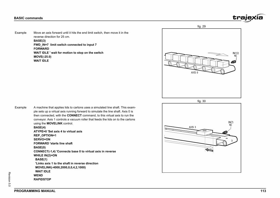
BASIC
PROG 113
Revision 5.0
fig. 29/i
fig. 30/i
IN(12)NC
AXIS 0
Exam
IN(7)NC
AXIS 3
Exam
commands
RAMMING MANUAL
ple Move an axis forward until it hits the end limit switch, then move it in the reverse direction for 25 cm.BASE(3)FWD_IN=7 limit switch connected to input 7FORWARDWAIT IDLE ' wait for motion to stop on the switchMOVE(-25.0)WAIT IDLE
ple A machine that applies lids to cartons uses a simulated line shaft. This exam-ple sets up a virtual axis running forward to simulate the line shaft. Axis 0 is then connected, with the CONNECT command, to this virtual axis to run the conveyor. Axis 1 controls a vacuum roller that feeds the lids on to the cartons using the MOVELINK control.BASE(4)ATYPE=0 'Set axis 4 to virtual axisREP_OPTION=1SERVO=ONFORWARD 'starts line shaftBASE(0)CONNECT(-1,4) 'Connects base 0 to virtual axis in reverseWHILE IN(2)=ON BASE(1) 'Links axis 1 to the shaft in reverse direction MOVELINK(-4000,2000,0,0,4,2,1000) WAIT IDLEWENDRAPIDSTOP
BASIC
PROG 114
Revision 5.0
3.2.1/i
3.2.1/i
3.2.1/i
See a
Type
Synta
Descr
Argum
Exam
See a
Type
Synta
Descr
Argum
Exam
See a
Type
Synta
ormation which enables the user to program in X,Y,Z s when the machine or robot does not have a direct or
cal connection to this coordinate system.nd selects which transformation to use on axes in a pplying a FRAME to an axis in a FRAME_GROUP will ll the axes in the group. To make this compatible with FRAME_GROUPS have been configured then a default sing the lowest axes, regardless of what axis the FRAME d on. require configuration data to specify the lengths of perating modes. This is stored in the table with offsets parameters list. These table positions are offset by the ter in FRAME_GROUP. For a default FRAME_GROUP
nabled UNITS applies the scaling to the world (Carte-tem and AXIS_UNITS applies scaling to the axis coordi-
led MPOS is scaled by AXIS_UNITS, when frame is disa- by UNITS.ing errorsctive MPOS is the motor position and DPOS is in the tem. AXIS_DPOS can be read to find the demand posi-rdinate system. calculated between MPOS and AXIS_DPOS and so is the motor.
are limits_LIMIT use DPOS they are both active in the world OLUME_LIMIT also uses DPOS so is also in the world WD_IN and REV_IN, AXIS_FS_LIMIT and AXIS_DPOS as so act on the forward and reverse limit
commands
RAMMING MANUAL
48 FPGA_VERSION
49 FRAC
50 FRAME
lso AXIS, CANCEL, RAPIDSTOP, REVERSE, UNIT_INIT.
Slot parameter
x FPGA_VERSION SLOT(unit_number)
iption This parameter returns the FPGA version of the unit with unit_number in a controller system.
ents • unit_numberUnit numbers are -1 to 6, including 0, with -1 being the TJ2-MC__ and 0 being the unit immediately to the right of the TJ2-MC__.
ple N/A
lso N/A
Mathematical function
x FRAC(expression)
iption The FRAC function returns the fractional part of the expression.
ents • expressionAny valid BASIC expression.
ple >> PRINT FRAC(1.234)0.2340
lso N/A
System parameter
x FRAME
Description A FRAME is a transfCartesian coordinateone-to-one mechaniThe FRAME commaFRAME_GROUP. Aapply that frame to aolder firmware, if no group is generated uparameter was issueMost transformationsmechanical links or odetailed below in the‘table_offset’ parametable_offset is 0.
Axis scalingWhen a FRAME is esian) coordinate sysnate system.
Warning:When frame is enabbled MPOS is scaledPosition and followWhen a FRAME is aworld coordinate systion in the motor cooThe following error isthe following error of
Hardware and SoftwAs FS_LIMIT and RScoordinate system. Vcoordinate system. FAXIS_RS_LIMIT useof the motor.
BASIC
PROG 115
Revision 5.0
commands
RAMMING MANUAL
Note:When moving off FWD_IN and AXIS_FS_LIMIT the motor must move in a reverse direction. Due to the FRAME transformation this may not be a reverse movement in the FRAME coordinates. When moving off a REV_IN and AXIS_RS_LIMIT the motor must move in a forward direction. Due to the FRAME transformation this may not be a forward movement in the FRAME coordinates.
Power on sequence and HomingMost FRAME transformations require the machine to be homed and/ or moved to a position before the FRAME is enabled. This can be done using standard DATUM commands.When a FRAME is enabled DPOS is adjusted to the world coordinates which are calculated from the current MPOS.
Tip:When using multiple frames or if you wish to group your axis you can use DISABLE_GROUP so that a MOTION_ERROR on one axis does not affect all.
Offsetting positionsWhen a FRAME is enabled OFFPOS and DEFPOS must not be used. You can use USER_FRAME to define a different origin to program from.
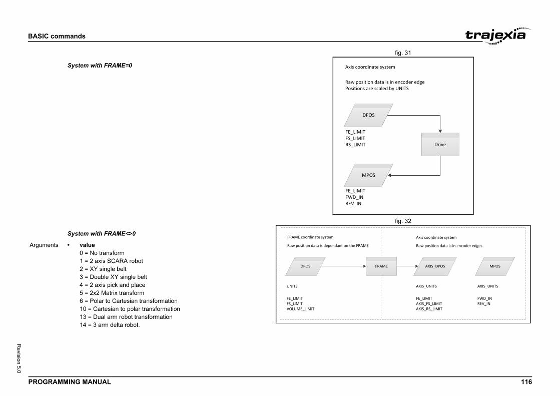
BASIC
PROG 116
Revision 5.0
fig. 31/i
fig. 32/iFRAM
Drive
system
ta is in encoder edgealed by UNITS
AXIS_DPOSAME MPOS
FE_LIMITAXIS_FS_LIMITAXIS_RS_LIMIT
AXIS_UNITS
FWD_INREV_IN
AXIS_UNITS
Axis coordinate system
Raw position data is in encoder edgesArgum
commands
RAMMING MANUAL
E2
DPOS
MPOS
Axis coordinate
Raw position daPositions are sc
FE_LIMITFS_LIMITRS_LIMIT
FE_LIMITFWD_INREV_IN
System with FRAME=0
DPOS FR
FRAME coordinate system
Raw position data is dependant on the FRAME
FE_LIMITFS_LIMITVOLUME_LIMIT
UNITS
System with FRAME<>0
ents • value0 = No transform1 = 2 axis SCARA robot2 = XY single belt3 = Double XY single belt4 = 2 axis pick and place5 = 2x2 Matrix transform6 = Polar to Cartesian transformation10 = Cartesian to polar transformation13 = Dual arm robot transformation14 = 3 arm delta robot.
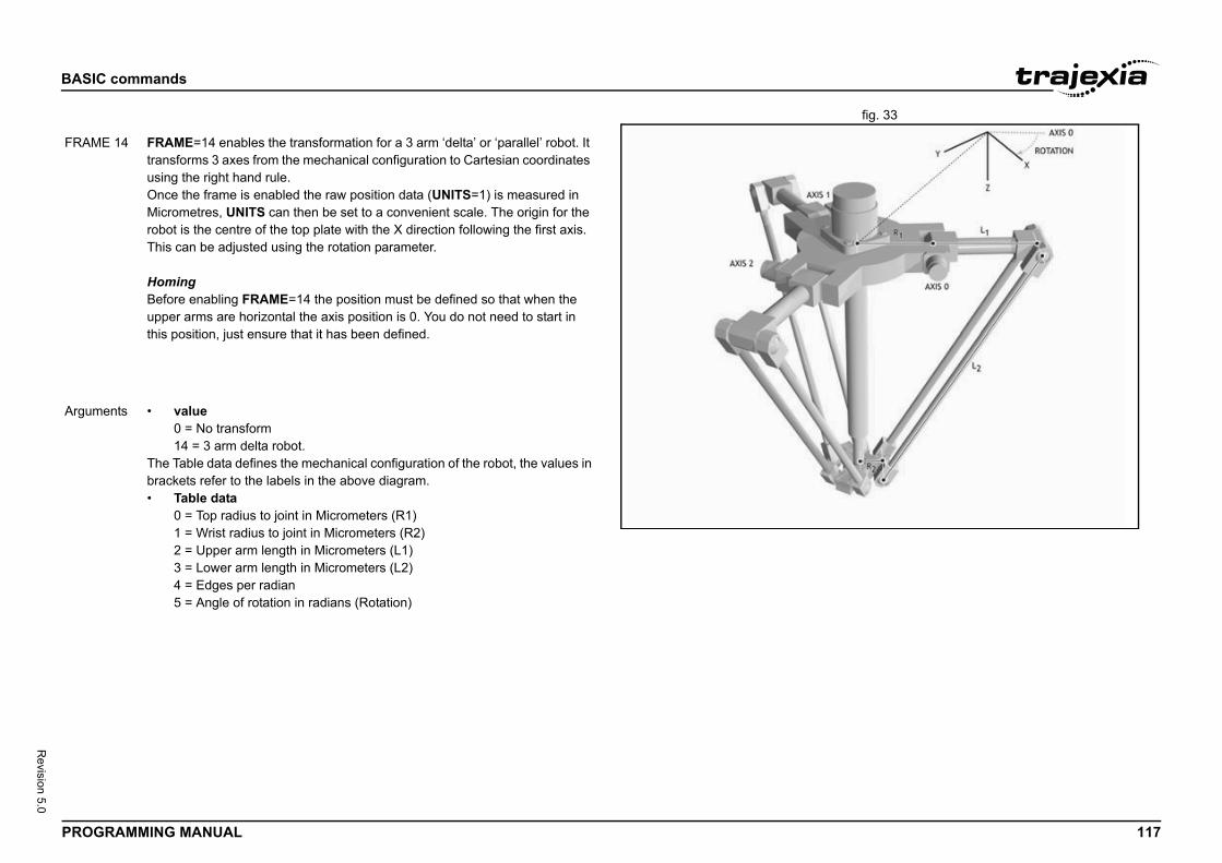
BASIC
PROG 117
Revision 5.0
fig. 33/iAME2
FRAM
Argum
commands
RAMMING MANUAL
E 14 FRAME=14 enables the transformation for a 3 arm ‘delta’ or ‘parallel’ robot. It transforms 3 axes from the mechanical configuration to Cartesian coordinates using the right hand rule.Once the frame is enabled the raw position data (UNITS=1) is measured in Micrometres, UNITS can then be set to a convenient scale. The origin for the robot is the centre of the top plate with the X direction following the first axis. This can be adjusted using the rotation parameter.
HomingBefore enabling FRAME=14 the position must be defined so that when the upper arms are horizontal the axis position is 0. You do not need to start in this position, just ensure that it has been defined.
ents • value0 = No transform14 = 3 arm delta robot.
The Table data defines the mechanical configuration of the robot, the values in brackets refer to the labels in the above diagram.• Table data
0 = Top radius to joint in Micrometers (R1)1 = Wrist radius to joint in Micrometers (R2)2 = Upper arm length in Micrometers (L1)3 = Lower arm length in Micrometers (L2)4 = Edges per radian5 = Angle of rotation in radians (Rotation)
BASIC
PROG 118
Revision 5.0
Exam '''''''''''''''''''''''''''''''''e frame'''''''''''''''''''''''''''''''''rizontal in home positionitialised.0 TO 2
SER_FRAME
oup, [table_offset, [axis0, axis1 …axisn]])
used to define the group of axes and the table offset FRAME or USER_FRAME transformation. There are eaning that you can run a maximum of 8 FRAMEs on the
can be initialised on a controller it may not be possible to en SERVO_PERIOD. The number that can be run ctors including, which FRAME is selected, drive connec-_FRAME and TOOL_OFFSET are enabled and addi-nications.
in the group must match the number of axes used by the ust also be ascending order though they do not have to
roup is deleted FRAME and USER_FRAME are set to 0
d compatibility if the FRAME command is used on an roup, or no groups are configured then a default group is est axes and table_offset=0.
AME_GROUP(0) is already configured it is overwritten.
commands
RAMMING MANUAL
3.2.151 FRAME_GROUP/i
ple Start-up sequence for a 3 arm delta robot using the default FRAME_GROUP. Homing is completed using a sensor that detects when the upper arms are level.'''''''''''''''''''''''''''''''''''''''''''''''''''''''''''''''''''''''' Define Link Lengths for 3 arm delta:'''''''''''''''''''''''''''''''''''''''''''''''''''''''''''''''''''''''TABLE(0,200000)' Top radius to jointTABLE(1,50000)' Wrist radius to jointTABLE(2,320000)' Upper arm lengthTABLE(3,850000)' Lower arm length'''''''''''''''''''''''''''''''''''''''''''''''''''''''''''''''''''''''' Define encoder edges/radian''''''''''''''''''''''''''''''''''''''''''''''''''''''''''''''''''''''''18bit encoder and 31:1 ratio gearboxresolution = 262144 * 31 / (2 * PI)TABLE(4,resolution)'''''''''''''''''''''''''''''''''''''''''''''''''''''''''''''''''''''''' Define rotation of robot relative to global frame'''''''''''''''''''''''''''''''''''''''''''''''''''''''''''''''''''''''rotation = 30 'degreesTABLE(5, (rotation*2*PI )/360)'''''''''''''''''''''''''''''''''''''''''''''''''''''''''''''''''''''''' Configure axis'''''''''''''''''''''''''''''''''''''''''''''''''''''''''''''''''''''''FOR axis_number=0 TO 2BASE(axis_number)'World coordinate system to operate in mmUNITS=1000SERVO=ONNEXT axis_numberWDOG=ONBASE(0)
''''''''''''''''''''''''''''''''''''''' Home and initialis'''''''''''''''''''''''''''''''''''''''Arms MUST be ho' before frame is inFOR axis_number=DATUM(4)WAIT IDLENEXT axis_number'Enable FrameFRAME=14
See also FRAME_GROUP, U
Type System command
Syntax FRAME_GROUP(gr
Description FRAME_GROUP is which are used in a 8 groups available mcontroller.Warning:Although 8 FRAMEsprocess all 8 at a givdepends on many fation method, if USERtional factory commuThe number of axesFRAME. The axes mbe contiguous. If a gfor those axes.To maintain backwaraxis that is not in a gcreated using the lowIn this situation if FR
BASIC
PROG 119
Revision 5.0
Argum
Exam
See a
commands
RAMMING MANUAL
ents • groupThe group number, 0-7. When used as the only parameter FRAME_GROUP prints the FRAME_GROUP, the active USER_FRAME and TOOL_OFFSET information to the currently selected output channel (default channel 0)
• table_offset-1 = Delete group data0+ = The start position in the table to store the FRAME configuration.
• axis0The first axis in the group
• axis1The second axis in the group
• axis nThe last axis in the group
ple Configure a FRAME_GROUP for axes 1,2 and 5 using table offset 100.'Initialise the FRAME_GROUPFRAME_GROUP(0,100, 1,2,5)'Configure the axes, FRAME table data and home the robotGOSUB configure_frame'PRINT the FRAME_GROUP information to the command lineFRAME_GROUP(0)'Enable the frameFRAME AXIS(1)=14
lso FRAME, USER_FRAME
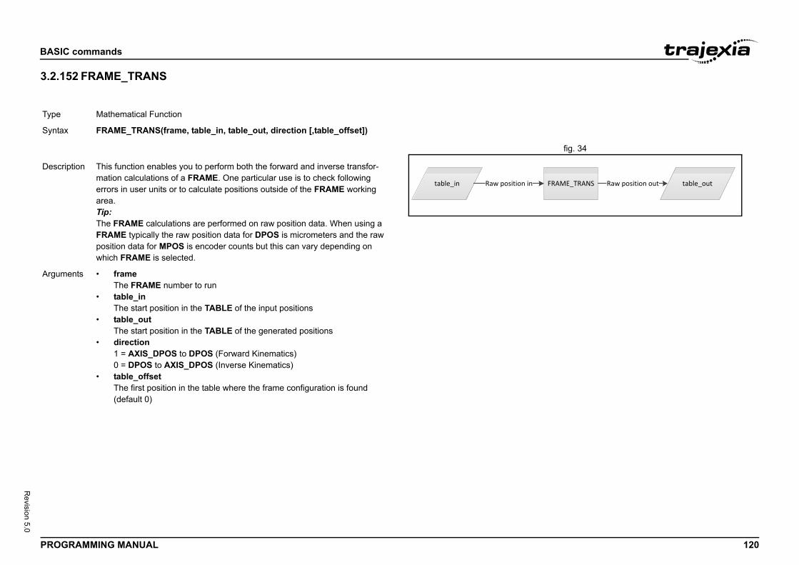
BASIC
PROG 120
Revision 5.0
3.2.1/i
fig. 34/i
Type
Synta
table_outFRAME_TRANS Raw position out
Descr
Argum
commands
RAMMING MANUAL
52 FRAME_TRANS
Mathematical Function
x FRAME_TRANS(frame, table_in, table_out, direction [,table_offset])
table_in Raw position in
iption This function enables you to perform both the forward and inverse transfor-mation calculations of a FRAME. One particular use is to check following errors in user units or to calculate positions outside of the FRAME working area.Tip:The FRAME calculations are performed on raw position data. When using a FRAME typically the raw position data for DPOS is micrometers and the raw position data for MPOS is encoder counts but this can vary depending on which FRAME is selected.
ents • frameThe FRAME number to run
• table_inThe start position in the TABLE of the input positions
• table_outThe start position in the TABLE of the generated positions
• direction1 = AXIS_DPOS to DPOS (Forward Kinematics)0 = DPOS to AXIS_DPOS (Inverse Kinematics)
• table_offsetThe first position in the table where the frame configuration is found (default 0)
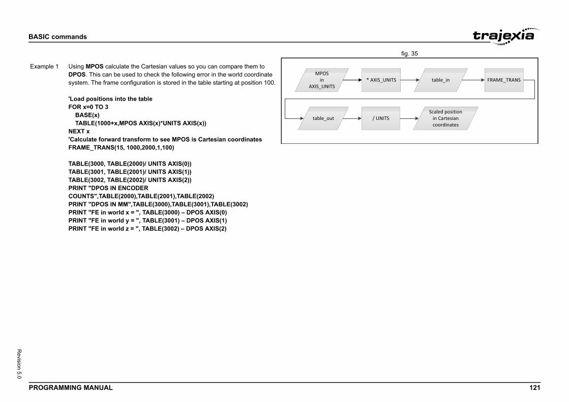
BASIC
PROG 121
Revision 5.0
fig. 35/i
table_inNITS FRAME_TRANS
TSScaled position
in Cartesian coordinates
Exam
commands
RAMMING MANUAL
MPOSin
AXIS_UNITS* AXIS_U
table_out / UNI
ple 1 Using MPOS calculate the Cartesian values so you can compare them to DPOS. This can be used to check the following error in the world coordinate system. The frame configuration is stored in the table starting at position 100. 'Load positions into the tableFOR x=0 TO 3 BASE(x) TABLE(1000+x,MPOS AXIS(x)*UNITS AXIS(x))NEXT x'Calculate forward transform to see MPOS is Cartesian coordinatesFRAME_TRANS(15, 1000,2000,1,100)
TABLE(3000, TABLE(2000)/ UNITS AXIS(0))TABLE(3001, TABLE(2001)/ UNITS AXIS(1))TABLE(3002, TABLE(2002)/ UNITS AXIS(2))PRINT "DPOS IN ENCODER COUNTS",TABLE(2000),TABLE(2001),TABLE(2002)PRINT "DPOS IN MM",TABLE(3000),TABLE(3001),TABLE(3002)PRINT "FE in world x = ", TABLE(3000) – DPOS AXIS(0)PRINT "FE in world y = ", TABLE(3001) – DPOS AXIS(1)PRINT "FE in world z = ", TABLE(3002) – DPOS AXIS(2)
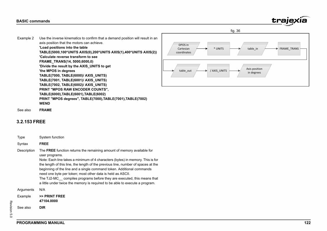
BASIC
PROG 122
Revision 5.0
fig. 36/i
3.2.1/i
table_inS FRAME_TRANS
NITS Axis positionin degrees
Exam
See a
Type
Synta
Descr
Argum
Exam
See a
commands
RAMMING MANUAL
53 FREE
DPOS in Cartesian
coordinates* UNIT
table_out / AXIS_U
ple 2 Use the inverse kinematics to confirm that a demand position will result in an axis position that the motors can achieve.'Load positions into the tableTABLE(5000,100*UNITS AXIS(0),200*UNITS AXIS(1),400*UNITS AXIS(2))'Calculate reverse transform to seeFRAME_TRANS(14, 5000,6000,0)'Divide the result by the AXIS_UNITS to get'the MPOS in degreesTABLE(7000, TABLE(6000)/ AXIS_UNITS)TABLE(7001, TABLE(6001)/ AXIS_UNITS)TABLE(7002, TABLE(6002)/ AXIS_UNITS)PRINT "MPOS RAW ENCODER COUNTS", TABLE(6000),TABLE(6001),TABLE(6002)PRINT "MPOS degrees", TABLE(7000),TABLE(7001),TABLE(7002)WEND
lso FRAME
System function
x FREE
iption The FREE function returns the remaining amount of memory available for user programs.Note: Each line takes a minimum of 4 characters (bytes) in memory. This is for the length of this line, the length of the previous line, number of spaces at the beginning of the line and a single command token. Additional commands need one byte per token; most other data is held as ASCII.The TJ2-MC__ compiles programs before they are executed, this means that a little under twice the memory is required to be able to execute a program.
ents N/A
ple >> PRINT FREE47104.0000
lso DIR
BASIC
PROG 123
Revision 5.0
3.2.1/i
Type
Synta
Descr
Argum
Exam
See a
commands
RAMMING MANUAL
54 FS_LIMIT
Axis parameter
x FS_LIMITFSLIMIT
iption The FS_LIMIT axis parameter contains the absolute position of the forward software limit in user units.A software limit for forward movement can be set from the program to control the working range of the machine. When the limit is reached, the TJ2-MC__ will ramp down the speed of an axis to 0, and then cancel the move. Bit 9 of the AXISSTATUS axis parameter will be turned on while the axis position is greater than FS_LIMIT.FS_LIMIT is disabled when it has a value greater than REP_DIST.
ents N/A
ple No example.
lso AXIS, AXIS_FS_LIMIT, REP_DIST, UNIT_INIT.
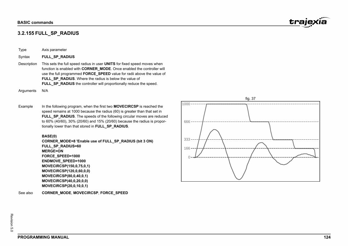
BASIC
PROG 124
Revision 5.0
3.2.1/i
fig. 37/i
Type
Synta
Descr
Argum
Exam
See a
commands
RAMMING MANUAL
55 FULL_SP_RADIUS
Axis parameter
x FULL_SP_RADIUS
iption This sets the full speed radius in user UNITS for fixed speed moves when function is enabled with CORNER_MODE. Once enabled the controller will use the full programmed FORCE_SPEED value for radii above the value of FULL_SP_RADIUS. Where the radius is below the value of FULL_SP_RADIUS the controller will proportionally reduce the speed.
ents N/A
0
1000
666
333
166
ple In the following program, when the first two MOVECIRCSP is reached the speed remains at 1000 because the radius (60) is greater than that set in FULL_SP_RADIUS. The speeds of the following circular moves are reduced to 60% (40/60), 30% (20/60) and 15% (20/60) because the radius is propor-tionally lower than that stored in FULL_SP_RADIUS.
BASE(0)CORNER_MODE=8 'Enable use of FULL_SP_RADIUS (bit 3 ON)FULL_SP_RADIUS=60MERGE=ONFORCE_SPEED=1000ENDMOVE_SPEED=1000MOVECIRCSP(150,0,75,0,1)MOVECIRCSP(120,0,60,0,0)MOVECIRCSP(80,0,40,0,1)MOVECIRCSP(40,0,20,0,0)MOVECIRCSP(20,0,10,0,1)
lso CORNER_MODE, MOVECIRCSP, FORCE_SPEED
BASIC
PROG 125
Revision 5.0
3.2.1/i
3.2.1/i
Type
Synta
Descr
Argum
Exam
See a
Type
Synta
Descr
Argum
Exam
See a
mand
assigns the ASCII code of a received character to a varia-buffer is empty, program execution will be paused until a eceived. Channels 5 to 7 are logical channels that are programming port 0 when using Trajexia Studio.served for the connection to Trajexia Studio and/or the ce. Please be aware that this channel may give problems
put device. When this argument is omitted, the port as EVICE will be used. See the table below.
n
ng port 0
erial port 1
85 serial port 2
dio port 0 user channel 5
dio port 0 user channel 6
dio port 0 user channel 7
variable to receive the ASCII code.
SCII character received on the Trajexia Studio port chan-
EY, LINPUT
commands
RAMMING MANUAL
56 FWD_IN
57 FWD_JOG
3.2.158 GET/i
/i
/i
Axis parameter
x FWD_IN
iption The FWD_IN axis parameter contains the input number to be used as a for-ward limit input. The valid input range is 0 to 31. Values 0 to 15 represent physically present inputs of TJ2-MC__ I/O connector and are common for all axes.Values 16 to 31 are mapped directly to Drive inputs that are present on the CN1 connector. They are unique for each axis. It depends on the type of Servo Drive which Servo Drive inputs are mapped into inputs 16 to 31.As default the parameter is set to -1, no inputs selected.If an input number is set and the limit is reached, any forward motion on that axis will be stopped. Bit 4 of the AXISSTATUS will also be set.Note: This input is active low.
ents N/A
ple No example.
lso AXIS, AXIS_FS_LIMIT, REV_IN.
Axis parameter
x FWD_JOG
iption The FWD_JOG axis parameter contains the input number to be used as a jog forward input. The input can be set from 0 to 31. As default the parameter is set to -1, no input is selected.Note: This input is active low.
ents N/A
ple No example.
lso AXIS, FAST_JOG, JOGSPEED, REV_JOG.
Type Communication com
Syntax GET [#n,] variable
Description The GET command ble. If the serial port character has been rsuperimposed on theNote: Channel 0 is recommand line interfafor this function.
Arguments • nThe specified inspecified by IND
Input device num-ber
Descriptio
0 Programmi
1 RS-232C s
2 RS-422A/4
5 Trajexia Stu
6 Trajexia Stu
7 Trajexia Stu
• variableThe name of the
Example GET#5, kThis line stores the Anel 5 in k.
See also INDEVICE, INPUT, K
BASIC
PROG 126
Revision 5.0
3.2.1/i
Type
Synta
Descr
Argum
Exam
See a
mand
re enables a subroutine jump. GOSUB stores the position OSUB command and then jumps to the specified label. ETURN statement, program execution is returned to the
each task can be nested up to 8 levels deep.
t occurs in the program. An invalid label will give a compi-re execution.haracter strings of any length, but only the first 15 charac-nt. Alternatively line numbers may be used as labels.
position=";MPOS;CHR(13);
mand
enables a jump of program execution. GOTO jumps pro-e line of the program containing the label.
commands
RAMMING MANUAL
59 GLOBAL 3.2.160 GOSUB..RETURN/i
3.2.161 GOTO/i
System command
x GLOBAL ["name"[, vr_number]]
iption Declares the name as a reference to one of the global VR varia-bles. The name can then be used both within the program contain-ing the GLOBAL definition and all other programs in the Trajexia Studio project.Note: The program containing the GLOBAL definition must be run before the name is used in other programs. In addition, only that program should be running at the time the GLOBAL is executed, otherwise the program error will appear and the program will stop when trying to execute this command. For fast startup the program should also be the only process running at power-up.Using GLOBAL with only the name will erase the specified global variable. Using GLOBAL with no parameters will erase all GLOBAL declarations. This also happens when the TJ2-MC__ is reset by switching the power off and back on, or by executing the EX command.In programs that use the defined GLOBAL, name has the same meaning as VR(vr_number). Do not use the syntax: VR(name).A maximum of 1024 GLOBALs can be declared.The maximum length of the name of the GLOBAL is 32 characters.
ents • nameAny user-defined name containing lower case alpha, numeri-cal or underscore characters.
• vr_numberThe number of the VR to be associated with name.
ple GLOBAL "srew_pitch",12GLOBAL "ratio1",534ratio1 = 3.56screw_pitch = 23.0PRINT screw_pitch, ratio1
lso LIST_GLOBAL
Type Program control com
Syntax GOSUB label...RETURN
Description The GOSUB structuof the line after the GUpon reaching the Rstored position.Note: Subroutines on
Arguments • labelA valid label thalation error befoLabels can be cters are significa
Example main: GOSUB routine GOTO mainroutine: PRINT "Measured RETURN
See also GOTO
Type Program control com
Syntax GOTO label
Description The GOTO structuregram execution to th
BASIC
PROG 127
Revision 5.0
3.2.1/i
3.2.1/i
Argum
Exam
See a
Type
Synta
Descr
Argum
Exam
See a
Type
Synta
Descr
Argum
16))
mand
ommand, port [ , node [ , mc_area/mode [ , mc_offset
D command performs a specific Host link command o all Host Link Slaves on the selected port.ill be paused until the response string has been received as elapsed. The timeout time is specified by using the ameter. The status of the transfer can be monitored with arameter.
HLM_COMMAND, be sure to set-up the Host Link Mas-sing the SETCOM command.aster commands are required to be executed from one ly to avoid any multi-task timing problems.
the Host Link operation to perform. See the table below.
e Host Link PLC MODEL READ (MM) command to read del code. The result is written to the TJ2-MC__ variable area and mc_offset.
e Host Link TEST (TS) command to check correct com-nding string "MC__ TEST STRING" and checking the heck the HLM_STATUS parameter for the result.
e Host Link ABORT (XZ) command to abort the Host link currently being processed. The ABORT command does ponse.
commands
RAMMING MANUAL
62 HALT
63 HEX
3.2.164 HLM_COMMAND/i
/i
ents • labelA valid label that occurs in the program. An invalid label will give a compi-lation error before execution.Labels can be character strings of any length, but only the first 15 char-acters are significant. Alternatively line numbers may be used as labels.
ple loop: PRINT "Measured position = ";MPOS;CHR(13); WA(1000)GOTO loop
lso GOSUB..RETURN
System command
x HALT
iption The HALT command stops execution of all program tasks currently running. The command can be used both on Command Line Terminal as in programs. The STOP command can be used to stop a single program task.Note: HALT doesn’t stop any motion. Currently executing, or buffered moves will continue unless they are terminated with a CANCEL or RAPIDSTOP com-mand.
ents N/A
ple No example.
lso PROCESS, STOP.
System command
x HEX
iption This command is used in a print statement to output a number in hexadecimal format.
ents N/A
Example PRINT#5,HEX(IN(8,
See also N/A
Type Communication com
Syntax HLM_COMMAND(c]]])
Description The HLM_COMMANoperation to one or tProgram execution wor the timeout time hHLM_TIMEOUT parthe HLM_STATUS pNotes:• When using the
ter protocol by u• The Host Link M
program task on
Arguments • commandThe selection of
command value Description
HLM_MREAD(or value 0)
This performs ththe CPU Unit mospecified by mc_
HLM_TEST(or value 1)
This performs thmunication by seechoed string. C
HLM_ABORT(or value 2)
This performs thcommand that isnot receive a res
BASIC
PROG 128
Revision 5.0
/i
/i
/i
HLM_(or va
HLM_(or va
mc_a
MC_T(or va
MC_V(or va
comm LM_MREAD,1,12,MC_VR,233) the CPU Unit model code of the Host Link Slave with nected to the RS-232C port. The result is written to
e is a any OMRON CJ/CS PLC model, the VR(233) will x) after successful execution.
LM_TEST,2,23)S PORT(2)heck the Host Link communication with the Host Link nected to the RS-422A port. parameter contains value 0, the communication is func-
LM_INIT,2)LM_ABORT,2,4)s perform the Host Link INITIALIZE and ABORT opera- port 2. The Slave has node number 4.
LM_STWR,2,0,2) written to a PC using Host Link, the CPU Unit can not be LM_COMMAND command can be used to set it to e Slave has node address 0 and is connected to the
TATUS, HLM_TIMEOUT, HLS_NODE, HLM_WRITE,
commands
RAMMING MANUAL
INITlue 3)
This performs the Host Link INITIALIZE (**) command to initialize the transmission control procedure of all Slave Units.
STWRlue 4)
This performs the Host Link STATUS WRITE (SC) command to change the operating mode of the CPU Unit.
• portThe specified serial port. 1 = RS-232C serial port 1; 2 = RS-422A serial port 2.
• node (for HLM_MREAD, HLM_TEST, HLM_ABORT and HLM_STWR)The Slave node number to send the Host link command to. Range: [0, 31].
• mode (for HLM_STWR)The specified CPU Unit operating mode. 0 = PROGRAM mode; 2 = MONITOR mode; 3 = RUN mode.
• mc_area (for HLM_MREAD)The memory selection of the TJ2-MC__ to read the send data from. See the table below.
rea value Data area
ABLElue 8)
TABLE variable array
Rlue 9)
Global (VR) variable array
• mc_offset (for HLM_MREAD)The address of the specified TJ2-MC__ memory area to read from. Range for VR variables: [0, 1023]. Range for TABLE variables: [0, 63999].
and value Description Example HLM_COMMAND(HThis command readsnode address 12 conVR(233).If the connected Slavcontain value 30 (he
Example HLM_COMMAND(HPRINT HLM_STATUThis command will cSlave (node 23) conIf the HLM_STATUStional.
Example HLM_COMMAND(HHLM_COMMAND(HThese two commandtions on the RS-422A
Example HLM_COMMAND(HWhen data has to bein RUN mode. The HMONITOR mode. ThRS-232C port.
See also HLM_READ, HLM_SSETCOM.
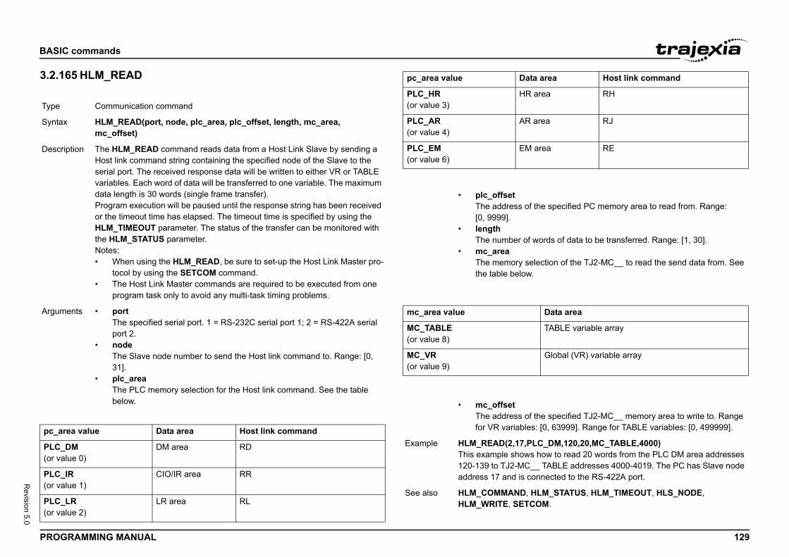
BASIC
PROG 129
Revision 5.0
3.2.1/i
/i
Type
Synta
Descr
Argum
pc_a
PLC_(or va
PLC_(or va
PLC_(or va
area RH
area RJ
area RE
the specified PC memory area to read from. Range:
ords of data to be transferred. Range: [1, 30].
lection of the TJ2-MC__ to read the send data from. See
Data area
TABLE variable array
Global (VR) variable array
the specified TJ2-MC__ memory area to write to. Range : [0, 63999]. Range for TABLE variables: [0, 499999].
C_DM,120,20,MC_TABLE,4000) how to read 20 words from the PLC DM area addresses _ TABLE addresses 4000-4019. The PC has Slave node nnected to the RS-422A port.
LM_STATUS, HLM_TIMEOUT, HLS_NODE, OM.
area Host link command
commands
RAMMING MANUAL
65 HLM_READ
/i
/i
/i
Communication command
x HLM_READ(port, node, plc_area, plc_offset, length, mc_area, mc_offset)
iption The HLM_READ command reads data from a Host Link Slave by sending a Host link command string containing the specified node of the Slave to the serial port. The received response data will be written to either VR or TABLE variables. Each word of data will be transferred to one variable. The maximum data length is 30 words (single frame transfer).Program execution will be paused until the response string has been received or the timeout time has elapsed. The timeout time is specified by using the HLM_TIMEOUT parameter. The status of the transfer can be monitored with the HLM_STATUS parameter.Notes:• When using the HLM_READ, be sure to set-up the Host Link Master pro-
tocol by using the SETCOM command.• The Host Link Master commands are required to be executed from one
program task only to avoid any multi-task timing problems.
ents • portThe specified serial port. 1 = RS-232C serial port 1; 2 = RS-422A serial port 2.
• nodeThe Slave node number to send the Host link command to. Range: [0, 31].
• plc_areaThe PLC memory selection for the Host link command. See the table below.
rea value Data area Host link command
DMlue 0)
DM area RD
IRlue 1)
CIO/IR area RR
LRlue 2)
LR area RL
PLC_HR(or value 3)
HR
PLC_AR(or value 4)
AR
PLC_EM(or value 6)
EM
• plc_offsetThe address of [0, 9999].
• lengthThe number of w
• mc_areaThe memory sethe table below.
mc_area value
MC_TABLE(or value 8)
MC_VR(or value 9)
• mc_offsetThe address of for VR variables
Example HLM_READ(2,17,PLThis example shows120-139 to TJ2-MC_address 17 and is co
See also HLM_COMMAND, HHLM_WRITE, SETC
pc_area value Data
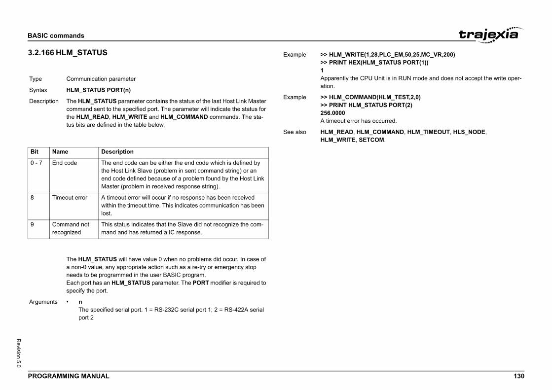
BASIC
PROG 130
Revision 5.0
3.2.1/i
/i
/i
Type
Synta
Descr
Bit
0 - 7
8
9
Argum
8,PLC_EM,50,25,MC_VR,200)_STATUS PORT(1))
Unit is in RUN mode and does not accept the write oper-
(HLM_TEST,2,0)TUS PORT(2)
ccurred.
OMMAND, HLM_TIMEOUT, HLS_NODE, OM.
commands
RAMMING MANUAL
66 HLM_STATUS
Communication parameter
x HLM_STATUS PORT(n)
iption The HLM_STATUS parameter contains the status of the last Host Link Master command sent to the specified port. The parameter will indicate the status for the HLM_READ, HLM_WRITE and HLM_COMMAND commands. The sta-tus bits are defined in the table below.
Name Description
End code The end code can be either the end code which is defined by the Host Link Slave (problem in sent command string) or an end code defined because of a problem found by the Host Link Master (problem in received response string).
Timeout error A timeout error will occur if no response has been received within the timeout time. This indicates communication has been lost.
Command not recognized
This status indicates that the Slave did not recognize the com-mand and has returned a IC response.
The HLM_STATUS will have value 0 when no problems did occur. In case of a non-0 value, any appropriate action such as a re-try or emergency stop needs to be programmed in the user BASIC program.Each port has an HLM_STATUS parameter. The PORT modifier is required to specify the port.
ents • nThe specified serial port. 1 = RS-232C serial port 1; 2 = RS-422A serial port 2
Example >> HLM_WRITE(1,2>> PRINT HEX(HLM1Apparently the CPU ation.
Example >> HLM_COMMAND>> PRINT HLM_STA256.0000A timeout error has o
See also HLM_READ, HLM_CHLM_WRITE, SETC
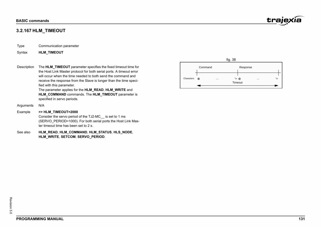
BASIC
PROG 131
Revision 5.0
3.2.1/i
fig. 38/i
Type
Synta
Response
Timeout
Descr
Argum
Exam
See a
commands
RAMMING MANUAL
67 HLM_TIMEOUT
Communication parameter
x HLM_TIMEOUT
Command
Characters
iption The HLM_TIMEOUT parameter specifies the fixed timeout time for the Host Link Master protocol for both serial ports. A timeout error will occur when the time needed to both send the command and receive the response from the Slave is longer than the time speci-fied with this parameter.The parameter applies for the HLM_READ, HLM_WRITE and HLM_COMMAND commands. The HLM_TIMEOUT parameter is specified in servo periods.
ents N/A
ple >> HLM_TIMEOUT=2000Consider the servo period of the TJ2-MC__ is set to 1 ms (SERVO_PERIOD=1000). For both serial ports the Host Link Mas-ter timeout time has been set to 2 s.
lso HLM_READ, HLM_COMMAND, HLM_STATUS, HLS_NODE, HLM_WRITE, SETCOM, SERVO_PERIOD.
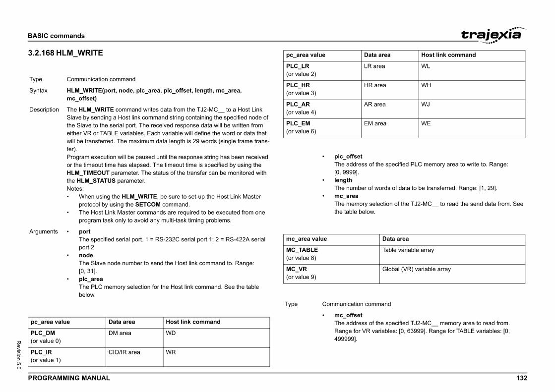
BASIC
PROG 132
Revision 5.0
3.2.1/i
/i
Type
Synta
Descr
Argum
pc_a
PLC_(or va
PLC_(or va
rea WL
rea WH
rea WJ
rea WE
the specified PLC memory area to write to. Range:
ords of data to be transferred. Range: [1, 29].
lection of the TJ2-MC__ to read the send data from. See
Data area
Table variable array
Global (VR) variable array
mand
the specified TJ2-MC__ memory area to read from. ariables: [0, 63999]. Range for TABLE variables: [0,
area Host link command
commands
RAMMING MANUAL
68 HLM_WRITE
/i
/i
/i
Communication command
x HLM_WRITE(port, node, plc_area, plc_offset, length, mc_area, mc_offset)
iption The HLM_WRITE command writes data from the TJ2-MC__ to a Host Link Slave by sending a Host link command string containing the specified node of the Slave to the serial port. The received response data will be written from either VR or TABLE variables. Each variable will define the word or data that will be transferred. The maximum data length is 29 words (single frame trans-fer).Program execution will be paused until the response string has been received or the timeout time has elapsed. The timeout time is specified by using the HLM_TIMEOUT parameter. The status of the transfer can be monitored with the HLM_STATUS parameter.Notes:• When using the HLM_WRITE, be sure to set-up the Host Link Master
protocol by using the SETCOM command.• The Host Link Master commands are required to be executed from one
program task only to avoid any multi-task timing problems.
ents • portThe specified serial port. 1 = RS-232C serial port 1; 2 = RS-422A serial port 2
• nodeThe Slave node number to send the Host link command to. Range: [0, 31].
• plc_areaThe PLC memory selection for the Host link command. See the table below.
rea value Data area Host link command
DMlue 0)
DM area WD
IRlue 1)
CIO/IR area WR
PLC_LR(or value 2)
LR a
PLC_HR(or value 3)
HR a
PLC_AR(or value 4)
AR a
PLC_EM(or value 6)
EM a
• plc_offsetThe address of [0, 9999].
• lengthThe number of w
• mc_areaThe memory sethe table below.
mc_area value
MC_TABLE(or value 8)
MC_VR(or value 9)
Type Communication com
• mc_offsetThe address of Range for VR v499999].
pc_area value Data
BASIC
PROG 133
Revision 5.0
3.2.1/i
3.2.1/i
Exam
See a
Type
Synta
Descr
Argum
Exam
See a
Type
Synta
command turns on the OUT 0 output for the axis when easured position is reached, and turns the output off red position is reached. Positions are defined as LE memory in range from table_start, to table_end, and W_PSWITCH command are stored in FIFO queue.
plicable only to Flexible axis axes with ATYPE values 43,
e used with either 1 or 5 parameters. Only 1 parameter is e switch or clear FIFO queue. All five parameters are itch.nd going through the sequence of positions in it, if the to be executed again, FIFO must be cleared before exe-H command with the same parameters.
ch; 1 = on and load FIFO; 2 = clear FIFO.
1 = increasing.
set in the first position in the FIFO; ON or OFF.
address of the sequence.
ddress of the sequence.
ON, 21, 50)ad FIFO with 30 positions, stored in TABLE memory (21) in increasing direction. When the position stored in d, the OUT 0 output will be set ON and then alternatively hing following positions in the sequence, until the posi-(50) reached.
isable switch if it was enabled previously, but will not clear
lear FIFO queue if loaded previously.
commands
RAMMING MANUAL
69 HLS_NODE
70 HW_PSWITCH
ple HLM_WRITE(1,28,PLC_EM,50,25,MC_VR,200)This example shows how to write 25 words from TJ2-MC__ ' s VR addresses 200-224 to the PC EM area addresses 50-74. The PC has Slave node address 28 and is connected to the RS-232C port.
lso HLM_READ, HLM_COMMAND, HLM_STATUS, HLM_TIMEOUT, HLS_NODE, SETCOM.
Communication parameter
x HLS_NODE
iption The HLS_NODE parameter defines the Slave unit number for the Host Link Slave protocol. The TJ2-MC__ will only respond as a Host Link Slave to Host Link Master command strings with the unit number as specified in this param-eter. The valid range for this parameter is [0, 31]. The default value is 0.
ents N/A
ple No example.
lso N/A
I/O command
x HW_PSWITCH(mode, direction, opstate, table_start, table_end)
Description The HW_PSWITCH the predefined axis mwhen another measusequence in the TABon execution of the HThis command is ap44, 45 and 60.The command can bneeded to disable thneeded to enable swAfter loading FIFO asame sequence hascuting HW_PSWITC
Arguments • mode0 = disable swit
• direction0 = decreasing;
• opstateOutput state to
• table_startStarting TABLE
• table_endEnding TABLE a
Example HW_PSWITCH(1, 1,This command will lostarting from TABLETABLE(21) is reacheOFF and ON on reaction stored in TABLE
Example HW_PSWITCH(0)This command will dthe FIFO queue.
Example HW_PSWITCH(2)This command will c
See also AXIS
BASIC
PROG 134
Revision 5.0
3.2.1/i
3.2.1
See W
3.2.1/i
Type
Synta
Descr
Argum
Exam
See a
Type
Synta
Descr
of 8 bit values that represents a valid IEEE floating point
0,b1,b2,b3)
n
(value, n)
tion returns a single byte in IEEE format extracted from ue for transmission over a communications link. The be called 4 times to extract each byte in turn.igh byte of the 32 bit IEEE floating point format.
ting point variable or parameter.
r (0 - 3) to be extracted.
a, 0)a, 1)a, 2)a, 3)
commands
RAMMING MANUAL
71 I_GAIN
72 IDLE
AIT IDLE.
73 IEEE_IN
3.2.174 IEEE_OUT/i
Axis parameter
x I_GAIN
iption The I_GAIN parameter contains the integral gain for the axis. The integral out-put contribution is calculated by multiplying the sums of the Following Errors with the value of the I_GAIN parameter. The default value is 0.Adding integral gain to a servo system reduces positioning error when at rest or moving steadily, but it can produce or increase overshooting and oscillation and is therefore only suitable for systems working on constant speed and with slow accelerations.Note: In order to avoid any instability the servo gains should be changed only when the SERVO is off.Note: Servo gains have no affect on stepper output axis (ATYPE=46), MECHATROLINK-II position axis (ATYPE=40), EtherCAT position axis (ATYPE=65) or Accurax G5-A/P position axis (ATYPE=80).
ents N/A
ple No example.
lso D_GAIN, OV_GAIN, P_GAIN, VFF_GAIN.
Mathematical function
x IEEE_IN(byte0,byte1,byte2,byte3)
iption The IEEE_IN function returns the floating point number represented by 4 bytes which typically have been received over a communications link, such as ModbusTCP or FINS.Note: byte0 is the high byte of the 32 bit IEEE floating point format.
Arguments • byte0 - byte3Any combinationnumber.
Example VR(20) = IEEE_IN(b
See also N/A
Type Mathematical functio
Syntax byte_n = IEEE_OUT
Description The IEEE_OUT functhe floating point valfunction will typicallyNote: Byte 0 is the h
Arguments • valueAny BASIC floa
• nThe byte numbe
Example a=MPOS AXIS(2)byte0 = IEEE_OUT(byte1 = IEEE_OUT(byte2 = IEEE_OUT(byte3 = IEEE_OUT(
See also N/A
BASIC
PROG 135
Revision 5.0
3.2.1/i
Type
Synta
Descr
Argum
Exam
Exam
Exam
EN
32 THEN
33 THEN
unknown"
,final_input_number ])]
ns the value of digital inputs. binary sum of the first 32 inputs.er, final_input_number) will return the binary sum of uts in range [input_number, final_input_number]. The must be less than 32 apart.er) will return the value of the particular input specified r input_number.
he input for which to return a value. The range for this nds on the number of additional digital I/O connected ATROLINK-II or EtherCAT network. If there are no digital he range for this parameter is 0..31.mberhe last input for which to return a value. The range for epends on the number of additional digital I/O connected
ATROLINK-II or EtherCAT network. If there are no digital he range for this parameter is 0..31
commands
RAMMING MANUAL
75 IF..THEN..ELSE..ENDIF
3.2.176 IN/i
Program control command
x IF condition_1 THEN commands {ELSEIF condition_i THEN commands} [ ELSE commands ] ENDIFIF condition_1 THEN commands
iption This structure controls the flow of the program based on the results of the con-dition. If the condition is TRUE the commands following THEN up to ELSEIF, ELSE or ENDIF are executed. If the condition is FALSE and the command of a subsequent ELSEIF substructure is TRUE, the commands of this substruc-ture are executed. If all conditions are FALSE the commands following ELSE will be executed or the program will resume at the line after ENDIF in case no ELSE is included. The ENDIF is used to mark the end of the conditional block.Note: IF..THEN..ELSE..ENDIF sequences can be nested without limit. For a multi-line IF..THEN construction, there must not be any statement after THEN. A single-line construction must not use ENDIF.
ents • condition_iA logical expression.
• commandsOne or more BASIC commands.
ple IF MPOS > (0.22 * VR(0)) THEN GOTO exceeds_length
ple IF IN(0) = ON THEN count = count + 1 PRINT "COUNTS = ";count fail = 0ELSE fail = fail + 1ENDIF
ple IF IN(stop)=ON THEN OP(8,ON) VR(cycle_flag)=0ELSEIF IN(start_cycle)=ON THEN VR(cycle_flag)=1ELSEIF IN(step1)=ON THEN VR(cycle_flag)=99ENDIF
Example IF key_char=$31 TH GOSUB char_1ELSEIF key_char=$ GOSUB char_2ELSEIF key_char=$ GOSUB char_3ELSE PRINT "CharacterENDIF
See also N/A
Type I/O function
Syntax IN[(input_number [IN
Description The IN function retur• IN will return the• IN(input_numb
the group of inptwo arguments
• IN(input_numbby the paramete
Arguments • input_numberThe number of tparameter depeover the MECHI/O connected, t
• final_ input_nuThe number of tthis parameter dover the MECHI/O connected, t
BASIC
PROG 136
Revision 5.0
3.2.1/i
Exam
Exam
See a
Type
Synta
Descr
Argum
iables with an include program.
nitions_DEFS”
using defined varsive_axis)axis) AXIS(link_axis)
AL_DEFS”:
meter
meter defines the default input device. This device will be t commands when the #n option is omitted. The r is task specific. The supported values are listed in the
ault)
2
r channel 5
r channel 6
r channel 7
commands
RAMMING MANUAL
77 INCLUDE
3.2.178 INDEVICE/i
/i
ple The following lines can be used to move to the position set on a thumb wheel multiplied by a factor. The thumb wheel is connected to inputs 4, 5, 6 and 7, and gives output in BCD.moveloop: MOVEABS(IN(4,7)*1.5467) WAIT IDLE GOTO moveloopThe MOVEABS command is constructed as follows:Step 1: IN(4,7) will get a number between 0 and 15.Step 2: The number is multiplied by 1.5467 to get required distance.Step 3: An absolute move is made to this position.
ple In this example a single input is tested:test: WAIT UNTIL IN(4)=ON ' Conveyor is in position when ON GOSUB place
lso OP.
System command
x INITIALISE “file_name”
iption The INCLUDE command resolves all local variable definitions in the included file at compile time and allows all the local variables to be declared “globally”.Note:Whenever an included program is modified, all programs that depend on it are re-compiled as well, avoiding inconsistency.(1) Nested INCLUDEs are not allowed.(2) The INCLUDE command must be the first BASIC statement in the pro-gram.(3) Only variable definitions are allowed in the include file. It cannot be usedas a general subroutine with any other BASIC commands in it.
ents • file_nameThe name of the program to be included.
Example Initialise all local varPROGRAM “T1”:'include global defiINCLUDE “GLOBAL'Motion commandsFORWARD AXIS(drCONNECT(1, drive_
PROGRAM “GLOBdrive_axis=4link_axis=1
See also N/A.
Type Communication para
Syntax INDEVICE
Description The INDEVICE paraselected for the inpuINDEVICE parametetable below.
Value Description
0 Programming port 0 (def
1 RS-232C serial port 1
2 RS-422A/485 serial port
5 Trajexia Studio port 0 use
6 Trajexia Studio port 0 use
7 Trajexia Studio port 0 use
BASIC
PROG 137
Revision 5.0
/i
3.2.1/i
3.2.1/i
Argum
Exam
See a
Type
Synta
Descr
Argum
Exam
See a
Type
Synta
Descr
eing the 64 bit value to read.riable_low the lower 32 bits of the source variable to..riable_high the lower 32 bits of the source variable to..
(MOTION_ERROR,VR(100),VR(101))py the first 32 bits of MOTION_ERROR to VR(100)01).
des the axis from the interpolated motion calculations so following axis. This means that you can create an inter-h z completing its movement over the same time period. ed is calculated using any axes that have nabled. This means that at least one axis must be ena-ance in the motion command otherwise the calculated d the command will complete immediately with no move-
nly operates with MOVE, MOVEABS and MHELICAL uding the SP versions. All other motion commands axes and so ignore this parameter.
commands
RAMMING MANUAL
79 INITIALISE
80 INTEGER_READ
3.2.181 INTERP_FACTOR/i
ents N/A
ple No example.
lso GET, INPUT, LINPUT, KEY.
System command
x INITIALISE
iption Sets all axes parameters to their default values. The parameters are also reset each time the controller is powered up, or when an EX (software reset) command is performed. In Trajexia Studio the menu Reset Device under the Online menu performs the equivalent of an EX command.
ents N/A
ple No example.
lso EX.
System command
x INTEGER_READ(source_variable, destination_variable_low,destination_variable_high)
iption The INTEGER_READ command splits a 64 bit variable in 2 32 bit valuesand copies these values to 2 other variables. The source and destinationvariables can be any valid system, named, TABLE memory or VRvariable.The following parameters are 64 bit integers: MOTION_ERROR, TICKS, DEMAND_EDGES, TRANS_DPOS.
Arguments • source_variablVariable contain
• destination_vaVariable to copy
• destination_vaVariable to copy
Example >> INTEGER_READThis example will coand the rest to VR(1
See also MOTION_ERROR
Type Axis Parameter
Syntax INTERP_FACTOR
Description This parameter excluthat it will become a polated x,y move witThe interpolated speINTERP_FACTOR ebled and have a distspeed will be zero anment.INTERP_FACTOR o(on the 3rd axis) inclrequire interpolated
Arguments
BASIC
PROG 138
Revision 5.0
3.2.1/i
Exam
See a
Type
Synta
Descr
Argum
g program to receive data from the terminal.
COUNT=";num[0] on the terminal could be:
3
PUT, KEY
n
rns the integer part of the expression.itive number to the nearest integer value take the INT
added by 0.5. Similarly, to round for a negative value lue before applying INT.
expression.
n/off)
mand allows the input channels 0..31 to be individually This is important as these input channels can be functions such as feedhold.tion sets the inversion for one channel ON or OFF. It can
puts 0..31.
commands
RAMMING MANUAL
82 INPUT
3.2.183 INT/i
3.2.184 INVERT_IN/i
ple It is required to move a ‘z’ axis interpolated with x and y however we want the interpolated speed to only be active on the x,y move. We disable the z axis from the interpolation group using INTERP_FACTOR. Remember when the movement is complete you must enable INTERP_FACTOR again.BASE(2)INTERP_FACTOR=0'Perform movementBASE(0,1,2)MOVEABS(x_offset, y_offset, z_offset)WAIT IDLEINTERP_FACTOR AXIS(12) = 1
lso N/A
Communication command
x INPUT [ #n ], variable { , variable }
iption The INPUT command will assign numerical input string values to the specified variables. Multiple input string values can be requested on one line, sepa-rated by commas, or on multiple lines separated by carriage return. The pro-gram execution will be paused until the string is terminated with a carriage return after the last variable has been assigned.If the string is invalid, the user will be prompted with an error message and the task will be repeated. The maximum amount of inputs on one line has no limit other than the line length.Channels 5 to 7 are logical channels that are superimposed on the program-ming port 0 when using Trajexia Studio.Note: Channel 0 is reserved for the connection to Trajexia Studio and/or the Command Line Terminal interface. Please be aware that this channel may give problems for this function.
ents • nThe specified input device. When this argument is omitted, the port as specified by INDEVICE will be used.
• variableThe variable to write to.
Example Consider the followinINPUT#5, numPRINT#5, "BATCH A possible response123<CR>BATCH COUNT=12
See also INDEVICE, GET, LIN
Type Mathematical functio
Syntax INT(expression)
Description The INT function retuNote: To round a posfunction of the valuesubtract 0.5 to the va
Arguments • expressionAny valid BASIC
Example >> PRINT INT(1.79)1.0000
See also N/A
Type System command
Syntax INVERT_IN(input, o
Description The INVERT_IN cominverted in software.assigned to activate The INVERT_IN funconly be applied to in
BASIC
PROG 139
Revision 5.0
3.2.1/i
AND
Argum
Exam
Exam
See a
Type
Synta
Descr
Argum
ND(module, station, 1, alarm_number)ND(module, station, 7, operation_signals)ND(module, station, 8, mode)
ND controls inputs and clears alarm of the Inverter con- via the MECHATROLINK-II bus.RTER_COMMAND functions:
rm.ation signals.r to Servo Drive mode, so it acts as a servo axis. This is
r Inverters with an encoder feedback option card con-
a MECHATROLINK-II you must put the command and munication option:
N3=3; N4=9B1-01=3; B1-02=3.A1000: b1-01=3; b1-02=3.001=4; A002=4.01=5; A002=5.
verter firmware supports the MECHATROLINK-II board.s -1 if successfully executed and 0 if failed.o the Inverter corresponds with the bits given in the table
commands
RAMMING MANUAL
85 INVERT_STEP
3.2.186 INVERTER_COMM/i
ents • inputAny valid BASIC expression
ple >>? IN(3)0.0000>>INVERT_IN(3,ON)>>? IN(3)1.0000
ple Typical setting when POT and NOT inputs of the Servo Drive are also used for limits in Trajexia:BASE(base_axis)FWD_IN=16INVERT_IN(16,ON)REV_IN=17INVERT_IN(17,ON)And configure the POT and NOT inputs of the Servo Drive as required via Servo Drive parameters.
lso N/A
Axis parameter
x INVERT_STEP
iption INVERT_STEP is used to switch a signal inverter into the stepper pulse out-put circuit. This can be necessary for connecting to some stepper Drives. The electronic logic inside the Trajexia stepper pulse generator assumes that the FALLING edge of the step output is the active edge which results in motor movement. This is suitable for the majority of stepper Drives. Setting INVERT_STEP=ON effectively makes the RISING edge of the step signal the active edge. INVERT_STEP should be set if required prior to enabling the controller with WDOG=ON. Default is off.Note: If the setting is incorrect a stepper motor may lose position by one step when changing direction.Note: This parameter is applicable only to Flexible axis stepper output axes with ATYPE=46. With other types of axes, this parameter has no effect.
ents N/A
Example No example.
See also N/A
Type System command
Syntax INVERTER_COMMAINVERTER_COMMAINVERTER_COMMA
Description INVERTER_COMMAnected to the systemThere are three INVE• 1: Clears an ala• 7: Controls oper• 8: Set an Inverte
possible only fonected.
To use an Inverter vithe reference via com• Inverter MV/V7:• Inverter F7/G7: • Inverter V1000/• Inverter MX2: A• Inverter RX: A0
Make sure that the InThe command returnThe command sent tbelow.
BASIC
PROG 140
Revision 5.0
/i
/i
Bit
0
1
2
3
4
5
6
7
8
9
10
11
12
13
14
15
he TJ1-ML__ that the Inverter is connected to.
OLINK-II station number of the Inverter.
he alarm. See the Inverter manual.alsto control the operation signals. See the table below.
t the Inverter to:e. This is the default value at power-up.
mode.
E(1,$23,2,4500)MAND(1,$23,7,2)
MAND(1,$23,7,0) controls an Inverter connected via MECHATROLINK-II
it at slot 1 and with station number 23 (hex), using follow-
nce is set to 45.00 Hz.is set to run in reverse direction for 10 seconds with ined in previous step.is stopped.
odule, station, 0, param_number, param_size, VR [,
odule, station, 1, alarm_number, VR)odule, station, 2, VR)odule, station, 3, VR)odule, station, 4, from, length, VR)
commands
RAMMING MANUAL
3.2.187 INVERTER_READ/i
Value Command Description
MV/V7/F7 G7 V1000 A1000 MX2
Hex 1 Run forward
Hex 2 Run reverse
Hex 4 Input 3 Input S1 Input 1
Hex 8 Input 4 Input S2 Input 2
Hex 10 Input 5 Input S3 Input 3
Hex 20 Input 6 Input S4 Input 4
Hex 40 Input 7 Input S5 Input 5
Hex 80 NA Input 8 Input S6 Input 6
Hex 100 External fault
Hex 200 Fault reset
Hex 400 NA Input 9 NA Input S7 Input 7
Hex 800 NA Input 10 NA Input S8 NA
Hex 1000 NA Input 11 NA NA NA
Hex 2000 NA Input 12 NA NA NA
Hex 4000 Fault history data clear
Hex 8000 External BB command NA
If with function 8 the mode parameter is set to 1, the Inverter is set into servo axis mode. The corresponding axis number is assigned by the TJ2-MC__ using the formula: AxisNo = MECHATROLINK-II Station Number - 0x21 + AXIS_OFFSETTherefore the calculated AxisNo must not be occupied by another axis con-nected.
If with function 8 the mode parameter is set to 0, which is the default value at power-up, the Inverter is set into normal Inverter mode.
Arguments • moduleThe number of t
• stationThe MECHATR
• alarm_numberThe number of t
• operation_signA bitwise value
• modeThe mode to se0 = Inverter mod1 = Servo Drive
Example >>INVERTER_WRIT>>INVERTER_COM>>WA(10000)>>INVERTER_COMThe sequence abovebus to TJ1-ML__ uning steps:Step 1: Speed refereStep 2: The Inverter speed reference defStep 3: The Inverter
See also N/A
Type System command
Syntax INVERTER_READ(mvr_mode])INVERTER_READ(mINVERTER_READ(mINVERTER_READ(mINVERTER_READ(m
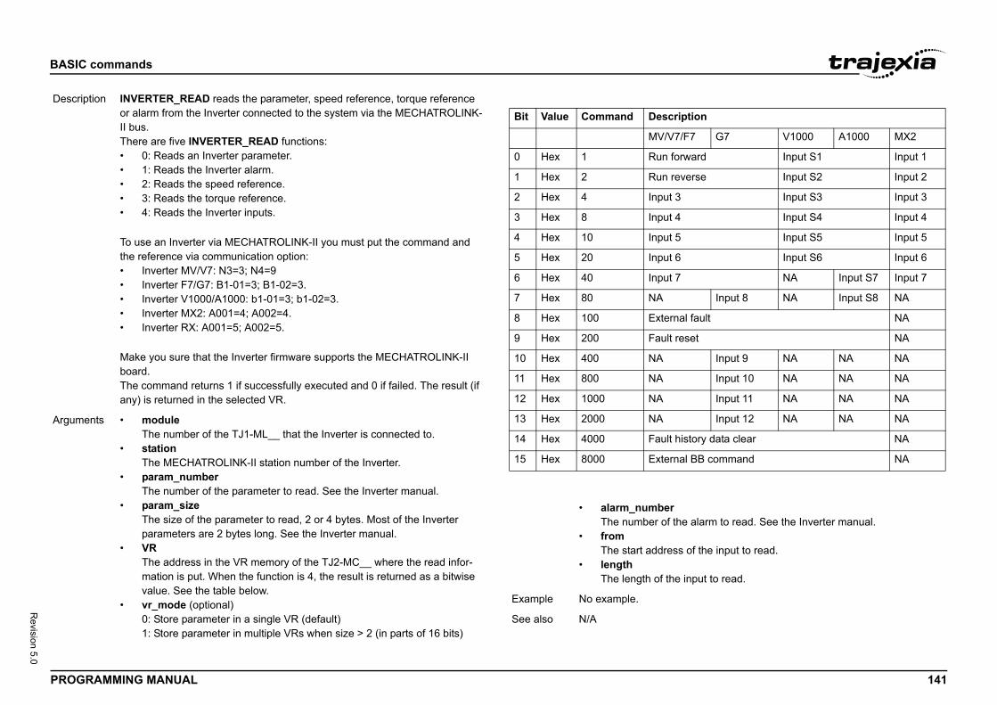
BASIC
PROG 141
Revision 5.0
Descr
Argum
ription
7/F7 G7 V1000 A1000 MX2
orward Input S1 Input 1
everse Input S2 Input 2
3 Input S3 Input 3
4 Input S4 Input 4
5 Input S5 Input 5
6 Input S6 Input 6
7 NA Input S7 Input 7
Input 8 NA Input S8 NA
nal fault NA
reset NA
Input 9 NA NA NA
Input 10 NA NA NA
Input 11 NA NA NA
Input 12 NA NA NA
history data clear NA
nal BB command NA
he alarm to read. See the Inverter manual.
s of the input to read.
e input to read.
commands
RAMMING MANUAL
/i
/i
iption INVERTER_READ reads the parameter, speed reference, torque reference or alarm from the Inverter connected to the system via the MECHATROLINK-II bus.There are five INVERTER_READ functions:• 0: Reads an Inverter parameter.• 1: Reads the Inverter alarm.• 2: Reads the speed reference.• 3: Reads the torque reference.• 4: Reads the Inverter inputs.
To use an Inverter via MECHATROLINK-II you must put the command and the reference via communication option:• Inverter MV/V7: N3=3; N4=9• Inverter F7/G7: B1-01=3; B1-02=3.• Inverter V1000/A1000: b1-01=3; b1-02=3.• Inverter MX2: A001=4; A002=4.• Inverter RX: A001=5; A002=5.
Make you sure that the Inverter firmware supports the MECHATROLINK-II board.The command returns 1 if successfully executed and 0 if failed. The result (if any) is returned in the selected VR.
ents • moduleThe number of the TJ1-ML__ that the Inverter is connected to.
• stationThe MECHATROLINK-II station number of the Inverter.
• param_numberThe number of the parameter to read. See the Inverter manual.
• param_sizeThe size of the parameter to read, 2 or 4 bytes. Most of the Inverter parameters are 2 bytes long. See the Inverter manual.
• VRThe address in the VR memory of the TJ2-MC__ where the read infor-mation is put. When the function is 4, the result is returned as a bitwise value. See the table below.
• vr_mode (optional)0: Store parameter in a single VR (default) 1: Store parameter in multiple VRs when size > 2 (in parts of 16 bits)
Bit Value Command Desc
MV/V
0 Hex 1 Run f
1 Hex 2 Run r
2 Hex 4 Input
3 Hex 8 Input
4 Hex 10 Input
5 Hex 20 Input
6 Hex 40 Input
7 Hex 80 NA
8 Hex 100 Exter
9 Hex 200 Fault
10 Hex 400 NA
11 Hex 800 NA
12 Hex 1000 NA
13 Hex 2000 NA
14 Hex 4000 Fault
15 Hex 8000 Exter
• alarm_numberThe number of t
• fromThe start addres
• lengthThe length of th
Example No example.
See also N/A
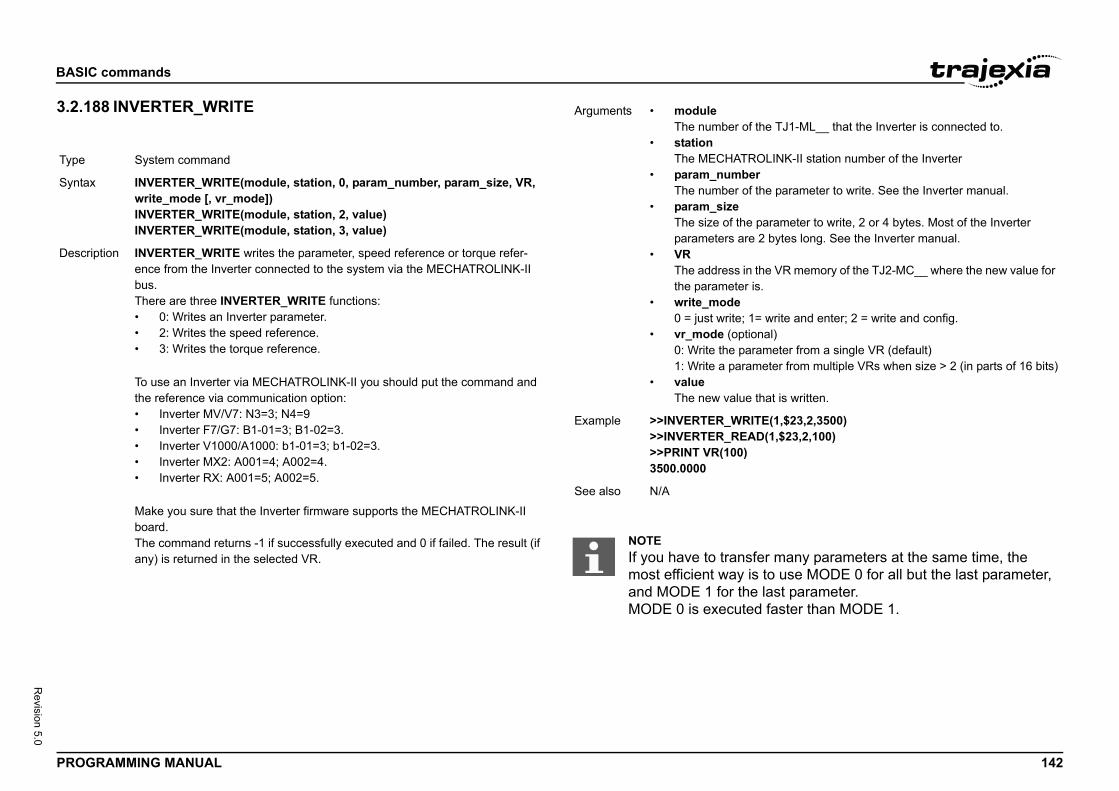
BASIC
PROG 142
Revision 5.0
3.2.1/i
Type
Synta
Descr
he TJ1-ML__ that the Inverter is connected to.
OLINK-II station number of the Inverterrhe parameter to write. See the Inverter manual.
parameter to write, 2 or 4 bytes. Most of the Inverter 2 bytes long. See the Inverter manual.
he VR memory of the TJ2-MC__ where the new value for .
write and enter; 2 = write and config.nal)ameter from a single VR (default) eter from multiple VRs when size > 2 (in parts of 16 bits)
hat is written.
E(1,$23,2,3500)D(1,$23,2,100)
er many parameters at the same time, the to use MODE 0 for all but the last parameter, last parameter. faster than MODE 1.
commands
RAMMING MANUAL
88 INVERTER_WRITE
System command
x INVERTER_WRITE(module, station, 0, param_number, param_size, VR, write_mode [, vr_mode])INVERTER_WRITE(module, station, 2, value)INVERTER_WRITE(module, station, 3, value)
iption INVERTER_WRITE writes the parameter, speed reference or torque refer-ence from the Inverter connected to the system via the MECHATROLINK-II bus.There are three INVERTER_WRITE functions:• 0: Writes an Inverter parameter.• 2: Writes the speed reference.• 3: Writes the torque reference.
To use an Inverter via MECHATROLINK-II you should put the command and the reference via communication option:• Inverter MV/V7: N3=3; N4=9• Inverter F7/G7: B1-01=3; B1-02=3.• Inverter V1000/A1000: b1-01=3; b1-02=3.• Inverter MX2: A001=4; A002=4.• Inverter RX: A001=5; A002=5.
Make you sure that the Inverter firmware supports the MECHATROLINK-II board.The command returns -1 if successfully executed and 0 if failed. The result (if any) is returned in the selected VR.
Arguments • moduleThe number of t
• stationThe MECHATR
• param_numbeThe number of t
• param_sizeThe size of the parameters are
• VRThe address in tthe parameter is
• write_mode0 = just write; 1=
• vr_mode (optio0: Write the par1: Write a param
• valueThe new value t
Example >>INVERTER_WRIT>>INVERTER_REA>>PRINT VR(100)3500.0000
See also N/A
NOTEIf you have to transfmost efficient way isand MODE 1 for theMODE 0 is executed
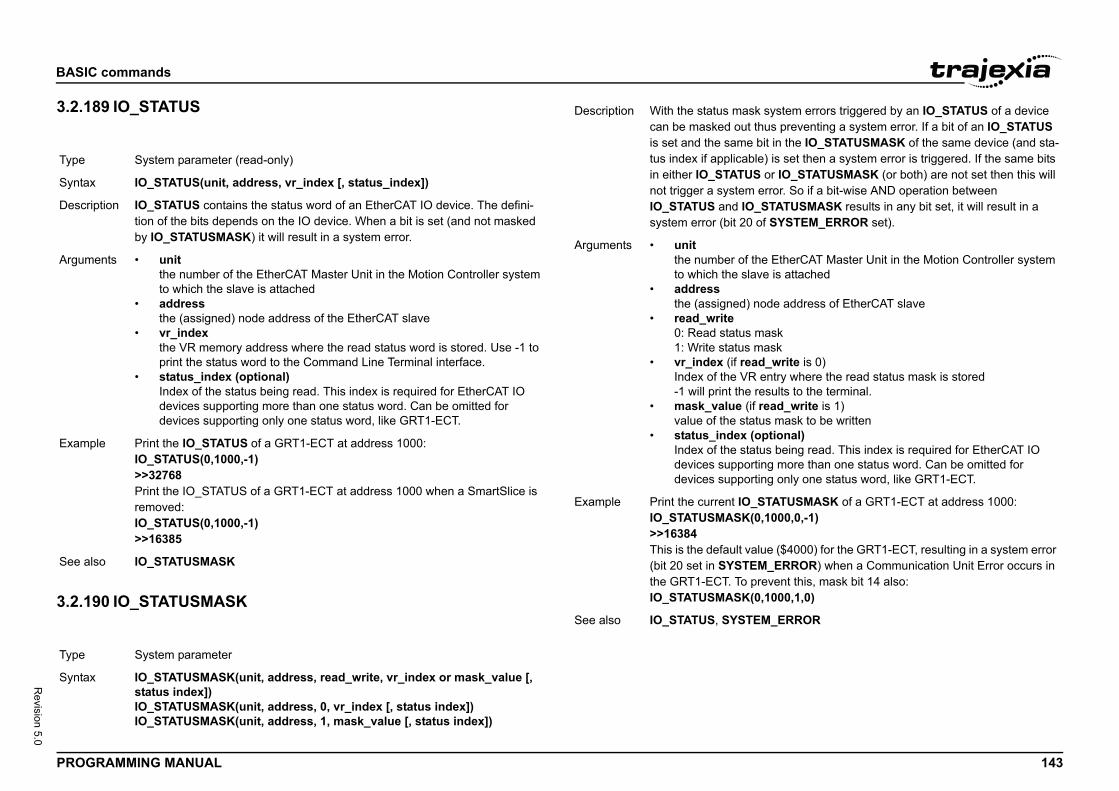
BASIC
PROG 143
Revision 5.0
3.2.1/i
3.2.1/i
Type
Synta
Descr
Argum
Exam
See a
Type
Synta
system errors triggered by an IO_STATUS of a device hus preventing a system error. If a bit of an IO_STATUS bit in the IO_STATUSMASK of the same device (and sta-e) is set then a system error is triggered. If the same bits or IO_STATUSMASK (or both) are not set then this will error. So if a bit-wise AND operation between STATUSMASK results in any bit set, it will result in a
of SYSTEM_ERROR set).
e EtherCAT Master Unit in the Motion Controller system ve is attached
ode address of EtherCAT slave
ask ask
d_write is 0) entry where the read status mask is storedesults to the terminal.read_write is 1)us mask to be writtenptional)
tus being read. This index is required for EtherCAT IO ing more than one status word. Can be omitted for ing only one status word, like GRT1-ECT.
STATUSMASK of a GRT1-ECT at address 1000:,1000,0,-1)
lue ($4000) for the GRT1-ECT, resulting in a system error M_ERROR) when a Communication Unit Error occurs in revent this, mask bit 14 also:,1000,1,0)
M_ERROR
commands
RAMMING MANUAL
89 IO_STATUS
90 IO_STATUSMASK
System parameter (read-only)
x IO_STATUS(unit, address, vr_index [, status_index])
iption IO_STATUS contains the status word of an EtherCAT IO device. The defini-tion of the bits depends on the IO device. When a bit is set (and not masked by IO_STATUSMASK) it will result in a system error.
ents • unitthe number of the EtherCAT Master Unit in the Motion Controller system to which the slave is attached
• addressthe (assigned) node address of the EtherCAT slave
• vr_indexthe VR memory address where the read status word is stored. Use -1 to print the status word to the Command Line Terminal interface.
• status_index (optional)Index of the status being read. This index is required for EtherCAT IO devices supporting more than one status word. Can be omitted for devices supporting only one status word, like GRT1-ECT.
ple Print the IO_STATUS of a GRT1-ECT at address 1000:IO_STATUS(0,1000,-1)>>32768Print the IO_STATUS of a GRT1-ECT at address 1000 when a SmartSlice is removed:IO_STATUS(0,1000,-1)>>16385
lso IO_STATUSMASK
System parameter
x IO_STATUSMASK(unit, address, read_write, vr_index or mask_value [, status index])IO_STATUSMASK(unit, address, 0, vr_index [, status index])IO_STATUSMASK(unit, address, 1, mask_value [, status index])
Description With the status maskcan be masked out tis set and the same tus index if applicablin either IO_STATUSnot trigger a system IO_STATUS and IO_system error (bit 20
Arguments • unitthe number of thto which the sla
• addressthe (assigned) n
• read_write0: Read status m1: Write status m
• vr_index (if reaIndex of the VR-1 will print the r
• mask_value (if value of the stat
• status_index (oIndex of the stadevices supportdevices support
Example Print the current IO_IO_STATUSMASK(0>>16384This is the default va(bit 20 set in SYSTEthe GRT1-ECT. To pIO_STATUSMASK(0
See also IO_STATUS, SYSTE
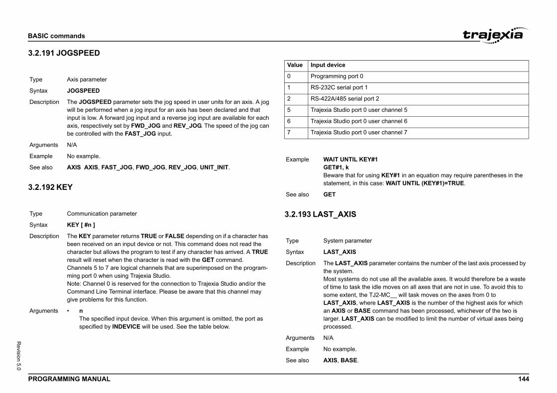
BASIC
PROG 144
Revision 5.0
3.2.1/i
3.2.1/i
Type
Synta
Descr
Argum
Exam
See a
Type
Synta
Descr
Argum
r channel 5
r channel 6
r channel 7
g KEY#1 in an equation may require parentheses in the se: WAIT UNTIL (KEY#1)=TRUE.
ameter contains the number of the last axis processed by
t use all the available axes. It would therefore be a waste le moves on all axes that are not in use. To avoid this to -MC__ will task moves on the axes from 0 to
LAST_AXIS is the number of the highest axis for which mmand has been processed, whichever of the two is an be modified to limit the number of virtual axes being
commands
RAMMING MANUAL
91 JOGSPEED
92 KEY
/i
/i
3.2.193 LAST_AXIS/i
Axis parameter
x JOGSPEED
iption The JOGSPEED parameter sets the jog speed in user units for an axis. A jog will be performed when a jog input for an axis has been declared and that input is low. A forward jog input and a reverse jog input are available for each axis, respectively set by FWD_JOG and REV_JOG. The speed of the jog can be controlled with the FAST_JOG input.
ents N/A
ple No example.
lso AXIS AXIS, FAST_JOG, FWD_JOG, REV_JOG, UNIT_INIT.
Communication parameter
x KEY [ #n ]
iption The KEY parameter returns TRUE or FALSE depending on if a character has been received on an input device or not. This command does not read the character but allows the program to test if any character has arrived. A TRUE result will reset when the character is read with the GET command.Channels 5 to 7 are logical channels that are superimposed on the program-ming port 0 when using Trajexia Studio.Note: Channel 0 is reserved for the connection to Trajexia Studio and/or the Command Line Terminal interface. Please be aware that this channel may give problems for this function.
ents • nThe specified input device. When this argument is omitted, the port as specified by INDEVICE will be used. See the table below.
Value Input device
0 Programming port 0
1 RS-232C serial port 1
2 RS-422A/485 serial port 2
5 Trajexia Studio port 0 use
6 Trajexia Studio port 0 use
7 Trajexia Studio port 0 use
Example WAIT UNTIL KEY#1GET#1, kBeware that for usinstatement, in this ca
See also GET
Type System parameter
Syntax LAST_AXIS
Description The LAST_AXIS parthe system.Most systems do noof time to task the idsome extent, the TJ2LAST_AXIS, where an AXIS or BASE colarger. LAST_AXIS cprocessed.
Arguments N/A
Example No example.
See also AXIS, BASE.
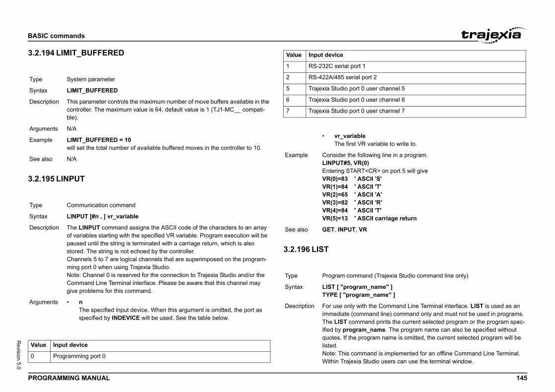
BASIC
PROG 145
Revision 5.0
3.2.1/i
3.2.1/i
/i
Type
Synta
Descr
Argum
Exam
See a
Type
Synta
Descr
Argum
Value
0
r channel 5
r channel 6
r channel 7
iable to write to.
g line in a program.
> on port 5 will give'S''T''A''R' 'T'carriage return
Trajexia Studio command line only)
me" ]ame" ]
Command Line Terminal interface. LIST is used as an d line) command only and must not be used in programs. prints the current selected program or the program spec-me. The program name can also be specified without m name is omitted, the current selected program will be
is implemented for an offline Command Line Terminal. io users can use the terminal window.
commands
RAMMING MANUAL
94 LIMIT_BUFFERED
95 LINPUT
/i
3.2.196 LIST/i
System parameter
x LIMIT_BUFFERED
iption This parameter controls the maximum number of move buffers available in the controller. The maximum value is 64, default value is 1 (TJ1-MC__ compati-ble).
ents N/A
ple LIMIT_BUFFERED = 10will set the total number of available buffered moves in the controller to 10.
lso N/A
Communication command
x LINPUT [#n , ] vr_variable
iption The LINPUT command assigns the ASCII code of the characters to an array of variables starting with the specified VR variable. Program execution will be paused until the string is terminated with a carriage return, which is also stored. The string is not echoed by the controller.Channels 5 to 7 are logical channels that are superimposed on the program-ming port 0 when using Trajexia Studio.Note: Channel 0 is reserved for the connection to Trajexia Studio and/or the Command Line Terminal interface. Please be aware that this channel may give problems for this command.
ents • nThe specified input device. When this argument is omitted, the port as specified by INDEVICE will be used. See the table below.
Input device
Programming port 0
1 RS-232C serial port 1
2 RS-422A/485 serial port 2
5 Trajexia Studio port 0 use
6 Trajexia Studio port 0 use
7 Trajexia Studio port 0 use
• vr_variableThe first VR var
Example Consider the followinLINPUT#5, VR(0)Entering START<CRVR(0)=83 ' ASCII VR(1)=84 ' ASCII VR(2)=65 ' ASCII VR(3)=82 ' ASCII VR(4)=84 ' ASCII VR(5)=13 ' ASCII
See also GET, INPUT, VR
Type Program command (
Syntax LIST [ "program_naTYPE [ "program_n
Description For use only with theimmediate (commanThe LIST command ified by program_naquotes. If the progralisted.Note: This commandWithin Trajexia Stud
Value Input device
BASIC
PROG 146
Revision 5.0
3.2.1/i
3.2.1/i
Argum
Exam
See a
Type
Synta
Descr
Argum
Exam
See a
Type
Synta
rns the natural logarithm of the expression. The input st be greater than 0.
expression.
d prevents the program from being viewed, modified or l unaware of the security code. The lock code number is ROM. The UNLOCK command allows the locked state code number can be any integer and is held in encoded s an immediate command and can be issued only when CKED. are available from within Trajexia Studio, users can
from the Online menu.
r with maximum 7 digits.
ot be modified or seen.)
unlocked.
ust be remembered; it will be required to ithout the security code the system can not
commands
RAMMING MANUAL
97 LIST_GLOBAL
98 LN
3.2.199 LOCK/i
ents • program_nameThe program to be printed.
ple No example.
lso SELECT.
System command (terminal only)
x LIST_GLOBAL
iption When executed from the Command Line Terminal interface (channel 0), all the currently set GLOBAL and CONSTANT parameters will be printed to the terminal.
ents N/A
ple In an application where the following GLOBAL and CONSTANT have been set:CONSTANT "cutter", 23GLOBAL "conveyor",5
>>LIST_GLOBAL Global VR ---------------- ---- conveyor 5 Constant Value ---------------- ------- cutter 23.0000
lso CONSTANT, GLOBAL
Mathematical function
x LN(expression)
Description The LN function retuexpression value mu
Arguments • expressionAny valid BASIC
Example >> PRINT LN(10)2.3026
See also N/A
Type System command
Syntax LOCK(code)UNLOCK(code)
Description The LOCK commandeleted by personnestored in the Flash-Pto be unlocked. The form. LOCK is alwaythe system is UNLOLOCK and UNLOCKselect Lock Device
Arguments • codeAny valid intege
Example >> LOCK(561234)The programs cann>> UNLOCK(561234The system is now
See also N/A
CAUTIONThe security code munlock the system. Wbe recovered.
BASIC
PROG 147
Revision 5.0
3.2.2/i
3.2.2/i
Type
Synta
Descr
Argum
Exam
See a
Type
Synta
Descr
Argum
Exam
See a
nit,0)s devices on MECHATROLINK-II Master Unit unit. It is reset the network from a communication problem and to have been not detected (EG: when the A letter in the becomes capital red).nit,3,VR)f detected MECHATROLINK-II devices after a it,0). It is used by the SHELL program to check that the ECHATROLINK-II stations corresponds with the expected.
nit,4,station,VR) of MECHATROLINK-II device at that “station” number. are a sequence 0..x for all the attached devices. -1 is is allocated to that station. It is used by the SHELL pro-e number of detected MECHATROLINK-II stations corre-cted.
nit,5,station,VR)issed message count. A Non-Axis MECHATROLINK-II rt automatically a network problem so, use this command
nd IO modules for checking that the network is alive.
command MECHATROLINK(unit,5,station,VR) to mon-f a device during a program execution.f the VR address is greater than 0 a communication error occurs and the device can malfunction. You can use this p your program when the device has an error.
has two forms, depending upon the function required: unctions. functions return TRUE (-1) if the command was suc-
) if the command failed.parated out into 2 types, Master functions that work on a ctions that work on a specific station_address of a given
ieve a value store it in the VR variable indicated in the parameter has the value -1 then the value is printed to rt.
commands
RAMMING MANUAL
00 MARK
01 MARKB
3.2.202 MECHATROLINK/i
Axis parameter (read-only)
x MARK
iption The MARK is set to FALSE when the REGIST command has been executed and is set to TRUE when the primary registration event occurs. Only when this parameter is TRUE, the REG_POS value is correct.
ents N/A
ple loop: WAIT UNTIL IN(punch_clr)=ON MOVE(index_length) REGIST(3) WAIT UNTIL(MARK) MOVEMODIFY(REG_POS + offset) WAIT IDLEGOTO loop
lso AXIS, REGIST, REG_POS.
Axis parameter (read-only)
x MARKB
iption The MARKB is set to FALSE when the REGIST command has been exe-cuted and is set to TRUE when the primary registration event occurs. Only when this parameter is TRUE, the REG_POSB value is correct.
ents N/A
ple IF MARKB AXIS(2) THEN PRINT "Secondary registration event for axis 2 occurred"ENDIF
lso AXIS, REGIST, REG_POSB.
Type System command
Syntax MECHATROLINK(uDetects and connectnecessary to use it tore-detect servos thatAXISSTATUS word MECHATROLINK(uReturns the number oMECHATROLINK(unnumber of detected MMECHATROLINK(uReturns the addressThe station numbersreturned if no devicegram to check that thsponds with the expeMECHATROLINK(uReads and clears mdevice does not repoto poll the Inverter aNote:• You can use the
itor the status oIf the contents owith the device command to sto
Description Note: This commandMaster and Station FAll MECHATROLINKcessful or FALSE (0The functions are seunit, and Station fununit.All functions that retrlast parameter. If thisthe command line po
BASIC
PROG 148
Revision 5.0
3.2.2/i
Argum
Exam
See a
Type
Synta
Descr
Argum
Exam
See a
nd2, centre1, centre2, direction, distance3 [,mode]))tre1, centre2, direction, distance3 [,mode])
ove, that is, moves 2 orthogonal axes in such a way as to c at the tool point with a simultaneous linear move on a parameters are similar to those of a MOVECIRC com-meter defines the simultaneous linear move.
re on the current BASE axis. end2 and centre2 are on
arameters are scaled according to the current unit con- BASE axis. The sixth parameter uses its own axis units.
E axis to finish at.
t axis in BASE array to finish at.
E axis about which to move.
t axis in BASE array about which to move.
a software switch which determines whether the arc is clockwise or anti- clockwise direction. The parameter is e MOVECIRC.
move on the third axis in the BASE array axis in user
he third axis with the main two axis when calculating path cal path).nly the first two axes for path speed, but move the third
tion with the other 2 axes (circular path with following second example below.
commands
RAMMING MANUAL
03 MERGE
3.2.204 MHELICAL/i
ents N/A
ple No example.
lso N/A
Axis parameter
x MERGE
iption The MERGE parameter is a software switch that can be used to enable or disable the merging of consecutive moves. When MERGE is ON and the next move already in the next move buffer (NTYPE), the axis will not ramp down to 0 speed but will load up the following move enabling a seamless merge. The default setting of MERGE is OFF.It is up to the programmer to ensure that merging is sensible. For example, merging a forward move with a reverse move will cause an attempted instan-taneous change of direction.MERGE will only function if the following are all true:1. Only the speed profiled moves MOVE, MOVEABS, MOVECIRC,
MHELICAL, REVERSE, FORWARD and MOVEMODIFY can be merged with each other. They cannot be merged with linked moves CONNECT, MOVELINK and CAMBOX.
2. There is a move in the next move buffer (NTYPE).3. The axis group does not change for multi-axis moves.
When merging multi-axis moves, only the base axis MERGE axis parameter needs to be set.Note: If the moves are short, a high deceleration rate must be set to avoid the TJ2-MC__ decelerating in anticipation of the end of the buffered move.
ents N/A
ple MERGE = OFF ' Decelerate at the end of each moveMERGE = ON ' Moves will be merged if possible
lso AXIS.
Type Axis command
Syntax MHELICAL(end1, eMH(end1, end2, cen
Description Performs a helical mproduce a circular arthird axis. The first 5mand. The sixth paraend1 and centre1 athe following axis.The first 4 distance pversion factor for the
Arguments • end1Position on BAS
• end2Position on nex
• centre1Position on BAS
• centre2Position on nex
• directionThe direction isinterpolated in aset to 0 or 1. Se
• distance3The distance tounits.
• mode0 = Interpolate tspeed (true heli1 = Interpolate oaxis in coordinathird axis). See
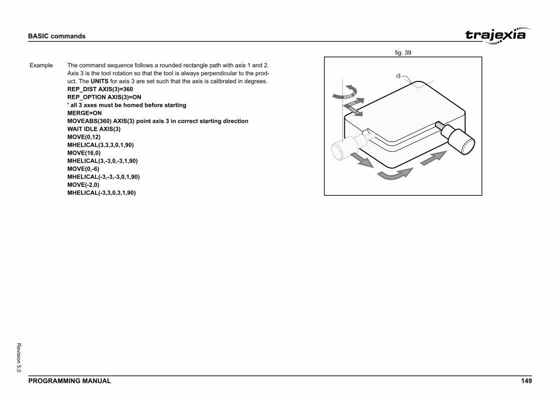
BASIC
PROG 149
Revision 5.0
fig. 39/i
r3
Exam
commands
RAMMING MANUAL
AXIS 2
AXIS 1
AXIS 0
ple The command sequence follows a rounded rectangle path with axis 1 and 2. Axis 3 is the tool rotation so that the tool is always perpendicular to the prod-uct. The UNITS for axis 3 are set such that the axis is calibrated in degrees.REP_DIST AXIS(3)=360REP_OPTION AXIS(3)=ON' all 3 axes must be homed before startingMERGE=ONMOVEABS(360) AXIS(3) point axis 3 in correct starting directionWAIT IDLE AXIS(3)MOVE(0,12)MHELICAL(3,3,3,0,1,90)MOVE(16,0)MHELICAL(3,-3,0,-3,1,90)MOVE(0,-6)MHELICAL(-3,-3,-3,0,1,90)MOVE(-2,0)MHELICAL(-3,3,0,3,1,90)
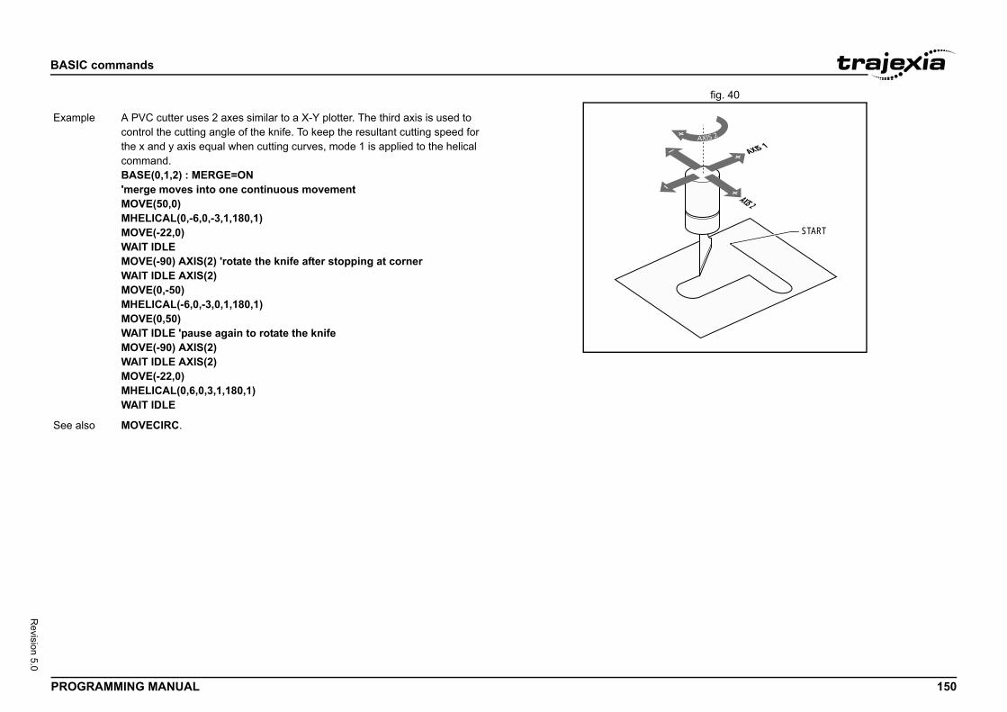
BASIC
PROG 150
Revision 5.0
fig. 40/i
START
AXIS 1
AXIS 2
Exam
See a
commands
RAMMING MANUAL
ple A PVC cutter uses 2 axes similar to a X-Y plotter. The third axis is used to control the cutting angle of the knife. To keep the resultant cutting speed for the x and y axis equal when cutting curves, mode 1 is applied to the helical command.BASE(0,1,2) : MERGE=ON'merge moves into one continuous movementMOVE(50,0)MHELICAL(0,-6,0,-3,1,180,1)MOVE(-22,0)WAIT IDLEMOVE(-90) AXIS(2) 'rotate the knife after stopping at cornerWAIT IDLE AXIS(2)MOVE(0,-50)MHELICAL(-6,0,-3,0,1,180,1)MOVE(0,50)WAIT IDLE 'pause again to rotate the knifeMOVE(-90) AXIS(2)WAIT IDLE AXIS(2)MOVE(-22,0)MHELICAL(0,6,0,3,1,180,1)WAIT IDLE
lso MOVECIRC.
BASIC
PROG 151
Revision 5.0
3.2.2/i
Type
Synta
Descr
Argum
d moves using the look ahead buffer with MERGE=ON a red where the incoming vector speed is 40 units/second tor speed is 20 units/second.
=2000,0,100,1,100)
_SPEED, ENDMOVE_SPEED
n
xpression2
turns the expression2 modulus of expression1. This integer part of any non-integer input.
expression.
expression.
13
commands
RAMMING MANUAL
05 MHELICALSP
3.2.206 MOD/i
Axis command
x MHELICALSP(end1, end2, centre1, centre2, direction, distance3 [,mode]))
iption Works as MHELICALSP and additionally allows vector speed to be changed when using multiple moves in the look ahead buffer when MERGE=ON, using additional parameters FORCE_SPEED, ENDMOVE_SPEED.When the command is loaded into the move buffer the FORCE_SPEED and ENDMOVE_SPEED parameters are copied into the buffer with the move. FORCE_SPEED defines the speed of the motion command. ENDMOVE_SPEED defines the ramp to exit speed.If two forced speed move types are merged, the speed at the merge point is controlled by the ENDMOVE_SPEED of the outgoing move. If a forced speed move follows one or more non-forced speed moves the deceleration will occur to the FORCE_SPEED of the incoming move.
ents • end1Position on BASE axis to finish at.
• end2Position on next axis in BASE array to finish at.
• centre1Position on BASE axis about which to move.
• centre2Position on next axis in BASE array about which to move.
• directionThe direction is a software switch which determines whether the arc is interpolated in a clockwise or anti- clockwise direction. The parameter is set to 0 or 1. See MOVECIRC.
• distance3The distance to move on the third axis in the BASE array axis in user units.
• mode0 = Interpolate the third axis with the main two axis when calculating path speed (true helical path).1 = Interpolate only the first two axes for path speed, but move the third axis in coordination with the other 2 axes (circular path with following third axis).
Example In a series of bufferehelical move is requiand the finishing vecFORCE_SPEED=40ENDMOVE_SPEEDMHELICALSP(100,1
See also MHELICAL, FORCE
Type Mathematical functio
Syntax expression1 MOD e
Description The MOD function refunction will take the
Arguments • expression1Any valid BASIC
• expression2Any valid BASIC
Example >> PRINT 122 MOD5.0000
See also N/A
BASIC
PROG 152
Revision 5.0
3.2.2/i
Type
Synta
Descr
Argum
Exam
See a
, distance_2 [ , distance_3 [ , distance_4 [, ...]]]])istance_2 [ , distance_3 [ , distance_4 [, ...]]]])
d moves with one or more axes at the demand speed deceleration to a position specified as increment from
In multi-axis moves the movement is interpolated and the and deceleration are taken from the base axis.ces are scaled using the unit conversion factor in the er. If, for example, an axis has 4,000 encoder edges/mm, nits for that axis would be set to 4000, and MOVE(12.5) . Note that the electronic gear ratio parameters of thesed to adjust the number of encoder pulses per lineartails see 5.1.3.
default basis axis group (set with BASE) unless AXIS is porary base axis. Argument distance_1 is applied to the 2 is applied to the next axis, etc. By changing the axis OVE commands, uninterpolated, unsynchronised multi-chieved. Incremental moves can be merged for profiled ements by turning on the MERGE axis parameter. movement, the individual speeds are calculated using Given command MOVE(x1,x2) and the profiled speed vp e SPEED, ACCEL and DECEL parameters from the tal multi-axes distance L = SQR(x1
2 + x22).
vi for axis i at any time of the movement is calculated as:
ke up to 64 arguments.
move for every axis in user units starting with the base
a unit conversion factor of 1 and has a 1000 line 1000 line encoder gives 4000 edges/turn.e 10 turns on the motor.
commands
RAMMING MANUAL
07 MOTION_ERROR 3.2.208 MOVE/i
System parameter (read-only)
x MOTION_ERROR
iption The MOTION_ERROR parameter contains a bit pattern showing the axes which have a motion error. For example. if axis 2 and 6 have the motion error the MOTION_ERROR value would be 68 (4+64).A motion error occurs when the AXISSTATUS state for one of the axes matches the ERRORMASK setting. In this case the enable switch (WDOG) will be turned off, and MOTION_ERROR contains a bit pattern showing all axes which have the motion error. The ERROR_AXIS parameter will contain the number of the first axis to have the error.Due to technical limitations MOTION_ERROR can return an invalid bitpattern when multiple axes have a motion error. To obtain the correctvalue use the INTEGER_READ command to get the bit pattern in 2parts.A motion error can be cleared executing a DATUM(0) command or resetting the controller with an EX command.
ents N/A
ple No example.
lso AXIS, AXIS_FS_LIMIT, DATUM, ERROR_AXIS, ERRORMASK, WDOG, INTEGER_READ.
Type Axis command
Syntax MOVE(distance_1 [MO(distance_1 [ , d
Description The MOVE commanand acceleration andthe current position. speed, acceleration The specified distanUNITS axis parametthen the number of uwould move 12.5 mmServo Drive can be uaxis distance. For deMOVE works on theused to specify a tembase axis, distance_between individual Maxis motion can be acontinuous path movConsidering a 2-axisthe equations below.as calculated from thbase axis and the toThe individual speedvi = (xi * vp) / L.
Arguments The command can ta• distance_i
The distance toaxis.
Example A system works withencoder. Note that aMOVE(40000) ' mov
BASIC
PROG 153
Revision 5.0
Exam
commands
RAMMING MANUAL
ple Axes 3, 4 and 5 must move independently, that is, without interpolation. Each axis moves at its own programmed SPEED, ACCEL and DECEL etc.'setup axis speed and enableBASE(3)SPEED=5000ACCEL=100000DECEL=150000SERVO=ONBASE(4)SPEED=5000ACCEL=150000DECEL=560000SERVO=ONBASE(5)SPEED=2000ACCEL=320000DECEL=352000SERVO=ONWDOG=ONMOVE(10) AXIS(5) 'start movesMOVE(10) AXIS(4)MOVE(10) AXIS(3)WAIT IDLE AXIS(5) 'wait for moves to finishWAIT IDLE AXIS(4)WAIT IDLE AXIS(3)

BASIC
PROG 154
Revision 5.0
fig. 41/i
C
D
E
Exam
See a
commands
RAMMING MANUAL
A
B
ple An X-Y plotter can write text at any position within its working envelope. Indi-vidual characters are defined as a sequence of moves relativeto a start point. Therefore, the same commands can be used regardless of the plot origin. The command subroutine for the letter M is:write_m: MOVE(0,12) 'move A > B MOVE(3,-6) 'move B > C MOVE(3,6) 'move C > D MOVE(0,-12)'move D > ERETURN
lso AXIS, MOVEABS, UNIT_INIT.
BASIC
PROG 155
Revision 5.0
3.2.2/i
Type
Synta
Descr
Argum
converted to incremental moves as they enter sential as the vector length is required to cal-celeration. It should be noted that if any move lled by the programmer, the absolute position
.
commands
RAMMING MANUAL
09 MOVEABS
Axis command
x MOVEABS(distance_1 [ , distance_2 [ , distance_3 [ , distance_4 [, ...]]]])MA(distance_1 [ , distance_2 [ , distance_3 [ , distance_4 [, ...]]]])
iption The MOVEABS command moves one or more axes at the demand speed, acceleration and deceleration to a position specified as absolute position, i.e., in reference to the origin. In multi-axis moves the movement is interpolated and the speed, acceleration and deceleration are taken from the base axis.The specified distances are scaled using the unit conversion factor in the UNITS axis parameter. If, for example, an axis has 4,000 encoder edges/mm, then the number of units for that axis would be set to 4000, and MOVEABS(12.5) would move to a position 12.5 mm from the ori-gin.MOVEABS works on the default basis axis group (set with BASE) unless AXIS is used to specify a temporary base axis. Argument distance_1 is applied to the base axis, distance_2 is applied to the next axis, etc. By changing the axis between individual MOVE commands, uninterpolated, unsynchronised multi-axis motion can be achieved. Absolute moves can be merged for profiled continuous path movements by turning on the MERGE axis parameter.Considering a 2-axis movement, the individual speeds are calculated using the equations below. Given command MOVE(ax1,ax2), the current position (ay1,ay2) and the profiled speed vp as calculated from the SPEED, ACCEL and DECEL parameters from the base axis and the total multi-axes distance L = SQR(x1
2 + x22), where x1 = axi - ayi.
The individual speed for axis at any time of the movement is calculated as vi = (xi x vp) / L.
ents The command can take up to 64 arguments.• distance_i
The position to move every axis i to in user units starting with the base axis.
NOTEAbsolute moves arethe buffer. This is esculate the start of dein the buffer is cancewill not be achieved
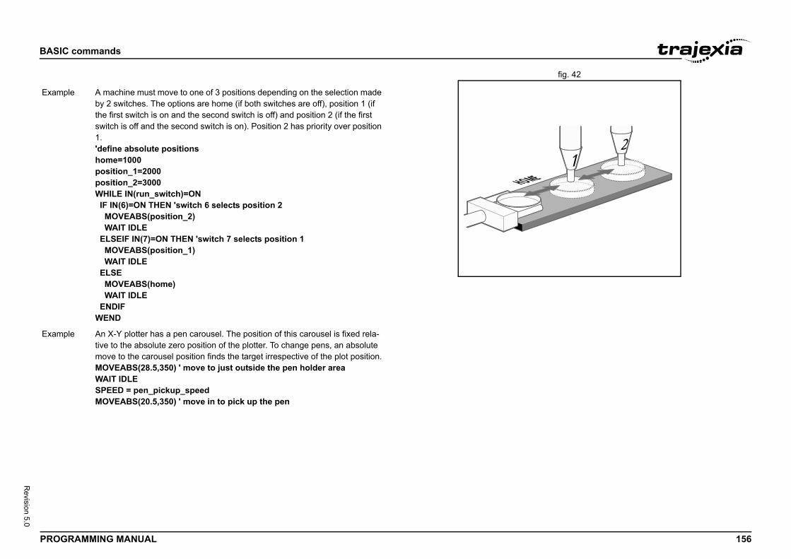
BASIC
PROG 156
Revision 5.0
fig. 42/i
E
Exam
Exam
commands
RAMMING MANUAL
HOM
ple A machine must move to one of 3 positions depending on the selection made by 2 switches. The options are home (if both switches are off), position 1 (if the first switch is on and the second switch is off) and position 2 (if the first switch is off and the second switch is on). Position 2 has priority over position 1.'define absolute positionshome=1000position_1=2000position_2=3000WHILE IN(run_switch)=ON IF IN(6)=ON THEN 'switch 6 selects position 2 MOVEABS(position_2) WAIT IDLE ELSEIF IN(7)=ON THEN 'switch 7 selects position 1 MOVEABS(position_1) WAIT IDLE ELSE MOVEABS(home) WAIT IDLE ENDIFWEND
ple An X-Y plotter has a pen carousel. The position of this carousel is fixed rela-tive to the absolute zero position of the plotter. To change pens, an absolute move to the carousel position finds the target irrespective of the plot position.MOVEABS(28.5,350) ' move to just outside the pen holder areaWAIT IDLESPEED = pen_pickup_speedMOVEABS(20.5,350) ' move in to pick up the pen
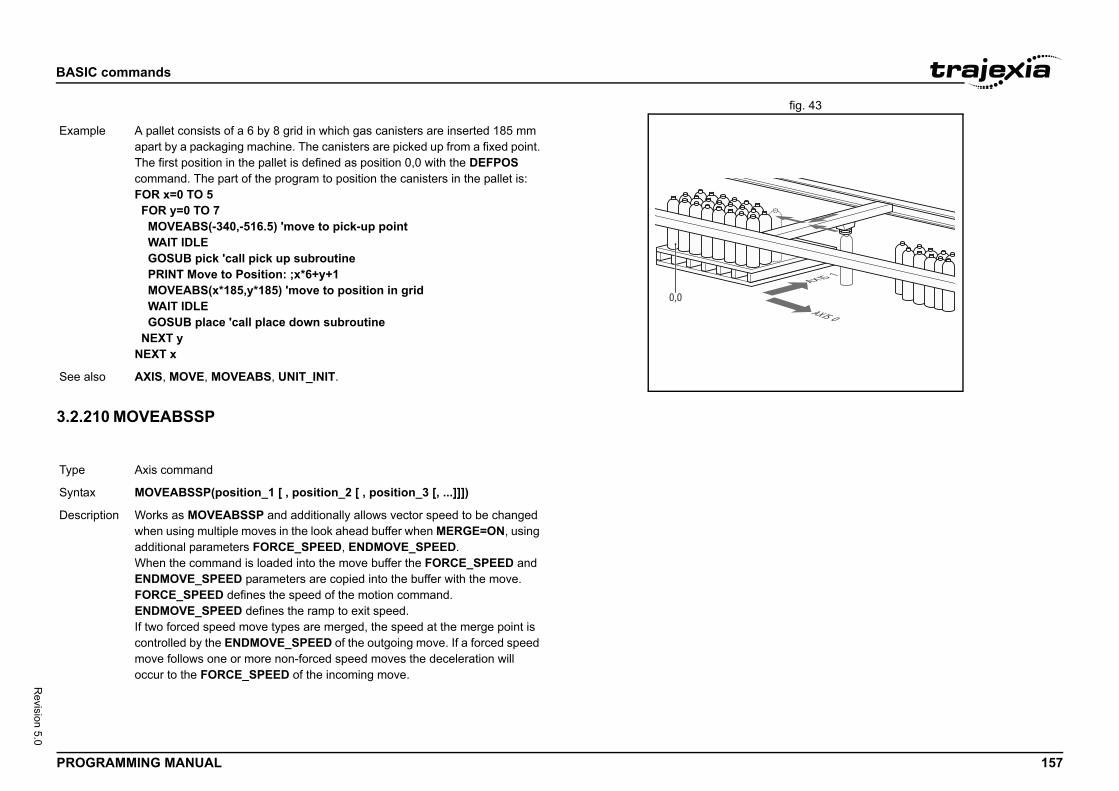
BASIC
PROG 157
Revision 5.0
fig. 43/i
3.2.2/i
AXIS 1
AXIS 0
Exam
See a
Type
Synta
Descr
commands
RAMMING MANUAL
10 MOVEABSSP
0,0
ple A pallet consists of a 6 by 8 grid in which gas canisters are inserted 185 mm apart by a packaging machine. The canisters are picked up from a fixed point. The first position in the pallet is defined as position 0,0 with the DEFPOS command. The part of the program to position the canisters in the pallet is:FOR x=0 TO 5 FOR y=0 TO 7 MOVEABS(-340,-516.5) 'move to pick-up point WAIT IDLE GOSUB pick 'call pick up subroutine PRINT Move to Position: ;x*6+y+1 MOVEABS(x*185,y*185) 'move to position in grid WAIT IDLE GOSUB place 'call place down subroutine NEXT yNEXT x
lso AXIS, MOVE, MOVEABS, UNIT_INIT.
Axis command
x MOVEABSSP(position_1 [ , position_2 [ , position_3 [, ...]]])
iption Works as MOVEABSSP and additionally allows vector speed to be changed when using multiple moves in the look ahead buffer when MERGE=ON, using additional parameters FORCE_SPEED, ENDMOVE_SPEED.When the command is loaded into the move buffer the FORCE_SPEED and ENDMOVE_SPEED parameters are copied into the buffer with the move. FORCE_SPEED defines the speed of the motion command. ENDMOVE_SPEED defines the ramp to exit speed.If two forced speed move types are merged, the speed at the merge point is controlled by the ENDMOVE_SPEED of the outgoing move. If a forced speed move follows one or more non-forced speed moves the deceleration will occur to the FORCE_SPEED of the incoming move.
BASIC
PROG 158
Revision 5.0
3.2.2/i
Argum
Exam
See a
Type
Synta
Descr
commands
RAMMING MANUAL
11 MOVECIRC
ents The command can take up to 64 arguments.• position_i
The position to move to for every axis in user units starting with the base axis.
ple In a series of buffered moves using the look ahead buffer with MERGE=ON, an absolute move is required where the incoming vector speed is 40 units/second and the finishing vector speed is 20 units/second.FORCE_SPEED=40ENDMOVE_SPEED=20MOVEABSSP(100,100)
lso MOVEABS, FORCE_SPEED, ENDMOVE_SPEED
Axis command
x MOVECIRC(end_1,end_2,centre_1,centre_2,direction)MC(end_1,end_2,centre_1,centre_2,direction)
iption The MOVECIRC command interpolates 2 orthogonal axes in a circular arc at the tool point. The path of the movement is determined by the 5 arguments, which are incremental from the current position.The arguments end_1 and centre_1 apply to the BASE axis and end_2 and centre_2 apply to the following axis. All arguments are given in user units of each axis. The speed of movement along the circular arc is set by the SPEED, ACCEL and DECEL parameters of the BASE axis. The first four dis-tance parameters are scaled according to the current unit conversion factor for the BASE axis.MOVECIRC works on the default basis axis group (set with BASE) unless AXIS is used to specify a temporary base axis.For MOVECIRC to be correctly executed, the two axes moving in the circular arc must have the same number of encoder pulses per linear axis distance. If they do not, it is possible to adjust the encoder scales in many cases by adjusting with ENCODER_RATIO axis parameters for a Flexible axis or with the gear ratio in the Servo Drive of a MECHATROLINK-II or EtherCAT axis.
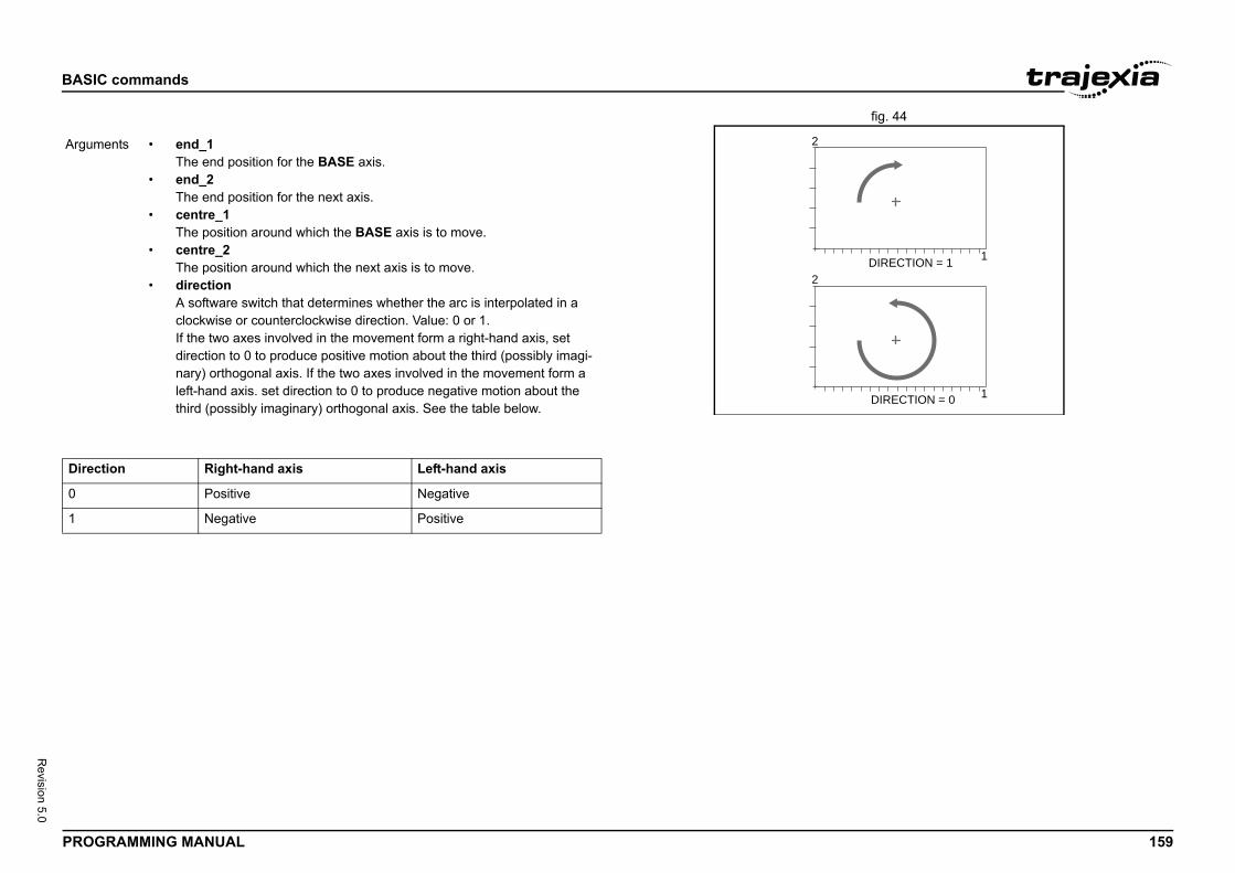
BASIC
PROG 159
Revision 5.0
fig. 44/i
/i
DIRECTION = 1
1
1
DIRECTION = 0
Argum
Direc
0
1
commands
RAMMING MANUAL
2
2
ents • end_1The end position for the BASE axis.
• end_2The end position for the next axis.
• centre_1The position around which the BASE axis is to move.
• centre_2The position around which the next axis is to move.
• directionA software switch that determines whether the arc is interpolated in a clockwise or counterclockwise direction. Value: 0 or 1.If the two axes involved in the movement form a right-hand axis, set direction to 0 to produce positive motion about the third (possibly imagi-nary) orthogonal axis. If the two axes involved in the movement form a left-hand axis. set direction to 0 to produce negative motion about the third (possibly imaginary) orthogonal axis. See the table below.
tion Right-hand axis Left-hand axis
Positive Negative
Negative Positive
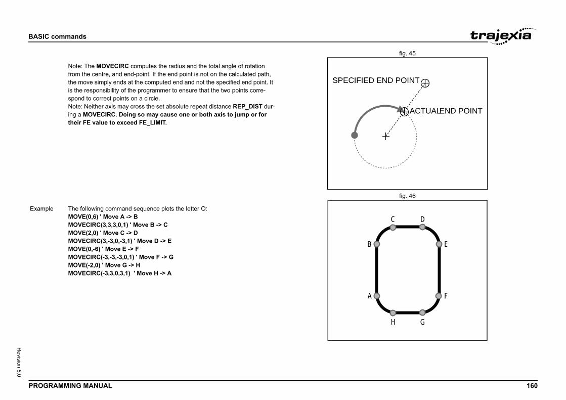
BASIC
PROG 160
Revision 5.0
fig. 45/i
fig. 46/i
D POINT
ACTUAL END POINT
E
C D
H G
F
Exam
commands
RAMMING MANUAL
SPECIFIED EN
Note: The MOVECIRC computes the radius and the total angle of rotation from the centre, and end-point. If the end point is not on the calculated path, the move simply ends at the computed end and not the specified end point. It is the responsibility of the programmer to ensure that the two points corre-spond to correct points on a circle.Note: Neither axis may cross the set absolute repeat distance REP_DIST dur-ing a MOVECIRC. Doing so may cause one or both axis to jump or for their FE value to exceed FE_LIMIT.
B
A
ple The following command sequence plots the letter O:MOVE(0,6) ' Move A -> BMOVECIRC(3,3,3,0,1) ' Move B -> CMOVE(2,0) ' Move C -> DMOVECIRC(3,-3,0,-3,1) ' Move D -> EMOVE(0,-6) ' Move E -> FMOVECIRC(-3,-3,-3,0,1) ' Move F -> GMOVE(-2,0) ' Move G -> HMOVECIRC(-3,3,0,3,1) ' Move H -> A
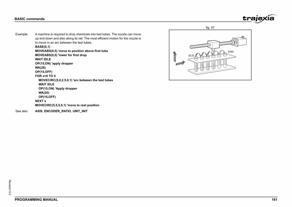
BASIC
PROG 161
Revision 5.0
fig. 47/i
END
Exam
See a
commands
RAMMING MANUAL
(0,5)
AXIS 0
AX
IS 1
ple A machine is required to drop chemicals into test tubes. The nozzle can move up and down and also along its rail. The most efficient motion for the nozzle is to move in an arc between the test tubes.BASE(0,1)MOVEABS(0,5) 'move to position above first tubeMOVEABS(0,0) 'lower for first dropWAIT IDLEOP(15,ON) 'apply dropperWA(20)OP(15,OFF)FOR x=0 TO 5 MOVECIRC(5,0,2.5,0,1) 'arc between the test tubes WAIT IDLE OP(15,ON) 'Apply dropper WA(20) OP(15,OFF)NEXT xMOVECIRC(5,5,5,0,1) 'move to rest position
lso AXIS, ENCODER_RATIO, UNIT_INIT
BASIC
PROG 162
Revision 5.0
3.2.2/i
Type
Synta
Descr
Argum
Exam
See a
e, link_distance, link_acceleration, ink_axis [ , link_option [ , link_position ]])e, link_distance, link_acceleration, ink_axis [ , link_option [ , channel ]])
mand creates a linear move on the base axis linked via o the measured position of a link axis. The link axis can ion to drive the output motion.w the distance the BASE axis moves for a certain dis- (link_distance). The link axis distance is divided into ply to the movement of the base axis. These parts are constant speed and the deceleration. The link accelera- distances are specified by the link_acceleration and
arameters. The constant speed link distance is derived tance and these two parameters.n be divided into separate MOVELINK commands or ether into one. g two rules when setting up the MOVELINK command.ation and deceleration phase with matching speed, the be twice the distance. See the figure. speed phase with matching speeds, the two axes travel o the distance to move must equal the link_distance.n the default basis axis group (set with BASE) unless ify a temporary base axis. The axis set for link_axis
. ned for controlling movements such as: to conveyors
, tapping etc.
nk_acceleration and link_deceleration is greater than are both reduced in proportion in order to equal the sum
commands
RAMMING MANUAL
12 MOVECIRCSP 3.2.213 MOVELINK/i
Axis command
x MOVECIRCSP(end_1, end_2, centre_1, centre_2, direction)
iption Works as MOVECIRCSP and additionally allows vector speed to be changed when using multiple moves in the look ahead buffer when MERGE=ON, using additional parameters FORCE_SPEED, ENDMOVE_SPEED.When the command is loaded into the move buffer the FORCE_SPEED and ENDMOVE_SPEED parameters are copied into the buffer with the move. FORCE_SPEED defines the speed of the motion command. ENDMOVE_SPEED defines the ramp to exit speed.If two forced speed move types are merged, the speed at the merge point is controlled by the ENDMOVE_SPEED of the outgoing move. If a forced speed move follows one or more non-forced speed moves the deceleration will occur to the FORCE_SPEED of the incoming move.
ents • end_1The end position for the BASE axis.
• end_2The end position for the next axis.
• centre_1The position around which the BASE axis is to move.
• centre_2The position around which the next axis is to move.
• directionA software switch that determines whether the arc is interpolated in a clockwise or counterclockwise direction. Value: 0 or 1.If the two axes involved in the movement form a right-hand axis, set direction to 0 to produce positive motion about the third (possibly imagi-nary) orthogonal axis. If the two axes involved in the movement form a left-hand axis. set direction to 0 to produce negative motion about the third (possibly imaginary) orthogonal axis.
ple No example.
lso MOVECIRC, FORCE_SPEED, ENDMOVE_SPEED
Type Axis command
Syntax MOVELINK(distanclink_deceleration, lMOVELINK(distanclink_deceleration, l
Description The MOVELINK coma software gearbox tmove in either directThe parameters shotance of the link axisthree phases that apthe acceleration, thetion and decelerationlink_deceleration pfrom the total link disThe three phases cacan be added up togConsider the followinRule 1: In an accelerlink_distance must Rule 2: In a constantthe same distance sMOVELINK works oAXIS is used to specdrives the base axisMOVELINK is desig• Synchronization• Flying shears• Thread chasing• Coil winding
Note: If the sum of lilink_distance, they to link_distance.
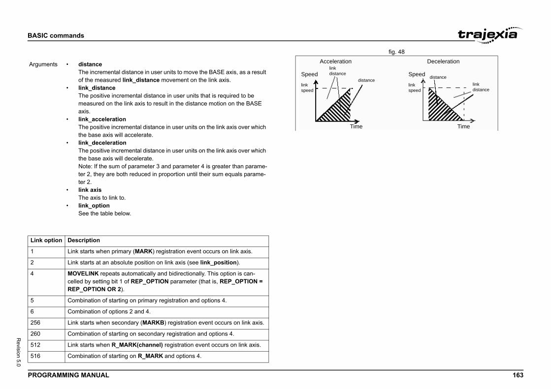
BASIC
PROG 163
Revision 5.0
fig. 48/i
/i
Speed
Time
Deceleration
link distance
link speed
edistance
Argum
Link
1
2
4
5
6
256
260
512
516
commands
RAMMING MANUAL
Acceleration
Speed
Time
link distance
link speed
distanc
ents • distanceThe incremental distance in user units to move the BASE axis, as a result of the measured link_distance movement on the link axis.
• link_distanceThe positive incremental distance in user units that is required to be measured on the link axis to result in the distance motion on the BASE axis.
• link_accelerationThe positive incremental distance in user units on the link axis over which the base axis will accelerate.
• link_decelerationThe positive incremental distance in user units on the link axis over which the base axis will decelerate.Note: If the sum of parameter 3 and parameter 4 is greater than parame-ter 2, they are both reduced in proportion until their sum equals parame-ter 2.
• link axisThe axis to link to.
• link_option See the table below.
option Description
Link starts when primary (MARK) registration event occurs on link axis.
Link starts at an absolute position on link axis (see link_position).
MOVELINK repeats automatically and bidirectionally. This option is can-celled by setting bit 1 of REP_OPTION parameter (that is, REP_OPTION = REP_OPTION OR 2).
Combination of starting on primary registration and options 4.
Combination of options 2 and 4.
Link starts when secondary (MARKB) registration event occurs on link axis.
Combination of starting on secondary registration and options 4.
Link starts when R_MARK(channel) registration event occurs on link axis.
Combination of starting on R_MARK and options 4.
BASIC
PROG 164
Revision 5.0
/i
commands
RAMMING MANUAL
• link_positionThe absolute position where MOVELINK will start when link_option is set to 2
• channelWhen link_option 512 or 516 is selected: registration input number of the TJ2-ECT__
Note: The command uses the BASE and AXIS, and unit conversion factors in a similar way to other MOVE commands.Note: The “link” axis may move in either direction to drive the output motion. The link distances specified are always positive.
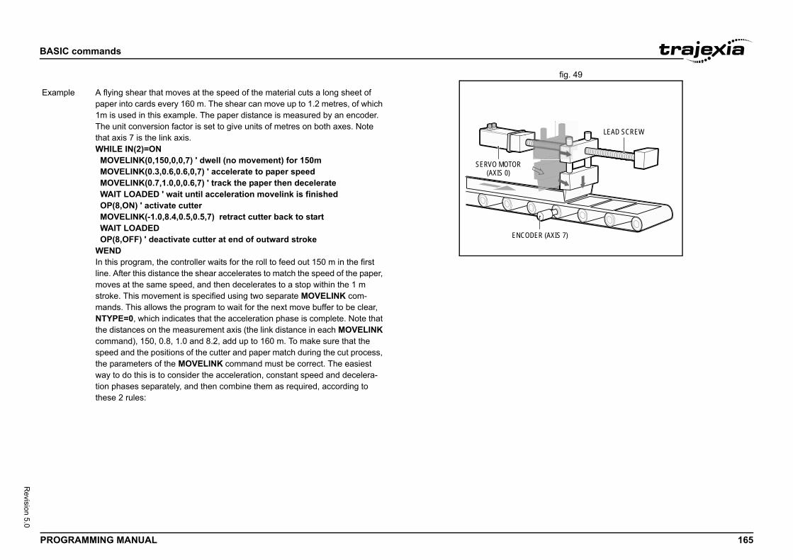
BASIC
PROG 165
Revision 5.0
fig. 49/i
R (AXIS 7)
LEAD SCREW
Exam
commands
RAMMING MANUAL
ENCODE
SERVO MOTOR(AXIS 0)
ple A flying shear that moves at the speed of the material cuts a long sheet of paper into cards every 160 m. The shear can move up to 1.2 metres, of which 1m is used in this example. The paper distance is measured by an encoder. The unit conversion factor is set to give units of metres on both axes. Note that axis 7 is the link axis.WHILE IN(2)=ON MOVELINK(0,150,0,0,7) ' dwell (no movement) for 150m MOVELINK(0.3,0.6,0.6,0,7) ' accelerate to paper speed MOVELINK(0.7,1.0,0,0.6,7) ' track the paper then decelerate WAIT LOADED ' wait until acceleration movelink is finished OP(8,ON) ' activate cutter MOVELINK(-1.0,8.4,0.5,0.5,7) retract cutter back to start WAIT LOADED OP(8,OFF) ' deactivate cutter at end of outward strokeWENDIn this program, the controller waits for the roll to feed out 150 m in the firstline. After this distance the shear accelerates to match the speed of the paper, moves at the same speed, and then decelerates to a stop within the 1 m stroke. This movement is specified using two separate MOVELINK com-mands. This allows the program to wait for the next move buffer to be clear, NTYPE=0, which indicates that the acceleration phase is complete. Note that the distances on the measurement axis (the link distance in each MOVELINK command), 150, 0.8, 1.0 and 8.2, add up to 160 m. To make sure that the speed and the positions of the cutter and paper match during the cut process, the parameters of the MOVELINK command must be correct. The easiest way to do this is to consider the acceleration, constant speed and decelera-tion phases separately, and then combine them as required, according to these 2 rules:
BASIC
PROG 166
Revision 5.0
Exam
commands
RAMMING MANUAL
Rule 1: In an acceleration phase to a matching speed, the link distance must be twice the movement distance. Therefore, the acceleration phase can be specified alone as:MOVELINK(0.3,0.6,0.6,0,1)' move is all accelRule 2: In a constant speed phase with matching speed, the two axes move the same distance. Therefore, the distance to move must be equal the link distance. Therefore, the constant speed phase can be specified as:MOVELINK(0.4,0.4,0,0,1)' all constant speedThe deceleration phase is set in this case to match the acceleration:MOVELINK(0.3,0.6,0,0.6,1)' all decelThe movements of each phase can be added to give the total movement.MOVELINK(1,1.6,0.6,0.6,1)' Same as 3 moves aboveBut in the example above, the acceleration phase is kept separate:MOVELINK(0.3,0.6,0.6,0,1)MOVELINK(0.7,1.0,0,0.6,1)This allows the output to be switched on at the end of the acceleration phase.
ple MOVELINK can be used to create an exact ratio gearbox between two axes. Suppose it is required to create a gearbox link of 4000/3072. This ratio is inexact (1.30208333). If this ratio is entered into a CONNECT command, the axes will slowly creep out of synchronisation. To prevent this problem, set the “link option” to 4 to make MOVELINK repeat continuously.MOVELINK(4000,3072,0,0,linkaxis,4)
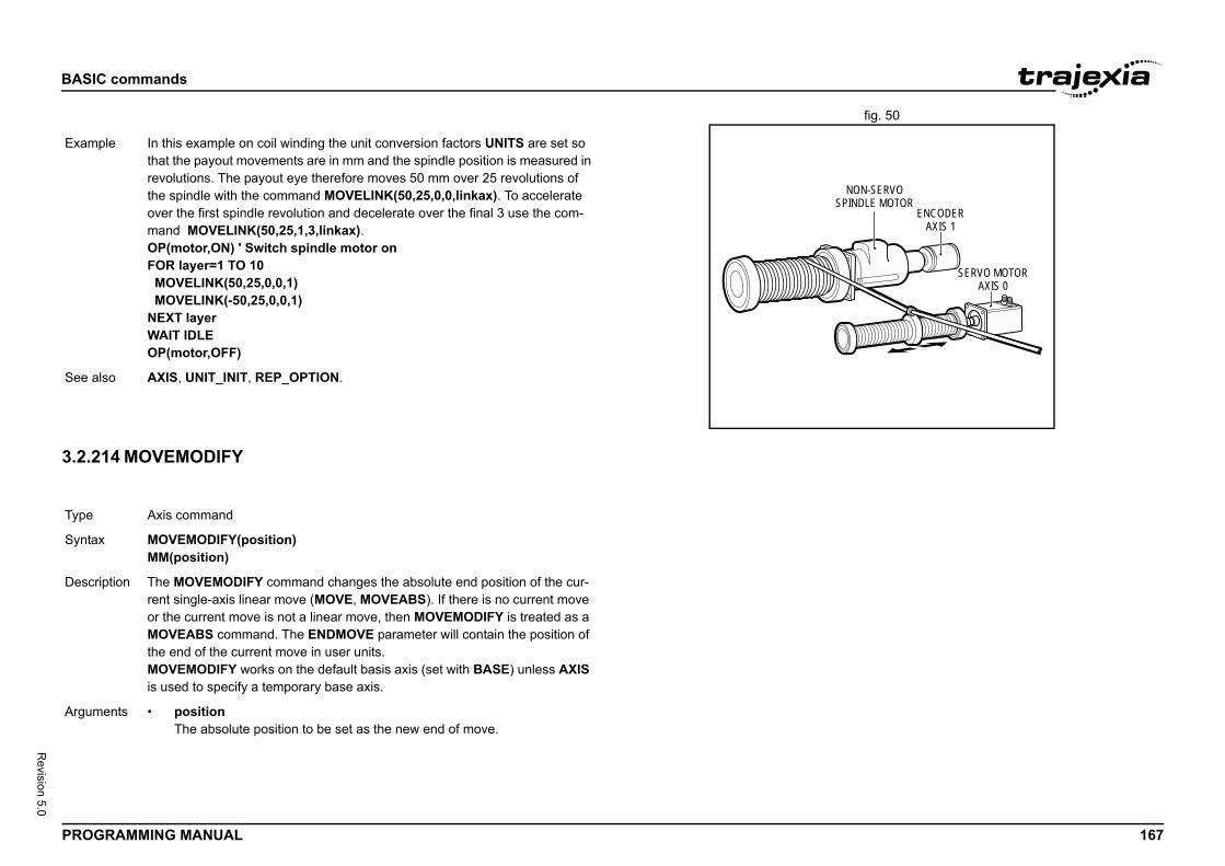
BASIC
PROG 167
Revision 5.0
fig. 50/i
3.2.2/i
ENCODERAXIS 1
NON-SERVOSPINDLE MOTOR
SERVO MOTORAXIS 0
Exam
See a
Type
Synta
Descr
Argum
commands
RAMMING MANUAL
14 MOVEMODIFY
ple In this example on coil winding the unit conversion factors UNITS are set so that the payout movements are in mm and the spindle position is measured in revolutions. The payout eye therefore moves 50 mm over 25 revolutions of the spindle with the command MOVELINK(50,25,0,0,linkax). To accelerate over the first spindle revolution and decelerate over the final 3 use the com-mand MOVELINK(50,25,1,3,linkax).OP(motor,ON) ' Switch spindle motor onFOR layer=1 TO 10 MOVELINK(50,25,0,0,1) MOVELINK(-50,25,0,0,1)NEXT layerWAIT IDLEOP(motor,OFF)
lso AXIS, UNIT_INIT, REP_OPTION.
Axis command
x MOVEMODIFY(position)MM(position)
iption The MOVEMODIFY command changes the absolute end position of the cur-rent single-axis linear move (MOVE, MOVEABS). If there is no current move or the current move is not a linear move, then MOVEMODIFY is treated as a MOVEABS command. The ENDMOVE parameter will contain the position of the end of the current move in user units.MOVEMODIFY works on the default basis axis (set with BASE) unless AXIS is used to specify a temporary base axis.
ents • positionThe absolute position to be set as the new end of move.
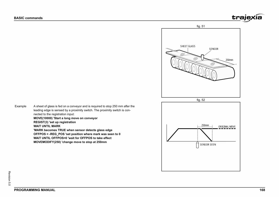
BASIC
PROG 168
Revision 5.0
fig. 51
fig. 52/i
SENSORLASS
250mm
SENSOR SEEN
250mm ORIGINAL MOVE
Exam
commands
RAMMING MANUAL
SHEET G
ple A sheet of glass is fed on a conveyor and is required to stop 250 mm after the leading edge is sensed by a proximity switch. The proximity switch is con-nected to the registration input:MOVE(10000) 'Start a long move on conveyorREGIST(3) 'set up registrationWAIT UNTIL MARK'MARK becomes TRUE when sensor detects glass edgeOFFPOS = -REG_POS 'set position where mark was seen to 0WAIT UNTIL OFFPOS=0 'wait for OFFPOS to take effectMOVEMODIFY(250) 'change move to stop at 250mm
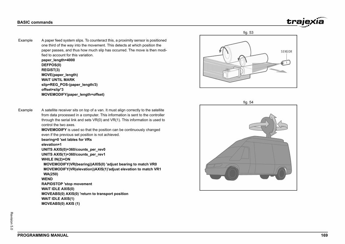
BASIC
PROG 169
Revision 5.0
fig. 53/i
fig. 54/i
SENSOR
Exam
Exam
commands
RAMMING MANUAL
ple A paper feed system slips. To counteract this, a proximity sensor is positioned one third of the way into the movement. This detects at which position the paper passes, and thus how much slip has occurred. The move is then modi-fied to account for this variation.paper_length=4000DEFPOS(0)REGIST(3)MOVE(paper_length)WAIT UNTIL MARKslip=REG_POS-(paper_length/3)offset=slip*3MOVEMODIFY(paper_length+offset)
ple A satellite receiver sits on top of a van. It must align correctly to the satellite from data processed in a computer. This information is sent to the controller through the serial link and sets VR(0) and VR(1). This information is used to control the two axes.MOVEMODIFY is used so that the position can be continuously changed even if the previous set position is not achieved.bearing=0 'set lables for VRselevation=1UNITS AXIS(0)=360/counts_per_rev0UNITS AXIS(1)=360/counts_per_rev1WHILE IN(2)=ON MOVEMODIFY(VR(bearing))AXIS(0) 'adjust bearing to match VR0 MOVEMODIFY(VR(elevation))AXIS(1)'adjust elevation to match VR1 WA(250)WENDRAPIDSTOP 'stop movementWAIT IDLE AXIS(0)MOVEABS(0) AXIS(0) 'return to transport positionWAIT IDLE AXIS(1)MOVEABS(0) AXIS (1)
BASIC
PROG 170
Revision 5.0
3.2.2/i
3.2.2/i
Type
Synta
Descr
Argum
Exam
See a
Type
Synta
Descr
Argum
commands
RAMMING MANUAL
15 MOVES_BUFFERED
16 MOVESP
Axis parameter (read only)
x MOVES_BUFFERED
iption Returns the number of moves being buffered by the axis.
ents N/A
ple No example.
lso ENDMOVE_BUFFER, USER_FRAME
Axis command
x MOVESP(distance_1 [ , distance_2 [ , distance_3 [ , distance_4 [, ...]]]])
iption Works as MOVE and additionally allows vector speed to be changed when using multiple moves in the look ahead buffer when MERGE=ON, using addi-tional parameters FORCE_SPEED, ENDMOVE_SPEED.When the command is loaded into the move buffer the FORCE_SPEED and ENDMOVE_SPEED parameters are copied into the buffer with the move. FORCE_SPEED defines the speed of the motion command. ENDMOVE_SPEED defines the ramp to exit speed.If two forced speed move types are merged, the speed at the merge point is controlled by the ENDMOVE_SPEED of the outgoing move. If a forced speed move follows one or more non-forced speed moves the deceleration will occur to the FORCE_SPEED of the incoming move.
ents The command can take up to 64 arguments.• distance_i
The distance to move for every axis in user units starting with the base axis.
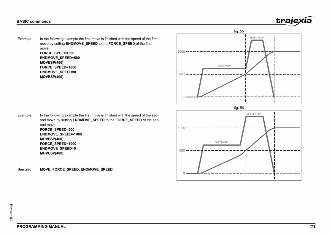
BASIC
PROG 171
Revision 5.0
fig. 55/i
fig. 56/i
/i
SPEED=1000
=500
Exam
500
SPEED=1000Exam
See a
commands
RAMMING MANUAL
0
500
1000
SPEED
ple In the following example the first move is finished with the speed of the first move by setting ENDMOVE_SPEED to the FORCE_SPEED of the first move.FORCE_SPEED=500ENDMOVE_SPEED=500MOVESP(400)FORCE_SPEED=1000ENDMOVE_SPEED=0MOVESP(400)
0
500
1000
SPEED=
ple In the following example the first move is finished with the speed of the sec-ond move by setting ENDMOVE_SPEED to the FORCE_SPEED of the sec-ond move.FORCE_SPEED=500ENDMOVE_SPEED=1000MOVESP(400)FORCE_SPEED=1000ENDMOVE_SPEED=0MOVESP(400)
lso MOVE, FORCE_SPEED, ENDMOVE_SPEED
BASIC
PROG 172
Revision 5.0
3.2.2/i
Type
Synta
Descr
Argum
ystem has a stylus which must be turned so that it is fac-tion as it is travelling at all times. The XY axis pair are ngential stylus axis is 2:
ECTIONle) AXIS(2)
parameter load a MOVETANG which remainsally update the stylus position. The XY axis. The tangential stylus axis is 2:IS(2)
commands
RAMMING MANUAL
17 MOVETANG
Axis command
x MOVETANG(absolute_position [,link_axis])
iption In many X-Y plotting systems, there is a need to keep the stylus oriented in the direction of travel. Each combination of speeds in X and Y results in a Vector value which needs to be fed to a third axis controlling the rotation of the stylus.Examples of machines that require such a control are; glass cutting, knifeblades, powered jig-saws and “pizza wheels”.MOVETANG Moves the axis to the required position using the programmed SPEED, ACCEL and DECEL for the axis. The direction of movement is determined by a calculation of the shortest path to the position assuming that the axis is rotating and that REP_DIST has been set to PI radians (180 degrees) and that REP_OPTION=0.IMPORTANT: The REP_DIST value will depend on the UNITS value and the number of steps representing PI radians. For example if the rotary axis has 4000 pulses/turn and UNITS=1 the REP_DIST value would be 2000.If a MOVETANG command is running and another MOVETANG is executed for the same axis, the original command will not stop, but the endpoint will become the new absolute position.
ents • absolute_positionThe absolute position to be set as the endpoint of the move. Value must be within the range -PI to +PI in the units of the rotary axis. For example if the rotary axis has 4000 pulses/turn, the UNITS value=1 and the angle required is PI/2 (90 deg) the position value would be 1000.
• link_axisAn optional link axis may be specified. When a link_axis is specified the system software calculates the absolute position required each servo cycle based on the link axis TANG_DIRECTION. The TANG_DIRECTION is multiplied by the REP_DIST/PI to calculate the required position. Note that when using a link_axis the absolute_position parameter becomes unused. The position is copied every servo cycle until the MOVETANG is CANCELled
Example An X-Y positioning sing in the same direcaxes 4 and 5. The taBASE(0,1)WHILE TRUE angle=TANG_DIR MOVETANG(ang WA(1)WEND
Or:
Using the link_axis running to automaticpair are axes 4 and 5MOVETANG(0,4) AX
See also TANG_DIRECTION
BASIC
PROG 173
Revision 5.0
3.2.2/i
3.2.2/i
Type
Synta
Descr
Argum
Exam
See a
Type
Synta
Descr
Argum
Exam
See a
x, end_y, end_z, mid_x, mid_y, mid_z, mode)
group defined in BASE along a spherical path with a ined by the SPEED set in the X axis. There are 2 modes option of finishing the move at an endpoint different to to the start point to complete a circle. The path of the ce can be defined either by specifying a point somewhere specifying the centre of the sphere.
end_zCoordinates of the end point.dinates of a second point on the curve.mid_zCoordinates of a point along the path of the curve.Coordinates of the sphere centre.
y the end and mid parameters are used in calculating the ce.point and mid point on curve.point and centre of sphereand mid point 1 are specified and the curve completes a
curve and centre of sphere are specified and the curve circle.inates of the mid point and end point must not be co-lin- cannot be defined by using mode 1 because the sphere co-linear with the endpoint
commands
RAMMING MANUAL
18 MPOS
19 MSPEED
3.2.220 MSPHERICAL/i
Axis parameter (read-only)
x MPOS
iption The MPOS parameter is the measured position of the axis in user units as derived from the encoder. This parameter can be set using the DEFPOS command. The OFFPOS axis parameter can also be used to shift the origin point. MPOS is reset to 0 at start-up or after the controller has been reset, except when using absolute encoders. In that case MPOS is initialised with the absolute position read from the encoder.The range of the measured position is controlled with the REP_DIST and REP_OPTION axis parameters.
ents N/A
ple WAIT UNTIL MPOS >= 1250SPEED = 2.5
lso UNIT_INIT, AXIS, DEFPOS, ENCODER, FE, OFFPOS, REP_DIST, REP_OPTION
Axis parameter (read-only)
x MSPEED
iption The MSPEED parameter contains the measured speed in units/s. It is calcu-lated by taking the change in the measured position in user units in the last servo period and divide it by the servo period (in seconds). The servo period is set with the SERVO_PERIOD parameter.MSPEED represents a snapshot of the speed and significant fluctuations, which can occur, particularly at low speeds. It can be worthwhile to average several readings if a stable value is required at low speeds.
ents N/A
ple No example.
lso AXIS, SERVO_PERIOD, , UNIT_INIT.
Type Axis command
Syntax MSPHERICAL(end_
Description Moves the three axisvector speed determof operation with thethe start, or returningmovement in 3D spaalong the path, or by
Arguments • end_x, end_y, mode = 0 or 1: mode = 2: Coor
• mid_x, mid_y, mode = 0 or 2: mode = 1 or 3:
• modeSpecifies the wacurve in 3D spa0 = specify end 1 = specify end 2 = mid point 2 full circle3 = mid point oncompletes a fullNote.:The coordear. Semicirclescentre would be
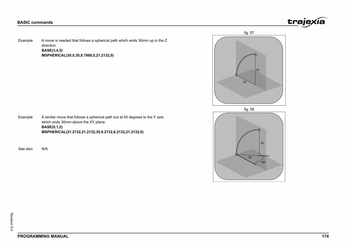
BASIC
PROG 174
Revision 5.0
fig. 57/i
fig. 58/i
/i
30
30
Exam
30
30
45º
Exam
See a
commands
RAMMING MANUAL
ple A move is needed that follows a spherical path which ends 30mm up in the Z direction:BASE(3,4,5)MSPHERICAL(30,0,30,8.7868,0,21.2132,0)
ple A similar move that follows a spherical path but at 45 degrees to the Y axis which ends 30mm above the XY plane:BASE(0,1,2)MSPHERICAL(21.2132,21.2132,30,6.2132,6.2132,21.2132,0)
lso N/A
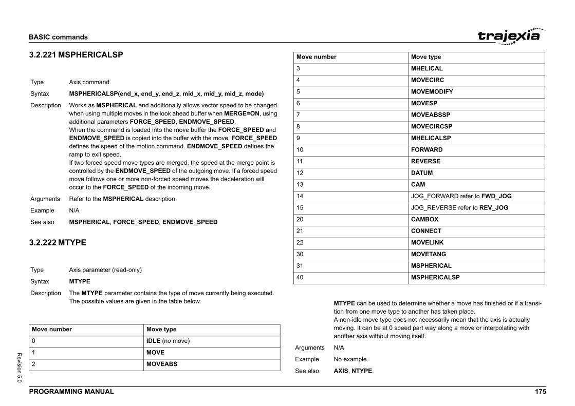
BASIC
PROG 175
Revision 5.0
3.2.2/i
3.2.2/i
/i
Type
Synta
Descr
Argum
Exam
See a
Type
Synta
Descr
Move
0
1
2
MHELICAL
MOVECIRC
MOVEMODIFY
MOVESP
MOVEABSSP
MOVECIRCSP
MHELICALSP
FORWARD
REVERSE
DATUM
CAM
JOG_FORWARD refer to FWD_JOG
JOG_REVERSE refer to REV_JOG
CAMBOX
CONNECT
MOVELINK
MOVETANG
MSPHERICAL
MSPHERICALSP
to determine whether a move has finished or if a transi-ype to another has taken place. does not necessarily mean that the axis is actually
0 speed part way along a move or interpolating with moving itself.
Move type
commands
RAMMING MANUAL
21 MSPHERICALSP
22 MTYPE
/i
Axis command
x MSPHERICALSP(end_x, end_y, end_z, mid_x, mid_y, mid_z, mode)
iption Works as MSPHERICAL and additionally allows vector speed to be changed when using multiple moves in the look ahead buffer when MERGE=ON, using additional parameters FORCE_SPEED, ENDMOVE_SPEED.When the command is loaded into the move buffer the FORCE_SPEED and ENDMOVE_SPEED is copied into the buffer with the move. FORCE_SPEED defines the speed of the motion command. ENDMOVE_SPEED defines the ramp to exit speed.If two forced speed move types are merged, the speed at the merge point is controlled by the ENDMOVE_SPEED of the outgoing move. If a forced speed move follows one or more non-forced speed moves the deceleration will occur to the FORCE_SPEED of the incoming move.
ents Refer to the MSPHERICAL description
ple N/A
lso MSPHERICAL, FORCE_SPEED, ENDMOVE_SPEED
Axis parameter (read-only)
x MTYPE
iption The MTYPE parameter contains the type of move currently being executed. The possible values are given in the table below.
number Move type
IDLE (no move)
MOVE
MOVEABS
3
4
5
6
7
8
9
10
11
12
13
14
15
20
21
22
30
31
40
MTYPE can be usedtion from one move tA non-idle move typemoving. It can be at another axis without
Arguments N/A
Example No example.
See also AXIS, NTYPE.
Move number
BASIC
PROG 176
Revision 5.0
3.2.2/i
3.2.2/i
3.2.2/i
Type
Synta
Descr
Argum
Exam
See a
Type
Synta
Descr
Argum
Exam
See a
Type
Synta
. This allows a negative offset to be applied to the output servo loop. The offset is applied after the DAC_SCALE 327 will represent an offset of 0.1 volts. It is suggested to 70% of the value required to make the stage move in n is used.
sion.
ame" ]
deletes all program lines of the program in the controller. ram name can be used to delete the currently selected ECT). The program name can also be specified without ill delete all programs.lso be used to delete the TABLE memory.name "TABLE" must be in quotes. is implemented for a Command Line Terminal. Within can select the command from the Program menu.
ME, SELECT, TABLE
commands
RAMMING MANUAL
23 N_ANA_IN
24 N_ANA_OUT
25 NEG_OFFSET
3.2.226 NEW/i
3.2.227 NEXT
See FOR..TO..STEP..NEXT.
System parameter (read-only)
x N_ANA_IN
iption This parameter returns the number of analogue input channels connected on the MECHATROLINK-II or EtherCAT network. For example a TJ2-MC__ will return 8 if there are 2 x AN2900 Units connected as each has 4 analogue input channels.
ents N/A
ple No example.
lso N/A
System parameter (read-only)
x N_ANA_OUT
iption This parameter returns the number of analogue output channels connected on the MECHATROLINK-II EtherCAT network. For example a TJ2-MC__ will return 4 if there are 2 x AN2910 Units connected as each has 4 analogue input channels.
ents N/A
ple No example.
lso N/A
System parameter
x NEG_OFFSET=value
Description For Piezo OperationDAC signal from thefunction. An offset ofthat as offset of 65%an open loop situatio
Arguments • valueA BASIC expres
Example No example.
See also N/A
Type Program command
Syntax NEW [ "program_n
Description The NEW commandNEW without a progprogram (using SELquotes. NEW ALL wThe command can aNEW "TABLE" The Note: This commandTrajexia Studio users
Arguments N/A
Example No example.
See also COPY, DEL, RENA
BASIC
PROG 177
Revision 5.0
3.2.2/i
3.2.2/i
Type
Synta
Descr
Argum
Exam
See a
Type
Synta
Descr
Argum
of outputs fitted to the system, or connected on the or EtherCAT network. A TJ2-MC__ with no MECHA-CAT I/O will return NOP=32. The built-in outputs are annels 16 to 27 can be used as “virtual” I/Os which are
ion
erforms the logical NOT function on all bits of the integer n.ction is defined as in the table below.
esult
commands
RAMMING MANUAL
28 NIN
29 NIO
3.2.230 NOP/i
3.2.231 NOT/i
/i
System parameter
x NIN
iption Returns the number of inputs fitted to the system, or connected on the MECHATROLINK-II or EtherCAT network. A TJ2-MC__ with no MECHA-TROLINK-II or EtherCAT I/O will return NIO=32. The built-in inputs are chan-nels 0 to 15. Channels 16 to 27 can be used as “virtual” I/Os which are connected together. Input channels 28 to 31 are reserved to allow each axis to use the MECHATROLINK-II and EtherCAT Drive input channels for axis control functions.Note• A TJ2-ECT__ unit adds 8 inputs, which reflects the status of the 8 regis-
tration inputs on the unit.• A TJ2-KS02 adds 8 inputs, of which the first 2 inputs reflect the status of
the 2 registration inputs.
ents N/A
ple No example.
lso NIO, NOP
System parameter
x NIO
iption Returns the number of inputs/outputs fitted to the system, or connected on the MECHATROLINK-II or EtherCAT network. A TJ2-MC__ with no MECHA-TROLINK-II or EtherCAT I/O will return NIO=32. The built-in inputs are chan-nels 0 to 15. The built-in outputs are channels 8 to 15. Channels 16 to 27 can be used as “virtual” I/Os which are connected together. Input channels 28 to 31 are reserved to allow each axis to use the MECHATROLINK-II and Ether-CAT Drive input channels for axis control functions.NIO is defined as the maximum of the NIN and NOP parameters.
ents N/A
Example No example.
See also NOP, NIN
Type System parameter
Syntax NOP
Description Returns the number MECHATROLINK-II TROLINK-II or Etherchannels 8 to 15. Chconnected together.
Arguments N/A
Example No example.
See also NIN, NIO
Type Mathematical operat
Syntax NOT expression
Description The NOT operator ppart of the expressioThe logical NOT fun
Bit R
0 1
1 0
BASIC
PROG 178
Revision 5.0
/i
3.2.2/i
3.2.2/i
Argum
Exam
See a
Type
Synta
Descr
Argum
Exam
See a
Type
Synta
Descr
Argum
Exam
See a
eter contains an offset that will be applied to the demand out affecting the move which is in progress in any other
position will be changed accordingly in order to keep the POS can therefore be used to effectively datum a system lue set in OFFPOS will be reset to 0 by the system as the
plied on the next servo period. Other commands may be next servo period. Be sure that these commands do not shift has occurred. This can be done by using the WAIT e example).
position by 125, with the Command Line Terminal:
mand position as 0
S=0 ' wait until applied DEFPOS(0).
commands
RAMMING MANUAL
32 NTYPE
33 OFF
3.2.234 OFFPOS/ients • expression.
Any valid BASIC expression.
ple >> PRINT 7 AND NOT 16.0000
lso N/A
Axis parameter (read-only)
x NTYPE
iption The NTYPE parameter contains the type of the move in the next move buffer. Once the current move has finished, the move present in the NTYPE buffer will be executed. The values are the same as those for the MTYPE axis parameter.NTYPE is cleared by the CANCEL(1) command.
ents N/A
ple No example.
lso AXIS, MTYPE.
Constant (read-only)
x OFF
iption The OFF constant returns the numerical value 0.
ents N/A
ple OP (lever,OFF)The above line sets the output named lever to OFF.
lso N/A
Type Axis parameter
Syntax OFFPOS
Description The OFFPOS paramposition (DPOS) withway. The measured Following Error. OFFat full speed. The vaoffset is loaded.Note: The offset is apexecuted prior to theassume the positionUNTIL statement (se
Arguments N/A
Example Change the current >>?DPOS300.0000>>OFFPOS=125>>?DPOS425.0000
Example Define the current deOFFPOS=-DPOSWAIT UNTIL OFFPOThis is equivalent to

BASIC
PROG 179
Revision 5.0
fig. 59/i
3.2.2/i
3.2.2/i
Exam
See a
Type
Synta
Descr
Argum
Exam
See a
Type
Synta
commands
RAMMING MANUAL
35 ON
36 ON.. GOSUB
ple A conveyor transports boxes. Labels must be applied onto these boxes. The REGIST function can capture the position at which the leading edge of the box is seen. Then, the OFFPOS command can adjust the measured position of the axis to make it 0 at that point. Thus, after the registration event has occurred, the measured position (seen in MPOS) reflects the absolute dis-tance from the start of the box. The mechanism that applies the label can take advantage of the absolute position start mode of the MOVELINK or CAMBOX commands to apply the label.BASE(conv)REGIST(3)WAIT UNTIL MARKOFFPOS = -REG_POS ' Leading edge of box is now zero
lso AXIS, DEFPOS, DPOS, MPOS, UNIT_INIT.
Constant (read-only)
x ON
iption The ON constant returns the numerical value 1.
ents N/A
ple OP (lever,ON)The above line sets the output named lever to ON.
lso N/A
Program control command
x ON expression GOSUB label [,label[,...]]
BASIC
PROG 180
Revision 5.0
3.2.2/i
Descr
Argum
Exam
See a
Type
Synta
Descr
Argum
Exam
See a
, value)
ets one or more outputs or returns the state of the first hree different forms depending on the number of argu-
utput_number,value) sets a single output channel. The _number depends on the number of additional digital I/O the MECHATROLINK-II or EtherCAT network and value e output, either 0 or 1.inary_pattern) sets the binary pattern to the 32 outputs value set by binary_pattern.ithout arguments) returns the status of the first 32 out-s multiple outputs to be set without corrupting others be changed.
uts (0 to 7) do not physically exist on the TJ2-MC__. ten to and will always return 0.
rhe output to be set. The range for this parameter number of additional digital I/O connected over the K-II or EtherCAT network. If there are no digital I/O con-e for this parameter is 8..31
output, either OFF (0) or ON (1). All non-0 values are N.
ivalent of the binary pattern is to be output.
equivalent.
commands
RAMMING MANUAL
37 ON.. GOTO
3.2.238 OP/i
iption The ON..GOSUB and ON..GOTO structures enable a conditional jump. The integer expression is used to select a label from the list. If the expression has value 1 the first label is used, for value 2 the second label is used, and so on. Once the label is selected, subroutine GOSUB jump to that label is performed.Note: If the expression is not valid e.g. the result of the expression is less than 1 or greater that the number of available labels in the program, no jump is performed.
ents • expressionAny valid BASIC expression.
• labelAny valid label in the program.
ple REPEAT GET#5,charUNTIL 1<=char and char<=3ON char GOSUB mover, stopper, change
lso GOSUB..RETURN, GOTO.
Program control command
x ON expression GOTO label [,label[,...]]
iption The expression is evaluated and then the integer part is used to select a label from the list. If the expression has the value 1 then the first label is used, 2 then the second label is used, and so on. If the value of the expression is less than 1 or greater than the number of labels then an error occurs. Once the label is selected, subroutine GOTO jump to that label is performed.
ents • expressionAny valid BASIC expression.
• labelAny valid label in the program.
ple REPEAT GET #1,charUNTIL 1<=char and char<=3ON char GOTO mover,stopper,change
lso N/A
Type I/O command
Syntax OP(output_numberOP(binary_pattern)OP
Description The OP command s32 outputs. OP has tments.• Command OP(o
range of outputconnected overis the value to b
• Command OP(baccording to the
• Function OP (wputs. This allowwhich are not to
Note: The first 8 outpThey can not be writ
Arguments • output_numbeThe number of tdepends on theMECHATROLINnected, the rang
• valueThe value to beconsidered as O
• binary_patternThe integer equ
Example OP(12,1)OP(12,ON)These two lines are
BASIC
PROG 181
Revision 5.0
3.2.2/i
Exam
Exam
Exam
See a
Type
Synta
Descr
Argum
Exam
See a
ion
pression2
rforms the logical OR function between corresponding rts of two valid BASIC expressions.ion between two bits is defined as in the table below.
Result
0
1
1
1
expression.
expression.
9) evaluated first, but only the integer part of the result, 18, tion. Therefore, this expression is equivalent to the fol-
ator and so the binary action taking place is:1010 contain the value 26.
2 THEN GOTO label
commands
RAMMING MANUAL
39 OPEN_WIN
3.2.240 OR/i
/i
/i
ple OP(18*256)This line sets the bit pattern 10010 on the first 5 physical outputs, outputs 13 to 17 would be cleared. The bit pattern is shifted 8 bits by multiplying by 256 to set the first available outputs as outputs 0 to 7 do not exist.
ple VR(0) = OPVR(0) = VR(0) AND 65280OP(VR(0))This routine sets outputs 8 to 15 ON and all others off.The above programming can also be written as follows:OP(OP AND 65280)
ple val = 8 ' The value to setmask = OP AND NOT(15*256) ' Get current status and maskOP(mask OR val*256) ' Set val to OP(8) to OP(11)This routine sets value val to outputs 8 to 11 without affecting the other out-puts by using masking.
lso IN.
Axis parameter
x OPEN_WINOW
iption The OPEN_WIN parameter defines the beginning of the window inside or out-side which a registration event is expected. The value is in user units.Note: OPEN_WIN must be the numerically smaller than CLOSE_WIN
ents N/A
ple only look for registration marks between 170 and 230OPEN_WIN = 170CLOSE_WIN = 230REGIST(256+3)WAIT UNTIL MARK
lso CLOSE_WIN, REGIST, UNIT_INIT.
Type Mathematical operat
Syntax expression1 OR ex
Description The OR operator pebits of the integer paThe logical OR funct
Bit 1 Bit 2
0 0
0 1
1 0
1 1
Arguments • expression1Any valid BASIC
• expression2Any valid BASIC
Example result = 10 OR (2.1*The parentheses areis used for the operalowing:result = 10 OR 18The OR is a bit oper01010 OR 10010 = 1Therefore, result will
Example IF KEY OR VR(0) =
See also N/A

BASIC
PROG 182
Revision 5.0
3.2.2/i
/i
/i
3.2.2/i
Type
Synta
Descr
Value
0
1
2
5
6
7
Argum
Exam
See a
Type
Synta
icts the demand output from a servo axis to a lower value he value required varies depending on the maximum
ible. If the voltage output is generated by a 16 bit DAC of 32767 will produce the full +/-10v range. A MECHA-CAT speed axis has a 32 bit maximum demand.y makes sense for Axis types using speed reference.
16384he voltage output to a +/-5V output range from the will apply to the DAC command if SERVO=OFF, or to the servo loop if SERVO=ON.
F_OUT, SERVO.
eter contains the output velocity gain. The output veloc-n is calculated by multiplying the change in measured _GAIN parameter value. The default value is 0.utput velocity gain to a system is mechanically equivalent t is likely to produce a smoother response and allow the ortional gain than could otherwise be used, but at the llowing Errors. High values may cause oscillation and
ing Errors.s are normally required for OV_GAIN.id any instability the servo gains should be changed only off.
_GAIN, VFF_GAIN.
commands
RAMMING MANUAL
41 OUTDEVICE
42 OUTLIMIT
3.2.243 OV_GAIN/i
Communication parameter
x OUTDEVICE
iption The OUTDEVICE parameter defines the default output device. This device will be selected for the PRINT command when the #n option is omitted. The OUTDEVICE parameter is task specific. The supported values are listed in the table below.
Description
Programming port 0 (default)
RS-232C serial port 1
RS-422A/485 serial port 2
Trajexia Studio port 0 user channel 5
Trajexia Studio port 0 user channel 6
Trajexia Studio port 0 user channel 7
ents N/A
ple No example.
lso PRINT, INDEVICE.
Axis parameter
x OUTLIMIT
Description The output limit restrthan the maximum. Tdemand output possvalues an OUTLIMITTROLINK-II or EtherNote: OUTLIMIT onl
Arguments N/A
Example OUTLIMIT AXIS(1) =The above will limit tTJ1-FL02 unit. This voltage output by the
See also AXIS, S_REF, S_RE
Type Axis parameter
Syntax OV_GAIN
Description The OV_GAIN paramity output contributioposition with the OVAdding NEGATIVE oto adding damping. Iuse of a higher propexpense of higher Foproduce high FollowNote: Negative valueNote: In order to avowhen the SERVO is
Arguments N/A
Example No example.
See also D_GAIN, I_GAIN, P
BASIC
PROG 183
Revision 5.0
3.2.2/i
3.2.2/i
Type
Synta
Descr
Argum
Exam
See a
Type
Synta
Descr
Argum
Exam
See a
d-only)
ter contains the status of the task buffers. The parameter ask buffers are occupied, and FALSE if they are empty.tes a movement command, the task loads the movement ask move buffers. The buffers can hold one movement oup of axes. PMOVE will be set to TRUE when loading of completed. When the next servo interrupt occurs, the ds the movement into the next move (NTYPE) buffer of hey are available. When this second transfer has been is cleared to 0 until another move is executed in the task. PMOVE parameter. Use the PROC modifier to access the
in task. Without PROC the current task will be assumed.
e
. This keyword allows a positive offset to be applied to the om the servo loop. The offset is applied after the n. An offset of 327 will represent an offset of 0.1 volts for t generated by a 16 bit DAC. It is suggested that as off-
f the value required to make the stage move in an open .
commands
RAMMING MANUAL
44 P_GAIN
45 PI
3.2.246 PMOVE/i
3.2.247 POS_OFFSET/i
Axis parameter
x P_GAIN
iption The P_GAIN parameter contains the proportional gain. The proportional out-put contribution is calculated by multiplying the Following Error with the P_GAIN parameter value. The default value of P_GAIN for MECHA-TROLINK-II Speed axis (ATYPE = 41) is 131072. The default value for Flexi-ble axis Servo (ATYPE = 44) is 1.0.The proportional gain sets the stiffness of the servo response. Values that are too high will cause oscillation. Values that are too low will cause large Follow-ing Errors.Note: In order to avoid any instability the servo gains should be changed only when the SERVO is off.
ents N/A
ple No example.
lso D_GAIN, I_GAIN, OV_GAIN, VFF_GAIN.
Constant (read-only)
x PI
iption The PI constant returns the numerical constant value of approximately 3.14159.
ents N/A
ple circum = 100PRINT "Radius = "; circum/(2*PI)
lso N/A
Type Task parameter (rea
Syntax PMOVE
Description The PMOVE paramereturns TRUE if the tWhen the task execuinformation into the tinstruction for any grthe buffers has beenmotion generator loathe required axes if tcompleted, PMOVE Each task has its ownparameter for a certa
Arguments N/A
Example No example.
See also NTYPE, PROC.
Type System parameter
Syntax POS_OFFSET=valu
Description For Piezo Operationoutput DAC signal frDAC_SCALE functioaxis with servo outpuset of 65% to 70% oloop situation is used
Arguments N/A
Example No example.
See also N/A
BASIC
PROG 184
Revision 5.0
3.2.2/i
/i
Type
Synta
Descr
Argum
Value
0
1
2
5
6
7
to be printed.
and lower case CAN BE PRINTED"
and variab = 1.5, the print output will be as follows:)-variab
= ";mpos000
semi-colon separator is used. This does not tab into the g the programmer more freedom in where the print items
variab[ 6,2 ]
= ";mpos[ 0 ];" SPEED = ";v[ 2 ];PEED = 12.34
l" OF ";limit;CHR(13);
EX(-2)E
NPUT), OUTDEVICE.
commands
RAMMING MANUAL
48 PRINT /i
Communication command
x PRINT [ #n, ] expression { , expression}? [ #n, ] expression { , expression }
iption The PRINT command outputs a series of characters to the communication ports. PRINT can output parameters, fixed ASCII strings, and single ASCII characters. By using PRINT #n, any port can be selected to output the infor-mation to.Multiple items to be printed can be put on the same line separated by a comma or a semi-colon. A comma separator in the print command places a tab between the printed items. The semi-colon separator prints the next item without any spaces between printed items.The width of the field in which a number is printed can be set with the use of [w,x] after the number to be printed. The width of the column is given by w and the number of decimal places is given by x. Using only one parameter [x] takes the default width and specifies the number of decimal places to be printed. The numbers are right aligned in the field with any unused leading characters being filled with spaces. If the number is too long, then the field will be filled with asterisks to signify that there was not sufficient space to display the number. The maximum field width allowable is 127 characters.The backslash \ command can be used to print a single ASCII character.
ents • nThe specified output device. When this argument is omitted, the port as specified by OUTDEVICE will be used. See the table below.
Description
Programming port 0 (default)
RS-232C serial port 1
RS-422A/485 serial port 2
Trajexia Studio port 0 user channel 5
Trajexia Studio port 0 user channel 6
Trajexia Studio port 0 user channel 7
• expressionThe expression
Example PRINT "CAPITALS
Example Consider VR(1) = 6 PRINT 123.45, VR(1123.4500 4.5000
Example length: PRINT "DISTANCE DISTANCE = 123.0In this example, the next column, allowinare placed.
Example PRINT VR(1)[ 4,1 ]; 6.0 1.50
Example params: PRINT "DISTANCE DISTANCE = 123 S
Example PRINT "ITEM ";tota
Example >> PRINT HEX(15),HF 1FFFFFFFFFFFF
See also $ (HEXADECIMAL I
BASIC
PROG 185
Revision 5.0
3.2.2/i
3.2.2/i
/i
/i
Type
Synta
Descr
Argum
Exam
See a
Type
Synta
Descr
Value
0
1
2
3
Argum
Exam
See a
mand displays the running status of all current tasks with
d-only)
parameter contains the number of the task in which the ogram is running. PROCNUMBER is often required of a program are running on different tasks.
(PROCNUMBER)
OC.
mber, 2,1,VR_start_outputs,no_outputs, _inputs)mber,4,0)
commands
RAMMING MANUAL
49 PROC
50 PROC_STATUS
3.2.251 PROCESS/i
3.2.252 PROCNUMBER/i
3.2.253 PROFIBUS/i
Task command
x PROC(task_number)
iption The PROC modifier allows a process parameter from a particular process to be read or written. If omitted, the current task will be assumed.
ents • task_numberThe number of the task to access.
ple WAIT UNTIL PMOVE PROC(3)=0
lso N/A
Task parameter
x PROC_STATUS
iption The PROC_STATUS parameter returns the status of the process or task specified. The parameter is used with the PROC modifier and can return val-ues listed in the table below.
Description
Process stopped
Process running
Process stepping
Process paused
ents N/A
ple WAIT UNTIL PROC_STATUS PROC(3)=0
lso PROCNUMBER, PROC.
Type Program command
Syntax PROCESS
Description The PROCESS comtheir task number.
Arguments N/A
Example No example.
See also HALT, RUN, STOP.
Type Task parameter (rea
Syntax PROCNUMBER
Description The PROCNUMBERcurrently selected prwhen multiple copies
Arguments N/A
Example MOVE(length) AXIS
See also PROC_STATUS, PR
Type System command
Syntax PROFIBUS(unit_nuVR_start_inputs,noPROFIBUS(unit_nu
BASIC
PROG 186
Revision 5.0
/i
/i
Descr
Bit
0
1
2
Argum
Exam
See a
nable [ , axis, output_number, output_state, position ])
and turns on an output when a predefined position is ff the output when a second position is reached. The d as the measured absolute positions.
n switches each of which can be assigned to any axis. igned its own ON and OFF positions and output number.e used with 2 or all 7 arguments. With only 2 arguments a disabled.ulated on each servo cycle and the output result applied response time is therefore 1 servo cycle period approxi-
remain ON if it was ON when the PSWITCH was disa-he OP command can be used to turn off an output as fol-
P(14,OFF) ' Turn OFF pswitch controlling OP 14witches that are used with PSWITCH are not fast hard-itching is done by software, which can introduce some tion. Fast hardware switching can be used only with axes 1-FL02. Use the HW_PSWITCH command.
ber. Range: [0,15].
le. Range: [on, off].
he axis providing the position input.rtput to set (from 8), including remote outputs
put. Range: [on, off].
sition in user units at which output is set.
sition in user units at which output is reset.
commands
RAMMING MANUAL
3.2.254 PSWITCH/i
iption PROFIBUS function 2 configures the TJ1-PRT for data exchange with the PROFIBUS-DP master unit and defines areas in the VR memory where I/O exchange takes place. PROFIBUS function 4 returns the data exchange sta-tus of the TJ1-PRT. Refer to the table below for the description of the bits in the data exchange status word.
Value Description
0 Failed configuration of I/O data exchange
1 I/O data exchange configured successfully
0 I/O data not available
1 I/O data available
0 Data exchange active in OPERATE mode
1 Data exchange active in CLEAR mode
ents • unit_numberSpecifies the unit number of the TJ1-PRT in the Trajexia system.
• VR_start_outputsThe starting address in VR memory of the controller where the output data from the PROFIBUS-DP master is located.
• no_outputsThe number of output words from the PROFIBUS-DP master in VR memory.
• VR_start_inputsThe starting address in VR memory of the controller where the input data for the PROFIBUS-DP master is located.
• no_inputsThe number of input words to the PROFIBUS-DP master in VR memory.
ple PROFIBUS (0,2,1,10,16,150,31)In this example, the TJ1-PRT is configured to exchange data with PROFI-BUS-DP master with 16 output words (received from the master) located at VR(10) to VR(25), and 31 input words (sent to the master) located at VR(150) to VR(180).
lso N/A
Type I/O command
Syntax PSWITCH(switch, eset_position, reset_
Description The PSWITCH commreached, and turns opositions are specifieThere are 16 positioEach switch has assThe command can bgiven switch can be PSWITCHs are calcto the hardware. Themately.Note: An output maybled. In such cases tlows:PSWITCH(2,OFF):ONote: The physical sware switches, so swsmall delays in operaconnected via the TJ
Arguments • switchThe switch num
• enableThe switch enab
• axisThe number of t
• output_numbeThe physical ou
• output_stateThe state to out
• set_positionThe absolute po
• reset_positionThe absolute po
BASIC
PROG 187
Revision 5.0
Exam
See a
-only)
nel) is set to FALSE when the R_REGIST(channel) executed and is set to TRUE when the registration event rs. Only when this parameter is TRUE, the l) value is valid.
ut number of the TJ2-ECT__
, edge, window)
mand sets up the operation of the registration inputs of a mand captures an axis position when a registration sig-
TJ2-ECT__ supports up to 8 registration inputs (chan-can be assigned to only one axis. The selected axis the TJ2-ECT__ of that channel.event has occurred, the R_MARK(channel) parameter ition is stored in the R_REGPOS(channel) axis parame-stored in the R_REGISTSPEED(channel) axis parame-
commands
RAMMING MANUAL
3.2.255 R_MARK/i
3.2.256 R_REGIST/i
ple A rotating shaft has a cam operated switch which has to be changed for differ-ent size work pieces. There is also a proximity switch on the shaft to indicate the TDC of the machine. With a mechanical cam, the change from job to job is time consuming. This can be eased by using PSWITCH as a software cam switch. The proximity switch is wired to input 7 and the output is output 11. The shaft is controlled by axis 0. The motor has a 900ppr encoder. The output must be on from 80 units.PSWITCH uses the unit conversion factor to allow the positions to be set in convenient units. First the unit conversion factor must be calculated and set. Each pulse on an encoder gives four edges for the TJ2-MC__ to count. There are thus 3,600 edges/rev or 10 edges/degree. If you set the unit conversion factor to 10, you can work in degrees.Next you have to determine a value for all the PSWITCH arguments.
sw:The switch number can be any switch that is not in use. In this exam-ple, you will use number 0.en: The switch must be enabled to work; set the enable to ON.axis: The shaft is controlled by axis 0.opno: The output being controlled is output 11.opst: The output must be on so set to ON.setpos: The output is to produced at 80 units.rspos: The output is to be on for a period of 120 units.
This can all be put together in the following lines of BASIC code:switch: UNITS AXIS(0) = 10 ' Set unit conversion factor REP_DIST = 360 REP_OPTION = ON PSWITCH(0,ON,0,11,ON,80,200)This program uses the repeat distance set to 360 degrees and the repeat option on so that the axis position will be maintained between 0 and 360 degrees.
lso HW_PSWITCH, OP, UNIT_INIT.
Type Axis parameter (read
Syntax R_MARK(channel)
Description The R_MARK(chancommand has been for that channel occuR_REGPOS(channe
Arguments • channelRegistration inp
Example N/A
See also R_REGIST
Type Axis command
Syntax R_REGIST(channel
Description The R_REGIST comTJ2-ECT__. The comnal is detected. The nels). Each channel must be attached to When a registration is set to ON, the poster and the speed is ter.
BASIC
PROG 188
Revision 5.0
3.2.2/i
Argum
Exam
See a
Type
Synta
Descr
Argum
Exam
See a
-only)
l)
annel) parameter stores the position in user units at gistration event occurred.
ut number of the TJ2-ECT__
commands
RAMMING MANUAL
57 R_REGISTSPEED
3.2.258 R_REGPOS/i
ents • channelRegistration input number of the TJ2-ECT__
• edge0 = Rising edge.1 = Falling edge
• window0 = No windowing.1 = Inclusive windowing (position inside OPEN_WIN...CLOSE_WIN)2 = Exclusive windowing (position outside OPEN_WIN...CLOSE_WIN)
ple Assign registration input 1 to EtherCAT axis 2, with rising edge detection and no windowing:R_REGIST(1,0,0) AXIS(2)
Assigning the same input to more than 1 axis will cancel the previous assignments for that input:R_REGIST(1,0,0) AXIS(2)R_REGIST(1,0,0) AXIS(3)This will assign registration of input 1 to axis 3
lso REGIST
Axis parameter (read-only)
x R_REGISTSPEED(channel)
iption The R_REGISTSPEED(channel) parameter stores the speed at the time the registration event for the selected channel occurred.
ents • channelRegistration input number of the TJ2-ECT__
ple N/A
lso R_REGIST
Type Axis parameter (read
Syntax R_REGPOS(channe
Description The R_REGPOS(chwhich the primary re
Arguments • channelRegistration inp
Example N/A
See also R_REGIST
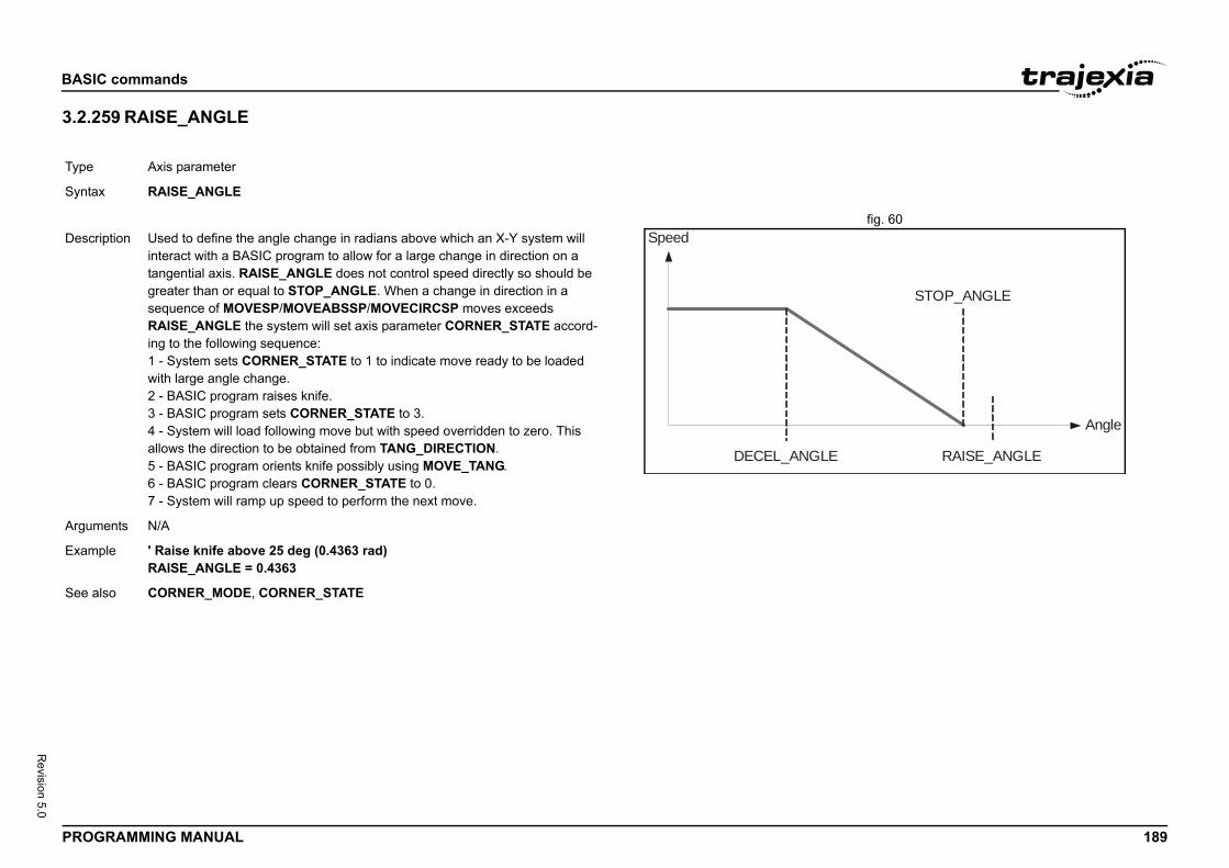
BASIC
PROG 189
Revision 5.0
3.2.2/i
fig. 60/i
Type
Synta
Angle
STOP_ANGLE
RAISE_ANGLE
Descr
Argum
Exam
See a
commands
RAMMING MANUAL
59 RAISE_ANGLE
Axis parameter
x RAISE_ANGLE
Speed
DECEL_ANGLE
iption Used to define the angle change in radians above which an X-Y system will interact with a BASIC program to allow for a large change in direction on a tangential axis. RAISE_ANGLE does not control speed directly so should be greater than or equal to STOP_ANGLE. When a change in direction in a sequence of MOVESP/MOVEABSSP/MOVECIRCSP moves exceeds RAISE_ANGLE the system will set axis parameter CORNER_STATE accord-ing to the following sequence:1 - System sets CORNER_STATE to 1 to indicate move ready to be loaded with large angle change.2 - BASIC program raises knife.3 - BASIC program sets CORNER_STATE to 3.4 - System will load following move but with speed overridden to zero. This allows the direction to be obtained from TANG_DIRECTION.5 - BASIC program orients knife possibly using MOVE_TANG.6 - BASIC program clears CORNER_STATE to 0.7 - System will ramp up speed to perform the next move.
ents N/A
ple ' Raise knife above 25 deg (0.4363 rad)RAISE_ANGLE = 0.4363
lso CORNER_MODE, CORNER_STATE
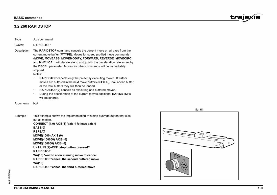
BASIC
PROG 190
Revision 5.0
3.2.2/i
fig. 61/i
Type
Synta
Descr
Argum
Exam
commands
RAMMING MANUAL
60 RAPIDSTOP
Axis command
x RAPIDSTOP
iption The RAPIDSTOP command cancels the current move on all axes from the current move buffer (MTYPE). Moves for speed profiled move commands (MOVE, MOVEABS, MOVEMODIFY, FORWARD, REVERSE, MOVECIRC and MHELICAL) will decelerate to a stop with the deceleration rate as set by the DECEL parameter. Moves for other commands will be immediately stopped.Notes:• RAPIDSTOP cancels only the presently executing moves. If further
moves are buffered in the next move buffers (NTYPE), look ahead buffer or the task buffers they will then be loaded.
• RAPIDSTOP(2) cancels all executing and buffered moves.• During the deceleration of the current moves additional RAPIDSTOPs
will be ignored.
ents N/A
ple This example shows the implementation of a stop override button that cuts out all motion.CONNECT (1,0) AXIS(1) 'axis 1 follows axis 0BASE(0)REPEATMOVE(1000) AXIS (0)MOVE(-100000) AXIS (0)MOVE(100000) AXIS (0)UNTIL IN (2)=OFF 'stop button pressed?RAPIDSTOPWA(10) 'wait to allow running move to cancelRAPIDSTOP 'cancel the second buffered moveWA(10)RAPIDSTOP 'cancel the third buffered move
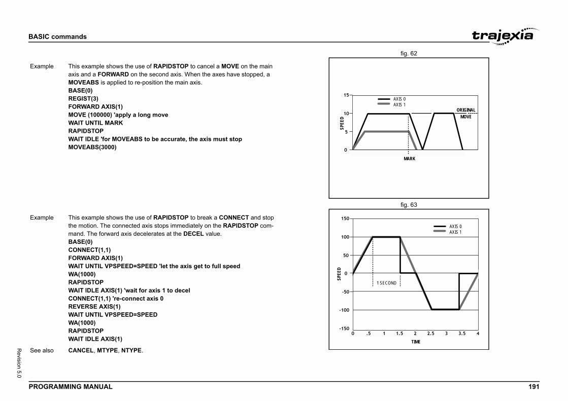
BASIC
PROG 191
Revision 5.0
fig. 62/i
fig. 63/i
AXIS 0AXIS 1
ORIGINALMOVE
MARK
Exam
TIME
COND
AXIS 0AXIS 1
Exam
See a
commands
RAMMING MANUAL
SPEE
D
ple This example shows the use of RAPIDSTOP to cancel a MOVE on the main axis and a FORWARD on the second axis. When the axes have stopped, a MOVEABS is applied to re-position the main axis.BASE(0)REGIST(3)FORWARD AXIS(1)MOVE (100000) 'apply a long moveWAIT UNTIL MARKRAPIDSTOPWAIT IDLE 'for MOVEABS to be accurate, the axis must stopMOVEABS(3000)
SPEE
D
1 SE
ple This example shows the use of RAPIDSTOP to break a CONNECT and stop the motion. The connected axis stops immediately on the RAPIDSTOP com-mand. The forward axis decelerates at the DECEL value.BASE(0)CONNECT(1,1)FORWARD AXIS(1)WAIT UNTIL VPSPEED=SPEED 'let the axis get to full speedWA(1000)RAPIDSTOPWAIT IDLE AXIS(1) 'wait for axis 1 to decelCONNECT(1,1) 're-connect axis 0REVERSE AXIS(1)WAIT UNTIL VPSPEED=SPEEDWA(1000)RAPIDSTOPWAIT IDLE AXIS(1)
lso CANCEL, MTYPE, NTYPE.
BASIC
PROG 192
Revision 5.0
3.2.2/i
3.2.2/i
Type
Synta
Descr
Argum
Exam
See a
Type
Synta
Descr
he output.
he first output of the output range.
he last output of the output range.
e 1, output 12 has value 1, output 13 has value 0, and 1, READ_OP(11,14) returns 13 (1101 bin).
gle output is tested:OP(12) = ON
utputs and call a routine if one of them has value 1:(16, 23)Ntputs
-only)
meter stores the position in user units at which the pri-nt occurred.
commands
RAMMING MANUAL
61 READ_BIT
62 READ_OP
3.2.263 REG_POS/i
System command
x READ_BIT(bit_number, vr_number)
iption The READ_BIT command returns the value of the specified bit in the speci-fied VR variable, either 0 or 1.
ents • bit_numberThe number of the bit to be read. Range: [0,52].
• vr_numberThe number of the VR variable for which the bit is read. Range: [0,64999].
ple No example.
lso CLEAR_BIT, SET_BIT.
I/O command
x READ_OP(output_no)READ_OP(first_output_no, last_output_no)
iption READ_OP(output_no), returns the binary value (0 or 1) of the digital output output_no.READ_OP(first_output_no, last_output_no), returns the number that is the decimal representation of the concatenation of the binary values of the range first_output_no to final_output_no.Note: The difference between first_output_no and last_output_no must be less than 32.Note: Outputs 0 to 7 do not physically exist on the TJ2-MC__. They cannot be written. Their return value is always 0.Note: READ_OP checks the state of the output logic. READ_OP can return the value 1 even if no actual output is present.
Arguments • output_noThe number of t
• first_output_noThe number of t
• last_output_noThe number of t
Example If output 11 has valuoutput 14 has value
Example In this example a sinWAIT UNTIL READ_GOSUB place
Example Check a range of 8 oop_bits = READ_OPIF op_bits <> 0 THE GOSUB check_ouENDIF
See also N/A
Type Axis parameter (read
Syntax REG_POS
Description The REG_POS paramary registration eve
Arguments N/A
BASIC
PROG 193
Revision 5.0
Exam
See a
-only)
rameter stores the position in user units at which the sec-vent occurred.
IST, REG_POS.
commands
RAMMING MANUAL
3.2.264 REG_POSB/i
ple A paper cutting machine uses a CAM profile shape to quickly draw paper through servo driven rollers, and stop the paper so it can be cut. The paper is printed with a registration mark. This mark is detected and the length of the next sheet is adjusted by scaling the CAM profile with the third parameter of the CAM command:' Example Registration Program using CAM stretching:' Set window open and close:length=200OPEN_WIN=10CLOSE_WIN=length-10GOSUB InitialLoop: TICKS=0' Set millisecond counter to 0 IF MARK THEN offset=REG_POS ' This next line makes offset -ve if at end of sheet: IF ABS(offset-length)<offset THEN offset=offset-length PRINT "Mark seen at:"offset[5.1] ELSE offset=0 PRINT "Mark not seen" ENDIF ' Reset registration prior to each move: DEFPOS(0) REGIST(3+768)' Allow mark at first 10mm/last 10mm of sheet CAM(0,50,(length+offset*0.5)*cf,1000) WAIT UNTIL TICKS<-500GOTO LoopNote: variable cf is a constant that is calculated depending on the draw length of the machine per encoder edge.
lso AXIS, MARK, REGIST.
Type Axis parameter (read
Syntax REG_POSB
Description The REG_POSB paondary registration e
Arguments N/A
Example No example.
See also AXIS, MARKB, REG
BASIC
PROG 194
Revision 5.0
3.2.2/i
Type
Synta
Descr
lets the registration to occur only within a specified win-. With this windowing function, registration events are easured position is not greater than the OPEN_WIN axis than the CLOSE_WIN parameter. allows the registration to occur only outside of the speci-ositions. With this windowing function, the registration the axis measured position is not less than the ameter, and greater than the CLOSE_WIN parameter.
eter specifies the registration input and event for use dge the registration event occurs. The mode parameter e use of the windowing function and filtering. e registration.
eter differs per device. The function of each bit in the r is explained in the tables below.
commands
RAMMING MANUAL
65 REGIST /i
Axis command
x REGIST(mode)
iption Depending on the type of unit or Servo Drive, up to 2 registration positions can be captured simultaneously. When a primary registration event has occurred, the MARK axis parameter is set to ON and the position is stored in the REG_POS axis parameter. When a secondary registration event has occurred, the MARKB axis parameter is set to ON and the position is stored in the REG_POSB axis parameter.The TJ1-FL02 and TJ2-KS02 support 2 registration events. Only TJ2-KS02 supports registration with absolute encoder encoders.MECHATROLINK-II and EtherCAT registration can be performed using encoder Z-marker or external registration inputs EXT1, EXT2 or EXT3 on a Servo Drive.For Sigma-II and Sigma-V Servo Drives the registration signals EXT1, EXT2 and EXT3 must be allocated to CN1 inputs with the Drive parameter Pn511.For Junma Servo Drives only one physical input is available, so no settings of Servo Drive parameters are necessary.For G-Series Servo Drives there are three physical inputs. The physical input is associated to logical latch EXT1, EXT2 and EXT3, but the corresponding locations on the CN1 connector are fixed, so no settings of Servo parameters are necessary.For G5-Series Servo Drives the registration signals EXT1, EXT2 and EXT3 must be allocated to CN1 inputs with the Drive parameters Pn400 to Pn407. G5-Series Servo Drives supports 2 registration events.The Accurax G-A/P Servo Drive also supports 2 registration events. For anAccurax G5-A/P Servo Drive the registration signals EXT1 and EXT2 must be allocated to CN1. EXT1 can only bet allocated to SI4 (Pn403) and EXT2 can only be allocated to SI5 (Pn404). When allocating EXT1 and/or EXT2 this must be done for all control-modes.
NOTEFor the mapping of the registration signals of the specific Servo Drives, refer to section 5.1.6.
Inclusive windowing dow of axis positionsignored if the axis mparameter, and less Exclusive windowingfied window of axis pevents are ignored ifOPEN_WIN axis par
Arguments • modeThe mode paramand the signal ealso specifies thUse -1 to disabl
The mode parammode paramete
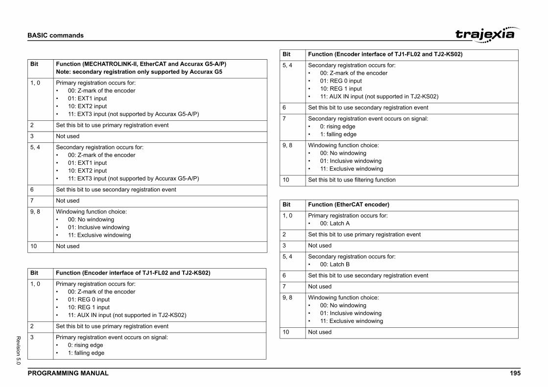
BASIC
PROG 195
Revision 5.0
/i
/i
Bit
1, 0
2
3
5, 4
6
7
9, 8
10
Bit
1, 0
2
3
ccurs for:coder
ot supported in TJ2-KS02)
dary registration event
vent occurs on signal:
ce:
ingwing
g function
coder)
rs for:
y registration event
ccurs for:
dary registration event
ce:
ingwing
rface of TJ1-FL02 and TJ2-KS02)
commands
RAMMING MANUAL
Function (MECHATROLINK-II, EtherCAT and Accurax G5-A/P)Note: secondary registration only supported by Accurax G5
Primary registration occurs for:• 00: Z-mark of the encoder• 01: EXT1 input• 10: EXT2 input• 11: EXT3 input (not supported by Accurax G5-A/P)
Set this bit to use primary registration event
Not used
Secondary registration occurs for:• 00: Z-mark of the encoder• 01: EXT1 input• 10: EXT2 input• 11: EXT3 input (not supported by Accurax G5-A/P)
Set this bit to use secondary registration event
Not used
Windowing function choice:• 00: No windowing• 01: Inclusive windowing• 11: Exclusive windowing
Not used
Function (Encoder interface of TJ1-FL02 and TJ2-KS02)
Primary registration occurs for:• 00: Z-mark of the encoder• 01: REG 0 input• 10: REG 1 input• 11: AUX IN input (not supported in TJ2-KS02)
Set this bit to use primary registration event
Primary registration event occurs on signal:• 0: rising edge• 1: falling edge
5, 4 Secondary registration o• 00: Z-mark of the en• 01: REG 0 input• 10: REG 1 input• 11: AUX IN input (n
6 Set this bit to use secon
7 Secondary registration e• 0: rising edge• 1: falling edge
9, 8 Windowing function choi• 00: No windowing• 01: Inclusive window• 11: Exclusive windo
10 Set this bit to use filterin
Bit Function (EtherCAT en
1, 0 Primary registration occu• 00: Latch A
2 Set this bit to use primar
3 Not used
5, 4 Secondary registration o• 00: Latch B
6 Set this bit to use secon
7 Not used
9, 8 Windowing function choi• 00: No windowing• 01: Inclusive window• 11: Exclusive windo
10 Not used
Bit Function (Encoder inte
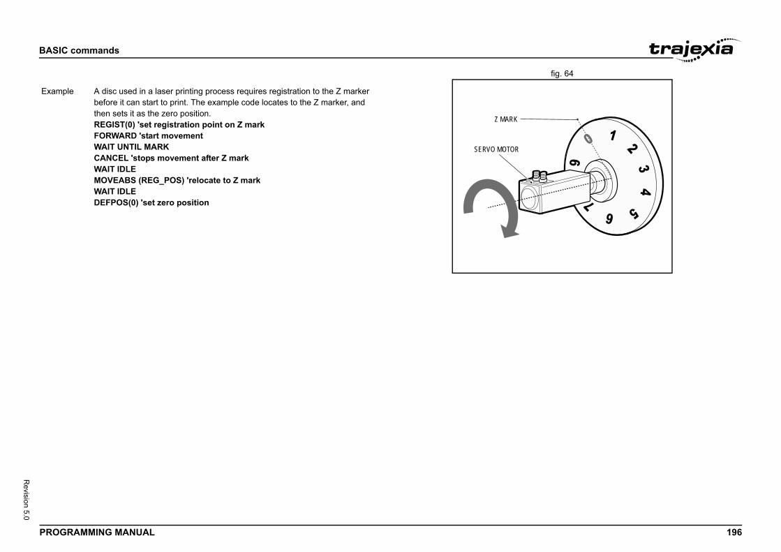
BASIC
PROG 196
Revision 5.0
fig. 64/i
Exam
commands
RAMMING MANUAL
Z MARK
SERVO MOTOR
ple A disc used in a laser printing process requires registration to the Z marker before it can start to print. The example code locates to the Z marker, and then sets it as the zero position.REGIST(0) 'set registration point on Z markFORWARD 'start movementWAIT UNTIL MARKCANCEL 'stops movement after Z markWAIT IDLEMOVEABS (REG_POS) 'relocate to Z markWAIT IDLEDEFPOS(0) 'set zero position
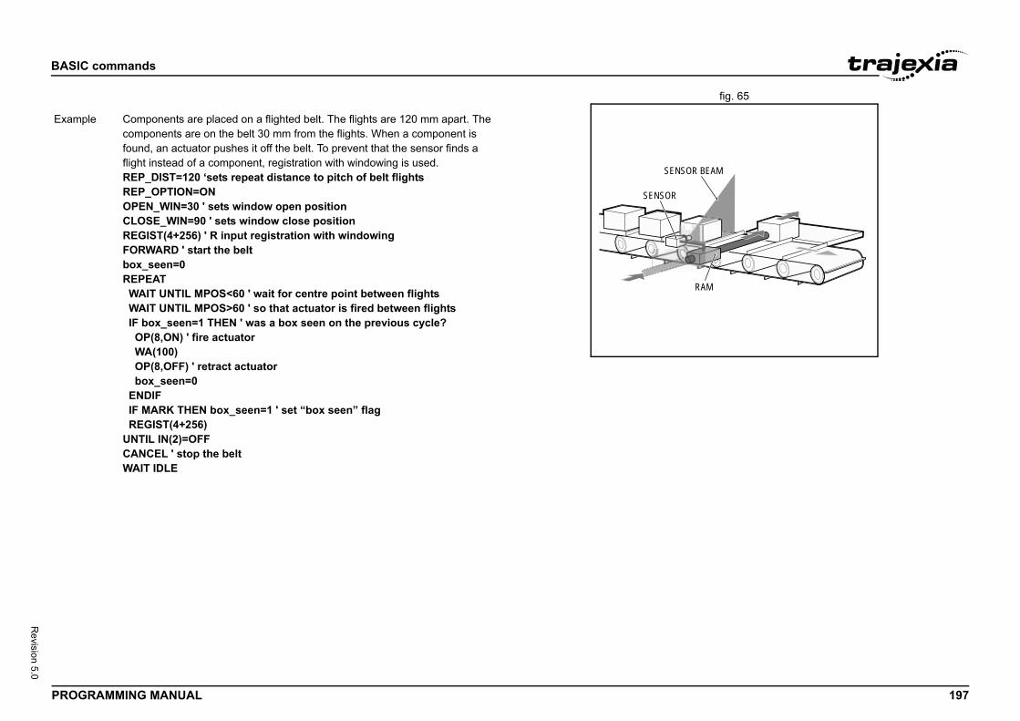
BASIC
PROG 197
Revision 5.0
fig. 65/i
RAM
R BEAM
Exam
commands
RAMMING MANUAL
SENSO
SENSOR
ple Components are placed on a flighted belt. The flights are 120 mm apart. The components are on the belt 30 mm from the flights. When a component is found, an actuator pushes it off the belt. To prevent that the sensor finds a flight instead of a component, registration with windowing is used.REP_DIST=120 ‘sets repeat distance to pitch of belt flightsREP_OPTION=ONOPEN_WIN=30 ' sets window open positionCLOSE_WIN=90 ' sets window close positionREGIST(4+256) ' R input registration with windowingFORWARD ' start the beltbox_seen=0REPEAT WAIT UNTIL MPOS<60 ' wait for centre point between flights WAIT UNTIL MPOS>60 ' so that actuator is fired between flights IF box_seen=1 THEN ' was a box seen on the previous cycle? OP(8,ON) ' fire actuator WA(100) OP(8,OFF) ' retract actuator box_seen=0 ENDIF IF MARK THEN box_seen=1 ' set “box seen” flag REGIST(4+256)UNTIL IN(2)=OFFCANCEL ' stop the beltWAIT IDLE
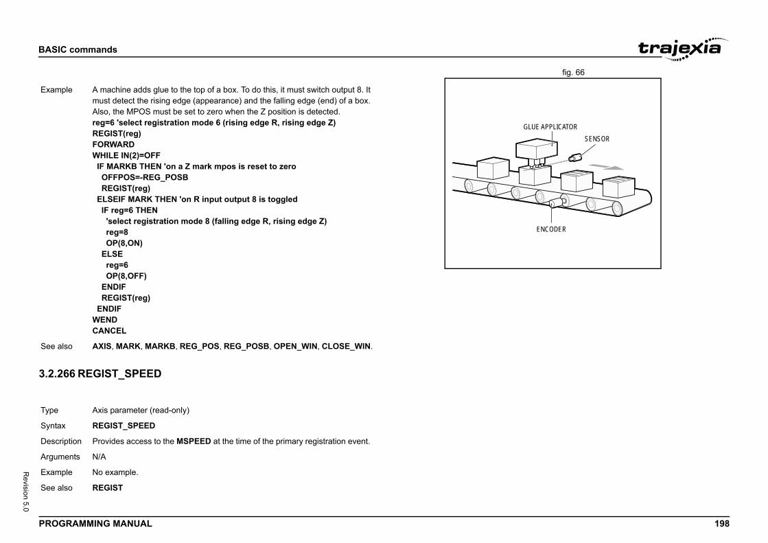
BASIC
PROG 198
Revision 5.0
fig. 66/i
3.2.2/i
ENCODER
SENSORGLUE APPLICATOR
Exam
See a
Type
Synta
Descr
Argum
Exam
See a
commands
RAMMING MANUAL
66 REGIST_SPEED
ple A machine adds glue to the top of a box. To do this, it must switch output 8. It must detect the rising edge (appearance) and the falling edge (end) of a box. Also, the MPOS must be set to zero when the Z position is detected.reg=6 'select registration mode 6 (rising edge R, rising edge Z)REGIST(reg)FORWARDWHILE IN(2)=OFF IF MARKB THEN 'on a Z mark mpos is reset to zero OFFPOS=-REG_POSB REGIST(reg) ELSEIF MARK THEN 'on R input output 8 is toggled IF reg=6 THEN 'select registration mode 8 (falling edge R, rising edge Z) reg=8 OP(8,ON) ELSE reg=6 OP(8,OFF) ENDIF REGIST(reg) ENDIFWENDCANCEL
lso AXIS, MARK, MARKB, REG_POS, REG_POSB, OPEN_WIN, CLOSE_WIN.
Axis parameter (read-only)
x REGIST_SPEED
iption Provides access to the MSPEED at the time of the primary registration event.
ents N/A
ple No example.
lso REGIST
BASIC
PROG 199
Revision 5.0
3.2.2/i
3.2.2/i
Type
Synta
Descr
Argum
Exam
See a
Type
Synta
Descr
Argum
to a slower value 5mm from the end of a move.
IN < 5
ram_name" "new_program_name"
and changes the name of a program in the TJ2-MC__ m names can also be specified without quotes. is implemented for a Command Line Terminal only and rom within programs.
amee of the program.nameof the program.
iture"
commands
RAMMING MANUAL
67 REGIST_SPEEDB
68 REMAIN
3.2.269 RENAME/i
Axis parameter (read-only)
x REGIST_SPEEDB
iption Provides access to the MSPEED at the time of the secondary registration event.
ents N/A
ple No example.
lso REGIST
Axis parameter (read-only)
x REMAIN
iption The REMAIN parameter contains the distance remaining to the end of the current move. It can be checked to see how much of the move has been com-pleted. The units in which REMAIN is expressed depends on the type of the motion command:• If a master axis is moved by MOVELINK or CAMBOX, REMAIN is
expressed in user units set by UNITS.• If a slave axis is moved by MOVELINK or CAMBOX, REMAIN is
expressed in encoder counts.• If a master or a slave axis is moved by a motion command that is not
MOVELINK or CAMBOX, REMAIN is expressed in user units set by UNITS.
The CONNECT command moves an axis without a defined end. For this command, REMAIN has the fixed value of 1000.
ents N/A
Example To change the speedstart: SPEED = 10 MOVE(45) WAIT UNTIL REMA SPEED = 1 WAIT IDLE
See also AXIS, UNIT_INIT
Type Program command
Syntax RENAME "old_prog
Description The RENAME commdirectory. The prograNote: This commandshould not be used f
Arguments • old_program_nThe current nam
• new_program_The new name
Example RENAME "car" "vo
See also COPY, DEL, NEW.
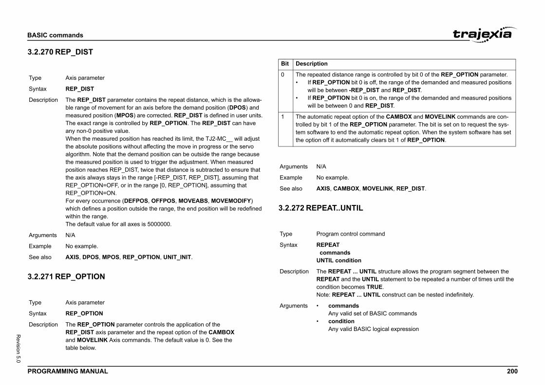
BASIC
PROG 200
Revision 5.0
3.2.2/i
3.2.2/i
Type
Synta
Descr
Argum
Exam
See a
Type
Synta
Descr
is controlled by bit 0 of the REP_OPTION parameter. off, the range of the demanded and measured positions IST and REP_DIST.
on, the range of the demanded and measured positions EP_DIST.
of the CAMBOX and MOVELINK commands are con-PTION parameter. The bit is set on to request the sys-matic repeat option. When the system software has set clears bit 1 of REP_OPTION.
VELINK, REP_DIST.
mand
IL structure allows the program segment between the TIL statement to be repeated a number of times until the RUE.TIL construct can be nested indefinitely.
BASIC commands
logical expression
commands
RAMMING MANUAL
70 REP_DIST
71 REP_OPTION
/i
/i
3.2.272 REPEAT..UNTIL/i
Axis parameter
x REP_DIST
iption The REP_DIST parameter contains the repeat distance, which is the allowa-ble range of movement for an axis before the demand position (DPOS) and measured position (MPOS) are corrected. REP_DIST is defined in user units. The exact range is controlled by REP_OPTION. The REP_DIST can have any non-0 positive value.When the measured position has reached its limit, the TJ2-MC__ will adjust the absolute positions without affecting the move in progress or the servo algorithm. Note that the demand position can be outside the range because the measured position is used to trigger the adjustment. When measured position reaches REP_DIST, twice that distance is subtracted to ensure that the axis always stays in the range [-REP_DIST, REP_DIST], assuming that REP_OPTION=OFF, or in the range [0, REP_OPTION], assuming that REP_OPTION=ON.For every occurrence (DEFPOS, OFFPOS, MOVEABS, MOVEMODIFY) which defines a position outside the range, the end position will be redefined within the range.The default value for all axes is 5000000.
ents N/A
ple No example.
lso AXIS, DPOS, MPOS, REP_OPTION, UNIT_INIT.
Axis parameter
x REP_OPTION
iption The REP_OPTION parameter controls the application of the REP_DIST axis parameter and the repeat option of the CAMBOX and MOVELINK Axis commands. The default value is 0. See the table below.
Bit Description
0 The repeated distance range• If REP_OPTION bit 0 is
will be between -REP_D• If REP_OPTION bit 0 is
will be between 0 and R
1 The automatic repeat optiontrolled by bit 1 of the REP_Otem software to end the autothe option off it automatically
Arguments N/A
Example No example.
See also AXIS, CAMBOX, MO
Type Program control com
Syntax REPEAT commandsUNTIL condition
Description The REPEAT ... UNTREPEAT and the UNcondition becomes TNote: REPEAT ... UN
Arguments • commandsAny valid set of
• conditionAny valid BASIC
BASIC
PROG 201
Revision 5.0
3.2.2/i
3.2.2
See G
3.2.2/i
Exam
See a
Type
Synta
Descr
Argum
Exam
See a
Type
Synta
ter contains the input number to be used as a reverse input range is 0 to 31. Values 0 to 15 represent physically -MC__ I/O connector and are common for all axes.
mapped directly to Drive inputs that are present on the y are unique for each axis. It depends on the type of ervo Drive inputs are mapped into inputs 16 to 31.eter is set to -1, no input is selected. set and the limit is reached, any reverse motion on that Bit 5 of the AXISSTATUS axis parameter will also be set.tive low.
IT, FWD_IN.
meter contains the input number to be used as a jog put can be from 0 to 31. As default the parameter is set to ed.tive low.
WD_JOG, JOGSPEED, UNIT_INIT.
commands
RAMMING MANUAL
73 RESET
74 RETURN
OSUB..RETURN.
75 REV_IN
3.2.276 REV_JOG/i
3.2.277 REVERSE/i
ple A conveyor is to index 100mm at a speed of 1000mm/s, wait for 0.5s and then repeat the cycle until an external counter signals to stop by turning on input 4.cycle:SPEED = 1000REPEAT MOVE(100) WAIT IDLE WA(500)UNTIL IN(4) = ON
lso FOR..TO..STEP..NEXT, WHILE..WEND.
System command
x RESET
iption The RESET command sets the value of all local variables of the current BASIC task to 0.
ents N/A
ple No example.
lso CLEAR.
Axis parameter
x REV_IN
Description The REV_IN paramelimit input. The valid present inputs of TJ2Values 16 to 31 are CN1 connector. TheServo Drive which SAs default the paramIf an input number isaxis will be stopped.Note: This input is ac
Arguments N/A
Example No example.
See also AXIS, AXIS_FS_LIM
Type Axis parameter
Syntax REV_JOG
Description The REV_JOG parareverse input. The in-1, no input is selectNote: This input is ac
Arguments N/A
Example No example.
See also AXIS, FAST_JOG, F
Type Axis command
Syntax REVERSERE
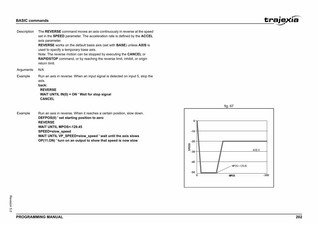
BASIC
PROG 202
Revision 5.0
fig. 67/i
Descr
Argum
Exam
MPOS
AXIS 0
MPOS=-129.45
Exam
commands
RAMMING MANUAL
iption The REVERSE command moves an axis continuously in reverse at the speed set in the SPEED parameter. The acceleration rate is defined by the ACCEL axis parameter.REVERSE works on the default basis axis (set with BASE) unless AXIS is used to specify a temporary base axis.Note: The reverse motion can be stopped by executing the CANCEL or RAPIDSTOP command, or by reaching the reverse limit, inhibit, or origin return limit.
ents N/A
ple Run an axis in reverse. When an input signal is detected on input 5, stop the axis.back: REVERSE WAIT UNTIL IN(0) = ON ' Wait for stop signal CANCEL
SPEE
D
ple Run an axis in reverse. When it reaches a certain position, slow down.DEFPOS(0) ' set starting position to zeroREVERSEWAIT UNTIL MPOS<-129.45SPEED=slow_speedWAIT UNTIL VP_SPEED=slow_speed ' wait until the axis slowsOP(11,ON) ' turn on an output to show that speed is now slow
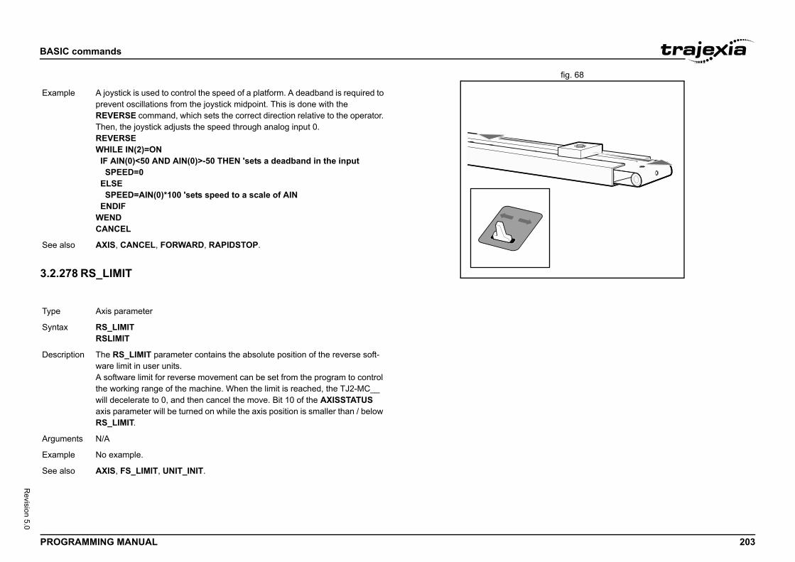
BASIC
PROG 203
Revision 5.0
fig. 68/i
3.2.2/i
Exam
See a
Type
Synta
Descr
Argum
Exam
See a
commands
RAMMING MANUAL
78 RS_LIMIT
ple A joystick is used to control the speed of a platform. A deadband is required to prevent oscillations from the joystick midpoint. This is done with the REVERSE command, which sets the correct direction relative to the operator. Then, the joystick adjusts the speed through analog input 0.REVERSEWHILE IN(2)=ON IF AIN(0)<50 AND AIN(0)>-50 THEN 'sets a deadband in the input SPEED=0 ELSE SPEED=AIN(0)*100 'sets speed to a scale of AIN ENDIFWENDCANCEL
lso AXIS, CANCEL, FORWARD, RAPIDSTOP.
Axis parameter
x RS_LIMITRSLIMIT
iption The RS_LIMIT parameter contains the absolute position of the reverse soft-ware limit in user units.A software limit for reverse movement can be set from the program to control the working range of the machine. When the limit is reached, the TJ2-MC__ will decelerate to 0, and then cancel the move. Bit 10 of the AXISSTATUS axis parameter will be turned on while the axis position is smaller than / below RS_LIMIT.
ents N/A
ple No example.
lso AXIS, FS_LIMIT, UNIT_INIT.
BASIC
PROG 204
Revision 5.0
3.2.2/i
Type
Synta
Descr
Argum
Exam
Exam
Exam
See a
d-only)
arameter contains the number of the last BASIC run-time n the specified task.n RUN_ERROR parameter. Use the PROC modifier to r for a certain task. Without PROC the current task will be
s an overview of error numbers and the associated error
commands
RAMMING MANUAL
79 RUN 3.2.280 RUN_ERROR/i
Program command
x RUN [ "program_name" [ , task_number ]]
iption The RUN command executes the program in the TJ2-MC__ as specified with program_name. RUN with the program name specification will run the cur-rent selected program. The program name can also be specified without quotes.The task number specifies the task number on which the program will be run. If the task number is omitted, the program will run on the highest available task. RUN can be included in a program to run another program.Note: Execution continues until one of the following occurs:• There are no more lines to execute.• HALT is typed at the command line to stop all programs.• STOP is typed at the command line to stop a single program.• The STOP command in the program is encountered.• A run-time error is encountered.
ents • program_nameAny valid program name.
• task_numberAny valid task number. Range: [2,21].
ple >> SELECT "PROGRAM"PROGRAM selected>> RUNThis example executes the currently selected program.
ple RUN "sausage"This example executes the program named sausage.
ple RUN "sausage",3This example executes the program named sausage on task 3.
lso HALT, STOP.
Type Task parameter (rea
Syntax RUN_ERROR
Description The RUN_ERROR perror that occurred oEach task has its owaccess the parameteassumed.The table below givemessages.
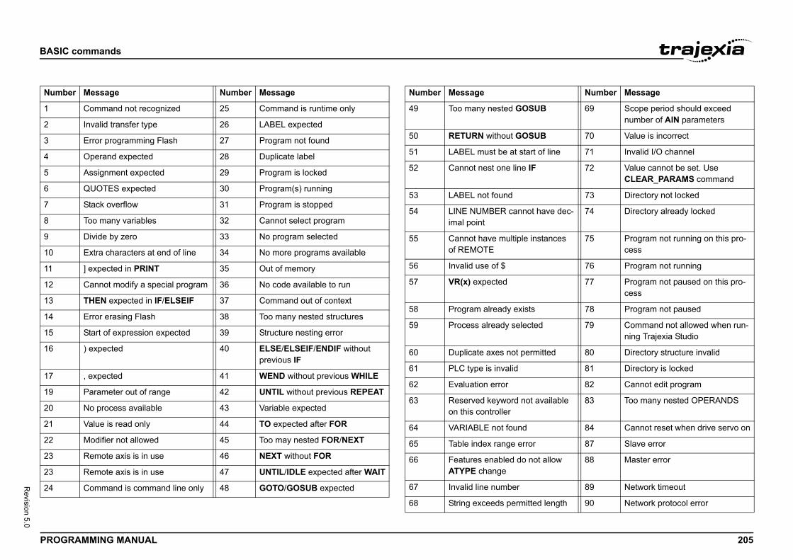
BASIC
PROG 205
Revision 5.0
/i
Numb
1
2
3
4
5
6
7
8
9
10
11
12
13
14
15
16
17
19
20
21
22
23
23
24
Number Message
B 69 Scope period should exceed number of AIN parameters
B 70 Value is incorrect
of line 71 Invalid I/O channel
72 Value cannot be set. Use CLEAR_PARAMS command
73 Directory not locked
have dec- 74 Directory already locked
stances 75 Program not running on this pro-cess
76 Program not running
77 Program not paused on this pro-cess
78 Program not paused
d 79 Command not allowed when run-ning Trajexia Studio
itted 80 Directory structure invalid
81 Directory is locked
82 Cannot edit program
vailable 83 Too many nested OPERANDS
84 Cannot reset when drive servo on
87 Slave error
t allow 88 Master error
89 Network timeout
d length 90 Network protocol error
commands
RAMMING MANUAL
/i
er Message Number Message
Command not recognized 25 Command is runtime only
Invalid transfer type 26 LABEL expected
Error programming Flash 27 Program not found
Operand expected 28 Duplicate label
Assignment expected 29 Program is locked
QUOTES expected 30 Program(s) running
Stack overflow 31 Program is stopped
Too many variables 32 Cannot select program
Divide by zero 33 No program selected
Extra characters at end of line 34 No more programs available
] expected in PRINT 35 Out of memory
Cannot modify a special program 36 No code available to run
THEN expected in IF/ELSEIF 37 Command out of context
Error erasing Flash 38 Too many nested structures
Start of expression expected 39 Structure nesting error
) expected 40 ELSE/ELSEIF/ENDIF without previous IF
, expected 41 WEND without previous WHILE
Parameter out of range 42 UNTIL without previous REPEAT
No process available 43 Variable expected
Value is read only 44 TO expected after FOR
Modifier not allowed 45 Too may nested FOR/NEXT
Remote axis is in use 46 NEXT without FOR
Remote axis is in use 47 UNTIL/IDLE expected after WAIT
Command is command line only 48 GOTO/GOSUB expected
Number Message
49 Too many nested GOSU
50 RETURN without GOSU
51 LABEL must be at start
52 Cannot nest one line IF
53 LABEL not found
54 LINE NUMBER cannot imal point
55 Cannot have multiple inof REMOTE
56 Invalid use of $
57 VR(x) expected
58 Program already exists
59 Process already selecte
60 Duplicate axes not perm
61 PLC type is invalid
62 Evaluation error
63 Reserved keyword not aon this controller
64 VARIABLE not found
65 Table index range error
66 Features enabled do noATYPE change
67 Invalid line number
68 String exceeds permitte
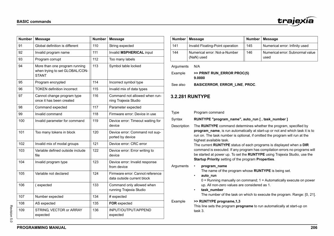
BASIC
PROG 206
Revision 5.0
/i
Numb
91
92
93
94
95
96
97
98
99
100
101
102
103
104
105
106
107
108
109
Number Message
eration 145 Numerical error: Infinity used
umber 146 Numerical error: Subnormal value used
OR PROC(5)
OR_LINE, PROC.
_name", auto_run [ , task_number ]
mand determines whether the program, specified by un automatically at start-up or not and which task it is to ber is optional, if omitted the program will run at the
k.E status of each programs is displayed when a DIR
d. If any program has compilation errors no programs will p. To set the RUNTYPE using Trajexia Studio, use the
ting of the program Properties.
program whose RUNTYPE is being set.
nually on command; 1 = Automatically execute on power values are considered as 1.
he task on which to execute the program. Range: [0, 21].
ame,1,3gram progname to run automatically at start-up on
commands
RAMMING MANUAL
i
3.2.281 RUNTYPE/i
er Message Number Message
Global definition is different 110 String expected
Invalid program name 111 Invalid MSPHERICAL input
Program corrupt 112 Too many labels
More than one program running when trying to set GLOBAL/CON-STANT
113 Symbol table locked
Program encrypted 114 Incorrect symbol type
TOKEN definition incorrect 115 Invalid mix of data types
Cannot change program type once it has been created
116 Command not allowed when run-ning Trajexia Studio
Command expected 117 Parameter expected
Invalid command 118 Firmware error: Device in use
Invalid parameter for command 119 Device error: Timeout waiting for device
Too many tokens in block 120 Device error: Command not sup-ported by device
Invalid mix of modal groups 121 Device error: CRC error
Variable defined outside include file
122 Device error: Error writing to device
Invalid program type 123 Device error: Invalid response from device
Variable not declared 124 Firmware error: Cannot reference data outside current block
( expected 133 Command only allowed when running Trajexia Studio
Number expected 134 # expected
AS expected 135 FOR expected
STRING, VECTOR or ARRAY expected
136 INPUT/OUTPUT/APPEND expected
Number Message
141 Invalid Floating-Point op
144 Numerical error: Not-a-N(NaN) used
Arguments N/A
Example >> PRINT RUN_ERR9.0000
See also BASICERROR, ERR
Type Program command
Syntax RUNTYPE "program
Description The RUNTYPE comprogram_name, is rrun on. The task numhighest available tasThe current RUNTYPcommand is executebe started at power uStartup Priority set
Arguments • program_nameThe name of the
• auto_run0 = Running maup. All non-zero
• task_numberThe number of t
Example >> RUNTYPE prognThis line sets the protask 3.
BASIC
PROG 207
Revision 5.0
3.2.2/i
Exam
See a
Type
Synta
Descr
Argum
Exam
See a
-only)
rameter contains the speed reference value being Drive for both open and closed loop.O=ON), the motion control algorithm will output a speed rmined by the control gain settings and the Following
f the servo motor is determined using the Axis com- (SERVO=OFF), the speed reference signal is deter- axis parameter.
UT AXIS(0)
IMIT, SERVO.
riod, table_start, table_stop, P0 [ , P1 [ , P2 [ , P3 ]]])
nd programs the system to automatically store up to sample period. The storing of data will start as soon as and has been executed.an be any multiple of the servo period. The parameters LE array and can then be read back to a computer and
jexia Studio Data Trace or written to a file for further anal-a of the selected Data Trace.osition for the first parameter which is written by SCOPE SCOPE_POS parameter.
s the SCOPE command when running the Oscilloscope
e CAM command, CAMBOX command and the SCOPE same TABLE as the data area.
commands
RAMMING MANUAL
82 S_REF
3.2.283 S_REF_OUT/i
3.2.284 SCOPE/i
ple >> RUNTYPE progname,0This line sets the program progname to manual running.
lso AUTORUN, EX.
Axis parameter
x S_REFDAC
iption This parameter contains the speed reference value which is applied directly to the Servo Drive when the axis is in open loop (SERVO=OFF).For MECHATROLINK-II the available range is [-1073741824, 1073741824], which corresponds to a range [-servomotor overspeed, servomotor over-speed].For EtherCAT axes S_REF is specified in units/s.For TJ2-KS02 axes S_REF is specified in pulses/s.For Flexible Axis axes, S_REF takes 16 bits, so the available range is [-32768, 32767], which corresponds to a voltage range [-10V, 10V].These ranges can be limited by using the OUTLIMIT parameter.The value currently being applied to the Servo Drive can be read using the S_REF_OUT axis parameter.
ents N/A
ple WDOG = ONSERVO = OFFsquare: S_REF AXIS(0) = 2000 WA(250) S_REF AXIS(0) = -2000 WA(250)GOTO squareThese lines can be used to force a square wave of positive and negative movement with a period of approximately 500ms on axis 0.
lso AXIS, S_REF_OUT, OUTLIMIT, SERVO.
Type Axis parameter (read
Syntax DAC_OUTS_REF_OUT
Description The S_REF_OUT paapplied to the ServoIn closed loop (SERVreference signal deteError. The position omands. In open loopmined by the S_REF
Arguments N/A
Example >> PRINT S_REF_O288.0000
See also AXIS, S_REF, OUTL
Type System command
Syntax SCOPE(control, pe
Description The SCOPE comma4 parameters every the TRIGGER commThe sample period care stored in the TABdisplayed on the Traysis using Save DatThe current TABLE pcan be read from theNotes:1.Trajexia Studio usefunction.2.Applications like thcommand all use the
BASIC
PROG 208
Revision 5.0
3.2.2/i
Argum
Exam
Exam
See a
Type
Synta
Descr
Argum
name"
and specifies the current program for editing, running, list-kes a new program if a program with the name entered rogram name can also be specified without quotes.elected, the commands COMPILE, DEL, LIST, NEW, OP and TROFF will apply to the currently selected pro-m name is specified in the command line. When another
the previously selected program will be compiled. The nnot be changed when a program is running. is implemented for a Command Line Terminal.
RAM"d
T, NEW, RUN, STEPLINE, STOP, TROFF.
ter determines whether the base axis runs under servo SERVO=ON) or open loop (SERVO=OFF). In closed trol algorithm will output a speed reference signal deter- gain settings and the Following Error. The position of the
ined using the Axis commands.ed reference signal is determined by the S_REF axis sition mode).
commands
RAMMING MANUAL
85 SCOPE_POS
3.2.286 SELECT/i
3.2.287 SERVO/i
ents • controlSet on or off to control SCOPE execution. If turned on the SCOPE is ready to run as soon as the TRIGGER command is executed.
• periodThe number of servo periods between data samples.
• table_startThe address of the first element in the TABLE array to start storing data.
• table_stopThe address of the last element in the TABLE array to be used.
• P0First parameter to store.
• P1Optional second parameter to store.
• P2Optional third parameter to store.
• P3Optional fourth parameter to store.
ple SCOPE(ON,10,0,1000,MPOS AXIS(1),DPOS AXIS(1))This example programs the SCOPE function to store the MPOS parameter for axis 1 and the DPOS parameter for axis 1 every 10 servo cycles. The MPOS parameter will be stored in TABLE locations 0 to 499; the DPOS parameters, in TABLE locations 500 to 999. The SCOPE function will wrap and start storing at the beginning again unless stopped. Sampling will not start until the TRIGGER command is executed.
ple SCOPE(OFF)This above line turns the scope function off.
lso SCOPE_POS, TABLE, TRIGGER.
System parameter (read-only)
x SCOPE_POS
iption The SCOPE_POS parameter contains the current TABLE position at which the SCOPE command is currently storing its parameters.
ents N/A
Example No example.
See also SCOPE.
Type Program command
Syntax SELECT "program_
Description The SELECT comming, etc. SELECT madoes not exist. The pWhen a program is sRUN, STEPLINE, STgram unless a prograprogram is selected,selected program caNote: This command
Arguments N/A
Example >> SELECT "PROGPROGRAM selecte>> RUN
See also COMPILE, DEL, LIS
Type Axis parameter
Syntax SERVO
Description The SERVO parameclosed loop control (loop, the motion conmined by the controlservo motor is determIn open loop, the speparameter (not for po
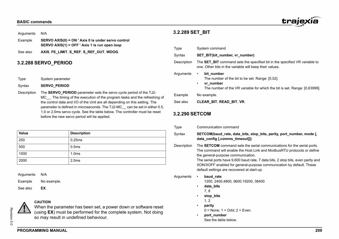
BASIC
PROG 209
Revision 5.0
3.2.2/i
/i
/i
Argum
Exam
See a
Type
Synta
Descr
Value
250
500
1000
2000
Argum
Exam
See a
er, vr_number)
and sets the specified bit in the specified VR variable to variable will keep their values.
he bit to be set. Range: [0,52].
he VR variable for which the bit is set. Range: [0,63999].
_BIT, VR.
mand
, data_bits, stop_bits, parity, port_number, mode [, s_timeout]])
and sets the serial communications for the serial ports. nable the Host Link and ModbusRTU protocols or define communication. 9,600 baud rate, 7 data bits, 2 stop bits, even parity and
for general-purpose communication by default. These ecovered at start-up.
0, 9600,19200, 38400
dd; 2 = Even.
low.
commands
RAMMING MANUAL
88 SERVO_PERIOD
3.2.289 SET_BIT/i
3.2.290 SETCOM/i
ents N/A
ple SERVO AXIS(0) = ON ' Axis 0 is under servo controlSERVO AXIS(1) = OFF ' Axis 1 is run open loop
lso AXIS, FE_LIMIT, S_REF, S_REF_OUT, WDOG.
System parameter
x SERVO_PERIOD
iption The SERVO_PERIOD parameter sets the servo cycle period of the TJ2-MC__. The timing of the execution of the program tasks and the refreshing of the control data and I/O of the Unit are all depending on this setting. The parameter is defined in microseconds. The TJ2-MC__ can be set in either 0.5, 1.0 or 2.0ms servo cycle. See the table below. The controller must be reset before the new servo period will be applied.
Description
0.25ms
0.5ms
1.0ms
2.0ms
ents N/A
ple No example.
lso EX.
CAUTIONWhen the parameter has been set, a power down or software reset (using EX) must be performed for the complete system. Not doing so may result in undefined behaviour.
Type System command
Syntax SET_BIT(bit_numb
Description The SET_BIT commone. Other bits in the
Arguments • bit_numberThe number of t
• vr_numberThe number of t
Example No example.
See also CLEAR_BIT, READ
Type Communication com
Syntax SETCOM(baud_ratedata_config [,comm
Description The SETCOM commThe command will ethe general-purposeThe serial ports haveXON/XOFF enableddefault settings are r
Arguments • baud_rate1200, 2400,480
• data_bits7, 8
• stop_bits1, 2
• parity0 = None; 1 = O
• port_numberSee the table be
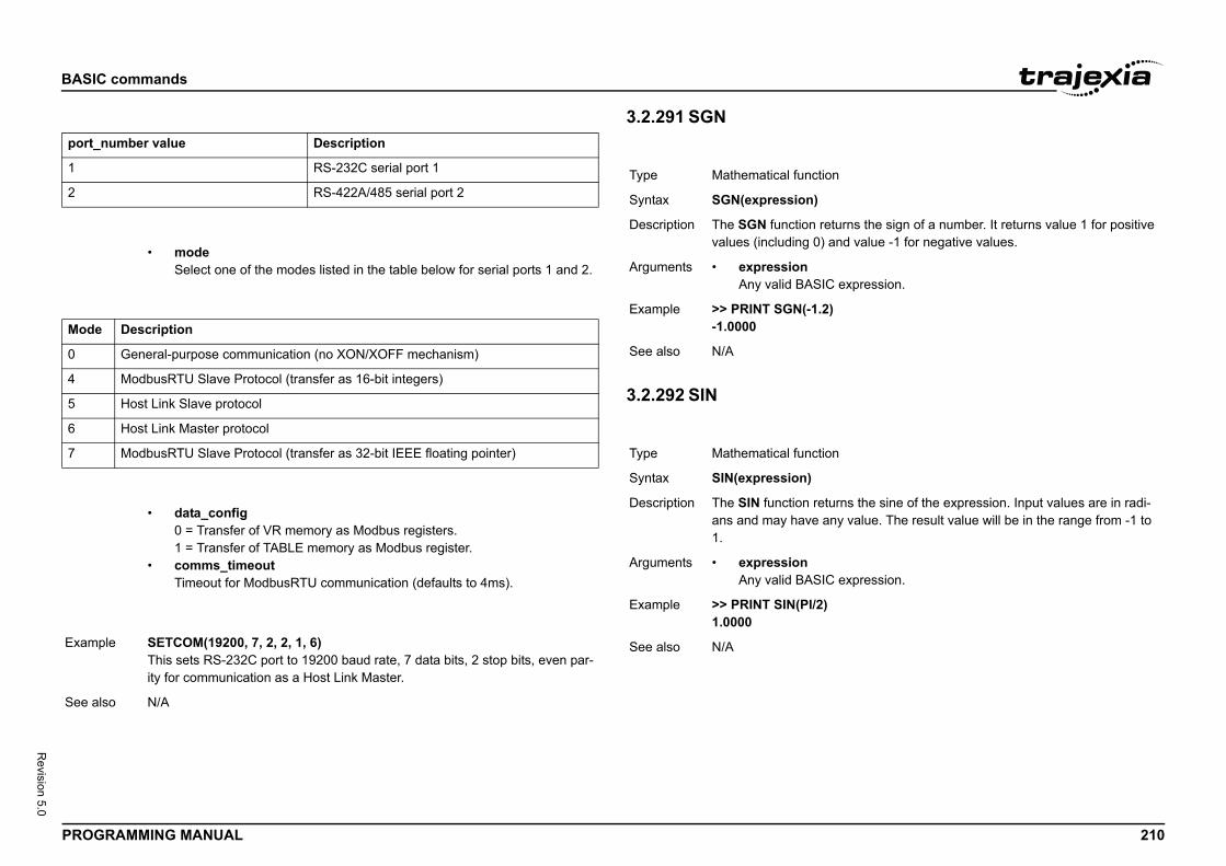
BASIC
PROG 210
Revision 5.0
/i
/i
/i
/i
/i
port_
1
2
Mode
0
4
5
6
7
Exam
See a
n
turns the sign of a number. It returns value 1 for positive and value -1 for negative values.
expression.
)
n
urns the sine of the expression. Input values are in radi-ny value. The result value will be in the range from -1 to
expression.
commands
RAMMING MANUAL
3.2.291 SGN/i
3.2.292 SIN/i
number value Description
RS-232C serial port 1
RS-422A/485 serial port 2
• modeSelect one of the modes listed in the table below for serial ports 1 and 2.
Description
General-purpose communication (no XON/XOFF mechanism)
ModbusRTU Slave Protocol (transfer as 16-bit integers)
Host Link Slave protocol
Host Link Master protocol
ModbusRTU Slave Protocol (transfer as 32-bit IEEE floating pointer)
• data_config0 = Transfer of VR memory as Modbus registers.1 = Transfer of TABLE memory as Modbus register.
• comms_timeoutTimeout for ModbusRTU communication (defaults to 4ms).
ple SETCOM(19200, 7, 2, 2, 1, 6)This sets RS-232C port to 19200 baud rate, 7 data bits, 2 stop bits, even par-ity for communication as a Host Link Master.
lso N/A
Type Mathematical functio
Syntax SGN(expression)
Description The SGN function revalues (including 0)
Arguments • expressionAny valid BASIC
Example >> PRINT SGN(-1.2-1.0000
See also N/A
Type Mathematical functio
Syntax SIN(expression)
Description The SIN function retans and may have a1.
Arguments • expressionAny valid BASIC
Example >> PRINT SIN(PI/2)1.0000
See also N/A
BASIC
PROG 211
Revision 5.0
3.2.2/i
3.2.2/i
3.2.2/i
E
Type
Synta
Descr
Argum
Exam
See a
Type
Synta
Descr
Argum
Exam
See a
Type
Synta
arameter configures the voltage range of the analog put of the TJ1-FL02 when the axis type ATYPE is set
FF, the voltage range of the analog speed reference out-e positive reference voltage corresponds to forward case DPOS and MPOS increment. The negative refer-onds to reverse movements, in which case DPOS and FF is the default setting at power-on.N, the voltage range of the analog speed reference out- OUT1 signal of the TJ1-FL02 for the corresponding axis signal. During forward movements, the controller sets
g reverse movements, the controller sets OUT1 to ON. used for Servo Drives that require both speed and direc-ed reference.
EF_OUT.
table_x, table_y, table_z)
tes of the centre point (x, y, z) of the most recent and z are returned in the TABLE memory area and can inal as required.
y, table_z locations to store the x, y and z coordinates.
10, 11, 12), “;TABLE(11);”, “;TABLE(12)
commands
RAMMING MANUAL
93 SLOT
94 SPEED
95 SPEED_SIGN
3.2.296 SPHERE_CENTR/i
Slot modifier
x SLOT
iption Modifier specifies the unit number for a parameter such as COMMSTYPE. Trajexia unit numbers are 0 to 6, counting from the left most unit.
ents N/A
ple No example.
lso N/A
Axis parameter
x SPEED
iption The SPEED parameter contains the demand speed for an axis in units/s. It can have any positive value (including 0). The demand speed is the maximum speed for the speed profiled motion commands.
ents N/A
ple SPEED = 1000PRINT "Set speed = ";SPEED
lso ACCEL, AXIS, DATUM, DECEL, FORWARD, MOVE, MOVEABS, MOVECIRC, MOVEMODIFY, REVERSE, UNIT_INIT.
Axis parameter
x SPEED_SIGN
Description The SPEED_SIGN pspeed reference outto 44.If SPEED_SIGN = Oput is [-10V, 10V]. Thmovements, in whichence voltage correspMPOS decrement. OIf SPEED_SIGN = Oput is [0V, 10V]. Theis used as a directionOUT1 to OFF. DurinThis setting is to be tion signals as a spe
Arguments N/A
Example No example.
See also ATYPE, S_REF, S_R
Type Axis command
Syntax SPHERE_CENTRE(
Description Returns the coordinaMSPHERICAL. x, y be printed to the term
Arguments • table_x, table_TABLE memory
Example SPHERE_CENTRE(PRINT TABLE(10);”
See also MSPHERICAL
BASIC
PROG 212
Revision 5.0
3.2.2/i
3.2.2/i
T
Type
Synta
Descr
Argum
Exam
See a
Type
Synta
Descr
Argum
ansition into the acceleration, an S-curve is applied with
factor, the acceleration takes 100 ms to reach the set =50, the acceleration takes 150 ms but the rate of ue) is controlled. i.e. Jerk is limited.
only)
o examine the start direction in radians of the last pro-MOVEABSSP/MOVECIRCSP move of 2 or more axes.
0000)ST
)ST
commands
RAMMING MANUAL
97 SQR
98 SRAMP 3.2.299 START_DIR_LAS/i
3.2.300 STEP
See FOR..TO..STEP..NEXT.
Mathematical function
x SQR(expression)
iption The SQR function returns the square root of the expression. The expression must have positive (including 0) value.
ents • expressionAny valid BASIC expression.
ple >> PRINT SQR(4)2.0000
lso N/A
Axis parameter
x SRAMP
iption The SRAMP parameter contains the S-curve factor. The S-curve factor con-trols the amount of rounding applied to the trapezoidal profiles. SRAMP should be set, when a move is not in progress, to a maximum of half the ACCEL/DECEL time. The setting takes a short while to be applied after changes. The default value of the parameter is 0.SRAMP is applied to the FORWARD, MOVE, MOVEABS, MOVECIRC, MHELICAL and REVERSE commands. Notes:• Using S-curves increases the time required for the movement to com-
plete.• The S-curve factor must not be changed while a move is in progress. If
for example SRAMP is changed from 0 to 200, then start a move within 200 ms, the full SRAMP setting will not be applied.
ents Time between 0..250 ms
Example To provide smooth tra time of 50ms.
SPEED = 160000ACCEL = 1600000DECEL = 1600000SRAMP = 50WA(50)MOVEABS(100000)
Without the S-curve speed. With SRAMPchange of force (torq
See also AXIS.
Type Axis parameter (read
Syntax START_DIR_LAST
Description Allows the program tgrammed MOVESP/
Arguments N/A
Example >>MOVESP(10000,1>>? START_DIR_LA0.7854>>MOVESP(0,10000>>? START_DIR_LA0.0000
See also MOVESP.
BASIC
PROG 213
Revision 5.0
3.2.3/i
Type
Synta
Descr
Argum
as X and Y but the axes ' steps per mm are not the oves require identical UNITS values on both axes in
th speed constant and for MOVECIRC to work correctly. er resolution is changed to match the higher step resolu-intain the best accuracy for both axes. per mm (31.25 steps per mm) per mm (50.00 steps per mm)
00)
am_name" [ , task_number ]]
mand executes one line (i.e., "steps") in the program _name. The program name can also be specified with-
INE is executed without program name on the command ted program will be stepped. If STEPLINE is executed e in a program this program will be stepped.
cified then all occurrences of this program will be will be started when there is no copy of the program run-ecified as well then only the copy of the program running will be stepped. If there is no copy of the program run- task then one will be started on it.
program to be stepped.
he task with the program to be stepped. Range: [0,21].
veyor"
hs",2
P, TROFF, TRON.
commands
RAMMING MANUAL
01 STEP_RATIO
3.2.302 STEPLINE/i
Axis command
x STEP_RATIO(numerator, denominator)
iption This command sets up a ratio for the output of the stepper axis. Every servo-period the number of steps is passed through the STEP_RATIO function before it goes to the step pulse output.Pulse Count Out = (numerator / denominator) * DPOS.STEP_RATIO affects both MOVECIRC and CAMBOX.Notes:• The STEP_RATIO function operates before the divide by 16 factor in the
stepper axis.• Large ratios should be avoided as they will lead to either loss of resolu-
tion or much reduced smoothness in the motion. The actual physical step size x 16 is the basic resolution of the axis and use of this command may reduce the ability of the Motion Controller to accurately achieve all posi-tions.
• STEP_RATIO does not replace UNITS. Do not use STEP_RATIO to remove the x16 factor on the stepper axis as this will lead to poor step frequency control.
• Executing STEP_RATIO without parameters will print the current numer-ator and denominator.
ents • numeratorAn integer number between 0 and 16777215 that is used to define the numerator in the above equation.
• denominatorAn integer number between 0 and 16777215 that is used to define the denominator in the above equation.
Example Two axes are set upsame. Interpolated morder to keep the paThe axis with the lowtion axis so as to ma' Axis 0: 500 counts' Axis 1: 800 countsBASE(0)STEP_RATIO(500,8UNITS = 800BASE(1)UNITS = 800
See also ENCODER_RATIO
Type Program command
Syntax STEPLINE [ "progr
Description The STEPLINE comspecified by programout quotes. If STEPLline the current selecwithout program namIf the program is spestepped. A new taskning. If the task is spon the specified taskning on the specified
Arguments • program_nameThe name of the
• task_numberThe number of t
Example >> STEPLINE "con
Example >> STEPLINE "mat
See also RUN, SELECT, STO
BASIC
PROG 214
Revision 5.0
3.2.3/i
3.2.3/i
Type
Synta
Descr
Argum
Exam
Exam
See a
Type
Synta
Descr
Argum
(0.4363 rad)363
_time, [sync_position, sync_axis, pos1[, pos2
d is used to synchronise one axis with a moving position can be used to synchronise a robot to a point on a con-define a time to synchronise and de-synchronise.ovement on the base axis is the sum of two parts:
vement from the ‘sync_pos’, this is the movement of the the conveyor. ‘pos1’, this is the position in the current coordinate sys-pos was captured on the slave axis.chronised it will follow the movements on the ‘sync_axis’. ot fill the MTYPE buffer you can perform movements
et loaded in to the move buffer it is not cancelled by TOP, you have to perform SYNC(4). When a software or
ched the SYNC is immediately stopped with no decelera-
e the captured position REG_POS, or a position from a ‘sync_position’. The pos1, pos2 and pos3 are typically nsor/ vision system in the current USER_FRAME.
commands
RAMMING MANUAL
03 STOP
04 STOP_ANGLE
3.2.305 SYNC/i
Program command
x STOP [ "program_name" [ , task_number ]
iption The STOP command will halt execution of the program specified with program_name. If the program name is omitted, then the currently selected program will be halted. The program name can also be specified without quotes.In case of multiple executions of a single program on different tasks the task_number can be used to specify the specific task to be stopped.
ents • program_nameThe name of the program to be stopped.
• task_numberThe number of the task with the program to be stopped. Range: [2,21].
ple >> STOP progname
ple The lines from label on will not be executed in this example.STOPlabel: PRINT var RETURN
lso HALT, RUN, SELECT.
Axis parameter
x STOP_ANGLE
iption Used to define the angle change in radians above which an X-Y system should decelerate to zero speed. Operation of STOP_ANGLE applies to MOVESP/MOVEABSSP/MOVECIRCSP and depends on setting of DECEL_ANGLE and CORNER_MODE. If the X-Y system turns through an angle between STOP_ANGLE and DECEL_ANGLE the system will slow down to an intermediate speed.
ents N/A
Example ' Stop above 25 degSTOP_ANGLE = 0.4
See also DECEL_ANGLE
Type Axis command
Syntax SYNC(control, sync[,pos3]]])
Description The SYNC commanon another axis. Thisveyor. The user can The synchronising m1. The conveyor modemand point along 2. The movement totem where the sync_When the axis is synAs the SYNC does nwhile synchronised.Warning:As SYNC does not gCANCEL or RAPIDShardware limit is reation.Tip:Typically you can usvision system for thethe position of the se
BASIC
PROG 215
Revision 5.0
Argum p the components from one conveyor and place them at econd. The registration sensor is at 385mm from the robots the second conveyor is 400mm from the robots origin. x, axis(1) - robot axis y zt rotateal robot axis, FRAME=14 can be applied to theser axisr axisconveyors that you wish to link toyor offsets
ition.
) ' reset conveyor position for place))
0) AXIS(10)K AXIS(10)
EG_POS, 10, sen_xpos , conv1_yoff)C_CONTROL AXIS(0)=3ed
lace_pos, 11, conv2_xoff, conv2_yoff)C_CONTROL AXIS(0)=3ed
e_pos + 100
SYNC_TIMER, USER_FRAME, USER_FRAMEB
commands
RAMMING MANUAL
ents • control1 = Start synchronisation, requires minimum first 5 parameters4 = Stop synchronisation, requires minimum first 2 parameters10 = Re-synchronise to another axis belonging to the same USER_FRAME, requires minimum first 5 parameters20 = Re-synchronise to another axis belonging to USER_FRAMEB (for example a conveyor which is not aligned with any of the axes of the robot), requires minimum first 5 parameters
• sync_timeTime to complete the synchronisation movement in milliseconds
• sync_positionThe captured position on the sync_axis.
• sync_axisThe axis to synchronise with.
• pos1Absolute position on the first axis on the base array
• pos2Absolute position on the second axis on the base array
• pos3Absolute position on the third axis on the base array
Example The robot must pick u100mm pitch on the sorigin and the start of'axis(0) - robot axis'axis(2) - robot axis'axis(3) - robot wris'These are the actu'axis(10) - conveyo'axis(11) - conveyo'These are the real 'Sensor and convesen_xpos = 385conv1_yoff = 200conv2_yoff = -250conv2_xoff = 40place_pos = 0BASE(0,1)'Move to home posMOVEABS(200,50)'start conveyorsDEFPOS(0) AXIS(11FORWARD AXIS(10FORWARD AXIS(11WAIT IDLEWHILE(running) REGIST(20,0,0,0, WAIT UNTIL MAR SYNC(1, 1000, R WAIT UNTIL SYN 'Now synchronis GOSUB pick SYNC(10, 1000, p WAIT UNTIL SYN 'Now synchronis GOSUB place SYNC(4, 500) place_pos = placWEND
See also SYNC_CONTROL,
BASIC
PROG 216
Revision 5.0
3.2.3/i
Type
Synta
Descr
Argum
Exam
See a
d Only)
s the elapsed time of the synchronisation or re-synchro- the synchronisation is complete the SYNC_TIMER will synchronisation time.
e of the synchronisation phase in milliseconds
veyor linking to a position defined from registration, then ation before picking a partn and link to conveyor_POS AXIS(5), 5) AXIS(0)TIMER AXIS(0)= 500
commands
RAMMING MANUAL
06 SYNC_CONTROL 3.2.307 SYNC_TIMER/i
Axis parameter (Read Only)
x SYNC_CONTROL
iption SYNC_CONTROL returns the current SYNC state of the axis
ents • value0 = No synchronisation1 = Starting synchronisation2 = Performing synchronisation movement3 = Synchronised4 = Stopping synchronisation5 = Starting interpolated movement on second or third axis6 = Performing interpolated movement on second or third axis10 = Starting re- synchronisation11 = Performing re- synchronisation20 = Starting re-synchronisation to a different USER_FRAME21 = Performing re-synchronisation to a different USER_FRAME
ple Synchronise to a conveyor linking to a position defined from registration, then wait until synchronisation before picking a part'Set up start position and link to conveyorSYNC(10, 500, REG_POS AXIS(5), 5) AXIS(0)WAIT UNTIL SYNC_CONTROL AXIS(0)= 3GOSUB pick_part
lso SYNC
Type Axis parameter (Rea
Syntax SYNC_TIMER
Description SYNC_TIMER returnnisation phase. Oncereturn the completed
Arguments • valueThe elapsed tim
Example Synchronise to a conwait until synchronis'Set up start positioSYNC(10, 500, REGWAIT UNTIL SYNC_GOSUB pick_part
See also SYNC
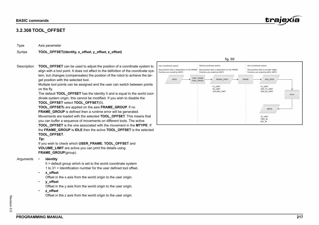
BASIC
PROG 217
Revision 5.0
3.2.3/i
fig. 69/i
Type
Synta
WORLD_DPOS
FE_LIMITAXIS_FS_LIMITAXIS_RS_LIMIT
LIMITLIMITUME_LIMIT
stem
FRAME AXIS_DPOS
Drive
MPOS
FE_LIMITFWD_INREV_IN
dependant on the FRAME by UNITS
Axis coordinate system
Raw position data is encoder edgesPositions are scaled by AXIS_UNITS
Descr
Argum
commands
RAMMING MANUAL
08 TOOL_OFFSET
Axis parameter
x TOOL_OFFSET(identity, x_offset, y_offset, z_offset)
DPOS USER_FRAMETOOL_OFFSET
User coordinate system
FS_RS_VOL
World coordinate sy
Raw position data is dependant on the FRAMEPositions are scaled by UNITS
Raw position data isPositions are scaled
iption TOOL_OFFSET can be used to adjust the position of a coordinate system to align with a tool point. It does not affect to the definition of the coordinate sys-tem, but changes (compensates) the position of the robot to achieve the tar-get position with the selected tool. Multiple tool points can be assigned and the user can switch between points on the fly.The default TOOL_OFFSET has the identity 0 and is equal to the world coor-dinate system origin, this cannot be modified. If you wish to disable the TOOL_OFFSET select TOOL_OFFSET(0).TOOL_OFFSETs are applied on the axis FRAME_GROUP. If no FRAME_GROUP is defined then a runtime error will be generated.Movements are loaded with the selected TOOL_OFFSET. This means that you can buffer a sequence of movements on different tools. The active TOOL_OFFSET is the one associated with the movement in the MTYPE. If the FRAME_GROUP is IDLE then the active TOOL_OFFSET is the selected TOOL_OFFSET.Tip:If you wish to check which USER_FRAME, TOOL_OFFSET and VOLUME_LIMIT are active you can print the details using FRAME_GROUP(group).
ents • identity0 = default group which is set to the world coordinate system1 to 31 = Identification number for the user defined tool offset.
• x_offsetOffset in the x axis from the world origin to the user origin.
• y_offsetOffset in the y axis from the world origin to the user origin.
• z_offsetOffset in the z axis from the world origin to the user origin.
BASIC
PROG 218
Revision 5.0
TOOL_/i
3.2.3/i
/i
Exam
See a
Type
Synta
Descr
Bit
0
1
2 - 7
8
9
e
it in the system)
too many units connected
device in the system)
unit in the system)
ice in the system)
er contains the torque reference value which will be motor.K-II axes, the available range is [-1073741824, corresponds to a torque range [-Peak torque, Peak
2-KS02 axes, the available range is [-5000, 5000], which que range [-500.0%, 500.0%]. limited by using the OUTLIMIT parameter.
ference is depending on the servo motor.
0
IMIT.
commands
RAMMING MANUAL
OFFSET
09 SYSTEM_ERROR
/i
3.2.310 T_REF/i
ple A tool is rotated 45degrees about the y axis and has an offset of 20mm in the x direction, 30mm in the y direction and 300mm in the z direction. The pro-grammer wants to move the tool forward on its axis so a TOOL_OFFSET is applied to adjust the position to the tool tip, then a USER_FRAME is appliedto allow programming about the tool axis.'Configure USER_FRAME and TOOL_OFFSETFRAME_GROUP(0,0,0,1,2)USER_FRAME(1, 20, 30, 300, 0, PI/4, 0)TOOL_OFFSET(1, 20, 30, 300)'Select tool and frame and start motion.USER_FRAME(1)TOOL_OFFSET(1)BASE(2)FORWARD
lso USER_FRAME, FRAME_GROUP
System parameter (read only)
x SYSTEM_ERROR
iption The SYSTEM_ERROR parameter contains system errors that occurred in the TJ2 system since the last time it was initialized. The bits in the SYSTEM_ERROR parameter are given in the table below.
Description
SRAM memory error
Battery low error
Reserved for future use
Configuration unit error (Any unit in the system)
Configuration device error (Any device in the system)
10 - 15 Reserved for future us
16 Unit lost error (Any un
17 Terminator not fitted /
18 Device lost error (Any
19 Unsupported unit (Any
20 Device error (Any dev
Arguments N/A.
Example No example.
See also N/A
Type Axis parameter
Syntax T_REFDAC
Description The T_REF parametapplied to the servo For MECHATROLIN1073741824], whichtorque].For EtherCAT and TJcorresponds to a torThese ranges can beThe actual torque re
Arguments N/A
Example T_REF AXIS(0)=100
See also AXIS, S_REF, OUTL
Bit Description
BASIC
PROG 219
Revision 5.0
3.2.3/i
Type
Synta
Descr
Argum
Exam
Value
0
120
250
370
470
530
550
ll print the value at location 1000.000)
L, NEW, SCOPE, TSIZE, VR.
only)
INTER
OINTER parameter it is possible to determine which tion is currently being used by the CAM allowing the user ta into previously processed TABLE location ready for the is ideal for allowing a technician to finely tune a complex recipes on the fly whilst running. TABLE_POINTER ble location that the CAM function is using. The returned table location and divides up the interpolated distance and next TABLE location to indicate exact location.
M profile is loaded into TABLE location 1000 and is setup d to a master axis 1. A copy of the CAM table is added at alogue input is then read and the CAM TABLE value is ble pointer is on the next value.
commands
RAMMING MANUAL
11 TABLE /i
/i
3.2.312 TABLE_POINTER/i
System command
x TABLE(address, value {, value})TABLE(address)
iption The TABLE command loads data to and reads data from the TABLE array. The TABLE has a maximum length of 500000 elements. The TABLE values are float-ing-point numbers with fractions. The TABLE can also be used to hold informa-tion, as an alternative to variables. The TABLE command has two forms.• TABLE(address, value{, value}) writes a sequence of values to the
TABLE array. The location of the first element to write is specified by address. The sequence can have a maximum length of 20 elements.
• TABLE(address) returns the TABLE value at the entry specified by address.
A value in the TABLE can be read-only if a value of that number or higher has been previously written to the TABLE. For example, printing TABLE(1001) will produce an error message if the highest TABLE location previously written to the TABLE is location 1000. The total TABLE size is indicated by the TSIZE parameter. Note that this value is one more than the highest defined element address.The TABLE can be deleted with by using DEL "TABLE" or NEW "TABLE" on the command line.Notes:• Applications like the CAM command, CAMBOX command and the
SCOPE command in Trajexia Studio all use the same TABLE as the data area. Do not use the same data area range for different purposes.
• The TABLE and VR data can be accessed from all different running tasks. To avoid problems of two program tasks writing unexpectedly to one global variable, write the programs in such a way that only one pro-gram writes to the global variable at a time.
ents • addressThe first location in the TABLE to read or write. Range: [0,499999]
• valueThe value to write at the given location and at subsequent locations.
ple TABLE(100,0,120,250,370,470,530,550)The above line loads an internal table as below.
Table entry
100
101
102
103
104
105
106
Example The following line wi>> PRINT TABLE(1
See also CAM, CAMBOX, DE
Type Axis parameter (read
Syntax value = TABLE_PO
Description Using the TABLE_PTABLE memory locato load new CAM danext CAM cycle. Thisprocess, or changingreturns the current tanumber contains thebetween the current
Arguments N/A
Example In this example a CAon axis 0 and is linkelocation 100. The Anupdated when the ta
BASIC
PROG 220
Revision 5.0
ress, number_of_points, format)
LE points starting at the number specified. There is only d at the moment, and that is comma delimited text.S is provided mainly for Trajexia Studio to allow for fast ABLE values.
irst point to be returnedints points to be returned
st (0 = comma delimited text)
n
turns the tangent of the expression. The expression is ians.
expression.
commands
RAMMING MANUAL
3.2.313 TABLEVALUES/i
3.2.314 TAN/i
'CAM Pointer demo' store the live table pointsTABLE(1000,0,0.8808,6.5485,19.5501,39.001,60.999,80.4499,93.4515)TABLE(1008,99.1192,100)' Store another copy of original pointsTABLE(100,0,0.8808,6.5485,19.5501,39.001,60.999,80.4499,93.4515)TABLE(108,99.1192,100)' Initialise axesBASE(0)WDOG=ONSERVO=ON' Set up CAMCAMBOX(1000,1009,10,100,1, 4, 0)'Start Master axisBASE(1)SERVO=ONSPEED=10FORWARD'Read Analog input and scale CAM based on inputpointer=0WHILE 1 'Read Analog Input (Answer 0-10) scale=AIN(32)*0.01 'Detects change in table pointer IF INT(TABLE_POINTER)<>pointer THEN pointer=INT(TABLE_POINTER) 'First value so update last value IF pointer=1000 THEN TABLE(1008,(TABLE(108)*scale)) 'Second Value, so must update First & Last but 1 value ELSEIF pointer=1001 THEN TABLE(1000,(TABLE(100)*scale)) TABLE(1009,(TABLE(109)*scale)) 'Update previous value ELSE TABLE(pointer-1, (TABLE(pointer-901)*scale)) ENDIF ENDIFWEND
See also CAM, TABLE
Type System command
Syntax TABLEVALUES(add
Description Returns a list of TABone format supporteNote: TABLEVALUEaccess to banks of T
Arguments • addressNumber of the f
• number_of_poTotal number of
• formatFormat for the li
Example No example.
See also N/A
Type Mathematical functio
Syntax TAN(expression)
Description The TAN function reassumed to be in rad
Arguments • expressionAny valid BASIC
Example >> print TAN(PI/4)1.0000
See also N/A
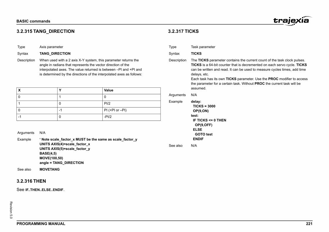
BASIC
PROG 221
Revision 5.0
3.2.3/i
/i
/i
3.2.3
See I
Type
Synta
Descr
X
0
1
0
-1
Argum
Exam
See a
er contains the current count of the task clock pulses. unter that is decremented on each servo cycle. TICKS ad. It can be used to measure cycles times, add time
n TICKS parameter. Use the PROC modifier to access ertain task. Without PROC the current task will be
N
commands
RAMMING MANUAL
15 TANG_DIRECTION
16 THEN
F..THEN..ELSE..ENDIF.
3.2.317 TICKS/i
Axis parameter
x TANG_DIRECTION
iption When used with a 2 axis X-Y system, this parameter returns theangle in radians that represents the vector direction of theinterpolated axes. The value returned is between –PI and +PI andis determined by the directions of the interpolated axes as follows:
Y Value
1 0
0 PI/2
-1 PI (+PI or –PI)
0 -PI/2
ents N/A
ple ‘ Note scale_factor_x MUST be the same as scale_factor_yUNITS AXIS(4)=scale_factor_xUNITS AXIS(5)=scale_factor_yBASE(4,5)MOVE(100,50)angle = TANG_DIRECTION
lso MOVETANG
Type Task parameter
Syntax TICKS
Description The TICKS parametTICKS is a 64-bit cocan be written and redelays, etc.Each task has its owthe parameter for a cassumed.
Arguments N/A
Example delay: TICKS = 3000 OP(9,ON)test: IF TICKS <= 0 THE OP(9,OFF) ELSE GOTO test ENDIF
See also N/A
BASIC
PROG 222
Revision 5.0
3.2.3/i
3.2.3/i
3.2.3
See F
Type
Synta
Descr
Argum
Exam
See a
Type
Synta
Descr
Argum
Exam
See a
-only)
n at output of frame transformation. TRANS_DPOS is OS on each axis. The frame transformation is therefore each axis. For some machinery configurations it can be me transformation which is not 1:1, these are typically botic arms or machines with parasitic motions on the
rmations have to be specially written in the C language the controller. It is essential to contact OMRON if you
transformations.
and starts a previously set up SCOPE command. uses TRIGGER automatically for its oscilloscope func-
commands
RAMMING MANUAL
18 TIME
19 TIME$
20 TO
OR..TO..STEP..NEXT.
3.2.321 TRANS_DPOS/i
3.2.322 TRIGGER/i
System parameter
x TIME
iption Sets and returns the time from the real time clock. The time returned as an integer is the number of seconds since midnight 00:00:00.
ents N/A
ple Sets the real time clock in 24 hour format; hh:mm:ss’Set the real time clock>>TIME = 13:20:00 >> PRINT TIME>> 48002.0000Print executed after 2 seconds
lso N/A
System command
x TIME$
iption Prints the current time as defined by the real time clock as a string in 24-hour format.
ents N/A
ple When the time is 13:20:00>> PRINT TIME$>> 13:20:00
lso N/A
Type Axis parameter (read
Syntax TRANS_DPOS
Description Axis demand positionormally equal to DPequivalent to 1:1 for useful to install a framachines such as roaxes. Frame transfoand downloaded intowant to install frame
Arguments N/A
Example No example.
See also FRAME.
Type System command
Syntax TRIGGER
Description The TRIGGER commNote: Trajexia Studiotion.
Arguments N/A
Example No example.
See also SCOPE.
BASIC
PROG 223
Revision 5.0
3.2.3/i
3.2.3/i
Type
Synta
Descr
Argum
Exam
See a
Type
Synta
Descr
Argum
Exam
See a
returns the numerical value -1.
)
e ON"
ead-only)
r returns the size of the TABLE array, which is one more hest defined TABLE element.hen the TABLE array is deleted using DEL "TABLE" or e command line.
le assumes that no location higher than 1000 has been array.0)
commands
RAMMING MANUAL
23 TROFF
24 TRON
3.2.325 TRUE/i
3.2.326 TSIZE/i
Program command
x TROFF [ "program_name" ]
iption The TROFF command suspends a trace at the current line and resumes nor-mal program execution for the program specified with program_name. The program name can also be specified without quotes. If the program name is omitted, the selected program will be assumed.
ents • program_nameThe name of the program for which to suspend tracing.
ple >> TROFF "lines"
lso SELECT, TRON.
Program command
x TRON
iption The TRON command creates a breakpoint in a program that will suspend pro-gram execution at the line following the TRON command. The program can then for example be executed one line at a time using the STEPLINE command.Notes:• Program execution can be resumed without using the STEPLINE com-
mand by executing the TROFF command.• The trace mode can be stopped by issuing a STOP or HALT command.
ents N/A
ple TRONMOVE(0,10)MOVE(10,0)TRONMOVE(0,-10)MOVE(-10,0)
lso SELECT, TROFF.
Type Constant (read-only)
Syntax TRUE
Description The TRUE constant
Arguments N/A
Example test: t = IN(0) AND IN(2 IF t = TRUE THEN PRINT "Inputs ar ENDIF
See also N/A
Type System parameter (r
Syntax TSIZE
Description The TSIZE parametethan the currently higTSIZE is reset to 0 wNEW "TABLE" on th
Arguments N/A
Example The following exampwritten to the TABLE>> TABLE(1000,340>> PRINT TSIZE1001.0000
See also DEL, NEW, TABLE.
BASIC
PROG 224
Revision 5.0
3.2.3/i
3.2.3/i
Type
Synta
Descr
Argum
Exam
See a
Type
Synta
Descr
Argum
Exam
See a
ead only)
ns a bitfield indicating which units are in error where each a unit.
ber)
mand will initialise communication with all drives attached will assign the initial ATYPEs for connected drives. This when drives are powered-on or attached after startup of
cution, this command returns -1. If this command fails, it
ll be assigned when a TJ2-KS02 connector is not connected hen the connected Servo Drive is not powered. The ATYPE d to verify if the Servo Drive has been detected.
e 0 to 6, with 0 being the unit immediately to the right of
le shows a succesful initialisation of a TJ2-KS02,
T(0)
commands
RAMMING MANUAL
27 UNIT_CLEAR
28 UNIT_DISPLAY
3.2.329 UNIT_ERROR/i
3.2.330 UNIT_INIT/i
System command
x UNIT_CLEAR [SLOT(unit_number)]
iption This command clears the error of the specified unit.
ents • unit_numberUnit numbers are 0 to 6, with 0 being the unit immediately to the right of the TJ2-MC__.
ple N/A
lso UNIT_ERROR
System parameter
x UNIT_DISPLAY [SLOT(unit_number)] = value
iption The UNIT_DISPLAY parameter enables different data to be displayed bythe LEDs on the front cover of the TJ2-ECT__ unit. LEDs affected by thisparameter setting are four yellow LEDs showing the input status. The default value of this parameter on start-up is 0.Set value to the following to define the function of the LEDs:0 = the LEDs show the status of the first 4 inputs1 = the LEDs show the status of the last 4 inputs
ents • unit_numberUnit numbers are 0 to 6, with 0 being the unit immediately to the right of the TJ2-MC__.
ple The following example causes the 4 yellow LEDs of the TJ2-ECT__ in slot 1 (second extension unit) to show the status of inputs 4, 5, 6 and 7.UNIT_DISPLAY SLOT(1) = 1
lso N/A
Type System parameter (r
Syntax UNIT_ERROR
Description This parameter returbit corresponds with
Arguments N/A
Example N/A
See also UNIT_CLEAR
Type System command
Syntax UNIT_INIT(unit_num
Description The UNIT_INIT comto the TJ2-KS02 andcommand is requiredthe controller.Upon successful exereturns 0.Note: a virtual axis wito a Servo Drive, or wparameter can be use
Arguments • unit_numberUnit numbers arthe TJ2-MC__.
Example The following exampresulting in 3 axes:>> PRINT UNIT_INIKS02[0]: 0 1 2 -1.0000
See also N/A
BASIC
PROG 225
Revision 5.0
3.2.3/i
3.2.3
See L
3.2.3
See R
Type
Synta
Descr
Argum
Exam
See a
commands
RAMMING MANUAL
31 UNITS
32 UNLOCK
OCK.
33 UNTIL
EPEAT..UNTIL.
Axis parameter
x UNITS
iption The UNITS parameter contains the unit conversion factor. The unit conversion factor enables the user to define a more convenient user unit like m, mm or motor revolutions by specifying the amount of encoder edges to include in a user unit.Axis parameters like speed, acceleration, deceleration and the Axis com-mands are specified in these user units.Note: The UNITS parameter can be any non-zero value, but it is recom-mended to design systems with an integer number of encoder pulses per user unit. Changing UNITS will affect all axis parameters which are dependent on UNITS in order to keep the same dynamics for the system.Note: The Gear ratio inside the MECHATROLINK-II and EtherCAT servo drives affects the resolution of the motor encoder.
ents N/A
ple A leads crew arrangement has a 5mm pitch and a 1,000-pulse/rev encoder. The units must be set to allow moves to be specified in mm.The 1,000 pulses/rev will generate 1,000 x 4 = 4,000 edges/rev. One rev is equal to 5mm. Therefore, there are 4,000/5 = 800 edges/mm. UNITS is thus set as following.>> UNITS = 1000*4/5
lso AXIS, ENCODER_RATIO.
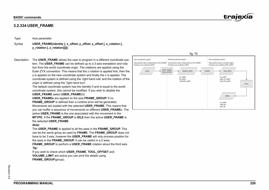
BASIC
PROG 226
Revision 5.0
3.2.3/i
fig. 70/i
Type
Synta
WORLD_DPOS
FE_LIMITAXIS_FS_LIMITAXIS_RS_LIMIT
LIMITLIMIT
LUME_LIMIT
ystem
FRAME AXIS_DPOS
Drive
MPOS
FE_LIMITFWD_INREV_IN
s dependant on the FRAME by UNITS
Axis coordinate system
Raw position data is encoder edgesPositions are scaled by AXIS_UNITS
Descr
commands
RAMMING MANUAL
34 USER_FRAME
Axis parameter
x USER_FRAME(identity [, x_offset, y_offset, z_offset [, x_rotation [, y_rotation [, z_rotation]]]])
DPOS USER_FRAMETOOL_OFFSET
User coordinate system
FS_RS_VO
World coordinate s
Raw position data is dependant on the FRAMEPositions are scaled by UNITS
Raw position data iPositions are scaled
iption The USER_FRAME allows the user to program in a different coordinate sys-tem. The USER_FRAME can be defined up to a 3-axis translation and rota-tion from the world coordinate origin. The rotations are applied using the Euler ZYX convention. This means that the z rotation is applied first, then the y is applied on the new coordinate system and finally the x is applied. The coordinate system is defined using the ‘right hand rule’ and the rotation of the origin is defined using the ‘right hand turn’.The default coordinate system has the identity 0 and is equal to the world coordinate system, this cannot be modified. If you wish to disable the USER_FRAME select USER_FRAME(0).USER_FRAMEs are applied on the axis FRAME_GROUP. If no FRAME_GROUP is defined then a runtime error will be generated.Movements are loaded with the selected USER_FRAME. This means that you can buffer a sequence of movements on different USER_FRAMEs. The active USER_FRAME is the one associated with the movement in the MTYPE. If the FRAME_GROUP is IDLE then the active USER_FRAME is the selected USER_FRAME.Note:The USER_FRAME is applied to all the axes in the FRAME_GROUP. This can be the same group as used by FRAME. The FRAME_GROUP does not have to be 3 axis, however the USER_FRAME will only process position for the axes in the FRAME_GROUP. It can be useful in a 2 axes FRAME_GROUP to perform a USER_FRAME rotation about the third axis.Tip:If you wish to check which USER_FRAME, TOOL_OFFSET and VOLUME_LIMIT are active you can print the details using FRAME_GROUP(group).
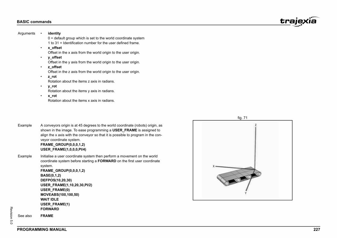
BASIC
PROG 227
Revision 5.0
USER/i
fig. 71/i
Argum
Exam
Exam
See a
commands
RAMMING MANUAL
_FRAME
ents • identity0 = default group which is set to the world coordinate system1 to 31 = Identification number for the user defined frame.
• x_offsetOffset in the x axis from the world origin to the user origin.
• y_offsetOffset in the y axis from the world origin to the user origin.
• z_offsetOffset in the z axis from the world origin to the user origin.
• z_rotRotation about the items z axis in radians.
• y_rotRotation about the items y axis in radians.
• x_rotRotation about the items x axis in radians.
ple A conveyors origin is at 45 degrees to the world coordinate (robots) origin, as shown in the image. To ease programming a USER_FRAME is assigned to align the x axis with the conveyor so that it is possible to program in the con-veyor coordinate system.FRAME_GROUP(0,0,0,1,2)USER_FRAME(1,0,0,0,PI/4)
ple Initialise a user coordinate system then perform a movement on the world coordinate system before starting a FORWARD on the first user coordinate system.FRAME_GROUP(0,0,0,1,2)BASE(0,1,2)DEFPOS(10,20,30)USER_FRAME(1,10,20,30,PI/2)USER_FRAME(0)MOVEABS(100,100,50)WAIT IDLEUSER_FRAME(1)FORWARD
lso FRAME
BASIC
PROG 228
Revision 5.0
3.2.3/i
Type
Synta
Descr
Argum
Exam
See a
commands
RAMMING MANUAL
35 USER_FRAMEB
Axis parameter
x USER_FRAMEB(identity)
iption USER_FRAMEB is only used with SYNC. It defines the new USER_FRAME to resynchronise to when performing the SYNC(20) operation. When the resynchronisation is complete USER_FRAMEB is the active USER_FRAME. USER_FRAMEB selects one of the defined USER_FRAMEs.
ents • identity0 = default group which is set to the world coordinate system1 to 31 = Identification number for the user defined frame.
ple The robot must pick up the components from one conveyor and place them on a second conveyor which is in a different USER_FRAME.WHILE(running) USER_FRAMEB(conv1) REGIST(20,0,0,0,0) AXIS(10) WAIT UNTIL MARK AXIS(10) SYNC(1, 1000, REG_POS, 10, sen_xpos , conv1_yoff) WAIT UNTIL SYNC_CONTROL AXIS(0)=3 'Now synchronised GOSUB pick USER_FRAMEB(conv2) SYNC(20, 1000, place_pos, 11, conv2_xoff, conv2_yoff) WAIT UNTIL SYNC_CONTROL AXIS(0)=3 'Now synchronised GOSUB place SYNC(4, 500) place_pos = place_pos + 100WEND
lso SYNC, USER_FRAME
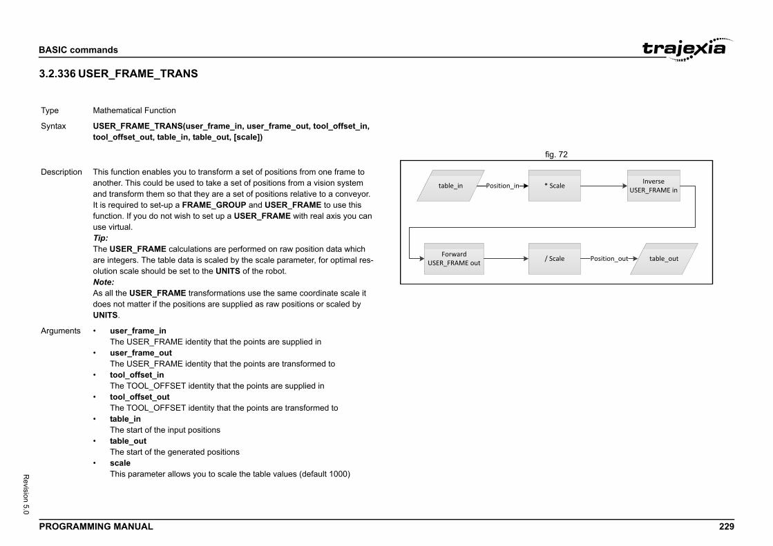
BASIC
PROG 229
Revision 5.0
3.2.3/i
fig. 72/i
Type
Synta
* Scale Inverse USER_FRAME in
/ Scale table_outPosition_out
Descr
Argum
commands
RAMMING MANUAL
36 USER_FRAME_TRANS
Mathematical Function
x USER_FRAME_TRANS(user_frame_in, user_frame_out, tool_offset_in, tool_offset_out, table_in, table_out, [scale])
table_in Position_in
Forward USER_FRAME out
iption This function enables you to transform a set of positions from one frame to another. This could be used to take a set of positions from a vision system and transform them so that they are a set of positions relative to a conveyor.It is required to set-up a FRAME_GROUP and USER_FRAME to use this function. If you do not wish to set up a USER_FRAME with real axis you can use virtual.Tip:The USER_FRAME calculations are performed on raw position data which are integers. The table data is scaled by the scale parameter, for optimal res-olution scale should be set to the UNITS of the robot.Note:As all the USER_FRAME transformations use the same coordinate scale it does not matter if the positions are supplied as raw positions or scaled by UNITS.
ents • user_frame_inThe USER_FRAME identity that the points are supplied in
• user_frame_outThe USER_FRAME identity that the points are transformed to
• tool_offset_inThe TOOL_OFFSET identity that the points are supplied in
• tool_offset_outThe TOOL_OFFSET identity that the points are transformed to
• table_inThe start of the input positions
• table_outThe start of the generated positions
• scaleThis parameter allows you to scale the table values (default 1000)
BASIC
PROG 230
Revision 5.0
3.2.3/i
3.2.3/i
Exam
See a
Type
Synta
Descr
Argum
Exam
See a
Type
Synta
Descr
Argum
Exam
See a
meter contains the speed feed forward gain. The speed contribution is calculated by multiplying the change in the VFF_GAIN parameter value. The default value is 0.
orward gain to a system decreases the Following Error reasing the output proportionally with the speed.id any instability the servo gains should be changed only FF.
V_GAIN, P_GAIN.
commands
RAMMING MANUAL
37 VECTOR_BUFFERED
38 VERSION
3.2.339 VFF_GAIN/i
ple USER_FRAME(vision) has been configured to the vision system relative to the robot origin. The conveyor has been configures in USER_FRAME(con-veyor). To use the vision system positions on the conveyor USER_FRAME they must be transformed through USER_FRAME_TRANS.USER_FRAME_TRANS(vision, conveyor, 0, 0, 200,300)
lso USER_FRAME
Axis parameter (read only)
x VECTOR_BUFFERED
iption This holds the total vector length of the buffered moves. It is effectively the amount the system can assume is available for deceleration.
ents N/A
ple No example.
lso ENDMOVE_BUFFER, MOVES_BUFFERED
System parameter (read-only)
x VERSION
iption The VERSION parameter returns the current firmware version number of the current system installed in the TJ2-MC__.
ents N/A
ple >> PRINT VERSION1.6100
lso N/A
Type Axis parameter
Syntax VFF_GAIN
Description The VFF_GAIN parafeed forward output demand position withAdding speed feed fduring a move by incNote: In order to avowhen the SERVO=O
Arguments N/A
Example No example.
See also D_GAIN, I_GAIN, O
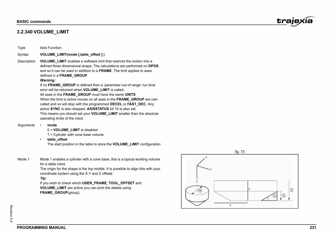
BASIC
PROG 231
Revision 5.0
3.2.3/i
fig. 73/i
Type
Synta
Descr
Argum
Mode
commands
RAMMING MANUAL
40 VOLUME_LIMIT
Axis Function
x VOLUME_LIMIT(mode [,table_offset ] )
iption VOLUME_LIMIT enables a software limit that restricts the motion into a defined three dimensional shape. The calculations are performed on DPOS and so it can be used in addition to a FRAME. The limit applies to axes defined in a FRAME_GROUP.Warning:If no FRAME_GROUP is defined then a ‘parameter out of range’ run time error will be returned when VOLUME_LIMIT is called.All axes in the FRAME_GROUP must have the same UNITSWhen the limit is active moves on all axes in the FRAME_GROUP are can-celled and so will stop with the programmed DECEL or FAST_DEC. Any active SYNC is also stopped. AXISSTATUS bit 15 is also set.This means you should set your VOLUME_LIMIT smaller than the absolute operating limits of the robot.
ents • mode0 = VOLUME_LIMIT is disabled1 = Cylinder with cone base volume
• table_offsetThe start position in the table to store the VOLUME_LIMIT configuration
1 Mode 1 enables a cylinder with a cone base, this is a typical working volume for a delta robot.The origin for the shape is the top middle. It is possible to align this with your coordinate system using the X,Y and Z offsetsTip:If you wish to check which USER_FRAME, TOOL_OFFSET and VOLUME_LIMIT are active you can print the details using FRAME_GROUP(group).
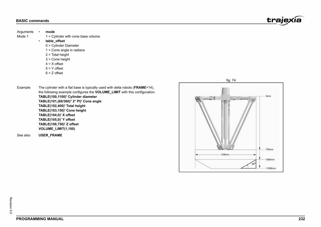
BASIC
PROG 232
Revision 5.0
fig. 74/i
ArgumMode
Exam
See a
commands
RAMMING MANUAL
ents1
• mode1 = Cylinder with cone base volume
• table_offset0 = Cylinder Diameter1 = Cone angle in radians2 = Total height3 = Cone height4 = X offset5 = Y offset6 = Z offset
ple The cylinder with a flat base is typically used with delta robots (FRAME=14), the following example configures the VOLUME_LIMIT with this configuration.TABLE(100,1100)' Cylinder diameterTABLE(101,(60/360)* 2* PI)' Cone angleTABLE(102,400)' Total heightTABLE(103,150)' Cone heightTABLE(104,0)' X offsetTABLE(105,0)' Y offsetTABLE(106,750)' Z offsetVOLUME_LIMIT(1,100)
lso USER_FRAME
BASIC
PROG 233
Revision 5.0
3.2.3/i
3.2.3/i
Type
Synta
Descr
Argum
Exam
See a
Type
Synta
Descr
Argum
ple, the value 1.2555 is placed into VR variable 15. The sed to name the global variable locally:
10 put down positions in a row. Each position may at pty. VR(101) to VR(110) are used to hold an array of ten
al that the positions are full (1) or empty (0). The gantry the first free position. Part of the program to achieve this
ove to first put down positionO 110) THEN GOSUB load is spacing between positions
ns are full"= ON
osition and mark array
cked up by a battery so the program here could be state of the machine when the power is off. It would of to provide a means of resetting completely following
5) to VR(0) multiplied by axis 1 measured positionOS AXIS(1)
_BIT, SET_BIT, TABLE.
commands
RAMMING MANUAL
41 VP_SPEED
42 VR
Axis parameter (read-only)
x VP_SPEED
iption The VP_SPEED parameter contains the speed profile speed in user units/s. The speed profile speed is an internal speed which is accelerated and decel-erated as the movement is profiled.
ents N/A
ple ' Wait until at command speedMOVE(100)WAIT UNTIL SPEED = VP_SPEED
lso AXIS, MSPEED, UNIT_INIT.
System command
x VR(address)
iption The VR command reads or writes the value of a global (VR) variable. These VR variables hold real numbers and can be easily used as an element or as an array of elements. The TJ2-MC__ has in total 64000 VR variables.The VR variables can be used for several purposes in BASIC programming. The VR variables are globally shared between tasks and can be used for communications between tasks. VR variable memory area is battery backed, so all VR variables retain their values between power upsNotes: • The TABLE and VR data can be accessed from all different running
tasks. To avoid problems of two program tasks writing unexpectedly to one global variable, write the programs in such a way that only one pro-gram writes to the global variable at a time.
ents • addressThe address of the VR variable. Range: [0,63999].
Example In the following examlocal variable val is uval = 15VR(val) = 1.2555
Example A transfer gantry hasany time be full or em1 ' s and 0 ' s to signputs the load down inwould be as follows:movep: MOVEABS(115) ' M FOR VR(0) = 101 T IF (VR(VR(0)) = 0 MOVE(200) ' 200 NEXT VR(0) PRINT "All positio WAIT UNTIL IN(3) GOTO movep
load: ' Put load in p OP(15,OFF) VR(VR(0)) = 1 RETURNThe variables are badesigned to store thecourse be necessarymanual intervention.
Example loop: ' Assign VR(6 VR(65) = VR(0)*MP PRINT VR(65) GOTO loop
See also CLEAR_BIT, READ
BASIC
PROG 234
Revision 5.0
3.2.3/i
3.2.3/i
Type
Synta
Descr
Argum
Exam
See a
Type
Synta
Descr
Argum
Exam
See a
mand suspends program execution until the base axis g its current move and any buffered move. The com-ed in a program. WAIT IDLE works on the default basis unless AXIS is used to specify a temporary base axis. of WAIT IDLE does not necessarily mean that the axis servo motor system.
"is printed at the end of the movement.
=0finished"is printed, most of the times BEFORE the movement s, when the movement is finished.
d motion sequence work in parallel and unsynchronized. can occur before the movement is loaded into the buffer. es MOVE(1000) but the movement is not loaded to the f the next "motion sequence" so when you check
cause the movement HAS NOT STARTED YET, not ed.
D.
ommand specifically designed to wait until the nt has been finished so, it handles the delay
evious command is executed in the program d is correctly loaded in the motion buffer.
commands
RAMMING MANUAL
43 VRSTRING
44 WA
3.2.345 WAIT IDLE/i
System command
x VRSTRING(vr_start)
iption Combines the contents of an array of VR() variables so that they can be printed as a text string. All printable characters will be output and the string will terminate at the first null character found. (i.e. VR(n) contains 0)
ents • vr_startnumber of first VR() in the character array.
ple PRINT #5,VRSTRING(100)
lso N/A
System command
x WA(time)
iption The WA command pauses program execution for the number of milliseconds specified for time. The command can only be used in a program.
ents • timeThe number of milliseconds to hold program execution.
ple The following lines would turn ON output 7 two seconds after turn-ing off output 1.OP(1,OFF)WA(2000)OP(7,ON)
lso N/A
Type System command
Syntax WAIT IDLE
Description The WAIT IDLE comhas finished executinmand can only be usaxis (set with BASE)Note: The executionwill be stationary in a
Arguments N/A
Example MOVE(1000)WAIT IDLEPRINT "Move DoneThe print statement
Example MOVE(1000)WAIT UNTIL MTYPEPRINT "Movement The print statement starts, and sometime
Explanation Motion programs anOne complete cycle The program executbuffer until the start oMTYPE=0, it is 0 bebecause it has finish
See also AXIS, WAIT LOADE
NOTEWAIT IDLE is a cprevious movemefrom when the pruntil the comman
BASIC
PROG 235
Revision 5.0
3.2.3/i
3.2.3/i
Type
Synta
Descr
Argum
Exam
See a
Type
Synta
Descr
Argum
program waits until the measured position on axis 0 en starts a movement on axis 1. AXIS(0)>150
luated can be as complex as you like provided they fol-r example:
AXIS(2) <= 0 OR IN(1) = ONd wait until the demand position of axis 2 is less than or is on.
ter contains the software switch which enables the Servo (Servo on) input signal. The enabled Servo Drive will tor depending on the speed and torque reference values. d on and off under program control or on the Command
automatically be disabled when a MOTION_ERROR or occurs when the AXISSTATUS state for one of the
RORMASK setting. In this case the software switch ed off, the MOTION_ERROR parameter will have value the ERROR_AXIS parameter will contain the number of the error.
ed on, an EtherCAT Servo Drive will make the transition n” state to the “Operation enabled” state. Only after the “Operation enabled” state it can process motion com-is advisable to check if the Servo Drive is in that state. follows:_STATUS AND 4SIC program will wait until bit 2 is set, which reflects the state.
commands
RAMMING MANUAL
46 WAIT LOADED
47 WAIT UNTIL
3.2.348 WDOG/i
System command
x WAIT LOADED
iption The WAIT LOADED command suspends program execution until the base axis has no moves buffered ahead other than the currently executing move. The command can only be used in a program.This is useful for activating events at the beginning of a move, or at the end when multiple moves are buffered together.WAIT LOADED works on the default basis axis (set with BASE) unless AXIS is used to specify a temporary base axis.
ents N/A
ple ' Switch output 8 ON at start of MOVE(500) and OFF at endMOVE(800)MOVE(500)WAIT LOADEDOP(8,ON)MOVE(400)WAIT LOADEDOP(8,OFF)
lso AXIS, WAIT IDLE
System command
x WAIT UNTIL condition
iption The WAIT UNTIL command repeatedly evaluates the condition until it is TRUE. After this program execution will continue. The command can only be used in a program.
ents • conditionAny valid BASIC logical expression.
Example In this example, the exceeds 150, and thWAIT UNTIL MPOSMOVE(100) AXIS(1)
Example The expressions evalow BASIC syntax, foWAIT UNTIL DPOSThe above line woulequal to 0 or input 1
See also N/A
Type System parameter
Syntax WDOG
Description The WDOG parameDrive using the RUNcontrol the servo moWDOG can be turneLine Terminal.The Servo Drive willoccurs. A motion erraxes matches the ER(WDOG) will be turndifferent than 0 and the first axis to have
Arguments N/A
Example When WDOG is turnfrom the “Switched oServo Drive is in themands. Therefore it This can be done asWAIT UNTIL DRIVEWith this line the BA“Operation enabled”
BASIC
PROG 236
Revision 5.0
3.2.3/i
See a
Type
Synta
Descr
Argum
Exam
See a
ion
xpression2
OR) operator performs the logical XOR function between f the integer parts of two valid BASIC expressions.ction between two bits is defined as in the table below.
Result
0
1
1
0
expression.
expression.
rator and so the binary action taking place is as follows: 11000. The result is therefore 24.
commands
RAMMING MANUAL
49 WHILE..WEND
3.2.350 XOR/i
/i
/i
lso AXIS_FS_LIMIT, ERROR_AXIS, ERRORMASK, MOTION_ERROR, SERVO.
Program control command
x WHILE condition commandsWEND
iption The WHILE ... WEND structure allows the program segment between the WHILE and the WEND statement to be repeated a number of times until the condition becomes FALSE. In that case program execution will continue after WEND.Note: WHILE ... WEND loops can be nested without limit.
ents • conditionAny valid logical BASIC expression.
ple WHILE IN(12) = OFF MOVE(200) WAIT IDLE OP(10,OFF) MOVE(-200) WAIT IDLE OP(10,ON)WEND
lso FOR..TO..STEP..NEXT, REPEAT..UNTIL
Type Mathematical operat
Syntax expression1 XOR e
Description The XOR (eXclusivecorresponding bits oThe logical XOR fun
Bit 1 Bit 2
0 0
0 1
1 0
1 1
Arguments • expression1Any valid BASIC
• expression2Any valid BASIC
Example VR(0)=10 XOR 18The XOR is a bit ope01010 XOR 10010 =
See also N/A
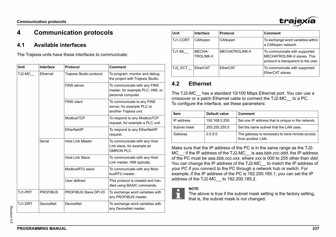
Comm
PROG 237
Revision 5.0
4
4.1The T/i
rd 10/100 Mbps Ethernet port. You can use a t cable to connect the TJ2-MC__ to a PC.t these parameters:
s of the PC is in the same range as the TJ2- TJ2-MC__ is aaa.bbb.ccc.ddd, the IP address
cc.xxx, where xxx is 000 to 255 other than ddd.ss of the TJ2-MC__ to match the IP address of PC through a network hub or switch. For the PC is 192.200.185.1, you can set the IP 192.200.185.2.
Unit
TJ2-M
TJ1-P
TJ1-D
open To exchange word variables within a CANopen network.
HATROLINK-II To communicate with supported MECHATROLINK-II slaves. This protocol is transparent to the user.
rCAT To communicate with supported EtherCAT slaves.
Comment
0 Set one IP address that is unique in the network.
0 Set the same subnet that the LAN uses.
The gateway is necessary to have remote access from another LAN.
the subnet mask setting is the factory setting, ask is not changed.
ocol Comment
unication protocols
RAMMING MANUAL
Communication protocols
Available interfacesrajexia units have these interfaces to communicate:
4.2 Ethernet The TJ2-MC__ has a standacrossover or a patch EtherneTo configure the interface, se/i
Make sure that the IP addresMC__: if the IP address of theof the PC must be aaa.bbb.cYou can change the IP addreyour PC if you connect to theexample, if the IP address ofaddress of the TJ2-MC__ to
Interface Protocol Comment
C__ Ethernet Trajexia Studio protocol To program, monitor and debug the project with Trajexia Studio.
FINS server To communicate with any FINS master, for example PLC, HMI, or personal computer.
FINS client To communicate to any FINS server, for example PLC or another Trajexia unit.
ModbusTCP To respond to any ModbusTCP request, for example a PLC unit.
EtherNet/IP To respond to any EtherNet/IP request.
Serial Host Link Master To communicate with any Host Link slave, for example an OMRON PLC.
Host Link Slave To communicate with any Host Link master, HMI typically.
ModbusRTU slave To communicate with any Mod-busRTU master.
User defined This protocol is created and han-dled using BASIC commands.
RT PROFIBUS PROFIBUS Slave DP-V0 To exchange word variables with any PROFIBUS master.
RT DeviceNet DeviceNet To exchange word variables with any DeviceNet master.
TJ1-CORT CANopen CAN
TJ1-ML__ MECHA-TROLINK-II
MEC
TJ2_ECT__ EtherCAT Ethe
Item Default value
IP address 192.168.0.25
Subnet mask 255.255.255.
Gateway 0.0.0.0
NOTEThe above is true if that is, the subnet m
Unit Interface Prot
Comm
PROG 238
Revision 5.0
The sthe suUse tnecesYou ccommEthershow
4.2.1
The Tand d
Trajeport 2the co
UnlikeimmeThereexecu
The T
col
ork Service) is a Proprietary OMRON bset of this protocol is implemented in nication Commands Reference manual
eamless communication with other OMRON , and CX-Drive.uires no configuration settings.
es port 9600. If this port is not accessible, you command Ethernet(1,-1,12,new_port_n).
commands, this command takes effect The port changes to default at power on. ds to be included in any program that is
ommunications between nodes in different ice can read and write the Trajexia VR
y variables with FINS commands. These connection of the TJ2-MC__.DP only.
commands:
ead)rite)
h of a FINS command over an Ethernet con-s.
unication protocols
RAMMING MANUAL
ubnet mask of the TJ2-MC__ is generic. It does not need to match with bnet mask of the PC.
he Ethernet command to read or write the Ethernet settings. It is sary to power off and on again the units for the changes to take effect.an check the IP address of the TJ2-MC__ with the Trajexia Studio and-line and the Ethernet command: Type the command net(0, -1, 0) at the command-line, and the IP address of the TJ2-MC__ s on the command-line.
Trajexia Studio protocol
rajexia Studio protocol is used by Trajexia Studio to program, monitor ebug the TJ2-MC__.
xia Studio uses a Telnet protocol. By default, this connection uses 3. If this port is not accessible, you can change the port number with mmand Ethernet(1,-1,4,new_port_n).
the standard Ethernet commands, this command takes effect diately after execution. The port changes to default at power on. fore, this command needs to be included in any program that is ted at power on.
rajexia Studio Protocol is TCP only.
4.2.2 FINS server proto
FINS (Factory Interface Netwcommunication protocol. A suTrajexia. Refer to the Commu(W342-E1).
The FINS protocol enables sdevices such as PLCs, HMIsThe FINS server protocol req
By default, this connection uscan change the port with the
Unlike the standard Ethernetimmediately after execution. Therefore, this command neeexecuted at power on.
The FINS commands allow cnetworks. A FINS master devvariables and TABLE memorcommands use the Ethernet The FINS server protocol is U
Trajexia supports these FINS• 0101 (Read memory)• 0102 (Write memory)• 2001 (General Purpose R• 2002 (General Purpose W
WARNINGSetting an invalid IP address (e.g. 0.0.0.0 or 127.0.0.1), an invalid Subnet mask or combinations of both can result in not being able to communicate anymore with the controller. In that case the con-troller has to be sent back for repair.
NOTEThe TJ2-MC__ does not have DHCP functionality, therefore it can-not assign an IP address to a PC.
NOTEYou need to set the power of the Trajexia system off and back on before the change of the IP address takes effect.
NOTEThe maximum lengtnection is 2012 byte
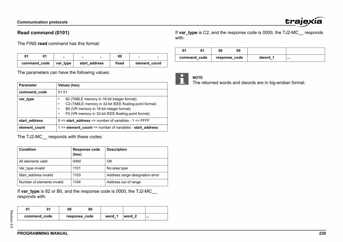
Comm
PROG 239
Revision 5.0
Read
The F/i
The p/i
The T/i
If varrespo/i
ponse code is 0000, the TJ2-MC__ responds
01
com
Param
comm
var_t
start_
elem
Cond
All ele
Var_t
Start_
Numb
0
co
00
_code dword_1 ...
and dwords are in big-endian format.
unication protocols
RAMMING MANUAL
command (0101)
INS read command has this format:
arameters can have the following values:
J2-MC__ responds with these codes:
_type is 82 or B0, and the response code is 0000, the TJ2-MC__ nds with:
If var_type is C2, and the reswith:/i
01 .. .. .. 00 .. ..
mand_code var_type start_address fixed element_count
eter Values (hex)
and_code 01 01
ype • 82 (TABLE memory in 16-bit integer format)• C2 (TABLE memory in 32-bit IEEE floating-point format)• B0 (VR memory in 16-bit integer format)• F0 (VR memory in 32-bit IEEE floating-point format)
address 0 <= start_address <= number of variables - 1 <= FFFF
ent_count 1 <= element_count <= number of variables - start_address
ition Response code (hex)
Description
ments valid 0000 OK
ype invalid 1101 No area type
address invalid 1103 Address range designation error
er of elements invalid 1104 Address out of range
1 01 00 00
mmand_code response_code word_1 word_2 ...
01 01 00
command_code response
NOTEThe returned words
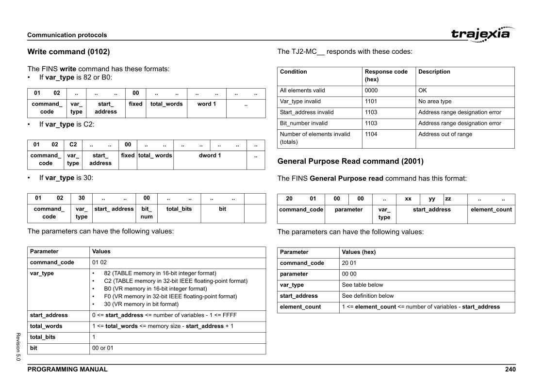
Comm
PROG 240
Revision 5.0
Write
The F• If
/i
• If/i
• If/i
The p/i
these codes:
ommand (2001)
read command has this format:
following values:
01
comc
01
commco
01
comc
Param
comm
var_t
start_
total_
total_
bit
esponse code hex)
Description
000 OK
101 No area type
103 Address range designation error
103 Address range designation error
104 Address out of range
.. xx yy zz .. ..
var_type
start_address element_count
ex)
below
tion below
ent_count <= number of variables - start_address
unication protocols
RAMMING MANUAL
command (0102)
INS write command has these formats: var_type is 82 or B0:
var_type is C2:
var_type is 30:
arameters can have the following values:
The TJ2-MC__ responds with/i
General Purpose Read c
The FINS General Purpose /i
The parameters can have the/i
/i
02 .. .. .. 00 .. .. .. .. .. ..
mand_ode
var_ type
start_ address
fixed total_words word 1 ..
02 C2 .. .. 00 .. .. .. .. .. .. ..
and_de
var_type
start_ address
fixed total_ words dword 1 ..
02 30 .. .. 00 .. .. .. ..
mand_ ode
var_ type
start_ address bit_ num
total_bits bit
eter Values
and_code 01 02
ype • 82 (TABLE memory in 16-bit integer format)• C2 (TABLE memory in 32-bit IEEE floating-point format)• B0 (VR memory in 16-bit integer format)• F0 (VR memory in 32-bit IEEE floating-point format)• 30 (VR memory in bit format)
address 0 <= start_address <= number of variables - 1 <= FFFF
words 1 <= total_words <= memory size - start_address + 1
bits 1
00 or 01
Condition R(
All elements valid 0
Var_type invalid 1
Start_address invalid 1
Bit_number invalid 1
Number of elements invalid (totals)
1
20 01 00 00
command_code parameter
Parameter Values (h
command_code 20 01
parameter 00 00
var_type See table
start_address See defini
element_count 1 <= elem
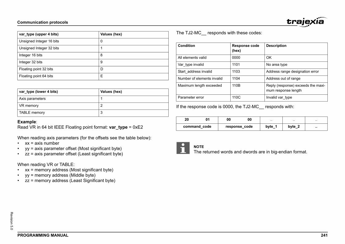
Comm
PROG 241
Revision 5.0
/i
ExamRead
When• xx• yy• zz
When• xx• yy• zz
these codes:
the TJ2-MC__ responds with:
var_t
Unsig
Unsig
Intege
Intege
Floati
Floati
var_t
Axis p
VR m
TABL
esponse code hex)
Description
000 OK
101 No area type
103 Address range designation error
104 Address out of range
10B Reply (response) exceeds the maxi-mum response length
10C Invalid var_type
00 .. .. ..
onse_code byte_1 byte_2 ..
and dwords are in big-endian format.
unication protocols
RAMMING MANUAL
ple: VR in 64 bit IEEE Floating point format: var_type = 0xE2
reading axis parameters (for the offsets see the table below): = axis number = axis parameter offset (Most significant byte) = axis parameter offset (Least significant byte)
reading VR or TABLE: = memory address (Most significant byte) = memory address (Middle byte) = memory address (Least Significant byte)
The TJ2-MC__ responds with/i
If the response code is 0000,/i
/i
ype (upper 4 bits) Values (hex)
ned Integer 16 bits 0
ned Integer 32 bits 1
r 16 bits 8
r 32 bits 9
ng point 32 bits D
ng point 64 bits E
ype (lower 4 bits) Values (hex)
arameters 1
emory 2
E memory 3
Condition R(
All elements valid 0
Var_type invalid 1
Start_address invalid 1
Number of elements invalid 1
Maximum length exceeded 1
Parameter error 1
20 01 00
command_code resp
NOTEThe returned words
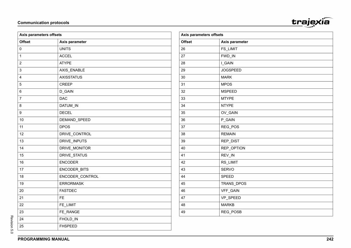
Comm
PROG 242
Revision 5.0
Axis
Offse
0
1
2
3
4
5
6
7
8
9
10
11
12
13
14
15
16
17
18
19
20
21
22
23
24
25
D
T
ION
POS
D
B
meter
unication protocols
RAMMING MANUAL
parameters offsets
t Axis parameter
UNITS
ACCEL
ATYPE
AXIS_ENABLE
AXISSTATUS
CREEP
D_GAIN
DAC
DATUM_IN
DECEL
DEMAND_SPEED
DPOS
DRIVE_CONTROL
DRIVE_INPUTS
DRIVE_MONITOR
DRIVE_STATUS
ENCODER
ENCODER_BITS
ENCODER_CONTROL
ERRORMASK
FASTDEC
FE
FE_LIMIT
FE_RANGE
FHOLD_IN
FHSPEED
26 FS_LIMIT
27 FWD_IN
28 I_GAIN
29 JOGSPEE
30 MARK
31 MPOS
32 MSPEED
33 MTYPE
34 NTYPE
35 OV_GAIN
36 P_GAIN
37 REG_POS
38 REMAIN
39 REP_DIS
40 REP_OPT
41 REV_IN
42 RS_LIMIT
43 SERVO
44 SPEED
45 TRANS_D
46 VFF_GAIN
47 VP_SPEE
48 MARKB
49 REG_POS
Axis parameters offsets
Offset Axis para
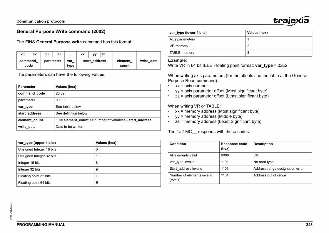
Comm
PROG 243
Revision 5.0
Gene
The F/i
The p/i
/i
/i
ing point format: var_type = 0xE2
s (for the offsets see the table at the General
t (Most significant byte)t (Least significant byte)
ost significant byte)iddle byte)ast Significant byte)
these codes:
20
comc
Param
comm
param
var_t
start_
elem
write
var_t
Unsig
Unsig
Intege
Intege
Floati
Floati
Values (hex)
1
2
3
esponse code hex)
Description
000 OK
101 No area type
103 Address range designation error
104 Address out of range
unication protocols
RAMMING MANUAL
ral Purpose Write command (2002)
INS General Purpose write command has this format:
arameters can have the following values:
Example:Write VR in 64 bit IEEE Float
When writing axis parameterPurpose Read command):• xx = axis number• yy = axis parameter offse• zz = axis parameter offse
When writing VR or TABLE:• xx = memory address (M• yy = memory address (M• zz = memory address (Le
The TJ2-MC__ responds with/i
02 00 00 .. xx yy zz .. .. .. ..
mand_ode
parameter var_type
start_address element_count
write_data
eter Values (hex)
and_code 20 02
eter 00 00
ype See table below
address See definition below
ent_count 1 <= element_count <= number of variables - start_address
_data Data to be written
ype (upper 4 bits) Values (hex)
ned Integer 16 bits 0
ned Integer 32 bits 1
r 16 bits 8
r 32 bits 9
ng point 32 bits D
ng point 64 bits E
var_type (lower 4 bits)
Axis parameters
VR memory
TABLE memory
Condition R(
All elements valid 0
Var_type invalid 1
Start_address invalid 1
Number of elements invalid (totals)
1
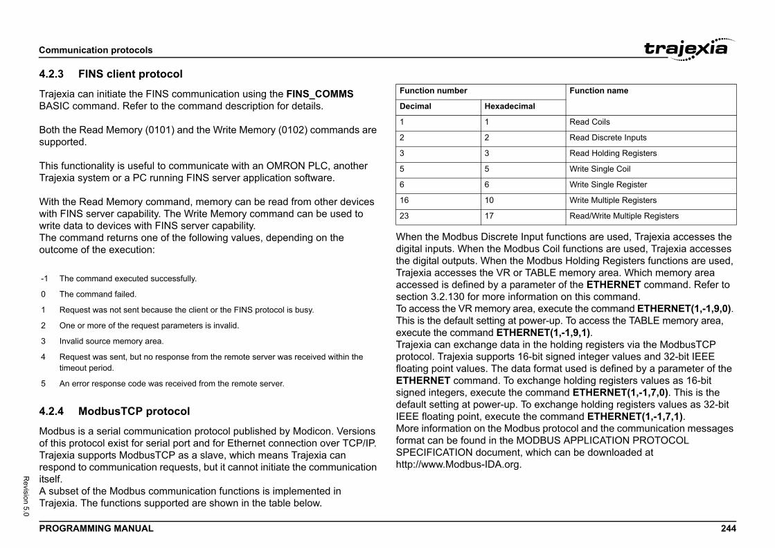
Comm
PROG 244
Revision 5.0
4.2.3
TrajeBASI
Both suppo
This fTraje
With with Fwrite The coutco/i
4.2.4
Modbof thisTrajerespoitself.A subTraje
nput functions are used, Trajexia accesses the bus Coil functions are used, Trajexia accesses Modbus Holding Registers functions are used, TABLE memory area. Which memory area ameter of the ETHERNET command. Refer to rmation on this command.a, execute the command ETHERNET(1,-1,9,0).
ower-up. To access the TABLE memory area, NET(1,-1,9,1).
n the holding registers via the ModbusTCP -bit signed integer values and 32-bit IEEE
a format used is defined by a parameter of the change holding registers values as 16-bit command ETHERNET(1,-1,7,0). This is the o exchange holding registers values as 32-bit he command ETHERNET(1,-1,7,1).bus protocol and the communication messages ODBUS APPLICATION PROTOCOL which can be downloaded at
-1 T
0 T
1 R
2 O
3 I
4 Rt
5 A
Function name
al
Read Coils
Read Discrete Inputs
Read Holding Registers
Write Single Coil
Write Single Register
Write Multiple Registers
Read/Write Multiple Registers
unication protocols
RAMMING MANUAL
FINS client protocol
xia can initiate the FINS communication using the FINS_COMMS C command. Refer to the command description for details.
the Read Memory (0101) and the Write Memory (0102) commands are rted.
unctionality is useful to communicate with an OMRON PLC, another xia system or a PC running FINS server application software.
the Read Memory command, memory can be read from other devices INS server capability. The Write Memory command can be used to
data to devices with FINS server capability.ommand returns one of the following values, depending on the me of the execution:
ModbusTCP protocol
us is a serial communication protocol published by Modicon. Versions protocol exist for serial port and for Ethernet connection over TCP/IP.
xia supports ModbusTCP as a slave, which means Trajexia can nd to communication requests, but it cannot initiate the communication
set of the Modbus communication functions is implemented in xia. The functions supported are shown in the table below.
/i
When the Modbus Discrete Idigital inputs. When the Modthe digital outputs. When theTrajexia accesses the VR or accessed is defined by a parsection 3.2.130 for more infoTo access the VR memory areThis is the default setting at pexecute the command ETHERTrajexia can exchange data iprotocol. Trajexia supports 16floating point values. The datETHERNET command. To exsigned integers, execute the default setting at power-up. TIEEE floating point, execute tMore information on the Modformat can be found in the MSPECIFICATION document, http://www.Modbus-IDA.org.
he command executed successfully.
he command failed.
equest was not sent because the client or the FINS protocol is busy.
ne or more of the request parameters is invalid.
nvalid source memory area.
equest was sent, but no response from the remote server was received within the imeout period.
n error response code was received from the remote server.
Function number
Decimal Hexadecim
1 1
2 2
3 3
5 5
6 6
16 10
23 17
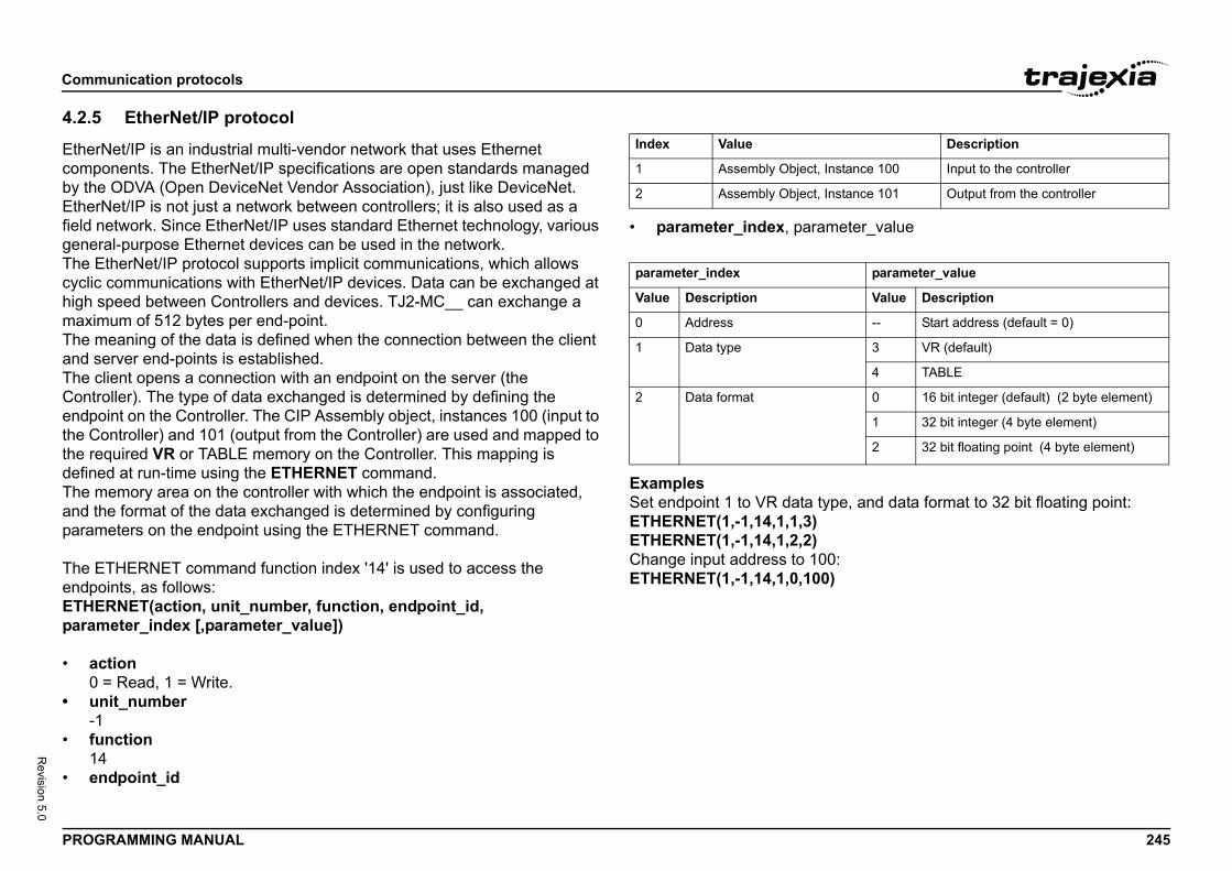
Comm
PROG 245
Revision 5.0
4.2.5
Ethercompby theEtherfield ngenerThe Ecyclichigh smaximThe mand sThe cContrendpothe Cthe redefineThe mand thparam
The EendpoETHEparam
• a0
• u-1
• fu1
• e
eter_value
e, and data format to 32 bit floating point:
:
Description
stance 100 Input to the controller
stance 101 Output from the controller
parameter_value
Value Description
-- Start address (default = 0)
3 VR (default)
4 TABLE
0 16 bit integer (default) (2 byte element)
1 32 bit integer (4 byte element)
2 32 bit floating point (4 byte element)
unication protocols
RAMMING MANUAL
EtherNet/IP protocol
Net/IP is an industrial multi-vendor network that uses Ethernet onents. The EtherNet/IP specifications are open standards managed ODVA (Open DeviceNet Vendor Association), just like DeviceNet.
Net/IP is not just a network between controllers; it is also used as a etwork. Since EtherNet/IP uses standard Ethernet technology, various al-purpose Ethernet devices can be used in the network.therNet/IP protocol supports implicit communications, which allows communications with EtherNet/IP devices. Data can be exchanged at peed between Controllers and devices. TJ2-MC__ can exchange a um of 512 bytes per end-point.eaning of the data is defined when the connection between the client
erver end-points is established.lient opens a connection with an endpoint on the server (the oller). The type of data exchanged is determined by defining the int on the Controller. The CIP Assembly object, instances 100 (input to
ontroller) and 101 (output from the Controller) are used and mapped to quired VR or TABLE memory on the Controller. This mapping is d at run-time using the ETHERNET command.emory area on the controller with which the endpoint is associated, e format of the data exchanged is determined by configuring eters on the endpoint using the ETHERNET command.
THERNET command function index '14' is used to access the ints, as follows:RNET(action, unit_number, function, endpoint_id, eter_index [,parameter_value])
ction = Read, 1 = Write.nit_number
nction4ndpoint_id
/i
• parameter_index, param/i
ExamplesSet endpoint 1 to VR data typETHERNET(1,-1,14,1,1,3)ETHERNET(1,-1,14,1,2,2)Change input address to 100ETHERNET(1,-1,14,1,0,100)
Index Value
1 Assembly Object, In
2 Assembly Object, In
parameter_index
Value Description
0 Address
1 Data type
2 Data format
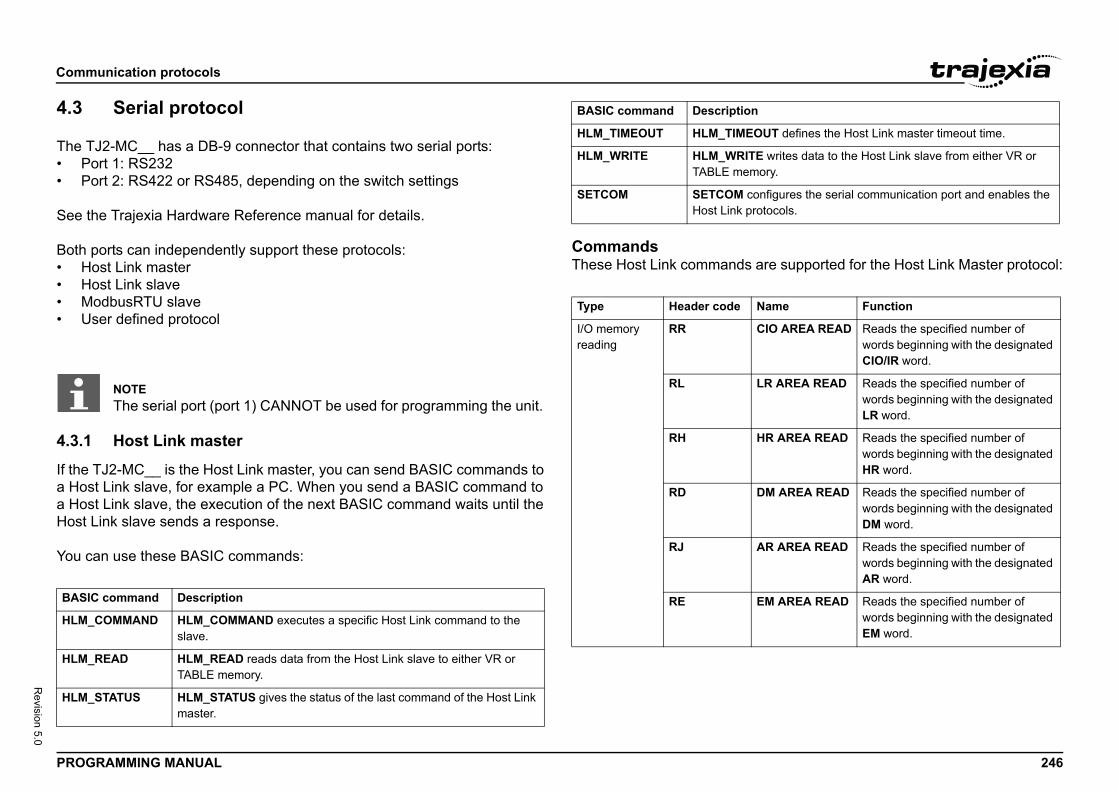
Comm
PROG 246
Revision 5.0
4.3
The T• P• P
See t
Both • H• H• M• U
4.3.1
If the a Hosa HosHost
You c/i
are supported for the Host Link Master protocol:
BASI
HLM_
HLM_
HLM_
UT defines the Host Link master timeout time.
E writes data to the Host Link slave from either VR or ory.
nfigures the serial communication port and enables the otocols.
Name Function
CIO AREA READ Reads the specified number of words beginning with the designated CIO/IR word.
LR AREA READ Reads the specified number of words beginning with the designated LR word.
HR AREA READ Reads the specified number of words beginning with the designated HR word.
DM AREA READ Reads the specified number of words beginning with the designated DM word.
AR AREA READ Reads the specified number of words beginning with the designated AR word.
EM AREA READ Reads the specified number of words beginning with the designated EM word.
unication protocols
RAMMING MANUAL
Serial protocol
J2-MC__ has a DB-9 connector that contains two serial ports:ort 1: RS232ort 2: RS422 or RS485, depending on the switch settings
he Trajexia Hardware Reference manual for details.
ports can independently support these protocols:ost Link masterost Link slaveodbusRTU slaveser defined protocol
Host Link master
TJ2-MC__ is the Host Link master, you can send BASIC commands to t Link slave, for example a PC. When you send a BASIC command to t Link slave, the execution of the next BASIC command waits until the
Link slave sends a response.
an use these BASIC commands:
CommandsThese Host Link commands /i
NOTEThe serial port (port 1) CANNOT be used for programming the unit.
C command Description
COMMAND HLM_COMMAND executes a specific Host Link command to the slave.
READ HLM_READ reads data from the Host Link slave to either VR or TABLE memory.
STATUS HLM_STATUS gives the status of the last command of the Host Link master.
HLM_TIMEOUT HLM_TIMEO
HLM_WRITE HLM_WRITTABLE mem
SETCOM SETCOM coHost Link pr
Type Header code
I/O memoryreading
RR
RL
RH
RD
RJ
RE
BASIC command Description
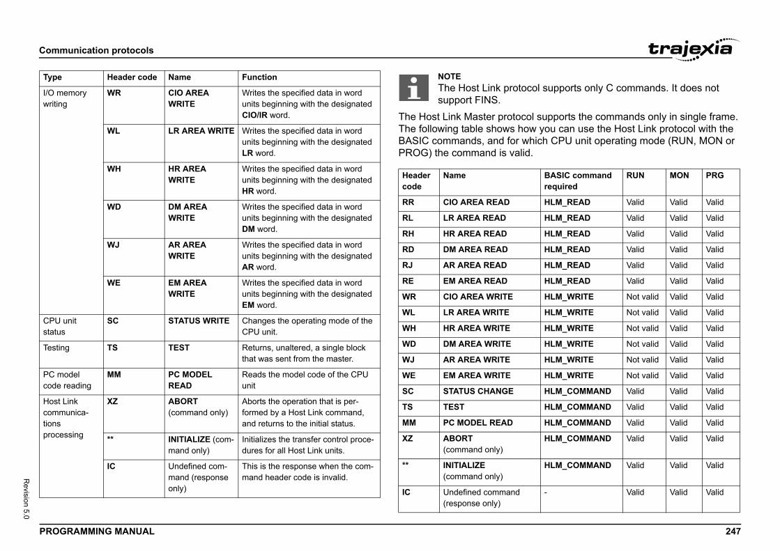
Comm
PROG 247
Revision 5.0
l supports the commands only in single frame. w you can use the Host Link protocol with the hich CPU unit operating mode (RUN, MON or .
I/O mwritin
CPU status
Testin
PC mcode
Host commtionsproce
Typecol supports only C commands. It does not
BASIC command required
RUN MON PRG
HLM_READ Valid Valid Valid
HLM_READ Valid Valid Valid
HLM_READ Valid Valid Valid
HLM_READ Valid Valid Valid
HLM_READ Valid Valid Valid
HLM_READ Valid Valid Valid
HLM_WRITE Not valid Valid Valid
HLM_WRITE Not valid Valid Valid
HLM_WRITE Not valid Valid Valid
HLM_WRITE Not valid Valid Valid
HLM_WRITE Not valid Valid Valid
HLM_WRITE Not valid Valid Valid
HLM_COMMAND Valid Valid Valid
HLM_COMMAND Valid Valid Valid
HLM_COMMAND Valid Valid Valid
HLM_COMMAND Valid Valid Valid
HLM_COMMAND Valid Valid Valid
- Valid Valid Valid
unication protocols
RAMMING MANUAL
The Host Link Master protocoThe following table shows hoBASIC commands, and for wPROG) the command is valid/i
emoryg
WR CIO AREA WRITE
Writes the specified data in word units beginning with the designated CIO/IR word.
WL LR AREA WRITE Writes the specified data in word units beginning with the designated LR word.
WH HR AREA WRITE
Writes the specified data in word units beginning with the designated HR word.
WD DM AREA WRITE
Writes the specified data in word units beginning with the designated DM word.
WJ AR AREA WRITE
Writes the specified data in word units beginning with the designated AR word.
WE EM AREA WRITE
Writes the specified data in word units beginning with the designated EM word.
unit SC STATUS WRITE Changes the operating mode of the CPU unit.
g TS TEST Returns, unaltered, a single block that was sent from the master.
odelreading
MM PC MODEL READ
Reads the model code of the CPU unit
Linkunica-
ssing
XZ ABORT(command only)
Aborts the operation that is per-formed by a Host Link command, and returns to the initial status.
** INITIALIZE (com-mand only)
Initializes the transfer control proce-dures for all Host Link units.
IC Undefined com-mand (response only)
This is the response when the com-mand header code is invalid.
Header code Name Function NOTEThe Host Link protosupport FINS.
Headercode
Name
RR CIO AREA READ
RL LR AREA READ
RH HR AREA READ
RD DM AREA READ
RJ AR AREA READ
RE EM AREA READ
WR CIO AREA WRITE
WL LR AREA WRITE
WH HR AREA WRITE
WD DM AREA WRITE
WJ AR AREA WRITE
WE EM AREA WRITE
SC STATUS CHANGE
TS TEST
MM PC MODEL READ
XZ ABORT(command only)
** INITIALIZE(command only)
IC Undefined command(response only)
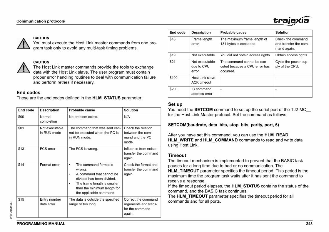
Comm
PROG 248
Revision 5.0
End These/i
mand to set up the serial port of the TJ2-MC__ ocol. Set the command as follows:
its, stop_bits, parity, port, 6)
and, you can use the HLM_READ, MAND commands to read and write data
plemented to prevent that the BASIC task bad or no communication. The pecifies the timeout period. This period is the ask waits after it has sent the command to
the HLM_STATUS contains the status of the sk continues.ter specifies the timeout period for all
End c
$00
$01
$13
$14
$15
he maximum frame length of 31 bytes is exceeded.
Check the command and transfer the com-mand again.
ou did not obtain access rights. Obtain access rights.
he command cannot be exe-uted because a CPU error has ccurred.
Cycle the power sup-ply of the CPU.
-
-
robable cause Solution
unication protocols
RAMMING MANUAL
codes are the end codes defined in the HLM_STATUS parameter:
Set upYou need the SETCOM comfor the Host Link Master prot
SETCOM(baudrate, data_b
After you have set this commHLM_WRITE and HLM_COMusing Host Link.
TimeoutThe timeout mechanism is impauses for a long time due toHLM_TIMEOUT parameter smaximum time the program treceive a response.If the timeout period elapses,command, and the BASIC taThe HLM_TIMEOUT paramecommands and for all ports.
CAUTIONYou must execute the Host Link master commands from one pro-gram task only to avoid any multi-task timing problems.
CAUTIONThe Host Link master commands provide the tools to exchange data with the Host Link slave. The user program must contain proper error handling routines to deal with communication failure and perform retries if necessary.
ode Description Probable cause Solution
Normalcompletion
No problem exists. N/A
Not executable in RUN mode
The command that was sent can-not be executed when the PC is in RUN mode.
Check the relation between the com-mand and the PC mode.
FCS error The FCS is wrong. Influence from noise, transfer the command again.
Format error • The command format is wrong.
• A command that cannot be divided has been divided.
• The frame length is smaller than the minimum length for the applicable command.
Check the format and transfer the command again.
Entry number data error
The data is outside the specified range or too long.
Correct the command arguments and trans-fer the command again.
$18 Frame length error
T1
$19 Not executable Y
$21 Not executable due to CPU error.
Tco
$100 Host Link slave ACK timeout
-
$200 IC command address error
-
End code Description P
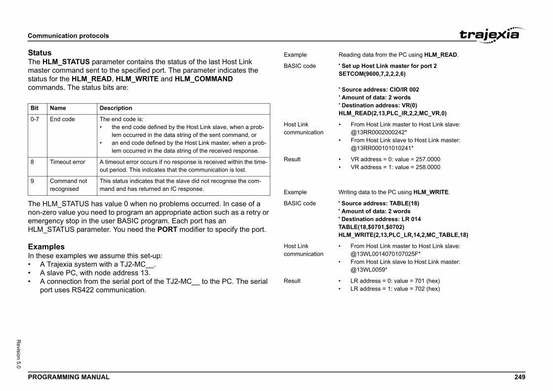
Comm
PROG 249
Revision 5.0
StatuThe Hmastestatuscomm/i
The Hnon-zemerHLM_
ExamIn the• A• A• A
p
/i
Bit
0-7
8
9
from the PC using HLM_READ.
Link master for port 20,7,2,2,2,6)
ress: CIO/IR 002ata: 2 words
address: VR(0)2,13,PLC_IR,2,2,MC_VR,0)
st Link master to Host Link slave:002000242*st Link slave to Host Link master:00101010241*
ss = 0: value = 257.0000ss = 1: value = 258.0000
the PC using HLM_WRITE.
ress: TABLE(18)ata: 2 words
address: LR 014701,$0702)(2,13,PLC_LR,14,2,MC_TABLE,18)
st Link master to Host Link slave:014070107025F*
st Link slave to Host Link master:059*
ss = 0: value = 701 (hex)ss = 1: value = 702 (hex)
unication protocols
RAMMING MANUAL
sLM_STATUS parameter contains the status of the last Host Link r command sent to the specified port. The parameter indicates the for the HLM_READ, HLM_WRITE and HLM_COMMAND ands. The status bits are:
LM_STATUS has value 0 when no problems occurred. In case of a ero value you need to program an appropriate action such as a retry or gency stop in the user BASIC program. Each port has an STATUS parameter. You need the PORT modifier to specify the port.
plesse examples we assume this set-up: Trajexia system with a TJ2-MC__. slave PC, with node address 13. connection from the serial port of the TJ2-MC__ to the PC. The serial ort uses RS422 communication.
/i
/i
Name Description
End code The end code is:• the end code defined by the Host Link slave, when a prob-
lem occurred in the data string of the sent command, or• an end code defined by the Host Link master, when a prob-
lem occurred in the data string of the received response.
Timeout error A timeout error occurs if no response is received within the time-out period. This indicates that the communication is lost.
Command not recognised
This status indicates that the slave did not recognise the com-mand and has returned an IC response.
Example Reading data
BASIC code ' Set up HostSETCOM(960
' Source add' Amount of d' DestinationHLM_READ(
Host Linkcommunication
• From Ho@13RR0
• From Ho@13RR0
Result • VR addre• VR addre
Example Writing data to
BASIC code ' Source add' Amount of d' DestinationTABLE(18,$0HLM_WRITE
Host Linkcommunication
• From Ho@13WL0
• From Ho@13WL0
Result • LR addre• LR addre
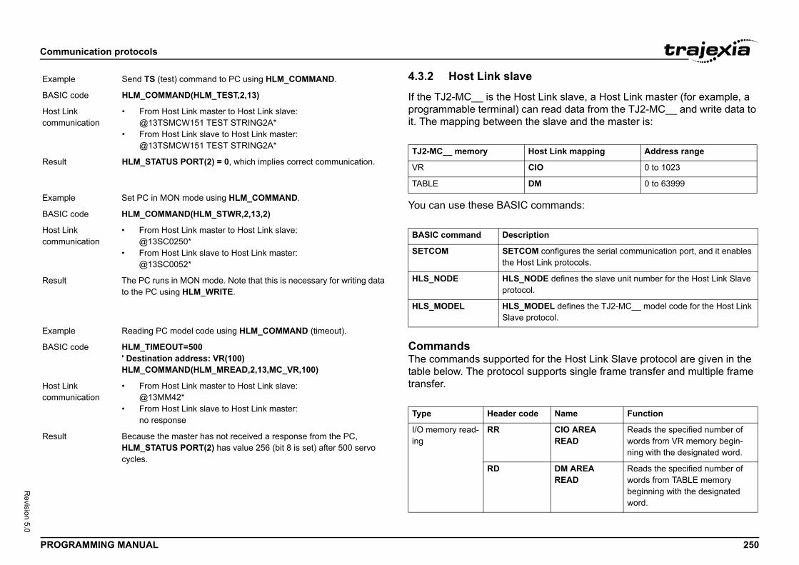
Comm
PROG 250
Revision 5.0
/i
/i
ink slave, a Host Link master (for example, a read data from the TJ2-MC__ and write data to slave and the master is:
mmands:
r the Host Link Slave protocol are given in the ports single frame transfer and multiple frame
Exam
BASIC
Host Lcomm
Resul
Exam
BASIC
Host Lcomm
Resul
Exam
BASIC
Host Lcomm
Resul
st Link mapping Address range
0 to 1023
0 to 63999
n
configures the serial communication port, and it enables ink protocols.
E defines the slave unit number for the Host Link Slave
EL defines the TJ2-MC__ model code for the Host Link ocol.
Name Function
CIO AREA READ
Reads the specified number of words from VR memory begin-ning with the designated word.
DM AREA READ
Reads the specified number of words from TABLE memory beginning with the designated word.
unication protocols
RAMMING MANUAL
4.3.2 Host Link slave
If the TJ2-MC__ is the Host Lprogrammable terminal) can it. The mapping between the/i
You can use these BASIC co/i
CommandsThe commands supported fotable below. The protocol suptransfer./i
ple Send TS (test) command to PC using HLM_COMMAND.
code HLM_COMMAND(HLM_TEST,2,13)
inkunication
• From Host Link master to Host Link slave:@13TSMCW151 TEST STRING2A*
• From Host Link slave to Host Link master:@13TSMCW151 TEST STRING2A*
t HLM_STATUS PORT(2) = 0, which implies correct communication.
ple Set PC in MON mode using HLM_COMMAND.
code HLM_COMMAND(HLM_STWR,2,13,2)
inkunication
• From Host Link master to Host Link slave:@13SC0250*
• From Host Link slave to Host Link master:@13SC0052*
t The PC runs in MON mode. Note that this is necessary for writing data to the PC using HLM_WRITE.
ple Reading PC model code using HLM_COMMAND (timeout).
code HLM_TIMEOUT=500' Destination address: VR(100)HLM_COMMAND(HLM_MREAD,2,13,MC_VR,100)
inkunication
• From Host Link master to Host Link slave:@13MM42*
• From Host Link slave to Host Link master:no response
t Because the master has not received a response from the PC, HLM_STATUS PORT(2) has value 256 (bit 8 is set) after 500 servo cycles.
TJ2-MC__ memory Ho
VR CIO
TABLE DM
BASIC command Descriptio
SETCOM SETCOM the Host L
HLS_NODE HLS_NODprotocol.
HLS_MODEL HLS_MODSlave prot
Type Header code
I/O memory read-ing
RR
RD
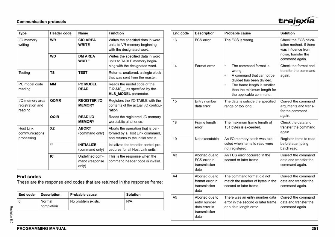
Comm
PROG 251
Revision 5.0
End These/i
I/O mwritin
Testin
PC mreadin
I/O mregistreadin
Host commproce
End c
0
Type
he FCS is wrong. Check the FCS calcu-lation method. If there was influence from noise, transfer the command again.
The command format is wrong.A command that cannot be divided has been divided.The frame length is smaller than the minimum length for the applicable command.
Check the format and transfer the command again.
he data is outside the specified nge or too long.
Correct the command arguments and trans-fer the command again.
he maximum frame length of 31 bytes is exceeded.
Check the data and transfer the command again.
n I/O memory batch was exe-uted when items to read were ot registered.
Register items to read before attempting batch read.
n FCS error occurred in the econd or later frame.
Correct the command data and transfer the command again.
he command format did not atch the number of bytes in the
econd or later frame.
Correct the command data and transfer the command again.
here was an entry number data rror in the second or later frame r a data length error.
Correct the command data and transfer the command again.
robable cause Solution
unication protocols
RAMMING MANUAL
codes are the response end codes that are returned in the response frame:
emoryg
WR CIO AREA WRITE
Writes the specified data in word units to VR memory beginning with the designated word.
WD DM AREA WRITE
Writes the specified data in word units to TABLE memory begin-ning with the designated word.
g TS TEST Returns, unaltered, a single block that was sent from the master.
odel code g
MM PC MODEL READ
Reads the model code of the TJ2-MC__ as specified by the HLS_MODEL parameter.
emory area ration and g
QQMR REGISTER I/O MEMORY
Registers the I/O TABLE with the contents of the actual I/O configu-ration
QQIR READ I/O MEMORY
Reads the registered I/O memory words/bits all at once.
Linkunications ssing
XZ ABORT(command only)
Aborts the operation that is per-formed by a Host Link command, and returns to the initial status.
** INITIALIZE(command only)
Initializes the transfer control pro-cedures for all Host Link units.
IC Undefined com-mand (response only)
This is the response when the command header code is invalid.
ode Description Probable cause Solution
Normalcompletion
No problem exists. N/A
Header code Name Function
13 FCS error T
14 Format error •
•
•
15 Entry number data error
Tra
18 Frame length error
T1
19 Not executable Acn
A3 Aborted due to FCS error in transmission data
As
A4 Aborted due to format error in transmission data
Tms
A5 Aborted due to entry number data error in transmission data
Teo
End code Description P
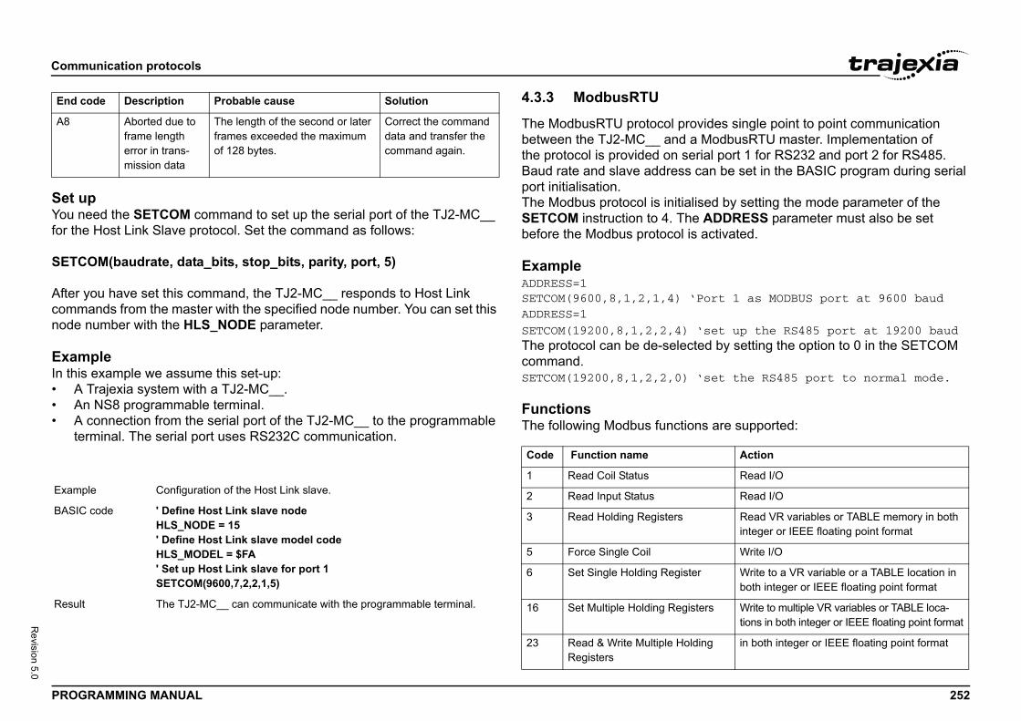
Comm
PROG 252
Revision 5.0
Set uYou nfor th
SETC
After commnode
ExamIn this• A• A• A
te
/i
ovides single point to point communication a ModbusRTU master. Implementation ofrial port 1 for RS232 and port 2 for RS485.
can be set in the BASIC program during serial
lised by setting the mode parameter of the e ADDRESS parameter must also be set s activated.
Port 1 as MODBUS port at 9600 baud
‘set up the RS485 port at 19200 baudted by setting the option to 0 in the SETCOM
‘set the RS485 port to normal mode.
ns are supported:
A8
Exam
BASIC
Resul
End c
Action
Read I/O
Read I/O
Read VR variables or TABLE memory in both integer or IEEE floating point format
Write I/O
er Write to a VR variable or a TABLE location in both integer or IEEE floating point format
sters Write to multiple VR variables or TABLE loca-tions in both integer or IEEE floating point format
lding in both integer or IEEE floating point format
unication protocols
RAMMING MANUAL
peed the SETCOM command to set up the serial port of the TJ2-MC__ e Host Link Slave protocol. Set the command as follows:
OM(baudrate, data_bits, stop_bits, parity, port, 5)
you have set this command, the TJ2-MC__ responds to Host Link ands from the master with the specified node number. You can set this number with the HLS_NODE parameter.
ple example we assume this set-up:
Trajexia system with a TJ2-MC__.n NS8 programmable terminal. connection from the serial port of the TJ2-MC__ to the programmable rminal. The serial port uses RS232C communication.
4.3.3 ModbusRTU
The ModbusRTU protocol prbetween the TJ2-MC__ and the protocol is provided on seBaud rate and slave addressport initialisation.The Modbus protocol is initiaSETCOM instruction to 4. Thbefore the Modbus protocol i
ExampleADDRESS=1SETCOM(9600,8,1,2,1,4) ‘ADDRESS=1
SETCOM(19200,8,1,2,2,4) The protocol can be de-seleccommand.SETCOM(19200,8,1,2,2,0)
FunctionsThe following Modbus functio/i
Aborted due to frame length error in trans-mission data
The length of the second or later frames exceeded the maximum of 128 bytes.
Correct the command data and transfer the command again.
ple Configuration of the Host Link slave.
code ' Define Host Link slave nodeHLS_NODE = 15' Define Host Link slave model codeHLS_MODEL = $FA' Set up Host Link slave for port 1SETCOM(9600,7,2,2,1,5)
t The TJ2-MC__ can communicate with the programmable terminal.
ode Description Probable cause Solution
Code Function name
1 Read Coil Status
2 Read Input Status
3 Read Holding Registers
5 Force Single Coil
6 Set Single Holding Regist
16 Set Multiple Holding Regi
23 Read & Write Multiple HoRegisters
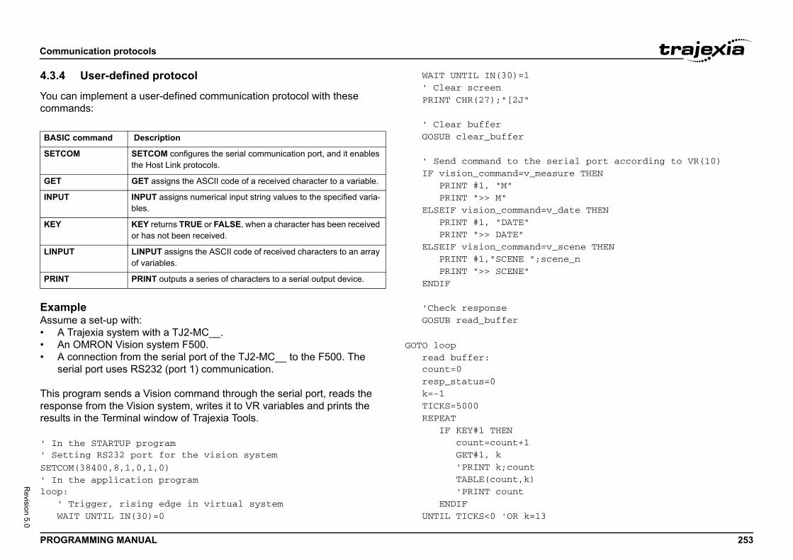
Comm
PROG 253
Revision 5.0
4.3.4
You ccomm/i
ExamAssum• A• A• A
se
This presporesult
' In ' Set
SETCO' In loop: ' WA
serial port according to VR(10)easure THEN
=v_date THEN
=v_scene THENscene_n
3
BASI
SETC
GET
INPU
KEY
LINP
PRIN
unication protocols
RAMMING MANUAL
User-defined protocol
an implement a user-defined communication protocol with these ands:
plee a set-up with:
Trajexia system with a TJ2-MC__.n OMRON Vision system F500. connection from the serial port of the TJ2-MC__ to the F500. The rial port uses RS232 (port 1) communication.
rogram sends a Vision command through the serial port, reads the nse from the Vision system, writes it to VR variables and prints the s in the Terminal window of Trajexia Tools.
the STARTUP programting RS232 port for the vision system
M(38400,8,1,0,1,0)the application program
Trigger, rising edge in virtual systemIT UNTIL IN(30)=0
WAIT UNTIL IN(30)=1 ' Clear screen PRINT CHR(27);"[2J" ' Clear buffer GOSUB clear_buffer ' Send command to the IF vision_command=v_m PRINT #1, "M" PRINT ">> M" ELSEIF vision_command PRINT #1, "DATE" PRINT ">> DATE" ELSEIF vision_command PRINT #1,"SCENE "; PRINT ">> SCENE" ENDIF 'Check response GOSUB read_buffer
GOTO loop read buffer: count=0 resp_status=0 k=-1 TICKS=5000 REPEAT IF KEY#1 THEN count=count+1 GET#1, k 'PRINT k;count TABLE(count,k) 'PRINT count ENDIF UNTIL TICKS<0 'OR k=1
C command Description
OM SETCOM configures the serial communication port, and it enables the Host Link protocols.
GET assigns the ASCII code of a received character to a variable.
T INPUT assigns numerical input string values to the specified varia-bles.
KEY returns TRUE or FALSE, when a character has been received or has not been received.
UT LINPUT assigns the ASCII code of received characters to an array of variables.
T PRINT outputs a series of characters to a serial output device.
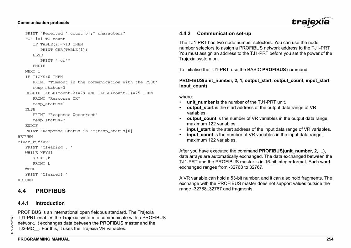
Comm
PROG 254
Revision 5.0
PR FO NE IF EL EL EN PR
RETURclear PR WH WE PR
RETUR
4.4
4.4.1
PROFTJ1-PnetwoTJ2-M
et-up
umber selectors. You can use the node PROFIBUS network address to the TJ1-PRT. to the TJ1-PRT before you set the power of the
the BASIC PROFIBUS command:
, 1, output_start, output_count, input_start,
ber of the TJ1-PRT unit.address of the output data range of VR
ber of VR variables in the output data range,
dress of the input data range of VR variables.er of VR variables in the input data range,
command PROFIBUS(unit_number, 2, ...), exchanged. The data exchanged between the master is in 16-bit integer format. Each word 68 to 32767.
bit number, and it can also hold fragments. The S master does not support values outside the gments.
unication protocols
RAMMING MANUAL
INT "Received ";count[0];" characters"R i=1 TO count IF TABLE(i)<>13 THEN PRINT CHR(TABLE(i)) ELSE PRINT "'cr'" ENDIFXT i TICKS<0 THEN PRINT "Timeout in the communication with the F500" resp_status=3SEIF TABLE(count-2)=79 AND TABLE(count-1)=75 THEN PRINT "Response OK" resp_status=1SE PRINT "Response Uncorrect" resp_status=2DIFINT "Response Status is :";resp_status[0]
N_buffer:INT "Clearing..."ILE KEY#1 GET#1,k PRINT kNDINT "Cleared!!"
N
PROFIBUS
Introduction
IBUS is an international open fieldbus standard. The Trajexia RT enables the Trajexia system to communicate with a PROFIBUS rk. It exchanges data between the PROFIBUS master and the C__. For this, it uses the Trajexia VR variables.
4.4.2 Communication s
The TJ1-PRT has two node nnumber selectors to assign aYou must assign an address Trajexia system on.
To initialise the TJ1-PRT, use
PROFIBUS(unit_number, 2input_count)
where:• unit_number is the num• output_start is the start
variables.• output_count is the num
maximum 122 variables.• input_start is the start ad• input_count is the numb
maximum 122 variables.
After you have executed the data arrays are automaticallyTJ1-PRT and the PROFIBUSexchanged ranges from -327
A VR variable can hold a 53-exchange with the PROFIBUrange -32768..32767 and fra
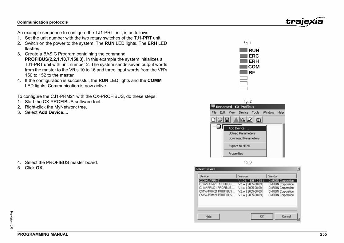
Comm
PROG 255
Revision 5.0
An ex1. S
fig. 1 2. Sfla
3. CPTfr1
4. IfL
To cofig. 21. S
2. R3. S
fig. 34. S5. C
RUNERCERHCOMBF
unication protocols
RAMMING MANUAL
ample sequence to configure the TJ1-PRT unit, is as follows:et the unit number with the two rotary switches of the TJ1-PRT unit.witch on the power to the system. The RUN LED lights. The ERH LED shes.
reate a BASIC Program containing the command ROFIBUS(2,2,1,10,7,150,3). In this example the system initializes a J1-PRT unit with unit number 2. The system sends seven output words om the master to the VR’s 10 to 16 and three input words from the VR’s 50 to 152 to the master. the configuration is successful, the RUN LED lights and the COMM ED lights. Communication is now active.
nfigure the CJ1-PRM21 with the CX-PROFIBUS, do these steps:tart the CX-PROFIBUS software tool.ight-click the MyNetwork tree.elect Add Device....
elect the PROFIBUS master board.lick OK.
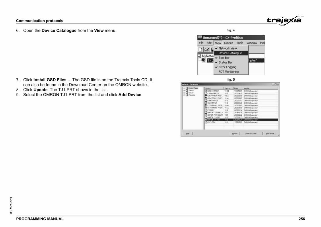
Comm
PROG 256
Revision 5.0
fig. 46. O
fig. 57. Cca
8. C9. S
unication protocols
RAMMING MANUAL
pen the Device Catalogue from the View menu.
lick Install GSD Files.... The GSD file is on the Trajexia Tools CD. It n also be found in the Download Center on the OMRON website.
lick Update. The TJ1-PRT shows in the list.elect the OMRON TJ1-PRT from the list and click Add Device.
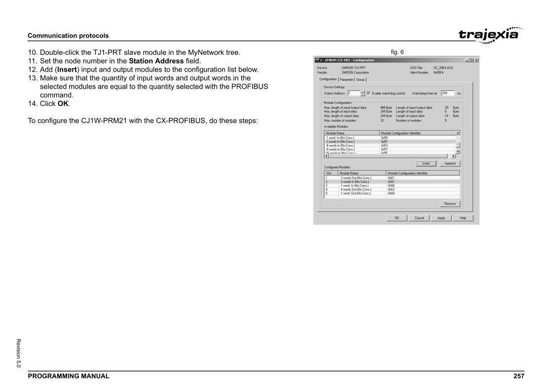
Comm
PROG 257
Revision 5.0
fig. 610. D11. S12. A13. M
seco
14. C
To co
unication protocols
RAMMING MANUAL
ouble-click the TJ1-PRT slave module in the MyNetwork tree.et the node number in the Station Address field.dd (Insert) input and output modules to the configuration list below.ake sure that the quantity of input words and output words in the lected modules are equal to the quantity selected with the PROFIBUS mmand.
lick OK.
nfigure the CJ1W-PRM21 with the CX-PROFIBUS, do these steps:
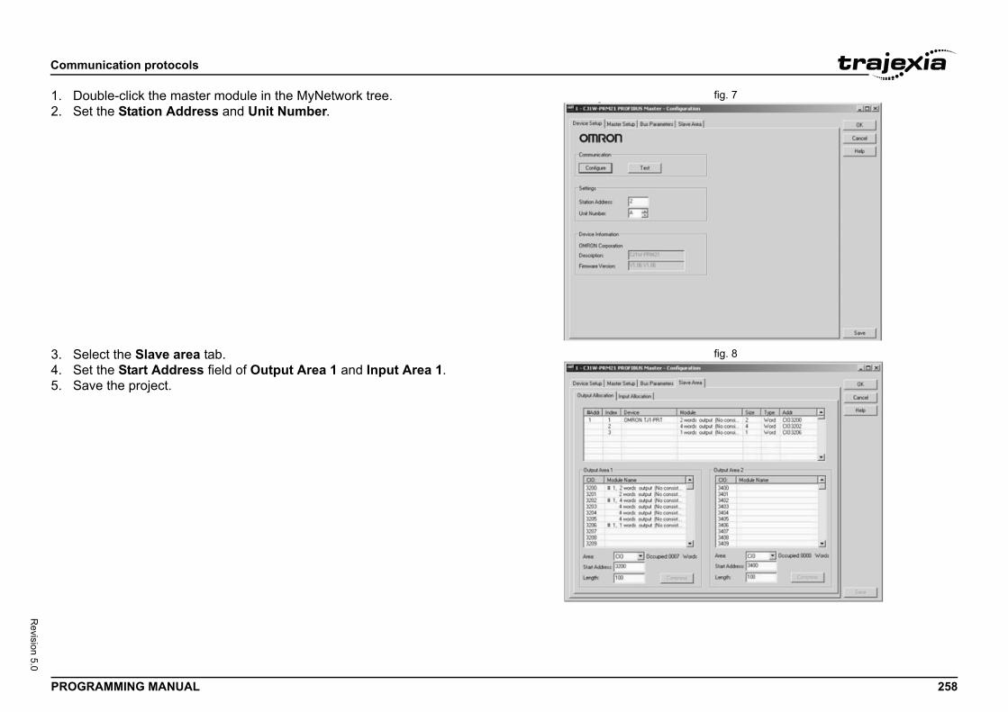
Comm
PROG 258
Revision 5.0
fig. 71. D2. S
fig. 83. S4. S5. S
unication protocols
RAMMING MANUAL
ouble-click the master module in the MyNetwork tree.et the Station Address and Unit Number.
elect the Slave area tab.et the Start Address field of Output Area 1 and Input Area 1.ave the project.
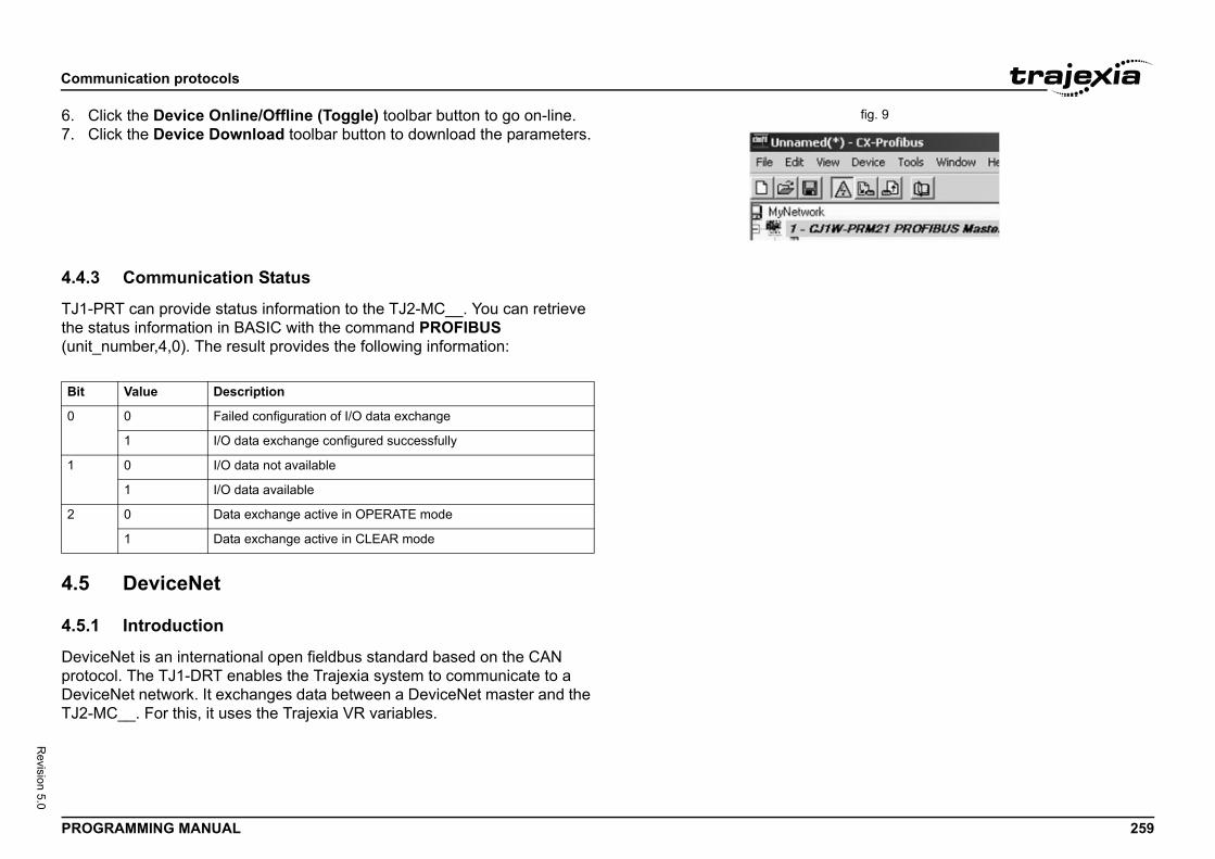
Comm
PROG 259
Revision 5.0
fig. 96. C7. C
4.4.3
TJ1-Pthe st(unit_/i
4.5
4.5.1
DevicprotoDevicTJ2-M
Bit
0
1
2
unication protocols
RAMMING MANUAL
lick the Device Online/Offline (Toggle) toolbar button to go on-line.lick the Device Download toolbar button to download the parameters.
Communication Status
RT can provide status information to the TJ2-MC__. You can retrieve atus information in BASIC with the command PROFIBUS number,4,0). The result provides the following information:
DeviceNet
Introduction
eNet is an international open fieldbus standard based on the CAN col. The TJ1-DRT enables the Trajexia system to communicate to a eNet network. It exchanges data between a DeviceNet master and the C__. For this, it uses the Trajexia VR variables.
Value Description
0 Failed configuration of I/O data exchange
1 I/O data exchange configured successfully
0 I/O data not available
1 I/O data available
0 Data exchange active in OPERATE mode
1 Data exchange active in CLEAR mode
Comm
PROG 260
Revision 5.0
4.5.2
The Tnumb
The Dnumbselecsoftw
To ini
DEVIinput
where• u• o
va• o
m• in• in
m
After data aTJ1-Dexcha
unication protocols
RAMMING MANUAL
Communication set-up
J1-DRT has two node number selectors. You can use the node er selectors to assign a node number to the TJ1-DRT.
eviceNet node numbers range from 0 to 63. If you select a node er with the node number selectors that exceeds this range, you will t the node number that is set by software. The nodes that enable are setting are 64 to 99.
tialise the TJ1-DRT, use the BASIC DEVICENET command:
CENET(unit_number, 2, 1, output_start, output_count, input_start, _count)
:nit_number is the number of the TJ1-DRT unit.utput_start is the start address of the output data range of VR riables.
utput_count is the number of VR variables in the output data range, aximum 32 variables.put_start is the start address of the input data range of VR variables.put_count is the number of VR variables in the input data range, aximum 32 variables.
you have executed the command DEVICENET(unit_number, 2, ...), rrays are automatically exchanged. The data exchanged between the RT and the DeviceNet master is in 16-bit integer format. Each word nged ranges from -32768 to 32767.
NOTEIf you use an OMRON DeviceNet master, it is advised to select either input_count or output_count with a value of 4,8,16, or 32 for the VR variables.
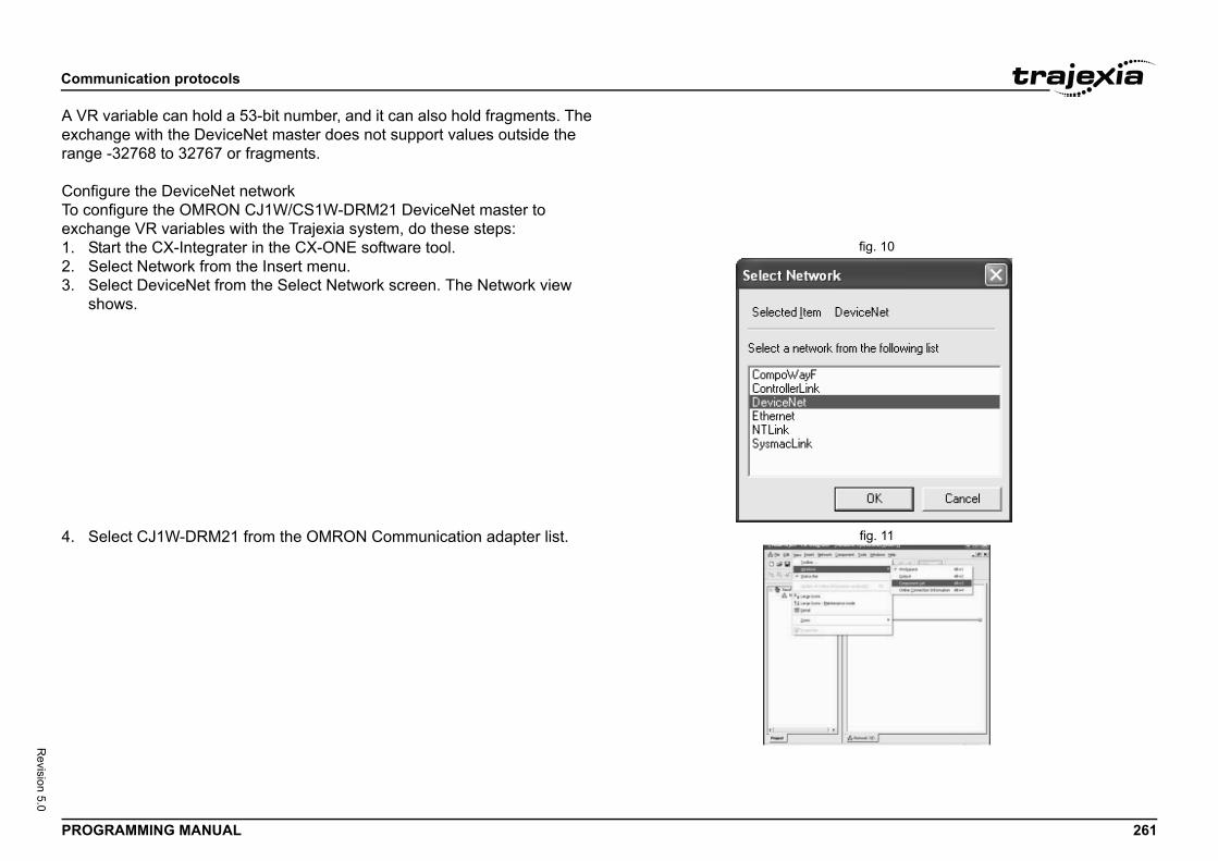
Comm
PROG 261
Revision 5.0
A VRexcharange
ConfiTo coexcha
fig. 101. S2. S3. S
sh
fig. 114. S
unication protocols
RAMMING MANUAL
variable can hold a 53-bit number, and it can also hold fragments. The nge with the DeviceNet master does not support values outside the -32768 to 32767 or fragments.
gure the DeviceNet networknfigure the OMRON CJ1W/CS1W-DRM21 DeviceNet master to nge VR variables with the Trajexia system, do these steps:
tart the CX-Integrater in the CX-ONE software tool.elect Network from the Insert menu.elect DeviceNet from the Select Network screen. The Network view ows.
elect CJ1W-DRM21 from the OMRON Communication adapter list.
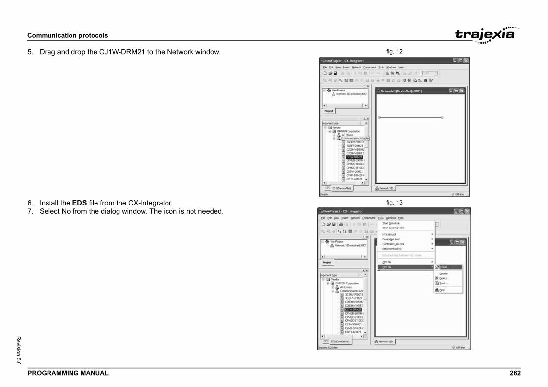
Comm
PROG 262
Revision 5.0
fig. 125. D
fig. 136. In7. S
unication protocols
RAMMING MANUAL
rag and drop the CJ1W-DRM21 to the Network window.
stall the EDS file from the CX-Integrator.elect No from the dialog window. The icon is not needed.
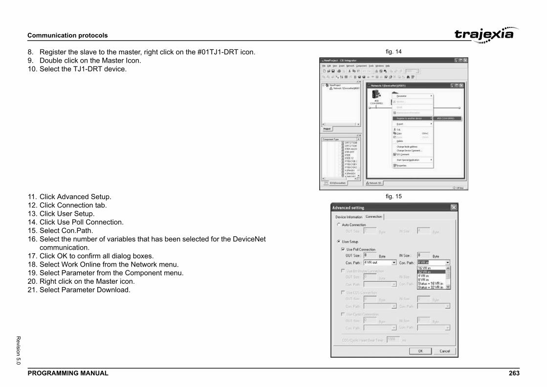
Comm
PROG 263
Revision 5.0
fig. 148. R9. D10. S
fig. 1511. C12. C13. C14. C15. S16. S
co17. C18. S19. S20. R21. S
unication protocols
RAMMING MANUAL
egister the slave to the master, right click on the #01TJ1-DRT icon.ouble click on the Master Icon.elect the TJ1-DRT device.
lick Advanced Setup.lick Connection tab.lick User Setup.lick Use Poll Connection.elect Con.Path.elect the number of variables that has been selected for the DeviceNet mmunication.
lick OK to confirm all dialog boxes.elect Work Online from the Network menu.elect Parameter from the Component menu.ight click on the Master icon.elect Parameter Download.
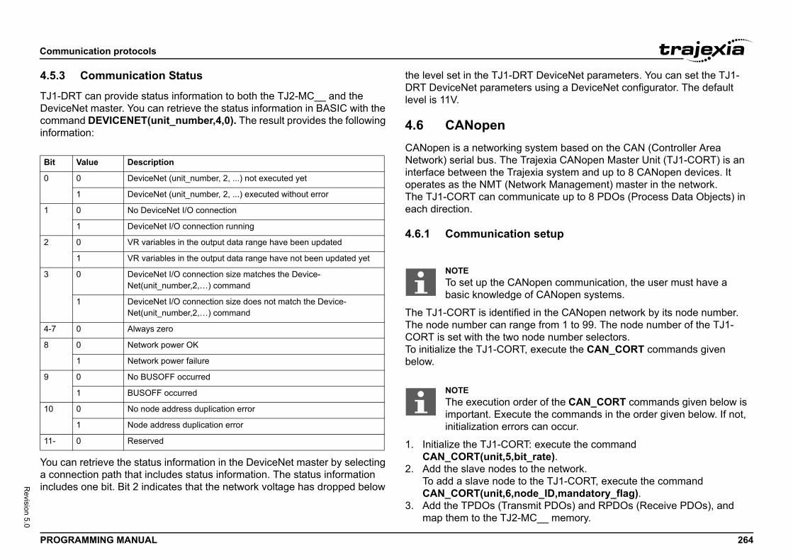
Comm
PROG 264
Revision 5.0
4.5.3
TJ1-DDeviccomminform/i
You ca coninclud
DeviceNet parameters. You can set the TJ1-sing a DeviceNet configurator. The default
tem based on the CAN (Controller Area jexia CANopen Master Unit (TJ1-CORT) is an ia system and up to 8 CANopen devices. It rk Management) master in the network.icate up to 8 PDOs (Process Data Objects) in
etup
n the CANopen network by its node number. from 1 to 99. The node number of the TJ1-e number selectors.
xecute the CAN_CORT commands given
xecute the command ate).e network.e TJ1-CORT, execute the command _ID,mandatory_flag).it PDOs) and RPDOs (Receive PDOs), and __ memory.
Bit
0
1
2
3
4-7
8
9
10
11-
en communication, the user must have a CANopen systems.
of the CAN_CORT commands given below is he commands in the order given below. If not, an occur.
unication protocols
RAMMING MANUAL
Communication Status
RT can provide status information to both the TJ2-MC__ and the eNet master. You can retrieve the status information in BASIC with the and DEVICENET(unit_number,4,0). The result provides the following ation:
an retrieve the status information in the DeviceNet master by selecting nection path that includes status information. The status information es one bit. Bit 2 indicates that the network voltage has dropped below
the level set in the TJ1-DRT DRT DeviceNet parameters ulevel is 11V.
4.6 CANopenCANopen is a networking sysNetwork) serial bus. The Trainterface between the Trajexoperates as the NMT (NetwoThe TJ1-CORT can communeach direction.
4.6.1 Communication s
The TJ1-CORT is identified iThe node number can rangeCORT is set with the two nodTo initialize the TJ1-CORT, ebelow.
1. Initialize the TJ1-CORT: eCAN_CORT(unit,5,bit_r
2. Add the slave nodes to thTo add a slave node to thCAN_CORT(unit,6,node
3. Add the TPDOs (Transmmap them to the TJ2-MC
Value Description
0 DeviceNet (unit_number, 2, ...) not executed yet
1 DeviceNet (unit_number, 2, ...) executed without error
0 No DeviceNet I/O connection
1 DeviceNet I/O connection running
0 VR variables in the output data range have been updated
1 VR variables in the output data range have not been updated yet
0 DeviceNet I/O connection size matches the Device-Net(unit_number,2,…) command
1 DeviceNet I/O connection size does not match the Device-Net(unit_number,2,…) command
0 Always zero
0 Network power OK
1 Network power failure
0 No BUSOFF occurred
1 BUSOFF occurred
0 No node address duplication error
1 Node address duplication error
0 Reserved
NOTETo set up the CANopbasic knowledge of
NOTEThe execution orderimportant. Execute tinitialization errors c
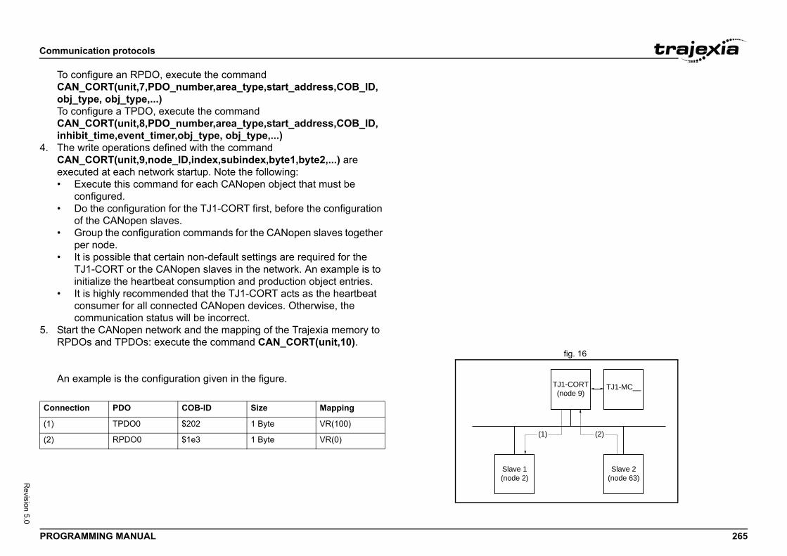
Comm
PROG 265
Revision 5.0
ToCoToCin
4. TCe•
•
•
•
•
5. SR
fig. 16
A/i
Slave 2(node 63)
TJ1-MC__TJ1-CORT(node 9)
(1) (2)
Conn
(1)
(2)
unication protocols
RAMMING MANUAL
configure an RPDO, execute the command AN_CORT(unit,7,PDO_number,area_type,start_address,COB_ID, bj_type, obj_type,...) configure a TPDO, execute the command
AN_CORT(unit,8,PDO_number,area_type,start_address,COB_ID, hibit_time,event_timer,obj_type, obj_type,...)
he write operations defined with the command AN_CORT(unit,9,node_ID,index,subindex,byte1,byte2,...) are xecuted at each network startup. Note the following:
Execute this command for each CANopen object that must be configured. Do the configuration for the TJ1-CORT first, before the configuration of the CANopen slaves.Group the configuration commands for the CANopen slaves together per node.It is possible that certain non-default settings are required for the TJ1-CORT or the CANopen slaves in the network. An example is to initialize the heartbeat consumption and production object entries.It is highly recommended that the TJ1-CORT acts as the heartbeat consumer for all connected CANopen devices. Otherwise, the communication status will be incorrect.
tart the CANopen network and the mapping of the Trajexia memory to PDOs and TPDOs: execute the command CAN_CORT(unit,10).
n example is the configuration given in the figure.
Slave 1(node 2)
ection PDO COB-ID Size Mapping
TPDO0 $202 1 Byte VR(100)
RPDO0 $1e3 1 Byte VR(0)
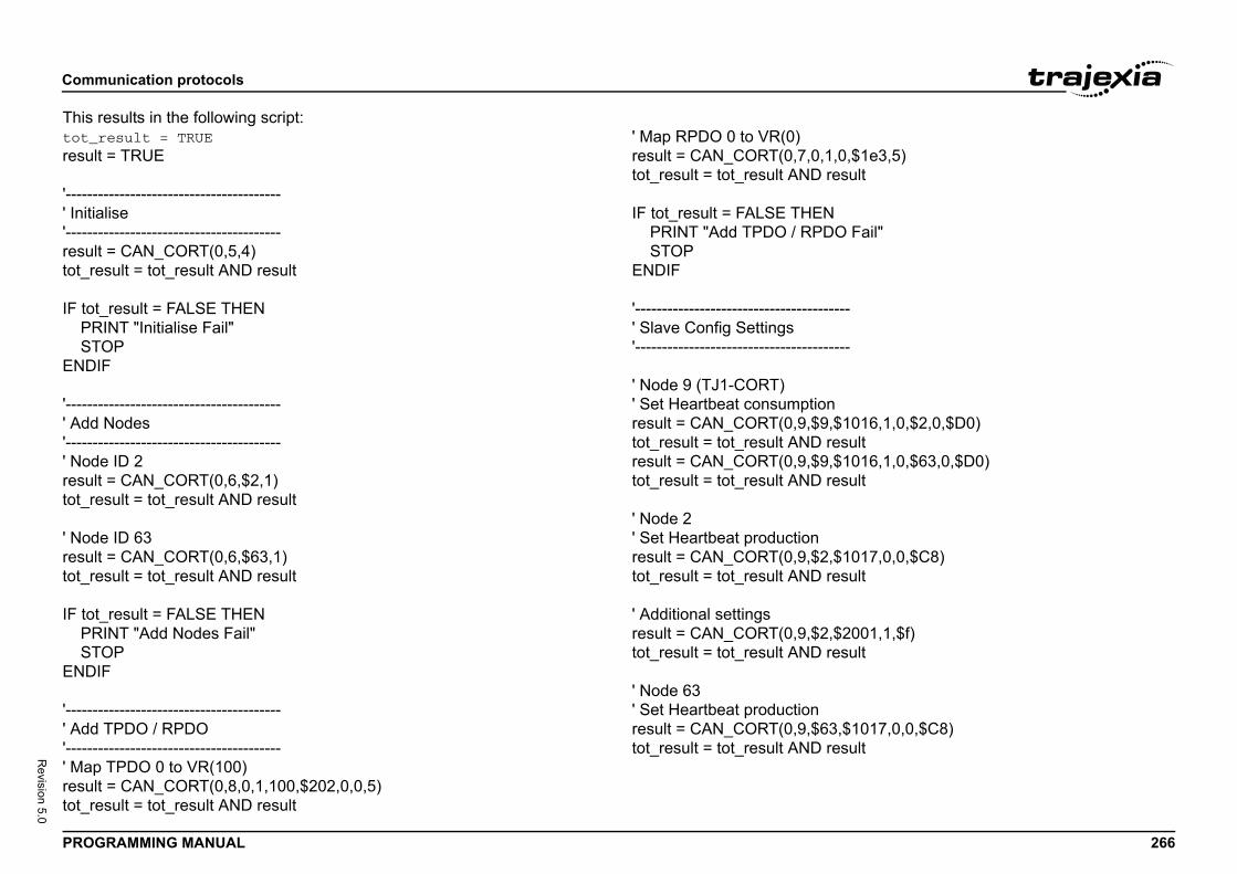
Comm
PROG 266
Revision 5.0
This rtot_rresult
'-------' Initia'-------resulttot_re
IF tot PR STENDI
'-------' Add'-------' Nodresulttot_re
' Nodresulttot_re
IF tot PR STENDI
'-------' Add'-------' Mapresulttot_re
0,$1e3,5)sult
Fail"
--
--
1016,1,0,$2,0,$D0)sult1016,1,0,$63,0,$D0)sult
1017,0,0,$C8)sult
2001,1,$f)sult
,$1017,0,0,$C8)sult
unication protocols
RAMMING MANUAL
esults in the following script:esult = TRUE
= TRUE
---------------------------------lise--------------------------------- = CAN_CORT(0,5,4)sult = tot_result AND result
_result = FALSE THENINT "Initialise Fail"OPF
--------------------------------- Nodes---------------------------------e ID 2 = CAN_CORT(0,6,$2,1)sult = tot_result AND result
e ID 63 = CAN_CORT(0,6,$63,1)sult = tot_result AND result
_result = FALSE THENINT "Add Nodes Fail"OPF
--------------------------------- TPDO / RPDO--------------------------------- TPDO 0 to VR(100) = CAN_CORT(0,8,0,1,100,$202,0,0,5)sult = tot_result AND result
' Map RPDO 0 to VR(0)result = CAN_CORT(0,7,0,1,tot_result = tot_result AND re
IF tot_result = FALSE THEN PRINT "Add TPDO / RPDO STOPENDIF
'--------------------------------------' Slave Config Settings'--------------------------------------
' Node 9 (TJ1-CORT)' Set Heartbeat consumptionresult = CAN_CORT(0,9,$9,$tot_result = tot_result AND reresult = CAN_CORT(0,9,$9,$tot_result = tot_result AND re
' Node 2' Set Heartbeat productionresult = CAN_CORT(0,9,$2,$tot_result = tot_result AND re
' Additional settingsresult = CAN_CORT(0,9,$2,$tot_result = tot_result AND re
' Node 63' Set Heartbeat productionresult = CAN_CORT(0,9,$63tot_result = tot_result AND re
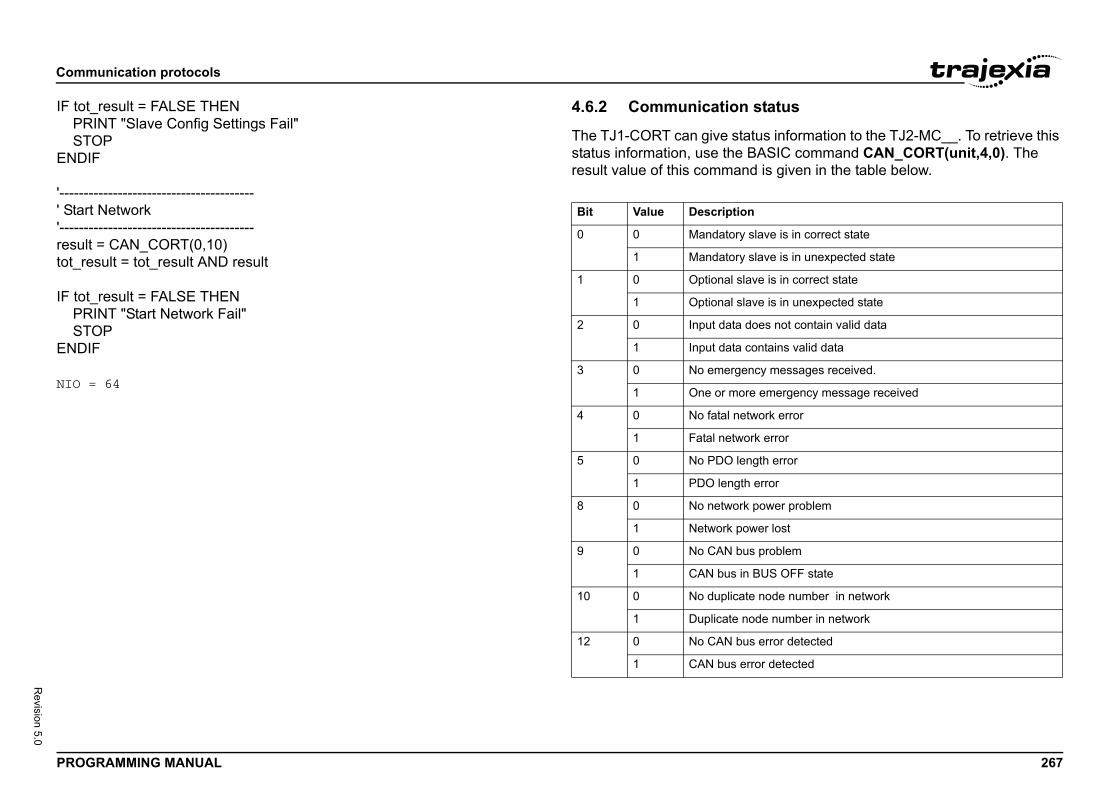
Comm
PROG 267
Revision 5.0
IF tot PR STENDI
'-------' Star'-------resulttot_re
IF tot PR STENDI
NIO =
tatus
s information to the TJ2-MC__. To retrieve this ASIC command CAN_CORT(unit,4,0). The is given in the table below.
ave is in correct state
ave is in unexpected state
e is in correct state
e is in unexpected state
es not contain valid data
ntains valid data
y messages received.
emergency message received
ork error
error
th error
rror
ower problem
er lost
problem
US OFF state
node number in network
e number in network
error detected
r detected
unication protocols
RAMMING MANUAL
_result = FALSE THENINT "Slave Config Settings Fail"OPF
---------------------------------t Network--------------------------------- = CAN_CORT(0,10)sult = tot_result AND result
_result = FALSE THENINT "Start Network Fail"OPF
64
4.6.2 Communication s
The TJ1-CORT can give statustatus information, use the Bresult value of this command/i
Bit Value Description
0 0 Mandatory sl
1 Mandatory sl
1 0 Optional slav
1 Optional slav
2 0 Input data do
1 Input data co
3 0 No emergenc
1 One or more
4 0 No fatal netw
1 Fatal network
5 0 No PDO leng
1 PDO length e
8 0 No network p
1 Network pow
9 0 No CAN bus
1 CAN bus in B
10 0 No duplicate
1 Duplicate nod
12 0 No CAN bus
1 CAN bus erro
Comm
PROG 268
Revision 5.0
4.6.3
Whenwith t1. To
e2. To
DCEastWu
3. ToeCE
4. TocoE
4.7The Mmotio
The ncycle• F• F• F
The c• T
sl• T
s a synchronization clock and broadcast all the slaves execute the commands at the
is transferred at a lower rate, for example the eters.
mands to address MECHATROLINK-II slave
mand resets one alarm in a o Driver via a MECHATROLINK-II message.nd sets to on one output in a remote odule.
mapping/O Unit is an interface for data exchange ATROLINK-II Master Unit and SmartSlice I/O
t requires strict control of the I/O timing, refer also contains some useful examples.
MECHATROLINK-II address to be identified on ork. With this address, the TJ2-MC__ an exchange I/O data with the GRT1-ML2.
unication protocols
RAMMING MANUAL
Communication operation
the communication is in progress, specific data can be exchanged he CAN_CORT command. set the CANopen network state to pre-operational or operational,
xecute the command CAN_CORT(unit,11,mode). read the value of an object of a CANopen node with an SDO (Service
ata Object) command, execute the command AN_CORT(unit,12,node_ID,index,subindex,VR_address).ach byte of the return value occupies one VR address. The first ddress (VR_address) contains the SDO response byte. The data read arts at VR_address + 1.hen the SDO response is not 0, the error information from the node
nit starts at VR_address + 1. write a value to an object of a CANopen node with an SDO command,
xecute the command AN_CORT(unit,13,node_ID,index,subindex,VR_address,data_len).ach VR address is interpreted as one byte of the value that is written. read the EMCY (emergency message from a node, execute the mmand CAN_CORT(unit,14,node_ID,VR_address).
ach byte of the 8 bytes occupies 1 VR address.
MECHATROLINK-II ECHATROLINK-II protocol is a serial bus that is made to control
n in a deterministic way.
umber of MECHATROLINK-II devices determines the data exchange time:or 1 to 4 devices the cycle time can be 0.5 ms, 1 ms or 2 ms.or 5 to 8 devices the cycle time can be 1 ms or 2 ms.or 9 to 16 devices the cycle time is 2 ms.
yclic transmission has two stages:he TJ1-ML__ sends the reference command to the MECHATROLINK-II aves.he slaves send feedback and status information to the TJ1-ML__.
The MECHATROLINK-II usemessaging to make sure thatsame time.
In addition, other informationreading and writing of param
There are specific BASIC comunits directly.• DRIVE_CLEAR: This com
MECHATROLINK-II Serv• OP(45,ON): This comma
MECHATROLINK-II I/O m
4.8 GRT1-ML2 I/O The GRT1-ML2 SmartSlice Ibetween a TJ1-ML__ MECHUnits.If you plan data exchange thato appendix A. This appendix
4.8.1 Unit numbers
The GRT1-ML2 must have a the MECHATROLINK-II netwconnected to the TJ1-ML__ c

Comm
PROG 269
Revision 5.0
4.8.2
The IcontroTJ2-M• T• T
The Ithe Gwith aaddre
The T
unication protocols
RAMMING MANUAL
SmartSlice I/O mapping
/O data of the SmartSlice I/O Units is transferred to the TJ2-MC__ ller. Then the data is automatically mapped in the I/O memory of the C__. The mapping is determined by:
he type of the SmartSlice I/O Unithe order of the SmartSlice I/O Units
/O data from GRT1-ML2 units is mapped in the TJ2-MC__ in order of RT1-ML2 addresses. For example, the I/O data of a GRT1-ML2 unit ddress 67 hex is mapped before the I/O data of a GRT1-ML2 unit with ss 68 hex.
J2-MC__ allocates digital I/O points in blocks of 32 points.
NOTEThe GRT1-ML2 does not support the on-line configuration of SmartSlice I/O Units. However, other communications units can change the parameters of a SmartSlice I/O Unit and store this con-figuration in the SmartSlice I/O Unit.
NOTEIf the GRT1-ML2 configuration contains non-supported SmartSlice I/O Units or SmartSlice I/O Units configured to consume a non-default amount of I/O data, the MECHATROLINK-II connection to the GRT1-ML2 is refused, and it cannot be operated.
NOTEThe automatic I/O mapping of SmartSlice I/O Units in the exam-ples given below assumes that each SmartSlice I/O Unit has the default I/O memory settings.
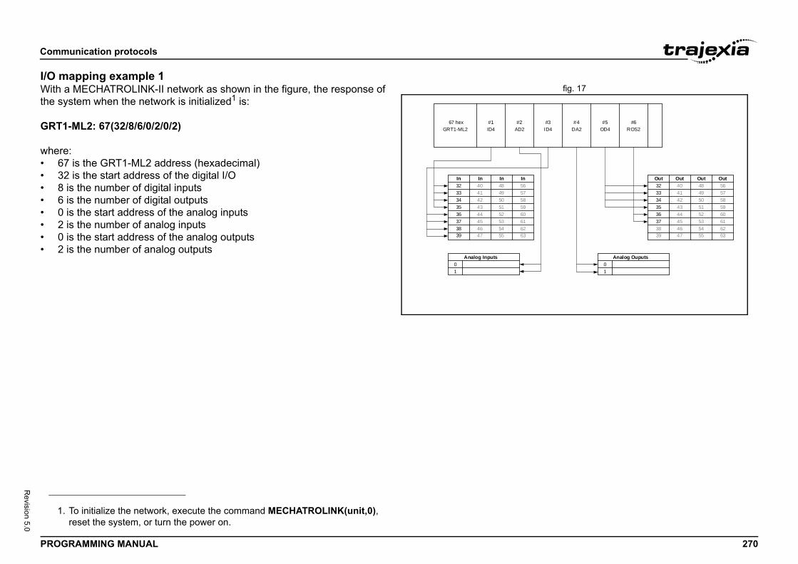
Comm
PROG 270
Revision 5.0
I/O mfig. 17With
the sy
GRT1
where• 6• 3• 8• 6• 0• 2• 0• 2
#3 #4 #5 #6
Out3233343536373839
Analog Ouputs01
Out4041424344454647
Out4849505152535455
Out5657585960616263
ID4 DA2 OD4 ROS2
1.
unication protocols
RAMMING MANUAL
apping example 1a MECHATROLINK-II network as shown in the figure, the response of stem when the network is initialized1 is:
-ML2: 67(32/8/6/0/2/0/2)
:7 is the GRT1-ML2 address (hexadecimal)2 is the start address of the digital I/O is the number of digital inputs is the number of digital outputs is the start address of the analog inputs is the number of analog inputs is the start address of the analog outputs is the number of analog outputs
67 hex #1 #2
In3233343536373839
Analog Inputs01
4041424344454647
4849505152535455
5657585960616263
In In In
GRT1-ML2 ID4 AD2
To initialize the network, execute the command MECHATROLINK(unit,0), reset the system, or turn the power on.
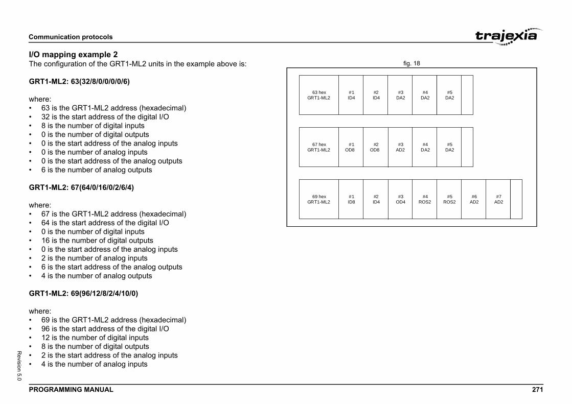
Comm
PROG 271
Revision 5.0
I/O mfig. 18The c
GRT1
where• 6• 3• 8• 0• 0• 0• 0• 6
GRT1
where• 6• 6• 0• 1• 0• 2• 6• 4
GRT1
where• 6• 9• 1• 8• 2• 4
#3 #4
#4#3
#5
#5
#5#4#3 #6 #7
DA2 DA2 DA2
AD2 DA2 DA2
OD4 ROS2 ROS2 AD2 AD2
unication protocols
RAMMING MANUAL
apping example 2onfiguration of the GRT1-ML2 units in the example above is:
-ML2: 63(32/8/0/0/0/0/6)
:3 is the GRT1-ML2 address (hexadecimal)2 is the start address of the digital I/O is the number of digital inputs is the number of digital outputs is the start address of the analog inputs is the number of analog inputs is the start address of the analog outputs is the number of analog outputs
-ML2: 67(64/0/16/0/2/6/4)
:7 is the GRT1-ML2 address (hexadecimal)4 is the start address of the digital I/O is the number of digital inputs6 is the number of digital outputs is the start address of the analog inputs is the number of analog inputs is the start address of the analog outputs is the number of analog outputs
-ML2: 69(96/12/8/2/4/10/0)
:9 is the GRT1-ML2 address (hexadecimal)6 is the start address of the digital I/O2 is the number of digital inputs is the number of digital outputs is the start address of the analog inputs is the number of analog inputs
63 hex #1 #2
67 hex #1 #2
69 hex #1 #2
GRT1-ML2
GRT1-ML2
GRT1-ML2
ID4 ID4
OD8 OD8
ID8 ID4
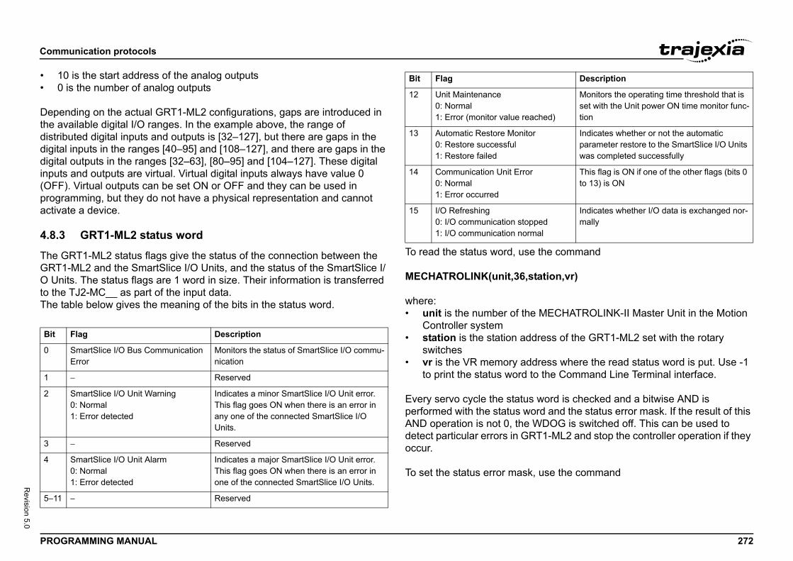
Comm
PROG 272
Revision 5.0
• 1• 0
Depethe avdistribdigitadigitainputs(OFFprogractiva
4.8.3
The GGRT1O Unto theThe t/i
the command
ation,vr)
MECHATROLINK-II Master Unit in the Motion
ress of the GRT1-ML2 set with the rotary
ress where the read status word is put. Use -1 the Command Line Terminal interface.
word is checked and a bitwise AND is rd and the status error mask. If the result of this
DOG is switched off. This can be used to T1-ML2 and stop the controller operation if they
use the command
Bit
0
1
2
3
4
5−11
hed)
Monitors the operating time threshold that is set with the Unit power ON time monitor func-tion
Indicates whether or not the automatic parameter restore to the SmartSlice I/O Units was completed successfully
This flag is ON if one of the other flags (bits 0 to 13) is ON
edal
Indicates whether I/O data is exchanged nor-mally
Description
unication protocols
RAMMING MANUAL
0 is the start address of the analog outputs is the number of analog outputs
nding on the actual GRT1-ML2 configurations, gaps are introduced in ailable digital I/O ranges. In the example above, the range of uted digital inputs and outputs is [32–127], but there are gaps in the
l inputs in the ranges [40–95] and [108–127], and there are gaps in the l outputs in the ranges [32–63], [80–95] and [104–127]. These digital and outputs are virtual. Virtual digital inputs always have value 0
). Virtual outputs can be set ON or OFF and they can be used in amming, but they do not have a physical representation and cannot te a device.
GRT1-ML2 status word
RT1-ML2 status flags give the status of the connection between the -ML2 and the SmartSlice I/O Units, and the status of the SmartSlice I/
its. The status flags are 1 word in size. Their information is transferred TJ2-MC__ as part of the input data.able below gives the meaning of the bits in the status word.
To read the status word, use
MECHATROLINK(unit,36,st
where:• unit is the number of the
Controller system• station is the station add
switches• vr is the VR memory add
to print the status word to
Every servo cycle the status performed with the status woAND operation is not 0, the Wdetect particular errors in GRoccur.
To set the status error mask,
Flag Description
SmartSlice I/O Bus Communication Error
Monitors the status of SmartSlice I/O commu-nication
− Reserved
SmartSlice I/O Unit Warning0: Normal1: Error detected
Indicates a minor SmartSlice I/O Unit error. This flag goes ON when there is an error in any one of the connected SmartSlice I/O Units.
− Reserved
SmartSlice I/O Unit Alarm0: Normal1: Error detected
Indicates a major SmartSlice I/O Unit error. This flag goes ON when there is an error in one of the connected SmartSlice I/O Units.
− Reserved
12 Unit Maintenance0: Normal1: Error (monitor value reac
13 Automatic Restore Monitor0: Restore successful1: Restore failed
14 Communication Unit Error0: Normal1: Error occurred
15 I/O Refreshing0: I/O communication stopp1: I/O communication norm
Bit Flag
Comm
PROG 273
Revision 5.0
MECH
where• u
C• s
sw• v
The s
MECH
whereMECHmaskWDO0000 error
4.8.4
The tO UnThis aturne• To
se• To
isaco
tablere the power of the GRT1-ML2 and the d set unit dipswitch 1 (REGS) on the
If the registration table is refreshed, the old
that is registered contains these items:ice I/O Units connected to the GRT1-ML2.ut, number of bits) of each SmartSlice I/O Unit.
does not contain the model numbers of the
o register the I/O configuration table when all are communicating, that is, when the TS LED
unication protocols
RAMMING MANUAL
ATROLINK(unit,37,station,value)
:nit is the number of the MECHATROLINK-II Master Unit in the Motion ontroller systemtation is the station address of the GRT1-ML2 set with the rotary
itchesalue is the value of the status error mask that must be set.
tatus error mask value can be read back by means of the command
ATROLINK(unit,39,station,vr)
the arguments of the command are the same as for the command ATROLINK(unit,36,station,vr). The default value of the status error
after the controller is turned on or reset is 4000 hex. This disables the G when an error occurs in the GRT1-ML2. 4000 hex equals 0100 0000 0000 binary. Bit 14 is the overall error bit, which is set to 1 when an occurs.
Table registration
able registration function registers the configuration of the SmartSlice I/its that are connected to the GRT1-ML2 in a table in the GRT1-ML2. llows for a comparison of the actual configuration when the power is
d on with the registered configuration. enable the registered table, make sure that unit dipswitch 1 (REGS) is t to ON before the power is turned on. disable the registered table, make sure that unit dipswitch 1 (REGS)
set to OFF before the power is turned on. In this case, the GRT1-ML2 utomatically detects the actual I/O configuration and starts the mmunication.
Create a new registrationTo register the table, make suSmartSlice I/O Units is on, anGRT1-ML2 from OFF to ON.registration table is erased.
The configuration information• The order of the SmartSl• The I/O size (input or outp
The configuration informationSmartSlice I/O Units.
NOTEIt is recommended tSmartSlice I/O Unitsis lit green.
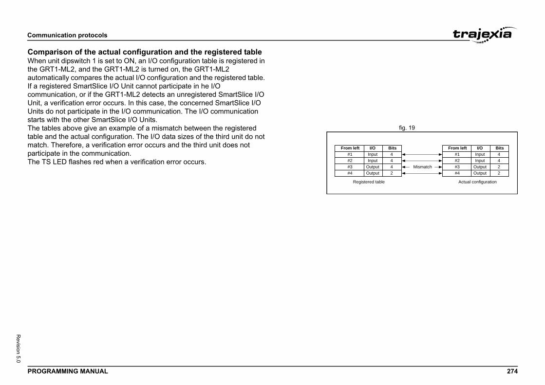
Comm
PROG 274
Revision 5.0
ComWhenthe GautomIf a recommUnit, Unitsstarts
fig. 19The ttable matchparticThe T
From left#1#2#3Mismatch#4
I/OInputInput
OutputOutput
Bits4422
I/Onputnpututpututput
ed table Actual configuration
Bits4442
unication protocols
RAMMING MANUAL
parison of the actual configuration and the registered table unit dipswitch 1 is set to ON, an I/O configuration table is registered in RT1-ML2, and the GRT1-ML2 is turned on, the GRT1-ML2 atically compares the actual I/O configuration and the registered table. gistered SmartSlice I/O Unit cannot participate in he I/O unication, or if the GRT1-ML2 detects an unregistered SmartSlice I/O
a verification error occurs. In this case, the concerned SmartSlice I/O do not participate in the I/O communication. The I/O communication with the other SmartSlice I/O Units.ables above give an example of a mismatch between the registered and the actual configuration. The I/O data sizes of the third unit do not . Therefore, a verification error occurs and the third unit does not
ipate in the communication.S LED flashes red when a verification error occurs.
From left#1#2#3#4
II
OO
Register
Comm
PROG 275
Revision 5.0
4.9Etheroptimenablinvertrealtim
CANThe can opcommparamdictioTo coand speriodwhichcommpositicommspeci
DistrEtherdata edevictimingAll desynchServo
NodeEachaddreIO ma
odes not supporting address switches or ero.ddress switches
assignement, the address depends on the twork. The node closests to the EtherCAT ress.ing, the node address is based on the address
ve the node address is assigned as follows:
unication protocols
RAMMING MANUAL
EtherCATCAT is an Ethernet-based ultra-high-speed field bus system. It izes usage of the 100-Mbps duplex communications bandwidth to e high-speed control of motor drives, including servo drives and ers. It can also be used to control sensors, analog I/O, and other I/O in e, all using the same communications protocol.
open over EtherCAT (CoE)ontroller exchanges data with the slave on EtherCAT using CANopen , en network standard. CANopen over EtherCAT (CoE) is used as the unications protocol in EtherCAT communications. With CoE, the eters and control data held by the slaves are specified using an object
nary (OD), which is based on the CANopen standard.mmunicate the data between the controller/communications master laves, two methods are used: process data objects (PDOs), which ically exchange data in realtime, and service data objects (SDOs), exchange data when required. The controller uses PDO unications for commands to refresh data, such as data for servomotor
on control, on a fixed control cycle. It uses SDO communications for ands to read and write data, such as for parameter transfers, at
fied times.
ibuted Clock (DC)CAT uses distributed clocks (DCs) to ensure time synchronization in xchange between the communications master and the slaves. The
es connected to EtherCAT share time information and synchronize the of device operations based on the distributed clock in each device.vices perform control operations based on the distributed clocks to ronize all devices. When the controller is used with Accurax G5-series Drives, distributed clocks are used for synchronization.
addressing node on the EtherCAT network will get a node address assigned. This ss is used to assign an axis number (for Servo Drives) or to define the pping (for IO). The address can be assigned in two ways:
• Automatically assigned: naddress switches set to z
• Configured: nodes with a
In case of automatic addressposition of the node in the nemaster will get the lowest addIn case of configured addressset by the address switches.Depending on the type of sla
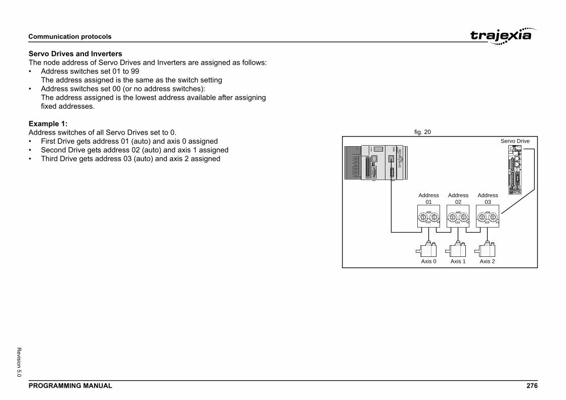
Comm
PROG 276
Revision 5.0
ServoThe n• A
T• A
Tfix
Examfig. 20Addre
• F• S• T
Address01
Axis 0 Axis 1 Axis 2
Address02
Address03
Servo Drive
ADR
x10 x1
ADR
x10 x1
ADR
x10 x1
unication protocols
RAMMING MANUAL
Drives and Invertersode address of Servo Drives and Inverters are assigned as follows:ddress switches set 01 to 99he address assigned is the same as the switch settingddress switches set 00 (or no address switches):he address assigned is the lowest address available after assigning ed addresses.
ple 1:ss switches of all Servo Drives set to 0.
irst Drive gets address 01 (auto) and axis 0 assignedecond Drive gets address 02 (auto) and axis 1 assignedhird Drive gets address 03 (auto) and axis 2 assigned
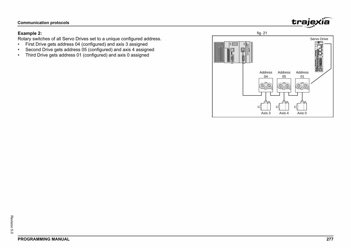
Comm
PROG 277
Revision 5.0
fig. 21ExamRotar• F• S• T
Address04
Axis 3 Axis 4 Axis 0
Address05
Address01
Servo Drive
ADR
x10 x1
ADR
x10 x1
ADR
x10 x1
unication protocols
RAMMING MANUAL
ple 2:y switches of all Servo Drives set to a unique configured address.irst Drive gets address 04 (configured) and axis 3 assignedecond Drive gets address 05 (configured) and axis 4 assignedhird Drive gets address 01 (configured) and axis 0 assigned
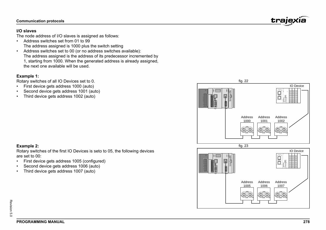
Comm
PROG 278
Revision 5.0
I/O slThe n• A
T• A
T1th
Examfig. 22Rotar
• F• S• T
fig. 23ExamRotarare se• F• S• T
Address1000
Address1001
Address1002
IO Device
ADR
x10 x1
ADR
x10 x1
ADR
x10 x1
Address1005
Address1006
Address1007
IO Device
ADR
x10 x1
ADR
x10 x1
ADR
x10 x1
unication protocols
RAMMING MANUAL
avesode address of I/O slaves is assigned as follows:ddress switches set from 01 to 99he address assigned is 1000 plus the switch settingddress switches set to 00 (or no address switches available):he address assigned is the address of its predecessor incremented by , starting from 1000. When the generated address is already assigned, e next one available will be used.
ple 1:y switches of all IO Devices set to 0.irst device gets address 1000 (auto)econd device gets address 1001 (auto)hird device gets address 1002 (auto)
ple 2:y switches of the first IO Devices is seto to 05, the following devices t to 00:
irst device gets address 1005 (configured)econd device gets address 1006 (auto)hird device gets address 1007 (auto)
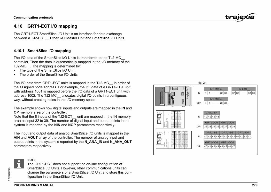
Comm
PROG 279
Revision 5.0
4.10The Gbetwe
4.10.
The IcontroTJ2-M• T• T
fig. 24The Ithe aswith aaddreway,
The eOP mNote area syste
The inAIN aoutpuparam
4 ID4
0 1 30 31 32 33 38 39TJ2-MC64 TJ2-ECT__
0 1 30 31TJ2-MC64
IN
OP
40 41 42 43GRT1-ID4
32 33 34 35GRT1-OD4
36 37 38 39GRT1-OD4
IN
OP
40 41 42 43GRT1-ID8
40 41 42 43GRT1-ID8
40 41 42 43GRT1-ID4
40 41 42 43GRT1-OD4
44 45 46 47GRT1-OD4
IN
OP
unication protocols
RAMMING MANUAL
GRT1-ECT I/O mappingRT1-ECT SmartSlice I/O Unit is an interface for data exchange en a TJ2-ECT__ EtherCAT Master Unit and SmartSlice I/O Units.
1 SmartSlice I/O mapping
/O data of the SmartSlice I/O Units is transferred to the TJ2-MC__ ller. Then the data is automatically mapped in the I/O memory of the C__. The mapping is determined by:
he type of the SmartSlice I/O Unithe order of the SmartSlice I/O Units
/O data from GRT1-ECT units is mapped in the TJ2-MC__ in order of signed node address. For example, the I/O data of a GRT1-ECT unit ddress 1001 is mapped before the I/O data of a GRT1-ECT unit with ss 1002. The TJ2-MC__ allocates digital I/O points in a contiguous
without creating holes in the I/O memory space.
xample shows how digital inputs and outputs are mapped in the IN and emory area of the controller.that the 8 inputs of the TJ2-ECT__ unit are mapped in the IN memory as input 32 to 39. The number of digital input and output points in the m is reported by the NIN and NOP parameters respectively.
put and output data of analog SmartSlice I/O units is mapped in the nd AOUT array of the controller. The number of analog input and t points in the system is reported by the N_ANA_IN and N_ANA_OUT eters respectively.
OD4OD4 ID4
ODID8ID8 OD4
NOTEThe GRT1-ECT does not support the on-line configuration of SmartSlice I/O Units. However, other communications units can change the parameters of a SmartSlice I/O Unit and store this con-figuration in the SmartSlice I/O Unit.
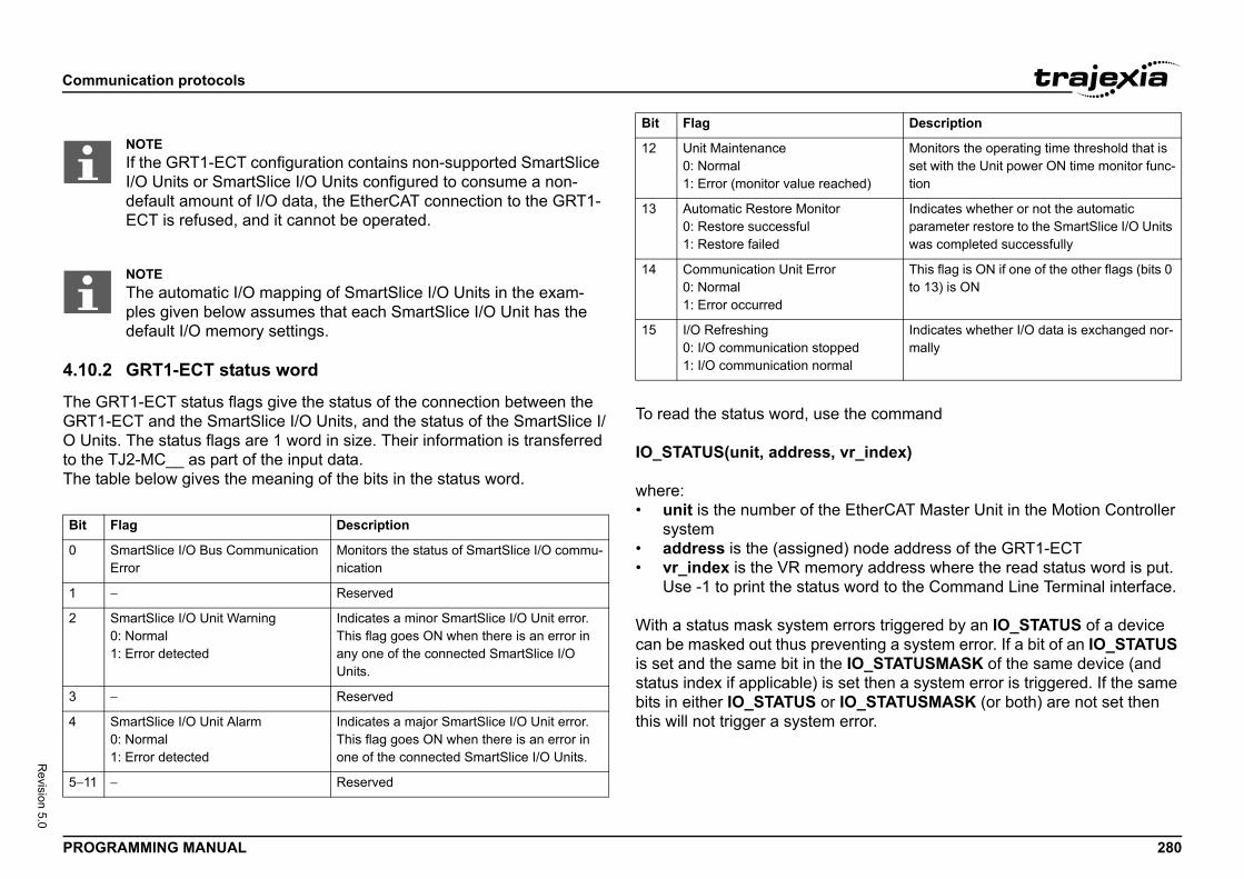
Comm
PROG 280
Revision 5.0
4.10.
The GGRT1O Unto theThe t/i
the command
r_index)
EtherCAT Master Unit in the Motion Controller
) node address of the GRT1-ECTory address where the read status word is put. word to the Command Line Terminal interface.
rrors triggered by an IO_STATUS of a device enting a system error. If a bit of an IO_STATUS IO_STATUSMASK of the same device (and et then a system error is triggered. If the same O_STATUSMASK (or both) are not set then rror.
Bit
0
1
2
3
4
5−11
hed)
Monitors the operating time threshold that is set with the Unit power ON time monitor func-tion
Indicates whether or not the automatic parameter restore to the SmartSlice I/O Units was completed successfully
This flag is ON if one of the other flags (bits 0 to 13) is ON
edal
Indicates whether I/O data is exchanged nor-mally
Description
unication protocols
RAMMING MANUAL
2 GRT1-ECT status word
RT1-ECT status flags give the status of the connection between the -ECT and the SmartSlice I/O Units, and the status of the SmartSlice I/
its. The status flags are 1 word in size. Their information is transferred TJ2-MC__ as part of the input data.able below gives the meaning of the bits in the status word.
To read the status word, use
IO_STATUS(unit, address, v
where:• unit is the number of the
system• address is the (assigned• vr_index is the VR mem
Use -1 to print the status
With a status mask system ecan be masked out thus previs set and the same bit in thestatus index if applicable) is sbits in either IO_STATUS or Ithis will not trigger a system e
NOTEIf the GRT1-ECT configuration contains non-supported SmartSlice I/O Units or SmartSlice I/O Units configured to consume a non-default amount of I/O data, the EtherCAT connection to the GRT1-ECT is refused, and it cannot be operated.
NOTEThe automatic I/O mapping of SmartSlice I/O Units in the exam-ples given below assumes that each SmartSlice I/O Unit has the default I/O memory settings.
Flag Description
SmartSlice I/O Bus Communication Error
Monitors the status of SmartSlice I/O commu-nication
− Reserved
SmartSlice I/O Unit Warning0: Normal1: Error detected
Indicates a minor SmartSlice I/O Unit error. This flag goes ON when there is an error in any one of the connected SmartSlice I/O Units.
− Reserved
SmartSlice I/O Unit Alarm0: Normal1: Error detected
Indicates a major SmartSlice I/O Unit error. This flag goes ON when there is an error in one of the connected SmartSlice I/O Units.
− Reserved
12 Unit Maintenance0: Normal1: Error (monitor value reac
13 Automatic Restore Monitor0: Restore successful1: Restore failed
14 Communication Unit Error0: Normal1: Error occurred
15 I/O Refreshing0: I/O communication stopp1: I/O communication norm
Bit Flag
Comm
PROG 281
Revision 5.0
To se
IO_S
where• u
sy• a• re
01
• vIn-1
• mva
The dreset GRT1overa
4.10.
The tI/O UThis aturne• To
se• To
isaco
tablere the power of the GRT1-ECT and the d set unit dipswitch 1 (REGS) on the
If the registration table is refreshed, the old
that is registered contains these items:ice I/O Units connected to the GRT1-ECT.ut, number of bits) of each SmartSlice I/O Unit.
does not contain the model numbers of the
o register the I/O configuration table when all are communicating, that is, when the TS LED
unication protocols
RAMMING MANUAL
t the status error mask, use the command
TATUSMASK(unit, address, read_write, vr_index or mask_value)
:nit is the number of the EtherCAT Master Unit in the Motion Controller stem
ddress is the (assigned) node address of the GRT1-ECTad_write
: Read status mask : Write status maskr_index (if read_write is 0)dex of the VR entry where the read status mask is copied to will print the results to the terminal.ask_value (if read_write is 1)lue of the status mask to be written
efault value of the status error mask after the controller is turned on or is 4000 hex. This disables the WDOG when an error occurs in the -ECT. 4000 hex equals 0100 0000 0000 0000 binary. Bit 14 is the ll error bit, which is set to 1 when an error occurs.
3 Table registration
able registration function registers the configuration of the SmartSlice nits that are connected to the GRT1-ECT in a table in the GRT1-ECT. llows for a comparison of the actual configuration when the power is
d on with the registered configuration. enable the registered table, make sure that unit dipswitch 1 (REGS) is t to ON before the power is turned on. disable the registered table, make sure that unit dipswitch 1 (REGS)
set to OFF before the power is turned on. In this case, the GRT1-ECT utomatically detects the actual I/O configuration and starts the mmunication.
Create a new registrationTo register the table, make suSmartSlice I/O Units is on, anGRT1-ECT from OFF to ON.registration table is erased.
The configuration information• The order of the SmartSl• The I/O size (input or outp
The configuration informationSmartSlice I/O Units.
NOTEIt is recommended tSmartSlice I/O Unitsis lit green.

Comm
PROG 282
Revision 5.0
ComWhenthe GautomIf a recommUnit, Unitsstarts
fig. 25The ttable matchparticThe T
From left#1#2#3Mismatch#4
I/OInputInput
OutputOutput
Bits4422
I/Onputnpututpututput
ed table Actual configuration
Bits4442
unication protocols
RAMMING MANUAL
parison of the actual configuration and the registered table unit dipswitch 1 is set to ON, an I/O configuration table is registered in RT1-ECT, and the GRT1-ECT is turned on, the GRT1-ECT atically compares the actual I/O configuration and the registered table. gistered SmartSlice I/O Unit cannot participate in he I/O unication, or if the GRT1-ECT detects an unregistered SmartSlice I/O
a verification error occurs. In this case, the concerned SmartSlice I/O do not participate in the I/O communication. The I/O communication with the other SmartSlice I/O Units.ables above give an example of a mismatch between the registered and the actual configuration. The I/O data sizes of the third unit do not . Therefore, a verification error occurs and the third unit does not
ipate in the communication.S LED flashes red when a verification error occurs.
From left#1#2#3#4
II
OO
Register

Exam
PROG 283
Revision 5.0
5This c• H• P
5.1
5.1.1
The por Ethis theThe S• C• C• C• A• S• S
How fig. 1When
progrprogrA TJ2on, it
fig. 2You cPriorithe eTo sebox a19 (loTo sebox.
ples and tips
RAMMING MANUAL
Examples and tipshapter gives 2 categories of examples and tips:ow-to’s.ractical examples.
How-to’s
Startup program
urpose of this program is to compare the detected MECHATROLINK-II erCAT configuration with the expected one (the expected configuration configuration existing in the moment you create the program).HELL program does these actions:hecks the number of nodes in the system.hecks that the node numbers agrees.hecks if all devices are connected and have power.ny non agreement, the program stops.ets the correct ATYPE as selected in the intelligent axis window.ets the mode, Run or Commisioning.
to set a startup program you add a new TJ2-MC__ to the solution in Trajexia Studio, 2 ams are created by default: the SHELL program, and an application am called APPLICATION.-MC__ can execute a program at startup: when the device is switched executes the program.an set the startup priority for a program in Trajexia Studio with the ty property in the Properties window. If you click the ellipsis button in dit field of this property, the StartUp Priority window shows.t the program to run at power up, select the Run at Power Up check nd select a priority in the list. Possible priority values are Default, 0 to w priority) or 20 and 21 (high priority).t the program not to run at startup, clear the Run at Power Up check
Exam
PROG 284
Revision 5.0
Exam'===='THE 'CON'VER'EXPE'IF YE'IF NO'THIS'PRIO'===='Start' Che' UnitIF NO PR STELSE IF ENENDI
4,0,0) THENss for unit 0, station 0"
ss for unit 0, station 0"
4,1,0) THENss for unit 0, station 1"
ss for unit 0, station 1"
4,2,0) THENss for unit 0, station 2"
ss for unit 0, station 2"
ples and tips
RAMMING MANUAL
ple============================================FIRST PART OF THE PROGRAMSISTS OF A CHECK SEQUENCE TOIFY THAT THE DETECTED AXIS CONFIGURATION IS THE
CTED ONE.S, THE PROGRAM FINISHES AND STARTS "APPLICATION".T, THE PROGRAM STOPS AND NO OTHER PROGRAM STARTS.
PROGRAM MUST BE SET TO RUN AT POWER UP IN 'A LOWRITY TASK (1 IN THIS EXAMPLE)============================================
MECHATROLINK Sectionck detected slaves 0T MECHATROLINK(0,3,0) THENINT "Error getting slave count for unit 0"OP
VR(0) <> 3 THENPRINT "Incorrect slave count for unit 0"STOPDIFF
IF NOT MECHATROLINK(0, PRINT "Error getting addre STOPELSE IF VR(0) <> 65 THEN PRINT "Incorrect addre STOP ENDIFENDIFIF NOT MECHATROLINK(0, PRINT "Error getting addre STOPELSE IF VR(0) <> 66 THEN PRINT "Incorrect addre STOP ENDIFENDIFIF NOT MECHATROLINK(0, PRINT "Error getting addre STOPELSE IF VR(0) <> 67 THEN PRINT "Incorrect addre STOP ENDIFENDIF' Set axis types' Unit 0ATYPE AXIS(0)=40ATYPE AXIS(1)=40ATYPE AXIS(2)=40' Set drives into run mode' Unit 0MECHATROLINK(0,20,65)MECHATROLINK(0,20,66)MECHATROLINK(0,20,67)
NOTEThe SHELL program by default runs at startup at priority 0.
NOTEOMRON recommends that the statement RUN “APPLICATION” is used in the Startup program to start your application program. The application program starts when the startup program is exe-cuted successfully and without errors.If you set an application program to “Run at startup” there is a risk that the machine starts if there is an error on the MECHA-TROLINK-II bus.
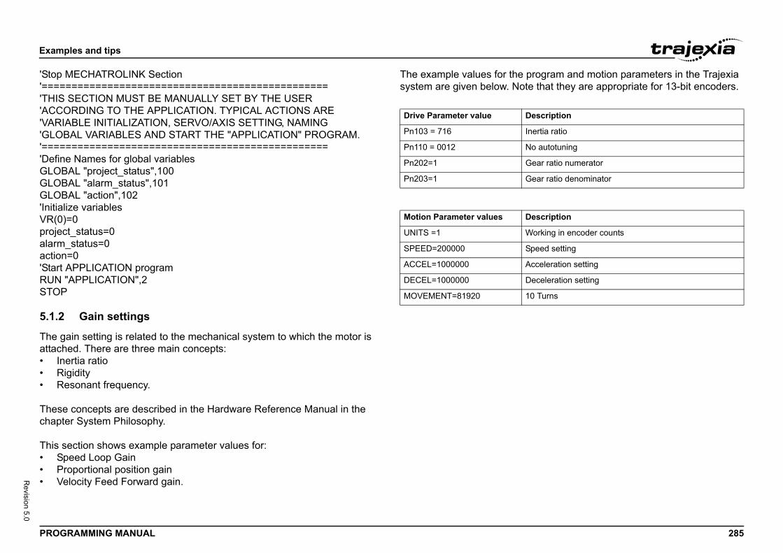
Exam
PROG 285
Revision 5.0
'Stop '===='THIS'ACC'VARI'GLO'===='DefinGLOBGLOBGLOB'InitiaVR(0projecalarmaction'StartRUN STOP
5.1.2
The gattach• In• R• R
Thesechapt
This s• S• P• V
rogram and motion parameters in the Trajexia that they are appropriate for 13-bit encoders.
escription
ertia ratio
o autotuning
ear ratio numerator
ear ratio denominator
escription
orking in encoder counts
peed setting
cceleration setting
eceleration setting
0 Turns
ples and tips
RAMMING MANUAL
MECHATROLINK Section============================================ SECTION MUST BE MANUALLY SET BY THE USERORDING TO THE APPLICATION. TYPICAL ACTIONS AREABLE INITIALIZATION, SERVO/AXIS SETTING, NAMINGBAL VARIABLES AND START THE "APPLICATION" PROGRAM.============================================e Names for global variablesAL "project_status",100AL "alarm_status",101AL "action",102
lize variables)=0t_status=0_status=0=0
APPLICATION program"APPLICATION",2
Gain settings
ain setting is related to the mechanical system to which the motor is ed. There are three main concepts:ertia ratioigidityesonant frequency.
concepts are described in the Hardware Reference Manual in the er System Philosophy.
ection shows example parameter values for:peed Loop Gainroportional position gainelocity Feed Forward gain.
The example values for the psystem are given below. Note/i
/i
Drive Parameter value D
Pn103 = 716 In
Pn110 = 0012 N
Pn202=1 G
Pn203=1 G
Motion Parameter values D
UNITS =1 W
SPEED=200000 S
ACCEL=1000000 A
DECEL=1000000 D
MOVEMENT=81920 1
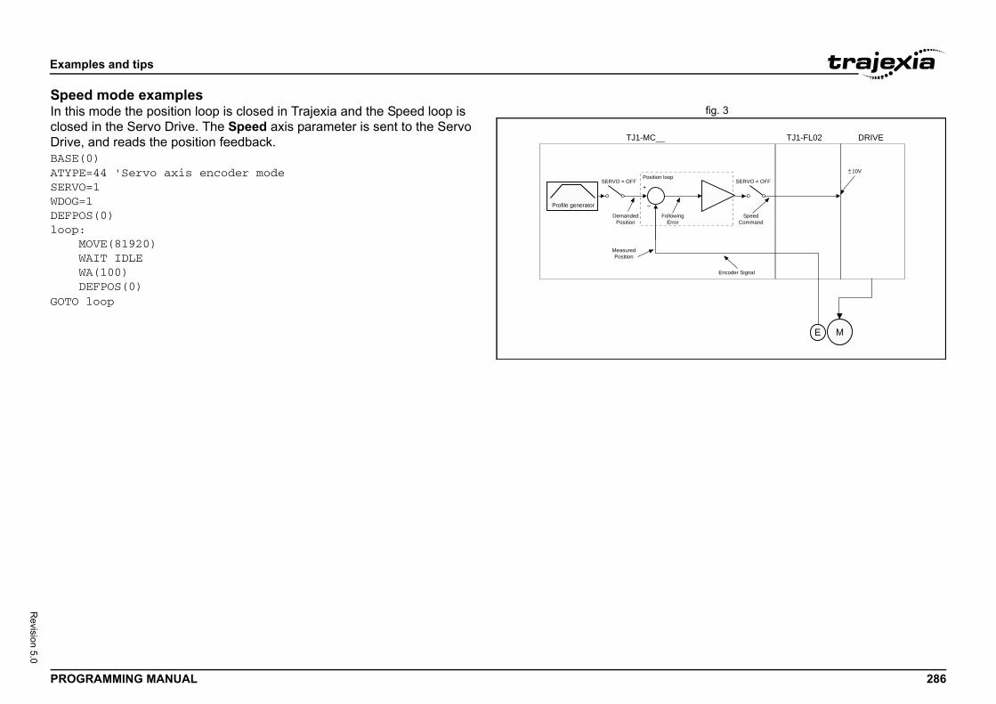
Exam
PROG 286
Revision 5.0
Speefig. 3In this
closeDriveBASE(ATYPESERVOWDOG=DEFPOloop: M W W DGOTO
wingor
SpeedCommand
Encoder Signal
10V+_
TJ1-FL02 DRIVE
SERVO = OFF
ME
ples and tips
RAMMING MANUAL
d mode examples mode the position loop is closed in Trajexia and the Speed loop is
d in the Servo Drive. The Speed axis parameter is sent to the Servo , and reads the position feedback. 0)=44 'Servo axis encoder mode=11S(0)
OVE(81920)AIT IDLEA(100)EFPOS(0)loop
FolloErr
DemandedPosition
MeasuredPosition
Position loop
+
_
TJ1-MC__
SERVO = OFF
Profile generator
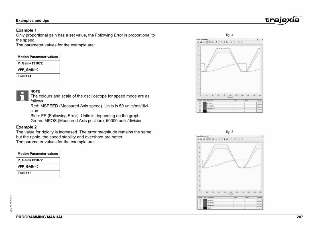
Exam
PROG 287
Revision 5.0
Examfig. 4Only
the spThe p/i
Examfig. 5The v
but thThe p/i
Motio
P_Ga
VFF_
Fn00
Motio
P_Ga
VFF_
Fn00
ples and tips
RAMMING MANUAL
ple 1proportional gain has a set value, the Following Error is proportional to eed.arameter values for the example are:
ple 2alue for rigidity is increased. The error magnitude remains the same e ripple, the speed stability and overshoot are better.arameter values for the example are:
n Parameter values
in=131072
GAIN=0
1=4
NOTEThe colours and scale of the oscilloscope for speed mode are as follows: Red: MSPEED (Measured Axis speed). Units is 50 units/ms/divi-sionBlue: FE (Following Error). Units is depending on the graphGreen: MPOS (Measured Axis position). 50000 units/division
n Parameter values
in=131072
GAIN=0
1=6
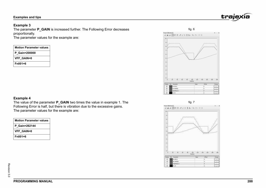
Exam
PROG 288
Revision 5.0
Examfig. 6The p
propoThe p/i
Examfig. 7The v
FollowThe p/i
Motio
P_Ga
VFF_
Fn00
Motio
P_Ga
VFF_
Fn00
ples and tips
RAMMING MANUAL
ple 3arameter P_GAIN is increased further. The Following Error decreases rtionally.arameter values for the example are:
ple 4alue of the parameter P_GAIN two times the value in example 1. The ing Error is half, but there is vibration due to the excessive gains.
arameter values for the example are:
n Parameter values
in=200000
GAIN=0
1=6
n Parameter values
in=262144
GAIN=0
1=6
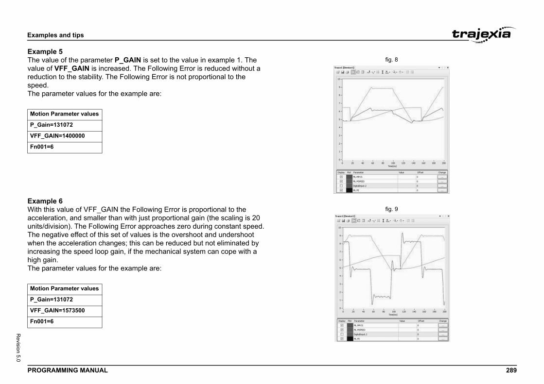
Exam
PROG 289
Revision 5.0
Examfig. 8The v
valuereducspeedThe p/i
Examfig. 9With
accelunits/The nwhenincreahigh gThe p/i
Motio
P_Ga
VFF_
Fn00
Motio
P_Ga
VFF_
Fn00
ples and tips
RAMMING MANUAL
ple 5alue of the parameter P_GAIN is set to the value in example 1. The of VFF_GAIN is increased. The Following Error is reduced without a tion to the stability. The Following Error is not proportional to the .arameter values for the example are:
ple 6this value of VFF_GAIN the Following Error is proportional to the eration, and smaller than with just proportional gain (the scaling is 20 division). The Following Error approaches zero during constant speed. egative effect of this set of values is the overshoot and undershoot the acceleration changes; this can be reduced but not eliminated by sing the speed loop gain, if the mechanical system can cope with a ain.arameter values for the example are:
n Parameter values
in=131072
GAIN=1400000
1=6
n Parameter values
in=131072
GAIN=1573500
1=6
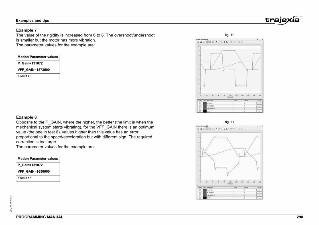
Exam
PROG 290
Revision 5.0
Examfig. 10The v
is smThe p/i
Examfig. 11Oppo
mechvaluepropocorreThe p/i
Motio
P_Ga
VFF_
Fn00
Motio
P_Ga
VFF_
Fn00
ples and tips
RAMMING MANUAL
ple 7alue of the rigidity is increased from 6 to 8. The overshoot/undershoot aller but the motor has more vibration.arameter values for the example are:
ple 8site to the P_GAIN, where the higher, the better (the limit is when the anical system starts vibrating), for the VFF_GAIN there is an optimum (the one in test 6), values higher than this value has an error rtional to the speed/acceleration but with different sign. The required
ction is too large.arameter values for the example are:
n Parameter values
in=131072
GAIN=1573500
1=8
n Parameter values
in=131072
GAIN=1650000
1=6
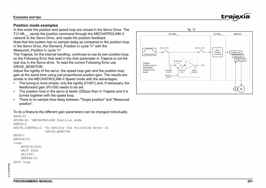
Exam
PROG 291
Revision 5.0
Posifig. 12In this
TJ1-MnetwoNote in theMeasThe Tso thereal oDRIVAdjusgain asimila• T
fe• T
tu• T
p
To doBASE(ATYPESERVODRIVE WDOG=DEFPOloop: M W W DGOTO
ME
TJ1-ML__ SERVO
SERVO = OFFML-II
Positioncommand
oop
ollowingerror
Speedcommand
Position Loop
Speed Loop
Torque Loop
ples and tips
RAMMING MANUAL
tion mode examples mode the position and speed loop are closed in the Servo Drive. The L__ sends the position command through the MECHATROLINK-II rk to the Servo Drive, and reads the position feedback.
that this system has no sample delay as compared to the position loop Servo Drive, the Demand_Position in cycle "n" with the ured_Position in cycle "n".rajexia, for the internal handling, continues to use its own position loop, Following Error that read in the Axis parameter in Trajexia is not the ne in the Servo-drive. To read the correct Following Error use E_MONITOR.t the rigidity of the servo, the speed loop gain and the position loop t the same time using just proportional position gain. The results are r to the MECHATROLINK-II Speed mode with the advantages:he tuning is more simple, only the rigidity (Fn001) and, if necessary, the edforward gain (Pn109) needs to be set.he position loop in the servo is faster (250µs) than in Trajexia and it is rned together with the speed loop.here is no sample time delay between "Target position" and "Measured osition”.
a finetune the different gain parameters can be changed individually.0)=41 'MECHATROLINK Position mode=1_CONTROL=2 'To monitor the Following Error in 'DRIVE_MONITOR1S(0)
OVE(81920)AIT IDLEA(100)EFPOS(0)loop
Profile generator
TJ1-MC__
+
_
SERVO = OFF
Trajexia Position Loop is deactivated(Gains are not used!)
Demandedposition
Measuredposition
Position l
F
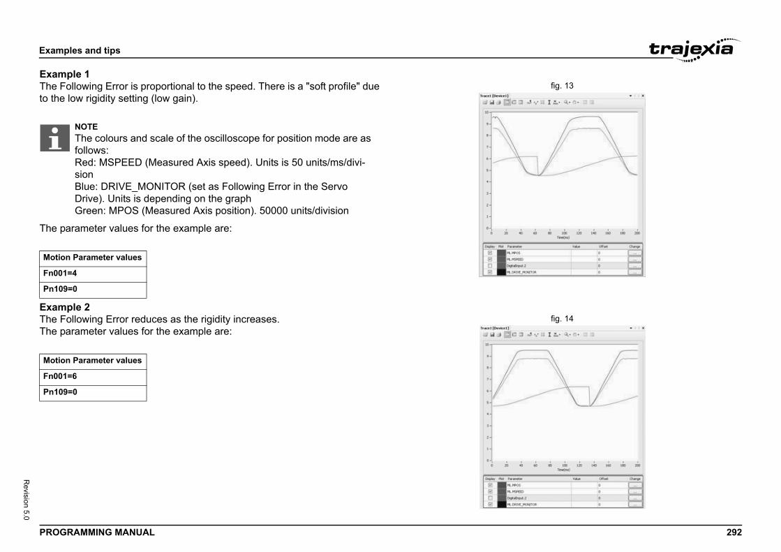
Exam
PROG 292
Revision 5.0
Examfig. 13The F
to the
The p/i
Examfig. 14The F
The p/i
Motio
Fn00
Pn10
Motio
Fn00
Pn10
ples and tips
RAMMING MANUAL
ple 1ollowing Error is proportional to the speed. There is a "soft profile" due low rigidity setting (low gain).
arameter values for the example are:
ple 2ollowing Error reduces as the rigidity increases.arameter values for the example are:
NOTEThe colours and scale of the oscilloscope for position mode are as follows: Red: MSPEED (Measured Axis speed). Units is 50 units/ms/divi-sionBlue: DRIVE_MONITOR (set as Following Error in the Servo Drive). Units is depending on the graphGreen: MPOS (Measured Axis position). 50000 units/division
n Parameter values
1=4
9=0
n Parameter values
1=6
9=0
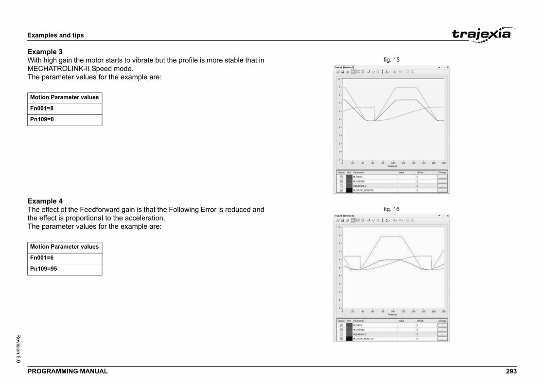
Exam
PROG 293
Revision 5.0
Examfig. 15With
MECHThe p/i
Examfig. 16The e
the eThe p/i
Motio
Fn00
Pn10
Motio
Fn00
Pn10
ples and tips
RAMMING MANUAL
ple 3high gain the motor starts to vibrate but the profile is more stable that in
ATROLINK-II Speed mode.arameter values for the example are:
ple 4ffect of the Feedforward gain is that the Following Error is reduced and
ffect is proportional to the acceleration.arameter values for the example are:
n Parameter values
1=8
9=0
n Parameter values
1=6
9=95
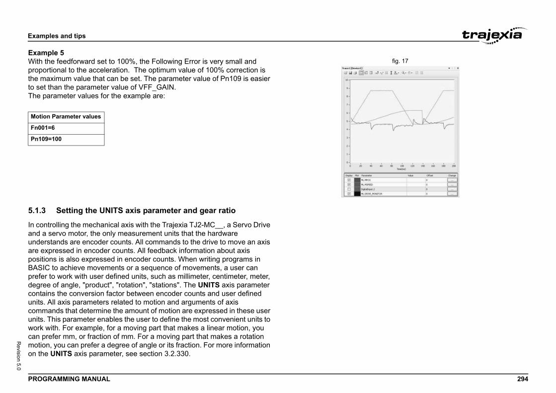
Exam
PROG 294
Revision 5.0
Examfig. 17With
propothe mto setThe p/i
5.1.3
In conand aunderare epositiBASIprefedegrecontaunits.communits.work can pmotioon th
Motio
Fn00
Pn10
ples and tips
RAMMING MANUAL
ple 5the feedforward set to 100%, the Following Error is very small and rtional to the acceleration. The optimum value of 100% correction is aximum value that can be set. The parameter value of Pn109 is easier than the parameter value of VFF_GAIN.arameter values for the example are:
Setting the UNITS axis parameter and gear ratio
trolling the mechanical axis with the Trajexia TJ2-MC__, a Servo Drive servo motor, the only measurement units that the hardware stands are encoder counts. All commands to the drive to move an axis
xpressed in encoder counts. All feedback information about axis ons is also expressed in encoder counts. When writing programs in C to achieve movements or a sequence of movements, a user can r to work with user defined units, such as millimeter, centimeter, meter, e of angle, "product", "rotation", "stations". The UNITS axis parameter ins the conversion factor between encoder counts and user defined All axis parameters related to motion and arguments of axis ands that determine the amount of motion are expressed in these user
This parameter enables the user to define the most convenient units to with. For example, for a moving part that makes a linear motion, you refer mm, or fraction of mm. For a moving part that makes a rotation n, you can prefer a degree of angle or its fraction. For more information e UNITS axis parameter, see section 3.2.330.
n Parameter values
1=6
9=100
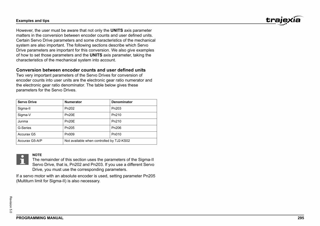
Exam
PROG 295
Revision 5.0
HowematteCertasysteDriveof hochara
ConvTwo vencodthe elparam/i
If a se(Multi
Servo
Sigma
Sigma
Junm
G-Se
Accur
Accur
ples and tips
RAMMING MANUAL
ver, the user must be aware that not only the UNITS axis parameter rs in the conversion between encoder counts and user defined units. in Servo Drive parameters and some characteristics of the mechanical m are also important. The following sections describe which Servo parameters are important for this conversion. We also give examples w to set those parameters and the UNITS axis parameter, taking the cteristics of the mechanical system into account.
ersion between encoder counts and user defined unitsery important parameters of the Servo Drives for conversion of er counts into user units are the electronic gear ratio numerator and ectronic gear ratio denominator. The table below gives these eters for the Servo Drives.
rvo motor with an absolute encoder is used, setting parameter Pn205 turn limit for Sigma-II) is also necessary.
Drive Numerator Denominator
-II Pn202 Pn203
-V Pn20E Pn210
a Pn20E Pn210
ries Pn205 Pn206
ax G5 Pn009 Pn010
ax G5-A/P Not available when controlled by TJ2-KS02
NOTEThe remainder of this section uses the parameters of the Sigma-II Servo Drive, that is, Pn202 and Pn203. If you use a different Servo Drive, you must use the corresponding parameters.
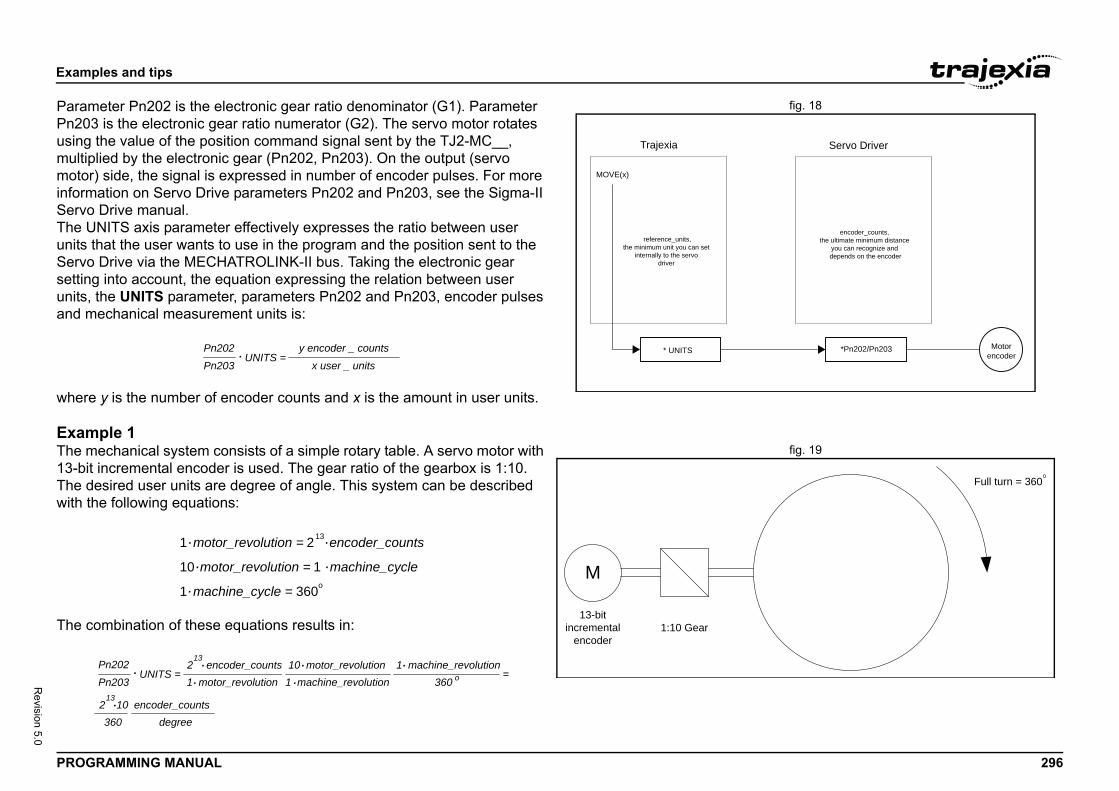
Exam
PROG 296
Revision 5.0
fig. 18ParamPn20usingmultipmotorinformServoThe Uunits Servosettinunits,and m
where
Examfig. 19The m
13-bitThe dwith t
The c
Servo Driver
*Pn202/Pn203
encoder_counts, the ultimate minimum distance
you can recognize and depends on the encoder
Motorencoder
Full turn = 360
ples and tips
RAMMING MANUAL
eter Pn202 is the electronic gear ratio denominator (G1). Parameter 3 is the electronic gear ratio numerator (G2). The servo motor rotates the value of the position command signal sent by the TJ2-MC__, lied by the electronic gear (Pn202, Pn203). On the output (servo ) side, the signal is expressed in number of encoder pulses. For more ation on Servo Drive parameters Pn202 and Pn203, see the Sigma-II Drive manual.NITS axis parameter effectively expresses the ratio between user
that the user wants to use in the program and the position sent to the Drive via the MECHATROLINK-II bus. Taking the electronic gear g into account, the equation expressing the relation between user the UNITS parameter, parameters Pn202 and Pn203, encoder pulses echanical measurement units is:
y is the number of encoder counts and x is the amount in user units.
ple 1echanical system consists of a simple rotary table. A servo motor with
incremental encoder is used. The gear ratio of the gearbox is 1:10.esired user units are degree of angle. This system can be described he following equations:
ombination of these equations results in:
Trajexia
MOVE(x)
* UNITS
reference_units,the minimum unit you can set
internally to the servo driver
Pn202 y·encoder _ counts
Pn203 x·user _ unitsUNITS =.
1:10 Gear
M
13-bitincremental
encoder
1 motor_revolution = 213 encoder_counts
10 motor_revolution = 1 machine_cycle
1 machine_cycle = 360o
.
.
.
.
.
Pn202
Pn203UNITS = =. 2
13
13
encoder_counts1 motor_revolution 1 machine_revolution
10 motor_revolution360
1 machine_revolutiono
3602 10
degreeencoder_counts
..
.. .
.
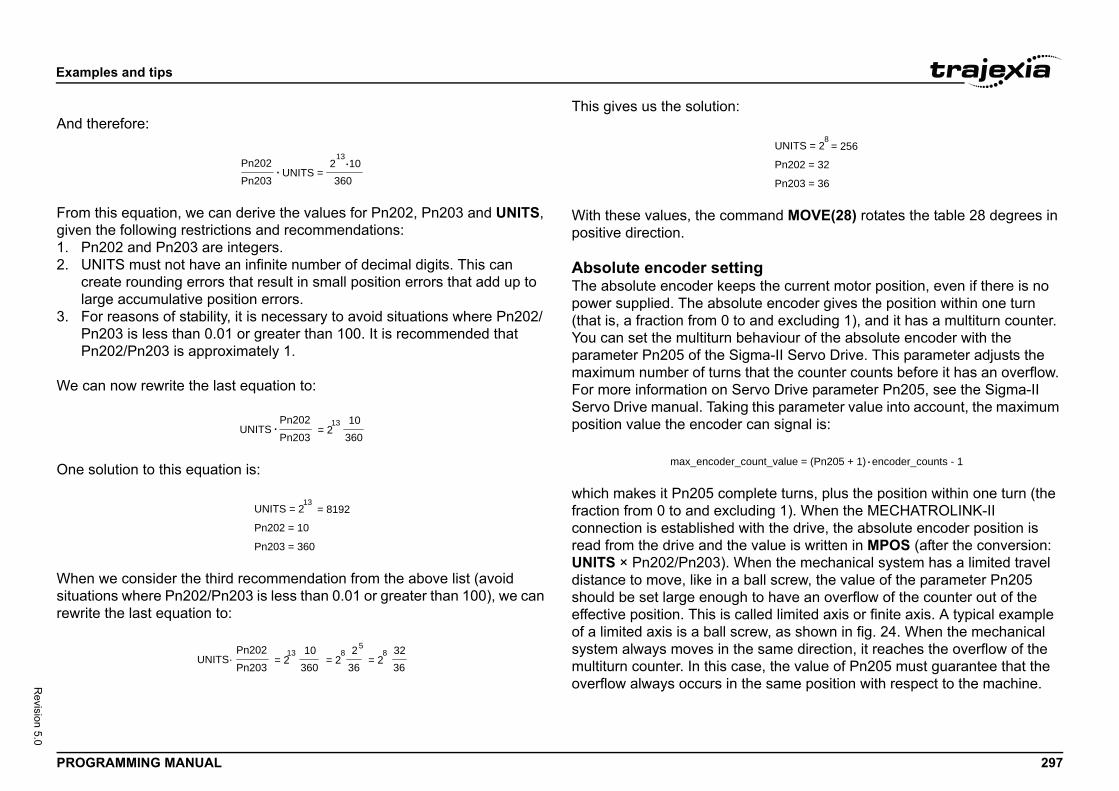
Exam
PROG 297
Revision 5.0
And t
Fromgiven1. P2. U
crla
3. FPP
We c
One s
Whensituatrewrit
and MOVE(28) rotates the table 28 degrees in
the current motor position, even if there is no encoder gives the position within one turn
nd excluding 1), and it has a multiturn counter. aviour of the absolute encoder with the a-II Servo Drive. This parameter adjusts the
at the counter counts before it has an overflow. o Drive parameter Pn205, see the Sigma-II
his parameter value into account, the maximum n signal is:
ete turns, plus the position within one turn (the ing 1). When the MECHATROLINK-II h the drive, the absolute encoder position is alue is written in MPOS (after the conversion: en the mechanical system has a limited travel ll screw, the value of the parameter Pn205 o have an overflow of the counter out of the ed limited axis or finite axis. A typical example w, as shown in fig. 24. When the mechanical same direction, it reaches the overflow of the , the value of Pn205 must guarantee that the same position with respect to the machine.
Pn202 = 32
Pn203 = 36
UNITS = 2 = 2568
nt_value = (Pn205 + 1) encoder_counts - 1.
ples and tips
RAMMING MANUAL
herefore:
this equation, we can derive the values for Pn202, Pn203 and UNITS, the following restrictions and recommendations:n202 and Pn203 are integers.NITS must not have an infinite number of decimal digits. This can eate rounding errors that result in small position errors that add up to rge accumulative position errors.or reasons of stability, it is necessary to avoid situations where Pn202/n203 is less than 0.01 or greater than 100. It is recommended that n202/Pn203 is approximately 1.
an now rewrite the last equation to:
olution to this equation is:
we consider the third recommendation from the above list (avoid ions where Pn202/Pn203 is less than 0.01 or greater than 100), we can e the last equation to:
This gives us the solution:
With these values, the commpositive direction.
Absolute encoder settingThe absolute encoder keepspower supplied. The absolute(that is, a fraction from 0 to aYou can set the multiturn behparameter Pn205 of the Sigmmaximum number of turns thFor more information on ServServo Drive manual. Taking tposition value the encoder ca
which makes it Pn205 complfraction from 0 to and excludconnection is established witread from the drive and the vUNITS × Pn202/Pn203). Whdistance to move, like in a bashould be set large enough teffective position. This is callof a limited axis is a ball scresystem always moves in the multiturn counter. In this caseoverflow always occurs in the
Pn202Pn203
UNITS =. 213
10360
.
Pn202Pn203
UNITS10
360= 2
13.
Pn202 = 10
Pn203 = 360
UNITS = 2 = 819213
Pn202Pn203
UNITS·10
360= 2
13 236
= 28 32
36= 2
85
max_encoder_cou
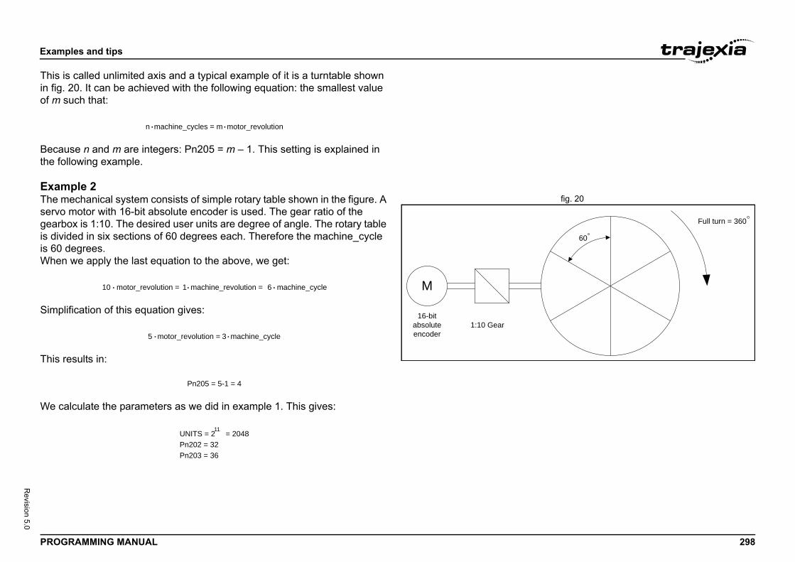
Exam
PROG 298
Revision 5.0
This iin fig.of m s
Becathe fo
Examfig. 20The m
servogearbis divis 60 When
Simp
This r
We c
Full turn = 360
60
ples and tips
RAMMING MANUAL
s called unlimited axis and a typical example of it is a turntable shown 20. It can be achieved with the following equation: the smallest value uch that:
use n and m are integers: Pn205 = m – 1. This setting is explained in llowing example.
ple 2echanical system consists of simple rotary table shown in the figure. A
motor with 16-bit absolute encoder is used. The gear ratio of the ox is 1:10. The desired user units are degree of angle. The rotary table
ided in six sections of 60 degrees each. Therefore the machine_cycle degrees. we apply the last equation to the above, we get:
lification of this equation gives:
esults in:
alculate the parameters as we did in example 1. This gives:
n machine_cycles = m motor_revolution. .
1:10 Gear
M
16-bitabsoluteencoder
10 motor_revolution = 1 machine_revolution = 6 machine_cycle. . .
5 motor_revolution = 3 machine_cycle. .
Pn205 = 5-1 = 4
UNITS = 2 = 204811
Pn202 = 32Pn203 = 36
Exam
PROG 299
Revision 5.0
To gumust REP_table DPOS
olute encoder position is read from the motor using the following conversion:
eater than 224, MPOS can have incorrect val-o avoid this problem, add the program code ODER/UNITS after all UNITS initializations.
e absolute position is always correct, you t
bvious for the high-resolution encoders of the
POS = abs_position_encoderUNITS
1Pn202Pn203. .
5 + 1)Pn202Pn203. . encoder_counts < 224
Pn205 + 1) .. encoder_resolution < 232
05 + 1) .Pn202Pn203.encoder_resolution < 232
ples and tips
RAMMING MANUAL
arantee the correct overflow both in Trajexia and in the Servo Drive, we set two additional axis parameters: REP_DIST = 60, and OPTION = 1. With these settings, the command MOVE(35) rotates the 35 degrees in positive direction. The range of possible MPOS and values is from 0 degrees to 60 degrees.
CAUTIONYou must initialize the absolute encoder before you use it for the first time, when the battery is lost during power off and when the multiturn limit setting in the parameter Pn205 is changed. The ini-tialization can be done on the display of the Servo Drive or with the software tool. For more detail on initialising absolute encoder, please see the Sigma-II Servo Drive manual.
CAUTIONIt is possible to reset the multiturn counter, but it is not possible to reset the position within one turn (the fraction from 0 to and exclud-ing 1). To adjust zero offset, use the parameter Pn808. For more details see the NS115 MECHATROLINK-II Interface Unit manual.
CAUTIONAt power up, the absand written to MPOS• For MPOS:
• This is correct if
• If this value is grues at start-up. TDEFPOS = ENC
CAUTIONTo make sure that thmust make sure tha
and that
Note that this is not oSigma-V motors.
Absolute_M
(Pn20
(
(Pn2
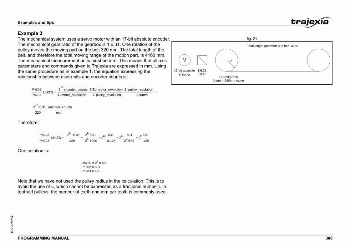
Exam
PROG 300
Revision 5.0
Examfig. 21The m
The mpulleybelt, aThe mparamthe sarelatio
There
One s
Note avoidtoothe
)ove
Total length (perimeter) of belt: 4160
ples and tips
RAMMING MANUAL
ple 3echanical system uses a servo motor with an 17-bit absolute encoder. echanical gear ratio of the gearbox is 1:6.31. One rotation of the moves the moving part on the belt 320 mm. The total length of the nd therefore the total moving range of the motion part, is 4160 mm.echanical measurement units must be mm. This means that all axis eters and commands given to Trajexia are expressed in mm. Using me procedure as in example 1, the equation expressing the nship between user units and encoder counts is:
fore:
olution is:
that we have not used the pulley radius in the calculation. This is to the use of π, which cannot be expressed as a fractional number). In d pulleys, the number of teeth and mm per tooth is commonly used.
1:6.31Gear
r = 320/(2*PI1 turn = 320mm m
M r
17-bit absoluteencoder
Pn202Pn203
UNITS =2
17 encoder_counts
1 motor_revolution 1 pulley_revolution6.31 motor_revolution
320mm1 pulley_revolution
3202 6.31
mmencoder_counts
=
.17
..
. ..
Pn202
Pn203UNITS =
2
320
17 6.31 2
1000
17631
=25 8.125
631= 212 631
= 212
12523631
= 29
125
.
.
9UNITS = 2 = 512Pn202 = 631Pn203 = 125
Exam
PROG 301
Revision 5.0
The c
The sPn20In addpart, REP_movinDPOS
m
m
=
m
ples and tips
RAMMING MANUAL
alculation of the multiturn limit setting is:
mallest integer m for which this equation is valid is 8203. This results in 5 = 8202.ition, to limit the motion units range to the moving range of the motion
the following axis parameters must be set: REP_DIST = 4260, and OPTION = 1. With these settings, executing MOVE(38) moves the g part 38 mm in forward direction. The range of possible MPOS and values is 0 mm to 4160 mm.
motor_revolution = n machine_cycle
motor_revolution = n machine_cycle4160 pulley_revolution
320 machine_cycle= n 13 pulley_revolution
n 136 31 motor_revolution
1 pulley_revolution= n 82.03 pulley_revolution
= n 82.03
. .
. . ....
. . ..
.
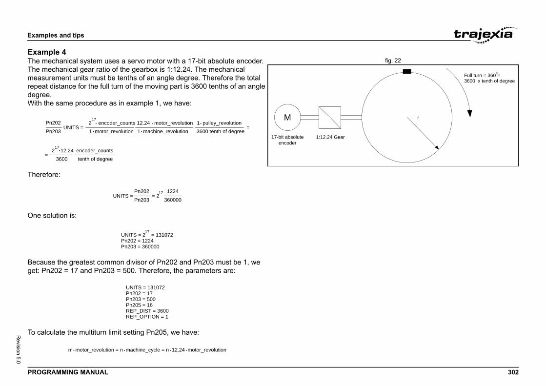
Exam
PROG 302
Revision 5.0
Examfig. 22The m
The mmeasrepeadegreWith
There
One s
Becaget: P
To ca
r
Full turn = 360 =3600 x tenth of degree
ples and tips
RAMMING MANUAL
ple 4echanical system uses a servo motor with a 17-bit absolute encoder. echanical gear ratio of the gearbox is 1:12.24. The mechanical
urement units must be tenths of an angle degree. Therefore the total t distance for the full turn of the moving part is 3600 tenths of an angle e.
the same procedure as in example 1, we have:
fore:
olution is:
use the greatest common divisor of Pn202 and Pn203 must be 1, we n202 = 17 and Pn203 = 500. Therefore, the parameters are:
lculate the multiturn limit setting Pn205, we have:
1:12.24 Gear
M
17-bit absoluteencoder
Pn202Pn203
UNITS =2
17 encoder_counts
1 motor_revolution 1 machine_revolution12.24 motor_revolution
3600 tenth of degree1 pulley_revolution
36002 12.24 encoder_counts
=
tenth of degree=
..
.. .
.17
Pn202Pn203
UNITS = = 21224
36000017
UNITS = 2 = 131072Pn202 = 1224Pn203 = 360000
17
UNITS = 131072Pn202 = 17Pn203 = 500Pn205 = 16REP_DIST = 3600REP_OPTION = 1
m motor_revolution = n machine_cycle = n 12.24 motor_revolution. . ..
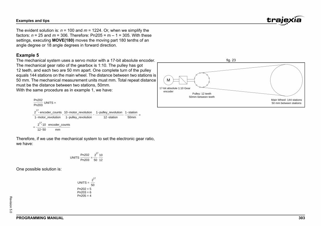
Exam
PROG 303
Revision 5.0
The efactorsettinangle
Examfig. 23The m
The m12 teeequal50 mmmust With
Therewe ha
One p
Main Wheel: 144 stations50 mm between stations
ples and tips
RAMMING MANUAL
vident solution is: n = 100 and m = 1224. Or, when we simplify the s: n = 25 and m = 306. Therefore: Pn205 = m – 1 = 305. With these gs, executing MOVE(180) moves the moving part 180 tenths of an degree or 18 angle degrees in forward direction.
ple 5echanical system uses a servo motor with a 17-bit absolute encoder. echanical gear ratio of the gearbox is 1:10. The pulley has got th, and each two are 50 mm apart. One complete turn of the pulley
s 144 stations on the main wheel. The distance between two stations is . The mechanical measurement units must mm. Total repeat distance
be the distance between two stations, 50mm.the same procedure as in example 1, we have:
fore, if we use the mechanical system to set the electronic gear ratio, ve:
ossible solution is:
M
1:10 Gear17-bit absoluteencoder
Pulley: 12 teeth50mm between teeth
Pn202Pn203
UNITS =
217
encoder_counts1 motor_revolution 1 pulley_revolution
10 motor_revolution12 station
1 pulley_revolution
12 502
1710 encoder_counts
mm=
50mm1 station
=..
..
.. .
.
.
..
Pn202Pn203
UNITS502
1710
=12
Pn202 = 5Pn203 = 6Pn205 = 4
UNITS =50217
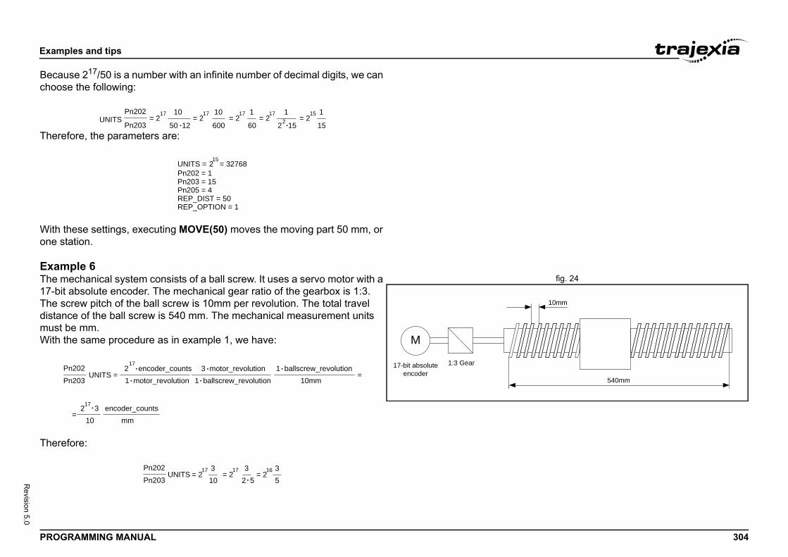
Exam
PROG 304
Revision 5.0
Becachoos
There
With one s
Examfig. 24The m
17-bitThe sdistanmust With
There
10mm
540mm
ples and tips
RAMMING MANUAL
use 217/50 is a number with an infinite number of decimal digits, we can e the following:
fore, the parameters are:
these settings, executing MOVE(50) moves the moving part 50 mm, or tation.
ple 6echanical system consists of a ball screw. It uses a servo motor with a
absolute encoder. The mechanical gear ratio of the gearbox is 1:3. crew pitch of the ball screw is 10mm per revolution. The total travel ce of the ball screw is 540 mm. The mechanical measurement units be mm.the same procedure as in example 1, we have:
fore:
Pn202
Pn203UNITS
50 12
1017= 2
17= 2
600
10 17= 2
60
1 15= 2
122 15 15
117= 2
..
UNITS = 2 = 3276815
Pn202 = 1Pn203 = 15Pn205 = 4REP_DIST = 50REP_OPTION = 1
M
1:3 Gear17-bit absoluteencoder
Pn202Pn203
UNITS =2
17 encoder_counts
1 motor_revolution 1 ballscrew_revolution3 motor_revolution
10mm1 ballscrew_revolution
10217 3 encoder_counts
=
mm=
..
. ..
.
Pn202Pn203
UNITS17
= 2103 17
= 22 53 16
= 253
.
Exam
PROG 305
Revision 5.0
One s
The cin thisenougof theto setenougsolutiWith forwa
ples and tips
RAMMING MANUAL
olution is:
alculation of the multiturn limit setting parameter Pn205 is not needed case because the ball screw is a system with a fixed (limited) axis. It is h to set this value large enough to have the overflow of the counter out
effective position. Also, because of the axis is finite, it is not important the REP_OPTION parameter, because REP_DIST must be set large h so it is outside of the maximum effective position (540 mm). One
on is: REP_DIST = 1000 and REP_OPTION = 0.these setting, executing MOVE(17) moves the ball screw 17 mm in rd direction.
UNITS = 2 = 6553616
Pn202 = 3Pn203 = 5
Exam
PROG 306
Revision 5.0
5.1.4
The TdigitaThe d• D
Tth
• DTaTththw
• DTthucoU
• DTaWua
All ou
The d• D
TaT
en a 24 VDC signal is applied to them. When n their current status. Use the command IN to
e inputs only. They do not physically exist on an read them. You use them mostly in BASIC ome control sequences that require inputs hysical. Use the command IN to read these
lly present only if additional digital I/O units are __ via MECHATROLINK-II or EtherCAT. If you hysically exist (the I/O units are not . Use the command IN to read these inputs.
ontroller. They are not accessed per axis.
ples and tips
RAMMING MANUAL
Mapping Servo Drive inputs and outputs
rajexia controller has got a digital I/O space that consists of 1024 l inputs and 1024 digital outputs.igital outputs range has four parts:igital outputs 0 - 7.hese outputs do not physically exist on the TJ2-MC__. If you write ese outputs, nothing happens. If you read these outputs, they return 0.igital outputs 8 - 15.hese outputs physically exist on the TJ2-MC__. You can physically ccess them on the 28-pin screwless connector on the front side of the J2-MC__ (see the Hardware Reference Manual for details). If you write ese outputs, they become active and give a 24 VDC signal. If you read ese outputs, they return their current status. Use the command OP to rite and read these outputs.igital outputs 16 - 31.hese outputs are software outputs only. They do not physically exist on e TJ2-MC__, but you can write them and read their correct status. You se these outputs mostly in BASIC programs to accomplish some ntrol sequences that require outputs which do not need to be physical.
se the command OP to write and read these outputs.igital outputs 32 - 1023.hese outputs are physically present only if additional digital I/O units re connected to the TJ2-MC__ via MECHATROLINK-II or EtherCAT. riting and reading them if they do not physically exist (when the I/O
nits are not connected) has no effect. Use the command OP to write nd read these outputs.
tputs are unique to the controller. They are not accessed per axis.
igital input range has three parts:igital inputs 0 - 15.hese inputs physically exist on the TJ2-MC__. You can physically ccess them on the 28-pin screwless connector on the front side of the J2-MC__ (see the Hardware Reference Manual for details). These
inputs are active (ON) whyou read them, they returread these inputs.
• Digital inputs 16 - 31.These inputs are softwarthe TJ2-MC__, but you cprograms to accomplish swhich do not need to be pinputs.
• Digital inputs 32 - 255.These inputs are physicaconnected to the TJ2-MCread them if they do not pconnected), they return 0
All inputs are unique to the c
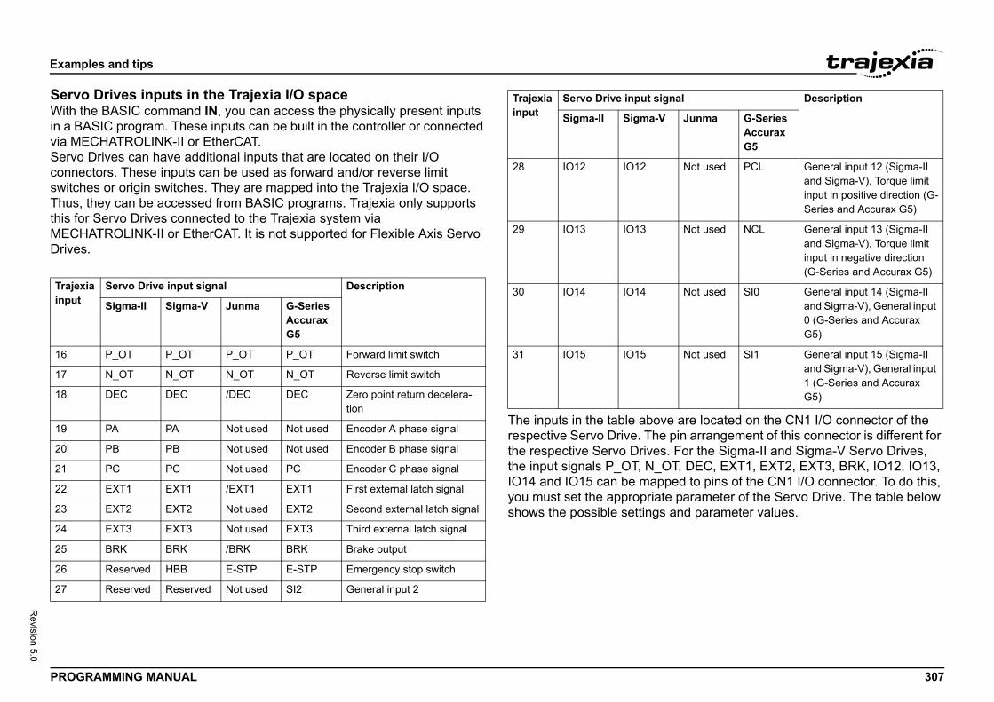
Exam
PROG 307
Revision 5.0
ServWith in a Bvia MServoconneswitchThus,this foMECHDrive/i
are located on the CN1 I/O connector of the in arrangement of this connector is different for For the Sigma-II and Sigma-V Servo Drives, T, DEC, EXT1, EXT2, EXT3, BRK, IO12, IO13, ed to pins of the CN1 I/O connector. To do this, parameter of the Servo Drive. The table below nd parameter values.
Trajeinput
16
17
18
19
20
21
22
23
24
25
26
27
Not used PCL General input 12 (Sigma-II and Sigma-V), Torque limit input in positive direction (G-Series and Accurax G5)
Not used NCL General input 13 (Sigma-II and Sigma-V), Torque limit input in negative direction (G-Series and Accurax G5)
Not used SI0 General input 14 (Sigma-II and Sigma-V), General input 0 (G-Series and Accurax G5)
Not used SI1 General input 15 (Sigma-II and Sigma-V), General input 1 (G-Series and Accurax G5)
al Description
Junma G-Series Accurax G5
ples and tips
RAMMING MANUAL
o Drives inputs in the Trajexia I/O spacethe BASIC command IN, you can access the physically present inputs ASIC program. These inputs can be built in the controller or connected ECHATROLINK-II or EtherCAT. Drives can have additional inputs that are located on their I/O ctors. These inputs can be used as forward and/or reverse limit es or origin switches. They are mapped into the Trajexia I/O space.
they can be accessed from BASIC programs. Trajexia only supports r Servo Drives connected to the Trajexia system via ATROLINK-II or EtherCAT. It is not supported for Flexible Axis Servo
s.
The inputs in the table aboverespective Servo Drive. The pthe respective Servo Drives. the input signals P_OT, N_OIO14 and IO15 can be mappyou must set the appropriateshows the possible settings a
xia Servo Drive input signal Description
Sigma-II Sigma-V Junma G-Series Accurax G5
P_OT P_OT P_OT P_OT Forward limit switch
N_OT N_OT N_OT N_OT Reverse limit switch
DEC DEC /DEC DEC Zero point return decelera-tion
PA PA Not used Not used Encoder A phase signal
PB PB Not used Not used Encoder B phase signal
PC PC Not used PC Encoder C phase signal
EXT1 EXT1 /EXT1 EXT1 First external latch signal
EXT2 EXT2 Not used EXT2 Second external latch signal
EXT3 EXT3 Not used EXT3 Third external latch signal
BRK BRK /BRK BRK Brake output
Reserved HBB E-STP E-STP Emergency stop switch
Reserved Reserved Not used SI2 General input 2
28 IO12 IO12
29 IO13 IO13
30 IO14 IO14
31 IO15 IO15
Trajexiainput
Servo Drive input sign
Sigma-II Sigma-V
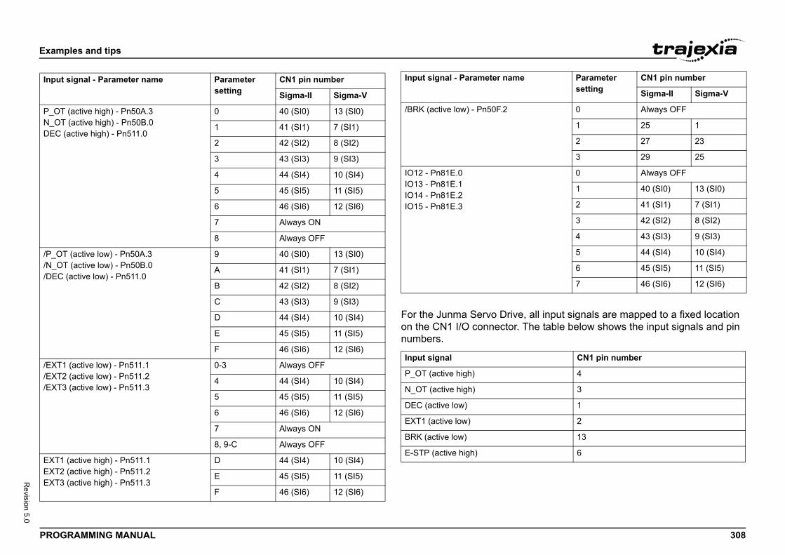
Exam
PROG 308
Revision 5.0
/i
ll input signals are mapped to a fixed location e table below shows the input signals and pin
Input
P_OTN_OTDEC
/P_O/N_O/DEC
/EXT1/EXT2/EXT3
EXT1EXT2EXT3
0 Always OFF
1 25 1
2 27 23
3 29 25
0 Always OFF
1 40 (SI0) 13 (SI0)
2 41 (SI1) 7 (SI1)
3 42 (SI2) 8 (SI2)
4 43 (SI3) 9 (SI3)
5 44 (SI4) 10 (SI4)
6 45 (SI5) 11 (SI5)
7 46 (SI6) 12 (SI6)
CN1 pin number
4
3
1
2
13
6
Parametersetting
CN1 pin number
Sigma-II Sigma-V
ples and tips
RAMMING MANUAL
For the Junma Servo Drive, aon the CN1 I/O connector. Thnumbers.
signal - Parameter name Parametersetting
CN1 pin number
Sigma-II Sigma-V
(active high) - Pn50A.3 (active high) - Pn50B.0
(active high) - Pn511.0
0 40 (SI0) 13 (SI0)
1 41 (SI1) 7 (SI1)
2 42 (SI2) 8 (SI2)
3 43 (SI3) 9 (SI3)
4 44 (SI4) 10 (SI4)
5 45 (SI5) 11 (SI5)
6 46 (SI6) 12 (SI6)
7 Always ON
8 Always OFF
T (active low) - Pn50A.3T (active low) - Pn50B.0 (active low) - Pn511.0
9 40 (SI0) 13 (SI0)
A 41 (SI1) 7 (SI1)
B 42 (SI2) 8 (SI2)
C 43 (SI3) 9 (SI3)
D 44 (SI4) 10 (SI4)
E 45 (SI5) 11 (SI5)
F 46 (SI6) 12 (SI6)
(active low) - Pn511.1 (active low) - Pn511.2 (active low) - Pn511.3
0-3 Always OFF
4 44 (SI4) 10 (SI4)
5 45 (SI5) 11 (SI5)
6 46 (SI6) 12 (SI6)
7 Always ON
8, 9-C Always OFF
(active high) - Pn511.1 (active high) - Pn511.2 (active high) - Pn511.3
D 44 (SI4) 10 (SI4)
E 45 (SI5) 11 (SI5)
F 46 (SI6) 12 (SI6)
/BRK (active low) - Pn50F.2
IO12 - Pn81E.0IO13 - Pn81E.1IO14 - Pn81E.2IO15 - Pn81E.3
Input signal
P_OT (active high)
N_OT (active high)
DEC (active low)
EXT1 (active low)
BRK (active low)
E-STP (active high)
Input signal - Parameter name
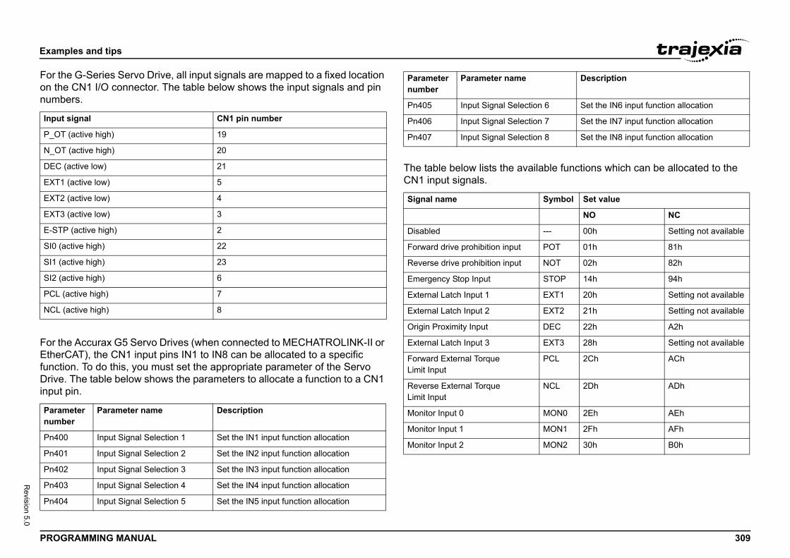
Exam
PROG 309
Revision 5.0
For thon thenumb
For thEtherfunctiDriveinput
ilable functions which can be allocated to the
Input
P_OT
N_OT
DEC
EXT1
EXT2
EXT3
E-ST
SI0 (a
SI1 (a
SI2 (a
PCL (
NCL
Paramnumb
Pn40
Pn40
Pn40
Pn40
Pn40
n 6 Set the IN6 input function allocation
n 7 Set the IN7 input function allocation
n 8 Set the IN8 input function allocation
Symbol Set value
NO NC
--- 00h Setting not available
POT 01h 81h
NOT 02h 82h
STOP 14h 94h
EXT1 20h Setting not available
EXT2 21h Setting not available
DEC 22h A2h
EXT3 28h Setting not available
PCL 2Ch ACh
NCL 2Dh ADh
MON0 2Eh AEh
MON1 2Fh AFh
MON2 30h B0h
Description
ples and tips
RAMMING MANUAL
e G-Series Servo Drive, all input signals are mapped to a fixed location CN1 I/O connector. The table below shows the input signals and pin ers.
e Accurax G5 Servo Drives (when connected to MECHATROLINK-II or CAT), the CN1 input pins IN1 to IN8 can be allocated to a specific on. To do this, you must set the appropriate parameter of the Servo . The table below shows the parameters to allocate a function to a CN1 pin.
The table below lists the avaCN1 input signals.
signal CN1 pin number
(active high) 19
(active high) 20
(active low) 21
(active low) 5
(active low) 4
(active low) 3
P (active high) 2
ctive high) 22
ctive high) 23
ctive high) 6
active high) 7
(active high) 8
eter er
Parameter name Description
0 Input Signal Selection 1 Set the IN1 input function allocation
1 Input Signal Selection 2 Set the IN2 input function allocation
2 Input Signal Selection 3 Set the IN3 input function allocation
3 Input Signal Selection 4 Set the IN4 input function allocation
4 Input Signal Selection 5 Set the IN5 input function allocation
Pn405 Input Signal Selectio
Pn406 Input Signal Selectio
Pn407 Input Signal Selectio
Signal name
Disabled
Forward drive prohibition input
Reverse drive prohibition input
Emergency Stop Input
External Latch Input 1
External Latch Input 2
Origin Proximity Input
External Latch Input 3
Forward External TorqueLimit Input
Reverse External TorqueLimit Input
Monitor Input 0
Monitor Input 1
Monitor Input 2
Parameter number
Parameter name
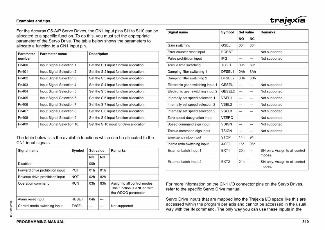
Exam
PROG 310
Revision 5.0
For thallocaparamalloca
The tCN1
CN1 I/O connector pins on the Servo Drives, ive manual.
apped into the Trajexia I/O space like this are per axis and cannot be accessed in the usual he only way you can use these inputs in the
Paramnumb
Pn40
Pn40
Pn40
Pn40
Pn40
Pn40
Pn40
Pn40
Pn40
Pn40
Signa
Disab
Forwa
Reve
Opera
Alarm
Contr
GSEL 06h 86h
ECRST --- --- Not supported
IPG --- --- Not supported
TLSEL 09h 89h
DFSEL1 0Ah 8Ah
DFSEL2 0Bh 8Bh
GESEL1 --- --- Not supported
GESEL2 --- --- Not supported
VSEL1 --- --- Not supported
VSEL2 --- --- Not supported
VSEL3 --- --- Not supported
VZERO --- --- Not supported
VSIGN --- --- Not supported
TSIGN --- --- Not supported
STOP 14h 94h
J-SEL 15h 95h
EXT1 20h --- SI4 only. Assign to all control modes.
EXT2 21h --- SI4 only. Assign to all control modes.
Symbol Set value Remarks
NO NC
ples and tips
RAMMING MANUAL
e Accurax G5-A/P Servo Drives, the CN1 input pins SI1 to SI10 can be ted to a specific function. To do this, you must set the appropriate eter of the Servo Drive. The table below shows the parameters to te a function to a CN1 input pin.
able below lists the available functions which can be allocated to the input signals.
For more information on the refer to the specific Servo Dr
Servo Drive inputs that are maccessed within the programway with the IN command. T
eter er
Parameter name Description
0 Input Signal Selection 1 Set the SI1 input function allocation.
1 Input Signal Selection 2 Set the SI2 input function allocation.
2 Input Signal Selection 3 Set the SI3 input function allocation.
3 Input Signal Selection 4 Set the SI4 input function allocation.
4 Input Signal Selection 5 Set the SI5 input function allocation.
5 Input Signal Selection 6 Set the SI6 input function allocation.
6 Input Signal Selection 7 Set the SI7 input function allocation.
7 Input Signal Selection 8 Set the SI8 input function allocation.
8 Input Signal Selection 9 Set the SI9 input function allocation.
9 Input Signal Selection 10 Set the SI10 input function allocation.
l name Symbol Set value Remarks
NO NC
led --- 00h ---
rd drive prohibition input POT 01h 81h
rse drive prohibition input NOT 02h 82h
tion command RUN 03h 83h Assign to all control modes. This function is ANDed with the WDOG parameter.
reset input RESET 04h ---
ol mode switching input TVSEL --- --- Not supported
Gain switching
Error counter reset input
Pulse prohibition input
Torque limit switching
Damping filter switching 1
Damping filter switching 2
Electronic gear switching input 1
Electronic gear switching input 2
Internally set speed selection 1
Internally set speed selection 2
Internally set speed selection 2
Zero speed designation input
Speed command sign input
Torque command sign input
Emergency stop input
Inertia ratio switching input
External Latch Input 1
External Latch Input 2
Signal name
Exam
PROG 311
Revision 5.0
progrFWDdepen
Exam0 andto CNthe Jufor ax
REV_REV_
Note valueof theCN1-that tcontrotime. commcontrothan Scommcontroaccesexam
ples and tips
RAMMING MANUAL
am is to assign them to the axis parameters DATUM_IN, FHOLD_IN, _IN and REV_IN. The inputs of the axis Servo Drive are used, ding on the axis of which the parameters are set.
ple: We have a Sigma-II and a Junma drive assigned to controller axes 3. For the Sigma-II drive, we want to use input signal EXT1 (mapped 1-44 if Pn511.2 is set to 4) to serve as reverse limit input for axis 0. For nma drive, we want to use input signal EXT1 (CN1-2) as reverse limit is 3. We can do this with these commands:
IN AXIS(0) = 22IN AXIS(3) = 22
that even though REV_IN parameters for both axes have the same , the real inputs used are not the same. For axis 0 the input on CN1-44 Sigma-II drive (assigned to axis 0) is used, but for axis 3 the input on 41 of the Junma drive (assigned to axis 3) is used. Therefore we say hose inputs are accessed per axis, they are not unique for the whole ller. In general, these two inputs have a different status at the same
Also note that neither of these two inputs can be accessed using the and IN. For example the command IN(22) returns the status of ller software input 22 (unique for all axes), which has a different status ervo Drive inputs mapped to the same number. However, the and INVERT_IN(22) inverts the status of input 22 read by the ller. It affects not only the unique software input 22, which is sible with the IN command, but all axis-specific inputs 22, which in this ple are the EXT1 inputs of the connected Servo Drives.
Exam
PROG 312
Revision 5.0
5.1.5
The oof modone machaxis. I(lineaencodthe extypestion wtion uscann
ples and tips
RAMMING MANUAL
Origin search
rigin search or homing functionality is often seen as a particular sequence vements of an axis at the start-up phase of the machine. This sequence is automatically in most cases, without the input from the operator of the ine. In general, an origin search procedure couples a position to a specific t depends on the encoders used (absolute or relative), on the system used r or circular), and on the mechanical construction of the machine. Absolute ers do not need a movement during the origin search procedure, because act positions are transferred directly to the system. For other encoder
, a movement is necessary, since there is no knowledge of the exact posi-ithin the system. Basically, this movement is at low speed in some direc-ntil a certain measuring point is reached. Such a measuring point can be ed from both directions to increase the precision.
NOTEIf a forward limit, reverse limit and origin input signal are used for an axis, it is strongly recommended to use the following settings for the axis: NOTEBASE(axis_number)DAT_IN=18' /DEC input in the corresponding Servo Drive is' assigned
FWD_IN=16INVERT_IN(16,ON)' P_OT input in the corresponding Servo Drive is‘ assigned. It is necessary to invert the signal ' because a Normally Closed input is expected.
REV_IN=17INVERT_IN(17,ON)' N_OT input in the corresponding Servo Drive is‘ assigned. It is necessary to invert the signal ' because a Normally Closed input is expected
Also note that INVERT_IN inverts the selected input in all axes.

Exam
PROG 313
Revision 5.0
At staare 0machencodand hexecuIn pradiffere• T
sw• O• P
p
Traje• D
Ta
• DTe
• DDe
• DDD
• DDD
• DDDe
• DDD
ples and tips
RAMMING MANUAL
rtup, the current positions of the axes using incremental encoders . Because these positions do not match with the mechanical 0 of the ine, it is necessary to execute the homing sequence. If an absolute er is used, the absolute position is read at startup from the encoder oming is not necessary. In this case, a startup sequence must be ted one time during the machine commissioning.ctice there are several different origin search sequences. They are nt in these areas:
he means used to detect limit positions of the moving part (sensors, itches, etc.)
rigin (home) position or reference.ossible positions of the moving part related to limit positions and origin osition.
xia includes some pre-defined basic homing sequences:ATUM(0)his is not really an origin search. This command sets DPOS=MPOS nd cancels the axis errors.ATUM(1)his does an origin search in forward direction using the Z mark of an ncoder as homing switch.ATUM(2)oes an origin search in reverse direction using the Z mark of an ncoder as homing switch.ATUM(3)oes an origin search in forward direction using the input selected in ATUM_IN as homing switch.ATUM(4)oes an origin search in reverse direction using the input selected in ATUM_IN as homing switch.ATUM(5)oes an origin search in forward direction using the input selected in ATUM_IN as homing switch and searches the next Z mark of an ncoder.ATUM(6)oes an origin search in reverse direction using the input selected in ATUM_IN as homing switch and searches the next Z mark of an encoder.
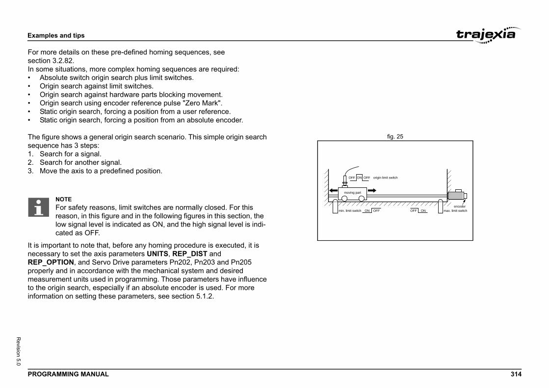
Exam
PROG 314
Revision 5.0
For msectioIn som• A• O• O• O• S• S
fig. 25The fseque1. S2. S3. M
It is imnecesREP_propemeasto theinform
origin limit switch
max. limit switchencoder
OFF ONOFF
ples and tips
RAMMING MANUAL
ore details on these pre-defined homing sequences, see n 3.2.82.e situations, more complex homing sequences are required:
bsolute switch origin search plus limit switches.rigin search against limit switches.rigin search against hardware parts blocking movement.rigin search using encoder reference pulse "Zero Mark".tatic origin search, forcing a position from a user reference.tatic origin search, forcing a position from an absolute encoder.
igure shows a general origin search scenario. This simple origin search nce has 3 steps:
earch for a signal.earch for another signal.ove the axis to a predefined position.
portant to note that, before any homing procedure is executed, it is sary to set the axis parameters UNITS, REP_DIST and OPTION, and Servo Drive parameters Pn202, Pn203 and Pn205 rly and in accordance with the mechanical system and desired urement units used in programming. Those parameters have influence origin search, especially if an absolute encoder is used. For more ation on setting these parameters, see section 5.1.2.
ONmin. limit switch
moving part
ON OFFOFF
NOTEFor safety reasons, limit switches are normally closed. For this reason, in this figure and in the following figures in this section, the low signal level is indicated as ON, and the high signal level is indi-cated as OFF.
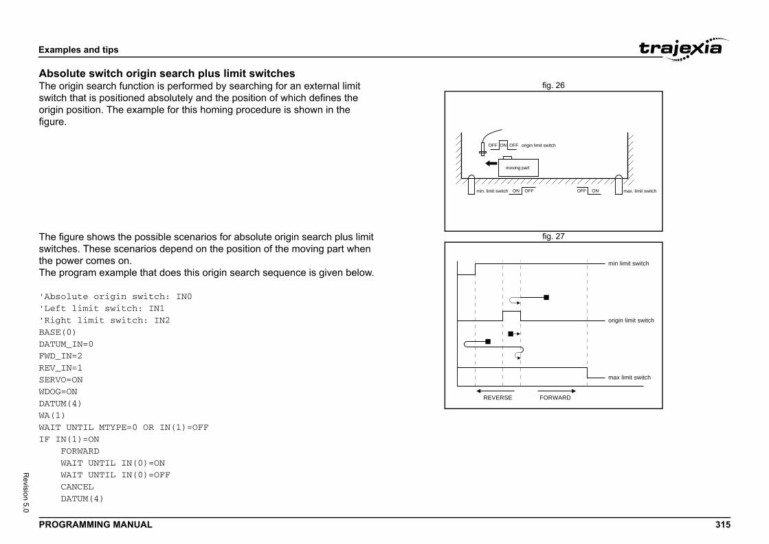
Exam
PROG 315
Revision 5.0
Absofig. 26The o
switchoriginfigure
fig. 27The fswitchthe pThe p
'Abso'Left'RighBASE(DATUMFWD_IREV_ISERVOWDOG=DATUMWA(1)WAIT IF IN F W W C D
origin limit switch
part
max. limit switchOFF ONOFF
FORWARD
min limit switch
origin limit switch
max limit switch
ples and tips
RAMMING MANUAL
lute switch origin search plus limit switchesrigin search function is performed by searching for an external limit that is positioned absolutely and the position of which defines the
position. The example for this homing procedure is shown in the .
igure shows the possible scenarios for absolute origin search plus limit es. These scenarios depend on the position of the moving part when
ower comes on.rogram example that does this origin search sequence is given below.
lute origin switch: IN0 limit switch: IN1t limit switch: IN20)_IN=0N=2N=1=ONON(4)
UNTIL MTYPE=0 OR IN(1)=OFF(1)=ONORWARDAIT UNTIL IN(0)=ONAIT UNTIL IN(0)=OFFANCELATUM(4)
ON OFFOFF
min. limit switch
moving
ON
REVERSE
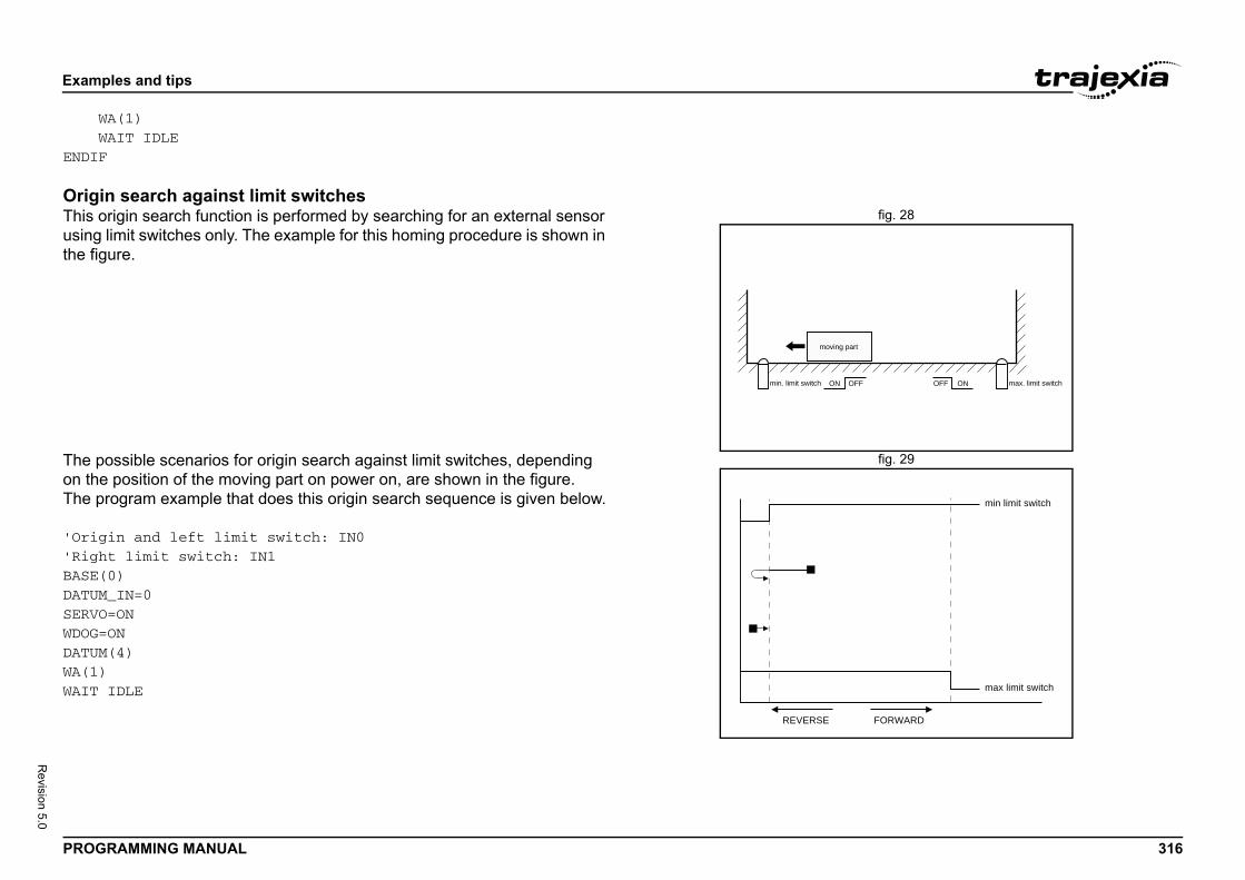
Exam
PROG 316
Revision 5.0
W WENDIF
Origfig. 28This o
usingthe fig
fig. 29The pon thThe p
'Orig'RighBASE(DATUMSERVOWDOG=DATUMWA(1)WAIT
OFF ONOFF
part
max. limit switch
FORWARD
min limit switch
max limit switch
ples and tips
RAMMING MANUAL
A(1)AIT IDLE
in search against limit switchesrigin search function is performed by searching for an external sensor
limit switches only. The example for this homing procedure is shown in ure.
ossible scenarios for origin search against limit switches, depending e position of the moving part on power on, are shown in the figure.rogram example that does this origin search sequence is given below.
in and left limit switch: IN0t limit switch: IN10)_IN=0=ONON(4)
IDLE
ONmin. limit switch
moving
REVERSE
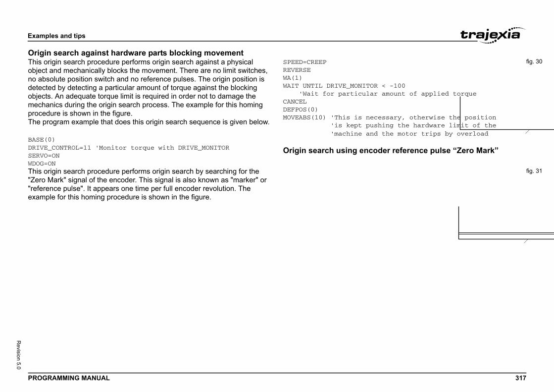
Exam
PROG 317
Revision 5.0
Origfig. 30This o
objecno abdetecobjecmechproceThe p
BASE(DRIVESERVOWDOG=
< -100 amount of applied torque
essary, otherwise the positionhing the hardware limit of the the motor trips by overload
der reference pulse “Zero Mark”
fig. 31This o"Zero"referexam
ples and tips
RAMMING MANUAL
in search against hardware parts blocking movementrigin search procedure performs origin search against a physical
t and mechanically blocks the movement. There are no limit switches, solute position switch and no reference pulses. The origin position is ted by detecting a particular amount of torque against the blocking ts. An adequate torque limit is required in order not to damage the anics during the origin search process. The example for this homing dure is shown in the figure.rogram example that does this origin search sequence is given below.
0)_CONTROL=11 'Monitor torque with DRIVE_MONITOR=ONON
SPEED=CREEPREVERSEWA(1)WAIT UNTIL DRIVE_MONITOR 'Wait for particularCANCELDEFPOS(0)MOVEABS(10) 'This is nec 'is kept pus 'machine and
Origin search using enco
rigin search procedure performs origin search by searching for the Mark" signal of the encoder. This signal is also known as "marker" or ence pulse". It appears one time per full encoder revolution. The ple for this homing procedure is shown in the figure.
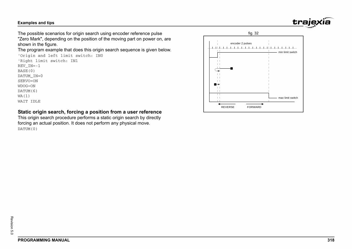
Exam
PROG 318
Revision 5.0
fig. 32The p"ZeroshowThe p'Orig'RighREV_IBASE(DATUMSERVOWDOG=DATUMWA(1)WAIT
StatiThis oforcinDATUM
FORWARD
min limit switch
er 2 pulses
max limit switch
ples and tips
RAMMING MANUAL
ossible scenarios for origin search using encoder reference pulse Mark", depending on the position of the moving part on power on, are n in the figure.rogram example that does this origin search sequence is given below.in and left limit switch: IN0t limit switch: IN1N=-10)_IN=0=ONON(6)
IDLE
c origin search, forcing a position from a user referencerigin search procedure performs a static origin search by directly g an actual position. It does not perform any physical move.(0)
REVERSE
encod
Exam
PROG 319
Revision 5.0
StatiThis oabsolwith a
5.1.6
Regisstorininformby theRegisregistAlso, interrused,inform
The aaxis paccurinput informCaptuProceprogr
The In Tracomminput on theused,refer The rthe syregist
ace and the TJ1-FL02, the registration is done 02. described below.
-II and Sigma-V Servo Drivend Sigma-V Servo Drive occurs when an axis is connected to the Trajexia system via the re are three registration inputs on these Servo
e latch, so only one input can be used at a time. e physical inputs are in pins CN1-44, CN1-45 N1 connector. For Sigma-V Servo Drives the 1-10, CN1-11 and CN1-12 on the 26-pins CN1
cal inputs EXT1, EXT2 and EXT3 to associate ones. This association is done by setting the o Drive. For more information on setting this eter, refer to the table below.
eter value Description
Not used
Input from CN1 pin44 (Rising edge)
Input from CN1 pin45 (Rising edge).
Input from CN1 pin46 (Rising edge).
Signal always OFF.
Signal always ON.
Not used
Input from CN1 pin44 (Falling edge).
Input from CN1 pin45 (Falling edge).
Input from CN1 pin46 (Falling edge).
EXT 1 As for EXT 1
EXT 1 As for EXT 1
ples and tips
RAMMING MANUAL
c origin search, forcing a position from an absolute encoderrigin search procedure sets the actual position to the position of an
ute encoder. It does not perform any physical move. It is only possible n axis with an absolute encoder in a control loop.
Registration
tration, also called ‘latch’ or ‘print registration’, is about real-time g of the position of an axis when an external input is activated. The ation that is registered, i.e. stored, is processed later, not in real time, application program.tration is different from processing an interrupt input or signal. With ration, no event is generated when the registration input is activated. the normal execution of the application program is not disturbed or upted. Only the position of an axis is stored. This information can be like other parameters or values, in a program. The registration ation is available to a program immediately after the registration.
dvantage of registration is that it is done very quickly. Therefore, the osition that is stored is very accurate. To achieve this speed and acy, registration is implemented with hardware, and the registration must be on the same board as the encoder input that provides ation on the axis position.ring and storing the axis position is done in real time by the hardware. ssing this information is done not in real time by the application am.
REGIST axis commandjexia, you do a registration with the REGIST axis command. This and takes one argument. This argument determines which external
is registered, whether the registration is executed on the rising edge or falling edge of the input signal, whether the windowing function is
and other options. For more information on the REGIST command, to sections 3.2.200, 3.2.201, 3.2.263, 3.2.264 and 3.2.265.egistration differs for different axes depending on their connection to stem. If an axis is connected via the MECHATROLINK-II bus, the ration is done in the Servo Drive hardware. If an axis is connected via
the Servo Drive analog interfin the hardware of the TJ1-FLThe different registrations are
Registration in the SigmaRegistration in the Sigma-II aassigned to this Servo Drive MECHATROLINK-II bus. TheDrives, but only one hardwarFor Sigma-II Servo Drives thand CN1-46 on the 50-pins Cphysical inputs are in pins CNconnector. Trajexia uses logithe physical inputs to logical parameter Pn511 of the Servassociation and Pn511 param/i
Registra-tion signal
Parameter number
Param
EXT 1 Pn511.1 0 to 3
4
5
6
7
8
9 to C
D
E
F
EXT 2 Pn511.2 As for
EXT 3 Pn511.3 As for
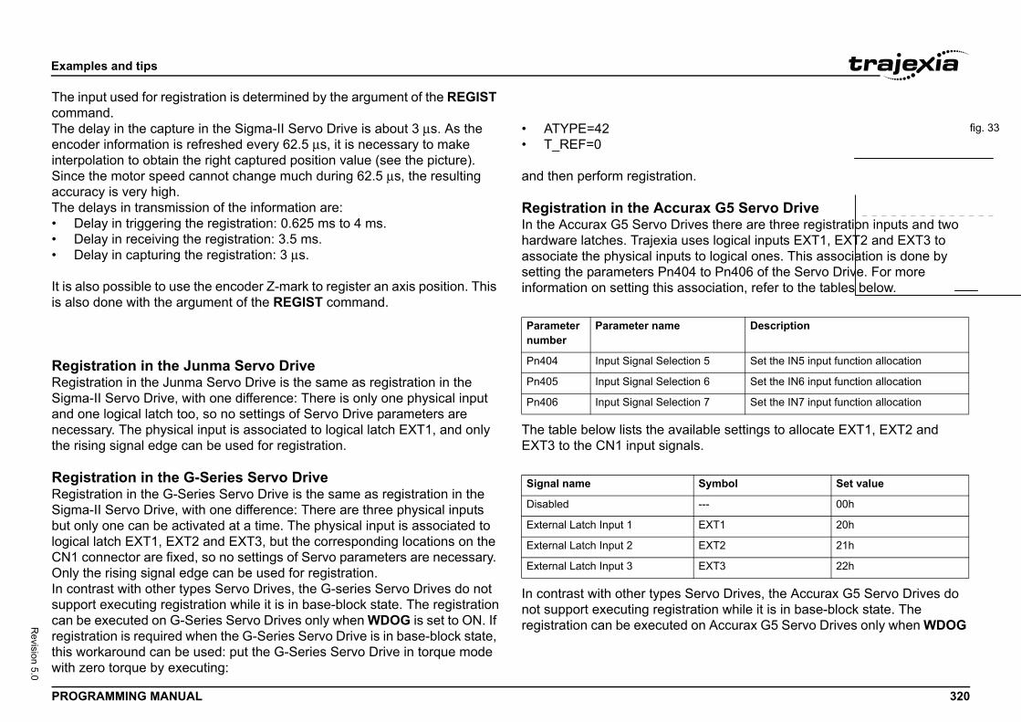
Exam
PROG 320
Revision 5.0
The incomm
fig. 33The dencodinterpSinceaccurThe d• D• D• D
It is ais als
RegiRegisSigmand onecesthe ris
RegiRegisSigmbut ologicaCN1 Only In consuppocan bregistthis wwith z
.
ax G5 Servo Drivees there are three registration inputs and twoes logical inputs EXT1, EXT2 and EXT3 to
to logical ones. This association is done by to Pn406 of the Servo Drive. For more
sociation, refer to the tables below.
ilable settings to allocate EXT1, EXT2 and ls.
ervo Drives, the Accurax G5 Servo Drives do ation while it is in base-block state. The on Accurax G5 Servo Drives only when WDOG
5
u
Description
n 5 Set the IN5 input function allocation
n 6 Set the IN6 input function allocation
n 7 Set the IN7 input function allocation
Symbol Set value
--- 00h
EXT1 20h
EXT2 21h
EXT3 22h
ples and tips
RAMMING MANUAL
put used for registration is determined by the argument of the REGIST and.elay in the capture in the Sigma-II Servo Drive is about 3 μs. As the er information is refreshed every 62.5 μs, it is necessary to make olation to obtain the right captured position value (see the picture). the motor speed cannot change much during 62.5 μs, the resulting acy is very high.elays in transmission of the information are:elay in triggering the registration: 0.625 ms to 4 ms.elay in receiving the registration: 3.5 ms.elay in capturing the registration: 3 μs.
lso possible to use the encoder Z-mark to register an axis position. This o done with the argument of the REGIST command.
stration in the Junma Servo Drivetration in the Junma Servo Drive is the same as registration in the a-II Servo Drive, with one difference: There is only one physical input ne logical latch too, so no settings of Servo Drive parameters are sary. The physical input is associated to logical latch EXT1, and only ing signal edge can be used for registration.
stration in the G-Series Servo Drivetration in the G-Series Servo Drive is the same as registration in the a-II Servo Drive, with one difference: There are three physical inputs nly one can be activated at a time. The physical input is associated to l latch EXT1, EXT2 and EXT3, but the corresponding locations on the
connector are fixed, so no settings of Servo parameters are necessary. the rising signal edge can be used for registration.trast with other types Servo Drives, the G-series Servo Drives do notrt executing registration while it is in base-block state. The registration
e executed on G-Series Servo Drives only when WDOG is set to ON. If ration is required when the G-Series Servo Drive is in base-block state, orkaround can be used: put the G-Series Servo Drive in torque mode ero torque by executing:
• ATYPE=42• T_REF=0
and then perform registration
Registration in the AccurIn the Accurax G5 Servo Drivhardware latches. Trajexia usassociate the physical inputssetting the parameters Pn404information on setting this as/i
The table below lists the avaEXT3 to the CN1 input signa/i
In contrast with other types Snot support executing registrregistration can be executed
Parameter number
Parameter name
Pn404 Input Signal Selectio
Pn405 Input Signal Selectio
Pn406 Input Signal Selectio
Signal name
Disabled
External Latch Input 1
External Latch Input 2
External Latch Input 3
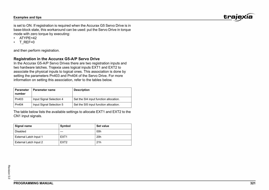
Exam
PROG 321
Revision 5.0
is setbase-mode• A• T
and t
RegiIn thetwo hassocsettininform/i
The tCN1 /i
Paramnumb
Pn40
Pn40
Signa
Disab
Exter
Exter
ples and tips
RAMMING MANUAL
to ON. If registration is required when the Accurax G5 Servo Drive is in block state, this workaround can be used: put the Servo Drive in torque with zero torque by executing:TYPE=42_REF=0
hen perform registration.
stration in the Accurax G5-A/P Servo Drive Accurax G5-A/P Servo Drives there are two registration inputs and ardware latches. Trajexia uses logical inputs EXT1 and EXT2 to iate the physical inputs to logical ones. This association is done by g the parameters Pn403 and Pn404 of the Servo Drive. For more ation on setting this association, refer to the tables below.
able below lists the available settings to allocate EXT1 and EXT2 to the input signals.
eter er
Parameter name Description
3 Input Signal Selection 4 Set the SI4 input function allocation.
4 Input Signal Selection 5 Set the SI5 input function allocation.
l name Symbol Set value
led --- 00h
nal Latch Input 1 EXT1 20h
nal Latch Input 2 EXT2 21h
Exam
PROG 322
Revision 5.0
RegiThe Tencodregisthow tsectioThe dcontinnecesone S
RegiThe Tfor ththe saof the3.2.2The dcontinnecesone S
UsinThereand Ruse th• R
dse
• Mna
• RsiRpase
ples and tips
RAMMING MANUAL
stration in the TJ1-FL02J1-FL02 has two physical registration inputs, and two latch circuits per er input, which can be used independently. Therefore two independent ration inputs can be used at the same time. For more information on o use both registration inputs of the TJ1-FL02 at the same time, refer to ns 3.2.200, 3.2.201, 3.2.263, 3.2.264 and 3.2.265.elay in the capture is 0.5 μs. Because the encoder position is read uously from the line-drive encoder input, interpolation is not sary. The delay for the transmission of the captured information is just ERVO_PERIOD cycle.
stration in the TJ2-KS02J2-KS02 has three physical registration inputs, and two latch circuits
e encoder input. Two independent registration inputs can be used at me time. For more information on how to use both registration inputs TJ1-FL02 at the same time, refer to sections 3.2.200, 3.2.201,
63, 3.2.264 and 3.2.265.elay in the capture is 0.5 μs. Because the encoder position is read uously from the line-drive encoder input, interpolation is not sary. The delay for the transmission of the captured information is just ERVO_PERIOD cycle.
g registration in application programs is one axis command (REGIST), and two axis parameters (MARK EG_POS). With these commands and parameter, you can control and e registration functionality in BASIC programs.
EGIST captures the axis position when a registration signal is etected. The available settings depend on the axis type. Refer to ction 3.2.265.ARK is a flag that signals whether the position has been captured or
ot. For the secondary registration input the parameter MARKB is vailable. For more information, refer to sections 3.2.200 and 3.2.201.EG_POS holds the captured axis position. Only if the MARK flag gnals that the position was captured successfully, you can regard the EG_POS value as valid. For the secondary registration input the rameter REG_POSB is available. For more information, refer to ctions 3.2.263 and 3.2.264.
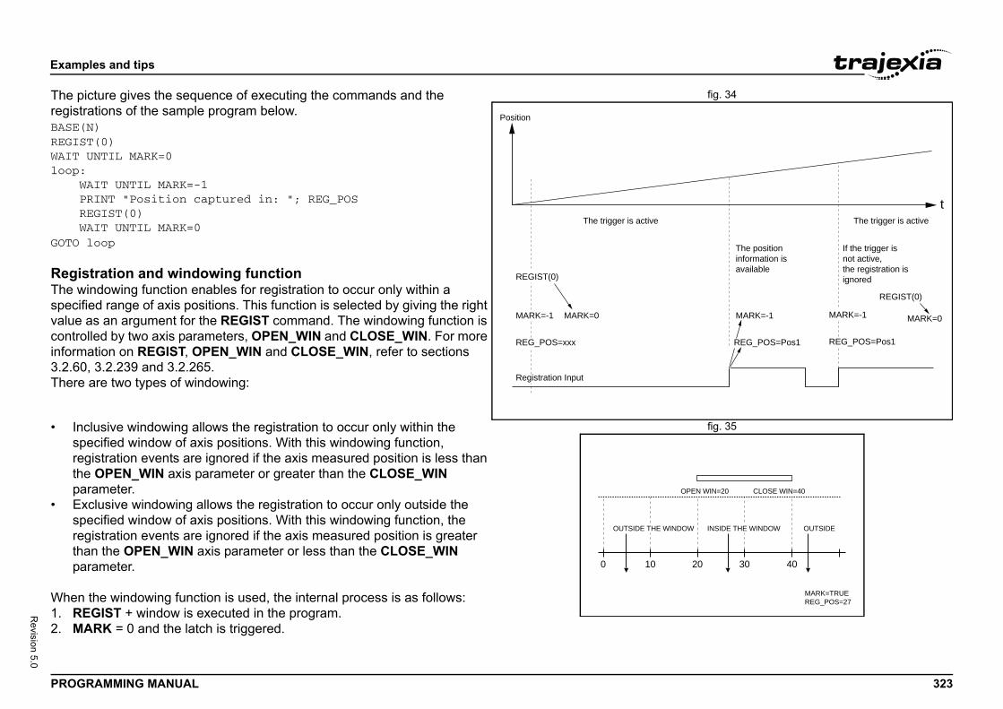
Exam
PROG 323
Revision 5.0
fig. 34The pregistBASE(REGISWAIT loop: W P R WGOTO
RegiThe wspecivaluecontroinform3.2.6There
fig. 35• Insprethpa
• Esprethpa
When1. R2. M
t
MARK=0
REGIST(0)
MARK=-1MARK=-1
REG_POS=Pos1REG_POS=Pos1
The trigger is active
If the trigger is not active, the registration is ignored
The position information is available
20 30 40
OW INSIDE THE WINDOW
OPEN WIN=20 CLOSE WIN=40
OUTSIDE
MARK=TRUEREG_POS=27
ples and tips
RAMMING MANUAL
icture gives the sequence of executing the commands and the rations of the sample program below.N)T(0)UNTIL MARK=0
AIT UNTIL MARK=-1RINT "Position captured in: "; REG_POSEGIST(0)AIT UNTIL MARK=0loop
stration and windowing functionindowing function enables for registration to occur only within a
fied range of axis positions. This function is selected by giving the right as an argument for the REGIST command. The windowing function is lled by two axis parameters, OPEN_WIN and CLOSE_WIN. For more ation on REGIST, OPEN_WIN and CLOSE_WIN, refer to sections
0, 3.2.239 and 3.2.265. are two types of windowing:
clusive windowing allows the registration to occur only within the ecified window of axis positions. With this windowing function, gistration events are ignored if the axis measured position is less than e OPEN_WIN axis parameter or greater than the CLOSE_WIN rameter.
xclusive windowing allows the registration to occur only outside the ecified window of axis positions. With this windowing function, the gistration events are ignored if the axis measured position is greater an the OPEN_WIN axis parameter or less than the CLOSE_WIN rameter.
the windowing function is used, the internal process is as follows:EGIST + window is executed in the program.ARK = 0 and the latch is triggered.
Position
Registration Input
REG_POS=xxx
The trigger is active
REGIST(0)
MARK=0MARK=-1
0 10
OUTSIDE THE WIND
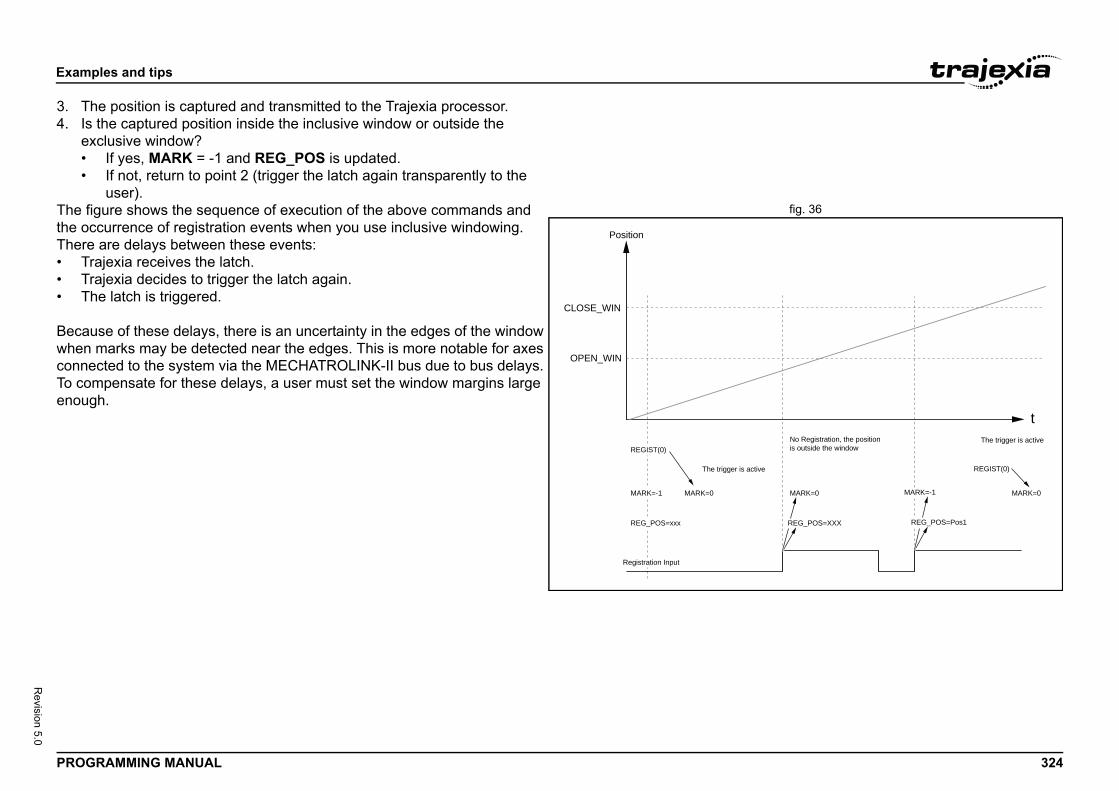
Exam
PROG 324
Revision 5.0
3. T4. Is
e••
fig. 36The fthe ocThere• T• T• T
BecawhenconneTo coenou
t
ive
MARK=0
REGIST(0)
MARK=-1MARK=0
REG_POS=Pos1REG_POS=XXX
The trigger is activeNo Registration, the position is outside the window
ples and tips
RAMMING MANUAL
he position is captured and transmitted to the Trajexia processor. the captured position inside the inclusive window or outside the xclusive window?
If yes, MARK = -1 and REG_POS is updated.If not, return to point 2 (trigger the latch again transparently to the user).
igure shows the sequence of execution of the above commands and currence of registration events when you use inclusive windowing. are delays between these events:
rajexia receives the latch.rajexia decides to trigger the latch again.he latch is triggered.
use of these delays, there is an uncertainty in the edges of the window marks may be detected near the edges. This is more notable for axes cted to the system via the MECHATROLINK-II bus due to bus delays.
mpensate for these delays, a user must set the window margins large gh.
Position
Registration Input
REG_POS=xxx
The trigger is act
REGIST(0)
MARK=0MARK=-1
CLOSE_WIN
OPEN_WIN
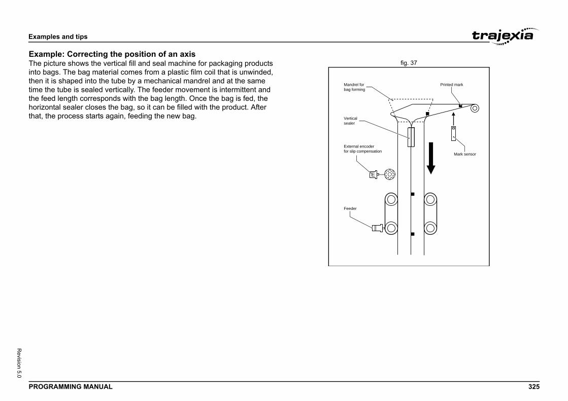
Exam
PROG 325
Revision 5.0
Examfig. 37The p
into bthen itime tthe fehorizothat,
Mark sensor
Printed mark
ples and tips
RAMMING MANUAL
ple: Correcting the position of an axisicture shows the vertical fill and seal machine for packaging products ags. The bag material comes from a plastic film coil that is unwinded, t is shaped into the tube by a mechanical mandrel and at the same he tube is sealed vertically. The feeder movement is intermittent and ed length corresponds with the bag length. Once the bag is fed, the ntal sealer closes the bag, so it can be filled with the product. After
the process starts again, feeding the new bag.
Mandrel forbag forming
Verticalsealer
External encoderfor slip compensation
E
Feeder
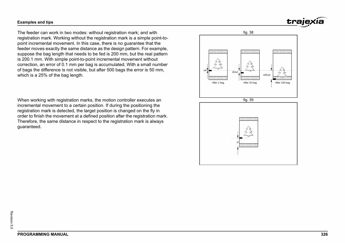
Exam
PROG 326
Revision 5.0
fig. 38The fregistpoint feedesuppois 200correof bagwhich
fig. 39WhenincremregistorderThereguara
After 20 bag After 100 bag
0d100d
D
ples and tips
RAMMING MANUAL
eeder can work in two modes: without registration mark; and with ration mark. Working without the registration mark is a simple point-to-incremental movement. In this case, there is no guarantee that the r moves exactly the same distance as the design pattern. For example, se the bag length that needs to be fed is 200 mm, but the real pattern .1 mm. With simple point-to-point incremental movement without
ction, an error of 0.1 mm per bag is accumulated. With a small number s the difference is not visible, but after 500 bags the error is 50 mm, is a 25% of the bag length.
working with registration marks, the motion controller executes an ental movement to a certain position. If during the positioning the
ration mark is detected, the target position is changed on the fly in to finish the movement at a defined position after the registration mark. fore, the same distance in respect to the registration mark is always nteed.
After 1 bag
d2
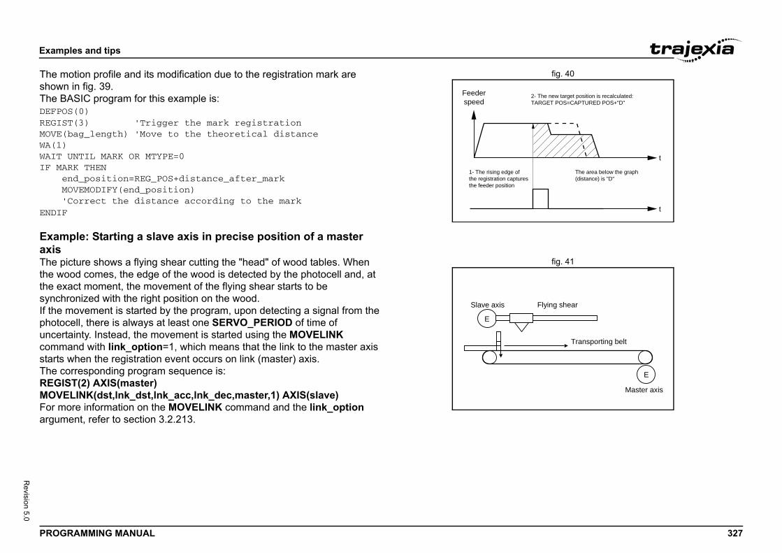
Exam
PROG 327
Revision 5.0
fig. 40The mshowThe BDEFPOREGISMOVE(WA(1)WAIT IF MA e M 'ENDIF
Examaxis
fig. 41The pthe wthe esynchIf thephotouncercommstartsThe cREGIMOVFor margum
t
t
2- The new target position is recalculated:TARGET POS=CAPTURED POS+"D"
The area below the graph(distance) is "D"
E
Master axis
Flying shear
Transporting belt
ples and tips
RAMMING MANUAL
otion profile and its modification due to the registration mark are n in fig. 39.ASIC program for this example is:S(0)T(3) 'Trigger the mark registrationbag_length) 'Move to the theoretical distance
UNTIL MARK OR MTYPE=0RK THENnd_position=REG_POS+distance_after_markOVEMODIFY(end_position)Correct the distance according to the mark
ple: Starting a slave axis in precise position of a master
icture shows a flying shear cutting the "head" of wood tables. When ood comes, the edge of the wood is detected by the photocell and, at xact moment, the movement of the flying shear starts to be ronized with the right position on the wood.
movement is started by the program, upon detecting a signal from the cell, there is always at least one SERVO_PERIOD of time of tainty. Instead, the movement is started using the MOVELINK and with link_option=1, which means that the link to the master axis
when the registration event occurs on link (master) axis.orresponding program sequence is:ST(2) AXIS(master)ELINK(dst,lnk_dst,lnk_acc,lnk_dec,master,1) AXIS(slave)ore information on the MOVELINK command and the link_option ent, refer to section 3.2.213.
1- The rising edge ofthe registration capturesthe feeder position
Feederspeed
E
Slave axis
Exam
PROG 328
Revision 5.0
fig. 42The pregistThe incan helimin
5.1.7
OsciThe soscilloparamtrouboscillomanuYou cparamdone of thestoredthe Tchangchang
on of manual triggering is that it requires user the start of tracing is not synchronized with the lso, with manual triggering the tracing range is annel.
a program, does not have the limitations of ng. Triggering by a program stores the axis and mory of the TJ2-MC__. Later, the parameters for graphical representation. The axis and d in the Table memory. The memory range eters of the SCOPE command. When the emory, the oscilloscope can be configured to
ry locations instead of axis and system nt when the tracing is started can be exactly
trolled by the TRIGGER command. This means
ples and tips
RAMMING MANUAL
icture shows how the position of the slave axis is corrected using the ration event on the master axis to start the movement of the slave axis. fluence of SERVO_PERIOD and the fact that the registration event
appen at any time inside the SERVO_PERIOD is completely ated.
Tracing and monitoring
lloscope functionality in Trajexia Studiooftware oscilloscope is a standard part of Trajexia Studio. The scope can be used to trace and graphically represent axis and system eters. This can help you with development, commissioning and
leshooting of the motion system. For more information on the software scope and its features and capabilities, refer to the Trajexia Studio
al.an trigger the oscilloscope to start tracing given axis and system eters in two ways: manually or by a program. Triggering manually is
using the data trace. The parameters are stored in the Table memory controller. The range of the Table memory where the parameters are can be set in the Memory Manager of the device configuration (see
rajexia Studio manual). With manual triggering, the user can see the es of axis and system parameters in real time, as the system runs. A e in parameter values is graphically represented as soon as the
change happens. The limitatiinteraction, which means thatmovement that is analysed. Alimited to 200 samples per ch
Using the oscilloscopeThe alternative, triggering bymanual triggering of the tracisystem parameters in the meare given to the oscilloscopesystem parameters are storeused is defined by the paramparameters are in the Table mshow a range of Table memoparameters. The exact momedetermined because it is con
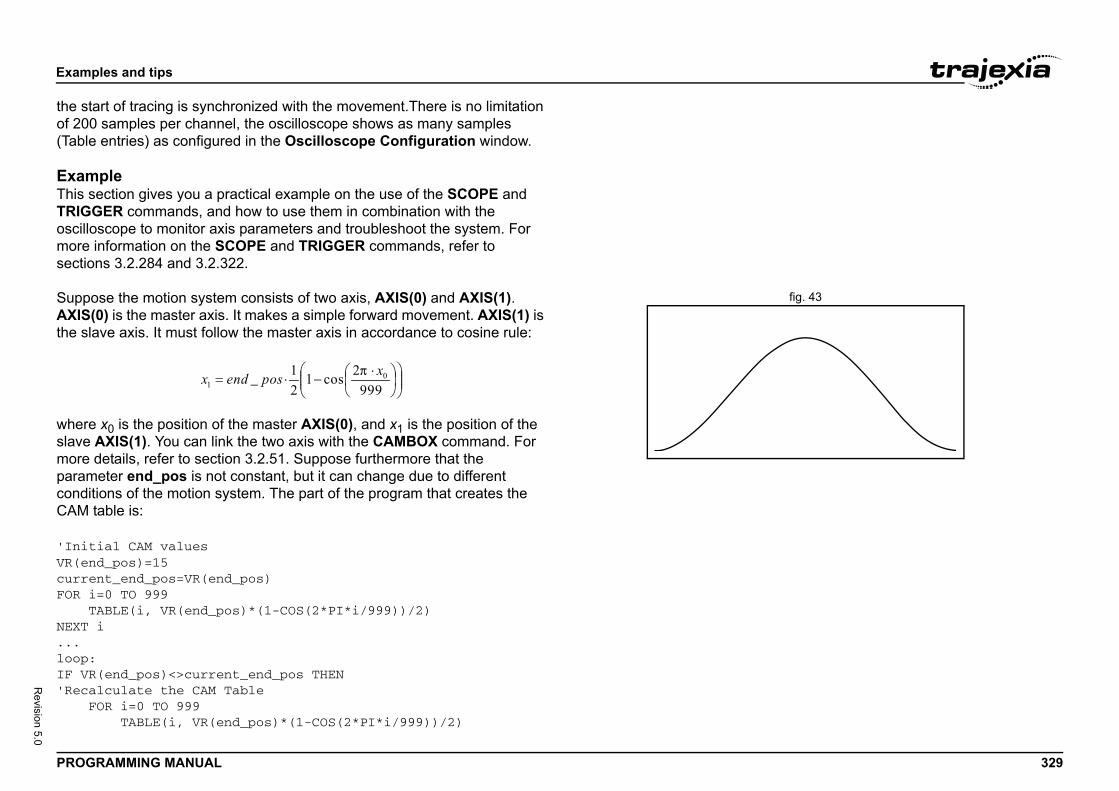
Exam
PROG 329
Revision 5.0
the stof 200(Table
ExamThis sTRIGoscillomoresectio
fig. 43SuppAXISthe sl
whereslavemoreparamcondiCAM
'InitVR(encurreFOR i TNEXT ...loop:IF VR'Reca F
ples and tips
RAMMING MANUAL
art of tracing is synchronized with the movement.There is no limitation samples per channel, the oscilloscope shows as many samples entries) as configured in the Oscilloscope Configuration window.
pleection gives you a practical example on the use of the SCOPE and
GER commands, and how to use them in combination with the scope to monitor axis parameters and troubleshoot the system. For
information on the SCOPE and TRIGGER commands, refer to ns 3.2.284 and 3.2.322.
ose the motion system consists of two axis, AXIS(0) and AXIS(1). (0) is the master axis. It makes a simple forward movement. AXIS(1) is ave axis. It must follow the master axis in accordance to cosine rule:
x0 is the position of the master AXIS(0), and x1 is the position of the AXIS(1). You can link the two axis with the CAMBOX command. For details, refer to section 3.2.51. Suppose furthermore that the eter end_pos is not constant, but it can change due to different
tions of the motion system. The part of the program that creates the table is:
ial CAM valuesd_pos)=15nt_end_pos=VR(end_pos)=0 TO 999ABLE(i, VR(end_pos)*(1-COS(2*PI*i/999))/2)i
(end_pos)<>current_end_pos THENlculate the CAM TableOR i=0 TO 999 TABLE(i, VR(end_pos)*(1-COS(2*PI*i/999))/2)
Exam
PROG 330
Revision 5.0
N cENDIF...GOTO
The VexternCAMThe caxis a
'InitFOR i B A U R R F D S A D D S CNEXT WDOG=BASE('Scop'1 sa'Info'Becachann'MPOS'DPOS
ples and tips
RAMMING MANUAL
EXT iurrent_end_pos=VR(end_pos)
loop
R(end_pos) value can be changed from some other program or ally from another controller using FINS messaging. In this case, the
table must be recalculated.reation of the CAM table is complete. The initialization of the desired nd system parameters for tracing is:
ializations=0 TO 1ASE(i)TYPE=40NITS=8192EP_DIST=20EP_OPTION=1E_LIMIT=1RIVE_CONTROL=11PEED=8CCEL=50ECEL=50EFPOS(0)ERVO=ONANCELiON1)e settings:mple each 2 servo cyclesrmation stored in TABLE(1000) to TABLE(4999)use we capture 4 channels, we have 1000 samples per el. AXIS(0) is stored in TABLE(1000) to TABLE(1999) AXIS(1) is stored in TABLE(2000) to TABLE(2999)
Exam
PROG 331
Revision 5.0
'Torq'TABL'MSPE'The SCOPEFORWATRIGGWHILE ' C W ' ' ' ' ' ' I E WWENDHALT
ples and tips
RAMMING MANUAL
ue reference for AXIS(1) is stored inE(3000) to TABLE(3999)ED AXIS(1) is stored in TABLE(4000) to TABLE(4999)capture covers 1000 samples * 2ms / sample = 2seconds(ON,2,1000,4999,MPOS AXIS(0),DPOS,DRIVE_MONITOR,MSPEED)RD AXIS(0) 'Move the master axis forwardER 'Start tracing and storing of parameters NOT MOTION_ERRORCambox that will start in AXIS(0) position 1AMBOX(0,999,UNITS,10,0,2,1)AIT UNTIL MPOS AXIS(0)<1The capture will start when the master axis is ina position Between 0 and 1. Additional conditionsare:- The previous capture has finished(SCOPE_POS=1000)- We have the permission (VR(activate_trigger)=ON)F SCOPE_POS=1000 AND VR(activate_trigger)=ON THEN TRIGGER PRINT "Triggered"NDIFAIT IDLE
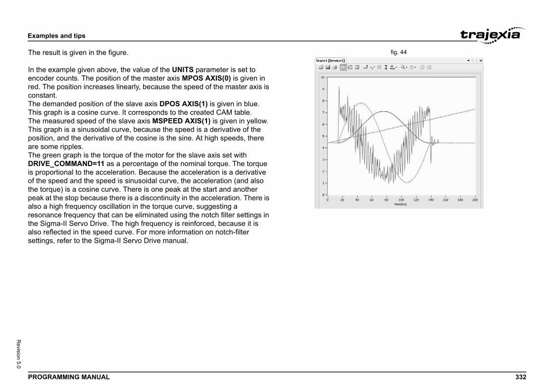
Exam
PROG 332
Revision 5.0
fig. 44The r
In theencodred. TconstThe dThis gThe mThis gpositiare soThe gDRIVis proof thethe topeak also aresonthe Salso rsettin
ples and tips
RAMMING MANUAL
esult is given in the figure.
example given above, the value of the UNITS parameter is set to er counts. The position of the master axis MPOS AXIS(0) is given in he position increases linearly, because the speed of the master axis is ant.emanded position of the slave axis DPOS AXIS(1) is given in blue. raph is a cosine curve. It corresponds to the created CAM table.easured speed of the slave axis MSPEED AXIS(1) is given in yellow. raph is a sinusoidal curve, because the speed is a derivative of the
on, and the derivative of the cosine is the sine. At high speeds, there me ripples.reen graph is the torque of the motor for the slave axis set with E_COMMAND=11 as a percentage of the nominal torque. The torque portional to the acceleration. Because the acceleration is a derivative speed and the speed is sinusoidal curve, the acceleration (and also rque) is a cosine curve. There is one peak at the start and another at the stop because there is a discontinuity in the acceleration. There is high frequency oscillation in the torque curve, suggesting a ance frequency that can be eliminated using the notch filter settings in igma-II Servo Drive. The high frequency is reinforced, because it is eflected in the speed curve. For more information on notch-filter gs, refer to the Sigma-II Servo Drive manual.
Exam
PROG 333
Revision 5.0
TrouWhenentrieyou wan exexpla
The pdepenruns ican ctheseparamthe Crarelyend_CAMdemaand tha discand eThe sThe oeverywhereparamby arrprogrset toof theinitialstart oapplicusuala SHESuppfractio
ples and tips
RAMMING MANUAL
bleshooting with the oscilloscope the desired data is captured and recorded into the Table memory s, you can use the oscilloscope to visualize this data. This can help hen you commission and troubleshoot the system. This section gives ample of how a bug, which is difficult to analyse, can be clearly ined and solved using the captured data and the oscilloscope.
arameter end_pos, which defines the values in the CAM table, ds on external conditions of the system. Therefore a program that
n another task or even a controlling device using FINS communication, hange it while the main program that links two axis runs. Suppose that changes in conditions, which result in a change of the end_pos eter, happen most of the time when the axes are not linked, i.e. when
AMBOX command is not executed. Suppose furthermore that very the condition changes when the axes are linked. The change of the pos parameter triggers the recalculation of the CAM table while the BOX command is executed. The consequence is that the part of the nded position of the slave axis follows the profile before the change, e other part follows the profile after the change. In the end this leads to ontinuation of the profile, which causes an indefinite speed of the axis nds up with this error: the WDOG goes off, and all axes stop.cenario above is hard to analyse when you do not know what happens. nly thing that the user sees is that the slave axis has an error once few hours or even less often. But the oscilloscope can clearly show the problem is. In order to be able to use the oscilloscope, all desired eters must be captured at the time of an error. This can be achieved anging the application programs in a certain way. The good amming practice suggests to have a separate start-up program that is run automatically on power-up of the system and checks the integrity system, whether all the expected devices are connected and ized. It is recommended to let the start-up program, when it is finished, nly one program that takes care of the safety and integrity of the ation and execution of all other application programs. This program is ly referred to as a SHELL program. For more information on designing LL program, see section 5.2.1.
ose that program is designed in a way the it contains a following n of code:
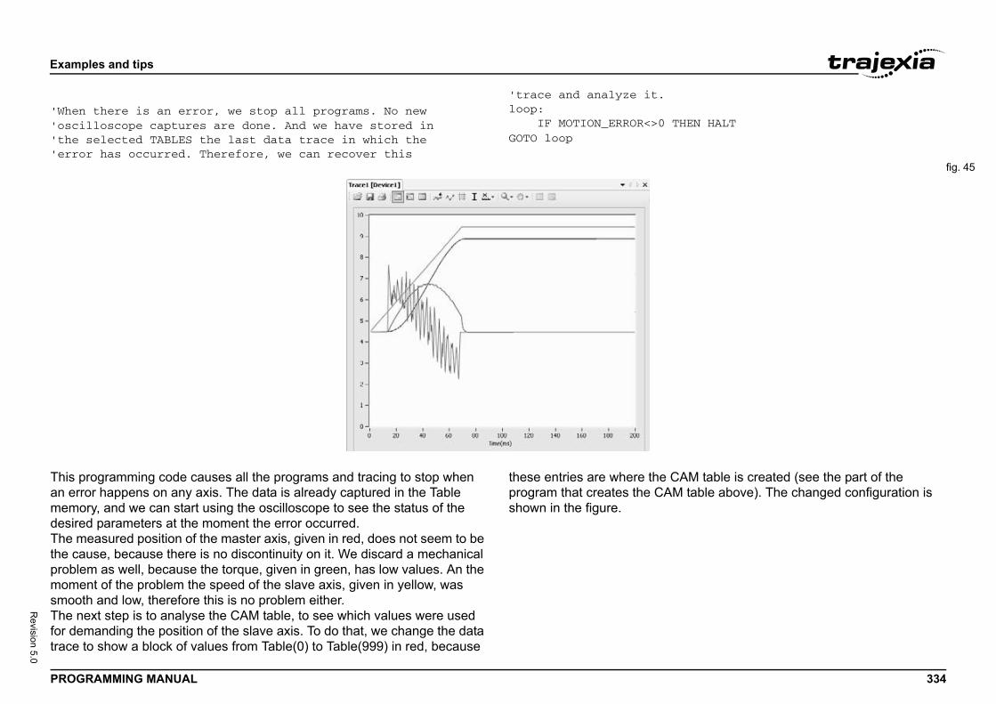
Exam
PROG 334
Revision 5.0
'When'osci'the 'erro
HEN HALT
fig. 45
This pan ermemodesireThe mthe caproblemomesmooThe nfor detrace
AM table is created (see the part of the table above). The changed configuration is
ples and tips
RAMMING MANUAL
there is an error, we stop all programs. No newlloscope captures are done. And we have stored inselected TABLES the last data trace in which ther has occurred. Therefore, we can recover this
'trace and analyze it.loop: IF MOTION_ERROR<>0 TGOTO loop
rogramming code causes all the programs and tracing to stop when ror happens on any axis. The data is already captured in the Table ry, and we can start using the oscilloscope to see the status of the d parameters at the moment the error occurred.easured position of the master axis, given in red, does not seem to be use, because there is no discontinuity on it. We discard a mechanical m as well, because the torque, given in green, has low values. An the nt of the problem the speed of the slave axis, given in yellow, was
th and low, therefore this is no problem either.ext step is to analyse the CAM table, to see which values were used manding the position of the slave axis. To do that, we change the data to show a block of values from Table(0) to Table(999) in red, because
these entries are where the Cprogram that creates the CAMshown in the figure.
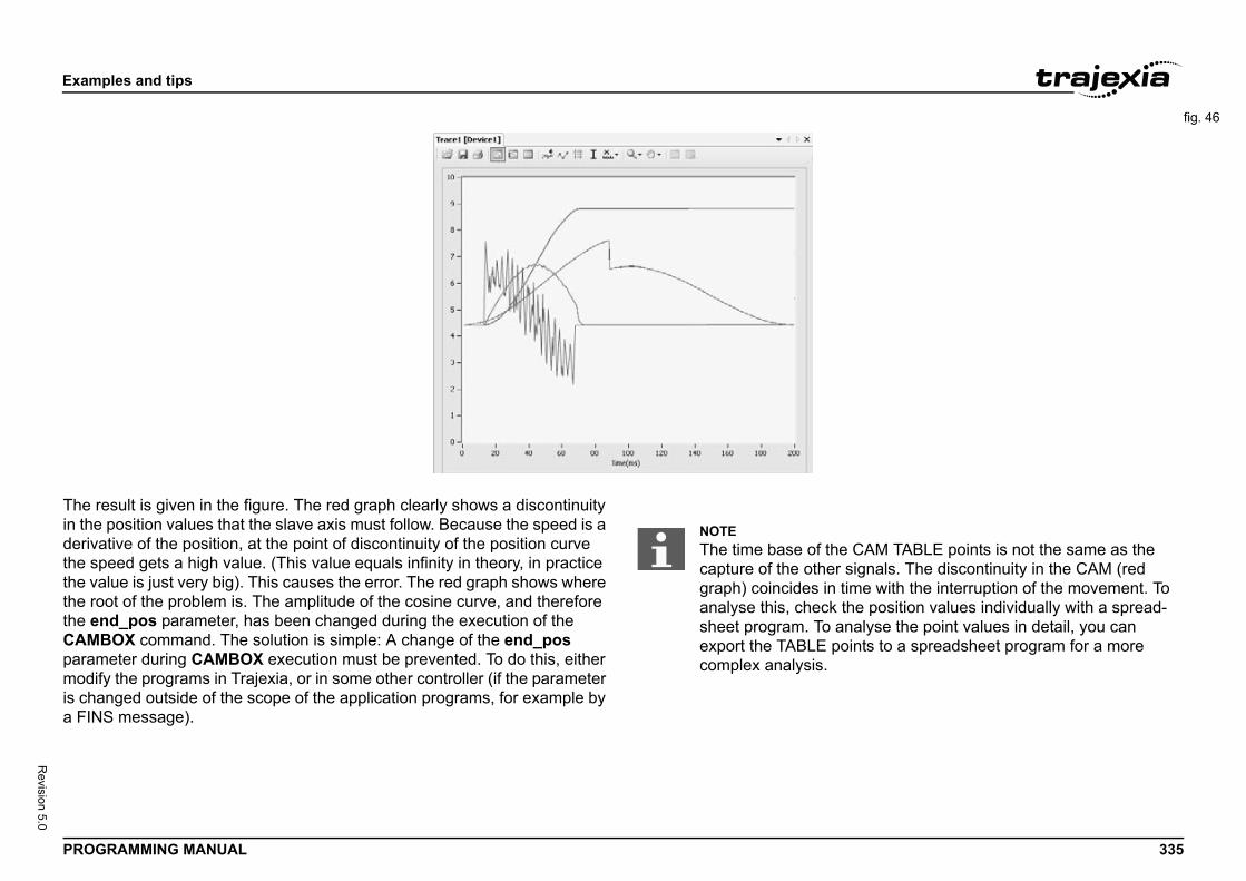
Exam
PROG 335
Revision 5.0
fig. 46
The rin thederivathe spthe vathe rothe eCAMparammodifis chaa FIN
CAM TABLE points is not the same as the signals. The discontinuity in the CAM (red ime with the interruption of the movement. To the position values individually with a spread-nalyse the point values in detail, you can ints to a spreadsheet program for a more
ples and tips
RAMMING MANUAL
esult is given in the figure. The red graph clearly shows a discontinuity position values that the slave axis must follow. Because the speed is a tive of the position, at the point of discontinuity of the position curve eed gets a high value. (This value equals infinity in theory, in practice lue is just very big). This causes the error. The red graph shows where ot of the problem is. The amplitude of the cosine curve, and therefore
nd_pos parameter, has been changed during the execution of the BOX command. The solution is simple: A change of the end_pos eter during CAMBOX execution must be prevented. To do this, either
y the programs in Trajexia, or in some other controller (if the parameter nged outside of the scope of the application programs, for example by S message).
NOTEThe time base of thecapture of the other graph) coincides in tanalyse this, check sheet program. To aexport the TABLE pocomplex analysis.
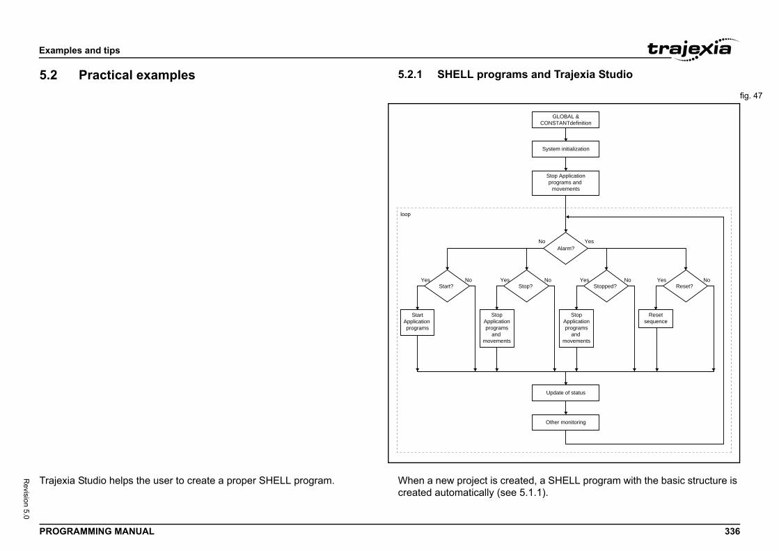
Exam
PROG 336
Revision 5.0
5.2 and Trajexia Studio
fig. 47
Traje d, a SHELL program with the basic structure is 1.1).
Stop Applicationprograms and
movements
YesNo
System initialization
Other monitoring
Resetsequence
Update of status
GLOBAL &CONSTANTdefinition
Alarm?
No
StopApplicationprograms
and movements
p?Yes No
Stopped?Yes No
Reset?
ples and tips
RAMMING MANUAL
Practical examples 5.2.1 SHELL programs
xia Studio helps the user to create a proper SHELL program. When a new project is createcreated automatically (see 5.
loop
StopApplicationprograms
and movements
StartApplication programs
Yes NoStart?
YesSto
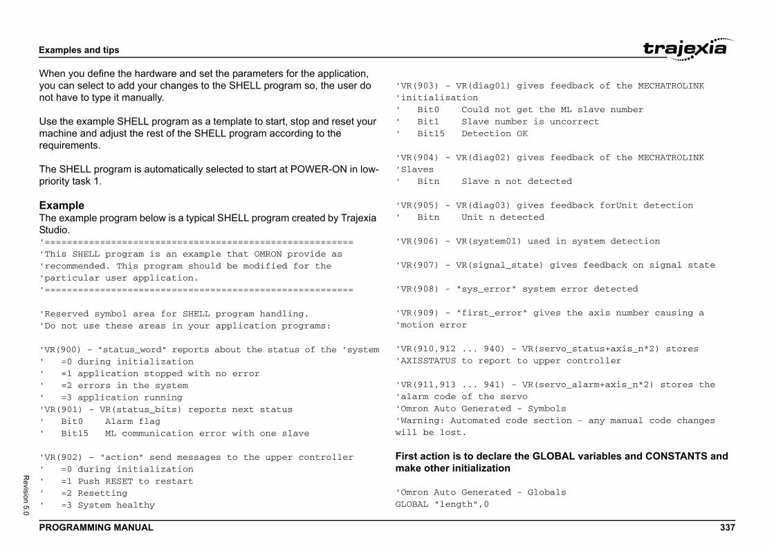
Exam
PROG 337
Revision 5.0
Whenyou cnot h
Use tmachrequir
The Spriorit
ExamThe eStudi'===='This'reco'part'====
'Rese'Do n
'VR(9' =' =' =' ='VR(9' B' B
'VR(9' =' =' =' =
ves feedback of the MECHATROLINK
t the ML slave number is uncorrect
ves feedback of the MECHATROLINK
detected
ves feedback forUnit detectionted
used in system detection
te) gives feedback on signal state
ystem error detected
gives the axis number causing a
R(servo_status+axis_n*2) stores upper controller
R(servo_alarm+axis_n*2) stores the
Symbols section - any manual code changes
e GLOBAL variables and CONSTANTS and
Globals
ples and tips
RAMMING MANUAL
you define the hardware and set the parameters for the application, an select to add your changes to the SHELL program so, the user do ave to type it manually.
he example SHELL program as a template to start, stop and reset your ine and adjust the rest of the SHELL program according to the ements.
HELL program is automatically selected to start at POWER-ON in low-y task 1.
plexample program below is a typical SHELL program created by Trajexia
o.==================================================== SHELL program is an example that OMRON provide as mmended. This program should be modified for the icular user application.====================================================
rved symbol area for SHELL program handling.ot use these areas in your application programs:
00) - "status_word" reports about the status of the 'system0 during initialization1 application stopped with no error2 errors in the system3 application running01) - VR(status_bits) reports next statusit0 Alarm flagit15 ML communication error with one slave
02) - "action" send messages to the upper controller0 during initialization1 Push RESET to restart2 Resetting3 System healthy
'VR(903) - VR(diag01) gi'initialisation' Bit0 Could not ge' Bit1 Slave number' Bit15 Detection OK
'VR(904) - VR(diag02) gi'Slaves' Bitn Slave n not
'VR(905) - VR(diag03) gi' Bitn Unit n detec
'VR(906) - VR(system01)
'VR(907) - VR(signal_sta
'VR(908) - "sys_error" s
'VR(909) - "first_error"'motion error
'VR(910,912 ... 940) - V'AXISSTATUS to report to
'VR(911,913 ... 941) - V'alarm code of the servo'Omron Auto Generated - 'Warning: Automated codewill be lost.
First action is to declare thmake other initialization
'Omron Auto Generated - GLOBAL "length",0
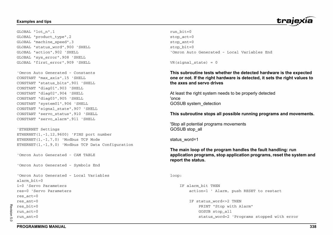
Exam
PROG 338
Revision 5.0
GLOBAGLOBAGLOBAGLOBAGLOBAGLOBAGLOBA
'OmroCONSTCONSTCONSTCONSTCONSTCONSTCONSTCONSTCONST
'ETHEETHERETHERETHER
'Omro
'Omro
'Omroalarmi=0 'res=0res_ares_ares_brun_arun_a
Local Variables End
her the detected hardware is the expected ware is detected, it sets the right values to
ds to be properly detected
ossible running programs and movements.
ovements
am handles the fault handling: run application programs, reset the system and
, push RESET to restart
2 THENwith Alarm"ll2 'Programs stopped with error
ples and tips
RAMMING MANUAL
L "lot_n",1L "product_type",2L "machine_speed",3L "status_word",900 'SHELLL "action",902 'SHELLL "sys_error",908 'SHELLL "first_error",909 'SHELL
n Auto Generated - ConstantsANT "max_axis",15 'SHELLANT "status_bits",901 'SHELLANT "diag01",903 'SHELLANT "diag02",904 'SHELLANT "diag03",905 'SHELLANT "system01",906 'SHELLANT "signal_state",907 'SHELLANT "servo_status",910 'SHELLANT "servo_alarm",911 'SHELL
RNET SettingsNET(1,-1,12,9600) 'FINS port numberNET(1,-1,7,0) 'Modbus TCP ModeNET(1,-1,9,0) 'Modbus TCP Data Configuration
n Auto Generated - CAM TABLE
n Auto Generated - Symbols End
n Auto Generated - Local Variables_bit=0Servo Parameters 'Servo Parametersct=0nt=0it=0ct=0nt=0
run_bit=0stop_act=0stop_ant=0stop_bit=0'Omron Auto Generated -
VR(signal_state) = 0
This subroutine tests whetone or not. If the right hardthe axes and servo drives
At least the right system nee'onceGOSUB system_detection
This subroutine stops all p
'Stop all potential programs mGOSUB stop_all
status_word=1
The main loop of the prograpplication programs, stopreport the status.
loop:
IF alarm_bit THEN action=1 ' Alarm
IF status_word<> PRINT "Stop GOSUB stop_a status_word=
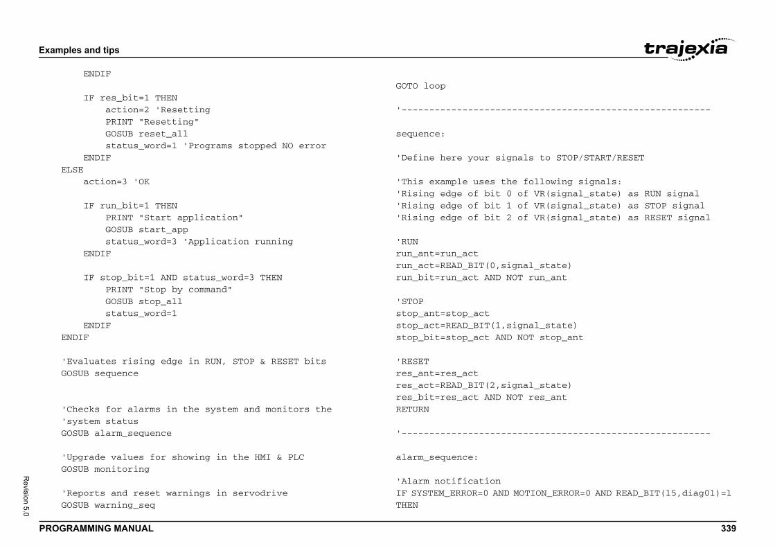
Exam
PROG 339
Revision 5.0
E
E
' G
' ' G
' G
' G
---------------------------------
s to STOP/START/RESET
ollowing signals: VR(signal_state) as RUN signal VR(signal_state) as STOP signal VR(signal_state) as RESET signal
l_state)run_ant
al_state)T stop_ant
l_state)res_ant
---------------------------------
TION_ERROR=0 AND READ_BIT(15,diag01)=1
ples and tips
RAMMING MANUAL
ENDIF
IF res_bit=1 THEN action=2 'Resetting PRINT "Resetting" GOSUB reset_all status_word=1 'Programs stopped NO error ENDIFLSE action=3 'OK
IF run_bit=1 THEN PRINT "Start application" GOSUB start_app status_word=3 'Application running ENDIF
IF stop_bit=1 AND status_word=3 THEN PRINT "Stop by command" GOSUB stop_all status_word=1 ENDIFNDIF
Evaluates rising edge in RUN, STOP & RESET bitsOSUB sequence
Checks for alarms in the system and monitors the system statusOSUB alarm_sequence
Upgrade values for showing in the HMI & PLCOSUB monitoring
Reports and reset warnings in servodriveOSUB warning_seq
GOTO loop
'-----------------------
sequence:
'Define here your signal
'This example uses the f'Rising edge of bit 0 of'Rising edge of bit 1 of'Rising edge of bit 2 of
'RUNrun_ant=run_actrun_act=READ_BIT(0,signarun_bit=run_act AND NOT
'STOPstop_ant=stop_actstop_act=READ_BIT(1,signstop_bit=stop_act AND NO
'RESETres_ant=res_actres_act=READ_BIT(2,signares_bit=res_act AND NOT RETURN
'-----------------------
alarm_sequence:
'Alarm notificationIF SYSTEM_ERROR=0 AND MOTHEN
Exam
PROG 340
Revision 5.0
aELSE I E aENDIF
'MECHFOR i B V ' I ELSE ENEXT
sRETUR
---------------------------------
application program is stoppednts are cancelled and all the axesodify this section if you requireure
T(-1)
YPE
ssible program buffer
---------------------------------
programs that should be started
---------------------------------
ples and tips
RAMMING MANUAL
larm_bit=0
F MOTION_ERROR<>0 THEN SET_BIT(0,status_bits) 'Motion error flag first_error=ERROR_AXISNDIFlarm_bit=1
ATROLINK axis alarm monitoring=0 TO max_axisASE(i)R(servo_status+i*2)=AXISSTATUSif stopped by alarm, notify the alarm codeF ATYPE>=40 AND ATYPE<=42 THEN IF status_word=2 THEN 'if no response, notify "communication alarm" IF (AXISSTATUS AND 4)<>0 THEN VR(servo_alarm+i*2)=$E6 ELSEIF NOT DRIVE_ALARM(servo_alarm+i*2) THEN VR(servo_alarm+i*2)=$E6 ELSEIF VR(servo_alarm+i*2)=0 THEN VR(servo_alarm+i*2)=$bb ENDIF 'if no alarm, notify RUN=$99 or BaseBlock=$BB ELSEIF(DRIVE_STATUS AND 8) THEN VR(servo_alarm+i*2)=$99
VR(servo_alarm+i*2)=$bb ENDIFNDIFi
ys_error=SYSTEM_ERRORN
'-----------------------
stop_all:
'In this example, if the'suddenly all the moveme'are set to BaseBlock. M'a different STOP proced
STOP "APPLICATION"WDOG=0
FOR i= 0 TO max_axis BASE(i) IF MARK=0 THEN REGIS AXIS_ENABLE=0 SERVO=0 CANCEL(1) 'Cancel NT WA(1) CANCEL(1) 'Cancel poNEXT i
RAPIDSTOP 'Cancel MTYPERETURN
'-----------------------
start_app:
'Add all the application'with the START signal
RUN "APPLICATION"
RETURN
'-----------------------
Exam
PROG 341
Revision 5.0
reset
'UncoIF RE
'MECHFOR i B I VR(se ' ' ENEXT 'ReseDATUMCLEAR
'MECHIF (S
'Omro
section - any manual code changes
ML IO End
IO devicesHENneeds initialisation of the system
---------------------------------
HENrning if any
xis
AND ATYPE<=42 THENE_STATUS AND 2)>0 THEN DRIVE_CLEAR
---------------------------------
g on the application
ples and tips
RAMMING MANUAL
_all:
rrect system settingAD_BIT(15,diag01)=0 THEN GOSUB system_detection
ATROLINK axes reset sequence=0 TO max_axisASE(i)F ATYPE>=40 AND ATYPE<=42 THEN 'Reset sequence for MECHATROLINK communication error IF (AXISSTATUS AND 4)<>0 THEN PRINT "Resetting ML alarm" GOSUB system_detection ENDIF 'Reset sequence for DRIVE errors IF (AXISSTATUS AND 8)<>0 THEN IF VR(servo_alarm+i*2)=$81 OR rvo_alarm+i*2)=$CC THEN GOSUB absencoder ELSEPending to handle diferently those alarms that cannotbe resetted with DRIVE_CLEAR DRIVE_CLEAR ENDIF ENDIFNDIFit sequence for AXIS error(0)_BIT(0,status_bits)
ATROLINK devices reset sequenceYSTEM_ERROR AND $40000)<>0 THEN
n Auto Generated - ML IO
'Warning: Automated code'will be lost.
'Omron Auto Generated -
'Same with the otherELSEIF SYSTEM_ERROR<>0 T 'Other system error EXENDIF
RETURN
'-----------------------
warning_seq:
IF READ_BIT(15,diag01) T 'Clear servodrive wa IF res_bit=1 THEN FOR i=0 TO max_a BASE(i) IF ATYPE>=40 IF (DRIV ENDIF NEXT i ENDIFENDIFRETURN
'-----------------------
monitoring:
'Add monitoring dependinRETURN
Exam
PROG 342
Revision 5.0
'----
absen'To bRETUR
'----
syste
statuactioVR(st
'Omro'Warn'will
'UnitVR(diVR(diVR(diVR(sy
ples and tips
RAMMING MANUAL
----------------------------------------------------
coder:e implemented in the futureN
----------------------------------------------------
m_detection:
s_word=0n=0atus_bits)=0
n Auto Generated - Unitsing: Automated code section - any manual code changes be lost.
Variables resetag01)=0ag02)=0ag03)=0stem01)=0
Exam
PROG 343
Revision 5.0
'Unit' ML0IF CO P SENDIF
' FL IF CO P SENDIF
'Star
'MECHIF RE ' M
' I E E
' I PRI E P E
Y address0,4,1,system01) THENddress for ML04 unit 0, station 1")<> $44 THENss for ML04 unit 0, station 1")
on
iag02)=0 AND VR(diag03)=0 THEN
Units End
THEN
param_v/mask/size4)4)F,2)
SJDE-02ANA-OY
ples and tips
RAMMING MANUAL
Detection4 UnitMMSTYPE SLOT(0) <> 36 THENRINT "Error Comms Type for unit 0 is not ML04"ET_BIT(0,diag03)
UnitMMSTYPE SLOT(1) <> 33 THENRINT "Error Comms Type for unit 1 is not FL"ET_BIT(1,diag03)
t Mechatrolink Section
ATROLINK device detection for ML04 unit 0AD_BIT(0,diag03) = 0 THENInitialise MechatrolinkECHATROLINK(0,0)
Device countF NOT MECHATROLINK(0,3,system01) THEN PRINT "Error getting device count for ML04 unit 0" SET_BIT(0,diag01)LSEIF VR(system01) <> 2 THEN PRINT "Incorrect device count for ML04 unit 0" SET_BIT(1,diag01)NDIF
Check SJDE-02ANA-OY addressF NOT MECHATROLINK(0,4,0,system01) THENNT "Error getting address for ML04 unit 0, station 0" SET_BIT(0,diag02)LSEIF VR(system01) <> $43 THENRINT "Incorrect address for ML04 unit 0, station 0" SET_BIT(0,diag02)NDIF
' Check SJDE-02ANA-O IF NOT MECHATROLINK( PRINT "Error getting a SET_BIT(1,diag02 ELSEIF VR(system01) PRINT "Incorrect addre SET_BIT(1,diag02 ENDIF
ENDIF
'Stop Mechatrolink Secti
'Detection OKIF VR(diag01)=0 AND VR(dSET_BIT(15,diag01)
'Invert input channelsINVERT_IN(16,OFF) 'POTINVERT_IN(17,OFF) 'NOT
'Omron Auto Generated -
'Start Standard Section
IF READ_BIT(15,diag01)=1
'Drive Parameters
BASE(2)'Parameter data param_n/TABLE(0,$20E,32,$FFFFFF,TABLE(4,$210,45,$FFFFFF,TABLE(8,$515,$800,$FFF0FTABLE(12,-1)MECHATROLINK(0,20,$43) 'REGIST(-1)
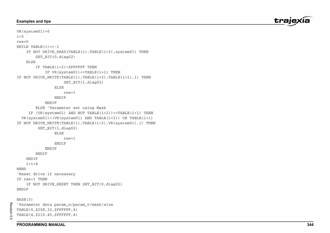
Exam
PROG 344
Revision 5.0
VR(syi=0res=0WHILE I E IF NO VR(IF NO E iWEND'ReseIF re IENDIF
BASE('ParaTABLETABLE
ples and tips
RAMMING MANUAL
stem01)=0
TABLE(i)<>-1F NOT DRIVE_READ(TABLE(i),TABLE(i+3),system01) THEN SET_BIT(0,diag02)LSE IF TABLE(i+2)=$FFFFFF THEN IF VR(system01)<>TABLE(i+1) THENT DRIVE_WRITE(TABLE(i),TABLE(i+3),TABLE(i+1),1) THEN SET_BIT(1,diag02) ELSE res=1 ENDIF ENDIF ELSE 'Parameter set using MaskIF (VR(system01) AND NOT TABLE(i+2))<>TABLE(i+1) THENsystem01)=(VR(system01) AND TABLE(i+2)) OR TABLE(i+1)T DRIVE_WRITE(TABLE(i),TABLE(i+3),VR(system01),1) THEN SET_BIT(1,diag02) ELSE res=1 ENDIF ENDIF ENDIFNDIF=i+4
t drive if necessarys=1 THENF NOT DRIVE_RESET THEN SET_BIT(0,diag02)
3)meter data param_n/param_v/mask/size(0,$20E,32,$FFFFFF,4)(4,$210,45,$FFFFFF,4)
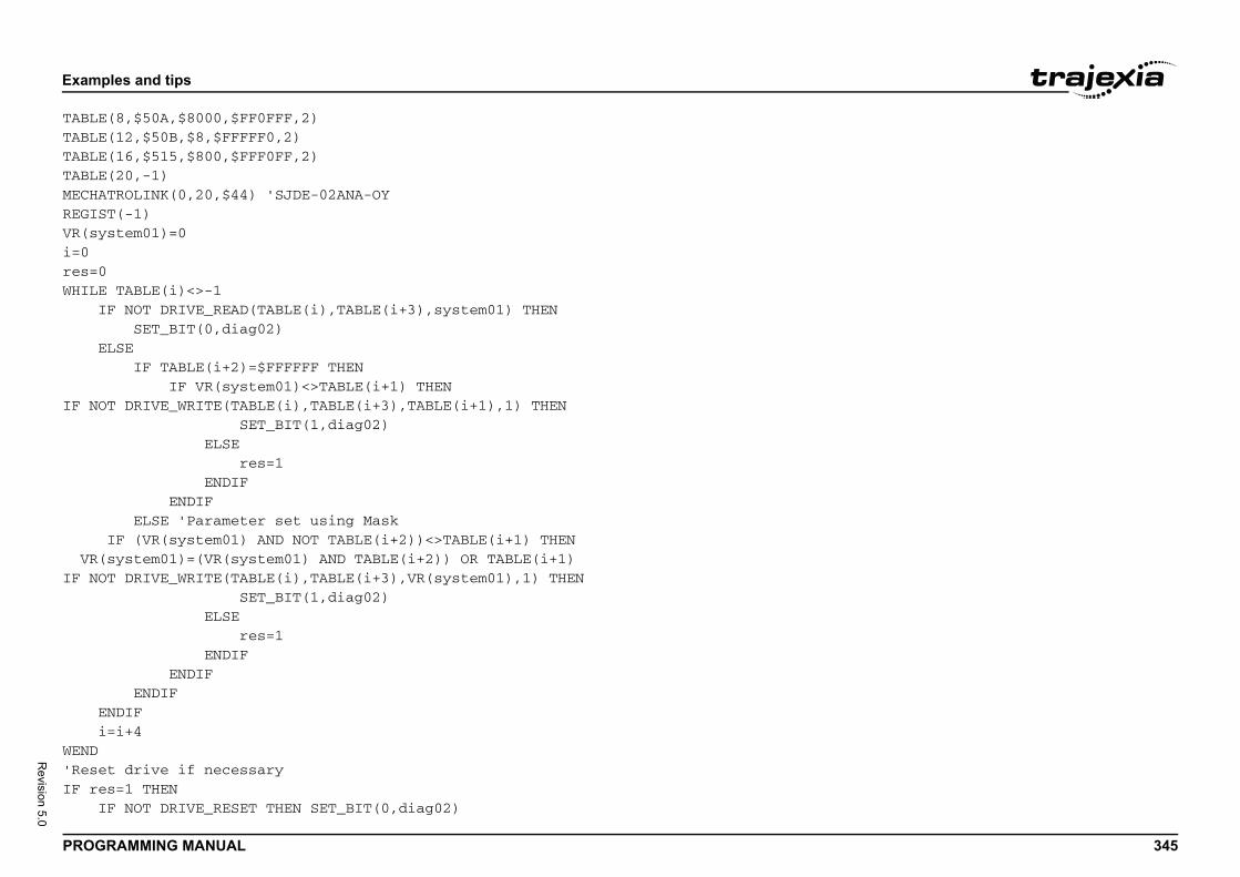
Exam
PROG 345
Revision 5.0
TABLETABLETABLETABLEMECHAREGISVR(syi=0res=0WHILE I E IF NO VR(IF NO E iWEND'ReseIF re I
ples and tips
RAMMING MANUAL
(8,$50A,$8000,$FF0FFF,2)(12,$50B,$8,$FFFFF0,2)(16,$515,$800,$FFF0FF,2)(20,-1)TROLINK(0,20,$44) 'SJDE-02ANA-OYT(-1)stem01)=0
TABLE(i)<>-1F NOT DRIVE_READ(TABLE(i),TABLE(i+3),system01) THEN SET_BIT(0,diag02)LSE IF TABLE(i+2)=$FFFFFF THEN IF VR(system01)<>TABLE(i+1) THENT DRIVE_WRITE(TABLE(i),TABLE(i+3),TABLE(i+1),1) THEN SET_BIT(1,diag02) ELSE res=1 ENDIF ENDIF ELSE 'Parameter set using MaskIF (VR(system01) AND NOT TABLE(i+2))<>TABLE(i+1) THENsystem01)=(VR(system01) AND TABLE(i+2)) OR TABLE(i+1)T DRIVE_WRITE(TABLE(i),TABLE(i+3),VR(system01),1) THEN SET_BIT(1,diag02) ELSE res=1 ENDIF ENDIF ENDIFNDIF=i+4
t drive if necessarys=1 THENF NOT DRIVE_RESET THEN SET_BIT(0,diag02)

Exam
PROG 346
Revision 5.0
ENDIF
' Axi
BASE(ATYPEUNITSREP_DREP_OERRORAXIS_DRIVEP_GAII_GAID_GAIOV_GAVFF_GSPEEDACCELDECELCREEPJOGSPFE_LISERVOFWD_IREV_IDATUMFHOLDFS_LIRS_LIFASTDFHSPEOUTLIFE_RADAC=0
ples and tips
RAMMING MANUAL
s Parameters
0) 'Axis Name: Flex00=44 'Axis Type: Flexible_Servo=1024.0000IST=5000000.0000PTION=0MASK=268ENABLE=0_CONTROL=0N=1.0000N=0.0000N=0.0000IN=0.0000AIN=0.0000=50.0000=100.0000=100.0000=100.0000EED=100.0000MIT=10.0000=0N=-1.0000N=-1.0000_IN=-1.0000_IN=-1.0000MIT=20000000.0000MIT=-20000000.0000EC=0.0000ED=1000.0000MIT=1.0000NGE=0.0000.0000

Exam
PROG 347
Revision 5.0
BASE(ATYPEUNITSREP_DREP_OERRORAXIS_DRIVEP_GAII_GAID_GAIOV_GAVFF_GSPEEDACCELDECELCREEPJOGSPFE_LISERVOFWD_IREV_IDATUMFHOLDFS_LIRS_LIFASTDFHSPEOUTLIFE_RADAC=0
BASE(ATYPEUNITSREP_D
ples and tips
RAMMING MANUAL
1) 'Axis Name: Flex01=44 'Axis Type: Flexible_Servo=1024.0000IST=5000000.0000PTION=0MASK=268ENABLE=0_CONTROL=0N=1.0000N=0.0000N=0.0000IN=0.0000AIN=0.0000=50.0000=100.0000=100.0000=100.0000EED=100.0000MIT=10.0000=0N=-1.0000N=-1.0000_IN=-1.0000_IN=-1.0000MIT=20000000.0000MIT=-20000000.0000EC=0.0000ED=1000.0000MIT=1.0000NGE=0.0000.0000
2) 'Axis Name: Down=40 'Axis Type: Mechatro_Position=32.0000IST=360000.0000

Exam
PROG 348
Revision 5.0
REP_OERRORAXIS_DRIVESPEEDACCELDECELCREEPJOGSPFE_LISERVOFWD_IREV_IDATUMFHOLDFS_LIRS_LIFASTDFHSPEOUTLIFE_RA
BASE(ATYPEUNITSREP_DREP_OERRORAXIS_DRIVESPEEDACCELDECELCREEPJOGSPFE_LI
ples and tips
RAMMING MANUAL
PTION=0MASK=268ENABLE=0_CONTROL=0=3600.0000=36000.0000=36000.0000=100.0000EED=100.0000MIT=90.0000=0N=16.0000N=17.0000_IN=-1.0000_IN=-1.0000MIT=20000000.0000MIT=-20000000.0000EC=0.0000ED=1000.0000MIT=1.0000NGE=0.0000
3) 'Axis Name: Up=40 'Axis Type: Mechatro_Position=32.0000IST=360.0000PTION=1MASK=268ENABLE=0_CONTROL=0=3600.0000=36000.0000=36000.0000=100.0000EED=100.0000MIT=90.0000

Exam
PROG 349
Revision 5.0
SERVOFWD_IREV_IDATUMFHOLDFS_LIRS_LIFASTDFHSPEOUTLIFE_RA
ENDIF
' Var
' TAB
'Stop
RETUR
ples and tips
RAMMING MANUAL
=0N=-1.0000N=-1.0000_IN=-1.0000_IN=-1.0000MIT=20000000.0000MIT=-20000000.0000EC=0.0000ED=1000.0000MIT=1.0000NGE=0.0000
iables
LE DATA
Standard Section
N
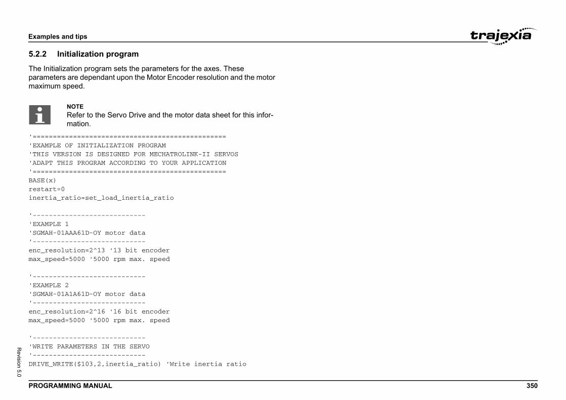
Exam
PROG 350
Revision 5.0
5.2.2
The Iparammaxim
'===='EXAM'THIS'ADAP'====BASE(restainert
'----'EXAM'SGMA'----enc_rmax_s
'----'EXAM'SGMA'----enc_rmax_s
'----'WRIT'----DRIVE
ples and tips
RAMMING MANUAL
Initialization program
nitialization program sets the parameters for the axes. These eters are dependant upon the Motor Encoder resolution and the motor um speed.
============================================PLE OF INITIALIZATION PROGRAM VERSION IS DESIGNED FOR MECHATROLINK-II SERVOST THIS PROGRAM ACCORDING TO YOUR APPLICATION============================================x)rt=0ia_ratio=set_load_inertia_ratio
------------------------PLE 1H-01AAA61D-OY motor data------------------------esolution=2^13 '13 bit encoderpeed=5000 '5000 rpm max. speed
------------------------PLE 2H-01A1A61D-OY motor data------------------------esolution=2^16 '16 bit encoderpeed=5000 '5000 rpm max. speed
------------------------E PARAMETERS IN THE SERVO------------------------_WRITE($103,2,inertia_ratio) 'Write inertia ratio
NOTERefer to the Servo Drive and the motor data sheet for this infor-mation.
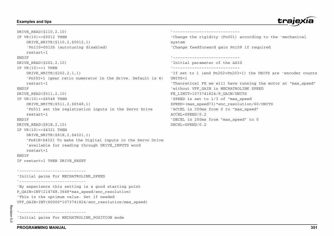
Exam
PROG 351
Revision 5.0
DRIVEIF VR D ' rENDIFDRIVEIF VR D ' rENDIFDRIVEIF VR D ' rENDIFDRIVEIF VR D ' ' rENDIFIF re
'----'Init'----'By eP_GAI'ThisVFF_G
'----'Init
-----001) according to the 'mechanical
Pn109 if required
-----e AXIS-----Pn203=1) the UNITS are 'encoder counts
have running the motor at "max_speed"HATROLINK SPEEDIN/UNITS"max_speedresolution/60/UNITSo "max_speed"
x_speed" to 0
ples and tips
RAMMING MANUAL
_READ($110,2,10)(10)<>$0012 THENRIVE_WRITE($110,2,$0012,1) Pn110=0012h (autotuning disabled)estart=1
_READ($202,2,10)(10)<>1 THENRIVE_WRITE($202,2,1,1)Pn202=1 (gear ratio numerator in the drive. Default is 4)estart=1
_READ($511,2,10)(10)<>$6548 THENRIVE_WRITE($511,2,$6548,1)Pn511 set the registration inputs in the Servo Driveestart=1
_READ($81E,2,10)(10)<>$4321 THENRIVE_WRITE($81E,2,$4321,1)Pn81E=$4321 To make the Digital inputs in the Servo Driveavailable for reading through DRIVE_INPUTS wordestart=1
start=1 THEN DRIVE_RESET
------------------------ial gains For MECHATROLINK_SPEED------------------------xperience this setting is a good starting pointN=INT(214748.3648*max_speed/enc_resolution) is the optimum value. Set if neededAIN=INT(60000*1073741824/enc_resolution/max_speed)
------------------------ial gains For MECHATROLINK_POSITION mode
'-----------------------'Change the rigidity (Fnsystem'Change feedforward gain
'-----------------------'Initial parameter of th'-----------------------'If set to 1 (and Pn202=UNITS=1'Theoretical FE we will 'without VFF_GAIN in MECFE_LIMIT=1073741824/P_GA'SPEED is set to 1/3 of SPEED=(max_speed73)*enc_'ACCEL in 200ms from 0 tACCEL=SPEED/0.2'DECEL in 200ms from "maDECEL=SPEED/0.2
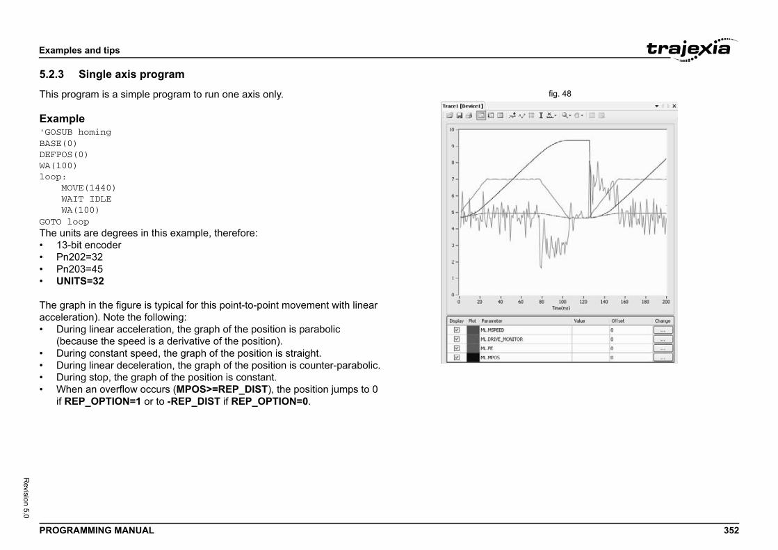
Exam
PROG 352
Revision 5.0
5.2.3fig. 48This p
Exam'GOSUBASE(DEFPOWA(10loop: M W WGOTO The u• 1• P• P• U
The gaccel• D
(b• D• D• D• W
if
ples and tips
RAMMING MANUAL
Single axis program
rogram is a simple program to run one axis only.
pleB homing0)S(0)0)
OVE(1440)AIT IDLEA(100)loopnits are degrees in this example, therefore:
3-bit encodern202=32n203=45NITS=32
raph in the figure is typical for this point-to-point movement with linear eration). Note the following:uring linear acceleration, the graph of the position is parabolic ecause the speed is a derivative of the position).uring constant speed, the graph of the position is straight.uring linear deceleration, the graph of the position is counter-parabolic.uring stop, the graph of the position is constant.hen an overflow occurs (MPOS>=REP_DIST), the position jumps to 0 REP_OPTION=1 or to -REP_DIST if REP_OPTION=0.
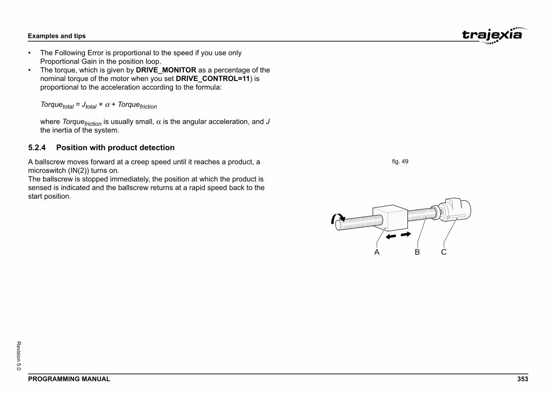
Exam
PROG 353
Revision 5.0
• TP
• Tnp
To
wth
5.2.4fig. 49A bal
microThe bsensestart p
B C
ples and tips
RAMMING MANUAL
he Following Error is proportional to the speed if you use only roportional Gain in the position loop.he torque, which is given by DRIVE_MONITOR as a percentage of the ominal torque of the motor when you set DRIVE_CONTROL=11) is roportional to the acceleration according to the formula:
rquetotal = Jtotal × α + Torquefriction
here Torquefriction is usually small, α is the angular acceleration, and J e inertia of the system.
Position with product detection
lscrew moves forward at a creep speed until it reaches a product, a switch (IN(2)) turns on. allscrew is stopped immediately, the position at which the product is d is indicated and the ballscrew returns at a rapid speed back to the osition.
A
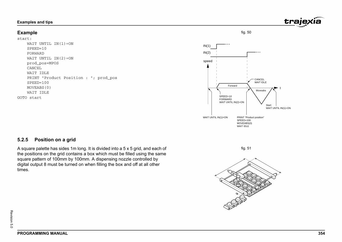
Exam
PROG 354
Revision 5.0
fig. 50Examstart W S F W p C W P S M WGOTO
5.2.5fig. 51A squ
the posquardigitatimes
rward
Moveabst
CANCELWAIT IDLE
PRINT "Product position"SPEED=100MOVEABS(0)WAIT IDLE
Start:WAIT UNTIL IN(1)=ON
IL IN(2)=ON
ples and tips
RAMMING MANUAL
ple:AIT UNTIL IN(1)=ONPEED=10ORWARDAIT UNTIL IN(2)=ONrod_pos=MPOSANCELAIT IDLERINT "Product Position : "; prod_posPEED=100OVEABS(0)AIT IDLEstart
Position on a grid
are palette has sides 1m long. It is divided into a 5 x 5 grid, and each of sitions on the grid contains a box which must be filled using the same e pattern of 100mm by 100mm. A dispensing nozzle controlled by l output 8 must be turned on when filling the box and off at all other .
speed
Fo
IN(1)
IN(2)
WAIT UNTIL IN(1)=ON
SPEED=10FORWARDWAIT UNT
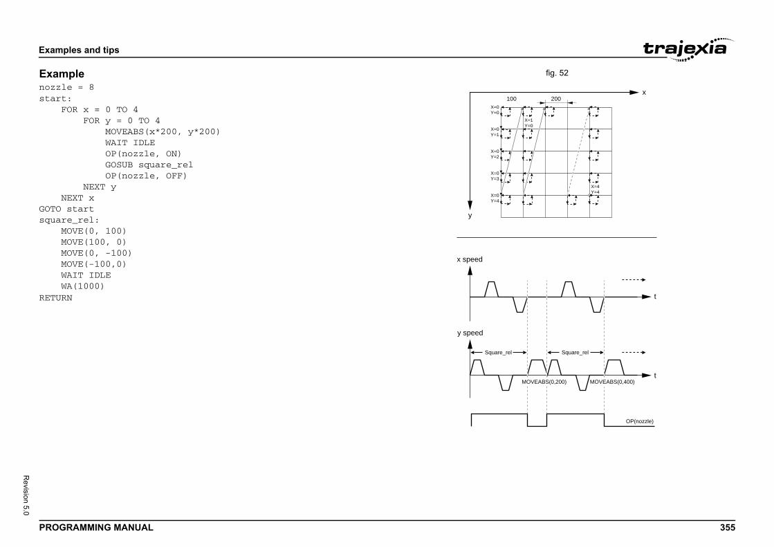
Exam
PROG 355
Revision 5.0
fig. 52Examnozzlstart F NGOTO squar M M M M W WRETUR t
t
x
X=1Y=0
X=4Y=4
200
Square_rel
OVEABS(0,200) MOVEABS(0,400)
OP(nozzle)
ples and tips
RAMMING MANUAL
plee = 8:OR x = 0 TO 4 FOR y = 0 TO 4 MOVEABS(x*200, y*200) WAIT IDLE OP(nozzle, ON) GOSUB square_rel OP(nozzle, OFF) NEXT yEXT xstarte_rel:OVE(0, 100)OVE(100, 0)OVE(0, -100)OVE(-100,0)AIT IDLEA(1000)N
y
x speed
y speed
Square_rel
X=0Y=0
X=0Y=1
X=0Y=2
X=0Y=3
X=0Y=4
100
M

Exam
PROG 356
Revision 5.0
5.2.6fig. 53A bag
opera
Bag f• W
co• W
The pmach
ples and tips
RAMMING MANUAL
Bag feeder program
feeder machine feeds plastic film a fixed distance that is set by the tor. The figure shows a typical bag feeder that is part of the machine.
eeder machines have two modes.ithout mark: Forward feeds the film a set distance, for films of a flat lourith mark: Forward feeds the film to a printed mark on the film.
rogram in this section shows the typical code for a bag feeder ine.

Exam
PROG 357
Revision 5.0
Examfig. 54
'===='BAG '===='Work'theo'a nu'A di'the '====
'Varistartmax_fprogrfailefeedeBASE('Posi'and UNITSSPEEDACCELDECELREP_DREP_OSERVOWDOG=
Time
Time
MARK=FALSEMark not detected,no correction
MOVEABS
MOVEABS REGIST(1)
WAIT IDLE DEFPOS(0)
ples and tips
RAMMING MANUAL
ple
============================================FEEDER program============================================ing with marks, if any mark is missing, feed theretical distance. But if the mark is missing formber of consecutive bags, stop the operation.gital output is activated a certain time to cutbag.============================================
able initialisation_signal=7ail=3am_alarm=0d=0r_axis=2feeder_axis)tion counter (MPOS,DPOS) goes from 0 to 999999 0 again=27=100=1000=1000IST=1000000PTION=1=ONON
Position
Speed MARK=TRUEMOVEMODIFY
Bag_distance-expected_pos+REG_POS
Bag_distance
REG_POS
MOVEABS REGIST(1)
WAIT IDLE DEFPOS(0)
IN(start_signal)
Exam
PROG 358
Revision 5.0
'Mainloop: 'as ze D
'Digit ' WIN(st WIN(st
' M Wverifbeing
'activ 'triggtrigg IMARK E
'finis W(MARK
'
ples and tips
RAMMING MANUAL
program
Define current position roEFPOS(0)
Wait for rising edge in al Input"start_signal"AIT UNTIL art_signal)=0AIT UNTIL art_signal)=1
Move bag lengthOVEABS(bag_distance)AIT UNTIL MTYPE=2 'To y that the MOVEABS is executed
If we work with Mark, ate the triggerMARK=FALSE when ered and TRUE when not eredF work_with_mark AND THEN REGIST(1) WAIT UNTIL MARK=0NDIF
Wait until movement hed or mark detectedAIT UNTIL MTYPE=0 OR AND work_with_mark)
Working with mark
IF work_with_mark THEN IF MARK THEN 'If the mark has been detected, the position is corrected MOVEMODIFY(bag_distance-expected_pos+REG_POS) failed=0
ELSE 'If the mark has not been detected PRINT "Mark not detected" failed=failed+1 IF failed>max_fail THEN 'After several consecutive misdetection stop the application PRINT "Mark definitelly lost" program_alarm=3 STOP ENDIF ENDIF ENDIF
'Wait until the feed movement has finished WAIT IDLEGOTO loop
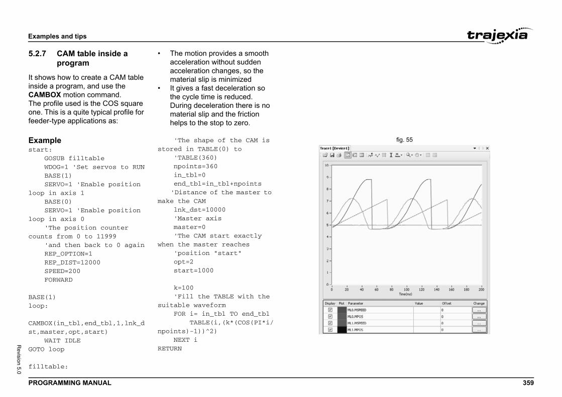
Exam
PROG 359
Revision 5.0
5.2.7
It shoinsideCAMThe pone. Tfeede
fig. 55Examstart G W B Sloop B Sloop 'count ' R R S F
BASE(loop: CAMBOst,ma WGOTO
fillt
ples and tips
RAMMING MANUAL
CAM table inside a program
ws how to create a CAM table a program, and use the
BOX motion command.rofile used is the COS square his is a quite typical profile for
r-type applications as:
• The motion provides a smooth acceleration without sudden acceleration changes, so the material slip is minimized
• It gives a fast deceleration so the cycle time is reduced. During deceleration there is no material slip and the friction helps to the stop to zero.
ple:OSUB filltableDOG=1 'Set servos to RUNASE(1)ERVO=1 'Enable position in axis 1ASE(0)ERVO=1 'Enable position in axis 0The position counter s from 0 to 11999and then back to 0 againEP_OPTION=1EP_DIST=12000PEED=200ORWARD
1)
X(in_tbl,end_tbl,1,lnk_dster,opt,start)AIT IDLEloop
able:
'The shape of the CAM is stored in TABLE(0) to 'TABLE(360) npoints=360 in_tbl=0 end_tbl=in_tbl+npoints 'Distance of the master to make the CAM lnk_dst=10000 'Master axis master=0 'The CAM start exactly when the master reaches 'position "start" opt=2 start=1000
k=100 'Fill the TABLE with the suitable waveform FOR i= in_tbl TO end_tbl TABLE(i,(k*(COS(PI*i/npoints)-1))^2) NEXT iRETURN
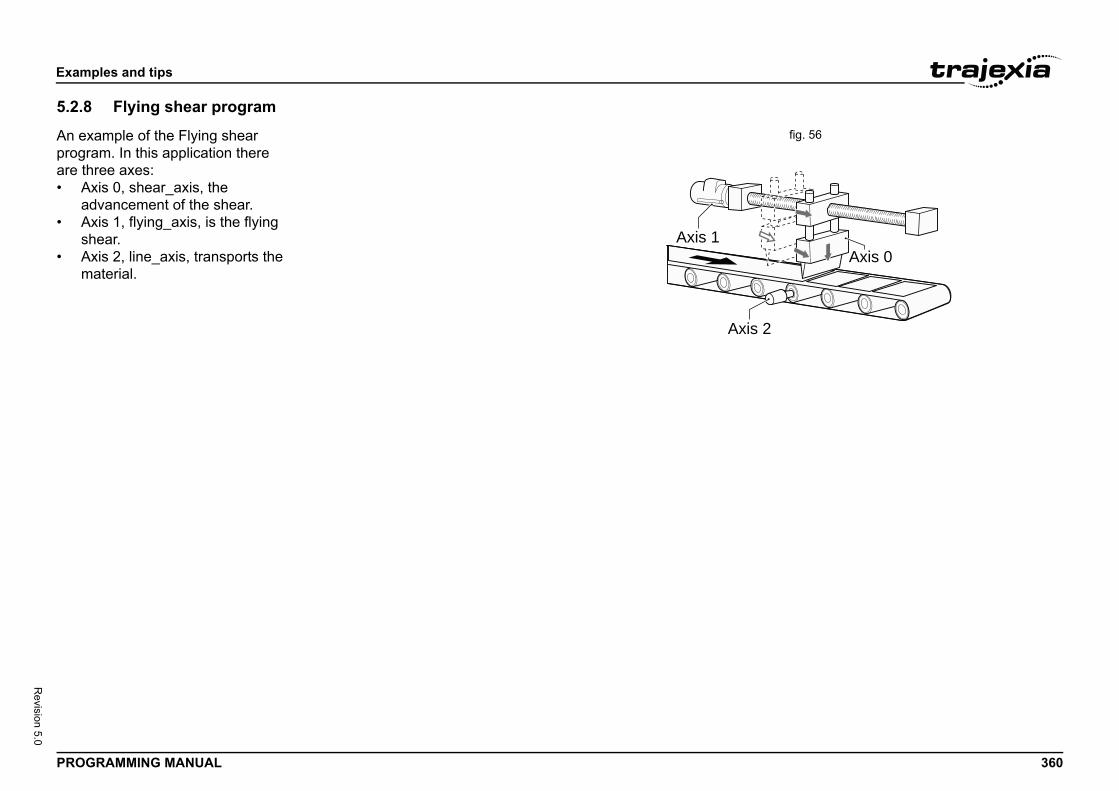
Exam
PROG 360
Revision 5.0
5.2.8fig. 56An ex
prograre th• A
a• A
sh• A
mAxis 0
2
ples and tips
RAMMING MANUAL
Flying shear program
ample of the Flying shear am. In this application there ree axes:xis 0, shear_axis, the dvancement of the shear.xis 1, flying_axis, is the flying ear.
xis 2, line_axis, transports the aterial.
Axis 1
Axis
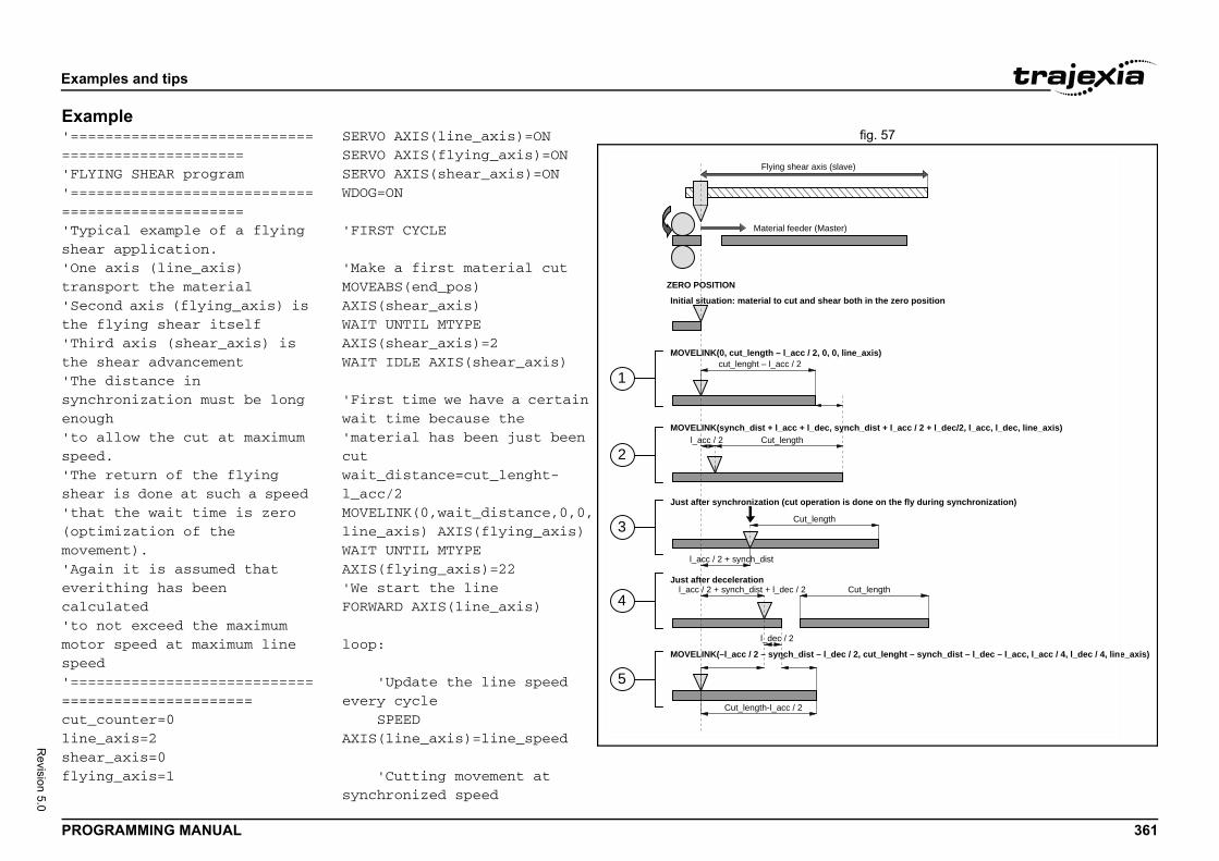
Exam
PROG 361
Revision 5.0
Examfig. 57'====
====='FLYI'========='Typishear'One trans'Secothe f'Thirthe s'The synchenoug'to aspeed'The shear'that(optimovem'Agaievericalcu'to nmotorspeed'=========cut_cline_shearflyin
(slave)
aster)
ear both in the zero position
tion is done on the fly during synchronization)
gth
, 0, line_axis)
c, synch_dist + l_acc / 2 + l_dec/2, l_acc, l_dec, line_axis)
l_dec / 2, cut_lenght – synch_dist – l_dec – l_acc, l_acc / 4, l_dec / 4, line_axis)
Cut_length
ples and tips
RAMMING MANUAL
ple========================================NG SHEAR program========================================cal example of a flying application.axis (line_axis) port the materialnd axis (flying_axis) is lying shear itselfd axis (shear_axis) is hear advancementdistance in ronization must be long hllow the cut at maximum .return of the flying is done at such a speed the wait time is zero mization of the ent).n it is assumed that thing has been lated ot exceed the maximum speed at maximum line
=========================================ounter=0axis=2_axis=0g_axis=1
SERVO AXIS(line_axis)=ONSERVO AXIS(flying_axis)=ONSERVO AXIS(shear_axis)=ONWDOG=ON
'FIRST CYCLE
'Make a first material cutMOVEABS(end_pos) AXIS(shear_axis)WAIT UNTIL MTYPE AXIS(shear_axis)=2WAIT IDLE AXIS(shear_axis)
'First time we have a certain wait time because the'material has been just been cutwait_distance=cut_lenght-l_acc/2MOVELINK(0,wait_distance,0,0,line_axis) AXIS(flying_axis)WAIT UNTIL MTYPE AXIS(flying_axis)=22'We start the lineFORWARD AXIS(line_axis)
loop:
'Update the line speed every cycle SPEED AXIS(line_axis)=line_speed
'Cutting movement at synchronized speed
1
2
3
4
5
Flying shear axis
Material feeder (M
ZERO POSITION
Initial situation: material to cut and sh
Just after synchronization (cut opera
Cut_len
MOVELINK(0, cut_length – l_acc / 2, 0cut_lenght – l_acc / 2
Cut_lengthMOVELINK(synch_dist + l_acc + l_de
l_acc / 2
l_acc / 2 + synch_dist
Just after deceleration
Cut_length-l_acc / 2
MOVELINK(–l_acc / 2 – synch_dist –
l_dec / 2
l_acc / 2 + synch_dist + l_dec / 2
Exam
PROG 362
Revision 5.0
line_ec shear2+l_d MOVEL_acc,AXIS( WAXIS(
'it isthe l ' SAXIS( MAXIS( MAXIS( WAXIS( ' WAXIS( SAXIS(
cut_c
'with
ples and tips
RAMMING MANUAL
cut=synch_dist+l_acc+l_d
_cut=synch_dist+l_acc/ec/2
INK(shear_cut,line_cut,ll_dec,line_axis) flying_axis)AIT UNTIL MPOS flying_axis)>l_acc/2
Activate the shear when in synchronization with ineSlow speed to cutPEED shear_axis)=cut_speedOVEABS(end_pos) shear_axis)OVEABS(0) shear_axis)AIT UNTIL NTYPE shear_axis)=2Fast speed to returnAIT LOADED shear_axis)PEED shear_axis)=return_speed
ounter=cut_counter+1inch
Return back synchronized the master in such a way
'that there is no wait time line_back=cut_length-synch_dist-l_dec-l_acc shear_cut=l_acc/2+synch_dist+l_dec/2) MOVELINK(-shear_cut,line_back,l_acc/4,l_dec/4,line_axis) AXIS(flying_axis)
GOTO loop
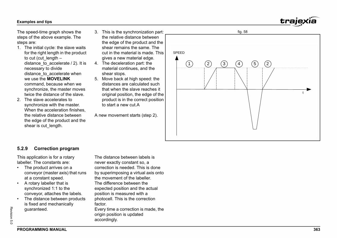
Exam
PROG 363
Revision 5.0
fig. 58The sstepssteps1. T
fotodndwcosytw
2. TsyWththsh
5.2.9
This alabell• T
coa
• Asyco
• Tisg
t
24 5
ples and tips
RAMMING MANUAL
peed-time graph shows the of the above example. The are:he initial cycle: the slave waits r the right length in the product cut (cut_length –
istance_to_accelerate / 2). It is ecessary to divide istance_to_accelerate when e use the MOVELINK mmand, because when we nchronize, the master moves ice the distance of the slave.
he slave accelerates to nchronize with the master. hen the acceleration finishes, e relative distance between e edge of the product and the ear is cut_length.
3. This is the synchronization part: the relative distance between the edge of the product and the shear remains the same. The cut in the material is made. This gives a new material edge.
4. The deceleration part: the material continues, and the shear stops.
5. Move back at high speed: the distances are calculated such that when the slave reaches it original position, the edge of the product is in the correct position to start a new cut.A
A new movement starts (step 2).
Correction program
pplication is for a rotary er. The constants are:he product arrives on a nveyor (master axis) that runs
t a constant speed. rotary labeller that is nchronized 1:1 to the nveyor, attaches the labels.
he distance between products fixed and mechanically uaranteed.
The distance between labels is never exactly constant so, a correction is needed. This is done by superimposing a virtual axis onto the movement of the labeller.The difference between the expected position and the actual position is measured with a photocell. This is the correction factor. Every time a correction is made, the origin position is updated accordingly.
SPEED
1 2 3
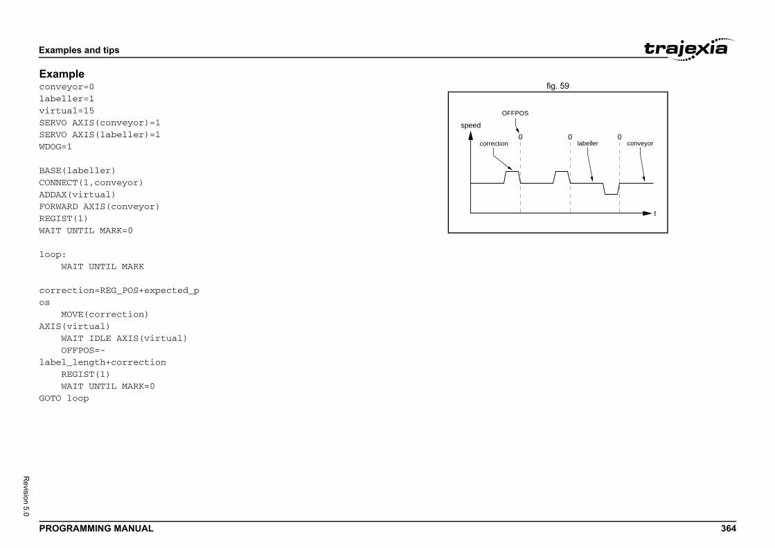
Exam
PROG 364
Revision 5.0
Examfig. 59conve
labelvirtuSERVOSERVOWDOG=
BASE(CONNEADDAXFORWAREGISWAIT
loop: W correos MAXIS( W Olabel R WGOTO
t
0 0
S
labeller conveyor
ples and tips
RAMMING MANUAL
pleyor=0ler=1al=15 AXIS(conveyor)=1 AXIS(labeller)=11
labeller)CT(1,conveyor)(virtual)RD AXIS(conveyor)T(1)UNTIL MARK=0
AIT UNTIL MARK
ction=REG_POS+expected_p
OVE(correction) virtual)AIT IDLE AXIS(virtual)FFPOS=-_length+correctionEGIST(1)AIT UNTIL MARK=0loop
speed0
OFFPO
correction
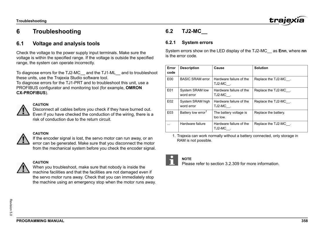
Troub
PROG 358
Revision 5.0
6
6.1Checvoltagrange
To diatheseTo diaPROFCX-P
ED display of the TJ2-MC__ as Enn, where nn
se Solution
dware failure of the -MC__.
Replace the TJ2-MC__.
dware failure of the -MC__.
Replace the TJ2-MC__.
dware failure of the -MC__.
Replace the TJ2-MC__.
lly without a battery connected, only storage in
battery voltage is low.
Replace the battery.
dware failure of the -MC__.
Replace the TJ2-MC__.
on 3.2.309 for more information.
leshooting
RAMMING MANUAL
Troubleshooting
Voltage and analysis toolsk the voltage to the power supply input terminals. Make sure the e is within the specified range. If the voltage is outside the specified , the system can operate incorrectly.
gnose errors for the TJ2-MC__ and the TJ1-ML__ and to troubleshoot units, use the Trajexia Studio software tool.gnose errors for the TJ1-PRT and to troubleshoot this unit, use a IBUS configurator and monitoring tool (for example, OMRON
ROFIBUS).
6.2 TJ2-MC__
6.2.1 System errors
System errors show on the Lis the error code./i
CAUTIONDisconnect all cables before you check if they have burned out. Even if you have checked the conduction of the wiring, there is a risk of conduction due to the return circuit.
CAUTIONIf the encoder signal is lost, the servo motor can run away, or an error can be generated. Make sure that you disconnect the motor from the mechanical system before you check the encoder signal.
CAUTIONWhen you troubleshoot, make sure that nobody is inside the machine facilities and that the facilities are not damaged even if the servo motor runs away. Check that you can immediately stop the machine using an emergency stop when the motor runs away.
Error code
Description Cau
E00 BASIC SRAM error HarTJ2
E01 System SRAM low word error
HarTJ2
E02 System SRAM high word error
HarTJ2
E03 Battery low error1
1. Trajexia can work normaRAM is not possible.
Thetoo
... Hardware failure HarTJ2
NOTEPlease refer to secti
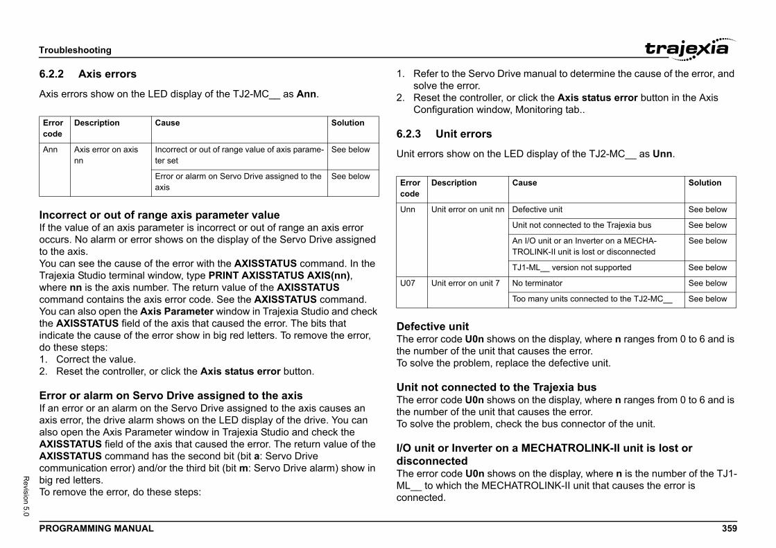
Troub
PROG 359
Revision 5.0
6.2.2
Axis e/i
IncoIf theoccurto theYou cTrajewherecommYou cthe Aindicado th1. C2. R
ErroIf an axis ealso oAXISAXIScommbig reTo rem
anual to determine the cause of the error, and
ick the Axis status error button in the Axis nitoring tab..
display of the TJ2-MC__ as Unn.
the display, where n ranges from 0 to 6 and is uses the error. the defective unit.
Trajexia bus the display, where n ranges from 0 to 6 and is uses the error.
the bus connector of the unit.
ECHATROLINK-II unit is lost or
n the display, where n is the number of the TJ1-OLINK-II unit that causes the error is
Errorcode
Ann
se Solution
ective unit See below
t not connected to the Trajexia bus See below
I/O unit or an Inverter on a MECHA-LINK-II unit is lost or disconnected
See below
-ML__ version not supported See below
terminator See below
many units connected to the TJ2-MC__ See below
leshooting
RAMMING MANUAL
Axis errors
rrors show on the LED display of the TJ2-MC__ as Ann.
rrect or out of range axis parameter value value of an axis parameter is incorrect or out of range an axis error s. No alarm or error shows on the display of the Servo Drive assigned axis.an see the cause of the error with the AXISSTATUS command. In the xia Studio terminal window, type PRINT AXISSTATUS AXIS(nn), nn is the axis number. The return value of the AXISSTATUS and contains the axis error code. See the AXISSTATUS command.
an also open the Axis Parameter window in Trajexia Studio and check XISSTATUS field of the axis that caused the error. The bits that te the cause of the error show in big red letters. To remove the error,
ese steps:orrect the value.eset the controller, or click the Axis status error button.
r or alarm on Servo Drive assigned to the axiserror or an alarm on the Servo Drive assigned to the axis causes an rror, the drive alarm shows on the LED display of the drive. You can pen the Axis Parameter window in Trajexia Studio and check the
STATUS field of the axis that caused the error. The return value of the STATUS command has the second bit (bit a: Servo Drive unication error) and/or the third bit (bit m: Servo Drive alarm) show in d letters.ove the error, do these steps:
1. Refer to the Servo Drive msolve the error.
2. Reset the controller, or clConfiguration window, Mo
6.2.3 Unit errors
Unit errors show on the LED /i
Defective unitThe error code U0n shows onthe number of the unit that caTo solve the problem, replace
Unit not connected to theThe error code U0n shows onthe number of the unit that caTo solve the problem, check
I/O unit or Inverter on a MdisconnectedThe error code U0n shows oML__ to which the MECHATRconnected.
Description Cause Solution
Axis error on axis nn
Incorrect or out of range value of axis parame-ter set
See below
Error or alarm on Servo Drive assigned to the axis
See belowError code
Description Cau
Unn Unit error on unit nn Def
Uni
An TRO
TJ1
U07 Unit error on unit 7 No
Too
Troub
PROG 360
Revision 5.0
You cenablTo disStudi
To enStudi
To seTraje
To cle
• R• T
wwuis
If youavailain theTJ1-M
TJ1-TJ2-MFPGAin theTJ1-M
No teThe eTo sotermin
dn the display.the number of connected units. No more than
ors
the LED display of the TJ2-MC__ as Cnn.
ry
y, do these steps:pply Unit is set to on for at least five minutes. If cks up the memory of the TJ2-MC__ while the s not fully charged, and you can lose data in
e battery compartment away from the unit to ment.es to pull out the old battery.
Solution
m has too many units of the e, and it does not adhere to for adding units to a system
Change the system so that it adheres to the rules for adding units to a system. See the Hard-ware Reference manual.
connected too many MECHA--II stations to the TJ1-ML__
too many axes in the system
too many non-axis MECHA--II stations in the system
FSET is non-zero for a unit rting axes (e.g. TJ1-PRT)
Change AXIS_OFFSET to 0 for this unit.
PERIOD is not set to 500 in ion with TJ2-KS02 and at least ected Servo Drive.
Change the SERVO_PERIOD to 500.
leshooting
RAMMING MANUAL
an set system flags to enable and disable these errors. The errors are ed by default.able the errors, type COORDINATOR_DATA(7,1) in the Trajexia
o terminal window.
able the errors, type COORDINATOR_DATA(7,0) in the Trajexia o terminal window.
e the current setting, type PRINT COORDINATOR_DATA(7) in the xia Studio terminal window.
ar the error after repair do these steps:
econnect the lost MECHATROLINK-II I/O unit or Inverter.ype MECHATROLINK(n, 5, station, -1) in the Trajexia Studio terminal indow:here n is the number of the TJ1-ML__ to which the MECHATROLINK-II nit affected, and station is the MECHATROLINK-II device number that lost.
want to use the system without the lost device, you can reconnect all ble devices on the TJ1-ML__. To do this, type MECHATROLINK(n, 0) Trajexia Studio terminal window, where n is the number of the L__ that reports the error.
ML__ version not supportedC__ requires TJ1-ML__ units with a minimum FPGA version 18. The version can be checked by typing PRINT FPGA_VERSION SLOT(x)
Trajexia Studio terminal window. Replace x with the position of the L__ unit, starting from 0.
rminatorrror code U07 shows on the display.lve the problem, check the terminator connection or replace the ator if it is defective.
Too many units connecteThe error code U07 shows oTo solve the problem, check 7 units are supported.
6.2.4 Configuration err
Configuration errors show on/i
6.2.5 Replace the batte
To replace the backup batter1. Make sure the Power Su
not, the capacitor that babattery is not connected imemory.
2. Pull the top of the lid of thopen the battery compart
3. Pull the red and white wir
Error code
Description Cause
Cnn Configuration error caused by unit nn
The systesame typthe rules
You haveTROLINK
There are
There areTROLINK
AXIS_OFnot suppo
SERVO_combinatone conn
Troub
PROG 361
Revision 5.0
4. Md
5. D6. A7. In8. C
6.3
6.3.1/i
ication problems
Indic
No LEor flas
ERH
ERC
Solution
S configuration is e is no communica-aster.
• Check that the TJ1-PRT has the same station address as in the configuration of the master.
• Check that no station address is used twice.
S wiring is not cor- • Check that the correct pins of the CN1 connector are con-nected.
• Check that there are no short circuits or line interruption.
• Check that you use the cor-rect cable type.
• Check that the stub lines are not too long.
properly terminated S network.
Terminate the PROFIBUS network at the appropriate places.
S master unit is Replace the master unit.
is defective. Replace the TJ1-PRT.
S configuration is e is no communica-aster.
• Check that you use the cor-rect GSD file in the master.
• Check the configuration and the parameter data of the slave.
• Check that the network has been configured to communi-cate at the baud rate sup-ported by the TJ1-PRT.
selected configura-e slave.
Check the configuration at the master.
is defective. Replace the TJ1-PRT.
leshooting
RAMMING MANUAL
ake sure you complete the next 2 steps within 30 seconds to prevent ata loss in the RAM memory.isconnect the wires from the old battery.ttach the wires to the new battery.sert the new battery into the battery compartment.lose the lid of the battery compartment.
TJ1-PRT
System errors
6.3.2 I/O data commun/i
ation Problem Solution
Ds are on hing
The power is off. Turn the power on.
The TJ1-PRT is defective. Replace the TJ1-PRT.
LED is on Communication failure between TJ2-MC__ and TJ1-PRT.
Reset the TJ2-MC__. If this does not help, replace the TJ2-MC__.
LED is on Unit error. The TJ1-PRT is defec-tive.
Replace the TJ1-PRT.
Indication Problem
COMM LED is off and BF LED is on
The PROFIBUincorrect, thertion with the m
The PROFIBUrect.
You have not the PROFIBU
The PROFIBUdefective.
The TJ1-PRT
COMM LED is off and BF LED is flashing
The PROFIBUincorrect, thertion with the m
You have not tion data for th
The TJ1-PRT
Troub
PROG 362
Revision 5.0
6.4
6.4.1/i
6.4.2/i
ication problems
Indic
No LEor flas
ERH
ERC
Indic
NOK and N
NOK LED i
Solution
ff. Turn the power on.
T is defective. Replace the TJ1-CORT.
n failure between U and TJ1-CORT.
Reset the TJ2-MC__ CPU. If this does not help, replace the CPU.
TJ1-CORT is Replace the TJ1-CORT.
Solution
r or fatal error Restart the unit. If the problem persists, replace the TJ1-CORT.
ration. Check downloaded configuration. If necessary re-download it.
warning limit ible causes:nodes on the net-
ermination incor-
ables installed
Check the network cabling and network nodes.
ent occurred.eartbeat message ode was not
n the timeout inter-
Check the node, which was expected to send the heartbeat message.
leshooting
RAMMING MANUAL
TJ1-DRT
System errors
I/O data communication problems
6.5 TJ1-CORT
6.5.1 System errors/i
6.5.2 I/O data commun/i
ation Problem Solution
Ds are on hing
The power is off. Turn the power on.
The TJ1-DRT is defective. Replace the TJ1-DRT.
LED is on Communication failure between TJ2-MC__ and TJ1-DRT.
Reset the TJ2-MC__. If this does not help, replace the TJ2-MC__.
LED is on Unit error. The TJ1-DRT is defec-tive.
Replace the TJ1-DRT.
ation Problem Solution
is flashing F LED is off
The DeviceNet master is not com-municating with the TJ1-DRT.
• Configure and start the DeviceNet master.
off and NF s on
The node address duplication error.
• Check node address.
Network cable error. • Check network cables.
Indication Problem
No LEDs are on or flashing
The power is o
The TJ1-COR
ERH LED is on CommunicatioTJ2-MC__ CP
ERC LED is on Unit error. Thedefective.
Indication Problem
NWST is off A start-up errooccurred.
BF flashing Invalid configu
BF flashingsingle flash
Error counter reached. Poss• No other
work.• Network t
rect.• Network c
incorrect.
BF flashingdouble flash
A heartbeat evAn expected hfrom another nreceived withival.
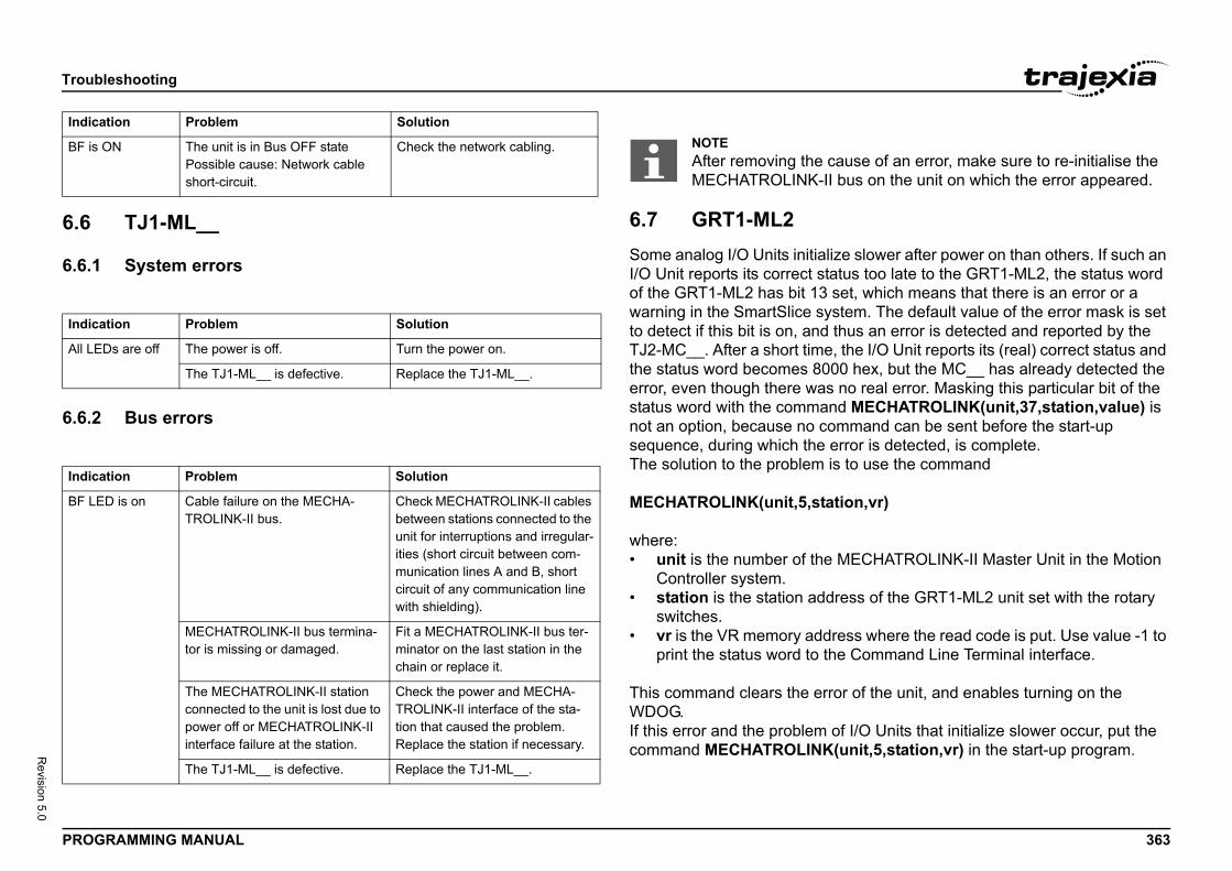
Troub
PROG 363
Revision 5.0
6.6
6.6.1/i
6.6.2/i
ze slower after power on than others. If such an tus too late to the GRT1-ML2, the status word
set, which means that there is an error or a stem. The default value of the error mask is set thus an error is detected and reported by the , the I/O Unit reports its (real) correct status and 0 hex, but the MC__ has already detected the
no real error. Masking this particular bit of the d MECHATROLINK(unit,37,station,value) is mmand can be sent before the start-up rror is detected, is complete.
s to use the command
tion,vr)
MECHATROLINK-II Master Unit in the Motion
ress of the GRT1-ML2 unit set with the rotary
ess where the read code is put. Use value -1 to e Command Line Terminal interface.
or of the unit, and enables turning on the
f I/O Units that initialize slower occur, put the (unit,5,station,vr) in the start-up program.
BF is
Indic
All LE
Indic
BF LE
Indic
ause of an error, make sure to re-initialise the bus on the unit on which the error appeared.
leshooting
RAMMING MANUAL
TJ1-ML__
System errors
Bus errors
6.7 GRT1-ML2Some analog I/O Units initialiI/O Unit reports its correct staof the GRT1-ML2 has bit 13 warning in the SmartSlice syto detect if this bit is on, and TJ2-MC__. After a short timethe status word becomes 800error, even though there wasstatus word with the commannot an option, because no cosequence, during which the eThe solution to the problem i
MECHATROLINK(unit,5,sta
where:• unit is the number of the
Controller system.• station is the station add
switches.• vr is the VR memory addr
print the status word to th
This command clears the errWDOG.If this error and the problem ocommand MECHATROLINK
ON The unit is in Bus OFF statePossible cause: Network cable short-circuit.
Check the network cabling.
ation Problem Solution
Ds are off The power is off. Turn the power on.
The TJ1-ML__ is defective. Replace the TJ1-ML__.
ation Problem Solution
D is on Cable failure on the MECHA-TROLINK-II bus.
Check MECHATROLINK-II cables between stations connected to the unit for interruptions and irregular-ities (short circuit between com-munication lines A and B, short circuit of any communication line with shielding).
MECHATROLINK-II bus termina-tor is missing or damaged.
Fit a MECHATROLINK-II bus ter-minator on the last station in the chain or replace it.
The MECHATROLINK-II station connected to the unit is lost due to power off or MECHATROLINK-II interface failure at the station.
Check the power and MECHA-TROLINK-II interface of the sta-tion that caused the problem. Replace the station if necessary.
The TJ1-ML__ is defective. Replace the TJ1-ML__.
ation Problem SolutionNOTEAfter removing the cMECHATROLINK-II
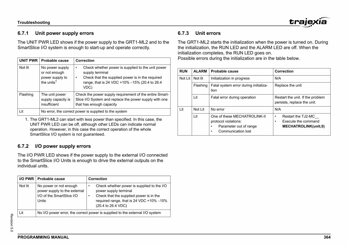
Troub
PROG 364
Revision 5.0
6.7.1
The USmar/i
6.7.2
The Ito theindivi/i
tialization when the power is turned on. During D and the ALARM LED are off. When the UN LED goes on.tialization are in the table below.UNIT
Not li
1.
Flash
Lit
I/O PW
Not li
Lit
e Correction
progress N/A
rror during initializa- Replace the unit
ng operation Restart the unit. If the problem persists, replace the unit.
N/A
ECHATROLINK-II ns: out of rangeation lost
• Restart the TJ2-MC__• Execute the command
MECHATROLINK(unit,0)
leshooting
RAMMING MANUAL
Unit power supply errors
NIT PWR LED shows if the power supply to the GRT1-ML2 and to the tSlice I/O system is enough to start-up and operate correctly.
I/O power supply errors
/O PWR LED shows if the power supply to the external I/O connected SmartSlice I/O Units is enough to drive the external outputs on the dual units.
6.7.3 Unit errors
The GRT1-ML2 starts the inithe initialization, the RUN LEinitialization completes, the RPossible errors during the ini/i
PWR Probable cause Correction
t No power supply or not enough power supply to the units1
The GRT1-ML2 can start with less power than specified. In this case, the UNIT PWR LED can be off, although other LEDs can indicate normal operation. However, in this case the correct operation of the whole SmartSlice I/O system is not guaranteed.
• Check whether power is supplied to the unit power supply terminal
• Check that the supplied power is in the required range, that is 24 VDC +10% −15% (20.4 to 26.4 VDC)
ing The unit power supply capacity is insufficient
Check the power supply requirement of the entire Smart-Slice I/O System and replace the power supply with one that has enough capacity
No error, the correct power is supplied to the system
R Probable cause Correction
t No power or not enough power supply to the external I/O of the SmartSlice I/O Units
• Check whether power is supplied to the I/O power supply terminal
• Check that the supplied power is in the required range, that is 24 VDC +10% −15% (20.4 to 26.4 VDC)
No I/O power error, the correct power is supplied to the external I/O system
RUN ALARM Probable caus
Not Lit Not lit Initialization in
Flashing Fatal system etion
Lit Fatal error duri
Lit Not Lit No error
Lit One of these Mprotocol violatio• Parameter• Communic
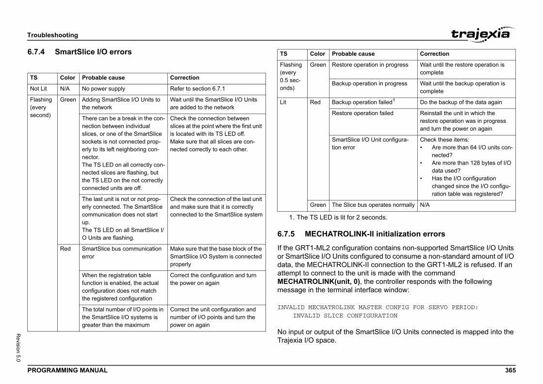
Troub
PROG 365
Revision 5.0
6.7.4/i
-II initialization errors
n contains non-supported SmartSlice I/O Units ured to consume a non-standard amount of I/O
I connection to the GRT1-ML2 is refused. If an t is made with the command e controller responds with the following face window:
TER CONFIG FOR SERVO PERIOD:URATION
rtSlice I/O Units connected is mapped into the
TS
Not L
Flash(eversecon
tion in progress Wait until the restore operation is complete
tion in progress Wait until the backup operation is complete
tion failed1 Do the backup of the data again
tion failed Reinstall the unit in which the restore operation was in progress and turn the power on again
Unit configura- Check these items:• Are more than 64 I/O units con-
nected?• Are more than 128 bytes of I/O
data used?• Has the I/O configuration
changed since the I/O configu-ration table was registered?
operates normally N/A
conds.
se Correction
leshooting
RAMMING MANUAL
SmartSlice I/O errors
6.7.5 MECHATROLINK
If the GRT1-ML2 configuratioor SmartSlice I/O Units configdata, the MECHATROLINK-Iattempt to connect to the uniMECHATROLINK(unit, 0), thmessage in the terminal inter
INVALID MECHATROLINK MAS INVALID SLICE CONFIG
No input or output of the SmaTrajexia I/O space.
Color Probable cause Correction
it N/A No power supply Refer to section 6.7.1
ing y d)
Green Adding SmartSlice I/O Units to the network
Wait until the SmartSlice I/O Units are added to the network
There can be a break in the con-nection between individual slices, or one of the SmartSlice sockets is not connected prop-erly to its left neighboring con-nector.The TS LED on all correctly con-nected slices are flashing, but the TS LED on the not correctly connected units are off.
Check the connection between slices at the point where the first unit is located with its TS LED off.Make sure that all slices are con-nected correctly to each other.
The last unit is not or not prop-erly connected. The SmartSlice communication does not start up.The TS LED on all SmartSlice I/O Units are flashing.
Check the connection of the last unit and make sure that it is correctly connected to the SmartSlice system
Red SmartSlice bus communication error
Make sure that the base block of the SmartSlice I/O System is connected properly
When the registration table function is enabled, the actual configuration does not match the registered configuration
Correct the configuration and turn the power on again
The total number of I/O points in the SmartSlice I/O systems is greater than the maximum
Correct the unit configuration and number of I/O points and turn the power on again
Flashing (every 0.5 sec-onds)
Green Restore opera
Backup opera
Lit Red Backup opera
Restore opera
SmartSlice I/Otion error
Green The Slice bus
1. The TS LED is lit for 2 se
TS Color Probable cau
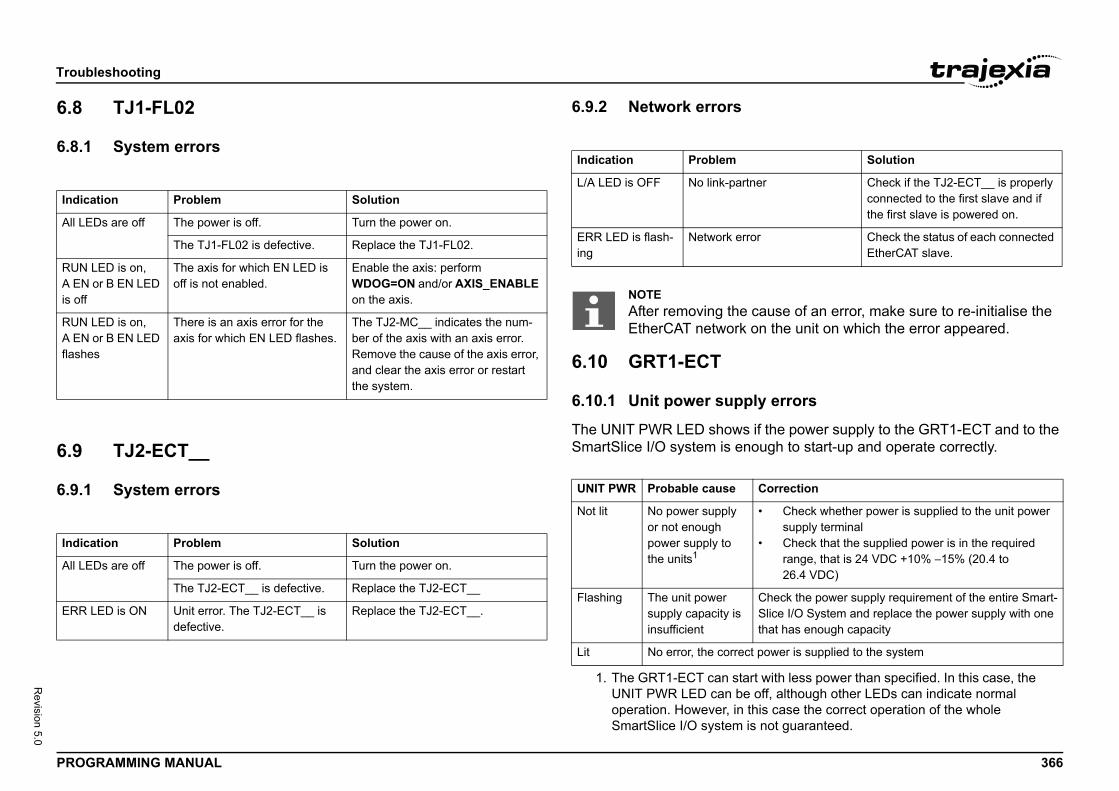
Troub
PROG 366
Revision 5.0
6.8
6.8.1/i
6.9
6.9.1/i
y errors
f the power supply to the GRT1-ECT and to the ugh to start-up and operate correctly.
Indic
All LE
RUN A ENis off
RUN A ENflashe
Indic
All LE
ERR
Solution
er Check if the TJ2-ECT__ is properly connected to the first slave and if the first slave is powered on.
r Check the status of each connected EtherCAT slave.
ause of an error, make sure to re-initialise the n the unit on which the error appeared.
Correction
with less power than specified. In this case, the ff, although other LEDs can indicate normal is case the correct operation of the whole not guaranteed.
• Check whether power is supplied to the unit power supply terminal
• Check that the supplied power is in the required range, that is 24 VDC +10% −15% (20.4 to 26.4 VDC)
Check the power supply requirement of the entire Smart-Slice I/O System and replace the power supply with one that has enough capacity
power is supplied to the system
leshooting
RAMMING MANUAL
TJ1-FL02
System errors
TJ2-ECT__
System errors
6.9.2 Network errors/i
6.10 GRT1-ECT
6.10.1 Unit power suppl
The UNIT PWR LED shows iSmartSlice I/O system is eno/i
ation Problem Solution
Ds are off The power is off. Turn the power on.
The TJ1-FL02 is defective. Replace the TJ1-FL02.
LED is on, or B EN LED
The axis for which EN LED is off is not enabled.
Enable the axis: perform WDOG=ON and/or AXIS_ENABLE on the axis.
LED is on, or B EN LED s
There is an axis error for the axis for which EN LED flashes.
The TJ2-MC__ indicates the num-ber of the axis with an axis error. Remove the cause of the axis error, and clear the axis error or restart the system.
ation Problem Solution
Ds are off The power is off. Turn the power on.
The TJ2-ECT__ is defective. Replace the TJ2-ECT__
LED is ON Unit error. The TJ2-ECT__ is defective.
Replace the TJ2-ECT__.
Indication Problem
L/A LED is OFF No link-partn
ERR LED is flash-ing
Network erro
NOTEAfter removing the cEtherCAT network o
UNIT PWR Probable cause
Not lit No power supply or not enough power supply to the units1
1. The GRT1-ECT can startUNIT PWR LED can be ooperation. However, in thSmartSlice I/O system is
Flashing The unit power supply capacity is insufficient
Lit No error, the correct
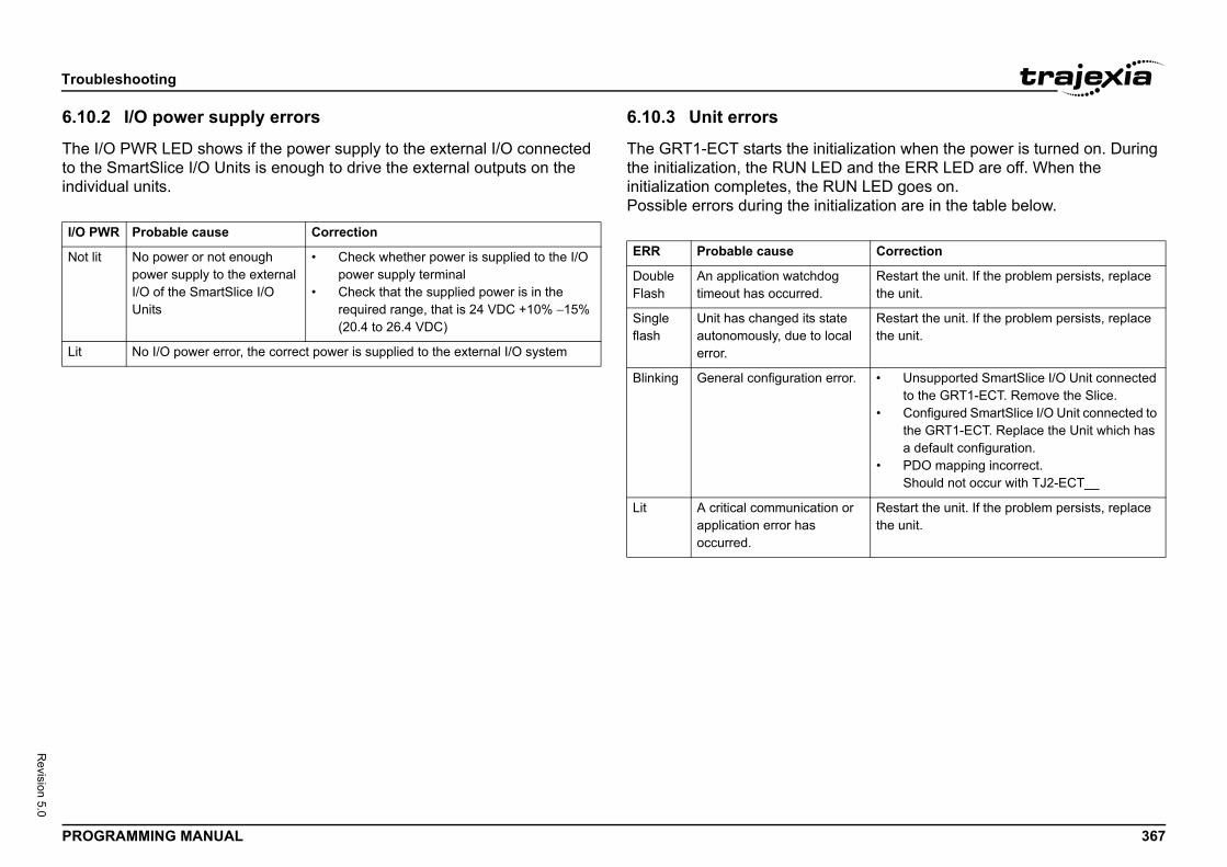
Troub
PROG 367
Revision 5.0
6.10.
The Ito theindivi/i
tialization when the power is turned on. During D and the ERR LED are off. When the UN LED goes on.tialization are in the table below.
I/O PW
Not li
Lit
Correction
g Restart the unit. If the problem persists, replace the unit.
ate cal
Restart the unit. If the problem persists, replace the unit.
rror. • Unsupported SmartSlice I/O Unit connected to the GRT1-ECT. Remove the Slice.
• Configured SmartSlice I/O Unit connected to the GRT1-ECT. Replace the Unit which has a default configuration.
• PDO mapping incorrect.Should not occur with TJ2-ECT__
n or Restart the unit. If the problem persists, replace the unit.
leshooting
RAMMING MANUAL
2 I/O power supply errors
/O PWR LED shows if the power supply to the external I/O connected SmartSlice I/O Units is enough to drive the external outputs on the dual units.
6.10.3 Unit errors
The GRT1-ECT starts the inithe initialization, the RUN LEinitialization completes, the RPossible errors during the ini/iR Probable cause Correction
t No power or not enough power supply to the external I/O of the SmartSlice I/O Units
• Check whether power is supplied to the I/O power supply terminal
• Check that the supplied power is in the required range, that is 24 VDC +10% −15% (20.4 to 26.4 VDC)
No I/O power error, the correct power is supplied to the external I/O system
ERR Probable cause
Double Flash
An application watchdotimeout has occurred.
Single flash
Unit has changed its stautonomously, due to loerror.
Blinking General configuration e
Lit A critical communicatioapplication error has occurred.
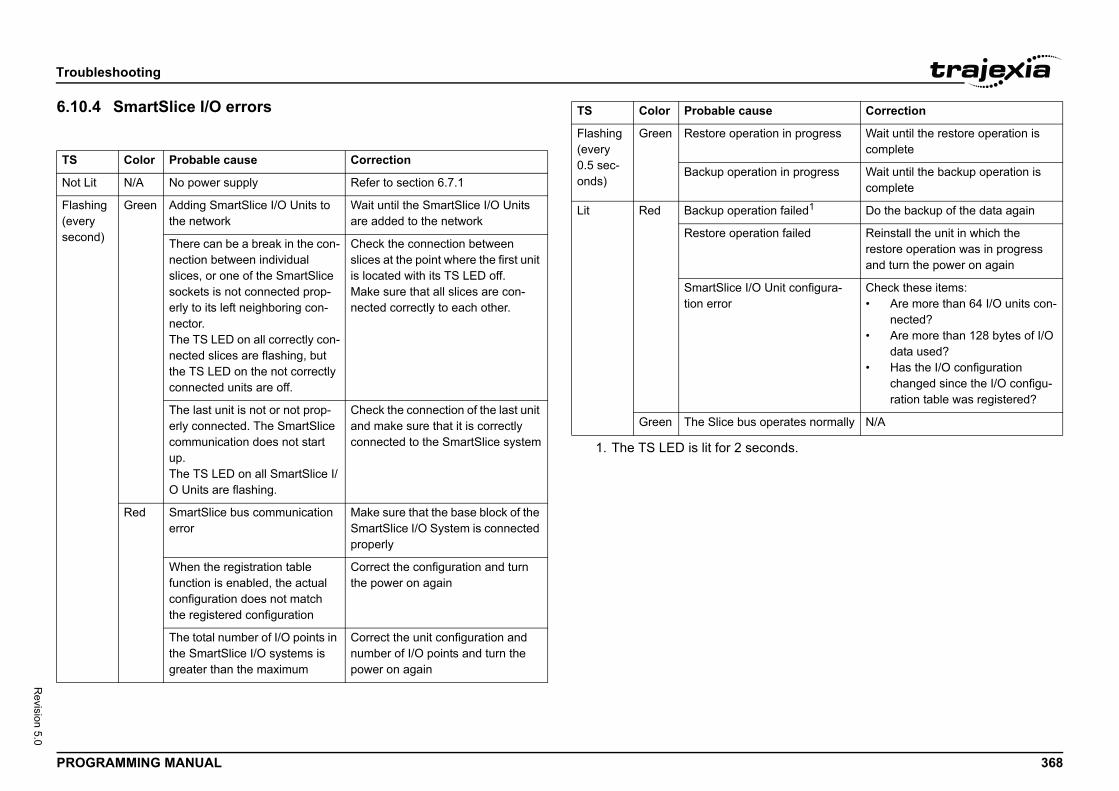
Troub
PROG 368
Revision 5.0
6.10./i
TS
Not L
Flash(eversecon
tion in progress Wait until the restore operation is complete
tion in progress Wait until the backup operation is complete
tion failed1 Do the backup of the data again
tion failed Reinstall the unit in which the restore operation was in progress and turn the power on again
Unit configura- Check these items:• Are more than 64 I/O units con-
nected?• Are more than 128 bytes of I/O
data used?• Has the I/O configuration
changed since the I/O configu-ration table was registered?
operates normally N/A
conds.
se Correction
leshooting
RAMMING MANUAL
4 SmartSlice I/O errors
Color Probable cause Correction
it N/A No power supply Refer to section 6.7.1
ing y d)
Green Adding SmartSlice I/O Units to the network
Wait until the SmartSlice I/O Units are added to the network
There can be a break in the con-nection between individual slices, or one of the SmartSlice sockets is not connected prop-erly to its left neighboring con-nector.The TS LED on all correctly con-nected slices are flashing, but the TS LED on the not correctly connected units are off.
Check the connection between slices at the point where the first unit is located with its TS LED off.Make sure that all slices are con-nected correctly to each other.
The last unit is not or not prop-erly connected. The SmartSlice communication does not start up.The TS LED on all SmartSlice I/O Units are flashing.
Check the connection of the last unit and make sure that it is correctly connected to the SmartSlice system
Red SmartSlice bus communication error
Make sure that the base block of the SmartSlice I/O System is connected properly
When the registration table function is enabled, the actual configuration does not match the registered configuration
Correct the configuration and turn the power on again
The total number of I/O points in the SmartSlice I/O systems is greater than the maximum
Correct the unit configuration and number of I/O points and turn the power on again
Flashing (every 0.5 sec-onds)
Green Restore opera
Backup opera
Lit Red Backup opera
Restore opera
SmartSlice I/Otion error
Green The Slice bus
1. The TS LED is lit for 2 se
TS Color Probable cau
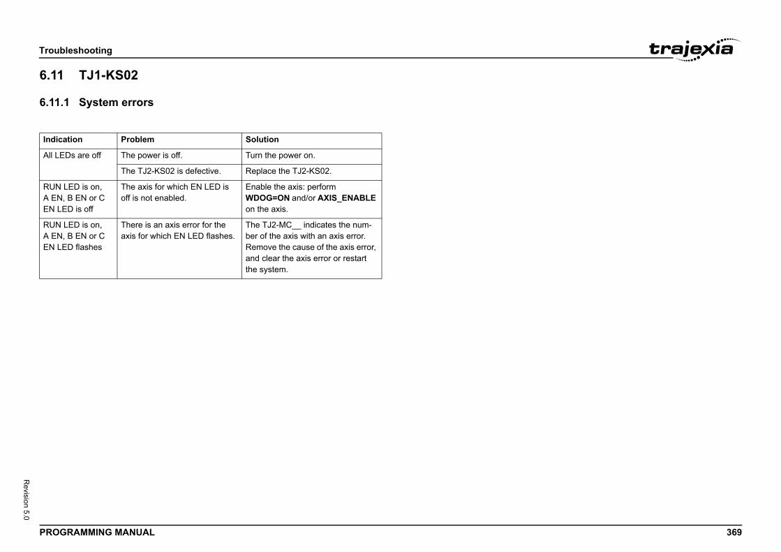
Troub
PROG 369
Revision 5.0
6.11
6.11./i
Indic
All LE
RUN A ENEN LE
RUN A ENEN LE
leshooting
RAMMING MANUAL
TJ1-KS02
1 System errors
ation Problem Solution
Ds are off The power is off. Turn the power on.
The TJ2-KS02 is defective. Replace the TJ2-KS02.
LED is on,, B EN or C D is off
The axis for which EN LED is off is not enabled.
Enable the axis: perform WDOG=ON and/or AXIS_ENABLE on the axis.
LED is on,, B EN or C D flashes
There is an axis error for the axis for which EN LED flashes.
The TJ2-MC__ indicates the num-ber of the axis with an axis error. Remove the cause of the axis error, and clear the axis error or restart the system.
GRT1
PROG 370
Revision 5.0
AThis abetweinformcontroIn this• A• T• T
• A
A.1
A.1.1
There• T• T
-ML2 timing
RAMMING MANUAL
GRT1-ML2 timingppendix describes the I/O timing issues for the communication en the TJ2-MC__, the GRT1-ML2 and the SmartSlice I/O Units. The ation in this section is useful for planning operations that require strict l of the I/O timing. section, the following is assumed:
ll required slaves participate in the communication.he TJ2-MC__ and the GRT-ML2 have no error indications.he I/O configuration is properly registered.
ll filter functions in the SmartSlice I/O Units are disabled.
Timing concepts
Refresh cycles
are two refresh cycles involved in the timing issues:he refresh cycle between the TJ2-MC__ and the GRT1-ML2he refresh cycle between the GRT1-ML2 and the SmartSlice I/O Units.
NOTETo register the I/O configuration, use the REGS dipswitch. See the Trajexia Hardware Reference Manual.
NOTEIf the I/O configuration is not properly registered, the system can operate, but the data exchange is delayed.
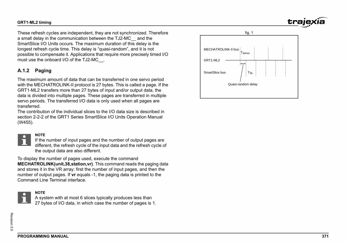
GRT1
PROG 371
Revision 5.0
fig. 1Thesea smaSmarlongepossimust
A.1.2
The mwith tGRT1data iservotransfThe csectio(W45
To disMECHand snumbComm
us
si-random delay
Tservo
TSL
-ML2 timing
RAMMING MANUAL
refresh cycles are independent, they are not synchronized. Therefore ll delay in the communication between the TJ2-MC__ and the
tSlice I/O Units occurs. The maximum duration of this delay is the st refresh cycle time. This delay is “quasi-random”, and it is not ble to compensate it. Applications that require more precisely timed I/O use the onboard I/O of the TJ2-MC__.
Paging
aximum amount of data that can be transferred in one servo period he MECHATROLINK-II protocol is 27 bytes. This is called a page. If the -ML2 transfers more than 27 bytes of input and/or output data, the s divided into multiple pages. These pages are transferred in multiple periods. The transferred I/O data is only used when all pages are erred.ontribution of the individual slices to the I/O data size is described in n 2-2-2 of the GRT1 Series SmartSlice I/O Units Operation Manual 5).
play the number of pages used, execute the command ATROLINK(unit,38,station,vr). This command reads the paging data
tores it in the VR array: first the number of input pages, and then the er of output pages. If vr equals -1, the paging data is printed to the and Line Terminal interface.
MECHATROLINK-II b
GRT1-ML2
SmartSlice bus
Qua
NOTEIf the number of input pages and the number of output pages are different, the refresh cycle of the input data and the refresh cycle of the output data are also different.
NOTEA system with at most 6 slices typically produces less than 27 bytes of I/O data, in which case the number of pages is 1.
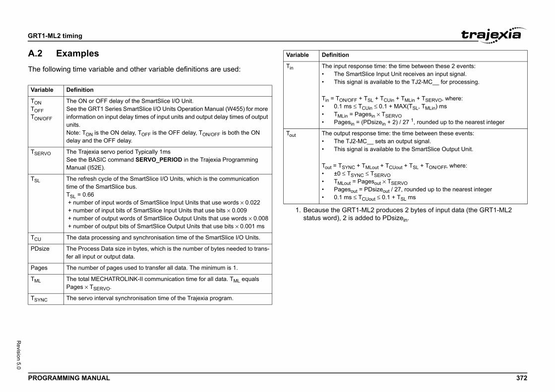
GRT1
PROG 372
Revision 5.0
A.2The f/i
Varia
TONTOFFTON/O
TSERV
TSL
TCU
PDsiz
Page
TML
TSYNC
ime: the time between these 2 events:Input Unit receives an input signal.ailable to the TJ2-MC__ for processing.
+ TCUin + TMLin + TSERVO, where: 0.1 + MAX(TSL, TMLin) ms
× TSERVOzein + 2) / 27 1, rounded up to the nearest integer
time: the time between these events:sets an output signal.ailable to the SmartSlice Output Unit.
t + TCUout + TSL + TON/OFF, where:ERVO
ut × TSERVOizeout / 27, rounded up to the nearest integer ≤ 0.1 + TSL ms
produces 2 bytes of input data (the GRT1-ML2 to PDsizein.
-ML2 timing
RAMMING MANUAL
Examplesollowing time variable and other variable definitions are used:
ble Definition
FF
The ON or OFF delay of the SmartSlice I/O Unit.See the GRT1 Series SmartSlice I/O Units Operation Manual (W455) for more information on input delay times of input units and output delay times of output units.Note: TON is the ON delay, TOFF is the OFF delay, TON/OFF is both the ON delay and the OFF delay.
O The Trajexia servo period Typically 1msSee the BASIC command SERVO_PERIOD in the Trajexia Programming Manual (I52E).
The refresh cycle of the SmartSlice I/O Units, which is the communication time of the SmartSlice bus.TSL = 0.66 + number of input words of SmartSlice Input Units that use words × 0.022 + number of input bits of SmartSlice Input Units that use bits × 0.009 + number of output words of SmartSlice Output Units that use words × 0.008 + number of output bits of SmartSlice Output Units that use bits × 0.001 ms
The data processing and synchronisation time of the SmartSlice I/O Units.
e The Process Data size in bytes, which is the number of bytes needed to trans-fer all input or output data.
s The number of pages used to transfer all data. The minimum is 1.
The total MECHATROLINK-II communication time for all data. TML equals Pages × TSERVO.
The servo interval synchronisation time of the Trajexia program.
Tin The input response t• The SmartSlice • This signal is av
Tin = TON/OFF + TSL • 0.1 ms ≤ TCUin ≤• TMLin = Pagesin• Pagesin = (PDsi
Tout The output response• The TJ2-MC__ • This signal is av
Tout = TSYNC + TMLou• ±0 ≤ TSYNC ≤ TS• TMLout = Pageso• Pagesout = PDs• 0.1 ms ≤ TCUout
1. Because the GRT1-ML2 status word), 2 is added
Variable Definition
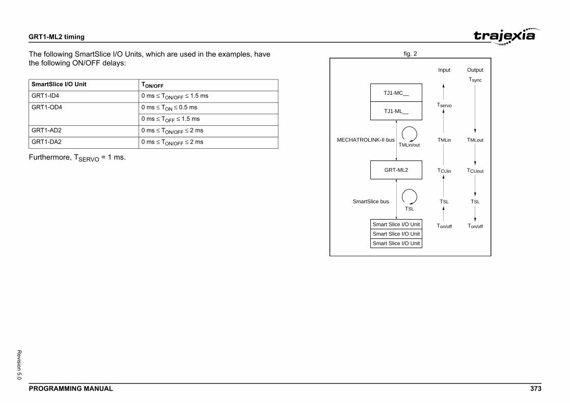
GRT1
PROG 373
Revision 5.0
fig. 2The fthe fo/i
FurthRT-ML2
t Slice I/O Unit Ton/off Ton/off
TSLTSL
TSL
TCUin TCUout
TMLin
Tservo
Input Output
TMLoutTMLin/out
Tsync
J1-ML__
J1-MC__
t Slice I/O Unit
t Slice I/O Unit
bus
s
Smar
GRT1
GRT1
GRT1
GRT1
-ML2 timing
RAMMING MANUAL
ollowing SmartSlice I/O Units, which are used in the examples, have llowing ON/OFF delays:
ermore, TSERVO = 1 ms.G
Smar
T
T
Smar
Smar
MECHATROLINK-II
SmartSlice bu
tSlice I/O Unit TON/OFF
-ID4 0 ms ≤ TON/OFF ≤ 1.5 ms
-OD4 0 ms ≤ TON ≤ 0.5 ms
0 ms ≤ TOFF ≤ 1.5 ms
-AD2 0 ms ≤ TON/OFF ≤ 2 ms
-DA2 0 ms ≤ TON/OFF ≤ 2 ms
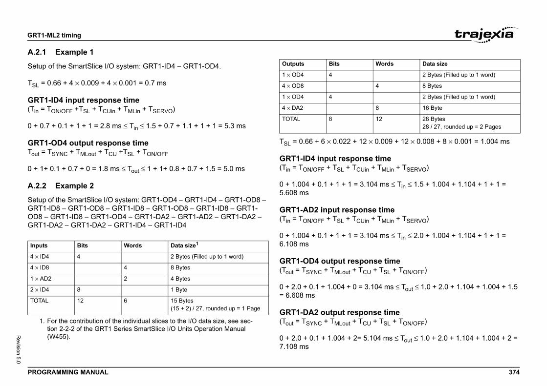
GRT1
PROG 374
Revision 5.0
A.2.1
Setup
TSL =
GRT(Tin =
0 + 0
GRTTout =
0 + 1
A.2.2
SetupGRT1OD8 GRT1/i
0.009 + 12 × 0.008 + 8 × 0.001 = 1.004 ms
time+ TMLin + TSERVO)
04 ms ≤ Tin ≤ 1.5 + 1.004 + 1.104 + 1 + 1 =
e time+ TMLin + TSERVO)
04 ms ≤ Tin ≤ 2.0 + 1.004 + 1.104 + 1 + 1 =
se time + TSL + TON/OFF)
104 ms ≤ Tout ≤ 1.0 + 2.0 + 1.104 + 1.004 + 1.5
se time + TSL + TON/OFF)
104 ms ≤ Tout ≤ 1.0 + 2.0 + 1.104 + 1.004 + 2 =
Input
1.
4 × ID
4 × ID
1 × A
2 × ID
TOTA
Words Data size
2 Bytes (Filled up to 1 word)
4 8 Bytes
2 Bytes (Filled up to 1 word)
8 16 Byte
12 28 Bytes28 / 27, rounded up = 2 Pages
-ML2 timing
RAMMING MANUAL
Example 1
of the SmartSlice I/O system: GRT1-ID4 − GRT1-OD4.
0.66 + 4 × 0.009 + 4 × 0.001 = 0.7 ms
1-ID4 input response time TON/OFF +TSL + TCUin + TMLin + TSERVO)
.7 + 0.1 + 1 + 1 = 2.8 ms ≤ Tin ≤ 1.5 + 0.7 + 1.1 + 1 + 1 = 5.3 ms
1-OD4 output response time TSYNC + TMLout + TCU +TSL + TON/OFF
+ 0.1 + 0.7 + 0 = 1.8 ms ≤ Tout ≤ 1 + 1+ 0.8 + 0.7 + 1.5 = 5.0 ms
Example 2
of the SmartSlice I/O system: GRT1-OD4 − GRT1-ID4 − GRT1-OD8 − -ID8 − GRT1-OD8 − GRT1-ID8 − GRT1-OD8 − GRT1-ID8 − GRT1-
− GRT1-ID8 − GRT1-OD4 − GRT1-DA2 − GRT1-AD2 − GRT1-DA2 − -DA2 − GRT1-DA2 − GRT1-ID4 − GRT1-ID4
/i
TSL = 0.66 + 6 × 0.022 + 12 ×
GRT1-ID4 input response(Tin = TON/OFF + TSL + TCUin
0 + 1.004 + 0.1 + 1 + 1 = 3.15.608 ms
GRT1-AD2 input respons(Tin = TON/OFF + TSL + TCUin
0 + 1.004 + 0.1 + 1 + 1 = 3.16.108 ms
GRT1-OD4 output respon(Tout = TSYNC + TMLout + TCU
0 + 2.0 + 0.1 + 1.004 + 0 = 3.= 6.608 ms
GRT1-DA2 output respon(Tout = TSYNC + TMLout + TCU
0 + 2.0 + 0.1 + 1.004 + 2= 5.7.108 ms
s Bits Words Data size1
For the contribution of the individual slices to the I/O data size, see sec-tion 2-2-2 of the GRT1 Series SmartSlice I/O Units Operation Manual (W455).
4 4 2 Bytes (Filled up to 1 word)
8 4 8 Bytes
D2 2 4 Bytes
4 8 1 Byte
L 12 6 15 Bytes(15 + 2) / 27, rounded up = 1 Page
Outputs Bits
1 × OD4 4
4 × OD8
1 × OD4 4
4 × DA2
TOTAL 8
Revision history
PROGRAMMING MANUAL 375
Revision 5.0
Revision historyA manual revision code shows as a suffix to the catalogue number on the front cover of the manual./i
Revision code Date Revised content
01 February 2010 First version
02 January 2011 TJ2-ECT__ EtherCAT master addedGRT1-ECT EtherCAT SmartSlice coupler added
03 July 2011 GX-series and FZM1-ECT added
04 February 2012 Delta robot support added
05 June 2012 TJ2-KS02 and TJ2-MC02 support added
Trajexia machine control systemTJ2-MC64, TJ2-MC02
PROGRAMMING MANUAL
Austria
Tel: +43 (0) 2236 377 800www.industrial.omron.at
Belgium
Tel: +32 (0) 2 466 24 80www.industrial.omron.be
Czech Republic
Tel: +420 234 602 602www.industrial.omron.cz
Denmark
Tel: +45 43 44 00 11www.industrial.omron.dk
Finland
Tel: +358 (0) 207 464 200www.industrial.omron.fi
France
Tel: +33 (0) 1 56 63 70 00www.industrial.omron.fr
Germany
Tel: +49 (0) 2173 6800 0www.industrial.omron.de
Hungary
Tel: +36 1 399 30 50www.industrial.omron.hu
Italy
Tel: +39 02 326 81www.industrial.omron.it
Netherlands
Tel: +31 (0) 23 568 11 00www.industrial.omron.nl
Norway
Tel: +47 (0) 22 65 75 00www.industrial.omron.no
Poland
Tel: +48 22 645 78 60www.industrial.omron.pl
Portugal
Tel: +351 21 942 94 00www.industrial.omron.pt
Russia
Tel: +7 495 648 94 50www.industrial.omron.ru
South-Africa
Tel: +27 (0)11 579 2600www.industrial.omron.co.za
Spain
Tel: +34 913 777 900www.industrial.omron.es
Sweden
Tel: +46 (0) 8 632 35 00www.industrial.omron.se
Switzerland
Tel: +41 (0) 41 748 13 13www.industrial.omron.ch
Turkey
Tel: +90 212 467 30 00www.industrial.omron.com.tr
United Kingdom
Tel: +44 (0) 870 752 08 61www.industrial.omron.co.uk
OMRON EUROPE B.V. Wegalaan 67-69, NL-2132 JD, Hoofddorp, The Netherlands. Tel: +31 (0) 23 568 13 00 Fax: +31 (0) 23 568 13 88 www.industrial.omron.eu
Authorised Distributor:
Note:Although we do strive for perfection, Omron Europe BV and/or its subsidiary and affiliated companies do not warrant or make any representations regarding the correctness or completeness of information described in this catalogue. Product information in this catalogue is provided ‚as is‘ without warranty of any kind, either express or implied, including, but not limited to, the implied warranties of merchantability, fitness for a particular purpose, or non-infringement. In a jurisdiction where the exclusion of implied warranties is not valid, the exclusion shall be deemed to be replaced by such valid exclusion, which most closely matches the intent and purpose of the original exclusion. Omron Europe BV and/or its subsidiary and affiliated companies reserve the right to make any changes to the products, their specifications, data at its sole discretion at any time without prior notice. The material contained in this catalogue may be out of date and Omron Europe BV and/or its subsidiary and affiliated companies make no commitment to update such material.
Cat. No. I58E-EN-05
Trajexia machine control system PROGRAMMING MANUAL
Cat. No.I58E-EN-05
Cat. No.I58E-EN-05