Embed Size (px)
Citation preview
I
TD6-1i-5 - BlnK5
DMSION PO/=
- -- -
TRAINING Spray Booths z4&
1. GENERAL DESCRIPTION: Spray booths are fire and health protection enclosures scientifically designed to provide a positive movement of air through the spray area. This causes the solvent fumes to be carried to the atmosphere and most solid particles to be eliminated in the filter system. Most spray booth designs will incorporate a method of filter- ing or washing the solid particles from the air before discharge. When properly designed and installed, a spray booth can provide the following advantages:
1.
2.
3.
4.
6.
Safety-through the removal of volatile solvent fumes from the spray area Lower insurance rates-some states provide a tax advantage to firms using spray booths. This is generally based on the reduction of air and water pollution and noise abatement. Finish quality-improved when a majority of the overspray is removed from the spray area, pre- venting unnecessary contamination of other work in the area Working environment-of the spray operators and others in the immediate area is improved. Community relations-proper filtration of ex- hausted air will minimize air pollution, and dam- age to neighboring property.*
Spray booths can be categorized by their types and their methods of filtration as follows:
SPRAY BOOTHS
I I I I
DhY TYPE
I W A ~ E R SPE~IAL
TYPE I WASH TYPE
I I
I 1 I SOLVENT STANDARD NO
PUMP ENVIROTECH PUMP TYPE TYPE I
F ~ I T I
POWDER
F I L ~ BAFFLE
I I 1 WOVEN
PAD PLEATED POLY ESTER
When selecting a spray booth, it is advisable to check the safety, fire, insurance, underwriters and building
*Binks Spray Booths conform with OSHA and EPA regula- tions and are designed expressly to separate particulate matter from the air being discharged to the atmosphere. However, volatile organic compounds in the form of vapors may not be so separated and attention may need to be given to coating reformulation or optional addition- al "separator" equipment.
codes which effect your area to determine the type of spray booths that are acceptable:
Dry type spray booths are those that use a mechanical means to distribute the air movement evenly and pro- vide proper filtration when required. No water is re- quired for filtration. However, in some areas, water may be required h the area for fire protection or clean-up. 1. Baffle booths-are the most fundamental type.
Baffle plates are used to distribute the flow of air through the spray area and prevent some of the solid particles from being exhausted into the air. They generally are seen in applications where small spraying operations take place intennittent- ly and the discharged air does not have to be free of paint particles.
a. Lower in cost. b. Baffles are designed to provide uniform air
flow through the booth and eliminate some of the slow drymg particles.
A. DRY TYPE SPRAY BOOTHS:
2. Advantages of baffle booths:
c. Light in weight if floor loading is a problem. d. Suitable for use with most types of material. e. Suitable for limited production where generally
not more than two gallons of paint are sprayed per day, with standard cataloged booths.
f. Low cost of installation. g. No filter replacement required.
a Limited filtration of minute paint particles. b. Baffles must be stripped when excess paint
c. Designed to handle only limited production. d. Can not handle all materials-operates best
with slow drying materials. (See Page 14 for illustration.)
3. Limitations of baffle booths:
accumulates.
8. FILTER TYPE SPRAY BOOTHS: Filter booths provide a mechanical means of filtering the air by passing it through a form of filter media. This filter also serves as a means of distributing the air flow evenly through the spray booth. Obviously, as the filter removes the solids, it will gradually build up a restriction to the flow of air, requiring change of the filter media. An air pressure differential gauge (manometer) should be installed on the side of the booth with the pilot tube placed on the intake side and the other tube on the exhaust side of the filter bank to indicate a pressure differential (drop) across the filter bank. When a new filter bank has been installed, a reading should be taken and noted. The filters will require replacement when a .25 inch increase is indicated on the manometer. In some
/
\
states requirements dictate that a pressure differen- tial switch be installed to cut off the air to the spray guns leading into the spray booth area, whenever the air velocity drops below a certain point. The pressure drop is generally considered and measured in inches of rinse in a column of water.
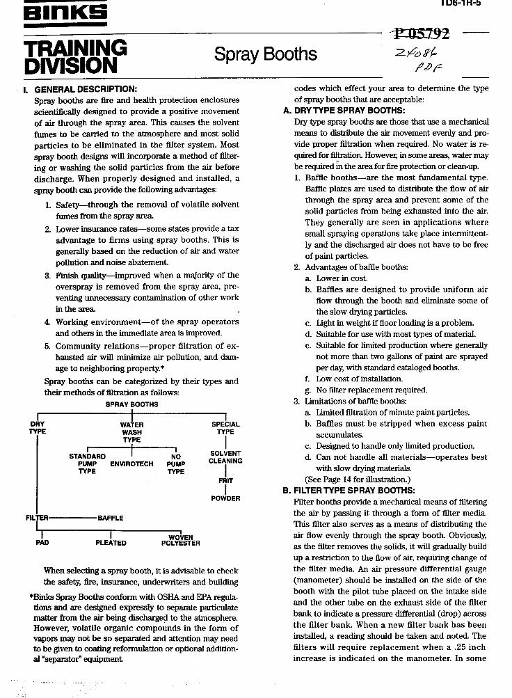
1. Pad type: Pad filters are made of a fire-retardant treated pa- per and formed into a "honeycomb" configuration. The filtering action is accomplished by the rapid "back and forth" movement of the air as it passes through the filter media. Centrifugal force throws the solids against the treated paper where it sticks. When spraying in one spot the exhaust air moves the paint particles over until most of the filter area becomes filled. As the filter loads up with paint particles and the air movement through the spray booth diminishes and a one half inch ( . 5 0 total) rise in a column of water is indicated, the filters then require replacement.
There are two paper filters placed in each filter frame in back of the spray booth. The number of frames in any spray booth will be determined by size of the filter bank in back of the spray booth. The two most common sizes of filter media avail- able are: 1x20~20 or 1x20~25 and held QI place by a press fitted wire grid. Additional sizes are avail- able on request.
Upon replacement of the filter media, the first dirty filter, that which traps most of the paint is removed and disposed of in a prescribed manner. The second filter is also removed but not disposed of. A new fil- ter is then placed in the filter frame and the old sec- ond filter is now replaced over the new filter. Using this procedure minimizes filter replacement cost. ------.
GRID /
A double layer of one inch thick pads is used. Only one layer need be replaced at a time as bulk of paint particles are caught in the first inch of filter thickness.
F 2. Pleated
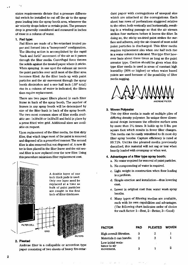
Andreae filter is a collapsible or accordion type paper consisting of two sheets of heavy fire-retar-
dant paper with corrugations of unequal size which are attached at the corrugations. Each sheet has rows of perforations staggered relative to the other, both vertically and horizontally, result- ing in a winding passage so that the air stream strikes four surfaces before it leaves the filter. In doing so, the sticky un-dried paint strikes the sur- face and adheres, only the ah cleaned of most solid paint particles is discharged. This filter media requires replacement also when one half inch rise in a water column is indicated. This type filter how- ever lasts about three times as long as the paint arrestor type. Caution should be given when this type filter media is used in areas of constant high humidity (90% or higher) or when water based paints are used because of the possibility of filter media sagging.
ANDREAE FILTER
3. Woven Polyester This dry filter media is made of multiple plies of differing density polyester. Its unique three dimen- sional design increases the effective surface area by more than 2% times. It holds up to 6 lbs. per square foot which results in fewer filter changes. This media can be easily retrofitted to fit most dry filter spray booths. Capture efficiency is rated at 99.71%. Unlike the pleated media previously described, this material will not sag or tear when heavily loaded with overspray or when wet.
4. Advantages of a filter type spray booth: a No water required for removal of paint particles.
b. No compounding of water is required. c. Light weight in construction when floor loading
d. Simple erection and installation-thus lowering
e. Lower in original cost than water wash spray booths.
f. Many types of filtering medias are available, each with its own capabilities and advantages. (The following chart indicates order of choice for each factor: 1-Best, 2-Better, M o o d )
is a problem.
cost.
FACTOR PAD PLEATED WOVEN
High overall filtration. 3 2 1 Materials it can handle. 2 3 1
Low initial resis- tance to air movement. 3 1 2
2
. I
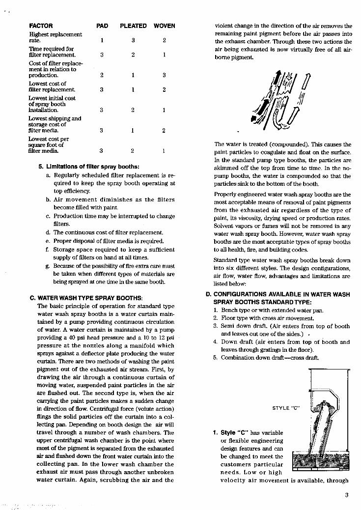
FACTOR Highest replacement rate. Time required for filter replacement. Cost of filter replace- ment in relation to production. Lowest cost of filter replacement. Lowest initial cost of spray booth installation. Lowest shipping and storage cost of filter media Lowest cost per square foot of filter media.
PAD
1
3
2
3
3
3
3
PLEATED WOVEN
3 2
2 1
1 3
1 2
2 1
1 2
2 1
5. Limitations of filter spray booths: a. Regularly scheduled filter replacement is re-
quired to keep the spray booth operating at top efficiency.
b. Air movement diminishes as the filters become filled with paint.
c. Production time may be interrupted to change filters.
d. The continuous cost of filter replacement. e. Proper disposal of filter media is required. f. Storage space required to keep a sufficient
supply of filters on hand at all times. g. Because of the possibility of fire extra care must
be taken when different types of materials are being sprayed at one time in the same booth.
C. WATER WASH TYPE SPRAY BOOTHS: The basic principle of operation for standard type water wash spray booths is a water curtain main- tained by a pump providing continuous circulation of water. A water curtain is maintained by a pump providing a 40 psi head pressure and a 10 to 12 psi pressure at the nozzles along a manifold which sprays against a deflector plate producing the water curtain. There are two methods of washing the paint pigment out of the exhausted air stream. First, by drawing the air through a continuous curtain of moving water, suspended paint particles in the air are flushed out. The second type is, when the air canying the paint particles makes a sudden change in direction of flow. Centrifugal force (volute action) flings the solid particles off the curtain into a col- lecting pan. Depending on booth design the air wil l travel through a number of wash chambers. The upper centrifugal wash chamber is the point where most of the pigment is separated from the exhausted air and flushed down the front water curtain into the collecting pan. In the lower wash chamber the exhaust air must pass through another unbroken water curtain. Again, scrubbing the air and the
violent change in the direction of the air removes the remaining paint pigment before the air passes into the exhaust chamber. Through these two actions the air being exhausted is now virtually free of all air- borne pigment.
The water is treated (compounded). This causes the paint particles to coagulate and float on the surface. In the standard pump type booths, the particles are skimmed off the top from time to time. In the no- pump booths, the water is compounded so that the particles sink to the bottom of the booth.
Properly engineered water wash spray booths are the most acceptable means of removal of paint pigments from the exhausted air regardless of the type of paint, its viscosity, drying speed or production rates. Solvent vapors or fumes will not be removed in any water wash spray booth. However, water wash spray booths are the most acceptable types of spray booths to all health, fie, and building codes.
Standard type water wash spray booths break down into six different styles. The design configurations, air flow, water flow, advantages and limitations are listed below:
D. CONFIGURATIONS AVAILABLE IN WATER WASH SPRAY BOOTHS STANDARD TYPE: 1. Bench type or with extended water pan. 2. Floor type with cross air movement. 3. Semi down draft. (Air enters from top of booth
and leaves out one of the sides.) 4. Down draft (air enters from top of booth and
leaves through gratings in the floor). 5. Combination down draft-cross draft.
STY 1
1. Style “C” has variable or flexible engineering design features and can be changed to meet the customers particular needs. Low or high
.E
velocity a i r movement is available, through
3

booth area. The air receives four washes as it passes through the spray booth water curtains. It is the most efficient standard type water wash spray booth designed because it also incorporates a bafflebacked curtain and is moderate in cost. It has a water flow of 24 gallons per foot of booth with a 60 gallon return. The eliminator section is variable to meet design needs. The air velocity through the eliminator is from 500 CFM to 2,000 CFM per foot of eliminator.
2. Style “E” operates on the same principle as the style “C”. This spray booth is the standard cata- loged spray booth with a tixed design and single back curtain. This spray booth is composed of standard size panels therefore it does not require any custom engineering. It features an upper and lower wash chamber, large capacity collecting pan,,slotted water intake pipe to insure sediment free water, circulating water system which forms a, constantly flushed circuit, removable manifold for ease of maintenance, hinged water curtain to allow easy access to the rear of the collecting pan, recessed drain which insures complete removal of water from the pan, access door located just below the fan for easy maintenance. The air receives four washes, has a water flow of 24 gal- lons per foot of booth with a 60 gallon return, an adjustable air velocity of 1050 CFM to 1250 CFM per foot of width of the wash chamber. This unit is the most economical unit to purchase and oper- ate as far as efficiency is concemed.
3. NO-PUMP SPRAY BOOTH: The no-pump booth is a high resistance booth. The principles of operation are as follows: A high static pressure fan, which is located in the spray booth exhaust duct, pulls the air under an entrain- ment plate at a very high velocity. As the high velocity air current is pulled under the plate, the air movement forces the water surface into a stream which also flows under the plate. This water stream increases in velocity until it is actu- ally lifted into a rotating cascade or waterfall just
4
behind the entrainment plate. The air current must pass through this cylindrically shaped turbu- lent water column. At that time the solid paint particles in the air stream become trapped within the water column by the centrifugal force which is created by the rotating column of air and water. Washing takes place as the air escapes through the water, leaving the paint particles in solution behind. The rising &-water column strikes the eliminator plates within the spray booth exhaust unit which causes this high velocity mixture to rapidly change direction several times. As a result, the moisture precipitates out and falls back into the tank. Clean air is then exhausted through the fan to the atmosphere.
NOPUMP SPRAY BOOTH CROSS SECTION
PLATE DISTRIBUTION, fAccEss ‘‘OR
i n ENTRAINMENT, PLATE BAFFLES
NOPUMP SPRAY BOOTH , I
ENTRAINMENT PLATE PROFILE
The water in this booth is compounded so that the paint particles sink to the bottom. The paint solids come coated with an anti-coagulant which has been added to the water, and together with the water are precipitated into the tank. Drain open- ings in the rear of the spray booth allow the paint and water mixture to retum to the front of the tank through a trough.
Heavier paint solids settle to the bottom while lighter particles recirculate until they are broken down and the pigment released. If larger amounts of moisture accumulate on the top baf- fles, this indicates too much foaming and requires the addition of a heavy weight oil to be added to the water.
The critical factor determining the proper opera- tion of a no-pump spray booth is the air velocity. Air velocity is controlled by the water level. As the water level lowers in the tank, the distance between the water surface and entrainment plate increases resulting in a change in the air velocity within the spray booth. This velocity change or pressure differential is sensed by a probe which
.- .
activates an automatic water level control valve which maintains the proper level of water in the tank and proper air velocity to operate the spray booth efficiently.
When selecting a no-pump spray booth one must have adequate air make-up available. If a vacuum occurs in the building, the water level control valve wi l l not sense the water level correctly.
If the fan is to be mounted on the roof, the total static resistance must be accounted for; from the plenum chamber (or adapter ring) into the stack, plus the normal loss through the length of the stack being used.
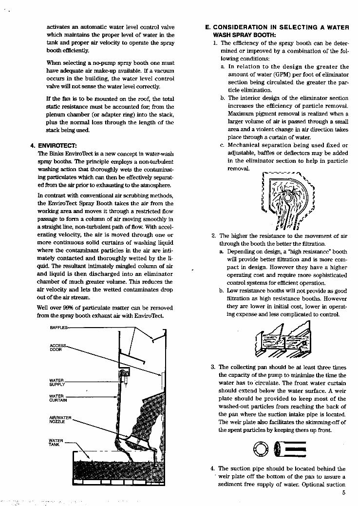
4. ENVIROTECT: The Binks EnviroTect is a new concept in water-wash spray booths. The principle employs a non-turbulent washing action that thoroughly wets the contaminat- ing particulates which can then be effectively sepaxat- ed from the air prior to exhausting to the atmosphere.
In contrast with conventional air scrubbing methods, the EnviroTect Spray Booth takes the air from the working area and moves it through a restricted flow passage to form a column of air moving smoothly in a straight line, non-turbulent path of flow. With accel- erating velocity, the air is moved through one or more continuous solid curtains of washing liquid where the contaminant particles in the air are inti- mately contacted and thoroughly wetted by the li- quid. The resultant intimately mingled column of air and liquid is then discharged into an eliminator chamber of much greater volume. This reduces the air velocity and lets the wetted contaminates drop out of the air stream.
Well over 99% of particulate matter can be removed from the spray booth exhaust air with EnviroTect.
BAFFLES
E. CONSIDERATION IN SELECTING A WATER WASH SPRAY BOOTH: 1. The efficiency of the spray booth can be deter-
mined or improved by a combination of the fol- lowing conditions: a. In relation to the design the greater the
amount of water (GPM) per foot of eliminator section being circulated the greater the par- ticle elimination.
b. The interior design of the eliminator section increases the efficiency of particle removal. Maximum pigment removal is realized when a larger volume of air is passed through a small area and a violent change in air direction takes place through a curtain of water.
c. Mechanical separation being used fixed or adjustable, baffles or deflectors may be added in the eliminator section to help in particle removal. r ------= =
2. The higher the resistance to the movement of air through the booth the better the filtration. a. Depending on design, a “high resismce” booth
will provide better filtration and is more com- pact in design. However they have a higher operating cost and require more sophisticated control systems for efficient operation.
b. Low resistance booths will not provide as good atration as high resistance booths. However they are lower in initial cost, lower in operat- ing expense and less complicated to control.
3. The collecting pan should be at least three times the capacity of the pump to minimize the time the water has to circulate. The front water curtain should extend below the water surface. A weir plate should be provided to keep most of the washed-out particles from reaching the back of the pan where the suction intake pipe is located. The weir plate also facilitates the skimming-off of the spent particles by keeping them up front.
4. The suction pipe should be located behind the ’ weir plate off the bottom of the pan to assure a
sediment free supply of water. Optional suction 5
, . , . . , .. . . . .

. t
screens can be provided when required. The water level should be maintained by manual or an automatic float valve system.
5. The booths should have a water circulating sys- tem with no dead-ends to trap sediment. The water flow rate should be easily acijustable to suit the water circulation requirements.
6. The maintenance requirement of the booth should be considered such as:
a. Removable manifold to simplify the occasional cleaning and inspection of the upper wash chamber.
b. Easy access should be available to the back of the collecting pan for ease of skimming the entire pan and servicing the pump suction pipe.
c. The position of the drain should be recessed to insure complete removal of the water from the collecting pan.
d. An access door should be provided below the fan to allow easy inspection, repair or replace- ment of parts.
7. The type of compound required should be consid- ered. This is determined by the style booth, type of material sprayed and the material supplier or compound makers recommendations.
8. One should therefore consider the above listed features and find an efficient booth to meet his needs, local codes, requirements and budget.
F. ADVANTAGES OF A WATER WASH SPRAY BOOTH:
1. Accepted by most local codes as the best type
2. Most types of makrials can be sprayed into water
3. Any production rate can be met.
4. No filter replacement, filter cost, or wasted space
spray booth available.
wash spray booths.
for filter storage.
G. LIMITATIONS:
1. The water must be compounded in such a way that the spent paint particles will either float or
6
2.
3.
4.
5.
6.
sink depending on the type booth or material being used.
The standard type water wash spray booths require constant circulation of water.
Floor loading might be a problem due to the weight of the water.
Higher initial cost.
Materials that cannot be made to float should not be used in standard water-wash spray booths. Materials which create excessive foaming or will not settle to the bottom cannot be sprayed in a no- pump booth.
The possibility of water pollution should be con- sidered.
H. DOWN DRAFT AND DOWN DRAFT SPRACURE BOOTHS: A downdraft spray booth is used to paint all types of motor vehicles. It is available in two models-Solid Back and Drivel”.
The downdraft principle is one in which ambient or heated air is introduced and forced through filters at the top of the booth. The air flows over the top of the vehicle, around the sides, and is pdled downwards through filters beneath the floor grate. This downward air flow helps to minimize rejects by pushing over- spray to the floor instead of along the vehicle being sprayed. (In contrast, the air flow in a conventional booth goes from one end of the booth to the other.)
The SprZCure Booth combines the same downdraft principle with the cost effective curing method of infra-red heaters. The infra-red heaters help save money because heat is only generated when the rays strike a solid surface. The SpSCure principIe can also be used in conventional cross draft spray booths.
II. TYPES OF SPRAY BOOTHS: There are many types of spray booths for just about any type of spray application possible. All these different types are designed to meet the particular needs of the product. The filtration needs of the spray booth can be designed into any type of spray booth required. The type of filtration of the exhaust will be determined by the local codes pertaining to the operation of a spray booth in your area Note: for those who are concerned about air pollu- tion a booth with better filtration can always be selected.
1. Bench type or touch up spray booths: a A small spraying area elevated above the floor so
that the spray operator does not have to stoop. b. Parts which are to be sprayed are either carried
into the spray booth manually or on a conveyor. c. Bench booths are available with any of the fol-
lowing means of filtration or distribution of the air movement through the booth. (1) BafXePlates. (2) Distribution Plates.
. .-

(3) Perforated baffles (for vitreous enamels, latex and adhesives).
(4) Padflters (5) Pleatedfilters. (6) (7) V m l or grease stop filters. (8) Metal cleanable for grinding operations. (9) Flock screen with distributing plates.
Dkhibuting plates with filters. (U-V)
2. Floor type or walk-in: a Can be used for spraying small parts on a turn-
table or large hard to move items. b. Items to be sprayed may be carried in by the
operator or on a conveyor. c. The air movement is always directed over the
spray operator from behind carrying away all contarmnate S.
d. Floor type spray booths can have the same means of air distribution and filtration as bench type booths (listed above). The direction of the air movement through the spray booth can be: (1) Cross draft. (2) Semidowndraft. (3) Downdraft.
3. Special purpose spray booths: a Dry type for ceramic materials. b. Varsol type for solvent spraying and cleaning
c. Spray booths for spraying materials that cor- rode ferrous metals, are usually constructed of aluminum or stainless steel.
d. Down draft water wash spray booths designed to take in air from the ceiling and then be removed through gratings in the floor. This type of installation is the cleanest type and it is widely used in the automotive industry.
of parts.
e. Barrel rotating spray booth. f. h c k spray booth. g. Automotive spray booth for the refinishing of
automobiles. (1) Downdraft
(2) DryF'ilter (a) Downdraft Sp6Cure
(4 pad @) Pleated (c) Woven
h. Exhaust chambers, baffle or filter type where a fire proof room is available for spraying. Exhaust chambers can convert the room into a spray m a These chambers are the back sec- tion of standard type spray booths.
i. Flock type for spraying powdered materials utilizing a wire screen and distribution plates.
j. Grinding booths which contain expanded metal cleanable filters.
k. Down draft dry bench booths for vitreous enamels or grinding operations.
1. Canopy booths using baffles or filters. (Works similar to a steam table.)
111. CONSIDERATIONS WHEN SELECTING A SPRAY BOOTH: The selection of the proper spray booth requires consid- erable thought. The initial investment in a spray booth can be returned many times over if the correct one has been selected for your needs.
Some of the most important considerations are:
A. SPACE AVAILABLE FOR THE SPRAY BOOTH AND ITS LOCATION: 1. Consideration should be given as to where the
spray booth should be located and that the area provided can accommodate the complete spray booth. Special attention should be given to the overhead areas; air ducts, piping, structural mem- bers, where, how far, and in what direction the exhaust stack must go to take the exhaust air from the spray booth. Making certain that all access doors can be open is another essential factor. The overall outside dimensions of most dry type spray booths can be calculated by adding two inches to each side and two inches to the back if only the inside dimensions are given. These two inches are normally required for the outside flange. A mini- mum clear space in front of the booth equal to twice the height of the front end of the booth must be provided for. This will give the best possible operation of the spray booth.
2. The amount of air movement through the booth, the type of filtration needed, type of booth required.
3. The flow of products to and from the spray area should be as direct as possible. One consideration is the movement of the product directly through the spray booth, working depth walls.
4. It is advantageous to have a large drain available in the spray booth floor. This will permit the washing down of the spray area, prevent air con- tamination of the product, and facilitate clean up. However, one should check with local codes to see if this is permissible.
5. It is desirable to build the spray booth on a cement curb. This will minimize the accumulation of water under the booth flange and will also pro- vide a level surface for the erection of the spray booth in addition to extending its useful life. This is especially important for those who wish to wash down the floor of the booth frequently.
6. The electrical power and water requirements for the spray booth operation such as: location, avail- ability of the proper voltage, current, cycles, phase and type of electrical equipment that is going to be required for the spray booth installation.
7. The altitude must be considered in the selection of
7
the exhaust fan and motor because fans must operate at higher R.P.M.’s and in most cases alti- tude in excess of 3,600 feet above sea level they also require special motors.
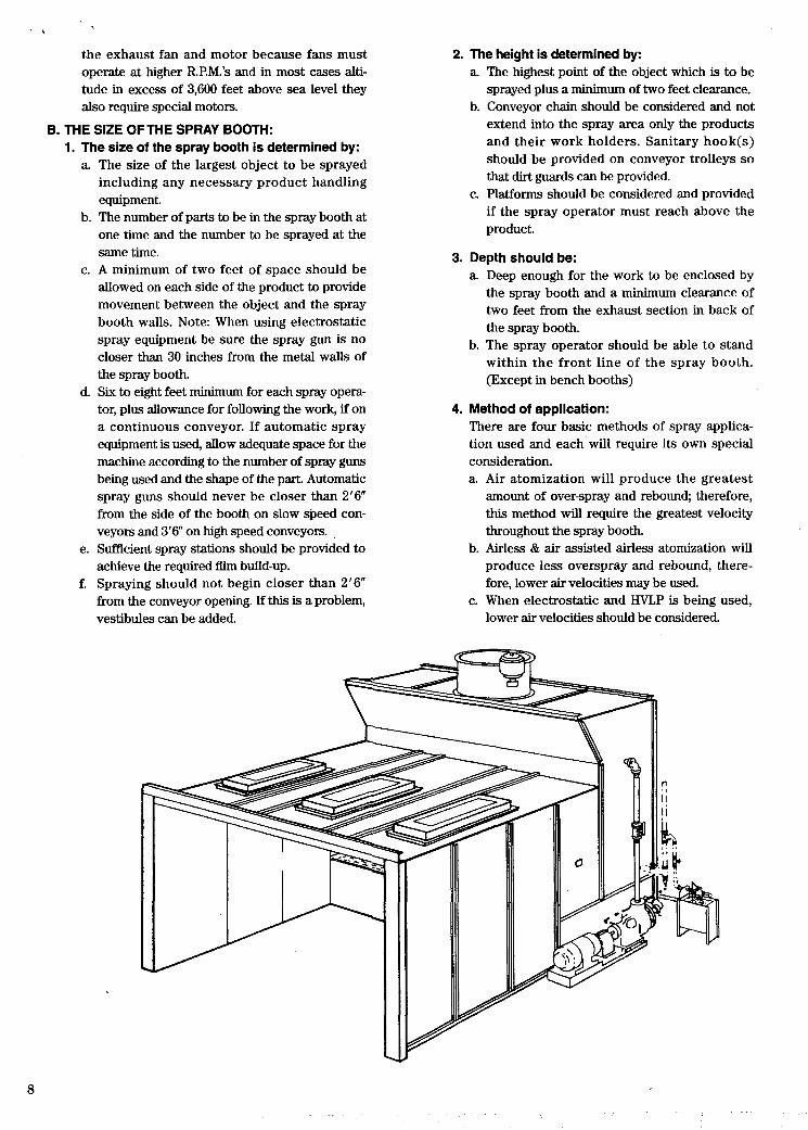
B. THE SIZE OFTHE SPRAY BOOTH: 1. The size of the spray booth is determined by:
a. The size of the largest object to be sprayed including any necessary product handling equipment.
b. The number of parts to be in the spray booth at one time and the number to be sprayed at the same time.
c. A minimum of two feet of space should be allowed on each side of the product to provide movement between the object and the spray booth walls. Note: When using electrostatic spray equipment be sure the spray gun is no closer than 30 inches from the metal walls of the spray booth.
d. Six to eight feet minimum for each spray opera- tor, plus allowance for following the work, if on a continuous conveyor. If automatic spray equipment is used, allow adequate space for the machine according to the number of spray guns being used and the shape of the part. Automatic spray guns should never be closer than 2 ’ 6 from the side of the booth on slow speed con- veyors and 3 ’ 6 on high speed conveyors.
e. Sufficient spray stations should be provided to achieve the required film build-up.
f. Spraying should not begin closer than 2’6” from the conveyor opening. If this is a problem, vestibules can be added.
2. The height is determined by: a. The highest point of the object which is to be
sprayed plus a minimum of two feet clearance. b. Conveyor chain should be considered and not
extend into the spray area only the products and their work holders. Sanitary hook(s) should be provided on conveyor trolleys so that dirt guards can be provided.
c. Platforms should be considered and provided if the spray operator must reach above the product.
3. Depth should be: a. Deep enough for the work to be enclosed by
the spray booth and a minimum clearance of two feet from the exhaust section in back of the spray booth.
b. The spray operator should be able to stand within the front line of the spray booth. (Except in bench booths)
4. Method of application: There are four basic methods of spray applica- tion used and each will require its own special consideration. a. Air atomization will produce the greatest
amount of over-spray and rebound; therefore, this method will require the greatest velocity throughout the spray booth.
b. Airless & air assisted airless atomization will produce less overspray and rebound, there- fore, lower air velocities may be used.
c. When electrostatic and HVLP is being used, lower air velocities should be considered.

d. True electrostatic (bell or disc) atomization will produce the least amount of over-spray and too high an air velocity will pull the paint particles past the product.
D. THE EXHAUST FAN: The exhaust fan is the heart of any spray booth. A fan wheel acts very much like a shovel. Every time it revolves it discharges the same quantity of air. In a system the fan will discharge the same volume of air each revolution regardless of the fan speed and air C. AIR VELOCITY:
. . .
The air velocity must be high enough to cany all solvent vapors and overspray away from the paint- ing area Low air velocities can cause dangerous conditions and increase maintenance cost. The average velocity for most materials and appli- cation methods is 100 F.P.M. (feet per minute) Note: 175 to 200 F.P.M. can be obtained when the application involves ceramic materials or auto- matic reciprocating machines. Electrostatic spraying requires somewhat lower air velocities depending on whether air or airless electrostatic attraction is being used or true elec- trostatic atomization, (mini" 60 F.P.M.). The volume of air and velocity for a spray booth exhaust system can be calculated by using the fol- lowing formula: Width x Height (plus the area of one conveyor opening) x Velocity desired will equal C.F.M. of air required through the spray booth. Depth of the spray booth is not figured in the calculation. Other considerations are: a Velocities through booths generally range from
100 F.P.M. to 200 F.P.M. and vary with the type of operation taking place within the booth, for example: (1) Flock spray booths (75 F.P.M.) (2) The electrostatic spraying (SO F.P.M.) (3) Electrostatic attraction (60-100 F.P.M.) (4) Auto and truck booths limited production
(100 F.P.M.) (5) Hand spray (100 to 150 F.P.M.) (6) Auto spray booth for production with air
atomizing spray guns (100-150 F.P.M.) (7) Auto spray booths for production with
electrostatic (60-100 F.P.M.) (8) Varsol(150 F.P.M.) (9) Vitreous enamels (165 to 175 ERM.) (10) Grinding booth (150 F.P.M.) (11) Down draft booth (35 to 100 F.P.M.)
b. In filter booths because of the limited air veloci- ty through the filters, the filter area may have to be increased to maintain adequate air velocity through booth.
c. The calculated c.f.m. must also include losses accrued in the system due to static pressure as the air flows through the exhaust stack and elbows. The computations made must then be compared to a standard exhaust fan table. Exhaust fan can be sized by manufacturer if customer provides basic data Height of roof, location of booth, length of stack, number of elbows, and height of stack above roof.
. .
~ - density. Note: disregarding small effects of com- pression at high pressure. The nature of a fan is such that they will operate at the same efficiency at all points in a system regardless of where it is placed.
The performance of a fan is based on three basic laws. The fan manufacturer can provide fan perfor- mance tables and curves which graphically shows all possible combinations of C.F.M. and static pressure possible for any given system. There are however, a great many other considerations which enter into an individual fan selection for a system. Therefore before one is able to engineer a system he should always check with the fan manufacturer to find out what type of exhaust fan should be used, its size, and efficiency required for your particular application. Many manufacturers will engineer the system for you if you provide them with the necessary information required to make their calculations.
The noise level in most industrial applications by present methods of measuremenf. are generally acceptable up to 85 decibels depending on condi- tions. Unfortunately at present there are not set stan- dards for rating the noise level of fans in such a way that it will have any real value. Fan noise may be attributed to many factors. The most important are the volume of air, capacity, horsepower, ambient con- ditions, general construction of the fan and the pas- sages the air must follow. However there is a reasonably accurate measuring system available. It has been found that in the medium horsepower range the noise level is in direct proportion to the fan tip speed. The tip speed table below and the previous fan table can be useful in approximating the noise level ratings. This table is only intended to be used as a guide and as an absolute value. Common sense and experience at present are the real factors to con- sider in the design where noise levels may be critical.
9

tlp speed chart
Fan Tip Speed (feet per minute)
6000- 8000 8000-10000
10000-12000 12000-14000 14000 - 16000 16000 - 18000 18000 - 20000
PRESSURE VAC,UUM
Decibels (approximate)
60- 65 65- 72 72- 79 79- 85 85 - 91 91 - 97 97 - 103
12- 14’ 16’ 18’ 21‘
so00
VJOO
UPM
una
1800
I110
1000 Lo
wo a
If noise level is a problem then one should select a larger exhaust fan if possible. A larger exhaust fan will permit lowering of the fans R.P.M. and this will lower the noise level and still provide sufficient air movement. The customer should provide decibel Eading required then Binks will size the fan accord- ingly. Blowers can be furnished if proper noise level cannot be obtained by the use of the standard vaneaxial fan.
STATIC PRESSURE: Air moving through a duct system under the action of a fan has two pressure components, static pressure and velocity pressure. Static pressure acts in all directions and is of uniform magnitude in any given chamber of the duct system. Velocity pressure acts in the direction of the flow and can be detected by its effect on a streamer placed in the duct chamber. Total pressure is the sum of static pressure and velocity pressure.
Because normal operating pressures in spray booth duct systems are low their magnitude is measured by the vertical distance they cause water to rise, hence the term “inches of water column pressure”. An instrument for indicating such pressures i s the
Fig. 1. In its sim- plest form the manometer is a U-tube about half filled with liquid. With both ends of the tube open, the liquid is at the same height in each leg.
Fig. 2. When posi- tive pressure is applied to one leg, the liquid is forced down in that leg and up in the other. The differ- ence in height, “h,” which is the sum of the readings above and below zero, indicates the pressure.
Fig. 3. When a vacuum is applied to one leg, the liq- uid rises in that leg and falls in the other. The differ- ence in height, “h,” which is the sum of the read- ings above and below zero, indi- cates the amount of vacuum.
Courtesy of Dwyer Instruments, Inc.
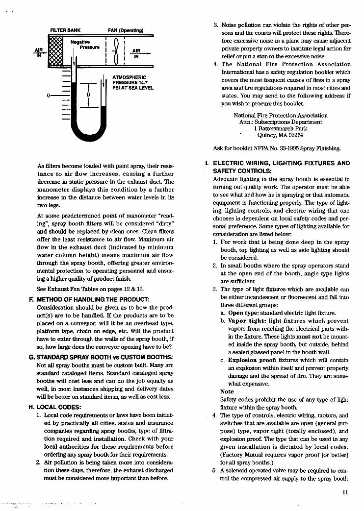
The manometer can be used to indicate the condition of filters in the exhaust system of a paint spray booth. When the exhaust fan is not operating, static air pressure is the same throughout the system. The manometer indicates this condition by displaying “zero” height of water column, as in Fig. 4.
FILTER BANK FAN ( Operatins
- - ATMOSPHERIC PRESSURE, 14.7 PSI AT SEA LEVEL - -I I 111
0-
Fig. 4. Zero inches of water column
With the exhaust fan operating, as in Fig. 5, a nega- tive static pressure is developed in the space between fan and filters because of the resistance the fllters impose on the free flow of air through the exhaust duct. This negative static pressure is indicat- ed by the rise in height of water level in one leg of the manometer and the corresponding drop in the other leg. The distance “D“ between water levels is called the “water column height” and usually is expressed in inches.
P flLlER BANK FAN (Operating)
0
I ATMOSPHERIC PRESSURE 14.7 PSI AT SEA LEVEL
=I I
F.
As filters become loaded with paint spray, their resis- tance to air flow increases, causing a further decrease in static pressure in the exhaust duct. The manometer displays this condition by a further increase in the distance between water levels in its two legs.
At some predetermined point of manometer “read- ing”, spray booth filters will be considered “dirty” and should be replaced by clean ones. Clean filters offer the least resistance to air flow. Maximum air flow in the exhaust duct (indicated by minimum water column height) means maximum air flow through the spray booth, offering greater environ- mental protection to operating personnel and ensur- ing a higher quality of product finish.
See Exhaust Fan Tables on pages 12 & 13.
METHOD OF HANDLING THE PRODUCT: Consideration should be given as to how the prod- uct(s) are to be handled. If the products are to be placed on a conveyor, will it be an overhead type, platform type, chain on edge, etc. Will the product have to enter through the walls of the spray booth, if so, how large does the conveyor opening have to be?
G. STANDARD SPRAY BOOTH vs CUSTOM BOOTHS: Not all spray booths must be custom built. Many are standard cataloged items. Standard cataloged spray booths will cost less and can do the job equally as well, in most instances shipping and delivery dates will be better on standard items, as well as cost less.
H. LOCAL CODES: Local code requirements or laws have been initiat- ed by practically all cities, states and insurance companies regarding spray booths, type of filtra- tion required and installation. Check with your local authorities for these requirements before ordering any spray booth for their requirements. Air pollution is being taken more into considera- tion these days, therefore, the exhaust discharged must be considered more important than before.
1.
Noise pollution can violate the rights of other per- sons and the courts will protect these rights. There- fore excessive noise in a plant may cause adjacent private property owners to institute legal action for relief or put a stop to the excessive noise. The National Fire Protection Association International has a safety regulation booklet which covers the most frequent causes of fires in a spray area and fire regulations required in most cities and states. You may send to the following address if you wish to procure this booklet.
National Fire Protection Association Attn.: Subscriptions Department
1 Batterymarch Park - Quincy, MA 02269
Ask for booklet NFPA No. 33-1995 Spray Finishing.
ELECTRIC WIRING, LIGHTING FIXTURES AND SAFETY CONTROLS: Adequate lighting in the spray booth is essential in turning out quality work. The operator must be able to see what and how he is spraying or that automatic equipment is functioning properly. The type of light- ing, lighting controls, and electric wiring that one chooses is dependent on local safety codes and per- sonal preference. Some types of lighting available for consideration are listed below: 1.
2.
3.
4.
5.
For work that is being done deep in the spray booth, top lighting as well as side lighting should be considered. In small booths where the spray operators stand at the open end of the booth, angle type lights are sufficient. The type of light fixtures which are available can be either incandescent or fluorescent and fall into three different groups: 8 Open type: standard electric light fixture. b. Vapor tight: light fixtures which prevent
vapors from reaching the electrical parts with- in the fixture. These lights must not be mount- ed inside the spray booth, but outside, behind a sealed glassed panel in the booth wall.
c. Explosion prooE fixtures which will contain an explosion within itself and prevent property damage and the spread of fire. They are some what expensive.
Note Safety codes prohibit the use of any type of light fixture within the spray booth. The type of controls, electric wiring, motors, and switches that are available are open (general pur- pose) type, vapor tight (totally enclosed), and explosion proof. The type that can be used in any given installation is dictated by local codes. (Factory Mutual requires vapor proof [or better] for all spray booths.) A solenoid operated valve may be required to con- trol the compressed air supply to the spray booth
11
and be “onn only when the exhaust fan is operating. A pressure differential switch may be required to shut off the air to the spray gun when the exhaust filter becomes dirty and the amount of air flow-thru is reduced to below safety code levels. A water sprinkler, dry chemical extinguisher, or alarm system may be required to function when- ever the temperature in the spray booth rises above a certain point (due to fire, etc.).
J. AIR MAKE-UP OR REPLACEMENT An air make-up or replacement system is important because of the large volume of air exhausted from spray booths. Under such conditions in winter, the spray area may become cold and uncomfortable, finish problems can arise because of spraying with cold materials on cold products in cold air. An air make up system will provide even temperatures and clean filtered air as well as to assure proper booth performance.
1. The air which is replaced is heated and filtered before it enters the spray booth area.
2. These systems should be designed to provide a replacement of air according to the volume which has been exhausted and also heat this air to a designated temperature and humidity. The air may be heated by one of the following means: a. Steam supply. b. Hot water supply. c. Indirect oil fired. d. Direct gas fired. e. Indirect gas fired. f. Electric.
Note: Direct fired means the products of combus- tion enter the air supply. 1-BTU of flame heat is equal to 1-BTU of heat in a direct fired system. Indirect fired is only about 70% as efficient. 3. In a closed system such as an automobile booth
air make up system should be designed to pro- vide a slightly greater or balanced volume of incoming air slightly greater or balanced volume of incoming air than is being exhausted. This will provide a positive pressure in the spray area thus helping to keep dust and dirt from entering. Note: If the air-make-up is too great it could pos- sibly cause paint to pass into the room or back load the filters.
4. A purge cycle should be incorporated into a closed spray area if possible. This will insure that the air is clean before any spraying opera- tion can begin.
K. QUOTATION REQUESTS: Quotation request forms are available for requesting whenever a spray booth or air supply quotations. Consult corporate engineering.
IV. MAINTENANCE: The maintenance of a spray booth is important if one wants to receive the full benefits from his investment.
12
The following list covers the most important points: 1.
2.
3.
4.
5.
6.
7.
8.
9.
Cleanliness is important to cut down the possi- bility of fire from excessive material build-up. Proper maintenance will help produce a high quality finish by minimizing dirt contamination. Water wash spray booths require the water to have compounds added at regular intervals, so that the overspray particles can be removed and to prevent rust. The compounds cause the parti- cles to float to the surface in pump type booths and in no-pump booths the particles are caused to sink. Oil must be applied also in no-pump booths to keep down the foaming action, espe- cially when water is found on the upper baffles. Customers should check with his compound manufacturers also to try and find a compound that will not foam as much. Proper water levels must be maintained either manually or automatically to keep the spray booth operating at peak efficiency. Filter spray booths require maintenance when- ever the filter bank or media becomes so covered with over-sprayed particles that it reduces the air movement through the spray booth. Dirty filters should be replaced and removed from the premises and immediately placed in fireproof air tight containers. Baffle booths require the stripping of the baffles and exhaust stack periodically to prevent the possibility of fire. Stripable or peel-away coating which can be pur- chased and sprayed on the spray booth will help in maintaining the cleanliness of the spray area and also provide the ease of dried paint removal. A helpful hint in working with stripable coatings is to use two inch masking tape on all seams before applying the coating. This method pre- vents the stripable coating from getting into the seams and also aids in pulling the coating free when it becomes necessary to clean the booth. NOTE: Do Not use stripable coatings on the wet- ted surfaces of spray booths, because if it pulls free it will plug the water pump intake ports or plug nozzles. Check exhaust fan and “V” belt tension. a. Fan and motor should be able to turn easily
by hand. b. Fan bearings are either fully sealed or
equipped with a grease cup, if so, grease every 100 hours of operation.
c. Fan blades should be checked and inspected periodically for excessive paint deposits which will decrease efficiency and may unbal- ance the blade causing excessive vibration and possible breakage. Never strike the fan blades for cleaning purpose, always use a stripper to clean them. (Caution: do not use a stripper which attacks aluminum.)
Check electric motors.
,
. .
,r".
t
... . .,
a For the first hours of operation check motors occasionally. Trouble will be indi- cated by high operating temperatures or noise level.
b. Ball bearing motors equipped with a grease fitting will require greasing approximately once per month if operated continuously. If they have oil wells then they should be inspected daily and oiled if required.
10.Check the overload heater elements in the magnetic starters. Heater elements are always stamped with ampere ratings. These should read approximately five to fifteen percent higher than the full rating of the motor at operating voltage. This full load rating is stamped on the motor name plate and also indicated in amperes. Too high a rating of heater elements gives no protection. Too low a rating causes the starter to throw out during s w i n g periods or in hot weather.
11.Always start one motor at a time beginning with the fan motor first.
12.Check circulating pump unit as follows: a The pump unit should turn easily by hand. If
it does not, the packing gland may be too tight, or the motor coupling out of alignment.
b. A slight dripping of fresh water should come from the packing gland while the pump is operating. If it does not, the pack- ing gland is too tight and will cut the pump shaft, causing the pump seal to fail and may overload the motor.
,
V. ACCESSORIES A. Turntable for supporting the product while it is
being coated, the types of turntables available are as follows: 1. Non-tilting for light loads, small tops and no legs. 2. Heavy duty up to 500 lbs loads, either base
3. Motor driven turntables to turn the products
4. Pneumatic lift turntables tops for picking up
5. Turntable tops will vary in size from 10" to 42"
mounted or with legs.
automatically, speed is adjustable.
heavy items capacity 1000 lbs.
depending on requirements.
B. DRAFT GAUGES: For the effective measurement of air pressure dif- ferential-this indicates when the spray booth fil- ters should be replaced.
C. FILTER DOORS: Filter doors will prevent dust and dirt from entering the spray area and yet provide sufficient air replace- ment and distribution.
D. SPRAY BOOTH SCRAPERS: Spray booth scrapers are constructed of a non- ferrous, non sparking material for the scraping of the walls of the spray booth.
E. CONVEYOR SYSTEMS: Conveyor systems are designed for bringing the work which is to be painted to and from the spray area, cutting down on material handling cost.
F. SPRAY GUN RACK AND SHELF: The spray gun rack and shelf is mounted inside the spray booth so that the operator can store spray guns, cups and other necessary items.
G. FLOAT BOXES: Float boxes are designed to sense and maintain accurate water level in the spray booths water pan.
The suction screen is placed on the water wash spray bobth pump intake and prevents any large lumps of paint residue from entering the pump causing possible damage or plugging nozzles.
Interlocks are additional safety devices which can be added into the spray booth system to do the following: 1. Air solenoid valves to cut off the compressed air
supply into the spray booth. 2. Air differential switches to sense when a vacuum
is being drawn behind a filter bank. The exhaust fan will be cut off and not turned on until the fil- ter bank has been cleaned.
3. Electrostatic spray gun interlock is placed in the system where no power is supplied to the spray gun until the spray booths exhaust fan is in operation.
H. SUCTION SCREEN:
1. INTERLOCKS:
J. CENTRIFUGAL SLUDGE REMOVERS
VI. REGULATING CODES FOR PAINT SPRAY BOOTHS: Various regulatory agencies claim responsibility for determining the safety and legality of paint spray facili- ties, i.e. spray booths, enclosures and spray rooms. In order to properly advise you and your customers of these agencies and their functions we have listed the primary ones here. Underwriters Lab (UL)-UL is not a government agency, but an enforcible code. Testing id for safety from an electrical fire and smoke standpoint. A spray booth component, Le. motor or light fixture may be UL approved, but some spray booths themselves are not. Factory Mutual (FM)-An industrial underwriter using its own laboratories to test, evaluate and approve equipment installed in their member plants (applies equally to F.I.A. or I.R.I.). Occupational Safety and Health Administration (OSHA)-This government agency is concerned with safety inside the plant, and the regulation regarding the use of flammable or combustible materials. Most of this regulation is based on ANSIINFPA 33 standard (see below). ANSVNFPA 33-A major source from which most codes on painting operations are written. Provides rec- ommendations only and is not enforcible. The influ- ence of this bulletin on other codes make it of great importance.
13

Environmental Protection Agency (EPA)-A federal agency involved with the pollution of outside air. There are EPA regulalions that apply to solid contaminants from paint spray booths and strict regulations on solvents.
State and Municipal Governments-There are departments and agencies at all levels of government that are involved in codes, regulations, and approval of paint spray facilities. These include industrial commis- sions, departments of health, sanitation and fire depart- ments. You will find that the great majority of these are grounded in NFPA 33.
The following list of spray booth recommendations is taken from NFPA 33 recommendations.
3-1 Walls and Ceilings. Walls and ceilings that inter- sect or enclose a spray area shall be constructed of non- combustible o r limited-combustible materials or assemblies and shall be securely and rigidly mounted or fastened. The interior surfaces of the spray area shall be smooth, designed and installed to prevent pockets that can trap residues, and designed to facilitate ventilation and cleaning.
Air intake filters that are a part of a wall or ceiling assem- bly shall be listed as Class 1 or Class 2, in accordance with UL 900, Test Pe@ormance of Air Filter Units.
The floor of the spray area shall be constructed of non- combustible material, limited-combustible material, or combustible material that is completely covered by non- combustible material.
Aluminum shall not be used.
3-6 Vision Panels. Panels for light fixtures or for observation shall be of heat-treated glass, wired glass, or hammered-wired glass and shall be sealed to confine vapors, mists, residues, dusts, and deposits to the spray area. Panels for light fixtures shall be separated from the fixture to prevent the surface temperature of the panel from exceeding 200°F (93°C).
4-2.1 Electrical wiring and utilization equipment that is located in the spray area and is not subject to deposits of combustible residues shall be suitable for Class I, Division I or Class 11, Division 1 locations, whichever is applicable. (See NFPA 70, National Electrical Code.)
4-6 Static Electricity. In order to prevent sparks from the accumulation of static electricity, all persons, all electrically<onductive parts of the spray room or spray booth, the exhaust ducts, spray equipment, objects or containers that receive the spray stream, and piping sys- tems that convey flammable or combustible liquids or aerated combustible solids shall be electrically bonded and grounded. (NFPA 77, Recommended Practice on Static Electricity, contains information about ground- ing for static electric charge.)
6-2.1 Spray areas equipped with overspray collection fil- ters shall have visible gauges, audible alarms, or an effective inspection program to ensure that the required air velocity is being maintained.
14
7-1 General. Spray areas and mixing rooms shall be protected with an approved automatic fire extinguishing system.
7-1.1 For continuous spray application operations, activation of the fire extinguishing system shall auto- matically accomplish all of the following:
(a) Activate a local alarm in the vicinity of the spraying operation and activate the facility's alarm system, if such a system is provided,
(b) Shut down the coating material delivery system, (c) Terminate all spray application operations, (d) Stop any conveyoxx into and out of the spray area
8-2 Combustible Deposits. All spray areas shall be kept free of the accumulation of deposits of com- bustible residues. Combustible coverings (thin paper, plastic, etc.) and strippable coatings shall be permitted to be used to facilitate cleaning operations in spray areas. If residue accumulates to excess in booths, duct or duct discharge points, or other spray areas, then all spraying operations shall be discontinued until condi- tions are corrected.
8-4.1 Maintenance procedures shall be established to ensure that overspray collector filters are replaced before excessive restriction to airflow occurs. Overspray collectors shall be inspected after each period of use, and clogged filters shall be discarded and replaced.
8-10 Smoking. "NO SMOKING OR OPEN FLAMES'' signs in large letters on contrasting color background shall be conspicuously posted at all spray areas and paint storage rooms.
9-3.1 Transformers, high voltage supplies, control appa- ratus, and all other electrical portions of the equipment shall be located outside of the spray area, as defined in Chapter 1, or shall othenvise meet the requirements of Chapter 4 of this standard.
Exception: High voltage grids, electrodes, electrostatic atomizing heads, integral power supplies, and their coni nections shall not be required to m e t this requirement.
10-5.3 Objects or material being coated shall be electri- cally connected to ground with a resistance of not more than 1 megohm. Areas of contact shall be sharp points or knife edges, where possible, and those areas of con- tact shall be protected from overspray, where practical.
10-6.4 Objects or material transported by a conveyor shall be maintained in electrical contact with the con- veyor or other grounding contacts. Hooks and hangers shall be cleaned regularly to ensure adequate grounding.
11-1 General. Drying, curing, or fusing apparatus used in connection with spray application of fhnmable and combustible materials shall meet all applicable require- ments of NFPA 86, Standard for Ovens and F"e.s.
16-1 General. All personnel involved in the spray application processes covered by this standard shall be instructed in the potential safety and health hazards;
3
. .
i(ca
0 I
the operational, maintenance, and emergency pro- cedures required; and the importance of constant oper- ator awareness. 16-1.1 Personnel required to handle or use flammable or combustible materials shall be instructed in the safe handling, storage, and use of the materials, as well as the emergency procedures that might be required. 16-1.2 All personnel required to enter or to work within confined or enclosed spaces shall be instructed as to the nature of the hazard involved, the necessary precautions to be taken, and in the use of protective and emergency equipment required. 16-1.3 All personnel shall be instructed in the proper use, maintenance, and storage of all emergency, safety, or personal protective equipment that they might be required to use in their normal work performance. 16-1.4 Some appropriate form of documentation shall be employed to record the type and date of training pro- vided to each individual involved in these processes. " P A No. 70 (National Electrical Code) Chapter 5162
a. Class 1, Division 1 locations-The interiors of spray booths and their exhaust ducts; all space within 20 feet horizontally in any direction and 10 feet vertically from spraying operations not con- ducted within spray booths.
b. Class I, Division 2 locations-(See items 5 & 6).
VII. OF INTERESTTO USERS AND SALES PERSONNEL: A. CONCERNING EFFICIENCIES OF BINKS
SPRAY BOOTHS THE FOLLOWING ORDER CAN BE ESTABLISHED:
1. ENVIROTECT WATER WASH SPRAY BOOTH a Most efficient and expensive standard catalog
booth. b. Operates at 2.0" to 4.0 static pressure. c. Front water curtain is standard. d. Dyna Unit is fabricated in welded sections
which requires less erection time in the field. e. Special downdraft models are available. f. A high production, high capacity washer.
2. N O P F P WATER WASH SPRAY BOOTH a. Operates at 4" to 4.5" static pressure. b. Special washers are available from 600 CFM
per lineal foot to 2400 CF'IWft. c. Dyna Unit is fabricated in welded sections
which requires less erection time in the field. d. Special downdraft models are available.
3. WATER WASH SPRAY BOOTHS WITH STYLE C, OR E PUMP TYPE DYNAPRECIPlTOR UNITS a. Expense varies by style of Dyna Unit, but
is usually less than the Envirotect and NOPUMP booths.
b. Resistance varies by style of Dyna Unit,
-\
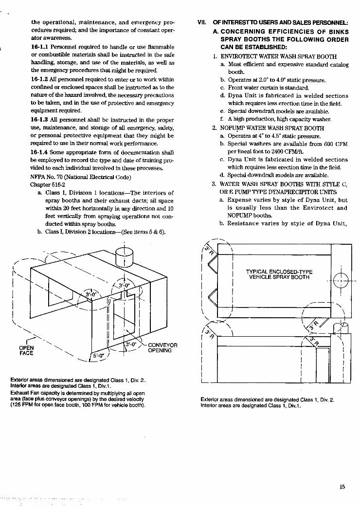
Exterior areas dimensioned are designated Class 1, Div. 2.. Interior areas are designated Class 1, Div.1. Exhaust Fan capacity is determined by multiplying all open area (face plus conveyor openings) by the desired velocity (125 FPM for open face booth, 100 FPM for vehicle booth).
, \
\
I
I I
I TYPICAL ENCLOSED-TYPE VEHICLE SPRAY BOOTH - I
I I /
Exterior areas dimensioned are designated Class 1, Div. 2. Interior areas are designated Class 1, Div.1.
15 .. . . . . ..
but can be stated to range from .9" to 1.3" static pressure.
(1) 'C' Style-900-2000 CFWft. Has a high level air intake. Ideal for special height spray booths. Our most versatile pump- type unit.
(2) ' E Style-900-1250 CFM/ft. Our most popu- lar cross draft, pump-type Dyna Unit. Catalog item. Economical in standard form.
c. Lineal feet capacities
4. AUTOMOTIVE SPRAY BOOTHS DOWN DRAFT SPRAY BOOTHS Air is introduced and forced through filters at the top of the booth. The air flows over the vehicle, around the sides and is pulled downward through the filter beneath the grating. With this downdraft method the overspray has less opportunity to adhere and spoil the finish. DOWN DRAFT SPRACURE BOOTHS Same airflow principle as the Downunder spray booth and the booth is equipped with heaters strategically positioned for proper curing of the coating. Special interlocks are provided for the spraying and curing cycles.
Note: The automotive washers mentioned above are seldom encountered outside the auto industry and are sized and priced to each specification. c. Dry, Filter Q p e Spray Booths
Pad (1) slightly more efficient (2) slightly more expensive
(1) longer lasting filter d. Pleated Filter Booth
Note: Down/Draft booths are available in either a dry or water wash coniiguration. A downdraft booth is expensive, but is also the most efficient booth arrangement available.
6. SPECIAL USE SPRAY BOOTHS Slimline "WH" Booth (1) A specialty booth for the furniture industry. (2) For low production use.
B. Air Supply Systems Direct-Fire Systems Energy Sources a. Natural gas-Least expensive when available b. LP gas-Requires storage system c. Steam-Noticeably more expensive than gas d. Electric-Prohibitively expensive
Units operate with heating element in the air stream.
C. Indirect-Fire System Energy Source . Oil-Unit is expensive. Oil requires a storage
and circulating system. Units do not have modulating control comparable to direct- fire units. Frequently have only "Full-half- off modulations.
VIII. GLOSSARY OF TERMS USED WHEN DESCRIBING SPRAY BOOTHS Air Make-up System-This is required to bring in clean filtered (humidified) air to replace the air that the exhaust fan has removed. Pleated Filter (Andreae)-A fire retardant filter consisting of two sheets of perforated corrugated paper of unequal size which is attached at the corruga- tions. The filter is collapsible and folds up like an accordion. When opened it provides a winding passage so that the contaminated air strikes the walls of the fil- ter causing the paint to stick or drop out of the air before being exhausted. This filter is also disposable. Baffle Booth-The simplest form of spray booth which uses baffles to distribute the are evenly through the spray area. Bench Spray Booth-The work area has been elevated above the floor to table height. This type spray booth is used to spray small items.
Booth Resistance-The rating is determined by the pressure differential across the eliminator section and is measured in inches of water column.
Booth Scraper-A device made of bronze so it will not create a spark when used in scraping the heavy build-up of dried paint off the walls of the spray booth. Canopy Booth-Where a cover is placed over a spraying process requiring the removal of contaminat- ed air. Ceramic-Type Spray Booth-A special type of spray booth used where ceramic type materials are used and which permits the reclamation of the overspray if so desired. Compound-Additives added to the water which causes the paint particles to either float on the surface or sink depending on the type booth being used. Reputable paint manufacturers are usually able to pro- vide the proper compound for their materials. When using a high resistance booth compounds should be kept to a minimum to avoid foaming. Heavy weight oil may at times be used to minimize foaming. Conveyor Opening-An opening in a spray booth which permits work to be carried through.
Cross Draft-Where the air enters from one side of the booth and the exhausted air is removed from the other side. Decibels (DB)-A unit of measuring the relative loud- ness of sound ordinarily detectable by the human ear. The measuring scale begins with number one for the faintest audible sound one can hear.
Dispo-Spray Booth-A spray booth with a cloth filter which traps overspray.
DowdDraft Water Wash Spray Booth-Thb spray booth removes the overspray and paint fumes through a grating on the floor. This is the cleanest spray booth available for doing h e finishing.
16 ..
- '
I
.: .
Draft Gauge-A device used to measure the pressure differential across the filter bank and indicates when it is time to change the filters.
Eliminator Section-The part of the booth where the solid particles are removed from the exhausted air.
Exhaust Chamber-A device to convert the enclosure such as a fireproof room into a spray area.
Exhaust Fan-The fan is used to provide sufficient pressure to move the required amount of air through the spray booth and maintain s a c i e n t air velocity.
Explosion Proof Lights-Lights which are used in areas where dangerous vapors are present which can cause an explosion or fire.
Explosion Proof Motor-A specially built motor which can be operated in a location where solvent fumes are present. In some states this type motor is required on all spray booths.
Filter Door-A door fitted with filters which are used to convert a room or spray booth into a dust free spray paint area.
Filter or Dry Booth-A spray booth with fire-proof disposable paper filters which trap overspray particles before the air is exhausted to the outside.
Filtration Eff iciency-Good filtration is predicated on the spraying of one gallon of paint per foot of booth three feet from the eliminator section using standard pressures for one hour. The exhausted air is sampled and not more than five grains of a particular type parti- cle are to be present in 1000 C.F.M. of air.
High Temperature Exhaust Fans-An exhaust fan designed with a special shaft and bearings to with- stand temperatures from 40°F to 400°F
Low Resistance Washers-Operate with a water col- umn indication below 2". Most standard type booths are low resistance because they are generally lower in cost and lower in operating cost.
High Resistance Washers-Operate with a water column indication above 2". The higher the resistance the better the filtration capabilities of the booth and the higher the operating cost.
No-Pump Water Wash Spray Booth-A spray booth that uses high air turbulence to maintain a water wash- ing action.
Manifold-The pipe which distributes the water to form the water curtain in the eliminator section of the spray booth.
Pad Filter (Paint Arrestor)-A honey combed fire retardant paper filter which traps the paint overspray, used on filter type spray booths, this item is disposable.
Open-Type Motor-ONE TYPE MOTOR WHERE its inner parts are exposed to the outside atmosphere.
Plenum Chamber-An area in which the pressure of the air in an enclosed space is greater than the outside atmosphere.
Semi-Draft Spray Booth-Where the air enters from the top and is exhausted through one of the sides. The spray operator should orient himself so that the over- spray is not pulled toward him.
Spray Booth-An area designed to carry off over- spray and fumes by means of exhausting the air from a spray area
Static Pressure-The amount of resistance which is present in any spray booth exhaust system. Static pressure varies with the amount of air being moved and its velocity, length of stack, elbows, filters, etc., anything that will cause restriction.
Totally Enclosed Motor-This motor is sealed in so that moisture and paint particles cannot reach the inside workings of the motor. Recommended to be used on spray booths where explosion-proof motors are not required to conform to (Factory Mutual) requirements.
Stripable Coating (Booth Coating)-A coating sprayed on the walls of the spray booth before it is used. This coating will simplify the removal of paint build-up caused by overspray.
Touch-Up Spray Booth-This is a very small type bench spray booth used to spray very small items. Not recommended for production.
Turntable-A rotating table to provide access to all sides of your product.
Up-Draft-Where the air enters from the bottom of the booth and is exhausted from the top.
Vapor Tight Lights-One type of lights that are enclosed so that dangerous vapors are kept from the wiring of the light fixture.
Varsol-Type Spray Booth-A specially built spray booth for solvent degreasing and cleaning of parts in a booth. Solvents are reclaimed and recirculated.
Water-Wash Spray Booth-A spray booth that has a water curtain which carries the overspray particles into a collecting pan. This spray booth removes a large quantity of overspray particles from the air. It is also the safest method known to prevent fires.
Weir Plate-A plate which holds the sludge in front of the booth or in a holding area so that the overspray paint particles may be removed.
Woven Polyester (Paint Pockets)-A high efficiency/ high capacity filter media for dry filter spray booths.
17

Space within the spray booth on the downstream and upstream sides of filters shall be protected with r approved automatic sprinklers.
SPRAY BOOTH
MAJOR MANDATORY REQUIREMENTS
A f Exhaust
fan
Filter DlsDosal. All discarded filter pads and filter rolls shall be immediately re- moved to a safe, well detached location or placed in a water-tilled metal con- tainer and disposed of at the close of the day's operation unless maintained completely in water.
b h a u s t Air Velocitv. The average air velocity over the open face of the booth (or booth cross section during spraying operations) shall be not less than 100 linear feet per minute. Electrostatic spraying operations may be conducted with an air velocity over the open face of the booth of not less than 60 linear feet per minute.
18
c
Top outlet exhaust fan (Inside building)
-Locate right hand I / outlet tuba in back of arrestor bank (7/16 dla. hole)
-Locate left hand outlet in front of arrestor bank (7/16 dia. hole)
For mounting the manometer housing, drill two 5/32 holes on 6 7 / ~ ~ centers for no. 10 sheet metal scr.
Frontal area, Each spray booth having a front area larger than 9 square feet shall have a metal deflector or curtain not less than 2'/2 inches deep installed at the upper outer edge of the booth over the opening.
Interiors, The interior surfaces of spray booths shall be smooth.
Spray booths shall be substantially con- structed of steel not thinner than No. 18, U.S. gauge, securely and rigidly sup- ported, or of concrete or masonry, except that aluminum or other substantial non- combustible material may be used for intermittent or low volume spraying. Spray booths shall be designed to sweep air currents toward the exhaust outlet.
Manometers. Visible gauges or audible alarm or pressure activated devices shall be installed to indicate or insure that the required air velocity is maintained.
Dlscharae clearance. Unless the spray booth exhaust duct terminal is from a water-wash spray booth, the terminal discharge point shall be not less than 6 feet from any combustible exterior wall or roof nor discharge in the direction of any combustible construction or unpro- tected opening in any noncombustible exterior wall within 25 feet.
Access door& When necessary to facilitate cleaning, exhaust ducts shall be provided with an ample number of access doors.
Minimum seoaratlon, There shall be no open flame or spark producing equipment in any spraying area nor within 20 feet thereof, unless separated by a partition.
c
9 . d
SELECTING A SPRAY MWW What to consider in selecting a spray booth. MATERIALS SPRAYED. The viscosity, drying speed, corrosive- ness, and abrasiveness of the material must be taken into account when specifying a spray booth. METHOD OF SPRAYING. How the material is sprayed is another factor because of the different degree of overspray which each method produces. There are three basic spray application techniques: Air Atomizatiofligh Volume Low Pressure. The paint particles ride on an air stream from spray gun to product being painted. Alrless AtomizationlAir Assisted Airless (Further atomized with air in air assisted process.) The material is atomized by hydraulic pressure. Electrostatic Spraying. Material atomization may be either air or airless. But, deposition of paint on the product being sprayed is by electrical attraction of the paint particles which have been charged with the opposite polarity from that of the product. PRODUCTION RATES. The quantity of overspray material that must be removed is a condition that also governs the size and performance requirements of the booth. This condition is directly related to the number of spray guns being used and to whether such use is continuous or intermittent and, if intermittent, to what interval. STANDARD VS CUSTOM. There will be instances where plant layout, product size, and other factors will require that a spray booth be custom engineered. However, in the mejority of cases, one of the many types and styles of standard spray booths will serve very satisfactorily. Standard booths have the advantages of ready availability and lower installed costs. CODE REQUIREMENTS. Spray booths and supplied components are designed to meet NFPA, OSHA, NEC and EPA regulations However, fire, building, and electrical codes vary from state to state, county to county, and city to city. To ensure compliance local codes should be reviewed with the authority having jurisdic- tion (h marshal, city inspector, etc.) Your distributor sales representative, or branch office will gladly answer all questions concerning booth selection and its relation- ship to a specific material application and production rate requirement. After you have made your selection, engineering staff stands ready to advise and assist you in planning your OSHA-approved work practices for operation and maintenance of this equipment. Why use a spray booth? SAFETY OF PERSONNEL AND PROPERTY. The spray booth provides a working environment that is clean and fume free-in some cases spray painters may not use face masks. Employee relations and productivity benefit directly and continuously. The rapid and thorough removal of volatile paint, solvent, and vehicle fumes from the premises prevents their accumulation and concentration to hazardous levels. The correct selection and installation of spray booths assures approval by occupational and safety health authorities (OSHA) and prime consideration for preferred insurance rates. QUALITY ASSURANCE OF PRODUCT FINISH. The air moving through the spray booth carries paint overspray away from the product, avoiding the finish-marring consequences of semi-dry paint particles setting on already-painted surfaces. With well- engineered mass air flow and directional characteristics, a spray booth very tangibly promotes product quality. POLLUTION REDUCTION OF OUTDOOR ATMOSPHERE. By effectively removing paint particles from the air being discharged to the outside, the spray booth reduces air pollution. This has very red significance for plant management. It fosters and maintains good relations with neighbors and with the community. It avoids risking violations of legal requirements. And it prevents paint staining and dirtying of immediately adjacent property.
< p“.
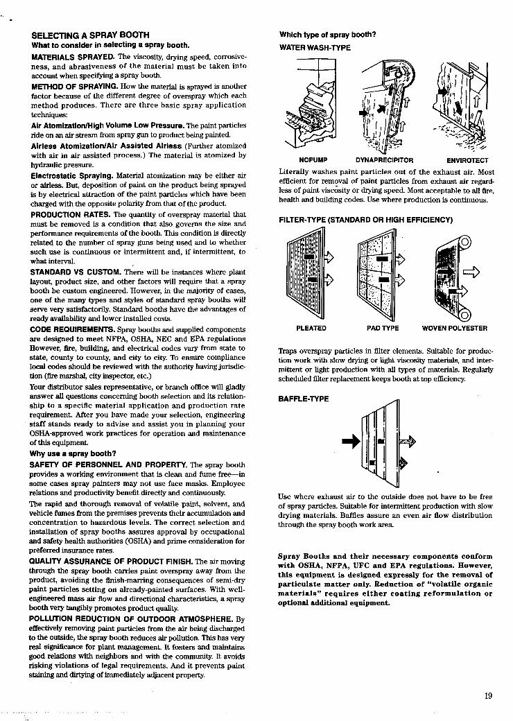
Which type of spray booth?
WATER WASH-TYPE
NOPUMP DYNAPRECIPITOR ENVIROTECT
Literally washes paint particles out of the exhaust air. Most efficient for removal of paint particles from exhaust air regard- less of paint viscosity or dqmg speed. Most acceptable to all fire, health and building codes. Use where production is continuous.
FILTER-TYPE (STANDARD OR HIGH EFFICIENCY)
PLEATED PAD TYPE WOVEN POLYESTER
Traps overspray particles in filter elements. Suitable for produc- tion work with slow drying or light viscosity materials, and inter- mittent or light production with all types of materials. Regularly scheduled filter replacement keeps booth at top efficiency.
BAFFLE-TYPE
I)
Use where exhaust air to the outside does not have to be free of spray particles. Suitable for intermittent production with slow drying materials. Baffles assure an even air flow distribution through the spray booth work area.
Spray Booths and their necessary components conform with OSHA, NFPA, UFC and EPA regulations. However, this equipment is designed expressly for the removal of par t iculate mat te r only. Reduction of “volatile organic m a t e r i a l s ” r e q u i r e s either coa t ing re formula t ion o r optional additional equipment.
19

0 South Edmonton
"JO Cleveland Chicago 0
Pittsburgh 0 0 Philadelphia 0
Indianapolis
0 Denver 0 St. Louis
Service ... Where you want it, when you need it.
0 Atlanta I
A comprehensive network of select jobber specialists stands ready to take care of your spray equipment needs. They await your inquiry and are prepared to add their years of experience,to the information supplied in this literature.
Branch Offices With Warehouse Facilities Atlanta, GA 5575 Spalding Dr., Norcross, GA 30092-2559 . . . .404/447-5600 Chicago, IL 9201 Belmont Ave., Franklin Park, IL 601 31 -2887 708/671-3000 Cleveland, OH 6909 Engle Rd., Bldg. C, Units 31,32,
Cleveland, OH 44130-3421 . . . . . . . . . . . . . . . . . . . . . . . . . . . .216/891-8181 Dallas, TX 14340 Proton Rd., Fanners Branch, TX 75244-3594 214/233-2500 Detroit, MI 11 996 Merriman Rd., Livonia, MI 48150-1 991 . . . . .313/525-6900 Los Angeles, CA 1405 Pioneer Street, Brea, CA 92621 -3721 . .310/691-1900 Milwaukee, WI 12705 Robin In., Brookfield, WI 53005-31 25 . . .414/781-6880
New York, NY 1 Chapin Rd., Pine Brook, NJ 07058-9719 201/575-666( Philadelphia, PA
4301 Rising Sun Ave., Philadelphia, PA 191 40-271 9 . . . .215/329-780( Pittsburgh, PA Pittsburgh Spray Equipment Co.
3601 Library Rd., Pittsburgh, PA 15234-2230 . . . . . . . . .412/882-455( San Francisco, CA 1459 San Mateo Ave.,
South San Francisco, CA 94080-6572 . . . . . . . . . . . . . . .415/589-847; Seattle, WA 1749 First Ave., S., Seattle, WA 981 34-1 441 . .206/623-135(
Branch Offices Denver, CO 7355 E. Orchard Rd., Suite 300, Indianapolis, IN 500 Polk St., Suite 15,
St. Louis, MO 1725 Larkin Williams Rd., Englewood, CO 801 11 -251 1 . . . . . . . . . . . . . . . . . . . . . . . . . .303/220-5532 Greenwood, IN 461 43-1 631 . . . . . . . . . . . . . . . . . . . . . . .317/888-7100
Fenton, MO 63026-2082 . . . . . . . . . . . . . . . . . . . . . . . . . .314/349-6655
Sales Offices Annaoolis. MD P.O. Box 41 75.21403-6175. . . . . . . . . . . . . . . . . .410/269-4104 Nashville. TN 2913 22nd Ave.. S.. 3721 5-1 203. . . . . . . . . . . .615/298-4736 Canandaigua, NY 136 Holiday Lane, 14424-1 724. . . . . . . . . . . .716/396-9533 Charlotte, NC 333 U Circle Avenue, 28207-1440 . . . . . . . . . . . . .704/522-4376 Concord, MA 85 Main St., 01742-2503. . . . . . . . . . . . . . . . . . . . . .617/542-8437 Des Moines, IA P.O. Box 23098,50325-9407 . . . . . . . . . . . . . . . .515/223-4777 Dublin, OH P.O. Box 831,4301 7-0831 . . . . . . . . . . . . . . . . . . . . . .614/262-5335 Grand Rapids, MI P.O. Box 721 6
Seymour Square Station, 4951 0-721 6. . . . . . . . . . . . . . . . . . . . .616/456-7106 Houston, TX 3910 FM 1960 West, Ste. 230,77068 . . . . . . . . . . .713/586-9990 Lindale, TX 307 Texas Dr., 75771 -5209 . . . . . . . . . . . . . . . . . . . . .214/595-5837 Little Rock, AR P.O. Box 2658,72203-2658 . . . . . . . . . . . . . . . . .501/376-9655 Louisville. KY . . . . . . . . . . . , . . . . . . . . . . . . . . . , , . . . . . . . . . . , . . . .502/425-5511 Mesa, Az.4016 East Downing, 85205 . . . . . . . . . . . . . . . . . . . . . . .602/924-4411 Metairie, LA 4621 Reich St., 70002-2241 . . . . . . . . . . . . . . . . . . . .504/486-2528
Domestic Subsidiaries Binks Research and Development Corp.
Sames Electrostatic, Inc. 1791 Range St., Boulder, CO 80301 -271 4 . . . . . . . . . . . . . . . . .303/443-2140
1 1998 Merriman Rd.. Livonia, MI 481 50-1 91 9. . . . . . . . . . . . . .313/261-5970 Divisions Poly-Craft Systems, Division of Binks Manufacturing Company
Sunkiss USA, 195 Palmer Avenue, Cottage Grove, OR 97424-9518.. . . . . . .216/891-8181
Division of Binks Manufacturing Co.
Norfolk, VA 400 Gresham Dr.,'23507-1901 . . . . . . . . . . . . . . .804/627-5685 N. Miami Beach, FL P.O. Box 601014,33160-1014 . . . . . . .305/949-0601 Overland P a 4 KS 9701 Hardy, 6621 2-3357 . . . . . . . . . . . . .816/471-6966 Ponte Vedra Beach, FL 899 Jetty Court, 32082-271 8 . . . . .904/724-2112 St. Paul, MN 1821 University Ave., 551 04-2801 . . . . . . . . . . .61 W645-5885 Salt Lake Ci, UT 3783 S. 5th St. W., No. 3,841 15-4256.. 801/268-9568 San Antonio, TX 931 5 Loma Doone St., 78250-2235 . . . . . .512/680-1206 Syracuse, NY 3650 James St., 13206-2451 . . . . . . . . . . . . . .315/476-3725 Tampa. FL 1221 N. Florida Ave., Suite A, 33602-3305 . . . . .813/236-0341 Toledo, OH P.O. Box 5894,4361 3-0894 . . . . . . . . . . . . . . . . .419/471-0905 Vancouver, WA 12205 Northeast 74th St., 98682-471 0.. . .206/260-1886 Vernon, CT 230 Hartford Tpke., 06066-4701 . . . . . . . . . . . . .203-875-8906 Winston-Salem, NC 206 Spmce St., Suite 16,27101-2736 919R23-4590 Canadian Sales & Division Offices Toronto, Ontario, 14 Vansco Rd., M8Z 5J5 (Headquarters) 4161252-5181
Montreal, Quebec, 6412 Trans-Canada Hwy., H4T 1x4 . . .514/731-4000
South Edmonton, Alberta, 1221 78th Ave., T6P 1 L8 . . . . . .403/440-4722
Sunkiss Canada, Division of Binks Manufacturing Co. of Canada Ltd., 6412 Trans-Canada Hwy., Montreal, Quebec, H4T 1x4.. 514/735-5488
Vancouver, British Columbia, 8584 Fraser St., V5X 3Y3. . .604/324-4671 9201 Belmont Ave.. Franklin Park, IL 601 31 -2887 . . . . . . . . . .708/671-3000
Foreign Subsidiaries with Warehouse Facilities
Binks Manufacturing Co. of Canada, Ltd.
Binks de Mexico, S.A. de C.V., Floresta No. 104 Colonia.
Binks-Bullows, Ltd., Pelsall Rd., Brownhills,
Binks-Bullows Sweden AB, Box 90, OgHrdesvagen 6C,
Binks-Bullows (Aust.) Pty. Ltd.. 5-7 By The Sea Road
Binks (Deutschland) GmbH., Lahnstrasse 31
Binks International, SA., Chaussb de Bruxelles 684
Binks International (Mia) S.r.l.,
Binks International France* ZAC de la Vallb 28.
Binks Japan, Ltd., Shuwa Kioicho TBR Bldg.
Sames. SA., Chemin de Malacher, ZIRST.
*Branch sales office of Binks International, SA.
14 Vansco Rd., Toronto, Ontario M8Z 5J5.. . . . . . . . . . . . . . . .416/252-5181
Claverh, Delegacion Azcapotzalco Mexico02090 D.F., Mexico 525/399-6045
Walsall, Staffordshire, WS8 7HW, England.. . . . . . . . . . . . . . .44 543-372571
44322, Partille, Gothenburg, Sweden.. . . . . . . . . . . . . . . . . . . .46 31-44-0720
Mona Vale, N.S.W., 2103, Australia . . . . . . . . . . . . . . . . . . . . . . .61 299-75066
45478 MulheidRuhr 1 Speldorf, Germany.. . . . . . . . . . . . . .49 208/99915-0
6-1410, Waterloo, Belgium.. . . . . . . . . . . . . . . . . . . . . . . . .32 W384 80 45
Via Amsterdam, 15-24040, Zingonia (Bergamo), Italy. . .39 35/88 22 64
rue Antoine Lavoisier F 77680 Roissy en Brie, France.. 33 1 60 28 33 55
Room 91 9, No. 7. =home, 81 (03) 527 53251 Kojimachi, Chiyoda-Ku, Tokyo 102, Japan.. . . . . . . . . . ... or 3252/3203
38240 Megan-France.. . . . . . . . . . . . . . . . . . . . . . . . . . . . . .33 76 41 60 30
Binks Manufacturing Company 0 9201 W. Belmont Ave., Franklin Park, IL 60131 0 Telephone (708) 671-3000