Embed Size (px)
Citation preview

National Aeronautics and Space Administration
Lewis Research CenterCleveland, Ohio 44135
NASAReferencePublication1370
Vincent R. Lalli, Robert E. Kastner, and Henry N. Hartt
January 1997
Training Manual for Elements of InterfaceDefinition and Control
National Aeronautics and Space Administration
Office of Management Scientific and Technical Information Program
NASAReferencePublication1370
1997
Vincent R. LalliLewis Research CenterCleveland, Ohio
Robert E. KastnerVitro CorporationRockville, Maryland
Henry N. HarttVitro CorporationWashington, DC
Training Manual for Elements of InterfaceDefinition and Control
NASA RP–1370 iii
PrefaceThis technical manual was developed under the Office of Safety and Mission Assurance continuous
training initiative. The structured information contained in this manual will enable the reader to efficiently andeffectively identify and control the technical detail needed to ensure that flight system elements mate properlyduring assembly operations (both on the ground and in space).
Techniques used throughout the Federal Government to define and control technical interfaces for bothhardware and software were investigated. The proportion of technical information actually needed toeffectively define and control the essential dimensions and tolerances of system interfaces rarely exceeded 50percent of any interface control document. Also, the current Government process for interface control is verypaper intensive. Streamlining this process can improve communication, provide significant cost savings, andimprove overall mission safety and assurance.
The primary thrust of this manual is to ensure that the format, information, and control of interfacesbetween equipment are clear and understandable, containing only the information needed to guaranteeinterface compatibility. The emphasis is on controlling the engineering design of the interface and not on thefunctional performance requirements of the system or the internal workings of the interfacing equipment.Interface control should take place, with rare exception, at the interfacing elements and no further.
There are two essential sections of the manual. The first, Principles of Interface Control, discusses howinterfaces are defined. It describes the types of interface to be considered and recommends a format for thedocumentation necessary for adequate interface control. The second, The Process: Through the Design Phases,provides tailored guidance for interface definition and control.
This manual can be used to improve planned or existing interface control processes during system designand development. It can also be used to refresh and update the corporate knowledge base. The informationpresented herein will reduce the amount of paper and data required in interface definition and control processesby as much as 50 percent and will shorten the time required to prepare an interface control document. It alsohighlights the essential technical parameters that ensure that flight subsystems will indeed fit together andfunction as intended after assembly and checkout.

This Page Intentionally Left Blank

This Page Intentionally Left Blank
NASA RP–1370 vi
ContentsChapter1. Introduction . . . . . . . . . . . . . . . . . . . . . . . . . . . . . . . . . . . . . . . . . . . . . . . . . . . . . . . . . . . . . . . . . . . . . . . . 1
1.1 Training . . . . . . . . . . . . . . . . . . . . . . . . . . . . . . . . . . . . . . . . . . . . . . . . . . . . . . . . . . . . . . . . . . . . . . . . 2
2. Principles of Interface Control . . . . . . . . . . . . . . . . . . . . . . . . . . . . . . . . . . . . . . . . . . . . . . . . . . . . . . . . . 32.1 Purpose of Interface Control . . . . . . . . . . . . . . . . . . . . . . . . . . . . . . . . . . . . . . . . . . . . . . . . . . . . . . . . 32.2 Identifying Interfaces . . . . . . . . . . . . . . . . . . . . . . . . . . . . . . . . . . . . . . . . . . . . . . . . . . . . . . . . . . . . . . 32.3 Categorizing (Partitioning) and Defining Interfaces . . . . . . . . . . . . . . . . . . . . . . . . . . . . . . . . . . . . . . 4
2.3.1 Electrical/Functional . . . . . . . . . . . . . . . . . . . . . . . . . . . . . . . . . . . . . . . . . . . . . . . . . . . . . . . . . 42.3.2 Mechanical/Physical . . . . . . . . . . . . . . . . . . . . . . . . . . . . . . . . . . . . . . . . . . . . . . . . . . . . . . . . . . 42.3.3 Software . . . . . . . . . . . . . . . . . . . . . . . . . . . . . . . . . . . . . . . . . . . . . . . . . . . . . . . . . . . . . . . . . . . 52.3.4 Supplied Services . . . . . . . . . . . . . . . . . . . . . . . . . . . . . . . . . . . . . . . . . . . . . . . . . . . . . . . . . . . . 5
2.4 Documenting Interfaces . . . . . . . . . . . . . . . . . . . . . . . . . . . . . . . . . . . . . . . . . . . . . . . . . . . . . . . . . . . . 62.5 Identifying Steady-State and Non-Steady-State Interfaces . . . . . . . . . . . . . . . . . . . . . . . . . . . . . . . . . 62.6 Selecting a Custodian . . . . . . . . . . . . . . . . . . . . . . . . . . . . . . . . . . . . . . . . . . . . . . . . . . . . . . . . . . . . . . 62.7 Analyzing for Interface Compatibility . . . . . . . . . . . . . . . . . . . . . . . . . . . . . . . . . . . . . . . . . . . . . . . . . 72.8 Verifying Design Compliance With Interface Control Requirement . . . . . . . . . . . . . . . . . . . . . . . . . . 72.9 Verifying Contract-Deliverable Item . . . . . . . . . . . . . . . . . . . . . . . . . . . . . . . . . . . . . . . . . . . . . . . . . . 72.10 Training . . . . . . . . . . . . . . . . . . . . . . . . . . . . . . . . . . . . . . . . . . . . . . . . . . . . . . . . . . . . . . . . . . . . . . . . 8
3. The Process: Through the Design Phases . . . . . . . . . . . . . . . . . . . . . . . . . . . . . . . . . . . . . . . . . . . . . . 133.1 Program Phases . . . . . . . . . . . . . . . . . . . . . . . . . . . . . . . . . . . . . . . . . . . . . . . . . . . . . . . . . . . . . . . . . 13
3.1.1 Concept Definition . . . . . . . . . . . . . . . . . . . . . . . . . . . . . . . . . . . . . . . . . . . . . . . . . . . . . . . . . . 133.1.2 Requirements Definition . . . . . . . . . . . . . . . . . . . . . . . . . . . . . . . . . . . . . . . . . . . . . . . . . . . . . 133.1.3 Systems Integration . . . . . . . . . . . . . . . . . . . . . . . . . . . . . . . . . . . . . . . . . . . . . . . . . . . . . . . . . 16
3.2 Preparing and Administering Interface Control Document . . . . . . . . . . . . . . . . . . . . . . . . . . . . . . . . 163.2.1 Selecting Types of Interface Control Document . . . . . . . . . . . . . . . . . . . . . . . . . . . . . . . . . . . 163.2.2 Tracking and Resolving Missing Interface Design Data . . . . . . . . . . . . . . . . . . . . . . . . . . . . . 16
3.3 Initial Issuance of ICD . . . . . . . . . . . . . . . . . . . . . . . . . . . . . . . . . . . . . . . . . . . . . . . . . . . . . . . . . . . . 173.4 Document Review and Comment . . . . . . . . . . . . . . . . . . . . . . . . . . . . . . . . . . . . . . . . . . . . . . . . . . . 17
3.4.1 Resolving Comments . . . . . . . . . . . . . . . . . . . . . . . . . . . . . . . . . . . . . . . . . . . . . . . . . . . . . . . . 173.4.2 Interface Control Working Group . . . . . . . . . . . . . . . . . . . . . . . . . . . . . . . . . . . . . . . . . . . . . . 173.4.3 Approval/Signoff Cycle . . . . . . . . . . . . . . . . . . . . . . . . . . . . . . . . . . . . . . . . . . . . . . . . . . . . . . 193.4.4 Technical Approval . . . . . . . . . . . . . . . . . . . . . . . . . . . . . . . . . . . . . . . . . . . . . . . . . . . . . . . . . 193.4.5 Baselining . . . . . . . . . . . . . . . . . . . . . . . . . . . . . . . . . . . . . . . . . . . . . . . . . . . . . . . . . . . . . . . . . 19
3.5 Change Notices . . . . . . . . . . . . . . . . . . . . . . . . . . . . . . . . . . . . . . . . . . . . . . . . . . . . . . . . . . . . . . . . . 193.5.1 Initiating Changes . . . . . . . . . . . . . . . . . . . . . . . . . . . . . . . . . . . . . . . . . . . . . . . . . . . . . . . . . . 193.5.2 Requesting Changes . . . . . . . . . . . . . . . . . . . . . . . . . . . . . . . . . . . . . . . . . . . . . . . . . . . . . . . . . 213.5.3 Proposed Change Notice Review and Comment Cycle . . . . . . . . . . . . . . . . . . . . . . . . . . . . . . 213.5.4 Processing Approved Changes . . . . . . . . . . . . . . . . . . . . . . . . . . . . . . . . . . . . . . . . . . . . . . . . . 213.5.5 Distributing Approved Changes . . . . . . . . . . . . . . . . . . . . . . . . . . . . . . . . . . . . . . . . . . . . . . . . 213.5.6 Configuration Control Board . . . . . . . . . . . . . . . . . . . . . . . . . . . . . . . . . . . . . . . . . . . . . . . . . . 213.5.7 Closing the Loop . . . . . . . . . . . . . . . . . . . . . . . . . . . . . . . . . . . . . . . . . . . . . . . . . . . . . . . . . . . 22
3.6 Training . . . . . . . . . . . . . . . . . . . . . . . . . . . . . . . . . . . . . . . . . . . . . . . . . . . . . . . . . . . . . . . . . . . . . . . 22

NASA RP–1370 vii
Appendixes:A: Electrical/Functional Interface Example . . . . . . . . . . . . . . . . . . . . . . . . . . . . . . . . . . . . . . . . . . . . . . 24B: Mechanical/Physical Interface Examples . . . . . . . . . . . . . . . . . . . . . . . . . . . . . . . . . . . . . . . . . . . . . . 29C: Software Interface Example . . . . . . . . . . . . . . . . . . . . . . . . . . . . . . . . . . . . . . . . . . . . . . . . . . . . . . . . 38D: Supplied Services Interface Example . . . . . . . . . . . . . . . . . . . . . . . . . . . . . . . . . . . . . . . . . . . . . . . . . 39E: Compatibility Analysis . . . . . . . . . . . . . . . . . . . . . . . . . . . . . . . . . . . . . . . . . . . . . . . . . . . . . . . . . . . . 43F: Bracket System for Interfaces . . . . . . . . . . . . . . . . . . . . . . . . . . . . . . . . . . . . . . . . . . . . . . . . . . . . . . . 46G: ICD Guidelines . . . . . . . . . . . . . . . . . . . . . . . . . . . . . . . . . . . . . . . . . . . . . . . . . . . . . . . . . . . . . . . . . . 48H: Glossary . . . . . . . . . . . . . . . . . . . . . . . . . . . . . . . . . . . . . . . . . . . . . . . . . . . . . . . . . . . . . . . . . . . . . . . 49
References . . . . . . . . . . . . . . . . . . . . . . . . . . . . . . . . . . . . . . . . . . . . . . . . . . . . . . . . . . . . . . . . . . . . . . . . . . . 50Bibliography . . . . . . . . . . . . . . . . . . . . . . . . . . . . . . . . . . . . . . . . . . . . . . . . . . . . . . . . . . . . . . . . . . . . . . . . . . 50Training Answers . . . . . . . . . . . . . . . . . . . . . . . . . . . . . . . . . . . . . . . . . . . . . . . . . . . . . . . . . . . . . . . . . . . . . . 51

NASA RP–1370 viii

NASA RP–1370 1
Establishing a system that ensures that all interface param-eters are identified and controlled from the initial designactivities of a program is essential. It is not necessary that thefine details of these parameters be known at that time, but it isvery important that the parameters themselves are identified,that everything known about them at that time is recorded andcontrolled, and that voids1 are identified and scheduled forelimination. The latter requirement is of primary importance tothe proper design of any interface. Initial bounding of a void andscheduled tightening of those bounds until the precise dimen-sions or conditions are identified act as a catalyst to efficientdesign and development. An enforced schedule for eliminatingvoids is one of the strongest controls on schedule that can beapplied (ref. 3).
The process of identifying, categorizing, defining, and docu-menting interfaces is discussed in the following chapter. Guid-ance for the analysis of interface compatibility is also provided.
Chapter 1
IntroductionThis technical manual resulted from an investigation of
techniques used throughout NASA and other Federal Govern-ment agencies to define and control technical interfaces forboth hardware and software. The processes described hereindistill the requirements for interface definition and control intoa concise set of parameters that control the design of only theinterface-related elements rather than providing extraneousdesign detail that must subsequently be configurationmanaged.
The purpose of this manual is to provide guidelines forestablishing and conducting the interface control process sothat items produced by different design agencies satisfactorilymate and operate in a way that meets mission requirements.These guidelines were drawn from the methodologies of anumber of highly successful programs and therefore representa compilation of “lessons learned.”
The principles and processes of interface definition andcontrol presented in this document apply to all projects andprograms but may be tailored for program complexity. Forexample, the interface control process may be less formal for aproject or program that requires only one or two end items andhas few participants; however, the formal interface controldocument is still necessary. For a project or program thatrequires a number of end items and where several participantsare involved, a carefully followed interface control process isimperative, with comments, decisions, agreements, and com-mitments fully documented and tracked. Individual managersshould provide the implementation criteria for their interfacecontrol processes early in the project or program (ref. 1).
This manual covers the basic principles of interface defini-tion and control: how to begin an interface control programduring the development of a new project or program, how todevelop and produce interface documentation, how to managethe interface control process, and how to transfer interfacecontrol requirements to hardware and software design.
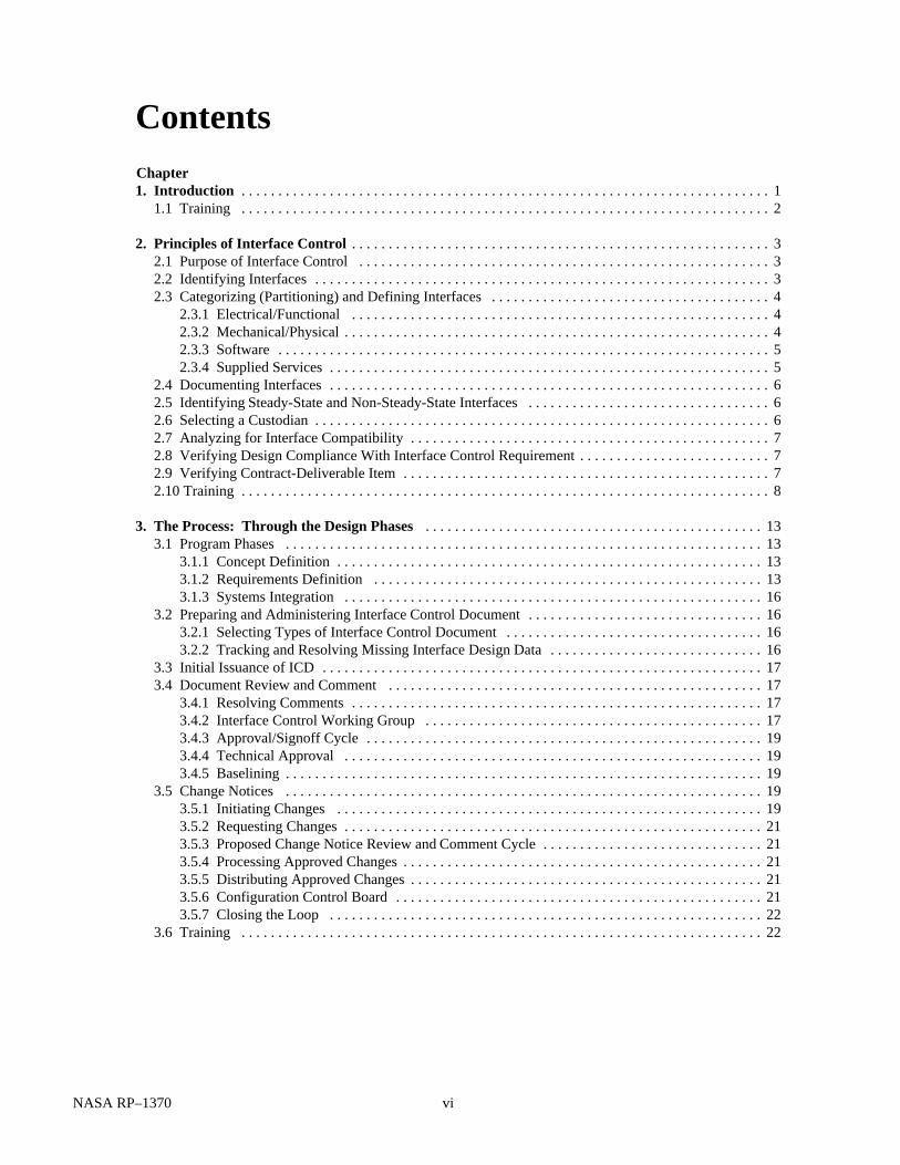
Interface definition and control is an integral part of systemengineering. It should enter the system engineering cycle at theend of the concept development phase. Depending on whetherthe system under development is designed for one-time orcontinuous use, the process may continue for the full life cycleof the system. Interface definition and control should not beequated to configuration management or configuration control.Rather it is a technical management tool that ensures that allequipment will mate properly the first time and will continue tooperate together as changes are made during the life cycle of thesystem. Figure 1.1 depicts the elements of the system engineer-ing cycle and is used in chapter 3 to describe the application ofthe interface discipline at different parts of the life cycle (ref. 2).
1A “void” is a specific lack of information needed for control of an interfacefeature. Control and elimination of voids is fundamental to a strong interfacedefinition and control program.
Figure 1.1—System engineering cycle. (The requirements definition phase must include the requirements for the interfaces as well as those which will eventually be reflected in the interface control document.)
Configuration management
Technical oversight
Verification and validation
Mission needs definition
Risk and systems analysis
Systems integration
Requirements definiton
Concept definition

2 NASA RP–1370
1.1 Training2
1. The processes explained in this manual for interfacedefinition and control areA. A concise set of parameters that control the design of the
interface-related elementsB. A set of design details needed for configuration manage-
ment
2. The process is very important for projects that requireA. A number of end itemsB. Involvement of several participantsC. Comments, decisions, agreements, and commitments
that must be fully documented and trackedD. All of the above
3. What elements does the system engineering cycle contain?A. Mission needs, requirements, and integrationB. Technical oversight, core design, and system configura-
tion
2Answers are given at the end of this manual.
C. Mission needs definition, risk and systems analysis,concept and requirements definitions, system integra-tion, configuration management, technical oversight,and verification and validation
4a. What is a void?A. Bracketed dataB. Wrong dataC. Lack of information needed
4b.How should voids be handled?A. Voids should be identified and their elimination
scheduled.B. Data should be analyzed.C. Supplier should be guided.
4c. Name a strong control needed for voids.A. Precise dimensionsB. Enforced scheduleC. Identified catalysts
NASA RP–1370 3
Chapter 2
Principles of Interface Control
2.1 Purpose of Interface Control
An interface is that design feature of a piece of equipment3
that affects the design feature of another piece of equipment.The purpose of interface control is to define interface require-ments so as to ensure compatibility between interrelated piecesof equipment and to provide an authoritative means of control-ling the design of interfaces. Interface design is controlled by aninterface control document (ICD).
These documents
1. Control the interface design of the equipment to preventany changes to characteristics that would affect compat-ibility with other equipment
2. Define and illustrate physical and functional characteris-tics of a piece of equipment in sufficient detail to ensurecompatibility of the interface, so that this compatibilitycan be determined from the information in the ICD alone
3. Identify missing interface data and control the submis-sion of these data
4. Communicate coordinated design decisions and designchanges to program participants
5. Identify the source of the interface component
ICD’s by nature are requirements documents: they definedesign requirements and allow integration. They can causedesigns to be the way they are. They record the agreed-to designsolution to interface requirements and provide a control mecha-nism to ensure that the agreed-to designs are not changed by oneparticipant without negotiated agreement of the other participant.
To be effective, ICD’s should track a schedule path compat-ible with design maturation of a project (i.e., initial ICD’sshould be at the 80% level of detail at preliminary designreview, should mature as the design matures, and should reachthe 99% mark near the critical design review).
2.2 Identifying Interfaces
Identifying where interfaces are going to occur is a part ofsystems engineering that translates a mission need into aconfigured system (a grouping of functional areas) to meet thatneed. Each functional area grouping is assigned certain perfor-
mance requirements. These performance requirements are trans-lated into design requirements as the result of parametricstudies, tradeoff studies, and design analyses. The designrequirements are the basis for developing the system specifica-tions. The boundaries between the functional areas as definedin the system specifications become the interfaces. Early inter-face discussions often contribute to final subsystem specifica-tions. Interface characteristics, however, can extend beyond theinterface boundary, or interface plane, where the functionalareas actually come together. The interface could be affectedby, and therefore needs to be compatible with, areas thatcontribute to its function but may not physically attach. Forexample, it may be necessary to define the path of a piece ofequipment as it traverses through another piece of equipmentand rotates and articulates to carry out its function. Electricalcharacteristics of a transmitter and receiver separated by aninterface plane may have to be defined for each to properlyfunction. Similarly, the acoustic energy produced by one com-ponent and transmitted through the structure or onto anothercomponent may need a corresponding definition.
Identifying interfaces early in a program is essential tosuccessful and timely development. Functional analyses areused for analyzing performance requirements and decompos-ing them into discrete tasks or activities (i.e., decomposing theprimary system functions into subfunctions at ever increasinglevels of detail). Functional block diagrams are used to definedata flow throughout the system and interfaces within thesystem. Once the segments and elements within a system havebeen defined, a top-level functional block diagram is prepared.The block diagrams are then used in conjunction with N-squared diagrams to develop interface data flows. The N-squared diagram is a technique used extensively to develop datainterfaces but can also be refined for use in defining hardwareinterfaces. However, use of this tool in this manual will berestricted to interface categorization. Additional description isprovided in section 3.1.1.
In summary, identifying where interfaces are going to occurbegins the systems integration component of systems engineer-ing and must start early in design planning. The interfaceboundaries or planes vary from program to program dependingon how design and development responsibilities are assigned.Interface control can occur within a functional area of otherdesign and development agents. Therefore, interfaces can beidentified at many levels, for example,
1. Center to center2. Discipline to discipline (e.g., propulsion to guidance,
sensor to structure, or power to users)3. Contractor to contractor
3For purposes of this manual, a piece of equipment is a functional area assignedto a specific source. Thus, a piece of equipment can be an element of the spacestation, a system of a spacecraft, a work package assigned to a contractor, or asubsystem.

4 NASA RP–1370
4. Center to contractor to discipline5. Program to program (e.g., shuttle to National Launch
System)
Once interface boundaries or planes are established, theinterfaces must be categorized and defined.
2.3 Categorizing (Partitioning) and Defining Interfaces
Categorizing, or partitioning, interfaces separates the inter-face features by technical discipline and allows each category,in most cases, to proceed through the definition processindependently.
The following basic interface categories (defined by thetypes of feature and data they encompass) are recommended foruse in most programs:
1. Electrical/functional2. Mechanical/physical3. Software4. Supplied services
During the early phases of systems engineering, interfacesmay be assigned only the high-level designation of thesecategories. As the system becomes better defined, the details ofthe physical and functional interface characteristics becomebetter defined and are documented.
An interface can be assigned to one of these categories by anumber of processes of elimination. The one recommended foruse is the N-squared diagram (ref. 4), which is currently beingused by some NASA centers.
2.3.1 Electrical/Functional
Electrical/functional interfaces are used to define and con-trol the interdependence of two or more pieces of equipmentwhen the interdependence arises from the transmission of anelectrical signal from one piece of equipment to another. Allelectrical and functional characteristics, parameters, and toler-ances of one equipment design that affect another design arecontrolled by the electrical/functional ICD. The functionalmechanizations of the source and receiver of the interfaceelectrical signal are defined, as well as the transmissionmedium.
The interface definition includes the data and/or controlfunctions and the way in which these functions are representedby electrical signals. Specific types of data to be defined arelisted here:
1. Function name and symbol2. Impedance characteristics
3. Shielding and grounding4. Signal characteristics5. Cable characteristics6. Data definition7. Data transmission format, coding, timing, and updating8. Transfer characteristics9. Circuit logic characteristics
10. Electromagnetic interference requirements11. Data transmission losses12. Circuit protective devices
Other data types may be needed. For example, an analogsignal interface document would contain function name andsymbol, cable characteristics, transfer characteristics, circuitprotective devices, shielding, and grounding; whereas a digitaldata interface would contain function name and symbol, dataformat, coding, timing and updating, and data definition.
Additional data types under the electrical/functional headingare
1. Transmission and receipt of an electrical/electromag- netic signal
2. Use of an electrically conductive or electromagneticmedium
Appendix A shows recommended formats for electrical andfunctional interface control drawings.
2.3.2 Mechanical/Physical
Mechanical/physical interfaces are used to define and con-trol the mechanical features, characteristics, dimensions, andtolerances of one equipment design that affect the design ofanother subsystem. They also define force transmission re-quirements where a static or dynamic force exists. The featuresof the equipment that influence or control force transmissionare also defined in this ICD. Mechanical interfaces includethose material properties of the equipment that can affect thefunctioning of mating equipment, such as thermal and galvaniccharacteristics. Specific types of data defined are
1. Optical characteristics2. Parallelism and straightness3. Orientation requirements4. Space or provisions required to obtain access for perform-
ing maintenance and removing or replacing items,including space for the person performing the function
5. Size, shape, mass, mass distribution, and center of gravity6. Service ports7. Indexing provisions8. Concentricity 9. Surface finish
10. Hard points for handling

NASA RP–1370 5
11. Sealing, pressurization, attachment, and lockingprovisions
12. Location and alignment requirements with respect toother equipment
13. Thermal conductivity and expansion characteristics14. Mechanical characteristics (spring rate, elastic proper-
ties, creep, set, etc.)15. Load-carrying capability16. Galvanic and corrosive properties of interfacing
materials
Other data types may be needed. For example, an ICDcontrolling a form-and-fit interface would generally containsuch characteristics as size and shape of the item, location ofattachment features, location of indexing provisions, and weightand center of gravity of the item. However, an ICD controllinga structural load interface would contain weight and center ofgravity, load-carrying capability, and elastic properties of thematerial if applicable to the loading conditions. Not all ICD’scontrolling a form-and-fit interface would have to contain alltypes of data given in this example, but some form-and-fitinterface definitions contain more than the 16 types of datalisted. Indexing definitions may require angularity, waviness,and contour definitions and tolerances.
Additional data types under the mechanical/physical head-ing would be
1. Dimensional relationships between mating equipment2. Force transmission across an interface3. Use of mechanically conductive media4. Placing, retaining, positioning, or physically transporting
a component by another component5. Shock mitigation to protect another component
Appendix B (from ref. 5) shows a mechanical/physical draw-ing.
This extensive variety of possibilities and combinationsprevents assigning a standard set of data types or level of detailto a form-and-fit interface. Each interface must be analyzed andthe necessary controlling data identified before the proper levelof interface definition and control can be achieved. This holdstrue for all examples given in this chapter.
2.3.3 Software
A software interface defines the actions required wheninterfacing components that result from an interchange ofinformation. A software interface may exist where there is nodirect electrical interface or mechanical interface between twoelements. For example, whereas an electrical ICD might definethe characteristics of a digital data bus and the protocols usedto transmit data, a software interface would define the actionstaken to process the data and return the results of the process.Software interfaces include operational sequences that involve
multiple components, such as data-processing interactionsbetween components, timing, priority interrupts, and watchdogtimers. Controversy generally arises in determining whetherthese relationships are best documented in an electrical/func-tional ICD, a software ICD, or a performance requirementsdocument. Generally, software interface definitions include
1. Interface communication protocol2. Digital signal characteristics3. Data transmission format, coding, timing, and updating
requirements4. Data and data element definition5. Message structure and flow6. Operational sequence of events7. Error detection and recovery procedures
Other data types may be needed. Appendix C provides anexample of a software interface signal.
2.3.4 Supplied Services
Supplied services are those support requirements that a pieceof equipment needs to function. Supplied services are providedby an external separate source. This category of interface can besubdivided further into electrical power, communication, fluid,and environmental requirements. The types of data defined forthese subcategories are
1. Electrical power interface:a. Phaseb. Frequencyc. Voltaged. Continuitye. Interrupt timef. Load currentg. Demand factors for significant variations during
operationsh. Power factori. Regulationj. Rippleh. Harmonicsl. Spikes or transientsm. Ground isolationn. Switching, standby, and casualty provisions
2. Communication interface:a. Types of communication required between equip-
mentb. Number of communication stations per communica-
tion circuitc. Location of communication stations
3. Fluid interface:a. Type of fluid required
i. Gaseousii. Liquid

6 NASA RP–1370
b. Fluid propertiesi. Pressureii. Temperatureiii. Flow rateiv. Purityv. Duty cyclevi. Thermal control required (e.g., fluid heat lost or
gained)4. Environmental characteristic interface:
a. Ambient temperatureb. Atmospheric pressurec. Humidityd. Gaseous composition requirede. Allowable foreign particle contents
Other data types may be needed. Appendix D shows an ex-ample of a supplied services interface for air-conditioning andcooling water.
2.4 Documenting Interfaces
Once an interface has been categorized and its initial con-tents defined, that interface definition must be recorded in adocument that is technically approved by the parties (designerand manager) and the owners of both sides of the interface. Thedocument then is approved by the next higher level in theproject management structure and becomes the official controlfor interface design.
The program manager must ensure that compliance with theapproved interface control document is mandatory. Each levelof program management must ensure that the appropriatecontractors and Government agencies comply with the docu-mentation. Therefore, technical approval of the interface con-trol document indicates that the designated approvingorganization is ready to invoke the interface control documentcontractually on the approving organization’s contractor orsupporting organization.
The interface categories can be grouped together in onedocument, or each category can be presented in a separatedocument (i.e., electrical ICD’s, mechanical ICD’s, etc). Theformat for interface control documents is flexible. In most casesa drawing format is the easiest to understand and is adaptableto the full range of interface data.
The specification format (ref. 6) can also be used. The use ofthis type of format enables simple changes through the removaland insertion of pages; however, the format is often difficult touse when presenting complex interface definitions that requiredrawings, and normally requires many more pages to conveythe same level of information.
In either case there must be agreement on a standard for datapresentation and interpretation. ANSI standard Y14.5 (ref. 7)can be used for dimensions, along with DOD–STD–100
(ref. 8), for general guidance of a drawing format. The specifi-cation format should use MIL–STD–490 (ref. 6) for paragraphnumbering and general content.
Some large programs require large, detailed ICD’s. Main-taining a large, overly detailed document among multipleparties may be more difficult than maintaining a number ofsmaller, more focused documents. Grouping small documentsby major category of interface and common participants is oneof the most effective and efficient strategies. It minimizes thenumber of parties involved and focuses the technical disci-plines, greatly streamlining the decision process and permittingmuch shorter preparation time. However, interfaces can bemultidisciplinary and separate documents can result in mis-communications.
2.5 Identifying Steady-State and Non-Steady-State Interfaces
Interfaces can vary from a single set that remains constant forthe life of a program to a multiple set of documents thatreconfigures during specific events in the life of a system. Thefirst category would be used for an interplanetary probe. Theinterfaces of its instruments with the basic spacecraft structurewould remain the same from assembly for launch throughoutthe life of the experiment. However, a continually evolvingplatform, such as a lunar base, would perhaps be controlled ina series of interface documents based on the assembly sequenceof the base. An initial base would be established and later mademore complex with additional structures and equipment deliv-ered by subsequent lunar flights. Pressurized elements, logisticelements, power-generating sources, habitats, laboratories, andmining and manufacturing facilities might be added andreconfigured over time. Each configuration would require a setof interface control documents to ensure compatibility at theconstruction site as well as with the transportation mediumfrom Earth to Moon. Interfaces that remained constant duringthis process might be termed steady state and require no furtherconsideration once the interface was verified and delivered;whereas interfaces that would evolve from the initialconfiguration through multiple iterations would require multi-coordination of interface parameters and schedules. The selec-tion of interface categories should identify the steady-state ornon-steady-state nature of interfaces as well as their initialdesignations (ref. 9).
2.6 Selecting a Custodian
Selecting an ICD custodian can depend on several factors(e.g., percentage of interface ownership, relative mission im-portance of interface sides, and relative investment of interfacesides). However, it is generally most effective if the custodian

NASA RP–1370 7
selected has an objective point of view. An example of thiswould be someone who is independent of either side of theinterface (i.e., without any “vested interest” in the interfacehardware or software). Objectivity permits unbiased control ofthe interface, involvement of the custodian as an objectivemediator, and documentation of the interface on a noninterfer-ence basis with program/project internal design. Selecting anindependent interface custodian should be the first step inestablishing an interface control organization. A set of criteriashould be used to select the custodian by weighting the contentand interests of the interface with the needs of interface control.One set of criteria is as follows:
1. Integration center: Is one center accountable for integrat-ing the interfaces controlled by this ICD? This criterion isconsidered the most important because the integration centerwill have the final responsibility for certifying flight readinessof the interfaces controlled in the ICD.
2. U.S. center: Is the participant a U.S. center? This crite-rion is considered the next most important because of agencyexperience and projected responsibility.
3. Flight hardware or software: Is the interfacing articleflight hardware or software (as opposed to support hardware orsoftware)? Flight hardware or software takes precedence.
4. Flight sequence: Does one side of the interfacing equip-ment fly on an earlier manifest than the other? An earlier flightsequence takes precedence over follow-on interfacinghardware.
5. Host or user: Is the interfacing article a facility (asopposed to the user of the facility)? Procedure in this criterionis guided by the relative priority of the interfacing articles.
6. Complexity: How complex is the interfacing equipment(relative to each side)? The more complex side of the interfacenormally takes precedence.
7. Behavior: How active is the interfacing equipment? Theactive side normally takes precedence over the passive side.
8. Partitions: How are the partitions (categories) used by theinterfacing equipment? The relative importance of the parti-tions to the interface is acknowledged, and selection of thecustodian is sensitive to the most important partitiondevelopers.
Scores are assigned to each piece of interfacing equipmentfor each criterion. These scores can be determined by manydifferent methods. Discrete values can be assigned to the firstfour criteria. A score of 1.0 is assigned if the interfacing pieceof equipment is unique in meeting the criterion, the other pieceof equipment then receives a score of 0.0. Scores of 0.5 areassigned to both sides if both (or neither) of them meet thecriterion. There is no definitive way of assigning scores to thelast four criteria; however, verbal consensus or an unbiasedsurvey can be used to assign scores. Also, the partition criteriacan be scored by partition evaluation analysis (ref. 4).
2.7 Analyzing for Interface Compatibility
The interface definitions to be documented on the ICD’smust be analyzed for compatibility before the ICD is authenti-cated. Appendix E provides guidance on how compatibilityanalyses may be performed. They vary in their complexity froma simple inspection of the interface definitions to complexmathematical analyses where many variables are involved.
Regardless of complexity, the compatibility analysis shouldbe documented and maintained as backup information for theICD. It can be used to expedite any changes to the interfacedefinition by providing a ready means for evaluating thecompatibility of the proposed change. The compatibility analy-sis also can be used to document how the interface definitionwas arrived at and why the definition is presented as it is onan ICD.
2.8 Verifying Design Compliance With Interface Control Requirement
The ICD can only fulfill its purpose if the contractors’detailed design drawings and construction practices adhere tothe limits imposed by the ICD. Verifying compliance of thedesign as well as of the construction process is an integral partof interface control.
Each contractor should be assigned the responsibility ofdenoting on their manufacturing and inspection drawings ordocuments those features and characteristics that, if altered,would affect interfaces controlled by the ICD’s. To ensure thatall ICD requirements are covered, the contractor should select,at the highest assembly level at which the equipment is in-spected, the features and characteristics to be denoted. Anydesign change affecting an ICD-controlled feature or charac-teristic would be clearly identified even at the assembly level(ref. 10).
Entries identified as “to be resolved” (TBR) can be bracketedor shaded to indicate preliminary interface information or aninterface problem. This information is subject to further reviewand discussion and is an interim value for use in evaluatingeffects. Entries identified as “to be supplied” (TBS) representdata or requirements to be furnished. Appendix F shows atypical bracket system.
2.9 Verifying Contract-Deliverable Item
Each contract-deliverable item that is a mating side to an ICDinterface should also be tested or measured to verify that theitem complies with the requirement as specified in the ICD. The
8 NASA RP–1370
responsibility for administering and reporting on this verifica-tion program could be assigned to the design agent, the contrac-tor, or an independent third party. If feasible, an independentthird party should be selected for objectivity.
The verification methods should include analysis, measure-ment and inspection, demonstration, and functional testing.The specific methods employed at each interface will dependon the type of feature and the production sequence. Complianceshould be verified at the highest practical assembly level. Topreclude fabrication beyond the point where verification can beperformed, an integrated inspection, measurement, and dem-onstration test outline of both hardware and software should bedeveloped. This verification test outline will provide a sched-ule, tied to production, that allows all interface requirements tobe verified. The resultant data and inspection sheets shouldbecome part of the verification data in the history jacketretained by the contractor for NASA.
2.10 Training2
1. What is the purpose of interface control?A. To define interfacesB. To ensure compatibility between interrelated equip-
mentC. To provide an authority to control interface designD. All of the above
2. How is an interface identified?A. By boundaries between functional areasB. By functional analyses of performance requirementsC. By design features of a component that can affect the
design features of another component
3a. How can interfaces be categorized?A. Mechanical, electrical, software, and servicesB. Electrical/functional, mechanical/physical, software,
and supplied servicesC. Electrical, physical, software, and supplies
3b. What is one method of assigning an interface to one of thefour basic categories?A. Functional flow block diagramB. Timeline analysisC. N-squared diagram
4a. How can an interface be documented?A. By drawing formatB. By specification formatC. By both of the above
4b. Who approves the interface control document?A. Designer or managerB. Owners of both sidesC. Both of the above
4c. Who ensures compliance with the approved ICD?A. Designer or managerB. Owners of both sidesC. Project manager
5a. What is a steady-state interface?A. A single set that remains constant for the life of the
projectB. A multiple-set suite that reconfigures during specific
events in the life of the system
5b. Give an example of a steady-state interface.A. An interplanetary probeB. A lunar base
5c. What features make this a good example of a steady-stateinterface?A. The basic structure of the spacecraft would remain the
same from assembly for launch throughout the life ofthe experiment.
B. An initial base would be established and subsequentlymade more complex with additional structures andequipment delivered by subsequent lunar flights.
6a. How should an ICD custodian be selected?A. Percentage of ownership of the interfaceB. Relative investment of interface sidesC. An objective point of view
6b. What criteria should be used to select a custodian?A. Integration or U.S. center, flight hardware or software,
flight sequence, host or user, complexity, behavior,and partitions
B. Integration hardware, sequence user, and partitions
6c. What scoring system can be used for these criteria?A. Zero to 1.0, verbal consensus, unbiased survey, and partition evaluation analysisB. One to 100, priority ranking, and voting
7a. What is the purpose of an ICD compatibility analysis?A. Demonstrates definitions and provides mathematical
analysisB. Demonstrates completeness of an interface definition
and provides a record that the interface has beenexamined and found to be compatible
2Answers are given at the end of this manual.
NASA RP–1370 9
7b. What are the four categories that require interfaceanalysis?A. Electrical/functional, mechanical/physical, supplied/
services, and hydraulic/pneumaticB. Electrical/functional, mechanical/physical, software,
and supplied services
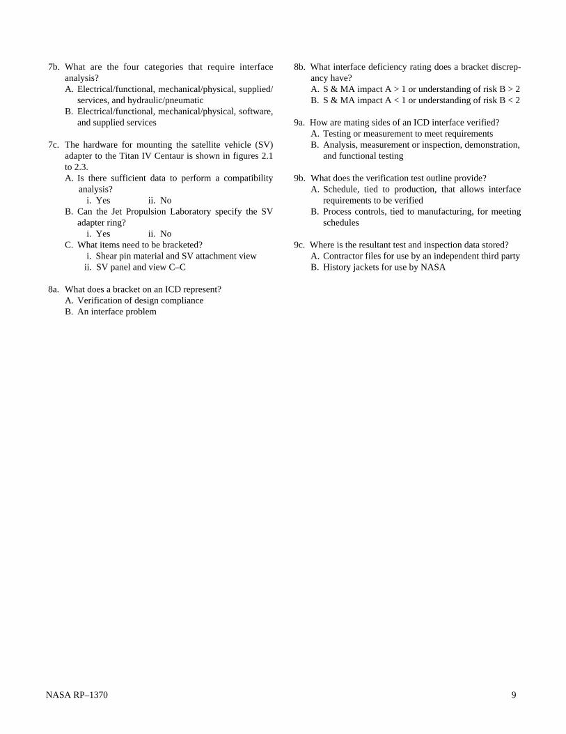
7c. The hardware for mounting the satellite vehicle (SV)adapter to the Titan IV Centaur is shown in figures 2.1to 2.3.A. Is there sufficient data to perform a compatibility
analysis?i. Yes ii. No
B. Can the Jet Propulsion Laboratory specify the SV adapter ring?
i. Yes ii. NoC. What items need to be bracketed?
i. Shear pin material and SV attachment view ii. SV panel and view C–C
8a. What does a bracket on an ICD represent?A. Verification of design complianceB. An interface problem
8b. What interface deficiency rating does a bracket discrep-ancy have?A. S & MA impact A > 1 or understanding of risk B > 2B. S & MA impact A < 1 or understanding of risk B < 2
9a. How are mating sides of an ICD interface verified?A. Testing or measurement to meet requirementsB. Analysis, measurement or inspection, demonstration,
and functional testing
9b. What does the verification test outline provide?A. Schedule, tied to production, that allows interface
requirements to be verifiedB. Process controls, tied to manufacturing, for meeting
schedules
9c. Where is the resultant test and inspection data stored?A. Contractor files for use by an independent third partyB. History jackets for use by NASA

10 NASA RP–1370
Fig
ure
2.1.
—T
itan
IV a
nd s
atel
lite
vehi
cle
phy
sica
l/en
velo
pe
inte
rfac
es.

NASA RP–1370 11
Fig
ure
2.2.
—T
itan
IV a
nd s
atel
lite
vehi
cle
ori
enta
tion.

12 NASA RP–1370
Fig
ure
2.3.
—T
itan
IV a
nd s
atel
lite
vehi
cle
adap
ter
ring
.

NASA RP–1370 13
Interface control should be started when a program begins.This process eventually will define all interface design anddocumentation responsibilities throughout the life cycle of theprogram. Each program phase from concept development toproject construction is directly related to the maturity level ofinterface control.
3.1 Program Phases
3.1.1 Concept Definition
During the system engineering concept definition phase(from fig. 1.1), basic functional areas of responsibility areassigned for the various pieces of equipment that will beemployed by the project (electrical power, environment con-trol, propulsion, etc.); see figure 3.1. At this point the designresponsibilities of the responsible organization and relatedcontractor (if chosen) should be defined to establish a set oftiered, traceable requirements. From these requirements theinterfaces to be designed are identified by category (electrical/functional, mechanical/physical, software, and supplied ser-vices) and by type of data that must be defined. This categori-zation will include a detailed review of each requirement todetermine which requirements or features will be controlled bythe interface control process. (What is important for this item tofulfill its intended function? On what interfacing equipment isthis function dependent?) Once the interfaces to be controlledare selected, the formal procedures for interface control need tobe established. These procedures include identifying the par-
Chapter 3
The Process: Through the Design Phasesticipants responsible for the interface control documentation,the approval or signoff loop for documentation, and the degreeto which all participants have to adhere to interface controlparameters and establishing a missing design data matrix,change procedures, etc. (See section 3.2.)
Early development of the interface process, products, andparticipants provides a firm foundation for the design engineerto use the correct information in designing his or her portion ofan interface. It minimizes the amount of paper to be reviewed,shortens the schedule, and concentrates the efforts of thedesigner on his or her area of responsibility.
Initial selection of interfaces generally begins with listing ofall pieces of equipment in a system and then identifying theextent of interrelation among them. One tool used to help in thisprocess is the N-squared diagram. Details of this process can befound in reference 4. The N-squared diagram was initially usedfor software data interfacing; however, some centers are usingit for hardware interfaces. If the diagram is not polarizedinitially (input/output characteristics not labeled), it is a conve-nient format for identifying equipment interfaces and for cat-egorizing them. An example of this form is shown in figure 3.2.This diagram can be further stratified to identify the interfacesfor each of the categories; however, detailed stratification isbest applied to electrical/functional, software, and suppliedservices interfaces. Using the N-squared diagram permits anorderly identification and categorization of interfaces that canbe easily shown graphically and managed by computer.
By the end of this phase the basic responsibilities andmanagement scheme, the framework for the interface controldocumentation, and the process for tracking missing interfacedesign data (see section 3.2.2) should be established anddisseminated.
3.1.2 Requirements Definition
During the requirements definition phase (fig. 3.3; fromfig. 1.1), the definitions of the mission objectives are completedso that each subsystem design can progress to development.Here, the technology to be used in the project will be defined tolimit the risk associated with the use of new, potentiallyunproven technologies. Defining requirements and baselininginterface documents early in the design process provides infor-mation to the designer needed to ensure that interface designis done correctly the first time. Such proactive attention tointerfaces will decrease review time, reduce unnecessarypaperwork, and shorten schedule times. By the end of require-ments definition all interface control documents should beprepared, interfaces defined to the most detailed extent pos-sible, and ICD’s presented for baselining.
• Assign basic functional areas of responsibility.
• Define design responsibilities.
• Categorize interfaces.
• Define interfaces to be controlled.
• Establish formal interface control procedures.
• Disseminate scheme, framework, traceability.
Figure 3.1.—Establishment of interface control process during concept definition.
Concept definition

14 NASA RP–1370
Structure
Fuel pods
Thrusters
Solar arrays
Heat converters
Voltage converters
Antenna A
Antenna BExperiment
1Experiment
2Experiment
3
Gyros
M M
M
E
E
E
E
E
E
M M M M M M
M
MM
M SS
M,E SS
M,E SS
M,E SS
E SS
M SS
M SSM,E
M,E
M,E
M,E
E M SS
Electrical/functional Mechanical/physical Supplied services
Key
Figure 3.2.—N-squared diagram for orbital equipment. (Entries not polarized.)
Baselining is the act by which the program manager ordesignated authority signs an ICD. That signature establishesthe ICD as an official document defining interface designrequirements. The term “baselining” is used to convey that theICD is the only official definition and that this officiality comesfrom the technical management level. Not only is the initialversion of the ICD baselined, but each subsequent change orupdate to an ICD is also baselined.
The baselined version of the ICD will identify (by a “void”)any missing design data that cannot be included at that time.Agreed-to due dates will be noted on the ICD for each dataelement required. Each void will define the data required andspecify when and by whom such data will be supplied. Wherepossible, the data to be supplied should be bounded initially onthe ICD. These bounds will be replaced by detailed data whenthe void is filled. The initial bounds give the data user (the otherside of the interface) a range that can be used without risk, untilthe detailed data are supplied. Establishing these voids onICD’s provides a means of ensuring that interface design dataare supplied when they are required by the data user. Yet itallows design freedom to the data supplier until the data areneeded. A recommended form for use in identifying the dataneeded is shown in figure 3.4. The criteria for choosing duedates are discussed in section 3.2.
• Define technologies to be used.
• Define and categorize all interfaces.
• Prepare all interface control documents.
• Identify all voids and assign both
responsibilities and due dates.
• Bound voids when possible.
• Baseline interface documents.
Figure 3.3.—Development and control of interfaces during requirements definition.
Requirementsdefinition
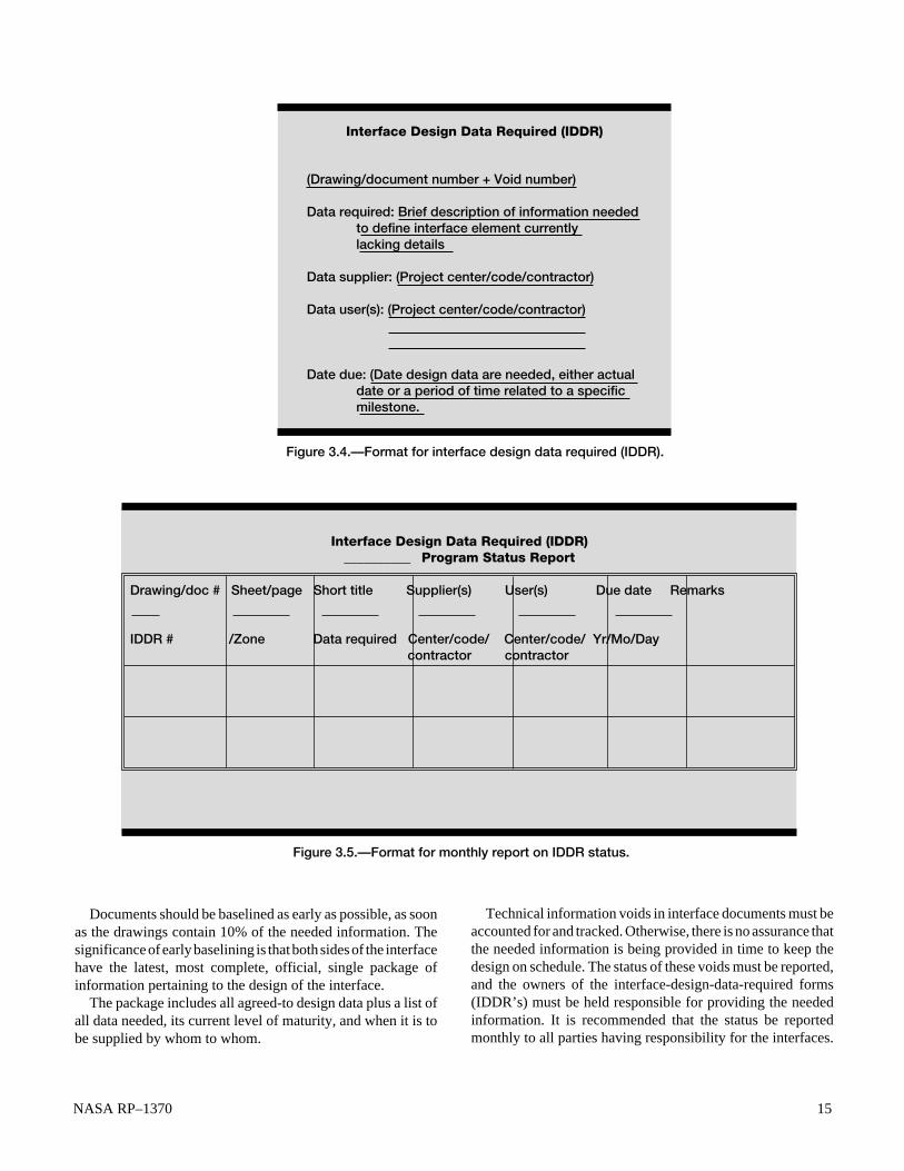
NASA RP–1370 15
(Drawing/document number + Void number) Data required: Brief description of information needed to define interface element currently lacking details Data supplier: (Project center/code/contractor) Data user(s): (Project center/code/contractor) Date due: (Date design data are needed, either actual date or a period of time related to a specific milestone.
Interface Design Data Required (IDDR)
Figure 3.4.—Format for interface design data required (IDDR).
Documents should be baselined as early as possible, as soonas the drawings contain 10% of the needed information. Thesignificance of early baselining is that both sides of the interfacehave the latest, most complete, official, single package ofinformation pertaining to the design of the interface.
The package includes all agreed-to design data plus a list ofall data needed, its current level of maturity, and when it is tobe supplied by whom to whom.
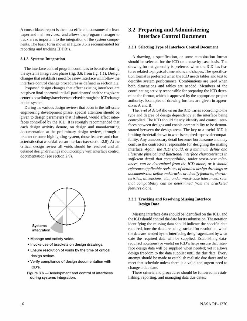
Technical information voids in interface documents must beaccounted for and tracked. Otherwise, there is no assurance thatthe needed information is being provided in time to keep thedesign on schedule. The status of these voids must be reported,and the owners of the interface-design-data-required forms(IDDR’s) must be held responsible for providing the neededinformation. It is recommended that the status be reportedmonthly to all parties having responsibility for the interfaces.
Figure 3.5.—Format for monthly report on IDDR status.
Drawing/doc # Sheet/page Short title Supplier(s) User(s) Due date Remarks IDDR # /Zone Data required Center/code/ Center/code/ Yr/Mo/Day contractor contractor
Interface Design Data Required (IDDR) __________ Program Status Report
16 NASA RP–1370
A consolidated report is the most efficient, consumes the leastpaper and mail services, and allows the program manager totrack areas important to the integration of the system compo-nents. The basic form shown in figure 3.5 is recommended forreporting and tracking IDDR’s.
3.1.3 Systems Integration
The interface control program continues to be active duringthe systems integration phase (fig. 3.6; from fig. 1.1). Designchanges that establish a need for a new interface will follow theinterface control change procedures as defined in section 3.2.
Proposed design changes that affect existing interfaces arenot given final approval until all participants’ and the cognizantcenter’s baselinings have been received through the ICD changenotice system.
During the various design reviews that occur in the full-scaleengineering development phase, special attention should begiven to design parameters that if altered, would affect inter-faces controlled by the ICD. It is strongly recommended thateach design activity denote, on design and manufacturingdocumentation at the preliminary design review, through abracket or some highlighting system, those features and char-acteristics that would affect an interface (see section 2.8). At thecritical design review all voids should be resolved and alldetailed design drawings should comply with interface controldocumentation (see section 2.9).
3.2 Preparing and AdministeringInterface Control Document
3.2.1 Selecting Type of Interface Control Document
A drawing, a specification, or some combination formatshould be selected for the ICD on a case-by-case basis. Thedrawing format generally is preferred when the ICD has fea-tures related to physical dimensions and shapes. The specifica-tion format is preferred when the ICD needs tables and text todescribe system performance. Combinations are used whenboth dimensions and tables are needed. Members of thecoordinating activity responsible for preparing the ICD deter-mine the format, which is approved by the appropriate projectauthority. Examples of drawing formats are given in appen-dixes A and B.
The level of detail shown on the ICD varies according to thetype and degree of design dependency at the interface beingcontrolled. The ICD should clearly identify and control inter-faces between designs and enable compatibility to be demon-strated between the design areas. The key to a useful ICD islimiting the detail shown to what is required to provide compat-ibility. Any unnecessary detail becomes burdensome and mayconfuse the contractors responsible for designing the matinginterface. Again, the ICD should, at a minimum define andillustrate physical and functional interface characteristics insufficient detail that compatibility, under worst-case toler-ances, can be determined from the ICD alone; or it shouldreference applicable revisions of detailed design drawings ordocuments that define and bracket or identify features, charac-teristics, dimensions, etc., under worst-case tolerances, suchthat compatibility can be determined from the bracketedfeatures alone.
3.2.2 Tracking and Resolving Missing Interface Design Data
Missing interface data should be identified on the ICD, andthe ICD should control the date for its submission. The notationidentifying the missing data should indicate the specific datarequired, how the data are being tracked for resolution, whenthe data are needed by the interfacing design agent, and by whatdate the required data will be supplied. Establishing data-required notations (or voids) on ICD’s helps ensure that inter-face design data will be supplied when needed; yet it allowsdesign freedom to the data supplier until the due date. Everyattempt should be made to establish realistic due dates and tomeet that schedule unless there is a valid and urgent need tochange a due date.
These criteria and procedures should be followed in estab-lishing, reporting, and managing data due dates:
• Manage and satisfy voids.
• Invoke use of brackets on design drawings.
• Ensure resolution of voids by the time of critical
design review.
• Verify compliance of design documentation with
ICD's.
Figure 3.6.—Development and control of interfaces during systems integration.
Systems integration

NASA RP–1370 17
1. Choose the due date as the date when the data user willstart to be affected if agreed-upon or baselined data have notbeen received.
2. When establishing a due date, allow time to process andauthenticate a change notice to the ICD (i.e., once the due datehas been established, include a period of time to establish thatdue date for the data supplier).
3. The custodian responsible for the ICD should periodi-cally, as determined by the appropriate project authority,prepare and distribute a report on the status of all missing designinformation for all project activities. The report should containthe following information:
a. Identification of the data element needed, consisting ofthe ICD number, the date, and a two- or three-digitnumber that provides a unique identifier for the dataelement
b. A short title for the ICDc. The activity that requires the datad. The date when the missing data are to be supplied or
the period of time after the completion of a programevent or milestone when the data are to be supplied
e. The activity from which the data are duef. The status of the data required (i.e., late data, data in
preparation, or change notice number)g. A description of the data required
3.3 Initial Issuance of ICD
The first issue of an ICD should be a comment issue. Thecomment issue is distributed to participating centers and con-tractors for review and comment as designated in the interfaceresponsibility matrix (fig. 3.7).
The interface custodian generates the responsibility matrixfor ICD’s. The matrix specifies the center and contractorresponsibilities for baselining, review and comment, and tech-nical approval. The matrix lists all ICD’s applicable to aparticular program. Distribution of the ICD’s can then becontrolled through this matrix as well.
The review and comment process is iterative and leads toagreement on system interface definitions and eventual approvaland baselining of the ICD. See figure 3.8 for a flow diagram ofthe issuance, review and comment, and baselining proceduresfor ICD’s. Concurrent distribution of the comment issue to allparticipants minimizes the time needed for review and subse-quent resolution of differences of opinion.
3.4 Document Review and Comment
As designated in the ICD responsibility matrix, all centersand contractors should submit technical comments through the
appropriate authority to all other activities with review andcomment responsibilities for the particular ICD and to the ICDcustodian.
Technical comments by all activities should be transmittedto the custodian as soon as possible but not later than 30working days4 from receipt of the comment issue. If thecomment issue is technically unacceptable to the Governmentauthority or the interfacing contractor, the rationale forunacceptability should be explained, including technical andcost effects if the interface definition is pursued as presented.
3.4.1 Resolving Comments
The ICD custodian collects review comments and works inconjunction with project management for comment resolutionuntil approval is attained, the comment is withdrawn, or theICD is cancelled. Information on comments and their disposi-tion and associated resolution should be documented andtransmitted to all participants after all comments have beenreceived and dispositioned. Allow two weeks4 for participantsto respond to the proposed resolution. Nonresponses can beconsidered concurrence with the resolutions if properprenotification is given to all participants and is made part of thereview and comment policy.
When comments on the initial comment issue require majorchanges and resolution is not achieved through informal com-munications, an additional comment issue may be requiredand/or interface control working group (ICWG) meetings mayneed to be arranged.
3.4.2 Interface Control Working Group
The ICWG is the forum for discussing interface issues.ICWG meetings serve two primary purposes: to ensure effec-tive, detailed definition of interfaces by all cognizant parties,and to expedite baselining of initial ICD’s and subsequentdrawing changes by encouraging resolution of interface issuesin prebaselining meetings. A major goal of interface controlshould be that baselining immediately follow a prebaseliningICWG meeting.
All ICWG meetings must be convened and chaired by thecognizant project organization. The project can choose a con-tractor to act as the chair of an ICWG when Governmentcommitments are not required. In all cases the ICWG membersmust be empowered to commit the Government or contractor tospecific interface actions and/or agreements. In cases where acontractor is ICWG chair, the contractor must report to theGovernment any interface problems or issues that surfaceduring an ICWG meeting.
4The times assigned for commenting activities to respond are arbitrary andshould be assigned on the basis of the schedule needs of the individualprograms.

18 NASA RP–1370
(1)
Maj
or
pro
ject
ap
plic
abili
tyN
AS
A d
ata
inte
rfac
e lis
t P
rog
ram
__
(2) _
____
_
(3) I
nter
face
ca
teg
ory
:
(9)
(6)
(6)
(6)
(6)
(6)
(6)
(6)
(6)
(6)
(6)
(7)
(7)
(7)
(8)
(5)
(5)
(5)
(5)
(5)
(4) R
evie
w, c
om
men
t, in
form
atio
n re
spo
nsib
ilitie
sT
echn
ical
ap
pro
val
auth
ori
ty
AU
No
tes
Key
: (1
) Maj
or
pro
ject
/pro
gra
m a
pp
licab
ility
(e.g
., N
ST
S).
(2) P
rim
ary
pro
ject
/pro
gra
m o
wne
rshi
p o
f in
terf
aces
. (3
) Cat
ego
ry o
f in
terf
ace
cove
red
by
list
(e.g
., el
ectr
ical
/fun
ctio
nal).
(4
) Rev
iew
, co
mm
ent,
and
info
rmat
ion
(RC
&I)
resp
ons
ibili
ties
by
NA
SA
cen
ter
(list
ed in
(5)).
(5
) Cen
ter
resp
ons
ible
fo
r R
C&
I of
the
inte
rfac
e d
ocu
men
t.
(6) C
ente
r co
de
or
cont
ract
or
do
ing
RC
&I.
(7) C
ente
r ha
ving
tec
hnic
al a
pp
rova
l sig
natu
re a
utho
rity
(one
co
lum
n fo
r ea
ch a
pp
licab
le c
ente
r).
(8) N
AS
A o
rgan
izat
ion
havi
ng a
uthe
ntic
atio
n re
spo
nsib
ility
(sin
gle
org
aniz
atio
n fo
r au
then
ticat
ion
of
a b
asel
ined
do
cum
ent
follo
win
g t
echn
ical
ap
pro
val
b
y th
e o
rgan
izat
ions
in c
olu
mns
mar
ked
by
(7)).
(9
) Dra
win
g/d
ocu
men
t nu
mb
er a
nd s
hort
titl
e.
Fig
ure
3.7.
—In
terf
ace
resp
ons
ibili
ty m
atri
x.

NASA RP–1370 19
ICD custodian develops comment issue of ICD
Issuance Issuance
Contractors review and comment
Centers review and comment
Comments
Resolution cycle
Resolution cycle
ICD custodian coordinates and resolves comments* * Interface control
working group meetings are scheduled as needed.
Technical approval by NASA centers and contractors
Distribution of ICD to all participants
Monthly status reports
Figure 3.8.—Flow of interface control document production.
The ICWG chair prepares the ICWG meeting minutes ordesignates one of the meeting participants for this task. Theminutes should include discussions of problems, agreementsreached, decisions made, and action items. The ICWG chairalso ensures that any updated interface control documentationreflecting the ICWG discussions is distributed within thetimeframe agreed to by the affected participants.
3.4.3 Approval/Signoff Cycle
The management plan for the project assigns responsibilityfor each piece of equipment to a specific project authority andits contractor. The signoff loop for each ICD reflects this planand can be related to the project and the origin of each designrequirement. For each ICD, then, the signoff loop follows thesequence of technical approval by the contractors first and thenby the appropriate project authority.
3.4.4 Technical Approval
The appropriate project authority and the primary and asso-ciate organizations with an interest in a particular ICD are listedin the responsibility matrix. They each sign the ICD to signifytechnical agreement and a readiness to contractually invoke itsrequirements.
3.4.5 Baselining
Interface control documents are baselined when the ownersof both sides of the interface at the next level up in the programstructure come to technical agreement and sign the document.
3.5 Change Notices
The procedure for initiation, review, technical approval,baselining, and distribution of changes to project ICD’s(fig. 3.9) should conform to the following guidelines.
3.5.1 Initiating Changes
Any project activity should request a change to an ICD when
1. Data are available to fill a void.2. Information contained in a data-required note needs to be
modified.3. Additional data are needed (i.e., a new data requirement
has been established).4. A technical error is discovered on the ICD.

20 NASA RP–1370
Originate change request (any participant)
Issuance Issuance
Contractors review and comment
Project reviews and comments
CommentsResolution cycle
Resolution cycle
ICD custodian coordinates and resolves comments
Technical approval by NASA project and contractors
Authentication by NASA
Direction to proceed as required to contractor
* Distribution of change notice
Change master ICD to incorporate change and distribute
Incorporate change into project
ICD custodian reviews and prepares proposed change notice
Contractors (for information)
Project (for information)
ICWG meeting as required
* Distribution per ICD distribution matrix
Figure 3.9.—Development and flow of change notices in the ICD revision process.

NASA RP–1370 21
5. An equipment design change and a system or equipmentrearrangement are proposed to improve performance,reduce cost, or expedite scheduled deliveries that would requirechanges to an interface or creation of new interfaces.
3.5.2 Requesting Changes
All requests for changes should be submitted to the organi-zation responsible for maintaining the ICD, with copies to allactivities that will review the resultant change notices and to theappropriate project authority. If baselining is needed in lessthan 30 days, a critical change should be requested. All requestsfor changes should be submitted in a standard format thatincludes the following items:
1. Originator’s identification number—It is used as a refer-ence in communications regarding the request and shouldappear on resulting change notices
2. Originating activity—originating project and code ororiginating contractor
3. Point of contact—name, area code, telephone number,facsimile number, and e-mail address of the person at theoriginating activity to be contacted regarding the request
4. Document affected—number, revision letter, and shorttitle of each ICD that would be affected by the change
5. Number of data voids (if applicable)—number of datarequirements for which data are being provided
6. Urgency—indication of whether this change is critical orroutine (project decides whether to use critical route)
7. Detailed description of change—a graphic or textualdescription of the change in sufficient detail to permit a clearportrayal and evaluation of the request. Separate descriptionsshould be provided when more than one ICD is affected.
8. Justification—concise, comprehensive description of theneed and benefit from the change
9. Impact—concise, comprehensive description of the ef-fect in terms of required redesign, testing, approximate cost,and schedule effects if the requested change is not approved;also the latest date on which approval can occur and not affectcost or schedule10. Authorizing signature of the organization requiring the
change
Upon receipt of a change request to an ICD, the ICDcustodian coordinates the issuance of a proposed change notice.First, the ICD custodian evaluates the technical effect of theproposed change on the operation of the system and matingsubsystem. If the effect of the change is justified, the ICDcustodian generates and issues a change notice. If the justifica-tion does not reflect the significance of the change, the ICDcustodian rejects the request, giving the reason or asking forfurther justification from the originating organization. The ICDcustodian evaluates an acceptable change request to determinewhether it provides data adequate to generate a change notice.
The proposed change notice describes the specific changes(technical or otherwise) to the ICD in detail by “from-to”delineations and the reasons for the changes, as well as whorequested the changes and how the change request was trans-mitted (i.e., by letter, facsimile, ICWG action item, etc.).
3.5.3 Proposed Change Notice Review and Comment Cycle
The review and comment cycle for proposed changes toICD’s should follow the same system as that used for the initialissuance of the ICD (see sections 3.3 and 3.4).
3.5.4 Processing Approved Changes
The baselined change notice should be distributed to allcognizant contractors and project parties expeditiously to prom-ulgate the revised interface definition. The master ICD isrevised in accordance with the change notice, and copies of therevised sheets of the ICD are distributed (see sections 3.3 and3.4). Approval of the change by the project constitutes author-ity for the cognizant organization to implement the relatedchanges on the detailed design.
3.5.5 Distributing Approved Changes
The custodian distributes the baselined change notice to allcognizant centers and contractors to expeditiously promulgatethe revised interface definition. The master ICD is then revisedin accordance with the change notice, and copies of the revisedICD sheets are distributed as was the change notice.The responsibility matrix (fig. 3.7) can be used to identify thedistribution of change notices as it was used for the distributionof the ICD’s.
3.5.6 Configuration Control Board
During development the project’s configuration controlboard is responsible for reviewing and issuing changes to theconfiguration baseline. The board reviews all class I engineer-ing change proposals to determine if a change is needed and toevaluate the total effect of the change. The configurationcontrol board typically consists of a representative from thechairman, the project management office, customers, engineer-ing, safety assurance, configuration management (secretary),fabrication, and others as required.
Changes to configuration items can only be effected by theduly constituted configuration control board. The board firstdefines a baseline comprising the specifications that governdevelopment of the configuration item design. Proposed changesto this design are classified as either class I or class II changes.Class I changes affect form, fit, or function. However, otherfactors, such as cost or schedule, can cause a class I change.Class I changes must be approved by the project before beingimplemented by the contractor.

22 NASA RP–1370
All other changes are class II changes. Examples of class IIchanges are editorial changes in documentation or hardwarechanges (such as material substitution) that do not qualify asclass I changes. Project concurrence, generally, is required forthe contractor to implement class II changes. Government plantrepresentatives (Defense Contracts Administration Services(DCAS), Navy Programs Resident Office (NAVPRO), and AirForce Programs Resident Office (AFPRO) usually accomplishthese tasks.
3.5.7 Closing the Loop
A wide range of methods are available for verifying by testthat the design meets the technical requirements. During thedefinition phase analysis may be the only way of assessing whatis largely a paper design. Typical methods are testing bysimilarity, analysis, modeling, and use of flight-proven compo-nents; forecasting; and comparison, mathematical modeling,simulation modeling, and using flight-proven experience anddecisions. The actual methods to be used are determined by theproject office. Each method has associated costs, requiresdevelopment time, and provides a specific level of performanceverification. The Government and industry managers mustcarefully trade off program needs for performance verificationwith the related costs.
If any demonstrated or forecast parameter falls outside theplanned tolerance band, corrective action plans are prepared bythe contractor and reviewed by the Government project office.Each deviation is analyzed to determine its cause and to assessthe effect on higher level parameters, interface requirements,and system cost effectiveness. Alternative recovery plans aredeveloped showing fully explored cost, schedule, and technicalperformance implications. Where performance exceeds re-quirements, opportunities for reallocation of requirements andresources are assessed.
Although functional and performance requirements are con-tained in the appropriate configuration item specification, thedefinition, control, and verification of interface compatibilitymust be handled separately. Otherwise, the volume of detailwill overwhelm both the designers and managers responsiblefor meeting the functional and performance requirements of thesystem. Early establishment of the interface definition andcontrol process will provide extensive savings in schedule,manpower, money, and paper. This process will convey pre-cise, timely information to the interface designers as to what thedesigner of the opposing side is committed to provide or needsand will subsequently identify the requirements for verifyingcompliance.
Whether the interface is defined in a drawing format or in anarrative format is at the discretion of the program. What is ofprimary importance is that only the information necessary todefine and control the interface should be on these contracturaldocuments to focus the technical users and minimize the needfor updating information.
Appendix G provides seven ICD guidelines that have beenused by many successful flight projects and programs to pro-vide such a focus on the interface definition and controlprocess.
3.6 Training2
1a. When should the ICD process be started?A. Concept definition B. Requirements definitionC. Systems integration
1b. What are the benefits of early development of the ICDprocess?A. Assigns basic areas of responsibilityB. Provides firm foundation for design, minimizes
paper, shortens schedule, and concentrates efforts
1c. What tool can be used to list equipment and identify theirinterrelations in a system?A. Prechart B.N-squared diagram
2a. What should be done in the ICD process during require- ments definition?
A. Define mission objectivesB. Define technology and interfaces and present for
baselining
2b. What is baselining?A. The designated authority signing an ICDB. The only official definition
2c. How are voids in an ICD accounted for and tracked?A. Procedure or administration reportB. Monthly program status report on interface design
data required
3a. What should be done in the ICD process during develop-ment?A. Manage voids, invoke brackets, resolve voids, and
verify complianceB. Control interface developments
3b. How should proposed design changes be handled?A. Discussed at critical design reviewB. Discussed and approved by all participants
3c. What should be given special attention?A. Design parameters that affect controlled ICDB. Manufacturing documentation
2Answers are given at the end of this manual.

NASA RP–1370 23
4a. When is the drawing format used for an ICD?A. To describe the type and nature of the componentB. To describe physical dimensions and shapes
4b. When should a specification be used?A. To describe performance with tables and textB. To describe a software function
4c. What is the key to providing a useful ICD?A. Give as much detail as possibleB. Limit the detail to what is necessary to demonstrate
compatibility
5a. What is the purpose of the initial issue of an ICD?A. Issuance, review, comment, and baseliningB. Review and resolution of differences of opinion
5b. Who is responsible for controlling the flow of an ICD?A. ContractorB. Custodian
6a. Who should review ICD’s?A. Organizations designated in the responsibility
matrixB. ICD custodian
6b. How are comments resolved?A. By the project officeB. By project management and custodian working for
resolution and approval or the comment being with-drawn
6c. Where are interface issues discussed?A. Project officeB. Interface control working group
6d. Who approves and baselines an ICD?A. Projects at the next level up in program structureB. The project office
7a. When should a project activity request a change to an ICD?A. At the custodian’s requestB. When data are available, requirements need change,
an error is discovered, or the design changes
7b. What items should be included in a change notice request?A. Identification number, activity, contact, document
affected, number of data voids, urgency, descrip-tion, justification, impact, and authorizing signature
B. Those established by the ICWG
7c. Who evaluates and issues a proposed change notice?A. ICD custodianB. Project office
7d. What does a proposed change notice describe?A. Specific changes (from-to), reasons, and the
requestorB. Project notices
7e. How is a change notice approved and distributed?A. By the project authority to all cognizant partiesB. By all cognizant parties to the contractors
National Aeronautics and Space AdministrationLewis Research CenterCleveland, Ohio, 44135, July 1995.

24 NASA RP–1370
Appendix A
Electrical/Functional Interface ExampleThis appendix illustrates elements of a telemetry drawing
interface control document showing control of waveformparameters and data rates. This interface example depicts datatransfer between a guidance system electronics assembly and alaunch vehicle telemetry system. The basic drawing (fig. A.1)covers the isolation elements of the guidance system, the jackand pins assigned, and shielding and grounding on the guidanceside of the interface. Bus functions are named (e.g., guidancetelemetry data 1(parametric)), and the shielding requirementsthrough to the first isolating elements of the telemetry systemare provided (see notes on fig. A.1).
Table A.1 contains the details to be controlled for each busfunction. Signal source (electronics assembly) and destination(telemetry system) are identified. The waveform (fig. A.2) andits critical characteristics (table A.2) are provided, as well asdata rates and sources and load impedances. Telemetry loadimpedance is further described by an equivalent circuit (seenote 3 on fig. A.1).
The final value of pulse minimum amplitude is missing inthis example. This is noted by the design-data-required (DDR)
callout in table A.2 and the accompanying DDR block (fig.A.3). The DDR block notes that the responsible parties haveagreed on an amplitude band with which they can work until theguidance design becomes firm. However, there is also a datecalled out that indicates when (45 days after preliminary designreview) the telemetry contractor must have the data to be ableto complete design and development and deliver the telemetryin time to support launch vehicle flight.
The parameters called out in this example are only thoseneeded to control the design of either side of the interfacethrough the first isolating element. Also note that only theshielding and wire gage of the launch vehicle cabling betweenthe two systems are provided. Only pin numbers for theguidance side of the interface are called out and controlled.Connector types and other pertinent cable specifications are asper a referenced standard that applies to all launch vehiclecabling. In this case the same pulse characteristics apply to eachof the functions covered; however, table A.2 is structured topermit variation for each function if the design should dictatedifferent values for the characteristics of each function.
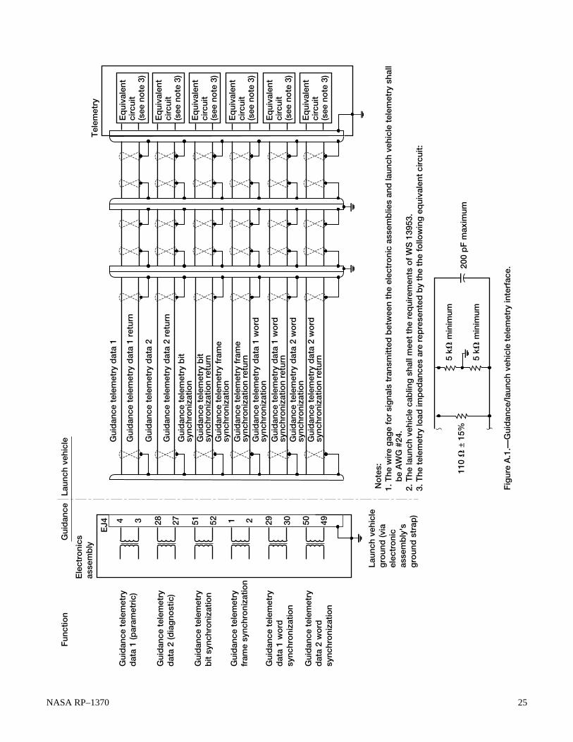
NASA RP–1370 25
Gui
dan
ce t
elem
etry
d
ata
1 (p
aram
etri
c)
Gui
dan
ce t
elem
etry
d
ata
2 (d
iag
nost
ic)
Gui
dan
ce t
elem
etry
b
it sy
nchr
oni
zatio
n
Gui
dan
ce t
elem
etry
fr
ame
sync
hro
niza
tion
Gui
dan
ce t
elem
etry
d
ata
1 w
ord
sy
nchr
oni
zatio
n
Gui
dan
ce t
elem
etry
d
ata
2 w
ord
sy
nchr
oni
zatio
n
4 3 28 27 51 52 1 2 29 30 50 49
Laun
ch v
ehic
le
gro
und
(via
el
ectr
oni
c as
sem
bly
's
gro
und
str
ap)
EJ4
Ele
ctro
nics
as
sem
bly
Fun
ctio
nG
uid
ance
La
unch
veh
icle G
uid
ance
tel
emet
ry d
ata
1
Gui
dan
ce t
elem
etry
dat
a 1
retu
rn
Gui
dan
ce t
elem
etry
dat
a 2
retu
rn
Gui
dan
ce t
elem
etry
bit
sync
hro
niza
tion
Gui
dan
ce t
elem
etry
fra
me
sync
hro
niza
tion
Gui
dan
ce t
elem
etry
fra
me
sync
hro
niza
tion
retu
rnG
uid
ance
tel
emet
ry d
ata
1 w
ord
sy
nchr
oni
zatio
nG
uid
ance
tel
emet
ry d
ata
1 w
ord
sy
nchr
oni
zatio
n re
turn
Gui
dan
ce t
elem
etry
dat
a 2
wo
rd
sync
hro
niza
tion
Gui
dan
ce t
elem
etry
dat
a 2
wo
rd
sync
hro
niza
tion
retu
rn
Gui
dan
ce t
elem
etry
dat
a 2
Gui
dan
ce t
elem
etry
bit
sync
hro
niza
tion
retu
rn
Eq
uiva
lent
ci
rcui
t (s
ee n
ote
3)
Eq
uiva
lent
ci
rcui
t (s
ee n
ote
3)
Eq
uiva
lent
ci
rcui
t (s
ee n
ote
3)
Eq
uiva
lent
ci
rcui
t (s
ee n
ote
3)
Eq
uiva
lent
ci
rcui
t (s
ee n
ote
3)
Eq
uiva
lent
ci
rcui
t (s
ee n
ote
3)
Tel
emet
ry
Fig
ure
A.1
.—G
uid
ance
/lau
nch
vehi
cle
tele
met
ry in
terf
ace.
No
tes:
1.
The
wir
e g
age
for
sig
nals
tra
nsm
itted
bet
wee
n th
e el
ectr
oni
c as
sem
blie
s an
d la
unch
veh
icle
tel
emet
ry s
hall
b
e A
WG
#24
. 2.
The
laun
ch v
ehic
le c
ablin
g s
hall
mee
t th
e re
qui
rem
ents
of
WS
139
53.
3. T
he t
elem
etry
load
imp
edan
ces
are
rep
rese
nted
by
the
the
follo
win
g e
qui
vale
nt c
ircu
it:
5
kV m
inim
um
5 kV
min
imum
110
V ±
15%
200
pF
max
imum
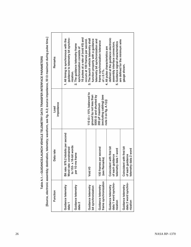
26 NASA RP–1370
Fun
ctio
nD
ata
rate
Load
im
ped
ance
Rem
arks
Bit
rate
: 979
.2 k
ilob
its p
er s
eco
nd
Wo
rd r
ate:
co
nstr
aine
d
to
153
- x
16-b
it w
ord
s
p
er 1
0-m
s fr
ame
Vo
id #
3 10
0 fr
ames
per
sec
ond
(s
ee R
emar
ks)
Co
inci
den
t w
ith f
irst
bit
of
each
gui
dan
ce
tele
met
ry d
ata
1 w
ord
C
oin
cid
ent
with
fir
st b
it o
f ea
ch g
uid
ance
te
lem
etry
dat
a 2
wo
rd
110
V ±
15%
bal
ance
d t
o
gro
und
by
not
less
tha
n 50
00 V
and
shu
nted
by
200
pF
max
imum
(e
xclu
din
g c
ablin
g) (
see
note
3 o
n fig
. A.1
(c))
1. A
ll tim
ing
is s
ynch
rono
us w
ith t
he
g
uid
ance
to
tel
emet
ry b
it sy
nchr
o-
n
izat
ion.
2.
The
gui
dan
ce t
elem
etry
fra
me
s
ynch
roni
zatio
n co
nsis
ts o
f
16
pul
ses
at a
rat
e o
f (v
oid
#3)
and
occ
urs
at 1
00 f
ram
es p
er s
eco
nd.
3. T
he la
unch
veh
icle
tel
emet
ry s
hall
f
unct
ion
pro
per
ly w
ith a
gui
dan
ce
t
elem
etry
bit
sync
hro
niza
tion
and
fra
me
sync
hro
niza
tion
tole
ranc
e
of
± 0.
1%.
4. A
ll p
ulse
cha
ract
eris
tics
are
d
efin
ed a
t th
e g
uid
ance
ele
ctro
nic
a
ssem
bly
inte
rfac
e co
nnec
tors
. 5.
Gui
dan
ce s
igna
l cha
ract
eris
tics
a
re d
efin
ed f
or
the
min
imum
wir
e
gau
ge
sho
wn.
Gui
dan
ce t
elem
etry
d
ata
1 G
uid
ance
tel
emet
ry
dat
a 2
Gui
dan
ce t
elem
etry
b
it sy
nchr
oni
zatio
n G
uid
ance
tel
emet
ry
fram
e sy
nchr
oni
zatio
n G
uid
ance
tel
emet
ry
dat
a 1
wo
rd s
ynch
ro-
niza
tion
Gui
dan
ce t
elem
etry
d
ata
2 w
ord
syn
chro
- ni
zatio
n
Tab
le A
.1.—
GU
IDA
NC
E/L
AU
NC
H V
EH
ICLE
TE
LEM
ET
RY
DA
TA
TR
AN
SF
ER
INT
ER
FA
CE
PA
RA
ME
TE
RS
[So
urce
, ele
ctro
nic
asse
mb
ly; d
estin
atio
n, t
elem
etry
; wav
efo
rm, s
ee f
ig. A
.2; s
our
ce im
ped
ance
, 50
V m
axim
um d
urin
g p
ulse
tim
e.]

NASA RP–1370 27
Leading edge
Trailing edge
Interpulse period Interpulse period
Reference level
Noise
Rise time
Fall time
Undershoot
No-transmission level
Offset
Pulse duration
10% of minimum amplitudeMinimum amplitude
Maximum amplitude
Figure A.2.—Guidance data pulse characteristics.
Notes: 1. The interpulse period shall be the period from 150 ns after the trailing edge of a pulse until 100 ns prior to the leading edge of the subsequent pulse. 2. The reference level shall be the average voltage for the last 200 ns of the interpulse period. 3. The no-transmission level shall be 0 V differential at the guidance/launch vehicle interface using the test load specified in table A.2. 4. Shielding depicted represents the telemetry shielding requirements only. For cable routing see void #01. Telemetry shielding shall be carried through all connectors between the electronic assembly and the telemetry subsystem. 5. A radiofrequency cap shall be provided on electronic assemblies in all launch vehicles in lieu of this connector.

28 NASA RP–1370
Pulse characteristics
(see fig. A.2) Data 1 Data 2 Bit synchronization
Frame synchronization
Data 1 word synchronization
Data 2 word synchronization
Pulse duration Minimum amplitude Maximum amplitude Rise time Fall time Undershoot Reference level offset Noise Receiver susceptibility Test parameters:a
Test load Receiver susceptibility
255 + 50 ns 9 ± 2 V (see V027) 15 V 75 ns maximum 125 ns maximum 2.5 V maximum 0 to –4.5 V relative to no-transmission level 1.4 V maximum peak to peak 2.0 V minimum 75 V±5% resistive 2.0 V minimum
Guidance telemetry
Table A.2.—REQUIRED PULSE CHARACTERISTICS AND TEST PARAMETERS
Figure A.3.—Typical design data required for table A.2.
DDR No. 3288399–V027 Data required: Data supplier: Data user(s): Date due:
Guidance subsystem waveform parameter data (minimum amplitude value to replace coordinated temporary amplitude band currently on ICD–3288399) SP–2012/guidance telemetry steering committee SP–2732/launch vehicle telemetry contractor/interface coordinator 45 days following guidance preliminary design review

NASA RP–1370 29
one or the other. Considering the function of themounting bolts—to locate the box relative to theelectrical connectors, it has to be assumedthat dimensions a, b, c, and d are basic dimensions.Interface control drawings cannot require thedesigner of the mating interface to assume any-thing. IDD’s must stand by themselves.
b. Figure B.3 depicts initial details of mounting boltsfor the L-shaped bracket. On first inspection thereappears to be a great amount of detail. However, furtherexamination shows that much of the detail is not relatedto interface definition. The interface is the bolt. Whereis it relative to other features of the box? What is therelationship of bolts 1 and 2 to bolt 3 (datum C)?What is the thread of the bolt? How long is the bolt?The following data on the IDD are not required:
i. Counterbore for bolt headii. Diameter of bolt hole in bracket for bolts 1, 2,
and 3iii. Distance of bolt hole to first threadiv. The fact that there is a screw retaining ring
Adding data not required for the interface, even if theyare only pictorial, is expensive. It takes time for theorganization to develop and present it, and it takestime for the designer of the mating interface to deter-mine that the information is not necessary and discardit. If the extraneous information stays on the IDD, itmust be maintained (i.e., changed if the design detailschange). Only the features of a design that affect thefeatures of the design of the mating interfaces needbe placed on the IDD.
c. Once the unnecessary data are removed, what remainsis shown in figure B.4. The data that remain are notcomplete and are unclear. The true position notationsare indicated as being those for the “mounting inter-face for bolt,” suggesting that the true position appliesto the hole in the support structure. However, since theIDD is basically covering the features of the box, it isassumed that these locations apply to the bolts on thebox. It should not be necessary to have to makeassumptions about data on an IDD or ICD. Thedocument should stand by itself.
The only other data left in figure B.4 are the callouts forthe locking inserts. These callouts refer to the methodused by the designer of the support structure for retainingthe bolts. This IDD should not have this callout, since the
Appendix B
Mechanical/Physical Interface ExamplesB.1 Mechanical Interface for Distributed Electrical Box
Figure B.1 is an example of an interface development docu-ment (IDD) that, from initial inspection, appears to be fairlycomplete. This figure contains a great amount of detail and justabout everything appears to be dimensioned. However, closerexamination will reveal serious shortcomings.
First, the basic function of the interface must be defined. Thebox depicted must be capable of being removed and replaced onorbit, in many cases outside the crew habitat. In some cases itis to be removed and replaced robotically. The box slides alongthe L-shaped bracket held to the support structure by threemounting bolts labeled “bolt 1,” “ bolt 2,” and “bolt 3.” As thebox slides along the L-shaped bracket from left to right in thefigure, some piloting feature on the box connectors engages theconnectors mounted to the support structure by the spring-mounted assembly, and the connector engages fully when thelead screw is completely engaged.
1. The initial interface area to be examined is that of theL-shaped bracket to the support structure (i.e., the interface ofthe three mounting bolts). The interface is being examined fromthe perspective of the designer of the support structure. Doesfigure B.1 contain enough information for a mating interface tobe designed? (The area of interest has been enlarged and ispresented as figure B.2.)
a. The dimensions circled in figure B.2 and lettered a, b,c, and d locate the position of the mounting boltsrelative to the box data. The following pertinentdifferences are noted concerning this dimensioning:i. Dimension a locates the holes relative to a “refer-
ence datum for coldplate support structure,” butthe datum is not defined on the drawing. Is it a lineor a plane? What are the features that identify/locatethe datum? What is the relationship of this datum toother data identified on the IDD (data A, B, and D)?This information is required so that the designerof the support structure can relate his or herinterface features easily to those of the box IDD.
ii. The IDD states that the tolerances on three-placedecimals is ±0.010. Dimensions a, b, c, and dare three-place decimal dimensions and would,therefore, fall under this requirement. Elsewhere onthe IDD a true position tolerance for bolt locationsis indicated. A feature cannot be controlled by bothbilateral and true positioning tolerancing. It must be

30 NASA RP–1370
Fig
ure
B.1
.—P
artia
l int
erfa
ce d
evel
op
men
t d
ocu
men
t fo
r m
ultiu
se e
lect
rica
l po
wer
inte
rfac
e b
ox
sho
win
g b
olt
loca
tions
.

NASA RP–1370 31
Figure B.2.—Detail of L-shaped bracket interface.
d c b a
Figure B.3.—Initial details of mounting bolts.

32 NASA RP–1370
2. The next area to be examined is that of the connectorinterface. Since both parts of the connector are being providedby the box designer, the interface is the plate on which theconnectors are attached to the support structure. Again, thequestion is, Does figure B.1 contain enough information for amating interface to be designed? The answer to that question is,Definitely not! The interface of the plate (holding the connec-tors) that mates with the support structure is identified as datumD. Again, there is no definition of this datum. Is it a planepassing through the three highest points of the plate or someother features of the connector plate?
If a compatible mating interface is to be designed, therelationship between the surface to which the connector plate isattached and the surface to which the L-shaped bracket isattached must be known. None of these data are supplied infigure B.1. The following are data needed to establish thisrelationship:
method used for retaining the bolts is not the responsibil-ity of the box designer. Generally IDD’s and ICD’sshould not specify design solutions, especially whenthe design solutions are not the responsibility of theone specifying them.
What is missing is how far the bolts protrude from thebox. These data are required so that the designer of thesupport structure knows how deep to make the matinghole and how much of a mating thread must be suppliedto grip the bolts on the box.
Considering all of the above, figure B.5 representswhat is really required (along with the locations andthread types already defined in fig. B.1) to define the boxside of the interface and for the designers of the supportstructure to design a compatible interface between theretaining bolts and the support structure.
Figure B.5.—Minimal interface definition.
C bolt 2 and 3
1.000 Max 0.875 Min 3 PL
L
Figure B.4.—Necessary details of mounting bolts.

NASA RP–1370 33
a. The required perpendicularity of D to Ab. The required parallelism of D to Bc. The required angular relationship of the vertical centerline
shown in view B–B with the vertical centerline shown inview A–A
d. The pattern required for the four fasteners holding theconnector plate to the support structure. View B–B doescontain a dimension of 2.594 for a horizontal spacing ofthe lower two features but does not indicate that thisdimension is applicable to the upper two fasteners. Inaddition, there is no dimension for the distance betweenthe fasteners in the Z direction.
e. The required relationship of the hole pattern for theconnector plate relative to the box, namely,
i. The location of the hole pattern above A in the Z direction
ii. The location of the hole pattern relative to C in theX direction
iii. The distance of datum D from C in the Y directionwhen the box is fully installed
Since none of these data are identified as items to be determined(TBD’s), it must be assumed either that the data are not requiredbecause the connectors can be mated properly with a great dealof misalignment or that the box designer did not recognize thatthis type of data is required. Designers never wish to freeze adesign. The placement of design constraints in an ICD isbasically freezing an area of a design or at least impeding theability to change a design without that design being scrutinizedat another level. Therefore, the tendency of designers is todisclose the minimum that they feel is necessary in theinterface for the control process. This is the primary reasonfor the ICD custodian not to be organizationally a part ofthe design process. Yet the ICD custodian must have access tothe design function of an agency or contractor organization toensure the ready flow of the data required for proper interfacedefinition. (Can interface compatibility be demonstrated fromthe ICD’s alone?)
The ICD custodian must always test the data in interfacedocumentation from the viewpoint of another design agent whomust develop a compatible mating interface.
The preceding discussion simplifies specification of theL-shaped bracket and the mounting bolts. This redefinition ofthe interface tied up loose ends and provided needed dimen-sions and callouts absent from the original document. Theseportions of the document can now be controlled more easily andrelated to a 100% mate design.
B.2 Space Reservation and AttachmentFeatures for Space Probe OnboardTitan IV Launch Vehicle
Figure B.6 is an example of an ICD that defines the spaceenvelope available onboard the Titan IV launch vehicle for apayload and the attachment feature details for the launchvehicle side of the interface. The intended payload is theCassini Mission spacecraft. The Titan payload fairing, aswould be expected, is defined. The other side of this envelope(i.e., the spacecraft) must also be defined to show compatibility.When the spacecraft dimensions are established, compatibilityshould be shown by a comparison of the two envelopes. TheTitan documentation defines the available space reserved forequipment (i.e., a stay-out zone for the Titan launch vehicleitems). Ideally, this ICD should define a minimum spaceavailable for the spacecraft. Therefore, if the spacecraft dimen-sions are constrained to a maximum size equal to the launchvehicle’s minimum, less a value for environmental effects, etc.,then the two envelopes are compatible.
Since interface data have been provided for the attachmentdetails for the launch vehicle side of the interface, the design ofthe Cassini adapter for mounting to the Centaur launch vehicleat station –150.199 can be explained by using the Titan designdata.
The following key interface features have been establishedfor this connection:
1. Sheet 1 (fig. B.6(a)), note 5: Location of holes is estab-lished by a common master gauge tool with reference dimen-sions provided.
2. Sheet 3 (fig. B.6(c)), section F–F: Bearing areas are to beflat within 0.006 (units), and per view G the maximum bearingarea has been defined.
3. Sheet 3 (fig. B.6(c)), view H: Shape and dimensions of theshear alignment pins have been established.
4. Sheet 1 (fig. B.6(a)), note 4: How loads are to be transmit-ted is indicated.
The following data elements missing from figure B.6 aremostly related to the lack of spacecraft design data:
1. No apparent tracking of TBD’s. A tracking systemshould be in place at the beginning of ICD development.Each TBD should have a unique sequential identifier withdue dates and suppliers established.
2. No revision block for tracking the incorporation of changes.Some type of revision record should be placed on each sheet.
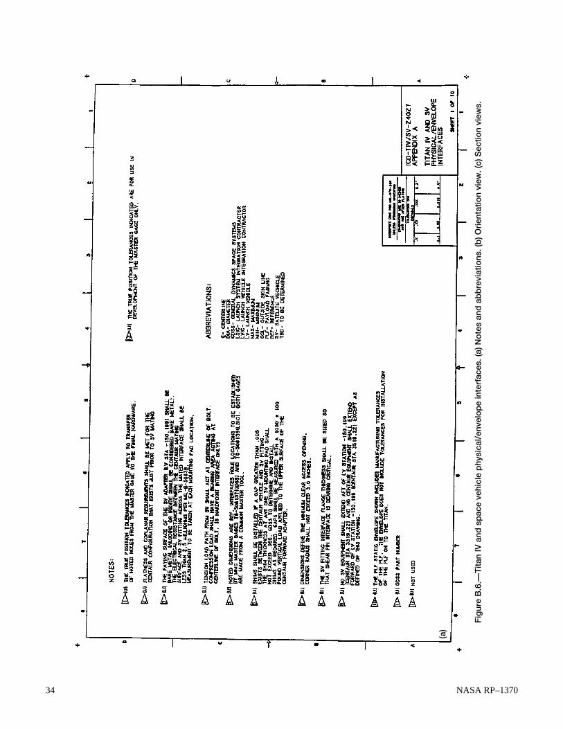
34 NASA RP–1370
Fig
ure
B.6
.—T
itan
IV a
nd s
pac
e ve
hicl
e p
hysi
cal/
enve
lop
e in
terf
aces
. (a)
No
tes
and
ab
bre
viat
ions
. (b
) Ori
enta
tion
view
. (c)
Sec
tion
view
s.
(a)

NASA RP–1370 35
Fig
ure
B.6
.—C
ont
inue
d. (
b) O
rien
tatio
n vi
ew.
(b)

36 NASA RP–1370
Fig
ure
B.6
.—C
onc
lud
ed. (
c) S
ectio
n vi
ews.
(c)

NASA RP–1370 37
Upon exchange of design data relating to the Cassini probe itwould be expected that the probe’s maximum envelope wouldbe established and related to the data system of the Titan/Centaur launch vehicle.
This example is basically a one-sided interface. The Titan/Centaur side of the interface is well defined, which is to beexpected considering the maturity of the design. The tendencyshould be resisted, in cases like this, to ignore or place lessemphasis on the definition and documentation of the matinginterface, given the completeness of the launch vehicle side ofthe interface. The mating interface, namely, the spacecraft side,should be completely defined. Otherwise, the spacecraft de-signer will be signing up to design a compatible interface byagreeing with what the interface on the launch vehicle sidelooks like. Although this approach allows freedom to go off and“do independent things,” it lacks the degree of positive control
needed for interface compatibility. The chances for an incom-patibility are much less if the spacecraft side of the interface isdefined. Space vehicle data, stations, and fasteners must beidentified and controlled. The designer of the space vehicle isthen able to commit to the design and production of an interfacethat is defined. The launch vehicle designers can then verifythat the spacecraft interface will mate with the launch vehicleavailable for the spacecraft. Therefore, if the spacecraft dimen-sions are constrained to a maximum size equal to the launchvehicle’s minimum, less a value for environmental effects, etc.,then the two envelopes are compatible.
Since interface data have been provided for the attachmentdetails for the launch vehicle side of the interface, the designof the Cassini adapter for mounting to the Centaur launchvehicle at station –150.199 can be explained by using the Titandesign data.

38 NASA RP–1370
Appendix C
Software Interface Example:Definitions and Timing Requirements for SafetyInhibit Arm Signals
Signal definition
Satellite vehicle (SV)pyro unshort(primary)
SV latch valvearm (primary)
SV pyro unshort(secondary)
SV latch valvearm (secondary)
Radiofrequencymonopropellant driverbackup enable
Centaur sequencecontrol unit
switch number
45
33
89
88
34
Initiating event + time
Main engine cutoff(MECO) 2 + 3±0.5 sec
MECO2 + 10±0.5 sec
MECO2 + 15±0.5 sec
MECO2 + 17±0.5 sec
Titan IV/Centaurseparation + 24±0.5 sec
Persistence
3±0.5 sec
3±0.5 sec
3±0.5 sec
3±0.5 sec
3±0.5 sec
Function
Unshorts SV pyro capacitor banks
Arms safety inhibit relay for SVmain engines
Provides redundant unshort of SVpyro capacitor banks
Provides redundant arm of inhibitrelay for SV main engines
Services backup (redundant to SVground support equipment com-mand) enable of safety inhibit SVfunctions (radiofrequency sourcesand reaction control system thrusterdrivers)

NASA RP–1370 39
Appendix D
Supplied Services Interface ExampleThis appendix provides a simplistic text-based example of a
supplied services (air-conditioning and cooling water) inter-face control document with a typical design-data-required(DDR) block. This example contains elements condensed froma number of service documents originally used for a submarineweapons program; however, the principles contained herein areuniversally applicable to any complex system of interfaces.Page 1 of the ICD lists the DDR’s (table D.1) showing DDR
numbers, location on the drawing, brief description, and duedate. The DDR block (fig. D.1) on the drawing expands on thisinformation and identifies supplier, user, and time urgency ofthe data needed. The DDR numbering convention used here is“V09 = Void #09.” Preceding the void number with the ICDnumber provides a program-unique DDR number that is easilyrelated to its associated ICD and easily maintained in a database.
Voidnumber
V01
A
V09
A
Location
Sheet 1,zone C–7
Description
Main heatingand cooling(MHC) waterschedule
Date due
30 Days afterauthentication ofdata fulfillingDDR 5760242–V12
TABLE D.1.—DESIGN-DATA-REQUIRED SUMMARYAND LOCATOR
Figure D.1.—Typical design-data-required block.
DDR No. 1466134–V09 Data required: Data supplier: Data user: Date due:
Heating and cooling (HC) system upper zone water schedule (supply water temperature versus environmental temperature) HC working group Launch vehicle design agent 30 days after authentication of data fulfilling DDR No. 2543150–V12

40 NASA RP–1370
The following pages present the kinds of data required to fullydefine the air-conditioning requirements for suites of equip-ment located in a launch control center. Table D.2 detailsconditioned-air distribution; table D.3 presents typical inter-face data required to ensure that a cooling water service isprovided to electrical equipment and indicates requirements forthe equipment before and after the incorporation of an engi-neering change.
701. Launch vehicle control center services:A. Air-conditioning shall be provided with a dedicated
closed-circuit system capable of supplying a mini-mum total flow of 12 820 scfm with a 50% backupcapability.1. The conditioned air shall be distributed to each
equipment flue as specified in table D.2. The distrib-uted conditioned air at the inlet to the equipmentshall satisfy the following parameters:a. Temperature: The minimum temperature shall be
65 °F and the maximum, 70 °F.b. Humidity: The maximum humidity shall be 75
grains per pound of dry air.c. Working pressure: The working pressure shall
be enough to overcome equipment pressure dropsand to maintain positive pressure at the equip-ment outlet with respect to compartment ambi-ent pressure. A 10% minimum leakage rate in thecompartment shall be assumed.
d. Flow resistance: The system shall be able to over-come the pressure drop across the equipment (i.e.,from exit of orifice plate to top of equipment) asshown in table D.2.
e. Flow profile:(1) The flow distribution for each flue shall besuch that the flow velocity between the fluecenterline and 1.3 in. from the edge of the flue,and (where equipment permits) 6 in. above theflue gasket, shall not be less than 80% of theachieved average flow velocity. The achievedaverage flow velocity must equal or exceed veloc-ity based on the minimum flow rate specified intable D.2.(2) Velocity profiling is not required for fluesdesignated 301 through 310, 011 through 015,446BC, 405–2A, 405–2B, 405–6A, and 405–6B.
f. Adjustment capability: The system shall provideflow adjustment from 0 to 300 scfm at each of theequipment flues requiring velocity profiling.
g. Air quality: Air at the inlet to the equipment shallbe equivalent to or better than air filtered througha 0.3-µm filter with an efficiency of 95%.
2. The closed-loop system shall have the capacity ofremoving 52.8 kW (minimum) of heat dissipated byequipment using closed-circuit conditioned air. Thisheat load includes 1.3 kW reserved for launcherequipment in the launch vehicle control center (seenote 702 below).
702. The system shall provide the capability of removing1.65 kW minimum of heat dissipated by equipment by usingcompartment ambient air as a cooling medium while maintain-ing the compartment within specified limits.
A. The ship shall take no action that eliminates the optionfor launcher equipment to use compartment ambient airor closed-circuit conditioned air for dissipating launcher-generated heat of 1.3 kW.
B. Heat dissipated to ambient air by equipment usingclosed-circuit conditioned air is not included.
703. The system shall provide distribution trunks to equip-ment flues with total flow capacity as designated below for theconditions of table D.2:
704. Flow at reference designations marked with an asteriskin table D.2 are to be considered flow reserve capabilities.These designated flues do not require verification of flow pertable D.2 nor profiling per note 701.A.1.e(1) until these fluesare activated. The Government-furnished pipe assemblies andcaps will be supplied for flues not activated.
705. The minimum flow for flues 446BC and 447BC is100 scfm before change 30175 and 250 SCFM after change30175.
Trunk
ABCDEF
Minimumflow,scfm
270016202300340013001500
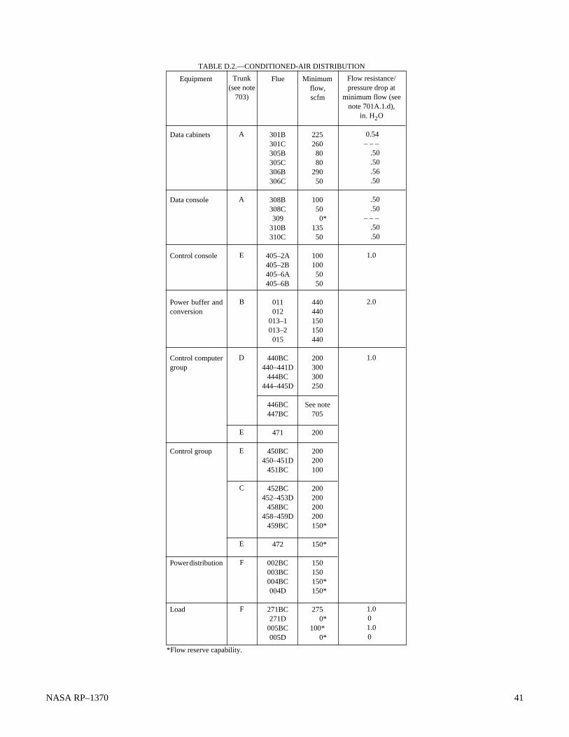
NASA RP–1370 41
Equipment
Data cabinets
Data console
Control console
Power buffer andconversion
Control computergroup
Control group
Power distribution
Load
Minimumflow,scfm
225260 80 80290 50
100 50
0*135 50
100100 50 50
440440150150440
200300300250
See note705
200
200200100
200200200200
150*
150*
150150
150* 150*
275 0*100* 0*
Trunk(see note
703)
A
A
E
B
D
E
E
C
E
F
F
Flue
301B301C305B305C306B306C
308B308C309
310B310C
405–2A405–2B405–6A405–6B
011012
013–1013–2015
440BC440–441D
444BC444–445D
446BC447BC
471
450BC450–451D
451BC
452BC452–453D
458BC458–459D
459BC
472
002BC003BC004BC004D
271BC271D
005BC005D
TABLE D.2.—CONDITIONED-AIR DISTRIBUTION
Flow resistance/pressure drop at
minimum flow (seenote 701A.1.d),
in. H2O
0.54– – – .50 .50 .56 .50
.50 .50– – – .50 .50
1.0
2.0
1.0
1.0 0
1.0 0
*Flow reserve capability.

42 NASA RP–1370
Water flow rate
a6.0-gal/min nominal total flow for two ESGN binnacles and one GSS binnacle. The supply shall maintain constant flow of 2.0 gal/min ±10% to each binnacle.
bA remote, low-flow alarm shall be pro- vided for the ESGN binnacles and the GSS binnacle.
2.6-gal/min minimum
a4.0-gal/min nominal total flow for two ESGN binnacles. The supply shall main- tain a constant flow of 2.0 gal/min ±10% to each binnacle.
bA remote, low-flow alarm shall be pro- vided for the ESGN binnacles.
4.5-gal/min minimum
Minimum coolingcapability
2.25-kW gain
3.25-kW gain
1.5-kW gain
4.0-kW gain
Remarks
Reliability of water supply shall support a navigationsubsystem availability of 0.97. This service requirementshall be continuously available during patrol and refit.The water temperature shall not vary by more than6 deg F when changing at the rate of 0.25 deg F/secmaximum. This change shall not occur more than onceper 30-min period.
TABLE D.3.—WATER FLOW RATE INTERFACE PARAMETERS
[Water inlet temperature: 54 °F max and 48 °F min; temperature alarm set at 56 °F ±1 deg F (increasing) and 47 °F ± 1 deg F (decreasing); see Remarks.Working pressure: 85 psig max and 57 psig min. Test pressure, 125 psig max with binnacles to be isolated at vehicle hydrostatic test.
Pressure drop: nominal differential pressure range, 13 to 23 psid ref. Water quality: dual filters required;filters to 10 µm with 98% efficiency by weight, 20 µm absolute.]
Function
Electrostatically supportedgyro navigator (ESGN) andgravity sensor system (GSS)binnacle cooling
Reserve capability for futurenavigation development
ESGN binnacle cooling
Reserve capability for futurenavigation development
aThe system shall provide test connections at the inlet and outlet of each binnacle to permit periodic measurement of differential pressure.bLocal flow indication shall be provided for each binnacle.

NASA RP–1370 43
Appendix E
Compatibility AnalysisE.1 Definition
Compatibility analysis of the interface definitions contained inan ICD is a major tool of interface control. It serves a twofoldpurpose:
1. Demonstrates completeness of interface definition. If anyinterface data are missing or presented in a manner that cannot beintegrated by using the ICD alone as a data source, the ICD isconsidered deficient.
2. Provides a record (traceability) that the interface has beenexamined and found to have the right form and fit. This recordcan then be used in evaluating the acceptability of subsequentchange proposals.
E.2 Kinds of Data
The following compilation identifies the kinds of data thatmust be obtained for a compatibility analysis and outlines thegeneral steps that should be followed for three categories ofinterface: electrical/functional, mechanical/physical, software,and supplied services:
I. Interface category—electrical/functionalA. Data required to perform analyses
1. The following parameters are required, consideringthe specific function or signal involved:a. Cabling and connectorsb. Power requirementsc. Electromagnetic interference, electromagnetic compatability, electromagnetic radiation, andgrounding requirements
d. Functional flow and timing requirementse. Signal definitionf. Digital data definition to the bit levelg. Protocol levelsh. Seven-layer International Standards Organization open systems instruction stack definition or its equivalenti. Error recovery proceduresj. Startup and shutdown sequencesk. Adequacy of standards used or referenced
2. Unique requirements for an interface or a piece ofequipment different from overall system require-ments (i.e., the hierarchy of specifications required)
3. Adequate definition of all signals crossing the inter-face. “Adequate” is difficult to define precisely but
depends on the signal type (e.g., analog or digital)and the intended use. In general, the interface mustshow the characteristics of the isolating device (ele-ment) on each side of the interface and define thesignal characteristics in engineering terms suitablefor the particular type of signal.
4. Timing and other functional interdependencies5. System handling of error conditions6. Full definition of any standards used. Most digital
transmission standards have various options thatmust be selected; few, if any, standards define thedata that are passed.
B. Steps to be followed1. Verify interoperability of connectors.2. Size cables to loads.3. Determine cable compatibility with signal and envi-
ronmental conditions.4. Define data in one document only.5. Determine adequency of circuit protection devices
and completeness of signal definition.II. Interface category—mechanical/physical
A. Type of interface—form and fit1. Data required to perform analysis
a. A datum (reference) that is common to both sidesof the interface (e.g., a mounting hole in one partthat will mate with a hole or fastener in the othermating parts or a common mating surface of thetwo mating parts)
b. Dimensions and tolerances for all features of eachpart provided in a manner that gives the optimuminterface fit and still provides the required designfunctions. Optimum interface means dimension-ing so that the tolerance accumulation is kept to aminimum.
2. Steps to be followeda. Start with the common datum and add and subtract
dimensions (adding the tolerance accumulationsfor each dimension) for each feature of the partinterface.
b. Determine the dimensional location of theinterface-unique features by adding and subtract-ing the tolerance accumulations from resultingdimensions to achieve the worst-case maximumand minimum feature definitions.
c. Perform the same analysis for the mating featuresof the interfacing part.
d. Compare and question the compatibility of theworse-case features of the two mating parts (Will

44 NASA RP–1370
functional ICD. The purpose of an ICD is to communi-cate equipment interface requirements to programmersin terms that the programmers readily and accuratelyunderstand and to require equipment designers to con-sider the effect of their designs on computer programs.
B. Type of interface—hardware/software integration. TheICD provides an exact definition of every interface, bymedium and by function, including input/outputcontrol codes, data format, polarity, range, units, bitweighting, frequency, minimum and maximum timingconstraints, legal/illegal values, accuracy, resolution,and significance. Existing documentation may be ref-erenced to further explain the effect of input/outputoperations on external equipment. Testing required tovalidate the interface designs is also specified.
IV. Interface category—supplied servicesA. Type of interface—fluid service
1. Data required to perform analysisa. Type of fluid required by the equipment and
type of fluid the service supplier will provide.This may be in the form of a Federal or militaryspecification or standard for both sides or forone side of the interface.
b. Location of the equipment/service interface(hose connection, pipe fitting, etc.)
c. Equipment requirements at the interface loca-tion in regard to characteristics (pressure, tem-perature, flow rate, duty cycle, etc.)
d. Capability of the service supplier at the interfacelocation
e. Manner in which the equipment can affect thecapability of the service supplier (e.g., having alarge backpressure that the supplier fluid mustpush against or a combination of series andparallel paths that the supplier fluid must passthrough)
2. Steps to be performed. Examine the supplier andequipment requirements to determinea. If the supplier capability meets or exceeds the
equipment requirements. This may require con-verting a Federal/military specification or stan-dard requirement into what is specified for theequipment.
b. If the supplier capability meets the require-ments, considering the effects resulting from thefluid passing through the mating equipment
B. Type of interface—environmental1. Data required to perform analysis
a. Conditions required for equipment to functionproperly. Storage, standby, and operatingscenarios need to be established and defined.
b. Supplier’s capability to provide the environ-ment specified in terms of time to reach steady
the maximum condition of one part fit within theminimum condition of the mating part?)
B. Type of interface—structural load1. Data required to perform analysis
a. A description of the loading conditions (static ordynamic) and the duration of those conditions
b. Characteristics of the equipment involved: weightor mass; mass distribution; elastic properties; andsensitivity of elastic properties to temperature,moisture, atmospheric gas content, pressure, etc.
2. Steps to be followed. This analysis involves placingthe interfacing items in a position that produces themaximum loads while the items are interfacing. Aspace experiment is primarily designed for flightloads, yet it must withstand the loads developedduring the launch and deployment cycles and per-haps unique loads during launch processing. Thecomplexity of the compatibility analysis will varydepending on the types of interfacing items andenvironments.a. Attachment loads are the simplest, being a state- ment of the loads applied by the attaching feature
(bolt) and the load capability of the componentbeing retained (flange).
b. Hoisting and handling loads require the calcula-tion of bending moments or shear for variousloading scenarios. Dynamic and environmentalloads must also be considered. (How quickly is theload applied? What are the wind loading factors?)
c. A more complex situation will be the loads devel-oped during a dynamic interaction of interfacingitems where different material characteristics mustbe considered along with the reaction characteris-tics of the materials (e.g., a flexible beam ofvarying moments of inertia supported by an elas-tomeric medium where the entire system issubjected to a high-velocity impulse of a fewmicroseconds duration). Such a condition couldproduce loads that exceed those for which one ofthe interfacing items is designed. Another inter-facing item may have to be redesigned so as not tojeopardize the mission of the primary item (i.e.,increasing the strength of the item being supportedcould increase the weight).
III. Interface category—softwareA. Type of interface—software. The ICD is required to
specify the functional interface between the computerprogram and any equipment hardware with which itmust operate. Often, the supplier documentation forstandard computer peripherals and terminals is ad-equate for this purpose. Conversely, it has been foundthat performance specifications governing the designof new equipment are not satisfactory for use in a

NASA RP–1370 45
state from transients resulting from uncontrol-lable external environments; the limits of thesteady-state conditions (maximum/minimum);and monitoring features
2. Steps to be performed. Perform analyses (e.g.,thermal) under extreme and nominal environmen-tal conditions to verify that supplier’s equipmentcan maintain the environment required for theequipment. The complexity of the analysis mayvary depending on the types of items involved.
a. Simple inspection, which considers the environ-ment required by an item versus the capability ofthe ambient in which the item resides
b. Complex analysis, which must consider uncon-trolled external environmental inputs, the ther-mal properties of intermediate systems that donot contribute to the end environment but act asconduits or resistors in the model, and the inter-action of the item and the system that controlsthe desired environment

46 NASA RP–1370
Appendix F
Bracket System for Interfaces Brackets are used on hardware/engineering drawings to flag
or identify details controlled by the ICD. Changes cannot bemade to the drawings or designs without the effects on theinterface being assessed and coordinated through the ICDprocess.
The process uses a rating similar to that used in the problem/failure reporting bracket system with the same controls andtraceability. Once a bracket has been assigned to an interfacevoid or problem, specific analyses and actions are required forthe bracketed item to be removed. The bracketed item remainsin open status with assignment to the responsible cognizantsubsystem or design section until (1) the corrective action orcoordinated information has been developed, (2) a proper riskassessment has been performed, (3) ICD change actions havebeen completed, (4) adequate verification of the interface isplanned, and (5) the proper approval signatures have beenobtained.
The following ratings are used to establish a category of“bracket” identifiers for interface deficiencies. Any discrep-ancy having an A rating greater than 1 or a B rating greater than2 will be designated a bracketed discrepancy (see figure F.1).
I. Interface deficiency rating A (S&MA impact)A. Rating A1: Negligible effect on interface or mission
performance1. No appreciable change in functional capability (form,
fit, and function are adequate for the mission)2. Minor degradation of engineering or science data3. Support equipment or test equipment failure but not
mission-critical element failure4. Support-equipment- or test-equipment-induced
failures
5. Drawing errors not affecting element constructionB. Rating A2: Significant degradation to interface or
mission performance1. Appreciable change in functional capability2. Appreciable degradation of engineering or science
data3. Significant operational difficulties or constraints4. Decrease in life of interfacing equipment5. Significant effect on interface or system safety
C. Rating A3: Major degradation to interface or missionperformance or catastrophic effect on interface orsystem safety
II. Interface deficiency rating B (understanding of risk)A. Rating B1: Effect of interface deficiency is identified
by analysis or test, and resolution or correctiveaction is assigned and scheduled or implementedand verified. There is no possibility of recurrence.
B. Rating B2: Effect of interface deficiency is not fullydetermined. However, the corrective action proposed,scheduled, or implemented is considered effective incorrecting the deficiency. There is minimal possibilityof recurrence and little or no residual risk.
C. Rating B3: Effect of interface deficiency is wellunderstood. However, the corrective changes pro-posed do not completely satisfy all doubts or concernsregarding the correction, and the effectiveness ofcorrective action is questionable. There is some poss-ibility of recurrence with residual risk.
D. Rating B4: Effect of interface deficiency is not wellunderstood. Corrections have not been proposed orthose proposed have uncertain effectiveness. There issome possibility of recurrence with residual risk.

NASA RP–1370 47
Rating A (S&MA impact)
Numerical rating Rating B (understanding of risk)
Negligible impact Significant degradation Major degradation
Known deficiency with corrective action assigned, scheduled, and implemented Deficiency poorly defined but acceptable corrective action proposed, scheduled, and implemented (low residual risk) Known deficiency but effectiveness of corrective action is unclear and does not satisfy all doubts and concerns (residual risk) Impact not defined with confidence; corrective action with uncertain effectiveness (residual risk)
1 1 2 2 3 3 4
Interface discrepancy red flag; project or task manager approval required
Figure F.1.—Interface deficiency rating system.

48 NASA RP–1370
Appendix G
ICD Guidelines
1. Interface control documents should not require the designer of themating interface to assume anything. ICD’s should be compatible witheach other and stand alone.
2. Only the definition that affects the design of the mating interfacesneed be used.
3. ICD’s should not specify design solutions.
4. The ICD custodian should be independent of the design organiza-tion.
5. The ICD custodian should verify that the data being controlled byan ICD are sufficient to allow other organizations to develop theinterface described by the ICD.
6. An interface control system should be in place at the beginning ofsystem (hardware or software) development.
7. Each void should have a unique sequential identifier establishingdue dates, identifying exact data to be supplied, and identifying the datasupplier.
NASA RP–1370 49
Appendix H
Glossarybaseline—The act by which the program manager or a desig-nated authority signs an interface control document (ICD) andby that signature establishes the genuineness of the ICD as anofficial document defining the interface design requirements.The term “baseline” conveys the idea that the ICD is the onlyofficial definition and that this officiality comes from thetechnical management level. Not only is the initial version ofthe ICD baselined, but each change to an ICD is likewiseapproved.
comment issue—An issue of an ICD distributed for review andcomment before a meeting of the affected parties and beforebaselining
custodian—The contractor or project assigned the responsibil-ity of preparing and processing an ICD through authenticationand subsequently through the change process
data—Points, lines, planes, cylinders, and other geometricshapes assumed to be exact for the purpose of computation andfrom which the location or geometric relationship (form) offeatures of a piece of equipment can be established
interface responsibility matrix—A matrix of contractors,centers, and project organizations that specifies responsibilitiesfor each ICD listed for a particular task. Responsibilities aredesignated as review and comment, technical approval,baselining, and information.
electrical/functional interface—An interface that defines theinterdependence of two or more pieces of equipment when theinterdependence arises from the transmission of an electricalsignal from one piece of equipment to another. All electricaland functional characteristics, parameters, and tolerances ofone equipment design that affect another equipment design arespecified.
interface—That design feature of one piece of equipment thataffects a design feature of another piece of equipment. Aninterface can extend beyond the physical boundary betweentwo items. (For example, the weight and center of gravity ofone item can affect the interfacing item; however, the center ofgravity is rarely located at the physical boundary. An electricalinterface generally extends to the first isolating element ratherthan terminating at a series of connector pins.)
interface control—The process of (1) defining interface re-quirements to ensure compatibility between interrelated pieces
of equipment and (2) providing an authoritative means ofcontrolling the interface design.
interface control document (ICD)—A drawing or other docu-mentation that depicts physical and functional interfaces ofrelated or cofunctioning items. (The drawing format is the mostcommon means of controlling the interface.)
interface control working group—A group convened tocontrol and expedite interface activity between the Govern-ment, contractors, and other organizations, including resolu-tion of interface problems and documentation of interfaceagreements
interface definition—The specification of the features, char-acteristics, and properties of a particular area of an equipmentdesign that affect the design of another piece of equipment
interoperability —The ability of two devices to exchangeinformation effectively across an interface
mechanical/physical interface—An interface that defines themechanical features, characteristics, dimensions, and toler-ances of one equipment design that affect the design of anothersubsystem. Where a static or dynamic force exists, forcetransmission requirements and the features of the equipmentthat influence or control this force transmission are also de-fined. Mechanical interfaces include those material propertiesof the equipment that can affect the functioning of matingequipment or the system (e.g., thermal and galvaniccharacteristics).
software interface—The functional interface between thecomputer program and any equipment hardware with which itmust operate. Tasking required to validate the interface designsis also specified.
supplied-services interface—Those support requirements thatequipment needs to function and that are provided by anexternal separate source. This category of interface can befurther subdivided into environmental, electrical power, andcommunication requirements.
technical approval—The act of certifying that the technicalcontent in an interface document or change issue is acceptableand that the signing organization is committed to implementingthe portion of the interface design under the signer’s cognizance.

50 NASA RP–1370
FED–STD–209E: Airborne Particulate Cleanliness Classes in Cleanrooms andClean Zones. Federal Standard, Sept. 1992.
KHB 1860.1: Kennedy Space Center Ionizing Radiation Protection Program.Kennedy Space Center, FL, 1972.
MCR–86–2550: Titan IV System Contamination Control Plan. Martin MariettaAerospace Corp., Denver, CO, or Bethesda, MD, 1987.
MIL–B–5087B: Bonding, Electrical and Lightning Protection for AerospaceSystems. Military Standard, Dec. 1984.
MIL–N–7513F: Nomenclature Assignment, Contractor’s Method for Obtain-ing. Military Standard, Notice 2, July 1993.
MIL–HDBK–259: Life Cycle Cost in Navy Acquisitions. Military Handbook,Apr. 1983.
MIL–P–27401C: Propellant Pressurizing Agent, Nitrogen. Military Standard,Aug. 1988.
MIL–S–83490: Specifications, Types and Forms. Military Standard, Oct.1968.
MIL–STD–100E: Engineering Drawing Practices. Military Standard, Sept.1992.
MIL–STD–482A: Configuration Status Accounting Data Elements and Re-lated Features. Military Standard, Sept. 1968.
MIL–STD–973: On Configuration Management Practices for Systems, Equip-ment, Munitions, and Computer Software. Military Standard, 1993.
MIL–STD–1246C: Product Cleanliness Levels and Contamination ControlProgram. Military Standard, Apr. 1994.
MIL–STD–1388–1A: Logistic Support Analysis Reviewer. Military Standard,Mar. 1991.
MIL–STD–1456: Contractor Configuration Management Plans. Sept. 1989.(Cancelled July 1992.)
MIL–STD–1528A: Manufacturing Management Program. Military Standard,Sept. 1986.
MIL–STD–1541: Electromagnetic Compatibility Requirements for SpaceSystems. Military Standard, Dec. 1987.
PD 699–120: Cassini Final Targeting Specification. Program Directive, NASAor Executive Office of the President.
SECNAVINST 4130: Navy Configuration Management Manual. ExecutiveOffice of the Secretary of the Navy.
References1. MIL–STD–499: Engineering Management. May 1974.2. Blanchard, B.S.; and Fabrycky, W.J.: Systems Engineering and Analysis.
Prentice-Hall Inc., 1981.3. MIL–STD–1521B: Technical Reviews and Audits for Systems, Equip-
ment, and Computer Software, Notice 1, Dec. 1985.4. Kockler, F.; Withers, T.; Poodiack, J.; and Gierman, M.: Systems Engi-
neering Management Guide. Defense Systems Management College,Fort Belvior, VA, Jan. 1990.
5. ICD–Titan IV/Satellite Vehicle–24027, Cassini Mission. Martin MariettaTechnologies, Inc., Denver, CO, Jan. 1994.
6. MIL–STD–490A: Specification Practices. Military Standard, June 1985.7. ANSI Standard Y14.5: Dimensioning and Tolerancing.8. DOD–STD–100: Engineering Drawing Practices.9. SAMSO–STD 77–4: Format and Requirements for Interface Documents.
Space & Missile Systems Org., Jan. 1979.10. MIL–STD–704: Aircraft Electrical Power Characteristics.
BibliographyAFR 65–3, AR 70–37, NAVELEXINST 4130.1, and 4139.1A: Joint ServicesRegulation on Configuration Management. Air Force Regulation, Naval Elec-tronics Systems Instructions, Marine Corp Order.
AFSCP 800–7: Configuration Management. Air Force Systems CommandPamphlet.
DOD 4120.3–M: Defense Standardization and Specification Program Policies,Procedures and Instructions, Aug. 1978.
DOD 4245.7–M: Transition From Development to Production. Military Speci-fication, Sept. 1985.
DOD 5010.19: Configuration Management. Military Specification, July 1990.
DOD–D–1000B: Drawings, Engineering and Associated Lists. Military Speci-fication, July 1990.
DOD–STD–480B: Configuration Control—Engineering Changes, Deviations,and Waivers, July 1988. (Cancelled July 1992.)
ESMC Req 160–1: Radiation Protection Program. Eastern Space & MissileCenter, Patrick AFB, FL.
Fairley, R.E.: Software Engineering Concepts. McGraw-Hill, New York,1985.

NASA RP–1370 51
Training AnswersChapter Answers
1 1(A); 2(D); 3(C); 4a(C), 4b(A), 4c(B)
2 1(D); 2(C); 3a(B), 3b(C); 4a(C), 4b(C), 4c(C);
5a(A), 5b(A), 5c(A); 6a(C), 6b(A), 6c(A);
7a(B), 7b(B), 7cA(i), 7cB(ii), 7cC(i); 8a(B),
8b(A); 9a(A), 9b(A), 9c(B)
3 1a(A), 1b(B), 1c(B); 2a(B), 2b(A), 2c(B);
3a(A), 3b(B), 3c(A); 4a(B), 4b(A), 4c(B);
5a(A), 5b(B); 6a(A), 6b(B), 6c(B), 6d(B);
7a(B), 7b(A), 7c(A), 7d(A), 7e(A)
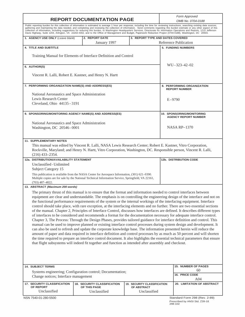
REPORT DOCUMENTATION PAGE
2. REPORT DATE
19. SECURITY CLASSIFICATION OF ABSTRACT
18. SECURITY CLASSIFICATION OF THIS PAGE
Public reporting burden for this collection of information is estimated to average 1 hour per response, including the time for reviewing instructions, searching existing data sources,gathering and maintaining the data needed, and completing and reviewing the collection of information. Send comments regarding this burden estimate or any other aspect of thiscollection of information, including suggestions for reducing this burden, to Washington Headquarters Services, Directorate for Information Operations and Reports, 1215 JeffersonDavis Highway, Suite 1204, Arlington, VA 22202-4302, and to the Office of Management and Budget, Paperwork Reduction Project (0704-0188), Washington, DC 20503.
NSN 7540-01-280-5500 Standard Form 298 (Rev. 2-89)Prescribed by ANSI Std. Z39-18298-102
Form Approved
OMB No. 0704-0188
12b. DISTRIBUTION CODE
10. SPONSORING/MONITORING AGENCY REPORT NUMBER
8. PERFORMING ORGANIZATION REPORT NUMBER
5. FUNDING NUMBERS
3. REPORT TYPE AND DATES COVERED
4. TITLE AND SUBTITLE
6. AUTHOR(S)
7. PERFORMING ORGANIZATION NAME(S) AND ADDRESS(ES)
9. SPONSORING/MONITORING AGENCY NAME(S) AND ADDRESS(ES)
11. SUPPLEMENTARY NOTES
12a. DISTRIBUTION/AVAILABILITY STATEMENT
13. ABSTRACT (Maximum 200 words)
14. SUBJECT TERMS
17. SECURITY CLASSIFICATION OF REPORT
16. PRICE CODE
15. NUMBER OF PAGES
20. LIMITATION OF ABSTRACT
Unclassified Unclassified
Reference Publication
Unclassified
National Aeronautics and Space AdministrationLewis Research CenterCleveland, Ohio 44135–3191
National Aeronautics and Space AdministrationWashington, DC 20546–0001
1. AGENCY USE ONLY (Leave blank)
January 1997
NASA RP–1370
E–9790
WU–323–42–02
A04
60Systems engineering; Configuration control; Documentation;Change notices; Interface management
Training Manual for Elements of Interface Definition and Control
Vincent R. Lalli, Robert E. Kastner, and Henry N. Hartt
The primary thrust of this manual is to ensure that the format and information needed to control interfaces betweenequipment are clear and understandable. The emphasis is on controlling the engineering design of the interface and not onthe functional performance requirements of the system or the internal workings of the interfacing equipment. Interfacecontrol should take place, with rare exception, at the interfacing elements and no further. There are two essential sectionsof the manual. Chapter 2, Principles of Interface Control, discusses how interfaces are defined. It describes different typesof interfaces to be considered and recommends a format for the documentation necessary for adequate interface control.Chapter 3, The Process: Through the Design Phases, provides tailored guidance for interface definition and control. Thismanual can be used to improve planned or existing interface control processes during system design and development. Itcan also be used to refresh and update the corporate knowledge base. The information presented herein will reduce theamount of paper and data required in interface definition and control processes by as much as 50 percent and will shortenthe time required to prepare an interface control document. It also highlights the essential technical parameters that ensurethat flight subsystems will indeed fit together and function as intended after assembly and checkout.
This publication is available from the NASA Center for Aerospace Information, (301) 621–0390.Multiple copies are for sale by the National Technical Information Service, Springfield, VA 22161,
(703) 487–4822.
Unclassified -UnlimitedSubject Category 15
This manual was edited by Vincent R. Lalli, NASA Lewis Research Center; Robert E. Kastner, Vitro Corporation,Rockville, Maryland; and Henry N. Hartt, Vitro Corporation, Washington, DC. Responsible person, Vincent R. Lalli,(216) 433–2354.