Embed Size (px)
Citation preview
Training LHC Powering Luigi Serio
CRYOGENICS AND POWERING
L. Serio
AT/ACR
2Training LHC Powering Luigi Serio
Contents
• Cryogenic system introduction
• What does the cryogenic system need to do its job?
• Conditions to start powering: CRYO_START
• When do we have to stop powering: CRYO_MAINTAIN
• Quench and quench recovery
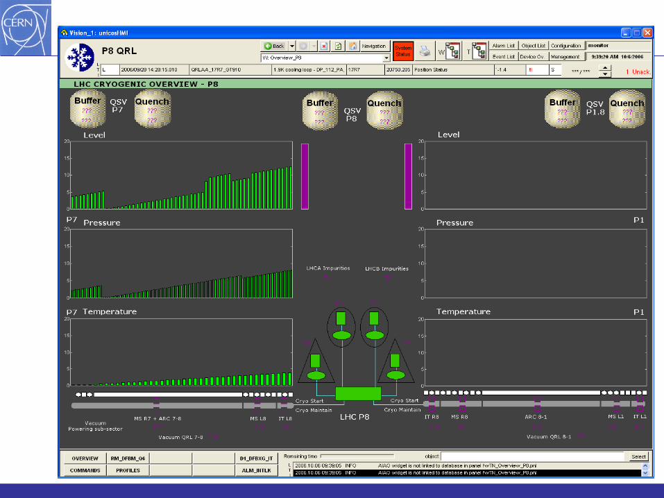
• How operators get an overview of the cryo process
• What instrumentation is available to understand quenches?
3Training LHC Powering Luigi Serio
LHC Cryogenic system operation
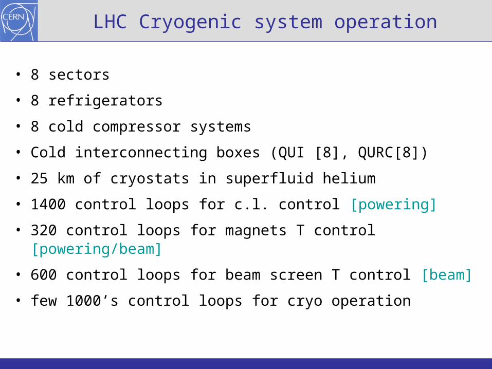
• 8 sectors
• 8 refrigerators
• 8 cold compressor systems
• Cold interconnecting boxes (QUI [8], QURC[8])
• 25 km of cryostats in superfluid helium
• 1400 control loops for c.l. control [powering]
• 320 control loops for magnets T control [powering/beam]
• 600 control loops for beam screen T control [beam]
• few 1000’s control loops for cryo operation
4Training LHC Powering Luigi Serio
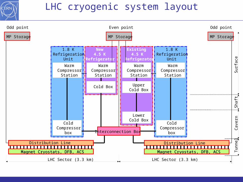
LHC cryogenic system layout
UpperCold Box
Cold Box
WarmCompressor
Station
LowerCold Box
Magnet Cryostats, DFB, ACS Magnet Cryostats, DFB, ACS
ColdCompressor
box
Sh
aft
Su
rfa
ceC
ave
rnT
un
ne
l
LHC Sector (3.3 km) LHC Sector (3.3 km)
1.8 KRefrigeration
Unit
New4.5 K
Refrigerator
Existing4.5 K
Refrigerator
1.8 KRefrigeration
Unit
WarmCompressor
Station
WarmCompressor
Station
WarmCompressor
Station
ColdCompressor
box
Even pointOdd point Odd point
MP StorageMP Storage MP Storage
UpperCold Box
Interconnection Box
Cold Box
WarmCompressor
Station
LowerCold Box
Distribution Line Distribution Line
Magnet Cryostats, DFB, ACS Magnet Cryostats, DFB, ACS
ColdCompressor
box
5Training LHC Powering Luigi Serio
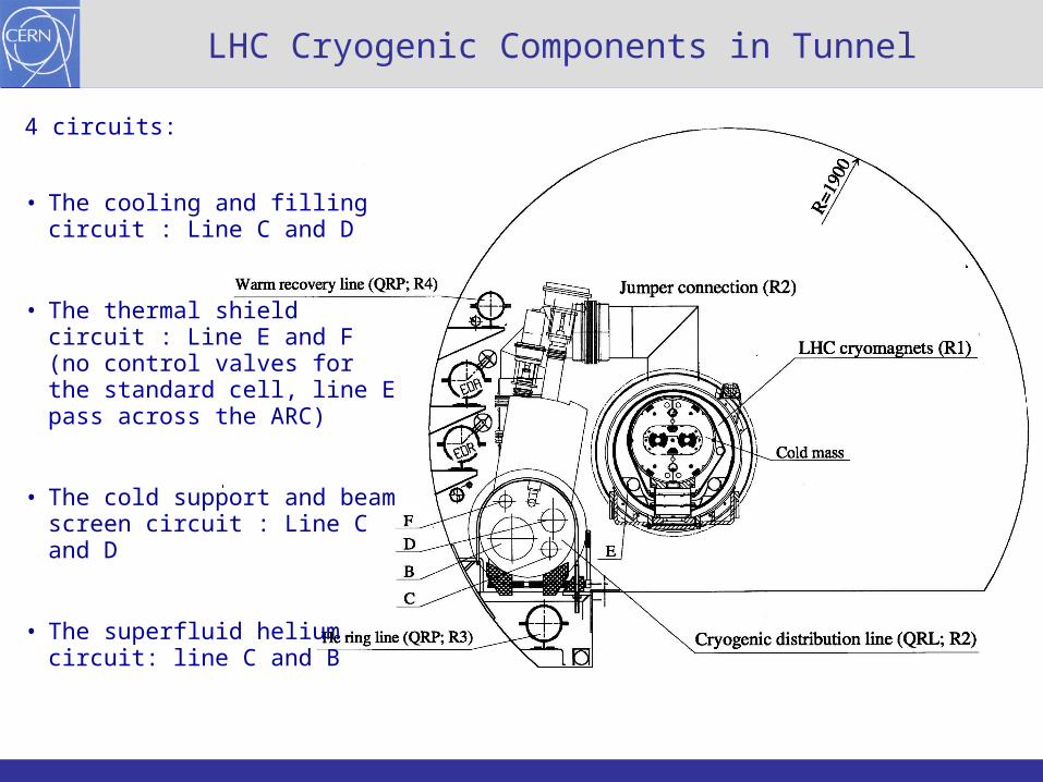
LHC Cryogenic Components in Tunnel
4 circuits:
• The cooling and filling circuit : Line C and D
• The thermal shield circuit : Line E and F (no control valves for the standard cell, line E pass across the ARC)
• The cold support and beam screen circuit : Line C and D
• The superfluid helium circuit: line C and B
6Training LHC Powering Luigi Serio
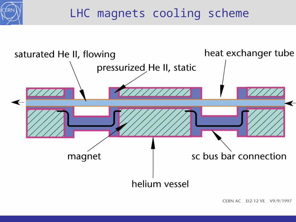
LHC magnets cooling scheme
7Training LHC Powering Luigi Serio
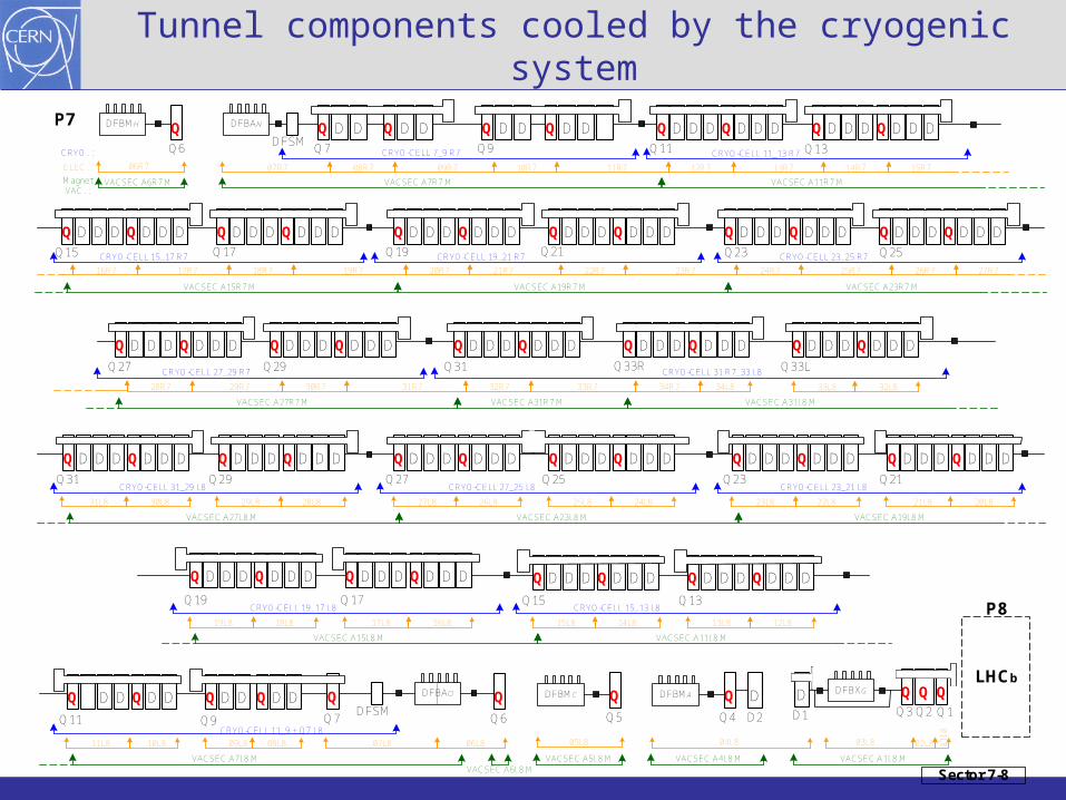
Tunnel components cooled by the cryogenic system
Q
Q D DQ D DQDFBMH DFBAN Q D DQ D D D DDD D QQD D DDD D QQD
D DDD D QQD D DDD D QQD D DDD D QQD D DDD D QQD D DDD D QQD D DDD D QQD
D DDD D QQD D DDD D QQD D DDD D QQD D DDD D QQD D DDD D QQD
D DDD D QQD D DDD D QQD
Q6DFSM
Q7 Q9 Q11 Q13
Q15 Q17 Q19 Q21 Q23 Q25
Q27 Q29 Q31 Q33R Q33L
Q31 Q29 Q27 Q25 Q23 Q21
Q19 Q17 Q15 Q13
QQQ3
QQ1Q2
DFBXGDD1
DQQ4 D2
DFBMAQDFBMC
Q5
QQ6
DFBAO
DFSMDDD QQD
Q11
DDD D QQQ7Q9
D DDD D QQD D DDD D QQD D DDD D QQD D DDD D QQD
D DDD D QQD D DDD D QQD D DDD D QQD D DDD D QQD
CRYO-CELL 11_13 R7CRYO-CELL 7_9 R7
CRYO-CELL 15_17 R7 CRYO-CELL 19_21 R7 CRYO-CELL 23_25 R7
CRYO-CELL 27_29 R7 CRYO-CELL 31 R7_33 L8
CRYO-CELL 31_29 L8 CRYO-CELL 27_25 L8 CRYO-CELL 23_21 L8
CRYO-CELL 19_17 L8 CRYO-CELL 15_13 L8
CRYO-CELL 11_9 + Q7 L8
Sector 7-8
LHCb
08R7 09R7 10R7 11R7 12R7 13R7 14R7 15R7
16R7 17R7 18R7 19R7 20R7 21R7 22R7 23R7 24R7 25R7 26R7 27R7
28R7 29R7 30R7 31R7 32R7 33R7 34R7 34L8 33L8 32L8
31L8 30L8 29L8 28L8 27L8 26L8 25L8 24L8 23L8 22L8 21L8 20L8
19L8 18L8 17L8 16L8 15L8 14L8 13L8 12L8
11L8 10L8 09L8 08L8 07L8 06L8 05L8 04L8 03L8 02L8
01
L8
07R706R7
VACSEC.A7R7.M VACSEC.A11R7.M
VACSEC.A15R7.M VACSEC.A19R7.M VACSEC.A23R7.M
VACSEC.A27R7.M VACSEC.A31R7.M VACSEC.A31L8.M
VACSEC.A27L8.M VACSEC.A23L8.M VACSEC.A19L8.M
VACSEC.A15L8.M VACSEC.A11L8.M
VACSEC.A7L8.M VACSEC.A1L8.MVACSEC.A5L8.M VACSEC.A4L8.MVACSEC.A6L8.M
VACSEC.A6R7.M
P8
P7
CRYO. :
ELEC. :
MagnetVAC. :
8Training LHC Powering Luigi Serio
Cooling towers
Compressed air
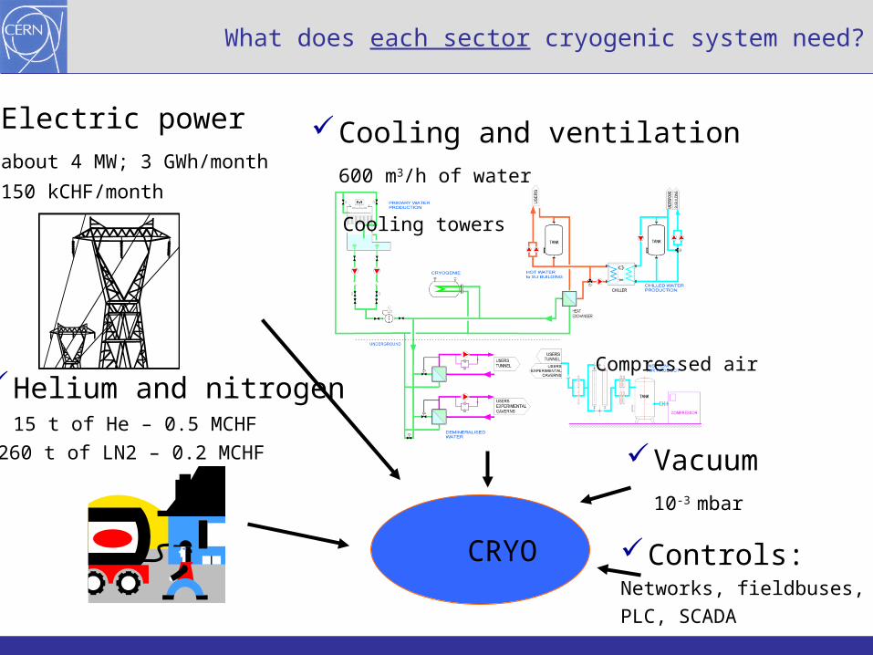
Vacuum10-3 mbar
Cooling and ventilation600 m3/h of water
Helium and nitrogen15 t of He – 0.5 MCHF
1260 t of LN2 – 0.2 MCHF
Electric powerabout 4 MW; 3 GWh/month
150 kCHF/month
What does each sector cryogenic system need?
CRYO Controls:Networks, fieldbuses, PLC, SCADA
9Training LHC Powering Luigi Serio
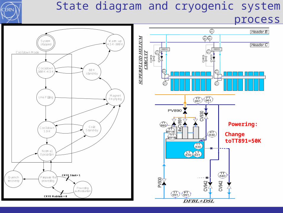
Systemstopped
ColdStand-by
Warm-up4.5 K-300 K
80 Kstand-by
Cool-down1.9 K
LHe FillingMagnet
Emptying
Cool-down300 K-4.5 K
Quenchrecovery
CRYO Start = 1
NormalOperation
Prepare forpowering
Poweringauthorisation
CRYO Maintain = 0
Cool down Mode
State diagram and cryogenic system process
Powering:
Change toTT891=50K
10Training LHC Powering Luigi Serio
CRYO_START (authorization for powering) considerations
• The CRYO_START is a start interlock. Therefore once the conditions are met the powering is authorised without any further acknowledgement. It requires a manual intervention (operator request) by the cryogenic operator. It will also modify the control temperature of the HTS leads.
• The CRYO_START ensures that the required conditions to power the magnets are met.
• It gives sufficient margins to “safely” operate cryogenic equipment (temperatures, pressures, levels).
• It does not protect equipment (it does not replace the quench protection system, the voltage taps, the beam monitors, etc.).
• If the CRYO_START disappears the machine can still safely run for several minutes.
11Training LHC Powering Luigi Serio
CRYO_MAINTAIN (request for slow discharge)
• The CRYO_MAINTAIN is a full stop interlock which cause a slow discharge. An operator acknowledgement is therefore needed to be able to power again the magnets.
• Only the conditions that will directly and rapidly provoke a quench (magnets, current leads, bus-bars) will be considered.
• A filtering logic on the sensor used for CRYO_MAINTAIN will be necessary in order to avoid unnecessary downtime due to failing sensors or electrical noise. In principle it will be based on the verification of 2 out of 3 sensors in the cell requesting the discharge or in the case of only 2 sensors both must be out; the conditions must be valid for at least 30 sec. Instrumentation clearly not functioning (open or short circuit) will be flagged out.
12Training LHC Powering Luigi Serio
Cryogenics conditions for powering
There would be three logic states:
• Conditions to authorize magnet powering
(CRYO_START=TRUE and CRYO_MAINTAIN=TRUE)
• Conditions that do not authorize magnet powering but if there is already current in the magnets there is no request for discharge (the conditions of magnet powering were met at the time of the start of powering but have disappeared meanwhile) (CRYO_START=FALSE and CRYO_MAINTAIN=TRUE)
• Conditions that do not authorise magnet powering and request a slow current discharge
(CRYO_START=FALSE and CRYO_MAINTAIN=FALSE)
Each powering subsector has one CRYO_START and one CRYO_MAINTAIN
13Training LHC Powering Luigi Serio
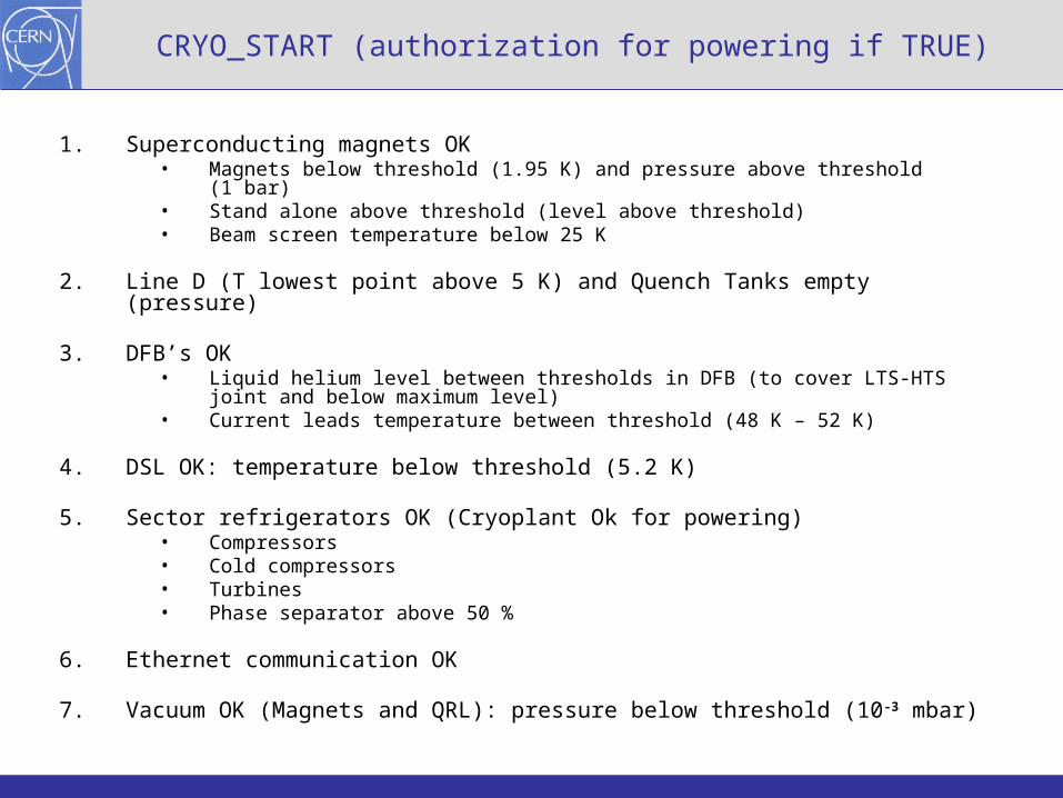
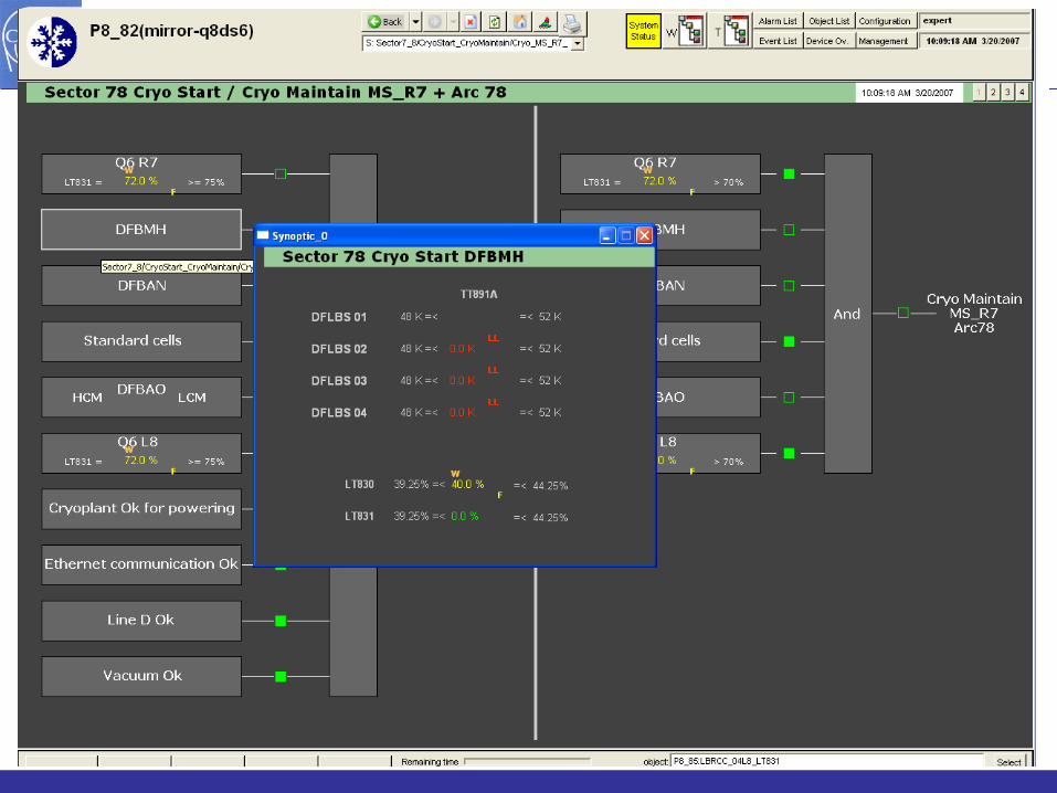
CRYO_START (authorization for powering if TRUE)
1. Superconducting magnets OK• Magnets below threshold (1.95 K) and pressure above threshold (1 bar)• Stand alone above threshold (level above threshold)• Beam screen temperature below 25 K
2. Line D (T lowest point above 5 K) and Quench Tanks empty (pressure)
3. DFB’s OK• Liquid helium level between thresholds in DFB (to cover LTS-HTS joint and below
maximum level)• Current leads temperature between threshold (48 K – 52 K)
4. DSL OK: temperature below threshold (5.2 K)
5. Sector refrigerators OK (Cryoplant Ok for powering)• Compressors• Cold compressors• Turbines• Phase separator above 50 %
6. Ethernet communication OK
7. Vacuum OK (Magnets and QRL): pressure below threshold (10-3 mbar)
14Training LHC Powering Luigi Serio
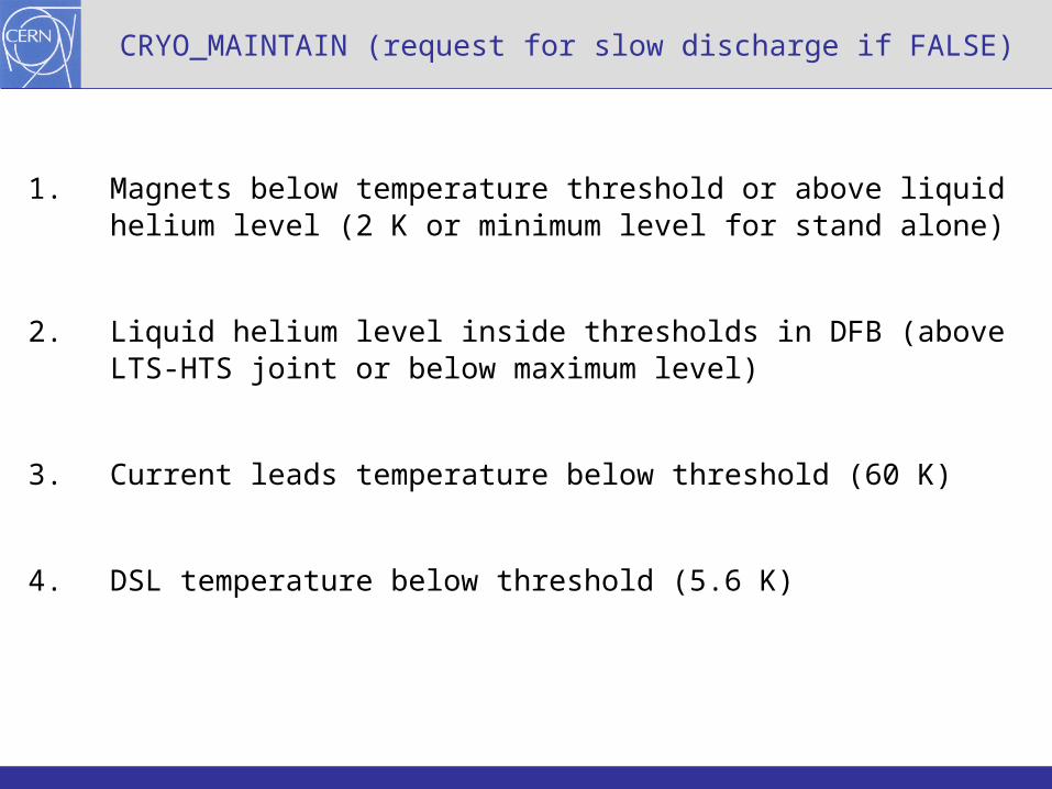
CRYO_MAINTAIN (request for slow discharge if FALSE)
1. Magnets below temperature threshold or above liquid helium level (2 K or minimum level for stand alone)
2. Liquid helium level inside thresholds in DFB (above LTS-HTS joint or below maximum level)
3. Current leads temperature below threshold (60 K)
4. DSL temperature below threshold (5.6 K)
15Training LHC Powering Luigi Serio
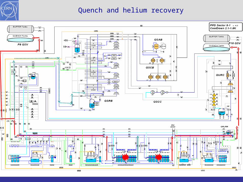
Quench and helium recovery
16Training LHC Powering Luigi Serio
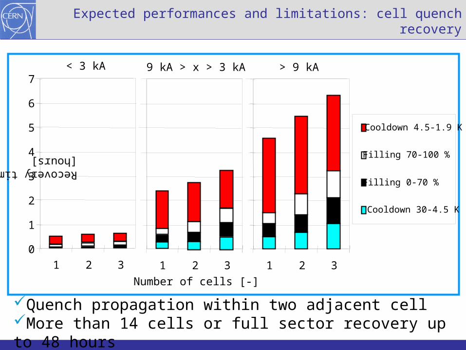
Quench propagation within two adjacent cellMore than 14 cells or full sector recovery up to 48 hours
1 2 3
Number of cells [-]
Cooldown 4.5-1.9 K
Filling 70-100 %
Filling 0-70 %
Cooldown 30-4.5 K
Expected performances and limitations: cell quench recovery
1 2 3
0
1
2
3
4
5
6
7
1 2 3
Recovery time [hours]
< 3 kA 9 kA > x > 3 kA > 9 kA
17Training LHC Powering Luigi Serio
18Training LHC Powering Luigi Serio
19Training LHC Powering Luigi Serio
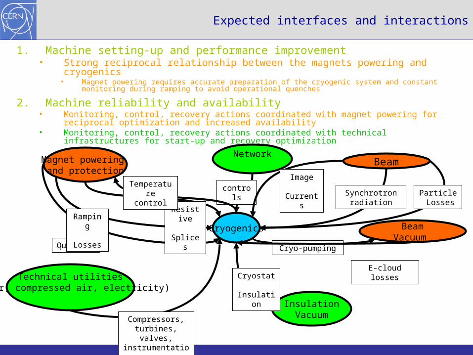
Expected interfaces and interactions
1. Machine setting-up and performance improvement• Strong reciprocal relationship between the magnets powering and cryogenics
• Magnet powering requires accurate preparation of the cryogenic system and constant monitoring during ramping to avoid operational quenches
2. Machine reliability and availability• Monitoring, control, recovery actions coordinated with magnet powering for reciprocal
optimization and increased availability• Monitoring, control, recovery actions coordinated with technical infrastructures for start-up and
recovery optimization
Cryogenics
InsulationVacuum
Cryostat Insulation
Network
controls
Technical utilities(water, compressed air, electricity)
Compressors, turbines, valves,
instrumentation …
Magnet powering and protection
Quenches
Ramping Losses
Resistive Splices
Temperature control
BeamVacuum
Cryo-pumping
E-cloud losses
Beam
Particle Losses
Image Currents
Synchrotron radiation
20Training LHC Powering Luigi Serio
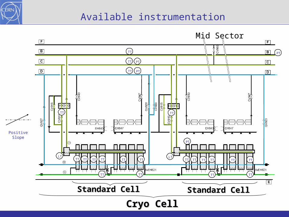
Available instrumentation
Cryo CellCryo CellStandard CellStandard CellStandard CellStandard Cell
LTTT TT TT TT TT TT TT TT TT TT TT TT
PT
TT TT
LT
TT PT
TT PT
TT
TTTT TT TT
Positive Slope
PT
Mid Sector
21Training LHC Powering Luigi Serio
Documentation / informations
LHC Design Report – Chapter 11 - Cryogenics
LHC-Q-ES-0004 (EDMS 710799): The circuit of the LHC cryogenic system
LHC-Q-ES-0003 (EDMS 710797): Functional analysis of the LHC cryogenic system process
http://lhc-cfawg.web.cern.ch/lhc-cfawg/
http://hcc.web.cern.ch/hcc/cryogenics/cryo_systems.php
http://hcc.web.cern.ch/hcc/cryogenics/cryo_magnets.php
http://hcc.web.cern.ch/hcc/cryogenics/cryo_dfbs.php