Embed Size (px)
Citation preview

Traffic Control Manualfor Work onRoadwaysREVISED AND CONSOLIDATED, 1999
Engineering Branch
Ministry of Transportationand Highways
Traffic Control Manualfor Work onRoadwaysREVISED AND CONSOLIDATED, 1999
Engineering Branch
Ministry of Transportationand Highways
Pursuant to the Occupational Health & SafetyRegulation 296/97, traffic control proceduresfor all public roads in British Columbia mustconform to the principles and applications asdescribed in this manual.
Your comments on this Manual may be directed to:
Senior Traffic EngineerMinistry of Transportation and Highways
Highway Engineering BranchP.O. Box 9850 STN PROV GOVT
Victoria BC V8W 9T5Fax: 250.356.7798
Both the Office and Field Edition of this manual arepublished by the British Columbia Ministry of
Transportation and Highways.
Copies of these Manuals may be purchased from:
MoTH Publication OrdersP.O. Box 9850 STN PROV GOVT
Victoria BC V8W 9T5
Telephone: 250.387.5512Fax: 250.356.5310
Advance payment required
Additional publication information is available on theMinistry of Transportation and Highways Website:
www.th.gov.bc.ca/bchighways/publications/pubcat.htm
Canadian Cataloguing in Publication Data
Main entry under title:Traffic control manual for work on roadways. -- Rev.
and consolidated, 1999
Previously published 1995.ISBN 0-7726-4095-5
1. Roads - British Columbia - Maintenance and repair - Handbooks,manuals, etc. 2. Traffic signs and signals - British Columbia -Handbooks, manuals, etc. I. British Columbia. Highway EngineeringBranch. Traffic Engineering Section.
TE220.T73 1999 625.7'6 C99-960423-6
ACKNOWLEDGMENTS
ACKNOWLEDGMENTSThis edition of THE TRAFFIC CONTROL MANUAL FOR WORK ON
ROADWAYS was developed by a Committee for Traffic Control onConstruction and Maintenance Projects which was organized by theBritish Columbia Ministry of Transportation and Highways (HighwayOperations Department).
The principal purpose of the Committee was to review and updatecurrent traffic control standards on all types of projects. The reviewfocused on activities involving short duration, long duration, andfreeway conditions. The duties, responsibilities, and certification offlagpersons was also reviewed by a separate committee. The trafficcontrol standards are organized in a way that non-Ministryorganizations such as utility companies and municipalities, can readilyuse them.
Comments and suggestions from members of the Committee weregreatly appreciated.
British Columbia Ministry of Transportation and Highways
Lorne Holowachuk, Director, Highway Safety (Chairman)
Neil Vickers, Traffic Research Officer, Highway Engineering Branch
Dave Grant, Manager, Health and Safety, Personnel Services Branch
Stu Maynes, Senior Traffic Operations Engineer – South Coast Region
Ric Meidinger, Regional Manager, Operations– Thompson-Okanagan Region
Errol Redman, District Highways Manager – Fort George District
Richie Harold, District Highways Manager – South Island District
Dennis Dodsworth, Project Manager – Vancouver Island Region
Dick Callaghan, Manager, Research and Policy– Sealcoating Operation – Okanagan-Shuswap District
British Columbia Hydro
Keith Langen, Vehicle Safety Officer
British Columbia Telephone
Ron Coppendale, Construction Specialist
British Columbia Road Builders Association
Rod Fru, Director, Main Road Contracting
Workers’ Compensation Board
Gerry Walker, Occupational Safety Officer
The City of Vancouver
Don Henderson, Traffic Management Engineer
British Columbia Public Works Association
Fred Peters, Deputy Director, EngineeringThe Corporation of the Township of Langley
PSB 03/95 3
ACKNOWLEDGMENTS
Acknowledgments continued…
The Corporation of the Township of Richmond
Barry King, Works Yard Operations
Construction Labourers’ Training Plan
Bob Anson, Administrator
Consultant
Arnold Stewart
Editing/Printing
Beverly van Druten, Graphics Technician,Planning Services Branch Contractor
4 1926 01/99
GENERAL INSTRUCTIONS
HOW TO USE THIS MANUALThe Decimal Indexing System
The Traffic Control Manual for Work on Roadways (Office Edition)abbreviated to T.C.Manual (O.E.) consists of five chapters. Eachchapter is divided into sections and, where necessary, intosubsections. Sections and subsections are identified by a decimalnumbering system; for example the notation 1.4.2 refers to Chapter 1(General Instructions), Section 1.4 (Traffic Control [Work] Zones),Subsection 1.4.2 (Transition Area). These numbers should not beconfused with the Sign Numbers which are used to identify individualsigns and for sign ordering.
Each section or subsection deals with one subject (or a particularaspect of that subject) and as individual pages throughout the Manualare not numbered, location of any subject within the text dependsentirely on the decimal indexing system and the numerical progressionthrough each chapter.
Revisions and AdditionsFrom time to time it may be necessary to add new sections and
subsections or to revise some of the existing ones. By using a decimalindexing system and excluding page numbers, it will be possible toinsert additional material and still maintain numerical continuity.
It is important that new or revised pages be placed in the Manual assoon as received so that they do not become lost. Out of date pagesshould be removed and discarded at the same time to ensure theManual is up to date. Each side of each page has a publication date atthe bottom corner. Subsequent pages will be marked similarly with thedate of issue. Insertion of new or revised pages should be recorded onthe second sheet following the inside title page.
AbbreviationsThe following abbreviations have been used in the text:
Sign Group Reference LettersC = Construction and Maintenance R = RegulatoryTW = Temporary Warning W = Warning
Sign ShapesDiam. = Diamond Oct. = Octagonal Rect. = RectangularSq. = Square Tri. = Triangular Par. = Parallelogram
Sign ColoursB = Black G = Green Or. = OrangeR = Red W = White Y = YellowBl. = Blue
PSB 03/95 5 How to Use This Manual
GENERAL INSTRUCTIONS
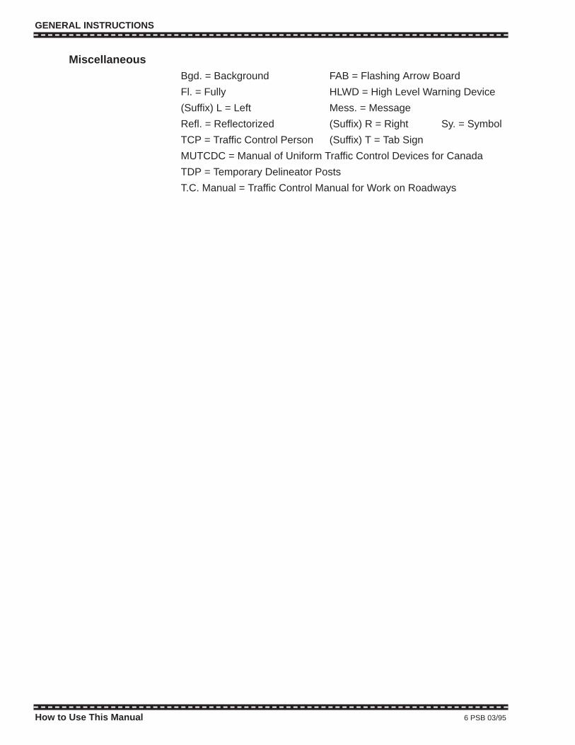
MiscellaneousBgd. = Background FAB = Flashing Arrow Board
Fl. = Fully HLWD = High Level Warning Device
(Suffix) L = Left Mess. = Message
Refl. = Reflectorized (Suffix) R = Right Sy. = Symbol
TCP = Traffic Control Person (Suffix) T = Tab Sign
MUTCDC = Manual of Uniform Traffic Control Devices for Canada
TDP = Temporary Delineator Posts
T.C. Manual = Traffic Control Manual for Work on Roadways
How to Use This Manual 6 PSB 03/95
GENERAL INSTRUCTIONS
MiscellaneousBgd. = Background FAB = Flashing Arrow Board
Fl. = Fully HLWD = High Level Warning Device
(Suffix) L = Left Mess. = Message
Refl. = Reflectorized (Suffix) R = Right Sy. = Symbol
TCP = Traffic Control Person (Suffix) T = Tab Sign
MUTCDC = Manual of Uniform Traffic Control Devices for Canada
TDP = Temporary Delineator Posts
T.C. Manual = Traffic Control Manual for Work on Roadways
How to Use This Manual 6 PSB 03/95

TABLE OF CONTENTS
TRAFFIC CONTROL MANUALFOR WORK ON ROADWAYS (OFFICE EDITION)
(Abbreviated to T.C. Manual)
TABLE OF CONTENTS
CHAPTER 1 - GENERAL INSTRUCTIONS
1.1 GENERAL
1.1.1 Fundamental Principles1.1.2 Definitions1.1.3 Driver Information Needs in Work Zones1.1.4 Training1.1.5 Summary
1.2 APPLICATION OF TRAFFIC CONTROL
1.2.1 Authority1.2.2 Jurisdiction1.2.3 Responsibility
1.2.3.1 Management1.2.3.2 Crew Supervisors
1.2.4 Traffic Control Plan1.2.5 Engineering Study Required for Complex Situations1.2.6 Application of Standards
1.3 TRAFFIC CONTROL DEVICES
1.3.1 Function1.3.2 Requirements in Work Zones
1.4 TRAFFIC CONTROL (WORK) ZONES
Figure 1.4 – Elements of a Traffic Control (Work) Zone1.4.1 Advance Warning Area1.4.2 Transition Area (And Tapers)1.4.3 Buffer Space1.4.4 Work Area1.4.5 Termination Area1.4.6 Lower Speed Zones in Work Areas
1.4.6.1 Construction Speed Zones1.4.6.2 Temporary Speed Zones
1.5 INSTALLATION, MAINTENANCE, AND INSPECTION OF TRAFFIC CONTROL
1.5.1 Installation and Removal of Devices1.5.2 Inspection and Maintenance of Traffic Control1.5.3 Documentation of Traffic Control1.5.4 Potential Traffic Accident Litigation
PSB 03/95 7 Table of Contents
TABLE OF CONTENTS
TRAFFIC CONTROL MANUALFOR WORK ON ROADWAYS (OFFICE EDITION)
(Abbreviated to T.C. Manual)
TABLE OF CONTENTS
CHAPTER 1 - GENERAL INSTRUCTIONS
1.1 GENERAL
1.1.1 Fundamental Principles1.1.2 Definitions1.1.3 Driver Information Needs in Work Zones1.1.4 Training1.1.5 Summary
1.2 APPLICATION OF TRAFFIC CONTROL
1.2.1 Authority1.2.2 Jurisdiction1.2.3 Responsibility
1.2.3.1 Management1.2.3.2 Crew Supervisors
1.2.4 Traffic Control Plan1.2.5 Engineering Study Required for Complex Situations1.2.6 Application of Standards
1.3 TRAFFIC CONTROL DEVICES
1.3.1 Function1.3.2 Requirements in Work Zones
1.4 TRAFFIC CONTROL (WORK) ZONES
Figure 1.4 – Elements of a Traffic Control (Work) Zone1.4.1 Advance Warning Area1.4.2 Transition Area (And Tapers)1.4.3 Buffer Space1.4.4 Work Area1.4.5 Termination Area1.4.6 Lower Speed Zones in Work Areas
1.4.6.1 Construction Speed Zones1.4.6.2 Temporary Speed Zones
1.5 INSTALLATION, MAINTENANCE, AND INSPECTION OF TRAFFIC CONTROL
1.5.1 Installation and Removal of Devices1.5.2 Inspection and Maintenance of Traffic Control1.5.3 Documentation of Traffic Control1.5.4 Potential Traffic Accident Litigation
PSB 03/95 7 Table of Contents

TABLE OF CONTENTS
CHAPTER 2 - TRAFFIC CONTROL DEVICES2.1 TRAFFIC SIGNS
2.1.1 GeneralFigure 2.1.1 – Typical Sign Installations
Showing Heights and Lateral Clearances2.1.2 Sign Dimensions2.1.3 Sign Illustrations at a Glance
2.1.3.1 Construction and Maintenance (C)2.1.3.2 Temporary Warning (TW)2.1.3.3 Regulatory (R)
2.1.4 List of Construction & Maintenance (C) Signs2.1.5 Warrants for Individual (C) Signs2.1.6 List of Temporary Warning (TW) Signs2.1.7 Warrants for Individual (TW) Signs2.1.8 List of Regulatory (R) Signs2.1.9 Warrants for Individual (R) Signs
2.2 OTHER DEVICES2.2.1 Temporary Pavement Markings2.2.2 Channelizing Devices – General
2.2.2.1 Channelizing Devices at a Glance2.2.2.2 Flexible Drums2.2.2.3 Temporary Delineator Posts (TDPs)2.2.2.4 Traffic Cones and Tubular Markers2.2.2.5 Barricades2.2.2.6 Concrete Barriers
2.2.3 Lighting Devices2.2.3.1 Yellow Warning Lights2.2.3.2 Flashing Vehicle Lights2.2.3.3 Flashing Arrow Boards (FABs)2.2.3.4 Overhead Flashing Beacons2.2.3.5 Floodlights
2.2.4 Shadow Vehicles2.2.5 Buffer Vehicles2.2.6 Portable Sign Supports2.2.7 High Level Warning Devices (HLWDs)2.2.8 Temporary Lane Control Signals
2.2.8.1 General2.2.8.2 Timing for (Temporary) One-way Signals
2.2.9 Flags for Use with HLWDs and Temporary Sign Supports
2.3 TRAFFIC CONTROL PERSONS (TCPs)2.3.1 General2.3.2 Responsibility2.3.3 Qualifications2.3.4 Training2.3.5 Equipment2.3.6 Positioning2.3.7 TCP Signals to Stop and Slow Traffic2.3.8 Location of TCPs
Table of Contents 8 1926 01/99
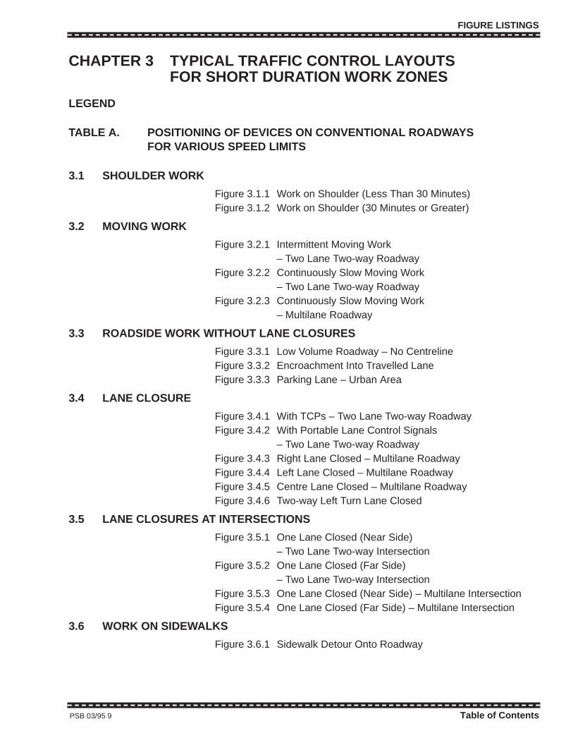
FIGURE LISTINGS
CHAPTER 3 TYPICAL TRAFFIC CONTROL LAYOUTSFOR SHORT DURATION WORK ZONES
LEGEND
TABLE A. POSITIONING OF DEVICES ON CONVENTIONAL ROADWAYSFOR VARIOUS SPEED LIMITS
3.1 SHOULDER WORK
Figure 3.1.1 Work on Shoulder (Less Than 30 Minutes)Figure 3.1.2 Work on Shoulder (30 Minutes or Greater)
3.2 MOVING WORK
Figure 3.2.1 Intermittent Moving Work– Two Lane Two-way Roadway
Figure 3.2.2 Continuously Slow Moving Work– Two Lane Two-way Roadway
Figure 3.2.3 Continuously Slow Moving Work– Multilane Roadway
3.3 ROADSIDE WORK WITHOUT LANE CLOSURES
Figure 3.3.1 Low Volume Roadway – No CentrelineFigure 3.3.2 Encroachment Into Travelled LaneFigure 3.3.3 Parking Lane – Urban Area
3.4 LANE CLOSURE
Figure 3.4.1 With TCPs – Two Lane Two-way RoadwayFigure 3.4.2 With Portable Lane Control Signals
– Two Lane Two-way RoadwayFigure 3.4.3 Right Lane Closed – Multilane RoadwayFigure 3.4.4 Left Lane Closed – Multilane Roadway Figure 3.4.5 Centre Lane Closed – Multilane RoadwayFigure 3.4.6 Two-way Left Turn Lane Closed
3.5 LANE CLOSURES AT INTERSECTIONS
Figure 3.5.1 One Lane Closed (Near Side)– Two Lane Two-way Intersection
Figure 3.5.2 One Lane Closed (Far Side)– Two Lane Two-way Intersection
Figure 3.5.3 One Lane Closed (Near Side) – Multilane IntersectionFigure 3.5.4 One Lane Closed (Far Side) – Multilane Intersection
3.6 WORK ON SIDEWALKS
Figure 3.6.1 Sidewalk Detour Onto Roadway
PSB 03/95 9 Table of Contents
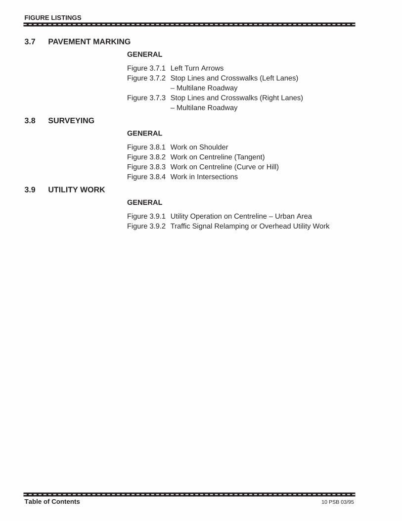
FIGURE LISTINGS
3.7 PAVEMENT MARKING
GENERAL
Figure 3.7.1 Left Turn ArrowsFigure 3.7.2 Stop Lines and Crosswalks (Left Lanes)
– Multilane RoadwayFigure 3.7.3 Stop Lines and Crosswalks (Right Lanes)
– Multilane Roadway
3.8 SURVEYING
GENERAL
Figure 3.8.1 Work on ShoulderFigure 3.8.2 Work on Centreline (Tangent)Figure 3.8.3 Work on Centreline (Curve or Hill)Figure 3.8.4 Work in Intersections
3.9 UTILITY WORK
GENERAL
Figure 3.9.1 Utility Operation on Centreline – Urban AreaFigure 3.9.2 Traffic Signal Relamping or Overhead Utility Work
Table of Contents 10 PSB 03/95

FIGURE LISTINGS
CHAPTER 4 TYPICAL TRAFFIC CONTROL LAYOUTSFOR LONG DURATION WORK ZONES
LEGEND
TABLE A. POSITIONING OF DEVICES ON CONVENTIONAL ROADWAYSFOR VARIOUS SPEED LIMITS
4.1 CONSTRUCTION SPEED ZONES
Figure 4.1.1 Typical Construction Speed Zone Signing
4.2 SHOULDER AND ROADSIDE WORK
Figure 4.2.1 Work on Shoulder Figure 4.2.2 Work on Low Volume Roadway – No Centreline
4.3 LANE CLOSURES BETWEEN INTERSECTIONS
Figure 4.3.1 With TCPs – Two Lane Two-way RoadwayFigure 4.3.2 Right Lane Closed – Multilane RoadwayFigure 4.3.3 Left Lane Closed – Multilane RoadwayFigure 4.3.4 Median Crossover – Multilane RoadwayFigure 4.3.5 Two-way Left Turn Lane ClosedFigure 4.3.6 One Lane Bridge or Roadway
4.4 LANE CLOSURES AT INTERSECTIONS
Figure 4.4.1 One Lane Closed (Near Side) – Multilane IntersectionFigure 4.4.2 One Lane Closed (Far Side) – Multilane IntersectionFigure 4.4.3 One Lane Closed – Multilane IntersectionFigure 4.4.4 Two Lanes Closed (Near Side) – Multilane Intersection
4.5 DETOURS
Figure 4.5.1 Roadside Diversion – Two Lane Two-way RoadwayFigure 4.5.2 One Lane Closed (Near Side)
– Two Lane Two-way IntersectionFigure 4.5.3 One Lane Closed (Far Side)
– Two Lane Two-way Intersection
4.6 SIDEWALKS
Figure 4.6.1 Sidewalk Detour – Multilane RoadwayFigure 4.6.2 Sidewalk Detour – Multilane Intersection
PSB 03/95 11 Table of Contents

FIGURE LISTINGS
CHAPTER 5 TYPICAL TRAFFIC CONTROL LAYOUTSFOR FREEWAY WORK ZONES
LEGEND
TABLE B. POSITIONING OF DEVICES ON FREEWAYS
5.1 ADVANCE WARNING AREA SIGNS
Figure 5.1.1 Advance Warning Area – Longer Term Work
5.2 Not assigned
5.3 SHOULDER WORK
Figure 5.3.1 Work on Shoulder – Moving and Stationary
5.4 SLOW MOVING WORK – OPEN LANE
Figure 5.4.1 Continuous Slow Moving WorkWithout Lane Closure
5.5 STATIONARY AND INTERMITTENT MOVING WORK – LANE CLOSED
Figure 5.5.1 Stationary and Intermittent Moving WorkWith Lane Closure
5.6 MEDIAN CROSS OVER
Figure 5.6.1(a) Near Side SigningFigure 5.6.1(b) Far Side Signing
5.7 TWO LANES CLOSED
Figure 5.7.1 Two Lanes Closed on Three Lane Roadway
5.8 LANE CLOSURE AT EXIT RAMP
Figure 5.8.1 Lane Closure at Open Exit Ramp
5.9 LANE CLOSURE AT ENTRANCE RAMP
Figure 5.9.1 Lane Closure at Open Entrance Ramp
5.10 CLOSURE OF EXIT RAMP
Figure 5.10.1 Temporary Closure of Exit Ramp
Table of Contents 12 PSB 03/95
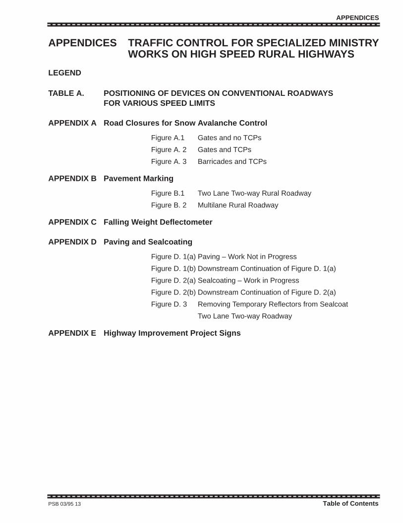
APPENDICES
APPENDICES TRAFFIC CONTROL FOR SPECIALIZED MINISTRYWORKS ON HIGH SPEED RURAL HIGHWAYS
LEGEND
TABLE A. POSITIONING OF DEVICES ON CONVENTIONAL ROADWAYSFOR VARIOUS SPEED LIMITS
APPENDIX A Road Closures for Snow Avalanche Control
Figure A.1 Gates and no TCPs
Figure A. 2 Gates and TCPs
Figure A. 3 Barricades and TCPs
APPENDIX B Pavement Marking
Figure B.1 Two Lane Two-way Rural Roadway
Figure B. 2 Multilane Rural Roadway
APPENDIX C Falling Weight Deflectometer
APPENDIX D Paving and Sealcoating
Figure D. 1(a) Paving – Work Not in Progress
Figure D. 1(b) Downstream Continuation of Figure D. 1(a)
Figure D. 2(a) Sealcoating – Work in Progress
Figure D. 2(b) Downstream Continuation of Figure D. 2(a)
Figure D. 3 Removing Temporary Reflectors from Sealcoat
Two Lane Two-way Roadway
APPENDIX E Highway Improvement Project Signs
PSB 03/95 13 Table of Contents

Table of Contents 14 PSB 03/95 Table of Contents 14 PSB 03/95

TABLE OFCONTENTS
TABLE OFCONTENTS

CHAPTER 1
GENERALINSTRUCTIONS
CHAPTER 1
GENERALINSTRUCTIONS
SECTION 2. 1
TRAFFIC SIGNS
SECTION 2. 1
TRAFFIC SIGNS
SECTION 2.2
OTHER DEVICES
SECTION 2.2
OTHER DEVICES
SECTION 2.3
TRAFFIC CONTROLPERSONS
SECTION 2.3
TRAFFIC CONTROLPERSONS

CHAPTER 3
TYPICAL TRAFFIC CONTROLLAYOUTS
FOR SHORT DURATIONWORK ZONES
CHAPTER 3
TYPICAL TRAFFIC CONTROLLAYOUTS
FOR SHORT DURATIONWORK ZONES
CHAPTER 4
TYPICAL TRAFFIC CONTROLLAYOUTS
FOR LONG DURATIONWORK ZONES
CHAPTER 4
TYPICAL TRAFFIC CONTROLLAYOUTS
FOR LONG DURATIONWORK ZONES

CHAPTER 5
TYPICAL TRAFFIC CONTROLLAYOUTS
FOR FREEWAYS
CHAPTER 5
TYPICAL TRAFFIC CONTROLLAYOUTS
FOR FREEWAYS
APPENDICES APPENDICES

GENERAL INSTRUCTIONS
CHAPTER 1GENERAL INSTRUCTIONS
1.1 GENERALTraffic control is required when traffic must be moved through or
around highway or street construction, maintenance operations orutility work on or adjacent to a roadway. The traffic control describedand illustrated herein is generally the minimum required. No onestandard sequence of signs or other control devices can be set up asan inflexible arrangement for all conditions and locations, due to thevariety of conditions encountered. It should also be recognized thatwhile the Traffic Control (T.C.) Manual for Work on Roadways containsmandatory language such as “shall” there may be circumstanceswhere strict compliance with such requirements is not reasonable andit will be necessary to deviate from the requirements.
Throughout this Manual, the term “work zone” , as also defined inSubsection 1.1.2, means an area in which construction, maintenanceor utility activities take place, on or adjacent to a roadway, to the extentthat the passage of public traffic may be influenced. Where cyclistsand/or pedestrians are likely to be present in work zones, dueconsideration must also be given to their safety requirements.
This T.C. Manual sets forth basic principles and prescribesstandards for the design, application, installation and maintenance ofthe various types of traffic control through work zones. These includesigns, signals, lighting devices, markings, barricades, channelization,and hand signaling devices. Minimum standards of application areprescribed for typical situations and for methods of controlling trafficthrough work zones. A number of typical situations are illustrated toshow the recommended application of standard protective devices forpre-planned, scheduled, work on roads and streets in British Columbia.
It is understood that in emergency situations it may not be possibleto meet these minimum standards.
1.1.1 FUNDAMENTAL PRINCIPLESAll traffic control devices used in work zones should closely conform
to the applicable specifications of this T.C. Manual.
Work zones can present motorists, cyclists and pedestrians withunexpected or unusual situations as far as traffic operations areconcerned. Because of this, special care should be taken in applyingtraffic control techniques.
Principles and procedures which experience has shown to enhancethe safety of road users and workers in the vicinity of work areasinclude the following:
.1 Traffic safety in construction zones is an integral and high priorityelement of every project from planning through design andconstruction. Similarly, maintenance and utility work should beplanned and conducted with the safety of road users and workerskept in mind at all times.
PSB 03/95 15 1.1 – 1.1.1

GENERAL INSTRUCTIONS
1.1.1 FUNDAMENTAL PRINCIPLES (continued)
a. The basic safety principles governing the use of permanenttraffic control on undisturbed roadways and roadsides shouldalso govern the design of traffic control in work zones. The goalshould be to route traffic through such zones with traffic controldevices as nearly as possible comparable to those for normalsituations.
b. A traffic control plan in detail appropriate to the complexity of theproject, should be prepared and understood by all responsibleparties before work begins. Any changes in the agreed trafficcontrol plan should be pre-approved by the road authority beforeimplementation.
.2 Traffic movement should be inhibited as little as possible.
a. The traffic control plans for work zones should be designed onthe assumption that motorists will only reduce speed if theyclearly perceive a need to do so. Reduced speed zones shouldonly be used where a clearly demonstrated need exists.
b. Any changes in traffic pattern, such as lane narrowings, droppedlanes or other main roadway transitions requiring rapidmaneuvers, should be avoided.
c. Where emergency vehicles will pass through a work zone it maybe necessary to make special provision for such vehiclesespecially on high speed or high volume roadways.
d. Construction time should be minimized to reduce exposure topotential hazards.
.3 Motorists should be guided in a clear and positive manner whileapproaching and traversing work zones.
a. Adequate warning, delineation and channelization by means ofproper pavement marking, signing and use of other deviceswhich are effective under varying conditions of light and weathershould be provided to assure motorists of positive guidance inadvance of and through work zones.
b. Inappropriate pavement markings should be removed for longduration work to eliminate any misleading cues to drivers in allconditions of light and weather. On short term maintenanceprojects, however, it may be determined that such removal ismore hazardous than leaving the existing markings in place. Ifso, special attention must be paid to providing additionalguidance by other traffic control measures.
c. Traffic control persons (TCPs), when used, can provide positiveguidance to motorists traversing work zones. TCPs must beemployed when all other methods of controlling traffic areconsidered inadequate to warn, direct and regulate drivers.
.4 To ensure acceptable levels of operation, routine inspection oftraffic control devices should be performed.
1.1.1 16 PSB 03/95
GENERAL INSTRUCTIONS
1.1.1 FUNDAMENTAL PRINCIPLES (continued)
a. Individuals who are trained in the principles of traffic controlshould be assigned responsibility for safety at work sites. Themost important duty of these individuals is to ensure that alltraffic control devices are in conformity with the traffic controlplan and are effective in providing safe conditions for motorists,pedestrians, cyclists and workers.
b. From time to time,modification of traffic controls may be requiredin order to expedite traffic movement and to ensure safety. It isessential that the individual responsible for traffic control alsohas the authority to control the progress of work on the project inits relation to maintaining safe conditions, including the authorityto modify controls or halt work until remedial safety measuresare taken.
c. Work sites should be carefully monitored under varyingconditions of traffic volume, light and weather to ensure thattraffic control measures are operating effectively and that alldevices used are appropriate,clearly visible, clean and in goodrepair.
d. When activity in a work zone ceases, for whatever reason orduration, it is very important that adequate traffic control ismaintained to guide, warn and regulate public traffic through anyhazards or unusual traffic patterns; keeping in mind the mostadverse conditions that could reasonably be expected to occur,prior to the recommencement of work.
e. When warranted, an engineering analysis should be made of allaccidents occurring within work zones. Work zones should bemonitored to identify and analyze traffic accidents or conflicts. Asexamples, skid marks or damaged traffic control devices mayindicate needed changes in the traffic control.
f. Work zone accident records should be analyzed periodically toguide officials in improving work zone operations.
g. When no longer needed, traffic control devices must beremoved or covered.
.5 The maintenance of roadside safety requires constant attentionduring the life of the work zone because of the potential increase inhazards.
a. To accommodate errant and disabled vehicles, it is desirable toprovide an unencumbered roadside recovery area that is aswide as practicable.
b. Channelization of traffic should be accomplished by the use ofpavement markings and signing, flexible posts or drums,delineators, cones, barricades and other lightweight deviceswhich will yield if hit by errant vehicles.
c. Whenever practicable, construction equipment and materialsshould be stored clear of the travelled roadway. If this is notpossible, such obstructions should be clearly marked and thepath around them delineated.
PSB 03/95 17 1.1.1

GENERAL INSTRUCTIONS
1.1.2 DEFINITIONSBuffer Vehicle
A vehicle positioned in advance of an active stationary or movingwork site to protect workers from errant vehicles (such vehicles shalldisplay either a FAB or 360° light and 4-way flashers).
Construction Speed Zone
A lowered legal speed zone, normally through a long duration workzone, as authorized by the road authority.
Continuous Slow Moving Work
Work which is continuously moving such that the use of regulartraffic control procedures is impracticable (e.g., grading, striping,hydroseeding, mowing, brushing, flushing, sweeping, spraying for dustcontrol etc.).
Detour Route
A route which takes traffic off the regular route and, using existing ornewly made temporary roadways, guides traffic around a work zone.The detour route must be clearly identified by appropriate detour signs.(Prior to the closing of a roadway and the opening of a detour, it isdesirable to erect “Closing Notice” signs at strategically selectedlocations at least one week in advance of the actual closing.)
Downstream Direction
The direction towards which traffic flows.
Emergency and Brief Duration Work
Work, generally of an unprogrammed emergency nature, requiringvery little time, usually less than 15 minutes (e.g. unblocking catchbasins, removal of fallen tree limbs, water valve operation, cleanup ofmaterial spills, filling isolated potholes, etc.)
Freeway
A public highway with a continuous nontraversable dividing median,grade separated interchanges and typically with a posted speed limit of80 km/h or greater.
Highway
A roadway or roadways, typically in a higher speed zone, carryinginter-regional vehicular traffic.
Intermittent Moving Work
A maintenance activity which involves a work zone that changesfrequently (e.g. some mowing operations) or involves frequent stopsnot exceeding 30 minutes duration (e.g. temporary patching, grouprelamping of street lights, Benkleman beam testing, crack sealing, etc.)
Long Duration Work
Programmed construction, maintenance and utility activities whichrequire a separate work area for more than one daytime shift. Thusmost work at night should, therefore, be considered long duration.
1.1.2 18 PSB 03/95
GENERAL INSTRUCTIONS
1.1.2 DEFINITIONS (continued)
Low Volume/High Volume Roadway
A low volume roadway is one which carries less than 1,000 vehiclesper day. A high volume roadway thus carries 1,000 or more vehiclesper day. (For a two-way roadway, the applicable volume is the dailytotal carried in both directions.) Traffic volumes can be obtained fromthe local road authority.
Line-type Vehicles
A truck with a large cable spool mounted on the rear of the vehicle,typically used by power and telephone companies when for installingnew power or communications lines.
Ministry
Means the Ministry of Transportation and Highways
Multilane Roadway
A roadway with two or more lanes in at least one direction includingclimbing and passing lanes.
Temporary Lane Control Signal
An electrical device, with one traffic signal head per direction, whichmay be used as an alternative to TCPs in short duration work forcontrolling a temporary one-way traffic section on a normally two-wayroadway.
Roadside Diversion
A deviation from the normal roadway where work closes a section ofa road and a short detour, usually within the right-of-way, is required tobypass the work area.
Roadway
The portion of a street or highway that is ordinarily used for vehiculartraffic, but, does not include the shoulder; and where a highwayincludes two separate roadways, the term “roadway” refers to any oneroadway separately and not to both of them collectively.
Shadow Vehicle
A vehicle used mainly in continuous slow moving operations, as amobile advance warning and sign support. (Such a vehicle willnormally travel as far over on the shoulder as possible, i.e. shadowvehicles do not block travelled lanes as do buffer vehicles.)
Short Duration Work
Programmed work which requires a separate work area for not morethan one daytime shift.
Street
A public road used for the movement of vehicles in a local area.
Tangent Distance
The distance between the end of one taper and the beginning of thenext taper for the same direction of travel.
1926 01/99 19 1.1.2

GENERAL INSTRUCTIONS
1.1.2 DEFINITIONS (continued)
Taper and Taper Length (Lane or Shoulder Closure)
The gradual narrowing of a lane or shoulder using successive conesor markers to safely guide drivers into the next lane. Taper length is thedistance along a section of roadway required to achieve full closure ofone lane or shoulder.
Temporary Speed Zone
A lowered legal speed zone imposed at the discretion of asupervisor with C-1 or C-2 signs in a short duration work zone.
Temporary Traffic Control Signal
A signal used (a) to control traffic at an intersection with a temporaryroadway, truck access route and pedestrian crossing, etc., or (b) toassign right-of-way on long duration work (such as bridge resurfacing),in place of TCPs or a portable lane control signal, where traffic movingin both directions must use a single lane on a normally two-wayroadway. (The design specifications for temporary signals require priorapproval by the appropriate road authority).
Traffic Control Person (TCP)
A person trained to conduct traffic through a work zone; having inmind both the safety of workers and public traffic.
Two Lane Two-Way Roadway
A two-way roadway with one through lane per direction.
Upstream Direction
The direction from which traffic flows.
Work Zone
An area in which surveying, construction, maintenance or utilityactivities take place, on or adjacent to a roadway, to the extent that thepassage of public traffic may be influenced.
1.1.3 DRIVER INFORMATION NEEDS IN WORK ZONESThe usefulness of traffic control devices intended to assist motorists
in guidance and navigation tasks depends on whether the devicessatisfy a driver’s need for information. Both the message content andthe placement of the traffic control devices must be carefullyconsidered.
Inappropriate or unclear messages and/or incorrect placement ofsigns, markings, and other traffic control devices can mislead andconfuse the motorist.
In work zones there are usually three types of traffic control devicemessage content. These are the warning of potential hazards, postingof applicable regulations such as maximum speeds, and thedelineation of traffic paths.
Positive guidance principles should be considered when determiningwhich traffic control devices will be used and where they will belocated.
1.1.2 – 1.1.3 20 1926 01/99

GENERAL INSTRUCTIONS
1.1.3 DRIVER INFORMATION NEEDS IN WORK ZONES (continued)
The more serious instances of driver misunderstanding and non-compliance result from:
• providing contradictory or misleading information;• presenting a sign with inaccurate distance information; and• using nonstandard messages or using inappropriate standard
signs.
1.1.4 TRAININGPersonnel whose actions affect work zone safety should receive
training appropriate to the job decisions those individuals are requiredto make. Only those individuals who are qualified in safe traffic controlpractices and have a basic understanding of the principles establishedby applicable standards and Regulations, should supervise theselection, placement and maintenance of traffic control devices in workzones.
1.1.5 SUMMARYThe following list of items can be used for the general guidance ofthose involved with work zone traffic control activities:
• Retain the motorist’s respect and the agency’s credibility by notproviding misinformation.
• When work is not in progress or devices are no longer needed,remove or cover them.
• Do not assume that drivers, cyclists and pedestrians will see orrecognize the workers or hazards in a work zone. Remember thatthe visibility of hazards/workers can be greatly diminished indarkness and/or poor weather conditions.
• Maintain the controls as if every driver were approaching the areafor the first time and in less than ideal conditions.
• The philosophy of good work zone traffic control must beunderstood by field personnel so they can perform their work witha minimum of exposure to traffic, be on the lookout for problemsand be capable of replacing or reporting any damaged or missingdevices.
PSB 03/95 21 1.1.3 – 1.1.5

APPLICATIONS
1.2 APPLICATION OF TRAFFIC CONTROL1.2.1 AUTHORITY
The authority for the placement of traffic control devices on allstreets and highways in British Columbia is contained in variousProvincial acts and municipal bylaws.
No work should commence on a public roadway without firstobtaining a work permit providing approval by the road authorityconcerned. Road authorities generally grant continuing permits forspecific routine and emergency operations such as those conductedby utility companies.
1.2.2 JURISDICTIONJurisdiction for traffic control is as follows:
• for municipal streets, the municipality having jurisdiction over thearea;
• for Provincial highways, and roads in unorganized areas, theMinistry of Transportation and Highways
Workers Compensation Board Industrial Health and SafetyRegulations require that adequate precautions are taken to protectworkers from hazards to which they may be exposed. The regulationsrequire protective clothing, equipment, devices and work proceduresthat protect workers from hazards caused by public and constructiontraffic.
1.2.3 RESPONSIBILITYIt is important that the road authorities having jurisdiction requireproper traffic control, that responsibility be clearly assigned, adequatetraining of personnel be provided, and that there be adherence to theprinciples and applications provided in this T.C. Manual.
1.2.3.1 Responsibility of ManagementIt is the responsibility of management to ensure that all crew andsupervisors are thoroughly trained and familiar with applicable safeworking practices, and that they take immediate and decisive actionwhen safe and approved work methods are not followed.
1.2.3.2 Responsibility of the Crew SupervisorsIt is the responsibility of the crew supervisors to ensure that eachmember of the crew wears the required personal safety clothing whenworking on or crossing the highway. It is also the crew supervisor'sresponsibility to ensure that the work area is protected by the use ofthe various signs, cones, flashing lights, TCPs, etc., generally asoutlined in this Manual.
1.2 – 1.2.3.2 22 PSB 03/95
APPLICATIONS
1.2.4 TRAFFIC CONTROL PLANPlanning for traffic control in work zones is very important. Traffic
control plans should be formulated by qualified personnel and theplans should be reviewed as work progresses. The principles of pre-planning and review should always apply, regardless of the projectsize.
The traffic control plan may range in scope from a reference tostandard plans, a section of this Manual, or to a very detailed designsolely for a specific project. The needed detail in the plan depends onthe complexity of the work and on the conflicts between traffic and thework. The plan should include such items as provision for adequateseparation of public traffic and work areas, the limitation of workperiods (where necessary) and for lane closures based on carefulconsideration of anticipated traffic volumes and minimum exposure ofworkers.
The plan for traffic control should also include, but not be limited to,such items as signing, application and/or removal of pavementmarkings, roadway lighting, methods and devices for delineation,channelization and placement and maintenance of all devices.
1.2.5 ENGINEERING STUDY REQUIRED FOR COMPLEX SITUATIONSThe decision to use a particular device or devices at a particular
location should be made on the basis of a study of the location. Thus,while this Manual provides standards for design and application oftraffic control devices, it is not a substitute for engineering judgment.It is the intent that the provisions of this Manual be minimumrecommended standards for traffic control. They are, however,recommendations but not legal requirements.
For complex projects, supervisors are required to exercise judgmentin the selection of traffic control devices, just as they do in designingthe roads and streets which the devices complement. Jurisdictions withresponsibility for traffic control, that do not have qualified engineeringstaff, should seek assistance from a qualified traffic engineeringconsultant.
1.2.6 APPLICATION OF STANDARDSThe provisions for vehicular, pedestrian, cyclist and worker
protection established herein are for application by:
1. The Provincial and Municipal road authorities in British Columbiaand their contractors.
2. Public utilities and their contractors and others who have approvalto work on or adjacent to public roadways.
The standards in this Manual should be adopted by all roadauthorities and utility companies concerned with street and highwaywork, and should be given effect by official instructions to employeesand by incorporation into the specifications for all roadwork contracts.
PSB 03/95 23 1.2.4 – 1.2.6

APPLICATIONS
1.2.6 APPLICATION OF STANDARDS (continued)
The general principles outlined in this Manual are applicable to bothrural and urban areas. Since it is not practical to prescribe detailedstandards of application for all the situations that may arise, minimumstandards are presented here for the most common situations. It isemphasized that these are minimum desirable standards for normalsituations and that additional protection must be provided when specialcomplexities and hazards exist. The protection prescribed for eachsituation is based on the speed and volume of traffic, the duration ofoperations and the public exposure to hazards.
Traffic conditions on urban streets are characterized by lowerspeeds, a wide range of traffic volumes, limited maneuvering space,frequent turns and cross movements, significant pedestrian movementand other obstructions. Construction, maintenance and utilityoperations are more numerous and varied, including such diverseactivities as pavement cuts for utility work, pavement patching andsurfacing, pavement marking renewal and encroachments by adjacentbuilding construction. Work on high volume, urban streets should berestricted to off peak hours to minimize conflicts with traffic.
On rural highways traffic conditions are also characterized by a widerange of volumes and higher speeds but less interference frompedestrians, turns and encroachments.
Freeways and other multilane highways present traffic controlproblems requiring special attention. Both high speeds and highvolumes may be anticipated. Any work carried out in daylight mayhave to be limited to relatively short periods when volumes in the off-peak direction are sufficiently light.
The difficulties associated with the completion of work on lanescarrying high volumes of traffic may make it necessary, in someinstances, to schedule construction and/or maintenance operations atnight. While night scheduling avoids peak flows, the problemsassociated with the need for greater visibility of work site delineationand warning devices are increased.
For situations not specifically illustrated in this Manual, traffic controlprocedures must be established by appropriate modification of existingexamples and/or application of the general control principles set outherein.
1.2.6 24 PSB 03/95
TRAFFIC CONTROL DEVICES
1.3 TRAFFIC CONTROL DEVICES1.3.1 FUNCTION
The function of traffic control devices is to ensure roadway safety byproviding for the orderly and safe movement of vehicles andpedestrians, throughout the public road system and to provide suchguidance, regulation and warning as needed to ensure the safepassage of all the individual elements of the traffic stream.
For vehicle operators, traffic control devices are provided to assist inthe guidance and navigation tasks required to safely traverse anyfacility open to public travel.
1.3.2 REQUIREMENTS IN WORK ZONESThis Manual sets forth the basic principles and warrants for the
design and use of traffic control devices in work zones. Theseprinciples and warrants appear throughout the text relating to thespecific devices or groups of devices. It is important that principles andwarrants be given primary consideration in the selection andapplication of each device.
The Manual details traffic control device standards for work zoneson all streets and highways open to public travel; regardless of thetype of roadway or the authority having jurisdiction. Where a device isintended only for limited application, or for a specific situation, the textspecifies the restrictions imposed on its use.
To be effective, all traffic control devices must meet five basicrequirements. These are to:
• Fulfill a need.
• Command attention.
• Convey a clear, simple meaning.
• Provide adequate time for a proper response.
• Command respect of road users.
Uniformity of meaning is vital to effective traffic control devices.
Five basic considerations are employed to ensure that theserequirements are met. They are: design, placement, application,maintenance and uniformity.
The placement, size and sign messages should be such thatattention is drawn to them, that they are legible, their meaning is clear,the regulation is reasonable and there is adequate time for response.In situations where messages are required other than those hereinprovided for, the signs should have the same shape, colour,dimensions and illumination or reflectorization as signs of the sameclassification. Symbols, wording and lettering should conform asclosely as possible to signs of the same type.
PSB 03/95 25 1.3 – 1.3.2

TRAFFIC CONTROL DEVICES
1.3.2 REQUIREMENTS IN WORK ZONES (continued)
Consistent application should ensure that appropriate devices areinstalled in a standard fashion to meet the traffic control requirementsat any given location. Furthermore, devices must be placed in auniform and consistent manner to ensure that vehicle operators can beexpected to respond properly to the devices based on their previousexposure to similar traffic control situations.
Maintenance of devices should be to a high standard to ensure thatlegibility is retained, that the devices are visible and that they are onlyin place when needed. Clean, legible and properly mounted devices, ingood condition, command the respect of vehicle operators, cyclists andpedestrians. In addition to physical maintenance, functionalmaintenance is required to adjust needed traffic control devices tocurrent conditions and to remove any which are unnecessary. The factthat a device is in good physical condition should not be a basis forretaining it if the message is inappropriate. Furthermore, carelesslyexecuted functional maintenance can destroy the value of a group ofdevices by throwing them out of balance. For example, replacement ofa sign in a group or series by one that is disproportionately larger orsmaller.
Uniformity in the design of traffic control devices simplifies the taskof the road user because it aids in recognition and understanding. Italso provides economy in manufacture.
Simply stated, uniformity means always treating similar situations inthe same way. The use of uniform traffic control devices does not, initself, constitute uniformity. A standard device used where it is notappropriate is as objectionable as a nonstandard device; in fact, thismay be worse, in that such misuse may result in public disregard forthe device at other locations where it is needed.
The actions required of drivers, cyclists and pedestrians byregulatory devices must be specified by Provincial statute, and/ormunicipal by-law.
1.3.2 26 PSB 03/95
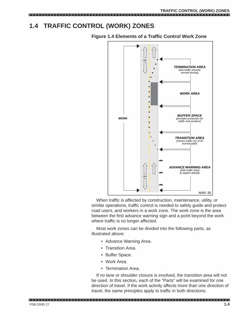
TRAFFIC CONTROL (WORK) ZONES
1.4 TRAFFIC CONTROL (WORK) ZONES
Figure 1.4 Elements of a Traffic Control Work Zone
When traffic is affected by construction, maintenance, utility, orsimilar operations, traffic control is needed to safely guide and protectroad users, and workers in a work zone. The work zone is the areabetween the first advance warning sign and a point beyond the workwhere traffic is no longer affected.
Most work zones can be divided into the following parts, asillustrated above:
• Advance Warning Area.
• Transition Area.
• Buffer Space.
• Work Area.
• Termination Area.
If no lane or shoulder closure is involved, the transition area will notbe used. In this section, each of the “Parts” will be examined for onedirection of travel. If the work activity affects more than one direction oftravel, the same principles apply to traffic in both directions.
PSB 03/95 27 1.4
BUFFER SPACE(provides protection for
traffic and workers)WORK
ADVANCE WARNING AREA(tells traffic whatto expect ahead)
TRANSITION AREA(moves traffic out of its
normal path)
WORK AREA
TERMINATION AREA(lets traffic resume
normal driving)
MAR. 95
OR
OR
TRAFFIC CONTROL (WORK) ZONES
1.4.1 ADVANCE WARNING AREAAn advance warning area is necessary for all traffic control zones
because drivers need to know what to expect ahead. Before reachingthe work area, drivers should have enough time to adjust their drivingpatterns. The advance warning area may vary from a series of signs,starting 2 km in advance of the work area, to a single sign or flashinglights on a vehicle.
Advance warning signs are not needed when the work area,including access to the work area, is entirely off the roadway andshoulder and the work does not interfere with traffic. An advancewarning sign or signs should be used when any problems or conflictswith the flow of traffic might possibly occur.
Length of the Advance Warning Area
The advance warning area, from the first sign to the start of the nextarea, should be long enough to give the motorists adequate time torespond to the conditions.
In Chapters 3, 4 and 5, Tables A and B and the typical sign layoutsindicate recommended sign locations.
1.4.2 TRANSITION AREA (AND TAPERS)When work is performed within one or more travelled lanes, a lane
closure(s) is required. In the transition area, traffic is channelized fromits normal highway lane(s) to another path in order to move trafficaround the work area. The transition area contains the tapers whichare used to close lanes.
The transition area should be made obvious to drivers. The correctpath should be clearly identified with pavement markings and/orchannelizing devices so drivers will not attempt to follow the old path.Where practical, for long duration work zones, existing pavementmarkings should be removed when they conflict with the transition andnew markings should be added. Pavement marking arrows are alsouseful in transition areas.
With moving operations, the transition area moves with the workarea. A shadow vehicle may be used to warn traffic and/or guide it intothe proper lane. Refer to the section 2.2.4, Shadow Vehicles, foradditional guidance.
Tapers
A taper is identified by a series of channelizing devices and possiblypavement markings placed on an angle to the normal travel path tomove traffic out of its normal path.
Four types of tapers used in traffic control zones are:
• Lane closure tapers are those necessary for closing lanes ofmoving traffic on a one-way roadway (sometimes referred to aschannelizing tapers).
1.4.1 – 1.4.2 28 PSB 03/95

TRAFFIC CONTROL (WORK) ZONES
1.4.2 TRANSITION AREAS AND TAPERS (continued)
• Two-way traffic tapers are those needed to control two-way trafficwhere traffic is required to alternately use a single lane when atraffic signal, lane control signal or traffic control persons arepresent.
• Shoulder closure tapers are those needed to close shoulderareas.
• Downstream tapers are those installed to direct traffic back into itsnormal path.
Lane Closure Taper (One-way Roadway)
The length of a taper used to close a lane is determined by thespeed of traffic and the width of the lane to be closed (the lateraldistance that traffic is shifted).The taper lengths shown in line 1a* ofTable A and line 1 of Table B are for normal lane widths. For greaterlane widths use the taper ratios shown on the same lines. If restrictedsight distance is a problem (e.g., a sharp vertical or horizontalcurve), the taper should begin well in advance of the sightrestriction. The beginning of a taper should not be hiddendownstream of curves.
Generally, tapers should be lengthened, not shortened, to increasetheir effectiveness. Traffic should be observed to see if the taper isworking correctly. Frequent use of brakes and evidence of skid marksis an indication that either the taper is too short or the advance warningis inadequate.
Merging of two lanes of traffic into one lane where the combinedvolume exceeds 1,200 to 1,500 vehicles per hour will cause extensivedelays.
Two-Way Traffic Taper (Single lane open)
The two-way traffic taper is used in advance of a work area thatoccupies part of a two-way road in such a way that the remainder ofthe road is used alternately by traffic in either direction. In thissituation, the function of the taper is not to cause traffic to merge, but,rather to resolve the potential head on conflict. A short taper is used tocause traffic to slow down by giving the appearance of restrictedalignment. Drivers then have time at reduced speed to decide whetherto proceed cautiously past the work area or to wait for opposing trafficto clear. One or more traffic control persons, a temporary traffic signalor temporary lane control signal are usually employed to assign theright-of-way in such situations.
Two-way traffic tapers should be 5 m to 15 m long, with not less thanthree devices used to provide clear delineation of the taper. Flashingarrow boards (in the arrow mode) should never be used with a two-way traffic taper.
PSB 03/95 29 1.4.2

TRAFFIC CONTROL (WORK ZONES)
1.4.2 – 1.4.4 30 PSB 03/95
1.4.2 TRANSITION AREA (AND TAPERS) (continued)
Shoulder Closure Taper
When an improved shoulder is closed adjacent to a high speedroadway, it should be treated as a closure of a portion of the travelledroadway because motorists expect to be able to use the shoulder inthe event of an emergency. The work area on the shoulder should bepreceded by a taper that may be as short as for a two-way traffic taper,and if the shoulder is being used as a travel lane, either throughpractice or due to construction, a full lane closure taper should beplaced on the shoulder.
Downstream Taper
A downstream taper is used at the far end of the work area toindicate to drivers that they can move back into the lane that wasclosed. It is placed in the termination area. While downstream tapersare optional, they may be useful in smoothing traffic flow. They may notbe advisable when work vehicles move into or leave the work areafrom the downstream end.
1.4.3 BUFFER SPACEThe buffer space is the open or unoccupied space between the
transition and work areas. Where space permits and it is considereddesirable, a buffer zone should be included even though it may not beindicated on the typical sign layout or the traffic control plan. With amoving operation, the buffer space is the space between the shadowvehicle, if one is used, and the work vehicle.
The buffer space provides a margin of safety for both traffic andworkers. If a driver does not see the advance warning or fails tonegotiate the transition, a buffer space provides room to stop beforethe work area. It is important for the buffer space to be free ofequipment, workers, materials and workers’ vehicles. The onlyexception to the above would be if a buffer vehicle is required. In sucha case, the vehicle would be parked upstream of the work zone.
When designing or setting out a traffic control plan, the followingguidelines should be considered for buffer spaces:
• Place channelizing devices along the edge of the buffer space.
• Situations occur where opposing streams of traffic are movedover so one lane of traffic uses a lane that normally flows in theopposite direction. In these situations, a buffer space should beused to separate the two tapers for opposing directions of trafficbecause it could help prevent head on collisions.
1.4.4 WORK AREAThe work area is that portion of the roadway which contains the
work activity and is closed to traffic and set aside for exclusiveoccupation by workers, equipment and construction materials. Workareas may remain in fixed locations or may move as work progresses.An empty buffer space may be included at the upstream end. The workarea is usually delineated by barricades or other channelizing devicesto exclude public traffic.
TRAFFIC CONTROL (WORK) ZONES
1.4.4 WORK AREA (continued)
Conflicts and Potential Hazards
Conflicts between traffic and the work activity are potential hazards.These increase as:
• The work area is closer to the travelled lanes.
• Physical deterrents to normal operation exist; such as unevenpavements, vehicles loading or unloading.
• Speed and volume of traffic increase.
• The change in travel path gets more complex, for example, byshifting traffic across the median and into lanes normally used byopposing traffic as compared to moving it over a short distance.
Work areas that remain overnight have a greater need fordelineation than day time operations.
Every reasonable effort should be made to minimize conflicts. Somesuggestions include:
• Use traffic control devices to make the travel path clearly visible totraffic.
• Place channelizing devices between the work area and thetravelled way. Devices placed on a tangent (along the work area)to keep traffic out of a closed lane should be spaced inaccordance with the extent and type of activity, the speed limit ofthe roadway, and the vertical and horizontal alignment such that itis apparent that the lane is closed. For low speed or urbanstreets, closer spacing may be required.
• Provide a safe entrance and exit for work vehicles.
• Protect moving operations with adequate advance warning of thework and/or shadow vehicles.
1.4.5 TERMINATION AREAThe termination area provides a short distance for traffic to clear the
work area and to return to the normal traffic lane or lanes. It extendsfrom the downstream end of the work area and may include a shortdownstream taper.
There are occasions where the termination area could include atransition. For example, if a taper is used to shift traffic into anopposing lane of a multilane roadway, then the termination area shouldhave a taper to shift traffic back to its normal path. This taper wouldthen be in the transition area for the opposing direction of traffic. It isadvisable to use a buffer space between the tapers for opposing traffic.
Avoid “gaps” in the traffic control that may falsely indicate to driversthat they have passed through the entire work zone. For example, ifthe work area includes intermittent activity throughout a 2 km section,the drivers should be reminded periodically that they are still in workzone.
PSB 03/95 31 1.4.4 – 1.4.5

TRAFFIC CONTROL (WORK) ZONES
1.4.6 LOWER SPEED ZONES IN WORK AREASWhere it is felt that warning signs and other devices do not
adequately provide for the safety of workers and the public it may benecessary to establish a speed zone of one of the following two types.Figures 3.8.2 and 4.1.1 illustrate use of the two types of lower speedlimits typically used in work areas.
1.4.6.1 Construction Speed ZonesA Construction Speed Zone requires the approval of the road
authority. For roads under the jurisdiction of the Ministry ofTransportation and Highways the District Highways Manager is theapproving official.
The beginning of a construction speed zone is marked with R-3 andR-4 signs together with C-22 tabs. The end is marked with an R-4 signshowing the normal speed limit.
Construction Speed Zones which are unnecessarily restrictive in anyway must be avoided if good driver observance of this control measureis to be maintained. Unnecessarily restrictive features are: excessivelength of zone, excessive hours during which the zone is in effect, andtoo low a specified speed. A construction speed zone may be requiredeither 24 hours a day, or only while work is in progress, or only whenwork is not in progress. An example of where it may only be requiredwhen work is not in progress would be a site controlled duringconstruction hours by TCPs or pilot cars.
When imposition of a Construction Speed Zone for a long durationor freeway work zone would result in a reduction of 40, 50 or 60 km/hbelow the normal speed limit, installation of a transition or buffer speedzone, generally a minimum of 500 m in length, should also beconsidered. For a drop of 40 or 50 km/h, the buffer should be 20 km/habove the Construction Speed Zone limit and for a drop of 60 km/h,the buffer should be 30 km/h above the Construction Speed Zone limit.This will ensure that the normal speed limit is not reduced indecrements exceeding 30 km/h.
1.4.6.2 Temporary Speed ZonesA Temporary Speed Zone is established with C-1 or C-2 signs and
requires the approval of a crew supervisor. Survey crews should usethe C-2 Survey Crew Maximum 30/50 km/h signs rather than C-1 CrewWorking Maximum 30/50 km/h signs. A temporary speed zone isterminated with a C-23 sign.
Temporary Speed Zones should be used as sparingly as possible inorder to preserve driver respect for this form of speed control, andmust be removed when no longer required.
1.4.6 – 1.4.6.2 32 PSB 03/95

INSTALLATION, MAINTENANCE AND INSPECTION
1.5 INSTALLATION, MAINTENANCE AND INSPECTIONOF TRAFFIC CONTROL
Before the scheduled commencement date for work, designatedrepresentatives of the road authority and as applicable, the contractorand/or the utility should check the availability of all signs, pavementmarking material and channelizing devices that are to be used. Alldevices should be:
• Standard in size, shape, colour and message.
• Clean and in good condition.
• Reflectorized for night use.
If a particular device does not meet all of the above requirements itshould be replaced with one that does. Additional devices should beavailable to replace any that may be damaged while the work is inprogress. On construction, the designated representatives of the roadauthority and, as applicable, the contractor and/or utility should be inagreement that all devices are satisfactory before they are placed onthe roadway.
Reflectorized devices need extra care when handling andtransporting to ensure that the reflectorizing elements are notdamaged.
Signs in place that do not apply during construction, maintenance,or utility work, should be removed or have the faces completelycovered with opaque materials. At night, non-opaque materials let themessages be seen because headlights reflect the messages throughsuch materials.
Signs that are installed before traffic patterns are changed should becovered until required.
As many maintenance, utility, and emergency operations require thesame devices for each job, vehicles should be equipped with anadequate supply of commonly used portable devices.
1.5.1 INSTALLATION AND REMOVAL OF DEVICESOrder of Installation
Traffic control devices should be placed in the order that drivers willencounter them, starting with the sign or device farthest upstream fromthe work area and the others successively as the work area isapproached. If traffic in both directions will be affected, such as withwork in the centre lane of a multilane roadway, the devices can beplaced in both directions at the same time, starting at each end farthestfrom the work.
PSB 03/95 33 1.5 – 1.5.1

INSTALLATION, MAINTENANCE AND INSPECTION
1.5.1 INSTALLATION AND REMOVAL OF DEVICES (continued)
On multilane roadways, as shown in figure 4.3.4 for example, traffictravelling in, say, direction “A” may have to be moved around a workarea by crossing the median into the left lane normally available only totraffic travelling in the opposing “B” direction. Where this has to bedone, it is essential that control devices be installed first to ensure thatthe “B” traffic is confined to its right lane before traffic in the “A”direction is moved over the median.
When signs or channelizing devices are to be installed and removedseveral times during the work operation, spots can be painted to markdevice locations, so that the installation can be repeated quickly andwith proper placement assured. The devices should be stored off theroadway, out of sight, or transported to another location when notrequired.
Motorists do not expect to encounter workers in the roadway settingup a traffic control zone. Since the goal is to make the entire operationsafe, high level warning devices, traffic control persons, or flashingvehicle lights should be used to warn the drivers of the presence ofworkers. Flashing arrow boards are valuable to assist the workersduring placement or removal of channelizing devices for lane closures.
Order of Removal
As soon as the work is completed and traffic control devices are nolonger needed, they should be removed. Any cones and channelizingdevices on the travelled roadway should be removed first, followed bythe signs. Flashing arrow boards, high level warning devices, trafficcontrol persons and/or flashing vehicle lights should be used in theremoval process. No workers shall ride on the rear outside of a vehiclewhile it is reversing.
On low volume roadways, devices should be removed in theopposite order of installation by first removing those closest to the workarea and continuing progressively upstream away from the area.
On high volume roadways, devices may be removed as for lowvolume or they may be removed with the flow of traffic provided thereis a buffer vehicle, which may be equipped with a rear-mounted impactattenuator.
Pavement Marking Removal
Motorists use pavement markings as a primary source of guidance.Temporary pavement markings, using preformed adhesive-backedtraffic tape or raised pavement markers can be used with channelizingdevices to provide guidance in work zones. Any pavement markingsthat are not applicable, and which may confuse drivers, should beremoved as soon as practicable for long duration work.
Typical methods of removal include grinding, burning, chemicaltreatment, sandblasting, shot blasting and high pressure water jetting.Painting over inappropriate markings with black paint or bituminousmaterial has proved unsatisfactory as the original lines eventuallyreappear when overlying material wears away under traffic. Inaddition, lines which are covered in this way are still visible undercertain conditions (low angles of illumination or in wet weather).
1.5.1 34 PSB 03/95
INSTALLATION, MAINTENANCE AND INSPECTION
1.5.2 INSPECTION AND MAINTENANCE OF TRAFFIC CONTROLThe requirements of this section are intended to be comprehensive
enough to cover most traffic control situations but not all requirementswill necessarily apply to every operation; particularly to some shortduration, emergency or brief duration work which requires minimal useof traffic control devices.
On road construction projects, maintenance of traffic control isgenerally the responsibility of the contractor.
Once the work zone is installed, it is important to ensure that itfunctions as intended and that any subsequent modifications resultingfrom an inspection process, are implemented and also maintained.
Maintenance is needed to service the equipment and makecorrections that may be required due to changes in conditions or anycombination of the following factors:
• Traffic Accidents.
• Devices displaced by vehicles, workers, wind, truckslipstream, etc.
• Damage caused by construction activities.
• Weather created damage.
• Dead/low flashing light batteries or burned out bulbs.
• Low fuel levels for electrical generators.
• Wear and tear.
• Dirt on devices.
• Vandalism or theft.
Elements of an Inspection Program
A comprehensive inspection program should include the followingelements:
• A formal traffic control plan, for reference.
• A defined inspection procedure.
• A repair and replacement procedure.
• Assurance of adequate inventory of devices for emergencyreplacement or repair.
• Follow-up procedures to ensure that repairs are made.
• A review to ensure that the public travel path is clearly markedthrough the entire work zone, both day and night, and particularlyat the end of a work day, keeping in mind the possibility of poorweather and light conditions.
• Documentation of inspections and repairs made.
Personnel designated to carry out inspections will be faced with theneed to make decisions during the inspections and must exercisejudgement in establishing appropriate practices.
A key element of the program is a procedure that ensures therequired maintenance is performed. When corrective action is taken,it should be recorded in order that documentation is complete.
PSB 03/95 35 1.5.2
INSTALLATION, MAINTENANCE AND INSPECTION
1.5.2 INSPECTION AND MAINTENANCE OF TRAFFIC CONTROL (continued)
Responsibility for Inspection and Maintenance
For each project, an individual should be assigned the supervisoryresponsibility for establishing and maintaining traffic control. Onconstruction projects, the contractor and/or utility should designate aspecific person or persons. In addition, on large projects, the trafficcontrol responsibility should also be assigned to an employee of theroad authority. Routine inspections of traffic control should be carriedout by these individuals.
Less frequent but periodic inspections should be performed bysenior staff of the contractor (typically the superintendent) and the roadauthority (the resident engineer and/or the traffic engineer).
Lines of communication and responsibility should be clearlyestablished between individuals in charge of routine maintenance oftraffic control devices and those with greater authority so that, ifnecessary, problems can be brought promptly to the attention ofofficials who are in a position to respond immediately.
Inspection Frequency
To determine the frequency with which inspections should beperformed, the following factors should be considered:
• Project size and duration.
• Nature of the work activity.
• Complexity of traffic control.
• Frequency at which damage occurs.
• Number of problems observed in previous inspections.
Traffic control that is required and left in place overnight should beinspected during hours of darkness. Inspections should be continued,day and night, through holidays, weekends and other times when longduration work is not active.
1.5.3 DOCUMENTATION OF TRAFFIC CONTROLGood record keeping is necessary for traffic control related to road
work. Such records are essential in the case of a traffic accidentinvolving litigation. Although such record keeping can be timeconsuming, particularly for a moving operation, it is important to recordsignificant traffic control actions taken by field crews. Records shoulddesirably include, but not be limited to the following:
• Photologging.
• Photographs either keyed to a diary or accompanied by briefdescriptions of time, location, direction and photographer’s name.
• Maintaining up-to-date traffic control plans by notes onconstruction plans, or preferably updated traffic control plans.
• Daily diary entries of times, locations and names of individualsinvolved in the installation, change and removal of traffic controldevices.
1.5.2 – 1.5.3 36 PSB 03/95
INSTALLATION, MAINTENANCE AND INSPECTION
1.5.3 DOCUMENTATION OF TRAFFIC CONTROL (continued)
When the inspection process reveals a condition that requireschanges, the documentation should include the following:
• Description of change needed, when it was noted, and by whom.
• Instructions given to make changes.
• What and when changes or replacements made and, if deferred,why.
1.5.4 POTENTIAL FOR TRAFFIC ACCIDENT LITIGATIONThe objective of road authorities, contractors and utilities should be
to avoid traffic accidents within work zones. The following will help toaccomplish this objective:
• Know and comply with safe and effective principles of trafficcontrol.
• Ensure that the proper devices are in place in the work zone;including times when the zone is unattended at night, weekends,holidays, etc.
• Follow all safety regulations.
• Document all actions taken on or related to traffic control placedin the work zone.
• Inspect the work zone with a view to detecting and correctingobserved deficiencies in traffic control.
• Remove all material and equipment not needed at the site assoon as possible, including traffic control devices no longerrequired.
• Provide adequate warning, guidance and protection for motorists,pedestrians, cyclists and workers for and from all foreseeableconflicts and hazards that could result from the work being done.
In spite of the best efforts outlined above, traffic accidents may stilloccur and some of these may result in lawsuits against the roadauthority. Defense against such lawsuits relies to a considerabledegree on records that have been kept of job related activities and oftraffic control maintained in the work zone. Documentation of changesmade, as and when seen to be needed, should be viewed as indicationof an effort always to provide adequate traffic control. Documentationshould be kept as outlined in Section 1.5.3.
PSB 03/95 37 1.5.3 – 1.5.4

INSTALLATION, MAINTENANCE AND INSPECTION
38 PSB 03/95
INSTALLATION, MAINTENANCE AND INSPECTION
38 PSB 03/95
TRAFFIC CONTROL DEVICES
CHAPTER 2 TRAFFIC CONTROL DEVICES
2.1 TRAFFIC SIGNS2.1.1 GENERAL
Standard signs that are used temporarily for construction,maintenance and utility work are shown in this section. They areclassified as Construction and Maintenance (C), TemporaryWarning (TW) and Regulatory (R) Signs.
Construction and Maintenance (C) Signs
This group contains both regulatory and warning-type signs that areonly required for temporary conditions and do not have equivalents inthe “R” or “W” groups. Except for the possibility of mounting ontemporary supports, however, the same rules apply as for the use ofpermanent “R” and “W” signs.
Temporary Warning (TW) Signs
Temporary Warning signs are used to give notice of conditions thatare potentially hazardous to public traffic and workers. They should beused only when such conditions exist and are particularly importantwhen the hazard is not obvious. Warning signs should not be overused or they will lose their attention getting value and their credibilitywith motorists.
• Design – Warning signs are typically diamond shaped with onediagonal vertical. Permanent warning signs have black messageson yellow backgrounds. Temporary warning signs have blackmessages on orange backgrounds. The orange colour is used toindicate the temporary nature of the condition and the additionalpotential hazard in the work zone.
• Exceptions – Some warning messages cannot be accommodatedadequately in a diamond shape. In such cases, square orrectangular formats may have to be adopted but the black andorange colour combination must be maintained. Other than for thestandard temporary warning signs contained in this section,warning signs requiring a special shape and/or message must bepre-approved by the road authority.
• Placement – Warning signs should generally be placed sufficientlyin advance of the condition for which warning is given to permitmotorists time to understand the information and make anyrequired response. There are some exceptions where warningsigns are placed in the immediate vicinity of a hazard. e.g. TW-62CHEVRON ALIGNMENT markers for abrupt changes inalignment.
1926 01/99 39 2.1 – 2.1.1
TRAFFIC CONTROL DEVICES
2.1.1 GENERAL (continued)
Regulatory (R) Signs
Regulatory signs impose legal requirements and they may not beused without permission of the road authority. For example, onhighways under the jurisdiction of the Ministry, construction speedzones shall only be installed with the approval of the District HighwaysManager.
• Design – Regulatory signs are typically square, or rectangularwith the long dimension vertical. The standard colours are blackmessages on white backgrounds, or the reverse. On some signsa red circle with a diagonal slash, or a green circle are used withblack symbols to indicate prohibited and required maneuversrespectively.
• Exceptions – Red is used as the predominant colour for suchsigns as STOP and YIELD. Unique shapes and colour schemesincrease the target value of these important signs.
Selecting Signs
Signs, as shown in the T.C. Manual, should be used whereverpossible. Drivers are familiar with these signs and know how to react tothem whereas nonstandard signs may be confusing. All signs shouldbe made professionally as “homemade” signs do not command driverrespect.
When choosing signs, the following should be considered:
• Choose signs that are appropriate; signs that accurately describethe work situation.
• Choose signs with messages clearly indicating the actions driversare required to take. Use larger signs where greater emphasis isrequired, as for areas of higher speed or volume. Avoid messageswith only local meaning as these may not be understood byvisitors.
• Start with general sign messages at the beginning of the workzone. Then use signs with more specific messages, stating whataction should be taken, closer to the actual work area.
• The overall effect of signs should be to make drivers aware ofwhat they are approaching and what action(s) will be required ofthem.
Sign Placement and Spacing
Recommended minimum advance placement distances for initialsigns and distances between subsequent signs in a series are shownas dimensions “4*” in Table A at the beginning of Chapters 3 and 4 andin Table B at the start of Chapter 5. Also:
• On urban streets, advance placement distances may have to beshortened due to the length of city blocks. Additional advancewarning signs may be required due to the extra “intersections“created by alleys and accesses. Care should be taken that signsare not hidden by parked vehicles.
• As speed limits increase, so do the advance placement distances
2.1.1 40 1926 01/99

TRAFFIC CONTROL DEVICES
2.1.1 GENERAL (continued)
as shown in Table A.
• Where cyclists and/or pedestrians are likely to be present, theirneed for safe and convenient passage must be considered;particularly when signs and other devices are being installed.
• On divided roadways and one-way streets, with two or more lanesin the same direction, signs should be placed on both sides of theroadway, if space is available. A sign mounted in the medianshould be approximately 60 m upstream from the same sign onthe shoulder.
• Signs should not block the sight lines of traffic entering a roadwayfrom side roads or accesses.
• All signs should be placed for best visibility.
• If traffic is heavy and backs up into the Advance Warning Area, additionalwarning signs should be placed upstream of the back up.
Other Considerations
Existing signs which do not apply during the work activity must becovered or removed.
Drive through checks should be made periodically, both night andday, to ensure that signs are properly located to allow adequate driverresponse time.
As personnel in charge of traffic control tend to be quite familiar withtheir work zone, they should attempt to look at it as through the eyes ofa visiting driver arriving at the zone in the worst forseeable conditions.
Typical Traffic Control Layouts
While most of the typical layouts shown in Chapters 3, 4 and 5 callfor C-4 or C-18 signs in advance of work sites these may be replacedby other appropriate warning signs.
Each typical layout shown in Chapters 3, 4, & 5 is intended to marka single work zone. If a second work zone abuts or overlaps the first, aspecial traffic control design may be required.
Sign Supports
Signs may be attached to posts or to portable supports. Most signsshould be post-mounted on long-term projects. Temporary STOP andYIELD signs should be mounted at approximately the same height andin approximately the same position as for permanent installations.Portable sign supports are more practical for short duration work andfor signs which need to be repositioned often. Work zone sign supportsshould be lightweight, yielding or have the same breakaway featuresas for permanent installations. To avoid illegibility due to glare fromdirect reflection of headlights, signs may be slightly tilted back orrotated a few degrees away from the roadway.
Figure 2.1.1. mainly shows the minimum mounting heights andlateral offsets for signs mounted on posts. Signs on portable supportsshould be as high as possible up to the mounting height for fixedpostinstallations. Mounting heights above the minimum requirements may
1926 01/99 41 2.1.1
TRAFFIC CONTROL DEVICES
2.1.1 GENERAL (continued)
be used if it is necessary to increase visibility of signs.
Signs up to 75 cm x 75 cm may be mounted on one post. Largersigns normally require two posts to prevent twisting and turning ofassemblies caused by wind or air movement from passing trucks.
Illumination and Reflectorization
• Signs shall be illuminated or reflectorized to show the samecolours and shapes by night as by day.
• The road authority may specify the level of reflective sheeting thatshall be used on specific signs, but as a minimum all sheetingshall be “enclosed lens sheeting” (engineering grade).
• All sign sheeting material for signs used for works on provincialhighways must meet CGSB Standard 62-GP-11M
• Effective April 1, 2001 all orange construction signs used forworks on provincial highways must meet CGSB Standard 62-GP-11M, Level 1, “encapsulated lens reflective sheeting (“HighIntensity”) unless other wise specified by the Chief HighwayEngineer.
• Sign condition should be inspected to ensure proper reflectivity.This may be done by driving through the work zone at night, usinglow beam headlights only and assessing the legibility of eachsign. Signs may also be checked using a photometer orreflectometer to determine retroflectivity levels. Generally, signsthat show a 50% loss of reflectivity based on the manufacturer’sspecification, should be replaced. All traffic control devices,including signs, used in work zones are subject to severe serviceconditions and generally have a shorter life expectancy thanpermanently mounted signs. Signs that are visibly damaged,cracked, glazed, pitted or in any other way marred to such anextent that they are rendered ineffective, shall be consideredunacceptable as a traffic control device and replaced immediately.
• Illuminated signs should be considered whenever reflectorizedsigns are not effective. e.g. When background light sources orother uncontrollable distractions reduce visibility of signs.
• Signs or sign locations can be emphasized by use of Type Aflashing yellow lights mounted on the sign supports or on adjacentClass 1A barricades.
Sign Colour Codes
Standard sign colours and acceptable tolerances shall be as perCGSB Standard 62-GP-11M.
Standard Sign Patterns
The sign illustrations in this Manual are only representations of thetrue designs and should not be used as patterns for sign manufacture.Enlargeable production patterns for all British Columbia standard trafficsigns are available from the Transportation Association of Canada(T.A.C.) 2323 St Laurent Blvd. Ottawa Ontario, K1G 4J8 Tel. (613)736-1350, Fax (613) 736-1395
2.1.1 42 1926 01/99
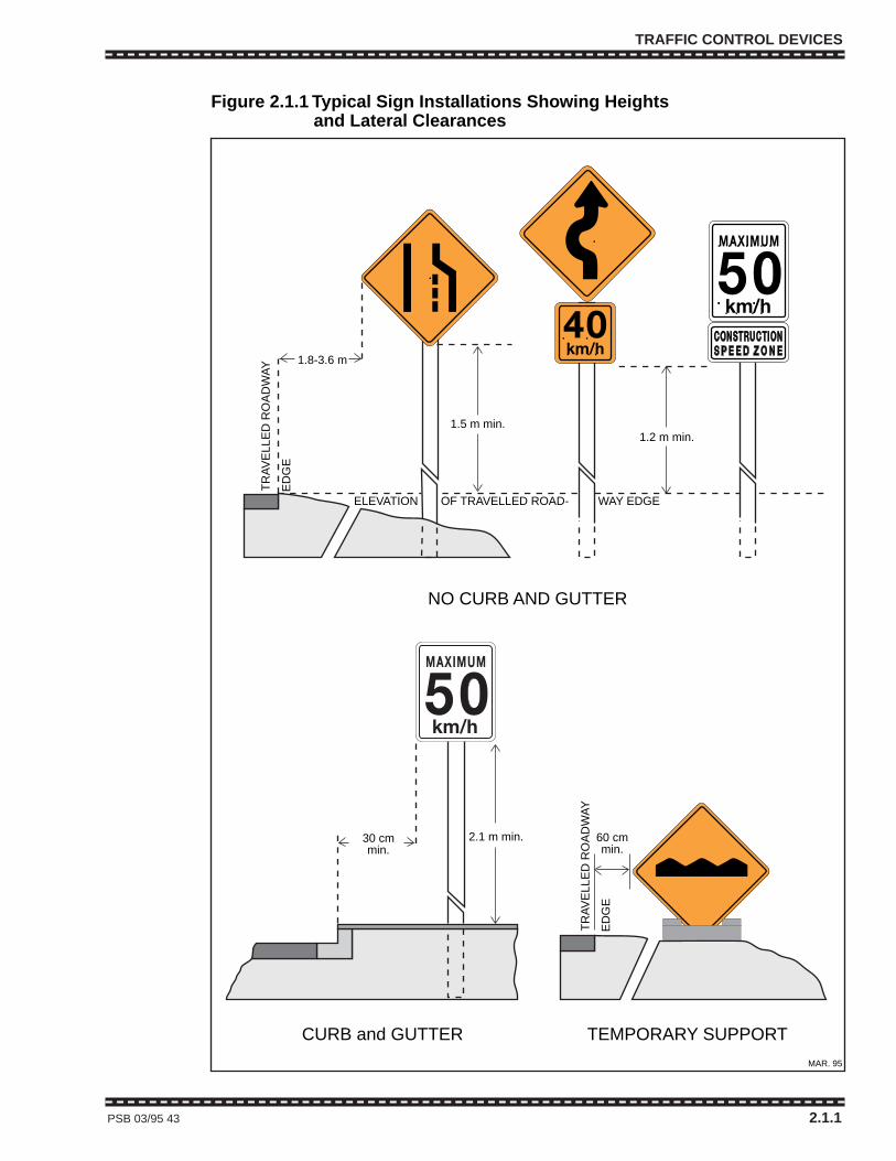
TRAFFIC CONTROL DEVICES
PSB 03/95 43 2.1.1
TR
AV
ELL
ED
RO
AD
WA
Y
ED
GE
1.8-3.6 m
ELEVATION OF TRAVELLED ROAD- WAY EDGE
30 cm min.
60 cmmin.
1.5 m min.1.2 m min.
NO CURB AND GUTTER
CURB and GUTTER TEMPORARY SUPPORT
TR
AV
ELL
ED
RO
AD
WA
Y
ED
GE
2.1 m min.
Figure 2.1.1 Typical Sign Installations Showing HeightsFigure 2.1.1 and Lateral Clearances
MAR. 95
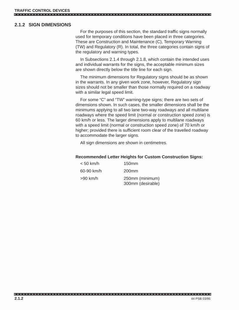
TRAFFIC CONTROL DEVICES
2.1.2 SIGN DIMENSIONSFor the purposes of this section, the standard traffic signs normally
used for temporary conditions have been placed in three categories.These are Construction and Maintenance (C), Temporary Warning(TW) and Regulatory (R). In total, the three categories contain signs ofthe regulatory and warning types.
In Subsections 2.1.4 through 2.1.8, which contain the intended usesand individual warrants for the signs, the acceptable minimum sizesare shown directly below the title line for each sign.
The minimum dimensions for Regulatory signs should be as shownin the warrants. In any given work zone, however, Regulatory signsizes should not be smaller than those normally required on a roadwaywith a similar legal speed limit.
For some “C” and “TW” warning-type signs; there are two sets ofdimensions shown. In such cases, the smaller dimensions shall be theminimums applying to all two lane two-way roadways and all multilaneroadways where the speed limit (normal or construction speed zone) is60 km/h or less. The larger dimensions apply to multilane roadwayswith a speed limit (normal or construction speed zone) of 70 km/h orhigher; provided there is sufficient room clear of the travelled roadwayto accommodate the larger signs.
All sign dimensions are shown in centimetres.
Recommended Letter Heights for Custom Construction Signs:
< 50 km/h 150mm
60-90 km/h 200mm
>90 km/h 250mm (minimum)300mm (desirable)
2.1.2 44 PSB 03/95
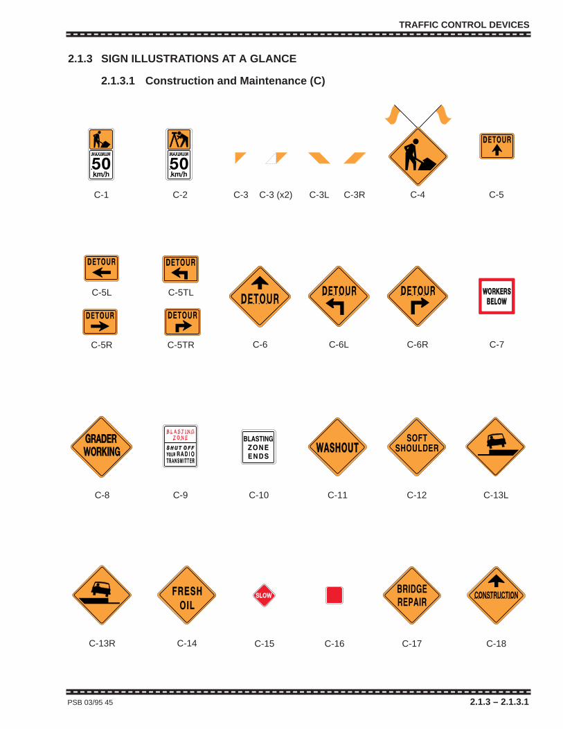
TRAFFIC CONTROL DEVICES
PSB 03/95 45 2.1.3 – 2.1.3.1
2.1.3 SIGN ILLUSTRATIONS AT A GLANCE
2.1.3.1 Construction and Maintenance (C)
C-1 C-2 C-3 C-3 (x2) C-3L C-3R C-4 C-5
C-5R C-5TR
C-5L C-5TL
C-6 C-6L C-6R C-7
C-8 C-9 C-10 C-11 C-12 C-13L
C-13R C-14 C-15 C-16 C-17 C-18
TRAFFIC CONTROL DEVICES
PSB 03/95 45 2.1.3 – 2.1.3.1
2.1.3 SIGN ILLUSTRATIONS AT A GLANCE
2.1.3.1 Construction and Maintenance (C)
C-1 C-2 C-3 C-3 (x2) C-3L C-3R C-4 C-5
C-5R C-5TR
C-5L C-5TL
C-6 C-6L C-6R C-7
C-8 C-9 C-10 C-11 C-12 C-13L
C-13R C-14 C-15 C-16 C-17 C-18
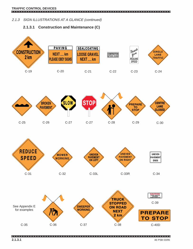
TRAFFIC CONTROL DEVICES
2.1.3 SIGN ILLUSTRATIONS AT A GLANCE (continued)
2.1.3.1 Construction and Maintenance (C)
2.1.3.1 46 PSB 03/95
C-26 C-27 C-27 C-28 C-29 C-30
C-31 C-32 C-33L C-33R C-34
C-20 C-21 C-22 C-23 C-24
C-25
C-19
C-35 C-36 C-37 C-38 C-40D
C-39See Appendix E
for examples
TRAFFIC CONTROL DEVICES
2.1.3 SIGN ILLUSTRATIONS AT A GLANCE (continued)
2.1.3.1 Construction and Maintenance (C)
2.1.3.1 46 PSB 03/95
C-26 C-27 C-27 C-28 C-29 C-30
C-31 C-32 C-33L C-33R C-34
C-20 C-21 C-22 C-23 C-24
C-25
C-19
C-35 C-36 C-37 C-38 C-40D
C-39See Appendix E
for examples

TRAFFIC CONTROL DEVICES
2.1.3 SIGN ILLUSTRATIONS AT A GLANCE (continued)
2.1.3.1 Construction and Maintenance (C)
PSB 03/95 47 2.1.3.1
PAINTSPRAY TRUCK
AHEAD
C-43
C-42S(Back of some
C-42Rs)
C-44 C-45 C-45S
C-41 C-41S
MEANS
WET PAINTNEXT
C-46 C-47
C-48 C-49 C-52RC-52L
C-53 C-54 C-56 C-57
ACCIDENTSCENE
C-58C-55
C-42R
C-42L
C-50 C-51
See Appendix E for examples

TRAFFIC CONTROL DEVICES
2.1.3 SIGN ILLUSTRATIONS AT A GLANCE (continued)
2.1.3.2 Temporary Warning Signs (TW)
2.1.3.2 48 PSB 03/95
TW-11 TW-12 TW-14 TW-15 TW-16 TW-20
TW-22 TW-24 TW-26 TW-27
TW-54L
TW-36L TW-36R
TW-37L TW-37R TW-38 TW-41 TW-49 TW-51
TW-51T TW-54 TW-54R TW-55W TW-55Y
TRAFFIC CONTROL DEVICES
2.1.3 SIGN ILLUSTRATIONS AT A GLANCE (continued)
2.1.3.2 Temporary Warning Signs (TW)
2.1.3.2 48 PSB 03/95
TW-11 TW-12 TW-14 TW-15 TW-16 TW-20
TW-22 TW-24 TW-26 TW-27
TW-54L
TW-36L TW-36R
TW-37L TW-37R TW-38 TW-41 TW-49 TW-51
TW-51T TW-54 TW-54R TW-55W TW-55Y
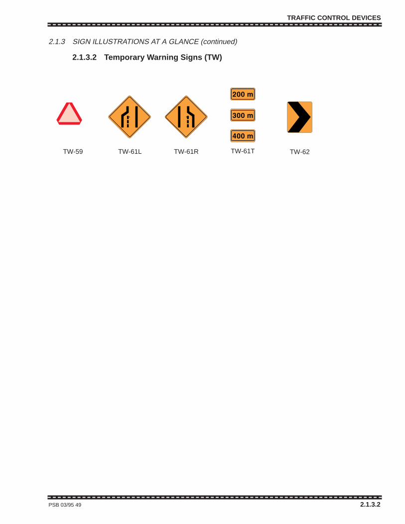
TRAFFIC CONTROL DEVICES
2.1.3 SIGN ILLUSTRATIONS AT A GLANCE (continued)
2.1.3.2 Temporary Warning Signs (TW)
PSB 03/95 49 2.1.3.2
TW-59 TW-61L TW-61R TW-61T TW-62
TRAFFIC CONTROL DEVICES
2.1.3 SIGN ILLUSTRATIONS AT A GLANCE (continued)
2.1.3.2 Temporary Warning Signs (TW)
PSB 03/95 49 2.1.3.2
TW-59 TW-61L TW-61R TW-61T TW-62

TRAFFIC CONTROL DEVICES
2.1.3 SIGN ILLUSTRATIONS AT A GLANCE (continued)
2.1.3.3 Regulatory Signs (R)
2.1.3.3 50 PSB 03/95
R-1 R-1T R-2 R-3 R-4 R-10
R-12
R-12T R-15L R-15R R-18 R-20
R-33L R-33RR-22 R-23 R-35L R-35R
R-125R-56
R-14R
TRAFFIC CONTROL DEVICES
2.1.3 SIGN ILLUSTRATIONS AT A GLANCE (continued)
2.1.3.3 Regulatory Signs (R)
2.1.3.3 50 PSB 03/95
R-1 R-1T R-2 R-3 R-4 R-10
R-12
R-12T R-15L R-15R R-18 R-20
R-33L R-33RR-22 R-23 R-35L R-35R
R-125R-56
R-14R
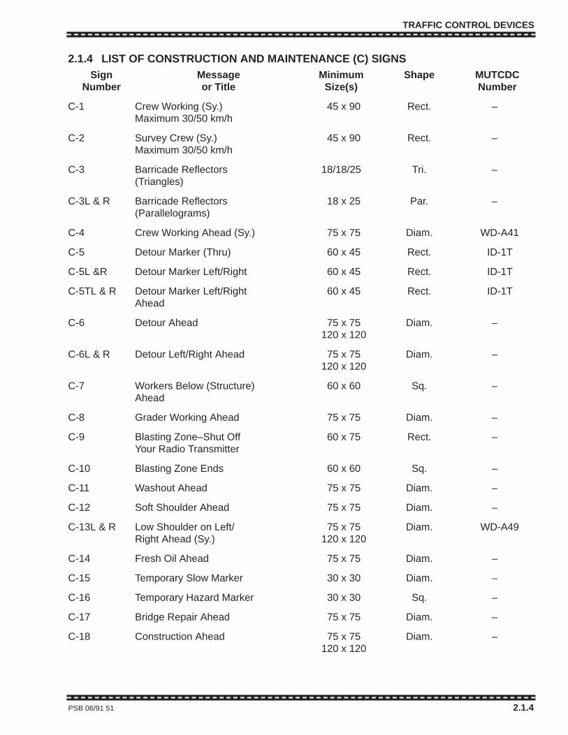
TRAFFIC CONTROL DEVICES
2.1.4 LIST OF CONSTRUCTION AND MAINTENANCE (C) SIGNSSign Message Minimum Shape MUTCDC
Number or Title Size(s) Number
C-1 Crew Working (Sy.) 45 x 90 Rect. –Maximum 30/50 km/h
C-2 Survey Crew (Sy.) 45 x 90 Rect. –Maximum 30/50 km/h
C-3 Barricade Reflectors 18/18/25 Tri. –(Triangles)
C-3L & R Barricade Reflectors 18 x 25 Par. –(Parallelograms)
C-4 Crew Working Ahead (Sy.) 75 x 75 Diam. WD-A41
C-5 Detour Marker (Thru) 60 x 45 Rect. ID-1T
C-5L &R Detour Marker Left/Right 60 x 45 Rect. ID-1T
C-5TL & R Detour Marker Left/Right 60 x 45 Rect. ID-1TAhead
C-6 Detour Ahead 75 x 75 Diam. –120 x 120
C-6L & R Detour Left/Right Ahead 75 x 75 Diam. –120 x 120
C-7 Workers Below (Structure) 60 x 60 Sq. –Ahead
C-8 Grader Working Ahead 75 x 75 Diam. –
C-9 Blasting Zone–Shut Off 60 x 75 Rect. –Your Radio Transmitter
C-10 Blasting Zone Ends 60 x 60 Sq. –
C-11 Washout Ahead 75 x 75 Diam. –
C-12 Soft Shoulder Ahead 75 x 75 Diam. –
C-13L & R Low Shoulder on Left/ 75 x 75 Diam. WD-A49 Right Ahead (Sy.) 120 x 120
C-14 Fresh Oil Ahead 75 x 75 Diam. –
C-15 Temporary Slow Marker 30 x 30 Diam. –
C-16 Temporary Hazard Marker 30 x 30 Sq. –
C-17 Bridge Repair Ahead 75 x 75 Diam. –
C-18 Construction Ahead 75 x 75 Diam. –120 x 120
PSB 06/91 51 2.1.4
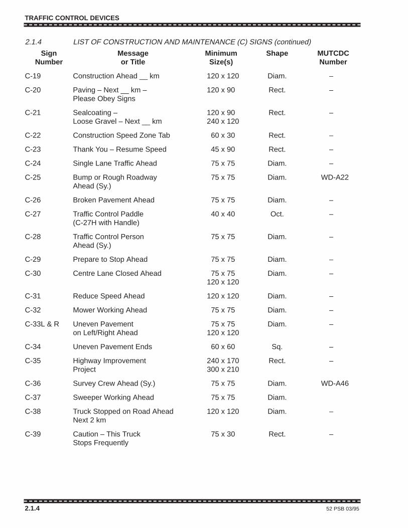
TRAFFIC CONTROL DEVICES
2.1.4 LIST OF CONSTRUCTION AND MAINTENANCE (C) SIGNS (continued)
Sign Message Minimum Shape MUTCDCNumber or Title Size(s) Number
C-19 Construction Ahead __ km 120 x 120 Diam. –
C-20 Paving – Next __ km – 120 x 90 Rect. –Please Obey Signs
C-21 Sealcoating – 120 x 90 Rect. –Loose Gravel – Next __ km 240 x 120
C-22 Construction Speed Zone Tab 60 x 30 Rect. –
C-23 Thank You – Resume Speed 45 x 90 Rect. –
C-24 Single Lane Traffic Ahead 75 x 75 Diam. –
C-25 Bump or Rough Roadway 75 x 75 Diam. WD-A22Ahead (Sy.)
C-26 Broken Pavement Ahead 75 x 75 Diam. –
C-27 Traffic Control Paddle 40 x 40 Oct. –(C-27H with Handle)
C-28 Traffic Control Person 75 x 75 Diam. –Ahead (Sy.)
C-29 Prepare to Stop Ahead 75 x 75 Diam. –
C-30 Centre Lane Closed Ahead 75 x 75 Diam. –120 x 120
C-31 Reduce Speed Ahead 120 x 120 Diam. –
C-32 Mower Working Ahead 75 x 75 Diam. –
C-33L & R Uneven Pavement 75 x 75 Diam. –on Left/Right Ahead 120 x 120
C-34 Uneven Pavement Ends 60 x 60 Sq. –
C-35 Highway Improvement 240 x 170 Rect. –Project 300 x 210
C-36 Survey Crew Ahead (Sy.) 75 x 75 Diam. WD-A46
C-37 Sweeper Working Ahead 75 x 75 Diam.
C-38 Truck Stopped on Road Ahead 120 x 120 Diam. –Next 2 km
C-39 Caution – This Truck 75 x 30 Rect. –Stops Frequently
2.1.4 52 PSB 03/95
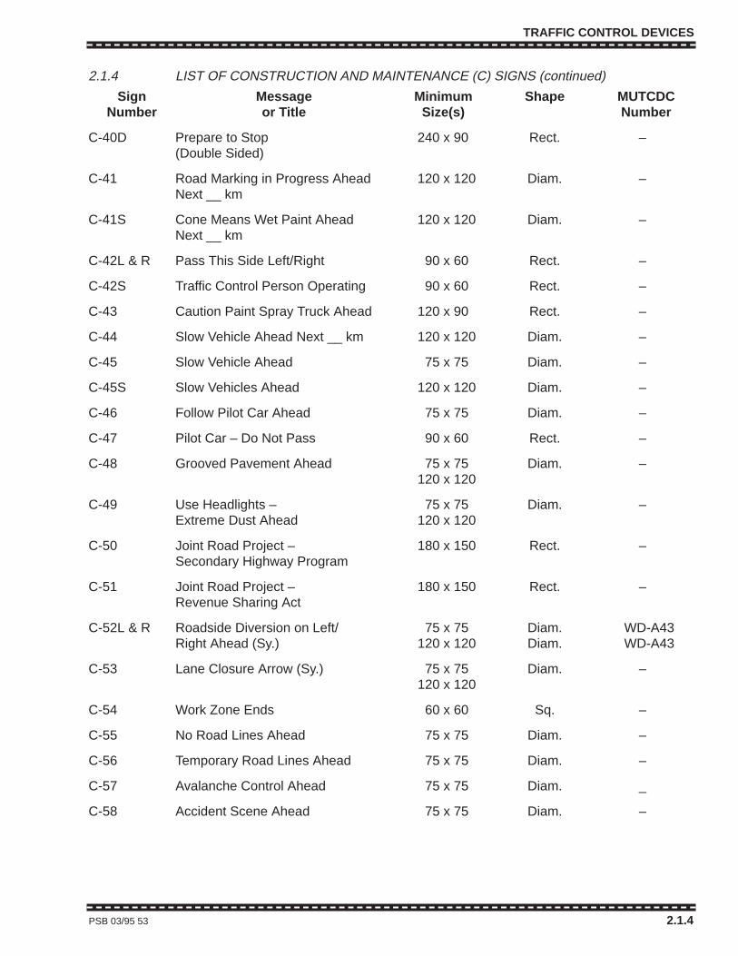
TRAFFIC CONTROL DEVICES
2.1.4 LIST OF CONSTRUCTION AND MAINTENANCE (C) SIGNS (continued)
Sign Message Minimum Shape MUTCDCNumber or Title Size(s) Number
C-40D Prepare to Stop 240 x 90 Rect. –(Double Sided)
C-41 Road Marking in Progress Ahead 120 x 120 Diam. –Next __ km
C-41S Cone Means Wet Paint Ahead 120 x 120 Diam. –Next __ km
C-42L & R Pass This Side Left/Right 90 x 60 Rect. –
C-42S Traffic Control Person Operating 90 x 60 Rect. –
C-43 Caution Paint Spray Truck Ahead 120 x 90 Rect. –
C-44 Slow Vehicle Ahead Next __ km 120 x 120 Diam. –
C-45 Slow Vehicle Ahead 75 x 75 Diam. –
C-45S Slow Vehicles Ahead 120 x 120 Diam. –
C-46 Follow Pilot Car Ahead 75 x 75 Diam. –
C-47 Pilot Car – Do Not Pass 90 x 60 Rect. –
C-48 Grooved Pavement Ahead 75 x 75 Diam. –120 x 120
C-49 Use Headlights – 75 x 75 Diam. –Extreme Dust Ahead 120 x 120
C-50 Joint Road Project – 180 x 150 Rect. –Secondary Highway Program
C-51 Joint Road Project – 180 x 150 Rect. –Revenue Sharing Act
C-52L & R Roadside Diversion on Left/ 75 x 75 Diam. WD-A43 Right Ahead (Sy.) 120 x 120 Diam. WD-A43
C-53 Lane Closure Arrow (Sy.) 75 x 75 Diam. –120 x 120
C-54 Work Zone Ends 60 x 60 Sq. –
C-55 No Road Lines Ahead 75 x 75 Diam. –
C-56 Temporary Road Lines Ahead 75 x 75 Diam. –
C-57 Avalanche Control Ahead 75 x 75 Diam. _
C-58 Accident Scene Ahead 75 x 75 Diam. –
PSB 03/95 53 2.1.4

TRAFFIC CONTROL DEVICES
2.1.4 54 PSB 03/95
TRAFFIC CONTROL DEVICES
2.1.4 54 PSB 03/95
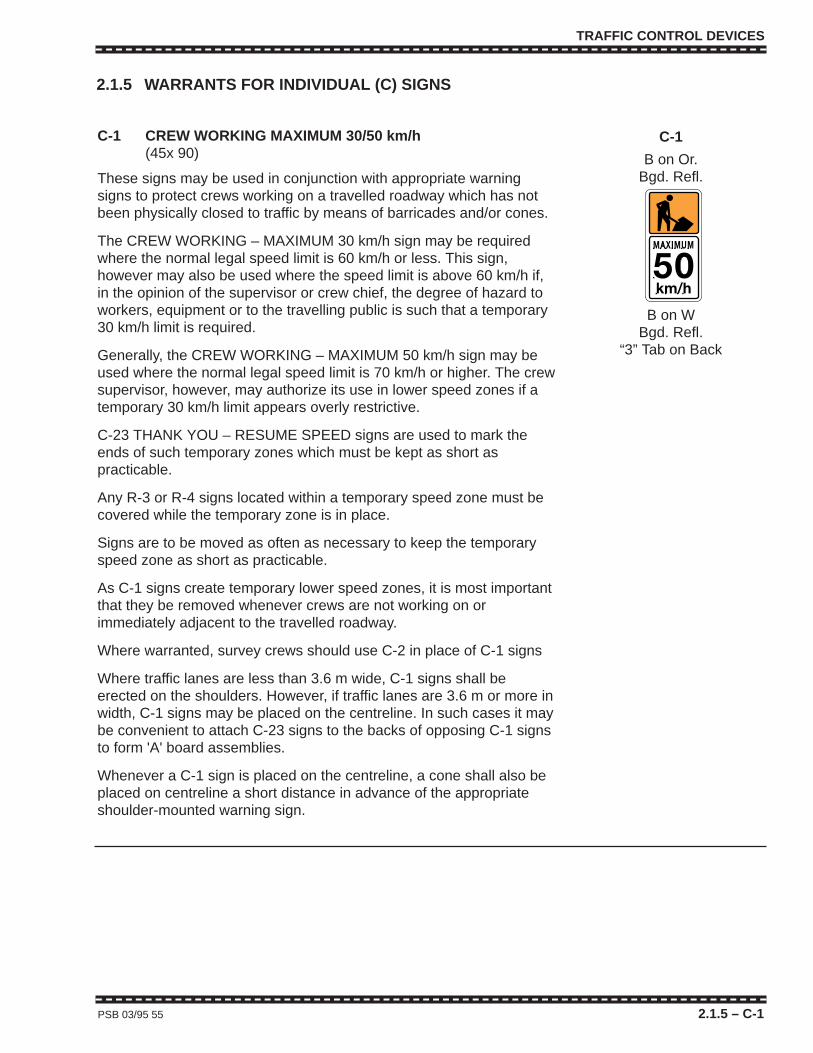
C-1
B on Or.Bgd. Refl.
B on WBgd. Refl.
“3” Tab on Back
TRAFFIC CONTROL DEVICES
C-1 CREW WORKING MAXIMUM 30/50 km/h(45x 90)
These signs may be used in conjunction with appropriate warningsigns to protect crews working on a travelled roadway which has notbeen physically closed to traffic by means of barricades and/or cones.
The CREW WORKING – MAXIMUM 30 km/h sign may be requiredwhere the normal legal speed limit is 60 km/h or less. This sign,however may also be used where the speed limit is above 60 km/h if,in the opinion of the supervisor or crew chief, the degree of hazard toworkers, equipment or to the travelling public is such that a temporary30 km/h limit is required.
Generally, the CREW WORKING – MAXIMUM 50 km/h sign may beused where the normal legal speed limit is 70 km/h or higher. The crewsupervisor, however, may authorize its use in lower speed zones if atemporary 30 km/h limit appears overly restrictive.
C-23 THANK YOU – RESUME SPEED signs are used to mark theends of such temporary zones which must be kept as short aspracticable.
Any R-3 or R-4 signs located within a temporary speed zone must becovered while the temporary zone is in place.
Signs are to be moved as often as necessary to keep the temporaryspeed zone as short as practicable.
As C-1 signs create temporary lower speed zones, it is most importantthat they be removed whenever crews are not working on orimmediately adjacent to the travelled roadway.
Where warranted, survey crews should use C-2 in place of C-1 signs
Where traffic lanes are less than 3.6 m wide, C-1 signs shall beerected on the shoulders. However, if traffic lanes are 3.6 m or more inwidth, C-1 signs may be placed on the centreline. In such cases it maybe convenient to attach C-23 signs to the backs of opposing C-1 signsto form 'A' board assemblies.
Whenever a C-1 sign is placed on the centreline, a cone shall also beplaced on centreline a short distance in advance of the appropriateshoulder-mounted warning sign.
PSB 03/95 55 2.1.5 – C-1
2.1.5 WARRANTS FOR INDIVIDUAL (C) SIGNS
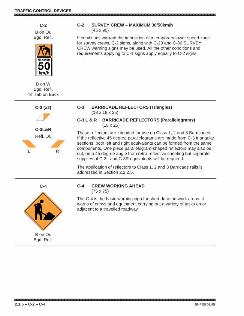
TRAFFIC CONTROL DEVICES
C-2 SURVEY CREW – MAXIMUM 30/50km/h(45 x 90)
If conditions warrant the imposition of a temporary lower speed zonefor survey crews, C-2 signs, along with C-23 and C-36 SURVEYCREW warning signs may be used. All the other conditions andrequirements applying to C-1 signs apply equally to C-2 signs.
2.1.5 – C-2 – C-4 56 PSB 03/95
C-2
B on Or.Bgd. Refl.
B on WBgd. Refl.
“3” Tab on Back
C-4 CREW WORKING AHEAD(75 x 75)
The C-4 is the basic warning sign for short duration work areas. Itwarns of crews and equipment carrying out a variety of tasks on oradjacent to a travelled roadway.
C-4
B on Or.Bgd. Refl.
C-3 BARRICADE REFLECTORS (Triangles)(18 x 18 x 25)
C-3 L & R BARRICADE REFLECTORS (Parallelograms)(18 x 25)
These reflectors are intended for use on Class 1, 2 and 3 Barricades.If the reflective 45 degree parallelograms are made from C-3 triangularsections, both left and right equivalents can be formed from the samecomponents. One piece parallelogram-shaped reflectors may also becut, on a 45 degree angle from retro-reflective sheeting but separatesupplies of C-3L and C-3R equivalents will be required.
The application of reflectors to Class 1, 2 and 3 Barricade rails isaddressed in Section 2.2.2.5.
C-3 (x2)
C-3L&R
Refl. Or.
L R
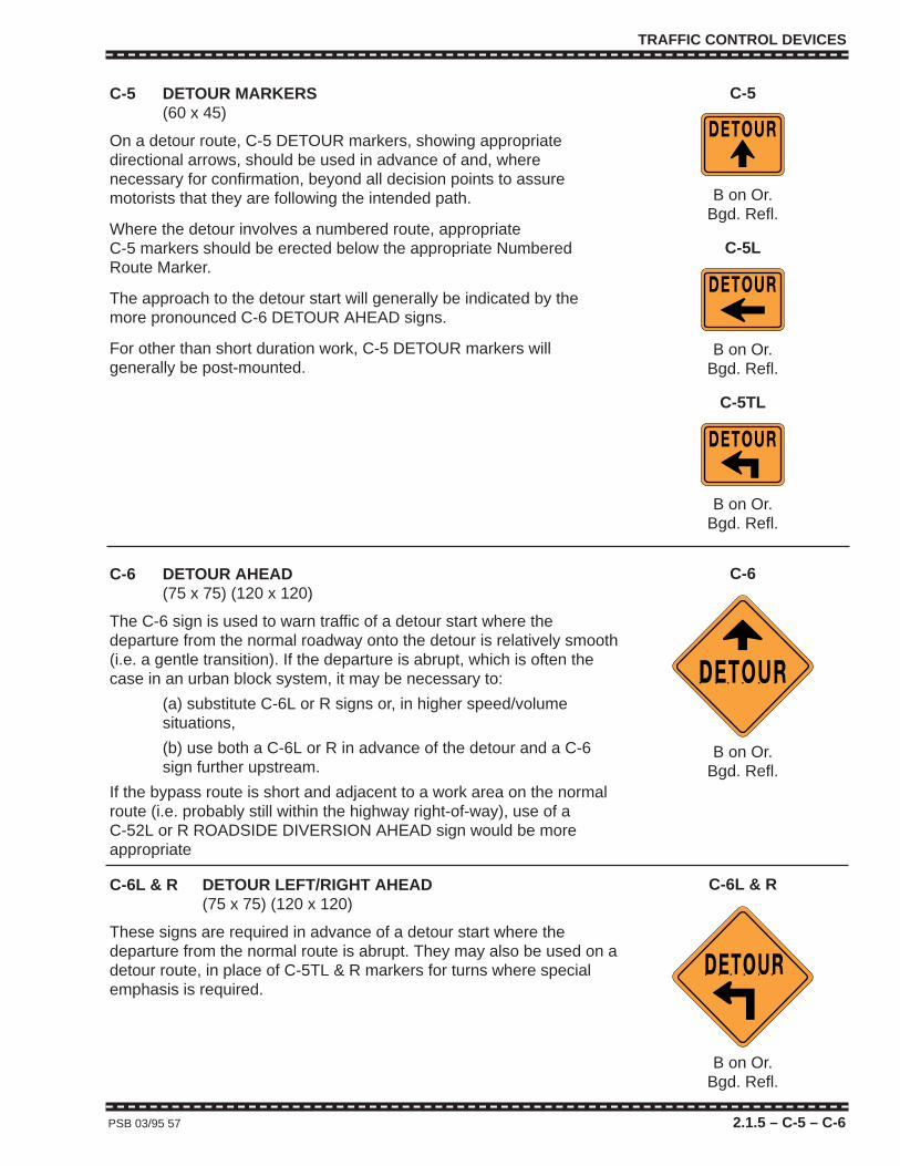
TRAFFIC CONTROL DEVICES
PSB 03/95 57 2.1.5 – C-5 – C-6
C-5 DETOUR MARKERS(60 x 45)
On a detour route, C-5 DETOUR markers, showing appropriatedirectional arrows, should be used in advance of and, wherenecessary for confirmation, beyond all decision points to assuremotorists that they are following the intended path.
Where the detour involves a numbered route, appropriate C-5 markers should be erected below the appropriate NumberedRoute Marker.
The approach to the detour start will generally be indicated by themore pronounced C-6 DETOUR AHEAD signs.
For other than short duration work, C-5 DETOUR markers willgenerally be post-mounted.
C-5
B on Or.Bgd. Refl.
C-6 DETOUR AHEAD(75 x 75) (120 x 120)
The C-6 sign is used to warn traffic of a detour start where thedeparture from the normal roadway onto the detour is relatively smooth(i.e. a gentle transition). If the departure is abrupt, which is often thecase in an urban block system, it may be necessary to:
(a) substitute C-6L or R signs or, in higher speed/volumesituations,
(b) use both a C-6L or R in advance of the detour and a C-6sign further upstream.
If the bypass route is short and adjacent to a work area on the normalroute (i.e. probably still within the highway right-of-way), use of a C-52L or R ROADSIDE DIVERSION AHEAD sign would be moreappropriate
C-6
B on Or.Bgd. Refl.
C-6L & R DETOUR LEFT/RIGHT AHEAD(75 x 75) (120 x 120)
These signs are required in advance of a detour start where thedeparture from the normal route is abrupt. They may also be used on adetour route, in place of C-5TL & R markers for turns where specialemphasis is required.
C-6L & R
B on Or.Bgd. Refl.
C-5L
B on Or.Bgd. Refl.
C-5TL
B on Or.Bgd. Refl.

TRAFFIC CONTROL DEVICES
2.1.5 – C-7 – C-10 58 PSB 03/95
C-7 WORKERS BELOW (Structure) AHEAD(60 x 60)
The C-7 sign may be required to warn the operators of such vehiclesas flusher trucks, snowplows and snow blowers that a crew is workingbelow a structure ahead. Need for the sign shall be determined by thesupervisor of the crew working below after considering such factors asvisibility and exposure of the crew, approach sight distance, approachspeed and prevailing road/ weather conditions.
C-7
B & R on WR & W Refl.
C-8 GRADER WORKING AHEAD(75 x 75)
The C-8 sign shall be used to inform drivers that a grader is workingeither on the shoulder or the travelled roadway ahead. This is one ofthe Continuously Slow Moving Work detailed in Figure 3.2.2.
Where speeds and/or traffic volumes are relatively high and a higherdegree of potential hazard is foreseeable, C-4 CREW WORKINGAHEAD signs should be placed upstream of C-8 signs on bothapproaches to the work area.
If the grading operation warrants the use of a shadow vehicle on theshoulder behind the sweeper, then the C-8 sign for traffic travelling inthe direction of the operation may be displayed conspicuously on therear of the shadow vehicle.
C-8
B on Or.Bgd. Refl.
C-9 BLASTING ZONE – SHUT OFF YOURRADIO TRANSMITTER(60 x 75)
C-10 BLASTING ZONE ENDS(60 x 60)
C-9 BLASTING ZONE – SHUT OFF YOUR RADIO TRANSMITTER,and C-10 BLASTING ZONE ENDS signs shall be used on alloccasions where blasting is carried out in the vicinity of a publicroadway. The C-9 sign shall be placed at least 500 m in advance ofthe blasting zone, and the C-10, 300 m beyond the blasting area.
C-9 and C-10 signs must be removed or covered immediately after aset of charges has been exploded and should not be replaced untilprior to the commencement of loading further drill-holes.
C-9
R on W
B on WR & W Refl.
C-10
B on WBgd. Refl.

TRAFFIC CONTROL DEVICES
PSB 03/95 59 2.1.5 – C-11 – C-13
C-11 WASHOUT AHEAD(75 x 75)
This sign shall be used where a shoulder or part of one travelled lanehas washed out but where there is still sufficient width for two vehiclesto pass safely at reduced speed.
If the washout has encroached far enough to require the closure of alane, traffic control as shown in Figure 3.4.1 or 4.3.1 shall be installed.
Class 1 or 1A Barricades, C-16 TEMPORARY HAZARD markersor other delineation devices shall be used to mark the extent of thewashout.
C-11
B on Or.Bgd. Refl.
C-12 SOFT SHOULDER AHEAD(75 x 75)
The C-12 sign may be used in advance of a section of shoulder whichis newly laid and uncompacted or so softened by weather or othercondition that it presents a hazard to vehicles pulling off the travelledroadway. If the soft shoulder condition is extensive, confirmatory C-12signs may be required.
C-12
B on Or.Bgd. Refl.
C-13 L&R LOW SHOULDER ON LEFT/RIGHT AHEAD(75 x 75)
The LOW SHOULDER sign shall be used on unfinished pavingprojects where the shoulders have not been brought up to the level ofthe new pavement and the drop off is potentially hazardous.
The C-13R sign is erected on the right-hand side of the roadway inadvance of a low shoulder. Where traffic is required to use the left sideof a roadway with a low shoulder, a C-13L sign is erected on the left-hand shoulder.
C-13R
B on Or.Bgd. Refl.

TRAFFIC CONTROL DEVICES
2.1.5 – C-14 – C-16 60 PSB 03/95
C-14 FRESH OIL AHEAD(75 x 75)
On (re)paving, extensive machine patching and sealcoating projects,the C-14 sign shall be used to warn motorists of freshly sprayed liquidasphalt (prime or tack coat) on the road surface. Until the asphalt hascured, it can be slippery and may also result in the objectionablesplashing of vehicles.
Even after the spray has cured, C-14 signs shall be retained until thesprayed area has been covered with new pavement or a sand/chipsealcoat.
The C-14 sign is placed in advance of the sprayed area and repeatedat intervals throughout long sections.
If a cured sprayed section is to remain exposed when work is not inprogress, C-14 signs shall be augmented with TW-41 SLIPPERYWHEN WET signs to warn of potentially increased slipperiness in theevent of rain.
C-14
B on Or.Bgd. Refl.
C-15 TEMPORARY SLOW MARKER(30 x 30)
C-16 TEMPORARY HAZARD MARKER(30 x 30)
The C-15 TEMPORARY SLOW marker is intended for emergency useonly in conjunction with the C-16 TEMPORARY HAZARD marker. Itmay be erected in advance of temporary hazards such as shoulderwashouts, fallen rock, potholes, frost heaves, etc. If it appears thehazard will not be removed promptly the TEMPORARY SLOW Markershould be replaced by an appropriate temporary warning sign, such asC-25 BUMP or ROUGH ROADWAY, C-26 BROKEN PAVEMENT,C-11 WASHOUT, etc., erected under its particular warrant.
If the severity or length of a hazard is such that either or both TW-22ADVISORY SPEED and TW-24 ADVISORY DISTANCE tabs arerequired, then an appropriate temporary warning sign shall be used inplace of the C-15 marker.
The TEMPORARY SLOW marker should not be confused with theTW-21 SLOW sign.
C-16 TEMPORARY HAZARD markers are used with C-15 markersand other temporary warning signs. They are erected on the shoulderto mark the actual site of a hazardous condition. In the case of awashout or minor rock fall, a number of C-16 markers may be requiredto delineate the hazard.
Individual bumps, potholes or pavement breaks will generally requireonly one C-16 marker for each direction of travel.
C-15 and C-16 markers are generally mounted on stakes driven intothe shoulder so that each marker is approximately one metre abovethe level of the travelled roadway.
C-15
W on RFl. Refl.
C-16
W on RFl. Refl.

TRAFFIC CONTROL DEVICES
PSB 03/95 61 2.1.5 – C-17 – C-19
C-17 BRIDGE REPAIR AHEAD(75 x 75)
The C-17 sign may be used in place of C-4 and C-18 signs in advanceof bridge repair projects when the structure is still open to traffic on arestricted basis.
C-17
B on Or.Bgd. Refl.
C-18 CONSTRUCTION AHEAD(75 x 75) (120 x 120)
This sign shall be erected in the Advance Warning Area as indicated inthe Typical Traffic Control Illustrations for long duration work.
C-18
B on Or.Bgd. Refl.
C-19 CONSTRUCTION AHEAD __ km(120 x 120)
The C-19 sign may be used for long duration work zones on amultilane roadways where the normal speed limit is 70 km/h or higherto extend the Advance Warning Area by 1 km or 2 km.
C-19
B on Or.Bgd. Refl.
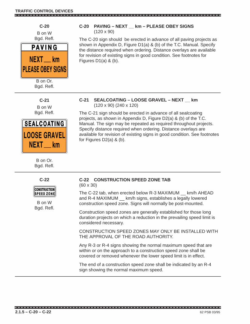
TRAFFIC CONTROL DEVICES
2.1.5 – C-20 – C-22 62 PSB 03/95
C-20 PAVING – NEXT __ km – PLEASE OBEY SIGNS(120 x 90)
The C-20 sign should be erected in advance of all paving projects asshown in Appendix D, Figure D1(a) & (b) of the T.C. Manual. Specifythe distance required when ordering. Distance overlays are availablefor revision of existing signs in good condition. See footnotes forFigures D1(a) & (b).
C-20
B on WBgd. Refl.
B on Or.Bgd. Refl.
C-21
B on WBgd. Refl.
B on Or.Bgd. Refl.
C-21 SEALCOATING – LOOSE GRAVEL – NEXT __ km(120 x 90) (240 x 120)
The C-21 sign should be erected in advance of all sealcoatingprojects, as shown in Appendix D, Figure D2(a) & (b) of the T.C.Manual. The sign may be repeated as required throughout projects.Specify distance required when ordering. Distance overlays areavailable for revision of existing signs in good condition. See footnotesfor Figures D2(a) & (b).
C-22 CONSTRUCTION SPEED ZONE TAB(60 x 30)
The C-22 tab, when erected below R-3 MAXIMUM __ km/h AHEADand R-4 MAXIMUM __ km/h signs, establishes a legally loweredconstruction speed zone. Signs will normally be post-mounted.
Construction speed zones are generally established for those longduration projects on which a reduction in the prevailing speed limit isconsidered necessary.
CONSTRUCTION SPEED ZONES MAY ONLY BE INSTALLED WITHTHE APPROVAL OF THE ROAD AUTHORITY.
Any R-3 or R-4 signs showing the normal maximum speed that arewithin or on the approach to a construction speed zone shall becovered or removed whenever the lower speed limit is in effect.
The end of a construction speed zone shall be indicated by an R-4sign showing the normal maximum speed.
C-22
B on WBgd. Refl.
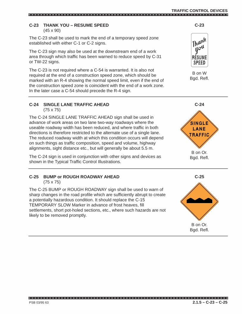
TRAFFIC CONTROL DEVICES
PSB 03/95 63 2.1.5 – C-23 – C-25
C-23 THANK YOU – RESUME SPEED(45 x 90)
The C-23 shall be used to mark the end of a temporary speed zoneestablished with either C-1 or C-2 signs.
The C-23 sign may also be used at the downstream end of a workarea through which traffic has been warned to reduce speed by C-31or TW-22 signs.
The C-23 is not required where a C-54 is warranted. It is also notrequired at the end of a construction speed zone, which should bemarked with an R-4 showing the normal speed limit, even if the end ofthe construction speed zone is coincident with the end of a work zone.In the later case a C-54 should precede the R-4 sign.
C-23
B on WBgd. Refl.
C-24 SINGLE LANE TRAFFIC AHEAD(75 x 75)
The C-24 SINGLE LANE TRAFFIC AHEAD sign shall be used inadvance of work areas on two lane two-way roadways where theuseable roadway width has been reduced, and where traffic in bothdirections is therefore restricted to the alternate use of a single lane.The reduced roadway width at which this condition occurs will dependon such things as traffic composition, speed and volume, highwayalignments, sight distance etc., but will generally be about 5.5 m.
The C-24 sign is used in conjunction with other signs and devices asshown in the Typical Traffic Control Illustrations.
C-24
B on Or.Bgd. Refl.
C-25 BUMP or ROUGH ROADWAY AHEAD(75 x 75)
The C-25 BUMP or ROUGH ROADWAY sign shall be used to warn ofsharp changes in the road profile which are sufficiently abrupt to createa potentially hazardous condition. It should replace the C-15TEMPORARY SLOW Marker in advance of frost heaves, fillsettlements, short pot-holed sections, etc., where such hazards are notlikely to be removed promptly.
C-25
B on Or.Bgd. Refl.
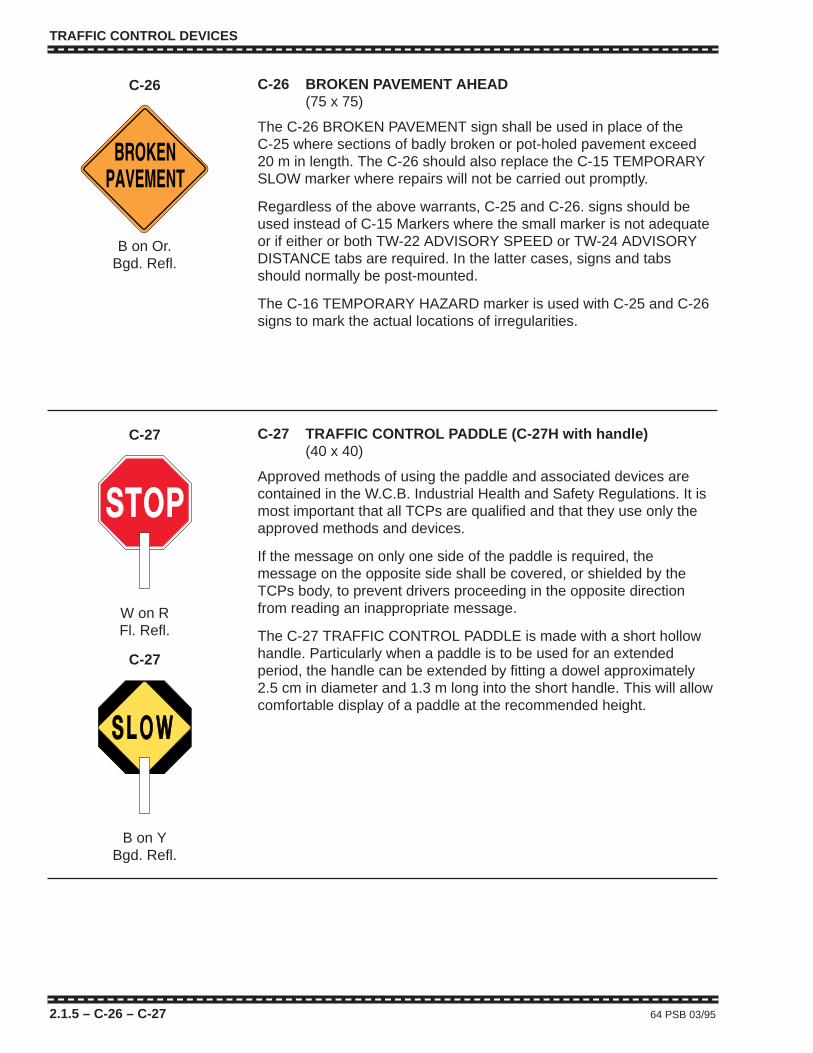
TRAFFIC CONTROL DEVICES
2.1.5 – C-26 – C-27 64 PSB 03/95
C-26 BROKEN PAVEMENT AHEAD(75 x 75)
The C-26 BROKEN PAVEMENT sign shall be used in place of theC-25 where sections of badly broken or pot-holed pavement exceed20 m in length. The C-26 should also replace the C-15 TEMPORARYSLOW marker where repairs will not be carried out promptly.
Regardless of the above warrants, C-25 and C-26. signs should beused instead of C-15 Markers where the small marker is not adequateor if either or both TW-22 ADVISORY SPEED or TW-24 ADVISORYDISTANCE tabs are required. In the latter cases, signs and tabsshould normally be post-mounted.
The C-16 TEMPORARY HAZARD marker is used with C-25 and C-26signs to mark the actual locations of irregularities.
C-26
B on Or.Bgd. Refl.
C-27 TRAFFIC CONTROL PADDLE (C-27H with handle) (40 x 40)
Approved methods of using the paddle and associated devices arecontained in the W.C.B. Industrial Health and Safety Regulations. It ismost important that all TCPs are qualified and that they use only theapproved methods and devices.
If the message on only one side of the paddle is required, themessage on the opposite side shall be covered, or shielded by theTCPs body, to prevent drivers proceeding in the opposite directionfrom reading an inappropriate message.
The C-27 TRAFFIC CONTROL PADDLE is made with a short hollowhandle. Particularly when a paddle is to be used for an extendedperiod, the handle can be extended by fitting a dowel approximately2.5 cm in diameter and 1.3 m long into the short handle. This will allowcomfortable display of a paddle at the recommended height.
C-27
W on RFl. Refl.
C-27
B on YBgd. Refl.
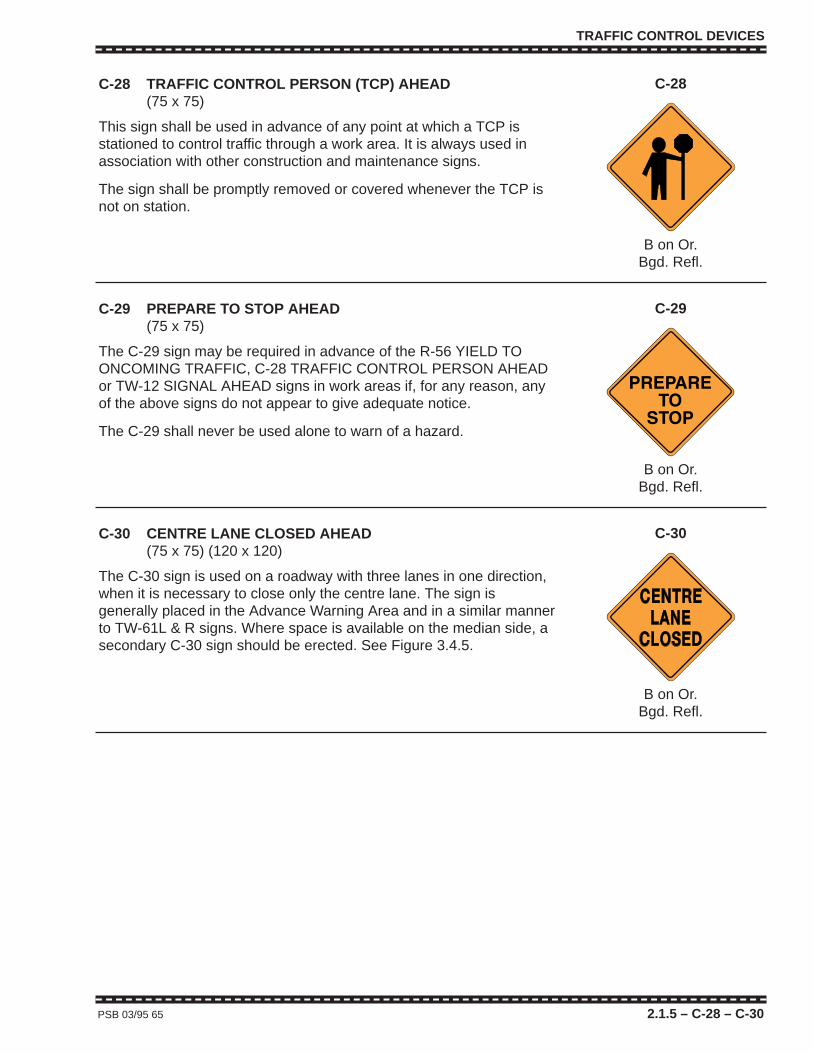
TRAFFIC CONTROL DEVICES
PSB 03/95 65 2.1.5 – C-28 – C-30
C-28 TRAFFIC CONTROL PERSON (TCP) AHEAD (75 x 75)
This sign shall be used in advance of any point at which a TCP isstationed to control traffic through a work area. It is always used inassociation with other construction and maintenance signs.
The sign shall be promptly removed or covered whenever the TCP isnot on station.
C-28
B on Or.Bgd. Refl.
C-29 PREPARE TO STOP AHEAD (75 x 75)
The C-29 sign may be required in advance of the R-56 YIELD TOONCOMING TRAFFIC, C-28 TRAFFIC CONTROL PERSON AHEADor TW-12 SIGNAL AHEAD signs in work areas if, for any reason, anyof the above signs do not appear to give adequate notice.
The C-29 shall never be used alone to warn of a hazard.
C-29
B on Or.Bgd. Refl.
C-30 CENTRE LANE CLOSED AHEAD(75 x 75) (120 x 120)
The C-30 sign is used on a roadway with three lanes in one direction,when it is necessary to close only the centre lane. The sign isgenerally placed in the Advance Warning Area and in a similar mannerto TW-61L & R signs. Where space is available on the median side, asecondary C-30 sign should be erected. See Figure 3.4.5.
C-30
B on Or.Bgd. Refl.

TRAFFIC CONTROL DEVICES
2.1.5 – C-31 – C-32 66 PSB 03/95
C-31 REDUCE SPEED AHEAD(120 x 120)
The C-31 sign may be used in conjunction with the C-30 and TW-61L & R signs, in the Advance Warning Area, on multilanehighways where the speed limit is 70 km/h or higher. It is not requiredwhere a construction speed zone has been established but can beuseful in slowing traffic without the imposition of a lower legal speedrequirement.
C-31
B on Or.Bgd. Refl.
C-32 MOWER WORKING AHEAD(75 x 75)
This sign shall be used to warn motorists that a mower is workingadjacent to the roadway and that the operator, in avoiding suchobstructions as culvert ends, delineators and sign posts, etc., mayencroach onto the shoulder or even into the travelled lane if theshoulder is narrow. If the mower is consistently working well clear ofthe travelled roadway and shoulder, the C-32 sign is not required.
If the mowing operation warrants the use of a shadow vehicle on theshoulder behind the mower, then the C-32 sign for traffic travelling inthe direction of the operation may be displayed conspicuously on therear of the shadow vehicle.
C-32
B on Or.Bgd. Refl.

TRAFFIC CONTROL DEVICES
PSB 03/95 67 2.1.5 – C-33 – C-35
C-33L & R UNEVEN PAVEMENT ON LEFT/RIGHT AHEAD(60 x 60) (120 x 120)
C-34 UNEVEN PAVEMENT ENDS(60 x 60)
The C-33L & R signs warn of a difference in elevation betweenpavement lifts on adjacent travelled lanes. The C-13 LOWSHOULDER ON LEFT/RIGHT signs warn of a difference in elevationbetween the shoulder and the outer edge of a newly paved roadway.
If traffic is not controlled by TCPs and/or a pilot car, C-33 signs shallbe used in a paving work area to warn of uneven pavement lifts at thecentreline or lane lines which are potentially hazardous.
On two lane two-way roads, the uneven hazard (high or low) willgenerally be on centreline and C-33L signs are used, for bothdirections of travel, in advance of and possibly for confirmation throughthe section.
On multilane roadways, the uneven hazard will generally be on thelane line. In such cases, C-33L signs are be placed on the rightshoulder and, where space is available, C-33R signs on the left ormedian shoulder.
The C-34 sign shall be used to mark the end of an uneven section ofpavement.
The locations of C-33 and C-34 signs require frequent adjustment aspaving progresses.
C-33L
B on Or.Bgd. Refl.
C-34
B on WBgd. Refl.
C-35 HIGHWAY IMPROVEMENT PROJECT
There are a number of different C-35 and C-50/C-51 HIGHWAYIMPROVEMENT PROJECT signs used for Provincially and jointlyfunded long duration work zones. These are detailed in Appendix E.

TRAFFIC CONTROL DEVICES
2.1.5 – C-36 – C-38 68 PSB 03/95
C-36 SURVEY CREW AHEAD(75 x 75)
The C-36 sign shall be used where survey work is in progress on orimmediately adjacent to a travelled roadway which has not beenclosed to traffic. It may be used alone or in conjunction with the C-2SURVEY CREW – MAXIMUM (Speed) 30/50 km/h signs, if the crewsupervisor considers that conditions warrant the imposition of atemporary lower speed zone.
C-36
B on Or.Bgd. Refl.
C-37 SWEEPER WORKING AHEAD(75 x 75)
The C-37 sign shall be used in advance of a section where amechanical sweeper is used to clean a paved roadway or shoulder.This is one of the Continuously Slow Moving Work detailed in Figures3.2.2 and 3.2.3.
Where a travelled lane, as opposed to a shoulder, is being swept on atwo lane two-way roadway, a second C-37 sign shall be erected toface opposing traffic beyond the end of the section being cleaned(maximum 8 km) and an R-56 YIELD TO ONCOMING TRAFFIC signshall be displayed on the rear of the sweeper.
If the sweeping operation warrants the use of a shadow vehicle, on theshoulder behind the sweeper, then the C-37 sign for traffic travelling inthe direction of the operation may be displayed conspicuously on therear of the shadow vehicle.
C-37
B on Or.Bgd. Refl.
C-38 TRUCK STOPPED ON ROAD AHEAD NEXT __ km(Maximum 2 km)(120 x 120)
As shown in Figure 3.2.1, the C-38 sign shall be used on two lane two-way roadways in advance of Intermittent Moving Work such asBenkleman beam testing, crack sealing, temporary patching, andreflective road stud installation, etc. Either flags or a Type B portableFlashing Yellow Light, as specified in Section 2.2.4, shall be mounteddirectly above each C-38 sign. The sign may also be supplemented bya HLWD to increase visibility. A C-28 TCP AHEAD sign shall beerected downstream of the C-38 and these pairs of signs may remainstationary as the crew works through a section.
The maximum distance between two opposing C-38 signs should notexceed 2 km except for Falling Weight Deflectometer operations onrural highways where it should not exceed 8 km.
C-38
B on Or.Bgd. Refl.

TRAFFIC CONTROL DEVICES
PSB 03/95 69 2.1.5 – C-39 – C-41
C-39 CAUTION – THIS TRUCK STOPS FREQUENTLY(75 x 30)
This is a special purpose sign which shall be displayed on the rear ofvehicles involved with Intermittent Moving Work on an open travelledlane of a two lane two-way highway. The sign should be removed orcovered when work is not in progress and the vehicle is driven atnormal highway speeds.
C-39
B & R on WR & W Refl.
C-41 ROAD MARKING IN PROGRESS AHEAD NEXT ___ km(Maximum 10 km)(120 x 120)
This sign shall be located in advance of pavement marking operationson two lane two-way rural roads as shown in Appendix B, Figure B.1 ofthe T.C. Manual. The maximum distance shown on the sign is 10 km.However, it may be necessary, when a striper is operating at higherspeed, and there are practical limits on the personnel and vehiclesavailable for signing, to have as many as three sets of these signs inplace at one time over a maximum distance of 30 km.
C-41
B on Or.Bgd. Refl.
C-40D PREPARE TO STOP(240 x 90)
This is a special purpose double-sided sign that shall be mountedprominently atop Benkleman beam testing vehicles and other vehiclesinvolved with Intermittent Moving Work in a travelled lane on a twolane two-way roadway. It should be lowered or removed whenever thevehicle is no longer blocking the travelled lane.
To alleviate mounting difficulties on some types of vehicles, a squarerversion of the C-40D may be considered, provided face area and letterheight are not overly compromised.
C-40D
B on Or.Bgd. Refl.

TRAFFIC CONTROL DEVICES
2.1.5 – C-41 S – C-43 70 PSB 03/95
C-43 CAUTION PAINT SPRAY TRUCK AHEAD(120 x 90)
This sign shall be displayed on the front of a buffer vehicle preceding aworking paint striper. The buffer vehicle with sign, which is straddlingthe line to be painted, forces opposing traffic away from the striper andin so doing, minimizes the possibility of collision and problems withoverspray.
C-43
B & R on WR & W Refl.
PAINTSPRAY TRUCK
AHEAD
C-42 L & R PASS THIS SIDE LEFT/RIGHT(90 x 60)
C-42 S TRAFFIC CONTROL PERSON (TCP) OPERATING(90 x 60) (Back of some C-42Rs)
This sign with the appropriate arrow shall be displayed on the rear of apaint striper and the rear of a buffer truck, or as required on othervehicles in a pavement marking operation where a FAB (arrow mode)is not available or used.
This is a double sided sign with a C-42 L & R rotated 180° on oppositesides. It is also available with a C-42S on the reverse side of a C-42R.
The C-42 S is to be displayed on the rear of the striper when a TCP iscontrolling traffic from the back of a striper.
C-42L
B & R on WR & W Refl.
C-42S
B & Or.Bgd. Refl.
C-41 S (Traffic cone Symbol) MEANS WET PAINT AHEADNEXT ___ km (Maximum 10 km)(120 x 120)
This sign is used to supplement the C-41 sign. It is not for use whereinstallation of plastic marking, road studs or prelining marking is beingcarried out.
This sign is mounted on the back of the same sign blank as a C-41 butrotated 180°.
C-41 S
B and Dayglo Or. on Or.Bgd. Refl.
MEANS
WET PAINTNEXT
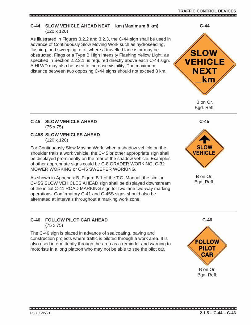
TRAFFIC CONTROL DEVICES
PSB 03/95 71 2.1.5 – C-44 – C-46
C-46 FOLLOW PILOT CAR AHEAD(75 x 75)
The C-46 sign is placed in advance of sealcoating, paving andconstruction projects where traffic is piloted through a work area. It isalso used intermittently through the area as a reminder and warning tomotorists in a long platoon who may not be able to see the pilot car.
C-46
B on Or.Bgd. Refl.
C-44 SLOW VEHICLE AHEAD NEXT _ km (Maximum 8 km)(120 x 120)
As illustrated in Figures 3.2.2 and 3.2.3, the C-44 sign shall be used inadvance of Continuously Slow Moving Work such as hydroseeding,flushing, and sweeping, etc., where a travelled lane is or may beobstructed. Flags or a Type B High Intensity Flashing Yellow Light, asspecified in Section 2.2.3.1, is required directly above each C-44 sign.A HLWD may also be used to increase visibility. The maximumdistance between two opposing C-44 signs should not exceed 8 km.
C-44
B on Or.Bgd. Refl.
C-45 SLOW VEHICLE AHEAD(75 x 75)
C-45S SLOW VEHICLES AHEAD(120 x 120)
For Continuously Slow Moving Work, when a shadow vehicle on theshoulder trails a work vehicle, the C-45 or other appropriate sign shallbe displayed prominently on the rear of the shadow vehicle. Examplesof other appropriate signs could be C-8 GRADER WORKING, C-32MOWER WORKING or C-45 SWEEPER WORKING.
As shown in Appendix B, Figure B.1 of the T.C. Manual, the similarC-45S SLOW VEHICLES AHEAD sign shall be displayed downstreamof the initial C-41 ROAD MARKING sign for two lane two-way markingoperations. Confirmatory C-41 and C-45S signs should also bealternated at intervals throughout a marking work zone.
C-45
B on Or.Bgd. Refl.

TRAFFIC CONTROL DEVICES
2.1.5 – C-47 – C-51 72 PSB 03/95
C-50 JOINT ROAD PROJECT – SECONDARY HIGHWAY PROGRAM
C-51 JOINT ROAD PROJECT – REVENUE SHARING ACT
Details of HIGHWAY IMPROVEMENT PROJECT signs for theserevenue sharing programs are contained in Appendix E.
C-47 PILOT CAR – DO NOT PASS(120 x 90)
The C-47 sign shall be mounted prominently on the top of pilotvehicles with the message shown facing to the rear. Only the words“PILOT CAR”, on the opposite side of the sign, are displayed to thefront. The sign shall be removed or folded down whenever the vehicleis not piloting traffic.
C-47
B on WBgd. Refl.
C-48 GROOVED PAVEMENT AHEAD(75 x 75) (120 x 120)
The C-48 sign shall be used in advance of (and as required forconfirmation throughout) sections of milled pavement wherelongitudinal grooves and ridges can radically effect the handlingcharacteristics of two-wheeled vehicles.
C-48
B on Or.Bgd. Refl.
C-49 USE HEADLIGHTS – EXTREME DUST AHEAD(75 x 75) (120 x120)
The C-49 sign should be used in advance of newly sealcoated or otherdry gravel or dirt road surfaces where blowing dust, raised by wind ormoving vehicles, is thick enough to interfere with visibility. On longersections, the sign may be repeated for confirmation.
C-49
B on Or.Bgd. Refl.

TRAFFIC CONTROL DEVICES
PSB 03/95 73 2.1.5 – C-52 – C-54
C-53
B on Or.Bgd. Refl.
C-52L & R ROADSIDE DIVERSION ON LEFT/RIGHT AHEAD(75 x 75) (120 x 120)
A diversion is a “mini detour”, usually adjacent to the normal route, bywhich traffic is diverted around a short work area. Transition from andback to the normal route should not be abrupt. The C-52L or R sign inadvance indicates the path for drivers to follow.
Diversions can involve both lanes of a two lane two-way roadway orone two lane roadway of a multilane highway. In the latter case, C-52signs should be placed on both sides of the roadway, approaching thediversion, if the highway is divided and space is available for a sign inthe median.
C-52R
B on Or.Bgd. Refl.
C-53 LANE CLOSURE ARROW(75 x 75) (120 x 120)
Where required, for a lane closure on a multilane highway, this sign iserected just inside the closed-off area at the start of the lane closuretaper. It is oriented with the arrow 45 degrees above horizontal andpointing in the transverse shift direction. It should be mounted highenough above the taper devices to be seen clearly by approachingtraffic.
The C-53 sign may be omitted in situations where a FAB, (in arrowmode) is used in the lane closure taper area. But if either a HLWD or a360 degree flashing yellow light and 4-way flashers are allowed inplace of a FAB, the C-53 sign is required. For an inactive long durationwork area, where a FAB in a taper area is replaced, for example, by aseries of Type A flashing yellow lights or Type C steady burn yellowlights, the C-53 sign is required.
For a short duration work area in the centre of a two lane two-wayroadway, where traffic in both directions is required to pass the site onthe right (and FABs are not called for), a C-53 sign may be providedfor either or both directions if the intended paths are not self evident.
C-54 WORK ZONE ENDS(60 x 60)
The C-54 sign should be used to indicate the end of any work areamarked with C-35 HIGHWAY IMPROVEMENT PROJECT signs. Itshould also be used to mark the end of any other lengthy work area ifthat point is not self evident to drivers. Very short work areas willgenerally not require a C-54. A C-54 should be erected at the end ofthe area in which work is in progress rather than the end of the project.It must not be erected within another work area (e.g., an adjacentactive contract). It is not required where a C-23 is warranted.
C-54
B on WBgd. Refl.

TRAFFIC CONTROL DEVICES
2.1.5 – C-55 – C-58 74 PSB 03/95
C-55 NO ROAD LINES AHEAD(75 x 75)
C-56 TEMPORARY ROAD LINES AHEAD(75 x 75)
See Sec. 2.2.1 regarding requirements for installation of temporaryand standard permanent markings.
Where a roadway which would normally have pavement markings hasno permanent pavement markings in place, and is carrying traffic, oneof these two signs should be installed. A C-55 sign is required if thereare no pavement markings in place or a C-56 sign if there aretemporary markings in place. Worksites where this typically occursinvolve paving, sealcoating, milling, centreline crack sealing etc.
If a section of road without permanent pavement markings exceeds2 km in length, a TW-24 ADVISORY DISTANCE tab should bemounted below the C-55 or C-56 sign.
C-55 and C-56 signs may be produced back-to-back provided onemessage is inverted with respect to the other.
C-57 AVALANCHE CONTROL AHEAD(75 x 75)
This sign is required with others in advance of road closures foravalanches and avalanche control works. There should be flags or aType B High Intensity Flashing Yellow Light mounted directly above thesign. For positioning of the sign see Appendix A of the T.C. Manual. Allsigns relating to avalanche closures must be removed or coveredwhen not required.
C-55
B on Or.Bgd. Refl.
C-56
B on Or.Bgd. Refl.
C-57
B on Or.Bgd. Refl.
C-58 ACCIDENT SCENE AHEAD(75 x 75)
C-58 signs may be used in place of C-4 and C-18 signs for operationswhere tow trucks are involved in the recovery of motor vehicles andwhere those operations could effect the normal movements of publictraffic.
C-58
B on Or.Bgd. Refl.
ACCIDENTSCENE

TRAFFIC CONTROL DEVICES
2.1.6 LIST OF TEMPORARY WARNING (TW) SIGNS **Sign Message Minimum Shape MUTCDC
Number or Title Size(s) Number
TW-11 Stop Ahead (Sy.) 75 x 75 Diam. WD-B1
TW-12 Traffic Signal Ahead (Sy.) 75 x 75 Diam. WD-B4
TW-14 Checkerboard (Plain) (Sy.) 75 x 75 Diam. WD-A8
TW-15 Checkerboard (Single Arrow) (Sy.) 75 x 75 Diam. WD-A84R120 x 120 WD-A84R
TW-16 Checkerboard (Double Arrow) (Sy.) 75 x 75 Diam. WD-A8D120 x 120 WD-A8D
TW-20 Two-way Traffic Ahead (Sy.) 75 x 75 Diam. WD-B3120 x 120 WD-B3
TW-22 Advisory Speed Tab 45 x 45 Sq. WD-A7
TW-24 Advisory Distance Tab 45 x 45 Sq. –
TW-26 Road Narrows Ahead (Sy.) 75 x 75 Diam. WD-A23
TW-27 Loose Gravel Ahead 75 x 75 Diam. –
TW-36L & R Truck Crossing/Entrance 75 x 75 Diam. –Left/Right Ahead (Sy.)
TW-37L & R Merging Traffic Left/ 75 x 75 Diam. –Right Ahead (Sy.)
TW-38 Merge Ahead 75 x 75 Diam. –
TW-41 Slippery Ahead When Wet (Sy.) 75 x 75 Diam WD-C5
TW-49 Pavement Ends Ahead (Sy.) 75 x 75 Diam. WD-A25
TW-51 Narrow Structure Ahead (Sy.) 75 x 75 Diam. WD-A24
TW-51T One Lane Tab 60 x 30 Rect. WD-A24T
TW-54 Double Hazard Marker 30 x 90 Rect. –
TW-54L & R Left/Right Hazard Marker 30 x 90 Rect. –
TW-55W & Y Delineator Reflectors 7.6 x 20 Rect. –
TW-59 Slow Moving Vehicle Marker 35/35/35 Tri. –
TW-61L & R Left/Right Lane Closed Ahead (Sy.) 75 x 75 Diam. WD-A33120 x 120 WD-A33
TW-61T 200 m, 300 m, 400 m Tab 60 x 30 Rect. –
TW-62 Chevron Alignment Marker (Sy.) 60 x 75 Rect. WD-A9
Continued on next page…
PSB 03/95 75 2.1.6
TRAFFIC CONTROL DEVICES
2.1.6 76 PSB 03/95
Continued from previous page…
** The prefix letters “TW” identify temporary warning signs.
“TW” signs are almost identical to “W” (permanent) warning signs withthe same numbers except that the former have orange backgrounds andthe latter yellow. The exceptions are the TW-55W & Y DELINEATORREFLECTORS which are the same colours as for permanent conditions.
The “TW” signs listed above (and more fully described in the followingpages) are some of the most commonly used. For different temporarywarning situations, other black and yellow “W” (permanent) warningsigns, contained in “The British Columbia Manual of Standard TrafficSigns” or the “Manual of Uniform Traffic Control Devices for Canada” canbe converted to their “TW” equivalents by using orange backgrounds.
Black and orange warning-type signs in the “C” series are always used intemporary situations. They differ from “TW” signs only in that they do nothave black and yellow “W” equivalents.
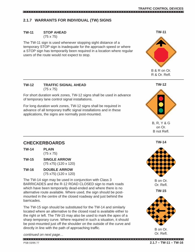
TRAFFIC CONTROL DEVICES
PSB 03/95 77 2.1.7 – TW-11 – TW-16
TW-11 STOP AHEAD(75 x 75)
The TW-11 sign is used whenever stopping sight distance of atemporary STOP sign is inadequate for the approach speed or wherea STOP sign has temporarily been required in a location where regularusers of the route would not expect to stop.
TW-11
B & R on Or.R & Or. Refl.
TW-12 TRAFFIC SIGNAL AHEAD(75 x 75)
For short duration work zones, TW-12 signs shall be used in advanceof temporary lane control signal installations.
For long duration work zones, TW-12 signs shall be required inadvance of all temporary traffic signal installations and in theseapplications, the signs are normally post-mounted.
TW-12
B, R, Y & Gon Or.
B not Refl.
CHECKERBOARDSTW-14 PLAIN
(75 x 75)
TW-15 SINGLE ARROW(75 x75) (120 x 120)
TW-16 DOUBLE ARROW(75 x75) (120 x 120)
The TW-14 sign may be used in conjunction with Class 3BARRICADES and the R-12 ROAD CLOSED sign to mark roadswhich have been temporarily dead-ended and where there is noalternative route available. Where used, the sign should be post-mounted in the centre of the closed roadway and just behind thebarricades.
The TW-15 sign should be substituted for the TW-14 and similarlylocated where an alternative to the closed road is available either tothe right or left. The TW-15 may also be used to mark the apex of asharp temporary curve. Where required in such a situation, it shouldbe post-mounted just off the shoulder on the outside of the curve anddirectly in line with the path of approaching traffic.
continued on next page…
TW-14
B on Or.Or. Refl.
TW-15
B on Or.Or. Refl.
2.1.7 WARRANTS FOR INDIVIDUAL (TW) SIGNS
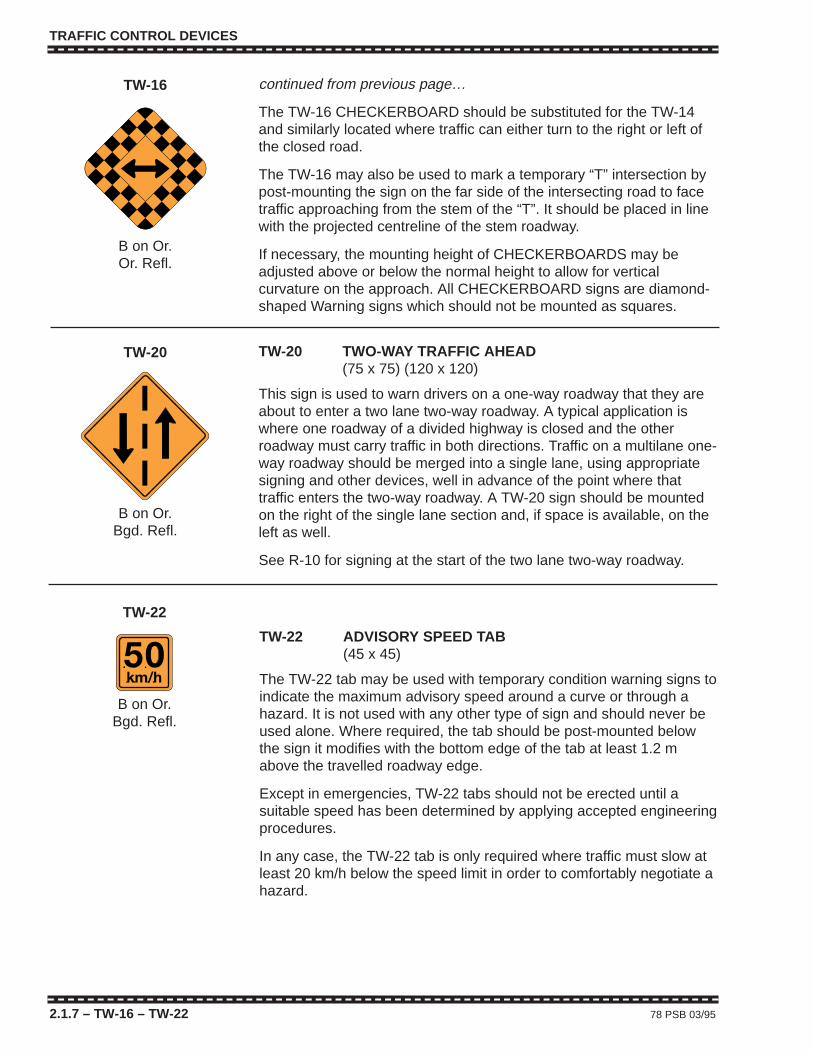
TRAFFIC CONTROL DEVICES
2.1.7 – TW-16 – TW-22 78 PSB 03/95
TW-22 ADVISORY SPEED TAB(45 x 45)
The TW-22 tab may be used with temporary condition warning signs toindicate the maximum advisory speed around a curve or through ahazard. It is not used with any other type of sign and should never beused alone. Where required, the tab should be post-mounted belowthe sign it modifies with the bottom edge of the tab at least 1.2 mabove the travelled roadway edge.
Except in emergencies, TW-22 tabs should not be erected until asuitable speed has been determined by applying accepted engineeringprocedures.
In any case, the TW-22 tab is only required where traffic must slow atleast 20 km/h below the speed limit in order to comfortably negotiate ahazard.
TW-22
B on Or.Bgd. Refl.
continued from previous page…
The TW-16 CHECKERBOARD should be substituted for the TW-14and similarly located where traffic can either turn to the right or left ofthe closed road.
The TW-16 may also be used to mark a temporary “T” intersection bypost-mounting the sign on the far side of the intersecting road to facetraffic approaching from the stem of the “T”. It should be placed in linewith the projected centreline of the stem roadway.
If necessary, the mounting height of CHECKERBOARDS may beadjusted above or below the normal height to allow for verticalcurvature on the approach. All CHECKERBOARD signs are diamond-shaped Warning signs which should not be mounted as squares.
TW-16
B on Or.Or. Refl.
TW-20 TWO-WAY TRAFFIC AHEAD(75 x 75) (120 x 120)
This sign is used to warn drivers on a one-way roadway that they areabout to enter a two lane two-way roadway. A typical application iswhere one roadway of a divided highway is closed and the otherroadway must carry traffic in both directions. Traffic on a multilane one-way roadway should be merged into a single lane, using appropriatesigning and other devices, well in advance of the point where thattraffic enters the two-way roadway. A TW-20 sign should be mountedon the right of the single lane section and, if space is available, on theleft as well.
See R-10 for signing at the start of the two lane two-way roadway.
TW-20
B on Or.Bgd. Refl.
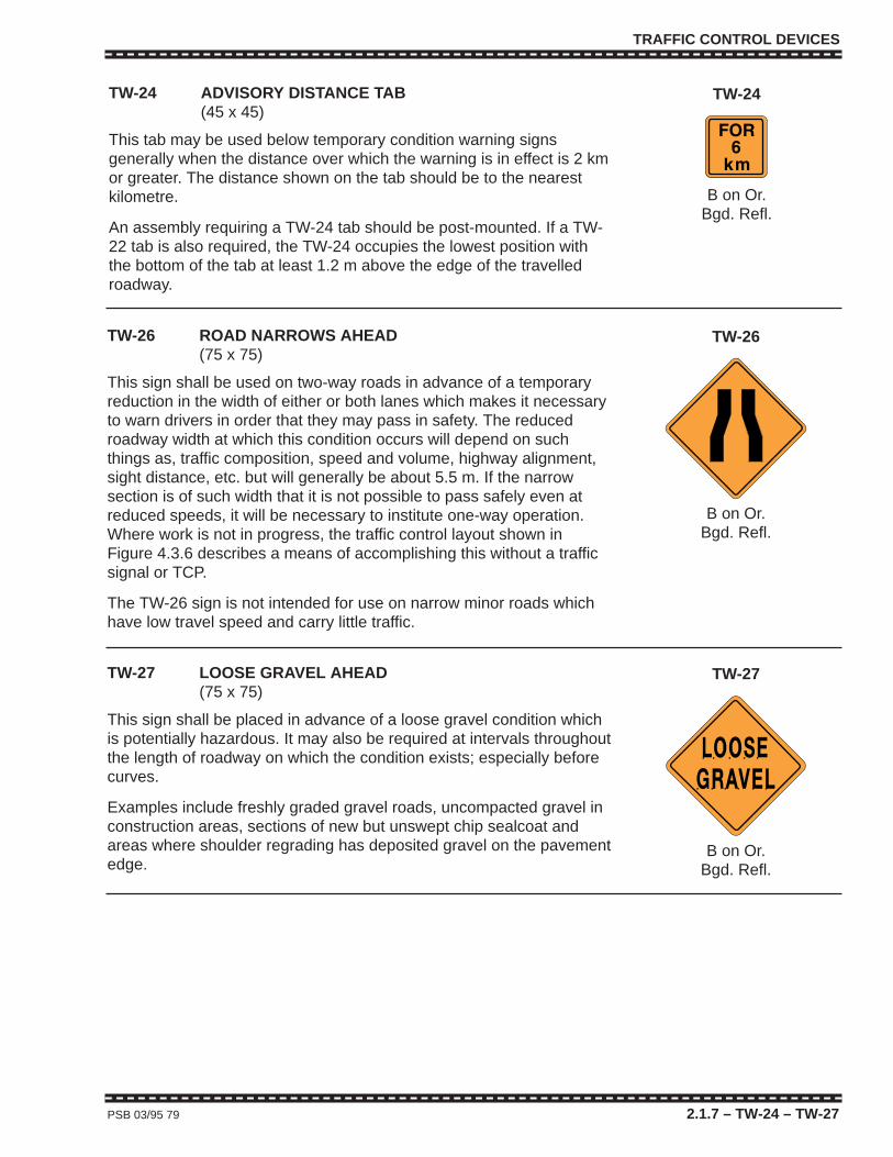
TRAFFIC CONTROL DEVICES
PSB 03/95 79 2.1.7 – TW-24 – TW-27
TW-24 ADVISORY DISTANCE TAB(45 x 45)
This tab may be used below temporary condition warning signsgenerally when the distance over which the warning is in effect is 2 kmor greater. The distance shown on the tab should be to the nearestkilometre.
An assembly requiring a TW-24 tab should be post-mounted. If a TW-22 tab is also required, the TW-24 occupies the lowest position withthe bottom of the tab at least 1.2 m above the edge of the travelledroadway.
TW-24
B on Or.Bgd. Refl.
TW-26 ROAD NARROWS AHEAD(75 x 75)
This sign shall be used on two-way roads in advance of a temporaryreduction in the width of either or both lanes which makes it necessaryto warn drivers in order that they may pass in safety. The reducedroadway width at which this condition occurs will depend on suchthings as, traffic composition, speed and volume, highway alignment,sight distance, etc. but will generally be about 5.5 m. If the narrowsection is of such width that it is not possible to pass safely even atreduced speeds, it will be necessary to institute one-way operation.Where work is not in progress, the traffic control layout shown inFigure 4.3.6 describes a means of accomplishing this without a trafficsignal or TCP.
The TW-26 sign is not intended for use on narrow minor roads whichhave low travel speed and carry little traffic.
TW-26
B on Or.Bgd. Refl.
TW-27 LOOSE GRAVEL AHEAD(75 x 75)
This sign shall be placed in advance of a loose gravel condition whichis potentially hazardous. It may also be required at intervals throughoutthe length of roadway on which the condition exists; especially beforecurves.
Examples include freshly graded gravel roads, uncompacted gravel inconstruction areas, sections of new but unswept chip sealcoat andareas where shoulder regrading has deposited gravel on the pavementedge.
TW-27
B on Or.Bgd. Refl.
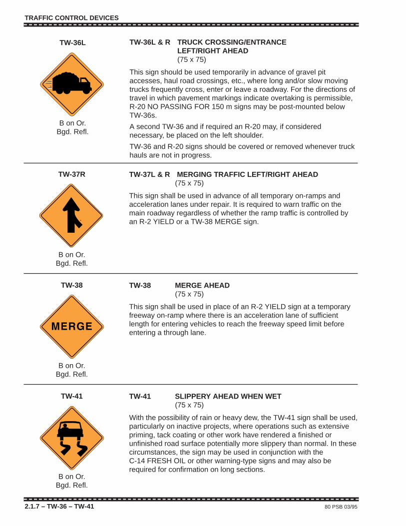
TRAFFIC CONTROL DEVICES
2.1.7 – TW-36 – TW-41 80 PSB 03/95
TW-37L & R MERGING TRAFFIC LEFT/RIGHT AHEAD(75 x 75)
This sign shall be used in advance of all temporary on-ramps andacceleration lanes under repair. It is required to warn traffic on themain roadway regardless of whether the ramp traffic is controlled byan R-2 YIELD or a TW-38 MERGE sign.
TW-37R
B on Or.Bgd. Refl.
TW-38 MERGE AHEAD(75 x 75)
This sign shall be used in place of an R-2 YIELD sign at a temporaryfreeway on-ramp where there is an acceleration lane of sufficientlength for entering vehicles to reach the freeway speed limit beforeentering a through lane.
TW-38
B on Or.Bgd. Refl.
TW-41 SLIPPERY AHEAD WHEN WET(75 x 75)
With the possibility of rain or heavy dew, the TW-41 sign shall be used,particularly on inactive projects, where operations such as extensivepriming, tack coating or other work have rendered a finished orunfinished road surface potentially more slippery than normal. In thesecircumstances, the sign may be used in conjunction with the C-14 FRESH OIL or other warning-type signs and may also berequired for confirmation on long sections.
TW-41
B on Or.Bgd. Refl.
TW-36L
B on Or.Bgd. Refl.
TW-36L & R TRUCK CROSSING/ENTRANCELEFT/RIGHT AHEAD(75 x 75)
This sign should be used temporarily in advance of gravel pitaccesses, haul road crossings, etc., where long and/or slow movingtrucks frequently cross, enter or leave a roadway. For the directions oftravel in which pavement markings indicate overtaking is permissible,R-20 NO PASSING FOR 150 m signs may be post-mounted belowTW-36s.
A second TW-36 and if required an R-20 may, if considerednecessary, be placed on the left shoulder.
TW-36 and R-20 signs should be covered or removed whenever truckhauls are not in progress.
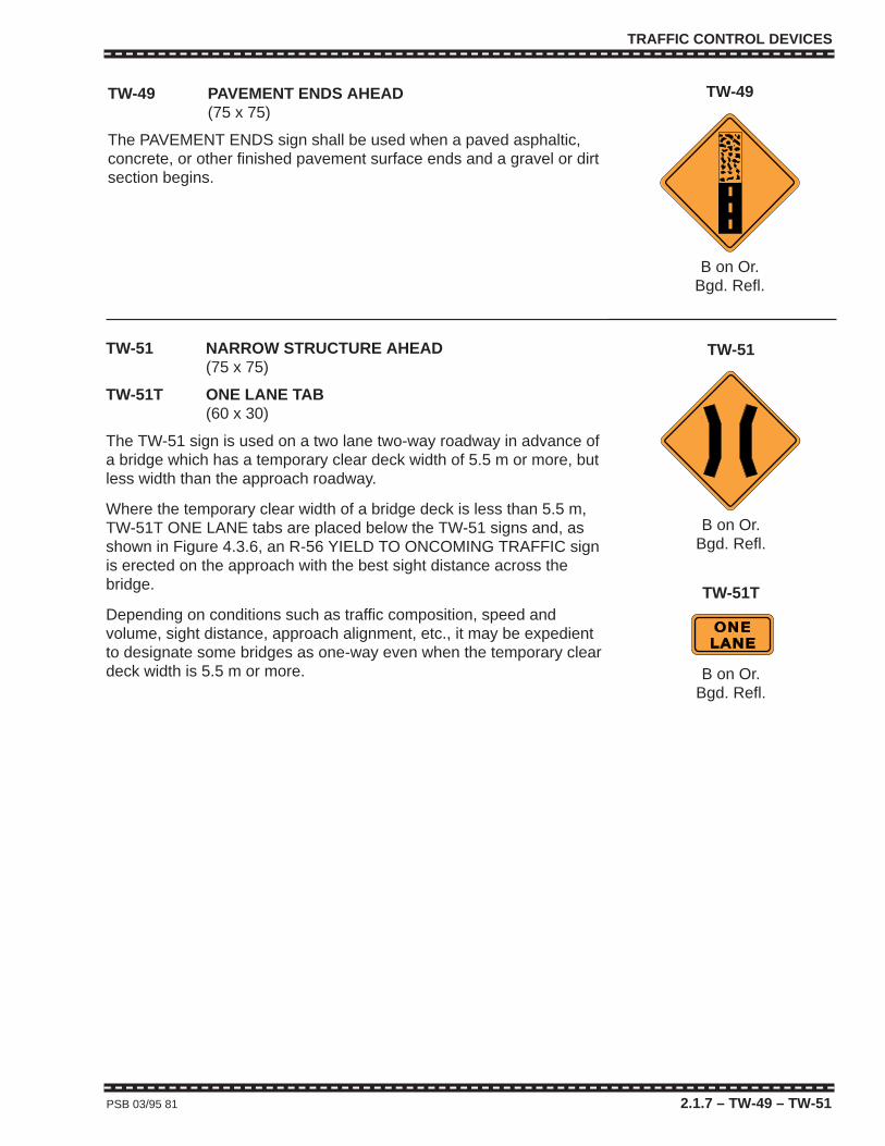
TRAFFIC CONTROL DEVICES
PSB 03/95 81 2.1.7 – TW-49 – TW-51
TW-51 NARROW STRUCTURE AHEAD(75 x 75)
TW-51T ONE LANE TAB(60 x 30)
The TW-51 sign is used on a two lane two-way roadway in advance ofa bridge which has a temporary clear deck width of 5.5 m or more, butless width than the approach roadway.
Where the temporary clear width of a bridge deck is less than 5.5 m,TW-51T ONE LANE tabs are placed below the TW-51 signs and, asshown in Figure 4.3.6, an R-56 YIELD TO ONCOMING TRAFFIC signis erected on the approach with the best sight distance across thebridge.
Depending on conditions such as traffic composition, speed andvolume, sight distance, approach alignment, etc., it may be expedientto designate some bridges as one-way even when the temporary cleardeck width is 5.5 m or more.
TW-51
B on Or.Bgd. Refl.
TW-51T
B on Or.Bgd. Refl.
TW-49 PAVEMENT ENDS AHEAD(75 x 75)
The PAVEMENT ENDS sign shall be used when a paved asphaltic,concrete, or other finished pavement surface ends and a gravel or dirtsection begins.
TW-49
B on Or.Bgd. Refl.
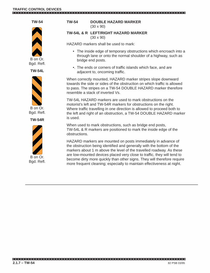
TRAFFIC CONTROL DEVICES
2.1.7 – TW-54 82 PSB 03/95
TW-54 DOUBLE HAZARD MARKER(30 x 90)
TW-54L & R LEFT/RIGHT HAZARD MARKER(30 x 90)
HAZARD markers shall be used to mark:
• The inside edge of temporary obstructions which encroach into athrough lane or onto the normal shoulder of a highway, such asbridge end posts.
•. The ends or corners of traffic islands which face, and areadjacent to, oncoming traffic.
When correctly mounted, HAZARD marker stripes slope downwardtowards the side or sides of the obstruction on which traffic is allowedto pass. The stripes on a TW-54 DOUBLE HAZARD marker thereforeresemble a stack of inverted Vs.
TW-54L HAZARD markers are used to mark obstructions on themotorist's left and TW-54R markers for obstructions on the right.Where traffic travelling in one direction is allowed to proceed both tothe left and right of an obstruction, a TW-54 DOUBLE HAZARD markeris used.
When used to mark obstructions, such as bridge end posts, TW-54L & R markers are positioned to mark the inside edge of theobstructions.
HAZARD markers are mounted on posts immediately in advance ofthe obstruction being identified and generally with the bottom of themarkers about 1 m above the level of the travelled roadway. As theseare low-mounted devices placed very close to traffic, they will tend tobecome dirty more quickly than other signs. They will therefore requiremore frequent cleaning; especially to maintain effectiveness at night.
TW-54
B on Or.Bgd. Refl.
TW-54L
B on Or.Bgd. Refl.
TW-54R
B on Or.Bgd. Refl.
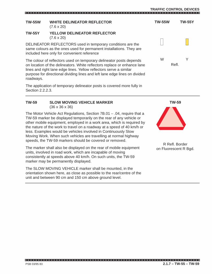
TRAFFIC CONTROL DEVICES
PSB 03/95 83 2.1.7 – TW-55 – TW-59
TW-59 SLOW MOVING VEHICLE MARKER(36 x 36 x 36)
The Motor Vehicle Act Regulations, Section 7B.01 – .04, require that aTW-59 marker be displayed temporarily on the rear of any vehicle orother mobile equipment, employed in a work area, which is required bythe nature of the work to travel on a roadway at a speed of 40 km/h orless. Examples would be vehicles involved in Continuously SlowMoving Work. When such vehicles are travelling at normal highwayspeeds, the TW-59 markers should be covered or removed.
The marker shall also be displayed on the rear of mobile equipmentunits, involved in road work, which are incapable of movingconsistently at speeds above 40 km/h. On such units, the TW-59marker may be permanently displayed.
The SLOW MOVING VEHICLE marker shall be mounted, in theorientation shown here, as close as possible to the rear/centre of theunit and between 90 cm and 150 cm above ground level.
TW-59
R Refl. Borderon Fluorescent R Bgd.
TW-55W
W
TW-55Y
Y
TW-55W WHITE DELINEATOR REFLECTOR(7.6 x 20)
TW-55Y YELLOW DELINEATOR REFLECTOR(7.6 x 20)
DELINEATOR REFLECTORS used in temporary conditions are thesame colours as the ones used for permanent installations. They areincluded here only for convenient reference
The colour of reflectors used on temporary delineator posts dependson location of the delineators. White reflectors replace or enhance lanelines and right lane edge lines. Yellow reflectors serve a similarpurpose for directional dividing lines and left lane edge lines on dividedroadways.
The application of temporary delineator posts is covered more fully inSection 2.2.2.3.
Refl.
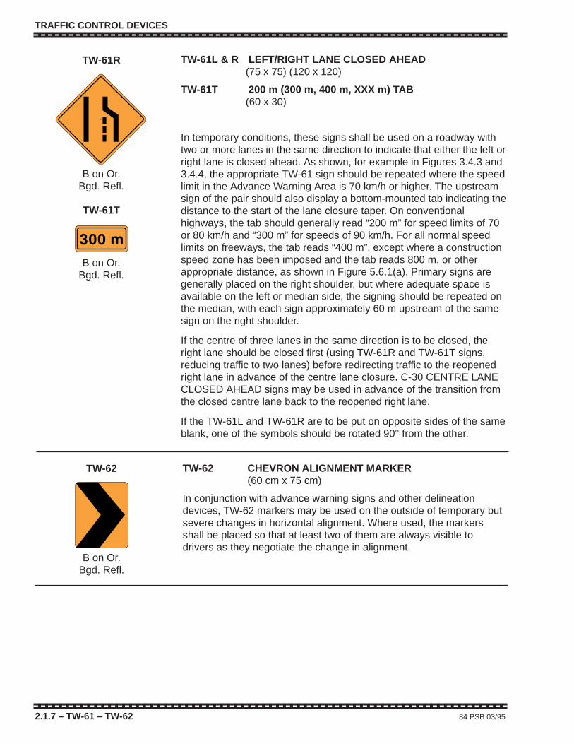
TRAFFIC CONTROL DEVICES
2.1.7 – TW-61 – TW-62 84 PSB 03/95
TW-62 CHEVRON ALIGNMENT MARKER(60 cm x 75 cm)
In conjunction with advance warning signs and other delineationdevices, TW-62 markers may be used on the outside of temporary butsevere changes in horizontal alignment. Where used, the markersshall be placed so that at least two of them are always visible todrivers as they negotiate the change in alignment.
TW-62
B on Or.Bgd. Refl.
TW-61L & R LEFT/RIGHT LANE CLOSED AHEAD(75 x 75) (120 x 120)
TW-61T 200 m (300 m, 400 m, XXX m) TAB(60 x 30)
In temporary conditions, these signs shall be used on a roadway withtwo or more lanes in the same direction to indicate that either the left orright lane is closed ahead. As shown, for example in Figures 3.4.3 and3.4.4, the appropriate TW-61 sign should be repeated where the speedlimit in the Advance Warning Area is 70 km/h or higher. The upstreamsign of the pair should also display a bottom-mounted tab indicating thedistance to the start of the lane closure taper. On conventionalhighways, the tab should generally read “200 m” for speed limits of 70or 80 km/h and “300 m” for speeds of 90 km/h. For all normal speedlimits on freeways, the tab reads “400 m”, except where a constructionspeed zone has been imposed and the tab reads 800 m, or otherappropriate distance, as shown in Figure 5.6.1(a). Primary signs aregenerally placed on the right shoulder, but where adequate space isavailable on the left or median side, the signing should be repeated onthe median, with each sign approximately 60 m upstream of the samesign on the right shoulder.
If the centre of three lanes in the same direction is to be closed, theright lane should be closed first (using TW-61R and TW-61T signs,reducing traffic to two lanes) before redirecting traffic to the reopenedright lane in advance of the centre lane closure. C-30 CENTRE LANECLOSED AHEAD signs may be used in advance of the transition fromthe closed centre lane back to the reopened right lane.
If the TW-61L and TW-61R are to be put on opposite sides of the sameblank, one of the symbols should be rotated 90° from the other.
TW-61R
B on Or.Bgd. Refl.
TW-61T
B on Or.Bgd. Refl.

TRAFFIC CONTROL DEVICES
2.1.8 LIST OF REGULATORY (R) SIGNSSign Message Minimum Shape MUTCDC
Number or Title Size(s) Number
R-1 Stop 60 x 60 Oct. RA-1
R-1T 4-Way (3-Way) Tab 40 x 20 Rect. RA-1T
R-2 Yield (Sy.) 75/75/75 Tri. RA-2
R-3 Maximum __ km/h Ahead 60 x 75 Rect. RB-590 x 120
R-4 Maximum __ km/h 60 x 75 Rect. RB-190 x 120 RB-1
R-10 Two-way Traffic (Sy.) 60 x 75 Rect. RB-24
R-12 Road Closed 75 x 60 Rect. –
R-12T Local Traffic Only 75 x 30 Rect. –
R-14L & R Keep Left/Right (Sy.) 60 x 75 Rect. RB-25L/R
R-15L & R No Left/Right Turn (Sy.) 60 x 60 Sq. RB-12/11
R-18 Turn (Sy.) 60 x 60 Sq. –
R-20 No Passing for 150 m 60 x 45 Rect. –
R-22 Do Not Pass (Sy.) 60 x 60 Sq. RB-31
R-23 Passing Permitted(Sy.) 60 x 60 Sq. FB-32
R-33L & R This Lane Turn Left/Right 75 x 75 Sq. RB-41L/R(Sy.)
R-35L & R Stop Line Left/Right 60 x 75 Rect. RC-4L/R
R-56 Yield to Oncoming Traffic 90 x 120 Rect. –
R-125 Right Lane Must Turn Right 60 x 75 Rect –
Regulatory signs are the same for both temporary and permanent conditions. The above list containsthe Regulatory signs most commonly required for temporary work zones and the following pagesprovide some usage details for the individual signs. Other Regulatory signs which may be applicableare contained in the “British Columbia Manual of Standard Traffic Signs” or the “Manual of UniformTraffic Control Devices for Canada”.
Regulatory signs in the “R” category shall not be installed in work zones unless they are specificallycalled for in an approved Traffic Control Plan or unless otherwise approved by the road authority.
PSB 3/95 85 2.1.8

TRAFFIC CONTROL DEVICES
2.1.9 – R-1 – R-2 86 PSB 03/95
R-1 STOP(60 x 60)
R-1T 4-WAY (3-WAY) TAB(40 x 20)
R-1 signs may be required to assign right-of-way at temporaryintersections. They should be mounted at approximately the sameheight and in approximately the same position as for permanentinstallations.
Where all the approaches to a three or four leg temporary intersectionare controlled by STOP signs, they should be supplemented with R-1Ttabs indicating the number of approaches involved.
If a temporary STOP sign is not clearly visible for the safe stoppingdistance on the approach, a TW-11 STOP AHEAD sign is required. ATW-11 sign may also be needed if a STOP sign is to be installed at alocation where drivers wouldn’t normally expect to find one.
R-1
R on WFl. Refl.
R-1T
B on WBgd. Refl.
R-2 YIELD(30 x 30 x 30)
The YIELD sign may be used in temporary situations where the normalright-of-way rule cannot be applied safely but where a STOP signwould be overly restrictive. It shall not be used in place of an R-1 sign,however, at a right-angle intersection except for a free right turnmovement. The YIELD sign should be mounted at approximately thesame height and in approximately the same position as for permanentinstallations.
An example of usage for the R-2 sign would be at a temporary freewayon-ramp or other such one-way approach which merges with a throughroadway at a small angle. If an acceleration lane of sufficient lengthexists for on-ramp traffic to reach the through roadway speed limitbefore entering a through lane, a TW-38 MERGE sign is used in place
R-2
R on WFl. Refl.
2.1.9 WARRANTS FOR INDIVIDUAL (R) SIGNS

TRAFFIC CONTROL DEVICES
PSB 03/95 87 2.1.9 – R-3 – R-4
R-3 MAXIMUM __ km/h AHEAD(60 x 75) (90 x 120)
R-4 MAXIMUM __ km/h(60 x 75) (90 x 120)
Mounted above C-22 CONSTRUCTION SPEED ZONE tabs, R-3 andR-4 signs implement a mandatory lower construction speed zonewhere the need for (and speed limit level of) such a zone has beenestablished by the road authority.
The R-4 and C-22 assembly, showing the approved speed limit, marksthe start of the zone and is used for confirmation throughout. The R-3and C-22 combination, showing the same speed limit, should beplaced upstream of the zone start. Wherever possible on freeways andother one-way roadways, secondary assemblies should also bemounted on the median or left side.
A confirmatory R-4/C-22 assembly should be erected from 300 m to 600 m downstream of the zone start. Other confirmatory assembliesmay be required beyond all intervening intersections and on-rampsand at other intermediate locations on long uninterrupted ruralsections.
The 90 x 120 cm oversized versions of R-3 and R-4 signs aregenerally only used at the start of a construction speed zone where thereduction from the normal speed limit is 50 km/h or greater. OversizedR-3 and R-4 signs, however, may occasionally be used at otherconstruction speed zone starts if additional emphasis is required. Thestandard sized 60 x 75 cm R-4 sign may be used for confirmationwithin the zone.
The end of a construction speed zone is indicated by an R-4 signshowing the normal maximum speed. If the end of a constructionspeed zone is coincident with the end of a work zone, the R-4 ispreceded by a C-54 WORK ZONE ENDS sign.
R-3
B on WBgd. Refl.
R-4
B on WBgd. Refl.
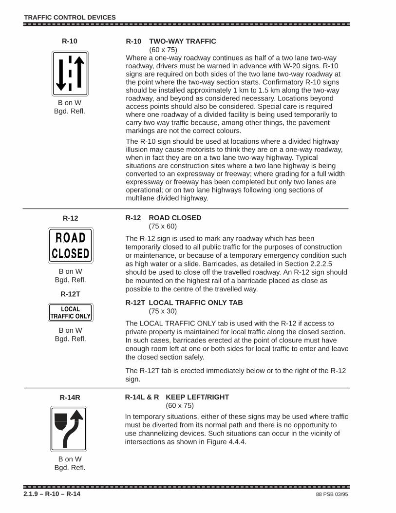
TRAFFIC CONTROL DEVICES
2.1.9 – R-10 – R-14 88 PSB 03/95
R-12 ROAD CLOSED(75 x 60)
The R-12 sign is used to mark any roadway which has beentemporarily closed to all public traffic for the purposes of constructionor maintenance, or because of a temporary emergency condition suchas high water or a slide. Barricades, as detailed in Section 2.2.2.5should be used to close off the travelled roadway. An R-12 sign shouldbe mounted on the highest rail of a barricade placed as close aspossible to the centre of the travelled way.
R-12T LOCAL TRAFFIC ONLY TAB(75 x 30)
The LOCAL TRAFFIC ONLY tab is used with the R-12 if access toprivate property is maintained for local traffic along the closed section.In such cases, barricades erected at the point of closure must haveenough room left at one or both sides for local traffic to enter and leavethe closed section safely.
The R-12T tab is erected immediately below or to the right of the R-12sign.
R-12
B on WBgd. Refl.
R-12T
B on WBgd. Refl.
R-10 TWO-WAY TRAFFIC(60 x 75)
Where a one-way roadway continues as half of a two lane two-wayroadway, drivers must be warned in advance with W-20 signs. R-10signs are required on both sides of the two lane two-way roadway atthe point where the two-way section starts. Confirmatory R-10 signsshould be installed approximately 1 km to 1.5 km along the two-wayroadway, and beyond as considered necessary. Locations beyondaccess points should also be considered. Special care is requiredwhere one roadway of a divided facility is being used temporarily tocarry two way traffic because, among other things, the pavementmarkings are not the correct colours.
The R-10 sign should be used at locations where a divided highwayillusion may cause motorists to think they are on a one-way roadway,when in fact they are on a two lane two-way highway. Typicalsituations are construction sites where a two lane highway is beingconverted to an expressway or freeway; where grading for a full widthexpressway or freeway has been completed but only two lanes areoperational; or on two lane highways following long sections ofmultilane divided highway.
R-10
B on WBgd. Refl.
R-14L & R KEEP LEFT/RIGHT(60 x 75)
In temporary situations, either of these signs may be used where trafficmust be diverted from its normal path and there is no opportunity touse channelizing devices. Such situations can occur in the vicinity ofintersections as shown in Figure 4.4.4.
R-14R
B on WBgd. Refl.
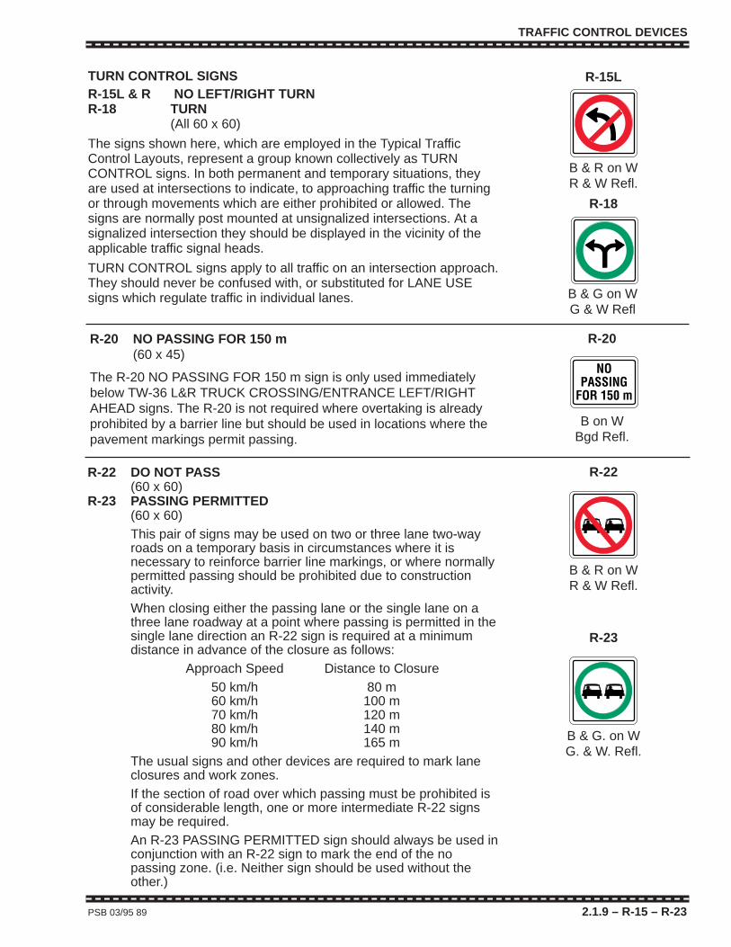
TRAFFIC CONTROL DEVICES
PSB 03/95 89 2.1.9 – R-15 – R-23
R-22 DO NOT PASS(60 x 60)
R-23 PASSING PERMITTED(60 x 60)This pair of signs may be used on two or three lane two-wayroads on a temporary basis in circumstances where it isnecessary to reinforce barrier line markings, or where normallypermitted passing should be prohibited due to constructionactivity.When closing either the passing lane or the single lane on athree lane roadway at a point where passing is permitted in thesingle lane direction an R-22 sign is required at a minimumdistance in advance of the closure as follows:
Approach Speed Distance to Closure50 km/h 80 m60 km/h 100 m70 km/h 120 m80 km/h 140 m90 km/h 165 m
The usual signs and other devices are required to mark laneclosures and work zones.If the section of road over which passing must be prohibited isof considerable length, one or more intermediate R-22 signsmay be required.An R-23 PASSING PERMITTED sign should always be used inconjunction with an R-22 sign to mark the end of the nopassing zone. (i.e. Neither sign should be used without theother.)
R-22
B & R on WR & W Refl.
R-23
B & G. on WG. & W. Refl.
R-20 NO PASSING FOR 150 m(60 x 45)
The R-20 NO PASSING FOR 150 m sign is only used immediatelybelow TW-36 L&R TRUCK CROSSING/ENTRANCE LEFT/RIGHTAHEAD signs. The R-20 is not required where overtaking is alreadyprohibited by a barrier line but should be used in locations where thepavement markings permit passing.
R-20
B on WBgd Refl.
TURN CONTROL SIGNSR-15L & R NO LEFT/RIGHT TURNR-18 TURN
(All 60 x 60)
The signs shown here, which are employed in the Typical TrafficControl Layouts, represent a group known collectively as TURNCONTROL signs. In both permanent and temporary situations, theyare used at intersections to indicate, to approaching traffic the turningor through movements which are either prohibited or allowed. Thesigns are normally post mounted at unsignalized intersections. At asignalized intersection they should be displayed in the vicinity of theapplicable traffic signal heads.
TURN CONTROL signs apply to all traffic on an intersection approach.They should never be confused with, or substituted for LANE USEsigns which regulate traffic in individual lanes.
R-15L
B & R on WR & W Refl.
R-18
B & G on WG & W Refl

TRAFFIC CONTROL DEVICES
2.1.9 – R-33 – R-125 90 PSB 03/95
R-35L & R STOP LINE LEFT/RIGHT(60 x 75)
These signs are only required at temporary traffic signal or temporarylane control signal installations where a stop line cannot be placed orwhere an installed stop line needs additional emphasis.
The R-35R sign is the one most commonly used and it shouldgenerally be post mounted at the intended stop location and to theright of approaching traffic. On a one-way roadway, or in othersituations where more than one lane approaches the temporary signalfrom the same direction, an R-35L sign should be post mounted on theleft side;if a secure location for it can be found.When properly located,the arrows on R-35 signs always point inward towards the travelledroadway.
R-35R
B on WBgd. Refl.
R-56 YIELD TO ONCOMING TRAFFIC(90 x 120)
The R-56 sign is used with temporary warning-type signs, such asC-24 SINGLE LANE TRAFFIC or TW-51/TW-51T ONE LANESTRUCTURE, to control a single lane traffic section on a roadwaywhich is principally or usually a two lane two-way facility. It must onlybe displayed for one direction and must only be used where adequatesight distance, low traffic volumes and low speeds render the use ofTCPs, temporary traffic signals, or temporary lane control signalsunnecessary.
The R-56 sign shall also be used on the rear of a work vehicleinvolved in Continuously Slow Moving Work on a two lane two-wayroadway.
R-56
B & R on WR & W Refl.
R-125 RIGHT LANE MUST TURN RIGHT(60 x 75)
This sign may be used instead of the R-33R THIS LANE TURN RIGHTsign if a suitable location cannot be found to display the latter.
R-125
B on WBgd. Refl.
LANE USE SIGNS
R-33L & R THIS LANE TURN LEFT/RIGHT(75 x 75)
The sign shown here, which is employed in the Typical Traffic ControlLayouts, is one of a group known collectively as LANE USE signs. Inboth permanent and temporary situations, LANE USE signs may beused to control traffic approaching intersections. Unlike TURNCONTROL signs, they are placed in advance of intersections and theirrequirements apply only to specific lanes.
For short duration operations, LANE USE signs may be post mounted.For long duration work, LANE USE signs should either be postmounted or preferably mounted over the centre of the lane or lanes towhich they apply.
R-33R
W on BW Refl.
OTHER DEVICES
2.2 OTHER DEVICES2.2.1 TEMPORARY PAVEMENT MARKINGS
Sometimes permanent pavement markings must be destroyed orcovered by work such as paving, sealcoating, milling, crack sealing,etc. Where it is not practical to replace the permanent markings thesame day, some form of temporary delineation must be provided.Under this condition every effort should be made, road and weatherconditions permitting, to install temporary road markings thesame day. If this cannot be done, some type of raisedchannelization devices must be installed. First priority should begiven to directional dividing lines and second priority to lane lines andother markings. If work is progressing rapidly it may be desirable toinstall temporary pavement markings periodically throughout the day.
Temporary markings may consist of paint with glass bead,preformed adhesive backed tape, road studs, “L” shaped flexiblereflectorized markers etc. A marking of a type which will necessitatepavement damage by its removal should not be used on a finalpavement lift.The “L” shaped flexible markers are the only practicalmarking for sealcoating work and milled pavement; attaching with nailsif necessary on rough surfaces. Where for any reason temporarymarkings cannot be installed, temporary delineation devices should beused, at least to separate traffic travelling in opposite directions,although this may reduce passing opportunities.
Particular care should be taken where crack sealing on centrelinemay destroy the effectiveness of a barrier line. Use of R-22 and R-23signs may be considered in such cases.
Use of R-22 and R-23 signs may also be considered in a situationwhere it is felt that the no passing intention of double yellow temporarydirectional dividing line may not be sufficiently clear or theconsequence of a misunderstanding may be particularly serious.
If it is evident that conflict between permanent and temporarypavement markings or channelizing devices will confuse drivers, thepermanent markings will have to be removed. It should be kept in mindthat on some pavement surfaces permanent markings which havebeen effectively removed for dry daylight conditions may under wetconditions still appear to be in place. If this condition is anticipated orfound to exist, use of raised pavement markers or special delineationmay be required.
Whenever possible, temporary pavement markings should be inplace before traffic is moved from its previous path. If this is notfeasible, for example; with frequent redirection of traffic paths or wheretraffic must proceed through surfacing projects without the aid of TCPsor pilot cars, temporary delineation may be accomplished with conesor other channelizing devices.
On sand or gravel (chip) sealcoated surfaces, temporary orpermanent pavement markings should be installed as soon as theexcess sand or gravel has been removed.
PSB 03/95 91 2.2 – 2.2.1
OTHER DEVICES
2.2.1 TEMPORARY PAVEMENT MARKINGS (continued)
Where the normal limit is 70 km/h or greater and temporarymeasures as previously described are not possible or may not, bythemselves, be considered to provide adequate safety, it may benecessary to establish a construction speed zone. See Section 1.4.6for application of construction speed zones. A construction speed zonemay be required 24 hours a day, only while work is in progress, or onlywhen work is not in progress. An example of where it may only berequired when work is not in progress would be a site controlled duringconstruction hours by TCPs or pilot cars.
Temporary directional dividing lines, and lane lines formed with paintor plastic should be approximately 10 cm wide, at least 50 cm long,and separated by gaps not exceeding 8 m. Two yellow markings sideby side and approximately 10 cm apart are required wherever passingis prohibited in either direction. Stop lines should be approximately 30cm wide and pavement arrows at least one third the size of standardarrows.
Raised plastic devices such as reflective road studs or “L” shapedflexible reflectorized markers, etc., may be used to supplement or beused in place of temporary pavement markings. Where usedsupplementally, these raised devices should be installed immediatelydownstream of every fourth 50 cm dash or approximately 26 m apart.When used without temporary pavement markings, they should alsobe installed approximately every 26 m. Regardless of the abovemaximum spacing, raised markers should be installed frequentlyenough so that a minimum of four individual markers of four pairs ofside-by-side markers are visible from any given point. In mostcircumstances, these devices are more effective than temporarymarking tape; particularly, through changes in horizontal or verticalalignment, in areas where speeds and/or volumes are high and whereadverse weather conditions (such as fog or rain) might reasonably beexpected in hours of darkness.
Temporary pavement markings and raised marking devices must bereflectorized and display the same colour by night as by day. Theymust also be the same colour as the permanent markings which theyreplace.
2.2.2 CHANNELIZING DEVICES – GENERALChannelizing devices are used to direct traffic away from, through or
around a work area and may also be employed to separate traffictravelling in opposite directions.
Several types of channelizing devices, such as barriers, barricades,temporary delineator posts, traffic cones, tubular markers and flexibledrums, are detailed below. In case they are struck by errant vehicles,the devices themselves must be less hazardous than the hazards theymark.
The minimum reflectorization requirements are specified in thissection for channelizing devices used at night.
2.2.1 – 2.2.2 92 PSB 03/95
OTHER DEVICES
2.2.2 CHANNELING DEVICES – GENERAL (continued)
Because they are easily knocked down, displaced or blown over,some channelizing devices need extra weight to keep them in place.Sand bags or lead impregnated plastic collars may be used but solidmaterials, such as rock, concrete, etc., are not acceptable for thispurpose. Extra weights should be placed at the base of devices toprovide maximum stability and to avoid the weights becomingprojectiles in the event of a collision. Extra weights should be placed ina way that does not reduce the effectiveness of devices.
PSB 03/95 93 2.2.2

2.2.2.1 Channelizing Devices at a Glance
Class 1ABarricadeW on Or.Fl. Refl.
Class 1BarricadeOr. on BOr. Refl.
Class 2BarricadeOr. on BOr. Refl.
Class 3BarricadeOr. on BOr. Refl.
15 cm ConeType A
45 cm ConeType B
70 cm ConeType C
100 cm Tubular MarkerType D
Flexible Drum Temporary Delineator Posts
White Yellow
OTHER DEVICES
2.2.2.1 94 PSB 03/95
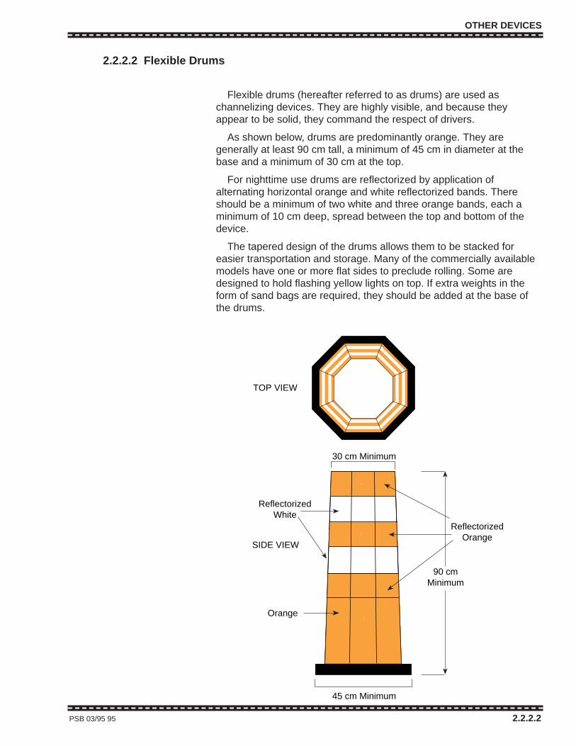
OTHER DEVICES
2.2.2.2 Flexible Drums
Flexible drums (hereafter referred to as drums) are used aschannelizing devices. They are highly visible, and because theyappear to be solid, they command the respect of drivers.
As shown below, drums are predominantly orange. They aregenerally at least 90 cm tall, a minimum of 45 cm in diameter at thebase and a minimum of 30 cm at the top.
For nighttime use drums are reflectorized by application ofalternating horizontal orange and white reflectorized bands. Thereshould be a minimum of two white and three orange bands, each aminimum of 10 cm deep, spread between the top and bottom of thedevice.
The tapered design of the drums allows them to be stacked foreasier transportation and storage. Many of the commercially availablemodels have one or more flat sides to preclude rolling. Some aredesigned to hold flashing yellow lights on top. If extra weights in theform of sand bags are required, they should be added at the base ofthe drums.
PSB 03/95 95 2.2.2.2
TOP VIEW
SIDE VIEW
30 cm Minimum
90 cmMinimum
45 cm Minimum
Orange
ReflectorizedWhite
ReflectorizedOrange

OTHER DEVICES
2.2.2.3 Temporary Delineator Posts (TDPs)
Temporary delineator posts (TDPs) are used to channelize traffic, toseparate opposing lanes, to separate lanes of same direction trafficand for outlining work areas. Particularly at night, their use for thesepurposes may be preferred over Type B or C traffic cones, due to thenarrow design and the additional height.
TDPs are generally constructed as shown above with post tops 1.2 m above the edge of the travelled roadway. They may be of theportable type, held down by sandbags placed on the base supports orthey may be dug or driven into a roadway or shoulder provided that thestandard display height is maintained. As with other channelizingdevices, several TDPs should be visible at any one time in anyapplication. Spacing in tapers should therefore be as shown for conesin Tables A and B.
Temporary delineator posts display TW-55 Reflectors of the samecolour as the pavement markings they supplement or replace. That is,TW-55W (White) Reflectors are used for right lane edges and (samedirection) lane lines and TW-55Y (Yellow) Reflectors separateopposing lanes of traffic and mark the left edge of one-way roadways.Where TDPs separate opposing lanes of traffic, they have yellowreflectors on both approach faces.
2.2.2.3 96 PSB 03/95
White
Black 5 cm
5 cm
10 cm Minimum
60 cm
Delineator Reflectors(7.6 x 20 cm)
TW-55W (White)TW-55Y (Yellow)
5 cmMinimum
120 cm
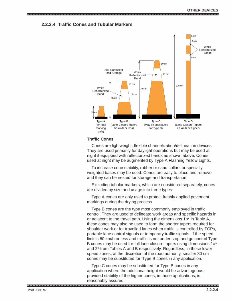
OTHER DEVICES
2.2.2.4 Traffic Cones and Tubular Markers
Traffic Cones
Cones are lightweight, flexible channelization/delineation devices.They are used primarily for daylight operations but may be used atnight if equipped with reflectorized bands as shown above. Conesused at night may be augmented by Type A Flashing Yellow Lights.
To increase cone stability, rubber or sand collars or speciallyweighted bases may be used. Cones are easy to place and removeand they can be nested for storage and transportation.
Excluding tubular markers, which are considered separately, conesare divided by size and usage into three types:
Type A cones are only used to protect freshly applied pavementmarkings during the drying process.
Type B cones are the type most commonly employed in trafficcontrol. They are used to delineate work areas and specific hazards inor adjacent to the travel path. Using the dimensions 1b* in Table A,these cones may also be used to form the shorter tapers required forshoulder work or for travelled lanes when traffic is controlled by TCPs,portable lane control signals or temporary traffic signals. If the speedlimit is 60 km/h or less and traffic is not under stop and go control TypeB cones may be used for full lane closure tapers using dimensions 1a*and 2* from Tables A and B respectively. Regardless, in these lowerspeed zones, at the discretion of the road authority, smaller 30 cmcones may be substituted for 'Type B cones in any application.
Type C cones may be substituted for Type B cones in anyapplication where the additional height would be advantageous;provided stability of the higher cones, in those applications, isreasonably assured.
PSB 03/95 97 2.2.2.4
15 cm
45 cm
70 cm
15 cm
10 cm
15 cm
100 cm
All FluorescentRed–Orange
5 cm
8 cm
10 cm
8 cm
Type B(Lane Closure Tapers
60 km/h or less)
Type C(May be substituted
for Type B)
Type A(for roadmarking
only)
WhiteReflectorized
Band
WhiteReflectorized
Bands
WhiteReflectorized
Band
Type D(Lane Closure Tapers
70 km/h or higher)
OTHER DEVICES
2.2.2.4 TRAFFIC CONES & TUBULAR MARKERS (continued)
As traffic cones cause little or no damage when hit, drivers tend notto respect them as much as other delineation and channelizationdevices. Consequently, even weighted cones will need to be checkedmore often for correct positioning.
Tubular Markers
Tubular markers are similar to cones in that they are lightweight andeasy to place and remove. They may be set in special weighted basesor fastened directly to the pavement. Due to their increased height andnarrow width, tubular markers are particularly suited to delineatingtraffic lanes or separating two-way traffic for short duration work. Forconvenience, tubular markers are included in the cone series as Type D.
Tubular markers should be at least 100 cm high. They are principallydaytime devices but may be used at night if equipped with reflectivebands as shown above.
Tubular markers may replace Type B and Type C cones in any oftheir applications; provided reasonable stability is assured. They shallbe used in place of the lower cones, however, for full lane closuretapers where the speed limit is 70 km/h or higher and traffic is notunder stop and go control.
Above are the minimum standards with respect to size,reflectorization and usage for traffic cones and tubular markers. Largeror higher versions of the devices may always be used in place ofsmaller ones provided the oversized applications are consistent.
Secondary Devices
Where required to increase visibility, secondary devices made oflightweight materials and approved by the road authority may beattached to the tops of devices contained in this section, provided theadditions do not significantly decrease stability of the primary devicesor increase their hazard potential.
Reflective Sheeting for Cones and Markers
The road authority may specify the level of reflective sheeting thatshall be used on traffic cones, tubular markers and temporarydelineators, but as a minimum all white sheeting on these devices shallbe “enclosed lens sheeting” (engineering grade).
All white sign sheeting material for traffic cones, tubular markers andtemporary delineators used for works on provincial highways mustmeet CGSB Standard 62-GP-11M. Level 1, “encapsulated lensreflective sheeting (“High Intensity”) unless otherwise specified by theChief Highway Engineer.
2.2.2.4 98 PSB 03/95

OTHER DEVICES
2.2.2.5 Barricades
Barricades are highly visible, relatively frangible warning deviceswhich are used, in a variety of circumstances, to mark areas into whichmost public traffic is not intended to proceed. Barricades, not to beconfused with temporary concrete barriers, are categorized as Class1A, 1, 2 and 3; each with their own particular applications. Illustrationsof typical barricades are shown in the following diagrams:
PSB 03/95 99 2.2.2.5
CLASS 1 A
CLASS 1
TOP VIEW
RIGHT EQUIVALENT
LEFT EQUIVALENT
5 cm x 10 cm
25 cm
W= 1.8 m Minimum7.5 cm
5 cm
1.2 m
1.2 m
END VIEW
5 cm x 20 cm or5 cm x 25 cmRefl. Or.
60 cm Minimum
20 cmMinimum
15 cmMinimum
Type A or BFlashing Yellow LIght
Refl.Orange
Refl.White
60 cmTypical
Right Equivalent(Left Equivalent on
other side)
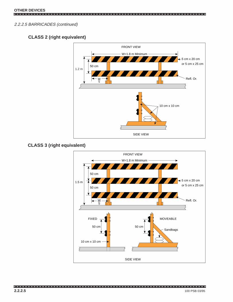
OTHER DEVICES
2.2.2.5 BARRICADES (continued)
2.2.2.5 100 PSB 03/95
CLASS 2 (right equivalent)
CLASS 3 (right equivalent)
50 cm
5 cm x 20 cm
or 5 cm x 25 cm
10 cm x 10 cm
W=1.8 m Minimum
FRONT VIEW
1.2 m
SIDE VIEW
W5
Refl. Or.
MOVEABLE
Sandbags
FIXED
W5
50 cm
50 cm
1.5 m 5 cm x 20 cm
or 5 cm x 25 cm
50 cm50 cm
10 cm x 10 cm
W=1.8 m Minimum
FRONT VIEW
SIDE VIEW
Refl. Or.
1.2 m
OTHER DEVICES
2.2.2.5 BARRICADES (continued)
Barricades are divided into Classes 1A, 1, 2 and 3. The numeralsindicate the number of rails involved. Class 1 and 1A barricades aregenerally used for marking temporary hazards, delineating areastemporarily closed to traffic and for channelizing vehicles andpedestrians. Class 2 barricades are used for temporary closure ofroads of moderate importance and for closures and channelizationwhich, while temporary, is of several days duration. Class 3 barricadesare used for permanent closures and more significant temporaryclosures. If required, a higher class of barricade can be substituted fora lower one in most applications.
C-3, C-3L and C-3R BARRICADE REFLECTORS, detailed inSection 2.1.5, are generally used to make the rails for Class 1, 2 and 3barricades. For Class 1 and 1A barricades, the left and rightequivalents are often made on the opposite sides of the same rail sothat both are readily available at the same location. When barricadesare used for channelization, reflectors should slope downward towardsthe side on which traffic is to pass. For a total closure the reflectorsshould slope down towards the centre of the barricade. If Class 1 or 1Abarricades are used to separate opposing lanes of traffic, both sides ofthe rails should be made as left equivalents.
Class 1, 2 and 3 barricades can also be used as sign supports.Where warranted such signs as R-12 ROAD CLOSED, R-12T LOCALTRAFFIC ONLY and C-5L or R DETOUR markers may be attached tothe (highest) barricade rail.
Class 1A barricades are normally provided with Type A flashingyellow lights for use at night. All barricades, however, can be equippedwith Type A or B flashing or Type C steady burn yellow lights to warnof individual hazards, road closures, lane closure tapers, transitionsand closed off areas. When used in a series, Type A and B flashingyellow lights should not normally be mixed.
Where required, the stability of portable barricades can be enhancedwith the use of sandbags provided they are placed on or close to thebarricade bases.
PSB 03/95 101 2.2.2.5

OTHER DEVICES
2.2.2.6 Concrete Barriers
The terms “barrier” and “barricade” are often confused. Barricades, asdiscussed previously, are relatively frangible devices, normally placedat or near right-angles to approaching traffic, that provide visualidentification of hazardous locations or delineate travel paths and arerelatively forgiving of errant vehicles. On the other hand, barriers arenormally placed parallel or near parallel to approaching traffic. Theyare solid, continuous installations designed to deflect errant vehicles,at a small angle, that might otherwise enter a closed or hazardousarea.
Individual, unconnected sections of barrier are generally not used dueto the number of exposed ends and gaps through which vehicles couldpass. If it is necessary to have a break in a barrier installation, foraccess to a work area, then the downstream portion should be offsetlaterally away from the travelled path and overlapped by extending theupstream portion downstream of the gap. Unlike barricades, barriersare not normally installed at or near right-angles in higher speed zoneswhere they could be severely impacted by errant vehicles.
The design of sectional, precast, concrete barriers used totemporarily separate or delineate traffic is the same as for permanentbarrier installations.
Where required, concrete barriers are most commonly used in longduration (but still temporary) work zones to:
• Protect workers.
• Separate motorists from potentially hazardous objects and areasin work zones.
2.2.2.6 102 PSB 03/95

OTHER DEVICES
2.2.2.6 CONCRETE BARRIERS (continued)
• Separate opposing lanes of traffic where barricades or otherdelineation devices are not considered adequate.
• Reinforce other channelizing devices in lane closure tapers orother areas where public traffic cannot be allowed to enter.
Barriers are designed to contain and redirect errant vehicles. Theyare generally precast in sections with connecting devices strongenough to ensure that installations act as smooth continuous barriers.For some applications, it may be necessary to anchor the barriersections to prevent lateral movement if hit by vehicles. This can beaccomplished with drift pins or anchor bolts firmly attached to the roadsurface.
Barriers used as channelizing devices should be light in colour, toaid visibility, and equipped with delineators/ barricade reflectors, barrierreflectors and/or Type A, B or C yellow lights. If room is available, asolid lane edge line may be installed to indicate shying distance. Whenused in lane closure situations, as well as the above requirements,barriers shall be preceded by devices placed for a standard laneclosure taper.
If the exposed approach end of a barrier cannot be flared away fromthe intended travel path, it should be protected with attenuation (crashcushion) devices. Connections to any existing barriers or guardrailsshould be smooth and should not create weak points.
The details for barrier installations should be contained in trafficcontrol plans. Further information on locating and designing temporaryconcrete barrier installations is available in the Ministry’s DesignManual.
PSB 03/95 103 2.2.2.6
OTHER DEVICES
2.2.3 LIGHTING DEVICES
2.2.3.1 Yellow Warning LightsOther than warning lights on vehicles, flashing arrow boards andoverhead flashing beacons, which are all considered later, thefollowing three types of yellow lights are commonly used for warning intemporary conditions:
Type A. (Low Intensity Flashing Yellow Lights).
These lights are portable, 6 V battery-operated, normally with aphoto-electric switch and with two lenses to provide bi-directional light.They are often used at night to supplement warning signs andchannelizing or taper devices such as barriers, barricades (particularlyClass 1A) and flexible drums. They may also be used for markingspecific hazards and for outlining long duration work areas. Type Alights should be visible for at least 900 m under clear night timeconditions. All types of battery-operated flashing yellow lights shouldbe attached firmly to the devices supplemented so as not to fly loose inthe event of a collision.
Type A. Modified (Medium Intensity Flashing Yellow Lights).
Modified Type A lights have been re-wired for 12 V operation; mainlyfor daytime use. As these units have two 6 V batteries wired in series,they will consume more power than Type A’s and batteries will requiremore frequent checking. They have manual switches, one reflector andone lens to provide uni-directional light. They should be visible for atleast 300 m in normal daylight conditions. They can be used in place ofType B lights, or flags, for daytime work; particularly in conjunction withC-38 and C-41 signs on portable stands.
Type B. (High Intensity Flashing Yellow Lights).
These lights are also intended for daytime use but, as they arepowered by 12 V vehicle-sized batteries, they are quite heavy,compared to Modified Type A’s, and not generally suited for someapplications such as top-mounting on portable sign stands. They alsohave manual switches, one reflector and one lens to provide uni-directional light. They are best suited for use on or with heavierchannelization devices such as Class 2 or 3 barricades or concretebarriers or they may be used to mark obstructions. Type B lightsshould be visible for at least 300 m in normal daylight conditions. Flagsmay be substituted for Type B (or Modified Type A) lights in daytimeapplications.
Type B(or Modified Type A) lights may occasionally be required atnight, in place of Type A lights, if additional emphasis is required.When used in a series, Type A, Modified Type A and Type B flashingyellow lights should not normally be mixed.
Type C. (Steady Burn Low Wattage Yellow Lights).
These lights are 110 volt powered and are displayed in strings. Theymay be used at night to supplement channelization or lane closuretaper devices. They may also be used to delineate a work area or torun along the edge of a closed lane or shoulder; particularly wherefloodlighting or normal street lighting is also in place. Steady burnyellow lights should be visible for at least 900 m under normal night-time conditions.
2.2.3 – 2.2.3.1 104 PSB 03/95

OTHER DEVICES
2.2.3.2 Flashing Vehicle LightsAs potential hazards to public traffic, all work, buffer and shadow
vehicles stationed in or near travelled lanes must be equipped withflashing yellow lights. As a minimum, these should consist of standardvehicle equipment of 4-way (emergency) flashers and a 360 degreerotating yellow light. Although this latter device does not actually flash,it appears to do so when viewed from any given point.
The 360 degree flashing yellow lights (FYLs) and 4-way flashersshould be employed in a work area whenever a vehicle is sopositioned that it could influence public traffic.
2.2.3.3 Flashing Arrow Boards (FABs)
Flashing arrow boards (FABs) are traffic signs with a matrix of lightswhich can be flashed in unison or in sequential displays. They are veryeffective both day and night. FAB is possibly a misnomer for thisdevice as it can show both directional arrows and non-directionaldisplays. The FAB term is used for convenience.
The main purpose of FABs, on multilane roadways, is to direct trafficfrom a closed lane to another available lane; using appropriate arrowindications. In this mode, they can be used for static or movingoperations. But FABs can also be used without directional indication inplace of or in addition to 4-way flashers and 360s, to give a morevisible warning display that work is in progress.
FABs can be mounted on trucks or trailers for both stationary andmoving operations.
There are two kinds of FABs; flashing and sequencing. Both kindshave three basic operating modes:
• Left arrow.
• Right arrow.
• Warning mode with four or more lamps arranged in a patternwhich does not indicate a direction.
Normally only one arrow head is displayed at a time.
Sequencing arrow panels have several arrowheads that flash in aseries, directing traffic to the right or left.
PSB 03/95 105 2.2.3.2 – 2.2.3.3
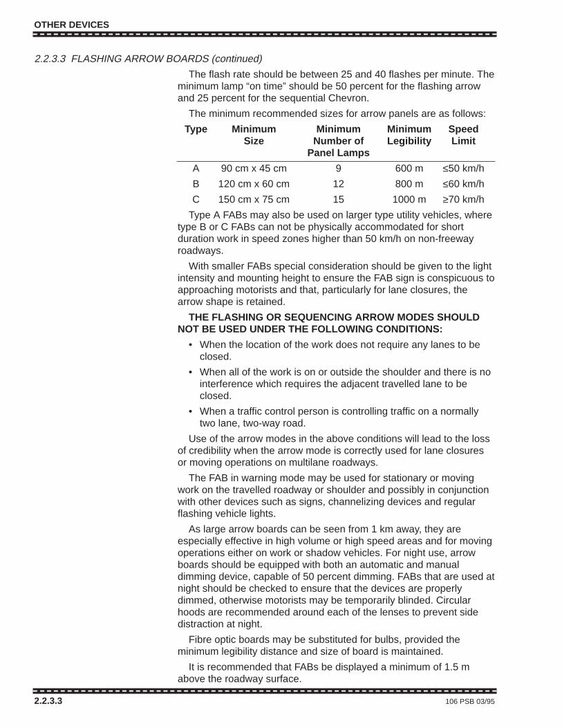
OTHER DEVICES
2.2.3.3 FLASHING ARROW BOARDS (continued)
The flash rate should be between 25 and 40 flashes per minute. Theminimum lamp “on time” should be 50 percent for the flashing arrowand 25 percent for the sequential Chevron.
The minimum recommended sizes for arrow panels are as follows:
Type Minimum Minimum Minimum SpeedSize Number of Legibility Limit
Panel Lamps
A 90 cm x 45 cm 9 600 m ≤50 km/h
B 120 cm x 60 cm 12 800 m ≤60 km/h
C 150 cm x 75 cm 15 1000 m ≥70 km/h
Type A FABs may also be used on larger type utility vehicles, wheretype B or C FABs can not be physically accommodated for shortduration work in speed zones higher than 50 km/h on non-freewayroadways.
With smaller FABs special consideration should be given to the lightintensity and mounting height to ensure the FAB sign is conspicuous toapproaching motorists and that, particularly for lane closures, thearrow shape is retained.
THE FLASHING OR SEQUENCING ARROW MODES SHOULDNOT BE USED UNDER THE FOLLOWING CONDITIONS:
• When the location of the work does not require any lanes to beclosed.
• When all of the work is on or outside the shoulder and there is nointerference which requires the adjacent travelled lane to beclosed.
• When a traffic control person is controlling traffic on a normallytwo lane, two-way road.
Use of the arrow modes in the above conditions will lead to the lossof credibility when the arrow mode is correctly used for lane closuresor moving operations on multilane roadways.
The FAB in warning mode may be used for stationary or movingwork on the travelled roadway or shoulder and possibly in conjunctionwith other devices such as signs, channelizing devices and regularflashing vehicle lights.
As large arrow boards can be seen from 1 km away, they areespecially effective in high volume or high speed areas and for movingoperations either on work or shadow vehicles. For night use, arrowboards should be equipped with both an automatic and manualdimming device, capable of 50 percent dimming. FABs that are used atnight should be checked to ensure that the devices are properlydimmed, otherwise motorists may be temporarily blinded. Circularhoods are recommended around each of the lenses to prevent sidedistraction at night.
Fibre optic boards may be substituted for bulbs, provided theminimum legibility distance and size of board is maintained.
It is recommended that FABs be displayed a minimum of 1.5 mabove the roadway surface.
2.2.3.3 106 PSB 03/95

OTHER DEVICES
2.2.3.4 Overhead Flashing Beacons
Temporary overhead flashing yellow beacons may be used in workzones, both day and night, to warn drivers of such potential hazards asactive truck entrances, and haul road intersections. In specialcircumstances, flashing red beacons may be required to emphasize anotherwise unexpected temporary stop requirement.
Flashing beacons may only be installed with the approval of the roadauthority. They have the same meaning as their permanently installedcounterparts and are not to be used for channelization.
2.2.3.5 Floodlights
Floodlights may be used at night to illuminate work areas, TCPstations and other potentially hazardous locations when other roadwaylighting is not considered adequate or does not exist. Floodlightsshould be shielded or positioned to prevent glare. Floodlighting ofsome areas may decrease relative visibility in other areas and it maybe necessary to provide other devices, such as strings of Type Csteady burn yellow lights to define intended vehicular paths.
Area floodlighting should not be considered as adequate illuminationfor signs or other devices which must be reflectorized or provided withindividual light sources during hours of darkness.
Consideration may also be given to the temporary installation ofluminaires at key locations in long duration work zones such astransitions and important intersections.
PSB 03/95 107 2.2.3.4 – 2.2.3.5
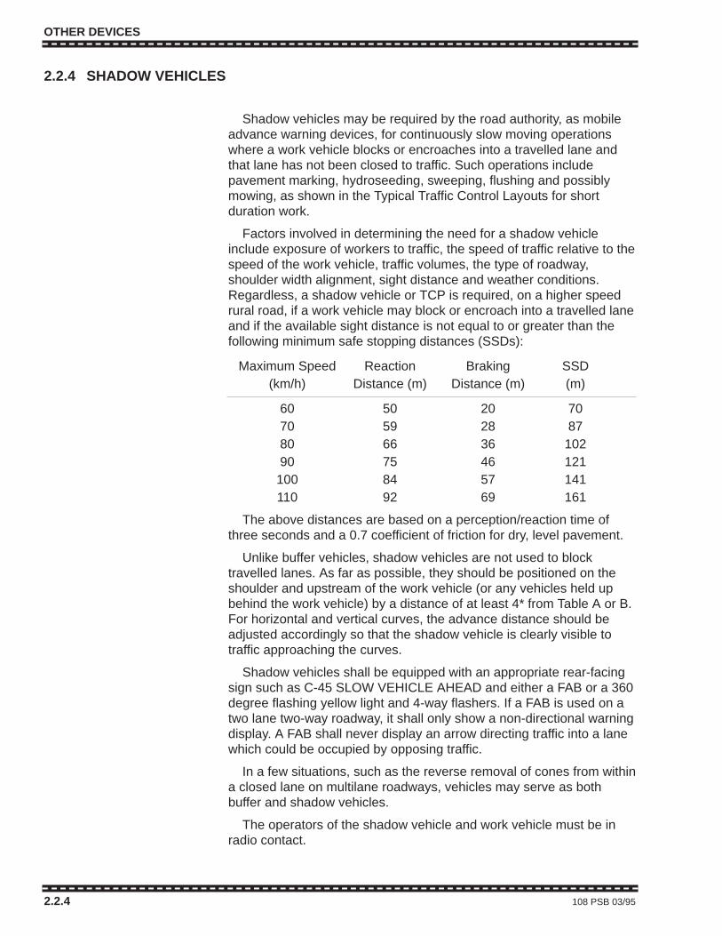
OTHER DEVICES
2.2.4 SHADOW VEHICLES
Shadow vehicles may be required by the road authority, as mobileadvance warning devices, for continuously slow moving operationswhere a work vehicle blocks or encroaches into a travelled lane andthat lane has not been closed to traffic. Such operations includepavement marking, hydroseeding, sweeping, flushing and possiblymowing, as shown in the Typical Traffic Control Layouts for shortduration work.
Factors involved in determining the need for a shadow vehicleinclude exposure of workers to traffic, the speed of traffic relative to thespeed of the work vehicle, traffic volumes, the type of roadway,shoulder width alignment, sight distance and weather conditions.Regardless, a shadow vehicle or TCP is required, on a higher speedrural road, if a work vehicle may block or encroach into a travelled laneand if the available sight distance is not equal to or greater than thefollowing minimum safe stopping distances (SSDs):
Maximum Speed Reaction Braking SSD(km/h) Distance (m) Distance (m) (m)
60 50 20 7070 59 28 8780 66 36 10290 75 46 121100 84 57 141110 92 69 161
The above distances are based on a perception/reaction time ofthree seconds and a 0.7 coefficient of friction for dry, level pavement.
Unlike buffer vehicles, shadow vehicles are not used to blocktravelled lanes. As far as possible, they should be positioned on theshoulder and upstream of the work vehicle (or any vehicles held upbehind the work vehicle) by a distance of at least 4* from Table A or B.For horizontal and vertical curves, the advance distance should beadjusted accordingly so that the shadow vehicle is clearly visible totraffic approaching the curves.
Shadow vehicles shall be equipped with an appropriate rear-facingsign such as C-45 SLOW VEHICLE AHEAD and either a FAB or a 360degree flashing yellow light and 4-way flashers. If a FAB is used on atwo lane two-way roadway, it shall only show a non-directional warningdisplay. A FAB shall never display an arrow directing traffic into a lanewhich could be occupied by opposing traffic.
In a few situations, such as the reverse removal of cones from withina closed lane on multilane roadways, vehicles may serve as bothbuffer and shadow vehicles.
The operators of the shadow vehicle and work vehicle must be inradio contact.
2.2.4 108 PSB 03/95
OTHER DEVICES
2.2.4 SHADOW VEHICLES
Shadow vehicles may be required by the road authority, as mobileadvance warning devices, for continuously slow moving operationswhere a work vehicle blocks or encroaches into a travelled lane andthat lane has not been closed to traffic. Such operations includepavement marking, hydroseeding, sweeping, flushing and possiblymowing, as shown in the Typical Traffic Control Layouts for shortduration work.
Factors involved in determining the need for a shadow vehicleinclude exposure of workers to traffic, the speed of traffic relative to thespeed of the work vehicle, traffic volumes, the type of roadway,shoulder width alignment, sight distance and weather conditions.Regardless, a shadow vehicle or TCP is required, on a higher speedrural road, if a work vehicle may block or encroach into a travelled laneand if the available sight distance is not equal to or greater than thefollowing minimum safe stopping distances (SSDs):
Maximum Speed Reaction Braking SSD(km/h) Distance (m) Distance (m) (m)
60 50 20 7070 59 28 8780 66 36 10290 75 46 121
100 84 57 141110 92 69 161
The above distances are based on a perception/reaction time ofthree seconds and a 0.7 coefficient of friction for dry, level pavement.
Unlike buffer vehicles, shadow vehicles are not used to blocktravelled lanes. As far as possible, they should be positioned on theshoulder and upstream of the work vehicle (or any vehicles held upbehind the work vehicle) by a distance of at least 4* from Table A or B.For horizontal and vertical curves, the advance distance should beadjusted accordingly so that the shadow vehicle is clearly visible totraffic approaching the curves.
Shadow vehicles shall be equipped with an appropriate rear-facingsign such as C-45 SLOW VEHICLE AHEAD and either a FAB or a 360degree flashing yellow light and 4-way flashers. If a FAB is used on atwo lane two-way roadway, it shall only show a non-directional warningdisplay. A FAB shall never display an arrow directing traffic into a lanewhich could be occupied by opposing traffic.
In a few situations, such as the reverse removal of cones from withina closed lane on multilane roadways, vehicles may serve as bothbuffer and shadow vehicles.
The operators of the shadow vehicle and work vehicle must be inradio contact.
2.2.4 108 PSB 03/95
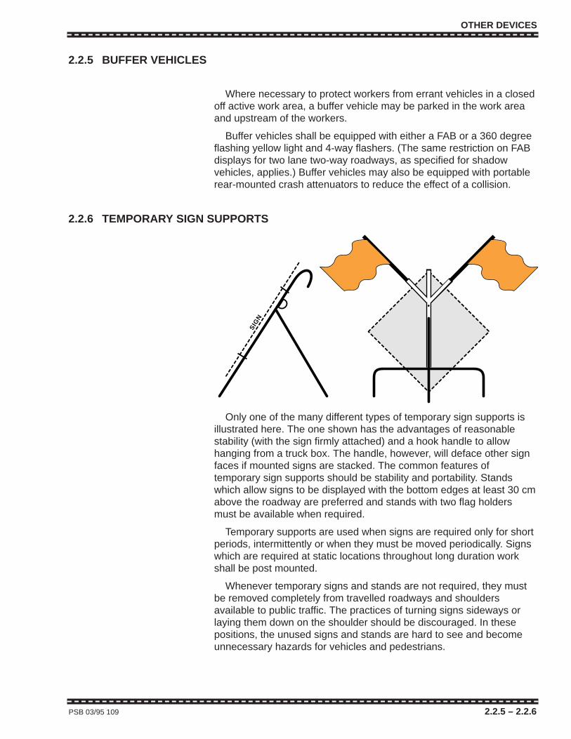
OTHER DEVICES
2.2.5 BUFFER VEHICLES
Where necessary to protect workers from errant vehicles in a closedoff active work area, a buffer vehicle may be parked in the work areaand upstream of the workers.
Buffer vehicles shall be equipped with either a FAB or a 360 degreeflashing yellow light and 4-way flashers. (The same restriction on FABdisplays for two lane two-way roadways, as specified for shadowvehicles, applies.) Buffer vehicles may also be equipped with portablerear-mounted crash attenuators to reduce the effect of a collision.
2.2.6 TEMPORARY SIGN SUPPORTS
Only one of the many different types of temporary sign supports isillustrated here. The one shown has the advantages of reasonablestability (with the sign firmly attached) and a hook handle to allowhanging from a truck box. The handle, however, will deface other signfaces if mounted signs are stacked. The common features oftemporary sign supports should be stability and portability. Standswhich allow signs to be displayed with the bottom edges at least 30 cmabove the roadway are preferred and stands with two flag holdersmust be available when required.
Temporary supports are used when signs are required only for shortperiods, intermittently or when they must be moved periodically. Signswhich are required at static locations throughout long duration workshall be post mounted.
Whenever temporary signs and stands are not required, they mustbe removed completely from travelled roadways and shouldersavailable to public traffic. The practices of turning signs sideways orlaying them down on the shoulder should be discouraged. In thesepositions, the unused signs and stands are hard to see and becomeunnecessary hazards for vehicles and pedestrians.
PSB 03/95 109 2.2.5 – 2.2.6
SIG
N
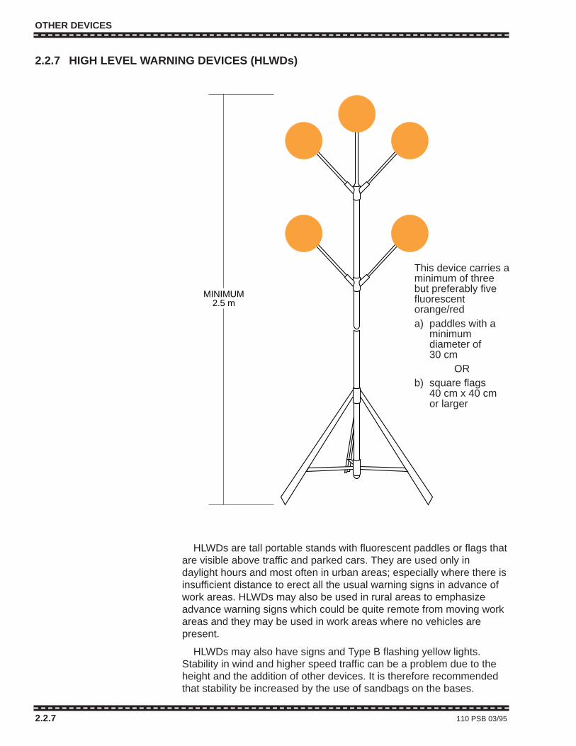
OTHER DEVICES
2.2.7 HIGH LEVEL WARNING DEVICES (HLWDs)
HLWDs are tall portable stands with fluorescent paddles or flags thatare visible above traffic and parked cars. They are used only indaylight hours and most often in urban areas; especially where there isinsufficient distance to erect all the usual warning signs in advance ofwork areas. HLWDs may also be used in rural areas to emphasizeadvance warning signs which could be quite remote from moving workareas and they may be used in work areas where no vehicles arepresent.
HLWDs may also have signs and Type B flashing yellow lights.Stability in wind and higher speed traffic can be a problem due to theheight and the addition of other devices. It is therefore recommendedthat stability be increased by the use of sandbags on the bases.
2.2.7 110 PSB 03/95
MINIMUM2.5 m
This device carries aminimum of threebut preferably fivefluorescentorange/reda) paddles with a
minimumdiameter of30 cm
ORb) square flags
40 cm x 40 cmor larger

OTHER DEVICES
2.2.8 TEMPORARY LANE CONTROL SIGNALS
2.2.8.1 GeneralTemporary lane control signal systems may be used in place of
TCPs, in short duration work zones, to control sections of alternatingone-way traffic on normally two-way roadways. Systems are generallyradio controlled, battery-operated and consist of a “master”(transmitter) unit at one end and a “slave” (receiver only) unit at theother. Each unit should display at least one three colour signal headwith backboard, as illustrated.
Temporary lane control signal systems must be equipped with aconflict monitor and shall have a manual override at the master unit.Due to problems which could occur through battery failure or lampburnout in single heads, these devices should be attended at all times.It is emphasized that, except in emergency situations, use of theseunits on Ministry roadways is only authorized for short duration(daytime) operations.
Temporary lane control signals (and temporary traffic signals usedfor alternating one-way control) should be timed as shown in 2.2.8.2following.
PSB 03/95 111 2.2.8 – 2.2.8.1
100 cm
50 cm
traffic signal headcomplete with20 cm lensesand backboard(yellow preferred)
2.5 m
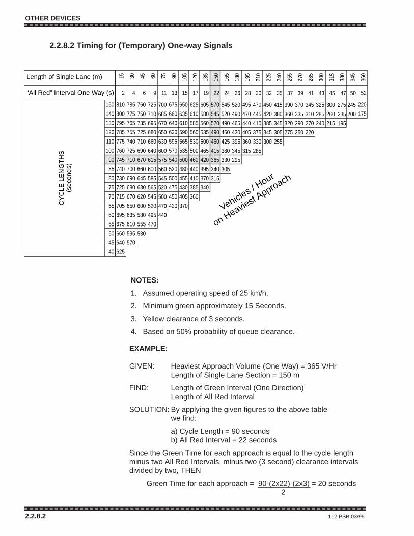
OTHER DEVICES
2.2.8.2 Timing for (Temporary) One-way Signals
2.2.8.2 112 PSB 03/95
52
220
175
Length of Single Lane (m)
“All Red” Interval One Way (s) 2
810
800
795
785
775
760
745
740
730
725
715
705
695
675
660
640
625
4
785
775
765
755
740
725
710
700
690
680
670
650
635
610
595
570
6
760
750
735
725
710
690
670
660
645
630
620
600
580
555
530
9
725
710
695
680
660
640
615
600
585
565
545
520
495
470
11
700
685
670
650
630
600
575
560
545
520
500
470
440
13
675
660
640
620
595
570
540
520
500
475
450
420
15
650
635
610
590
565
535
500
480
455
430
405
370
17
625
610
585
560
530
500
460
440
410
385
360
19
605
580
560
535
500
465
420
395
370
340
22
570
545
520
490
460
415
365
340
315
24
545
520
490
460
425
380
330
305
26
520
490
465
430
395
345
295
28
495
470
440
405
360
315
30
470
445
410
375
330
285
32
450
420
385
345
300
35
415
380
345
305
255
37
390
360
320
275
39
370
335
290
250
41
345
310
270
220
43
325
285
240
45
300
260
215
47
275
235
195
50
245
200
150
140
130
120
110
100
90
85
80
75
70
65
60
55
50
45
40
15 30 45 60 75 90 105
120
135
150
165
180
195
210
225
240
255
270
285
300
315
330
345
360
CY
CLE
LE
NG
TH
S(s
econ
ds)
Vehicles / Hour
on Heaviest Approach
NOTES:
1. Assumed operating speed of 25 km/h.
2. Minimum green approximately 15 Seconds.
3. Yellow clearance of 3 seconds.
4. Based on 50% probability of queue clearance.
EXAMPLE:
GIVEN: Heaviest Approach Volume (One Way) = 365 V/HrLength of Single Lane Section = 150 m
FIND: Length of Green Interval (One Direction)Length of All Red Interval
SOLUTION: By applying the given figures to the above tablewe find:
a) Cycle Length = 90 secondsb) All Red Interval = 22 seconds
Since the Green Time for each approach is equal to the cycle length minus two All Red Intervals, minus two (3 second) clearance intervalsdivided by two, THEN
Green Time for each approach = 90-(2x22)-(2x3) = 20 seconds2

OTHER DEVICES
2.2.9 FLAGS ON HLWDs AND TEMPORARY SIGN SUPPORTSFluorescent red or orange flags may be used on HLWDs, as
indicated in Section 2.2.7 and with signs temporarily mounted asshown in Section 2.2.6. They are square and a minimum size of 40 cmx 40 cm. Three or, preferably, five flags may be displayed on HLWDsand two flags on other temporary sign supports.
Flags may be used with any signs mounted on temporary supports.They are required, however, in speed zones of 70 km/h or higher fortemporary signs which give warning of people working on or adjacentto a roadway. These signs include C-4 CREW WORKING AHEAD,C-28 TRAFFIC CONTROL PERSON AHEAD, C-36 SURVEY CREWAHEAD and C-58 ACCIDENT SCENE AHEAD.
Flags should be made of non-rigid material which will allow them to“flutter” in wind or in air disturbed by passing vehicles.
When mounted, flags should be positioned so that, moving or still,they do not interfere with sign messages.
Flags shall not be used by TCPs to direct the movement of traffic.
PSB 03/95 113 2.2.9

OTHER DEVICES
2.3.3 – 2.3.5 114 PSB 03/95
OTHER DEVICES
2.3.3 – 2.3.5 114 PSB 03/95
TRAFFIC CONTROL PERSONS (TCPs)
2.3 TRAFFIC CONTROL PERSONS (TCPs)2.3.1 GENERAL
TCPs are used to regulate traffic to prevent conflicts between themovement of pedestrians, vehicles, workers and work zoneequipment. They may also be used to slow traffic passing close toworkers or equipment. TCPs are employed when all other methods ofcontrolling traffic are considered inadequate to warn, direct, andregulate drivers.
Common applications for TCPs are control of alternating one-waytraffic through sections of two-way road temporarily reduced to onelane, and for stopping public traffic to permit work zone equipment toenter or cross a road, etc.
One or both TCPs at a site may be omitted and self regulation oftraffic allowed, under the conditions described in the notes for Figure3.4.1, provided that the self regulated section does not extend throughan intersection. A temporary lane control signal or temporary trafficsignal may also be used in place of TCPs to control traffic on sectionsof one lane two-way roadway. See Section 2.2.8.
TCPs are not generally required as part of the traffic control for areduction in the number of lanes on multilane roads.
2.3.2 RESPONSIBILITYIt is the responsibility of the traffic control person to effectively
communicate with the travelling public by using traffic control motionsand signals that are precise and deliberate so that the meaning ofsignals can be clearly understood.
2.3.3 QUALIFICATIONSTCPs have a high level of contact with the public and should
therefore be carefully selected and thoroughly trained. Training shouldconsist of the successful completion of a recognized course. TCPsshould possess the following characteristics:
• Intelligence and common sense.
• Alertness.
• A courteous but firm manner.
• A sense of responsibility for the safety of workers and the public.
• Good physical condition, especially sight and hearing.
• Neat appearance.
• Current certification of training to an approved standard.
1926 01/99 115 2.3 – 2.3.3

2.3.4 TRAININGThe W.C.B. Occupational Health and Safety Regulations require that
TCPs be given written instructions on the performance of their duties.The instructions should include but not be limited to the Regulationsand Section 2.3 of this Manual. A TCP desirably should have workingknowledge of this Manual.
The following points should be emphasized in the training of TCPs:
• Importance of their job.
• Need for a courteous but firm manner.
• Personal protective equipment which conforms to OccupationalHealth and Safety Regulations (Part 8) for high visibility appareland safety headgear
• Signals made by TCPs to control traffic must conform to theW.C.B. Occupational Health and Safety Regulations.
• Proper positioning in relation to the work area in order to beeffective and ensure the safety of the public, workers, equipmentand the TCP.
• Alertness.
• Discipline to prevent others from loitering near the TCP positionand not to leave the position until relieved or the conflict beingcontrolled no longer exists.
• Requirement to remove C-28 Traffic Control Person Ahead signswhenever TCPs are not in position.
2.3.5 EQUIPMENTA C-28 TCP Ahead sign must be in place in advance of any TCP.
The C-27 Traffic Control (stop and slow) Paddle, used by TCPs, musthave retroreflectorized sheeting. No substitutes will be permitted.TCPs must be provided with equipment if necessary for effectivecommunication between partner TCPs when TCPs are not visible toeach other (see also 2.3.6 Positioning). C-27 paddles may becomfortably displayed by use of a 1.3 m handle extension described insec 2.1.5, C-27. When it is only necessary to slow traffic in onedirection the STOP side of the control paddle should be hidden by theTCPs body.
If TCPs are required after dark their positions should, if possible, beilluminated. TCPs should also be supplied with flashlights equippedwith red signalling batons and spare batteries
Each TCP must use personal protective equipment consisting ofhigh visibility apparel and safety headgear meeting OccupationalHealth and Safety Regulations (Part 8). Their personal protectiveequipment must be kept clean and in working condition.
2.3.6 POSITIONINGIf a TCP can not be positioned so there will be no interference with
other traffic control devices such as stop signs or a traffic signal it maybe necessary to place covers over stop signs or to flash signals inorder to avoid contradictory instructions to drivers.
TRAFFIC CONTROL PERSONS (TCPs)
2.3.4 – 2.3.6 116 1926 01/99
TRAFFIC CONTROL PERSONS (TCPs)
TCPs should be positioned in accordance with the following:
• Stand outside the lane carrying moving traffic.
• Unless otherwise specified stand 25 - 75 m from the work area inorder to provide some manoeuvering room for lane changing orfor an out of control vehicle.
• Always face moving traffic but be aware of what is happening inthe stopped lane.
• Where work is in progress adjacent to an intersection, it may benecessary to stand in the middle of the intersection in which caseit may not be possible to conform to one or more of the threepoints above.
• Stand where the TCP can see and be seen by approachingdrivers. To the extent practical, stand where the background willmake the TCP as conspicuous as possible.
• Notwithstanding the above points, the TCP should stand at themost appropriate location to direct traffic through a work area,consistent with the Industrial Health and Safety Regulations.
• Plan an escape route.
• If there is no line of sight between two TCPs, and they do nothave radio communication, it will be necessary to position a thirdTCP between the two to relay visual signals.
1926 01/99 117 2.3.6
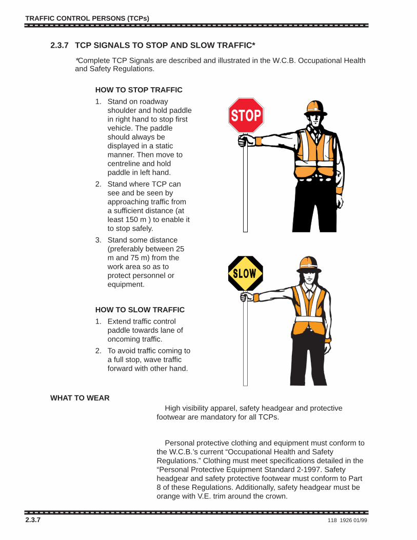
TRAFFIC CONTROL PERSONS (TCPs)
2.3.7 118 1926 01/99
2.3.7 TCP SIGNALS TO STOP AND SLOW TRAFFIC*
*Complete TCP Signals are described and illustrated in the W.C.B. Occupational Healthand Safety Regulations.
HOW TO STOP TRAFFIC
1. Stand on roadwayshoulder and hold paddlein right hand to stop firstvehicle. The paddleshould always bedisplayed in a staticmanner. Then move tocentreline and holdpaddle in left hand.
2. Stand where TCP cansee and be seen byapproaching traffic froma sufficient distance (atleast 150 m ) to enable itto stop safely.
3. Stand some distance(preferably between 25m and 75 m) from thework area so as toprotect personnel orequipment.
HOW TO SLOW TRAFFIC
1. Extend traffic controlpaddle towards lane ofoncoming traffic.
2. To avoid traffic coming toa full stop, wave trafficforward with other hand.
WHAT TO WEARHigh visibility apparel, safety headgear and protective
footwear are mandatory for all TCPs.
Personal protective clothing and equipment must conform tothe W.C.B.’s current “Occupational Health and SafetyRegulations.” Clothing must meet specifications detailed in the“Personal Protective Equipment Standard 2-1997. Safetyheadgear and safety protective footwear must conform to Part8 of these Regulations. Additionally, safety headgear must beorange with V.E. trim around the crown.

TRAFFIC CONTROL PERSONS (TCPs)
2.3.8 LOCATION OF TRAFFIC CONTROL PERSONS
1926 01/99 118.1 2.3.8
TCP
TCP
WORK AREA
TCP 1
TCP 2
WORK AREA
TCP 3
25 - 35 mWORK AREA
TCP 3
50 - 75TCP 2
TCP 1
TCP 1 TCP 2
TCP 3WORK AREA
25 - 35 m
50 - 75 m
50 - 75 m
25 - 35 mSTRAIGHTROAD
CURVE
HILL
NOTE:On curves or hills, TCP locations 1 and 2 may not be intervisible. If radio communication is notavailable in such cases, a third TCP will be required as shown to relay signals between TCPs 1 and 2.

TRAFFIC CONTROL PERSONS (TCPs)
118.2 1926 01/99
TRAFFIC CONTROL PERSONS (TCPs)
118.2 1926 01/99

CHAPTER 3 – SHORT DURATION
1926 01/99 119 Legend
TUBULAR MARKER – TYPE D
CONE – TYPE A, B or C
SIGN
TRAFFIC CONTROL PERSON (TCP)
SHADOW, BUFFER or WORK VEHICLE
(360°) FLASHING YELLOW LIGHT
WORK AREA
PORTABLE LANE CONTROL SIGNAL
BARRICADES and FENCING
FLASHING ARROW BOARD (FAB)
HIGH LEVEL WARNING DEVICE (HLWD)
LEGEND
CHAPTER 3TYPICAL TRAFFIC CONTROL LAYOUTSFOR SHORT DURATION WORK ZONES
Exception for Emergency and Brief Duration WorkIf the work being carried out is of an emergency or brief duration nature, as defined, andis within a speed limit of 60 km/h or less, it may not be practicable to provide the TCPsor advance signing called for in Chapters 3 and 4 of the Traffic Control Manual.

CHAPTER 3 – SHORT DURATION
Table A 120 PSB 03/95
*Regulatory 50 60 70 80 90-100speed limit km/h km/h km/h km/h km/h
1aTaper length 35 55 75 90 110for lane closure (1:10) (1:15) (1:20) (1:25) (1:30)
Taper length
1bfor shoulder work
5 8 10 12 15or where TCPs used(min. 3 cones)
Maximum distance2 between cones 10 10 10 10 10
or tubular markersfor 1a
3Minimum tangent
30 60 90 120 150distance betweentapers
4Distance between
40 60 80 100 150construction signs
TABLE APositioning of devices on conventional roadways for various speed limits.
Dimensions shown are in metres and are minimums except for 2*.
Cones and tubular markers are generally used in daylight but if used at night must bereflectorized. Barricades, flexible drums or temporary delineator posts are generallyused during hours of darkness and must be reflectorized.
Dimensions 1b* apply to downstream tapers, shoulder tapers, and to two-way traffictapers on travelled lanes where traffic is controlled by TCPs, portable lane controlsignals or temporary traffic signals.
Dimensions 4* represent the minimum advance placement distances for initial signs aswell as distances between subsequent signs in multi-sign series.

CHAPTER 3 – SHORT DURATION
PSB 03/95 121 3.1.1 – 3.1.2
OR
OR
SE
E TA
BLE
A
360°
MAR. 95
Figure 3.1.1 Work on Shoulder (Less Than 30 Minutes)
1b*
AND4-WAY FLASHERS
(A)Work Vehicles Present
(B)Work Vehicles Not Present
OR
OR
SE
E TA
BLE
A
360°
MAR. 95
Figure 3.1.2 Work on Shoulder (30 Minutes or Greater)
1b*4*1b*
AND4-WAY FLASHERS
C-4
(A)Work Vehicles Present
(B)Work Vehicles Not Present

CHAPTER 3 – SHORT DURATION
3.2.1 122 1926 01/99
C-38
OR
4*50-75m
4*
C-28
TW-59
C-38
C-39&
C-40D
Figure 3.2.1 Intermittent Moving Work – Two Lane Two-way Roadway
1926-3.2.1 (99/01)
360°
PLUS
AND 4-WAYFLASHERS
25-35 m
SE
E TA
BLE
A
C-28
C-27
C-27
4* min.
4* min. 1b*
• Typical applications are Benkleman beam testing, reflective road stud installation,temporary patching, crack sealing, etc.
• Distance on C-38 signs should not exceed 2 km.
• A Type B flashing yellow light or flags shall be used with C-38 signs. Addition of aHLWD is optional.
• If speed limit is 60 km/h or less the C-38 sign and its accessories may be omitted.
• A shadow vehicle with a C-45 or other appropriate sign on the rear may be requiredby the road authority.
• C-39 and TW-59 signs should be removed or covered and the C-40D sign loweredwhen work vehicles travel at posted speeds.
• C-40D may be omitted from large line-type utility vehicles if it is impractical to mountthe sign.

CHAPTER 3 – SHORT DURATION
PSB 03/95 123 3.2.2
OR360°
Figure 3.2.2 Continuously Slow Moving Work – Two Lane Two-way Roadway
MAR. 95
PLUS4-WAYFLASHERS
SE
E TA
BLE
A
C-44
C-44
R-56
TW-59
4* min.
• For pavement striping see Appendix B of the Traffic Control Manual.
• Typical applications are hydroseeding, grading, sweeping and flushing, etc.
• Maximum distance on C-44 signs should not exceed 8 km.
• A Type B flashing yellow light or flags shall be used with C-44 signs. Addition of aHLWD is optional.
• If speed limit is 60 km or less, the C-44 sign and its accessories may be omitted.
• All signs should be removed or covered when work is not underway and work vehiclescan travel at posted speeds.
• A shadow vehicle with a C-45 or other appropriate sign on the rear may be requiredby the road authority.
• R-56 may be omitted from large line-type utility vehicles if it is impractical to mount thesign.

CHAPTER 3 – SHORT DURATION
3.2.3 124 PSB 03/95
Figure 3.2.3 Continuously Slow Moving Work – Multilane Roadway
C-44TW-59
MAR. 95
SE
E TA
BLE
A
4* min.
• For pavement striping, see Appendix B of the Traffic Control Manual.
• Typical applications are hydroseeding, grading, flushing and sweeping etc.
• Maximum distance on C-44 sign should not exceed 8 km.
• A Type B flashing yellow light or flags shall be used with the C-44 sign. Addition of aHLWD is optional.
• If speed limit is 60 km or less, the C-44 sign and its accessories may be omitted .
• If speed limit is 60 km/h or less, the FAB can be replaced by a 360° plus 4-wayflashers.
• All signs should be covered or removed when work vehicles can proceed at postedspeeds.
• A shadow vehicle with a C-45 or other appropriate sign on the rear may be requiredby the road authority.
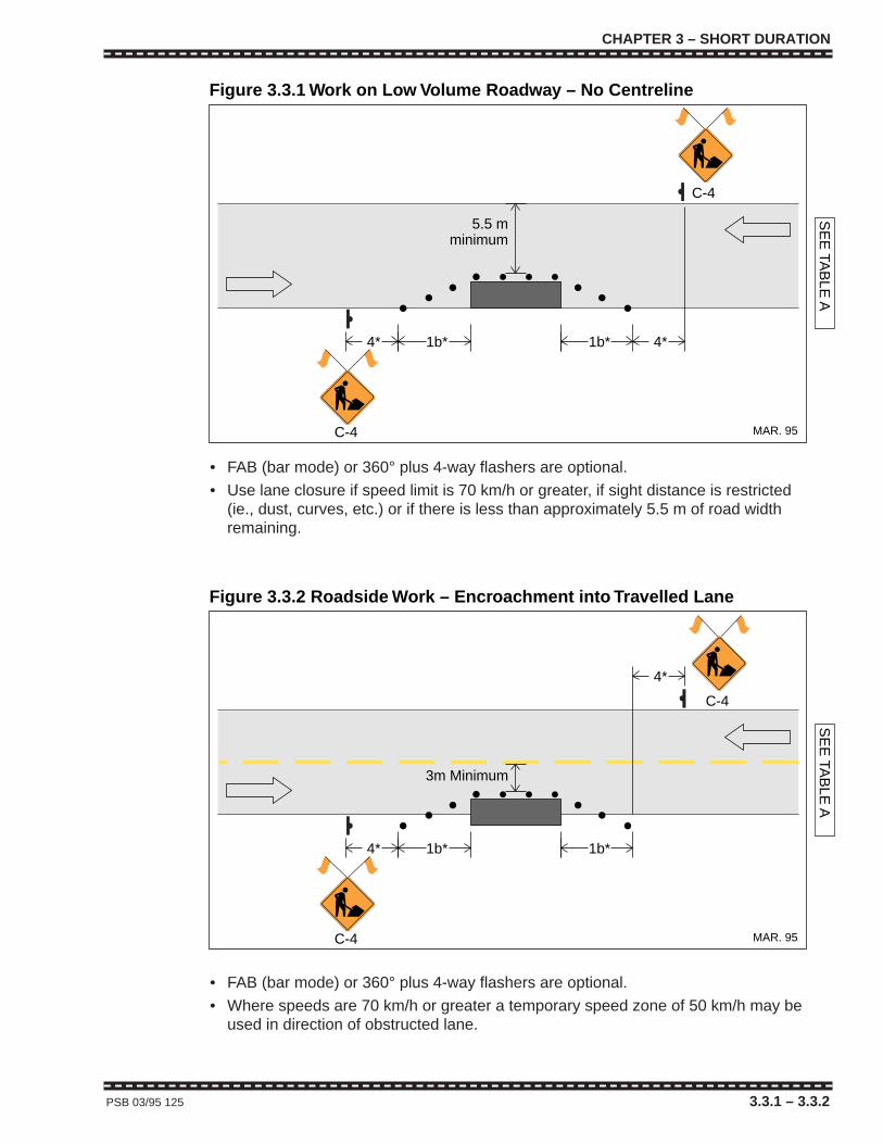
CHAPTER 3 – SHORT DURATION
PSB 03/95 125 3.3.1 – 3.3.2
C-4
C-4
4* 1b* 4*
SE
E TA
BLE
A
Figure 3.3.1 Work on Low Volume Roadway – No Centreline
MAR. 95
1b*
5.5 mminimum
• FAB (bar mode) or 360° plus 4-way flashers are optional.
• Use lane closure if speed limit is 70 km/h or greater, if sight distance is restricted(ie., dust, curves, etc.) or if there is less than approximately 5.5 m of road widthremaining.
C-4
C-4
4* 1b*
4*
3m Minimum
SE
E TA
BLE
A
Figure 3.3.2 Roadside Work – Encroachment into Travelled Lane
MAR. 95
1b*
• FAB (bar mode) or 360° plus 4-way flashers are optional.
• Where speeds are 70 km/h or greater a temporary speed zone of 50 km/h may beused in direction of obstructed lane.

CHAPTER 3 – SHORT DURATION
3.3.3 – 3.4.1 126 1926 01/99
C-4
25-35m
C-24 C-28
1b*
50-75m
4*4*
4* 4*4*
4*
C-27
C-27
SE
E TA
BLE
A
C-24C-28
Figure 3.4.1 Lane Closure with TCPs – Two Lane Two-way Roadway
1926-3.4.1 (99/01)C-4
1b*
• For a temporary speed zone, place C-1 signs at positions shown for C-24s. Moveboth C-24 and C-4 signs a further 4* upstream. Place C-23 signs downstream ofeach TCP.
• If the one lane section is sufficiently short (e.g., a spot obstruction), sight distance isadequate, and traffic volumes are light, it may be possible to omit the TCP for theopen lane or possibly even both TCPs, and let traffic flow be self regulating. If theTCP for the open lane is omitted, the corresponding C-28 sign must be omitted. If theTCP for the closed lane is also omitted, the C-28 for that direction must be replacedwith an R-56 Yield to Oncoming Traffic. If both TCPs are omitted, a Class 1 barricademust be added on each side of the work zone.
SE
E TA
BLE
A
Figure 3.3.3 Work in Parking Lane – Urban Area
MAR. 95
1b*
• FAB (bar mode) or 360° plus4-way flashers are optional.

CHAPTER 3 – SHORT DURATION
PSB 03/95 127 3.4.2 – 3.4.3
C-4 TW-61T
4*4*4*
1a*
2*
TW-61R
SE
E TA
BLE
A
Figure 3.4.3 Right Lane Closed – Multilane Roadway
MAR. 95
C-24 TW-12C-24
SE
E TA
BLE
A
4* 4* 4*
15m1b*4*4*4*
15m
15m
1b*
15m
R-35R TW-12R-35R
C-4
C-4
Figure 3.4.2 Lane Closure With Temporary Lane Control SignalsFigure 3.4.2 – Two Lane Two-way Roadway
MAR. 95
• See Section 2.2.8.2 for timingof temporary lane controlsignals.
• If the speed limit is 60 km/h or less the upstream TW-61R may be omitted and theC-4 moved downstream by 4*.
• Substitution for the Fab sign may be made as indicated in the following table:
Speed Limit Workers or Work No Workers orVehicle Present Vehicles Present
≤60 C-53 plus 360° & C-53 plus4 way flashers or HLWDC-53 plus HLWD
≥ 70 No Substitution C-53 plusHLWD

CHAPTER 3 – SHORT DURATION
3.4.4 – 3.4.5 128 PSB 03/95
1a*4*4*
SE
E TA
BLE
A
C-53
C-30
3* 1a*
C-4 TW-61RTW-61T
TW-61R
2*
2*
4*
Figure 3.4.5 Centre Lane Closed – Multilane Roadway
MAR. 95
60 m 60 m 60 m 60 m
• See footnotes for Figure 3.4.3
TW-61L
C-4
4*4*4*
1a*
2*
TW-61T
SE
E TA
BLE
A
Figure 3.4.4 Left Lane Closed – Multilane Roadway
MAR. 95• See footnotes for Figure 3.4.3
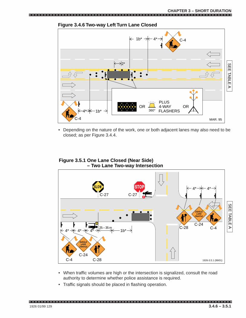
CHAPTER 3 – SHORT DURATION
1926 01/99 129 3.4.6 – 3.5.1
C-4C-24
1b*
C-28
25 – 35 m
C-27 C-27
4*4*
SE
E TA
BLE
AC-24
4* 4* 4*C-4C-28
Figure 3.5.1 One Lane Closed (Near Side)Figure 3.5.1 – Two Lane Two-way Intersection
1926-3.5.1 (99/01)
PLUS4-WAYFLASHERS
OR OR
2* SE
E TA
BLE
A
360°
4*1b*
1b*4*
C-4
C-4
Figure 3.4.6 Two-way Left Turn Lane Closed
MAR. 95
• Depending on the nature of the work, one or both adjacent lanes may also need to beclosed; as per Figure 3.4.4.
• When traffic volumes are high or the intersection is signalized, consult the roadauthority to determine whether police assistance is required.
• Traffic signals should be placed in flashing operation.
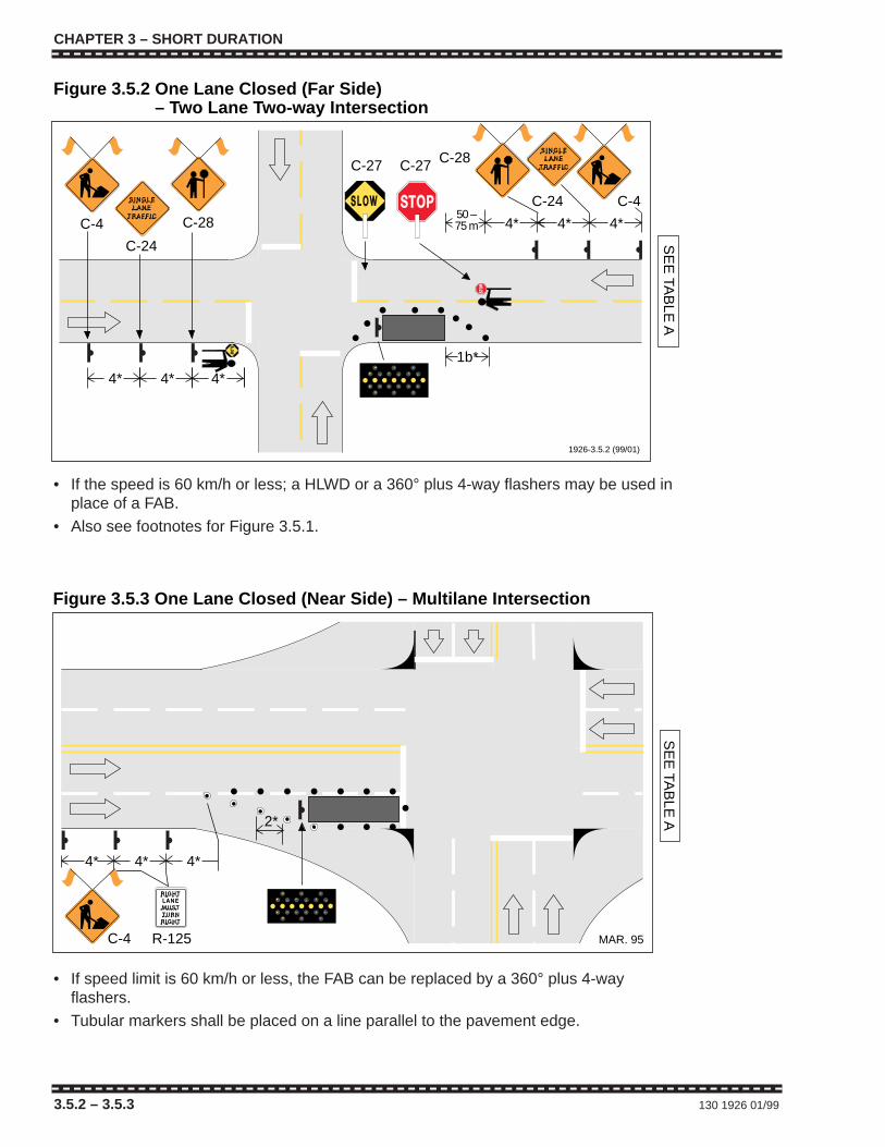
CHAPTER 3 – SHORT DURATION
3.5.2 – 3.5.3 130 1926 01/99
C-4
4*4*4*
2*
SE
E TA
BLE
A
Figure 3.5.3 One Lane Closed (Near Side) – Multilane Intersection
R-125 MAR. 95
C-4
C-28
C-2450 –75 m 4*C-4
C-24
C-28
C-27
4*4* 4*
4* 4*
SE
E TA
BLE
A
C-27
Figure 3.5.2 One Lane Closed (Far Side)Figure 3.5.2 – Two Lane Two-way Intersection
1926-3.5.2 (99/01)
1b*
• If the speed is 60 km/h or less; a HLWD or a 360° plus 4-way flashers may be used inplace of a FAB.
• Also see footnotes for Figure 3.5.1.
• If speed limit is 60 km/h or less, the FAB can be replaced by a 360° plus 4-wayflashers.
• Tubular markers shall be placed on a line parallel to the pavement edge.
CHAPTER 3 – SHORT DURATION
3.5.2 – 3.5.3 130 1926 01/99
C-4
4*4*4*
2*
SE
E TA
BLE
A
Figure 3.5.3 One Lane Closed (Near Side) – Multilane Intersection
R-125 MAR. 95
C-4
C-28
C-2450 –75 m 4*C-4
C-24
C-28
C-27
4*4* 4*
4* 4*S
EE
TAB
LE A
C-27
Figure 3.5.2 One Lane Closed (Far Side)Figure 3.5.2 – Two Lane Two-way Intersection
1926-3.5.2 (99/01)
1b*
• If the speed is 60 km/h or less; a HLWD or a 360° plus 4-way flashers may be used inplace of a FAB.
• Also see footnotes for Figure 3.5.1.
• If speed limit is 60 km/h or less, the FAB can be replaced by a 360° plus 4-wayflashers.
• Tubular markers shall be placed on a line parallel to the pavement edge.

CHAPTER 3 – SHORT DURATION
PSB 03/95 131 3.5.4 – 3.6.1
C-4 TW-61T
4*4* 1a
TW-61L
1a*
Variable to suit left turn demands.
4*
SE
E TA
BLE
A
2*
C-53
Figure 3.5.4 One Lane Closed (Far Side) – Multilane Intersection
MAR. 95
C-4
1a*
2*
4*
TW-61T
TW-
SE
E TA
BLE
A
4*4*
Figure 3.6.1 Sidewalk Detour onto Roadway
R-125
MAR. 95
• See footnotes for Figure 3.4.3
• See footnotes for Figure 3.4.3

3.7 PAVEMENT MARKING
GENERAL
Two Lane Two-way Rural RoadwaySee Part C, Appendix B.
Multilane Rural RoadwaySee Part C, Appendix B.
IntersectionsFigures 3.7.1 to 3.7.3 inclusive indicate traffic control required forinstallation of pavement arrows, stopline and crosswalk markings.
4*
C-4
SE
E TA
BLE
A
Figure 3.7.1 Marking – Left Turn Arrows
MAR. 95
CHAPTER 3 – SHORT DURATION
3.7 – 3.7.1 132 PSB 03/95
• The C-4 sign may be removed when the painting operation is complete and noworkers are present. The Type A cones remain until the paint has dried.
• A vehicle with a FAB or a 360° plus 4-way flashers shall be stationed within theupstream island when the speed limit is 70 km/h or higher and workers are present.
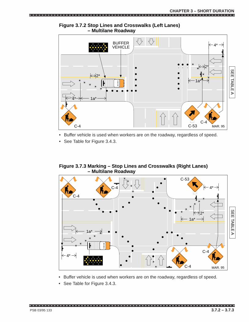
CHAPTER 3 – SHORT DURATION
PSB 03/95 133 3.7.2 – 3.7.3
C-4
2*
4* 1a*
1a*
4*
2* SE
E TA
BLE
A
C-4C-53
Figure 3.7.2 Stop Lines and Crosswalks (Left Lanes)Figure 3.7.2 – Multilane Roadway
MAR. 95
BUFFERVEHICLE
2*
4*
C-53
C-4
C-4
C-4S
EE
TAB
LE A
4*
1a*
1a*
C-4
Figure 3.7.3 Marking – Stop Lines and Crosswalks (Right Lanes)Figure 3.7.3 – Multilane Roadway
MAR. 95
• Buffer vehicle is used when workers are on the roadway, regardless of speed.
• See Table for Figure 3.4.3.
• Buffer vehicle is used when workers are on the roadway, regardless of speed.
• See Table for Figure 3.4.3.
CHAPTER 3 – SHORT DURATION
PSB 03/95 133 3.7.2 – 3.7.3
C-4
2*
4* 1a*
1a*
4*
2* SE
E TA
BLE
A
C-4C-53
Figure 3.7.2 Stop Lines and Crosswalks (Left Lanes)Figure 3.7.2 – Multilane Roadway
MAR. 95
BUFFERVEHICLE
2*
4*
C-53
C-4
C-4
C-4
SE
E TA
BLE
A
4*
1a*
1a*
C-4
Figure 3.7.3 Marking – Stop Lines and Crosswalks (Right Lanes)Figure 3.7.3 – Multilane Roadway
MAR. 95
• Buffer vehicle is used when workers are on the roadway, regardless of speed.
• See Table for Figure 3.4.3.
• Buffer vehicle is used when workers are on the roadway, regardless of speed.
• See Table for Figure 3.4.3.
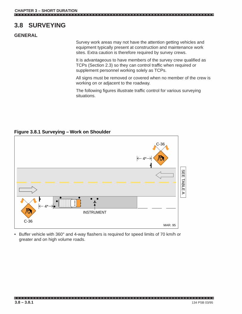
CHAPTER 3 – SHORT DURATION
3.8 – 3.8.1 134 PSB 03/95
• Buffer vehicle with 360° and 4-way flashers is required for speed limits of 70 km/h orgreater and on high volume roads.
3.8 SURVEYING
GENERALSurvey work areas may not have the attention getting vehicles andequipment typically present at construction and maintenance worksites. Extra caution is therefore required by survey crews.
It is advantageous to have members of the survey crew qualified asTCPs (Section 2.3) so they can control traffic when required orsupplement personnel working solely as TCPs.
All signs must be removed or covered when no member of the crew isworking on or adjacent to the roadway.
The following figures illustrate traffic control for various surveyingsituations.
4*
4*
INSTRUMENT
C-36
SE
E TA
BLE
A
C-36
Figure 3.8.1 Surveying – Work on Shoulder
MAR. 95
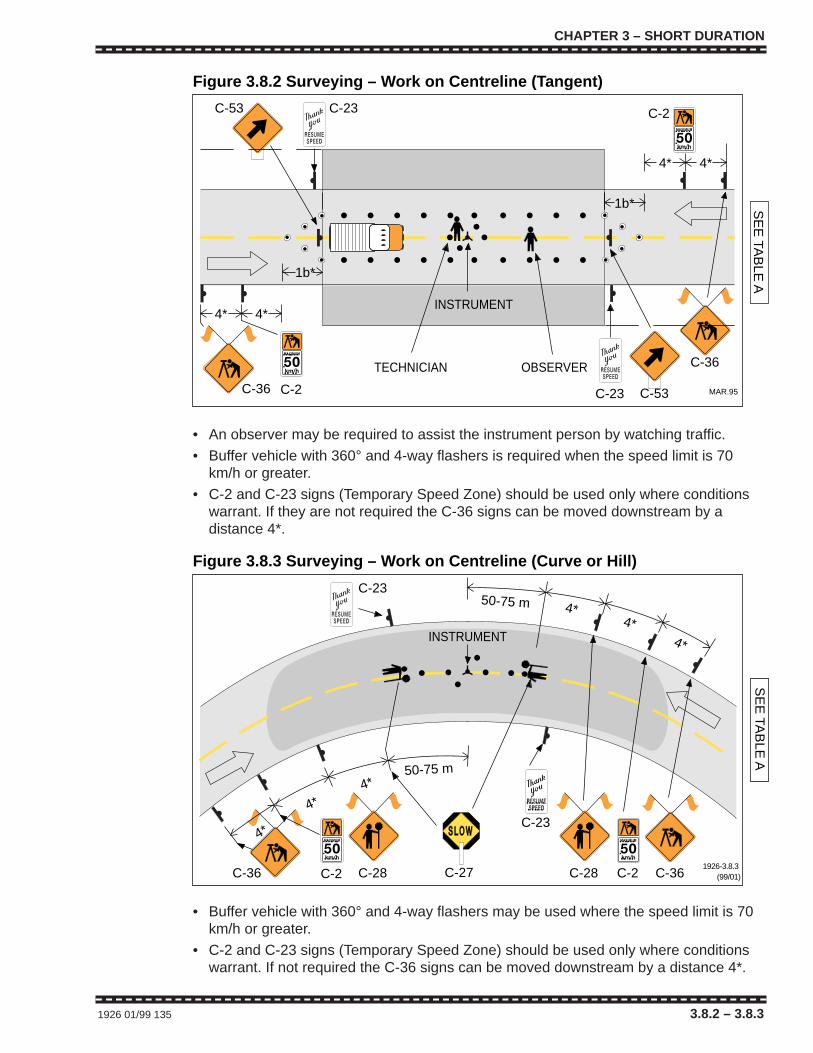
CHAPTER 3 – SHORT DURATION
1926 01/99 135 3.8.2 – 3.8.3
C-36
INSTRUMENT
C-2
4*
C-23
TECHNICIAN
4*
1b*
4*
C-23
SE
E TA
BLE
A
OBSERVER
4*
1b*
C-53
C-53
C-36
C-2
Figure 3.8.2 Surveying – Work on Centreline (Tangent)
MAR.95
• An observer may be required to assist the instrument person by watching traffic.
• Buffer vehicle with 360° and 4-way flashers is required when the speed limit is 70km/h or greater.
• C-2 and C-23 signs (Temporary Speed Zone) should be used only where conditionswarrant. If they are not required the C-36 signs can be moved downstream by adistance 4*.
C-36
INSTRUMENT
C-2
50-75 m4*
4*
4*
50-75 m 4*4*
4*
C-23
C-23
SE
E TA
BLE
AC-36C-2C-28
Figure 3.8.3 Surveying – Work on Centreline (Curve or Hill)
1926-3.8.3 (99/01)C-27 C-28
• Buffer vehicle with 360° and 4-way flashers may be used where the speed limit is 70km/h or greater.
• C-2 and C-23 signs (Temporary Speed Zone) should be used only where conditionswarrant. If not required the C-36 signs can be moved downstream by a distance 4*.
CHAPTER 3 – SHORT DURATION
1926 01/99 135 3.8.2 – 3.8.3
C-36
INSTRUMENT
C-2
4*
C-23
TECHNICIAN
4*
1b*
4*
C-23
SE
E TA
BLE
A
OBSERVER
4*
1b*
C-53
C-53
C-36
C-2
Figure 3.8.2 Surveying – Work on Centreline (Tangent)
MAR.95
• An observer may be required to assist the instrument person by watching traffic.
• Buffer vehicle with 360° and 4-way flashers is required when the speed limit is 70km/h or greater.
• C-2 and C-23 signs (Temporary Speed Zone) should be used only where conditionswarrant. If they are not required the C-36 signs can be moved downstream by adistance 4*.
C-36
INSTRUMENT
C-2
50-75 m4*
4*
4*
50-75 m 4*4*
4*
C-23
C-23
SE
E TA
BLE
A
C-36C-2C-28
Figure 3.8.3 Surveying – Work on Centreline (Curve or Hill)
1926-3.8.3 (99/01)C-27 C-28
• Buffer vehicle with 360° and 4-way flashers may be used where the speed limit is 70km/h or greater.
• C-2 and C-23 signs (Temporary Speed Zone) should be used only where conditionswarrant. If not required the C-36 signs can be moved downstream by a distance 4*.
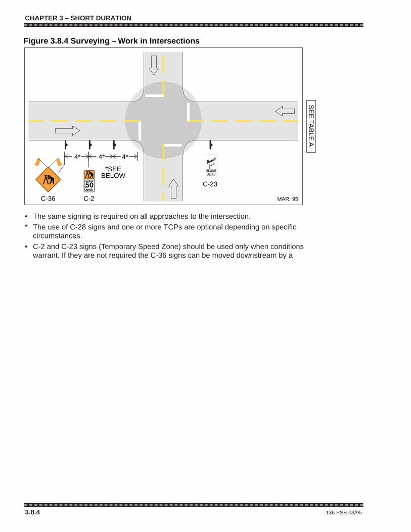
CHAPTER 3 – SHORT DURATION
3.8.4 136 PSB 03/95
C-36 C-2
*SEEBELOW
4*4* 4*
SE
E TA
BLE
A
C-23
Figure 3.8.4 Surveying – Work in Intersections
MAR. 95
• The same signing is required on all approaches to the intersection.
* The use of C-28 signs and one or more TCPs are optional depending on specificcircumstances.
• C-2 and C-23 signs (Temporary Speed Zone) should be used only when conditionswarrant. If they are not required the C-36 signs can be moved downstream by a

CHAPTER 3 – SHORT DURATION
PSB 03/95 137 3.9 – 3.9.1
3.9 UTILITY WORK
GENERALIn most circumstances, traffic control required for utility work is nodifferent than that required for road construction or maintenance.
The following figures, however, illustrate traffic control for situationspeculiar to utility work.
MANHOLE GUARD
SE
E TA
BLE
A
C-4
1b*1b*
C-53
C-4
4*
4*
Figure 3.9.1 Utility Work on Centreline – Urban Area
HLWD
MAR. 95
• Additional advanced warning may be used if required.
• C-1 and C-23 signs (Temporary Speed Zone) may be used when conditions warrant.
• See Table for Figure 3.4.3.
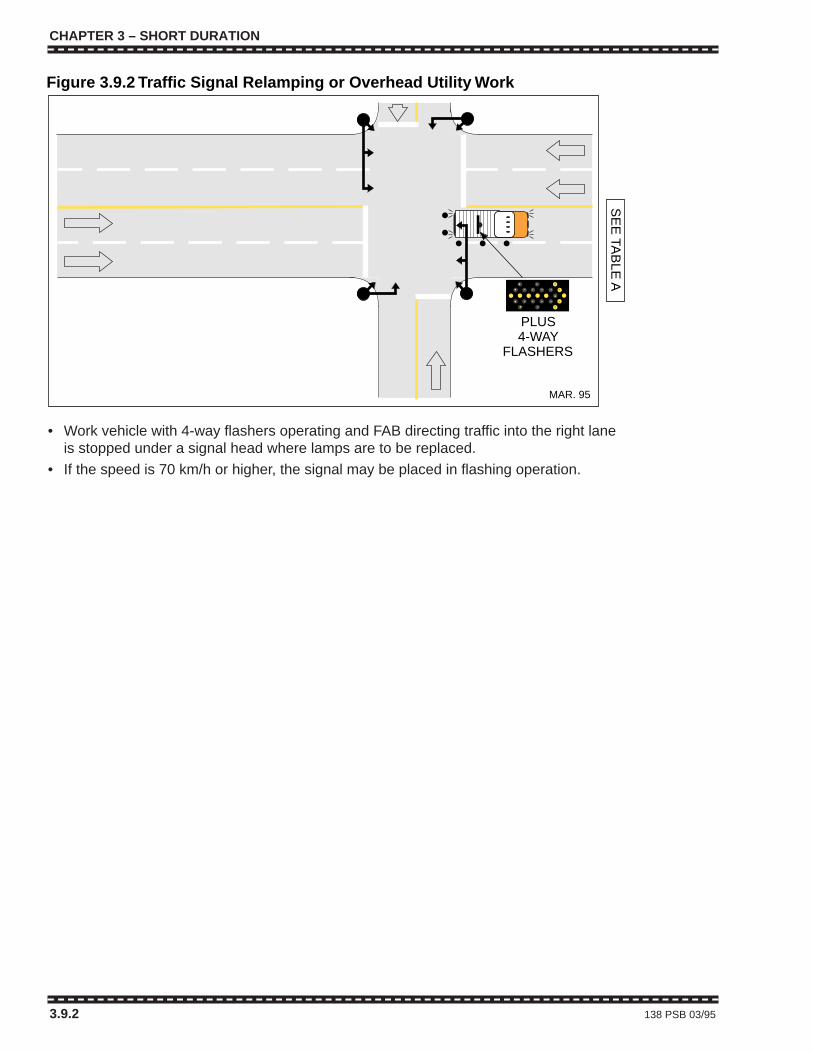
CHAPTER 3 – SHORT DURATION
3.9.2 138 PSB 03/95
PLUS4-WAY
FLASHERS
SE
E TA
BLE
A
Figure 3.9.2 Traffic Signal Relamping or Overhead Utility Work
MAR. 95
• Work vehicle with 4-way flashers operating and FAB directing traffic into the right laneis stopped under a signal head where lamps are to be replaced.
• If the speed is 70 km/h or higher, the signal may be placed in flashing operation.

CHAPTER 4 – LONG DURATION
1926 01/99 139 Legend
TUBULAR MARKER – TYPE D
CONE – TYPE A, B or C
SIGN
TRAFFIC CONTROL PERSON (TCP)
SHADOW, BUFFER or WORK VEHICLE
(360°) FLASHING YELLOW LIGHT
WORK AREA
PORTABLE LANE CONTROL SIGNAL
BARRICADES and FENCING
FLASHING ARROW BOARD (FAB)
HIGH LEVEL WARNING DEVICE (HLWD)
LEGEND
CHAPTER 4TYPICAL TRAFFIC CONTROL LAYOUTSFOR LONG DURATION WORK ZONES
Exception for Emergency and Brief Duration WorkIf the work being carried out is of an emergency or brief duration nature, as defined, andis within a speed limit of 60 km/h or less, it may not be practicable to provide the TCPsor advance signing called for in Chapters 3 and 4 of the Traffic Control Manual.
CHAPTER 4 – LONG DURATION
Table A 140 PSB 03/95
TABLE APositioning of devices on conventional roadways for various speed limits.
*Regulatory 50 60 70 80 90-100speed limit km/h km/h km/h km/h km/h
1aTaper length 35 55 75 90 110for lane closure (1:10) (1:15) (1:20) (1:25) (1:30)
Taper length
1bfor shoulder work
5 8 10 12 15or where TCPs used(min. 3 cones)
Maximum distance2 between cones 10 10 10 10 10
or tubular markersfor 1a
3Minimum tangent
30 60 90 120 150distance betweentapers
4Distance between
40 60 80 100 150construction signs
Dimensions shown are in metres and are minimums except for 2*.
Cones and tubular markers are generally used only in daylight but if used at night mustbe reflectorized. Barricades, flexible drums or temporary delineator posts are generallyused during hours of darkness and must be reflectorized.
Dimensions 1b* apply to downstream tapers, shoulder tapers, and to two-way traffictapers on travelled lanes where traffic is controlled by TCPs, portable lane controlsignals or temporary traffic signals.
Dimensions 4* represent the minimum advance placement distances for initial signs aswell as distances between subsequent signs in multi-sign series.
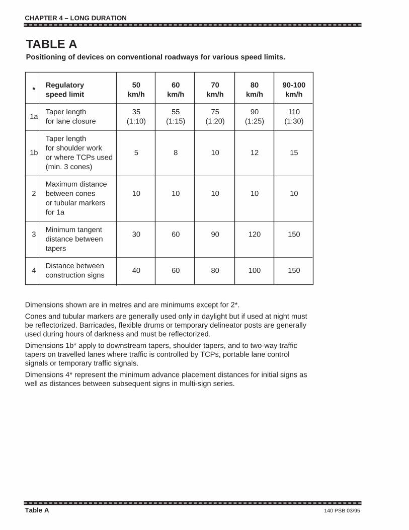
CHAPTER 4 – LONG DURATION
1926 01/99 139 Legend
TUBULAR MARKER – TYPE D
CONE – TYPE A, B or C
SIGN
TRAFFIC CONTROL PERSON (TCP)
SHADOW, BUFFER or WORK VEHICLE
(360°) FLASHING YELLOW LIGHT
WORK AREA
PORTABLE LANE CONTROL SIGNAL
BARRICADES and FENCING
FLASHING ARROW BOARD (FAB)
HIGH LEVEL WARNING DEVICE (HLWD)
LEGEND
CHAPTER 4TYPICAL TRAFFIC CONTROL LAYOUTSFOR LONG DURATION WORK ZONES
Exception for Emergency and Brief Duration WorkIf the work being carried out is of an emergency or brief duration nature, as defined, andis within a speed limit of 60 km/h or less, it may not be practicable to provide the TCPsor advance signing called for in Chapters 3 and 4 of the Traffic Control Manual.
CHAPTER 4 – LONG DURATION
Table A 140 PSB 03/95
TABLE APositioning of devices on conventional roadways for various speed limits.
*Regulatory 50 60 70 80 90-100speed limit km/h km/h km/h km/h km/h
1aTaper length 35 55 75 90 110for lane closure (1:10) (1:15) (1:20) (1:25) (1:30)
Taper length
1bfor shoulder work
5 8 10 12 15or where TCPs used(min. 3 cones)
Maximum distance2 between cones 10 10 10 10 10
or tubular markersfor 1a
3Minimum tangent
30 60 90 120 150distance betweentapers
4Distance between
40 60 80 100 150construction signs
Dimensions shown are in metres and are minimums except for 2*.
Cones and tubular markers are generally used only in daylight but if used at night mustbe reflectorized. Barricades, flexible drums or temporary delineator posts are generallyused during hours of darkness and must be reflectorized.
Dimensions 1b* apply to downstream tapers, shoulder tapers, and to two-way traffictapers on travelled lanes where traffic is controlled by TCPs, portable lane controlsignals or temporary traffic signals.
Dimensions 4* represent the minimum advance placement distances for initial signs aswell as distances between subsequent signs in multi-sign series.
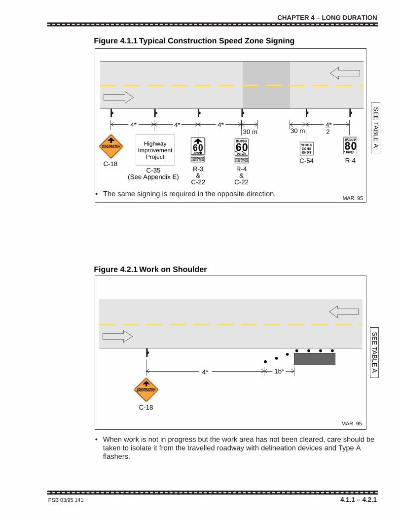
CHAPTER 4 – LONG DURATION
PSB 03/95 141 4.1.1 – 4.2.1
R-3&
C-22
C-54
30 m 30 m
R-4&
C-22
4*4*
SE
E TA
BLE
A
C-18
4*
Figure 4.1.1 Typical Construction Speed Zone Signing
MAR. 95
R-4
4*2
HighwayImprovement
Project
C-35(See Appendix E)
• The same signing is required in the opposite direction.
• When work is not in progress but the work area has not been cleared, care should betaken to isolate it from the travelled roadway with delineation devices and Type Aflashers.
4* 1b*
SE
E TA
BLE
A
C-18
Figure 4.2.1 Work on Shoulder
MAR. 95
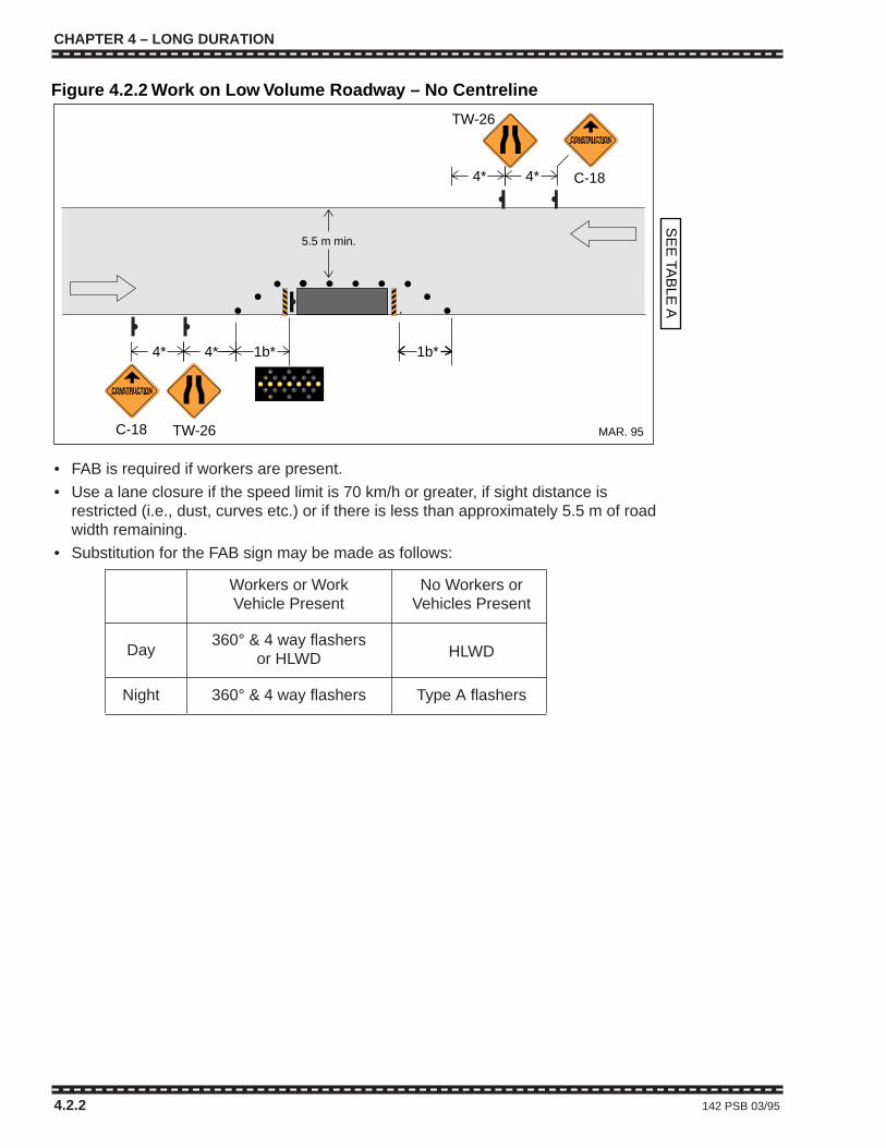
CHAPTER 4 – LONG DURATION
4.2.2 142 PSB 03/95
1b*4* 4*
TW-26
4*
SE
E TA
BLE
A
C-18
C-18
TW-26
4*
Figure 4.2.2 Work on Low Volume Roadway – No Centreline
MAR. 95
1b*
5.5 m min.
• FAB is required if workers are present.
• Use a lane closure if the speed limit is 70 km/h or greater, if sight distance isrestricted (i.e., dust, curves etc.) or if there is less than approximately 5.5 m of roadwidth remaining.
• Substitution for the FAB sign may be made as follows:
Workers or Work No Workers orVehicle Present Vehicles Present
Day360° & 4 way flashers
HLWDor HLWD
Night 360° & 4 way flashers Type A flashers
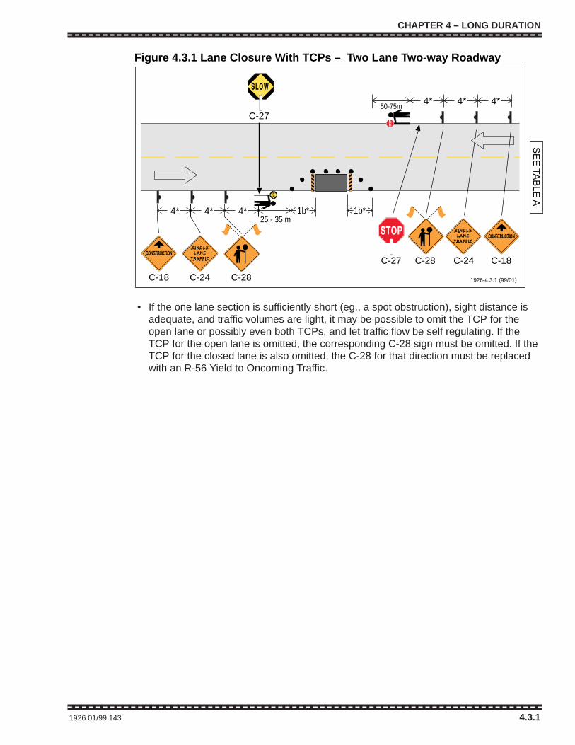
CHAPTER 4 – LONG DURATION
1926 01/99 143 4.3.1
C-24 C-28
C-24C-28
50-75m
4*4*
4* 4*4*
4*
C-27
C-27
SE
E TA
BLE
A
C-18
C-18
Figure 4.3.1 Lane Closure With TCPs – Two Lane Two-way Roadway
1926-4.3.1 (99/01)
1b*1b*25 - 35 m
• If the one lane section is sufficiently short (eg., a spot obstruction), sight distance isadequate, and traffic volumes are light, it may be possible to omit the TCP for theopen lane or possibly even both TCPs, and let traffic flow be self regulating. If theTCP for the open lane is omitted, the corresponding C-28 sign must be omitted. If theTCP for the closed lane is also omitted, the C-28 for that direction must be replacedwith an R-56 Yield to Oncoming Traffic.
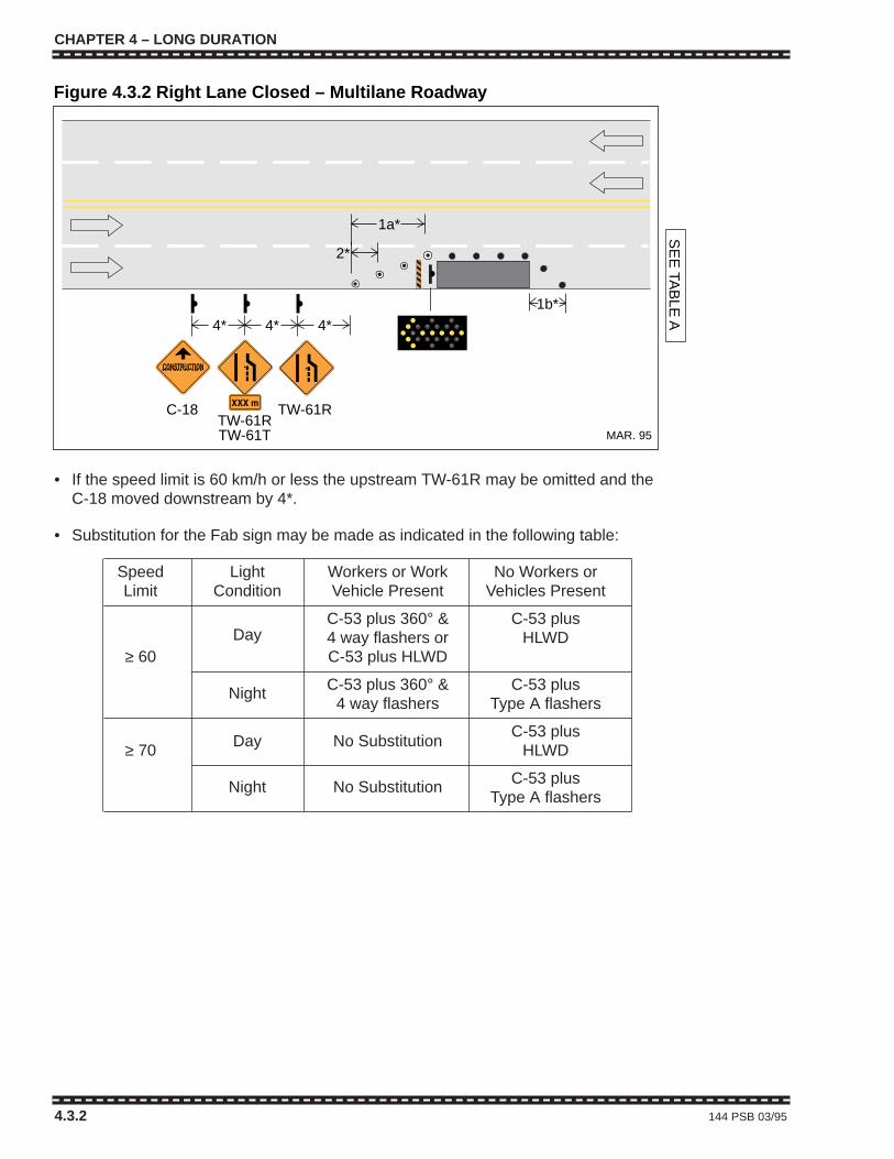
CHAPTER 4 – LONG DURATION
4.3.2 144 PSB 03/95
C-18
4*4*4*
2*
TW-61RTW-61RTW-61T
1a*
Figure 4.3.2 Right Lane Closed – Multilane Roadway
MAR. 95
SE
E TA
BLE
A
1b*
• If the speed limit is 60 km/h or less the upstream TW-61R may be omitted and the C-18 moved downstream by 4*.
• Substitution for the Fab sign may be made as indicated in the following table:
Speed Light Workers or Work No Workers orLimit Condition Vehicle Present Vehicles Present
DayC-53 plus 360° & C-53 plus4 way flashers or HLWD
≥ 60 C-53 plus HLWD
Night C-53 plus 360° & C-53 plus4 way flashers Type A flashers
Day No SubstitutionC-53 plus
≥ 70 HLWD
Night No Substitution C-53 plusType A flashers

CHAPTER 4 – LONG DURATION
PSB 03/95 145 4.3.3 – 4.3.4
• For high volume roads, concrete barriers may be considered to separate opposingtraffic.
• See footnotes on Fig. 4.3.2.
C-18
4*1a* 4*4*1a*
4* 1a* 1a*4* 4* 3*
2*
C-18TW-61LTW-61T
TW-61L
TW-61RTW-61T TW-61R
C-53
SE
E TA
BLE
A
MAR. 95
Figure 4.3.4 Median Crossover – Multilane Roadway
2 x 1b*
C-53
C-18 TW-61LTW-61LTW-61T
4*4*4*
1a*
2*
SE
E TA
BLE
A
Figure 4.3.3 Left Lane Closed – Multilane Roadway
1b*
MAR. 95• See footnotes
on Fig. 4.3.2.
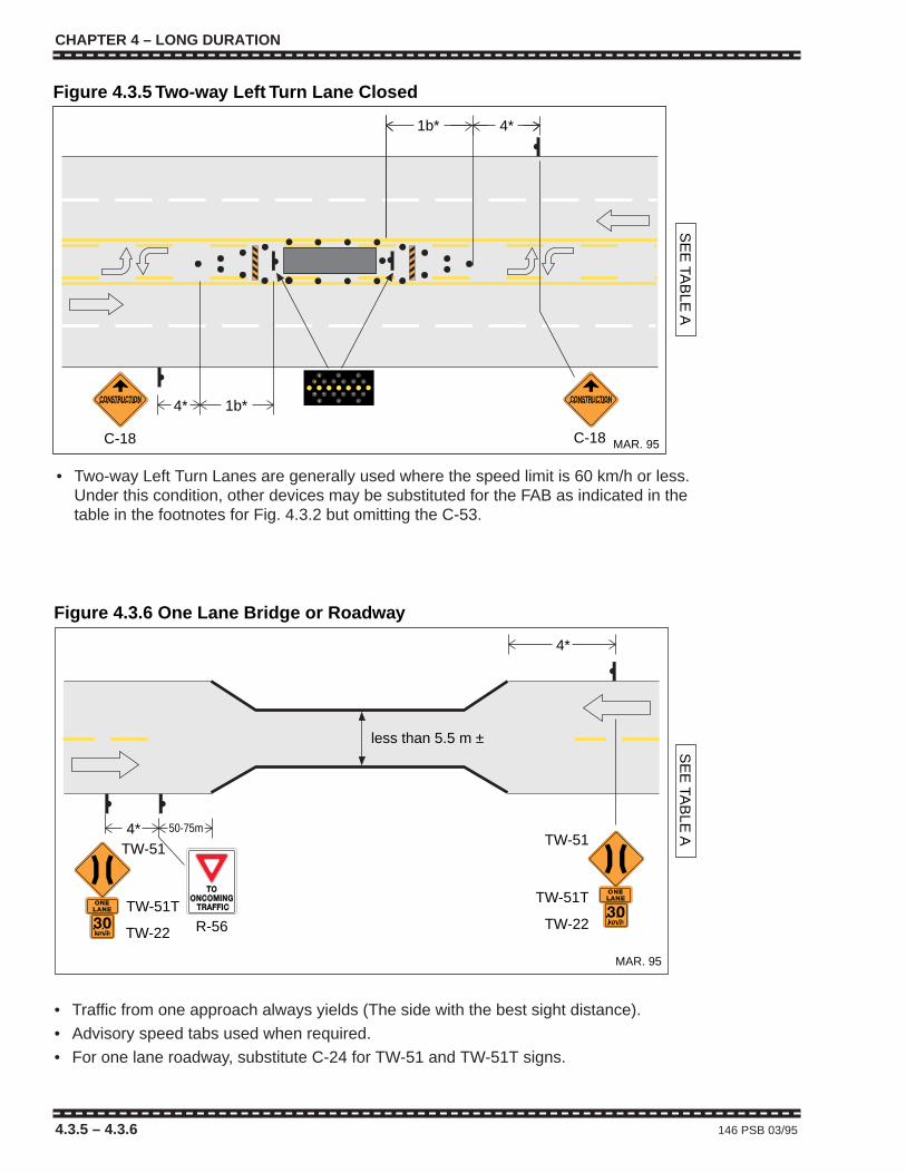
CHAPTER 4 – LONG DURATION
4.3.5 – 4.3.6 146 PSB 03/95
1b*
4*1b*
4*
SE
E TA
BLE
A
C-18 C-18
Figure 4.3.5 Two-way Left Turn Lane Closed
MAR. 95
4*
4*TW-51
TW-51T
TW-22
SE
E TA
BLE
A
R-56
TW-51
TW-51T
TW-22
50-75m
MAR. 95
Figure 4.3.6 One Lane Bridge or Roadway
less than 5.5 m ±
• Traffic from one approach always yields (The side with the best sight distance).
• Advisory speed tabs used when required.
• For one lane roadway, substitute C-24 for TW-51 and TW-51T signs.
• Two-way Left Turn Lanes are generally used where the speed limit is 60 km/h or less.Under this condition, other devices may be substituted for the FAB as indicated in thetable in the footnotes for Fig. 4.3.2 but omitting the C-53.
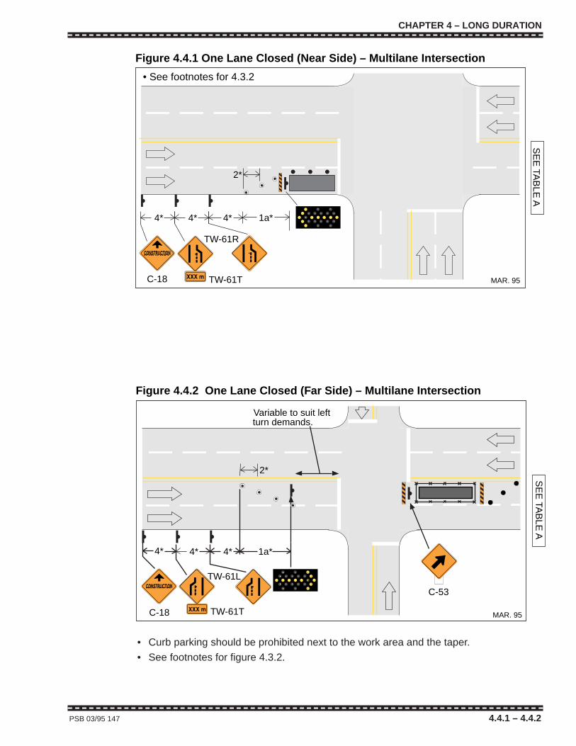
CHAPTER 4 – LONG DURATION
PSB 03/95 147 4.4.1 – 4.4.2
2*
SE
E TA
BLE
A
4*4* 4* 1a*
Variable to suit left turn demands.
C-18
TW-61L
TW-61T MAR. 95
Figure 4.4.2 One Lane Closed (Far Side) – Multilane Intersection
C-53
1a*4*4* 4*
C-18
TW-61R
2*
SE
E TA
BLE
A
TW-61T MAR. 95
Figure 4.4.1 One Lane Closed (Near Side) – Multilane Intersection
• See footnotes for 4.3.2
• Curb parking should be prohibited next to the work area and the taper.
• See footnotes for figure 4.3.2.
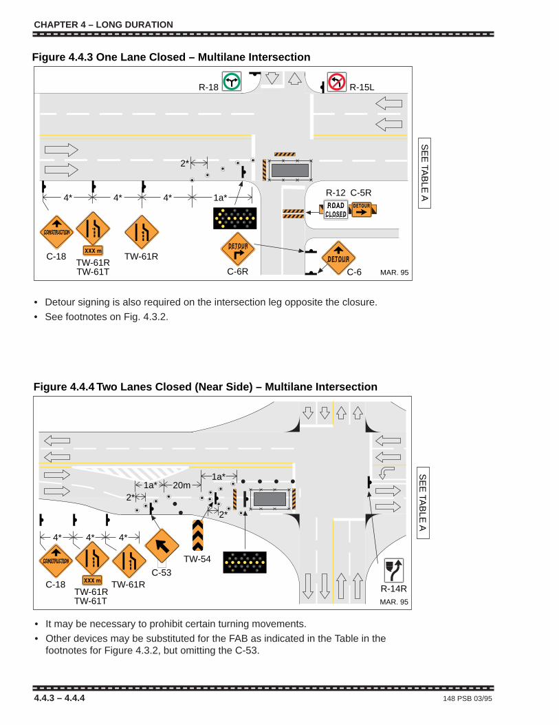
CHAPTER 4 – LONG DURATION
4.4.3 – 4.4.4 148 PSB 03/95
TW-61RTW-61T
TW-61R
1a*
MAR. 95
4* 4*4*
C-6C-6R
R-15L
2*
R-18
SE
E TA
BLE
A
C-18
R-12 C-5R
Figure 4.4.3 One Lane Closed – Multilane Intersection
• Detour signing is also required on the intersection leg opposite the closure.
• See footnotes on Fig. 4.3.2.
4*4*4*
R-14R
20m
2*
2*
1a*
C-18TW-61RTW-61T
SE
E TA
BLE
A
1a*
TW-61R
TW-54
C-53
MAR. 95
Figure 4.4.4 Two Lanes Closed (Near Side) – Multilane Intersection
• It may be necessary to prohibit certain turning movements.
• Other devices may be substituted for the FAB as indicated in the Table in thefootnotes for Figure 4.3.2, but omitting the C-53.

CHAPTER 4 – LONG DURATION
PSB 03/95 149 4.5.1 – 4.5.2
R-12 C-5R
MAR. 95
4* 4*
SE
E TA
BLE
A
Figure 4.5.2 One Lane Closed (Near Side)Figure 4.5.2 – Two Lane Two-way Intersection
C-6 C-6R
• This layout is to be used if an alternate route detour is available; if not, TCPs arerequired and the layout shown in Figure 4.3.1 should be used.
• If the diversion is paved, temporary pavement markings are required.
• Similar signing is required for opposing traffic.
MAR. 95
4*4*
TW-62As required
TW-49If required
TW-22If required
C-18C-52R
SE
E TA
BLE
A
DELINEATORS
R-12 C-5R
Figure 4.5.1 Roadside Diversion – Two Lane Two-way Roadway
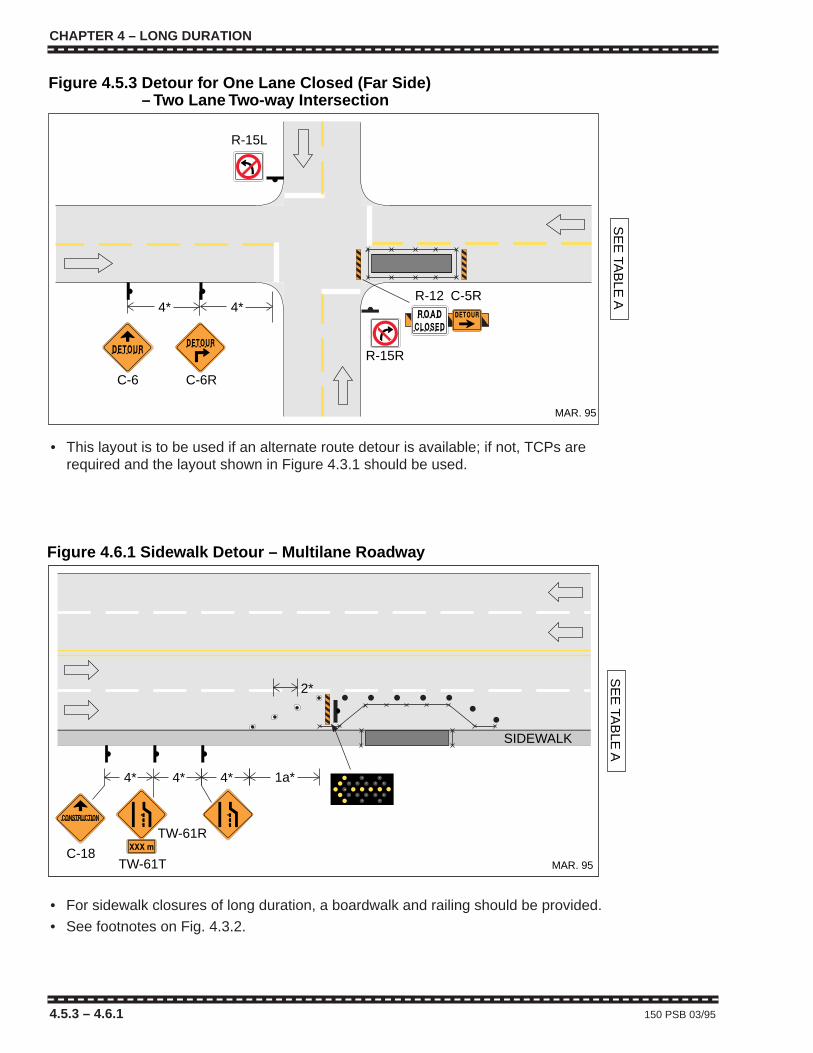
CHAPTER 4 – LONG DURATION
4.5.3 – 4.6.1 150 PSB 03/95
MAR. 95
4*
2*
4* 1a*
SIDEWALK
SE
E TA
BLE
A
C-18
4*
TW-61T
TW-61R
Figure 4.6.1 Sidewalk Detour – Multilane Roadway
• For sidewalk closures of long duration, a boardwalk and railing should be provided.
• See footnotes on Fig. 4.3.2.
R-15L
R-12 C-5R
MAR. 95
4* 4*
SE
E TA
BLE
A
Figure 4.5.3 Detour for One Lane Closed (Far Side)Figure 4.5.3 – Two Lane Two-way Intersection
C-6 C-6R
R-15R
• This layout is to be used if an alternate route detour is available; if not, TCPs arerequired and the layout shown in Figure 4.3.1 should be used.
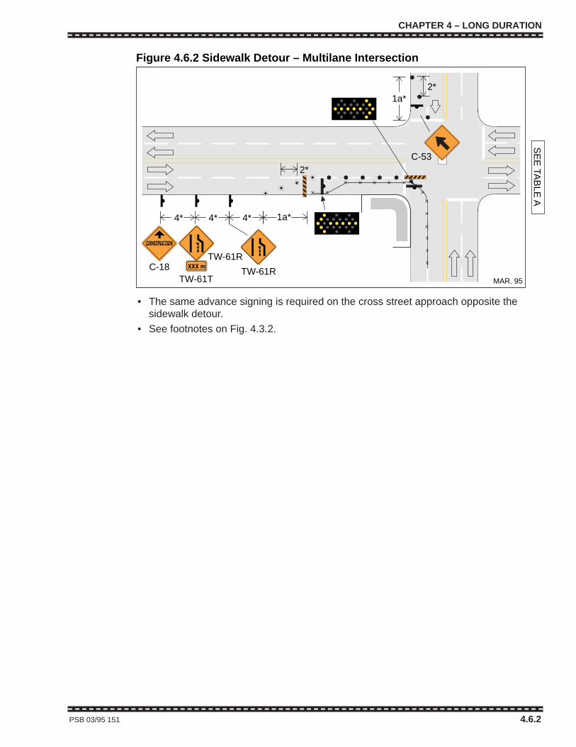
CHAPTER 4 – LONG DURATION
PSB 03/95 151 4.6.2
MAR. 95
C-18TW-61T
TW-61R
TW-61R
2*
1a*
1a*2*
SE
E TA
BLE
A
4* 4*4*
C-53
Figure 4.6.2 Sidewalk Detour – Multilane Intersection
• The same advance signing is required on the cross street approach opposite thesidewalk detour.
• See footnotes on Fig. 4.3.2.

CHAPTER 4 – LONG DURATION
152 PSB 03/95
CHAPTER 4 – LONG DURATION
152 PSB 03/95
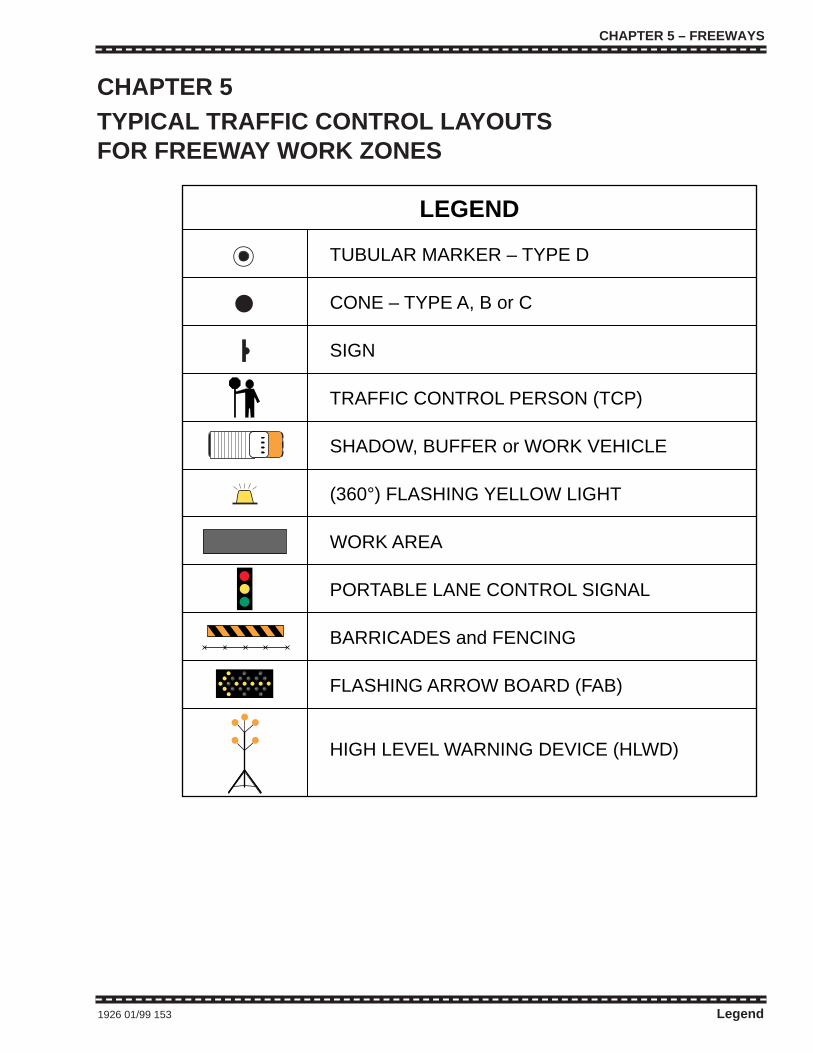
CHAPTER 5 – FREEWAYS
1926 01/99 153 Legend
TUBULAR MARKER – TYPE D
CONE – TYPE A, B or C
SIGN
TRAFFIC CONTROL PERSON (TCP)
SHADOW, BUFFER or WORK VEHICLE
(360°) FLASHING YELLOW LIGHT
WORK AREA
PORTABLE LANE CONTROL SIGNAL
BARRICADES and FENCING
FLASHING ARROW BOARD (FAB)
HIGH LEVEL WARNING DEVICE (HLWD)
LEGEND
CHAPTER 5TYPICAL TRAFFIC CONTROL LAYOUTSFOR FREEWAY WORK ZONES
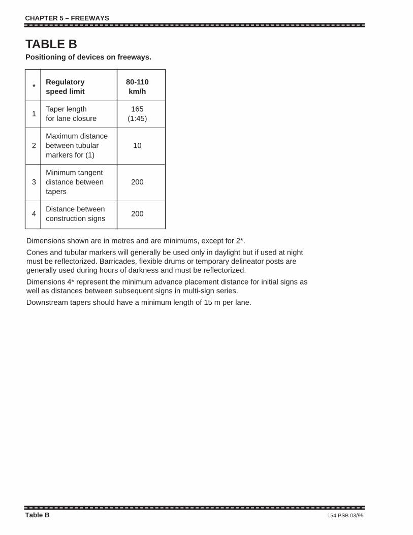
CHAPTER 5 – FREEWAYS
Table B 154 PSB 03/95
*Regulatory 80-110speed limit km/h
1Taper length 165for lane closure (1:45)
Maximum distance2 between tubular 10
markers for (1)
Minimum tangent3 distance between 200
tapers
4Distance between
200construction signs
Dimensions shown are in metres and are minimums, except for 2*.
Cones and tubular markers will generally be used only in daylight but if used at nightmust be reflectorized. Barricades, flexible drums or temporary delineator posts aregenerally used during hours of darkness and must be reflectorized.
Dimensions 4* represent the minimum advance placement distance for initial signs aswell as distances between subsequent signs in multi-sign series.
Downstream tapers should have a minimum length of 15 m per lane.
TABLE BPositioning of devices on freeways.
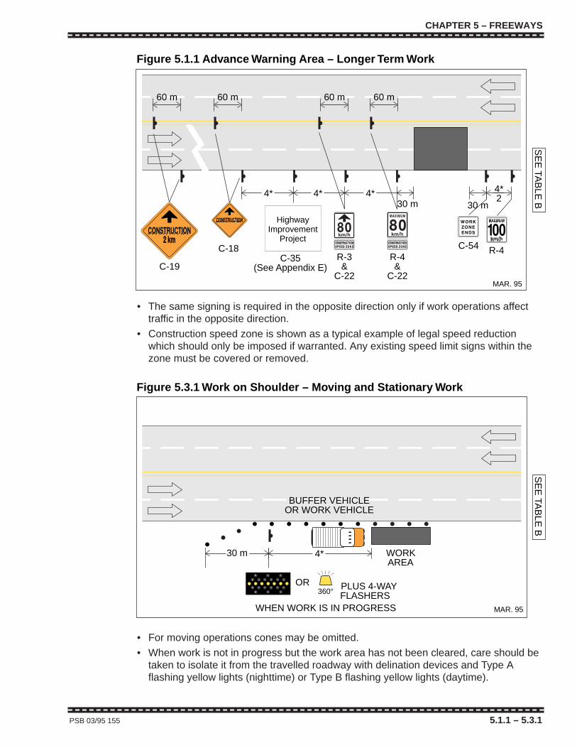
CHAPTER 5 – FREEWAYS
PSB 03/95 155 5.1.1 – 5.3.1
MAR. 95
C-54
30 m30 m
60 m60 m60 m60 m
SE
E TA
BLE
B
4* 4* 4*
C-18
C-19R-4&
C-22
R-3&
C-22
Figure 5.1.1 Advance Warning Area – Longer Term Work
4*2
R-4
HighwayImprovement
Project
C-35(See Appendix E)
MAR. 95
• The same signing is required in the opposite direction only if work operations affecttraffic in the opposite direction.
• Construction speed zone is shown as a typical example of legal speed reductionwhich should only be imposed if warranted. Any existing speed limit signs within thezone must be covered or removed.
SE
E TA
BLE
B
4*30 m WORK AREA
360°OR
MAR. 95
Figure 5.3.1 Work on Shoulder – Moving and Stationary Work
PLUS 4-WAYFLASHERS
WHEN WORK IS IN PROGRESS
BUFFER VEHICLEOR WORK VEHICLE
• For moving operations cones may be omitted.
• When work is not in progress but the work area has not been cleared, care should betaken to isolate it from the travelled roadway with delination devices and Type Aflashing yellow lights (nighttime) or Type B flashing yellow lights (daytime).
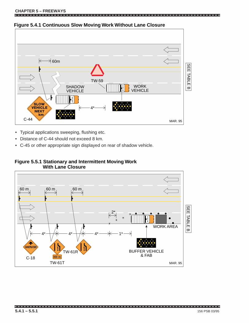
CHAPTER 5 – FREEWAYS
5.4.1 – 5.5.1 156 PSB 03/95
MAR. 95
SE
E TA
BLE
B60m
C-44
4*
Figure 5.4.1 Continuous Slow Moving Work Without Lane Closure
SHADOWVEHICLE
WORKVEHICLE
TW-59
• Typical applications sweeping, flushing etc.
• Distance of C-44 should not exceed 8 km.
• C-45 or other appropriate sign displayed on rear of shadow vehicle.
MAR. 95
SE
E TA
BLE
BWORK AREA
4* 4* 4*
C-18
TW-61R
TW-61T
2*
1*
BUFFER VEHICLE& FAB
Figure 5.5.1 Stationary and Intermittent Moving WorkFigure 5.5.1 With Lane Closure
60 m 60 m 60 m
CHAPTER 5 – FREEWAYS
5.4.1 – 5.5.1 156 PSB 03/95
MAR. 95
SE
E TA
BLE
B
60m
C-44
4*
Figure 5.4.1 Continuous Slow Moving Work Without Lane Closure
SHADOWVEHICLE
WORKVEHICLE
TW-59
• Typical applications sweeping, flushing etc.
• Distance of C-44 should not exceed 8 km.
• C-45 or other appropriate sign displayed on rear of shadow vehicle.
MAR. 95
SE
E TA
BLE
BWORK AREA
4* 4* 4*
C-18
TW-61R
TW-61T
2*
1*
BUFFER VEHICLE& FAB
Figure 5.5.1 Stationary and Intermittent Moving WorkFigure 5.5.1 With Lane Closure
60 m 60 m 60 m
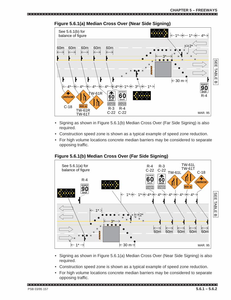
CHAPTER 5 – FREEWAYS
PSB 03/95 157 5.6.1 – 5.6.2
MAR. 95
SE
E TA
BLE
B
1* 4*1*
4* 1* 1*4* 4* 3*4*
R-3C-22
R-4
2*60m 60m 60m 60m
3*
4*
60m
R-4C-22
C-18
TW-61R
Figure 5.6.1(a) Median Cross Over (Near Side Signing)
30 m
See 5.6.1(b) forbalance of figure
TW-61RTW-61T
• Signing as shown in Figure 5.6.1(b) Median Cross Over (Far Side Signing) is alsorequired.
• Construction speed zone is shown as a typical example of speed zone reduction.
• For high volume locations concrete median barriers may be considered to separateopposing traffic.
MAR. 95
SE
E TA
BLE
B
1* 4* 4* 4* 4* 4*
60m60m60m60m60m
C-18TW-61L
R-3C-22
R-4C-22
TW-61LTW-61T
1*
1*2*
3*
R-4
Figure 5.6.1(b) Median Cross Over (Far Side Signing)
1* 30 m
See 5.6.1(a) forbalance of figure
• Signing as shown in Figure 5.6.1(a) Median Cross Over (Near Side Signing) is alsorequired.
• Construction speed zone is shown as a typical example of speed zone reduction.
• For high volume locations concrete median barriers may be considered to separateopposing traffic.
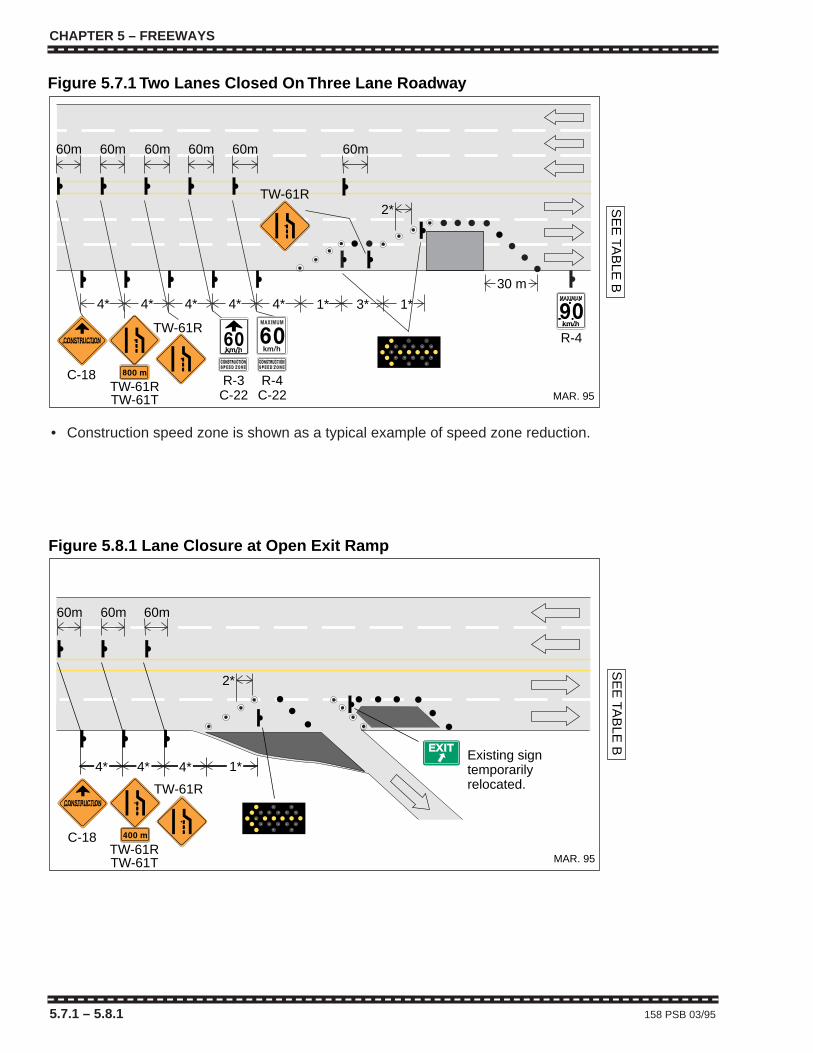
CHAPTER 5 – FREEWAYS
5.7.1 – 5.8.1 158 PSB 03/95
MAR. 95
1* 1*3*
2*
60m 60m 60m 60m60m 60m
SE
E TA
BLE
B
4* 4* 4*4*4*
R-3C-22
R-4C-22
C-18
TW-61R
TW-61R
R-4
Figure 5.7.1 Two Lanes Closed On Three Lane Roadway
30 m
TW-61RTW-61T
• Construction speed zone is shown as a typical example of speed zone reduction.
MAR. 95
SE
E TA
BLE
B
C-18
TW-61R
Figure 5.8.1 Lane Closure at Open Exit Ramp
4*4*4*
60m 60m 60m
1*
2*
Existing signtemporarilyrelocated.
TW-61RTW-61T
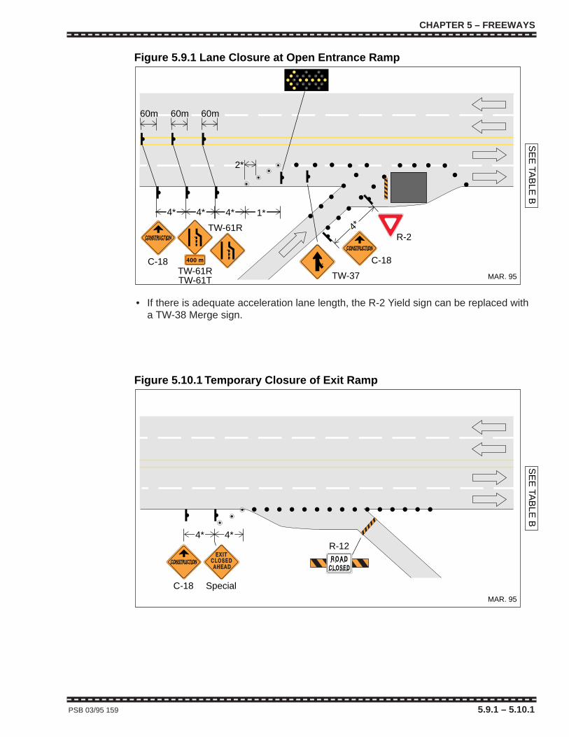
CHAPTER 5 – FREEWAYS
PSB 03/95 159 5.9.1 – 5.10.1
MAR. 95
SE
E TA
BLE
B
TW-37
C-18 C-18
R-2TW-61R
Figure 5.9.1 Lane Closure at Open Entrance Ramp
4*4*4*
4*
2*
TW-61RTW-61T
1*
60m 60m 60m
• If there is adequate acceleration lane length, the R-2 Yield sign can be replaced witha TW-38 Merge sign.
MAR. 95
SE
E TA
BLE
B
C-18
Figure 5.10.1 Temporary Closure of Exit Ramp
Special
R-124*4*

CHAPTER 5 – FREEWAYS
160 PSB 03/95
CHAPTER 5 – FREEWAYS
160 PSB 03/95
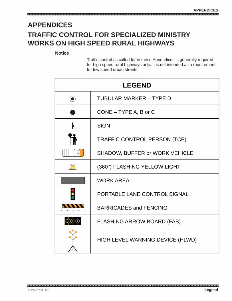
APPENDICES
APPENDICESTRAFFIC CONTROL FOR SPECIALIZED MINISTRYWORKS ON HIGH SPEED RURAL HIGHWAYS
NoticeTraffic control as called for in these Appendices is generally requiredfor high speed rural highways only. It is not intended as a requirementfor low speed urban streets.
1926 01/99 161 Legend
TUBULAR MARKER – TYPE D
CONE – TYPE A, B or C
SIGN
TRAFFIC CONTROL PERSON (TCP)
SHADOW, BUFFER or WORK VEHICLE
(360°) FLASHING YELLOW LIGHT
WORK AREA
PORTABLE LANE CONTROL SIGNAL
BARRICADES and FENCING
FLASHING ARROW BOARD (FAB)
HIGH LEVEL WARNING DEVICE (HLWD)
LEGEND
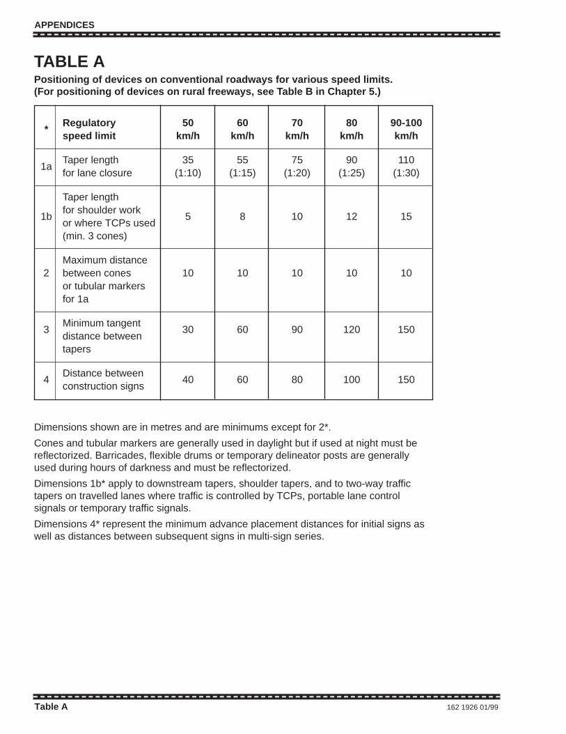
APPENDICES
Table A 162 1926 01/99
*Regulatory 50 60 70 80 90-100speed limit km/h km/h km/h km/h km/h
1aTaper length 35 55 75 90 110for lane closure (1:10) (1:15) (1:20) (1:25) (1:30)
Taper length
1bfor shoulder work
5 8 10 12 15or where TCPs used(min. 3 cones)
Maximum distance2 between cones 10 10 10 10 10
or tubular markersfor 1a
3Minimum tangent
30 60 90 120 150distance betweentapers
4Distance between
40 60 80 100 150construction signs
TABLE APositioning of devices on conventional roadways for various speed limits.(For positioning of devices on rural freeways, see Table B in Chapter 5.)
Dimensions shown are in metres and are minimums except for 2*.
Cones and tubular markers are generally used in daylight but if used at night must bereflectorized. Barricades, flexible drums or temporary delineator posts are generallyused during hours of darkness and must be reflectorized.
Dimensions 1b* apply to downstream tapers, shoulder tapers, and to two-way traffictapers on travelled lanes where traffic is controlled by TCPs, portable lane controlsignals or temporary traffic signals.
Dimensions 4* represent the minimum advance placement distances for initial signs aswell as distances between subsequent signs in multi-sign series.
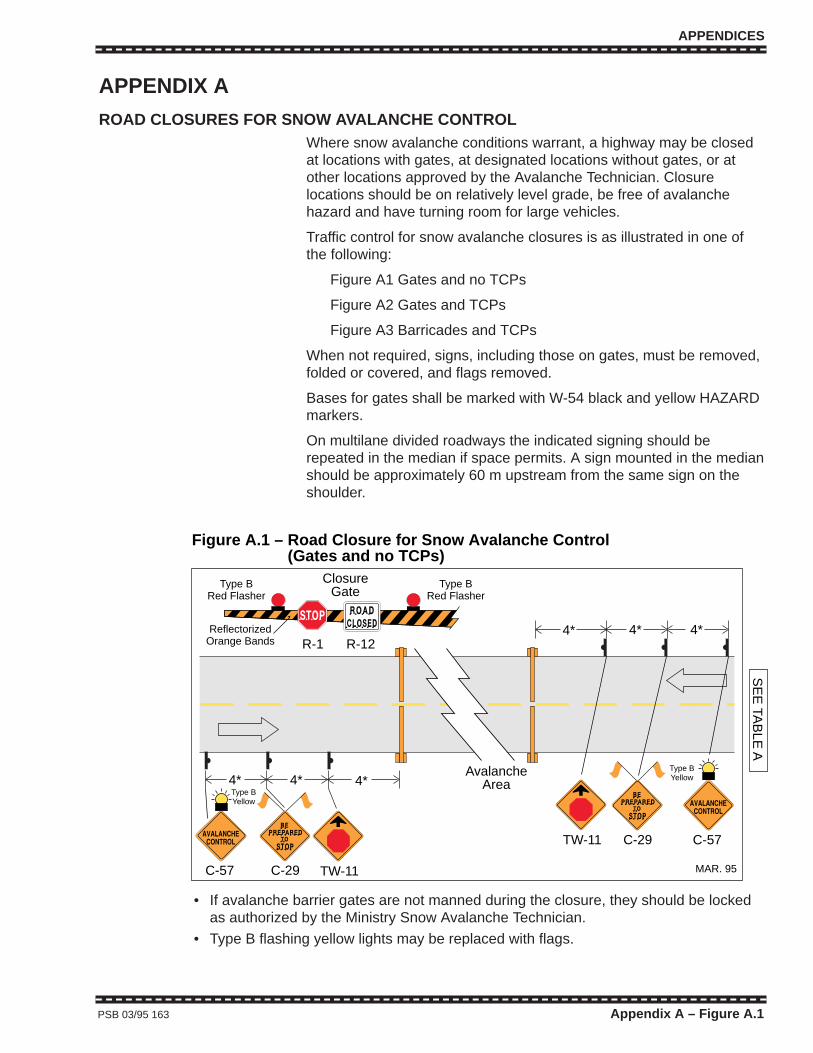
APPENDICES
PSB 03/95 163 Appendix A – Figure A.1
Figure A.1 – Road Closure for Snow Avalanche ControlFigure A.1 – (Gates and no TCPs)
MAR. 95S
EE
TAB
LE A
4* 4* 4*
C-57 TW-11
TW-11
4* 4*4*R-1
ReflectorizedOrange Bands
Type BRed Flasher
Type BRed Flasher
ClosureGate
R-12
C-57
Type BYellow
Type BYellow
C-29
C-29
AvalancheArea
• If avalanche barrier gates are not manned during the closure, they should be lockedas authorized by the Ministry Snow Avalanche Technician.
• Type B flashing yellow lights may be replaced with flags.
APPENDIX A
ROAD CLOSURES FOR SNOW AVALANCHE CONTROLWhere snow avalanche conditions warrant, a highway may be closedat locations with gates, at designated locations without gates, or atother locations approved by the Avalanche Technician. Closurelocations should be on relatively level grade, be free of avalanchehazard and have turning room for large vehicles.
Traffic control for snow avalanche closures is as illustrated in one ofthe following:
Figure A1 Gates and no TCPs
Figure A2 Gates and TCPs
Figure A3 Barricades and TCPs
When not required, signs, including those on gates, must be removed,folded or covered, and flags removed.
Bases for gates shall be marked with W-54 black and yellow HAZARDmarkers.
On multilane divided roadways the indicated signing should berepeated in the median if space permits. A sign mounted in the medianshould be approximately 60 m upstream from the same sign on theshoulder.
APPENDICES
PSB 03/95 163 Appendix A – Figure A.1
Figure A.1 – Road Closure for Snow Avalanche ControlFigure A.1 – (Gates and no TCPs)
MAR. 95
SE
E TA
BLE
A
4* 4* 4*
C-57 TW-11
TW-11
4* 4*4*R-1
ReflectorizedOrange Bands
Type BRed Flasher
Type BRed Flasher
ClosureGate
R-12
C-57
Type BYellow
Type BYellow
C-29
C-29
AvalancheArea
• If avalanche barrier gates are not manned during the closure, they should be lockedas authorized by the Ministry Snow Avalanche Technician.
• Type B flashing yellow lights may be replaced with flags.
APPENDIX A
ROAD CLOSURES FOR SNOW AVALANCHE CONTROLWhere snow avalanche conditions warrant, a highway may be closedat locations with gates, at designated locations without gates, or atother locations approved by the Avalanche Technician. Closurelocations should be on relatively level grade, be free of avalanchehazard and have turning room for large vehicles.
Traffic control for snow avalanche closures is as illustrated in one ofthe following:
Figure A1 Gates and no TCPs
Figure A2 Gates and TCPs
Figure A3 Barricades and TCPs
When not required, signs, including those on gates, must be removed,folded or covered, and flags removed.
Bases for gates shall be marked with W-54 black and yellow HAZARDmarkers.
On multilane divided roadways the indicated signing should berepeated in the median if space permits. A sign mounted in the medianshould be approximately 60 m upstream from the same sign on theshoulder.

Figure A.2 – Road Closure for Snow Avalanche ControlFigure A.2 – (Gates and TCPs)
1926-A.2 (99/01)
SE
E TA
BLE
A
4* 4*
C-57
R-14* 4*4*Reflectorized
Orange Bands
Type BRed Flasher
Type BRed Flasher
ClosureGate
R-12
4*
25-35 m
25-35 m
C-27
C-27 C-57
Type BYellow
AvalancheArea
C-28C-29
Type BYellow
C-28C-29
• Type B flashing yellow lights may be replaced with flags.
APPENDICES
Appendix A – Figures A.2 – A.3 164 1926 01/99
Figure A.3 – Road Closure for Snow Avalanche ControlFigure A.3 – (Barricades and TCPs)
1926-A.3 (99/01)
SE
E TA
BLE
A
4* 4*
C-57 C-28
C-29
4* 4*4*
Type A flashing yellow lightsare required on barricadesduring hours of darkness
4*
25-35 m
C-29 C-27
C-27
Type BYellow
C-57
25-35 m
C-28
Type BYellowAvalanche
Area
• Roads may be closed for snow avalanche control (with barricades and TCPs) atungated locations approved by the Avalanche Technician.
• Type B flashing yellow lights may be replaced with flags.

APPENDICES
PSB 03/94 165 Appendix B
APPENDIX B
PAVEMENT MARKINGA document titled “Roadmarking Procedures” dated March 31, 1981and subsequent revisions describes procedures and equipmentrequired when marking is carried out on roads under the jurisdiction ofthe Ministry of Transportation and Highways. In addition, the followingfigures show recommended traffic control for the most common ruralmarking procedures.
Two Lane Two-way Rural RoadwayFigure B.1 indicates traffic control for painting centreline on a two lanetwo-way rural road.
Multilane Rural RoadwayFigure B.2 indicates traffic control for painting pavement markings on amultilane rural road.
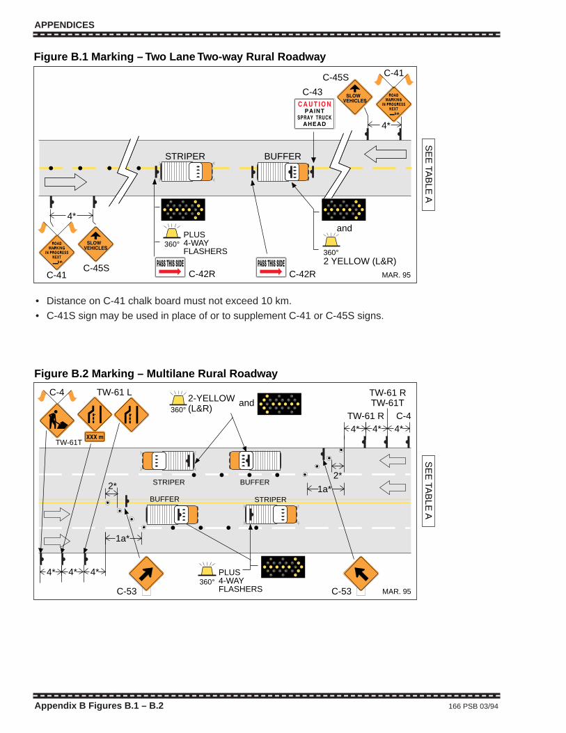
C-45SC-41
4*
STRIPER BUFFER
4*
SE
E TA
BLE
A
C-42R C-42R
C-45S C-41
C-43
2 YELLOW (L&R)360°
and
Figure B.1 Marking – Two Lane Two-way Rural Roadway
MAR. 95
360°PLUS4-WAYFLASHERS
• Distance on C-41 chalk board must not exceed 10 km.
• C-41S sign may be used in place of or to supplement C-41 or C-45S signs.
SE
E TA
BLE
A
2*
TW-61T
BUFFER STRIPER
1a*
BUFFERSTRIPER2*
TW-61 R
1a*
4*
TW-61 L TW-61 RTW-61T
4* 4*C-4
C-4
4* 4* 4*
C-53 C-53
2-YELLOW(L&R)360°
Figure B.2 Marking – Multilane Rural Roadway
and
MAR. 95360°
PLUS4-WAYFLASHERS
APPENDICES
Appendix B Figures B.1 – B.2 166 PSB 03/94
APPENDICES
PSB 03/94 167 Appendix C
APPENDIX C
FALLING WEIGHT DEFLECTOMETERThis pavement testing device is mounted on a smalltrailer towed by a van. The test unit typically stops for amaximum of 45 seconds per test and does not requirepersonnel to leave the vehicle. Test are usually taken atintervals of between 20 m and 100 m.
On two lane tow-way roadways with light traffic volumesand good visibility, traffic control as illustrated in Figure3.2.2 (with C-38 sign in place of a C-44) may be used. Iftraffic volumes are high or visibility poor, traffic controlas illustrated in Figure 3.2.1 should be used.
On multilane roadways traffic control as illustrated inFigure 3.2.3 (with a C-38 sign in place of a C-44) maybe used provided that the speed limit is 70 km/h orhigher, a shadow vehicle must be used, and ifconsidered necessary a buffer vehicle as well.
C-38 signs when used for Falling Weight Deflectometeroperations on rural highways may indicate a distancenot exceeding 8 km.

APPENDICES
Appendix C 168 PSB 03/94
APPENDICES
Appendix C 168 PSB 03/94

APPENDICES
PSB 03/94 169 Appendix D
APPENDIX D
PAVING AND SEALCOATING
GENERALPaving and sealcoating operations present a variety of traffic controlsituations which are frequently changing and constantly moving. It is,therefore, not practical to provide detailed traffic control proposals forall situations. Figures D.1 (a) and (b) and D.2 (a) and (b) illustrateminimum signing required for two typical situations.
If work is not in progress, and the roadway and shoulders are clear ofmachinery and obstructions, and the condition of the unfinishedroadway is such that traffic can proceed safely without the aid of TCPsor a pilot car, all non applicable signs should be removed or covered.If there are potential dangers such as loose gravel, dust , lowshoulders, bumps, fresh oil, uneven lifts of pavement, groovedpavement, no pavement markings, etc., then each should be signedaccordingly and the construction speed zone should be left in effect.
Particular attention should be given to signing for low shoulders anduneven lifts of pavement as they are not easily detected in darkness orpoor weather. On long sections, warning signs should be repeated asnecessary.
Construction speed zones should be altered as necessary to keepthem as short as possible and to not require drivers to proceed atunreasonably low speeds. Long zones will require that R-4/C-22assemblies be repeated as necessary. The ends of construction speedzones are marked with R-4 signs showing normal speed limits.
Figure D.2(a) and (b) illustrates typical signing for a pilot car operation.This signing can be incorporated into that shown in Figure D.1(a) and(b).
Care must be taken to ensure that signs are moved to keep up withmoving paving and sealcoating operation.
If TCPs must be employed during hours of darkness and difficulty isexperienced getting traffic to stop, an oversized (75 cm x 75 cm) R-1 STOP sign may be placed on a barricade across the closed lanewhere the TCP is located.
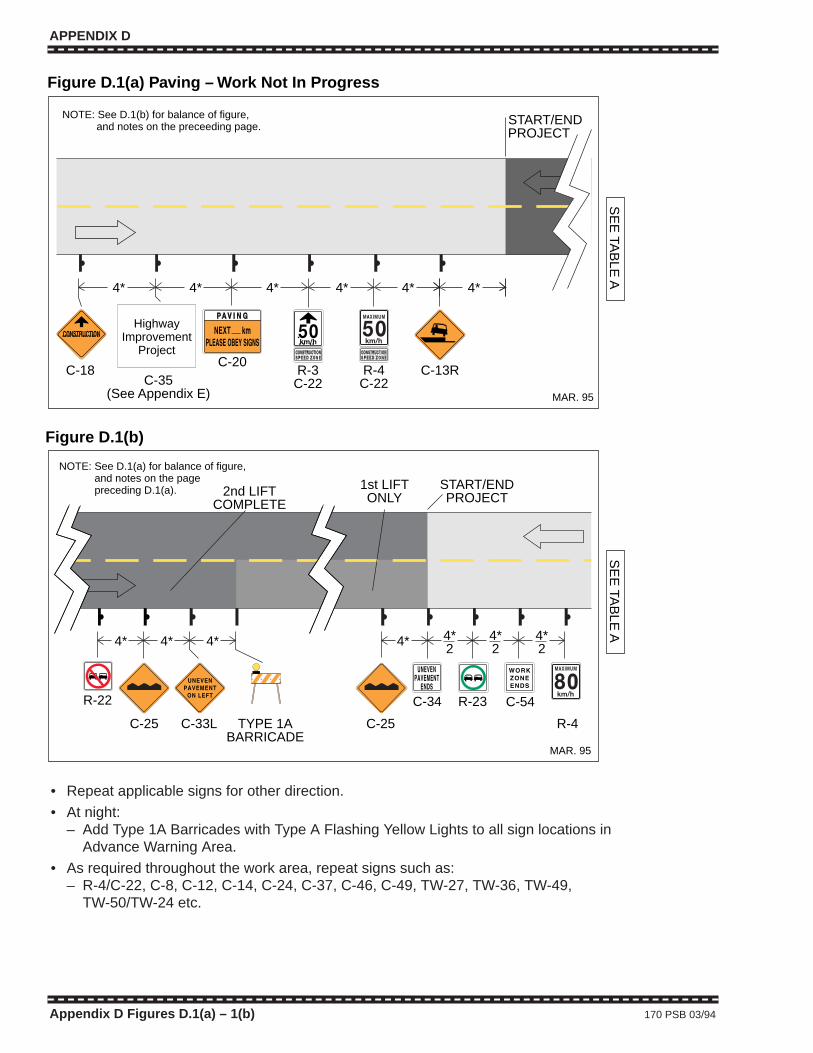
APPENDIX D
Appendix D Figures D.1(a) – 1(b) 170 PSB 03/94
MAR. 95
4*
SE
E TA
BLE
A
C-18
4* 4* 4* 4*
C-20R-3
C-22R-4
C-22
4*
C-13R
START/ENDPROJECT
Figure D.1(a) Paving – Work Not In Progress
NOTE: See D.1(b) for balance of figure, and notes on the preceeding page.
C-35(See Appendix E)
HighwayImprovement
Project
MAR. 95
SE
E TA
BLE
A
C-25
4*
R-22
4* 4*
TYPE 1ABARRICADE
START/ENDPROJECT
1st LIFTONLY2nd LIFT
COMPLETE
C-34 R-23 C-54
4*
R-4C-25 C-33L
Figure D.1(b)
4*2
4*2
4*2
NOTE: See D.1(a) for balance of figure, and notes on the page preceding D.1(a).
• Repeat applicable signs for other direction.
• At night:– Add Type 1A Barricades with Type A Flashing Yellow Lights to all sign locations in
Advance Warning Area.
• As required throughout the work area, repeat signs such as:– R-4/C-22, C-8, C-12, C-14, C-24, C-37, C-46, C-49, TW-27, TW-36, TW-49,
TW-50/TW-24 etc.
APPENDIX D
Appendix D Figures D.1(a) – 1(b) 170 PSB 03/94
MAR. 95
4*
SE
E TA
BLE
A
C-18
4* 4* 4* 4*
C-20R-3C-22
R-4C-22
4*
C-13R
START/ENDPROJECT
Figure D.1(a) Paving – Work Not In Progress
NOTE: See D.1(b) for balance of figure, and notes on the preceeding page.
C-35(See Appendix E)
HighwayImprovement
Project
MAR. 95
SE
E TA
BLE
A
C-25
4*
R-22
4* 4*
TYPE 1ABARRICADE
START/ENDPROJECT
1st LIFTONLY2nd LIFT
COMPLETE
C-34 R-23 C-54
4*
R-4C-25 C-33L
Figure D.1(b)
4*2
4*2
4*2
NOTE: See D.1(a) for balance of figure, and notes on the page preceding D.1(a).
• Repeat applicable signs for other direction.
• At night:– Add Type 1A Barricades with Type A Flashing Yellow Lights to all sign locations in
Advance Warning Area.
• As required throughout the work area, repeat signs such as:– R-4/C-22, C-8, C-12, C-14, C-24, C-37, C-46, C-49, TW-27, TW-36, TW-49,
TW-50/TW-24 etc.

APPENDIX D
1926 01/99 171 Appendix D Figures D.2(a) – D.2(b)
SE
E TA
BLE
A
C-27HLWD
optional 1296-D.2(a) (99/01)
C-18 C-21 R-3C-22
R-4C-22
C-24C-28
4* 4* 4* 4* 4* 4* 4*
25 -35 m
Figure D.2(a) Sealcoating in Progress
See M
atch LineF
igure D.2(b)
NOTE: See D.2(b) for balance of figure, and notes on the page following D.2(b).
C-35(See Appendix E)
HighwayImprovement
Project
MAR. 95
SE
E TA
BLE
A
Min. 20 m
C-46C-47
1b* 1b*
Figure D.2(b) Sealcoating in Progress
4*2
Min.20 m
C-54 R-4
See
Mat
ch L
ine
Fig
ure
D.2
(a)
NOTE: See D.2(a) for balance of figure, and notes on the following page.
• Repeat applicable signs for opposite direction.
• At night:– Add Type 1A Barricades with Type A Flashing Yellow Lights to all sign locations in
Advance Warning Area.– Add floodlights to illuminate TCPs station.
• As required throughout the work area:– Repeat signs such as R-4/C-22, C-4, C-14, C-37, C-46, C-49, TW-27, TW-36 etc.
• Every 5 km repeat C-21 sign showing decreasing distances.
• The pilot car operator and TCPs should be in radio contact.
APPENDIX D
1926 01/99 171 Appendix D Figures D.2(a) – D.2(b)
SE
E TA
BLE
A
C-27HLWD
optional 1296-D.2(a) (99/01)
C-18 C-21 R-3C-22
R-4C-22
C-24C-28
4* 4* 4* 4* 4* 4* 4*
25 -35 m
Figure D.2(a) Sealcoating in ProgressS
ee Match Line
Figure D
.2(b)
NOTE: See D.2(b) for balance of figure, and notes on the page following D.2(b).
C-35(See Appendix E)
HighwayImprovement
Project
MAR. 95
SE
E TA
BLE
A
Min. 20 m
C-46C-47
1b* 1b*
Figure D.2(b) Sealcoating in Progress
4*2
Min.20 m
C-54 R-4
See
Mat
ch L
ine
Fig
ure
D.2
(a)
NOTE: See D.2(a) for balance of figure, and notes on the following page.
• Repeat applicable signs for opposite direction.
• At night:– Add Type 1A Barricades with Type A Flashing Yellow Lights to all sign locations in
Advance Warning Area.– Add floodlights to illuminate TCPs station.
• As required throughout the work area:– Repeat signs such as R-4/C-22, C-4, C-14, C-37, C-46, C-49, TW-27, TW-36 etc.
• Every 5 km repeat C-21 sign showing decreasing distances.
• The pilot car operator and TCPs should be in radio contact.
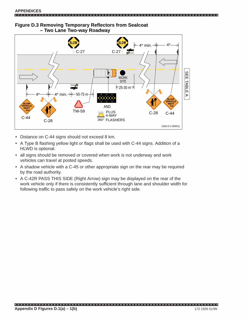
APPENDICES
Appendix D Figures D.1(a) – 1(b) 172 1926 01/99
4*
4*
C-28
TW-59
Figure D.3 Removing Temporary Reflectors from Sealcoat – Two Lane Two-way Roadway
1926-D.3 (99/01)
360°
PLUS4-WAYFLASHERS
SE
E TA
BLE
A
C-27 C-27
4* min.
4* min.
C-44C-44
50-75 m
AND
WORKSITE
25-30 m
C-28
• Distance on C-44 signs should not exceed 8 km.
• A Type B flashing yellow light or flags shall be used with C-44 signs. Addition of aHLWD is optional.
• all signs should be removed or covered when work is not underway and workvehicles can travel at posted speeds.
• A shadow vehicle with a C-45 or other appropriate sign on the rear may be requiredby the road authority.
• A C-42R PASS THIS SIDE (Right Arrow) sign may be displayed on the rear of thework vehicle only if there is consistently sufficient through lane and shoulder width forfollowing traffic to pass safely on the work vehicle’s right side.
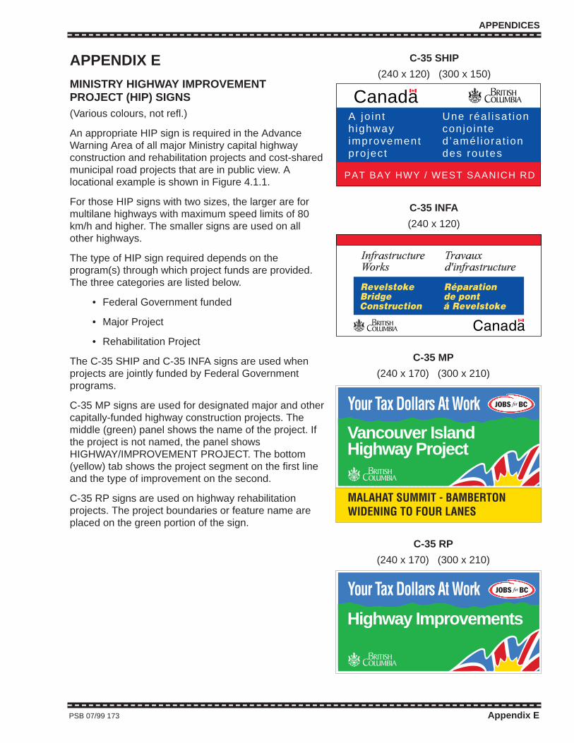
APPENDICES
PSB 07/99 173 Appendix E
APPENDIX E
MINISTRY HIGHWAY IMPROVEMENTPROJECT (HIP) SIGNS(Various colours, not refl.)
An appropriate HIP sign is required in the AdvanceWarning Area of all major Ministry capital highwayconstruction and rehabilitation projects and cost-sharedmunicipal road projects that are in public view. Alocational example is shown in Figure 4.1.1.
For those HIP signs with two sizes, the larger are formultilane highways with maximum speed limits of 80km/h and higher. The smaller signs are used on allother highways.
The type of HIP sign required depends on theprogram(s) through which project funds are provided.The three categories are listed below.
• Federal Government funded
• Major Project
• Rehabilitation Project
The C-35 SHIP and C-35 INFA signs are used whenprojects are jointly funded by Federal Governmentprograms.
C-35 MP signs are used for designated major and othercapitally-funded highway construction projects. Themiddle (green) panel shows the name of the project. Ifthe project is not named, the panel showsHIGHWAY/IMPROVEMENT PROJECT. The bottom(yellow) tab shows the project segment on the first lineand the type of improvement on the second.
C-35 RP signs are used on highway rehabilitationprojects. The project boundaries or feature name areplaced on the green portion of the sign.
C-35 SHIP
(240 x 120) (300 x 150)
C-35 INFA
(240 x 120)
A jo in th ighwayimprovementpro ject
Une réa l isat ionconjo in ted ’amél iorat iondes routes
PAT BAY HWY / WEST SAANICH RD
Canada
C-35 MP
(240 x 170) (300 x 210)
MALAHAT SUMMIT - BAMBERTONWIDENING TO FOUR LANES
Vancouver IslandHighway Project
C-35 RP
(240 x 170) (300 x 210)
Highway Improvements
RevelstokeBridgeConstruction
Réparationde pontá Revelstoke

APPENDICES
Appendix E 174 PSB 03/95
APPENDICES
Appendix E 174 PSB 03/95