Embed Size (px)
Citation preview

INDIANA DEPARTMENT OF TRANSPORTATION—2013 DESIGN MANUAL
CHAPTER 83
Traffic Control Devices in a Construction Zone
Design Memorandum
Revision Date
Sections Affected
16-06 Mar. 2016 Section 83-5.0, Figure 83-5A
NOTE: This chapter is currently being re-written and its content will be included in Chapter 503 in the future.

Page 2 2013 Indiana Design Manual, Ch. 83
TABLE OF CONTENTS
TABLE OF CONTENTS ................................................................................................................ 2
LIST OF FIGURES ......................................................................................................................... 3
83-1.0 GENERAL .......................................................................................................................... 4 83-1.01 References .................................................................................................................... 4 83-1.02 MUTCD Context .......................................................................................................... 4 83-1.03 Official Action .............................................................................................................. 5
83-2.0 HIGHWAY SIGNS ............................................................................................................ 5 83-2.01 Sign-Legend Measurement Units ................................................................................. 5 83-2.02 Placement ..................................................................................................................... 6 83-2.03 Regulatory Signing ....................................................................................................... 6
83-2.03(01) Work-Zone and Work-Site Speed Limit Signing [Rev. June 2012] .................. 6 83-2.03(02) “Stop” or “Yield” Sign ....................................................................................... 8 83-2.03(03) Selective-Exclusion Sign ................................................................................... 8
83-2.04 Advance-Warning Sign ................................................................................................ 9 83-2.05 Guide Sign .................................................................................................................. 10 83-2.06 Portable Changeable Message Sign [Rev. May 2012] ............................................... 12
83-2.06(01) Need [Rev. May 2012] ..................................................................................... 12 83-2.06(02) Design Considerations [Rev. May 2012] ......................................................... 13 83-2.06(03) Plans Requirements [Added May 2012] .......................................................... 13 83-2.06(04) TMC Control of PCMS Operation [Added May 2012] ................................... 14
83-2.07 Flashing-Arrow Sign .................................................................................................. 15
83-3.0 CHANNELIZATION DEVICES ..................................................................................... 16 83-3.01 Types .......................................................................................................................... 16 83-3.02 Taper Length ............................................................................................................... 19 83-3.03 Spacing ....................................................................................................................... 19 83-3.04 Type III Barricade ....................................................................................................... 19
83-4.0 PAVEMENT MARKINGS .............................................................................................. 20 83-4.01 Types .......................................................................................................................... 20
83-4.01(01) Paint ................................................................................................................. 20 83-4.01(02) Temporary Raised Pavement Markers ............................................................. 21 83-4.01(03) Temporary Pavement-Marking Tape ............................................................... 21 83-4.01(04) Thermoplastic or Epoxy Markings ................................................................... 21 83-4.01(05) Buzz Strips ....................................................................................................... 22
83-4.02 Application ................................................................................................................. 22
83-5.0 TEMPORARY TRAFFIC SIGNAL [Rev. Mar. 2016] ..................................................... 22

2013 Indiana Design Manual, Ch. 83 Page 3
83-5.01 Location ....................................................................................................................... 22 83-5.02 Application [Rev. Mar. 2016] ..................................................................................... 23
83-6.0 HIGHWAY LIGHTING ................................................................................................... 26 83-6.01 Types .......................................................................................................................... 26 83-6.02 Warrants ..................................................................................................................... 26
FIGURES ...................................................................................................................................... 28 LIST OF FIGURES Figure Title 83-2A English to Metric Conversions 83-2B Suggested Freeway Speed Limits (Work Zones and Work Sites) 83-2C Advance Warning Signs 83-2D Suggested Use and Location of Flashing Arrow Signs 83-2E Programming Information for Portable Changeable Message Sign 83-3B Taper Length Criteria for Construction Zones 83-3C Taper Length Criteria for Construction Zones (Application) 83-3D Suggested Maximum Spacing of Channelization Devices 83-4A Buzz Strips 83-5A Vehicle Detection Typical Placement Areas [Added Mar. 2016]

Page 4 2013 Indiana Design Manual, Ch. 83
CHAPTER 83
TRAFFIC CONTROL DEVICES IN A CONSTRUCTION ZONE
83-1.0 GENERAL The proper use of traffic control devices is critical to both public and worker safety and has been proven to significantly reduce accidents in a construction zone. This Chapter provides supplemental information on these devices and provides specific Department policies and procedures. For additional information, the designer is encouraged to review the references listed in Section 83-1.01. 83-1.01 References For additional information on the design, application, and placement of traffic control devices in a work area, the designer is referred to the latest editions of the publications as follows: 1. Manual on Uniform Traffic Control Devices (MUTCD), FHWA; 2. INDOT Standard Drawings; 3. INDOT Standard Specifications; 4. Indiana Design Manual, Section 502-1.0 – Roadway Signing; 5. Indiana Design Manual, Section 502-2.0 – Pavement Markings; 6. Indiana Design Manual, Section 502-3.0 – Traffic Signals; 7. Indiana Design Manual, Section 502-4.0 – Highway Lighting. The INDOT publications can be obtained by contacting the Contract Administration Division. For other publications, the indicated source should be contacted. 83-1.02 MUTCD Context Throughout the MUTCD, the words shall, should, and may are used to describe the appropriate application each traffic-control device. The MUTCD defines the terms as follows: 1. Shall. A mandatory condition. Where certain requirements in the design or application of a
device are described with the “shall” stipulation, it is mandatory that if an installation is made that these requirements be met.

2013 Indiana Design Manual, Ch. 83 Page 5
2. Should. An advisory condition. Where the word should is used, it is considered to be
advisable usage, recommended but not mandatory. 3. May. A permissive condition. No requirement for design or application is intended. 83-1.03 Official Action An Official Action is required before installing a regulatory temporary traffic control device, if a proposed change is made to a facility’s regulatory control. For example, an Official Action is required where a proposed change is made regarding a parking restriction, intersection control, no-passing zone, traffic signal, or work-zone speed limit. However, Indiana Statutes provide for the establishment of an enforceable reduced speed limit in a work site without an Official Action (see Section 83-2.03). For a State-controlled facility, the designer must contact the appropriate INDOT district Traffic Engineer and obtain a copy of the approved Official Action, and include it in the contract documents. For a locally-controlled facility, approval (i.e., local ordinance) must be obtained from the appropriate jurisdiction. 83-2.0 HIGHWAY SIGNS In a construction zone, a regulatory sign is used to temporarily override an existing mandate or prohibition (e.g., reduced speed limit). A warning sign is used in advance of the construction area to indicate a potentially-hazardous condition. A guide sign is used to inform the motorist of a detour route, destination, or point of interest. The INDOT Standard Drawings, the INDOT Standard Specifications, and MUTCD Part VI provide the Department’s criteria for the design, application, and placement of signs in a construction zone. This Section provides the designer with supplemental information on the application of a highway sign. The designer should review Section 502-1.0 and the MUTCD regarding permanent signs. 83-2.01 Sign-Legend Measurement Units Regulatory or advisory speed limit, distance message, or other sign legend displayed in a construction zone will remain in English units until notified otherwise. Figure 83-2A provides guidelines for converting English units to metric.

Page 6 2013 Indiana Design Manual, Ch. 83
83-2.02 Placement The uniform placement of construction signing, although desirable, is not always practical. Road geometrics or other factors often dictate a more advantageous placement. The designer should consider the following guidelines together with established criteria in determining the placement of construction signing. 1. Permanent Sign. A construction sign in close proximity to a permanent sign should be
reviewed after the theoretical temporary sign location has been determined. For example, the permanent sign should not block the view of the temporary sign nor convey conflicting information. The designer should also avoid creating an information overload by placing too many signs near each other.
2. Intersection. If construction signing is warranted near an intersection, the designer should
consider placing the temporary sign beyond the intersection. On the intersection approach, a permanent sign provides control and directional information to the motorist. Locating a construction sign beyond the intersection will usually enhance a motorist’s comprehension of the sign.
3. Roadside Barrier. The designer should consider placing a temporary construction sign
behind an existing roadside barrier if practical. This will reduce the probability that it will be impacted.
83-2.03 Regulatory Signing 83-2.03(01) Work-Zone and Work-Site Speed Limit Signing [Rev. June 2012] Different speed limits may apply based on whether the speed limit is within the work zone or if it is within a work site. The work-zone speed limit applies throughout the project as does a work-site speed limit authorized for continuous use to protect motorists. A work-site speed limit authorized for intermittent use to protect workers applies to a specific location within the work zone where work is actually occurring. The following provides guidance in the selection and implementation of a work-zone or work-site speed limit. 1. Work-Zone Speed Limit. The work-zone speed limit will be determined based on the
construction-zone design speed, traffic volume, work type, geometrics, project length, etc. The work-zone speed limit should not exceed the construction-zone design speed through the construction area. Section 82-3.01 provides guidance on the selection of a construction-zone design speed. If the work-zone speed limit is different than the existing posted speed limit

2013 Indiana Design Manual, Ch. 83 Page 7
prior to the start of construction, an Official Action as discussed in Section 83-1.03 will be required.
2. Work-Site Speed Limit. Indiana Statutes permit INDOT to establish a work-site speed limit
without an Official Action. They also stipulate that the work-site speed limit will be at least 10 mph below the original posted speed limit. An intermittent work-site speed limit will be applicable only where and while work is actually in progress and workers are present, and is authorized by the district Traffic Engineer. The district Technical Services Director will authorize a work-site speed limit for continuous use. Additional signs for the normal speed limit should be specified to aid enforcement by properly defining the speed zones as follows:
a. For a rural Interstate-route application, R2-1-B and R2-Y2-B signs for the normal
speed limits should be placed approximately 500 ft downstream from the end of the work site.
b. For another application, an R2-1 or R2-1-B sign for the normal speed limit should be
placed 500 ft downstream from the end of the work site. The additional signs for the normal speed limit may be omitted if such existing signs are
located within sight distance. As an option, the R2-Y12 or R2-Y12-B “End Work Site Speed Limit” sign may also be provided alongside the sign for the normal speed limit at the end of the work site. The statutes also stipulate that the work-site speed limit will either be 45 mph, or 10 mph below the original posted speed limit, whichever is lower.
3. Sign Size and Assembly. A work-zone or work-site speed-limit-sign assembly should be
placed according to the MUTCD and should be of a size specified for the facility. Each work-site assembly should include a “Worksite” plaque mounted above the regulatory sign.
4. Flashing Beacon. Each work-site speed-limit-sign assembly for intermittent use must
incorporate strobe-type flashing beacons with one mounted at each upper corner of the regulatory sign. A “When Flashing” plaque must be placed below the sign. The beacons should be activated only while work is in progress and workers are present. The device provides for both workers’ and public safety without imposing unnecessary travel delays during non-working periods. Flashing beacons and the “When Flashing” plaque will not be incorporated with a continuous-use work-site speed limit.
5. Selection. Figure 83-2B provides suggested work-zone and work-site speed limits for a
freeway based on the type of facility and the proposed construction application.

Page 8 2013 Indiana Design Manual, Ch. 83
6. Location and Spacing. In determining the location and spacing of signs, the following will apply.
a. Work-Zone Sign. The designer should coordinate with the district traffic engineer to
determine the appropriate beginning and ending locations for the work-zone speed limit. A work-zone speed limit sign should be placed prior to the construction zone and after each interchange entrance ramp within the construction zone. The reduced-speed zone should begin prior to an expected queue backup due to a lane closure, lane restriction, etc.
b. Work-Site Sign. The INDOT Standard Specifications provide the guidelines for
determining the appropriate location for a work-site speed-limit-sign assembly. 7. Speed Limit Reduction Greater than 10 mph. The regulatory sign, R2-15b, “Reduced Speed
XX Ahead” should not be specified. Instead, reduced-speed-limit warning sign W3-5 or W3-5a should be specified. The details are shown on the INDOT Standard Drawings. Only one of the sign designations should be specified for the entire project.
8. Divided Facility. An assembly should be placed on each side of each roadway. 83-2.03(02) “Stop” or “Yield” Sign Each specific site may warrant the use of other regulatory-sign changes. For example, the installation of a “Stop” or “Yield” sign may be considered at a previously uncontrolled merge and acceleration area if the taper length is reduced during construction operations. An Official Action, as described in Section 83-1.03, must be coordinated through the district traffic engineer. Based on MUTCD guidelines, the implementation of a “Stop Ahead” or “Yield Ahead” sign may also be considered. 83-2.03(03) Selective-Exclusion Sign Where a lane shift occurs through a construction zone and the lane shift requires the use of the shoulder as a travel lane, the designer may consider the use of a selective-exclusion sign to assign heavy-truck traffic to lanes on the pavement proper (i.e., a heavy truck is not be permitted to use the shoulder as a travel lane). An Official Action, as described in Section 83-1.03, must be coordinated through the district traffic engineer.

2013 Indiana Design Manual, Ch. 83 Page 9
83-2.04 Advance-Warning Sign A warning sign is used to alert the motorist of a potentially hazardous condition on or adjacent to the roadway. The unnecessary use of this type of sign may breed motorist disrespect for signing in general. The designer should therefore only use the minimum number of warning signs necessary to adequately warn the motorist. The following provides additional information on the sequence and placement of advance warning signs. A warning sign is used in an advance warning, transition, or activity areas of a construction zone. The advance-warning area is the first opportunity to inform a motorist regarding the safe negotiation of the upcoming construction activity. The designer should consider the following in determining the sequence and placement of advance-warning signs. 1. road facility type and location; 2. traffic volume and mix; 3. posted speed limit; 4. construction activity type and location; and 5. actual or anticipated field conditions. Based on these factors, the advance-warning area may warrant either a single warning sign or a multiple sign sequence. An advance-warning sign sequence may be classified as A, A-B, or A-B-C. Figure 83-2C, Advance-Warning Signs, and the MUTCD provide applications for each sequence classification. The following describes each sign sequence category and its application. 1. A Sequence. This consists of a single sign placed upstream from the nearest point of
transition or restriction. The designer should consider the sequence for work outside a shoulder.
2. A-B Sequence. This is a two-sign configuration within the advance-warning area. The B
sign is placed upstream from the A sign. The sequence should be considered for a construction activity as follows:
a. work on a shoulder; b. interior-lane closure on a roadway with 3 or more lanes; or c. lane closure on a minor street.
3. A-B-C Sequence. This consists of three or more signs within the advance-warning area. The
C sign is placed upstream from the B sign. The sequence should be considered for a construction activity as follows.

Page 10 2013 Indiana Design Manual, Ch. 83
a. road closure with traffic diversion; b. lane closure for one-lane, two-way traffic control; or c. lane closure for a highway with 4 or more lanes or a freeway.
The use of a multiple advance-warning sign sequence is required on a limited access facility with a higher speed or a facility with construction activities which present the motorist with major decision points (e.g., lane closure, multiple-lane shift, queue backup). Advance warning signs tend to be spread out over a greater distance on such a facility to provide the motorist with adequate time and distance to safely negotiate the downstream construction activity. Figure 83-2C provides the suggested sign-placement distance for each facility type. The columns headed A, B, and C represent the distances between signs and should be used to mark the theoretical sign location. The designer should use these distances as a starting point and adjust each sign location as necessary based on actual and anticipated field conditions (e.g., sign location relative to a crest vertical curve, line of sight obstruction). Figure 83-2C should be used in conjunction with each construction activity discussed above and with the diagrams shown in the MUTCD. The warning-sign placement distances previously shown in Figure 75-4A are not directly applicable to a work-zone application. 83-2.05 Guide Sign The references in Section 83-1.01 provide the Department’s criteria for the placement, design, and application of a guide sign. The designer should also review applicable criteria for permanent guide signs in Section 502-1.04 and in the MUTCD. The following provides supplemental information on the use of a guide sign in a construction zone. 1. Panel Sign. A guide sign is warranted in a construction zone or alternate route where a
temporary route change is necessary. For example, the designer may consider using a large panel sign for a ramp or lane closure, e.g., “Ramp ___ Closed Use Ramp ___,” “Ramp ___ Closed (date)”. See the INDOT Standard Drawings for information for determining the size of a panel-sign support.
2. Other. Route markers, street-name signs, special-information signs, directional, or detour
signs may also be warranted based on the particular work on the facility. 3. Worksite Increased-Penalty Signs. Signs are required which inform the motorist of increased
penalties for moving violations.
Sign messages and details are shown on the INDOT Standard Drawings.
2013 Indiana Design Manual, Ch. 83 Page 11
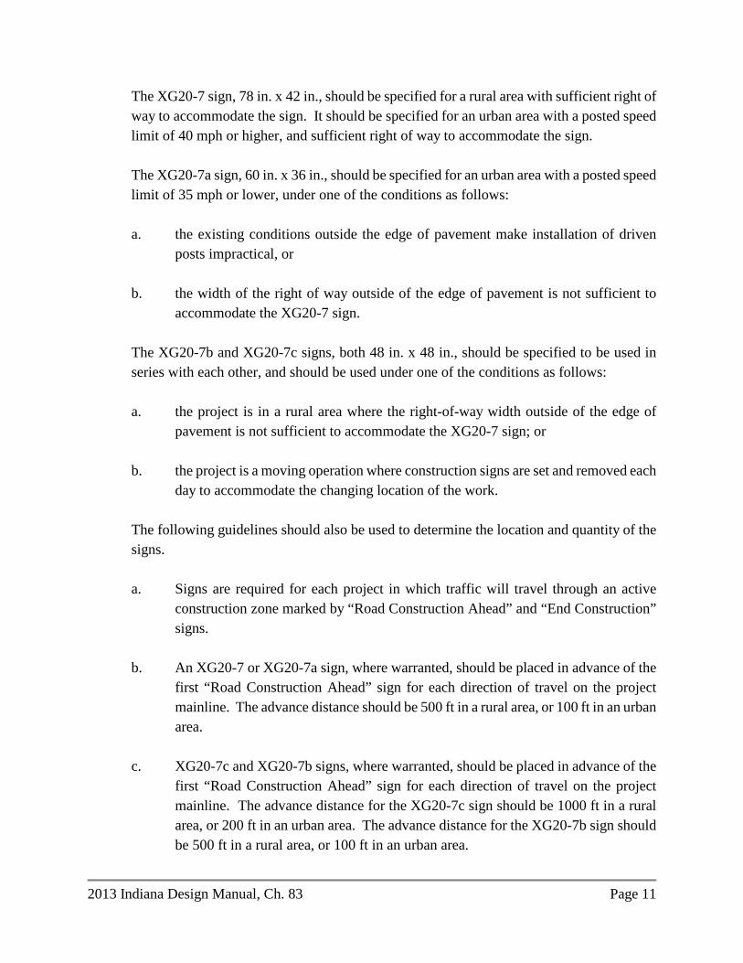
The XG20-7 sign, 78 in. x 42 in., should be specified for a rural area with sufficient right of way to accommodate the sign. It should be specified for an urban area with a posted speed limit of 40 mph or higher, and sufficient right of way to accommodate the sign.
The XG20-7a sign, 60 in. x 36 in., should be specified for an urban area with a posted speed limit of 35 mph or lower, under one of the conditions as follows:
a. the existing conditions outside the edge of pavement make installation of driven
posts impractical, or
b. the width of the right of way outside of the edge of pavement is not sufficient to accommodate the XG20-7 sign.
The XG20-7b and XG20-7c signs, both 48 in. x 48 in., should be specified to be used in series with each other, and should be used under one of the conditions as follows:
a. the project is in a rural area where the right-of-way width outside of the edge of
pavement is not sufficient to accommodate the XG20-7 sign; or
b. the project is a moving operation where construction signs are set and removed each day to accommodate the changing location of the work.
The following guidelines should also be used to determine the location and quantity of the signs.
a. Signs are required for each project in which traffic will travel through an active
construction zone marked by “Road Construction Ahead” and “End Construction” signs.
b. An XG20-7 or XG20-7a sign, where warranted, should be placed in advance of the
first “Road Construction Ahead” sign for each direction of travel on the project mainline. The advance distance should be 500 ft in a rural area, or 100 ft in an urban area.
c. XG20-7c and XG20-7b signs, where warranted, should be placed in advance of the
first “Road Construction Ahead” sign for each direction of travel on the project mainline. The advance distance for the XG20-7c sign should be 1000 ft in a rural area, or 200 ft in an urban area. The advance distance for the XG20-7b sign should be 500 ft in a rural area, or 100 ft in an urban area.

Page 12 2013 Indiana Design Manual, Ch. 83
d. Signs should not be placed on side roads or ramps leading into a construction zone.
e. Signs are not required if the active construction zone is completely isolated from live
traffic, i.e., a full road closure with a detour, or construction along a new alignment.
The location of each sign should be indicated as for other construction signs shown on the traffic-maintenance plan.
83-2.06 Portable Changeable Message Sign [Rev. May 2012] A portable changeable message sign (PCMS) is effective in communicating construction-zone information to the general public. Its use in a project shall be as outlined in the INDOT Guidelines for Portable Changeable Message Signs. The Guidelines appear on the Department website, at http://www.in.gov/dot/div/contracts/design/PCMS.pdf. 83-2.06(01) Need [Rev. May 2012] A PCMS should be considered for each project which includes the following: 1. intermittent or short term, road, lane, or ramp closure; 2. frequent changes in traffic patterns; 3. at least one road with traffic volume that will be at or over capacity during construction; or 4. other project as deemed necessary by the following:
a. the district office; b. the Construction Management Division; or c. the Traffic Management and District Support Business Unit.
A PCMS should not be used to convey a message that can be effectively conveyed with static signing. The need for a PCMS and the selection of messages should be considered during the course of Maintenance of Traffic (MOT) Plan development. In developing the MOT Plan, the designer should determine the answers to the questions as follows. 1. What type of closures or restrictions does the MOT Plan generate? 2. How long will the closures or restrictions be in effect? 3. Will potentially hazardous conditions exist, such as narrow lane widths, or workers,

2013 Indiana Design Manual, Ch. 83 Page 13
equipment, or materials encroaching onto the travel lanes? If so, for how long? 4. Is queuing or delay likely to occur as a result of the MOT Plan? 5. Will a work zone speed limit that is at least 15 mph lower than the permanent posted speed
be enacted? 6. What is the crash history of the project location? Conferring with the district Construction and Traffic offices will provide insights to these issues. With this information, the Guidelines can be applied to determine whether a PCMS should be included, and, if so, what messages should be displayed. 83-2.06(02) Design Considerations [Rev. May 2012] The MUTCD provides the design and application criteria relative to a PCMS. The designer should also consider the following in specifying a PCMS. 1. Display. The display should provide not more than the maximum amount of information that
can be read and comprehended by the motorist at a quick glance, i.e., no rolling messages. A PCMS is capable of displaying three lines of eight characters each. There should be not more than two messages phased in order to provide readability and comprehension. Each message should be able to stand alone. For more than two messages, two signs should be used.
2. Location. The sign should be visible from 2500 ft under ideal day and night conditions. The
first message should be legible at a minimum distance of 650 ft from each lane. A PCMS is typically placed in advance of other advance warning signs. For more information on location see the Guidelines, Placement section.
3. Traffic-Control Devices. A PCMS may be used as a supplement, but it should not be used as
a substitute to the proper use of other traffic control devices. 4. Flashing-Arrow Sign. A PCMS should not be used as an alternative to a flashing-arrow sign.
However, a PCMS may be used to simulate an arrow display in the message. 83-2.06(03) Plans Requirements [Added May 2012] If a PCMS is required, the following information will be shown on the plans.

Page 14 2013 Indiana Design Manual, Ch. 83
1. Approximate Location. Unless there are specific reasons otherwise, each PCMS is to be located as shown in the Guidelines, Tables 1 and 2.
2. Message Content. Each message shall be selected from the standard messages shown in the
Guidelines, Table 7, or developed as non-standard, as described in the Guidelines, Section V. The district Traffic Office or the Traffic Management Center can be consulted for assistance with message development.
Figure 83-2E, Programming Information for Portable Changeable Message Sign, on the editable-documents website, http://www.in.gov/dot/div/contracts/design/dmforms/ index.html, shall be completed and included in the Contract Information book for each non-standard message on each PCMS.
83-2.06(04) TMC Control of PCMS Operation [Added May 2012] As part of the Traffic Management Plan for a project in an Advanced Traffic Management System (ATMS) area, the designer shall consult with the district Construction Office and the appropriate Traffic Management Center (TMC) to determine whether TMC control of the PCMS is desired. The ATMS areas are as follows. 1. Indianapolis and Southern Indiana, Indianapolis TMC
I-64, mile 118 to 124 I-65, mile 0 to 9 I-65, mile 86 to 149 I-69, mile 0 to 29 I-70, mile 55 to 106 I-74, mile 66 to 73 I-74, mile 94 to 101 I-265, mile 0 to 9 I-465, mile 0 to mile 53 I-865, mile 0 to mile 5
2. Northwest Indiana, Gary TMC
I-65, mile 236 to 262 I-80/94, mile 0 to 16 I-94, mile 16 to 46 SR 912, mile 6 to 10
If the PCMS will be TMC controlled, a unique provision for the Aries Field Processor should be included in the contract. This unique provision should be obtained from the ITS Technology

2013 Indiana Design Manual, Ch. 83 Page 15
Deployment Office upon agreement that the TMC will control messaging. 83-2.07 Flashing-Arrow Sign A flashing-arrow sign is used to supplement other traffic-control devices. It is used where additional warning and directional information is required to assist in merging and controlling traffic through or around the work activity. A flashing-arrow sign should be used on each freeway construction project requiring a lane closure. For another site, the designer will determine the need for a flashing-arrow sign on a project-by-project basis. The applications where a flashing-arrow sign may be considered are as follows: 1. work in vicinity of an entrance or exit ramp; 2. median crossover on a freeway; 3. interior or double-lane closure on a freeway or other roadway of 4 or more lanes; 4. right-lane closure on the far side of an intersection; or 5. mobile operation on a shoulder or roadway of 4 or more lanes. The INDOT Standard Drawings, the INDOT Standard Specifications, and the MUTCD provide the Department’s criteria for the placement, design, and application of a flashing arrow sign. The MUTCD also includes application diagrams. The following provides the designer with supplemental information on the use of a flashing-arrow sign. 1. Display. The applicable display modes are as follows.
a. Flashing Arrow or Sequential Arrow. This is used for a left- or right-lane shift or diversion.
b. Flashing Double Arrow. This is used for an interior-lane closure where traffic is
permitted to either travel left or right around the work activity. 2. Use and Location. The flashing-arrow sign should be located at the beginning of a lane-
merge taper. For a stationary activity, locate the sign on the shoulder or in the closed lane behind a channeling or barricade device. For a mobile operation, locate a mounted sign at the rear of the activity upstream of the maintenance vehicles. Where used in the vicinity of a ramp, median crossover, or side-road intersection, the flashing-arrows sign placement should not confuse the motorist. Figure 83-2D provides the recommended usages and the minimum legibility distances under ideal day or night conditions.
3. Two-Lane, Two-Way Operation (TLTWO). A flashing-arrow sign should not be used to
shift traffic in a TLTWO.

Page 16 2013 Indiana Design Manual, Ch. 83
4. Shoulder or Roadside Activity. A flashing-arrow sign should only be used in the flashing
caution mode for a shoulder or roadside work activity. 5. Flagger. A flashing-arrow sign should not be used if a flagger is used for traffic control at
the work site. 6. Multiple-Lane Closure. The designer should consider using multiple flashing-arrow signs for
a multiple-lane closure. In this situation, a flashing-arrow sign should be located at the beginning of each lane-merge taper. The designer should not use a flashing-arrow sign to laterally shift multiple lanes of traffic.
7. Traffic-Control Devices. The flashing-arrow sign may be used as a supplemental traffic-
control device, but it should not be used as a substitute to the proper use of signs, pavement markings, or lighting in a construction zone. The flashing-arrow sign should not replace other required signing.
83-3.0 CHANNELIZATION DEVICES The INDOT Standard Drawings, the INDOT Standard Specifications, and the MUTCD provide the Department’s criteria for the selection, application, and placement of channelization devices. The MUTCD also includes application diagrams for the use of these devices. 83-3.01 Types There are a number of channelization devices available, each having its specific application in a construction operation (e.g., crossover, runaround, lane closure, road closure, or 2-lane, two-way operation). The following channelization devices are used in a construction zone. 1. Barricade.
a. Type I or Type II Barricade. INDOT does not use this type of barricade.
b. Type III Barricade. This is used to close a roadway. Section 83-3.04 provides the guidelines for its application and placement.
2. Drums. Drums are used in a linear series to channelize and delineate the desired travel path.
They may also be used individually or a group to mark a specific location. They are used for

2013 Indiana Design Manual, Ch. 83 Page 17
channelization and can be easily shifted to accommodate changing conditions within the construction zone. However, for a temporary lane closure during daylight hours, cones, tubular markers, or vertical panels may be used in lieu of drums.
3. Cones. Traffic cones are channelization devices used to delineate a travel path, divide
opposing traffic lanes, divide traffic lanes in the same direction, or delineate a short-duration construction, maintenance, or utility activity.
4. Tubular Markers or Vertical Panels. These devices are used to channel traffic, divide
opposing lanes of traffic, or divide travel lanes in place of drums where space is limited. Tubular markers and vertical panels have less visible area than other devices and should be used only where space restrictions do not allow for use of more-visible devices. These devices are to be used a divided non-freeway.
5. Temporary Asphalt Divider. This device should not be used for separating traffic. 6. Temporary Concrete Barrier (TCB). TCB should only be used where positive protection is
desired, and not based on channelization needs. This device should be used on a freeway. The TCB should be located behind and in conjunction with supporting channelization devices, delineators, or pavement markings. Section 82-4.03 provides information on the application and placement of the TCB. Delineators and steady-burning lamps should also be attached to the TCB. However, where used between lanes in a 2-lane, two-way operation, experience has shown that opposing vehicular headlights wash out the lamp and cannot be safely maintained. Therefore, lamps should not be used in this situation.
7. Delineators. Delineators provide retro-reflection from headlights and are supplemental
devices used to indicate the roadway alignment and the intended path through the construction zone. Delineators are used along the pavement edge in a runaround operation and are attached to the TCB.
8. Longitudinal Pavement Markings. The application of pavement markings is provided in
Section 83-4.0. Longitudinal pavement markings should only be used in combination with other primary channelization devices to delineate the desired travel path. A temporary double solid yellow line should be used in conjunction with tubular markers or vertical panels or TCB. Markings should also be used on each undivided roadway of 4 or more lanes. Revisions to existing pavement markings are not required for a temporary daylight lane closure.
Channelization devices are used in a construction zone to warn the motorist of work activities in or near the traveled way, to protect workers in the area, and to guide the motorist or pedestrian safely

Page 18 2013 Indiana Design Manual, Ch. 83
through and around the work site. Because each construction project differs, the selection, application, and location of these devices should be determined on a project-by-project basis.

2013 Indiana Design Manual, Ch. 83 Page 19
83-3.02 Taper Length The required length of tapered section delineated by channelization devices is shown on the INDOT Standard Drawings. Figures 83-3B and 83-3C provide the minimum taper requirement for each taper application in a construction zone (e.g., lane closure, lane shift). 83-3.03 Spacing As with a transition taper, the longitudinal spacing of channelization devices is dependent on vehicular speed. In a 1-lane, two-way traffic operation, the spacing at a tapered section should be 10 ft for a 50-ft taper length, or 20 ft for a 100-ft taper length. A device spacing of 20 ft should be used for an Interstate-route taper. Tubular markers should be at 50-ft spacing. Figure 83-3D provides suggested spacing of channelization devices for other conditions. Unless otherwise specified, the maximum spacing of drums, cones, or vertical panels should be based on Figure 83-3D. 83-3.04 Type III Barricade The Department uses a type III-A or type III-B barricade for a road closure. The Type III-A barricade is used where traffic is not allowed behind the barricade. Reflectorized rails are used only on the side facing traffic. The Type III-B barricade is used where traffic is allowed behind the barricade. Reflectorized rails are required on both sides of the barricade. The designer should also consider the following. 1. Materials. A type III barricade is constructed with three 12-ft sections mounted on skid-type
supports or on posts driven into the ground. Use a skid-mounted barricade where the barricade is to be located on the traveled way or shoulder. Use a post-driven barricade where the barricade is to be outside of the paved portion of the roadway.
2. Complete Closure. A type III-A barricade should extend completely across the roadway and
across a roadway side slope that is 3:1 or flatter within the right of way. During non-working hours, openings are not allowed within the barrier assembly.
3. Divided Highway. Where one set of lanes of a divided facility is closed to traffic, a type
III-A barricade will be required across the pavement area and on slopes which are 3:1 or flatter from the right-of-way line to the centerline of the median. An additional barricade will be required across the closed portion where the facility intersects with a local road (e.g., county road, drive). An additional barricade will be required where a bridge or pipe is to be removed; see Item 6.

Page 20 2013 Indiana Design Manual, Ch. 83
4. Crossover. Specify a type III-B barricade where a crossover on a divided facility is required
because one set of lanes is closed for construction and two-way traffic is being maintained on the other set.
5. Local Traffic. If local traffic is allowed to use the facility under construction, use a type III-
B barricade at the beginning and end portions of the closed road. Each barricade should extend onto side slopes of 3:1 or flatter, within the highway right-of-way. An additional barricade will be required where a bridge or pipe is to be removed, see Item 6.
6. Bridge or Pipe Removal. Where there is a possibility that a vehicle could be on a closed
facility and where there is a bridge removal, pipe removal, or other hazard location, provide an additional type III barricade within 150 ft of the hazard.
7. Road-Closure-Sign Assembly. Where a type III barricade is used, the designer is required to
show a road-closure-sign assembly on the plans. However, do not use such a sign assembly next to a lane closure where adjacent lanes remain open to traffic, or where a barricade is specified for closure of a lane on an undivided facility of 4 or more lanes where the remaining lanes are being used to maintain traffic.
83-4.0 PAVEMENT MARKINGS The INDOT Standard Drawings and the MUTCD provide the Department’s criteria for the selection, application, and placement of pavement markings in a construction zone. The INDOT Standard Specifications provides additional information on temporary-pavement-marking material usage. The following provides supplemental guidelines to these sources. 83-4.01 Types 83-4.01(01) Paint Quick-drying traffic paint is a low-cost, temporary pavement marking. To improve reflectivity, glass beads are required. Temporary paint is a non-removable type of temporary pavement marking. The Department does not desire the use of temporary paint markings on a final pavement surface. However, temporary paint may be the most suitable choice under certain conditions, particularly if temporary markings are anticipated to be in place through the winter months.

2013 Indiana Design Manual, Ch. 83 Page 21
83-4.01(02) Temporary Raised Pavement Markers In a high-traffic-volume location, raised temporary pavement markers should be considered as a supplemental device to improve delineation through the construction zone. Typical locations include canter line, lane line, gore area, or where there are changes in the alignment (e.g., lane closure, lane shift). For a center line or lane line, temporary raised pavement markers are placed at the midpoint in the each gap, i.e., every 40 ft. For a taper, gore, etc., the raised markers should be spaced at 20 ft. Temporary raised pavement markers must be removed prior to the placing of the next pavement course. 83-4.01(03) Temporary Pavement-Marking Tape Temporary pavement-marking tape is an excellent material choice where there is a change to the traffic pattern during construction (e.g., crossover switch). Temporary tape can be easily and quickly installed and, if necessary, easily removed. Disadvantages of temporary tape are that it tends to move or break up under heavy traffic volume, and that it is not suitable for usage during the winter months. Temporary pavement-marking tape requires significant maintenance in comparison to temporary paint. The following describes the temporary pavement-marking tapes used by the Department. 1. Type I. Type I tape may be used as a temporary center line, lane line, or no-passing-zone line
that is placed parallel to the normal pavement marking pattern, or as a temporary transverse marking or pavement-message marking. It should also be used where pavement markings are placed at an angle to the normal pavement-marking pattern (e.g., taper for lane closure, lane shift). Type I tape is a removable type of temporary pavement marking.
2. Type II. Type II tape is used on a pavement which is expected to be removed or covered by
additional pavement courses. It may be used as a center line, lane line, or edge line that is parallel to the normal pavement markings. It also may be used as a center line or lane line on a resurfacing overlay course. Type II tape is a non-removable type of temporary pavement marking.
83-4.01(04) Thermoplastic or Epoxy Markings Thermoplastic or epoxy markings are used in a construction zone only if the traffic volume is high, and the temporary traffic pattern will be in place for over one year. Thermoplastic or epoxy markings are non-removable types of pavement markings.

Page 22 2013 Indiana Design Manual, Ch. 83
83-4.01(05) Buzz Strips Buzz strips are used on a high-speed facility of 4 lanes or more in advance of a lane closure, alignment change, or stop condition to warn the motorist of the impending change. They are made with extruded material or repeated passes of pavement-marking tape to reach a ¼-in. height. Figure 83-4A illustrates the typical layout for buzz strips with a lane closure. The spacing criteria are also applicable to the other conditions listed above. 83-4.02 Application The application of temporary pavement markings in a construction zone depends on facility type, project duration, project length, and anticipated traffic volume. The phasing of temporary traffic control during construction should be considered. The temporary pavement markings should be selected that are best suited to the anticipated conditions and are most economical for the project. The removal of a removable temporary pavement marking is included in the removable-temporary-pavement-marking quantity. If non-removable markings that must be removed are selected as part of the planned traffic-maintenance plan, a quantity for removal of the non-removable markings is required. If non-removable temporary pavement markings are necessary on a final surface, placement of the temporary markings should be indicated to be as near as possible to the location of the final permanent pavement markings. 83-5.0 TEMPORARY TRAFFIC SIGNAL [Rev. Mar. 2016] 83-5.01 Location The use of a temporary traffic signal in a construction zone will be determined on a project-by-project basis. The warrant criteria for permanent installations in Section 502-3.02 should be used to help determine if a temporary traffic signal is warranted. However, the traffic volume expected during construction should be used for the warrant analysis. An Official Action, as described in Section 83-1.03, must be coordinated through the district traffic engineer. Locations where a temporary signal installation may be used include the following: 1. intersection where an existing signal must be maintained; 2. existing non-signalized intersection or drive where construction patterns and traffic volume
now warrant a signal;

2013 Indiana Design Manual, Ch. 83 Page 23
3. temporary haul road or other temporary access point; 4. long-term one lane, two-way traffic operation (e.g., bridge lane closure); or 5. crossroad or ramp intersection where there is an increase in traffic or there is a decrease in
capacity due to the construction. 83-5.02 Application [Rev. Mar. 2016] The designer should consider the following. 1. Existing Signals. The designer should determine the impacts that a construction activity
has on existing signal operations and should attempt to maximize the level-of-service. For example, the designer should consider the following:
a. recommend re-timing or re-phasing the signal to compensate for changes in traffic
volume, mix, or patterns, and for changes in lane designation or intersection-approach geometrics; and
b. physically relocating poles or adjusting signal heads to maintain compliance with
the IMUTCD. c. if temporary signals will be used, the designer should develop the signal timing
plan and show placement locations on the plans.
Section 502-3.0 and the IMUTCD provide design information for a traffic signal.
2. Bridge. If a lane is expected to be closed overnight, a temporary signal should be considered.
3. Type of Temporary Signal – One Lane, Two-Way Traffic Control. A temporary traffic
signal may either be fixed or portable, the type selected should be detailed on the plans and the appropriate pay item included in the cost estimate.
a. If a temporary traffic signal is chosen as an element of a temporary traffic control
plan the designer should consider whether it may be more cost effective to use a portable signal. Portable signals are mounted on trailers rather than wood poles and are generally rented by the contractor. When the need for a temporary traffic signal is expected to be less than six weeks, or the cost to bring electric service to

Page 24 2013 Indiana Design Manual, Ch. 83
the location is more than $10,000, portable traffic signals will typically be less expensive. Portable signals require a relatively flat area, approximately 8 ft by 8 ft in size, to accommodate the trailer. If necessary, a temporary landing area for the trailer may be constructed, using suitable material, on the side slope. If a temporary landing area is needed it should be shown on the plans.
b. In order to include the portable signal pay item into a contract the designer must
obtain concurrence from the district Traffic Office that the portable type is the best option. The Temporary Traffic Signal Type Determination form is available from the Department’s Editable Documents webpage, under Traffic Maintenance. The form should be submitted to the district Traffic Engineer as early as possible in the plan development process but at least prior to Stage 1 plan submittal.
4. Type of Temporary Signal - Intersection Traffic Control. In accordance with the
IMUTCD, Section 4D.32 temporary signals for intersection traffic control must be fixed. However, roads and drives within a one lane, two-way work zone may be controlled by portable signals.
5. Vehicle Detection. Whether fixed temporary or portable, the signal should include
vehicle detection. The detection area should be shown on the plans. See Figure 83-5A, Vehicle Detection Typical Placement Areas. The Standard Specifications allow the contractor to use either inductive loop or wireless detection for fixed temporary signals, but only wireless for portable. Where it is determined that another type of detection is needed, a unique special provision should be included in the contract.
6. Phasing/Timing Plans for Portable Signals. If portable signals will be used, the designer should develop the signal phasing and timing plan in accordance with the FHWA Signal Timing Manual and complete the Temporary Signal Timing Plan (RSP 801-T-212) and include this in the contract documents. a. For consultant designs the consultant shall be prequalified in Category 10.1,
Traffic Signal Design. b. For in-house projects the designer should discuss the phasing and timing plan with
district Traffic Engineer or the Systems Engineer in the Traffic Management Division.
c. Total cycle length should be limited to 255 seconds and the all red clearance
interval to 99 seconds. The following parameters may be used:

2013 Indiana Design Manual, Ch. 83 Page 25
i. Actuation should be provided and shown on the plans. See Figure 83-5A, Vehicle Detection Typical Placement Areas.
ii. The minimum green time for both phases is based on driver expectation and may be set at 15 seconds for major arterials regardless of speed and 10 seconds for minor arterials or collectors. The Signal Timing Manual allows for lower values based on engineering judgment (see Table 5-3).
iii. The maximum green time for each phase should be exceed the time it takes to clear a peak hour queue but should be limited to no more than 90 seconds for arterials and 40 seconds for collectors. This queue clearance time can be estimated by this equation: Gq = 3 + 2n where, Gq = green time to clear queue n = the number of vehicles in the queue To determine the number of vehicles in queue, the peak hour volume is divided by the number of cycles per hour so establishing Gq is an iterative process.
iv. Yellow change interval should be based on the approach speed. Yellow
change intervals on rural state highways may be set at 4 seconds for 40 mph and 5 seconds for 45 mph or greater.
v. All red clearance phase must be established by calculating the travel time
from signal to signal, which is the distance from signal to signal divided by the operating speed.
T = d ÷ avg. operating speed where, T = travel time for red clearance (seconds);
d = distance between signals (ft) avg. operating speed (ft/sec) = 1.467 x avg. operating speed (mph) The average operating speed through the work zone will depend on many conditions, e.g. truck volume, length of the work zone, lane width, shoulder width, offset to barriers, and pavement condition, but can be estimated at 25 mph.

Page 26 2013 Indiana Design Manual, Ch. 83
d. The designer should confirm that the anticipated queue will not encroach upon adjacent intersections. If encroachment is expected additional planning will be needed, e.g. the portable signal may need coordinated with the adjacent signal.
7. Plan Sheets. Show each temporary-signal installation, whether fixed or portable, in the traffic-maintenance plan. The placement locations for temporary signals should conform to the IMUTCD requirements for lateral and longitudinal signal positioning. For portable signals the designer should indicate if both signal heads must be mounted overhead.
8. Pay Items. A supplemental description noting the location, by intersection or route
number and reference post for one lane, two-way operations, must be included with the use of the fixed temporary signal or portable signal pay item. Vehicle detection is included in the cost of the pay item.
83-6.0 HIGHWAY LIGHTING 83-6.01 Types The lighting devices that are used in a construction zone are as follows: 1. hazard-identification beacons (flashing warning lights); 2. steady-burning warning lamps; 3. warning lights; 4. floodlights; and 5. conventional highway lighting. 83-6.02 Warrants Hazard-identification beacons, steady-burning electric lamps, and warning lights are used to supplement signs, barriers, or channelization devices, and emphasize specific signs, hazard areas, and the desired travel path. The warrants for lighting devices should satisfy the MUTCD. Floodlights are used to illuminate the work area during a nighttime operation (e.g., flagger station, equipment crossing, area requiring supplemental lighting). For conventional highway lighting, the need for temporary lighting will be determined on a project-by-project basis. Existing highway illumination should be maintained unless discontinuance of the highway illumination is specifically permitted. The warrants provided in Section 502-4.02 for permanent highway lighting should be reviewed to assist in determining the need for temporary

2013 Indiana Design Manual, Ch. 83 Page 27
lighting. The designer should consider the use of temporary lighting with the characteristics as follows: 1. high traffic volume; 2 high traffic speed; 3. heavy queuing or congestion; 4. area with complicated traffic maneuvers (e.g., freeway crossover, intersection); and 5. other area where a hazardous location may exist. If existing light standards are removed or if bulbs are shut off during construction, the designer should consider providing temporary lighting until permanent lighting is reinstalled. In a construction zone, the Department uses high-pressure sodium lamps mounted on temporary wood posts. However, the designer may consider portable lighting as an option. Section 502-4.0 provides additional information on the design of highway lighting.

English-Units
Value Metric-Units Equivalent
SPEED LIMIT 30 50
35 or 40 60 45 70 50 80 55 90
60 or 65 100 70 110
LONGITUDINAL DISTANCE 500 ft 150 m 1000 ft 300 m 1500 ft 450 m ¼ mi 400 m ½ mi 800 m 1 mi 1.5 km 2 mi 3 km
ENGLISH-TO-METRIC UNITS CONVERSION
Figure 83-2A

Existing Facility and Construction Type
Existing Posted Speed 50 mph 55 mph 65 mph
4-lane Interstate with crossover to a 2-lane
facility n/a
WZ 45 mph with TCB
WS 45 mph
WZ 55 mph with TCB
WS 45 mph
4-lane Interstate with lane closure without
a crossover n/a WS 45 mph
WZ 55 mph
WS 45 mph 6-lane Interstate with crossover to a 4-lane
facility with TCB WS 40 mph WS 45 mph
WZ 55 mph
WS 45 mph 6-lane Interstate with lane closure without
a crossover WS 40 mph WS 45 mph
WZ 55 mph
WS 45 mph
Non-Interstate divided highway with
crossover Project-by-project
WZ 45 mph with TTM & TDSYL
WS 45 mph
WZ 55 mph with TCB or TTM &
TDSYL. WS 45 mph
Non-Interstate divided highway with lane closure without
a crossover Project-by-project WS 45 mph
WZ 55 mph
WS 45 mph
Where:
WS = Work-Site Speed Limit (Indiana Statutes) WZ = Work-Zone Speed Limit (Official Action) TCB = Temporary Concrete Barrier n/a = Not Applicable TTM = Temporary Tubular Markers TDSYL = Temporary Double Solid Yellow Line
Note: Speed limit may vary based on circumstances and actual field conditions.
SUGGESTED DIVIDED-HIGHWAY SPEED LIMIT IN WORK ZONE OR WORK SITE
Figure 83-2B


Panel Type 1 Permitted Use Minimum Legibility
Distance 2
A Permitted on facility with speed lower than 35 mph. Appropriate for use on low-speed urban facility.
2600 ft
B Appropriate for intermediate-speed facility, or for maintenance or mobile operation on high-speed roadway. Not used by INDOT.
4000 ft
C Permitted on every facility. Appropriate for use on a high-speed, high-volume traffic-control project.
5200 ft
Notes: 1. For panel type, see the INDOT Standard Specifications and Federal MUTCD Part VI. 2. Minimum legibility distance under ideal day or night conditions.
SUGGESTED USE AND LOCATION OF FLASHING-ARROW SIGN
Figure 83-2D

LOCATION OF PCMS: MESSAGE TO BE DISPLAYED DURING MOT PHASE, EVENT, ETC.: CREATED BY: MESSAGE, PHASE 1
MESSAGE, PHASE 2
PROGRAMMING INFORMATION FOR PORTABLE CHANGEABLE MESSAGE SIGN
Figure 83-2E

Taper Type Minimum Length
Upstream
Merging L Shifting 3 ½ L Shoulder 1/3 L Two-Way Traffic 100 ft
Downstream (optional) 100 ft per Lane Notes: 1. See the INDOT Standard Drawings for L. 2. Figure 83-3C illustrates the permissible taper types. 3. May be used for determining buffer-zone length.
TAPER-LENGTH CRITERIA FOR CONSTRUCTION ZONE
Figure 83-3B


Construction-Zone
Design Speed (mph)
Suggested Maximum Spacing (ft) Tapered Section
Tangent Section
25 * 20 * 40 30 30 60 35 35 70 40 40 80 45 45 90 50 50 100 55 55 110 60 60 120
* For a speed of 25 mph or lower, spacing should not be less than 20 ft.
SUGGESTED MAXIMUM SPACING OF CHANNELIZATION DEVICES
Figure 83-3D