Embed Size (px)
Citation preview

INDIANA DEPARTMENT OF TRANSPORTATION—2013 DESIGN MANUAL
PART 5
Traffic and Safety
NOTE: Revisions to these chapters occurring after January 1, 2013 appear in this manual. Users should consult Design Memoranda listed below and on the title sheet of each affected chapter for details related to revisions.
Design
Memorandum Revision
Date Sections Affected
13-01 Jan. 2013 Figure 82-6B, Figure 82-6C 13-03 Feb. 2013 82-6.03 13-06 Mar. 2013 77-5.05 13-07 Mar. 2013 77-4.05 13-12 June 2013 78-3.04, 78-5.0, 78-6.0, 78-7.0, Figure 78-5B, Figure 78-5C 13-13 July 2013 76-3.02(05), 76-3.02(06), 76-3.02(07) 14-01 Feb. 2014 Ch. 75, 76, 77, 78 superseded by Ch. 502 15-19 Sept. 2015 502-2.01(03), Figure 502-2C 16-02 Jan. 2016 Sections 502-4.01 thru 502-4.07 16-03 Jan. 2016 502-3.03(02), 502-3.03(05), and 502-3.04(05) - Editorial 16-06 Mar. 2016 Section 83-5.0, Figure 83-5A 16-36 Nov. 2016 502-3.03(05), item 4 17-09 May 2017 502-1.01(05)
INDIANA DEPARTMENT OF TRANSPORTATION—2013 DESIGN MANUAL
CHAPTER 502
Traffic Design
Design
Memorandum Revision
Date Sections Affected
14-01 Feb. 2014 Ch. 75, 76, 77, 78 superseded by Ch. 502 15-19 Sept. 2015 502-2.01(03) 16-02 Jan. 2016 Sections 502-4.01 thru 502-4.07 16-03 Jan. 2016 502-3.03(02), 502-3.03(05), and 502-3.04(05) - Editorial 16-36 Nov. 2016 502-3.03(05), item 4 17-09 May 2017 502-1.01(05)

Page 2 2013 Indiana Design Manual, Ch. 502
TABLE OF CONTENTS
TABLE OF CONTENTS ................................................................................................................ 2
LIST OF FIGURES ........................................................................................................................ 8
502-1.0 ROADWAY SIGNING .................................................................................................. 11 502-1.01 General Criteria ........................................................................................................ 11
502-1.01(01) References ...................................................................................................... 11 502-1.01(02) Reflectorization .............................................................................................. 12 502-1.01(03) Illumination .................................................................................................... 13 502-1.01(04) Sign Placement ............................................................................................... 13 502-1.01(05) Ground-Mounted Sign Supports [Rev. May 2017] ........................................ 14 502-1.01(06) Overhead Sign ................................................................................................ 17 502-1.01(07) Sign Priority ................................................................................................... 18 502-1.01(08) Computer Software ........................................................................................ 18 502-1.01(09) Symbology ..................................................................................................... 19 502-1.01(10) Sign Structure Selection Guidance and Design Criteria ................................ 19 502-1.01(11) Design Criteria for Traffic Sign Structure ..................................................... 20 502-1.01(12) Design Criteria for Sign Structure Foundation .............................................. 22 502-1.01(13) Applications ................................................................................................... 22 502-1.01(14) Scoping Guidelines for 3R and 4R Projects................................................... 22
502-1.02 Regulatory Sign ........................................................................................................ 23 502-1.02(01) Official Action ............................................................................................... 23 502-1.02(02) “Stop” or “Yield” Sign ................................................................................... 25 502-1.02(03) Speed Limit Sign ............................................................................................ 25 502-1.02(04) “No U-Turn” Sign .......................................................................................... 26 502-1.02(05) Two-Way Left Turn Only (TWLTO) Sign .................................................... 26 502-1.02(06) “Do Not Pass” Sign ........................................................................................ 26 502-1.02(07) Parking Signs ................................................................................................. 27 502-1.02(08) “No Turn on Red” Sign .................................................................................. 27
502-1.03 Warning Signs .......................................................................................................... 27 502-1.03(01) Placement of Advance Warning Signs........................................................... 27 502-1.03(02) Advance Turn or Advance Curve Symbol Sign............................................. 27 502-1.03(03) Chevron Symbol Sign .................................................................................... 28 502-1.03(04) Signal Ahead Symbol Sign ............................................................................ 29 502-1.03(05) Advisory Exit Speed Sign .............................................................................. 29 502-1.03(06) “No Passing Zone” Sign ................................................................................. 29 502-1.03(07) Advance Street or Road Name Sign .............................................................. 29 502-1.03(08) Use of Fluorescent Yellow Sign Sheeting ..................................................... 29

2013 Indiana Design Manual, Ch. 502 Page 3
502-1.04 Guide Sign ................................................................................................................ 30 502-1.04(01) General Sign Design Requirements [Rev. May 2017] ................................... 30 502-1.04(02) Post-Interchange Sign Sequence .................................................................... 31 502-1.04(03) General Services Sign .................................................................................... 32 502-1.04(04) Logo Signing .................................................................................................. 32 502-1.04(06) Rest Area, Weigh Station, and Destination Signage ...................................... 33 502-1.04(07) Street Name Sign ........................................................................................... 33 502-1.04(08) Reference Markers, D10-1 thru D10-5 Series ............................................... 34 502-1.04(09) Railroad Grade Crossing Signing .................................................................. 35
502-1.05 Sign Plan Notes and Legend Items ........................................................................... 35
502-2.0 PAVEMENT MARKINGS ............................................................................................ 35 502-2.01 General ..................................................................................................................... 35
502-2.01(01) Functions and Limitations .............................................................................. 35 502-2.01(02) Standardization of Application ...................................................................... 36 502-2.01(03) Materials and Application [Rev. Sept. 2015] ................................................. 36 502-2.01(05) Coordination with Other IMUTCD Chapters ................................................. 38 502-2.01(06) References ...................................................................................................... 38 502-2.01(07) Official Action ............................................................................................... 38
502-2.02 Pavement and Curb Markings .................................................................................. 39 502-2.02(01) Yellow Center Line Pavement Markings and Warrants ................................ 39 502-2.02(02) No-Passing-Zone Pavement Markings and Warrants .................................... 40 502-2.02(03) No-Passing-Zone Record ............................................................................... 41 502-2.02(04) Other Yellow Longitudinal Pavement Markings ........................................... 42 502-2.02(05) White Lane Line Pavement Markings and Warrants ..................................... 43 502-2.02(06) Other White Longitudinal Pavement Markings ............................................. 43 502-2.02(07) Edge Line Pavement Markings ...................................................................... 44 502-2.02(08) Warrants for Use of Edge Lines ..................................................................... 45 502-2.02(09) Extension through Intersection or Interchange .............................................. 45 502-2.02(10) Lane Reduction Transition Markings ............................................................ 45 502-2.02(11) Approach Markings for Obstruction .............................................................. 45 502-2.02(12) Raised Pavement Markers (RPMs) ................................................................ 45 502-2.02(13) Raised Pavement Markers as Vehicle Positioning Guides with Other
Longitudinal Markings ................................................................................................ 46 502-2.02(14) Raised Pavement Markers Supplementing Other Markings .......................... 47 502-2.02(15) Raised Pavement Markers Substituting for Pavement Markings................... 47 502-2.02(16) Transverse Markings ...................................................................................... 47 502-2.02(17) Stop and Yield Lines ...................................................................................... 47 502-2.02(18) Do-Not-Block-Intersection Markings ............................................................ 48 502-2.02(19) Crosswalk Markings ...................................................................................... 48

Page 4 2013 Indiana Design Manual, Ch. 502
502-2.02(20) Parking-Space Markings ................................................................................ 49 502-2.02(21) Pavement Word and Symbol Markings ......................................................... 49 502-2.02(22) Speed Measurement Markings ....................................................................... 49 502-2.02(23) Speed Reduction Markings ............................................................................ 49 502-2.02(24) Curb Markings ............................................................................................... 49 502-2.02(25) Chevron and Diagonal Crosshatch Markings ................................................ 50 502-2.02(26) Speed-Hump Markings .................................................................................. 50 502-2.02(27) Advance Speed-Hump Markings ................................................................... 50
502-2.03 Markings for Roundabout Intersection ..................................................................... 50 502-2.04 Markings for Preferential Lane ................................................................................ 50 502-2.05 Markings for Toll-Road Plaza ................................................................................... 51 502-2.06 Delineators ................................................................................................................ 51
502-2.06(01) General ........................................................................................................... 51 502-2.06(02) Delineator Details .......................................................................................... 52 502-2.06(03) Delineator Application ................................................................................... 52 502-2.06(04) Delineator Placement and Spacing ................................................................ 53 502-2.06(05) Truck-Climbing Lane ..................................................................................... 54
502-2.07 Colored Pavements ................................................................................................... 54 502-2.08 Islands ....................................................................................................................... 54
502-2.08(01) General ........................................................................................................... 54 502-2.08(02) Island Object Markers .................................................................................... 54 502-2.08(03) Island Delineators .......................................................................................... 54
502-2.09 Milled Longitudinal Rumble Stripes ......................................................................... 55
502-3.0 TRAFFIC SIGNALS ...................................................................................................... 58 502-3.01 General ..................................................................................................................... 58
502-3.01(01) Official Action ............................................................................................... 58 502-3.01(02) Plans Development ........................................................................................ 59 502-3.01(03) Request for a New Signal............................................................................... 59 502-3.01(04) Responsibilities .............................................................................................. 59
502-3.02 Preliminary Signal Design Activities ....................................................................... 60 502-3.02(01) Signal Warrant ............................................................................................... 60 502-3.02(02) Additional Considerations for Traffic-Signal Installation ............................. 60
502-3.03 Traffic-Signal Equipment and Operations ................................................................ 60 502-3.03(01) Traffic-Signal Controller................................................................................ 61 502-3.03(02) Pedestrian Control [Rev. Jan. 2016] .............................................................. 63 502-3.03(03) Preemption ..................................................................................................... 63 502-3.03(04) Controller Cabinet .......................................................................................... 66 502-3.03(05) Detector [Rev. Jan. 2016, Nov. 2016] ........................................................... 67 502-3.03(06) Traffic Signal-Head Components .................................................................. 72

2013 Indiana Design Manual, Ch. 502 Page 5
502-3.03(07) Signal-Support Structure ................................................................................ 75 502-3.03(08) Signal Cantilever Structure Selection Guidance and Design Criteria............ 76
502-3.04 Traffic Signal Design ............................................................................................... 78 502-3.04(01) Design Criteria ............................................................................................... 78 502-3.04(02) Signal Displays .............................................................................................. 79 502-3.04(03) Visibility Requirements ................................................................................. 80 502-3.04(04) Placement of Signal Equipment ..................................................................... 80 502-3.04(05) Pedestrian Signal [Rev. Jan. 2016] ................................................................ 81 502-3.04(06) Signing and Pavement Markings ................................................................... 82 502-3.04(07) Electrical System ........................................................................................... 82 502-3.04(08) Phasing ........................................................................................................... 85 502-3.04(09) Pre-timed Traffic Signal Timing .................................................................... 91 502-3.04(10) Traffic-Actuated Signal Timing ..................................................................... 95 502-3.04(11) Count Loops ................................................................................................. 100 502-3.04(12) Preferred Counting Configurations .............................................................. 101 502-3.04(13) Computer Software ...................................................................................... 101 502-3.04(14) Maintenance Considerations ........................................................................ 103 502-3.04(15) Traffic-Signal Loop Tagging Table ............................................................. 103
502-3.05 Coordinated-Signal-System Design ....................................................................... 103 502-3.05(01) System-Timing Parameters .......................................................................... 104 502-3.05(02) System Types ............................................................................................... 104 502-3.05(03) Communications Techniques ....................................................................... 107
502-3.06 Flashing Beacon ..................................................................................................... 107 502-3.06(01) Intersection-Control Beacon ........................................................................ 107 502-3.06(02) Warning Beacon ........................................................................................... 108 502-3.06(03) Speed Limit Sign Beacon ............................................................................. 108 502-3.06(04) Stop Sign Beacon ......................................................................................... 108 502-3.06(05) General Flashing Beacon Design ................................................................. 108 502-3.06(06) Pedestrian Hybrid Beacon ............................................................................ 109
502-4.0 HIGHWAY LIGHTING............................................................................................... 109 502-4.01 General ................................................................................................................... 109
502-4.01(01) References .................................................................................................... 110 502-4.01(02) Definitions of Terms .................................................................................... 110 502-4.01(03) State and Local Responsibilities .................................................................. 112 502-4.01(04) Lighting Studies ........................................................................................... 115
502-4.02 Warrants ................................................................................................................. 115 502-4.02(01) Warrant Criteria for Freeways ..................................................................... 115 502-4.02(02) Warrant Criteria for Interchanges ................................................................ 116 502-4.02(03) Warrant Criteria for Non-Freeways [Rev. Jan 2016] ................................... 116

Page 6 2013 Indiana Design Manual, Ch. 502
502-4.02(04) Criteria for Highway-Sign Lighting ............................................................. 116 502-4.02(05) Criteria for Rest Area ................................................................................... 116 502-4.02(06) Criteria for Truck Weigh Station ................................................................. 118 502-4.02(07) Criteria for Bridge Structure ........................................................................ 118 502-4.02(08) Criteria for Tunnel or Underpass [Rev. Jan. 2016] ...................................... 118 502-4.02(09) Criteria for Roundabout [Rev. Jan. 2016] .................................................... 118 502-4.02(10) Criteria for Other Facilities .......................................................................... 119 502-4.02(11) Reduction or Removal of Lighting [Rev. Jan. 2016] ................................... 119 502-4.03(12) Alternative criteria for urban streets [Added Jan. 2016] ............................... 120 502-4.02(13) Transition Lighting [Added Jan. 2016] ......................................................... 120 502-4.02(14) Adaptive Lighting [Added Jan. 2016] .......................................................... 120
502-4.03 Lighting Equipment ................................................................................................ 121 502-4.03(01) Foundation ................................................................................................... 121 502-4.03(02) Light Standard or Pole ................................................................................. 121 502-4.03(03) Mast Arm ..................................................................................................... 125 502-4.03(04) Luminaire [Rev. Jan. 2016].......................................................................... 126 502-4.03(05) Other Equipment [Rev. Jan. 2016] .............................................................. 129
502-4.04 Lighting Methodologies ......................................................................................... 130 502-4.04(01) Illuminance................................................................................................... 130 502-4.04(02) Luminance .................................................................................................... 131 502-4.04(03) Small-Target Visibility (STV) ..................................................................... 132
502-4.05 Design Procedure [Rev. Jan. 2016] ........................................................................ 132 502-4.05(01) Computerized Design [Rev. Jan. 2016] ....................................................... 132 502-4.05(02) Design Process [Rev. Jan. 2016] .................................................................. 133
502-4.06 Conventional Lighting Design ............................................................................... 144 502-4.06(01) Roadway Classification ............................................................................... 145 502-4.06(02) Design Criteria [Rev. Jan. 2016] .................................................................. 146 502-4.06(03) Equipment Considerations [Rev. Jan. 2016] ................................................ 146 502-4.06(04) System Configuration .................................................................................. 151 502-4.06(05) Roadside-Safety Considerations .................................................................. 151 502-4.06(06) Other Considerations [Rev. Jan. 2016] ........................................................ 153 502-4.06(07) Voltage-Drop Determination ....................................................................... 154
502-4.07 High-Mast Lighting Design [Rev. Jan. 2016] ........................................................ 155
502-5.0 INTELLIGENT TRANSPORTATION SYSTEM (ITS) ............................................. 157 502-5.01 General ................................................................................................................... 157
502-5.01(01) Purpose of ITS ............................................................................................. 158 502-5.01(02) National And Regional Architecture ........................................................... 158 502-5.01(03) Coordination with Traffic Management Centers ......................................... 159
502-5.02 Use of the ITS Strategic Deployment Plan ............................................................. 160

2013 Indiana Design Manual, Ch. 502 Page 7
502-5.03 Design Criteria ........................................................................................................ 161 502-5.03(01) ITS Infrastructure Component Locations .................................................... 161 502-5.03(02) Electrical Service Points .............................................................................. 161 502-5.03(03) ITS Cabinet .................................................................................................. 162 502-5.03(04) Support Structure ......................................................................................... 163
502-5.04 Devices ................................................................................................................... 164 502-5.04(01) Overhead Dynamic Message Signs (DMS) ................................................. 165 502-5.04(02) Travel Time Sign (TTS) ............................................................................... 166 502-5.04(03) Closed Circuit TV (CCTV) Camera System ............................................... 166 502-5.04(04) Detection ...................................................................................................... 168 502-5.04(05) Field Controller ............................................................................................ 170 502-5.04(06) Communication ............................................................................................ 170 502-5.04(07) ITS Handhole and Conduit .......................................................................... 172 502-5.04(08) Closed Circuit TV Site Requirements .......................................................... 173 502-5.04(09) Traffic Monitoring System........................................................................... 173
502-5.05 Plan Development Procedure ................................................................................. 177 502-5.05(01) Site Reviews ................................................................................................. 177 502-5.05(02) Bucket Truck Survey ................................................................................... 178
FIGURES .................................................................................................................................... 180

Page 8 2013 Indiana Design Manual, Ch. 502
LIST OF FIGURES 502-1A Luminaire Placement Dimensions for Overhead Signs 502-1B Sign Gore Treatment 502-1C(1) Sign Box Truss Structure Selection Guidance 502-1C(2) Sign Cantilever Structure Selection Guidance 502-1D Ball-Bank Indicator Readings 502-1E Sign Software Input and Spacing Requirements 502-1F Arrow Dimensions 502-1G Diamond Interchange Signing, Divided Highway over Freeway 502-1H Diamond Interchange Signing, Divided Highway over Freeway 502-1 I Diamond Interchange Signing, Undivided Highway over Freeway 502-1J Diamond Interchange Signing, Undivided Highway under Freeway 502-1K Full Cloverleaf Interchange Signing, Divided Highway over Freeway 502-1L Full Cloverleaf Interchange Signing, Divided Highway under Freeway 502-1M Full Cloverleaf Interchange Signing, Undivided Highway over Freeway 502-1N Full Cloverleaf Interchange Signing, Undivided Highway under Freeway 502-1 O Partial Cloverleaf Interchange Signing, Divided Highway over Freeway 502-1P Partial Cloverleaf Interchange Signing, Divided Highway over Freeway 502-1Q Partial Cloverleaf Interchange Signing, Divided Highway under Freeway 502-1R Partial Cloverleaf Interchange Signing, Divided Highway under Freeway 502-1S Partial Cloverleaf Interchange Signing, Undivided Highway over Freeway 502-1T Partial Cloverleaf Interchange Signing, Undivided Highway over Freeway 502-1U Partial Cloverleaf Interchange Signing, Undivided Highway under Freeway 502-1V Partial Cloverleaf Interchange Signing, Undivided Highway under Freeway 502-1W Trumpet Interchange Signing, System Interchange 502-1X Route Marker Assembly Post Details 502-1Y Post-Interchange Sequence Signs 502-1Z National and Regional Control Cities for Interstate and Major U.S. Routes 502-1AA General Service Signs and Supplemental Guide Sign Placement 502-1BB Reference Marker/Enhanced Reference Marker Locations 502-1CC Sign Plans Notes 502-1DD Sign Plan Legend 502-2A Typical Intersection Pavement Markings 502-2B Pavement Marking Lines Applications 502-2C Recommended Pavement-Marking Applications 502-2D Locations of Edge and Center Lines with Unpaved Shoulders 502-2E No-Passing-Zone Distances 502-2F No-Passing-Zone Distance Applications 502-2G Two-Way Left-Turn Lane Markings

2013 Indiana Design Manual, Ch. 502 Page 9
502-2H Two-Way Left-Turn Transition Markings, TWLTL to Exclusive Left-Turn Lane 502-2 I Exit Gore Markings 502-2J Longitudinal Taper Rate and Length 502-2K Delineator Application, Placement, and Spacing 502-2L Transition Markings, 4-Lane Undivided to 2-Lane Undivided 502-2M Transition Markings, 4-Lane Divided to 2-Lane Undivided 502-2N Transition Markings, 4-Lane Divided to 2-Lane Undivided 502-2 O Traffic Control Word/Symbol Markings 502-2P Truck-Climbing Lane Markings 502-2Q Channelized Island Markings, Triangular Island 502-2R Channelized Island Markings, Flush or Raised Corrugated Elongated Island 502-3A Typical Wireless Vehicle-Detection System 502-3B Typical Hybrid Wireless Vehicle-Detection System 502-3C Cable-Span Mounted Signal, Partial Bridle Configuration 502-3D Combination Signal-Luminaire Pole 502-3E Signal Head Placement, Rural Two-Lane Road with Obstructed Sight Distance 502-3F Signal Head Placement, Offsetting Intersection 502-3G Signal Head Placement, Rural Two-Lane Road with Truck Blocking View of Signal Heads 502-3H Signal Head Placement, Approaching Lanes with Permissible Phase and Parking on Near Side 502-3 I Signal Head Placement, Approaching Lanes with Left-Turn Lane with Permissible Phase and Parking on Far Side 502-3J Signal Head Placement, Approaching Lanes with Left-Turn Lane with Protected Phase 502-3K Signal Head Placement, Approaching Lanes with Left-Turn Lane with Permissible Phase 502-3L Signal Head Placement, Approaching Lanes with Left-Turn Lane with Protected/Permissible Phase 502-3M Signal Head Placement, Multi-Lane Roadway Approaching Lanes with Left-Turn Lane Protected Phase 502-3N Signal Head Placement, Approaching Lanes with Two Left-Turn Lanes with Protected Phase 502-3 O Signal Head Placement, Approaching Lanes with Right-Turn Overlaps 502-3P Sequence of Phases, Eight-Phase Dual-Ring Controller 502-3Q T-Intersection Three-Phase Operation 502-3R T-Intersection Four-Phase Operation, Multi-Lanes Approaches 502-3S Typical Intersection Four-Phase Operation 502-3T Four-Phase Operation, Separate Split Phases for Major Street 502-3U Four-Phase Operation, Separate Split Phase for Minor Street 502-3V Five-Phase Operation, Exclusive Pedestrian Phase

Page 10 2013 Indiana Design Manual, Ch. 502
502-3W Six-Phase Operation, Separate Left-Turn Phase for Major Street 502-3X Eight-Phase Operation, Dual Ring 502-3Y Typical Vehicle Movement and Phase Numbering 502-3Z Comparison of Left-Turn Phase Alternatives 502-3AA Detection Setback Distance 502-3BB Counting Loop Selection 502-3CC Counting Loop Selection, Frontage Roads and Parking Lots 502-3DD Counting Loop Selection, Advanced Loops 502-3EE Signal-Cantilever-Structure Foundation-Type Determination 502-3FF Area and Weight of Device to Be Mounted on Signal Cantilever 502-3GG Signal Plan Legend 502-4A Typical Light-Pole Installation 502-4B Mast-Arm Rise 502-4C Lamp Data 502-4D Lighting Design Parameters 502-4E Illuminance Design Criteria 502-4F Luminaire Geometry 502-4G Luminaire Classification System 502-4H Luminaire Placement and Light Type 502-4 I Plan View for Luminaire Coverages 502-4J Sample Coefficient-of-Utilization Curve 502-4K Roadway Luminaire Dirt Depreciation Factors 502-4L Lighting System Configurations 502-4M Partial Interchange Lighting 502-4N Breakaway Support Stub Clearance Diagram 502-4 O Pole Clearances for Ramp Gores 502-4P Design Amperages for Various Luminaires 502-4Q Copper-Wire Resistance 502-4R Voltage Drop Calculations Example 502-4S Number of Luminaires for High-Mast Tower 502-4T Height of Retaining Wall at High-Mast-Tower Concrete Pad 502-5A Tower Orientation 502-5B Camera Lowering System (CLS) 502-5C Non-Invasive Vehicle Detection 502-5D Pole Mounted Detector Assembly 502-5E Process Flowchart to Determine Need for Traffic Monitoring System or Weight Screening Station 502-5F Typical Four-Lane Virtual Weigh-in-Motion (VWIM) Station Overview

2013 Indiana Design Manual, Ch. 502 Page 11
CHAPTER 502
TRAFFIC DESIGN 502-1.0 ROADWAY SIGNING The majority of the information required for the selection, design, and placement of highway signs is shown in the Indiana Manual on Uniform Traffic Control Devices (IMUTCD), the INDOT Standard Drawings, and the INDOT Standard Specifications. The intent of this section is not to reiterate the information provided in these sources but, rather to supplement these references and, where deemed necessary, to provide the user with additional guidance. The IMUTCD shall be used for each public highway, street, or private road open to public travel for guidance related to the installation, maintenance, and replacement of signs. 502-1.01 General Criteria A sign should be used only where it is warranted by the IMUTCD criteria, accident history, or field studies. A sign should provide information for a regulation, a hazard which is not self-evident, or a highway route, direction, destination, or point of interest. Each traffic-control device should be in accordance with the basic requirements as follows: 1. fulfill an important need; 2. command attention; 3. convey a clear, simple meaning; 4. command respect of road users; 5. be located to give adequate time for response; and 6. be sanctioned by law if it controls or regulates traffic. 502-1.01(01) References The following is the list of publications for selecting, designing, manufacturing, or installing highway signs. 1. Indiana Manual on Uniform Traffic Control Devices; 2. FHWA Standard Highway Signs;

Page 12 2013 Indiana Design Manual, Ch. 502
3. AASHTO Standard Specifications for Structural Supports for Highway Signs, Luminaires and Traffic Signals;
4. INDOT Standard Specifications; 5. Institute of Transportation Engineers, Traffic Engineering Handbook; 6. Manual Chapter 302; 7. American Institute of Steel Construction, Manual of Steel Construction; 8. INDOT pre-approved materials list on INDOT website, http://www.in.gov/indot/
div/M&T/appmat/appmat.htm; 9. AASHTO Roadside Design Guide; and 10. AASHTO Guidelines for Selection of SGS for Traffic Generators Adjacent to Freeways. 502-1.01(02) Reflectorization All signs should be reflectorized. They may also be illuminated. The INDOT Standard Drawings and INDOT Standard Specifications provide the reflectorization criteria for signs. For a local facility, reflectorization will be based on the city or county preference in accordance with IMUTCD guidelines. The following describes the reflective sheeting types that are available. 1. Encapsulated-Lens. This reflective sheeting consists of spherical glass beads which are
adhered to a synthetic resin and encapsulated by a flexible, transparent waterproof plastic having a smooth surface. This sheeting type is identified as high-performance grade or high-intensity grade sheeting.
2. Prismatic-Lens. High-intensity prismatic-reflective sheeting is similar to encapsulated-lens
sheeting, except that it uses non-metallic prismatic reflectors instead of glass beads. Super-high intensity reflective sheeting is similar to high-intensity sheeting except that it uses cube-corner prismatic lens.
For additional information on reflective materials, see the following publications: 1. FHWA/DF-88/001, Retro-reflectivity of Roadway Signs for Adequate Visibility: A Guide,
November 1987. 2. NCHRP Report 346, Implementation Strategies for Sign Retro-reflectivity Standards, TRB,
April 1992. 3. ASTM D 4956, Standard Specification for Retro-reflectivity Sheeting for Traffic Control.
2013 Indiana Design Manual, Ch. 502 Page 13
502-1.01(03) Illumination Most signs are designed to be illuminated by vehicular headlights and the sign message reflected back to the motorist. Therefore, external sign lighting and related appurtenances such as a sign lighting walkway will not be required for an overhead-sign or box-truss structure, and should not be shown on the plans. However, conduit and grounding for the structure should be specified to be installed in the foundations. A structure handhole should be specified to be placed toward the base of the sign support. If a lighting-support assembly or walkway must be retrofitted, sign-structure mounting height should be specified as described in Section 502-1.01(06). Lighting may be provided for the sign preceding a truck weigh station which indicates that the station is open or closed. This is accomplished with an internally-lighted sign. For sign luminaire placement on a retrofitted or new light support assembly, see Figure 502-1A. The decision to provide overhead sign lighting will be made by the Department on a project-by-project basis. 502-1.01(04) Sign Placement The IMUTCD and the INDOT Standard Drawings provide criteria for the placement of a sign next to or over the roadway. These sources also provide requirements for the maximum and minimum allowable horizontal and vertical clearances. A warning sign is to be placed in advance of the condition to which it calls attention, in accordance with IMUTCD guidelines. A regulatory sign is placed where its mandate or prohibition applies or begins. A guide sign is placed at a variable location to inform motorists of their route of travel, destination, or point of interest. Desirably, spacing between guide signs should be a minimum of 800 ft. Minimum spacing between sheet signs should be 200 ft for a highway with a posted speed limit of 40 mph or lower, or 300 ft for a highway with a posted speed limit of 45 mph or higher. The uniform position of each sign, although desirable, is not always practical to achieve because the alignment and design of the road often dictates the most advantageous position for the sign. For determining the sign location, appropriate engineering judgment should be used.

Page 14 2013 Indiana Design Manual, Ch. 502
Accordance with the criteria provided in the IMUTCD and INDOT Standard Drawings is not always practical. Actual sign placement may be adjusted to satisfy field conditions. The placement problem areas that should be avoided are as follows: 1. at a short dip in the roadway; 2. beyond the crest of a vertical curve; 3. where a sign can be obscured by parked cars; 4. where a sign can create an obstruction for pedestrians or bicyclists; 5. where a sign can interfere with a motorist’s visibility to hazardous locations or objects; 6. where sign visibility can be impaired due to existing overhead illumination; 7. where a sign is vulnerable to roadside splatter or to being covered with snow by plowing
operations; or 8. where it is too close to trees or other foliage that can cover the sign face. 502-1.01(05) Ground-Mounted Sign Supports [Rev. May 2017] The following provides guidelines regarding placement of a ground-mounted sign and post selection for a ground-mounted panel sign. Chapters 49 and 55 describe the Department’s criteria for clear zone, roadside barriers, impact attenuators, and other roadside safety issues. These are also applicable to roadside signs. The following should also be considered.
1. Ground-Mounted Sheet-Sign Support. The support for each ground-mounted sign should be made breakaway or yielding within the clear zone. Posts should be of the square cross section type shown on the INDOT Standard Drawings series 802-SNGS for sheet signs. Support types I and II should be in accordance with district traffic office preference, with unreinforced or reinforced anchor base. Support type III shall be an unreinforced anchor base only. Criteria for use of support type I, II, or III are based on sign dimensions and are provided on the INDOT Standard Drawings.
For a local agency project, channel posts may be used if desired by the local agency. A new sign support behind guardrail should have adequate clearance to the back of the guardrail post to provide for the guardrail’s dynamic deflection (see Chapter 49).
2. Ground-Mounted Panel-Sign Support.
a. Placement/Offset. A sign with an area of over 50 ft2 on slipbase breakaway supports should not be placed where the opportunity exists for it to be struck at a point that is more than 9 in. above the normal point of vehicular bumper impact. Normal bumper

2013 Indiana Design Manual, Ch. 502 Page 15
height may be assumed as 1’-8”. To avoid being struck at an improper height, a sign should be placed in accordance with the INDOT Standard Drawings series 802-SNGP and as follows.
1) Fill Slope. A sign should be located at a desirable offset of 30 ft from the edge of the travel lane to the nearest edge of the sign. If a 30-ft offset is not available, the sign can be located closer to the travel lane with approval from the Traffic Division, Office of Traffic Design.
2) Cut Slope 3:1 or Steeper. Vertical clearance between the ground and the bottom of the sign shall be a minimum of 5 ft for the width of the sign. The 30-ft horizontal offset shall be adjusted as needed to allow for appropriate post lengths.
3) Roadside Appurtenance. A large breakaway sign support should not be located in or near the flow line of a ditch. If such a support is placed on a backslope, it should be offset at least 3 ft from the toe of the backslope of the ditch. If possible, signs should be placed such that posts are not located on both sides of the ditch.
4) Exit Gore Sign. An exit gore sign must be placed in each gore area of a freeway in accordance with IMUTCD requirements and as shown on Figure 502-1B.
5) Foundation Placement on Steep Slopes. Foundations on slopes 2:1 or steeper should be located at least 2.5 ft. from edge of ditch.
6) Bi-directional Upper Joint. For median or non-divided highways installation of bi-directional upper joint should be noted on the plans. The bi-directional upper joint consists of a perforated fuse plate on both the sides of structure and is detailed in the standard drawings.
b. Post Sizing and Plan Detailing for Panel Signs. The following guidance should be
applied when determining the appropriate W-beam post sizes and for providing proper plan detailing for ground-mounted panel signs:
1) Determining sign area. The entire area of the sign, including any exit number panels, should be considered when selecting the w-beam post size. Exit number panel sizes may be converted into an equivalent area. Equivalent area may be determined by either partial height over the entire width of the sign or more conservatively by considering that the panel width matches the width of the main part of the sign.
Page 16 2013 Indiana Design Manual, Ch. 502
2) Post length for signs with exit number panel. Where a signs includes an exit number panel, at least one of the w-beam posts should extend to the top of the exit number panel.
3) Supplemental signs. Supplemental signs should not be mounted below the fuse plate/hinge plate connection.
4) Other attachments. The equivalent surface area of any flashing beacons or other attachments should be added to the height and or width.
c. Post Selection Tables for Panel Signs. INDOT Standard Drawings series 802-SNGP contains the required W-beam post size, number of posts, and post spacing to be used with a ground-mounted panel sign. The following procedure should be utilized to select the appropriate post size.
1) Determine the height and width of the sign and the clear height. The clear height is the elevation difference between the top of the foundation and bottom of the sign.
2) Select the table based on the clear height. The clear height used should be that for the post with the lowest elevation, i.e. the largest value. Clear heights range from 8 ft to 22 ft, in 2-ft increments.
For instances where a post size is not indicated for a particular combination of sign height-sign width-clear height then the designer may contact the Traffic Design Office for recommendations on how to proceed.
d. Ground Elevation. The elevation of the ground in the area of the sign should be no more than 33 ft above the adjacent property/land particularly if there is no barrier (e.g. woods, buildings) to impede winds. Elevations differences greater than 33 ft need a special analysis to determine the wind loading which may necessitate larger posts- see ASCE/SEI 7-10, Minimum Design Loads for Buildings and Other Structures, for additional guidance.
e. Standard Foundation Dimensions and Details. Foundations as detailed in the standard drawings have been developed for all soil conditions except where peat, marl, or other very soft soils are present or if the foundation is to be placed in embankments comprised of sand or b borrow. An alternative foundation design may be needed where these soils are known to exist or are discovered.
Where the foundation is located on a slope steeper than 3:1, the depth of the foundation should be increased by a dimension equal to the foundation diameter.
2013 Indiana Design Manual, Ch. 502 Page 17
502-1.01(06) Overhead Sign The following provides guidelines regarding placement of an overhead sign. 1. Lane Control. An overhead sign should be considered where the message is applicable to a
specific lane. If the sign is placed over the lane, lane use can be made more effective, where additional guidance is required for a motorist who is unfamiliar with the area. The decision to utilize overhead lane control signage will be made at the district level. See section 502-1.02(05) for additional guidance on Two-Way Left Turn Only signs.
2. Visibility. An overhead sign should be considered where traffic or roadway conditions are
such that an overhead mounting is necessary for adequate visibility, e.g., vertical or horizontal curve, closely spaced interchanges, three or more through lanes in one direction.
3. Divergent Roadways. An overhead sign should be considered at, or just in advance of, a
divergence from a heavily traveled roadway, e.g., at a ramp exit where the roadway becomes wider and a sign on the right side is usually not in the line of sight for the motorist.
4. Exit. An overhead panel sign should be considered where a left-hand or multi-lane exit
ramp is in place. An overhead exit direction sign should be located at the painted gore. 5. Left Lane Drop on High-Speed Facility. An overhead panel sign shall be used to indicate
left lane drop on a high-speed facility. The overhead sign should be placed at 1 mi and 1/2 mi in advance of the lane drop and at the beginning of lane drop taper point.
6. Interchange. An overhead panel sign should be considered at a complex interchange where
there can be motorist confusion, where there are closely-spaced interchanges, where there is an interstate-to-interstate interchange, or where there are lane drops on the exit ramp or mainline within the interchange.
7. Trucks. An overhead sign should be used where a number of large trucks can block a
passenger-car driver's visibility to a ground-mounted sign. 8. Limited Right of Way. An overhead panel sign should be considered where there is limited
space for a sign on the roadside, e.g., where right of way is narrow. 9. Roadside Development. An overhead sign should be considered where roadside
development detracts from the effectiveness of a roadside sign, e.g., a brightly-lighted area.

Page 18 2013 Indiana Design Manual, Ch. 502
10. Uniformity. An overhead sign may be used to be consistent with other signs on a specified section of highway.
11. Sign Lighting. As standard practice INDOT no longer lights overhead signs. Sign lighting
should only be specified upon direction from the district traffic engineer. As a result unless directed otherwise, sign lighting equipment should not be specified and should not be considered when developing cross sections and identifying the pole height that is needed to achieve the minimum sign mounting height.
Each new overhead sheet sign installation will require a minimum vertical clearance of 17’-6” above the roadway and shoulders’ highest point, but not greater than 19’-0”. Each new overhead panel sign will require a vertical clearance above the roadway and shoulders’ highest point of 17’-6”. This includes an additional 6 in. clearance for a future overlay. An existing overhead sign may have a vertical clearance of 17’-0”. For a dynamic message sign, the minimum vertical clearance shall be a minimum of 18’-0” above the roadway. An overhead sign containing sign lighting should not be placed on a bridge overpass. A non-lighted sign may be placed on an overcrossing structure provided that the vertical clearance of the sign exceeds the vertical clearance of the overcrossing structure by at least 6 in. 502-1.01(07) Sign Priority Providing motorists with too much information can cause improper driving and impair safety. Where sign-information overload can be a problem, the priority by sign type is as follows; 1. regulatory, e.g., speed limit, stop, turn prohibition; 2. warning, e.g., curve, crossroad, narrow bridge; 3. guidance, e.g., destination, routing; 4. emergency services, e.g., hospital, telephone; 5. motorist services, e.g., fuel, food, camping; 6. public-transportation, e.g., park and ride, bus stop; 7. traffic-generators, e.g., museum, stadium, historic building; and 8. general information, e.g., county line, city limit. Within each sign group, the sign bearing the most important message should supersede the others. 502-1.01(08) Computer Software

2013 Indiana Design Manual, Ch. 502 Page 19
Computer software programs are available that can be used in the design of highway signing, including sign layouts, legends, quantities, structural supports, etc. Not all software packages are applicable to Indiana. The Office of Traffic Design should be contacted to determine which programs and versions are acceptable for use for a project. The following is a summary of the programs currently acceptable to the Department. 1. SignCAD. This program helps to determine the appropriate panel size for each guide sign
along a freeway. 2. GuidSIGN. This program provides standardized guide-sign layouts, text fonts, letter
spacing, and sign sizes. The designer shall include a complete set of the panel sign and unique sheet sign shop drawings as part of the appropriate stage of signing plan submittals. 502-1.01(09) Symbology Where the IMUTCD permits the use of either words or symbols on the sign, the preferred practice is to use only the symbol message. 502-1.01(10) Sign Structure Selection Guidance and Design Criteria The overhead sign structure types are as follows: 1. box truss; 2. sign cantilever structure; 3. tri-chord truss structure; 4. butterfly sign cantilever structure; 5. dynamic message sign structure; 6. monotube bridge sign structure; 7. bridge-attached sign structure for large panel signs; 8. bridge bracket for crossroad signing; and 9. cable span sign structure. Figure 502-1C(1) provides box truss selection guidance. Figure 502-1C(2) provides sign cantilever structure selection guidance.

Page 20 2013 Indiana Design Manual, Ch. 502
For structure and foundation details for structures 1 thru 5, 8, and 9 listed above, see the INDOT Standard Drawings. Monotube or bridge-attached overhead sign structure use will be determined on an as-needed basis. Monotube and bridge attached structure design calculations shall be submitted by the designer to INDOT for approval. The designer should refer to INDOT Specifications Section 910 for the material specification options that may be used for these structures. Structures must be designed for safety and should be designed economically. See section 502-1.01(11) for sign structure design criteria and 502-1.01(12) for foundation design criteria. Drawings should include cross sections of each structure showing the actual loadings. The drawings and calculations must be signed and stamped by the designer and Quality Assurance reviewer. Butterfly sign cantilever structures are normally placed on the concrete median walls of divided highways and INDOT’s Standard Drawings are developed accordingly. A unique plan detail is needed should the designer specify placement in a grass median or off the outside shoulder. Drainage shall be accounted for in the vicinity of the sign structure foundations. Drainage improvements to accommodate gravel barrel arrays, sign structures located near driveways, etc, shall be designed as needed. Median drainage is not required for overhead sign structure installatiom, if one or more of the following conditions are met: 1. The foundation is at the highest point of a vertical curve 2. The foundation is at the lowest point of a vertical curve. 3. As determined by field conditions. A barrier wall foundation shall have a transition taper of 30:1 to transition to an existing or new barrier wall. An expansion joint shall be provided at the barrier wall transition points and at all pavement joint locations within the transition area. 502-1.01(11) Design Criteria for Traffic Sign Structure A sign structure shall be designed to satisfy the AASHTO Standard Specifications for Structural Supports for Highway Signs, Luminaires and Traffic Signals.

2013 Indiana Design Manual, Ch. 502 Page 21
1. Design Loads. An overhead cantilever, box truss, or bridge-attached sign structure shall be designed using the allowable stress design (ASD) approach in accordance with the AASHTO Standard Specifications for Structural Supports for Highway Signs, Luminaries, and Traffic Signals. The sign structure should be analyzed for dead, wind, ice, and fatigue loads and their load combinations. Loading criteria are as follows.
2. Dead Load.
Aluminum: 169 lb/ft3 Steel: 490 lb/ft3 Traffic message panel sign: 2.48 lb/ft2, aluminum extruded panels 12-in. height. Traffic message sheet sign: 2 lb/ft2 DMS sign: minimum load of 5000 lb shall be used unless a different load is specified by the sign manufacturer.
3. Wind Load.
50 year service life Wind speed (basic) = 90 mph Wind Importance Factor, Ir = 1, AASHTO Art. 3.83 Height and Exposure Factor, Kz = 1 for height less or equal to 33 ft, Table 3-5 For height above 33 ft, see AASHTO Art. 3.8.4 Gust Effect Factor, G = 1.14 Mean Velocity for Natural Wind Gust = 11.2 mph Wind Drag Coefficient, Cd, depends on sign length and width, AASHTO Table 3-6, e.g., for sign panel length of 15 ft and width of 3 ft use Cd = 1.20.
4. Ice Load. The load for horizontal or vertical supports should be in accordance with
AASHTO Art. 3.9.2 and 3.9.3.
Ice load = 3 lb/ft2. Ice is assumed to form around the entire surface of the structure’s members, but on one side of the sign only, in accordance with AASHTO Art. 3.7.
5. Fatigue Load. Applied to all components, mechanical fasteners, and welds of support
structures in accordance with AASHTO Art. 11.5. It is applicable for an overhead cantilevered or non-cantilevered sign structure.
Fatigue category IF = 1, (Art.11.6)
Truck speed for truck induced gusts = 65 mph.

Page 22 2013 Indiana Design Manual, Ch. 502
The design of a special structure should be in accordance with above parameters.
502-1.01(12) Design Criteria for Sign Structure Foundation Soil borings will be required for an overhead sign structure to determine if the soil is cohesive or sand, the soil-bearing capacity, and the friction coefficient. INDOT standard drawings reflect a foundation design based on clay soil with a minimum undrained shear strength of 750 psf, or sandy soil with a minimum friction angle of 30 deg. If the shear strength or friction angle is lower, the foundation should be designed and its details should be shown on the plans. Each such foundation should be designed and analyzed in accordance with AASHTO LRFD Bridge Design Specifications, using loads and load combinations determined for the overhead sign structure design. Foundation design calculations and details shall be submitted to INDOT for approval. A geotechnical investigation shall be requested at the preliminary field check for each project requiring overhead sign traffic structures. 502-1.01(13) Applications For all signs, the documents referenced in Section 502-1.01(01) should be reviewed to determine the appropriate sign application. The use of an experimental traffic control device is acceptable provided that its approval is in accordance with the criteria shown in the IMUTCD. The following regarding regulatory, warning, and guide signs provide additional guidance or supplementary information for specific signs. 502-1.01(14) Scoping Guidelines for 3R and 4R Projects Sheet signs and square/U-channel posts, panel signs and breakaway steel posts, overhead panel signs, and overhead sign structures on 3R (Resurfacing, Rehabilitation and Restoration) and 4R (Resurfacing, Rehabilitation, Restoration and Restructuring) projects should be replaced if corridor age replacement is not scheduled within 2 years of the projected letting date and if any of the following conditions are met and: 1) For Sheet Signs and Square/U-Channel Posts
a. Signs are 18 years or older b. Lacks the horizontal or vertical clearance described in IDM Chapter 502

2013 Indiana Design Manual, Ch. 502 Page 23
c. Mounted on back-to-back Type A or Type B U-channel posts. d. 50% or more of its original reflectivity has been lost per QA results e. Signs are inside a regrading area
2) For Ground Mounted Panel Signs and Breakaway Steel Posts
a. Signs are 20 years or older b. Mounted on non-breakaway posts and or otherwise not per INDOT standards c. Lacks the horizontal or vertical clearance per standards drawings d. One or more additional destinations are added to the sign e. Letter height does not meet IMUTCD recommendations f. Inside a regrading area g. Existing signs are button copy
3) Overhead Panel Signs
a. Signs are 20 years or older b. If one or more additional destinations are added to the sign c. Letter height does not meet IMUTCD recommendations
4) Overhead Sign Structures*
a. Cracking on structure is detected b. Anchor bolts are noticeably deteriorating c. Inside a regrading area or otherwise interferes with construction d. Lacks the minimum vertical clearance described in standard drawings e. Area of new sign(s) is greater than the area of the existing sign(s)
* If available, check Overhead Sign Structural Inspection Reports for Items a and b and other
structural issues. Sign modernization is not required with resurfacing projects. 502-1.02 Regulatory Sign 502-1.02(01) Official Action An Official Action will be required if there is a proposed change in the regulatory nature of a sign or situation affecting a facility. For example, an Official Action is required if changes are made to the intersection control, e.g., installing a “Stop” sign at an existing uncontrolled intersection, parking restrictions, no-passing zones, traffic signals, or certain work-site speed zones. For an existing Department-maintained facility, approval must be obtained for the proposed change from

Page 24 2013 Indiana Design Manual, Ch. 502
the appropriate district traffic engineer prior to implementation of the change. For an existing local facility, approval must be obtained from the appropriate jurisdiction prior to implementation. For a new facility, the designer shall coordinate with the appropriate INDOT district traffic office or local agency to obtain approval for installations.

2013 Indiana Design Manual, Ch. 502 Page 25
502-1.02(02) “Stop” or “Yield” Sign 1. General. A “Stop” sign should be installed at each at-grade, non-signalized local road or
street which intersects a Department-maintained highway. A “Yield” sign may be used if the intersection is operating in a merge condition, e.g., channelized intersection with a turning roadway, or at an entrance ramp to an access-controlled facility.
The warrants provided in the IMUTCD should be followed. For additional information, the following publications can be reviewed to determine the need for a “Stop” or “Yield” sign.
a. Report No. FHWA/RD-81/084, Stop, Yield, and No Control at Intersections,
FHWA, June 1981; or b. NCHRP 320, Guidelines for Converting Stop to Yield Control at Intersections, TRB,
October 1989. 2. Multiway Stop Control. The IMUTCD describes the warrants for where a multiway “Stop”
sign installation may be considered. However, it should not be used unless the traffic volume for each approach leg of the intersection is approximately equal. For traffic signal installation, an engineering study should be performed to determine the validity of signal installation.
502-1.02(03) Speed Limit Sign The district traffic office is responsible for determining the speed limits on each Department-maintained facility. Each request for a speed-limit determination must be transmitted to the appropriate district office. For a local facility, each local jurisdiction is responsible for determining the appropriate speed limits within its boundaries. This occurs after a speed study has been conducted. In determining a speed limit, the considerations are as follows: 1. the 85th-percentile speed; 2. the design speed used during project design; 3. the road-surface characteristics, shoulder condition, grade, alignment, and sight distance; 4. functional classification and type of area; 5. type and density of roadside development; 6. the accident experience during the previous 12 months; 7. parking practices and pedestrian activity; and 8. the maximum or minimum speed permitted by state law.

Page 26 2013 Indiana Design Manual, Ch. 502
The IMUTCD indicates the elements that should be reviewed in an engineering study. The ITE Manual of Traffic Engineering Studies provides guidance on how to conduct a speed study. Each public road’s speed is controlled by means of a regulatory speed limit, either through a speed limit sign or a speed limit established by state law. 502-1.02(04) “No U-Turn” Sign On a freeway, two “No U Turn” signs, placed back to back on one sign post, should be placed at each median crossover. 502-1.02(05) Two-Way Left Turn Only (TWLTO) Sign Lane-control signs should be provided at the beginning and end of a two-way left-turn-only lane. In an urban area, lane control signs should also be placed at approximately every 1000 ft along the lane. In a suburban or built-up rural area, the intermediate TWLTO sign spacing may be increased to 1200 ft. For the beginning and end, the supplementary “Begin” and “End” plaques should also be included. A TWLTO sign should also be used on the back side of a “Left Turn Only” sign where a two-way left-turn-only lane is transitioned into a one-way left-turn lane. The supplementary “Begin” and “End” plaques are not included for this situation. Figures 502-2G and 502-2H illustrate the pavement markings used for this transition. The signs should preferably be installed as ground-mounted unless existing overhead structures can be utilized. Signs should be placed on an overhead structure only if the district traffic engineer deems necessary. 502-1.02(06) “Do Not Pass” Sign “Do Not Pass” signs will not normally be used on an undivided highway of 2 or 3 lanes. “Do Not Pass” signs should be used in an area of transition from a 4-lane divided roadway to a 2-lane roadway, or a 2-lane roadway to a 4-lane divided roadway. If signing is used or needed in a transition area for improved conspicuity, a “No Passing Zone” sign should be installed as needed in accordance with Section 502-1.03(06).

2013 Indiana Design Manual, Ch. 502 Page 27
502-1.02(07) Parking Signs The generic symbolic “No Parking” sign should be used where practical on a Department-maintained facility. Where necessary, signs with other messages regarding parking restrictions or permissions may be used as shown in the IMUTCD. 502-1.02(08) “No Turn on Red” Sign After conducting an engineering study as defined in the IMUTCD, the designer will submit a recommendation on the need for eliminating turn-on-red movements to the district traffic office or to the appropriate local jurisdiction. The district traffic office or local jurisdiction will have final approval for each turn-on-red restriction. Once the decision has been made to eliminate the turning movement, the proper “No Turn on Red” sign should be placed as specified in the IMUTCD. 502-1.03 Warning Signs A warning sign is used where it is deemed necessary to warn a motorist of an existing or potentially hazardous condition on or adjacent to a highway or street. Each warning sign must be located in advance of the condition to which it applies. The use of warning signs should be kept to a minimum. Overuse of warning signs at a hazardous location tends to cause non-compliance for all signs. 502-1.03(01) Placement of Advance Warning Signs Placement of Advance Warning Signs should be in accordance with the IMUTCD. 502-1.03(02) Advance Turn or Advance Curve Symbol Sign The IMUTCD describes the horizontal-alignment signs, but it does not identify where to use these signs. The decision to use an advance turn or curve symbol sign is dependent upon posted speed, alignment, accident history, etc. It is impractical and uneconomical to place an advance warning sign at every horizontal curve. Before using an advance turn or curve sign, the following should considered. 1. Speed Determination. In determining whether or not to place an alignment warning sign
and advisory speed plaque, the appropriate speed for negotiating the curve must first be determined. If the curve radius and superelevation rate are known, the appropriate

Page 28 2013 Indiana Design Manual, Ch. 502
negotiation speed can be calculated as described in the AASHTO Policy on Geometric Design of Highways and Streets. If the radius of the curve is unknown, then a field study is warranted. This type of study is done using a ball-bank indicator. The ball-bank indicator test involves driving a test vehicle around a curve at various speeds and reading a curved level to determine an appropriate negotiation speed for the curve. Figure 502-1D, Ball-Bank Indicator Readings, lists the maximum recommended negotiation speed for a curve based on a minimum of three ball-bank readings. Test runs should be conducted in both directions.
2. Highway Alignment. The highway alignment and IMUTCD Section 2C.07 should be
reviewed to determine if advance curve signs are warranted. An unexpected curve after a long tangent section is a candidate for placement of an advance curve sign. A curve on a winding highway may not warrant the use of an advance curve sign, because the motorist will be expecting the curve. An advance curve sign should be provided where the vertical alignment obstructs the motorist’s vision of the horizontal curvature. Where a Level One design exception for horizontal or vertical alignment is required, additional warning signs may be warranted as determined by the designer and reviewer.
3. Posted Speed. A highway with a posted or statutory speed limit of lower than 30 mph will
not warrant an advance warning sign. 4. Crash History. The crash history should be reviewed to determine if there are a
disproportionate number of run-off-the-road accidents that can be attributed to the horizontal curve. A high-accident location will likely warrant an advance curve sign, an advisory speed plaque, or chevron symbol signs.
5. Motorist Familiarity. On an arterial or a recreational road, a motorist can be less familiar
with the highway, so, additional warning signs may be required. 6. Combination Curve. A combination curve consists of two or more successive curves. They
can be connected with or without a short tangent section, and they can be in the same or in opposite directions. If either of the curves requires an advance curve or advance turn symbol sign, a reverse curve symbol sign should be used instead. For three or more successive curves, the winding road symbol sign should be used. If an advisory speed plaque is necessary, the lowest recommended negotiation speed for all of the curves should be shown on the plaque.
502-1.03(03) Chevron Symbol Sign

2013 Indiana Design Manual, Ch. 502 Page 29
The IMUTCD provides the criteria for placement of chevron signs. At least three chevron symbol signs should be placed where chevron signs are required. 502-1.03(04) Signal Ahead Symbol Sign In addition to the IMUTCD guidance, a signal ahead symbol sign should be installed at an isolated signalized intersection or in advance of the first intersection in a series of signalized intersections. In an urban area with multiple signalized intersections along a corridor, the signal ahead signs should not be used. 502-1.03(05) Advisory Exit Speed Sign An advisory exit speed sign should be placed at each exit ramp gore where the ramp design speed is lower than the mainline design speed in accordance with the IMUTCD. The “Exit ____ MPH” sign should be used on the ramp. If the ramp connects two freeways or expressways, the “Ramp ____ MPH” sign should be used. 502-1.03(06) “No Passing Zone” Sign The beginning of a no-passing zone is marked with a “No Passing Zone” sign on the driver’s left side of the roadway. A “No Passing Zone” sign is not required for a zone marked due to presence of a railroad crossing, nor at a zone marked due to the presence of an intersection or in an urbanized area. 502-1.03(07) Advance Street or Road Name Sign An advance street or road name sign may be provided before each major street crossing. Placement will be determined for each location as dictated by sight distance and traffic volume. This supplementary sign is used in conjunction with the cross road sign, side road sign, or signal ahead symbol sign. 502-1.03(08) Use of Fluorescent Yellow Sign Sheeting Fluorescent yellow sign sheeting should be specified for horizontal alignment (curve) warning signs if any of these criteria are satisfied:

Page 30 2013 Indiana Design Manual, Ch. 502
1. flashing beacons for curve warning are in place or needed;
2. there is a crash history of vehicle departures from the curved alignment; 3. the advisory speed for the curve is at least 15 mph lower than the posted speed in that
highway segment; or 4. the district traffic office has determined that the added conspicuity is needed.
The affected sign series are as follows:
1. horizontal alignment, W1-1 through W1-5, W1-10, W1-11, and W1-15; 2. large arrow,W1-6; 3. chevron, W1-8. Additional chevron signs may be needed to satisfy IMUTCD,Table 2C-6; 4. advisory speed plaque, W13-1P; and 5. advisory exit, W13-2; ramp speed, W13-3; and combination advisory exit and ramp speed,
W13-6 and W13-7. Fluorescent yellow sheeting may be used for other types of warning signs only with approval by the Traffic Administration Office. Such request should be made similarly to a sign design exception- see Operations Memorandum 06-02. A statement regarding the specific need or expected benefit - e.g. motorists are not recognizing the existing warning sign which has type IV sheeting and crashes are resulting- should accompany the request.
If fluorescent yellow sign sheeting is required it should be shown on the plans and sign summary tables with the suffix - (FY) - added to the MUTCD sign code for the appropriate signs. 502-1.04 Guide Sign The IMUTCD, the INDOT Standard Specifications, and INDOT Standard Drawings provide additional guidance relative to the design of guide signs. 502-1.04(01) General Sign Design Requirements [Rev. May 2017] Shop drawings for guide signs shall be prepared by the designer using either GuidSIGN or SignCAD software and shall be submitted for approval in accordance with the INDOT Plan

2013 Indiana Design Manual, Ch. 502 Page 31
Development Procedure. Spacing rules and arrow dimensions for panel sign design are included in Figures 502-1E and 502-1F. Letter and Numeral sizes that should be used for all for advance guide, exit direction, gore and overhead guide signs are provided in Figure 502-1E. Freeway to freeway interchanges are classified as ‘system interchanges’. Standard crossroad signage at an expressway or freeway interchange is shown in Figures 502-1G through 502-1W. For signage involving a frontage road, see the IMUTCD. A city or town must be incorporated and have direct access from the interchange to be a destination on a freeway or expressway guide sign. All distances for guide signs should be measured from the beginning or end of the deceleration or acceleration lane taper. For crossroad signing at an interchange a 90 degree extension of an over head arrow (tail end arrow) is justified if one of the following conditions are met.
1. Overhead sign is 600 ft or more from the intersection.
2. Overhead sign is in front of an overpass bridge and the full lane width entrance ramp is at the
other side of the bridge Details for route marker assemblies consisting of multiple routes are shown in Figure 502-1X. Details pertaining to letter sizes and letter series on Indiana-specific signs shall be obtained from the Office Traffic Design. 502-1.04(02) Post-Interchange Sign Sequence After each grade-separated interchange on a freeway or expressway, a sequence of signs is required as shown in Figure 502-1Y. One component of the sequence is the distance sign. A distance sign can display two or three destination points and the distances to these destinations. Destination points should be arranged on the distance sign as follows: 1. Top Line. The top line should include the name of the next meaningful community, number
of the next intersecting route, or name of the next intersecting highway, and distance in miles to it, on which the traveler’s route passes.

Page 32 2013 Indiana Design Manual, Ch. 502
2. Middle Line. The middle line, if used, should include the name of a community, number of an intersecting route, or name of an intersecting highway, and distance in miles to it, that is beyond the destination listed in the top line and is of general interest to the traveler. Figure 502-1Z provides a list of the regional control cities for use on distance signs along the Interstate System and major US routes. Regional control cities are the intermediate cities between the major control cities that are located within the State’s boundaries.
3. Bottom Line. The bottom line should include the name of the next national control city and
the distance in miles to it. Figure 502-1Z provides a list of the major control cities for use on distance signs along the Interstate System. National control cities are those cities which have national significance for the through traveler.
Another component of the post-interchange sign sequence is the truck lane usage sign. This sign is a panel sign, and shall be installed as shown in Figure 502-1Y. For a 2-lane section, the R4-Y9 sign shall be used. For a section of 3 lanes or more, the R4-Y10 sign shall be used. 502-1.04(03) General Services Sign For gas, food, and lodging, general services signs shall be utilized only at an interchange where business logo signs are not present. If additional services such as camping, hospital, etc., are required at an interchange, the general services sign may be installed as a supplement to logo signs to accommodate those services as requested. For placement of general services signs, see Figure 502-1AA. 502-1.04(04) Logo Signing A logo sign is a specific-information panel that has a separately-attached sign consisting of a single or multicolored symbolic design unique to a product, business, or service facility. It is used to identify traveler services that are available on a crossroad at or near an interchange or an intersection. Information on INDOT’s logo signing policy appears in the state statutes, or by contacting the Office Traffic Administration. These signs are placed and maintained through an independent contract with INDOT. However, logo signs are a part of the INDOT signing system. They may be relocated or temporarily removed as deemed necessary by the contractor and as coordinated with the Indiana Logo Sign Group. The IMUTCD should be consulted in the design, layout, and placement of each logo sign. For a project with logo signs, the contact information for the Indiana Logo Sign Group shall be included in the project list of utilities. For Indiana Logo Sign Group information, the Office of Traffic Administration should be contacted. For typical logo sign placement, see Figure 502-1AA.

2013 Indiana Design Manual, Ch. 502 Page 33
502-1.04(05) Supplemental Guide Sign and TODS Sign Figure 502-1AA provides the Department’s guidelines for placement of supplemental guide signs. Supplemental guide sign eligibility requirements for traffic generators, i.e., cities, attractions, other major traffic generators, appear in the supplemental guide sign policy, on the Indiana Department of Tourism website, at http://www.in.gov/tourism/marketing/attraction_signs.html. Also, see AASHTO Guidelines for Selection of Supplemental Guide Signs for Traffic Generators Adjacent to Freeways. For tourist-oriented destination sign (TODS) requirements, see the TODS policy, on the Indiana Department of Tourism website, also at http://www.in.gov/tourism/marketing/attraction_signs.html. For a project with TODS signs, the contact information for the Indiana Business Logo Company shall be included in the project list of utilities. 502-1.04(06) Rest Area, Weigh Station, and Destination Signage Rest area and weigh station signage shall be in accordance with the IMUTCD. For D1 and D2 series signs, the D1-1a, D1-2a, and D1-3a series signs shall not be used. The maximum length of D1 and D2 signs shall be 10 ft, with a maximum height of 3 ft. For details of D1 and D2 signs wider than 7 ft, see the INDOT Standard Drawings. 502-1.04(07) Street Name Sign A street name sign is helpful to the motorist and should be legible for a sufficient distance in advance of the cross street to permit the motorist to perceive and react in time to make the desired maneuver in a safe manner. To provide adequate sign visibility, sign letter heights for an overhead street name sign placed on a multi lane highway with a posted speed limit of 50 mph or greater should be 12” upper case and 9” lower case. Letter heights for signs placed on other roadways should be 8” upper case and 6” lower case. Signs that are 11 ft or wider when designed with the recommended letter height may be reduced in width by adjusting the character spacing or by using a smaller letter height.

Page 34 2013 Indiana Design Manual, Ch. 502
If a new overhead street name sign is to be mounted on an existing cantilever structure the new sign should be designed not to exceed the area of the existing unless a structural analysis shows the additional loading can be adequately supported. Where ground mounted street name signs are provided in advance of the intersection on multi lane highways with posted speed limits of 50 mph or greater; the letter size for overhead street name signs, if used, may be 8” upper case and 6” lower case. Each overhead street name sign shall be in a combination of upper case and lower case letters. Each ground-mounted street name sign shall be in a combination of upper case and lower case letters, with dimensions in accordance with IMUTCD requirements for upper case and lower case letters. INDOT normally does not install ground mounted street name signs at the intersection. Per the IMUTCD, this is the responsibility of the local agency Each street name sign shall be designed to a 6-in. length and height increment. 502-1.04(08) Reference Markers, D10-1 thru D10-5 Series Reference markers and enhanced reference markers shall be installed on all interstate routes. The Office of Traffic Design, shall be contacted to obtain appropriate sample reference marker shop drawings. On a state or US route, route reference posts (RRP) shall be provided. Bridge reference posts (BRP) shall also be provided on each route to indicate the bridge location. The designer shall contact the Office of Traffic Design, to obtain RRP and BRP shop drawings guidelines. The designer shall contact the appropriate district technical services division to determine the road or bridge reference post number. Where traffic management systems are deployed, ramp reference signs shall be installed on all interchange ramps. The designer shall coordinate with the Traffic Management Division for sign message information. Figure 502-1BB provides a listing of the reference marker and enhanced reference marker locations. The designer shall confirm the reference marker locations with the Traffic Management Division.

2013 Indiana Design Manual, Ch. 502 Page 35
502-1.04(09) Railroad Grade Crossing Signing Placement of railroad grade crossing signs should be in accordance with IMUTCD Section 8B.04. 502-1.05 Sign Plan Notes and Legend Items Figures 502-1CC and 502-1DD show the typical plan notes and legend items to be utilized on signing plans. 502-2.0 PAVEMENT MARKINGS 502-2.01 General 502-2.01(01) Functions and Limitations The IMUTCD will serve as the basis for pavement marking design and installation on each INDOT-maintained highway. This Section is intended to supplement, not repeat, the information and figures provided in the IMUTCD. Information that is provided herein will apply as follows. 1. Define the policy for use of specific pavement markings and clarify INDOT’s requirements
if pavement marking alternatives are shown in the IMUTCD. 2. Provide additional conditions where an IMUTCD option is a standard pavement marking
practice. 3. Offer design criteria for the application of specific pavement markings. The information provided herein addresses minimum pavement marking requirements. Engineering judgment should be used to determine if these requirements should be exceeded to improve safety at a location or within a corridor. Each local public agency (LPA) or private owner should work toward accordance with the policies and guidance provided herein to provide for the uniform usage of traffic control measures throughout the state.

Page 36 2013 Indiana Design Manual, Ch. 502
502-2.01(02) Standardization of Application The application of pavement markings has been standardized to the maximum extent possible. Figure 502-2A provides intersection pavement markings. Figure 502-2B provides the standard pavement markings lines and applications. The plans shall identify existing pavement markings within the limits of the project. The plans shall identify which markings will remain in place through construction and become part of the final pavement markings. All existing pavement markings that are not part of the final pavement markings shall be identified to be removed on the plans or the temporary traffic control plans, if markings can result in motorist confusion during the phasing of traffic through a multi-phased construction project. 502-2.01(03) Materials and Application [Rev. Sept. 2015] The pavement marking materials and applications are described on Figure 502-2C. See the INDOT Standard Specifications for materials properties and application requirements during construction. The following provides additional guidance regarding the materials. 1. Paint. Paint-applied markings are less expensive than other materials. They are used where
the additional cost of durable pavement markings cannot be justified. A short project length, by itself, does not prevent the use of durable markings materials. A disadvantage of paint is that it can be quickly worn away on a high-traffic-volume roadway. Therefore it often needs to be reapplied more than once a year. Paint should be used for longitudinal lines as follows:
a. where the AADT is less than 10,000 vehicles; or b. where the remaining surface life of the pavement is less than eight years, or where
the pavement is scheduled for resurfacing within eight years; or c. for marking non-mountable islands and raised curbs; or d. where rumble stripes are specified (either edge line, center line, or both); or e. on pavement surface treatments with a depth of less than 1.5 in. (e.g. Micro-
surface, UBWC, 4.75 mm HMA Overlay, etc.).
2. Durable Marking Materials. Durable marking materials provide enhanced retro-reflectivity
and a longer service life. The INDOT Standard Specifications require that longitudinal lines

2013 Indiana Design Manual, Ch. 502 Page 37
be grooved when durable materials are used. There is an exception to the grooving requirement for longitudinal lines on bridge decks and RCBAs, where the line delineates a radius, and where there is in sufficient space adjacent a curb for the grooving equipment. At least one foot is needed from the face of curb for grooving equipment. Where the exception applies, longitudinal lines should be surface-applied. The contractor will provide a warranty for both surface-applied and grooved durable markings which covers presence, retro-reflectivity, and color. This practice serves to protect the additional investment in durable markings. INDOT uses the following types of durable markings.
a. Thermoplastic. Hydrocarbon and alkyd thermoplastic markings may be used on
asphalt pavement under the following conditions.
i. Longitudinal Lines. These may be used for the center line, edge lines, or lane lines at a location that is not proposed or scheduled for resurfacing within the next eight years and where the AADT is in excess of 10,000 vehicles.
The use of thermoplastic should not be specified with longitudinal rumple stripes unless directed by the district traffic engineer.
ii. Transverse Markings. These may be used for transverse markings as shown in Figure 502-2C.
iii. Painting Cycles. These may be used on a road that requires two or more
applications of paint lines per year.
iv. Decision Point. These may be used where there is a need for more-positive lane identification because of alignment, transitions, or channelization.
b. Multi-Component. Multi-component markings may be used for the center line, lane
lines, or edge lines. They are not typically used for transverse markings or for marking a non-mountable island or raised curb because of problems that can develop with the intermittent application and dry time. Multi-component markings may be used as follows:
i. Longitudinal Lines. These may be used for the center line, edge line, or lane
lines at a location that is not proposed or scheduled for resurfacing within the next eight years.
ii. Transverse Markings. Except for transverse crosshatch markings in gore

Page 38 2013 Indiana Design Manual, Ch. 502
areas or channelized turn lanes, multi-component material should not be used for transverse markings.
iii. Painting Cycles. These may be used on a road that requires two or more
applications of paint lines per year.
iv. Decision Point. These may be used where there is a need for more-positive lane identification because of alignment, transitions, or channelization.
c. Preformed Plastic. The criteria for multi-component markings are also applicable
for permanent applications of preformed plastic markings. Temporary preformed plastic markings are used in a construction zone. Temporary preformed plastic markings should not be used for permanent applications.
Preformed plastic markings are more durable, and have retained retro-reflectivity, increased detection distance, and wet retro-reflectivity characteristics. However, these markings are more expensive due to material and installation costs. A typical application is for lane lines on a divided highway where the life-cycle cost has been shown to be favorable.
3. Raised Pavement Markers. See Section 502-2.02(12) through 502-2.02(15) for information
about the use of raised pavement markers. 502-2.01(05) Coordination with Other IMUTCD Chapters The information provided herein does not address pavement marking applications for low-volume road, temporary traffic control, school area, highway-rail grade crossing, or bicycle facilities, etc. These shall be considered in accordance with the appropriate IMUTCD chapters, and with the use of other traffic control devices. 502-2.01(06) References For additional information on pavement markings, see FHWA, Traffic Control Devices Handbook, or ITE, Traffic Engineering Handbook. 502-2.01(07) Official Action

2013 Indiana Design Manual, Ch. 502 Page 39
Where a new or revised pavement marking alters the regulation of an existing condition, an Official Action is required. For a state-maintained highway, the designer must coordinate and obtain an approval for the proposed change from the appropriate district technical services division before implementation of the proposed change. For a locally-maintained facility, approval must be obtained from the appropriate jurisdiction before implementation. For example, adding a new no-passing zone or revising the length of an existing no-passing zone will require an Official Action. Because pavement markings supplement signs, an Official Action will be required only for changing the sign, and will not be required for changing the pavement markings. 502-2.02 Pavement and Curb Markings 502-2.02(01) Yellow Center Line Pavement Markings and Warrants Figure 502-2D provides for the standardized location of a double-yellow center line with respect to the centerline of the roadway pavement. The center line marking is placed 4 in. on either side of the longitudinal joint to minimize the need for re-applying the marking after a joint-sealing operation. At a signalized intersection, a center line of 50 ft length should be provided on a minor facility if it has no markings. For a non-INDOT highway, a center line is recommended at each of the locations as follows: 1. Roadway Width. In a rural area, a center line should be provided on a 2-lane roadway which
has a surface width of 16 ft or more with a speed limit higher than 30 mph. 2. Undivided Highway. A center line should be provided if the highway has four or more
lanes. 3. Urban Area. In a residential or business district, a center line should be provided on each
through highway or on other highways where the AADT is at least 3000. 4. Low-Volume Road. On a paved low-volume road, a center line should be provided where
the AADT is at least 300. 5. Horizontal Curve. If not provided elsewhere, a center line marking should be provided on
a horizontal curve with a radius of 2300 ft or less. The marking should begin about 1000 ft in advance of the PC, continue through the curve and end about 1000 ft beyond the PT.

Page 40 2013 Indiana Design Manual, Ch. 502
6. Bridge. If not provided elsewhere, a center line marking should be provided at a narrow bridge where the approaching roadway’s width is 18 ft or greater, including paved shoulders, or where the bridge width is less than the approaching roadway’s width. The marking should begin about 1000 ft in advance of the restricted bridge, continue across the bridge and end about 1000 ft beyond the bridge.
7. Field Conditions. A center line marking should be provided as necessary to satisfy field
conditions or where engineering studies indicate a need. 502-2.02(02) No-Passing-Zone Pavement Markings and Warrants Figures 502-2E and 502-2F provide further guidance. 1. Horizontal or Vertical Curve. Where a center line is installed, no-passing zones will be
established at each vertical or horizontal curve or elsewhere on a 2- or 3-lane highway where an engineering study indicates that passing must be prohibited due to inadequate sight distance or other conditions. Figure 502-2E provides the minimum distance that should be used for determining a no-passing-zone marking location. This value provides sufficient distance for the passing vehicle to abort the passing maneuver. This value should not be confused with the minimum passing sight distance provided in Section 42-3.0, which is used for geometric design purposes and is based on the assumption that the passing vehicle will be able to complete the passing maneuver.
2. Roadway Obstacle. Passing should not be allowed prior to or around an obstacle which is
located next to or within the roadway, e.g., bridge pier. The location of the no-passing zone in the immediate vicinity of such an obstruction will be reviewed and determined by the district traffic engineer for an INDOT highway, or the local authority for a non-INDOT facility.
3. Bridge. The following no-passing zone determinations will apply at a bridge.
a. For a bridge width that is narrower than the full approach-roadway width or for a 1-lane bridge, passing will not be allowed on the bridge. Figures 502-2E and 502-2F provide minimum criteria for implementing the no-passing zone in advance of the bridge.
b. For a bridge width which matches the full approach-roadway width or for a narrow
bridge where the full approach-lane widths are carried across the bridge, the need for no-passing markings will be determined based on the criteria in item 1.

2013 Indiana Design Manual, Ch. 502 Page 41
4. Intersection or Railroad Crossing. Passing is not allowed prior to or through a major
intersection or railroad crossing. Figure 502-2F provides the minimum length for implementing the no-passing criteria in advance of a major intersection or railroad crossing.
5. Gap. IMUTCD Table 3B-1 provides the minimum distances for passing between successive
no-passing zones. If this distance cannot be attained, the no-passing zones should be connected. If the distance from the end of a preceding zone and the no-passing zone for an intersection is less than the minimum allowable gap shown in the IMUTCD, the no-passing line should be continued to the intersection.
6. Traffic Volume. A no-passing zone may be established where the opposing traffic volume
is such that it is impractical or unsafe to allow passing maneuvers, e.g., urban area. This determination will be determined for each project.
7. Boundaries. A review of the no-passing zones should be conducted for a sufficient distance
prior to and beyond the marking area to ensure that the area will be properly marked, e.g., eliminating less-than-minimum gaps.
502-2.02(03) No-Passing-Zone Record A no-passing-zone record is required for Official Action purposes on an INDOT roadway and is recommended for a non-INDOT roadway. This also assists in the remarking of each no-passing-zone due to worn out markings or after resurfacing. Developing the record involves taking field measurements and recording the location of the beginning and ending points of each no-passing-zone line. In developing the written no-passing-zone record, the following applies for an INDOT highway. 1. Beginning and Ending Points. The record should begin and end at each county line or at
the extreme points of the road within the county. For an even-numbered route, the record should begin at the west county line or at the westerly beginning point of the route within the county. The record should proceed easterly and terminate at the east county line or at the easterly termination point of the route within the county. For an odd-numbered route, the record should begin at the south county line or at the southerly beginning point of the route within the county. The record should proceed northerly and terminate at the north county line or at the northerly termination point of the route within the county.
2. Measurements. The beginning reading is at zero and measurements will be made in feet.
The measuring device should be calibrated to measure within 10 ft per mile. For a survey

Page 42 2013 Indiana Design Manual, Ch. 502
route of longer than 10 mi, the record should be stopped at an intersection and reset to zero to eliminate accumulated errors resulting from distance measuring. All of the elements described below should be referenced in feet from the beginning of the record.
3. Elements to be Recorded. The recorder should identify the following in the no-passing-
zone record.
a. The center line of each intersecting city street, county road, or state highway should be measured and its length recorded. The name or number of the street or road should also be recorded. The name or number of each facility which is not signed in the field should be obtained from local official agency maps or records. Federal-aid route numbers should not be recorded.
b. The recorder should locate and identify each permanent-type landmark, including
railroad crossing, narrow or one-lane bridge, obstruction, or city or town limit, as identified by a sign designating such limit.
c. Each bridge not included above should be identified in the record under the Special
Reference notation. This will allow the name of a stream or river to be identified in the record.
d. All reference markers from the roadway reference system should be shown.
A record for a non-INDOT facility can be prepared similarly to that for an INDOT highway. 502-2.02(04) Other Yellow Longitudinal Pavement Markings Figures 502-2G and 502-2H show yellow lines for two-way left turn markings and two way lane-turn lane transition markings. Median lines are required on each divided highway of 4 lanes or more. Gaps are to be provided at each at-grade intersection or median crossover. The following provides the median line applications based on the median-curb type. 1. No Curbs. A 4-in-width, solid, yellow, median line should be provided at the left edge of
the travelway. 2. Curb Offsets. For a facility with curbs and curb offsets, a 4-in.-width, solid, yellow, median
line should be provided at the left edge of the travel lane. The median marking should be

2013 Indiana Design Manual, Ch. 502 Page 43
placed a minimum of 4 in. on either side of the longitudinal joint between the roadway and the curb and gutter.
3. No Curb Offsets. For a facility with curbs but no curb offsets, the curb itself may be painted
yellow, or a 4-in-width, solid, yellow line may be applied to the pavement adjacent to the curb.
502-2.02(05) White Lane Line Pavement Markings and Warrants See IMUTCD Section 3B-04. 502-2.02(06) Other White Longitudinal Pavement Markings Figure 502-3B shows the line patterns for white longitudinal markings. A normal-width dotted line is the same width as the line it extends, i.e. 4 or 5 in. A wide dotted line is twice the width of the line it extends, i.e. 8 or 10 in. For dotted lines, the patterns are as follows. 1. Dotted Lines as Lane Lines. A line segment of 3 ft, followed by a gap of 9 ft is used as
follows:
a. a normal-width line for a deceleration or acceleration lane; b. a normal-width line for a through lane that becomes a mandatory exit or turn lane; c. a normal-width line for an auxiliary lane between an entrance ramp and an exit ramp
with length of 2 mi or less; d. a normal-width line for an auxiliary lane between two intersections that is 1 mile or
less in length; e. a wide line in advance of lane drops at exit ramps to distinguish a lane drop from a
normal exit ramp; f. a wide line in advance of freeway route splits with dedicated lanes; g. a wide line to separate a through lane that continues beyond an interchange from an
adjacent auxiliary lane at a cloverleaf interchange; h. a wide line in advance of lane drops at intersections to distinguish a lane drop from
a through lane; i. a wide line to separate a through lane that continues beyond an intersection from an
adjacent auxiliary lane between two intersections.
Page 44 2013 Indiana Design Manual, Ch. 502
2. Dotted Lines at an Intersection. A line segment of 2 ft, followed by a gap of 2 to 6 ft is used
to extend longitudinal markings through an intersection. Dotted lines may be used based on intersection geometrics or reduced visibility conditions that make it desirable to guide vehicles through an intersection.
See Figure 502-2 I and IMUTCD Section 3B.05 for exit gore markings. 502-2.02(07) Edge Line Pavement Markings Edge lines are to be used on each INDOT-maintained highway. The right-hand edge line is a 4-in.-width, solid white, reflectorized line. The following provides guidelines for edge-lines placement. Edge lines should be placed approximately 4 in. from a longitudinal construction joint to eliminate the need for repainting after joint-sealing operations. See Figure 502-2D for the locations of edge and center lines. 1. Intersection or Driveway. A gap must be provided at each public-road intersection but not
provided at a driveway. 2. Interchange. See IMUTCD Section 3B-04. 3. Paved Shoulder or Curb Offset. For a roadway with curbs and no curb offsets, the curb
itself may be painted with white paint, or a 4-in.-width, solid white line may be applied to the pavement adjacent to the curb.
4. Unpaved Shoulders. For a roadway with unpaved shoulders, the edge line should be placed
12 in. from the edge of the pavement if the resultant lane width is at least 10 ft and not more than 12 ft, or if the width of the pavement is at least 11 ft and the road section has at least 2 ft of stabilized shoulder, or 4 ft of usable earth shoulder. See Figure 502-2D for locations of edge lines.
If the above criteria results in a lane width greater than 12 ft, the center line and edge line locations should be changed, so that only a 12-ft lane is provided.
5. Uniformity. An edge line should be located to provide a constant lane width, as practical,
throughout the roadway section. The widest lane practical, up to 12 ft, should be provided. 6. Bridge. Edge lines should be continued straight across a structure if the lane widths across
the bridge are as wide as or wider than the lane widths approaching the bridge. Where the

2013 Indiana Design Manual, Ch. 502 Page 45
lane width on the structure is less than the approaching lane width, the edge line alignment should to be tapered to meet the narrower roadway width across the bridge.
502-2.02(08) Warrants for Use of Edge Lines For edge-line warrants for a local project see IMUTCD Section 3B.07. INDOT provides edge lines on all state highways as described in Section 502-2.02(07) above. 502-2.02(09) Extension through Intersection or Interchange See IMUTCD Section 3B-08. 502-2.02(10) Lane Reduction Transition Markings Figure 502-2J provides the minimum taper rate and taper length that should be used for lane reduction. The INDOT Standard Drawings provide additional information on the placement of traffic-control devices, including edge lines across a bridge structure. Figures 502-2L, 502-2M, and 502-2N illustrate the typical pavement marking patterns used for transitioning from 4 to 2 lanes. 502-2.02(11) Approach Markings for Obstruction See IMUTCD Section 3B.10. 502-2.02(12) Raised Pavement Markers (RPMs) Snowplowable RPMs provide a supplemental method of delineation and are positive guidance devices. They should not be used as a replacement for pavement markings or roadside delineation. The INDOT Standard Drawings provide details on the placement and color locations for RPMs. The following should be considered. 1. Location. Site selection should be based on the need for additional alignment delineation
in an area of frequently inclement weather, e.g., fog, smoke, rain, or in an area of low roadway illumination. Placement of RPMs should be considered where vehicles are leaving the roadway, in an area showing excessive wear of existing pavement markings, or in an area with skid marks, interchange ramp, etc. RPMs that supplement the centerline or edge
Page 46 2013 Indiana Design Manual, Ch. 502
line pavement markings may be considered for urban highways, rural multi-lane highways, and rural two lane highways when the factors described in paragraphs 4 and 5 below are present and they do not meet the criteria for rumble stripes in Section 502-2.09. Under special circumstances, RPMs that supplement the centerline or edge line rumble stripes may be used with approval from the district traffic engineer.
RPM’s that supplement lane lines should be considered for multi-lane highways when the factors described in paragraphs 4 and 5 below are present.
2. Pavement Life. RPMs should not be placed at a location that is scheduled for resurfacing or reconstruction within the next four years.
3. Illumination. RPMs may not be required at a location that is illuminated. 4. Traffic Volume. RPMs should be considered where AADT exceeds 2500 for a 2-lane
roadway, or 6000 for a 4-lane roadway. On a lower-volume road, an engineering investigation should be conducted to determine whether RPMs are appropriate to supplement the other traffic-control devices.
5. Spacing. The spacing on a tangent section is 80 ft; the spacing used in conjunction with a
no-passing zone may be reduced to 40 ft. Six RPMs spaced at 40 ft may be used in advance of and following a delineated no-passing zone. Two locations or zones of RPMs should be connected where the distance between them is less than 3000 ft. See the INDOT Standard Drawings for additional details for spacing at other locations.
6. Special Locations. RPMs should not be used exclusively with edge lines or gore markings.
RPM’s may be used at a pavement transition, 1-way or narrow bridge, channelization area, or where there is justification for installation of the devices.
7. Color. The retroreflection color of RPMs is the same as the color of the marking that it
supplements, substitutes, or serves as a positioning guide. Two colors are used in each RPM on a divided highway for 200 ft in advance of an intersection, with white visible in the direction of travel and red visible to traffic proceeding in the wrong direction. A blue RPM may be used to help emergency personnel locate a fire hydrant. If used, the locations of RPMs with blue retroreflectors should be shown on the plans.
502-2.02(13) Raised Pavement Markers as Vehicle Positioning Guides with Other Longitudinal Markings

2013 Indiana Design Manual, Ch. 502 Page 47
See IMUTCD Section 3B.11. 502-2.02(14) Raised Pavement Markers Supplementing Other Markings See IMUTCD Section 3B.13. 502-2.02(15) Raised Pavement Markers Substituting for Pavement Markings RPMs shall not be used as a substitute for other pavement markings on an INDOT-maintained highway. RPMs shall be used only to supplement other pavement markings. 502-2.02(16) Transverse Markings Pavement-marking letters, numerals, and symbols shall be in accordance with the dimensions and configurations shown in the INDOT Standard Drawings. See Chapters 81-83 for information on the use of transverse rumble strip markings. 502-2.02(17) Stop and Yield Lines For a state facility, the stop line is a 24-in-width, a solid, white, line. The stop line should extend across each approach lane. It should be placed 4 ft in advance of the nearest crosswalk line and should be perpendicular to the center line. The stop line should be parallel with the crosswalk lines. In the absence of a marked crosswalk, the stop line should be placed at the desired stopping point and perpendicular to the line of travel. The stop line should not be placed more than 30 ft or less than 4 ft from the nearest edge of the crossing travel lane or point of potential conflict, e.g., crosswalk, turn lane, turning vehicle path. For yield lines, see IMUTCD Section 3B.16. If it is not possible to place a stop line at a location within the parameters provided above, the intersection should be redesigned so that these criteria can be satisfied. The location of the stop line may be adjusted to fit field conditions. For example, where turning trucks are known to encroach into the opposing lane, the stop line should be placed beyond the point of potential conflict. Therefore, it can be appropriate to stagger the stop line on some lanes. This can occur at a signalized intersection where clearance times can be substantial.

Page 48 2013 Indiana Design Manual, Ch. 502
502-2.02(18) Do-Not-Block-Intersection Markings See IMUTCD Section 3B-17. 502-2.02(19) Crosswalk Markings Crosswalk lines are solid white, reflectorized lines of not less than 6 in. in width. They are used to mark both edges of the crosswalk. The distance between lines is determined by the width of the sidewalks to be connected. However, they should not be spaced less than 6 ft apart. The crosswalk must encompass all curb ramps. For information on curb ramps and the crosswalk width, see Chapter 51. The IMUTCD provides additional information on other crosswalk types. Two parallel transverse lines as shown on the top approach of IMUTCD Figure 3B-19, are used to designate crosswalks. However, parallel longitudinal lines, as shown on the bottom approach in IMUTCD Figure 3B-19 may be used to enhance the conspicuity of the crossing. The following factors may be considered in determining whether parallel longitudinal lines should be used: 1. crosswalk location is unexpected by motorists (i.e. midblock crossing); 2. vehicular turning movements; 3. pedestrian volumes; 4. channelization is desirable to clarify pedestrian routes for sighted or sight impaired
pedestrians; 5. discouragement of pedestrian jaywalking; and 6. consistency with markings at adjacent intersections or within the same intersection. A crosswalk delineated as two parallel lines with diagonal cross hatching as shown on the right approach of IMUTCD Figure 3B-19, are not allowed on an INDOT maintained roadway. A crosswalk delineated as shown in IMUTCD Figure 3B-20 may be used only at a signalized intersection in an urbanized area where an all-red pedestrian interval is included as part of the traffic signal timing, provided that the all-red pedestrian interval provides sufficient time for pedestrians to complete the diagonal movement.

2013 Indiana Design Manual, Ch. 502 Page 49
502-2.02(20) Parking-Space Markings On-street parking markings placement will be determined based on local requirements. Parking spaces shall be delineated only if the design and layout of parking stalls has been included in the project. See Section 45-1.04. 502-2.02(21) Pavement Word and Symbol Markings Figure 502-2 O provides information on the layout of pavement word and symbol markings near an at-grade intersection. The use of additional word and symbol markings within each lane requires approval of the district traffic engineer. Conditions that can warrant additional word and symbol markings include sight distance restrictions or obstruction of the primary markings by queued vehicles. The “ONLY” word marking is not used except where a through lane becomes a mandatory turn lane. 502-2.02(22) Speed Measurement Markings See IMUTCD Section 3B-21. 502-2.02(23) Speed Reduction Markings See IMUTCD Section 3B.22. 502-2.02(24) Curb Markings 1. Curb Marking as Edge Line. For a roadway with curbs where the curb is offset from the
edge of pavement, the longitudinal edge line shall be placed as required. Painting the curb is not an acceptable substitution for providing an edge line. Painting the curb is permitted in addition to placing the edge line if additional visual clarity is deemed necessary at a location under consideration.
For a roadway with curbs and no curb offsets, the curb itself may be painted white, or the edge line may be applied to the pavement adjacent to the curb.

Page 50 2013 Indiana Design Manual, Ch. 502
2. Curb Marking as Center Line. For a roadway with curb offsets, the center line shall be
placed as required. Painting the curb is not an acceptable substitution for providing the center line. Painting the curb is permitted in addition to placing the center line if additional visual clarity is deemed necessary at a location under consideration.
For a roadway with curbs and no curb offsets, the curb itself may be painted yellow, or the center line may be applied to the pavement adjacent to the curb.
3. Curb Marking at Raised Median. Yellow paint should be placed on the approach end of a
raised median, or a curb of an island that is located in the line of traffic flow where the curb serves to channel traffic to the right of the obstruction. Yellow raised pavement markers may also be used to supplement the yellow paint on the approach ends for delineation and visibility purposes.
502-2.02(25) Chevron and Diagonal Crosshatch Markings See IMUTCD Section 3B.24. 502-2.02(26) Speed-Hump Markings See IMUTCD Section 3B.25. 502-2.02(27) Advance Speed-Hump Markings See IMUTCD Section 3B.26. 502-2.03 Markings for Roundabout Intersection See IMUTCD Chapter 3C. 502-2.04 Markings for Preferential Lane See IMUTCD Chapter 3D.

2013 Indiana Design Manual, Ch. 502 Page 51
502-2.05 Markings for Toll-Road Plaza See IMUTCD Chapter 3E. 502-2.06 Delineators See IMUTCD Chapter 3F. 502-2.06(01) General Delineators are lightweight retro-reflecting devices mounted along the roadside, which are used to guide the motorist where the alignment can be confusing or at a pavement-width transition. Delineators are classified into the following categories: 1. Delineators. Delineators are identified based on the number of reflecting devices on the
post. A type D2 delineator consists of two yellow or white delineators on a post. The delineator itself can consist of either a reflective element of 3-in. diameter or a rectangle unit that substitutes for two circular units.
2. Flexible Delineator Posts. Flexible delineator posts are identified based on the type of installation. A Type I flexible delineator post is offset from the shoulder and mounted in the ground while a Type II flexible delineator post is mounted to the roadway surface. There are two attachment methods for Type II flexible delineator posts, the first method uses a base with an adhesive or bolt to secure the flexible delineator to the pavement. The second method uses an anchor cup that is embedded in the pavement. When surface mounted flexible delineator posts will be used on a project, designers should consider specifying the first method for applications on bridge decks or raised medians, and the second method for applications that will be more exposed to repeated vehicle impacts.
3. Barrier Delineators. Barrier delineators are attached to concrete barrier wall and may be side mounted or top mounted. The use of barrier type delineators on guardrail may be considered on a case-by-case basis.
4. Lane Separators. Lane separators are a combination of modular curb and flexible delineator posts or tubular markers and are used to divide vehicular traffic. Lane separators are a channelization device and may be considered on a case-by-case basis for locations where there is a substantial need for vehicle channelization such as at turn lanes with significant queuing or railroad crossings to help eliminate gate drive-arounds. Use of lane separators

Page 52 2013 Indiana Design Manual, Ch. 502
should be confirmed with the district Traffic Engineer. When specifying lane separators, RSP 804-T-204 should be included in the contract documents.
502-2.06(02) Delineator Details See IMUTCD Section 3F.02. 502-2.06(03) Delineator Application See Figure 502-2K for Delineator Application, Placement, and Spacing summary. 1. Color. The delineator color should match the color of the edge line. If the edge line is
white, the delineator will be white. For the median side of a divided highway, the delineator, if used, must be yellow. A red delineator may be used on the reverse side of a delineator post to alert a motorist who is traveling the wrong way on a one-way roadway, e.g., ramp. A blue delineator may be used to indicate the location of a fire hydrant.
2. Freeway or Expressway. Single delineators should be provided on the outside-shoulder side
of a freeway or expressway and on at least one side of each interchange ramp. Yellow single delineators may also be provided on the left side of the ramp.
3. Interchange. Single delineators should be provided along the outside of each curve on an
interchange ramp. Double or vertically-elongated delineators should be installed at 100-ft intervals along each acceleration or deceleration lane. Delineators may also be included in a gore area to enhance the visibility of the diverging or merging ramp with the main roadway.
4. Temporary Roadway. Delineators may be used along a temporary roadway, such as a
median crossover or temporary runaround, as a supplement to the channelizing devices IMUTCD Table 3F-1 provides the maximum spacing for delineators around a horizontal curve on temporary roadways. See the INDOT Standard Drawings for details.
5. Transition. Delineators should be used to guide the motorist through a lane-narrowing
transition or lane merge. Figures 502-2L, 502-2M, 502-2N, and 502-2P, and the INDOT Standard Drawings provide illustrations on where to place delineators within these transition areas. Where continuous delineation is provided on one or both sides of the

2013 Indiana Design Manual, Ch. 502 Page 53
highway, the delineation should be continued through the transition area. A closer spacing can be warranted.
6. Lighting. Where lighting is provided, the need to use delineators in the area will be
determined as required for each project. 7. Guardrail. Barrier delineators are required on each run of median barrier, temporary
concrete barrier, concrete railing, or metal beam guardrail. 8. Island. Delineators may be used to outline a raised island. A yellow reflectorized panel
should be used where the island channelizes traffic to the right. Where traffic can pass on either side of the island, a white reflectorized panel should be used. A continuous median island is not delineated unless deemed necessary.
9. No-Passing Zone. The end of the no-passing zone is indicated on the right side of the
roadway with three, horizontally aligned, white delineators. 10. Raised Pavement Markers. Delineators are not required on the tangent sections of a freeway
or expressway where raised pavement markers are used continuously on all curves and on all tangents to supplement pavement markings.
502-2.06(04) Delineator Placement and Spacing The INDOT Standard Drawings provide criteria for the placement of delineators. They also illustrate the placement of delineators next to a roadway approaching a narrow bridge. See Figure 502-2K for Delineator Application, Placement, and Spacing summary. In addition to the criteria shown on the INDOT Standard Drawings, the following should be considered. 1. Height. The top of the delineator should be placed so that the top of the reflecting head is
approximately 4 ft above the surface of the nearest travel lane. 2. Placement. Delineators should be placed at a constant distance from the roadway edge
unless guardrail or another obstruction intrudes into the space between the pavement edge and the extension of the line of delineators. Delineators should not be placed less than 2 ft or more than 8 ft from the outside edge of the shoulder.
3. Spacing. For a tangent section on interstates or other divided facilities, delineators should
be spaced 400 ft apart. When used on conventional roadways, delineators on tangent sections should be spaced 500 ft apart. Where uniform spacing is interrupted by a driveway,

Page 54 2013 Indiana Design Manual, Ch. 502
crossroad, etc., the delineator should be moved to either side provided the distance does not exceed one-quarter of the normal spacing. If this criterion is exceeded, the delineator should be deleted.
For a horizontal curve, the delineator spacing should be adjusted so that several delineators will always be visible to the driver. For maximum spacing for delineators around a horizontal curve, see IMUTCD Table 3F. 1.
502-2.06(05) Truck-Climbing Lane Section 44-2.0 provides criteria for truck-climbing lane warrants and design. Figure 502-2P illustrates the pavement markings that should be used with a truck-climbing lane. 502-2.07 Colored Pavements See IMUTCD Chapter 3G. 502-2.08 Islands 502-2.08(01) General Where used, an island shall be sized so that there is a 2-ft gap between the lane line of the adjacent lane and the edge of the raised island. The configuration for a raised triangular or elongated island is provided on Figures 502-2Q and 502-2R. 502-2.08(02) Island Object Markers Island object markers shall be type 2 or type 3. The inside edge of the marker should be in line with the inner edge of the island. 502-2.08(03) Island Delineators

2013 Indiana Design Manual, Ch. 502 Page 55
Delineators may be used to outline a raised island. A yellow reflectorized panel should be used where the island channelizes traffic to the right. Where traffic can pass on either side of the island, a white reflectorized panel should be used. A continuous median island is not delineated unless deemed necessary. 502-2.09 Milled Longitudinal Rumble Stripes A rumble stripe is the combination of milled corrugations with the longitudinal pavement marking line installed within. This combination provides improved retro-reflectivity of the pavement marking and an audible and vibratory warning to a motorist leaving the travel lane. Rumble stripes are a supplemental means of reducing lane departures and may be specified with a new pavement surface project or in a stand-alone, rumble stripe retrofit project. The decision to specify rumble stripes as part of a project should be confirmed by the District Technical Services Division. In determining whether to specify rumble stripes the designer should first consider the roadway type. If rumbles stripes are recommended for the type of roadway then the designer should check for the presence of any design elements listed in item 2 below that would preclude their use. For the purposes of determining the need for rumble stripes “urban” is a function of roadway characteristics and prevailing land use, not necessarily a location inside an urban area boundary. 1. Selection by roadway type.
a. Rural two-lane and multi-lane undivided roads. 1) Segment with posted speed limits ≥ 50 mph. Centerline and edge line
rumble stripes should be specified.
2) Segment with posted speed limits < 50 mph. Centerline or edge line rumble stripes generally should not be specified, although special circumstances may justify their use, e.g., the presence of significant history of run-off-road, opposite direction side swipe, and head-on crashes.
b. Rural multi-lane divided non-freeway.
1) Segment with posted speed limits ≥ 50 mph. Centerline rumble stripes are
not applicable. Edge line rumble stripes may be specified on the inside or outside shoulders, or on both sides. Among other factors in this design decision is past traffic safety performance.

Page 56 2013 Indiana Design Manual, Ch. 502
2) Segment with posted speed limits < 50 mph. Centerline rumble stripes are not applicable. Edge line rumble stripes generally should not be used, although special circumstances may justify their use.
c. Rural freeway (interstate or non-interstate). Edge line rumble stripes generally
should not be specified. Centerline rumble stripes are not applicable. 2. Design elements that preclude rumble stripes. Should the combination of center and edge
line rumble stripes not be viable the designer should specify the use of only centerline rumble stripes. When centerline rumble stripes alone are not viable then edge line rumble stripes alone should be specified.
a. Centerline and edge line rumble stripes in combination. Centerline and edge line
rumble stripes should not be used in combination when one or more of the following design elements are present:
1) the posted speed limit is less than 50 mph;
2) the design lane width is less than 11 ft;
3) the design paved shoulder width is less than 2 ft;
4) urban segment or a segment with a two-way left-turn lane;
5) chip seal (seal coat) surface within 1 year of surface application;
6) pavement surface treatment with an active warranty, e.g., Microsurface or
ultrathin bonded wearing course (UBWC) within 3 years of construction; 7) rural segment with significant bicycle traffic and paved shoulder width is
less than 4 ft; or 8) rural segment where horse-drawn vehicles are known to regularly use the
shoulder and shoulder width is less than 10 ft.
b. Centerline rumble stripes only. Centerline rumble stripes alone are not normally used when one or more of the following design elements are present:
1) the posted speed limit is less than 50 mph;
2013 Indiana Design Manual, Ch. 502 Page 57
2) the design lane width is less than 10 ft; 3) urban segment or a segment with a two-way left-turn lane; 4) chip seal (seal coat) surface within 1 year of surface application; or 5) pavement surface treatment with an active warranty, e.g. Microsurface or
UBWC within 3 years of construction.
c. Edge line rumble stripes only. Edge line rumble stripes alone are not normally used when one or more of the following design elements are present:
1) the posted speed limit is less than 50 mph; 2) the design paved shoulder width is less than 2 ft; 3) urban segment; 4) chip seal (seal coat) surface within 1 year of surface application; 5) pavement surface treatment with an active warranty, e.g. Microsurface or
UBWC within 3 years of construction; 6) rural segment with significant bicycle traffic and paved shoulder width is
less than 4 ft.; or 7) rural segment where horse-drawn vehicles are known to regularly use the
shoulder and shoulder width is less than 10 ft.
d. Retrofitted rumble stripes. Rumble Stripes should not be retrofitted on an existing pavement when an applicable design element noted above exists or when one or more of the following design elements are present:
1) the existing pavement condition is poor as determined by the Division of
Pavement Design or the District Pavement Engineer; 2) along any segment that will be resurfaced within the next 3 years; or 3) the section is under a pavement warranty that has not expired. Contact the
District Pavement Engineer or see the INDOT website for information on

Page 58 2013 Indiana Design Manual, Ch. 502
warranty sections: http://intranet.indot.state.in.us/pdf/PavementPreservationWarrantyDates.pdf Consultants may contact their project manager to obtain this information.
Rumble stripes generally should not be used in combination with centerline and edge line RPMs, but rather used instead of these RPMs. In special circumstances RPMs may be specified with rumble stripes with approval from the district traffic engineer. Unless directed by the district traffic engineer, thermoplastic should not be specified with longitudinal rumple stripes. INDOT Standard Specifications and Standard Drawings provide details on the installation of rumble stripes. As shown on the Standard Drawings, the centerline and the edge line markings will be installed within the corrugation. Centerline corrugations should be gapped where turn lanes are developed at intersections or where two-way left turn lanes are present. For centerline rumble stripes, the milled corrugations should follow the centerlines around channelizing islands or medians. The plans should show the rumble stripes with the pavement marking details. When edge line rumble stripes are included but no shoulder joint is present the typical cross sections of the plans should also show the location the new edge of traveled pavement. Separate payment should be made for the pavement markings, the milled corrugations, and in the case of a retrofit project, for the removal of existing lines. 502-3.0 TRAFFIC SIGNALS 502-3.01 General The design of a traffic signal is one of the most dynamic fields of traffic engineering. Although this chapter addresses traffic signal design issues, it is impractical to provide a complete traffic signal design guide. For more design information, the references cited herein should be reviewed. The intent of this chapter is to provide the user with an overview of traffic signal design issues and to provide INDOT’s applicable positions, policies, and procedures and guidance for local agencies. 502-3.01(01) Official Action Where a new traffic signal is to be installed or an existing traffic signal is to be removed, an Official Action is required. For a state highway, the designer must obtain an approval for the proposed

2013 Indiana Design Manual, Ch. 502 Page 59
change from the Deputy Commissioner of Highway Management. The request for an Official Action should be sent to the appropriate district traffic engineer before implementation of the proposed change. If the district traffic engineer concurs with the request to install or remove a traffic signal, an Official Action will be drafted and sent to the District Deputy Commissioner for approval of the new traffic signal or existing traffic signal removal. For a locally controlled facility, approval must be obtained from the appropriate jurisdiction before starting design. An Official Action can also be required where other regulations are revised in association with a traffic signal, e.g., “No Turn On Red” sign. 502-3.01(02) Plans Development Chapter 14 provides the criteria for developing a set of plans which are applicable to a traffic-signal project. Chapter 14 also includes information on scales, CADD requirements, plans sheet requirements, quantities, specifications, etc. 502-3.01(03) Request for a New Signal A request for a new signal can be generated by an INDOT district office, another INDOT division, local officials, a developer, or a local citizen. Each request for a new traffic-signal installation should first be forwarded to the appropriate district traffic engineer. If the district traffic engineer determines that the request merits further investigation, he or she will then begin coordinating the collection of the necessary traffic data. For an in-house request, the district traffic engineer, possibly in conjunction with others, will conduct the appropriate traffic studies to obtain accurate and current traffic data and projections. For another type of request, the current traffic data, projections, and warrant study should be forwarded with the request. The data collector will need to refer to the IMUTCD, which provides the warrants for traffic signals, to determine the appropriate information required. If it is determined that a traffic signal is warranted, the designer will prepare the design for the proposed traffic signal. The district traffic engineer will be responsible for determining the traffic signal timings. A local agency or consultant can be responsible for determining the traffic signal timings. 502-3.01(04) Responsibilities

Page 60 2013 Indiana Design Manual, Ch. 502
INDOT will fund the design and installation of a traffic signal only where a state-maintained highway intersects another road, or where a freeway exit or entrance ramp intersects with a local facility. For a state highway intersecting a private drive or road, or a public road where large traffic volume is generated from a private source, the private entity will be responsible for funding the design, installation, and energy costs of the new signal. Each traffic signal on a state highway is maintained by INDOT or through a contract with others. A local municipality, through a formal contract, will rarely assume responsibility for the maintenance of a traffic signal on a state-maintained route. 502-3.02 Preliminary Signal Design Activities The district traffic office is responsible for making the determination for the need for a new or existing traffic signal. This determination is based on traffic volume, accident history, schools, pedestrians, local needs, driver needs, construction costs and maintenance costs. The following sections provide guidelines, policies, procedures, and factors used by INDOT to make these determinations. These are also applicable to a local agency project. 502-3.02(01) Signal Warrant Each new traffic-signal proposal should satisfy at least one or more of the primary warrants listed in IMUTCD Chapter 4C. The IMUTCD provides the criteria and procedures that should be used to determine if the warrant is satisfied. 502-3.02(02) Additional Considerations for Traffic-Signal Installation Though the traffic volume can be high enough to satisfy one or more of the warrants, the installation of a traffic signal may not always be the most prudent choice. In addition to the IMUTCD warrants, the information in IMUTCD Section 4B should be considered. 502-3.03 Traffic-Signal Equipment and Operations All traffic-signal equipment should satisfy the criteria set forth in the IMUTCD, NEMA Traffic Control Systems, INDOT Standard Drawings and INDOT Standard Specifications. For an INDOT location, the equipment choice should be made at the preliminary field inspection with the approval of the designer and the district traffic engineer.

2013 Indiana Design Manual, Ch. 502 Page 61
502-3.03(01) Traffic-Signal Controller A traffic-signal controller is a micro-processor based, menu-driven, fully-actuated device, including internal coordinator and preemption, mounted in a cabinet for controlling the sequence and phase duration of the traffic signal. Right of way is assigned by turning the green indication on or off. A controller can have pre-timed, semi-actuated, and fully-actuated modes of operation. Sections 502-3.04(08) through 502-3.04(10) describe the phasing and timing aspects of controllers. INDOT uses fully-actuated operation for a new traffic signal. As established by the National Electrical Manufacturers Association (NEMA), a controller has standard functions and input/output formats, and uses microprocessing to provide those functions. NEMA controllers are interchangeable between manufacturers, except where used in a coordinated system. If changes or upgrades to the controller are desired, the controller unit hardware is replaced. A traffic signal controller operates one intersection. However, it can be more efficient for one controller to operate multiple intersections such as a tight diamond interchange or closely spaced offset intersections. INDOT uses the NEMA criteria for all of its traffic signal controllers. At a minimum, each INDOT-maintained traffic controller must satisfy the INDOT Standard Specifications and NEMA TS-2 criteria. Each controller is subject to accordance with the Department’s Traffic Signal Control Bench Test Procedures. A list of all approved controller equipment is provided in the Department’s Approved Materials List of Traffic Signal and ITS Control Equipment. 1. Pre-timed Mode of Operation. In the pre-timed mode, a controller can be programmed to
provide different timing plans based on the time of day or day of week.
The pre-timed mode should be used where traffic volume and patterns are consistent from day-to-day, e.g., downtown area, where variations in volumes are predictable, and where control timing can be preset to accommodate variations throughout the day.
An advantage of the pre-timed mode is the cost savings realized by not installing traffic detection equipment around the intersection. The disadvantages of the pre-timed mode are the lack of flexibility in timings, the inefficiency of traffic movements where vehicle arrivals are largely random, and the inability to automatically count traffic volume.
The pre-timed mode should not be used where the posted speed limit on one or more approaches is greater than or equal to 40 mph.

Page 62 2013 Indiana Design Manual, Ch. 502
2. Semi-Actuated Mode of Operation. The semi-actuated mode requires detection on one or
more, but not all, approaches. Vehicular detectors or pedestrian detectors are installed only on the minor approaches, for left turns on the major approaches, and where traffic is light and sporadic. The through movements on the major approaches are kept in the green phase until a vehicle on a minor approach, or a major approach left turn, is detected. If there is a demand on a detected approach or movement, and the minimum green time for the major approach has elapsed, the right of way will then be assigned to the detected approach or movement. Controller timing is set to provide enough time to clear two vehicles. Additional time is added for each new detection up to the predetermined limit for the maximum green time. Once the detected approach demand has been satisfied, or the maximum green time has been reached, the right of way returns to the major approaches and the cycle begins again.
An advantage of the semi-actuated mode is the reduced cost of installation because detection is not needed on some approaches and operation is more efficient.
The semi-actuated mode should not be used where the posted speed limit of an approach is equal to or greater than 40 mph due to the lack of indecision zone protection.
Section 502-3.04(10) further discusses the indecision zone requirements.
3. Fully-Actuated Mode of Operation. The fully-actuated mode requires detection devices for
all approaches or movements at the intersection. The green interval for each street or phase is determined on the basis of volume demand. Continuous traffic on one street is not interrupted by an actuation demand from the side street until a gap in the traffic appears or once the preset maximum green time has elapsed. Once the minor approaches’ or movements’ demand has been satisfied, right of way is returned to the major approaches.
The fully-actuated mode is the appropriate design choice as follows:
a. where the posted speed limit on an approach is 40 mph or greater; b. at an isolated location where the traffic volume on all approaches is sporadic; c. at a location where a traffic signal is warranted for only short periods of the day;
or d. at a location where turning movements occur often only during specific time
periods and do not occur during the remainder of the time.
The advantages of the fully-actuated mode are as follows.
2013 Indiana Design Manual, Ch. 502 Page 63
a. It can efficiently control high traffic volume. b. It is efficient at an isolated intersection. c. It can handle varying traffic demands such as a complex intersection where one or
more movements are sporadic or subject to wide variations in traffic volume. d. It can count traffic volume for all detected movements.
The disadvantage of the fully-actuated mode is the additional costs of installing and maintaining detection equipment on all of the approaches.
502-3.03(02) Pedestrian Control [Rev. Jan. 2016] The pedestrian feature works in conjunction with the signal controller. This feature allows for the timing of the “Walk” and “Don’t Walk” cycles and can be actuated by pedestrian pushbutton assemblies. IMUTCD Chapter 4E describes pedestrian control features. See Section 502-3.04(05) for information on the use of pedestrian signals and accessible pedestrian signals. Advantages of the pedestrian feature include the following. 1. It provides additional time for crossing pedestrians. 2. Where there is minimal pedestrian demand, disruption to the vehicular phases can be
minimized. Disadvantages of the pedestrian feature are as follows. 1. Where pushbutton assemblies are required, they must be located in a convenient, accessible
location. 2. Pedestrian cycles concurrent with green time can delay right-turning vehicles. 3. It can increase the required minimum green time on the minor street if the major street is
wider than the minor street. 502-3.03(03) Preemption Preemption is the modification of a signal’s normal operation to accommodate an occurrence such as the approach of an emergency vehicle, the passage of a train through a nearby grade crossing, priority passage of transit vehicles, or the opening of a moveable bridge. With a microprocessor-based controller, all preemption routines are performed by the controller software. The only necessary external equipment is the preemption call detection device.
Page 64 2013 Indiana Design Manual, Ch. 502
Preemption sequences should be shown in the plans or in the special provisions. For information on preemption equipment, the designer should contact the manufacturer. The following describes situations where preemption is used. 1. Railroad Crossing Preemption. The purpose of the preemption is to clear vehicles from the
railroad crossing before the arrival of a train. Where a signalized intersection is within 200 ft of a railroad grade crossing with active warning devices, preemption is required. Where this distance is between 200 ft and 600 ft, a queue analysis should be performed to determine if a highway traffic queue has the potential for extending across a nearby rail crossing. If the analysis indicates that this potential exists, the traffic signal should be interconnected with active warning devices at the railroad crossing. The Federal MUTCD, the Indiana MUTCD, and the FHWA Railroad-Highway Grade Crossing Handbook describe preemption strategies and define the requirements for grade-crossing preemption.
Railroad crossing preemption requires interconnection between the traffic signal controller and the grade-crossing signal equipment. The preemption routine at the traffic signal controller is initiated by the approach of a train, as detected by the railroad’s controller, and starts with a transition from the current phase into the Track Clear Green interval (TCG). The TCG interval is used to clear vehicles which can be stopped between the railroad crossing stop line and the intersection. Subsequent signal displays include only those that are not in conflict with the occupied grade crossing. Once the railroad preemption call is cleared, after the train has passed, the traffic signal is returned to normal operations. On a state route, this type of preemption requires an agreement between the State and the Railroad.
Railroad crossing preemption shall be designed using either simultaneous or advance preemption sufficient to provide for Right-of-Way Transfer Time (RTT) to transition into the TCG interval. The TCG interval shall be sufficient to clear the last vehicle in the queue past the Minimum Track Clear Distance (MTCD), avoid vehicle-gate interaction, and provide separation time as required. Traffic control signals with railroad preemption should be provided with a backup power supply.
Best- and worst-case scenarios shall be considered with regard to the signal phase state and all known preemption traps, such as the advance, second train, failed circuit, and vehicular-yellow preemption traps. Pre-signals, queue-cutter signals, and not-to-exceed timers should be considered as options where an engineering study determines that the queue extends into the track area.
Other options to consider for railroad preemption are blank-out signs for protected or permitted left turns, optically programmable heads for pre-signals, and pavement markings and signage

2013 Indiana Design Manual, Ch. 502 Page 65
to prevent vehicles from stopping on the tracks if inadequate storage distance exists for the design vehicle.
2. Fire Station or Fire Route Preemption. The most common preemption method is the
activation of the preemption sequence at a fixed point, e.g., a pushbutton located within the fire station. On a state route, this type of preemption requires an agreement between the State and the appropriate local public agency.
The simplest form of fire station preemption is the installation of a traffic signal, at the fire station driveway intersection with a major through street. The signal remains in the through-street green display until called by an actuation in the fire station. The signal then provides a timed green indication to the driveway to allow emergency vehicles to enter the major street.
Where the fire station is near a signalized intersection, a preemption sequence can be designed to display a movement permitting the passage of emergency equipment through the intersection.
Where emergency vehicles frequently follow the same route through more than one nearby signal, a fire route preemption operation should be provided. Actuation of the fire station pushbutton will be transmitted to all of the signals along the route and, after a variable timed delay, each signal will provide a preempt movement display. This will provide a one-way green wave away from the fire station, allowing the optimal movement of emergency equipment.
3. Emergency Vehicle Preemption. The preemption equipment causes the signals to advance
to a preempt movement display. On a state route, this type of preemption requires an agreement between the State and the appropriate local governmental agency.
The system used on a state route for identifying the presence of the approaching emergency vehicle uses a light emitter on the emergency vehicle and a photocell receiver for each approach to the intersection. The emitter outputs an intense strobe light flash sequence, coded to distinguish the flash from lightning or other light sources. The electronics package in the receiver identifies the coded flash and generates an output that causes the controller unit to advance through to the desired preempt sequence.
This system requires a specialized transmitting device on each vehicle for which preemption is desired, and it requires that an emergency vehicle driver activate the transmitters during the run and turns off the transmitter after arriving at the scene. This system also provides directionality of approach and a confirmation light at the signal that notifies the approaching

Page 66 2013 Indiana Design Manual, Ch. 502
emergency vehicle that the preemption call has been received by the equipment in the traffic controller cabinet.
4. Transit Vehicle Priority. Most transit priority systems are designed to extend an existing
green indication for an approaching bus and do not cause the immediate termination of conflicting phases, as occurs for emergency vehicle preemption. On a state route, this type of preemption requires an agreement between the State and the appropriate local public agency.
One system is a light emitter and receiver system, using the coded, flash-strobe light emitter.
An infrared filter is placed over the emitter, so that the flash is invisible to the human eye, and a flash code is used to distinguish the transit preemption call from that for an emergency vehicle. The intersection receiver can be configured to provide both emergency vehicle preemption and transit priority with the same equipment. Another system uses the same type of radio transmitter and receiver equipment as used for emergency vehicle preemption.
Two other types of transit vehicle detectors have been used and are available. One, a passive
detector, can identify the electrical signature of a bus traveling over an inductive loop detector. The other, an active detector, requires a vehicle-mounted transponder that replies to a roadside polling detector.
502-3.03(04) Controller Cabinet A controller cabinet is an enclosure designed to house the controller unit and its associated equipment, providing for its security and environmental protection. Each controller cabinet must satisfy the INDOT Standard Specifications. Section 502-3.04(04) provides roadside-safety considerations for the placement of the cabinet. Foundation requirements for each cabinet type are shown on the INDOT Standard Drawings. The following cabinet types are used by the Department. 1. P-1 Cabinet. The P-1 cabinet is a ground-mounted cabinet. This cabinet is the preferred
Department cabinet. 2. R-1 Cabinet. The R-1 cabinet is a taller version of the P-1 cabinet. It is used only where
equipment needs dictate the additional space. 3. M Cabinet. The M cabinet is a ground-mounted cabinet. This cabinet should be used
where space limitations or sight restrictions are a factor at the intersection.

2013 Indiana Design Manual, Ch. 502 Page 67
4. M Stretch Cabinet. The M stretch cabinet is a ground-mounted cabinet installed on a type M foundation. This cabinet should be used where space limitations or sight restrictions are a factor at the intersection and where equipment needs dictate additional space.
5. G Cabinet. The G cabinet is a pedestal-mounted or pole-mounted cabinet. The
Department no longer uses this cabinet due to its limited size. However, this cabinet type may be used, if practical, for matching or upgrading existing local signals.
502-3.03(05) Detector [Rev. Jan. 2016, Nov. 2016] 1. Operation. The purpose of a detector is to determine the presence or the passage of a vehicle,
bicyclist, or pedestrian. This presence or passage detection is sent back to the controller which adjusts the signal accordingly. There are many types of detectors available that can detect the presence or passage of a vehicle. INDOT uses only inductive loop detectors in its signal design. The inductive loop detector is preferred because it can be used for passage or presence detection, vehicular counts, and speed determinations. It is accurate and easy to maintain. Although the inductive loop detector is the system of choice, this does not prevent recommendation of the use of new devices in the future. If, in the designer’s opinion, a different detector should be considered, its use must first be coordinated with the district traffic engineer and the Traffic Control Systems Division to determine the acceptability of the recommended device and to determine maintenance requirements or equipment needs.
The detection device can operate in the modes as follows.
a. Passage, or Pulse, Detection. A passage detector detects the passage of a vehicle
moving through the detection zone and ignores the presence of a vehicle stopped within the detection zone. The detector produces a short output pulse once the vehicle enters the detection zone. The loop is a single loop with a diameter of 6 ft, or a regular octagon shape with sides of 2.5-ft length at a spot location upstream of the stop line.
b. Presence Detection. A presence detector is capable of detecting the presence of a
standing or moving vehicle in the detection zone. A signal output is generated for as long as the detected vehicle is within the detection zone, subject to the eventual tuning out of the call by some types of detectors. The long loop design for a long detection area is considered to be a presence detector.

Page 68 2013 Indiana Design Manual, Ch. 502
c. Locking Mode. The controller memory holds the call once a vehicle arrives during the red or yellow display after the vehicle leaves the detection zone, until the call has been satisfied by a green display.
d. Non-Locking Mode. For a non-locking operation, the call is held only while the
detector is occupied. The call is voided once the vehicle leaves the detection area. The non-locking mode is used with a presence detector.
e. Delayed Detection. Delayed detection requires a vehicle to be located in the
detection area for a certain set time before detection is recorded. If a vehicle leaves the area before the time limit is reached, no detection is registered. This application is appropriate where a right-turn-on-red is allowed.
f. Extended-Call or Stretch Detection. With extended-call detection, the detection is
held by the detector after a vehicle has left the detection area. This operation is performed to hold the call until the passing vehicle has had time to reach a predetermined point beyond the detection zone. With a solid-state controller, the extended-call detection is handled by the controller software.
Where the controller is part of a coordinated signal system design, extended or delayed detection should be used to ensure that the local controller will not adversely affect the timing of the system.
2. Inductive Loop Detector. An inductive loop detector consists of four or more turns of
wire embedded in the pavement surface. As a vehicle passes over the loop, it changes the inductance of the wire. This change is recorded by an amplifier and is transmitted to the controller as a vehicular detection. NEMA criteria define the requirements for detector units and the Approved Products List of Traffic Signal and ITS Control Equipment identifies the detector units approved for use.
The advantages of a loop detector are as follows:
a. it can detect vehicles in both presence and passage modes; b. it can be used for vehicular counts and speed determination; and c. it can be designed to satisfy the various site conditions.
A disadvantage of the loop detector is that it is vulnerable to pavement surface problems, e.g., potholes, which can cause breaks in the loops. To alleviate this problem, a sequence of loops should be used.
2013 Indiana Design Manual, Ch. 502 Page 69
The types of loop detectors are the long loop, which is rectangular at 6 ft x 20 ft to 65 ft and the short loop, that can be of regular octagon or circular shape. INDOT uses the short loop. The long loop, as a single entity, is being supplanted by a sequence of short loops which emulate the long loop. The INDOT Standard Drawings illustrate typical loop layout and installation details. The layout shown in the INDOT Standard Drawings is for illustrative purposes only. Each intersection should be designed individually to satisfy local site conditions.
A sequence of loops is used at an intersection for presence detection of vehicles stopped at the traffic signal. A set of loops before the intersection is used to determine the passage of vehicles. The distance from the stop line to these loops is based on the posted speed limit. Section 502-3.04(10) provides additional information on detector locations. Section 502-3.04(11) provides information on loops set up to count traffic. A preformed loop is a detector loop constructed of the designated number of turns of wire contained inside a protective jacket. It is paved over with concrete or asphalt pavement. A preformed loop may be installed in a 1-, 2-, 3-, or 4-loop configuration. Wires from preformed loops are spliced to the 2-conductor lead-in cable in a handhole or detector housing. The Approved Products List of Traffic Signal and ITS Control Equipment identifies the preformed loops approved for use.
3. Other Detector Types. INDOT uses the inductive-loop detector. However, the following
other detector types are also available.
a. Magnetic Detector. A magnetic detector consists of a small coil of wires located inside a protective housing embedded into the roadway surface. As vehicles pass over the device, the detector registers the change in the magnetic field surrounding the device. This signal is recorded by an amplifier and relayed back to the controller as a vehicular detection. A problem with this detector is that it can detect only the passage of a vehicle traveling at a speed of 3 mph or higher. It cannot be used to determine a stopped vehicle's presence. The advantages are ease of installation and resistance to pavement-surfacing problems.
b. Magnetometer Detector. A magnetometer detector consists of a magnetic metal core
with wrapped windings, similar to a transformer. This core is sealed in a cylinder with a diameter of 1 in. and length of 4 in. The detector is placed in a drilled vertical hole about 1 ft into the pavement. A magnetometer detector senses the variation between the magnetic fields caused by the passage or presence of a vehicle. The signal is recorded by an amplifier and is relayed to the controller as a passage or presence vehicle. A magnetometer detector is sufficiently sensitive to detect a

Page 70 2013 Indiana Design Manual, Ch. 502
bicyclist or to be used as a counting device. A problem with the magnetometer detector is that it does not provide a sharp cutoff at the perimeter of the detection vehicle, i.e., it can detect vehicles in adjacent lanes.
c. Wireless Vehicle Detector. A wireless vehicle detector is similar to a magnetometer
detector except that it uses a low-power radio to transmit the signal to a wireless repeater or receiver processor. The signal is recorded by an amplifier and is relayed to the controller as a passage or presence vehicle. The detector is placed in a drilled vertical hole of 0.2 ft depth into the pavement. The wireless repeater and receiver processor should be mounted to the signal structures. The ethernet cable for the receiver processor may be placed across the span wire on a span and strain pole installation. A wireless vehicle detector is sufficiently sensitive to detect a bicyclist or to be used as a counting device. A disadvantage is that it must be replaced at least every 10 years and the wireless repeater’s batteries must be replaced every 2 years. See Figures 502-3A and 502-3B for installation details.
d. Microloop Detector. A microloop detector is similar to a magnetometer detector.
The microloop is installed by drilling a hole of 3 in. diameter to a depth of 1’-6” into the pavement structure, by securing it to the underside of a bridge deck, or inserting a conduit of 3 in. diameter under the pavement to accommodate a non-invasive microloop system. A disadvantage is that it requires motion to activate the triggering circuitry of the detector and it does not detect a stopped vehicle. This type of detector requires two detectors placed side-by-side per lane due to its limited field of detection.
e. Video-Image Detector. The video-image detector consists of one to six video
cameras, an automatic control unit, and a supervisor computer. The computer detects a vehicle by comparing the images from the cameras to those stored in memory. The detector can work in both the presence and passage modes. This detector also allows the images to be used for counting and vehicular classification. A housing is required to protect the camera from environmental elements. Problems have been experienced with video detection during adverse weather conditions, e.g., fog, rain, or snow. INDOT allows video detection only for a temporary signal.
4. Pedestrian Detector. The most common pedestrian detector is the pedestrian pushbutton
assembly. Where pedestrian signals are provided at pedestrian street crossings, they must include pedestrian pushbutton assemblies complying with sections 4E.08 of the MUTCD. For an accessible pedestrian signal (APS) and pedestrian pushbutton is an integrated device that communicates information about the “Walk” and “Don’t Walk” intervals at signalized

2013 Indiana Design Manual, Ch. 502 Page 71
intersections in visual and non-visual formats, i.e., audible tones and vibrotactile surfaces, to pedestrians who are blind or have low vision. These features are in addition to the traditional pedestrian signal head. A pedestrian pushbutton assembly must meet the requirements of the Americans with Disabilities Act (ADA). The actuator must have a 2-in. minimum diameter and contrast visually with the housing or mounting. The actuator for an APS pushbutton assembly, must vibrate during the walk interval and a tactile arrow should be mounted on the actuator or the housing directly above or below the actuator. The tactile arrow must contrast with the background. The actuator must be operable with one hand without grasping, pinching or twisting of the wrist and require no more than 5 pounds of force to actuate. See Section 502-3.04(05) for information on the use of a pedestrian signals and accessible pedestrian signals.
5. Bicycle Detector. The following methods are used for bicycle detection.
a. PushButton Detector. With the pushbutton detector, the bicyclist must stop and push the detector button for the controller to record the detection. This can require the bicyclist to leave the roadway and proceed on the sidewalk to reach the detector.
b. Inductive-Loop Detector. The inductive-loop detector can detect the bicycle without
the bicyclist’s interaction. For the detector to be most sensitive, the bicycle should be ridden directly over the wire. A problem with a bicycle inductive-loop detector is that it requires metal to be activated. A bicycle tends to include more non-magnetic, man-made materials to increase its strength and reduce its weight. This has reduced the metal content that can be detected.
6. Decision-Making Criteria for Consideration of Other Types of Detection. A detection
system other than inductive loops requires plans details. See Figures 502-3A and 502-3B for typical plans details. To use a type of detection other than inductive loops, the designer must provide and submit documentation that one or more of the following conditions have been satisfied.
a. An inductive loop design will not function because of a physical limitation, e.g.,
right of way, geometrics, pavement conditions, or obstructed conduit paths. b. A full inductive loop design has been considered and there is a post-design lifecycle
cost advantage to using a detection system other than loops. No design time cost or labor savings will be considered in lifecycle cost calculations.

Page 72 2013 Indiana Design Manual, Ch. 502
c. A hybrid design using loops at the stop line and wireless magnetometers for advance vehicle detection has been considered and evaluated where a wireless magnetometer has been evaluated for advance vehicle detection only, and the hybrid design is the most cost effective for post-design lifecycle cost.
Written concurrence is required from the Office of Traffic Control Systems or the district traffic engineer, or the local agency for a local project, before another type of detection may be used at a specific location.
502-3.03(06) Traffic Signal-Head Components The traffic-signal head consists of the signal head, signal face, optical unit, visors, etc. The criteria set forth in IMUTCD Part 4, the INDOT Standard Specifications, and ITE’s Equipment and Material Standards of the Institute of Transportation Engineers should be followed in determining appropriate signal display arrangements and equipment. The following additional guidance is provided for the selection of the signal display equipment. 1. Signal-Head Housing. The signal head housing is made from polycarbonate plastic. For
new traffic signal installations on the state highway system, the signal-head housing should have a black color. For traffic signal modernization projects on the state highway system, the existing yellow signal heads may be reused if approved by the district traffic engineer.
2. Signal Faces and Flashing Yellow Arrow Indications. Section 502-3.04(01) provides the face arrangement for use on a state highway. The signal lenses should be placed in a vertical line rather than horizontally except where an overhead obstruction can limit visibility. Where protected left turns are followed by permissive left turns, the four-section signal head with a flashing yellow arrow indication should be used. IMUTCD Part 4 provides additional information on the arrangement of signal heads. Considerations when specifying a flashing yellow arrow (FYA) signal indication include: a. Offset. Lateral position signal heads that include FYA for PPLT will be offset 4 ft
right from the extension of left side of the left turn lane. b. Number of Sections and Alignment. The signal head display should be a four-section
signal face that is aligned vertically. Vertically aligned heads should be top justified, that is the red or top indication should be at the same elevation and towards the upper span cable.

2013 Indiana Design Manual, Ch. 502 Page 73
Where signal head height limitations exist so that it not feasible to use a vertical four-section signal head, consideration may be given to mounting the head horizontally.
c. Wiring. A 7C-14 signal cable is needed from each four-section head to the disconnect
hanger, and a 9C-14 cable should be specified from the disconnect hanger to the controller.
d. Supplemental Sign. To supplement traffic signal control, a “Left Turn Yield On
Flashing Yellow Arrow” sign should be provided adjacent to the left-turn signal face when a FYA is used.
e. Modernizations and Additional Heads for Through Movements. When converting a
PPLT to a four-section FYA head, additional heads for the through movement may be needed to satisfy IMUTCD requirements for the number of through heads as follows:
1) one for each through lane for approaches with multiple through lanes.
2) two heads for approaches with a single through lane.
3. Lens Size. Only lenses having diameter of 12 in. should be used. 4. Signal Illumination. Light-emitting diodes should be used for all signal heads. 5. Visors. A visor should be used with each signal face. These visors are used to direct the
signal indication to the appropriate approaching traffic and to reduce sun phantom. A tunnel visor provides a complete circle around the lens. A cutaway visor is a partial visor, with the bottom cut away. A partial visor reduces water and snow accumulation, and does not let birds build nests within the visor. The decision on which visor type should be used is determined on a site-by-site basis. For a department installation, partial visors should be used. Visors are made of the same material as the housing.
6. Louvers. Louvers can be used to direct the signal indication to a specific lane. Louvers are
used where signal heads can cause confusion for an approaching motorist. One example of this problem is where an intersection has its approaches at an acute angle and the signal indications can be seen from both approaches. The decision on whether to use louvers depends on site conditions and will be determined on a project-by-project basis.

Page 74 2013 Indiana Design Manual, Ch. 502
7. Optically-Programmable Signals. Like louvers, optically programmable signals are designed to direct the signal indication to specific approach lanes and for specific distances. An advantage is that they can be narrowly aligned so that motorists from other approaches cannot see the indications. Applications include closely-spaced intersections and intersections where the approaches are at an acute angle. Optically-programmable signals should be mounted to keep the signal indication properly aligned. The cost is higher than louvers but the improved visibility can offset the cost. The decision on whether to use an optically-programmable signal depends on site conditions and will be determined on a project-by-project basis.
The lanes and limits of where optically-programmed heads are to be visible to motorists should be shown on the plans. This may be done by means of shading or other technique.
8. Backplate. A signal indication loses some of its contrast value if viewed against a bright
sky or other intensive background lighting, e.g., advertising lighting. A backplate placed around a signal assembly enhances the signal’s visibility and has been shown to provide a benefit in reducing crashes. However, a backplate also adds weight to the signal head and can increase the effect of wind loading on the signal. Normally backplates should be used on all signal heads unless directed otherwise by the district traffic engineer. A backplate is required by the INDOT Standard Specifications on all overhead 3-section signal heads for through lanes. Backplates to be installed with heads other than 3-section through movement should be identified on the plans. Backplates for heads installed on existing cantilever structures should be specified to have louvers (slotted openings) to reduce wind load. Louvers should comprise no more than 40% of the backplate area. The INDOT Standard Specifications require backplates to include a 2-in. yellow retroreflective strip around the perimeter of the backplate to enhance the conspicuity of the signal head at night. For non-INDOT projects where the reflectorized surface is not desired, the plans or special provisions should so indicate.
Backplates may be retrofitted onto existing traffic signal heads when the existing LEDs have some service life remaining and should be reused but backplates are needed. Currently LED indicators have a service life of about 6 years. The INDOT Standard Specifications require a retrofit to include a new signal housing along with the backplate. Retrofits should be indicated on the plans and are paid for under the Traffic Signal Head Retrofit pay item.
9. Pedestrian-Signal Head. A pedestrian-signal head controls the movement of pedestrians
across designated approaches of a signalized intersection. Pedestrian signal heads with

2013 Indiana Design Manual, Ch. 502 Page 75
lenses of 18 in. x 18 in., are used with international symbols and pedestrian clearance interval countdown displays.
502-3.03(07) Signal-Support Structure Traffic-signal heads are installed using span, catenary, and tether cables on four steel strain poles, or with cantilever structures on all four corners. Pedestal or pole-mounted supplemental signals may be used if necessary. Pedestrian-signal heads are mounted on pedestals or poles. IMUTCD Section 4E.08 provides guidance on the location of pedestrian pushbuttons. A post-mounted signal has the following advantages: 1. low installation costs; 2. ease of maintenance, with no roadway interference; 3. considered most aesthetically acceptable; 4. acceptable locations for pedestrian signals and pushbuttons; and 5. provides visibility where a wide median with left-turn lanes and phasing exist. A post-mounted signal has the following disadvantages: 1. requires underground wiring which can offset low installation costs; 2. does not provide visibility of signal indications for a motorist due to lateral placement of
signal heads; 3. signal indications can be blocked by signs or trees; 4. may not provide a mounting location such that a display with understandable meaning is
provided; 5. height limitations can be a problem where the approach is on a vertical curve; and 6. is subject to vehicular impact if installed close to the roadway, particularly in a median. A cable-span-mounted signal has the following advantages: 1. ease of installation, with less underground work required; 2. allows lateral placement of signal heads for maximum visibility; 3. allows for future adjustments to signal heads; 4. allows signal placement with respect to the stop line; 5. can provide convenient post locations for supplemental signal heads and pedestrian signals
and pushbuttons; 6. permits bridles to reduce distance from the stop line at a wide intersection as shown on
Figure 502-3C; and

Page 76 2013 Indiana Design Manual, Ch. 502
7. allows for proper placement of signs. A cable-span mounted signal has the following disadvantages: 1. seen by some users as aesthetically unpleasing; 2. requires periodic maintenance for span tightening; and 3. prevents passage of over-height vehicles. A cantilever-mounted signal has the following advantages: 1. allows lateral placement of signal heads and placement relative to the stop line for maximum
visibility of signal indications; 2. may provide post locations for supplementary signals or pedestrian signals and pushbuttons; 3. accepted as an aesthetically pleasing method for installing overhead signals in a developed
area; 4. rigid mountings provide the most positive control of signal movement in wind; and 5. allows better clearance to an overhead obstruction. A cantilever-mounted signal has the following disadvantages: 1. costs are the highest; 2. on a wide approach, it can be difficult to properly place signal heads; and 3. limited flexibility for addition of new signal heads or signs on an existing cantilever. For the span, steel strain poles provide greater strength, are easier to maintain, and require less space. Wood poles are limited to temporary installations and require the use of down-guy cables. Each traffic signal cantilever structure shall be designed to satisfy the AASHTO Standard Specifications for Structural Supports for Highway Signs, Luminaires and Traffic Signals. Signal cantilever structures and foundations should be as shown on the INDOT Standard Drawings. See Section 502-3.03(08) for design criteria for a non-standard structure. At a rural signalized intersection, overhead highway lighting may be provided where warranted; see Section 502-4.02(03). A traffic signal cantilever structure may be used for the overhead highway lighting. Figure 502-3D provides an illustration of a combination signal-luminaire cantilever structure. 502-3.03(08) Signal Cantilever Structure Selection Guidance and Design Criteria

2013 Indiana Design Manual, Ch. 502 Page 77
1. Selection Guidance. The INDOT Standard Drawings provide details for standardized signal-cantilever structures, pole section 2, combination arm, and both drilled-shaft and spread foundations.
If soil-borings information is available for a roadwork project that the signalized intersection is part of, it should be used to determine whether the soil is cohesive or sand, the soil-bearing capacity, and the friction coefficient. Otherwise, the designer should contact the Office of Geotechnical Services. If soil-properties information is unavailable, one boring should be made at the intersection to be signalized. Once the soil properties are known, and the values are equal to or higher than those shown in Figure 502-3EE, the foundation type can be determined as shown in Figure 502-3EE.
If the soil properties are such that the values are lower than those shown in Figure 502-3EE, the foundation should be designed, and its details should be shown on the plans.
A signal cantilever structure should be designed to provide a minimum clearance of 17.5 ft under each signal head or sign. Clearance should be the vertical distance from the lowest point of the signal head or sign to a horizontal plane to the pavement surface below the signal head or sign.
A 3-section signal head may be placed where a 5-section signal head is shown on the INDOT Standard Drawings.
The structure should be provided with vibration-mitigation devices if either of the following conditions applies:
a. structure has an arm length in excess of 50 ft; or b. structure is located where the speed limit exceeds 35 mph and the ADT exceeds
10,000, or the ADTT exceeds 1000. ADT and ADTT are for one direction regardless of the number of lanes.
The foundation location and type, pole height, arm length, and sign designations and messages should be shown on the plans. The true arm length should be shown from the center of the pole to the end of the arm. Such length, for pay item determination purposes, should be rounded to the higher 5-ft increment. The plans should show ADT and ADTT for each direction.
2. Design Criteria. If a structure shown on the INDOT Standard Drawings cannot be used, its
foundation, pole, arm, and connections should be designed utilizing the following design conditions:

Page 78 2013 Indiana Design Manual, Ch. 502
a. wind speed of 90 mph; b. service life of 50 yr; c. Fatigue Category II; d. galloping considered; e. wind gusts considered with truck speed of 60 mph; f. backplates included for signal heads; and g. Cd for structure members = 1.1 for fatigue and in accordance with AASHTO
Standard Specifications for Structural Supports for Highway Signs, Luminaires, and Traffic Signals, Table 3-6 for working loads.
The device weights and areas are listed in Figure 502-3FF. If necessary, the combination arm can be added by including pole section 2 of diameter of either 17 in. or 24 in. Where used, the combination arm length should be equal to or less than the length of the signal cantilever arm. The pole’s maximum allowable horizontal deflection should be limited to 2.5% of the structure height in accordance with AASHTO Standard Specifications for Structural Supports for Highway Signs, Luminaries, and Traffic Signals, Section 10.4.2, group 1 load combination.
502-3.04 Traffic Signal Design 502-3.04(01) Design Criteria INDOT has adopted the IMUTCD criteria for the placement and design of traffic and pedestrian signals. The INDOT Standard Specifications, Standard Drawings and the following provide additional information. 1. All electrical service should be metered. 2. All parking regulations should be reviewed for a distance of at least 150 ft from the stop
line or back to a detector. 3. All signal heads should be placed in accordance with IMUTCD Section 4D-15. 4. The necessary signal heads should be verified for the traffic movements as shown in the
phase diagram. 5. All signal equipment should satisfy the lateral clearances as specified in Chapter 49. 6. Placement of signal structures and indications should consider the requirements of the
Americans with Disabilities Act (ADA), with regard to the placement of pedestrian features.

2013 Indiana Design Manual, Ch. 502 Page 79
7. Steel strain pole support height is 30 ft or 36 ft. 8. Preformed loop detection should be used where new pavement is constructed or pavement
is to be replaced. The designer should contact the district traffic engineer before specifying preformed loops.
9. All existing signal components should be field-verified. 10. Position and direction of aiming for all signal heads should be in accordance with
Section 502-3.04(02). 11. Count loops should be provided in each travel lane approaching an INDOT project
signalized intersection. The count loops shall be identified in the loop tagging table. 12. The location of detectors for the indecision zone is discussed in Section 502-3.04(10). 13. For a signal cantilever structure, see Section 502-3.03(08). 502-3.04(02) Signal Displays The IMUTCD requires that there be at least two signal heads for each through approach to an intersection or other signalized location. A single head is permitted for control of an exclusive turn lane, provided that this single head is in addition to the minimum two for through movements. For multiple left turn lanes, one head per lane shall be provided. Supplemental signal indications may be used if the two signal indications are marginally visible or detectable. One signal head per approach lane has been shown to provide a benefit in reducing crashes. Situations where supplemental indications can improve visibility include the following: 1. approach in excess of two through lanes; 2. location where there can be driver uncertainty; 3. where there is a high percentage of trucks which can block the signal indications; or 4. where the approach alignment affects the continuous visibility of normally-positioned
signal indications. The following figures illustrate the placement of signal heads. 1. Figure 502-3E, Rural Two-Lane Road with Obstructed Sight Distance 2. Figure 502-3F, Offsetting Intersection 3. Figure 502-3G, Rural Two-Lane Road with Truck Blocking View of Signal Heads 4. Figure 502-3H, Approaching Lanes with Permissible Phase and Parking on Near Side 5. Figure 502-3 I, Approaching Lanes with Left-Turn Lane with Permissible Phase and
Parking on Far Side 6. Figure 502-3J, Approaching Lanes with Left-Turn Lane with Protected Phase 7. Figure 502-3K, Approaching Lanes with Left-Turn Lane with Permissible Phase
Page 80 2013 Indiana Design Manual, Ch. 502
8. Figure 502-3L, Approaching Lanes with Left-Turn Lane with Protected/Permissible Phase 9. Figure 502-3M – Multi-Lane Roadway Approaching Lanes with Left-Turn Lane Protected
Phase 10. Figure 502-3N, Approaching Lanes with Two Left-Turn Lanes with Protected Phase 11. Figure 502-3 O, Approaching Lanes with Right-Turn Overlaps 502-3.04(03) Visibility Requirements The minimum visibility for a traffic signal is defined as the distance from the stop line at which a signal should be continuously visible for various approach speeds. IMUTCD Section 4D-15 discusses the number and location of signal indications by approach. Signal heads for one approach should be mounted no less than 10 ft apart between the centers of the heads, measured perpendicular to the direction of travel. 502-3.04(04) Placement of Signal Equipment Available options are limited in determining acceptable locations for the placement of signal pedestals, signal poles, pedestrian detectors, and controller cabinets. Considering roadside safety, these elements should be placed as far back from the roadway as practical. However, due to visibility requirements, limited signal cantilever structure arm lengths, limited right of way, restrictive geometrics, pedestrian requirements, or overhead or underground utility conflicts, traffic signal equipment must be placed relatively close to the travelway. The following should be considered in determining the placement of traffic signal equipment. 1. Traffic Signal Support. A traffic signal support should be placed to provide the lateral
clearance as specified in Chapter 49. 2. Controller Cabinet. In determining the location of the controller cabinet, the following should
be considered.
a. The controller cabinet should be placed in a position so that it is unlikely to be struck by an errant vehicle. It should be outside the obstruction-free zone.
b. The controller cabinet should be located where it can be accessed by maintenance personnel.
c. The controller cabinet should be located so that a technician working in the cabinet can see the signal indications in at least one direction.

2013 Indiana Design Manual, Ch. 502 Page 81
d. The controller cabinet should be located where the potential for water damage is minimized.
e. The controller cabinet should not obstruct intersection visibility. f. The power service connect should be close to the controller cabinet. g. Where a utility must perform additional work to provide power to the service point,
such information should be included in the contract special provisions.
3. Pedestrians. If the signal pole must be located in the sidewalk, it should be placed to minimize pedestrian conflicts. The signal pole shall not be placed so as to restrict wheelchair access to curb ramps. Pedestrian pushbuttons must be conveniently located. IMUTCD Sections 4E.08 through 4E.13 provide criteria for ADA accessibility.
502-3.04(05) Pedestrian Signal [Rev. Jan. 2016] Pedestrian signal indications should be provided on a new or modernized traffic-signal installation in accordance with IMUTCD Section 4E.03. An INDOT pedestrian signal installation should satisfy the INDOT Standard Specifications. For a local-agency facility, a pedestrian signal installation should satisfy ITE criteria and local practice. IMUTCD Section 4E.04 provides additional information regarding the location of pedestrian-signal indications. The use of an accessible pedestrian signal (APS) at a location will be based on an APS study conducted by the designer or the district traffic engineer. Procedures to complete the study and an editable version of the APS Study Report Form is available from the Department’s Editable Documents webpage at http://www.in.gov/dot/div/contracts/design/dmforms, under Traffic. When an APS is used, the percussive tone should be specified for APS when the pushbuttons at a curb ramp are separated by 10 ft or more. The speech walk message should be specified for APS when the pushbuttons at a curb ramp are separated by less than 10 ft. The speech walk message should normally be patterned after the model, “Broadway. Walk sign is on to cross Broadway.” The speech walk message must not include commands or tell pedestrians that it is safe to cross. The speech walk message should also avoid superfluous street name terms such as “street” or “avenue” unless necessary to avoid confusion. When a speech walk message is required the Accessible Pedestrian Signals with Speech Walk Messages recurring special provision should be completed and inserted into the contract. Where crosswalks are longer or the ambient noise level is greater, it may be necessary to specify speakers or baffling for the APS. A 7C/14 signal cable should be specified from the controller to each corner with APS.

Page 82 2013 Indiana Design Manual, Ch. 502
502-3.04(06) Signing and Pavement Markings Signal structures such as signal overhead structures, cantilevers, and span cables, can include regulatory and informational signs, e.g., left-turn lane only sign or street-name sign. See IMUTCD Tables 2B-1 and 2C-2. The effects on the signal overhead structure of wind loading and the weight of the sign should be considered. The number of signs should be limited on a traffic signal structure. Section 502-1.0 provides additional guidance on the placement and design of signs. For a cable-span signal installation, lane-use-control signs should be placed over the lane on the near-side span. Street-name signs should be placed on right side of the far-side span. Internally-illuminated street-name signs provide increased visibility at night. INDOT does not install these signs, but a local agency may request their installation along with an INDOT-controlled traffic signal. Their installation requires a contract between INDOT and the local agency. Section 502-2.0 provides the criteria for the application of pavement markings at an intersection. Pavement markings are used to supplement the traffic-signal indication and lane-use signs. 502-3.04(07) Electrical System The electrical system consists of electrical cables or wires, connectors, conduit, handholes, etc. Electrical connections between the power supply, controller cabinet, detectors, and signal poles are carried in conduit. The following should be considered in developing the traffic signal wiring plan. 1. Service Connections. Service connections from the local utility lines should go directly
to the signal service and then to the controller cabinet. The lines should be as short as practical. The signal service should be located as close to the controller cabinet as practical to minimize the power loss due to the length of cable. The connection between the signal service and the controller cabinet will be placed underground in separate conduits from other signal wires. The designer should contact the local utility company and obtain a written estimate of the service connection cost which should be placed in the project file. The District Utility Engineer can provide contact information and assistance.
A unique special provision should be created for the service connection cost if this cost is greater than the amount that is recoverable through the first two and a half years of

2013 Indiana Design Manual, Ch. 502 Page 83
energy billing and, if applicable, the cost of the REMC membership fee. Currently this recoverable amount is about $750. The special provision should indicate the additional non-recoverable part of the estimated costs of the service connection and that the additional non-recoverable costs are included in the cost of Signal Service.
2. Electrical Cables. The number of conductor cables should be kept to only 3 or 4 types of
cables, to reduce inventory requirements. A 7-or-greater conductor cable is used between the controller cabinet and the disconnect hangers or cantilever base. A 5-conductor cable is used between the disconnect hanger or cantilever base and 3-section signal indications. A 7-conductor cable is used between the disconnect hanger or cantilever base and 5-section signal indications. A 5-conductor cable is used between the controller cabinet and each pair of pedestrian signal indications located in the same corner of the intersection. A 5-conductor cable is used between the controller cabinet and each pair of pedestrian push buttons located in the same corner of the intersection. Where only one push button is used, a 3-conductor cable should be used. Connections to flashers use only a 3-conductor cable.
3. Cable Runs. All electrical cable runs should be continuous between the following:
a. controller cabinet to base of cantilever structure or pedestal; b. controller cabinet to disconnect hangers; c. controller cabinet to signal service; d. disconnect hanger to signal indications; e. base of cantilever structure to signal indications; and f. controller cabinet to detector housing.
4. Handholes. Handholes should be located outside the travel lane and shoulder pavement
adjacent to the controller cabinet, each signal structure, and each detector location. Type I handholes are made of reinforced concrete pipe; Type II handholes are made of polymer concrete; and Type III handholes are a special design requiring the cover and ring to be secured to the handhole. The material type that should be used will depend on the location as follows.
a. A Type I (concrete) handhole should be used for a location that will be closer to
motor vehicles, such as in the shoulder or immediately adjacent to the unprotected edge of pavement.
b. A Type II (polymer concrete) handhole should be used for a location that will not
be exposed to motor vehicles, such as on a sidewalk, behind guardrail or non-mountable curb, or as directed by the District Traffic or District Maintenance Office.
Page 84 2013 Indiana Design Manual, Ch. 502
c. A handhole that will be placed directly in a travel lane should be designated as a
Type III and will require a special design and plan detail that includes a means by which the cover and ring are secured to the handhole.
The INDOT Standard Drawings provide details of handholes and wiring. The maximum spacing between handholes in the same conduit run is 250 ft.
5. Underground Conduit. Underground conduit is used to connect the controller cabinet,
traffic signal structures, and loop detectors. A conduit of 2 in. diameter should be used. The National Electrical Code should be checked to determine the appropriate number of electrical cables that can be contained within the conduit. For a run with additional cables, the conduit size may need to be increased. The INDOT Standard Drawings provide details on the placement of underground conduit. The designer should indicate which material type should be used. The conduit type should be determined based on the following guidelines.
a. PVC Schedule 40, HDPE Schedule 40, or rigid fiberglass should be used for conduit
placed in a trench. b. HDPE Schedule 80 should be used for conduit to be jacked or bored, e.g., underneath
pavement. c. Galvanized Steel should be used if requested or confirmed by the District Traffic
Office. d. PVC Schedule 80 or rigid fiberglass should be used for conduit on bridges or other
structures. 6. Grounding. Each overhead signal structure, controller cabinet, signal pedestal, warning
flashing beacon, etc., must be grounded. The INDOT Standard Drawings illustrate the correct procedures for grounding these devices.
7. Detector Housing. A detector housing should be a cast-aluminum box encased in
concrete. A detector housing is used to splice the wires from the loops to the lead-in cable to the detector amplifier. The INDOT Standard Drawings provide additional information on detector housings, including wiring details.

2013 Indiana Design Manual, Ch. 502 Page 85
8. Disconnect Hanger. A disconnect hanger is used for cable-span-mounted signals to provide a junction box between the signal heads and the controller.
9. Interconnect Cable. For a closed loop system using an interconnect cable, fiber optic cable
should be used. Other types of interconnect cable are 7C/14 signal wire and 6-pair twisted cable.
502-3.04(08) Phasing The designer, in consultation with the district and Traffic Management, is responsible for determining the signal phasing. The selected phase diagram must be shown on the plans on the signal details sheet and should include the roadway preferentiality. A NEMA controller is configured to operate as a dual-ring controller unless circumstances warrant the use of additional rings. Figure 502-3P illustrates the appropriate phasing sequence for a dual-ring controller. A multi-ring controller unit includes two or more rings that are arranged to time in a preferred sequence and to allow concurrent timing of all rings, subject to the restraint of a barrier. For the controller to advance beyond each barrier, a set of phases must cross the barrier line at the same time, i.e., no conflicting phases are displayed at the same time. The controller selects and times each individual phase. Each phase is programmed as a single-entry operation in which a single phase can be selected and timed alone if there is no demand for service in a non-conflicting phase. For a controller with 5 to 8 phases, the phases can be timed concurrently, e.g., dual-ring controller. For example, a through movement can be timed concurrently with its accompanying left turn or its opposing through movement, e.g., Phase 2 can be timed concurrently with Phase 5 or Phase 6, but not with another phase or vice versa. This concurrent timing is not an overlap because each phase times individually. An overlap is dependent on the phase or phases with which it is overlapped for time and is terminated as the phase or phases terminate. 1. Phasing Types. A signal phase is defined as the part of the traffic-signal cycle allocated to
a combination of traffic movements receiving the right of way simultaneously during one or more intervals. Each cycle can have 2 or more phases. Though a controller is capable of up to 16 phases, there should be no more than 8 phases per cycle, and desirably fewer. A controller should be operated as an 8-phase dual-ring controller. As the number of non-overlapping phases increases, the total vehicular delay at the intersection will increase due to the lost time of starting and clearing each phase. The minimum number of phases should be used that will accommodate the existing and anticipated traffic demands. A capacity analysis should be conducted to determine if the proposed phasing is appropriate. Phases 2

Page 86 2013 Indiana Design Manual, Ch. 502
and 6 should be used as the preferential phases. The following are the applications for phase operations.
a. Three-Phase Operation. A 3-phase operation is appropriate with a T-intersection
with single lanes. Dedicated turn lanes will be required if there is a high turning volume on the through street. Figure 502-3Q illustrates this.
b. Four-Phase Operation. The following describes where a 4-phase operation may be
used.
1) A 4-phase operation will be required for a T-intersection with multiple lanes if there is a high turning volume on the through street. The 4-phase operation allows a number of options depending on the traffic volumes and geometrics of the intersection, e.g., left- and right-turn lanes. Figure 502-3R illustrates this.
2) A 4-phase operation is appropriate with a 4-way intersection that has
moderate turning movements and low-pedestrian volume. Figure 502-3S illustrates a 4-phase operation. Disadvantages of a 4-phase operation are that left turns are in conflict with traffic from opposite directions, and that right- and left-turning traffic is in conflict with pedestrian flow. It is most appropriate for actuated control with detection on all approaches.
3) A 4-phase operation is appropriate for a 4-way intersection where the major
or minor street has non-concurrent, or split, phases. A 4-phase operation with non-concurrent phases may be used where there is high left-turning demand and there is inadequate pavement width to provide a left-turn lane or the intersection geometry prevents opposing left-turn movements from running concurrently; see Figures 502-3T and 502-3U. This option is inefficient, as only one approach is serviced at a time.
c. Five-Phase Operation. A 5-phase operation is appropriate with an exclusive
pedestrian phase. This option is used where there is a significant number of pedestrians, e.g., university campus, downtown business district, and where the signal normally operates in a 4-phase operation, i.e., minimum number of left-turns. Figure 502-3V illustrates a 5-phase operation with an exclusive pedestrian phase. During the exclusive pedestrian phase, pedestrians can use all crosswalks or can walk diagonally across the intersection.

2013 Indiana Design Manual, Ch. 502 Page 87
d. Six-Phase Operation. A 6-phase operation is appropriate on a major street with left-turn lanes. Left-turn phases will reduce the number of left-turn accidents. Figure 502-3W illustrates this.
e. Eight-Phase Operation. An 8-phase operation provides the maximum efficiency and
minimum conflicts for a high-traffic-volume intersection with high turning movements. Left-turn lanes should be provided on all approaches. It is most appropriate for actuated control with detection on all approaches. The 8-phase operation allows for the skipping of phases or selection of alternate phases depending upon traffic demand. Figure 502-3X illustrates a typical 8-phase dual ring operation. An 8-phase operation uses a NEMA dual-ring controller.
f. Other Phases. For other phase operations, one of the above phase operations can be
used by eliminating the non-applicable phase from the sequence.
g. Overlap. An overlap is a controller output to the signal-head load switch that is associated with two or more phases. See Figure 502-3 O.
Figures 502-3Q through 502-3Y also illustrate the movements that should be assigned to the various numbered phases. For a 4- or 8-phase operation, the through phases are assigned to the even-numbered phase diagram locations, and the left turns are assigned to the odd-numbered phase diagram locations.
Computer programs are available that can assist in determining the appropriate phasing requirements. See Section 502-3.04(12). The Traffic Control Systems Division can be contacted for more information on the software packages or versions used by INDOT.
2. Phase Numbering and Conventions. Phase numbers are the labels assigned to the individual
traffic movements around the intersection. For an 8-phase dual ring controller, the major-road through movements are assigned phases 2 and 6. Even numbers are used for through traffic. Odd numbers are used for left-turn traffic. Figure 502-3Y shows typical vehicle movements and phase numbering.
For signals in a coordinated system, phases 2 and 6 are the coordinated phases.
Intersection vehicle movements and corresponding NEMA phase assignments shall be shown on the plans in the phase diagram according to U.S. route numbering convention and priority routes as defined below.

Page 88 2013 Indiana Design Manual, Ch. 502
a. Priority Intersection Route. The priority, or major, intersection route shall be determined based on the following:
1) route classification, as U.S. route, state route, or local route, respectively;
and 2) on equally classified routes, higher vehicular volume.
b. Phase Assignment Labeling, NB, SB, EB, WB. Phase assignment labels for the
highest-priority road or major road shall be assigned according to route numerical designation with odd-numbered route as NB/SB, and even-numbered route as EB/WB, without respect to the cardinal direction of the major road at the intersection. Phase 2 will be assigned to the major road northbound for an odd-numbered route or eastbound for an even-numbered route. For example, an east-west even-numbered state road will have the eastbound and westbound through phases labeled as phases 2 and 6, respectively, regardless of the heading, or direction of travel of the state road at the intersection. This can result in an even-numbered route with phase 2 on the approach traveling south through the intersection if the eastbound lanes of the major route are actually heading south at the intersection.
The minor phase directional labels shall be assigned as relative directions to the highest-priority northbound or eastbound route. Where two equally-classified routes, both even or both odd, intersect, phase 2 shall be assigned to the highest volume northbound or eastbound through movement regardless of the cardinal direction.
c. Phase Assignments.
1) Standard 4- or 8-Phase Intersection. Phase 2 shall be assigned to the major
road, NB or EB route, at the intersection. The remaining even-numbered through phases 4, 6, and 8 shall be assigned to vehicle movements clockwise around the typical intersection. See Figure 502-3Y. Clockwise from phase 2, phase 4 follows, then phase 6 followed by phase 8. Odd-numbered phases shall be assigned to each corresponding left-turn phase by NEMA convention, also increasing numerically in the clockwise direction.
Deviation from the above priority convention is permitted to maintain the integrity of an existing or planned coordinated system by assigning phase 2 and 6 as the coordinated phases.

2013 Indiana Design Manual, Ch. 502 Page 89
2) T-Intersection. A three-leg or T-intersection shall follow the standard 4- or 8-phase intersection convention, skipping those phases that otherwise are assigned to the missing vehicle movements.
3) Split-Phase Intersection. Phase assignments should follow those for the
standard 4- or 8-phase intersection. NB and EB movements shall be assigned a lower phase number than the phase assigned to SB and WB movements, respectively.
Grade-separated intersection and interchange ramps that terminate and intersect at numbered U.S. and state routes shall use the through surface-route numerical designation to determine the NB/EB phase 2 assignment regardless of route priority. NB/WB ramp movements will be assigned to phase 8. SB/EB ramps will be assigned to phase 4.
A ramp terminating at a local street may use either the numbered interstate or state route as directional reference, or the nearest NB/EB cardinal direction of the local arterial movement in determining arterial orientation for assigning phase 2 as NB or EB. Regardless, phase 2 shall be labeled NB or EB and the remaining above conventions applied.
4) TTI 4-Phase and Single Controller Diamond Interchange. A single-
controller diamond interchange should incorporate a flexible ring structure that allows TTI 4-phase, extended 3-phase, standard 3-phase, or two separate intersection modes by time of day selection in the controller. Phases will not likely strictly follow the above convention. The Traffic Control Systems Division should be contacted for more information on this type of operation.
d. Examples.
1) SR 32 at SR 38, East or West side of Noblesville. SR 32 is the through movement, Phase 2 is EB SR 32.
2) SR 32 at SR 37 in Noblesville. SR 37 has the higher volume. Phase 2 is NB
SR 37. 3) I-465 at US 31 in Hamilton County. US 31 is the odd-numbered NB route.
Phase 2 is NB US 31. 4) I-465 at Allisonville Road in Indianapolis. Phase 2 is NB Allisonville Road.
Page 90 2013 Indiana Design Manual, Ch. 502
5) US 30 at SR 15 in Warsaw. Grade Separated. SR 15 is the arterial route.
Phase 2 is NB SR 15. 3. Left-Turn Phases. The added phases are for protected left-turns, such that left-turning
vehicles get a green arrow without conflicting movements. A left-turn phase can be either a leading left, where the protected left turn precedes the opposing through movement, or a lagging left, where the left-turn phase follows the opposing through movement. Opposing left turns may both be leading, lagging, or a combination. The decision on whether to use either a leading-left or a lagging-left turn will be determined on a project-by-project basis. Leading left turns should be used. A combination of leading and lagging or lagging left turns can provide more efficient operation in a coordinated signal system. Figure 502-3Z provides a comparison for each left-turn phase alternative.
Not all signalized intersections will require a separate left-turn phase. The decision on where to provide exclusive left-turn phases is dependent upon traffic volume, delays and crash history. This will be determined on a site-by-site basis by the district traffic engineer or the Traffic Control Systems Division. For an intersection with exclusive left-turn lanes, the following should be used to determine the need for a left-turn phase.
a. Capacity. A left-turn phase should be considered where the demand for left turns
exceeds the left-turn capacity of the approach lane. The left-turn capacity, CL, of an approach lane can be determined by using the equation as follows: 𝐶𝐶𝐿𝐿 = 1200𝐺𝐺 − 𝑉𝑉𝑂𝑂𝑂𝑂𝑂𝑂 Where G = percent green time, and VOPP = opposing traffic volume. CL shall not be less than two vehicles per cycle.
b. Delay. A left-turn phase should be considered where the delay time for left-
turning vehicles is excessive for 4 h during an average day. Delay is considered excessive if left-turning vehicles are delayed for more than two complete signal cycles.
c. Miscellaneous. Intersection geometrics, total volume demand, crash history, posted
speeds, etc., should also be considered.
d. Non-INDOT Facility. The ITE Manual of Traffic Signal Design provides alternative guidelines for where left-turn phasing may be considered.

2013 Indiana Design Manual, Ch. 502 Page 91
On an approach without an exclusive left-turn lane, the decision on whether to include a left-turn phase is determined on a site-by-site basis. The inclusion of a left-turn phase at an intersection without an exclusive left-turn lane will require split phasing. Where practical, opposing left-turn arrows should also be provided.
4. Assignment of Right of Way. The assignment of right of way, also referred to as
preferentiality, at a traffic signal determines which heads at an intersection will flash yellow if the traffic signal goes to a flash condition.
For an intersection on the state highway system, none of the signals at a signalized intersection will flash yellow. Therefore, none of the approaches will have preferentiality over the others. This condition is also referred to as all red flash.
A local agency may assign preferentiality to one of the roads at an intersection. This will permit the preferential road’s signal to flash yellow while the crossroad’s signal will flash red.
502-3.04(09) Pre-timed Traffic Signal Timing 1. Signal Timing. For a state highway, the district and the Traffic Control Systems Division
will be responsible for timing the signal after it has been installed. For a local facility, the consultant will be responsible for determining the signal timing. However, the designer must understand the aspects of traffic-signal timing so that the appropriate equipment will be selected, and an efficient design can be provided.
a. Phases. The number of phases should be kept to a minimum. Each additional
phase reduces the effective green time available for the movement of traffic flows, i.e., increased lost time due to starting delays and clearance intervals. Adding concurrent phases may not reduce capacity.
b. Cycle Length. A short cycle length provides the lowest average delay, provided the
capacity of the cycle to pass vehicles is not exceeded. The following should be considered regarding cycle length.
1) Delay. For 4-phase operation, a cycle length of 50 to 60 s produces the
shortest delay.
Page 92 2013 Indiana Design Manual, Ch. 502
2) Capacity. A cycle length of greater than 60 s will accommodate more vehicles per hour if there is a constant demand during the entire green period on each approach. A longer cycle length provides higher capacity because there are fewer starting delays and clearance intervals.
3) Maximum. A cycle length of 120 s should be the maximum used,
irrespective of the number of phases. For a cycle of longer than 120 s, there is an insignificant increase in capacity and a rapid increase in the total delay.
c. Green Interval. The division of the cycle into green intervals will be
approximately correct if made proportional to the critical lane volumes for the signal phases. The critical lane volumes can be determined by using the Highway Capacity Manual’s Planning Methodology or the Highway Capacity Software’s Signalized Intersections Module. The green interval should be checked against the following.
i. Pedestrians. If pedestrians will be accommodated, each green interval must
be checked to ensure that it is not less than the pedestrian clearance time required for pedestrians to cross the respective intersection approaches plus the initial walk interval time.
ii. Minimum Length. Relative to motorist expectations, a major movement
should not have a green interval of less than 15 s. An exception to this may be for special turn phases.
d. Capacity. For an intersection approach with a high left-turn volume, the
capacity of an intersection should be checked to determine the need for a separate left-turn lane; see Section 502-3.04(08) item 2.c.
e. Phase-Change Interval. Each phase-change interval, yellow plus all red, should be
designed in accordance with Section 502-3.04(09) item 1.b. to ensure that approaching vehicles can either stop or clear the intersection during the change interval.
f. Coordination. Traffic signals within 2600 ft of each other should be considered for
coordinated together in a system. Section 502-3.05 further discusses signal-system coordination.
g. Field Adjustments. Each signal-timing program should be checked and adjusted
in the field to satisfy the existing traffic conditions.

2013 Indiana Design Manual, Ch. 502 Page 93
2. Cycle Determination. In determining the appropriate cycle length and interval lengths, the
following should be considered.
a. General. Cycle length should be within range as follows.
1) 4-Phase Operation: 50 to 80 s. 2) 6-Phase Operation: 60 to 100 s. 3) 8-Phase Operation: 80 to 120 s.
b. Phase-Change Interval. The yellow-change interval advises motorists that their
phase has expired and that they should stop prior to the stop line, or allows them to enter the intersection if they are too close to stop. The phase-change interval length should be determined using Equation 502-3.1. The yellow change interval should be followed by a red-clearance interval, or all-red phase, of sufficient duration to permit traffic to clear the intersection before conflicting traffic movements are released. For a more efficient operation, start-up time for the conflicting movements may be considered in setting the length of the all-red interval.
𝑌𝑌 + 𝐴𝐴𝐴𝐴 = 𝑡𝑡 + 𝑉𝑉2𝑎𝑎 ±64.4𝑔𝑔
+ 𝑊𝑊+𝐿𝐿𝑉𝑉
[Equation 502-3.1]
Where:
Y + AR = sum of the yellow and all-red intervals t = perception/reaction time of driver, s, assumed to be 1 s V = approach speed, ft/s posted speed limit a = deceleration rate, ft/s2, assumed to be 10 ft/s2 W = width of intersection, ft L = length of vehicle, ft, assumed to be 20 ft g = approach grade, percent of grade divided by 100. Add for upgrade and
subtract for downgrade
The yellow-change interval range is 3 to 6 s. The all-red interval range is 1 to 4.4 s.
c. Green Interval. To determine the cycle division, the green-phase interval should be
estimated using the proportion of the critical lane volumes for each phase. The

Page 94 2013 Indiana Design Manual, Ch. 502
following equations illustrate how to calculate this proportion for a 2-phase system. A signal with additional phases can be similarly determined.
𝐺𝐺 = 𝐶𝐶 − 𝑌𝑌𝑎𝑎 − 𝑌𝑌𝑏𝑏 R [Equation 502-3.2]
𝐺𝐺𝑎𝑎 = 𝑉𝑉𝑎𝑎 𝑥𝑥 𝐺𝐺𝑉𝑉𝑎𝑎 + 𝑉𝑉𝑏𝑏
[Equation 502-3.3]
𝐺𝐺𝑏𝑏 = 𝑉𝑉𝑏𝑏 𝑉𝑉𝑎𝑎 + 𝑉𝑉𝑏𝑏
x G [Equation 502-3.4]
Where:
G = total green time available for all phases, s Ga and Gb = green interval, s, calculated for street A or B Va and Vb = critical lane volume on street A or B Ya and Yb = phase change interval, s, on street A or B,
yellow and all red C = cycle length, s
The effect the pedestrian clearance interval will have on the green interval should be considered where there is an exclusive pedestrian phase, or if the pedestrian phase occurs concurrently with traffic at a wide intersection with short green intervals. If pedestrians walk during the green indication or a Walk indication, the minimum green interval should be determined using Equation 502-3.5. The walking distance is from the edge of the near roadway to the edge of the far roadway.
𝐺𝐺 = 𝑃𝑃 + 𝐷𝐷 𝑆𝑆
= 𝑌𝑌 [Equation 502-3.5]
Where:
G = minimum green time, s P = pedestrian start-off period, assumed as 4-7 s D = walking distance, ft Y = yellow interval, s S = walking speed, ft/s, assumed as 3.5 ft/s
Where there are fewer than 10 pedestrians per cycle, the lower limit of 7 s is adequate as a pedestrian start-off period. A walking speed of 3.5 ft/s can be assumed for an average adult pedestrian. Where elderly, handicapped, or child pedestrians are present, a reduced walking speed should be considered.
2013 Indiana Design Manual, Ch. 502 Page 95
d. Recheck. After the cycle length and interval lengths have been selected, the design should be rechecked to ensure that sufficient capacity is available. Several cycle lengths should be checked to ensure that the most efficient cycle length and interval lengths are used. If the initial design is inadequate, the following should be performed.
1) select a different cycle length; 2) select a different phasing scheme; or 3) make geometric or operational changes to the intersection approaches, e.g.,
add left-turn lanes. Software programs are available to assist in determining the most efficient design. Section 502-3.04(12) discusses these programs. 502-3.04(10) Traffic-Actuated Signal Timing For an actuated controller, the district and the Traffic Control Systems Division will be responsible for timing on a state highway after the controller is installed. However, the designer must understand how the signal timing will affect the efficiency of the actuated signalized intersection. With an actuated controller, the designer must understand how the signal timing will affect the placement of the traffic detectors. The design of actuated control is a trade-off process where optimization of the location of vehicular detection provides safe operation while providing controller settings that will minimize the intersection delay. The compromises that must be made among these conflicting criteria become difficult to resolve as approach speed increases. For example, on an approach with speed of higher than 35 mph, the detector should be located in advance of the indecision zone. The indecision zone is the decision area, on such an approach, where the motorist needs to decide whether to go through the intersection or to stop once the yellow interval begins. Depending on the distance from the intersection and vehicular speed, the motorist may be uncertain whether to stop or continue through the intersection, thus, creating the indecision problem. Figure 502-3AA further defines the indecision zone. The design considerations for an actuated controller are as follows. 1. Advanced-Design Actuated Controller. An advanced-design actuated controller is used at
an isolated intersection with fluctuating or unpredictable traffic demands, and approach speed higher than 35 mph. INDOT uses this type of controller, irrespective of the approach speed. An advanced-design actuated controller is one that has a variable initial interval. It can count waiting vehicles beyond the first one, and can extend the initial interval to satisfy the needs of the number of vehicles actually stored between the stop line and the detector.

Page 96 2013 Indiana Design Manual, Ch. 502
As with basic-actuated control, the small-area detection requires that the controller have a locking memory.
The timing requires judgment. Therefore, field adjustments are often required after the initial setup. The considerations in signal timing and detector placement are as follows.
a. Detector Placement. For an approach with speed of higher than 35 mph, the detector
should be located in advance of the indecision zone (see Figure 502-3AA). This will place the detector at about 5 s of passage time from the intersection. The speed selected should be the posted speed of the approach roadway. Figure 502-3BB provides the appropriate detector set-back distance for each combination of passage time and approach speed. Figure 502-3BB also provides the passage time that is appropriate for other types of detection.
b. Vehicular Extension. The vehicular extension setting fixes both the allowable gap
and the passage of time at one value. The extension should be long enough so that a vehicle can travel from the detector to the intersection while the signal is held in the green phase. However, the allowable gap should be kept short to ensure transfer of the green phase to the side street. Headway between vehicles in a platoon averages between 2 and 3 s. Therefore, the minimum vehicular extension time should be at least 3 s. For the maximum gap, a motorist waiting during the red phase finds that a gap of 5 s or longer is too long and inefficient. Therefore, the vehicular extension should be set between 3 and 5 s. For faster phase changes, a shorter gap should be used.
c. Minimum Initial. Because the advanced-design actuated controller can count the
number of vehicular arrivals, the minimum initial time should be long enough only to satisfy motorist expectancy. The minimum initial interval is set at 8 to 15 s for a through movement, and 5 to 7 s for a left turn.
d. Variable Initial. The variable initial is the upper limit to which the minimum
initial can be extended. It must be long enough to clear all vehicles that have accumulated between the detector and the stop line during the red phase. The minimum assured green phase (MAG) should be between 10 and 20 s for each major movement. The actual value selected should be based on the time it takes to clear all possible stored vehicles between the stop line and the detector. If the MAG is too short, the stored vehicles may be unable to reach the stop line before the signal changes. This time can be calculated using Equation 502-3.6.
MAG = 3.7 + 2.1 n [Equation 502-3.6]
2013 Indiana Design Manual, Ch. 502 Page 97
Where:
MAG = minimum assured green, s n = number of vehicles per lane which can be stored
between the stop line and the detector
The minimum green time selected should be able to service at least two vehicles per lane. Using Equation 502-3.6, this translates into approximately 8 s. Assuming that two vehicles occupy approximately 45 ft, the detector should not be placed closer than 45 ft from the stop line. Closer placement will not reduce the MAG.
Where pedestrians must be accommodated, a pedestrian detector, e.g., pushbutton, should be provided. Where a pedestrian call has been detected, the MAG must be sufficient enough for the pedestrian to cross the intersection. The minimum time for a pedestrian, as discussed in Section 502-3.04(09) for a pre-timed signal, is also applicable to an actuated system.
e. Number of Actuations. The number of actuations is the number of vehicles that can
be accommodated during the red phase that will extend the initial green phase to the variable initial limit. This is a function of the number of approach lanes, average vehicle length, and lane distribution. It should be set based on vehicles being stored back to the detector.
f. Passage Time. The passage time is the time required for a vehicle to pass from the
detector to the stop line. This is based on the posted speed limit of the approach roadway.
g. Maximum Green Interval. This is the maximum time that the green interval should
be held for the green phase, given a detection from the side street. For a low to moderate traffic volume, the signal should gap out before reaching the maximum green time. However, for a period with high traffic volume, the signal will rarely gap out. Therefore, a maximum green interval is set to accommodate the waiting vehicles. The maximum green interval can be determined assuming a pre-timed intersection; see Section 502-3.04(09). It may be made longer to allow for peaking.
h. Allowable Gap. A density-type controller permits a gradual reduction of the
allowable gap to a preset minimum gap based on one or more cross-street traffic parameters of time waiting, vehicles waiting, or density. Time waiting has been determined to be the most reliable and usable. As time passes after a conflicting

Page 98 2013 Indiana Design Manual, Ch. 502
call, the allowable gap time is gradually reduced. The appropriate minimum gap setting will depend on the number of approach lanes, the volume of traffic and the various times of day. Adjustments will need to be made in the field.
i. Clearance Interval. The clearance interval should be determined as for a pre-timed
signal. See Section 502-3.04(09).
j. Semi-Actuated Controller. For a minor street with semi-actuated control, the signal is held on green for the major street. To ensure that the major street is not interrupted too frequently, a long minimum green period should be used on the major street. The low-volume minor street is expected to experience delay.
k. Intermediate Traffic. Where vehicles can enter the roadway between the detector
and intersection, e.g., driveway, side parking, or where a vehicle may be traveling so slow that it does not clear the intersection in the calculated clearance time, the signal controller will not register its presence. A presence detector at the stop line may be required to address this.
2. Actuated Controller with Large Detection Area. A large-area detector is used with an
actuated controller in the non-locking memory mode, and with the initial interval and vehicular extension set at or near zero. This is loop occupancy control (LOC). A large-area detector is used in the presence mode, which holds the vehicle call for as long as the vehicle remains over the loop. An advantage of a large-area detector is that it reduces the number of false calls due to right-turn-on-red vehicles. A large-area detector consists of four octagonal 6 ft x 6 ft or circular 6-ft diameter small loops, 9 ft apart connected in series; see the INDOT Standard Drawings. With a large area detector, the length of the green time is determined based on the time the area is occupied. However, a minimum initial time should be provided for motorist expectancy. Applications for LOC are as follows.
a. Left-Turn Lane. An LOC arrangement is appropriate for a left-turn lane where
left turns can be serviced on a permissive green or yellow clearance or where vehicles can enter the left-turn lane beyond the initial detector. The following should be considered in using the LOC for left turns.
1) To ensure that the motorist is committed to making the left turn, the initial loop
detector may need to be installed beyond the stop line to hold the call. 2) Where motorcycles are part of the vehicular volume, the vehicular extension
may need to be set to 1 s so that a motorcycle will be able to hold the call
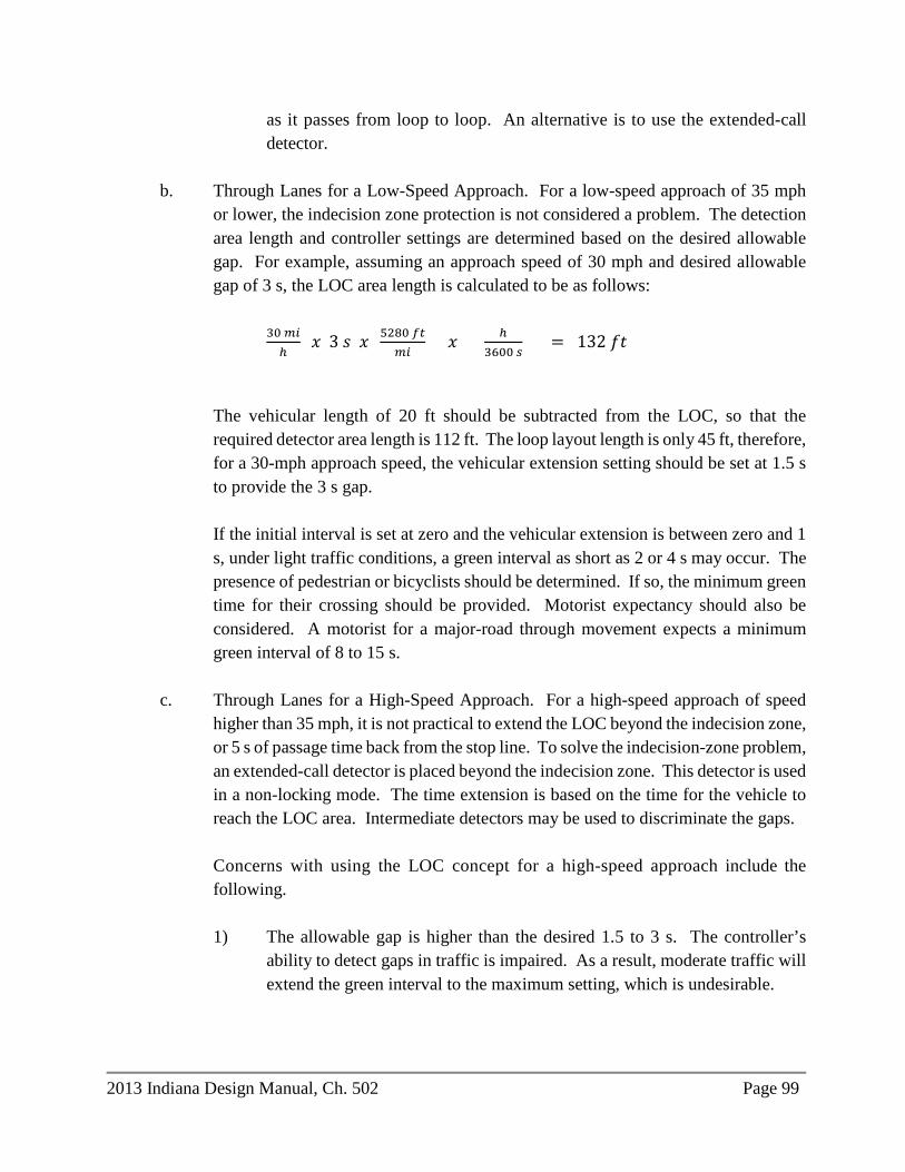
2013 Indiana Design Manual, Ch. 502 Page 99
as it passes from loop to loop. An alternative is to use the extended-call detector.
b. Through Lanes for a Low-Speed Approach. For a low-speed approach of 35 mph
or lower, the indecision zone protection is not considered a problem. The detection area length and controller settings are determined based on the desired allowable gap. For example, assuming an approach speed of 30 mph and desired allowable gap of 3 s, the LOC area length is calculated to be as follows:
30 𝑚𝑚𝑚𝑚ℎ
𝑥𝑥 3 𝑠𝑠 𝑥𝑥 5280 𝑓𝑓𝑓𝑓𝑚𝑚𝑚𝑚
𝑥𝑥 ℎ3600 𝑠𝑠
= 132 𝑓𝑓𝑡𝑡
The vehicular length of 20 ft should be subtracted from the LOC, so that the required detector area length is 112 ft. The loop layout length is only 45 ft, therefore, for a 30-mph approach speed, the vehicular extension setting should be set at 1.5 s to provide the 3 s gap.
If the initial interval is set at zero and the vehicular extension is between zero and 1 s, under light traffic conditions, a green interval as short as 2 or 4 s may occur. The presence of pedestrian or bicyclists should be determined. If so, the minimum green time for their crossing should be provided. Motorist expectancy should also be considered. A motorist for a major-road through movement expects a minimum green interval of 8 to 15 s.
c. Through Lanes for a High-Speed Approach. For a high-speed approach of speed
higher than 35 mph, it is not practical to extend the LOC beyond the indecision zone, or 5 s of passage time back from the stop line. To solve the indecision-zone problem, an extended-call detector is placed beyond the indecision zone. This detector is used in a non-locking mode. The time extension is based on the time for the vehicle to reach the LOC area. Intermediate detectors may be used to discriminate the gaps.
Concerns with using the LOC concept for a high-speed approach include the following.
1) The allowable gap is higher than the desired 1.5 to 3 s. The controller’s
ability to detect gaps in traffic is impaired. As a result, moderate traffic will extend the green interval to the maximum setting, which is undesirable.

Page 100 2013 Indiana Design Manual, Ch. 502
2) An LOC should be used only if the route’s ADT is 8,000 to 10,000. A high-speed approach with a higher volume is more efficiently served with a density controller. The intersection of a high-speed artery with a low-speed crossroad is more efficiently served with a density controller on the artery and an LOC for the crossroad.
502-3.04(11) Count Loops A new or modernized traffic signal should include count loops. These are inductive loop detectors that, in addition to detecting the presence or passage of a vehicle, provide a count pulse once a vehicle passes over the loops. The traffic-signal controller stores the counts in a format that can be uploaded either remotely or onsite to a personal computer. Detection devices appear on the Approved Products List of Traffic Signal and ITS Controller Equipment that are count-capable. The considerations for the layout of these detection devices for counting are similar to those for inductive loops. The configuration of count loops and determination of which loops are used to count vehicles at a signalized intersection are dependent on the geometry of the intersection. The considerations are as follows. 1. Encroachment. This occurs where a vehicle from one movement drives over the loops
providing vehicle count for another movement, causing that movement to over-count. Each lane with an encroachment issue should use only loop numbers 4 or 1 to count, depending on the extent of encroachment.
2. Late Entrance and Early Departure. This occurs where a vehicle enters or exits the side of a count loop series and does not cross every count loop in the series, causing that movement to under-count.
3. Lane Changes Within the Loop System. A vehicle changing lanes within 50 ft of the stop line is unpredictable and cannot be eliminated. This is a minor issue. For a lane where this is a major issue, count loops should be numbers 1 or 4, avoiding issues 1 and 2 above.
4. Truck and Trailer. A truck and trailer can be counted once or multiple times due to the difference in height of the bed and the axles. This is inconsistent between trucks, and variables cannot eliminate this issue. For a lane where this is a major issue, using all four loops as count loops can minimize over-counting.

2013 Indiana Design Manual, Ch. 502 Page 101
5. Shared Lane for Through and Right Movements. Figure 502-3CC shows two methods of counting through and right-turn movements where they share a lane. The minimum distance between the loops in the through lane and the loop in the radius for right-turning vehicles shall be 6 ft. Method A should be chosen if the radius is large enough that a right-turning vehicle will not cross the front loop in the lane. If a right-turning vehicle will pass partially or completely over the front loop in the lane, Method B should be used.
Figures 502-3CC and 502-3DD illustrate the effects of these factors and suggested count loop configurations.
502-3.04(12) Preferred Counting Configurations One loop will provide the most accurate count but at a higher cost in hardware and detector lead-ins than for a four-loop series. Some detectors are not as accurate with one loop. Two loops can increase accuracy for a detector that is not as accurate counting with one loop. Counting with two loops is equal in cost to counting with one loop of a four-loop series. Counting with two loops can decrease accuracy due to encroachment, late entrance, early departure, or lane changes within the count zone. Therefore, approval for counting with two loops shall be a District Office of Traffic decision. Four loops provide an accurate count installation with the lowest cost. However, this can decrease count accuracy if there are encroachments, late entrances, early departures, or lane changes within the count zone. The preferred counting configurations, listed from most to least desired, are as follows: 1. four loops: loops 1, 2, 3, and 4; 2. one loop: loop 4; 3. one loop: loop 1; 4. two loops: loops 3 and 4, requires district Office of Traffic approval; and 5. two loops: loops 1 and 2, requires district Office of Traffic approval. Only one movement can be counted per lane. As many movements should be counted at the intersection as feasible. 502-3.04(13) Computer Software

Page 102 2013 Indiana Design Manual, Ch. 502
Software programs are available to assist the designer in preparing traffic signal designs and timing plans. New programs and updates to existing programs, are being developed. These programs are used for the optimization of coordinated-signal systems, not basic controller settings. Before using these programs, the designer should contact the Traffic Control Systems Division to determine which software packages or versions INDOT is using. The following programs are used for signal timing optimization. 1. SYNCHRO®/SIMTRAFFIC®. SYNCHRO is a traffic-signal simulation program that
develops timing plans for isolated signal and arterial signal systems. It will optimize timings for fixed and actuated traffic signals. SIMTRAFFIC is a companion microscopic simulation and animation program that uses SYNCHRO files. Both programs will estimate measures of effectiveness for a timing plan.
2. PASSER II®. Progression Analysis and Signal System Evaluation Routine (PASSER II)
is a bandwidth-optimization program. It develops a timing plan that maximizes the through progression band along an arterial for up to 20 intersections. It functions in unsaturated traffic conditions and where turning movements onto the arterial are relatively light. PASSER II can also be used to develop arterial phase sequencing for input into a stop-and-delay optimization model such as TRANSYT-7F.
3. TRANSYT-7F®. The Traffic Signal Network Study Tool (TRANSYT-7F) develops a
signal-timing plan for an arterial or grid network. The objective of this program is to minimize stops and delays for the system as a whole, rather than maximizing arterial bandwidth.
4. AAP®. The Arterial Analysis Package (AAP) allows the user to access PASSER II and
TRANSYT-7F to perform an analysis and design of arterial signal timing. The package includes a user-friendly forms display program so that data can be entered interactively on a microcomputer. Through the AAP, the user can generate an input file for two component programs to evaluate arterial signal-timing designs and strategies. The package also links to the Wizard of the Helpful Intersection Control Hints (WHICH®) to facilitate design and analysis of individual intersections. The program interfaces with TRANSYT-7F, PASSER II, and WHICH.
5. HCS®. The Highway Capacity Software (HCS) replicates the procedures described in the
Highway Capacity Manual. It is a tool that increases productivity and accuracy, but it should be used only in conjunction with the Highway Capacity Manual and not as a replacement for it.

2013 Indiana Design Manual, Ch. 502 Page 103
6. PASSER III-98®. PASSER III-98 is a diamond-interchange optimization software. The program can evaluate existing or proposed signalization strategies, determine signalization strategies which minimize the average delay per vehicle, and calculate signal timing plans for interconnecting a series of interchanges on a one-way frontage road.
502-3.04(14) Maintenance Considerations After a signal is installed, the district will be responsible for its maintenance. Therefore, district personnel should be consulted early in the design process regarding the feasibility of the selected signal equipment and its location, e.g., controllers, cabinets, signal heads, etc. The selected equipment must satisfy the operator’s capability to adjust the signal and maintain it. For a signal on a local facility, it will be the responsibility of the local agency to operate and maintain the signal. The designer should review the local jurisdiction's existing traffic signal hardware and maintenance capabilities. If practical, the local jurisdiction’s existing hardware should be matched. This will reduce the municipality’s need for additional resources and personnel training. However, this should not limit the designer’s options, as there are engineering consultants who can assist a local agency in operation and maintenance of a traffic signal. 502-3.04(15) Traffic-Signal Loop Tagging Table The Loop Tagging Table, available for download from the Department’s Editable Documents page, shall be completed for the signalized intersection plan, including properly-identified loop numbers, vehicle directional movements with associated lane designations, phase assignments, individual loop numbers, and count output numbers. The completed Loop Tagging Table should be included in the Contract Information Book. Instructions for completing the Loop Tagging Table are also available for download from the Editable Documents page. 502-3.05 Coordinated-Signal-System Design Coordination is an enhanced mode which is used to provide progression through a system of two or more signals. Coordination can be achieved with either a timed-based coordination (TBC) system or a closed-loop system. A TBC system operates on an internal time clock which is used to automatically select timing plans based upon the time of day and day of week. In a closed-loop system, the signals are interconnected using cables or another communication mechanism.

Page 104 2013 Indiana Design Manual, Ch. 502
As traffic volume continues to increase, installation of coordinated signal systems should be used to improve traffic flow. By coordinating two or more traffic signals together, the overall capacity of the highway can be increased. Traffic signals which are 2600 ft or less apart should be considered for coordination. The use of a coordinated traffic signal system can satisfy the traffic needs of the highway for several years. It is also a relatively inexpensive method of improving capacity, thereby reducing delay, with minimal disruption to the highway as compared to the construction of additional lanes. Wireless communication is often used to enable data collection, monitoring, and adjustment of the system from a remote location. This is accomplished using either wireless cell modems or radio connection to an ITS network where available. 502-3.05(01) System-Timing Parameters The system-timing parameters used in a coordinated system include the following. 1. Cycle. The period of time in which a pre-timed controller, or an actuated controller, with
demand on all phases, displays a complete sequence of signal indications. The cycle length is common to all intersections operating together and is called the background cycle.
2. Split. The proportioning of the cycle length among the phases of the local controller. 3. Offset. The time relationship determined by the difference between a specific point in the
local signal sequence, the beginning of the major street green interval, and a system-wide reference point.
4. Time of Day or Day of Week. The time-of-day or day-of-week system selects system timing
plans based on a predefined schedule. The timing plan selection can be based not only on the time of day but also on the day of week and week of year. The selection of the plan can be based upon a specific day of the year.
5. Traffic Responsive. A traffic responsive system implements timing patterns based on
varying traffic conditions. This system selects from a number of predefined patterns. This system uses a computerized library of predefined timing patterns that are based on data collected by the system to develop the timing plan for the system.
502-3.05(02) System Types

2013 Indiana Design Manual, Ch. 502 Page 105
Methodologies are available to coordinate traffic signals. Most of these take advantage of computer technology. As new signal controllers, computers, and software are developed, the design of coordinated traffic signal systems will continue to improve. These systems should match existing systems or be coordinated with nearby systems. A traffic-signal system is designed by those who specialize in such systems. To maintain consistency, each traffic-signal-system design must be coordinated through the Traffic Control Systems Division. System types are described below. 1. Interconnected Time-of-Day System. The interconnected time-of-day system is applicable to
pre-timed and actuated controllers, in either a grid system or along an arterial system. The configuration for this type of system includes a field-located, timeclock-based master controller generating pattern selection and synchronization commands for transmission along an interconnecting cable or via radio modem. Local intersection coordination equipment interprets these commands and implements the desired timing.
An interconnected time-of-day system can use the physical interconnection solely for the purpose of synchronizing the timeclocks in the local controller. The local controller selects the desired timing from pre-programmed plans stored in the local controller.
2. Time-Base Coordinated Time-of-Day System. Operationally equivalent to the
interconnected time-of-day system, this type of system uses accurate timekeeping techniques to maintain a common time of day at each intersection without physical interconnection. Time-base coordination is tied to a 60 Hz AC power supply, with a battery backup if a power failure occurs.
Time-base coordination allows for the inexpensive implementation of a system, because the need for an interconnect cable is eliminated. However, a time-base system requires periodic checking by maintenance personnel, because the power company’s 60-Hz reference can be inconsistent. A power outage can affect only portions of a system, resulting in drift between intersections that continue to operate on power company lines and those that maintain time on a battery backup.
Time-base coordination can be used as a backup for a computerized signal system.
3. Traffic-Responsive Arterial System. The traffic-responsive arterial system concept is used
with semi-actuated controllers along an arterial. The field-located system master selects predetermined cycle lengths, splits, and offsets based upon current traffic flow measurements. These selections are transmitted along an interconnect cable or radio modem to coordination equipment at the local intersections.

Page 106 2013 Indiana Design Manual, Ch. 502
Cycle lengths are selected based on volume or occupancy level thresholds on the arterial where higher volumes correspond to longer cycles. Splits are selected based on the side-street volume demands. Offsets are selected by determining the predominant direction of flow along the arterial.
System sampling detectors, located along the arterial, input data back to the master controller along the interconnect cable or radio modem. The current system has the capability to implement plans on a time-of-day basis and through traffic-responsive techniques.
4. Distributed-Master, or Closed-Loop, System. The distributed-master, or closed-loop, system
advances the traffic-responsive arterial system by adding a communications link between the field-located master controller and an office-based microcomputer. The system is designed to interface with a personal computer over dial-up telephone lines. This connection is established only if the field master is generating a report or if the operator is interrogating or monitoring the system. With proper equipment, systems can share a single office-based microcomputer.
The system permits the maintenance of the controller database from the office. The controller’s configuration data, phase and timing parameters, and coordination patterns can be downloaded directly from the office.
The distributed-master system provides remote monitoring and timing plan updating capabilities for only a minor increase in cost. The increase consists of only the expense of the personal computer and the monthly costs of a business telephone or cell phone line. Graphics displays are provided to assist in monitoring the system.
5. Central Computer, or Interval-Command System. This system can control large numbers
of intersections from a central computer. This system requires constant communications between the central computer and each local intersection. The central computer determines the desired timing pattern parameters, based either on time-of-day or traffic-responsive criteria, and issues commands specific to each intersection once per second. These commands manipulate the controller into coordinated operation.
The system also monitors each intersection once per second. Detector data, current green phase, and other information is transmitted back to the computer for necessary processing. The system can include a large wall-size map display, with indicators showing controller and detector status and other informational displays, as well as a color graphics monitoring system.

2013 Indiana Design Manual, Ch. 502 Page 107
A system of this type requires a large minicomputer, complete with a conditioned, environmentally controlled computer room.
6. Central Database-Driven Control System. This system is based on the qualities of the
distributed-master system and the central-computer system. Although communications are maintained continuously with each intersection, timing pattern parameters are downloaded to each controller, eliminating most of the second-by-second approach. This allows a larger number of intersections to be controlled by a less powerful computer.
The reduction in communications data required also allows an increase in monitoring data being returned to the computer. Thus, the complex graphics displays in a distributed-master system can also be implemented in a large-scale system.
502-3.05(03) Communications Techniques Radio interconnection is the Department’s preferred communication method if the radio site survey is satisfactory. The use of other interconnection methods will be determined on a system-by-system basis. The district or the designer will conduct a site survey and submit the completed radio site survey report to the district traffic engineer. The radio site survey should be conducted with foliage on deciduous trees in the vicinity to ensure a minimum level of communications during the summer months. An approved digital Ethernet radio should be used for the survey. The Radio Site Survey Report form is available for download from the Department’s Editable Documents page. A copy of the radio site survey report should be included in the Contract Information book. The district or the designer will determine, based on the results of the radio site survey, what type of radio antenna should be used and the number of repeaters, if necessary, for the signal system. 502-3.06 Flashing Beacon A flashing beacon is used to alert road users to a specific condition, call attention to a specific sign, or provide a warning. 502-3.06(01) Intersection-Control Beacon

Page 108 2013 Indiana Design Manual, Ch. 502
An intersection-control beacon should be used where traffic or physical conditions do not justify conventional traffic signals, but where conditions indicate a hazard potential. IMUTCD Section 4L.02 provides guidance for the use of an intersection control flashing beacon. An intersection control beacon consists of one or more sections of a standard traffic signal head, having flashing, circular yellow or circular red indications in each face. Each intersection leg must have at least two indications. Indications should flash simultaneously. Supplemental indications may be required on one or more approaches to provide adequate visibility to approaching motorists. 502-3.06(02) Warning Beacon A warning beacon should be used only to supplement an appropriate warning or regulatory sign or marker. IMUTCD Section 4L.03 provides guidance for the use of a warning beacon. 502-3.06(03) Speed Limit Sign Beacon IMUTCD Section 4L.04 provides guidance for the use of a speed limit sign beacon. 502-3.06(04) Stop Sign Beacon IMUTCD Section 4L.05 provides guidance for the use of a stop sign beacon. 502-3.06(05) General Flashing Beacon Design A flashing-beacon unit and its mounting must satisfy the design requirements for traffic-control signals. These include the following: 1. Lens. Each signal unit lens should have a visible diameter of at least 12 in. The lens
must satisfy the ITE Standard for Adjustable Face Vehicle Traffic Control Signal Heads.
2. Sight Distance. While illuminated, the beacon should be visible to all motorists that it
faces for a distance of 1200 ft under normal atmospheric conditions, unless otherwise physically obstructed.

2013 Indiana Design Manual, Ch. 502 Page 109
3. Flashing. The flashing contacts should be equipped with filters for suppression of radio interference. A beacon must flash at a rate of at least 50 but not more than 60 flashes per minute. The illumination period of each flash should be between one-half and two-thirds of the total cycle. Where hazard identification beacons have more than one section, they may flash alternately.
4. Hours of Operation. A hazard identification beacon should be operated only during those
hours when the hazard or regulation exists, e.g., school opening or closing. See IMUTCD Part 7.
5. Traffic Signal. A flashing yellow beacon used with an advance traffic-signal warning sign
may be interconnected with a traffic-signal controller. 6. Alignment. If used to supplement a warning or regulatory sign, individual flashing-
beacon units should be horizontally or vertically aligned. The edge of the housing should be located no closer than 1 ft to the nearest edge of the sign.
7. Location. The obstruction or other condition warranting the beacon will govern the
location of the beacon with respect to the roadway. If used alone and located at the roadside, the bottom of the beacon unit should be at least 8 ft, but not more than 16 ft, above the pavement. If suspended over the roadway, the beacon clearance above the pavement should be at least 17 ft, but not more than 19 ft.
502-3.06(06) Pedestrian Hybrid Beacon A pedestrian hybrid beacon is used to warn and control traffic at an unsignalized location to assist pedestrians in crossing a street or highway at a marked crosswalk. IMUTCD Section 4F provides guidance for the design and use of a pedestrian hybrid beacon. 502-4.0 HIGHWAY LIGHTING 502-4.01 General The purpose of highway lighting is to provide a safe and comfortable environment for the night-time motorist. Due to the voluminous nature of highway-lighting-system design, it is impractical for this chapter to provide a complete highway-lighting-design guide. For additional design information, see the references listed in Section 502-4.01(01). The intent of this chapter is to

Page 110 2013 Indiana Design Manual, Ch. 502
provide the user with a synopsis of the highway-lighting-design process and to provide INDOT’s criteria, policies, and procedures regarding these issues. 502-4.01(01) References 1. AASHTO, An Informational Guide for Roadway Lighting; 2. FHWA, Roadway Lighting Handbook; 3. FHWA, Roadway Lighting Handbook, Addendum “Designing the Lighting System - Using
Pavement Luminance”; 4. Illuminating Engineering Society, Roadway Lighting, RP-8 (not used on an INDOT
project); 5. TRB, NCHRP Report No. 152, Warrants for Highway Lighting, (not used on an INDOT
project); 6. TRB, NCHRP Report No. 256, Partial Lighting of Interchanges, (not used on an INDOT
project); 7. Indiana Design Manual Chapter 49, Roadway Design; 8. AASHTO, Standard Specifications for Structural Supports for Highway Signs, Luminaires
and Traffic Signals; 9. INDOT Standard Drawings; 10. INDOT Standard Specifications; 11. National Electrical Code; 12. National Electric Safety Code; and 13. Highway Safety Manual. 502-4.01(02) Definitions of Terms 1. Average Maintained Illuminance. The average level of horizontal illuminance on the
roadway pavement once the output of the lamp and luminaire is diminished by the maintenance factors; expressed in average foot-candles for the pavement area.
2. Candela (cd). The unit of luminous intensity. 3. Candela per Square Foot (cd/ft2). The unit of photometric brightness, or luminance. The
unit is equal to the uniform luminance of a perfectly diffusing surface emitting or reflecting light at the rate of 1 lm/ft2 or the average luminance of a surface emitting or reflecting light at that rate.
2013 Indiana Design Manual, Ch. 502 Page 111
4. Effective Mounting Height. The vertical distance between the foundation of the light standard and the center of the light source in the luminaire.
5. Footcandle. The illuminance on a surface of 1 ft2 in area on which there is uniformly
distributed a light flux of 1 lm, or the illuminance produced on a surface for which all points are at a distance of 1 ft from a uniform point source of 1 cd.
6. Glare. The optical sensation produced by luminance within the visual field that is
sufficiently greater than the luminance to which the eyes are adapted and which causes annoyance, discomfort, or loss in visual performance and visibility.
7. Illuminance. The density of the luminous flux incident on a surface. It is the quotient of
the luminous flux divided by the area of the surface where the latter is uniformly illuminated.
8. Lamp Lumens Depreciation Factor (LLD). A depreciation factor that indicates the decrease
in a lamp’s initial lumen output over time. For design calculations, the initial lamp lumen value is reduced by an LLD to compensate for the anticipated lumen reduction.
9. Longitudinal Roadway Line. A line along the roadway parallel to the curb or shoulder line. 10. Lumen (lm). A unit of measure of the quantity of light. 11. Luminaire. A complete lighting unit consisting of a lamp or lamps together with the parts
designed to distribute the light, to position and protect the lamps, and to connect the lamps to the power supply.
12. Luminaire Dirt Depreciation Factor (LDD). A depreciation factor that indicates the
expected reduction of a lamp’s initial lumen output due to the accumulation of dirt on or within the luminaire over time.
13. Luminance. The luminous intensity of a surface in a given direction per unit of projected
area of the surface as viewed from that direction. 14. Maintenance Factor (MF). A combination of light-loss factors used to denote the reduction
of the illumination for a given area after a period of time compared to the initial illumination on the same area. MF = LLD x LDD.
15. Mounting Height. The vertical distance between the roadway surface and the center of the
light source in the luminaire.

Page 112 2013 Indiana Design Manual, Ch. 502
16. Nadir. The vertical axis which passes through the center of the luminaire light source. 17. Spacing. The distance in feet between successive lighting units. 18. Transverse Roadway Line. A line across the roadway that is perpendicular to the curb or
shoulder line. 19. Uniformity Ratio. The ratio of average maintained lux of illuminance on the pavement to
the maintained lux at the point of minimum illuminance on the pavement. A uniformity ratio of 3:1 means that the average lux value on the pavement is three times the lux value at the point of least illuminance on the pavement.
502-4.01(03) State and Local Responsibilities The following describes the responsibilities shared between the Department and a local public agency for a lighting installation along a state-maintained highway. 1. INDOT Jurisdiction. The Department may illuminate a portion of a state, U.S., or interstate
highway outside incorporated city or town limits that satisfies the warranting conditions provided in Section 502-4.02. INDOT will not provide illumination inside city or town incorporated limits, except along an interstate route and at a roundabout as described in item 3 below.
2. Local Jurisdiction. A local public agency may install lighting along a state highway within
its jurisdictional limits provided the agency finds sufficient benefit in the form of convenience, safety, policing, community promotion, public relations, etc. The local agency will develop appropriate warranting guidelines for installing lighting. If the city or town has not developed warrants, the Department warrants described in Section 502-4.02, or those listed in the references in Section 502-4.01(01), should be considered. The local agency will be responsible for installing, maintaining, and operating the lighting facilities. The plans for lighting a state highway within local jurisdictional limits must satisfy Department criteria and must receive INDOT approval through a formal contract prior to installation. The plans and specifications should be submitted for review to the Highway Design and Technical Support Division.
A federally-funded, local agency project with decorative lighting structures or other non-
standard lighting equipment that has not received proprietary-item approval will require full

2013 Indiana Design Manual, Ch. 502 Page 113
funding by the local agency. Prior to contract document submission, the local agency must enter into a fully-executed contract with the Department for the non-participating pay items.
3. Roundabout. INDOT will provide and assume operational responsibility for lighting at a
roundabout and on its approaches with the following exceptions. a. While INDOT does not normally provide lighting for the exiting lanes, the local
agency may request such lighting. The local agency will enter into an agreement with INDOT stipulating that it will provide funding for the additional installation costs, and that it will assume the energy costs for the entire system. INDOT will provide maintenance.
b. If the local agency requests decorative poles, decorative fixtures, or an alternative lighting technology such as LED, plasma, induction, etc., it will enter into an agreement to reimburse INDOT for additional installation costs and to assume energy costs and maintenance responsibilities for the life of the system.
4. Installation. Installation by the Department will be done under the Department’s
programming and contracting procedures. The installation, however, may be performed through a contract with a utility company.
5. Operation. For each location where the Department is responsible for paying the energy
costs, a contract must be negotiated between the local utility company and the Department for payment for the electrical current. The current may or may not be metered. All bills should be submitted through the district office.
6. Maintenance. Maintenance of a department lighting system may be furnished by contract
with a local utility company, by an independent lighting contractor, or by trained INDOT personnel.
7. Contract. A contract for a department lighting system should be prepared according to
INDOT contract policy. According to Indiana Code, IC 8-23-22-2, the Department is required to enter into a contract for sharing the utility costs.
8. Existing System. Where a contract between INDOT and a local agency on maintenance and
operation of an existing lighting system along a state-maintained highway cannot be resolved, the following will apply.
a. If a system installed by the Department is annexed into city or town corporate limits
and the local agency does not agree to take over the maintenance and operation costs,

Page 114 2013 Indiana Design Manual, Ch. 502
the system should be considered for removal if a cost analysis shows such action to be cost effective. A removal study as defined in Section 502-4.02(11) should be conducted.
b. If the system was installed by the local agency and the local agency is no longer
willing to pay for the operation and maintenance costs, INDOT will determine if the system is warranted. If it is warranted and is outside the incorporation limits, the Department may take over the responsibilities for maintaining and operating the system. If the system is not warranted, the local agency can be requested to remove the system. If the local agency will not remove the system, the Department may remove it as described in Section 502-4.02(11).
c. If the system was installed in accordance with a contract entered into between the
Department and the local governmental agency, and the agency is no longer abiding by the stipulations of the contract, the Department may conduct a study to determine if the system is warranted. If continuation of the system is not determined to be cost effective, INDOT may remove it as described in Section 502-4.02(11).
9. Other Construction Project. Where a proposed project, e.g., roadway reconstruction, is
within city or town incorporation limits, the following will apply relative to lighting.
a. If the existing lighting system is owned by the local agency and the project requires the system to be relocated, INDOT will be responsible for all relocation expenses.
b. If the existing lighting system is owned by a utility company and the project requires
the system to be relocated, the utility company will be responsible for all relocation expenses.
c. If there is no existing lighting and it is requested by the local agency, INDOT will
include the lighting system in the project if the local agency agrees to pay for all installation costs and will assume responsibility for the operation and maintenance of the system.
d. If the existing luminaire arms are mounted on utility company poles and the lighting
hardware is owned by the local agency, INDOT will be responsible only for the relocation expenses associated with the lighting hardware, if requested by the local agency. No upgrades in the existing lighting are accomplished under this option.
2013 Indiana Design Manual, Ch. 502 Page 115
502-4.01(04) Lighting Studies If a request is made for a new lighting installation along a state-maintained highway outside of incorporation limits, the following procedure should be used. 1. Lighting Request. The local agency or other local group seeking the lighting system is
required to submit a request to the district Traffic Office petitioning the Department to consider the installation of a new lighting system along the state highway.
2. Lighting Study. The designer will conduct a study to determine if the request justifies
further action. Each lighting study report should include the Highway Lighting Accident Warrant Analysis.
3. Programming. If the location warrants lighting and it is outside the corporate limits, the
District Traffic Office will request the Planning Division to initiate a project to provide lighting at the location.
502-4.02 Warrants Providing lighting along every highway is not practical or cost effective. The District Traffic Team will be responsible for determining if the lighting system is economically justified along a state-maintained highway. An editable version of the Highway Lighting Accident Analysis Worksheet is available for download from the Department’s website at www.in.gov/dot/div/contracts/design/dmforms/. It is the Department’s practice to provide lighting only if the warrants described herein are satisfied. A location which satisfies these warrants does not obligate INDOT to provide funding for the requested highway lighting project. INDOT’s objective is to identify each roadway which should be considered in the process of setting priorities for the allocation of available funding to a roadway-lighting project. Local officials may determine the feasibility of providing lighting on a state highway within city or town limits. 502-4.02(01) Warrant Criteria for Freeways Freeway lighting should be considered where the night-to-day ratio of crashes is greater than 0.5 and the lighting is expected to be cost effective.

Page 116 2013 Indiana Design Manual, Ch. 502
In addition, warrant CFL-2 and CFL-3 of the AASHTO Roadway Lighting Design Guide may be considered. 502-4.02(02) Warrant Criteria for Interchanges Interchange lighting should be considered where the night-to-day ratio of crashes is greater than 0.5 and the lighting is expected to be cost effective. In addition, AASHTO Roadway Lighting Design Guide warrants CIL-1 and CIL-2 for complete interchange lighting and warrant PIL-1 for partial interchange lighting may be considered. 502-4.02(03) Warrant Criteria for Non-Freeways [Rev. Jan 2016] Non-freeway lighting should be considered where the night-to-day ratio of crashes is greater than 0.5 and the lighting is expected to be cost effective. In addition, lighting should be considered for locations with a relatively high potential for crashes, such as a section with numerous driveways, channelized islands, significant commercial or residential development, a high percentage of trucks, nighttime pedestrian volumes, or geometric deficiencies such as substandard stopping sight distance. Where a state-maintained highway intersects with or closely parallels local streets with existing lighting or which may have future lighting, provisions should be made for possible future illumination on the state-maintained highway. 502-4.02(04) Criteria for Highway-Sign Lighting Sign lighting will be provided only where it is determined by the District Traffic Office that the reflective sign sheeting by itself is not sufficient for nighttime visibility. 502-4.02(05) Criteria for Rest Area Lighting will be provided for all areas within a rest area that have pedestrian activities. Rest area ramps are also lighted, especially if continuous lighting is provided on the freeway. Highway-type light standards and luminaires should be used to light the parking areas and the ramps.

2013 Indiana Design Manual, Ch. 502 Page 117

Page 118 2013 Indiana Design Manual, Ch. 502
502-4.02(06) Criteria for Truck Weigh Station Each permanent truck weigh station should be lighted where weighing will occur after daylight hours. Highway-type light standards and luminaires should be used to light the weighing area, parking areas, speed change lanes, and ramps. Lighting may be provided for the sign preceding a truck weigh station which indicates that the station is open or closed. 502-4.02(07) Criteria for Bridge Structure The following should be considered when determining the need for lighting on a bridge structure. 1. Lighted Approaches. Lighting should be placed across or under a bridge where one or both
approaches have or are planned to have lighting. Ownership of the lighting will be determined in the same manner as for a roadway.
2. Geometrics. Lighting can be considered for a long, narrow bridge, though the approaches
are not lighted. Lighting should be considered where there is unusual or critical roadway geometry under or adjacent to the underpass area.
502-4.02(08) Criteria for Tunnel or Underpass [Rev. Jan. 2016] The lighting of a tunnel or underpass should be in accordance with the AASHTO Roadway Lighting Design Guide. Lighting of underpasses that are less than 75 ft in length is not normally needed. Daytime lighting should be considered for tunnels or underpasses with a length to height ratio that exceeds 10:1. ANSI/IESNA RP-22-11 publication on American National Standard Practice for Tunnel Lighting contains additional information. 502-4.02(09) Criteria for Roundabout [Rev. Jan. 2016] The lighting of a roundabout should be in accordance with the AASHTO Roadway Lighting Design Guide and NCHRP Report 672. Lighting at the roundabout should include the central circulatory roadway and extend at least 400 ft from the circulatory roadway along all approaches. Lighting on the approaches should also extend through any pedestrian crosswalks and/or splitter islands. The remaining limits of the intersection can be delineated with RPM’s or by other methods.
2013 Indiana Design Manual, Ch. 502 Page 119
502-4.02(10) Criteria for Other Facilities Lighting should be considered at the following locations: 1. commuter park-and-ride lot; 2. bikeway; 3. walkway; or 4. other pedestrian facility. The need for lighting at one of these locations will be determined as required for each situation. See the AASHTO Roadway Lighting Design Guide for information on the lighting of walkways/bikeways separated from the roadway. 502-4.02(11) Reduction or Removal of Lighting [Rev. Jan. 2016] Where an existing highway lighting system is no longer warranted, feasible, or cost effective, it should be considered for reduction in the lighting level or for removal. Where light levels are reduced, they should not be reduced below the criteria described in Figure 502-4E. Prior to reducing lighting or removing the system, an engineering investigation will be required. Concurrence by the Highway Design and Technical Support Division and approval by the Commissioner will be required. If federal-aid funds were used for the original installation and the project is on the National Highway System and is not exempt from FHWA oversight, a copy of the report should be submitted to the FHWA. If determining whether an existing lighting system should be removed or the lighting reduced, the following should be considered. 1. Freeway Lighting. Continuous freeway lighting should be removed or reduced where a cost
analysis shows that such action will be cost effective. The cost analysis will be similar to the one prepared for the installation of a new lighting system. However, this study must consider the increase in accidents and cost to remove the system. A 50% increase in nighttime accidents should be assumed over a period of three years for analysis purposes.
2. Interchange Lighting. Complete interchange lighting should be reduced to partial
interchange lighting where the average traffic volume falls below the levels given in the AASHTO Lighting Design Guide, table 3-3, both cases CIL-1 and CIL-2, but satisfies that shown in table 3-4, case PIL-1. An engineering analysis will be required to determine the extent of lighting reduction. Removal of complete or partial lighting will require a cost analysis to determine the cost effectiveness of removing the lighting system. A 50% increase in nighttime accidents should be assumed for analysis purposes.

Page 120 2013 Indiana Design Manual, Ch. 502
3. Non-Freeway Lighting. Where lighting is no longer warranted on a non-freeway section, a
benefit/cost analysis should be conducted to confirm that the lighting is no longer warranted. Section 502-4.01(03) item 7 describes the procedure for removal of lighting if the local agency no longer can or is willing to pay the maintenance and operation costs for the lighting system.
4. Obsolete or Substandard System. Where it has been determined that a lighting system is
obsolete, substandard, or is beyond its useful service life, it should be removed, replaced, or modified. An engineering investigation should be conducted to determine the appropriate action. If removal is considered, local input should be included in the investigation. A new replacement system should be installed only if it satisfies the warrants for a new system. Current accident data may be used for the analysis. However, the data should be adjusted to reflect the expected increase in accidents if the system is removed.
To study the effects of removing or reducing lighting, the Department may turn off part or all of the system. This may only be performed after an engineering analysis has been conducted to determine the expected effect of turning the lights off. This study period should not be less than one year or more than four years. After the study has been completed, the system may be either re-energized or removed. After the decision has been made to remove or reduce the level of highway lighting, the lights should be turned off but left in place for a period of at least one year and not longer than four years. An accident analysis study will be required during this time period to determine the effects of the reduced lighting. A final cost analysis will be required with the updated accident and capital-improvement data. A system removal will be accomplished either by state forces or by a contractor as part of other project work. 502-4.03(12) Alternative criteria for urban streets [Added Jan. 2016] Local agencies may refer to NCHRP Report 152, Highway Lighting Warrants for a thorough methodology to determine need for lighting on existing facilities. 502-4.02(13) Transition Lighting [Added Jan. 2016] Where light levels are significant consideration should be given to providing a gradual transition to segments that are not lighted. See ANSI/IESNA RP-8. 502-4.02(14) Adaptive Lighting [Added Jan. 2016]

2013 Indiana Design Manual, Ch. 502 Page 121
The fundamental concept of adaptive lighting is to provide lighting only when and where it is needed, essentially managing the roadway light level as an asset. Refer to Publication No. FHWA-HRT-14-050, dated June 2014 for more information. Adaptive lighting may involve lighting curfews, or reduction of lighting during periods of low demand, e.g. from 1 a.m. to 4 a.m. 502-4.03 Lighting Equipment A number of options are available in selecting luminaire equipment that will satisfy the desired design criteria. Figure 502-4A, Typical Light-Pole Installation, provides an illustration of the parts of the lighting standard and luminaire. In addition to the INDOT Standard Drawings and the INDOT Standard Specifications, the following provides guidance regarding INDOT’s approved lighting equipment. The selected equipment should be determined to be in accordance with standard hardware designs. Specialized equipment and designs can increase the installation and maintenance costs, thereby reducing the cost effectiveness of the lighting system. 502-4.03(01) Foundation Upon determining the foundation design, the following should be considered. 1. Material. Each foundation for a permanent installation should be concrete class A. It may
be either cast-in-place or precast. 2. Design. The INDOT Standard Drawings provide the details for depth, width, reinforcing,
etc., for both conventional and high-mast light standards. For a high-mast foundation, a soil survey is required to determine if additional support is required.
3. Placement and Grading. The INDOT Standard Drawings and Section 502-4.06(05) provide
the criteria for the placement of a light standard relative to the roadway and ditch lines. They also provide criteria for grading around the light standard foundation.
502-4.03(02) Light Standard or Pole A factor in highway lighting design is the selection of the luminaire and the mounting height. A higher mounting height will reduce the number of light standards required. The INDOT Standard Specifications and the AASHTO Standard Specifications for Structural Supports for Highway

Page 122 2013 Indiana Design Manual, Ch. 502
Signs, Luminaires, and Traffic Signals provide the Department’s criteria for light standards. The following describes the light standards used by the Department. 1. Conventional. This type of pole is used most often. It has a mounting height ranging from
30 ft to 50 ft. INDOT practice is to use a light pole with a mounting height between 40 ft and 50 ft. The recommended minimum mounting height is 40 ft. Details for conventional light poles appear in the INDOT Standard Drawings.
2. High-Mast. A high-mast pole can range from 80 ft to 200 ft in height. This type should be
used where there is a large area that requires lighting, e.g., interchange. The use of high-mast lighting and higher-wattage lamps reduces the number of poles, yet retains the quality of the lighting. High-mast lighting should be considered where practical. Details for high-mast towers appear in the INDOT Standard Drawings.
3. Materials. Light standards for a permanent installation are made of galvanized steel,
stainless steel, or aluminum. Wood poles are used as service poles or for temporary lighting, e.g., in a construction zone.
4. Base. Unless otherwise protected, a breakaway base should be provided for each light pole
within the clear zone along a rural or high-speed urban highway. However, where pedestrians are present, a breakaway base should not be used. Section 502-4.06(05) provides additional criteria on the appropriate application of where to use a breakaway or non-breakaway base. Each breakaway base should be in accordance with the AASHTO Standard Specifications for Structural Supports for Highway Signs, Luminaires, and Traffic Signals. The base types include the following.
a. Breakaway Transformer Base. A transformer base consists of an aluminum apron
between the concrete foundation and the base of the pole. The breakaway transformer base is designed to be struck by a car’s bumper. Once hit, the base deforms and breaks away. All wiring inside the base must also be connected to the breakaway device. The cast-aluminum transformer base should be used.
b. Non-Breakaway Steel Transformer Base. A steel transformer base is similar in
design to an aluminum base. However, it is not in accordance with the AASHTO breakaway criteria. Section 502-4.06(05) discusses the appropriate locations where a breakaway base is not required.
c. Breakaway Support Coupling. A breakaway support coupling is an aluminum
connector or sleeve which is designed to shear once the pole is hit. The bottom of the coupling is threaded onto the foundation anchor bolts, and the light standard is

2013 Indiana Design Manual, Ch. 502 Page 123
attached to the top of the coupling. Four couplings are used with each light standard. The support coupling length is 5 in.
d. Anchor Base. An anchor base is a metal plate which is welded to the bottom of the
luminaire support. The plate allows the post to be bolted to the foundation without an intermediate breakaway device or to a breakaway coupling, slip plate, or transformer base.
5. Structural Design. Each light standard should be designed in accordance with the structural
design criteria described in the INDOT Standard Specifications, including the criteria for wind loading, maximum horizontal deflection, maximum stresses, luminaire loads, material strengths, welds, bolts, etc.
6. Effective Mounting Height. A light standard must be constructed so that it provides a
luminaire mounting height above the roadway pavement as shown in Figure 502-4A, Typical Light-Pole Installation. After determining the mounting height, the appropriate pole length can then be determined.
7. Lighting Location Identification Numbering System.
Lighting identification numbers should be incorporated into the plans and should be determined as follows:
a. Overall Numbering Format.
1) The first set in the identification is the county number in which the lighting system is located.
2) The county number is followed by a 1-, 2-, or 3-digit route number of the
mainline route or major road on which the system is located. 3) The mainline route number is followed by the cross road number.
If the cross road is a numbered route on the state highway system the 1-, 2-, or 3-digit route number of the cross road should be used. If the cross road is not a numbered state highway system route then a special identifier is needed for the county road, city street, exit number, rest area or weigh station. See item 7.b for details.
4) The last set is the 1-, 2-, or 3-digit number specifying the individual pole,
sign, or underpass location.
Page 124 2013 Indiana Design Manual, Ch. 502
b. Specialized Numbering for Cross Roads that Are Not Numbered State Routes.
1) Intersection of an Interstate Route and a County Road or City Street.
The cross road should be labeled with “EX” (for exit) as a special identifier followed by the mile marker exit number of the interchange.
2) Intersection of S.R. or U.S. Route and a County Road. The cross road special identifier should be “CR” (for County Road) followed
by the county road number. 3) Intersection of S.R. or U.S. Route With a City Street. The first two letters of the city’s name should be used as the special identifier
followed by a three- or four-letter abbreviation of the crossroad’s name. 4) Rest Area Located on the Interstate. “NR”, “SR”, “ER” or “WR” (for northbound rest area, southbound rest area,
eastbound rest area or westbound rest area respectively) should be used as the special identifier followed by the 1-, 2-, or 3-digit mile marker number closest to the rest area.
5) Rest Area Located on a S.R. or U.S. Route.
“RA” should be used as the special identifier followed by a three- or four-
letter abbreviation of the rest area’s name.
6) Weigh Station Located on the Interstate.
“NW”, “SW”, “EW” or “WW” (for northbound weigh station, southbound weigh station, east bound weigh station, or westbound weigh station respectively) should be used as the special identifier followed by the 1-, 2-, or 3-digit mile marker number closest to the weigh station.
7) Weigh Station Located on a S. R. or U.S. Route.

2013 Indiana Design Manual, Ch. 502 Page 125
The special identifiers are to be used in the same manner as for weigh station on interstates routs with the exception that instead of using a 1-, 2-, or 3-digit mile marker numbers, there will be a four-letter unique identifier created for that particular weigh station.
When more than two routes intersect at a location, only the two most primary or major route numbers shall be used to identify the location. When two routes intersect more than once in a county, then the letters “NJ”, “SJ”, “EJ” or “WJ” shall be used after the 1-, 2-, or 3-digits of the crossroad route number and before the hyphen to indicate that a given intersection is the north junction, south junction, east junction, or west junction respectively.
502-4.03(03) Mast Arm A mast arm allows placement of the light source near the edge of the travel lane. The use of a longer mast arm is recommended, although the initial costs may be higher. A longer mast arm allows the pole to be placed farther from the traveled way, thus providing a safer roadside environment. Otherwise, the use of a longer mast arm can have a negative effect on the loading capabilities of the base. In addition to the INDOT Standard Specifications, the following provides information and design guidance regarding the use of a mast arm. 1. Material. Mast arms are made of the same material as the light standard. 2. Mast Arm. The following should be used to determine the appropriate mast-arm type.
a. Less than 8 ft. This may be either of the single-member or the truss-type design.
The design should be consistent with other nearby mast arm types.
b. 8 ft or Longer. This should be of only the truss-type design. 3. Mast-Arm Length. The length of the mast arm should be such that the luminaire is placed
over the center of the width of the shoulder. 4. Bridge. Each mast arm for a bridge-deck light standard should be of the truss-type design. 5. Rise. Figure 502-4B, Mast-Arm Rise, provides the maximum rise that should be used, based
on the mast-arm length. See Figure 502-4A for Typical Light-Pole Installation and illustration of Mast-Arm Rise.

Page 126 2013 Indiana Design Manual, Ch. 502
502-4.03(04) Luminaire [Rev. Jan. 2016] A luminaire is defined as a complete lighting unit consisting of a lamp or lamps together with the parts designed to distribute light. The INDOT Standard Specifications, along with the following, provide the Department’s criteria for luminaire hardware. Section 502-4.06(03) item 1 discusses the light distributions for a luminaire. For additional information, the designer should contact the Traffic Administration Manager, Traffic Engineering Division for the latest products and specifications. 1. Light Source. Only a high-intensity discharge light source should be used. The following
provides information on the light sources that may be used.
a. High-Pressure Sodium (HPS). The HPS lamp produces a soft, pinkish-yellow light by passing an electric current through a sodium-and-mercury vapor.
b. Low-Pressure Sodium (LPS). Its disadvantage is that it requires long tubes and has
poor color quality. INDOT does not allow the use of LPS on a state facility. However, a local agency can consider the use of an LPS lighting source. The LPS lamp produces a yellow light by passing an electrical current through a sodium vapor.
c. Metal Halide (MH). A metal-halide lamp produces color at higher efficiency than a mercury vapor (MV) lamp. However, life expectancy for a traditional MH lamp is shorter than that for an HPS or MV. An MH lamp is also more sensitive to lamp orientation than other light sources. The traditional MH luminaire is used for lighting a sports arena or major sports stadium, for high-mast lighting, or for lighting a downtown area or park. Metal Halide luminaires utilizing solid state ballasts are viable options for general roadway applications. Metal halide produces good color rendition. Light is produced by passing a current through a combination of metallic vapors.
d. Light Emitting Diode (LED). LEDs are arranged in clusters which are attached to a panel. Various designs utilize different LED types Heat sinks are built into the housing to facilitate heat dissipation and maximize luminaire service life. Light is directly emitted from the lens, so reflectors are not required, resulting in the light being delivered more efficiently than the HPS type and also resulting in less light pollution. LEDs are energy efficient, have a long life, and generate a full color spectrum resulting in good color rendition. Due to the manner in which light is emitted the arrays must be carefully arranged to provide sufficient light distribution

2013 Indiana Design Manual, Ch. 502 Page 127
and yet be energy efficient. Properly arranged LEDs can provide energy efficient, effective light distribution.
LED retrofits are available for existing high mast luminaires. LED modules are attached to a threaded rod which is fit into the existing housing. Luminaire dimensions should be verified as housing diameters less than 16 inches may require an attachment plate as well as the threaded rod, pending the retrofit manufacturer’s specific design.
e. Light Emitting Plasma. Plasma lamps generate light by exciting gas with radio frequency power. They produce visible light without phosphor conversion which results in a higher luminaire efficiency and which eliminates color shift. The point-source light they generate results in an even distribution of light through highly efficient optics. Plasma luminaires have no electrodes which reduces maintenance requirements. They are highly efficient, have a long life, and generate a full color spectrum resulting in good color rendition. Heat sinks are built into the housing to facilitate heat dissipation and maximize luminaire service life.
f. Induction Lighting. Magnetic induction lamps also contain no electrodes resulting in an extended service life. The power used to generate light is transferred from outside the lamp to inside via electromagnetic fields. Induction lamps are also efficient light generators compared to HPS lamps.
2. Optical System. The optical system consists of a light source, a reflector (except for LED),
and also a refractor (or lens for LED).
a. Light Source. Item 1 above discusses light sources that should be considered.
b. Reflector. The reflector is used in optical control to change the direction of the light rays. Its purpose is to take that portion of light emitted by the lamp that otherwise will be lost or poorly utilized, and to redirect it to a more desirable distribution pattern. A reflector is designed to work either alone or with a refractor. Reflectors are specular or diffuse. A specular reflector is made from a glossy material that provides a mirror-like surface. A diffuse reflector is used where the intent is to spread the light over a wider area.
c. Refractor. The refractor is another means in optical control to change the direction
of the light. A refractor is made of transparent high-strength glass or plastic. Plastic is used in a high-vandalism area. However, plastic can yellow over time due to heat

Page 128 2013 Indiana Design Manual, Ch. 502
and ultraviolet exposure. The refractor, through its prismatic construction, controls and redirects both the light emitted by the lamp and the light reflected off the reflector. It can also be used to control the brightness of the lamp source.
3. Ballast/Power Driver. Each luminaire must operate with an input voltage variation of ±10%
of the rated operating voltage specified, with non-solid state technologies this is accomplished through a built-in ballast. A ballast is used to regulate the voltage to the lamp to ensure that the lamp is operating within its design parameters. It also provides the proper open-circuit voltage to start the lamp. The ballast should be an auto-regulator type. Figure 502-4C, Lamp Data, provides the approximate expected operating wattage for a ballast based on the lamp wattage.
For solid state technology luminaires the input voltage is controlled by a power driver. Power drivers are completely electronic and are considered to be the controlling component in the performance and service life of the luminaire. Electronic power drivers allow for the light source to be dimmed so they provide an opportunity to reduce energy consumption through adaptive lighting (reduced light levels after a certain time at night).
4. Housing Unit. Luminaire housing requirements are dependent upon the application type.
In selecting a luminaire housing, the following should be considered.
a. Roadway-Lighting Luminaire. The housing unit should allow access from the street side and allow for adjustments to the light. The luminaire should also have a high-impact, heat-resistant, glass, or plastic prismatic refractor.
Since LEDs generate a substantial amount of heat and since they are sensitive to heat
buildup, their housings are provided with apparatus known as heat sinks to dissipate heat in an effective manner. The typical heat sink is a shape or plate placed in contact with the LED panel. The shape or plate is usually made of a conductive metal such as aluminum.
b. Sign Luminaire. A sign luminaire requires the same housing as a roadway-lighting
luminaire, except that it should also provide a durable, plastic, vandal-resistant shield that blocks the view of the refractor from an approaching motorist. The unit is attached to the sign walkway as shown on the INDOT Standard Drawings. The mounting attachment is adjustable to allow for directing the light onto the sign.

2013 Indiana Design Manual, Ch. 502 Page 129
c. Underpass Luminaire. An underpass luminaire requires the same housing as a roadway-lighting luminaire, except that it should also provide a durable, plastic, vandal-resistant shield. The ballast should be placed as shown on the INDOT Standard Drawings. An underpass luminaire may be attached to the vertical-side surface of a bridge bent structure, or may be suspended by the use of a pendant.
d. High-Mast Luminaire. A high-mast luminaire is an enclosed unit with a reflector
and a borosilicate glass refractor. The luminaire is attached to the mast ring. The mounting attachment is adjustable to allow for directing the light.
5. Backlight, Uplight, and Glare (BUG) Rating. I.E.S.N.A. has recently adopted a system of classifying the amount of light that is generated in three distinct directions from the luminaire. The BUG rating system is an alternative to the conventional “cut-off” system as a means of classifying light distribution. Backlight is defined as the light distributed away from the street (towards sidewalk, shoulder, etc.) and below the luminaire. Uplight is the amount of light that is directed above the luminaire either to the front or back. Glare, or offensive light, results from light distributed to the street side below the luminaire and towards the driver at an acute angle from the luminaire (less than 30 degrees from horizontal).
BUG ratings can be specified to limit or control the amount of glare, sky glow and light trespass effecting the environment of the lighting system. For example for locations adjacent to observatories and planetariums it may be desirable to keep the amount of uplight to a minimum thereby reducing sky glow and interference with astronomical observations. In urban settings a certain amount of backlight on sidewalk and parking lot areas may be desirable for added security. For luminaires mounted at lower heights (less than 30 ft) the designer should consider models with a glare rating no greater than 3. Each of the three ratings is on a scale of 0 to 6, higher the number the greater the affect. For additional information on the BUG rating system refer to the following I.E.S.N.A. publication: https://www.ies.org/pdf/education/ies-fol-addenda-1-%20bug-ratings.pdf.
502-4.03(05) Other Equipment [Rev. Jan. 2016] In developing a highway-lighting system, the equipment component can affect the design of the system. The elements include the following and are addressed in the INDOT Standard Drawings, the INDOT Standard Specifications and the manufacturer’s criteria.

Page 130 2013 Indiana Design Manual, Ch. 502
1. Electric Components. See Section 502-4.03(04) for a discussion of electrical components for various light sources, including ballasts, fuses, photoelectric controls, wiring, conduit, handholes, connections, breaker boxes, circuit breakers, relay switches, etc.
2. High-Mast Light Standard. The components include the luminaire ring assembly for
attaching a luminaire, head frame assembly, winch assembly, external drive system used to lower the luminaire for maintenance, cable terminator, and lightning rod.
3. Utility Service. Since many electric providers have not yet adopted a flat billing rate for solid
state light sources when solid state is to be used the designer should consider specifying a metered service so that the owner may better realize the benefit of reduced energy consumption. This will involve coordination with the electric provider and either the district office or the agency of jurisdiction.
502-4.04 Lighting Methodologies The lighting-design methodologies are those for illuminance, luminance, and small-target visibility. The Illuminating Engineering Society (IES) of North America has been the leader in the development of these procedures. Only the illuminance methodology should be used in the design of highway lighting. For additional information on these procedures, see the references listed in Section 502-4.01(01). 502-4.04(01) Illuminance Illuminance is defined as the density of the luminous flux incident on a surface measured in footcandles. The methodology is concerned with the measurement of the light’s intensity striking a particular point on the pavement. The brightest spot will occur directly under the luminaire and diminish the farther a motorist is away from the source. The disadvantage of this methodology is that one does not see incident light, but instead sees the light reflected from an object or surface. This sensation is known as brightness, with objects distinguished by the difference in brightness or contrast. Brightness can be expressed mathematically as luminance, or the luminous intensity per unit area directed towards the eye. The factors in illuminance methodology are the measurement of average maintained horizontal illumination, Eh, and the uniformity ratio of the average-maintained illuminance to the minimum-maintained illuminance.

2013 Indiana Design Manual, Ch. 502 Page 131
502-4.04(02) Luminance Luminance is defined as the luminous intensity of a surface in a given direction per unit of projected area of the surface as viewed from that direction. It is measured in candelas per square foot. The luminance methodology is concerned with the measurement of light from the luminaire reflecting off the pavement surface to the motorist’s eyes. This measurement is affected by the pavement’s reflectivity characteristics. To obtain the lighting measurements for the roadway, readings are taken from a set of observation points spread across the roadway in a grid pattern. Compared to the illuminance methodology, the luminance methodology is considered a more-accurate representation of the motorist’s visibility requirements. However, the methodology is more complicated to understand and use. Also, the pavement reflectivity must be estimated for the current time and for the future. The design factors in luminance design include average maintained luminance (Lavg), minimum luminance (Lmin), maximum luminance (Lmax), maximum veiling luminance (Lv), and ratios of Lavg to Lmin, Lmax to Lmin, and Lv to Lavg. This methodology should not be used in lighting-determination design.

Page 132 2013 Indiana Design Manual, Ch. 502
502-4.04(03) Small-Target Visibility (STV) IES has proposed the STV methodology in an effort to better-define actual visibility requirements of the motorist. This methodology is similar to the luminance methodology in measurement of the light’s reflectivity but, instead of measuring the pavement’s reflectivity, it measures the reflectivity of a flat, square target of 7 in. diameter with 20% diffuse reflectance against the pavement background. The target is perpendicular to the roadway surface and is located a fixed distance of 270 ft ahead of the observer. The observer’s target sight line is parallel to the centerline of the roadway. The STV methodology is more complex than the other methodologies and is considered impossible to calculate manually. Therefore, a computer is required. The STV methodology should not be used. 502-4.05 Design Procedure [Rev. Jan. 2016] For additional design information, see the references listed in Section 502-4.01(01). Lighting-system design should consider various light sources and may require several iterations for each type of light source to produce an acceptable design. After the first run, if the design criteria are not satisfied, the initial parameters should be changed, e.g., pole spacing, mounting height, light source, luminaire wattage, and lamp lumen output. The design should be rechecked to determine if it then satisfies the criteria. This process is repeated until the design is optimized and all criteria are satisfied. As part of the scope of work on a project the designer may be given specific parameters for the lighting system, e.g., tower or conventional, pole height, and luminaire type, to supplement or supersede the guidance provided in this section. Lighting in the interchange area should be maintained at the same level or better as on the crossroad approaches. Partial interchange lighting should include the merge and diverge areas- see Figure 502-4M. Conflict points, protected turn lanes, and approaches to divided areas and traffic islands should be illuminated when intersection lighting is provided. 502-4.05(01) Computerized Design [Rev. Jan. 2016] To determine an acceptable lighting system requires iterations using variables. The chance for error in manually solving its equations is high. Therefore, one of the commercial computer software packages that are available should be used.

2013 Indiana Design Manual, Ch. 502 Page 133
Each software package requires the same input and performs the same calculations. However, the method of input can vary. The user should first determine which programs are currently acceptable to INDOT. The PC-based program VISUAL®, developed by Acuity Brands, or AGi32, by Lighting Analysts should be used for its lighting calculations. These programs are used to generate templates for design and to check lighting levels and uniformity. The design model files for a lighting design prepared by a consultant, should be provided to the Traffic Design and Review Team, Traffic Engineering Division. 502-4.05(02) Design Process [Rev. Jan. 2016] Lighting may be designed under four different scenarios. The procedural steps in designing a lighting system for each are as follows. 1. Spot Lighting. Spot lighting comprises no more than one or two lights at an intersection or
other particular spot along the roadway where it is deemed necessary to identify that roadway feature at nighttime.
In this circumstance AASHTO design criteria need not be applied so it is not necessary for the designer to perform light level computations.
The design should be developed as follows:
a. Coordinate with the utility company to determine the availability of electric service
and to identify the location of the service point. Reimbursement costs to the utility company should be identified in a special provision and the cost incorporated into the bid estimate.
b. Develop a plan sheet for the location. The plan sheet should include the roadway geometry, the location of the service point indicating the voltage being supplied, location of the pole(s), the orientation of the luminaire(s), the light source type and luminaire wattage, as well as any underground wiring, conduit, handholes, and cable duct markers needed.
2. Luminaire Replacement or Partial Modernizations. This type of project involves the
replacement of luminaires on existing poles. Other equipment may also be replaced.
The design should be developed as follows:

Page 134 2013 Indiana Design Manual, Ch. 502
a. Assembly of Information. Obtain a plan of the existing lighting system.
b. Verification of Plan. Verify that the geometrics and lighting system are accurately
detailed on the existing plan sheet.
c. Confirmation of Scope. Confirm which elements in the system are to be modernized. This should be coordinated with the district Traffic Office.
d. Selection of Design Criteria. Select the appropriate AASHTO design criteria based on the type of roadway. See 502-4.06(02) for more information.
e. Selection of Light Source Type. Select the optimal light source type and wattage to satisfy the design criteria in a cost effective manner. Because calculations by computer are relatively quick and easy, the designer should try a number of alternative light source types even if the first design satisfies the criteria since more than one alternative may be satisfactory. Systems with 40-ft height poles will typically utilize a luminaire that provides approximately 28,000 or 50,000 lumens of initial light output in a M-S-Type II, III or Type IV IES distribution classification. See Figure 502-4C for more information on lumen output and Figure 502-4 I for information on the IES classification system. At a minimum the alternatives should include one HPS, one LED, one plasma, and one metal halide model. Other light source types may also be considered. For systems utilizing a shorter mounting height (e.g. with streetscape projects utilizing pedestal poles), induction lighting may be viable. Only luminaire types and models that have an accessible IES light distribution file can be used. For a list of manufacturers that have approached INDOT about use of their luminaires go to Y:\TrafficManagement\Luminaire Manufacturers. Consultants and local agencies may contact their Project Manager or the Office of Traffic Administration to obtain this information. Design optimization should include an analysis for the purpose of minimizing service costs. The lowest service cost per year alternative should be selected. The service cost is defined to be:
Service Cost per Year = Annual Energy Cost + Annual Routine Luminaire Maintenance Costs + Installation Cost/Service Life
2013 Indiana Design Manual, Ch. 502 Page 135
Where:
Annual Energy Cost = (Total Luminaire Wattage of the System) x (Hours Operated per Year) x (Cost of Electricity)
Hours Operated per Year = 4380 h
Cost of Electricity (estimated) = $0.10 per kWh (as of Oct. 2014) The average cost of electricity for the transportation sector in the state of Indiana is available from the U.S. Energy Information Administration’s Electric Monthly Report, table 5.6.b, at
http://www.eia.gov/electricity/monthly/epm_table_grapher.cfm?t=epmt_5_06_b. The electric provider or district may have a more location specific unit cost.
Maintenance Cost for HPS should be based on re-lamping the entire system every 3 years as well as other miscellaneous work. Currently this cost is estimated at $60 per year for each 250-watt or 400-watt luminaire and $105 per year for each 1000-watt high-mast luminaire. The cost for non-HPS light sources may be estimated at $25 per year for roadway luminaires and $50 per year for high-mast luminaires plus any additional maintenance costs that are specific to the type and model. The designer should confer with the manufacturer for these specific maintenance costs; however, typically plasma emitters will need to be replaced after 50,000 (11 years). LED arrays and power drivers may also need to be replaced within the expected service life- these additional maintenance costs should be included. If manufacturer specific information is not available additional annual maintenance costs of $15 per LED or plasma roadway luminaire and $20 per LED or plasma high mast luminaire may be used; bringing the total estimated annual maintenance costs for the lighting system to $40 per roadway luminaire and $70 per year for high mast.
Recent bid history as obtained on the INDOT website should be used to estimate the cost of HPS luminaires. Cost of luminaires utilizing alternative light sources should be obtained from the manufacturer along with an estimate of the cost to install for about 1 hour of labor per luminaire. A $75 estimate can be used for labor cost.
Service life may be estimated at 20 years, including the luminaire regardless of light source type.

Page 136 2013 Indiana Design Manual, Ch. 502
Warranty Period is defined to be 5 years or the manufacturer’s specific warranty period if greater than 5 years. The designer should verify the warranty period as some manufacturers provide longer coverage periods.
A Service Costs Analysis for Luminaire Modernization worksheet should be completed for each alternative considered and placed in the project file. An editable version of this worksheet is available for download from the Design Manual Editable Documents web page, http://www.in.gov/dot/div/ contracts/design/dmforms/. If the service cost analysis does not yield a clear choice, other factors such as the light color or district preferences should be weighed into the decision regarding the type of light source.
f. Electric Design. Once the luminaire model has been selected, the designer will need to determine the voltage drop for the system. Section 502-4.06(07) provides information on how to determine the voltage drop for the lighting system. If the most cost effective model results in too much voltage drop the designer may either check the voltage drop of the second most cost effective design for use or may try additional luminaire models.
g. Preparation of Plans. The plan sheet should indicate the average illumination level and uniformity ratio and should show the location of the existing equipment being reused with an indication of what items are being replaced or added. Equipment includes the service point indicating voltage being supplied, pole(s), and the orientation of the luminaire, underground wiring, conduit, handholes, and cable duct markers. The light source type, luminaire wattage, total initial lumen output, estimated light loss factor, and the IES file type used will be given on the plans with a note that the distribution pattern of the actual luminaire to be supplied will be equivalent, e.g., “Luminaire shall provide a light distribution equivalent to IES distribution type GE 452918.IES.” This distribution pattern is based on how a specific luminaire model distributes light, i.e., how it is designed, and also corresponds to the lumen output and power draw of the fixture. If a particular backlight/uplight/glare rating is needed this information should also be specified on the plans. The luminaire table, service point amp table, and the lighting ID numbers should also be included on the plans.
h. Utility Notification. If there is a change in service location or an increase in the
power required the designer must coordinate with the electric provider. Reimbursement costs to the utility company should be identified in a special provision and the cost incorporated into the bid estimate.

2013 Indiana Design Manual, Ch. 502 Page 137
i. Working (Shop) Drawing Check. As part of the working drawing approval the contractor will submit the IES photometric distribution file for each model when the IES file number is different from that indicated on the plans, i.e., when the contractor is submitting a different model than that on which the design is based. In these cases, the IES files will be provided to the design engineer of record for his/her review and concurrence that the design light level criteria will be satisfied.
3. New Lighting System or Full Modernizations. This procedure should be followed when
designing a new system or when modernizing and the existing poles and foundations will not be reused.
a. Assembly of Information. Necessary information to be assembled includes the
following.
1) Contact the Traffic Review Team for the current design policies and procedures applicable to the project, sample plans, schedules, pay quantities, and example calculations.
2) Gather roadway and bridge plans including plan and profile sheets and details sheets, e.g., those for overhead signs.
3) Determine existing and expected utility locations. 4) Discuss special considerations with the road or bridge designer. 5) Conduct field reviews. Note areas of high ambient lighting and facilities that
are sensitive to light trespass or sky glow (e.g. farms, observatories). 6) If this project is a local-agency project, hold discussions with local officials.
b. Determination of Classifications. The roadway classification and environmental
conditions should be determined. If not already included in the project report, this information can be obtained from the Environmental Policy Team. The roadway classifications, for lighting purposes, are defined in Section 502-4.06(01).
c. Selection of Design Criteria. The pertinent design methodology described in
Section 502-4.04 should be selected, along with the appropriate criteria based on the classification selected in Step 2. See Section 502-4.06(02) for information. For an INDOT-route lighting project, only the illuminance design methodology should be used.
d. Selection of Optimum Design and Light Source Type. Because recalculations by
computer are relatively quick and easy, the designer should try several alternatives

Page 138 2013 Indiana Design Manual, Ch. 502
even if one design satisfies the criteria. There is often more than one satisfactory alternative. At a minimum, the alternatives should include one HPS, one LED, one plasma, and one metal halide model, although other light source types may also be considered. For systems utilizing shorter mounting height (e.g. with streetscape projects utilizing pedestal poles) induction lighting may be viable. Only luminaire types and models that have a published IES light distribution can be used. For a list of manufacturers that have approached INDOT about use of their luminaires go to Y:\TrafficManagement\Luminaire Manufacturers-list. Consultants and local agencies may contact their Project Manager or the Office of Traffic Administration to obtain this information. Design Optimization should include an analysis for the purpose of minimizing service costs. The lowest service cost per year alternative should be selected. The service cost is defined to be:
Service Cost per Year = Annual Energy Cost + Annual Routine Luminaire Maintenance Costs + Installation Costs/Service life Where:
Annual Energy Cost = (Total Luminaire Wattage of the System) x (Hours Operated per Year) x (Cost of Electricity)
Hours Operated per Year = 4380 h
Cost of Electricity (estimated) = $0.10 per kWh (as of Oct. 2014) The average cost of electricity for the transportation sector in the state of Indiana is available from the U.S. Energy Information Administration’s Electric Monthly Report, table 5.6.b, at
http://www.eia.gov/electricity/monthly/epm_table_grapher.cfm?t=epmt_5_06_b. The electric provider or district may have a more location specific unit cost. The electric provider or district may have a more location specific unit cost.
Maintenance Cost for HPS should be based on re-lamping the entire system every 3 years as well as other miscellaneous work. Currently this cost is estimated at $60 per year for each 250-watt or 400-watt luminaire and $105 per year for each 1000-watt high-mast luminaire. The cost for non-HPS light

2013 Indiana Design Manual, Ch. 502 Page 139
sources may be estimated at $25 per year for roadway luminaires and $50 per year for high-mast luminaires plus any additional maintenance costs that are specific to the type and model. The designer should confer with the manufacturer for these specific maintenance costs; however, typically plasma emitters will need to be replaced after 50,000 (11 years). LED arrays and power drivers may also need to be replaced within the expected service life- these additional maintenance costs should be included. If manufacturer specific information is not available additional annual maintenance costs of $15 per LED or plasma roadway luminaire and $20 per LED or plasma high mast luminaire may be used; bringing the total estimated annual maintenance costs for the lighting system to $40 per roadway luminaire and $70 per year for high mast.
Installation Cost should include poles and foundations as well as the luminaires. Recent bid history as obtained on INDOT website should be used. Cost of luminaires utilizing other light sources should be obtained from the manufacturer along with an estimate of the cost to install for about 1 hour of labor per luminaire. A $75 estimate can be used for labor cost. Service life may be estimated at 20 years, including the luminaire regardless of light source type.
A Service Costs Analysis for New or Fully Modernized Lighting worksheet should be completed for each alternative considered and placed in the project file. An editable version of this worksheet is available for download from the Design Manual Editable Documents web page, http://www.in.gov/dot/div/ contracts/design/dmforms/. If the service cost analysis does not yield a clear choice, other factors such as the light color or district preferences should be weighed into the decision regarding the type of light source. 1) Selection of Equipment and Light Output Characteristics. In the preliminary
design, initial assumptions should be made regarding the equipment composition and light output. This includes mounting height, pole setback distance, light source, mast-arm length, light source type, lamp wattage, etc. Typically a 40-ft height pole is used with a luminaire that provides approximately 28,000 or 50,000 lumens of initial light output in an M-S-Type II, III or Type IV IES distribution classification. See Figure 502-4G for information on the IES classification system. Figure 502-4C, Lamp Data, provides the information on lighting levels for lighting sources. See Sections 502-4.03 and 502-4.06(03) for additional information on equipment

Page 140 2013 Indiana Design Manual, Ch. 502
selection. After selecting the luminaire equipment, the photometric data sheet should be obtained from the manufacturer for the luminaire selected.
Normally mounting heights and mast arm lengths will be uniform through the project limits. If the project ties into adjacent lighting systems consideration should be given to matching these considerations.
2) Selection of Layout Arrangement. Section 502-4.06(04) provides
information on the commonly used lighting arrangements. The selection of the appropriate layout design depends upon local site conditions and engineering judgment. Section 502-4.06(05) provides the roadside-safety considerations in selecting the lighting arrangements. Section 502-4.06 (06) provides other layout considerations.
3) Luminaire Spacing. For an INDOT-route lighting project, the illuminance
methodology should be used to determine the appropriate luminaire spacing. This step is conducted by the computer.
4) Check for Uniformity. Once the spacing has been determined, the
uniformity of light distribution should be checked and compared to the criteria selected in Item c. Use the following equation to determine the uniformity ratio.
When comparing alternative designs that yield approximately equivalent annual service costs the designer should also consider the number of poles- from a safety consideration the fewer the better.
e. Electric Design. Once the type, number, size, and location of the luminaires are
determined, the electric voltage drop should be determined for the system. Section 502-4.06(07) provides this information.
f. INDOT Pre-Design Approval. For a consultant-designed project, the consultant
should submit the service cost analysis worksheets and discuss the optimum alternatives with the Traffic Review Team prior to preparing the plans to expedite project development. Upon approval from INDOT, FHWA if necessary, and the local utility company, the final development of the plans may proceed.
Value onIlluminati d MaintaineMinimumValue onIlluminati d MaintaineAverage = Ratio Uniformity (Equation 502-4.05)

2013 Indiana Design Manual, Ch. 502 Page 141
g. Preparation of Plans. Once the final design has been selected, the plan sheets, quantities, cost estimate, voltage drop calculations, circuit schematic layouts, and special provisions, should be submitted to the Traffic Review Team for review. The light source type, luminaire wattage, total initial lumen output, estimated light loss factor, luminaire table, service point amp table, and the lighting ID numbers should be included on the plans. Additionally the IES file type used in the design will be given on the plans with a note that the distribution pattern of the actual luminaire to be supplied will be equivalent, e.g., “Luminaire shall provide a light distribution equivalent to IES distribution type GE 452918.IES.” If a particular backlight/uplight/glare rating is needed this information should also be specified on the plans
h. Working (Shop) Drawing Check. As part of the working (shop) drawing approval
the contractor will submit the IES photometric distribution file for each model when the IES file number is different from that which is indicated on the plans, i.e., when the contractor is submitting a different model than that on which the design is based. In these cases, the IES files will be provided to the design engineer of record for review and concurrence that the design light level criteria will be satisfied.
4. Design-Build Projects. The following provides the procedural steps in designing a lighting
system as part of a roadway design-build project. The design-build team will complete the following: a. Assembly of Information. Necessary information to be assembled includes the
following.
1) Contact the Traffic Review Team for the current design policies and procedures applicable to the project, sample plans, schedules, pay quantities, and example calculations.
2) Gather roadway and bridge plans including plan and profile sheets and
details sheets, e.g., those for overhead signs.
3) Determine existing and expected utility locations.
4) Discuss special considerations with the road or bridge designer.
5) conduct field reviews.
6) If this project is a local-agency project, hold discussions with local officials.

Page 142 2013 Indiana Design Manual, Ch. 502
b. Determination of Classifications. Determine the roadway classification and
environmental conditions. If not already included in the project report, this information can be obtained from the Environmental Policy Team. The roadway classifications, for lighting purposes,are defined in Section 502-4.06(01).
c. Selection of Design Criteria. Based on the above information, the designer will
select the pertinent design methodology and the appropriate criteria based on the classification selected in item b. See Section 502-4.04 for design methodologies. For an INDOT-route lighting project, only the illuminance design methodology should be used.
d. Selection of Equipment. In the preliminary design, the designer will need to make
some initial assumptions regarding the equipment composition. This includes mounting height, pole setback distance, mast arm length, light source type, luminaire wattage, photometric distribution pattern (INDOT typically uses M-S-Type II, III, or IV), and initial lumen output (typically 28,000 or 50,000). See Sections 502-4.03 and 502-4.06(03) for additional details on equipment selection.
Normally mounting heights and mast arm lengths will be uniform through the project limits. If the project ties into adjacent lighting systems consideration should be given to matching these considerations.
At a minimum the alternatives should include one HPS, one LED, one plasma, and one induction model, although other light source types may also be considered. Only luminaire types and models that have an accessible IES light distribution file can be used. For a list of manufacturers that have approached INDOT about the use of their luminaires go to Y:\TrafficManagement\Luminaire Manufacturers. Consultants and local agencies may contact their Project Manager or the Office of Traffic Administration to obtain this information.
e. Selection of Layout Arrangement. Section 502-4.06(04) provides information on
commonly used lighting arrangements. The selection of an appropriate layout design depends upon local site conditions and the engineer’s judgment. Section 502-4.06(05) provides the roadside safety considerations in selecting the lighting arrangements. Section 502-4.06(06) provides other layout considerations.
f. Luminaire Spacing. For an INDOT-route lighting project, use the illuminance
methodology to determine the appropriate luminaire spacing. This step is conducted by the computer.

2013 Indiana Design Manual, Ch. 502 Page 143
Normally for a tangent alignment where roadway width is constant, spacing will be uniform through the project limits. If the project ties into adjacent lighting systems consideration should be given to matching the spacing.
g. Check for Uniformity. Once the spacing has been determined, the designer should
check the uniformity of light distribution and compare this to the criteria selected in Item c. Use Equation 502-4.05 to determine the uniformity ratio.
h. Selection of Optimum Design. Because recalculations by computer are relatively
quick and easy, the designer should try several alternatives even if the first design satisfies the criteria. There is often more than one satisfactory alternative. Design Optimization should include an analysis for the purpose of minimizing service costs. The service cost is defined to be:
Service Cost per Year = Annual Energy Cost + Annual Routine Luminaire Maintenance Costs + Installation Cost/Warranty Period Where:
Annual Energy Cost = (Total Luminaire Wattage of the System) x (Hours Operated per Year) x (Cost of Electricity)
Hours Operated per Year = 4380 h
Cost of Electricity (estimated) = $0.08 per kWh The electric provider or district may have a more location specific unit cost.
Maintenance Cost for HPS should be based on re-lamping the entire system every 3 years as well as other miscellaneous work. Currently this cost is estimated at $60 per year for each 250-watt or 400-watt luminaire and $105 per year for each 1000-watt high-mast luminaire. The cost for non-HPS light sources may be estimated at $25 per year for roadway luminaires and $50 per year for high-mast luminaires plus any additional maintenance costs that are specific to the type and model. The designer should confer with the manufacturer for these specific maintenance costs.
Estimated Cost of the system should include poles, foundations, wiring, conduit, handholes, service points as well as the luminaires. Recent bid

Page 144 2013 Indiana Design Manual, Ch. 502
history as obtained on INDOT website should be used. Cost of alternative technology luminaires should be obtained from the manufacturer along with an estimate of the cost to install for about 1 hour of labor per luminaire. A $75 estimate can be used for labor cost. Warranty Period is defined to be 5 years or the manufacturer’s specifc warranty period if greater than 5 years The designer should verify the warranty period as some manufacturers provide longer coverage periods.
A Service Costs Analysis for New or Fully Modernized Lighting worksheet should be completed for each alternative considered and placed in the project file. An editable version of this worksheet is available for download from the Design Manual Editable Documents web page, http://www.in.gov/dot/div/ contracts/design/dmforms/. If the service cost analysis does not yield a clear choice, other factors such as the light color or district preferences should be weighed into the decision regarding the type of light source.
i. Electric Design. Once the type, number, size, and location of the luminaires are determined, the designer will need to determine the appropriate electric voltage drop for the system. Section 502-4.06(07) provides information on how to determine the voltage drop for the lighting system. For light source types other than HPS, the design current (amperage) requirement should be obtained from the manufacturer.
j. Preparation of Plans. Once the final design has been selected, the lighting designer
will prepare and submit to the Traffic Review Team the plan sheets, design criteria, initial lumen output, photometric files, service cost analysis worksheets, luminaire shop drawing, quantities, cost estimate, voltage drop calculations, circuit schematic layouts for review. The plan sheet shall indicate the IES photometric distribution file number used in the design, the luminaire type and initial lumen output, and should include the luminaire table, service point amp table, and the lighting ID numbers .
k. Plans Submission. Plans should be submitted in accordance with the project witness
and hold point schedule. 502-4.06 Conventional Lighting Design

2013 Indiana Design Manual, Ch. 502 Page 145
The elements or factors to be considered have been standardized by the IES. However, not all elements are appropriate. In addition to the following, Figure 502-4D, Lighting Design Parameters, provides guidance regarding the design values used for a lighting design. 502-4.06(01) Roadway Classification In selecting the appropriate design criteria, the highway’s functional classification must be determined as mentioned in Section 502-4.05(02), items 3.b. and 4.b. The following definitions are used to define roadway classification for highway-lighting purposes only. 1. Freeway. A divided major roadway with full control of access with no crossings at grade.
This definition applies to a toll or non-toll road. An interstate highway is a freeway. 2. Expressway. A divided major roadway for through traffic with partial control of access and
with interchanges at major crossroads. An expressway for noncommercial traffic within a park or park-like area is considered a parkway.
3. Arterial. That part of the roadway system which serves as the principal network for through-
traffic flow. Such a route connects areas of principal traffic generation and rural highways entering a city. For an INDOT route, use the city-street design criteria.
4. Collector. This is a distributor roadway servicing traffic between an arterial and local
roadway. This is used for traffic movements within a residential, commercial, or industrial area. For an INDOT route, use the city-street design criteria.
5. Local Road. This is used for direct access to residential, commercial, industrial, or other
abutting property. It does not include a road which carries through traffic. A long local road will be divided into short sections by collectors. For an INDOT route, use the city-street design criteria.
6. Sidewalk. A paved or otherwise improved area for pedestrian use, located within the public-
street right of way which also includes the roadway for vehicular traffic. 7. Pedestrian Walkway. A public walk for pedestrian traffic not necessarily within the right
of way for a vehicular-traffic roadway. This includes a skywalk or pedestrian overpass, subwalk or pedestrian tunnel, walkway providing access to a park or block interior, or mid-block street crossing.

Page 146 2013 Indiana Design Manual, Ch. 502
8. Isolated Interchange. A grade-separated roadway crossing which is not part of a continuously lighted system, with one or more ramp connections with the crossroad.
9. Isolated Intersection. The area where two or more non-continuously lighted roadways join
or cross at the same level. This area includes the roadway and roadside facilities for traffic movement in that area. One type of isolated intersection is the channelized intersection in which traffic is directed into definite paths by means of islands with raised curbs.
10. Bikeway. A road, street, path, or way that is specifically designated as being open to bicycle
travel, regardless of whether such facility is designed for the exclusive use of bicyclists or will be shared with other transportation modes.
a. Type A, Designated Bicycle Lane. A portion of a roadway or shoulder which has
been designated for use by bicyclists. It is distinguished from the portion of the roadway for motor-vehicle traffic with a paint stripe, curb, or other similar device.
b. Type B, Bicycle Path. A separate trail or path from which motor vehicles are
prohibited and which is for the exclusive use of bicyclists or the shared use of bicyclists and pedestrians. Where such a trail or path forms a part of a highway, it is separated from the roadway for motor-vehicle traffic with an open space or barrier.
502-4.06(02) Design Criteria [Rev. Jan. 2016] The lighting criteria vary according to the design methodology, highway classification, area classification, and pavement type. The following provide AASHTO and INDOT lighting design criteria. 1. Figure 502-4G provides the roadway illuminance design criteria. 2. NCHRP Report 672, Roundabouts: An Informational Guide, provides the recommended
illuminance design criteria for roundabout lighting. The Uniformity Ratios given in Figure 502-4G should be regarded as target values. A driver’s visual ability may be adversely affected by lighting that varies significantly from the recommended uniformity value, i.e. it is possible for lighting to be too uniform or too non-uniform. 502-4.06(03) Equipment Considerations [Rev. Jan. 2016]

2013 Indiana Design Manual, Ch. 502 Page 147
Figure 502-4F, Luminaire Geometry, illustrates the terms used in defining and designing luminaires, e.g., mounting height, overhang, rotation. Other equipment considerations for design are as follows. 1. Light Distribution. In determining the lighting-design layout, the expected light distribution
must be known for the luminaire. Photometric data can be obtained from luminaire manufacturers. The proper distribution of light from the luminaire is a factor in the design of efficient lighting. Figure 502-4G, Luminaire Classification System, provides the IES classifications for luminaire light distributions: width, spacing, and glare control. Figure 502-4H, Luminaire Placement and Light Type, provides additional guidance for the selection of luminaires based on these classifications. Figure 502-4 I, Plan View for Luminaire Coverages, illustrates a plan view of a roadway which has been modified to show a series of Longitudinal Roadway Lines (LRL) and Transverse Roadway Lines (TRL) and how these distribution factors are interrelated. The following describes these classifications.
a. Vertical Light Distribution. This can be short, medium, or long. The selection of a
vertical light distribution is dependent upon the mounting height and light source. Pavement brightness is increased if the vertical light angle is increased. The vertical-light distribution types are defined as follows.
1) Short Distribution. The maximum luminous intensity strikes the roadway
surface between 1 and 2.25 mounting heights from the luminaire. The theoretical maximum spacing is 4.5 mounting heights.
2) Medium Distribution. The maximum luminous intensity is between 2.25 and
3.75 mounting heights from the luminaire. The theoretical maximum spacing is 7.5 mounting heights. This is the most commonly-used distribution type.
3) Long Distribution. The maximum luminous intensity is between 3.75 and 6
mounting heights from the luminaire. The theoretical maximum spacing is 12 mounting heights.
b. Lateral Light Distribution. The IES has developed the lateral light distributions
which are provided in Figure 502-4 I. The following provides information on the placement for lateral light distribution.
1) Type I. The luminaire is placed in the center of the street or area where
lighting is required. It produces a long, narrow, oval-shaped lighted area.

Page 148 2013 Indiana Design Manual, Ch. 502
Some types of high-mast lighting are also considered a modified form of Type I.
2) Type I, 4-Way. The luminaire is placed in the center of the intersection and
distributes the light along the four legs of the intersection. This type applies to high-mast lighting.
3) Type II. The luminaire is placed on the side of the street or edge of the area
to be lighted. It produces a long, narrow, oval-shaped lighted area which is applicable to a narrow-width street.
4) Type II, 4-Way. The luminaire is placed at one corner of the intersection
and distributes the light along the four legs of the intersection.
5) Type III. The luminaire is placed on the side of the street or edge of the area to be lighted. It produces an oval-shaped lighted area and is applicable to a medium-width street.
6) Type IV. The luminaire is placed on the side of the street or edge of the area
to be lighted. It produces a wider, oval-shaped lighted area and is applicable to a wide street.
7) Type V. The luminaire is placed in the center of the street, intersection, or
area where lighting is required. It produces a circular, lighted area. Type V can be applied to high-mast lighting.
c. Control of Distribution. As the vertical light angle increases, discomforting glare
also increases. To distinguish the glare effects on the motorist from the light source, IES has defined the glare effects as follows.
1) Cutoff. This occurs where the luminaires’ light distribution is less than
25,000 lm at an angle of 90 deg above nadir, or vertical axis, and less than 100,000 lm at a vertical angle of 80 deg above nadir.
2) Semi-cutoff. This occurs where the luminaires’ light distribution is less than
50,000 lm at an angle of 90 deg above nadir, and less than 200,000 lm at a vertical angle of 80 deg above nadir. This is the distribution used for lighting design.

2013 Indiana Design Manual, Ch. 502 Page 149
3) Non-cutoff. This occurs where there is no limitation on the zone above the maximum luminous intensity.
d. Veiling Luminance. The designer should select lighting system equipment that
minimizes veiling luminance, or glare. Glare hinders visibility.
Optical devices such as shields, reflectors, refractors may be utilized to reduce the possibility of disabling glare and the mounting height selected should take into account the probability that glare will be created. The higher the luminaire is mounted, the further it is above normal line of vision and the less glare it creates. Mounting heights less than 20 feet cannot be considered a good practice for typical roadway lighting.
e. Light trespass. Light trespass is commonly understood to mean light that falls
beyond its intended target, and across a property line so as to create a perceived nuisance. Spill light of this kind, if it emanates at a high angle from the luminaire, can be a public nuisance and contribute to light pollution. Light trespass is somewhat subjective because it is difficult to define when, where, and how much light is unwanted.
A common cause of light trespass is the inappropriate selection, tilting, or aiming of
luminaires. To minimize the likelihood of light trespass the designer should:
1) consider the surrounding area during the design, and select luminaires, locations, and orientation that minimize spill light into adjacent properties.
2) specify luminaires with an appropriate light distribution type- luminaires are
available with either asymmetric or symmetric distributions and can be equipped with shields to control light at the desired lines.
3) indicate aiming of luminaires so that the entire light output falls within the
area intended to be lit. 4) Consider light trespass when selecting pole heights.
Refer to I.E.S.N.A. RP 33-99 for additional information on Light Trespass.
2. Mounting Height. There are two criteria for determining a preferred luminaire mounting height: the desirability of minimizing direct glare from the luminaire and the need for a

Page 150 2013 Indiana Design Manual, Ch. 502
reasonably uniform distribution of illumination on the street surface. A higher-wattage bulb allows the use of a higher mounting height, fewer luminaires, and fewer support poles, and still provides the lighting quality. A higher mounting height tends to produce the most efficient design. For practical and aesthetic reasons, the mounting height should remain constant throughout the system. The manufacturer’s photometric testing results are required to determine the appropriate adjustments for mounting height. The mounting height for INDOT projects should be at least 30 ft but no more than 50 ft, using an even 5-ft increment.
3. Coefficient of Utilization. The coefficient-of-utilization curve defines the percentage of
bare-lamp lumens that are required to light the desired surface. Figure 502-4J illustrates a sample coefficient-of-utilization curve. The curve and the isolux diagram are used to determine the amount of illumination to a given point on the pavement. The curve provides a value for the street side of the luminaire and the private-property side. If the luminaire is located over the roadway, the private-property-side value should also be used to determine the level of illumination. The manufacturer is required to provide these charts with its photometric testing results.
4. Light-Loss Factor, or Maintenance Factor. The efficiency of a luminaire is reduced over
time. This reduction must be determined to properly estimate the light available at the end of the lamp or LED service life. The maintenance factor for HPS lighting can range from 0.50 to 0.90 and from 0.5 to 0.70 for LED lighting. Figure 502-4D, Lighting Design Parameters, provides the factors used for designing a lighting system. The maintenance factor is the product of the following.
a. Lamp/LED Lumen Depreciation Factor (LLD). As the light source progresses
through its service life, the lumen output of the lamp or LEDs decreases. The initial lumen value is adjusted by means of a lumen depreciation factor to compensate for the anticipated lumen reduction by the end of the light source’s service life. This ensures that a minimum level of illumination will be available at the end of the assumed service life of 20 years, even though lumen depreciation has occurred. This information should be provided by the manufacturer. For HPS, a typical LLD factor of 0.90 may be used. Since LED depreciation may vary greatly from one manufacturer to another a test verified lumen depreciation factor specific to the model should be used. The factor should estimate the lumen depreciation at 85,000 hrs., In lieu of manufacturer specific information a default value of 0.70 may be used. Lumen depreciation for plasma emitters and other light source types should be confirmed with the manufacturer.
b. Luminaire Dirt Depreciation Factor (LDD). Dirt on the exterior and interior of the
luminaire, and to an extent on the lamp, reduces the amount of light reaching the

2013 Indiana Design Manual, Ch. 502 Page 151
roadway. Various degrees of dirt accumulation can be anticipated depending upon the area in which the luminaire is located. Industry, exhaust of vehicles, especially large diesel trucks, dust, etc., all combine to produce dirt accumulation on the luminaire. A higher mounting height, however, tends to reduce vehicle-related dirt accumulation. Information on the relationship between the area and the expected dirt accumulation is shown in Figure 502-4K. An LDD factor of 0.87 should be used. This is based on a moderately-dirty environment and three years exposure time. If deemed necessary, another value may only be used with approval from the Office of Traffic Administration.
c. Equipment Factor (EF). Accounts for inefficiencies inherent in the manufacture
and operation of the equipment. A factor of 0.95 may be used. d. LED Survival Factor (LSF) The LSF applies only to LED luminaires and takes into
account any failures early in the expected service life (at least 50,000 hrs). This factor may be conservatively estimated at 0.98 but can be adjusted per the manufacturer.
502-4.06(04) System Configuration Figure 502-4L, Lighting-System Configurations, illustrates the layout arrangements used. Figure 502-4L also illustrates the recommended illuminance calculation points for the arrangements. See Section 502-4.05(02), step 7. A light standard should not be placed in the median unless a barrier wall is present. A light standard should be placed in such a location to avoid being struck by an errant vehicle, i.e., not on an outside-edge barrier wall at a ramp on a horizontal curve. Figure 502-4M illustrates a layout for partial lighting of an interchange. 502-4.06(05) Roadside-Safety Considerations The placement of a light standard should be such that it will not reduce roadside safety. However, the physical roadside conditions can dictate the light-standard location. Such limitations should be considered in the design process. An overpass, sign structure, guardrail, roadway curvature, right-of-way limitation, gore clearance, proximity of another existing roadside obstacle, or the limitations of the lighting equipment are all factors that must be considered in design. The roadway and area classification, design speed or posted speed limit, safety, aesthetics, economics, environmental impacts, etc., should also be considered.

Page 152 2013 Indiana Design Manual, Ch. 502
There should be adequate right of way, driveway control, or utility clearance to allow the placement of the proposed light standards according to the safety requirements. Otherwise, additional right of way, driveway control, or utility relocations will be required. The following should be considered when determining the location of light poles relative to roadside safety. 1. Breakaway. A conventional light pole placed within the clear zone or the obstruction-free
zone will be provided with a breakaway device except at a location with a sidewalk. The following should be considered.
a. Pedestrians. A pole should not be mounted on a breakaway device in an area,
including a rest area, where pedestrian traffic exists or is expected.
b. Support. The maximum projection of the portion of a breakaway lighting support that remains after the unit has been struck is 4 in. See Figure 502-4N, Breakaway Support Stub Clearance Diagram.
c. Breakaway Device. Each breakaway device should be in accordance with the
applicable AASHTO requirements for structural supports. It may be one that has been approved for use as a breakaway device. See Section 502-4.03(02).
d. Wiring. Each pole that requires a breakaway device should be served by
underground wiring and should be designed with breakaway connections. No. 4 copper wire should be used between poles. No. 10 copper wire should be used up the poles to the luminaire. See the INDOT Standard Drawings for wiring details.
2. Grading. Grading at a breakaway light standard should be as described in Chapter 49. 3. Gore Area. A pole should be located to provide adequate safety clearance in the gore area
of an exit or entrance ramp, with a minimum of 50 ft, as illustrated in Figure 502-4 O, Pole Clearance for Ramp Gore.
4. Horizontal Curve. A pole should be placed on the inside of a sharp curve or loop. 5. Maintenance. In determining a pole location, a hazard which can be encountered while
future maintenance is being performed on the lighting equipment should be considered. 6. Barrier. The placement of a light standard in conjunction with a roadside barrier should be
as described in Section 49-5.0. The following should also be considered.

2013 Indiana Design Manual, Ch. 502 Page 153
a. Placement. A light standard should be placed behind the barrier.
b. Deflection. A pole behind a guardrail should be offset by at least the deflection distance of the guardrail. See Section 49-5.0 for information. This will allow the railing to deflect without hitting the pole. If this clearance distance is not available, such as in a 2:1 side-slope condition, or if the pole is located within the approach end of the railing, a breakaway device should be added. A breakaway device should be used behind guardrail.
c. Concrete Median Barrier. A pole that is shielded by a rigid or non-yielding barrier
will not require a breakaway device.
d. Impact Attenuator. A pole, either with or without a breakaway device, should be located such that it will not interfere with the functional operation of an impact attenuator or other safety breakaway device.
7. Protection Feature. A feature such as a curb, barrier, or other obstacle constructed should
not be constructed primarily to protect a light pole. 8. High-Mast Tower. An unprotected high-mast tower should be at least 80 ft from the nearest
edge of the mainline or ramp travel lane. The minimum clear distance will be the roadway clear-zone width through the area where the high-mast lighting is located. Access for service vehicles should be provided for each high-mast tower or service pole.
9. Existing Installation. An existing breakaway light standard should be evaluated to
determine if it is necessary to relocate it, re-grade around its base, or upgrade the breakaway mechanism to current criteria. The determination of the work necessary on an existing breakaway light standard involves a review of variables. Therefore, this decision must be made by the Highway Design and Technical Support Division. If federal-aid funds will be used for construction, the project is on the National Highway System, or it is not exempt from FHWA oversight, the FHWA should also be consulted.
502-4.06(06) Other Considerations [Rev. Jan. 2016] 1. Sign. A pole should be placed to minimize interference with the motorist’s view of a
highway sign. The luminaire brightness should not detract from the legibility of the sign at night. Conversely to avoid adversely impacting the light distribution light poles should be

Page 154 2013 Indiana Design Manual, Ch. 502
located at a minimum separation of 60 ft (for 40 ft E.M.H poles) and 40 ft (for 30 ft E.M.H. poles).
2. Overhead Sign. Sign lighting will be provided only where it is determined by the district
Traffic Office that the reflective sign sheeting by itself is not sufficient for nighttime visibility. If needed, an existing overhead sign’s lights should be tied into the new lighting system’s circuits.
3. Structure. A pole should be placed far enough away from an overhead bridge or overhead
sign structure so that the light from the luminaire will not cast distracting shadows on the roadway surface or produce unnecessary glare for the motorist.
4. Tree. A tree should be pruned so that it does not cause shadows on the roadway surface or
reduce the luminaires’ efficiency. The luminaire should be designed with the proper height and mast-arm length to account for the effect of a tree on lighting distribution.
5. Retaining Wall. A pole may be located either on top of or behind a retaining wall. A pole
mounted atop a retaining wall will require consideration in the retaining-wall design. 6. Median. Although not desirable, a pole may be placed in a median where the width of the
median is adequate or if a barrier will be used. The median width should be equal to or greater than the pole’s mounting height. Where twin poles are used, the mast arms on both sides should have the same length.
502-4.06(07) Voltage-Drop Determination A highway-lighting distribution circuit consists of two 240-V circuits provided by a multiple-conductor armored cable. Power supply to the lighting system is 240/480 V, single phase, 60-cycle alternating current. The designer shall be responsible for determining the service requirements of each individual location. The lights are alternately connected to each side of the four-wire circuit. Ground rods are provided at each light standard. Voltage drop should not be over 10% to the last light in the circuit, or 5% to the last light in the circuit for bridge underpass lighting. Figure 502-4P provides the design amperages for various luminaires. Figure 502-4Q provides resistances for various wire types. Equation 502-4.1 should be used to determine the voltage drop between two adjacent luminaires.
Where: E = voltage, or electric potential (V) I = current (A/mi)
E = IR [Equation 502-4.1]

2013 Indiana Design Manual, Ch. 502 Page 155
R = resistance (Ω) Figure 502-4R illustrates the voltage drop between two adjacent luminaires 502-4.07 High-Mast Lighting Design [Rev. Jan. 2016] The design of a high-mast lighting system consists of the same procedures as discussed in Section 502-4.05(02). The following should also be considered. 1. Lighting Source. For HPS designs a 130,000 lumen (1000 watt) light source should be used.
For LED and plasma design the lumen and wattage requirements may vary. The number of required luminaires should be determined based on the area to be lighted and target design criteria as shown in Figure 502-4S. At a minimum the designer should consider one HPS, one LED, and one plasma model when determining the optimal design.
2. Effective Mounting Height (EMH). The INDOT Standard Specifications allow an EMH
range from 100 to 200 ft. Once determined, it should be specified to the higher 5-ft increment. An EMH of 100 to 160 ft is the most practical. An EMH of 165 ft or greater requires more luminaires to maintain the illumination level. However, such an EMH allows for fewer towers and provides more uniformity. Use of such an EMH should be confirmed with the district traffic engineer.
3. Location. When determining the location for a tower, the plan view of the area should be
reviewed to determine the more critical areas requiring lighting. In selecting the appropriate location for a tower, the following should be considered.
a. Critical Area. A tower should be located such that the highest localized level of
illumination occurs within a critical-traffic area, e.g., freeway/ramp junction, ramp terminal, merge point.
b. Roadside Safety. A tower should be located at a distance from the roadway so that
the probability of a collision is virtually eliminated. It should not be placed at the end of a long tangent.
c. Sign. A tower should be located so that it is not within a motorist's direct line of
sight to a highway sign. 4. Design. The methodologies for checking the adequacy of uniformity are the point-by-point
method and the template method. The point-by-point method checks illumination by using the manufacturer’s isolux diagram. The total illumination at a point is the sum of the

Page 156 2013 Indiana Design Manual, Ch. 502
contributions of illumination from all luminaire assemblies within the effective range of the point. The template methodology uses isolux templates to determine the appropriate location for each tower. The templates may be moved to ensure that the minimum-maintained illumination is provided, and that the uniformity ratio has been satisfied. A retaining wall should be included with the concrete pad at the base of the tower if the surrounding ground’s slope is steeper than 5:1. The height of the retaining wall should be determined from Figure 502-4T.
5. Foundation and Soil Test. After the final location of each tower is determined, a
geotechnical investigation should be requested from the Office of Geotechnical Services. The standard foundation of 20-ft depth and 4-ft diameter should be specified for each tower where the soil properties are as follows.
a. Soft Clay. Undrained shear strength of 750 lb/ft2, density of 120 lb/ft3, and strain of
0.01 at half the maximum stress for an undrained triaxial test. The soil should not include excess rock.
b. Sand. Angle of internal friction of 30 deg, density of 115 lb/ft3, and modulus of
subgrade reaction of 20 lb/in.3. The soil should include a minimum of gravel or clay. If a tower of 180 ft or higher is required where soil is sandy, a foundation of 22-ft depth and 4.5-ft diameter should be specified, and its details should be shown on the plans. The standard foundation has been designed with the assumption that no groundwater is present. The Office of Geotechnical Services should be contacted if groundwater is present or if excess rock is present in clay soil. For other soil conditions or properties, the Office of Geotechnical Services can recommend an alternate foundation. Such an alternate foundation should be shown on the plans.
6. Information To Be Shown on Plans. This includes the tower location, foundation details if not standard, estimated mounting height, retaining-wall height if applicable, and number of luminaires. The IES file type used in the design will be given on the plans with a note that the distribution pattern of the actual luminaire to be supplied will be equivalent, e.g., “Luminaire shall provide a light distribution equivalent to IES distribution type GE 452918.IES.” The plans should indicate the light source type and also include luminaire wattage, total initial lumen output, luminaire table, service point amp table, and the lighting ID numbers.

2013 Indiana Design Manual, Ch. 502 Page 157
When a high mast luminaire retrofit is selected as the best option, the designer should include a unique special provision that incorporates any needed changes to the standard specifications on High Mast Luminaires, as well as information on the existing high mast luminaire since the housing will be re-used. At a minimum this information should include manufacturer, model name/number, and dimensions of the housing. Additionally the designer should include a pay item for Luminaire, High Mast, Retrofit, ___ (watts),….each. The unique special provision should include a basis of payment section indicating that in addition to the cost of the LEDs and mounting hardware, the cost of all work necessary to remove, disassemble, re-assemble with the new LED modules, and then reinstall the existing luminaire is included in the Retrofit pay item.
502-5.0 INTELLIGENT TRANSPORTATION SYSTEM (ITS) 502-5.01 General The goals of the National ITS Program are as follows: 1. increase transportation system efficiency and capacity; 2. enhance mobility; 3. improve safety; 4. reduce energy consumption and environmental costs; 5. increase economic productivity; and 6. create an environment for an ITS market. An intelligent transportation system consists of a combination of information, control, and electronic technologies used to enhance the safety, maintenance, fuel efficiency, traffic flow, and ease of use of a highway. It includes the following: 1. advanced traveler information system; 2. advanced traffic management system; and 3. incident management system. The ITS program is focused on the interstate system and other freeways, where a high volume arterial a approaches and feeds the interstate system. Where an incident occurs on an interstate route that is downstream from an arterial, motorists on the arterial benefit from receiving information regarding the incident, as do motorists on the affected interstate route. Motorists using the arterial can choose an alternate route and avoid entering the affected interstate route. This motorist information is conveyed by means of a Dynamic Message Sign (DMS), Travel Time Sign (TTS), or Highway Advisory Radio (HAR).
Page 158 2013 Indiana Design Manual, Ch. 502
502-5.01(01) Purpose of ITS 1. Information for the Driving Public. ITS incorporates advanced communications
technologies to improve transportation safety and mobility while enhancing productivity. Key elements of ITS in an urban area include freeway management, incident management and emergency response, traveler information, traffic signal control, arterial management, electronic toll collection, and transit management. The ITS solutions in a rural area are similar to an urban application but on a smaller, more isolated scale, especially in a location with high rural traffic volume.
2. Environmental Benefits. Keeping the average arterial speed close to the speed limit and
thus reducing congested traffic facilitates the lowering of emissions from idling automobile engines.
3. Improving Safety on the Road. Informing the driving public about downstream incidents
in advance helps reduce rear end collisions. Using ITS-obtained information allows for the timely dispatch of proper equipment and personnel to the exact location of a highway incident, thus contributing to the safety of the roadway system through the savings of time, lives, and money.
502-5.01(02) National And Regional Architecture On January 8, 2001 the Final Federal Rule (23 CFR 940) on ITS Architecture and Standards Conformity (Final Rule) and the Final Policy on Architecture and Standards Conformity (Final Policy) were enacted by the FHWA and Federal Transit Administration (FTA) respectively. The Final Rule/Final Policy ensures that an ITS project carried out using funds from the Highway Trust Fund including the Mass Transit Account is in accordance with the National ITS Architecture and applicable ITS standards. This will be accomplished through the development of regional ITS architectures and use of a systems engineering process for ITS project development. 1. FHWA Rule on ITS Architecture and Standards Conformity. This rule is provided to ensure
that an ITS project carried out using funds made available from the Highway Trust Fund is in accordance with the National ITS Architecture and applicable standards.
2. FTA Policy on ITS Architecture and Standards Conformity. This policy is provided to
ensure that an ITS project carried out using Mass Transit Funds from the Highway Trust Fund is in accordance with the National ITS Architecture and applicable standards.
Both of these documents appear at http://www.iteris.com/itsarch.

2013 Indiana Design Manual, Ch. 502 Page 159
Each ITS project involving federal funds must be in accordance with the National ITS Architecture and the Systems Engineering Process as defined in 23 CFR 940. A Systems Engineering form must be completed and submitted to the FHWA for review and approval on each federally-funded ITS project. Contact the ITS Technology Deployment Division to obtain this form. The Systems Engineering form shall be submitted to FHWA for review subsequent to project Notice to Proceed and prior to preliminary plans development. In conjunction with final plans submission, the form shall be resubmitted, including the most current project revisions and Department review comments. The National ITS Architecture can be accessed via http://www.iteris.com/itsarch/. For Statewide ITS Architecture, contact the Department. Regional ITS Architectures appear on the website of the state’s Metropolitan Planning Organizations (MPOs). ITS Architecture information is included in the INDOT Traffic Management Strategic Deployment Plan-Version 2.4, located at http://www.in.gov/indot/files/TMC_TrafficManagementStrategicPlan_v2-4.pdf. 502-5.01(03) Coordination with Traffic Management Centers 1. Traffic Management System. The designer of an ITS project shall coordinate with the
Traffic Management Business Unit regarding the following:
a. traffic management issues during construction; b. work zone safety and signage; and c. temporary or permanent removal of existing ITS equipment such as DMS, TTS,
sensors, cameras, etc. 2. Infrastructure. The Department has installed ITS infrastructure in urban areas statewide. It
consists of communications towers, vehicle detection, closed circuit TV cameras (CCTV), Highway Advisory Radio (HAR) sites, Dynamic Message Signs (DMS), Travel Time Signs (TTS), Automatic Traffic Recorder (ATR), Data Collection Sites (DCS), Virtual Weigh-in-Motion (VWIM) sites, and Weigh-in-Motion (WIM) sites. All data collected by the detectors and cameras is distributed to the Traffic Management Centers (TMC). Information addressed to the driving public is sent to the DMSs, HARs, and TTSs.
Communication between the field devices and the Traffic Management Center is routed through communication data processors (CDP). The TMC is connected directly to the CDPs via hybrid wireless/fiber optic means. The CDPs, are connected to each other via redundant circuits of licensed wireless or fiber optic. Networking and communication equipment

Page 160 2013 Indiana Design Manual, Ch. 502
located at the TMC comprises the TMC Core Devices group. Field Core Devices installed at CDPs and major nodes include FCC licensed and non-licensed wireless equipment, terminating and interfacing fiber optic equipment, and other networking equipment. Information about these devices can be obtained from the Department.
Field devices are located on the sub-networks either directly or indirectly attached to the CDP network. Each local or sub-network control site includes a Linux operating system based field processor (AFP) or server, which regulates site data transmission.
Newly developed ITS infrastructure components shall be compatible with all existing ITS infrastructure and shall integrate with it.
New ITS infrastructure components shall be designed based on the following considerations.
a. Hardware and software shall be compatible with existing software and hardware
components. b. Communication protocols shall comply with Department ITS standard. c. Support structures shall comply with INDOT Standard Drawings.
3. Non-ITS Project. A non-ITS project designer should coordinate with the Department at the
beginning of the design process, prior to the preliminary field check as defined in the Plan Development Process, regarding existing or proposed ITS infrastructure conflicts.
502-5.02 Use of the ITS Strategic Deployment Plan The Plan documents the deployment of ITS technologies and devices throughout the state. It contains an assessment of Department ITS needs and recommendations for project deployments through fiscal year 2020. The Plan defines the direction of the Department, identifies ITS projects, and develops a strategy for ITS integration. The designer shall review the INDOT Traffic Management Strategic Deployment Plan-Version 2.4 at http://www.in.gov/indot/files/TMC_TrafficManagementStrategicPlan_v2-4.pdf prior to initiating project design. For ATR, VWIM, and WIM coordination see Section 502-5.04(09).

2013 Indiana Design Manual, Ch. 502 Page 161
502-5.03 Design Criteria 502-5.03(01) ITS Infrastructure Component Locations There are design requirements for each type of ITS infrastructure component, dependent upon the specifics of each component. Preliminary component locations are described in the Strategic Deployment Plan. Descriptions and locations are approximate and will be defined more precisely in project design. Each component location shall be designed to accommodate easy and safe access for construction and maintenance operations. Drainage, slopes, clear zone, and access to electrical power shall all be considered in the design process. If AC power is not accessible, use of solar power shall be considered. 502-5.03(02) Electrical Service Points 1. Utility Coordination. The designer shall coordinate with the local power company and
provide the following information.
a. Pole number from which power will be delivered to the new service point.
b. Additional service connection fees. The power company is responsible for providing the service connection to the right-of-way line. If the local power company requires an additional fee to bring power to the right-of-way line, it shall submit plans and an estimate of related costs to the designer for approval by the Department. Payment for each connection shall be included in the cost of the individual service point. The service point shall be located as close as possible, and adjacent to the right-of-way line.
Utility coordination correspondence including plans and contact information shall be included in the project documentation. Additional service point related fees shall be included in the average service point unit price in the contract Engineer’s Estimate. Additional location-specific service point-related fees shall be described in a special provision.
2. Design Considerations. Each AC-powered ITS site shall be metered. The designer shall
coordinate with the local power company to determine the appropriate overhead or underground service point location.

Page 162 2013 Indiana Design Manual, Ch. 502
Each ITS site requires a single-phase, three-wire system, 2 hot lines and 1 neutral plus ground electrical service of 120/240VAC 100 A. Power wires (black, red), and Neutral (white) shall be #2 copper. Ground wire shall be green #6 copper.
The service point should be specified on the plans as having a multi-position, 100 A, 600 V, main circuit breaker with separate branch circuit breakers rated for the current consumption of each field device but no less than 30 A. A NEMA 3R enclosure should be specified.
The designer should verify:
a. that the Voltage drop does not exceed 7% across a circuit; and
b. the length of all circuits. If the length of a circuit exceeds 700 ft, the voltage drop
shall be determined and the power wire size shall be increased as needed.
An additional disconnect is required as follows:
a. when the service point is more than 500 ft from the site and on the same side of the road;
b. when the service point and the site are on the opposite sides of the roadway; or
c. when an obstruction exists that prevents safe access by maintenance personnel.
If an additional service disconnect is required, the designer shall specify a 2-pole, disconnect and show it located adjacent to the field device.. A NEMA 3R enclosure should be specified.
502-5.03(03) ITS Cabinet 1. General. An ITS control cabinet is used to house the equipment needed to guarantee
functionality of the new infrastructure components. The cabinet type also depends on the type of supporting structure, tower or pole, and shall be one of the following.
a. A free-standing, base-mounted, control cabinet is typically utilized in conjunction
with in-pavement detection components and HAR locations.
2013 Indiana Design Manual, Ch. 502 Page 163
b. A tower-mounted control cabinet is typically utilized at a CCTV tower site. c. A pole-mounted control cabinet is typically utilized in conjunction with stand-alone
microwave detection components. 2. Installation Requirements. Each cabinet shall be installed in a safe, easily-accessible
location. A technician must be able to safely observe the situation on the roadway while troubleshooting or repairing equipment.
a. Free-Standing ITS Control Cabinet. The cabinet shall be installed on the standard
foundation.
b. Tower-Mounted Control Cabinet. The cabinet shall be installed on the tower face opposite the road. Where two cameras are located on the same tower, two cabinets shall be installed on the tower faces farthest from the roadway so that they will not interfere with the camera-lowering systems. For the orientation of the tower in relation to the roadway, see Figure 502-5A.
c. Pole-Mounted Control Cabinet. This cabinet is typically installed on a standard light
pole with no mast arm. The effective mounting height (EMH) needed will be determined during design as directed by the ITS Technology Deployment Office. For pole and foundation details, see the INDOT Standard Drawings.
502-5.03(04) Support Structure The following support structures shall be used for ITS equipment. 1. Self-Supporting Tower. This is used:
a. to support the Radio Frequency (RF) communications infrastructure shown on the plans; and
b. to support CCTV cameras and microwave detectors for roadway surveillance.
The tower height shall be determined based on the required elevation of the tower equipment such that the top of the tower does not extend more than 10 ft above the height of the equipment.
The tower materials shall comply with the Lighting section of the Standard Specifications. The contractor shall provide structural designs, calculations, and engineering drawings

Page 164 2013 Indiana Design Manual, Ch. 502
signed and sealed by a professional engineer registered in the state of Indiana for each new tower and tower foundation. The foundation design shall be based on the site-specific soil boring results and shall consider the existing and proposed site conditions as shown on the plans for each individual tower site. A tower foundation shall not interfere with natural or constructed drainage or runoff. Each tower shall be designed in accordance with ANSI requirements.
2. High-Mast Tower. Where construction of a self-supporting tower is not feasible, a high-
mast tower design may be used. The tower height shall be determined based on the required elevation of the tower equipment such that the top of the tower does not extend more than 10 ft above the height of the equipment.
3. Standard Light Pole. A standard roadway light pole shall be used for mounting microwave
detection devices and associated communication and solar power equipment. The top of the pole shall not extend more than 10 ft above the height of the equipment.
4. DMS Box Truss. A box truss should be used to support DMS. Box truss structure design
and box truss foundation design shall be as shown on the INDOT Standard Drawings. 5. Cantilever. Cantilever TTS supports and foundations shall be as shown on the INDOT
Standard Drawings. 6. Existing Cellular Communication Tower. Where existing cellular communication towers
and facilities are available within the right of way, they may be utilized to support ITS equipment. The designer shall coordinate with the tower owner to determine the feasibility and structural integrity of the proposed design.
502-5.04 Devices Some of the devices used in an ITS System are proprietary. To use them on an FHWA-funded project, a Public Interest Finding (PIF) form shall be submitted and approved by the Department and FHWA. Some devices have achieved programmatic approval and do not require a separate PIF filing. A list of such devices appears at http://www.in.gov/indot/2684.htm under Programmatic Proprietary Material Approvals for ITS. An ITS system consists of up to 3 groups of devices, described as follows. 1. Traffic Management Center (TMC) Core Devices. This group consists of major networking
and communication equipment. See Section 502-5.01(03) for descriptions.

2013 Indiana Design Manual, Ch. 502 Page 165
2. Field Core Devices. This group consists of FCC licensed and non-licensed wireless
equipment, terminating and interfacing fiber optic equipment, and networking equipment. See Section 502-5.01(03) for descriptions.
3. Field Devices. This group consists of the following:
a. information devices, e.g., DMS, TTS and HAR;
b. detection devices, e.g., CCTV cameras, non-invasive inductive detectors, and microwave detectors;
c. communication and networking devices, e.g., field processors, radios, fiber optic
equipment, and field switches; and
d. traffic monitoring system devices, e.g., VWIM, WIM, and ATR sites consisting of system controllers, roadway sensors, and communication and networking devices as described above.
502-5.04(01) Overhead Dynamic Message Signs (DMS) This device is used to convey information to the traveling public regarding a downstream incident or other important event. DMS specifics are described below. 1. Location. These are defined in the INDOT ITS Strategic Development Plan.
Each specific DMS location shall be verified based on the following considerations.
a. Each DMS should be placed no less than 800 ft from other guide signs facing the same direction.
b. DMS shall be safely accessible for maintenance activities. c. Electrical service shall be available. See Section 502-5.03(02)
2. Equipment. The DMS shall be compatible with the Automated Traveler Information System (ATIS).
All questions relating to ATIS compatibility should be directed to the ITS Technology Deployment Division. The sign messages shall be initiated by the Automated Traffic Management System (ATMS) software, or by a portable field control computer at the sign site for local diagnostics, administered by the Department. Communications from the ATMS software shall be transmitted
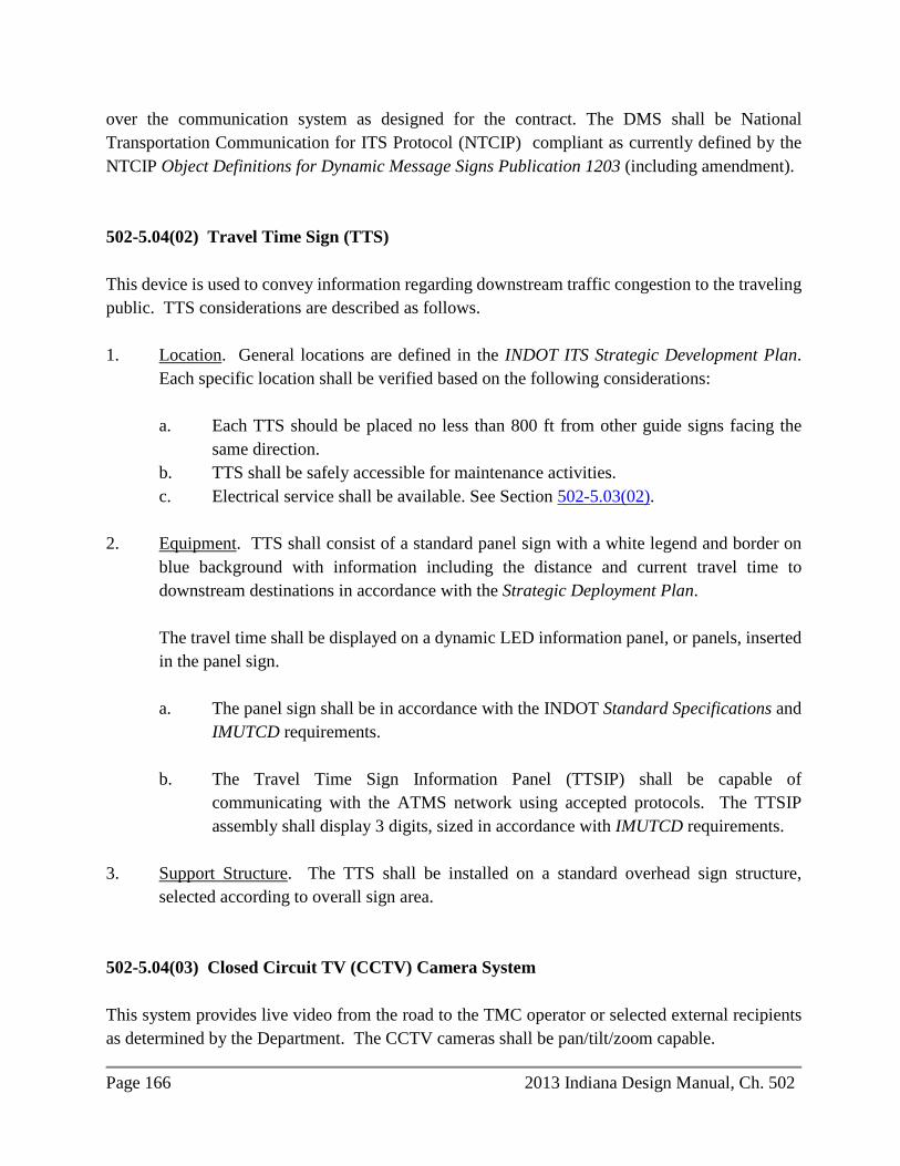
Page 166 2013 Indiana Design Manual, Ch. 502
over the communication system as designed for the contract. The DMS shall be National Transportation Communication for ITS Protocol (NTCIP) compliant as currently defined by the NTCIP Object Definitions for Dynamic Message Signs Publication 1203 (including amendment). 502-5.04(02) Travel Time Sign (TTS) This device is used to convey information regarding downstream traffic congestion to the traveling public. TTS considerations are described as follows. 1. Location. General locations are defined in the INDOT ITS Strategic Development Plan.
Each specific location shall be verified based on the following considerations:
a. Each TTS should be placed no less than 800 ft from other guide signs facing the same direction.
b. TTS shall be safely accessible for maintenance activities. c. Electrical service shall be available. See Section 502-5.03(02).
2. Equipment. TTS shall consist of a standard panel sign with a white legend and border on
blue background with information including the distance and current travel time to downstream destinations in accordance with the Strategic Deployment Plan.
The travel time shall be displayed on a dynamic LED information panel, or panels, inserted in the panel sign.
a. The panel sign shall be in accordance with the INDOT Standard Specifications and
IMUTCD requirements.
b. The Travel Time Sign Information Panel (TTSIP) shall be capable of communicating with the ATMS network using accepted protocols. The TTSIP assembly shall display 3 digits, sized in accordance with IMUTCD requirements.
3. Support Structure. The TTS shall be installed on a standard overhead sign structure,
selected according to overall sign area. 502-5.04(03) Closed Circuit TV (CCTV) Camera System This system provides live video from the road to the TMC operator or selected external recipients as determined by the Department. The CCTV cameras shall be pan/tilt/zoom capable.

2013 Indiana Design Manual, Ch. 502 Page 167
An operator receives real-time video streams and manages control of the camera views. Videos are used to monitor and analyze roadway incidents and to facilitate Hoosier Helper, emergency, and hazardous-material vehicle deployment when necessary. Media outlets have access to delayed video streams, but they do not have control over the cameras. CCTV system specifics are described below. 1. Location. The designer shall verify specific locations given the following considerations.
a. Each camera shall provide a clear overview of the longest possible segment of roadway. Locations shall be identified where more than one camera is needed at a tower site to provide necessary functionality.
b. Each CCTV site shall be safely accessible for maintenance. c. Electrical service shall be available. See Section 502-5.03(02). d. The distance between the CCTV tower site and overhead electrical lines shall be
greater than the height of the support structure, with a preferred distance of more than 150 ft.
2. Camera and Interface Equipment. This consists of the central camera unit, weatherproof
protective housing with clear lens on the bottom, interface unit, and composite power-plus-data-transmittal cable. A composite cable shall be of a length to allow for installation between devices without exceeding the minimum bend radius specified by the manufacturer.
3. Camera Lowering System (CLS). The camera lowering system shall include a permanent
winch with handle and a 1-in. socket. The CLS shall include, where plausible, a guide wire to direct the camera while it is being lowered. This wire shall be secured to the bottom of the tower leg, while the CLS is not in use. The CLS shall provide for the guide wire to be positioned at the appropriate angle to the tower leg while the CLS is in the working position. See Figure 502-5B.
4. Support Structure. A self-supporting tower should be used as the support structure. See
Section 502-5.03(04). A high-mast tower, light pole, or existing cellular communication tower may be used when:
a. one of the structures exists and is available for use in the vicinity of the selected
location; and b. it is unsuitable to build an additional tower at the selected location.

Page 168 2013 Indiana Design Manual, Ch. 502
502-5.04(04) Detection The detection systems should be either non-invasive inductive or side-fire microwave. Detectors shall be located to detect traffic volume and vehicle speeds on the lanes of a multi-lane highway and on the on-ramps at a system (freeway-to-freeway) interchange. The two detection alternatives are described below. 1. Non-Invasive Detector. Two detectors per lane shall be spaced at 20 ft to register the time
between vehicle entry and exit from the detection site, thus defining vehicle speed. This configuration provides both volume and speed data. See Figure 502-5C.
a. Location. Each specific location shall be verified based on the following
considerations:
1) Consistent Traffic Flow. A detector site shall not be placed where vehicles are frequently changing lanes.
2) Control Cabinet Accessibility. A detector site shall be placed such that safe
access to the control cabinet and detector probes is provided for site maintenance.
3) Electrical Service Availability. See Section 502-5.03(02).
b. Equipment. Non-invasive inductive probes, carriers, installation kit, vehicle
detectors, and home-run cables shall be provided at each site.
This type of detection should be used where ITS equipment is being installed in conjunction with a road project involving major multi-lane roadway reconstruction or new pavement construction. Where the existing roadway is being utilized, installation of non-invasive inductive detectors becomes cost prohibitive. An alternative detection method should be considered.
c. Installation. The non-invasive probes shall be installed in PVC conduit having 3-in.
diameter installed 18 to 24 in. below the road surface. The conduits shall be encased in a 12 in. x 12 in. concrete box extending the length of the conduit. Prior to encasement, the conduit shall be placed on PVC spacers of diameter 4 in., spaced at 12 in. apart.

2013 Indiana Design Manual, Ch. 502 Page 169
2. Side-Fire Microwave Detector. Each site provides vehicle speed and volume data from the detector units, mounted above and adjacent to the roadway. Each detector unit can obtain data from 4 to 10 lanes of traffic.
a. Location. Each specific location shall be verified based on the following
considerations:
1) Traffic flow is consistent. Vehicles do not change lanes often. 2) Control cabinet and detector shall be safely accessible for maintenance. 3) For electrical service availability see Section 502-5.03(02). A solar-powered
station shall be used where AC power is cost prohibitive, and where power consumption of the equipment required for the complete functionality does not exceed 100 W.
4) Pole-mounted detector assemblies shall be located outside the clear zone or
in areas protected by guardrail. Refer to cross section sheets for site-specific detector assembly setback distance and mounting height, as well as cross slopes. If recommended height cannot be used due to pole height, detector unit shall be mounted as high as possible within the range recommended by the manufacturer.
b. Equipment. A detection unit, which includes a sequence generator/receiver, an RS
232 or RS 485 based communication device, and a power supply with surge protection shall be provided at each site.
c. Installation. A microwave detector shall be installed adjacent to the roadway
shoulder attached to an existing traffic or ITS structure where possible. If no existing structure is available, the microwave detector shall be installed on a new traffic or ITS structure as directed. The distance from the detector to the control cabinet, or communication cable length shall not exceed the manufacturer’s recommendations.
d. Solar-Powered Site. A stand-alone site may be powered via solar panels if it is too
expensive or infeasible to connect to an AC power source. Solar power components shall be selected such that the system shall be functional under no-sun conditions continuously for 5 days.

Page 170 2013 Indiana Design Manual, Ch. 502
A solar-powered microwave detection site includes the solar panels, batteries, and charging system. Single pole and split design solar-powered detector site configurations are shown on Figure 502-5D. Solar panels shall be opened 186 degrees from magnetic north and shall be tilted 60 degrees from the horizon.
502-5.04(05) Field Controller The field controller, or Aries Field Processor (AFP), is an interfacing device for sensors and communications equipment installed in the cabinet which performs as a terminal server for these devices. Additional options allow the field controller to perform other functions such as video encoding, audio playback for HAR functionality, and field processing of detector data. The designer shall select the appropriate field controller from the Programmatic Proprietary Material Approvals for ITS at http://www.in.gov/indot/2684.htm 502-5.04(06) Communication The purpose of the communication network is to provide stable unrestricted data flow between detection sites, main databases, and information distribution devices, e.g., DMS, TTS, HAR, and video monitors. Licensed or unlicensed wireless, fiber optic, or hybrid communication systems, should be used and configured depending on the following local conditions: 1. line of sight availability; 2. distance between communicating components; 3. existing communications infrastructure components or project funding; and 4. bandwidth requirements. The means of communication are described as follows: 1. Fiber Optic. Communication via fiber-optic cable is the most reliable, the most stable, and
provides the greatest bandwidth capacity. A fiber-optic system consists of the following:
a. Cable. Cable may be standard or armored and shall contain fiberglass strands, or fibers in increments of 12. One communication channel requires two fibers. Four fibers per channel are required if redundancy is specified. Connecting remote sites to the main communication network should be accomplished by means of providing

2013 Indiana Design Manual, Ch. 502 Page 171
dedicated fibers for each channel and connecting each remote site to the nearest CDP. Cable size is dependent on the number of remote sites on each fiber optic subnetwork. Armored cable shall be provided for all direct-buried cable applications.
b. Patch Cable. This is required to interface between the mainline fiber-optic cable and
field/core devices in the cabinet or shelter. The proper wavelength and termination means shall be selected and shown on the plans.
c. Gigabit Interface Converter (GBIC). This is required at both ends of each active
strand in order to convert electronic pulses into pulses of light, amplify them, and at the other end, convert pulses of light back to the electronic series. Depending on the model, GBIC provides ability to cover various distances between end points.
d. Installation. Appropriate means are as follows:
1) Fiber-optic cable should be placed in conduit.
2) Fiber-optic cable shall be installed beneath the outside shoulder or median.
If installed beneath the outside shoulder, the cable shall be placed as far from the edge of the road as possible. Where cable is to be installed beneath the median, the FHWA shall be contacted for approval.
3) Fiber-optic cable post installation shall be located with conductive pull-tape,
copper wire, cable armor, marking tape, or other industry-accepted method.
4) Spare conduits shall be provided for future system expansion.
5) Cable route marking shall be identified with cable duct markers, above-ground cable markers, or other industry-accepted method
e. Networking. Each new component or group of components shall be organized to allow accommodation of the new components into the existing network. The appropriate field, field core, or, if required, core switches shall be selected. The designer shall select the appropriate switches from the Programmatic Proprietary Material Approvals for ITS at http://www.in.gov/indot/2684.htm. Field switches shall be capable of handling multiple multi-cast data streams where required, preventing hardware overload or flooding. The Department will provide a schedule of IP addresses. The naming convention shall be provided for all new components in accordance with Department requirements.

Page 172 2013 Indiana Design Manual, Ch. 502
2. Wireless. This method of communication shall be used if fiber optic is not available, or to complement fiber for data transfer only. A wireless application is possible where there are no obstructions to the line of sight between the ends of the link, and the recommended hardware is capable of producing a signal strong enough to be received by each end of the proposed link. Wireless hardware that is compatible with existing network equipment shall be selected.
A frequency band in compliance with FCC requirements shall be selected. New hardware shall be determined to be compatible with existing. The 5.4 - 5.8 GHz band is utilized. Depending on bandwidth capability, wireless devices are classified as High Speed, approximately 50 Mbps and higher throughput, or Low Speed, 10 to 40 Mbps throughput, used as follows:
a. High Speed Radio is used to connect video streams with one or more sources to
back-bone nodes.
b. Low Speed Radio is used to connect vehicle detection sites to the camera towers and to receive information for the DMSs, TTSs, and HARs.
3. Hybrid. This method of communication combines the fiber-optic and wireless systems
described above. CCTV sites, or cluster hubs, are connected with fiber-optic cable to create a local back-bone structure. Individual vehicle detection sites, DMSs, TTSs, HARs, and Traffic Monitoring Systems located in proximity to a cluster hub communicate wirelessly to the High Speed Radio base unit located at the hub.
502-5.04(07) ITS Handhole and Conduit With the exception of providing a splice location for fiber optic cables where a 4 ft x 6 ft concrete polymer handhole should be specified, all ITS Handholes should be type I (concrete) as shown in the Standard Drawings for traffic signals. The designer should note on the plans that an “ITS” label will be provided on the cover rather than “SIGNAL”. Handholes should not be located in the traveled way or shoulder. Unless otherwise directed herein or by the ITS Deployment Office the designer should specify HDPE conduit for underground applications and steel for above ground. The pay item description should indicate the material type.

2013 Indiana Design Manual, Ch. 502 Page 173
502-5.04(08) Closed Circuit TV Site Requirements 1. Fencing. Where possible, a fence of 15 x 15 ft shall be constructed around the CCTV tower
site. The site fence height shall be 8 ft and shall include a swing gate having width 5 ft. 2. Site Paving. At a fenced CCTV tower site, the interior of the fenced area shall be paved
with non-reinforced portland cement concrete (PCC) of 6 in. depth. A geotextile layer shall be provided for weed control. At a CCTV tower site without a fence, a non-reinforced PCC standing pad, 3 ft x 4 ft x 6 in. depth, attached to the foundation shall be provided beneath the cabinet. The decision to pave the site will be made on an individual site basis.
3. Driveway. A driveway shall be required under the following conditions:
a. parking on the shoulder is not safe; b. site components are located more than 50 ft from the edge of the road or existing
parking area; or c. the drainage ditch is deeper than 4 ft and is located between the shoulder and the
site.
The decision to provide a driveway will be made on an individual site basis. 502-5.04(09) Traffic Monitoring System A traffic monitoring system consists of a Weigh-in-Motion (WIM) sensor, Automatic Traffic Recorder (ATR), Data Collection Site (DCS), or Virtual Weigh-in-Motion (VWIM) station. The Code of Federal Requirements (23 CFR 500 Part B), available at http://ecfr.gpoaccess.gov/23CFR500, establishes a systematic process for the collection, analysis, summary, and retention of highway vehicular traffic data for a traffic monitoring system. To comply with Federal requirements, VWIM, WIM, ATR, and DCS stations exist throughout the state. WIM and VWIM stations are also utilized as vehicle weight screening stations for police enforcement activities. The Virtual Weigh Station Committee should be contacted to determine if a traffic monitoring station is required. See Figure 502-5E. Once the need for construction of a new station or rebuilding an existing station is established, the ITS Technology Deployment Division shall be contacted to coordinate the design and review

Page 174 2013 Indiana Design Manual, Ch. 502
process. See the INDOT Standard Drawings for controller cabinet foundation details. Final layout drawings shall be developed for review by the ITS Technology Deployment Division. VWIM and WIM design criteria are described as follows. 1. Physical Station Requirements. The designer shall coordinate with the Department to
determine where the station may be built within the project limits. The location shall be in accordance with the following.
a. Horizontal Alignment. The horizontal curvature of the roadway for 200 ft in
advance of and 100 ft beyond the system sensors shall have a radius of not less than 5700 ft measured along the centerline of the roadway.
b. Vertical Alignment. The grade of the roadway surface for 200 ft in advance of and
100 ft beyond of the sensors is not to be steeper than 2%.
c. Cross Slope. The cross slope of the roadway surface for 200 ft in advance of and 100 ft beyond the sensors preferably should not be steeper than 3%. However, up to 4% is acceptable, but a grade steeper than 2% is allowable only in the leftmost travel lanes.
d. Lane Width. Stations shall not be placed where the lane width is less than 11.5 ft or
greater than 14 ft. 2. Pavement. Adequate pavement structure and surface smoothness to accommodate weigh
sensors throughout their service life shall be required to ensure optimum performance of the system. PCCP should be used. If on a freeway or principal arterial highway, the station shall be centered within a 450-ft segment of concrete pavement.
a. Reinforced PCCP for Sensor Panels. Reinforced pavement panels are required
where roadway sensors are to be placed. The reinforcing bars shall be placed in the lower half of the depth of pavement to minimize interference with loop detectors. In jointed PCCP where transverse joints are spaced at 18 ft, the reinforced PCCP section is within the center 50 ft of the 450-ft PCCP section.
b. Pavement Smoothness. The surface of the roadway a minimum of 200 ft in advance
of and 100 ft beyond the system sensors shall be tested prior to sensor installation. The designer shall specify that the contractor use ASTM E 1318 Section 6.1.5.1 as the basis for testing.

2013 Indiana Design Manual, Ch. 502 Page 175
3. Electronic Equipment.
a. System Controller. A system controller is used with each Type I or Type II WIM system. The Department shall determine which type of system is to be specified, including the appropriate sensor array. A controller shall operate from 120 VAC, be accessible via IP-based communication systems, provide on-site data storage, and interface to roadway sensor arrays described in item 4.f below.
b. Field Controller. An AFP is required. See Section 502-5.04(05).
c. Router. A router with VPN and firewall shall be used to provide interconnection of system components at the station to the existing network. See 502-5.04(09).5b.
d. VWIM Imaging System. The purpose of the VWIM imaging system is to provide
images of vehicles passing over the sensors so that they can be linked to the data record. These images shall be able to be viewed in real time or stored for future use. Each VWIM imaging system consists of the following components:
1) camera, lens, and weatherproof enclosure; 2) pole and foundation. See the INDOT Standard Specifications and Standard
Drawings; and 3) illuminator system, infrared for night vision. The angle between the line of the camera axis and the line perpendicular to the direction of the traffic shall be 30 degrees.
4. Station Components. See Figure 502-5F for a four-lane divided highway VWIM overview.
Each station shall include the following components:
a. Cabinet. The cabinet shall be in accordance with Section 502-5.03(03) and the INDOT Standard Drawings.
b. Cabinet Foundation. The cabinet foundation shall be in accordance with the INDOT
Standard Drawings.
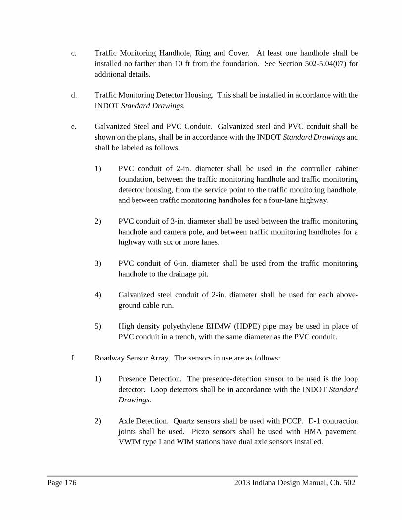
Page 176 2013 Indiana Design Manual, Ch. 502
c. Traffic Monitoring Handhole, Ring and Cover. At least one handhole shall be installed no farther than 10 ft from the foundation. See Section 502-5.04(07) for additional details.
d. Traffic Monitoring Detector Housing. This shall be installed in accordance with the
INDOT Standard Drawings.
e. Galvanized Steel and PVC Conduit. Galvanized steel and PVC conduit shall be shown on the plans, shall be in accordance with the INDOT Standard Drawings and shall be labeled as follows:
1) PVC conduit of 2-in. diameter shall be used in the controller cabinet
foundation, between the traffic monitoring handhole and traffic monitoring detector housing, from the service point to the traffic monitoring handhole, and between traffic monitoring handholes for a four-lane highway.
2) PVC conduit of 3-in. diameter shall be used between the traffic monitoring
handhole and camera pole, and between traffic monitoring handholes for a highway with six or more lanes.
3) PVC conduit of 6-in. diameter shall be used from the traffic monitoring
handhole to the drainage pit.
4) Galvanized steel conduit of 2-in. diameter shall be used for each above-ground cable run.
5) High density polyethylene EHMW (HDPE) pipe may be used in place of
PVC conduit in a trench, with the same diameter as the PVC conduit.
f. Roadway Sensor Array. The sensors in use are as follows:
1) Presence Detection. The presence-detection sensor to be used is the loop detector. Loop detectors shall be in accordance with the INDOT Standard Drawings.
2) Axle Detection. Quartz sensors shall be used with PCCP. D-1 contraction
joints shall be used. Piezo sensors shall be used with HMA pavement. VWIM type I and WIM stations have dual axle sensors installed.

2013 Indiana Design Manual, Ch. 502 Page 177
3) Temperature Sensor. One temperature sensor is required for each controller and shall be in accordance with controller manufacturer recommendations.
Sensor placement should be such that saw slots are no closer than 2 ft to transverse pavement joints. Sensors shall be offset from the leftmost lane to the right approximately 6.75 ft in a downstream direction. The designer shall coordinate details with the ITS Technology Deployment Division.
5. Utilities and Communication.
a. Utilities. Stations shall have electrical service points in accordance with Section 502-5.03(02).
b. Communication. Stations shall have a high-speed peripheral communication point.
The methods of communication listed in order of preference are as follows:
1) connection to the Department’s communication network described in Section 502-5.04(06);
2) high-speed digital subscriber line (DSL) internet service; or 3) high-speed wireless cellular broadband service.
502-5.05 Plan Development Procedure 502-5.05(01) Site Reviews 1. Office. The site selection shall be provided to the Department at the following stages:
a. Scoping. At the scoping meeting, the Department and the designer shall discuss general requirements for the upcoming project, including coordination with existing Department ITS infrastructure.
b. Preliminary. At this meeting, preliminary site selection shall be discussed, based on
the recommendations of the INDOT ITS Strategic Deployment Plan. The designer and the Department shall discuss information including constructability and communication issues for each proposed site and adjust locations if necessary. Each variation from the Strategic Plan, e.g., site additions, site removals, or site enhancements shall be subject to approval by the Department at this meeting.
Page 178 2013 Indiana Design Manual, Ch. 502
c. Mid-Project, or Completion 60%. The designer shall provide preliminary cost estimate and special provisions as well as preliminary plans of the following:
1) site locations; 2) communication information; 3) constructability requirements; 4) driveway or fencing; 5) drainage; 6) grounding; and 7) electrical service connections and utility coordination.
d. Final. One month before the contract RFC date, the designer shall provide the final
design package, which shall include the following:
1) title and index sheets; 2) plans sheets; 3) site details; 4) construction details, e.g. foundations, grounding, driveways, pipes, fences
and gates; 5) cabinet details; 6) electrical and communication schematics; 7) electrical wiring diagrams; 8) quantities; 9) design calculations, e.g. drainage, communications line of sight, driveways,
guardrail, voltage drops; 10) cost estimate; and 11) special provisions.
2. Field. Field visits will be required throughout the design process to verify the design
parameters and to coordinate with utilities. The designer shall notify the Department of all field activities to enable Department representatives to participate.
502-5.05(02) Bucket Truck Survey During the design process after preliminary site selection and prior to final site selection approval, the designer shall verify the viewing areas of new cameras and the line of sight for the wireless communication. A bucket truck survey may be required if necessary and feasible. The Department may provide equipment and personnel for this survey if available. If the Department and personnel are not available, the designer shall provide equipment and personnel if a survey is warranted.
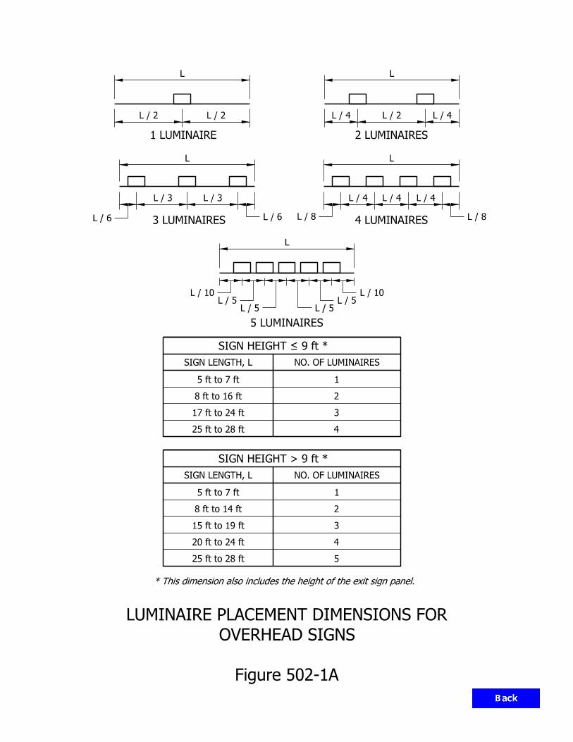
2
1
4
3
5 ft to 7 ft
8 ft to 16 ft
17 ft to 24 ft
25 ft to 28 ft
SIGN LENGTH, L
2
1
4
3
5 ft to 7 ft
8 ft to 14 ft
15 ft to 19 ft
20 ft to 24 ft
SIGN LENGTH, L
25 ft to 28 ft 5
3 LUMINAIRES
1 LUMINAIRE 2 LUMINAIRES
4 LUMINAIRES
5 LUMINAIRES
SIGN HEIGHT = 9 ft *
SIGN HEIGHT > 9 ft *
Figure 502-1A
OVERHEAD SIGNS
LUMINAIRE PLACEMENT DIMENSIONS FOR
LL
LL
L
L / 6
L / 3L / 3
L / 6 L / 8
L / 4L / 4L / 4
L / 8
L / 4L / 2L / 4L / 2L / 2
L / 10L / 5
L / 5L / 5L / 5
L / 10
NO. OF LUMINAIRES
NO. OF LUMINAIRES
* This dimension also includes the height of the exit sign panel.

Figure 502-1B
SIGN GORE TREATMENT
20 ft
*
*
Ramp
Mainline
* 6 ft plus shoulder width or 12 ft, whichever is greater
E.T.L.
Assembly
Gore Sign
Treatment
Asphalt Gore
Edge of Shoulder
A
A
4 ft shoulder
3 ft or
gore treatment
outside asphalt
Sign to be centered
W
H
7 ft
20 in.
5’ 0"
(42 in. x 30 in.)
E.T.L.
R5-1a
W/5 3W/5W/5
Gore Sign
Back of Exit
breakaway posts)
(Use 2-W6 x 9
SECTION A-A
WAY
WRONG

Truss Type Max. Sign Area (Sq. Ft). Span (Ft.). Maximum Mounting Height A 500 130
28’ 6” B
700 100
C 130 D
900 100
E 130
SIGN BOX TRUSS STRUCTURE SELECTION GUIDANCE
Figure 502-1C(1)

Str. Type Max. Span (ft) Max. Sign Area
(Sq. Ft.) Maximum Mounting
Height A 10 180
24’ 0”
B 15 280 C 20 380 D 25
300 E 30 F 35 G 25
400 H 30 I 35
• Type A, B, C are Double Arm Cantilever Structures • Type D, E, F, G, H, I are quadric-Chord Cantilever Structures
SIGN CANTILEVER STRUCTURE SELECTION GUIDANCE
Figure 502-1C(2)
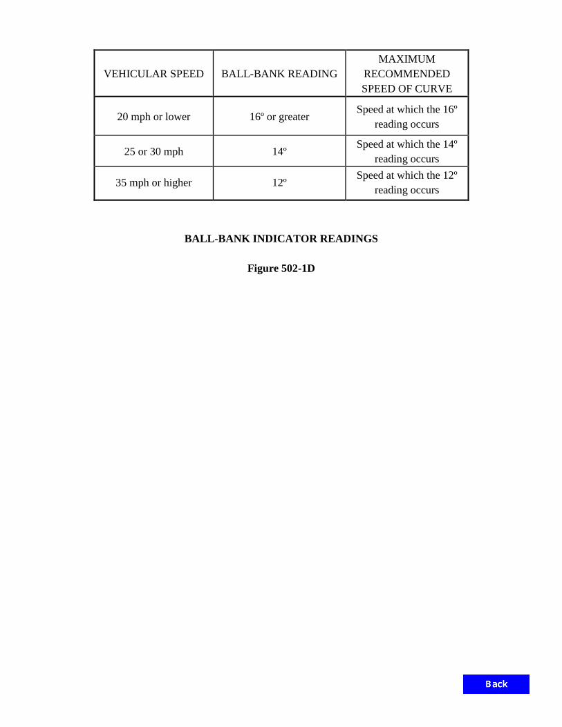
VEHICULAR SPEED BALL-BANK READING MAXIMUM
RECOMMENDED SPEED OF CURVE
20 mph or lower 16º or greater Speed at which the 16º
reading occurs
25 or 30 mph 14º Speed at which the 14º
reading occurs
35 mph or higher 12º Speed at which the 12º
reading occurs
BALL-BANK INDICATOR READINGS
Figure 502-1D

SIGN SOFTWARE INPUT AND SPACING REQUIREMENTS
Figure 502-1E
SIGN LETTER SIZE 20”-15” 16”-12” 13.3”-10” 8”-6” 12”
8” UC 6”-
4” BORDER
RADIUS 9” 9” 9” 9” 9” 9” 2” BORDER 2” 2” 2” 2” 2” 2” 1” SUBPANELS NONE NONE NONE NONE NONE NONE NONE PANEL SIZE 12” 12” 12” 12” 12” 12” 6” SIGN CLEARANCE LEFT 20” 16” 13” 8” 12” 8” 6” RIGHT 20” 16” 13” 8” 12” 8” 6” ROUND X 12” 12” 12” 12” 12” 12” 6” TOP 9” 9” 9” 9” 9” 9” 6” BOTTOM 9” 9” 9” 9” 9” 9” 6” ROUND Y 12” 12” 12” 12” 12” 12” 6” EXIT PANEL, EXIT PANEL HEIGHT SHALL BE 36”
LEFT 10” 10” 10” RIGHT 10” 10” 10” ROUND X 6” 6” 6” TOP 10” 10” 10” BOTTOM 10” 10” 10” ROUND Y 12” 12” 12” SPACING BETWEEN ADJACENT LINES FONT E(M) E(M) E(M) E(M) E(M) E(M) D C LETTER HEIGHT ROW 1 20” 16” 13” 8” 12” 8” 6” 4” LETTER HEIGHT ROW 2 20” 16” 13” 8” 12” 8” 6” 4” SPACING 15” 12” 10” 6” 9” 6” 4” 3” ARROW WIDTH DOWN 32” x 22” 32” x 22” 32” x 22” ---- ---- ---- ---- ---- DIRECTIONAL 22” x 35” 22” x 35” 18” x 28” ---- ----
INTERSTATE GORE SIGN NON-INTERSTATE GORE LEFT 12” 6”
RIGHT 12” 6” TOP 9” 6” BOTTOM 9” 6” TEXT SIZE, letters or numeral 12”/18” 10” ROUTE SHIELD SIZE --- 24” ARROW SIZE 13.5” x 28” 15” x 18” SINGLE SPACE REQUIRED BETWEEN NUMERAL AND ALPHA i.e., EXIT 99 B 6” SPACING REQUIRED BETWEEN EXIT NUMBER AND ARROW “EXIT ONLY” PANEL SHOULD BE 36” HEIGHT SPACE BETWEEN SHIELD AND FIRST LINE SHOULD BE 15” SPACE BETWEEN SHIELD AND CARDINAL DIRECTION SHOULD BE 12”, AND SHALL BE TOP ALIGNED FOR DIAGRAMMATIC SIGN,THE SPACE BETWEEN ARROW AND SHIELD OR WORD SHOULD BE 12” FOR D1 OR D2 SIGN, SPACE BETWEEN WORD, NUMERAL AND ARROW IN A LINE SHOULD BE 6” PANEL SIGN SIZE SHALL BE TO THE NEAREST 1FT. INCREMENT

LETTER SIZE (UPPER CASE)
DIMENSIONS A B C D E R
8” 15 1/8” 11 9/16” 3 ¾” 1 5/16” 17”- 25” 13/16” 10”- 13 1/3” 18 ¼” 14” 4 ½” 1 ½’ 20”- 30” ¾”
16”- 20” 22 ¼” 17” 5 3/8” 1 ¾” 25”- 35” 1”
NOTE: For arrows with a tail, use standard arrow with 1’ extension.
ARROW DIMENSIONS
Figure 502-1F

1
1
2
2
to ramp geometry
Arrow angle should conform
Install at 1/2 mile distance
Ground-Mounted (Panel Sign)
Overhead Signs (Box Truss)
Overhead Sign (Cantilever)
LEGEND:
Freeway
Divided Hig
hway
DIAMOND INTERCHANGE SIGNING
Divided Highway over Freeway
Figure 502-1G

1
2
2
1
Freeway
Divided Hig
hway
to ramp geometry
Arrow angle should conform
Install at 1/2 mile distance
Ground-Mounted (Panel Sign)
Overhead Sign (Cantilever)
LEGEND:
DIAMOND INTERCHANGE SIGNING
Divided Highway under Freeway
Figure 502-1H

300’
300’
Freeway
Undivided Hig
hway
-Mounted (Panel Sign)Ground
Ground-Mounted (Sheet Sign)
Overhead Sign (Cantilever)
LEGEND:
DIAMOND INTERCHANGE SIGNING
Undivided Highway over Freeway
Figure 502-1 I

DIAMOND INTERCHANGE SIGNING
Undivided Highway under Freeway
Figure 502-1J
300’
300’
Freeway
Undivided Hig
hway
Mounted (Panel Sign)Ground-
Ground-Mounted (Sheet Sign)
Overhead Sign (Cantilever)
LEGEND:

FULL CLOVERLEAF INTERCHANGE SIGNING
Divided Highway over Freeway
Figure 502-1K
Freeway
Divided Hig
hway
(Panel Sign)Ground-Mounted
Overhead Signs (Box Truss)
Overhead Sign (Cantilever)
LEGEND:

1
Freeway
Divided Hig
hway
Ground-Mounted (Panel Sign)
Ground-Mounted (Sheet Sign)
Overhead Signs (Box Truss)
Overhead Sign (Cantilever)
LEGEND:
FULL CLOVERLEAF INTERCHANGE SIGNING
Divided Highway under Freeway
Figure 502-1L
of bridge use this "Arrow with tail"
If exit lane is not full width upstream1
or

FULL CLOVERLEAF INTERCHANGE SIGNING
Undivided Highway over Freeway
Figure 502-1M
Undivided Hig
hway
Freeway
Ground-Mounted (Panel Sign)
Overhead Signs (Box Truss)
Overhead Sign (Cantilever)
LEGEND:

or
Undivided Hig
hway
Freeway
Ground-Mounted (Panel Sign)
Ground-Mounted (Sheet Sign)
Overhead Signs (Box Truss)
Overhead Sign (Cantilever)
LEGEND:
FULL CLOVERLEAF INTERCHANGE SIGNING
Undivided Highway under Freeway
Figure 502-1N
1
of bridge use this "Arrow with tail".
If exit lane is not full width upstream1

1
(See Figure 502-1P for opposite direction of travel.)
Freeway
Divided Hig
hway
Install at 1/2 mile distance.
Ground-Mounted (Panel Sign)
Ground-Mounted (Sheet Sign)
Overhead Signs (Box Truss)
Overhead Sign (Cantilever)
LEGEND:
1
2
2
to ramp geometry.
Arrow angle should conform
PARTIAL CLOVERLEAF INTERCHANGE SIGNING
Divided Highway over Freeway
Figure 502-1 O

1
(R or L)
W13-3a
(R or L)
W13-3a
(See Figure 502-1 O for opposite direction of travel.)
1
Freeway
Divided Hig
hway
Install at 1/2 mile distance.
Ground-Mounted (Panel Sign)
Ground-Mounted (Sheet Sign)
Overhead Signs (Box Truss)
Overhead Sign (Cantilever)
LEGEND:
PARTIAL CLOVERLEAF INTERCHANGE SIGNING
Divided Highway over Freeway
Figure 502-1P

(See Figure 502-1R for opposite direction of travel.)
1
1
Divided Hig
hway
Freeway
Ground-Mounted (Panel Sign)
Ground-Mounted (Sheet Sign)
Overhead Sign (Cantilever)
LEGEND:
to ramp geometry.
Arrow angle should conform
PARTIAL CLOVERLEAF INTERCHANGE SIGNING
Divided Highway under Freeway
Figure 502-1Q
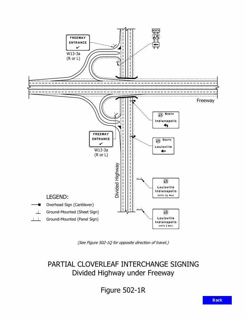
(R or L)
W13-3a
(R or L)
W13-3a
Divided Hig
hway
Freeway
Ground-Mounted (Panel Sign)
Ground-Mounted (Sheet Sign)
Overhead Sign (Cantilever)
LEGEND:
(See Figure 502-1Q for opposite direction of travel.)
PARTIAL CLOVERLEAF INTERCHANGE SIGNING
Divided Highway under Freeway
Figure 502-1R
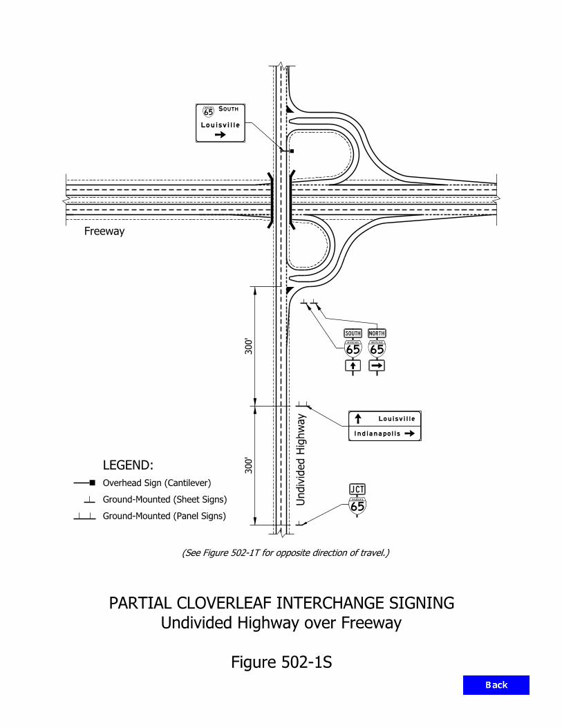
(See Figure 502-1T for opposite direction of travel.)
300’
300’
Freeway
Undivided Hig
hway
PARTIAL CLOVERLEAF INTERCHANGE SIGNING
Undivided Highway over Freeway
Figure 502-1S
Ground-Mounted (Panel Signs)
Ground-Mounted (Sheet Signs)
Overhead Sign (Cantilever)
LEGEND:

Freeway
Undivided Hig
hway
(R or L)
W13-3a
(R or L)
W13-3a
PARTIAL CLOVERLEAF INTERCHANGE SIGNING
Undivided Highway over Freeway
Figure 502-1T
(See Figure 502-1S for opposite direction of travel.)
300’
300’
Ground-Mounted (Panel Signs)
Ground-Mounted (Sheet Signs)
Overhead Sign (Cantilever)
LEGEND:

(See Figure 502-1T for opposite direction of travel.)
Undivided Hig
hway
Freeway
Ground-Mounted (Panel Sign)
Ground-Mounted (Sheet Sign)
Overhead Sign (Cantilever)
LEGEND:
PARTIAL CLOVERLEAF INTERCHANGE SIGNING
Undivided Highway under Freeway
Figure 502-1U
300’
300’

(R or L)
W13-3a
(R or L)
W13-3a
(See Figure 502-1U for opposite direction of travel.)
Undivided Hig
hway
Freeway
Ground-Mounted (Panel Sign)
Ground-Mounted (Sheet Sign)
Overhead Sign (Cantilever)
LEGEND:
PARTIAL CLOVERLEAF INTERCHANGE SIGNING
Undivided Highway under Freeway
Figure 502-1V
300’
300’

Freeway
Divided Hig
hway
(Panel Signs)
Ground-Mounted
(Box Truss)
Overhead Signs
LEGEND:
TRUMPET INTERCHANGE SIGNING
System Interchange
Figure 502-1W

ROUTE MARKER ASSEMBLY POST DETAILS
Figure 502-1X
2" x 2" x 0.105"
20" 20"
Spacing > 7’-0"
36"
2 1/2" x 2 1/2" x 0.105"
Unreinforced
3" x 3" x 0.1793"
other pay items)
(To be included with
Aluminum Bar Bracing
1 3/4" x 1 3/4" x 0.075"
other pay items)
(To be included with
Aluminum Bar Bracing
1 3/4" x 1 3/4" x 0.075"
Unreinforced Anchor Base
Reinforced Anchor or
2 1/4" x 2 1/4" x 0.105"
2 SHIELDS ASSEMBLY 3 SHIELDS ASSEMBLY
for details.
Drawing E802-SNGS-10
Refer to Standard
24"
15"
24"
14"
2"
2"
6"
21"
21"
24"
12"
24"
15"
5"
5"
series and posts.
The detail above is for 24" RMA NOTE:

orRMAIGD
R8-Y9
R2-Y2
any/or
R2-1 (XX)
End of
Taper
R4-Y10 (>2-Lane)
or
R4-Y9 (2-Lane)
500’500’500’500’500’
POST-INTERCHANGE SEQUENCE SIGNS
FOR INTERSTATE FREEWAY
Figure 502-1Y
(Page 1 of 2)
TR
UC
KS
OVER
13 TO
NDECLA
RED
GR.
WT.
M.
P.
H.
XX
NO
STOPPING
STANDING
OR
PARKING

RMA
(optional)
IGD
R2-1 (XX)
POST-INTERCHANGE SEQUENCE SIGNS
FOR NON-INTERSTATE FREEWAY OR EXPRESSWAY
FIGURE 502-1Y
(Page 2 of 2)
End of
Taper
500’500’500’
W estfield 7
Kokom o 32
South Bend 12031

St. Louis, Louisville
I - 65 Louisville, Indianapolis, Chicago
Indianapolis, Fort Wayne, LansingI - 69
I - 70
I - 74 Peoria, Indianapolis, Cincinnati
I - 90
Chicago, Detroit
NATIONAL CONTROL CITIESROUTE
I - 65
I - 69
I - 70
I - 74
I - 90
REGIONAL CONTROL CITIESROUTE
Evansville
Lafayette, Columbus, Gary
Anderson, Angola
Terre Haute, Richmond
Crawfordsville, Shelbyville
I - 94
Lafayette, Fort Wayne
I - 94 Gary, Michigan City
US - 20
US - 24
US - 30
US - 31
US - 40
US - 52
Gary, South Bend, Elkhart
Valparaiso, Plymouth, Fort Wayne
Terre Haute, Indianapolis, Richmond
Lafayette, Indianapolis, Cincinnati
St. Louis, Indianapolis, Dayton
Chicago, Toledo
Westfield, Kokomo, South Bend
Louisville, Columbus, Indianapolis,
I - 64
I - 64
See Note 2
NOTES:
They should be verified with the appropriate district.
3. Regional control cities for US routes are recommendations.
2. I - 90 regional control cities determined by Indiana Toll Road.
1. I - 80 follows same alignment as I - 90 or I - 94.
NATIONAL AND REGIONAL CONTROL CITIES
FOR INTERSTATE AND MAJOR U.S. ROUTES
Figure 502-1 Z
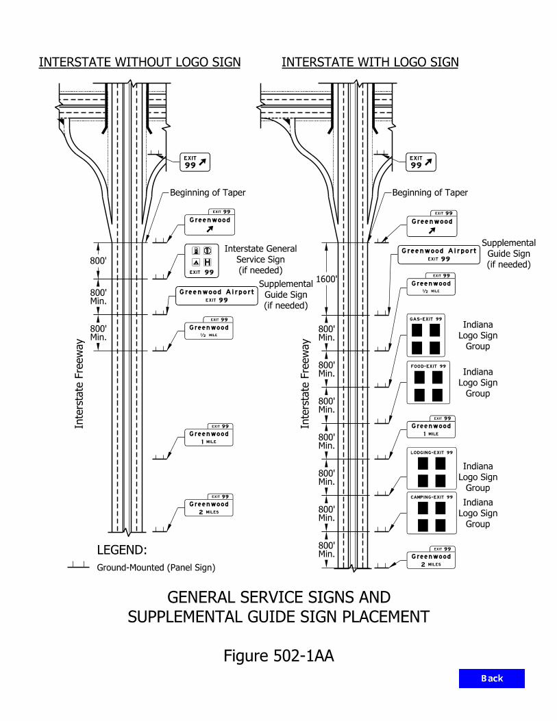
Ground-Mounted (Panel Sign)
LEGEND:
(if needed)
Guide Sign
Supplemental
(if needed)
Guide Sign
Supplemental
GENERAL SERVICE SIGNS AND
SUPPLEMENTAL GUIDE SIGN PLACEMENT
Figure 502-1AA
Beginning of Taper
Min.800’
Min.800’
800’
Interstate Fre
eway
Interstate Fre
eway
Beginning of Taper
1600’
Min.800’
Min.800’
Min.800’
Min.800’
Min.800’
Min.800’
Min.800’
INTERSTATE WITHOUT LOGO SIGN INTERSTATE WITH LOGO SIGN
(if needed)
Service Sign
Interstate General
Group
Logo Sign
Indiana
Group
Logo Sign
Indiana
Group
Logo Sign
Indiana
Group
Logo Sign
Indiana
Greenwood
EXIT 99
Greenwood
‰ MILE
EXIT 99
Greenwood
1 MILE
EXIT 99
Greenwood Airport
EXIT 99
Greenwood
2 MILES
EXIT 99
Greenwood
EXIT 99
Greenwood
‰ MILE
EXIT 99
Greenwood
1 MILE
EXIT 99
Greenwood Airport
EXIT 99
GA S-EXIT 99
LODGING-EXIT 99
Greenwood
2 MILES
EXIT 99
FOOD-EXIT 99
CAMPING-EXIT 99
99ITXE
99
EXIT
99
EXIT
A
H

I-64 Mile 0 to Mile 117: 1/2 Mile Reference Marker Mile 117 to Mile 124: 2/10 Mile Enhanced Reference Markers I-65 Mile 0 to Mile 6: 1/10 Mile Enhanced Reference Markers Mile 6 to Mile 16: 2/10 Mile Enhanced Reference Markers Mile 16 to Mile 86: 1/2 Mile Reference Markers Mile 86 to Mile 99: 2/10 Mile Enhanced Reference Markers Mile 99 to Mile 123: 1/10 Mile Enhanced Reference Markers Mile 123 to Mile 150: 2/10 Mile Enhanced Reference Markers Mile 150 to Mile 235: 1/2 Mile Reference Markers Mile 235 to Mile 253: 2/10 Mile Enhanced Reference Markers Mile 253 to Mile 259: 1/10 Mile Enhanced Reference Markers Mile 259 to Mile 262: 2/10 Mile Enhanced Reference Markers I-69, Evansville to Indianapolis I-64 to 2 miles S of SR 144: 1/2 Mile Reference Markers 2 miles S of SR 144 to Smith Valley Rd: 2/10 Mile Enhanced Reference Markers Smith Valley Rd to I-465: 1/10 Mile Enhanced Reference Markers I-69, Indianapolis to Michigan Mile 0 to Mile 6: 1/10 Mile Enhanced Reference Markers Mile 6 to Mile 29: 2/10 Mile Enhanced Reference Markers Mile 29 to Mile 94: 1/2 Mile Reference Markers Mile 94 to Mile 117: 2/10 Mile Enhanced Reference Markers Mile 117 to Mile 157: 1/2 Mile Reference Markers I-70 Mile 0 to Mile 55: 1/2 Mile Reference Markers Mile 55 to Mile 69: 2/10 Mile Enhanced Reference Markers Mile 69 to Mile 81: 1/10 Mile Enhanced Reference Markers I-70 follows I-65 Mile 82 to Mile 91: 1/10 Mile Enhanced Reference Markers Mile 91 to Mile 107: 2/10 Mile Enhanced Reference Markers Mile 107 to Mile 156: 1/2 Mile Reference Markers
REFERENCE MARKER/ENHANCED REFERENCE MARKER LOCATIONS Figure 502-1BB
(Page 1 of 2)

I-74 Mile 0 to Mile 65: 1/2 Mile Reference Markers Mile 65 to Mile 73: 2/10 Mile Enhanced Reference Markers I-74 follows I-465 Mile 94 to Mile 100: 2/10 Mile Enhanced Reference Markers Mile 100 to Mile 171: 1/2 Mile Reference Markers I-80/94 Mile 0 to Mile 15.5: 1/10 Mile Enhanced Reference Markers I-94 Mile 15.5 to Mile 19: 1/10 Mile Enhanced Reference Markers Mile 19 to Mile 46: 2/10 Mile Enhanced Reference Markers I-164 Mile 0 to Mile 21: 1/2 Mile Reference Markers I-265 Mile 0 to Mile 9: 2/10 Mile Enhanced Reference Markers Mile 9 to Ohio River Bridge: 2/10 Mile Enhanced Reference Markers I-275 Mile 0 to Mile 3: 1/2 Mile Reference Markers I-465 Mile 0 to Mile 53: 1/10 Mile Enhanced Reference Markers I-469 Mile 0 to Mile 31: 2/10 Mile Enhanced Reference Markers I-865 Mile 0 to Mile 5: 2/10 Mile Enhanced Reference Markers US 31 Freeway, Hamilton County I-465 to 216th St: 1/10 Mile Enhanced Reference Markers SR 912 / Cline Avenue Mile 4 to Mile 11: 2/10 Mile Enhanced Reference Markers All other freeways: 1/2 Mile Reference Markers
REFERENCE MARKER/ENHANCED REFERENCE MARKER LOCATIONS Figure 502-1BB
(Page 2 of 2)

(1) No change required to existing sign and supports.
(2) Remove existing panel sign from ground mounted supports.
(3) Remove existing sheet sign from supports.
(4) Remove existing panel sign from overhead sign structure.
(5) Remove existing sheet sign from overhead sign structure.
(6) Remove existing sign foundation.
(7) Remove existing sheet sign and supports.
(8) Remove existing ground mounted panel sign, supports, and foundations.
(9) Remove existing overhead sign, supports, and foundations.
(10) Remove existing sign and bridge bracket assembly.
(11) Existing sheet sign on new supports.
(12) Existing panel sign on new supports.
(13) Existing panel sign on new overhead structure.
(14) New panel sign on existing ground mounted supports.
(15) New panel sign on existing overhead structure.
SIGN PLANS NOTES
Figure 502-1CC

SIGN PLAN LEGEND
Figure 502-1DD
IGDO
IGD
IGS
IGI
GDO
GD
IGDOE
IGDE
IGSE
IGIE
GDOE
GDE
Box Truss, Tri Cord Truss
Monotube Span Structure, Cable Span Structure
Double Mastarm, Single Mastarm Structure
Center-Mounted Structure (Double Mastarm
and Single Mastarm)
Ground-Mounted Panel Sign
Ground-Mounted Sheet Sign
Bridge Bracket Sign Structure
Interstate Guide Directional Overhead Sign
Interstate Guide Directional Sign
Interstate Guide Service and Rest Area Sign
Interstate Guide Information Sign
Guide Directional Overhead Sign
Guide Directional Sign
Interstate Guide Directional Overhead Existing Sign
Interstate Guide Directional Existing Sign
Interstate Guide Service Existing Sign
Interstate Guide Information Existing Sign
Guide Directional Overhead Existing Sign
Guide Directional Existing Sign

Yellow Center Line
4" Double Solid
White Edge Line
8" Solid
Yellow Center Line
with 4" Broken
Yellow Lane Line
4" Solid
White Edge Line
8" Solid
Yellow Center Line
4" Double Solid
White Edge Line
4" Solid
at 20’ Spacing
12" White Line
White Edge Line
4" Solid
White Edge Line
4" Solid
White Dotted Lines
8" Single
White Lane Lines
4" Broken
24" Stop Line
TYPICAL INTERSECTION PAVEMENT MARKINGS
Figure 502-2A
24" Yield Line
24" Yield Line

DESCRIPTION COLOR WIDTH APPLICATION Separation of lanes on which travel is in the same direction, with crossing from one lane to the 4 in. other permitted, e.g., lane lines on a multi-lane roadway. The broken line is formed by a pattern of segments and gaps. The typical pattern is a 10-ft segment followed by a 30-ft White gap for a for a total cycle length of 40 ft. Separation of freeway lanes on which travel is in the same direction, with crossing from one lane to the Single Broken Line 5 in. other permitted. The broken line is formed by a pattern of segments and gaps. The typical pattern is a 10-ft segment followed by a 30-ft gap for a total cycle length of 40 ft. Separation of lanes on which travel is in opposite directions, and where overtaking with care is Yellow 4 in. permitted, e.g. centerline on 2-lane, 2-way roadway. The broken line is formed by a pattern of segments and gaps. The typical pattern is a 10-ft segment followed by a 30-ft gap for a total cycle length of 40 ft. 4 in. Separation of lanes, or of a lane and shoulder, where lane changing is discouraged, e.g., lane lines at an intersection approach, right-edge line. White 6 in. Lane lines separating a motor vehicle lane from a bike lane. Single Solid Line Delineation of location where crossing is discouraged, e.g., separation of turn lane 8 in. from through lane, gore area at ramp terminal, paved turnout, edge line at lane drop, or painted island edges. Yellow 4 in. Delineation of left-edge line on divided highway, 1-way road or ramp. White 4-8-4 in.* Separation of lanes on which travel is in the same direction, with crossing from one side to the other prohibited, e.g., channelization in advance of obstruction which may be passed on either side. Double Solid Lines
4-8-4 in.* Separation of lanes on which travel is in opposite directions, where overtaking is prohibited in
Yellow both directions. A left-turn maneuver across this marking is permitted. Also used in advance of obstruction which may be passed only on the right side.
4-8-4 in.*
Separation of lanes on which travel is in opposite directions, where overtaking is permitted Solid Line Plus Yellow for traffic adjacent to the broken line, but prohibited for traffic adjacent to a solid line. Used Broken Line on a 2-way roadway with 2 or 3 lanes. Also used to delineate edges of a two-way left-turn lane, with solid lines on the outside, broken lines on the inside.
4-8-4 in.* Delineates the edges of reversible lanes. The broken line is formed by a pattern of
Double Broken Line Yellow segments and gaps. The typical pattern is a 10-ft segment followed by a 30-ft gap for a total cycle length of 40 ft.
*4-8-4 in. indicates typical width of the lines and the 8-in. unpainted gap between them
PAVEMENT MARKING LINES APPLICATIONS Figure 502-2B (Page 1 of 2)

DESCRIPTION COLOR WIDTH APPLICATION
Single Dotted Line
4 in.
See Section 502-2.02(05). Color same as that of the line being extended. The typical pattern is a 2-ft
Either
or 3-ft segment with a 9-ft gap for a lane line, or a 2- to 6-ft gap for an extension lines through an
intersection.
5 in. See Section 502-2.02(05). Color same as that of the line being extended. The typical pattern is a
2-ft segment with a 9-ft gap for a lane line or a 2- to 6-ft gap for an extension lines through an
intersection.
8 in.
See Section 502-2.02(05). Separation of through lane and auxiliary lane or dropped lane.
White
The typical pattern is a 3-ft segment followed by a 9-ft gap for a total cycle length of 12 ft.
10 in. See Section 502-2.02(05). Separation of through lane and auxiliary lane or dropped lane.
The typical pattern is a 3-ft segment followed by a 9-ft gap for a total cycle length of 12 ft.
Parallel Crosswalk
Lines White 12 in.
Parallel or zebra crosswalk lines, if used, are as long as the crosswalk width (typically 6 ft) and are offset
from each other by 30 in. The lines should be spaced to avoid wheel paths.
Transverse Lines White 6 in. Crosswalk edge line, minimum 6 ft apart.
24 in. Stop or yield line.
Crosshatch marking for 1-way traffic, placed at an angle of 45o, at 20 ft apart, on a shoulder or
12 in. channelization island to add emphasis to the roadway feature for a speed limit of 40 mph or lower.
White
Crosshatch marking for 1-way traffic, placed at an angle of 45
o, at 40 ft apart, on a shoulder or
24 in. channelization island to add emphasis to the roadway feature for a speed limit of 45 mph or higher.
Diagonal Lines
Crosshatch marking for 2-way traffic, placed at an angle of 45
o, at 20 ft apart, on a shoulder or
12 in. channelization island to add emphasis to the roadway feature for a speed limit of 40 mph or lower.
Yellow
Crosshatch marking for 2-way traffic, placed at an angle of 45
o, at 40 ft apart, on a shoulder or
24 in. channelization island to add emphasis to the roadway feature for a design speed of 45 mph
or higher.
PAVEMENT MARKING LINES APPLICATIONS
Figure 502-2B (Page 2 of 2)

Application
Material Type
Paint Thermoplastic Multi-Component
Preformed Plastic
Raised Pavement Markers
AADT < 10,000; or
< 8 Years
≥ 10,000; and
≥ 8 Years
≥ 10,000; and
≥ 8 Years
≥ 20,000; and
≥ 8 Years
≥ 5000, 2-Lane; and
≥ 4 Years Pavement
Surface Life
Edge Lines X X X X
Center Line X X X X X Transverse Markings X X
Concrete Pavement X X X X
Asphalt Pavement X X X X X
Notes:
1. Other applications or restrictions apply; see Section 502-2.01(03) for additional information.
2. For guidance on the use of milled longitudinal rumble stripes in place of raised
pavement markers, see Section 502-2.09.
3. Snowplowable RPM’s should be used to supplement lane lines on roadways with a functional classification of interstate (1), freeway or expressway (2), or other principal arterial (3).
RECOMMENDED PAVEMENT MARKING APPLICATION
Figure 502-2C

Figure 502-2D
WITH UNPAVED SHOULDERS
LOCATIONS OF EDGE AND CENTER LINES
Traffic Dire
ctio
nTraffic Direction
Pave
ment
Edge Of
Edge Line
Solid White
Pavement Width
Road Section
Pavement Width
Road Section
Center Line
Solid Yellow
Center LineSolid Yellow
8" Gap
4"4" 4" 4"
Min.
2’-4"
Min.
2’-4"
10’ (Min.) to 12’
Lane Width
10’ (Min.) to 12’
Lane Width
Edge LineSolid White
ShoulderUnpaved
ShoulderUnpaved
1’-0" 1’-0"
of Roadway

Speed (mph)
Minimum Distance (ft)
Passing Sight Distance1
Stopping Sight Distance2
Aborted Passing Maneuvers3
APM-A APM-B 25 900 155 290 295 30 1090 200 430 365 35 1280 250 560 430 40 1470 305 675 495 45 1625 360 745 530 50 1835 425 805 560 55 1985 495 920 625 60 2135 570 1050 675 65 2285 645 1185 740 70 2480 730 1320 810
1AASHTO Passing Sight Distance. 2AASHTO Stopping Sight Distance. 3Report No. FHWA RD-81-093, No-Passing Zone Treatments for Special Geometrics and Traffic-Operational Situations.
NOTES: APM-A is the distance for a vehicle which is aborting a pass, slows down, gets behind the
slower vehicle, and then both vehicles come to a stop. Both vehicles decelerate but at different rates. This is measured from where the pass-aborting vehicle begins to slow down to where it stops.
APM-B is the distance for a vehicle which is aborting a pass, slows down, then gets behind
the slower vehicle. The slower vehicle maintains a constant speed, and the passing vehicle decelerates to the speed of the slower vehicle. This is measured from where the pass-aborting vehicle begins to slow down to where it reaches the slower vehicle’s speed.
NO-PASSING-ZONE DISTANCES
Figure 502-2E

FEATURE MINIMUM
CRITERION (1)
MARK NO-PASSING-
ZONE THROUGH FEATURE
Horizontal or Vertical Curve MUTCD Yes Major Intersection SSD n/a Minor Intersection 0 n/a Obstruction, center-of-roadway or median underpass pier, etc.
(2) Yes
Railroad Crossing, Rural SSD + 75 ft Yes Railroad Crossing, Urban Variable Yes One-Lane Bridge APM-A No Narrow Bridge APM-B Yes Stop Intersection where required SSD No
(1) See Figure 502-2E for minimum length. (2) See MUTCD Section 3B-13 for additional information.
NO-PASSING-ZONE DISTANCE APPLICATIONS
Figure 502-2F

Variable
Figure 502-2G
TWO-WAY LEFT-TURN LANE MARKINGS
Lane Line
4" Broken White
Line
4" Solid Yellow
4" Solid White Edge Line
Line
4" Broken YellowTypical Spacing
16’
6’-0"
Set Of Arrows
400’ Minimum To Next
8’-0" 8’-0"

Center Line
4" Solid Yellow
Center Line
4" Double Solid Yellow
Center Line
4" Double Solid Yellow Center Line
4" Broken Yellow
Center Line
4" Solid Yellow
Lane Line
4" Solid White
30’ 100’ 30’ 10’ 30’ 10’
See Figure 502-2K
(Left-Turn Bay)
See Figures 502-2A and 502-2 O for additional intersection marking details.
Figure 502-2H
TWLTL to Exclusive Left-Turn Lane
TWO-WAY LEFT-TURN LANE TRANSITION MARKINGS

45°
20’ or 40’
8"
24"
12" or
*
*
*
24" Solid White Line at 40’ Spacing
Posted Speed Limit > 50 mph,
12" Solid White Line at 20’ Spacing
Posted Speed Limit = 45 mph,
Figure 502-2 I
EXIT GORE MARKINGS
spacing details as shown here.
Exit gore marking should be per IMUTCD Figure 3B-8 NOTE:
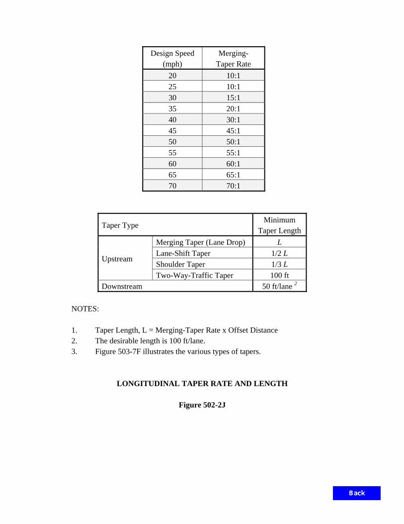
Design Speed
(mph) Merging-
Taper Rate 20 10:1 25 10:1 30 15:1 35 20:1 40 30:1 45 45:1 50 50:1 55 55:1 60 60:1 65 65:1 70 70:1
Taper Type Minimum
Taper Length
Upstream
Merging Taper (Lane Drop) L
Lane-Shift Taper 1/2 L Shoulder Taper 1/3 L Two-Way-Traffic Taper 100 ft
Downstream 50 ft/lane 2
NOTES: 1. Taper Length, L = Merging-Taper Rate x Offset Distance
2. The desirable length is 100 ft/lane. 3. Figure 503-7F illustrates the various types of tapers.
LONGITUDINAL TAPER RATE AND LENGTH
Figure 502-2J

Roadway Type Application on
Tangent Sections
Application on
Curves Spacing (ft) Placement
Interstate or Freeway Required1, 2
Required2 400 Right side
Expressway Required1, 2
Required2 400 Right side
Interchange Ramp Required Required 100 Outside
curve side
Multilane Transition
to Two-Lane Required Required Varies
3 Varies
3
Other Highway Optional Optional 500 Right side4
NOTES:
1. Delineators are not required on tangent sections where raised pavement markers are used.
2. Delineators are not required where continuous highway lighting is used between interchanges.
3. See Figures 502-2L – 502-2P and the INDOT Standard Drawings for spacing and placement of delineators
within transition areas.
4. Delineators on the left side of a conventional two lane highway shall be white.
5. Color. The delineator color should match the color of the line it is offset from. For example, if the edge
line is white, the delineator shall be white. For the left side of divided highways, if used, the delineator shall
be yellow. Red delineators may be used on the reverse side of any delineator post for motorists who may be
traveling the wrong way on one-way roadways (e.g., ramps).
6. Guardrail. Barrier delineators are required on all concrete median barriers, temporary concrete median
barriers, and concrete railings. Delineators may be provided on or adjacent to guardrail.
7. Islands. Delineators may be used to outline raised islands.
8. No-Passing Zones. The end of the no-passing zone is normally indicated on the right side of the roadway
with three, horizontally aligned, white delineators.
9. Height. The top of the delineator should be placed so that the top of the reflecting head is approximately 4
ft above the surface of the nearest travel lane.
10. Offset. Delineators should be offset a constant distance from the roadway edge unless guardrail or other
obstructions intrude into the space between the pavement edge and the extension of the line of delineators.
Typically, delineators should not be placed less than 2 ft or more than 8 ft from the outside edge of the
shoulder.
11. Spacing Gaps. Where normal uniform spacing is interrupted by driveways, cross roads, etc., the delineator
should be moved to either side provided the distance does not exceed one-quarter of the normal spacing. If
these criteria are exceeded, the delineator may be deleted.
DELINEATOR APPLICATION, PLACEMENT, AND SPACING
Figure 502-2K

1
22
Delineators
1
2
12’-0"
12’-0"
12’-0"
Center Line
4" Double Solid Yellow
Lane Line
4" Broken White
Edge Line
4" Solid White
24’-0"
1000’
500’500’
125’
24’-0"
locations may be required to meet field conditions.
Adjustments to the signing and pavement marking 2.
within the transition area.
RPM’s are desirable along all edge and center lines 1.
NOTES:
(Lane Shift)
L/2
(Lane Merge)
L/2
Edge Line
4" Solid White
Tangent Section
Optional
Edge Line
12’-0" Solid White
Figure 502-2L
4-Lane Undivided to 2-Lane Undivided
TRANSITION MARKINGS
Traffic Direction
and application.
See IMUTCD 3B.20 for lane reduction arrow design
See Figure 502-2J for taper lengths.
See Section 502-2.06 for delineator spacing.
3
3
W4-2
(Optional)
R4-1
(Optional)
R4-1

P.R.C.
P.T.
P.C.
M.P.H.
XX
Lane Line
4" Broken White
Center Line
4" Broken Yellow
15’-0"
Edge Line
4" Solid Yellow
Edge Line
4" Solid White
Edge Line
12" Solid White
Edge Line
4" Solid White
Center Line
4" Double Yellow
24’-0"
Edge Line
4" Solid White 1200’
This transition design should only be used for existing conditions.3.
be required to meet field conditions.
Adjustments to the signing and pavement marking locations may 2.
transition area.
RPM’s are desirable along all edge and center lines within the 1.
NOTES:
2
1
d
dd
Delineators
d
2
3
1
1 11
3
2
24’-0"
24’-0"
3
Traffic Direction
Optional
See Section 502-2.06 for delineator spacing.
d = Advance Warning Distance, See IMUTCD Table 2C - 4.
Figure 502-2M
4-Lane Divided to 2-Lane Undivided
TRANSITION MARKINGS
W6-2
W3-1PW4-2
R4-1
R5-1a
W1-6
R5-1
W6-3 W14-3
W6-1R4-1R4-7

P.R.C.P.C.
P.T.
This transition design should only be used for existing conditions.3.
be required to meet field conditions.
Adjustments to the signing and pavement marking locations may 2.
transition area.
RPM’s are desirable along all edge and center lines within the 1.
NOTES:
ddd
Delineators
Edge Line
12" Solid Yellow
Edge Line
4" Solid White
Center Line
Yellow
4" Double Solid
1200’
Center Line
4" Broken Yellow
1
2111
3
Figure 502-2N
4-Lane Divided to 2-Lane Undivided
TRANSITION MARKINGS
1
2
3
Traffic Direction
Optional
See Figure 502-2J for taper lengths.
d = Advance Warning Distance, See IMUTCD Table 2C - 4.
2d
(Lane Merge)
L
Edge Line
4" Solid White
Edge Line
4" Solid Yellow
Lane Line
4" Broken White
24’-0"
24’-0"
15’-0"
24’-0"
W6-2 W4-2:L R4-1
R5-1a
R5-1
W14-3 W6-3
W6-1R4-1W1-6R4-7

ON
LY
ONLY
Figure 502-2 O
TRAFFIC CONTROL WORD/SYMBOL MARKINGS
1 1– 20’-0"
for high speed roads
times the height of characters
low speed roads and up to 10
the height of characters for
Space between words 4 times
major street.
if there is a lane-drop or a shared left-thru lane on the
Provide lane control arrows for all lanes on an approach 3
than 250’. Place at beginning of full width turn lane.
Required in lane-drop situation or if turn lane is greater 2
Required in lane-drop situation only.1
– 20’-0"
– 20’-0"
– 2
0’-0"
2
– 20’-0"3

Figure 502-2P
TRUCK-CLIMBING LANE MARKINGS
for sight distance restriction
beginning of taper or as needed
Begin 4" Solid Yellow Line at
4" Solid White Line
100’ Solid White Edge Line4’ Broken White Line
100’ 125’
500’
4" Solid White Edge Line
for sight distance restriction
4" Solid Yellow Line as needed4" Broken Yellow Line
(Lane Merge)
L
Delineators
2
1
See Figure 502-2J for taper length.
See Section 502-2.06 for delineator spacing.1
2
W9-1
RIG
HT
LA
NE
EN
DS
W4-2

Edge Line
8" Solid White
Yellow Center Line
Double 4" Solid
Edge Line
8" Solid White
24" Stop Bar
Edge Line
4" Solid White
2’-0"
Edge Line
4" Solid White
2’-0"
Raised Corrugated Island
At 20’ Spacing
12" White Lines
Double 4" Solid Yellow Center Line
CHANNELIZED ISLAND MARKINGS
Triangular Island
Figure 502-2Q
Edge Line
4" Solid White
(Optional)
24" Yield Line

Yellow Lines at 40’ spacing
For posted speed limit = 50 mph, 24" Solid
Yellow Lines at 20’ spacing
For posted speed limit = 45 mph, 12" Solid
Center Line
4" Double Solid Yellow Edge Line
4" Solid White
Median Lines
8" Solid Yellow
Edge Line
4" Solid White Center Line
4" Double Solid Yellow
CHANNELIZED ISLAND MARKINGS
Flush or Raised Corrugated Elongated Island
Figure 502-2R

Figure 502-3A
TYPICAL WIRELESS VEHICLE-DETECTION SYSTEM
2 Ethernet Cables
Ethernet Cable
Ethernet Cable
Controller Cabinet
N N NN
N
N N
NN
N N
N N
NN
N
NN N N
N
N
N
N N
N
N
N
N N
N
C
C C
C
CC
C
C C
LEGEND:
Type N Sensor
Type C Sensor
Handhole
Receiver Processor
Wireless Repeater
2-in. Conduit
NOTES:
1. One in-pavement sensor is required for each indecision
zone detection zone.
2. Wireless repeaters for indecision zone loops should be
mounted to 15-ft signal pedestals on Type A foundations.

2 Ethernet Cables
Ethernet Cable
Ethernet Cable
Controller cabinet
C
C
Figure 502-3B
TYPICAL HYBRID WIRELESS VEHICLE-DETECTION SYSTEM
C
LEGEND:
Type C Sensor
Handhole
Receiver Processor
Wireless Repeater
2-in. Conduit
Inductive Loop-Detection Zone
mounted to 15-ft signal pedestals on Type A foundations.
2. Wireless repeaters for indecision zone loops should be
zone detection zone.
1. One in-pavement sensor is required for each indecision
NOTES:

Figure 502-3C
PARTIAL BRIDLE CONFIGURATION
CABLE-SPAN MOUNTED SIGNAL
Direction
Traffic
Signal Head
3 Section
Signal Head
Left Turn
3 Section
LEGEND:

Figure 502-3D
COMBINATION SIGNAL-LUMINAIRE POLE
Lane Line
Center Line
Lane Line
Crossw
alkPe
destrian
Crosswalk
Pedestrian
Center Line
Luminaire
Street Name Sign
Backplates
With Optional
Traffic Signal
Pedestrian Signal
Push Button
Sign
Push Button
Sidew
alk
Stop Line

Beacon
Flashing
Optional
Signal Head
3-Section
Direction
Traffic
LEGEND:
FL*
FL*
FL*
Flashing Beacon
Sign with Optional
Signal Ahead Warning
Signal Indication
Pole-Mounted Near-Side
Figure 502-3E
Rural Two-Lane Road with Obstructed Sight Distance
SIGNAL HEAD PLACEMENT

min.
10’-0"
3’-0" to 4’-0"
Support
Optional On-Pole
Direction
Traffic
Signal Head
3 Section
LEGEND:
Figure 502-3F
Offsetting Intersection
SIGNAL HEAD PLACEMENT

Figure 502-3G
Truck Blocking View of Signal Heads
Rural Two-Lane Road with
SIGNAL HEAD PLACEMENT
Signal Head
3 Section
LEGEND:
Direction
Traffic

PA
RKIN
G
3’-0"
3’-0"
Direction
Traffic
Signal Head
3 Section
LEGEND:
Figure 502-3H
and Parking on Near Side
Approaching Lanes with Permissible Phase
SIGNAL HEAD PLACEMENT

PA
RKIN
G
2’-0"
Min.
10’-0"
Direction
Traffic
Signal Head
3 Section
LEGEND:
Figure 502-3 I
Permissible Phase and Parking on Far Side
Approaching Lanes with Left-Turn Lane with
SIGNAL HEAD PLACEMENT
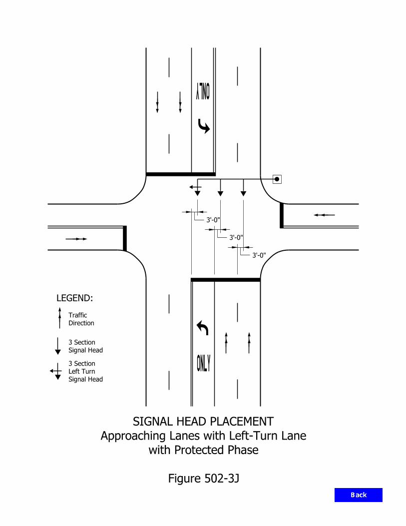
3’-0"
3’-0"
3’-0"
Direction
Traffic
Signal Head
3 Section
Signal Head
Left Turn
3 Section
LEGEND:
Figure 502-3J
with Protected Phase
Approaching Lanes with Left-Turn Lane
SIGNAL HEAD PLACEMENT

3’-0" 3’-0"
Direction
Traffic
Signal Head
3 Section
LEGEND:
Figure 502-3K
with Permissible Phase
Approaching Lanes with Left-Turn Lane
SIGNAL HEAD PLACEMENT

Direction
Traffic
Signal Head
3-Section
LEGEND:
Yellow Arrow
with Flashing
Signal Head
Left-Turn
4-Section
4’-0"4’-0"
4’-0"
Figure 502-3L
with Protected/Permissible Phase
Approaching Lanes with Left-Turn Lane
SIGNAL HEAD PLACEMENT

3’-0"
3’-0"
3’-0"
3’-0"
Direction
Traffic
Signal Head
3 Section
Signal Head
Left Turn
3 Section
LEGEND:
Figure 502-3M
Left-Turn Lane Protected Phase
Multi-Lane Roadway Approaching Lanes with
SIGNAL HEAD PLACEMENT

Line
Dotted
Yellow
Line
Dotted
Yellow
Signal Head
3 Section
Signal Head
Left Turn
3 Section
Direction
Traffic
LEGEND:
3’-0" 3’-0"
Line
White Dotted
3’-0" 3’-0"
Figure 502-3N
with Protected Phase
Approaching Lanes with Two Left-Turn Lanes
SIGNAL HEAD PLACEMENT
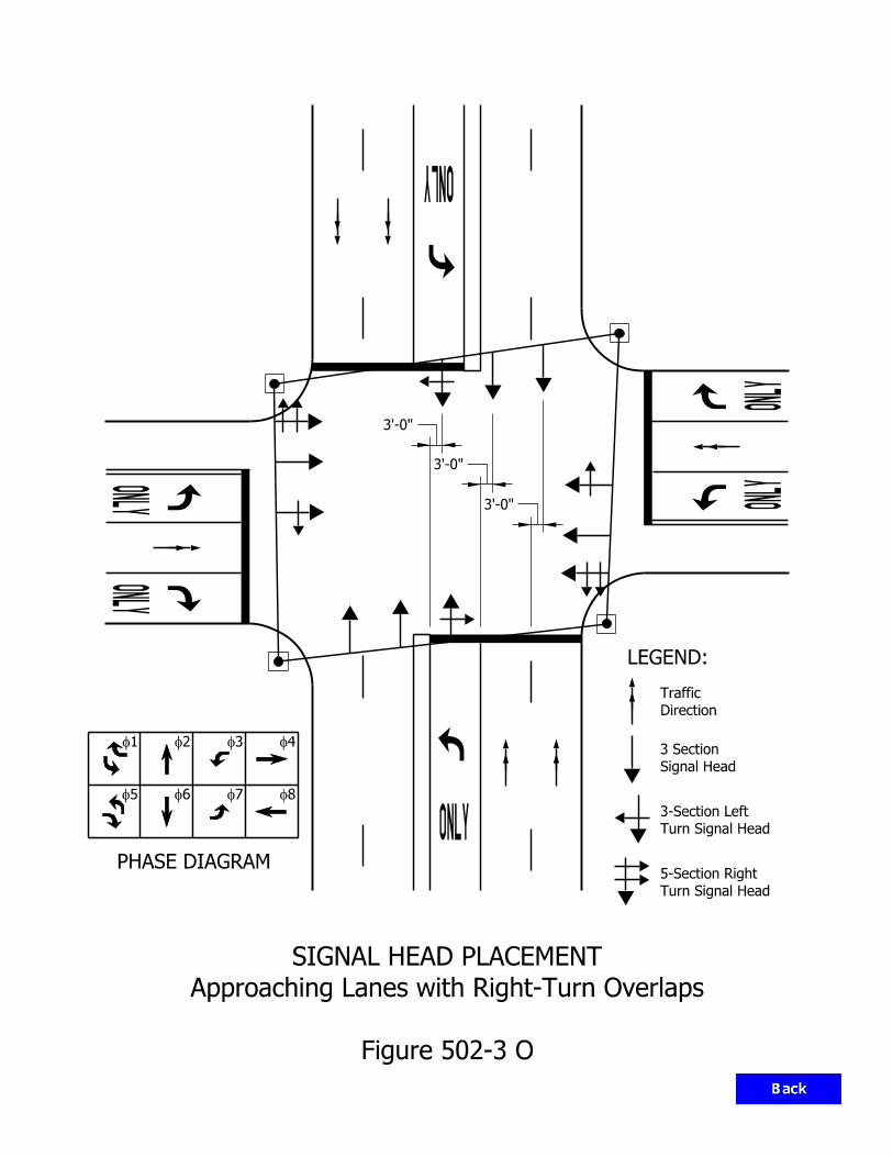
PHASE DIAGRAM
Signal Head
3 Section
Turn Signal Head
3-Section Left
Turn Signal Head
5-Section Right
1f 2f 3f 4f
5f 6f 7f 8f
3’-0"
3’-0"
3’-0"
LEGEND:
Direction
Traffic
Figure 502-3 O
Approaching Lanes with Right-Turn Overlaps
SIGNAL HEAD PLACEMENT

SEQUENCE OF PHASES,
EIGHT-PHASE DUAL-RING CONTROLLER
Figure 502-3P
Phases in Ring 1
Phases in Ring 2
Barrier
1f 2f 3f 4f
5f 6f 7f 8f

N
TRAFFIC MOVEMENTS
PHASE DIAGRAM
Major
Minor
2f 8f
1f 2f 3f 4f
8f7f6f5f
Figure 502-3Q
THREE-PHASE OPERATION
T-INTERSECTION
LEGEND:
Direction
Traffic
1f

Figure 502-3R
MULTI-LANES APPROACHES
FOUR-PHASE OPERATION
T-INTERSECTION
TRAFFIC MOVEMENTS
PHASE DIAGRAM
1f 2f 3f 4f
8f7f6f5f
1 & 6f 2 & 6f 8f
N
Minor
Major
Direction
Traffic
LEGEND:

N
Figure 502-3S
FOUR-PHASE OPERATION
TYPICAL INTERSECTION
TRAFFIC MOVEMENTS
PHASE DIAGRAM
Major
Minor
& 6 2f 4 & 8f
1f 2f 3f 4f
5f 6f 7f 8f
LEGEND:
Direction
Traffic

N
TRAFFIC MOVEMENTS
PHASE DIAGRAM
Major
Minor
1f 2f 3f 4f
5f 6f 7f 8f
1f 2f 4 & 8f
LEGEND:
Direction
Traffic
Figure 502-3T
SEPARATE SPLIT PHASES FOR MAJOR STREET
FOUR-PHASE OPERATION

N
TRAFFIC MOVEMENTS
PHASE DIAGRAM
Major
Minor
2 & 6f 3f 4f
1f 2f 3f 4f
5f 6f 7f 8f
LEGEND:
Direction
Traffic
Figure 502-3U
SEPARATE SPLIT PHASE FOR MINOR STREET
FOUR-PHASE OPERATION

N
TRAFFIC MOVEMENTS
Major
Minor
1f 2f 3f 4f
5f 6f 7f 8f
1f 4 & 8f6 & 2f
LEGEND:
Direction
Traffic
6.f1 omits fNOTE:
PHASE DIAGRAM
Figure 502-3V
EXCLUSIVE PEDESTRIAN PHASE
FIVE-PHASE OPERATION

LEGEND:
Direction
Traffic
TRAFFIC MOVEMENTS
PHASE DIAGRAM
1 & 5f & 6 2f 4 & 8f
1f 2f 3f 4f
5f 6f 7f 8f
Figure 502-3W
SEPARATE LEFT-TURN PHASE FOR MAJOR STREET
SIX-PHASE OPERATION
N
Major
Minor

TRAFFIC MOVEMENTS
6f1 & f
7f4 & f
5f1 & f
5f2 & f
8f3 & f
8f4 & f
7f3 & f
6f2 & f
Figure 502-3X
DUAL RING
EIGHT-PHASE OPERATION

4f 7f
5f
2f1f
6f
f8f3
N
7f
4f
5f 2f
3f
8f
1f6f
Figure 502-3Y
TYPICAL VEHICLE MOVEMENT AND PHASE NUMBERING
1f 2f 3f 4f
8f7f6f5f
East / West Major
PHASE DIAGRAM
East / West Major
VEHICLE MOVEMENTS
1f 2f 3f 4f
8f7f6f5f
North / South Major
VEHICLE MOVEMENTS
North / South Major
PHASE DIAGRAM

LEADING-LEFT TURN PHASE
ADVANTAGES DISADVANTAGES Increases intersection capacity of 1- or 2-lane approach without left-turn lane if compared to 2-phase traffic signal operation. Minimizes conflict between left-turn and opposing straight-through vehicles clearing the left-turn vehicles through the intersection first. Drivers tend to react quicker than with lagging-left operations.
Left-turning vehicles completing their movement may delay the beginning of the opposing through movement when the green is exhibited to the stopped opposing movement. Opposing movements can make a false start in response to the movement of the vehicles with the leading green. Where there is no left-turn lane, an obstruction to the left-turn movement is created if a through vehicle is present.
LAGGING-LEFT TURN PHASE
ADVANTAGES DISADVANTAGES Both directions of through traffic start at the same time. Approximates the normal driving behavior of vehicle operators. Provides for vehicle/pedestrian separation as pedestrians usually cross at the beginning of straight-through green. Where pedestrian signals are used, pedestrian signals have cleared the intersection before the beginning of the lag-green interval. Cuts off only the platoon stragglers from adjacent interconnected intersections.
Left-turning vehicles can be trapped during the left-turn yellow change interval where used with 5-section heads, as opposing through traffic is not stopping as expected. Creates conflicts for opposing left turns at start of lag interval because opposing left-turn drivers expect both movements to stop at the same time. Where there is no left-turn lane, an obstruction to the through movement during the initial green interval is created.
NOTE: The disadvantages inherent in lagging-left operations are such that they are used only for a coordinated signal system, pre-timed operation, or specific situations in actuated control, such as a T intersection.
COMPARISON OF LEFT-TURN PHASE ALTERNATIVES
Figure 502-3Z

Approach Posted Speed
(mph)
Passage Time in Seconds from Detector to Stop Bar
1 2 3 4 51 6 7
20 29 53 87 116 145 174 193
25 36 78 108 144 180 216 252
30 44 88 132 176 220 264 308
35 51 102 153 204 255 306 357
40 59 118 177 236 295 354 413
45 66 132 198 264 330 396 462
50 73 146 219 292 365 438 511
55 81 162 243 324 405 486 567
60 88 176 264 352 440 528 616
65 95 190 285 380 475 570 665
Legend: 0 Basic Controllers 0 Variable Initial Only 0 Density 0 Indecision Zone
1 INDOT typically uses Passage Time of 5 sec.
DETECTION SETBACK DISTANCE
Figure 502-3AA

preferred.
each loop, counting with 4 loops is
loop system and crosses the center of
concerns. If a vehicle squarely enters the
encroachment or early-departure
The through lanes should not have
THROUGH LANES
loops in the lane is recommended.
the left-turn lanes. Counting with all
will eliminate such encroachment onto
A raised median as shown in Diagram B 2.
recommended.
left-turn lanes. Counting with Loop 4 is
reduce left-turn encroachment onto the
shown in Diagram A, can be used to
Dotted lines or staggered stop line, as 1.
LEFT-TURN LANES
the edge of the lane and the edge of loop.
and 5 should be 6 ft, with 3 ft between
The minimum distance between Loops 1 3.
counts.
through-plus-right and right-turn-lane
with Loops 4 and 5 will provide accurate
If Loop 5 is beyond the stop line, counting 2.
through-lanes and right-turn-lane counts.
with Loops 1 and 5 will provide accurate
depart before crossing Loop 1. Counting
as shown in Diagram A, a vehicle will
If the lane at stop line is wider than 12 ft 1.
RIGHT-TURN LANES
1
2
3
4
1
2
3
4
1
2
3
4
5 1
2
3
4
1
2
3
4
3
4
2
1
5
Figure 502-3BB
COUNTING LOOP SELECTION
Loop
Non-Counting Detector
Counting Detector Loop
LEGEND:
DIAGRAM BDIAGRAM A

METHOD A METHOD B
4
3
2
11
4
3
2
1
4
3
2
1
4
3
2
11
4
3
2
1
4
3
2
1
Figure 502-3CC
FRONTAGE ROADS AND PARKING LOTS
COUNTING LOOP SELECTION
Loop
Non-Counting Detector
Counting Detector Loop
LEGEND:
Access should be provided for the design vehicle.
counting difficult.
loops, causing them to overcount. This makes
turning off the main road will often cross these
loops in one lane to get in desired lane. A vehicle
A vehicle entering the detection zone will often cross
accurate counts.
into its intended lane, loop 1 can be used to provide
Once a vehicle is channeled away from the counting loops
A median will eliminate turn encroachment.
road, and will keep it out of the lanes being counted.
A raised median will channel a vehicle turning off the main

Loops
Advance
Loops
Advance
Loops
Advance
2 2
4
3
2
1
2
1 1
1
2
3
4 2
1
2
3
4 111
1 1
DIAGRAM A DIAGRAM B DIAGRAM C
Maneuvering Area
Non-Counting Detector Loop
Counting Detector Loop
LEGEND:
close to the left-turn loops to minimize the cost of the installation.
to the left or right of the storage lane as shown in Diagram C, the counting loops should be installed
lanes as shown in Diagram B. If the location of the advance loops is where a vehicle is maneuvering
are located ahead of the storage lanes as shown in Diagram A. or after the beginning of the storage
advance loops based on the posted speed limit. Counting can be done with the advance loops if they
Counting loop selection is based on the length of the storage lanes and on the placement of the
Figure 502-3DD
ADVANCED LOOPS
COUNTING LOOP SELECTION

Foundation
Type Soil Properties Support
Arm Length, L (ft)
A Cohesive, Su, or Cu = 750 lb/ft; or
Sand, Friction Angle = 30 deg
Bearing Capacity = 1200 psf, and
Coefficient of Friction = 0.3
Drilled Shaft ≤ 35
B Drilled Shaft 35 < L ≤ 60
C Cohesive, Su, or Cu = 750 lb/ft; or
Sand, Friction Angle = 30 deg
Bearing Capacity = 1200 psf, and
Coefficient of Friction = 0.3
Spread Footing ≤ 35
D Spread Footing 35 < L ≤ 60
SIGNAL CANTILEVER STRUCTURE FOUNDATION TYPE DETERMINATION
Figure 502-3EE

1
Device Area, ft2 Weight, lb Signal Head with Backplate, 3 Sec., Lens Dia. 12 in. 8.7 35 Signal Head with Backplate, 5 Sec., Lens Dia. 12 in. 13.1 55 Regulatory Sign, 36 in. x 30 in. 7.5 19 Street-Name Sign, 18 in. x 96 in. 12 30 Street-Name Sign, 18 in. x 132 in. 16.5 41 Mounted Camera 1 20 Top-Pole Luminaire 2.4 53
AREA AND WEIGHT OF DEVICE TO BE MOUNTED ON SIGNAL CANTILEVER
Figure 502-3FF
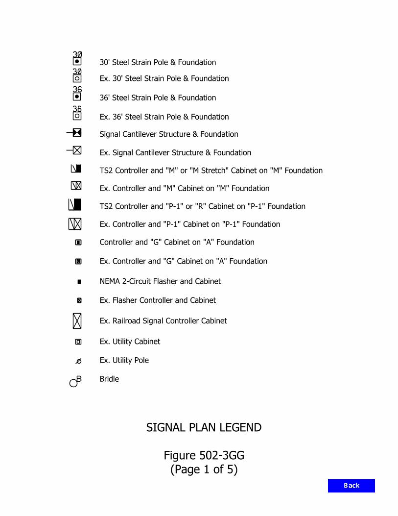
30
30
36
36
B
30’ Steel Strain Pole & Foundation
Ex. 30’ Steel Strain Pole & Foundation
36’ Steel Strain Pole & Foundation
Ex. 36’ Steel Strain Pole & Foundation
Ex. Signal Cantilever Structure & Foundation
Signal Cantilever Structure & Foundation
Ex. Controller and "M" Cabinet on "M" Foundation
Ex. Controller and "P-1" Cabinet on "P-1" Foundation
Controller and "G" Cabinet on "A" Foundation
Ex. Controller and "G" Cabinet on "A" Foundation
NEMA 2-Circuit Flasher and Cabinet
Ex. Flasher Controller and Cabinet
Bridle
Ex. Railroad Signal Controller Cabinet
Ex. Utility Cabinet
Ex. Utility Pole
TS2 Controller and "M" or "M Stretch" Cabinet on "M" Foundation
TS2 Controller and "P-1" or "R" Cabinet on "P-1" Foundation
SIGNAL PLAN LEGEND
Figure 502-3GG
(Page 1 of 5)
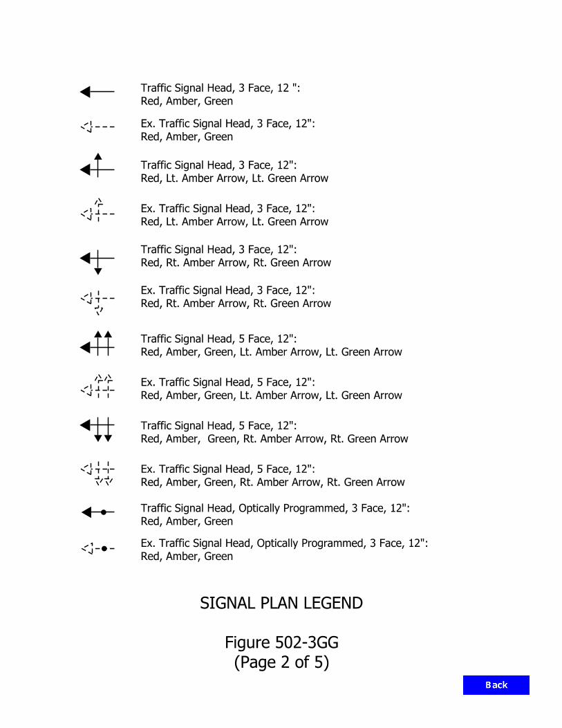
SIGNAL PLAN LEGEND
Figure 502-3GG
(Page 2 of 5)
Red, Amber, Green
Ex. Traffic Signal Head, Optically Programmed, 3 Face, 12":
Red, Amber, Green
Traffic Signal Head, Optically Programmed, 3 Face, 12":
Red, Amber, Green, Rt. Amber Arrow, Rt. Green Arrow
Ex. Traffic Signal Head, 5 Face, 12":
Red, Amber, Green, Rt. Amber Arrow, Rt. Green Arrow
Traffic Signal Head, 5 Face, 12":
Red, Amber, Green, Lt. Amber Arrow, Lt. Green Arrow
Ex. Traffic Signal Head, 5 Face, 12":
Red, Amber, Green, Lt. Amber Arrow, Lt. Green Arrow
Traffic Signal Head, 5 Face, 12":
Red, Rt. Amber Arrow, Rt. Green Arrow
Ex. Traffic Signal Head, 3 Face, 12":
Red, Rt. Amber Arrow, Rt. Green Arrow
Traffic Signal Head, 3 Face, 12":
Red, Lt. Amber Arrow, Lt. Green Arrow
Ex. Traffic Signal Head, 3 Face, 12":
Red, Lt. Amber Arrow, Lt. Green Arrow
Traffic Signal Head, 3 Face, 12":
Red, Amber, Green
Ex. Traffic Signal Head, 3 Face, 12":
Red, Amber, Green
Traffic Signal Head, 3 Face, 12 ":
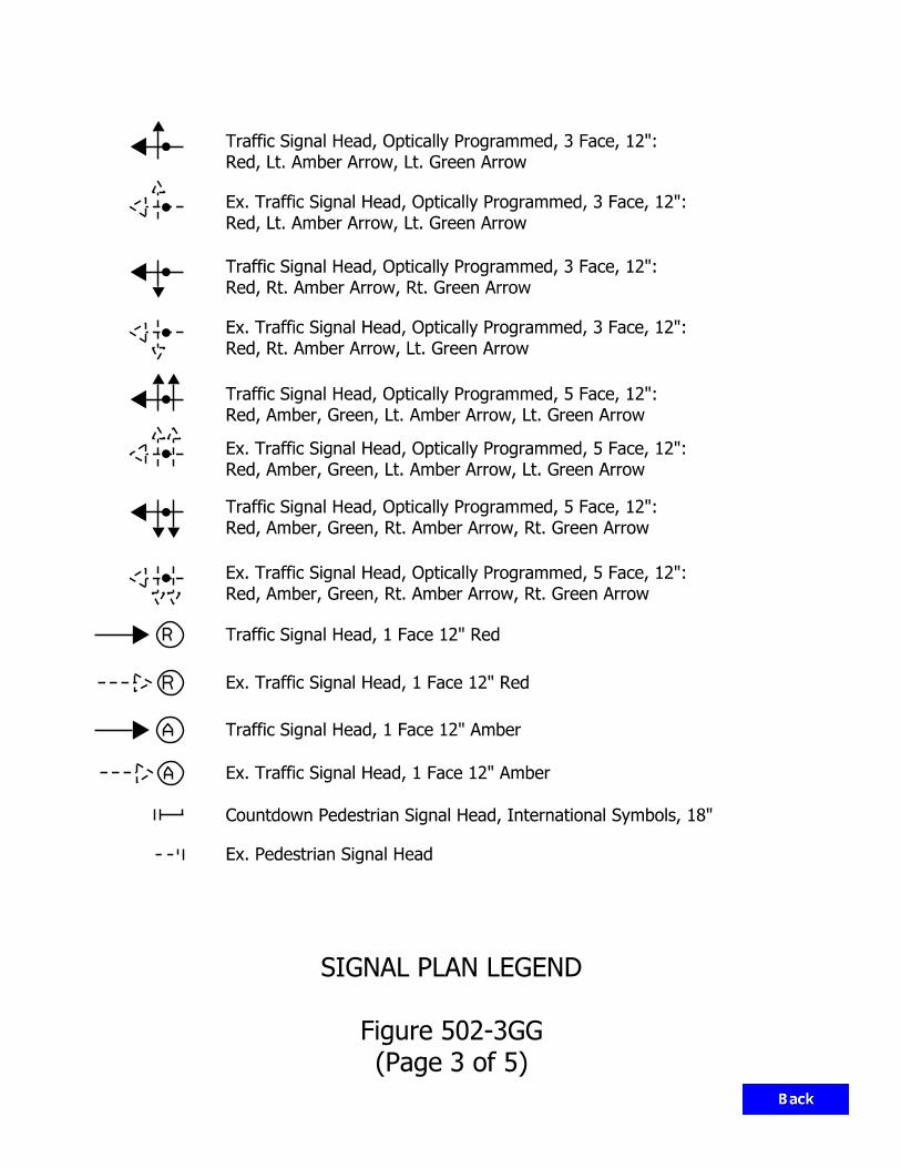
A
A
R
R
SIGNAL PLAN LEGEND
Figure 502-3GG
(Page 3 of 5)
Ex. Traffic Signal Head, 1 Face 12" Red
Ex. Traffic Signal Head, 1 Face 12" Amber
Traffic Signal Head, 1 Face 12" Red
Traffic Signal Head, 1 Face 12" Amber
Ex. Pedestrian Signal Head
Red, Lt. Amber Arrow, Lt. Green Arrow
Traffic Signal Head, Optically Programmed, 3 Face, 12":
Red, Lt. Amber Arrow, Lt. Green Arrow
Ex. Traffic Signal Head, Optically Programmed, 3 Face, 12":
Red, Rt. Amber Arrow, Rt. Green Arrow
Traffic Signal Head, Optically Programmed, 3 Face, 12":
Red, Rt. Amber Arrow, Lt. Green Arrow
Ex. Traffic Signal Head, Optically Programmed, 3 Face, 12":
Red, Amber, Green, Lt. Amber Arrow, Lt. Green Arrow
Traffic Signal Head, Optically Programmed, 5 Face, 12":
Red, Amber, Green, Lt. Amber Arrow, Lt. Green Arrow
Ex. Traffic Signal Head, Optically Programmed, 5 Face, 12":
Red, Amber, Green, Rt. Amber Arrow, Rt. Green Arrow
Traffic Signal Head, Optically Programmed, 5 Face, 12":
Red, Amber, Green, Rt. Amber Arrow, Rt. Green Arrow
Ex. Traffic Signal Head, Optically Programmed, 5 Face, 12":
Countdown Pedestrian Signal Head, International Symbols, 18"

P
P
ML1 ML2
ML1 ML2
SIGNAL PLAN LEGEND
Figure 502-3GG
(Page 4 of 5)
Signal Pedestal on "A" Foundation
Ex. Signal Pedestal on "A" Foundation
Disconnect Hanger
Ex. Disconnect Hanger
Signal Handhole
Ex. Signal Handhole
Ex. 2" Conduit
Ex. Octagonal Loop, 4-Turn Series
Octagonal Loop, 4-Turn Series
Preformed Loop
Ex. Preformed Loop
Microloop
Ex. Microloop
Signal Detector Housing
Ex. Signal Detector Housing
Circular Loop, 4 Turn-Series
Circular Loop, 4-Turn Series
2" Conduit
P
EX. P Ex. Pedestrian Push Button & Sign
Accessible Pedestrian Push Button & Sign

SIGNAL PLAN LEGEND
Figure 502-3GG
(Page 5 of 5)
24" Stop Line
Ex. 24" Stop Line
Ex. Pavement Message Markings
Pavement Message Markings
Existing R/W
Ex. Radio Antennae
Radio Antennae

INDOT typically uses mounting heights of 40 ft.
(E.M.H.)
Height
Mounting
Effective (M.H.)
Height
Mounting
Mast Arm Rise
Ele
vation
1
Luminaire
Mast Arm
Standard
Light
Base
Transformer
Foundation
Shoulder
Edge of Travel Lane
Edge of
1
Figure 502-4A
TYPICAL LIGHT-POLE INSTALLATION
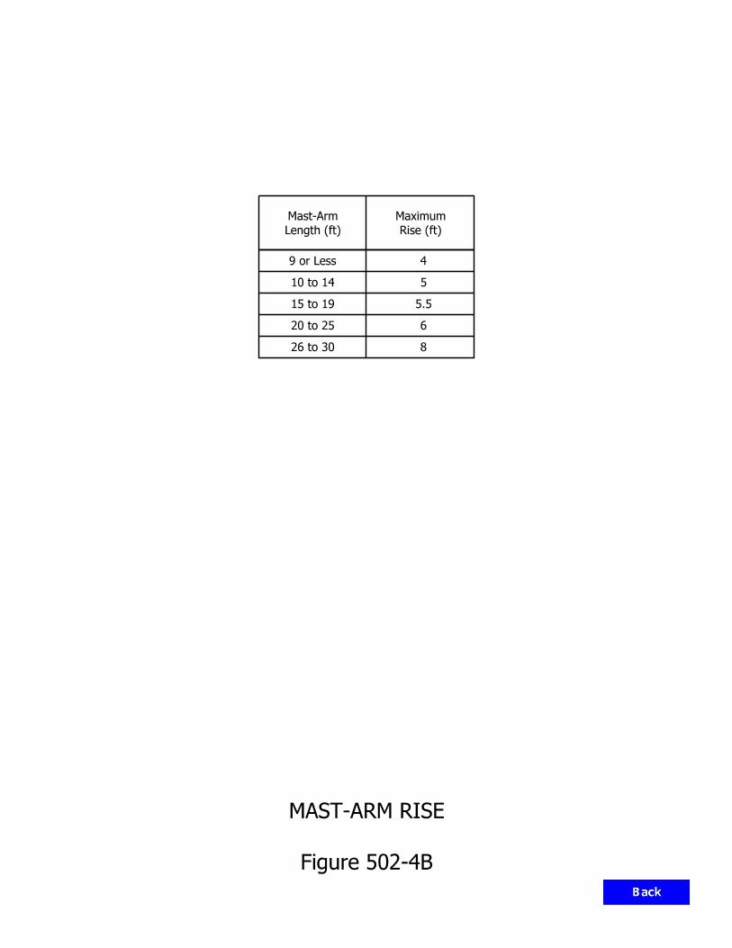
Length (ft)
Mast-Arm
Rise (ft)
Maximum
9 or Less 4
5
5.5
6
8
10 to 14
26 to 30
20 to 25
15 to 19
Figure 502-4B
MAST-ARM RISE

100
175
250
400
1000
750
70
50
100
150
200
250
310
400
1000
40
50180
90
30
60
230 33000
8000
13500
22500
18000
18000
18000
18000
18000
10000
31400
21400
12850
7610
4570
17201800
4800
1102 130000
51000
37000
22000
16000
9500
6400
4000
25
14 32
35
85
125
175
3600
33100
100280
82000
900025
30
45
55
59
52
98
19
28
23
25
42
47272
295
125
205
455
809
1052
69
123
175
6200
22100
14400
117000
45000
33300
25200
19800
18
35
55
135
24000
24000
24000
24000
24000
24000
24000
24000
24000
11000
16000
15000
15000
79000
60000
20800
5450
8550
HIGH-PRESSURE SODIUM
LOW-PRESSURE SODIUM
292 28000
Wattage
Ballast
Approx.
Wattage
Total
Lumens
Initial
Lumens
Mean
Life (h)
Average
600011700 7400
19100 6000
METAL HALIDE
102
Wattage
Lamp1 2
4
5
5
6
3
7 7
7 7
7 7
Horizontal7
Used for high-mast lighting.6
Used for conventional highway lighting.5
Used for a highway underpass.4
Used for sign illumination.3
Shown as the highest loss known for the commonly-used ballast types.2
The common wattages are shown. For others see the IES Lighting Handbook.1
NOTES:
Figure 502-4C
LAMP DATA

Lamp Lumen Depreciation Factor, LLD 0.90*
Luminaire Dirt Depreciation Factor, LDD 0.87 Percent of Voltage Drop Permitted 10% Pole Height 40 ft
150 W, HPS (Underpass) Lamp Size 250 W or 400 W, HPS (Conventional)
1000 W, HPS (High-Mast)
*For High Pressure Sodium Lamps only. For Solid State Light Sources the LLD should be as given by the manufacturer.
LIGHTING DESIGN PARAMETERS
Figure 502-40

Roadway Classification
Average Maintained Horizontal
Illuminance, Eh (ft-cd)
Uniformity Ratio
Interstate Route or Other Freeway
0.8 4:1
Expressway 1.1 to 1.6 3:1 Intersection or
City Street 0.8 4:1
Weigh Station or Rest Area Ramp
0.6 4:1
Weigh Station or Rest Area Parking Area
1.0 4:1
NOTES:
1. See Figure 51-7V for Bikeway or Trail. 2. Where pedestrian trail, bikeway, and shared pathway are adjacent to a roadway, the
design criteria for the roadway shall govern. 3. See NCHRP 672 for roundabout lighting levels.
ILLUMINANCE DESIGN CRITERIA
Figure 502-4E

AP
0° Ref
SET BACK
SET BACK
DIRECTIONTRAFFIC
PLAN VIEW
OVERHANG (OH)
ORIENTATION ANGLE
(PROFILE VIEW)
MOUNTING HEIGHT (MH) TILT ANGLE
AIMING POINT (AP) ROTATION ANGLE
MH
270°
90°
OH
Tilt
Rotation
Direction
Traffic
Nadir
Setback
0° Ref
Nadir 0° RefNadir
Figure 502-4F
LUMINAIRE GEOMETRY
OH

S
M
L
Type V
Type IV
Type III
Type II
Type I
S
C
N
Edge
Edge
Edge
Short
Definition
Medium
Long
Center
Definition
Cutoff
Sim-Cutoff
Non-Cutoff
Center
Classification
Spacing
Classification
Width
Classification
Glare-Control
Mounting Location
Pavement
3 times MH or less for both-sides mounting
1.5 times MH or less for one-side mounting
2 times MH or less for both-sides mounting
MH or less for one-side mounting
4 times MH or less for both-sides mounting
2 times MH or less for one-side mounting
2 times MH or less
5 times MH or less
4 times MH or less
4 times MH or less
Control Requirement
More than 5 times MH
Roadway Width Served
Spacing Distance
Strict control of lighting above 80 deg vertical
Medium control of lighting above 80 deg vertical
No control of lighting above 80 deg vertical
luminaire classification used by INDOT.
502-5.06(03) item 1 or contact the Office of Traffic Engineering to determine the
INDOT does not use all of the IES classifications listed above. See review section 4.
satisfies the classification requirements and is used as shown above.
There is no assurance that these values will be achieved by a luminaire which 3.
control, in sequence. Example: M-III-S.
The complete luminaire classification consists of the spacing, width type, and glare 2.
MH = mounting height.1.
NOTES:
Figure 502-4G
LUMINAIRE CLASSIFICATION SYSTEM

III or IVLight Type
Arrangement
II or III IV or V
Mounting)(Median
Twin Mast Arms
Staggeredor
One Side
or High-MastIntersection
At-Grade
Oppositeor
Staggered
II, III or IV
PlacementLateral
to 2.0 MHPavement Width
to 1.5 MHPavement Width
Each Pavementto 1.5 MH,
Pavement Width
Pavement Width1.5 MH plus
Figure 502-4H
LUMINAIRE PLACEMENT AND LIGHT TYPE

0
1.0
1.0 0 1.0 2.0 3.0 4.0 5.0
1.0 M
H T
RL
2.7
5 M
H T
RL
1.7
5 M
H T
RL
TYPE II
RANGE
TYPE IV RANGE
VERTIC
AL P
LA
NES
RA
TIO O
F L
ON
GIT
UDIN
AL DIS
TA
NC
E T
O M
OU
NTIN
G H
EIG
HT
RATIO OF TRANSVERSE DISTANCE TO MOUNTING HEIGHT
TR
AN
SV
ERSE R
OA
DW
AY LIN
ES (
TR
L)
CONES
1.0 MH TRL
2.25 MH TRL
3.75 MH TRL
6.0 MH TRL
LONGITUDINAL ROADWAY LINES (LRL)
RA
NG
E
60°
40°
10°
0°
70°
82‰°
85°
75°
80°
20°
90° 80°70°80° 70°
40°
30°
60° 50
°
2.0
3.0
4.0
5.0
6.0
7.0
8.0
9.0
10.0
11.0
(A) TYPE I
(B) TYPE I, 4 - WAY
(C) TYPE II
(E) TYPE III
(F) TYPE IV
(G) TYPE V
(D) TYPE II, 4 - WAY
LUMINAIRE
SH
OR
T
TYPE I RANGE
DIS
TRIB
UT
OR
LO
NG
ME
DIU
M
RANGE
TYPE III
Figure 502-4 I
PLAN VIEW FOR LUMINAIRE COVERAGES

4.03.0
HOUSE SIDE
STREET SIDE
0.10
0.20
0.30
0.40
0.50
0
1.0 2.0
CO
EFFICIE
NT O
F U
TILIZ
ATIO
N
equipment types.
The coefficient-of-utilization curve will vary with various manufacturers and NOTE:
(STREET OR HOUSE SIDE)
TRANSVERSE WIDTH
LUMINAIRE MOUNTING HEIGHTRATIO =
Figure 502-4J
SAMPLE COEFFICIENT-OF-UTILIZATION CURVE
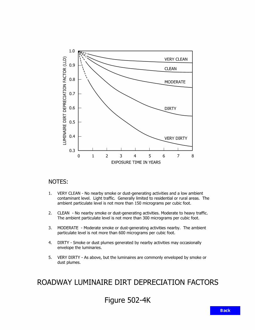
EXPOSURE TIME IN YEARS
VERY DIRTY
DIRTY
CLEAN
VERY CLEAN
MODERATE
0 1 2 3 4 5 6 7 8
0.8
0.9
0.7
0.6
0.5
0.3
LU
MIN
AIR
E DIR
T D
EP
RE
CIA
TIO
N F
AC
TO
R (
LLD)
1.0
0.4
dust plumes.
VERY DIRTY - As above, but the luminaires are commonly enveloped by smoke or 5.
envelope the luminaries.
DIRTY - Smoke or dust plumes generated by nearby activities may occasionally 4.
particulate level is not more than 600 micrograms per cubic foot.
MODERATE - Moderate smoke or dust-generating activities nearby. The ambient 3.
The ambient particulate level is not more than 300 micrograms per cubic foot.
CLEAN - No nearby smoke or dust-generating activities. Moderate to heavy traffic. 2.
ambient particulate level is not more than 150 micrograms per cubic foot.
contaminant level. Light traffic. Generally limited to residential or rural areas. The
VERY CLEAN - No nearby smoke or dust-generating activities and a low ambient 1.
NOTES:
Figure 502-4K
ROADWAY LUMINAIRE DIRT DEPRECIATION FACTORS
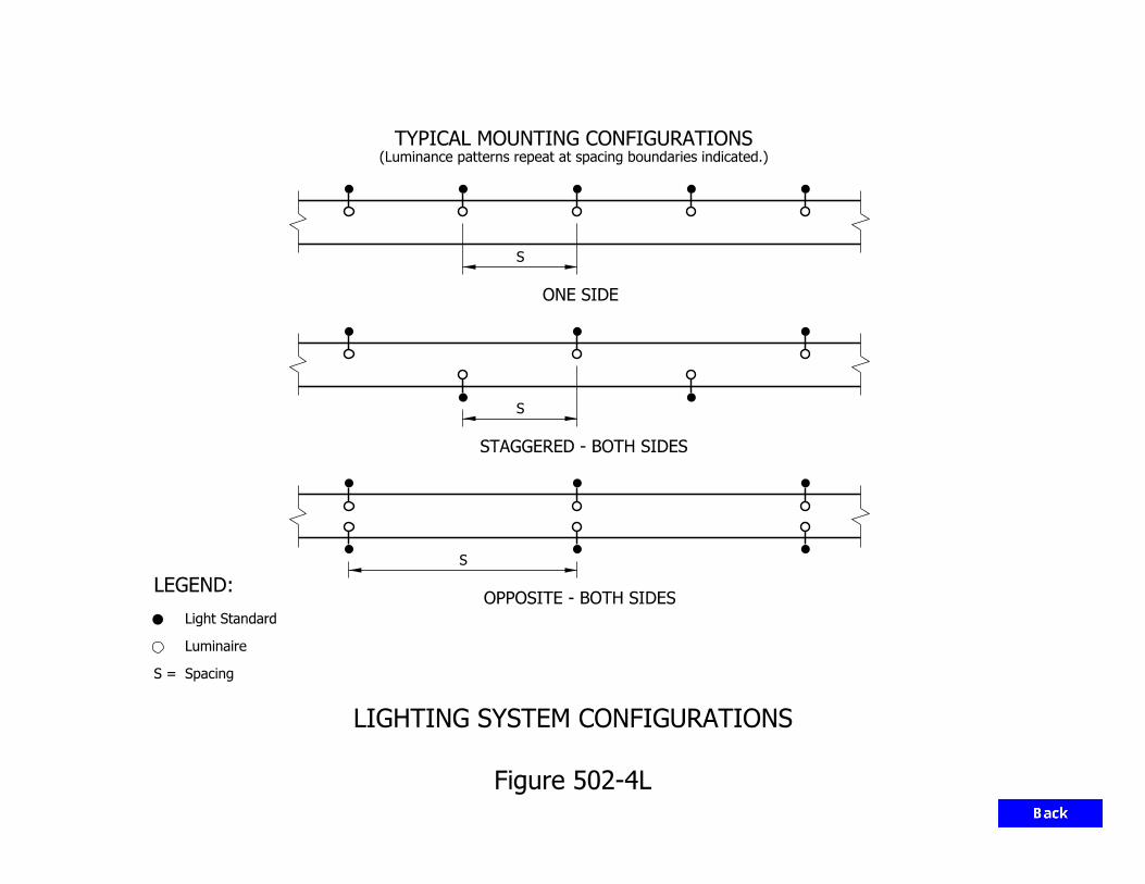
STAGGERED - BOTH SIDES
ONE SIDE
TYPICAL MOUNTING CONFIGURATIONS
OPPOSITE - BOTH SIDES
S
S
S
(Luminance patterns repeat at spacing boundaries indicated.)
SpacingS =
Luminaire
Light Standard
LEGEND:
Figure 502-4L
LIGHTING SYSTEM CONFIGURATIONS
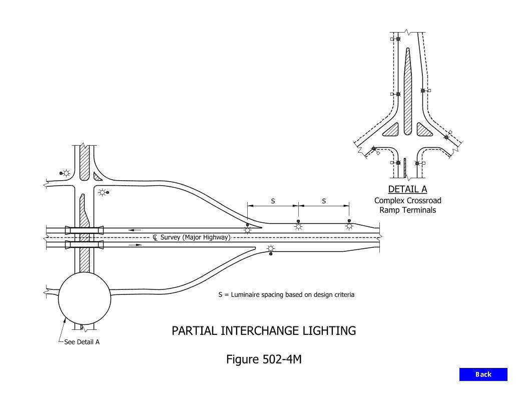
S = Luminaire spacing based on design criteria
DETAIL A
Ramp Terminals
Complex Crossroad
Survey (Major Highway)
SS
See Detail A
Figure 502-4M
PARTIAL INTERCHANGE LIGHTING

Stub of Breakaway Support
Chord Line
Ground Line
61.0 in. Chord
4.0 in. Max.
Figure 502-4N
BREAKAWAY SUPPORT STUB CLEARANCE DIAGRAM

50 ft Minimum
Gore Nose Gore Area
St
1 Pole
Painted Nose
Figure 502-4 O
POLE CLEARANCE FOR RAMP GORE
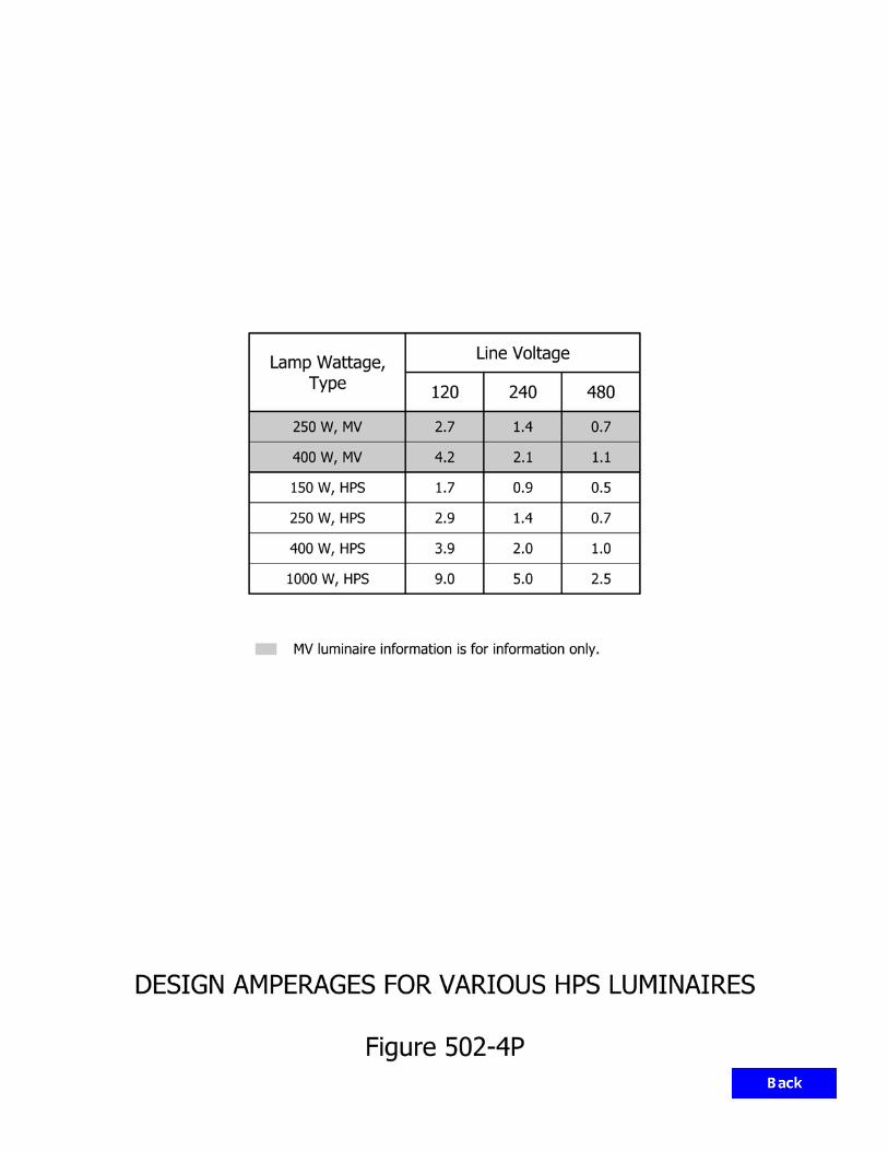
Lamp Wattage, Line Voltage
Type 120 240 480
250 W, MV 2.7 1.4 0.7
400 W, MV 4.2 2.1 1.1
150 W, HPS 1.7 0.9 0.5
250 W, HPS 2.9 1.4 0.7
400 W, HPS 3.9 2.0 1.0
1000 W, HPS 9.0 5.0 2.5
MV luminaire information is for information only.
DESIGN AMPERAGES FOR VARIOUS HPS LUMINAIRES
Figure 502-4P

Wire Size (AWG)
Resistance (Ω/mi)
10 6.55
4 1.62
COPPER-WIRE RESISTANCE
Figure 502-4Q

NEUTRAL
A
B
BLACK
2
10.8 A 8.8 A 6.8 A 4 A 2 A
86H
RED
10 A 8 A 6 A 4 A 2 A
97531
10
11
2.8 A
1.4 A
12 ft
50 ft
300 ft 200 ft 200 ft 200 ft 200 ft
200 ft150 ft50 ft450 ft 200 ft
240/480
POINT
SERVICE
ROADWAY LUMINAIRE
400-W HPS
SIGN LUMINAIRE
250-W M.V.
4
Figure 502-4R
VOLTAGE DROP CALCULATIONS EXAMPLE

Estimated Mounting Height, EMH (ft)
Lumens (HPS Light Source)
Number of Luminaires
100 400,000 4
105 ≤ EMH ≤ 120 600,000 4 or 6
125 ≤ EMH ≤ 150 800,000 6 or 8
155 ≤ EMH ≤ 200 1,600,000 6, 8, 10, or 12
NUMBER OF LUMINAIRES FOR HIGH-MAST TOWER
Figure 502-4S

Slope, S : 1 Height (ft)
2:1 ≤ S ≤ 3:1 3
3:1 < S ≤ 4:1 2
4:1 < S < 5:1 1.5
HEIGHT OF RETAINING WALL AT HIGH-MAST-TOWER CONCRETE PAD
Figure 502-4T

3" to 6"
Tower
Camera
CLS Box
Camera
CLS Box
TowerCamera
CLS Box
Control BoxControl Box
Roadway
4’-0"
4’-0"
4’-0"
4’-0"4’-0"
Figure 502-5A
TOWER ORIENTATION
CLS = Camera Lowering System
KEY:
4’-0"

Anchor
Fence
Fence
Camera
Camera
AnchorFenceFence
60’ to 80’ 60’ to 80’
4’-0" 4’-0"
15’-0"15’-0"
TurnbuckleGuide Wire with
GUIDE WIRE SECURED TO THE TOWER LEG GUIDE WIRE IN THE WORKING POSITION
Figure 502-5B
CAMERA LOWERING SYSTEM (CLS)

Cabinet
Control
Handholes
with Carriers
3" dia.,
PVC Conduit,
with Carriers
3" dia.,
PVC Conduit,
Probes (Typ.)
in Conduits
Home Run Cables
20’-0"
Figure 502-5C
NON-INVASIVE VEHICLE DETECTION
20’-0"
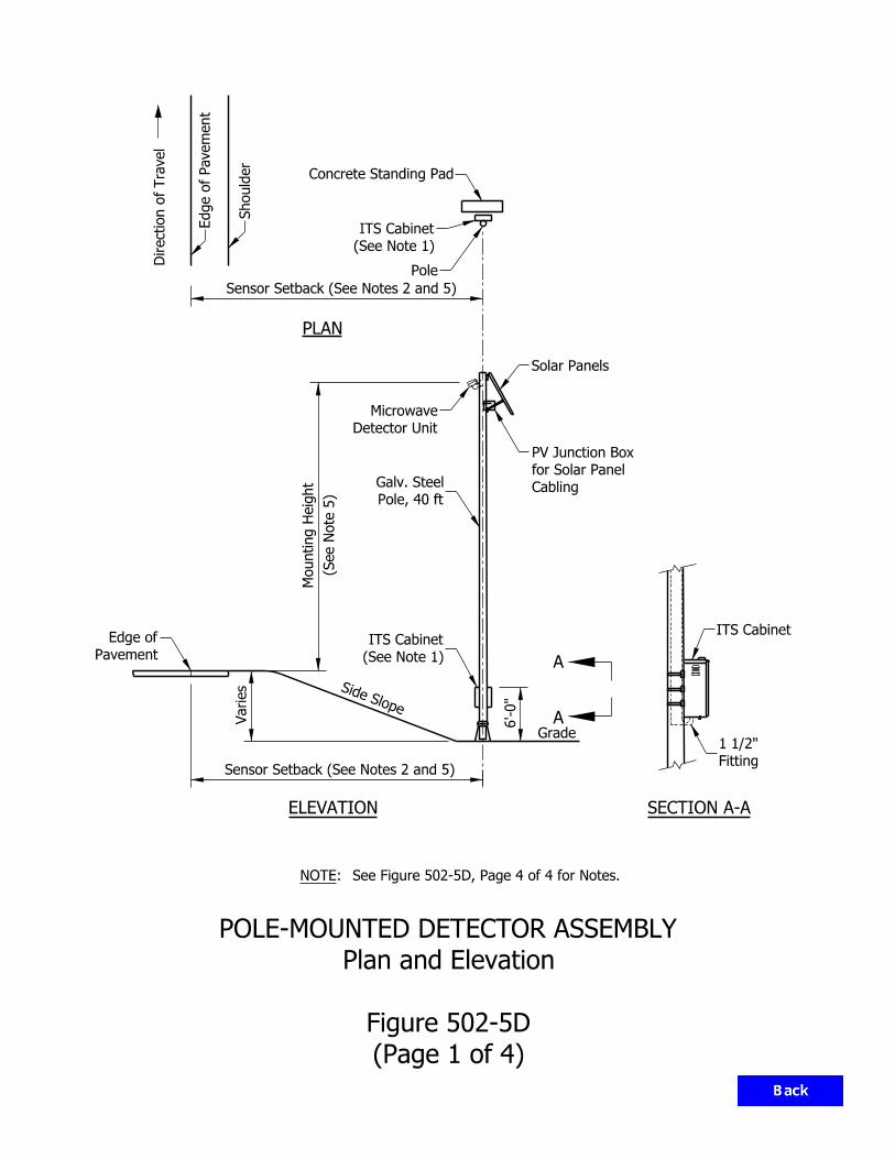
Direction of
Tra
vel
Grade
Varies
6’-0"
Sensor Setback (See Notes 2 and 5)
ELEVATION
PLAN(S
ee N
ote 5)
Mounting H
eig
ht Cabling
for Solar Panel
PV Junction Box
Edge of Pave
ment
Pole, 40 ft
Galv. Steel
A
A
Pavement
Edge of
Shoulder
Pole
Concrete Standing Pad
Side Slope
Sensor Setback (See Notes 2 and 5)
Solar Panels
(See Note 1)
ITS Cabinet
(See Note 1)
ITS Cabinet
Detector Unit
Microwave
SECTION A-A
ITS Cabinet
Fitting
1 1/2"
(Page 1 of 4)
Figure 502-5D
Plan and Elevation
POLE-MOUNTED DETECTOR ASSEMBLY
See Figure 502-5D, Page 4 of 4 for Notes.:NOTE

LB Connector
RGS Conduit - 2"
(See Note 8)
2" Weatherhead
(See Note 9)
Conduit Coupling
Steel Bands
1" Stainless
1’-0"
TO EXISTING LIGHT POLE
MICROWAVE DETECTOR MOUNTED
Spa. @ 4’-11" (Max.)
with Conduit Hangers
1" Stainless Steel Bands
Detector Unit
Microwave
Pole
Cable Strain Relief
Recommendations
per Manufacturer
Control/Power Cable
Steel Bands
3/4" Stainless
Strain Relief
Hook for
(See Note 11)
Drip Loop
(See Note 8)
2" Weatherhead
(Typ.)
Kellems Grips
Cable Access
Handhole
TO NEW LIGHT POLE
MICROWAVE DETECTOR MOUNTED
(See Notes 5 and 10)
Microwave Detector Unit
(Page 2 of 4)
Figure 502-5D
Microwave Detector Mounting Details
POLE-MOUNTED DETECTOR ASSEMBLY
See Figure 502-5D, Page 4 of 4 for Notes.:NOTE

Message Sign
To Dynamic
Downstream
Vertical Support,
Dynamic Message Sign
Clamp Kit
Steel Bands
1" Stainless
Steel Bands
1" Stainless
4’ Aluminum Arm
TO DYNAMIC MESSAGE SIGN
MICROWAVE DETECTOR MOUNTED
structure.
Angle away from sign
Horizontal Mounting Bracket.
Microwave Detector Unit on
Band-It Straps
Stainless Steel
See Note 12
Radio
Spur Low Power
Cord (See Note 11)
Outdoor Ethernet PatchLight Pole
Existing or New
TO NEW LIGHT POLE
RADIO MOUNTED
(Page 3 of 4)
Figure 502-5D
Microwave Detector Mounting Details
POLE-MOUNTED DETECTOR ASSEMBLY
See Figure 502-5D, Page 4 of 4 for Notes.:NOTE

(Page 4 of 4)
Figure 502-5D
Notes
POLE-MOUNTED DETECTOR ASSEMBLY
Use stainless steel mounting hardware or alternate per the engineer.12.
Maintain acceptable bend radius per cable manufacturer recommendation.11.
See site plans for locations of microwave detectors.10.
support.
Conduit break to be placed and covered by coupling to prevent hindrance to breakaway pole 9.
weatherhead entrance hole edges.
Rubber grommet or approved equivalent to be installed to prevent movement of cable against 8.
for future use. Additional conduits not shown for clarity in presentation.
Two additional 2" conduits shall be installed in all proposed light pole foundations and capped 7.
Proposed poles shall be standard 40’-0" roadway light poles.
Detector unit may be mounted on existing or proposed pole or tower as indicated on the plans. 6.
performed by manufacturer’s field representative.
Detector unit to detect all lanes as denoted on plans. Final setup and calibration to be 5.
height to provide optimum coverage in accordance with manufacturer guidelines.
foundation. The engineer will confirm setback, approve location and verify sensor mounting
All locations must be staked in the field by the contractor prior to installation of the pole 4.
stainless steel hex head nut and bolt and ring connector. Route ground wire internal to pole.
Ground cabinet to pole utilizing #12 stranded wire. Attachment to pole shall utilize a 1/4" 3.
edge of traveled way.
Sensor setback is measured from the edge of pavement, where edge of pavement refers to the 2.
Mount cabinet on side of pole downstream of traffic where practical.1.
:NOTES

Figure 502-5E
SCREENING STATION
TRAFFIC MONITORING SYSTEM OR WEIGHT
PROCESS FLOWCHART TO DETERMINE NEED FOR
Start PDP
End PDP
PLA
N D
EV
ELO
PM
EN
T P
RO
CESS (
PD
P)
involved?
required or
Is a station Yes
No
Document Preparation
or Screening Station
Traffic Monitoring System
Division
Technology Deployment
Designer contacts ITS
Committee
Virtual Weigh Station
Designer contacts

SYSTEM
ATR/DCS/WIM
SYSTEM
ATR/DCS/WIM
SYSTEM
ATR/DCS/WIM
SYSTEM
ATR/DCS/WIM
4
Loop
1
Loop
2
Loop5
Loop
Axle 1
Axle 2
Axle 6
Axle 5
Axle 4
Axle 7
Axle 8
6
Loop
3
Loop
10
Loop
7
Loop
8
Loop
11
Loop
9
Loop
12
Loop
10’ 12’ 12’ 12’ 12’12’ 10’
49’
90°
4’ 4’
Axle 9
Offset
Camera Axis
6’-2 5/8"
Offset
Camera Axis
6’-2 5/8"
4’ HMA
26’ PCCP
8’ HMA 8’ HMA
26’ PCCP
4’ HMA
90°
30°
90°
30°
Shoulder
Shoulder
Shoulder
Shoulder
Sensor
Temperature
VWIM
Joint
Longitudinal
End of
Joint
Longitudinal
End of
Joint
D-1 Contraction
Joint
D-1 Contraction
Joint
D-1 Contraction
Joint
D-1 Contraction
Item 4e
502-5.04(09)
See Section
Page 3 of 3.
Figure 502-5F,
See Detail B on Page 2 of 3.
Figure 502-5F,
See Detail A on
Axle 16
Axle 15
Axle 12
Axle 11
Axle 10
Axle 14
Axle 13
Axle 3
(Page 1 of 3)
Figure 502-5F
Plan
TYPICAL FOUR-LANE VIRTUAL WEIGH-IN-MOTION (VWIM) STATION OVERVIEW
37’
49’
37’
90°

Camera Axis
SYSTEM
ATR/DCS/WIM
SYSTEM
ATR/DCS/WIM
(Page 2 of 3)
Figure 502-5F
Detail A
TYPICAL FOUR-LANE VIRTUAL WEIGH-IN-MOTION (VWIM) STATION OVERVIEW
Service Point
Traffic Monitoring VWIM
Handhole
Traffic Monitoring
ITS Cabinet
Foundation
ITS Cabinet
Handhole
Traffic Monitoring
Imaging System
VWIM Camera
Shoulder
Detector Housing
Traffic Monitoring
Sensor
Temperature
VWIM
Detector Housing
Traffic Monitoring
90°
90° 3
0°
.Standard Drawing
and Pole. See the INDOT
Cable Span Sign Foundation
. Drawings
Standard See INDOT
Type 2 with Rodent Screen.
Outlet Protector Type 1 or
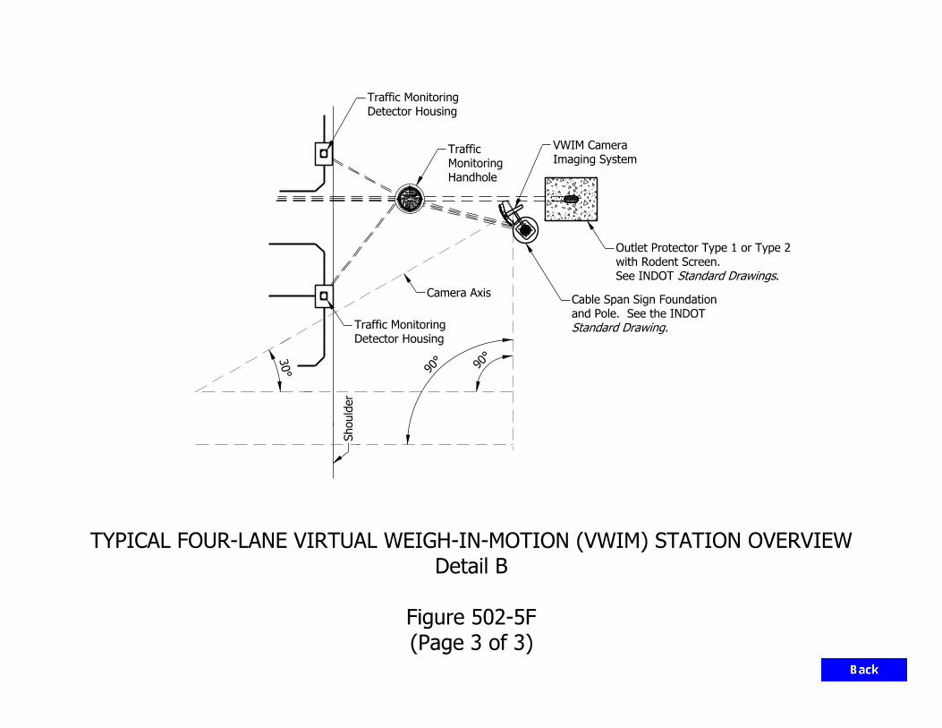
Detector Housing
Traffic Monitoring
Imaging System
VWIM Camera
Handhole
Monitoring
Traffic
Detector Housing
Traffic Monitoring
Camera Axis
Shoulder
90°
90°
.Standard DrawingsSee INDOT
with Rodent Screen.
Outlet Protector Type 1 or Type 2
Standard Drawing.
and Pole. See the INDOT
Cable Span Sign Foundation
SYSTEM
ATR/DCS/WIM
(Page 3 of 3)
Figure 502-5F
Detail B
TYPICAL FOUR-LANE VIRTUAL WEIGH-IN-MOTION (VWIM) STATION OVERVIEW
30°

INDIANA DEPARTMENT OF TRANSPORTATION—2013 DESIGN MANUAL
CHAPTER 503
Traffic Maintenance
Design Memorandum
Revision Date Sections Affected
13-01 Jan. 2013 Figure 82-6B, Figure 82-6C 13-03 Feb. 2013 82-6.03 16-06 Mar. 2016 Section 83-5.0, Figure 83-5A

INDIANA DEPARTMENT OF TRANSPORTATION—2013 DESIGN MANUAL
CHAPTER 81
Transportation Management
Plans
NOTE: This chapter is currently being re-written and its content will be included in Chapter 503 in the future.

Page 2 2013 Indiana Design Manual, Ch. 81
TABLE OF CONTENTS
LIST OF FIGURES ........................................................................................................................ 3
81-1.0 GENERAL .......................................................................................................................... 4
81-1.01 Purpose ......................................................................................................................... 4
81-1.02 Application ................................................................................................................... 4
81-1.03 TMP Development ....................................................................................................... 5
81-1.03(01) Procedure ........................................................................................................... 5
81-1.03(02) TMP Team ......................................................................................................... 7
81-1.03(03) TMP-Team Responsibilities .............................................................................. 7
81-1.04 Public-Relations Information ....................................................................................... 8
81-2.0 TRAFFIC-CONTROL MANAGEMENT .......................................................................... 9
81-2.01 Terminology ................................................................................................................. 9
81-2.02 Work-Zone Type ........................................................................................................ 10
81-2.03 Work-Zone Traffic-Control Strategy ......................................................................... 12
81-3.0 TRANSPORTATION-MANAGEMENT-PLAN STRATEGIES .................................... 12
81-3.01 Construction Phasing .................................................................................................. 13
81-3.01(01) Reconstruction by Halves or Sides .................................................................. 13
81-3.01(02) Parallel or Adjacent Reconstruction ................................................................ 14
81-3.01(03) Serial or Segmental Reconstruction ................................................................. 14
81-3.01(04) Complete Closure ............................................................................................. 15
81-3.01(05) Combinations ................................................................................................... 15
81-3.02 On-Site Strategies ....................................................................................................... 16
81-3.02(01) Traffic-Control Devices ................................................................................... 16
81-3.02(02) Capacity ........................................................................................................... 17
81-3.02(03) Other On-Site Considerations .......................................................................... 18
81-3.03 Off-Site Strategies ...................................................................................................... 19
81-3.04 Scheduling .................................................................................................................. 19
81-3.05 Incentive/Disincentive Justification ........................................................................... 20
81-3.06 A + B Bidding ............................................................................................................ 21
81-4.0 COST-EFFECTIVE ANALYSES .................................................................................... 21
81-4.01 General ....................................................................................................................... 21
81-4.02 Cost Evaluation .......................................................................................................... 22
81-4.02(01) On-Site ............................................................................................................. 22
81-4.02(02) Detour .............................................................................................................. 22
81-4.03 QUEWZ Program ....................................................................................................... 23
81-4.03(01) Inputs ................................................................................................................ 23
81-4.03(02) Outputs ............................................................................................................. 24

2013 Indiana Design Manual, Ch. 81 Page 3
FIGURES ...................................................................................................................................... 26
LIST OF FIGURES
Figure Title
81-2A Lane Constriction Work Zone
81-2B Lane Closure Work Zone
81-2C One-Lane, Two-Way Work Zone
81-2D Runaround Work Zones
81-2E Intermittent Closure
81-2F Shoulder or Median Use Work Zones
81-2G Crossover Work Zones
81-2H Chart for Identification of Feasible Work Zone Types
81-3A Reconstruction by Halves (Sides)
81-3B Parallel/Adjacent Reconstruction
81-3C Serial/Segmental Reconstruction
81-3D Editable Worksheet for Determination of Appropriate Incentive/Disincentive Amount

Page 4 2013 Indiana Design Manual, Ch. 81
CHAPTER 81
TRANSPORTATION MANAGEMENT PLANS
81-1.0 GENERAL
81-1.01 Purpose
A transportation management plan (TMP) is an overall strategy for accommodating traffic during construction. The TMP not only must address the alternatives confined to the project site, but it must also evaluate the impact traffic will have on the entire corridor. The TMP will address the proposed traffic-control plan, alternative traffic control applications, the effect traffic will have on other facilities, local concerns, cost effectiveness of various alternatives, etc. For a large project, a TMP team may be organized during the preliminary-engineering stage to study the traffic-control alternatives and their effect on the corridor. The TMP includes the traffic-control plan (TCP). The major difference between a TMP and a TCP is that the TCP focuses on the maintenance and protection of traffic within the construction zone, and the TMP addresses project-related impacts throughout the project corridor and sometimes beyond. The designer will be responsible for incorporating the TMP objectives into the TCP. Changes made during the preparation of the TCP will affect the overall TMP. For example, a lane closure which causes a large queue on a freeway may cause traffic to divert to a nearby urban arterial. This may require signal coordination, lane widening, turn restrictions, etc., on the arterial to improve its capacity. Chapter 82 discusses INDOT criteria for a TCP. If the TMP was not developed during the preliminary-engineering stage, it will be the designer's responsibility to ensure that a reasonable transportation-management strategy has been incorporated into the TCP. 81-1.02 Application
A formal transportation-management plan will most often not be required. However, the concepts discussed in this Chapter should be considered for each project. A formal TMP, including a TMP team, may be considered for a project that has one or more of the characteristics as follows: 1. the project scope of work consists of major reconstruction or new construction (e.g., 4R
Interstate-route); 2. high traffic volume;

2013 Indiana Design Manual, Ch. 81 Page 5
3. is in an urban or suburban area; 4. there may be significant detrimental impacts on mobility for either through or local trips in
the corridor; 5. the facility’s capacity will be significantly reduced (e.g., lane, ramp, or interchange closure); 6. alternate routing will be necessary (e.g., detour routing for hazardous materials); 7. there will be significant impacts on local communities and businesses (e.g., emergency
vehicles, school buses); 8. timing and seasonal impacts may be significant; or 9. there will be significant grade changes. Where a series of proposed projects are along the same corridor or along corridors of close proximity, a single TMP covering all such projects should be used. If circumstances prohibit a single TMP, the individual TMPs should be coordinated. 81-1.03 TMP Development
81-1.03(01) Procedure
Where a TMP is used, the following procedure applies. 1. TMP Determination. The Environmental Policy Team, with input from the district, the
Office of Urban and Corridor Planning, and the Office of Pavement Engineering, will determine if there is a need for a TMP during the scoping process. The Environmental Policy Team will collect the initial data and conduct the initial analyses to determine whether or not a TMP will be required.
2. TMP-Team Selection. Once it has been determined that a TMP is required, the
Environmental Policy Team will initially recommend who the TMP team representatives will be, based on the purpose, goals, and constraints of the TMP. Section 81-1.03(02) lists the members for a TMP-team project.

Page 6 2013 Indiana Design Manual, Ch. 81
3. TMP-Team Responsibilities. Section 81-1.03(03) discusses the TMP-team responsibilities during the scoping process, project design, and construction. The expected level of traffic impact will dictate the extent and nature of the TMP team’s responsibilities.
4. Preliminary Engineering Studies Report. The Office of Environmental Services’
Environmental Policy Team will incorporate the TMP recommendations into the Engineer’s Report. If improvements are required to other facilities (e.g., widening of detour route), it is important that these improvements be implemented as soon as practical prior to construction of the mainline facility. Local agencies should be provided sufficient opportunity to complete their improvements before construction begins. Agreements may be necessary between the State and local agencies to determine cost sharing arrangements or approval of a local road as an alternate route.
5. Design. During the design phase, it will be the designer’s responsibility to implement the
recommendations of the TMP team. The designer may be required to collect additional data and conduct additional analyses, as necessary. The TMP team should be consulted if design or TCP decisions dictate a revision to the proposed TMP. During this project stage, representatives from local agencies, businesses, homeowner associations, etc., may be added to the TMP team.
6. Construction. The TMP will be implemented during construction. All significant proposed
changes to the TMP by the district or the contractor must be reviewed with the TMP team prior to implementation. For a larger project, the district will appoint a TMP coordinator. A public-relations campaign may be required prior to construction. During construction, the district will be responsible for collecting data on the TMP so that the TMP team can prepare a report on the successes and failures of the TMP. See Item 7 below to determine the applicable data to be collected.
7. Final Report. Upon project completion, the TMP team will prepare a report identifying the
successes and failures of the TMP. This report should discuss the following:
a. an overall statement reflecting the usefulness of the TMP; b. where changes were necessary to correct oversights in the TMP; c. what changes were made to the original plan and if they were successful; d. public reaction to the TMP; e. the average delay time encountered (e.g., average queue length, slowdown extent); f. identification of the peak loading times; g. frequency of legitimate complaints and the nature of the complaints; h. types of accidents that occurred during construction; i. suggested improvements or changes for similar future projects; and

2013 Indiana Design Manual, Ch. 81 Page 7
j. what areas of the TMP were successfully implemented. 81-1.03(02) TMP Team
A well-balanced TMP team is an important ingredient for a successful project. The variety of disciplines represented presents an effective liaison group to meet the various needs of a TMP. Depending on the project logistics, the team composition may vary from project to project. The Office of Environmental Services’ Environmental Policy Team will determine the team's composition. The TMP team may include representatives from the entities as follows: 1. Office of Traffic Engineering; 2. Office of Environmental Services, Environment Assessment Team; 3. Production Management Division; 4. district Office of Traffic; 5. district Office of Design; 6. District Construction Team; 7. Traffic Control Review Committee; 8. FHWA; 9. Local government agency; 10. Planning Division; 11. Office of Communications; and 12. others as deemed necessary (e.g., State Police, hospitals, etc.).
81-1.03(03) TMP-Team Responsibilities
The anticipated traffic impacts will dictate the extent and nature of the TMP team’s responsibilities. These may include all or part of the functions as follows: 1. collecting data (e.g., traffic counts, accident history, roadway geometrics, proposed
developments, operating speeds); 2. conducting analyses (e.g., capacity analyses, traffic impact studies, safety studies, queuing
analysis); 3. reviewing design alternates; 4. reviewing traffic-control alternates;

Page 8 2013 Indiana Design Manual, Ch. 81
5. reviewing the adequacy of alternate routes (e.g., geometrics, capacity, safety, structural); 6. reviewing on-site and off-site traffic operational improvements (e.g., signal improvements,
parking restrictions); 7. reviewing construction phasing and scheduling alternates; 8. determining the cost of various options and improvements; 9. determining which options are the most cost effective; 10. coordinating with local officials and businesses; 11. coordinating funding and timing with other projects within the corridor; 12. coordinating the design with other TMP plans in the region; 13. planning for emergency responses (incident management); 14. planning rideshare and transit strategies; 15. providing recommendations for the Engineer’s Report; 16. reviewing design and TMP changes made by the designer to ensure that they satisfy the TMP
objectives; 17. reviewing proposed changes made by the contractor or project engineer during construction;
and 18. evaluating and preparing a report on the successes and failures of the TMP after
construction. 81-1.04 Public-Relations Information
For a TMP to be successful, it often requires public involvement and revision of its traveling habits. The following discusses how the public can become informed and involved in the TMP. 1. Public-Relations Campaign. It is important that the public be informed initially and be kept
informed in a timely manner to ensure that the TMP will work. The elements of a public-

2013 Indiana Design Manual, Ch. 81 Page 9
relations campaign to be considered where significant impacts to traffic are expected are as follows:
a. information provided to news media; b. television advertisements; c. radio advertisements; d. brochures to be passed out to motorists at key locations; e. information given to motorists at rest area or welcome centers; or f. contacting local businesses with large numbers of affected employees or customers.
2. Car and Van Pooling. Car and van pooling campaigns may be considered where it may be
expected to reduce the number of vehicles through a work zone and where it appears practical to expect a successful campaign.
3. Charter Bus. A charter bus may be considered where it could be expected to draw a large
number of users along a corridor and where it can be shown to be more cost effective than other alternatives.
4. Transit Incentives. Transit incentives provided to transit customers and companies may be
considered where it can be shown to be more cost effective than other alternatives. 81-2.0 TRAFFIC-CONTROL MANAGEMENT
81-2.01 Terminology
The following definitions are used to define the time required for construction, maintenance, or utility work. 1. Mobile Work Zone. A work site that is continuously being moved during the period while
work is actively in progress. 2. Short-Duration Work Zone. A work site that occupies a location for up to 1 hour. 3. Short-Term Stationary Work Zone. A work site that requires traffic control in the same
location and where the activity lasts from 1 to 12 hours. 4. Intermediate-Term Stationary Work Zone. A work site that requires traffic control in the
same location and occupies a location from overnight to 3 days.

Page 10 2013 Indiana Design Manual, Ch. 81
5. Long-Term Stationary Work Zone. A work site that requires traffic control in the same location and where the activity lasts longer than 3 days.
81-2.02 Work-Zone Type
The work zone types that may be considered in a TMP are described below. A work site which is completely off the roadway and does not disrupt traffic is not addressed, as it will not have a major effect on traffic. 1. Lane Constriction. This work-zone type is configured by reducing the width of one or more
lanes to retain the number of lanes normally available to traffic. An example of lane constriction is shown in Figure 81-2A. This application is the least disruptive work-zone type, but it is only appropriate if the work area is mostly outside the normal traffic lanes. Narrow lane widths may reduce the facility’s capacity, especially where there is significant truck traffic. The use of a shoulder as part of the lane width will help reduce the amount of lane-width reduction that may be required. Where this application is applied for a long-term work zone, the current lane markings must be obliterated to avoid motorist confusion. Section 82-3.02 discusses the minimum lane width that must be provided.
2. Lane Closure. This work-zone type closes one or more normal traffic lanes. A lane-closure
example is shown in Figure 81-2B. Capacity and delay analyses may be required to determine whether serious congestion will result from a lane closure. Use of the shoulder or median area as a temporary lane will help mitigate the problems arising from the loss in capacity. Upgrading or replacement of existing pavement or placement of temporary pavement may be necessary.
3. One-Lane, Two-Way Operation. This work-zone type involves utilizing one lane for both
directions of traffic. Figure 81-2C illustrates a one-lane, two-way operation work zone. Flaggers or signals are used to coordinate the two directions of traffic. Signing alone may be sufficient for a short-term work zone on a very low-volume, 2-lane road. This work-zone type is applicable only for a low-volume road or for a short-term. INDOT has developed a computer program, WORK, which determines the expected delays and queue lengths for this work-zone type.
4. Runaround. This work-zone type involves the total closure of the roadway (one or both
directions) where work is being performed and the traffic is rerouted to a temporary roadway constructed within the highway right-of-way. A runaround example is shown in Figure 81-2D. This application may require the purchase of temporary right of way and requires extensive preparation of the temporary roadway.

2013 Indiana Design Manual, Ch. 81 Page 11
5. Intermittent Closure. This work-zone type involves stopping all traffic in one or both
directions for a relatively short period of time to allow the work to proceed. This application is illustrated in Figure 81-2E. After a specific time, depending on traffic volume, the roadway is re-opened and all vehicles can travel through the area. This application is appropriate only on a low-volume roadway or at times of very low volume (e.g., Sunday morning).
6. Use of Shoulder or Median. This work-zone type involves using the shoulder or the median
as a temporary traffic lane. Figure 81-2F illustrates an example. To use this technique, it may be necessary to upgrade the shoulder to adequately support the anticipated traffic loads. This technique may be used in combination with other work-zone types or as a separate technique.
7. Crossover. This work-zone type involves routing all or a portion of one direction of the
traffic stream across the median to the opposite traffic lanes. This application can also incorporate the use of the shoulder or a lane constriction to maintain the same number of lanes. Examples of crossovers are shown in Figure 81-2G. Section 82-3.0 discusses the geometric design criteria that should be used to develop a crossover. Item 8 below addresses two-way traffic on a divided facility.
8. Two-Way Traffic on Divided Facility. This work-zone type involves transferring traffic
from a divided facility to two-way operations on one roadway. This application requires consideration in the planning, design, and construction phases. This application should be used only if one or more conditions can be applied as follows:
a. an alternate suitable detour is unavailable or is not cost-effective; b. the use of temporary lanes or shoulders are impractical; c. construction cannot reasonably occur with one lane open; d. construction time will be significantly reduced using this option; e. all safety issues can be reasonably addressed; or f. pavement and shoulder structures can be reasonably upgraded.
A crossover as discussed in Item 7 above will be required for this application. Section 82-6.02 discusses the design issues relative to designing a two-way application (e.g., maximum length). If this application is used, opposing traffic must be separated with positive barriers, drums, cones, or vertical panels throughout the length of the two-way operation. Section 83-3.0 discusses the channelization devices that may be used with this layout. One construction technique involves the reconstruction of the shoulder to allow it to be used as a travel lane. Once traffic is shifted to a two-way operation, the availability of the shoulder as a third lane

Page 12 2013 Indiana Design Manual, Ch. 81
provides for an improved buffer between the bidirectional traffic and may facilitate emergency access.
9. Detour. This work-zone type involves total closure of the roadway (one or both directions)
where work is being performed and rerouting the traffic to existing alternate facilities. This application is desirable where there is unused capacity on a road running parallel to the closed roadway. In addition to maintaining an official detour, INDOT may be required to repair a county highway being used as an unofficial detour, per current detour policy.
81-2.03 Work-Zone Traffic-Control Strategy
Selection of the appropriate work-zone type represents one of the most significant elements of a control strategy. Other elements of a control strategy that should be considered include length of the work zone, time of work, number of lanes, widths of lanes, traffic speeds, or right of way. Considering these and other factors, reasonable alternatives can be narrowed to a select few for further review. Only a small number of feasible work-zone alternatives will emerge for a particular project and only one may be practical. Identification of these alternates at an early stage in the planning process can significantly reduce the analysis effort necessary. Figure 81-2H provides guidelines for identifying feasible work-zone alternates based on roadway type, lane closure requirements, shoulder width, traffic volume, availability of right of way, and detour routes. However, every work-zone location will have a wide variation of conditions and an all-inclusive selection matrix is not practical. In using Figure 81-2H, local policy and regulations should be recognized. Many jurisdictions have adopted safety regulations and public convenience policies as safeguards against the unacceptable impacts of work-zones. These regulations and policies may impose additional constraints regarding the types of control strategies that can be implemented. Knowing these constraints can help eliminate infeasible alternates from consideration. The public convenience policies or local regulations may specify peak hour restrictions, access requirements, noise level limitations, material storage and handling, excavation procedures, work-zone lengths, and number of traffic lanes that must remain open. 81-3.0 TRANSPORTATION-MANAGEMENT-PLAN STRATEGIES
In addition to the traffic-control strategies discussed in Section 81-2.0, the following provides brief summaries of the strategies that may be considered during the development of a TMP. These strategies must be reviewed and adjusted to meet each project location and situation. The strategies
2013 Indiana Design Manual, Ch. 81 Page 13
discussed below are not all-inclusive, and that other options may be applicable for the location under consideration. 81-3.01 Construction Phasing
How a project is constructed can greatly impact the traffic flow through the work area. The following discusses the basic construction phases for freeway reconstruction. 81-3.01(01) Reconstruction by Halves or Sides
This approach involves the reconstruction of all lanes in one direction while the opposing lanes share the same roadway with traffic in the other direction. This basic concept is illustrated in Figure 81-3A, Reconstruction by Halves or Sides. For a 6-lane facility, traffic is restricted to two lanes in each direction. This may require using the shoulders, reducing the lane widths, or providing minor widening. Under certain circumstances, depending on the median width and shoulder configuration, the inner lane of the two-way operation may not be readily accessible during an emergency. Providing for emergency turnouts or emergency-vehicle access at appropriate intervals on the segment under construction may be considered. Some advantages and disadvantages of this strategy include the following. 1. Advantages.
a. It provides an effective work area. b. Workers are well-separated from the traffic stream.
c. Work-site access can be arranged with minimal interference from the general traffic flow.
2. Disadvantages.
a. Crossovers are required. b. There is a need for positive separation of the traffic streams.
c. There are potential emergency access problems in the inner lane. d. There may be problems at interchanges with traffic crossing the work zone.
Page 14 2013 Indiana Design Manual, Ch. 81
81-3.01(02) Parallel or Adjacent Reconstruction
This approach involves a variety of lane-closure sequences. A typical sequence of this approach is as follows, which is also illustrated in Figure 81-3B, Parallel or Adjacent Reconstruction. 1. The existing shoulders are widened and strengthened. 2. Traffic is shifted to the shoulders to allow construction of the inner lanes and median
reconstruction. 3. Traffic is then shifted to the newly-constructed inner lanes to allow reconstruction of the
outer lanes. 4. After construction is completed, traffic is returned to the normal travel lanes. An advantage of this strategy is that traffic need not cross over the median and does not operate in a two-way operation. Some of the disadvantages include the following: 1. it provides a more constrained work area for the contractor; 2. work crews are closer to moving traffic; and 3. access to the construction zone involves entry and exit from the travel lanes. A 6-lane facility is reduced to 2 lanes in each direction and the above sequence is used. If closing the middle lane, it is preferable to keep the two through lanes on the same side of the construction zone (e.g., by using the shoulder) versus splitting the two lanes on either side of the construction zone. 81-3.01(03) Serial or Segmental Reconstruction
This strategy consists of permitting only short segments of the facility to be under construction at one time. This also requires one or more of the other concepts for traffic accommodation. An example of this application may include a bridge-deck replacement where each segment can be completed within a 12-hour time period. This concept is illustrated in Figure 81-3C, Serial or Segmental Reconstruction. The advantages of this strategy include relatively short work zones, and few if any interchanges are impacted at one time. A disadvantage of this strategy is that the overall time period that the facility is under construction may be lengthened considerably because the construction for each segment will proceed independently. Therefore, the exposure to the potentially hazardous conditions of a
2013 Indiana Design Manual, Ch. 81 Page 15
work zone for both the traveling public and the work force may be substantially greater than with one of the other strategies. 81-3.01(04) Complete Closure
Complete closure of the facility or closure of one direction of travel may be an effective strategy. This strategy may also be effective for only certain hours of the day (e.g., 8 p.m. to 6 a.m. on weekdays and from 8 p.m. to 8 a.m. on weekends). Some of the advantages and disadvantages of this strategy include the following. 1. Advantages.
a. Increases the safety for construction workers. b. Provides cost and time savings. c. Reduces the overall travel impacts to the public due to reduced construction time. 2. Disadvantages. a. Potentially significant short-term travel impacts to the public. b. Potential increase in traffic congestion on other routes. c. May need to construct a detour or runaround. d. Potential adverse impact on businesses due to trip suppression (not enough traffic). e. Potential adverse impact to businesses on alternate routes (too much traffic). 81-3.01(05) Combinations
A combination of construction sequences may be the best strategy. An example is reconstructing existing shoulders prior to the initiation of parallel construction activities. The sequence of construction can be as follows. 1. Phase A. Reconstruct shoulders as appropriate to allow one side of the roadway to
accommodate four lanes. 2. Phase B. Shift traffic to the four available lanes on one side of the roadway. 3. Phase C. Shift traffic to the newly constructed side of the roadway using the additional
reconstructed shoulder lane.

Page 16 2013 Indiana Design Manual, Ch. 81
Other combination-type construction sequences involve the reconstruction of interchanges where both sequential and parallel activities may occur simultaneously. Ramps are reconstructed in a sequential arrangement, involving closure during construction with temporary detours to adjacent or alternate freeway-access points. 81-3.02 On-Site Strategies
81-3.02(01) Traffic-Control Devices
The following traffic-control devices applications may be considered when developing a TMP. 1. Changeable-Message Sign. This device may be used where a static sign message is not
sufficient to handle the changing conditions of a work zone (e.g., lane closure, ramp closure, advise motorists of conditions for which they must possibly react).
2. Additional-Information Panel Sign. This may be used to give the motorist additional
information about a work zone. The message should be pertinent to the likely conditions the motorist will encounter.
3. Traffic-Signals Interconnection. Consider interconnecting traffic signals where the benefit
of moving traffic through a work zone more efficiently will be enhanced by adding interconnection between the traffic signals on the system.
4. Traffic-Signal Timing. Traffic-signal timing changes should be considered for all traffic
signals within a work zone for which capacity improvements can be gained. Adding or deleting signal phases may be required for changes in travel patterns.
5. Highway-Advisory Radio. Consider using highway-advisory radio where changing work-
zone conditions make it important to give the motorist a longer, more accurate message than can be obtained through the use of signs or other means. This option requires additional information and signing to alert motorists.
6. Temporary Work-Site Speed-Limit Sign. A reduced regulatory speed limit may be
warranted where work activity may constitute a hazard to traffic, especially for a lane closure. The Indiana Statutes permit INDOT to establish a reduced work-site speed limit without an Official Action. Section 83-2.03 provides the criteria for establishing speed-limit signing in a construction zone.

2013 Indiana Design Manual, Ch. 81 Page 17
7. Flashing-Arrow Sign. A flashing-arrow sign is used to supplement conventional traffic control devices. It is warranted where additional warning or directional information is required to assist in merging and controlling traffic through and around the work activity. Section 83-2.07 provides additional guidance for the use of a flashing-arrow sign.
81-3.02(02) Capacity
Each construction site will affect the capacity of the existing facility. The extent that the roadway is occupied for work and safety purposes will determine the number of strategies required to compensate for the loss of capacity. Some of the following capacity strategies may be considered when developing a TMP. 1. Temporary Parking Restriction. One option to increase capacity is to eliminate on-street
parking to create an additional lane or to reduce traffic conflicts. However, the concerns of on-street parking for local businesses must be addressed. The elimination can be for only during a peak traffic-volume period or for the entire 24-h day.
2. Restriction of Trucks. Restriction of trucks may increase the facility’s capacity. However
consideration must be given to State or local ordinances, and the availability and suitability of alternate routes that the restricted trucks would be required to take.
3. Turn Restrictions. Turn restrictions should be considered where it may be necessary for
capacity or safety reasons. The turn restrictions may be at intersections or drives. Turn restrictions can be for only during a peak traffic-volume period or for the entire 24-h day.
4. Reversible or Contra-Flow Lane. Consider the use of a reversible or contra-flow lane where
the peak-traffic flow distribution is in one direction for a specified period of time. The use of such a lane may be limited in use due to the cost of providing and maintaining the daily changes required. There also may be safety considerations which will need to be evaluated if such a lane is contemplated.
5. High-Occupancy Vehicle (HOV) Lane. An HOV lane may be considered where a dedicated
lane for high-occupancy vehicles is available and it is desired to discourage use of single-occupancy vehicles. The use of an HOV lane can be during a peak traffic-volume period or for the entire 24-h day. Due to the lack of driver familiarity with this type of lane, it is unlikely that its use will be appropriate.
6. Ramp Metering. Ramp metering may be considered where it is necessary to restrict the
amount of traffic entering a freeway for capacity and safety reasons. Ramp metering may be

Page 18 2013 Indiana Design Manual, Ch. 81
used during peak traffic-volume period or for the entire 24-h day. The impact of ramp metering on an intersecting road will also need to be considered (e.g., traffic backup).
7. Six-Lane Facility. Where three lanes cannot be maintained in both directions, determine if
three lanes can be provided in one direction with two lanes in the other direction. 81-3.02(03) Other On-Site Considerations
In addition to the above strategies, the following other on-site strategies may be considered in developing a TMP. 1. Ramp Closure (Short or Intermediate Term). This may be necessary for construction
purposes. If a closure is required, additional signage will be necessary to forewarn the motorist. Signs should be posted on the affected ramp two weeks in advance to advise the motorist of the closure date or portion of the day during which the ramp will be closed.
2. Ramp Closure (Long Term). This may be necessary to construct or to improve traffic flow
on the mainline. Local access and business impacts should be considered before deciding on a long-term ramp closure. Also consider the user costs for a detour route and the capacity and safety impact of the detour route. Two adjacent ramps should not be closed at the same time unless necessary for safety reasons.
3. Incident Management. Consider the use of on-site tow trucks for a freeway work zone with
limited to unavailable shoulder width. They should also be considered where an accident or breakdown would seriously impact traffic flow and cause significant backups and delays.
4. Special Materials. Examine the use of fast-setting or precast concrete, or other special
materials where traffic restrictions must be minimized (e.g., ramp, intersection). 5. Lane Rental by Contractor. In this application, a contractor formulates its bid around the
number of hours that it expects to keep a number of lane-miles closed, and then can earn or lose money if the actual number is higher or lower than that bid. This concept has not yet had widespread use.
6. Police Patrol for Speed Control. A police patrol may be required to ensure that vehicular
speeds are at or below the posted speed limit, or for other safety reasons. Because this requires a special funding mechanism and special provisions, the designer will need to coordinate this with the Highway Operations Division.

2013 Indiana Design Manual, Ch. 81 Page 19
7. Incentive/Disincentive. Consider adding an incentive/disincentive provision to minimize the time that a facility may be affected by construction. Section 81-3.05 discusses the types of work for which an incentive/disincentive provision should be considered.
8. A + B Bidding. If the impact of the construction on traffic is significant, the designer should
consider the A + B bidding incentive. Section 81-3.06 provides information on A + B bidding.
81-3.03 Off-Site Strategies
Where construction will significantly impact the traffic flow away from the work zone, the following off-site strategies may be considered in the TMP.
1. Capacity Improvement. Additional improvements on the alternate route may be necessary for capacity reasons to handle the expected diversion of traffic. Examples of capacity improvement include prohibiting or restricting parking, turn restrictions, and truck restrictions, all as described in.81-3.02(01), additional pavement width, or adding a turn lane.
2. Trailblazing to Attraction or Point of Interest. Trailblazing may be necessary to guide the
motorist to an attraction or point of interest where the normal route is closed or seriously restricted, or where an alternate route to the attraction or point of interest would assist traffic which would otherwise travel through the work zone.
81-3.04 Scheduling
Project scheduling can affect the overall success of the TMP. For example, restrictive scheduling may be required to facilitate the opening of a highway prior to a special event. In determining a construction schedule, the following should be considered. 1. Short Schedule. A schedule to minimize construction activities and disruption to traffic may
be required if motorist user costs are expected to be excessive. However, a short schedule may increase the cost of the project.
2. Longer Schedule. A longer schedule of construction activities may be cost effective if it
does not significantly increase the adverse impact to the motorist. The contractor may offer to provide a lower price for a longer schedule.

Page 20 2013 Indiana Design Manual, Ch. 81
3. Time-of-Day or Day-of-Week Restriction. This type of restriction may be necessary if the work-zone capacity cannot accommodate the expected demand during a peak traffic period and other measures are not as cost effective. For example, night work may be required to allow longer work hours than can be provided between morning and afternoon peaks and to decrease the excessive traffic delays or congestion associated with lane closures during the daytime.
4. Project Staging. Project staging or completing smaller portions of a project one portion at a
time may be necessary to limit disruption to traffic. However, construction activity in the same area over several seasons should be discouraged.
5. Combining with Other Work. Projects within a corridor may be combined or scheduled at
the same time where practical, pending available funding, to minimize impacts to the motoring public.
81-3.05 Incentive/Disincentive Justification
Incentive/disincentive is used to minimize the time that a facility may be affected by construction. The contractor is provided additional funds if the project is completed early, or is assessed damages if the project is not completed on time. Due to administrative concerns of implementing this concept, limit incentive/disincentive to a project that has one or more of the characteristics as follows: 1. high traffic volume occurs in an urban area; 2. it completes a gap in the highway facility; 3. it severely disrupts traffic or highway services; 4. it significantly increases road user’s costs; 5. it significantly impacts adjacent neighborhoods or businesses; 6. it replaces a major bridge that is out of service; or 7. it includes lengthy detours. Figure 81-3D consists of the Department’s worksheet for determining the appropriate incentive/disincentive amount. An editable version of this form may also be found on the Department’s website at www.in.gov/dot/div/contracts/design/dmforms/. An incentive/disincentive justification request should be forwarded to the Contract Administration Division’s Office of Contracting as soon as practical due to the time required for the Central Office to process the request.

2013 Indiana Design Manual, Ch. 81 Page 21
81-3.06 A + B Bidding
Where the impact of the work site is significant, an A + B bidding incentive may be used to encourage the contractor to minimize these impacts by reducing the exposure time. A + B bidding consists of two parts as follows. 1. Part A. The total dollar amount required to complete the work. 2. Part B. The total dollar amount based on peak- and non-peak-traffic-volume lane-closure
periods, and the total contract days proposed by the contractor to complete the work. Part A is determined using the contractor’s unit prices and the estimate of quantities determined by the Department. Part B is established by adding together the costs for each of the following: 1. peak-traffic-volume lane-closure periods = (no. of periods) x (cost / lane / period); 2. non-peak-traffic-volume lane = (no. of periods) x (cost / lane / period); plus 3. Contract days = (no. of days) x (cost / day) The contractor is required to estimate the number of periods that the facility will be closed during peak- and non-peak-traffic-volume hours and the overall number of calendar days required to complete the contract. The cost for each of the above items is determined by the Department and is the same for each bidder. A + B bidding is used only for comparison purposes to determine a successful bidder. It is not used to determine payments to the contractor. A + B bidding is used in conjunction with incentive/disincentive as discussed in Section 81-3.05. Before adding an A + B bidding special provision to a contract, the designer should coordinate its use with the Highway Operations Division and the district construction engineer. 81-4.0 COST-EFFECTIVE ANALYSES
81-4.01 General
There may be more than one option that will address the problem of traffic congestion during construction. To determine the most appropriate option, the user will need to compare the benefits and costs of each to determine the most appropriate option. Chapter 50 provides information on economic analyses relative to benefit/cost analysis and safety-cost analysis. The user should review Chapter 50 in conjunction with the following to determine which option will be the most cost-effective.
Page 22 2013 Indiana Design Manual, Ch. 81
A project may not have alternate methods of maintaining traffic. The user-cost calculations will not be required. However, for a project with incentive/disincentive, the user costs must still be determined. There are computer programs available which the designer may use to determine the cost effectiveness of the various options and alternates. For a freeway, INDOT uses the QUEWZ program. The Department’s application of this program is further described in Section 81-4.03. 81-4.02 Cost Evaluation
81-4.02(01) On-Site
If determining the costs of on-site options (e.g., runaround, lane closure, shoulder use), the designer should consider the following: 1. right-of-way cost (temporary and permanent); 2. additional construction costs; 3. effect on wetlands; 4. vehicular delay; 5. user costs (including detour user costs); 6. accident potential; and 7. driving time. If determining the effect of each on-site option, the designer should also consider the effect the selected option will have on an unofficial detour (i.e., a detour which a motorist selects on his or her own to avoid the construction area). The designer should see the INDOT Detour Policy regarding an unofficial local detour. 81-4.02(02) Detour
For an official detour or unofficial detour, the designer must determine the total cost of the detour. To determine the daily detour user costs, use the following equations. 1. Detour User Cost = (Cost in Lost Time) + (Cost in Extra Distance Traveled). 2. Cost of Lost Time = (No. of vehicles detoured) x (increase in travel time per vehicle, h) x
(value of motorist's time)

2013 Indiana Design Manual, Ch. 81 Page 23
3. Increase in travel time = (length of detour, mi / average detour travel speed, mph) – (length
of construction zone, mi / average travel speed through construction zone, mph) 4. Cost in Extra Travel Distance = (net increase in length of travel, mi) x (vehicle operating
expense),
Where:
The net increase in length of travel distance is the difference between the detour and non-detour distances. The value of motorist time not only considers lost wages but also lost free time. A value from $10 to $15 per hour is used. The vehicular operating expense includes fuel, maintenance, and depreciation costs, and is set at $0.25 per mile.
In addition to the above detour user costs, the designer must add the cost for improvements needed to the detour route (e.g., repaving, pavement widening, signal improvements). The designer should also consider the effect the detour will have on the community and local businesses.
81-4.03 QUEWZ Program
The Department uses the computer program QUEWZ for a freeway project to determine the queue length and user costs that are associated with work-zone lane closures. Based on the type of lane closure, traffic volume, time schedules, etc., the program will provide the user with the expected queue length and estimated user costs. The Office of Environmental Services’ Environment Assessment Team may use this program during the preliminary-engineering stage to compare the various options. The designer may use this program to ensure that the proposed traffic-control plan is still cost effective. The program user should review the user’s manual to determine how to use the program. 81-4.03(01) Inputs
The user must provide inputs into the program as follows: 1. lane-closure configurations;

Page 24 2013 Indiana Design Manual, Ch. 81
2. the schedule of work activities (e.g., work activity hours, lane-constriction hours); and 3. the traffic volume approaching the freeway segment. The program provides default values for the following: 1. cost update factor; 2. percentage of trucks; 3. speeds and volumes at various points on a speed-volume curve; 4. capacity of a lane in the work zone; 5. maximum acceptable delay to the motorist; and 6. critical length of queue. To obtain meaningful results, the designer should consider revising the default values to satisfy the site location. For example, the program assumes that if a queue lasts longer than 20 min some motorists will divert. To account for actual queues and the corresponding user costs, the designer may need to adjust the 20-min time frame to satisfy the project situation. The designer should review the user’s manual to determine if the default values are applicable to the location under consideration. 81-4.03(02) Outputs
QUEWZ has two output options: road-user cost and lane-closure schedule. The road-user-cost output option analyzes a specified lane-closure configuration and schedule of work activities, and provides estimates of traffic volume, capacity, speed, queue length, diverted traffic, and additional road user costs for each hour affected by the lane closure. The lane-closure-schedule option summarizes the hours of the day during which a given number of lanes can be closed without causing excessive queuing. In addition to the values obtained from the program, supplemental user-cost calculations may be required where changes are expected based on existing traffic patterns and volume. Supplemental calculations for a detour are required where an exit or entrance ramp within the construction zone (including that using crossovers) will be closed and where the designer judges that the QUEWZ program is not properly estimating the full amount of diverting mainline traffic. Additional detour user-cost calculations should be conducted if an exit ramp is to be closed. Experience has shown that most or all of the traffic that would have used a ramp if it was open will divert from the mainline before the construction zone. Therefore, the exit-ramp volume should be deleted from the input mainline volume before using QUEWZ.

2013 Indiana Design Manual, Ch. 81 Page 25
A closed entrance ramp may or may not lead to changes in the input values for QUEWZ.
2013

2013

2013

2013

2013

2013

2013

2013
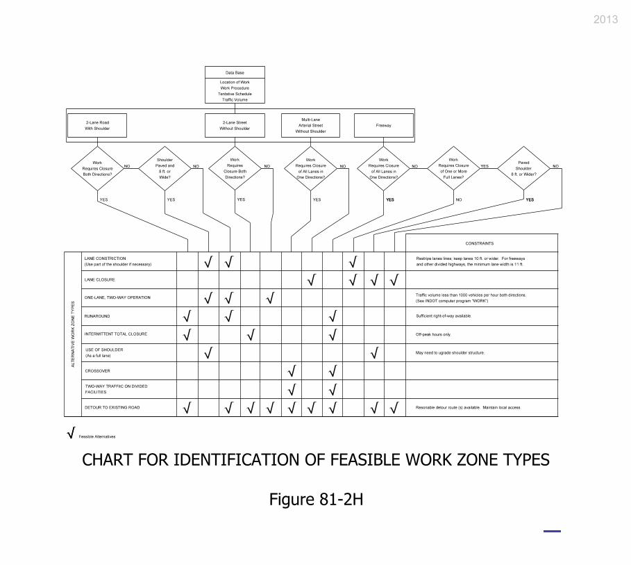
2013

2013

2013

2013

INCENTIVE / DISINCENTIVE (I/D) AMOUNT DETERMINATION English-Units Project
I. PROJECT CHARACTERISTICS
Route Contract No. Project No. Des. No. District: National Highway System (NHS) Route? Yes No Location: Estimated Start Date of Work: Estimated Completion Date Without I/D: Estimated Contract Amount: $ * Estimated Local-Traffic AADT: Trucks % * Estimated Through-Traffic AADT: Trucks % ** Length of Local-Traffic Detour: mi ** Length of Through-Traffic Detour: mi
* Use best judgment for breakdown of traffic. ** Use official detour for through traffic.
II. I/D CONSIDERATIONS
Contract restrictions (e.g., utility adjustments, R/W acquisitions, permits, environmental constraints, closure times, special fabrication requirements):
Reasons for proposing I/D:
Critical construction elements:
Estimated Completion Date With I/D: Estimated I/D Amount: $ per day Proposed I/D Time: Calendar Days
Maximum I/D Adjustments = (I/D Amount) x (I/D Time):
$ x days = $
2013

User Vehicle Costs (UVC): $0.25 / mi / veh (Autos & Trucks) User Time Value (UTV): $5.00 / h / veh Local Design Speed: mph Through Design Speed: mph Traffic Adjustment Factor (TAF): Suggested Value 0.35
(TAF normal range is 0.30 to 0.45)
NOTE: Use either of the following analyses depending on the type of project (road closure-detoured or through-traffic project). Various computer programs are available such as QUEWZ for estimating queue lengths and user costs that can be used in lieu of the following for freeway work-zone lane closures. Contact the Highway Operations Division’s Traffic Control Team for details.
A. User Costs for Closure-Detoured Project
Local Traffic:
Vehicle Costs = (UVC) (AADT) (Local-Detour Length)
($0.25) ( ) ( mi) = $
User Costs = (UTV) (AADT) (Local-Detour Length) (1/Design Speed) ($5.00) ( ) ( mi) (1/ ) = $
Local-Road User Costs (LRUC) = (Vehicle Costs + User Costs)
$ + $ = $
Through Traffic:
Vehicle Costs = (UVC) (AADT) (Through-Detour Length) ($0.25) ( ) ( mi) = $
User Costs = (UTV) (AADT) (Through-Detour Length) (1/Design Speed)
($5.00) ( ) ( mi) (1/ ) = $ Through-Road User Costs (TRUC) = (Vehicle Costs + User Costs)
$ + $ = $
Site RUC = LRUC + TRUC $ + $ = $
2013

B. Disruption Costs for Through-Traffic Project
NOTE: The following analysis provides delay cost for through traffic only. If
the project includes ramp or intersection closures, the analysis from Part A above can be added to the through-traffic disruption costs or other factors commensurate upon the scope of the particular project.
Vehicle Costs = (UVC) (AADT) (TAF)
($0.25) ( ) ( ) = $
User Costs = (UTV) (AADT) (TAF) ($5.00) ( ) ( ) = $
Traffic Disruption Costs = (Vehicle Costs + User Costs)
$ + $ = $
C. General Comments
D. Other Factors to Consider. Is the route on or near one or more of the following?
School: Yes No Hazardous-Materials Route: Yes No Hospital: Yes No Special or Seasonal Event: Yes No Emergency Route: Yes No Local Business: Yes No
III. SUMMARY
Recommended Maximum I/D Time: Calendar Days Recommended I/D Date: Recommended Maximum I/D Amount: $ per Day Is I/D amount > 5% of contract amount? Yes No
NOTE: If the I/D amount per day is greater than the Site RUC or Traffic User Costs, I/D
is not justified. IV. APPROVALS
2013

A. Non-NHS Project
Prepared By: Date
Recommended By: ____________________________ Date __________ Field Construction Engineer, Construction Mgmt.. Div.
If I/D ≤ 5% of contract amount,
Approved By: ____________________________ Date __________
Director, Construction Management Division
If I/D > 5% of contract amount, Approved By: ____________________________ Date __________
Chief Highway Engineer
Received By: ____________________________ Date __________ Contracting Office Manager, Contract Administration Division
2013

B. NHS Project
Prepared By: Date
Recommended By: ____________________________ Date __________ Field Construction Engineer, Construction Mgmt.. Div.
Approved By: ____________________________ Date __________
Chief Highway Engineer
Received By: ____________________________ Date __________ Contracting Office Manager, Contract Administration Division
NHS Exemption: Yes No
If No, this document must be submitted to FHWA for approval. Approved By: ____________________________ Date __________
Federal Highway Administration
2013

INDIANA DEPARTMENT OF TRANSPORTATION—2013 DESIGN MANUAL
CHAPTER 82
Traffic-Control-Plan Design
Design
Memorandum Revision
Date Sections Affected
13-01 Jan. 2013 Figure 82-6B, Figure 82-6C 13-03 Feb. 2013 82-6.03
NOTE: This chapter is currently being re-written and its content will be included in Chapter 503 in the future.

Page 2 2013 Indiana Design Manual, Ch. 82
TABLE OF CONTENTS
LIST OF FIGURES ......................................................................................................................... 3
82-1.0 PRELIMINARY ENGINEERING ..................................................................................... 4
82-1.01 Responsibilities............................................................................................................. 4
82-1.02 District Input ................................................................................................................. 5
82-1.03 Engineer’s Report ......................................................................................................... 5
82-2.0 TRAFFIC-CONTROL-PLAN DEVELOPMENT .............................................................. 7
82-2.01 Responsibilities............................................................................................................. 7
82-2.02 Plan Development ........................................................................................................ 8
82-2.03 Traffic-Control Plan Content ...................................................................................... 10
82-2.04 Design Considerations ................................................................................................ 12
82-2.04(01) Engineering ...................................................................................................... 12
82-2.04(02) Constructability ................................................................................................ 13
82-2.04(03) Construction Design ......................................................................................... 13
82-2.04(04) Economic or Business Impact .......................................................................... 14
82-2.04(05) Pedestrians and Bicyclists ................................................................................ 14
82-3.0 GEOMETRIC DESIGN ................................................................................................... 15
82-3.01 Construction-Zone Design Speed ............................................................................... 15
82-3.02 Lane or Shoulder Width ............................................................................................. 16
82-3.03 Transition Taper Rate ................................................................................................. 17
82-3.04 Sight Distance ............................................................................................................. 17
82-3.05 Horizontal Curvature .................................................................................................. 18
82-3.06 Vertical Curvature ...................................................................................................... 19
82-3.07 Cut or Fill Slope ......................................................................................................... 19
82-3.08 Maximum Grade ......................................................................................................... 19
82-3.09 Through-Lane Cross Slope ......................................................................................... 19
82-3.10 Vertical Clearances ..................................................................................................... 20
82-4.0 ROADSIDE SAFETY ...................................................................................................... 20
82-4.01 Positive Protection ...................................................................................................... 20
82-4.02 Appurtenance Type ..................................................................................................... 21
82-4.02(01) Guardrail .......................................................................................................... 22
82-4.02(02) Temporary Traffic Barrier (TTB) ..................................................................... 22
82-4.02(03) End Treatment or Impact Attenuator ............................................................... 24
82-4.03 Design/Layout ............................................................................................................. 25
82-4.04 Pavement Edge Dropoff on Multilane Divided Highway .......................................... 25
82-5.0 HIGHWAY CAPACITY .................................................................................................. 27

2013 Indiana Design Manual, Ch. 82 Page 3
82-5.01 Traffic-Capacity Analysis .......................................................................................... 27 82-5.02 Queuing Analysis ....................................................................................................... 27
82-6.0 APPLICATIONS .............................................................................................................. 28 82-6.01 Lane or Shoulder Closure ........................................................................................... 28 82-6.02 Two-Way Traffic on a Divided Highway .................................................................. 30 82-6.03 Interstate Highways Congestion Policy [Rev. Feb. 2012] ......................................... 32 82-6.04 Runaround or Detour .................................................................................................. 32
FIGURES ...................................................................................................................................... 35 LIST OF FIGURES Figure Title 82-2A Participants During Traffic Control Plan Development 82-2B Editable Traffic Maintenance Memorandum to District 82-3A Minimum Radii for Horizontal Curves (Construction Zones) 82-3B K-Values for Sag Vertical Curves (Comfort Criteria in Construction Zones) 82-4A Flare Rates for Temporary Concrete Median Barrier (Construction Zones) 82-4B Clear Zone Distances (ft) (Construction Projects) 82-6A Lane Closures on Bridges 82-6B Interstate Lane Closure Policy – Statewide [Del. Feb. 2013] 82-6C Interstate Lane Closure Policy – Selected Urban Areas [Del. Feb. 2013] 82-7A Editable Traffic Control Plans Checklist
Page 4 2013 Indiana Design Manual, Ch. 82
CHAPTER 82
TRAFFIC-CONTROL-PLAN DESIGN To some extent, highway construction disrupts the normal flow of traffic and poses safety hazards to motorists, bicyclists, pedestrians and workers. Therefore, to alleviate potential operational and safety problems, INDOT requires that work-zone traffic control be considered on each highway construction project. The work-zone traffic-control plan may range in scope from very detailed plans, incorporation of unique or recurring special provisions, or to merely referencing the INDOT
Standard Drawings, Standard Specifications, or Manual on Uniform Traffic Control Devices
(MUTCD). This Chapter provides the necessary information to develop a well-conceived work-zone traffic-control plan that minimizes the adverse effects of traffic disruption and hazards. 82-1.0 PRELIMINARY ENGINEERING 82-1.01 Responsibilities The Office of Environmental Services’ Environmental Policy Team is responsible for initially addressing work-zone traffic control. This information is to be included in the Engineer’s Report. In determining the initial work-zone traffic control, the Environmental Policy Team will perform the following: 1. collect all necessary data (e.g. traffic counts, accident history, roadway geometrics, proposed
development, operating speeds); 2. coordinate planning and scoping meetings with the applicable participants (e.g., designer,
Office of Traffic Engineering, district Office of Design, Highway Operations Division, local officials);
3. conduct analyses (e.g., capacity analyses, traffic impact studies, safety studies, queuing
analysis); 4. review design alternates; 5. review traffic-control alternates (e.g., detour, crossovers, runaround, lane closure). The
preferred plan will be incorporated into the Report;

2013 Indiana Design Manual, Ch. 82 Page 5
6. estimate the construction cost and economic impact of various options and improvements;
7. coordinate funding and timing with other projects within the corridor; and
8. if required, form a transportation-management-plan team and include the team’srecommendations in the Report. Chapter 81 provides information on the development of aTMP.
82-1.02 District Input
During the development of the Engineer’s Report, the Environmental Policy Team will obtain the following information from the district.
1. The district’s concurrence in the selected traffic-control alternate;2. detour-route location and additional travel distance;3. traffic projections anticipated to use detour;4. anticipated delays to fire, police, emergency-medical, or postal service;5. number of school buses using facility (additional delay and distance); and6. local roads which may be used for official or unofficial detour.
82-1.03 Engineer’s Report
The Environmental Policy Team will be responsible for incorporating the proposed work-zone traffic control plan in the Engineer’s Report and ensuring that the following have been considered.
1. Traffic-Control Alternates. The Report will address the work-zone traffic-controlinformation as follows:
a. Applicability of INDOT Standard Drawings;b. alternate traffic-control strategies;c. alternate detour types and locations;d. construction scheduling and phasing requirements;e. alternate geometric design features;f. estimated costs for alternate traffic-control strategies; andg. special requirements of the work-zone traffic control.

Page 6 2013 Indiana Design Manual, Ch. 82
2. Construction Operation Selection. The construction applications which may be considered are as follows:
a. work beyond the shoulder; b. shoulder work and partial lane closure; c. lane closure for a 2-lane highway; d. single-lane closure for a 4-lane highway; e. two-way traffic on a divided highway; f. work within or near an intersection; g. offset alignments; and h. official or local detour (e.g., runaround, crossovers).
Chapter 81 provides additional guidance for determining which of these construction applications may be appropriate.
3. Detour Location. The use of a detour (e.g., runaround, crossovers, alternate route) should be
determined on a project-by-project basis. The detour location should be in accordance with the following:
a. minimize impacts to adjacent developments (e.g., site access); b. minimize the magnitude and cost of utility relocations; c. minimize environmental impacts; and d. be offset a sufficient distance so that it will not interfere with construction.
The Department may be required to repair local highways that may be damaged while being used as unofficial detour routes. See the INDOT Detour Policy for additional information. Investigations, details, and agreements with local officials may be required in subsequent phases.
4. Community Impact. The Report should address the impacts on neighborhoods, parks,
schools, businesses, etc. A detour can significantly increase traffic through a community such that local traffic can no longer use the detour route. The Report should also address how the work-zone traffic control will affect fire, ambulance, police, and school-bus routes.
5. Interest Groups. The Report should address the concerns of local governments, agencies,
public officials, or special interest groups (e.g., homeowner associations). If reasonable, changes should be made to the work-zone traffic control to address their concerns. Working with local officials and organizations early in project development can significantly reduce opposition to, or create support for, a project by addressing local concerns.

2013 Indiana Design Manual, Ch. 82 Page 7
6. Transportation-Management Plan. Where a project does not warrant the development of a Transportation Management Plan (TMP), the Environmental Policy Team should still review Chapter 81 for applicable guidelines and criteria that should be discussed during this phase. The conclusion of this phase should result in a reasonable traffic-control strategy for the project.
82-2.0 TRAFFIC-CONTROL-PLAN DEVELOPMENT 82-2.01 Responsibilities It is the designer’s responsibility to ensure that an adequate traffic-control plan (TCP) is developed. If the traffic-control requirements are not entirely included in the INDOT Standard Drawings or Standard Specifications, the designer should prepare a TCP that will adequately address all required non-standard traffic-control work for the project. The designer will be responsible for the following. 1. reviewing the information in the Engineer’s Report or, if not available, contacting the
appropriate entity or agency (e.g., traffic-design, FHWA) to obtain the necessary information; 2. evaluating the proposed design alternates (e.g., detour, crossovers, runaround, lane closure);
see Chapter 81; 3. developing the geometric design for a specially-constructed detour (e.g., crossovers,
runaround, offset alignment); see Section 82-3.0; 4. addressing the roadside-safety concerns within the construction zone (e.g., construction clear
zone, temporary concrete barrier); see Section 82-4.0; 5. selecting and locating the required traffic control devices (e.g., pavement markings,
barricades, signs); see Chapter 83; 6. developing and evaluating alternate construction sequences; 7. performing the necessary capacity and queuing analyses, if not already provided; 8. making a written request to the Office of Pavement Engineering regarding use of a shoulder
or a portion of it for traffic maintenance. A copy of the request should be sent to the project manager. The request should include the construction-year AADT, percent trucks of AADT, and the approximate duration of traffic’s shoulder use;

Page 8 2013 Indiana Design Manual, Ch. 82
9. ensuring that the proposed traffic-control plan is discussed and reviewed during the Preliminary Field Check; and
10. coordinating with public-information officials to inform the public of proposed road closure,
detour route, etc. 82-2.02 Plan Development The TCP should be developed through the phases described below before it can be incorporated into the contract and approved for letting. The following describes the development of the TCP at each project phase. 1. Engineer’s Report. The Environmental Policy Team will be responsible for determining the
initial work-zone traffic control strategies to be used on the project. These should be shown in the Engineer’s Report. If changes are made to the recommendations in the Report, the designer should notify the Environmental Policy Team of these changes.
2. Structure Type and Size (Bridge-Replacement Project) or Grade Review (Sight-Distance
Improvement or Small Structure Replacement. At this plan development stage, the designer is responsible for contacting the appropriate district to obtain its input regarding traffic maintenance. Figure 82-2B is a blank memorandum copy which the designer should download, fill in the project information blanks, then transmit to the district. An editable version of this form may also be found on the Department’s website at www.in.gov/dot/div/contracts/design/dmforms/. District input should be solicited if a TCP is specified in the Engineer’s Report. The district should provide the requested information to the designer.
3. Preliminary Field Check. During the Preliminary Field Check, review the proposed traffic-
control strategy against actual and anticipated field conditions and be prepared to perform the following tasks.
a. drive the local detour;
b. determine the environmental effects of a crossover or runaround;
c. estimate the extent and cost of property damage caused by a crossover or runaround,
including additional right-of-way requirements and costs;

2013 Indiana Design Manual, Ch. 82 Page 9
d. determine the feasibility of maintaining traffic on the facility (e.g., roadway, bridge) while work is in progress;
e. evaluate the need for scheduling work activities to avoid traffic delays during peak
commute hours or local events;
f. determine the effects on project constructability; and
g. review the physical and operational elements of the TCP with other projects in the area to ensure that there are no conflicts with the proposed TCP.
At the conclusion of this phase, the preliminary geometric design, safety, and capacity analyses should be completed, and suggested plan modifications evaluated and reviewed. The designer should determine the proposed location of all traffic-control elements and special design elements (e.g., runaround, crossovers) and should establish the proposed construction phasing. The designer should contact the district for its input, even if the proposed TCP is recommended in the Engineer’s Report.
4. Hearing. The plan and profile, cross-sections, construction schedule and phasing, and impact
reports should be completed at this stage. Begin preparation of the required special provisions and the permit process. Prepare an estimate of the time required to re-open the facility (e.g., roadway, bridge) to traffic after construction starts.
5. Final Field Check. Review all issues emerging from the hearing stage and complete
subsequent plan modifications. Review the project’s physical and operational elements of the TCP with other projects in the area to ensure that there are no conflicts with the proposed TCP. Examples include detouring traffic onto a local road which is scheduled for reconstruction during the same time period, or closing a highly-traveled highway during special events or seasons. Coordinate with the Office of Communications so that they can begin to inform the public of road closures or alternate detour routes.
6. District Construction Engineer Review. After design approval, the designer should submit
the proposed TCP to the district construction engineer. The district construction engineer will provide written comments or concurrence regarding the proposed TCP to the designer, with a copy to the appropriate Production Management Division office manager. The office manager will provide written comments or concurrence regarding the proposed TCP to the designer. If necessary, the designer will revise the proposed TCP until both district construction engineer and office manager concur.

Page 10 2013 Indiana Design Manual, Ch. 82
7. Final Plans Review. Determine and check all quantity estimates. Complete the detail drawings and include all relevant special provisions in the contract documents. Do not show unofficial detour routes in the plans or special provisions.
The Department requires a coordinated team effort to develop and successfully implement a TCP. Figure 82-2A lists the participants involved in each phase of its development. 82-2.03 Traffic-Control Plan Content The type and size of a project greatly impacts the amount of information required in the TCP. For example, for a traffic-signs project, the TCP may only be a listing of the appropriate INDOT Standard Drawings. However, for a freeway reconstruction project, the TCP may include full-size drawings, special details, special provisions, special task forces, etc. The TCP content will be determined on a project-by-project basis. The TCP may include the following. 1. Construction Plan Sheets. A reconstruction project will require detailed plans for
accommodating traffic at each construction stage (e.g., specially-built detour, crossovers, staged construction). These plans may include geometric layout details, positive-protection strategies, the traffic-control devices, etc. A smaller project (i.e., partial 3R, traffic signs, signals, or a spot improvement) will rarely require this level of detail. Chapters 14 and 15 provide the Department’s plans-preparation criteria (e.g., sheet sizes, scales, line weights, CADD symbols) which are also applicable to a TCP. The INDOT Typical Plan Sheets
document provides traffic-maintenance detail sheet examples.
A traffic-maintenance plan that requires at least one shoulder to carry traffic on a temporary basis during construction should include information regarding shoulder-corrugation installation requirements. A note should be included that reads, ―Corrugations shall not be milled into the _____ shoulder between Sta. _____ and Sta. _____ until after traffic is no longer temporarily using the shoulder.‖
2. Special Provisions. Special provisions are used to explain special procedures, materials, or
equipment used in the TCP that are not addressed in the INDOT Standard Specifications. The TCP may only consist of special provisions. Prior to developing a new special provision, the designer should first ensure that its requirements do not already appear in the INDOT Standard Specifications or recurring special provisions. Chapter 19 provides information on the requirements for preparing a special provision.
3. Traffic-Control Devices. Include a complete listing of the traffic-control devices required to
direct traffic through the work zone in the TCP. This may include the number of drums,

2013 Indiana Design Manual, Ch. 82 Page 11
barricades, cones, signs, temporary pavement markings, warning lights, flashing-arrow signs or other devices required to implement the construction. Chapter 17 provides the Department’s criteria for determining plan quantities.
4. Construction Sequence and Time. The TCP should include a proposed construction
sequence. 5. Work Schedule. A special provision should identify restricted work schedules which the
contractor will be required to follow (e.g., no construction work during specified hours or days).
6. Telephone Numbers. A special provision should require the contractor to provide names and
telephone numbers of the contractor’s superintendent and one other responsible employee. 7. Permits. For restricted-lane width, the district Office of Construction will be responsible for
coordinating with the Planning Division’s Office of Roadway Safety and Mobility after the contract is let to obtain the necessary permits to allow oversize vehicles through the work zone.
8. Agreement or Legal Release. An agreement or legal release may be required before INDOT
can use a local facility as a detour route. The designer should initiate this process early in the design of the work-zone traffic control.
9. Media. The designer should inform the Office of Communications as to when and where
there will be a major road or ramp closure or detour. 10. Pedestrians and Bicyclists. The TCP should address the safe accommodation of pedestrians
and bicyclists through the work area. Construction phasing may need to be scheduled around non-peak pedestrian-traffic times.
11. Local Businesses and Residents. Maintain at least one reasonable access to each site of
business establishment or residency. The designer should also ensure that these entities are kept informed of planned street, ramp or driveway closures.
12. Emergency Vehicles. The TCP should address the safe and efficient accommodation of
emergency vehicles through the construction area. 13. Checklist. Section 82-7.0 provides a checklist which should be reviewed to ensure that all
applicable work-zone traffic-control elements have been addressed in the TCP.

Page 12 2013 Indiana Design Manual, Ch. 82
82-2.04 Design Considerations The objective of the TCP is to provide an implementation strategy that will minimize the adverse effects of traffic disruption on motorists, pedestrians, bicyclists, or workers. Therefore, the designer should consider the following design considerations when developing the TCP. For a more in-depth analysis of these elements, the designer should review Chapter 81. 82-2.04(01) Engineering
The designer should consider the following engineering elements in developing the TCP. 1. Geometrics. The TCP should provide adequate facilities for a motorist to safely maneuver
through the construction area, day or night. The design should avoid frequent and abrupt changes in roadway geometrics, such as lane narrowing, a lane drop, or a transition which requires a rapid maneuver. Section 82-3.0 provides geometric design criteria for a construction zone.
2. Roadside Safety. Motorist, pedestrian, bicyclist, and worker safety is a priority element of a
TCP and should be an integral part of each phase of the construction project (i.e., planning, design, and construction). Section 82-4.0 addresses the roadside-safety issues which are encountered during construction.
3. Highway Capacity. The TCP should, where practical, provide the capacity necessary to
maintain an acceptable level-of-service for the traveling public. This may require converting a shoulder to a travel lane, eliminating on-street parking, constructing a temporary lane, opening additional lanes during peak traffic-volume periods, or expanding public transportation. Section 82-5.0 provides further information on highway-capacity issues.
4. Traffic-Control Devices. Traffic-control devices should be included in the TCP to safely
direct vehicles through or around the construction zone. Chapter 83 provides guidance on the selection and location of traffic-control devices.
5. Overhead Lighting. The design should maintain existing overhead lighting and consider the
need for supplemental roadway lighting at a potentially hazardous site within the work area. Chapter 83 discusses the use of construction-zone lighting.

2013 Indiana Design Manual, Ch. 82 Page 13
82-2.04(02) Constructability
The designer should evaluate the construction sequence to identify safety, operational, or logistical problems and to facilitate the timely completion of the project. Some of the elements which should be evaluated include the following: 1. the maneuverability of traffic through horizontal or vertical alignments during all
construction phases; 2. the separation of opposing traffic, workers, equipment, or other hazards; 3. the work area which will be used for equipment maneuverability; and 4. the access points to work sites or material-storage sites.
** PRACTICE POINTER **
Adequate working space between the traffic and the work area
should be provided. This applies especially where construction is phased or if the project includes a temporary runaround.
82-2.04(03) Construction Design
Available construction options that may improve the TCP include the following: 1. the use of special materials (e.g., quick-curing concrete that can support vehicular loads
within hours after pouring); 2. the use of special designs (e.g., using a precast box structure instead of a bridge or cast-in-
place box structure); 3. scheduling requirements which will reduce traffic disruptions (e.g., working at night and
during off-peak traffic-volume hours); 4. project phasing which will allow traffic to use the facility prior to project completion; or

Page 14 2013 Indiana Design Manual, Ch. 82
5. contractor cost incentives/disincentive for early or late completion of construction for a facility with a high AADT. For a project with FHWA oversight, a contractor incentive is subject to approval by the FHWA.
Chapter 81 provides additional information on construction alternates. 82-2.04(04) Economic or Business Impact
The designer should consider the economic impacts a TCP may have on road users, adjacent businesses, or residential developments. The designer should consider the following: 1. vehicular travel time; 2. fuel consumption; 3. vehicular wear; 4. air pollution; 5. access to residential developments; 6. patron access to businesses (e.g., restaurants, gas stations, stores); 7. employee or delivery access to commercial developments; and 8. shipments to manufacturing companies. The designer should also review the TCP to ensure that it does not restrict access to businesses during peak retail shopping periods. For example, a road closure should not be made in the vicinity of a regional retail mall during the period from Thanksgiving to Christmas. Coordination with local businesses, developers, or other land owners should be made early in the development of the TCP. At least one access should be maintained to each development throughout the contract time. 82-2.04(05) Pedestrians and Bicyclists
Address the safe accommodation of pedestrians or bicyclists through the construction zone early in project development. Locations that would warrant pedestrian or bicyclist considerations include the following: 1. where a sidewalk traverses the work zone; 2. where a designated school route traverses the work zone; 3. where significant pedestrian or bicyclist activity or evidence of such activity exists; or

2013 Indiana Design Manual, Ch. 82 Page 15
4. where existing land use generates such activity (e.g., park, school, shop). The considerations to be made in addressing pedestrian or bicyclist accommodation through a construction zone are as follows: 1. physical separation of pedestrians and vehicles where practical; 2. providing temporary lighting for each walkway that is currently lighted; 3. directing pedestrians or bicyclists to a safe location (e.g., the other side of a street) where a
pedestrian walkway or bicycle path cannot be provided; 4. staging construction operations such that if there are two walkways they are both not out of
service at the same time; 5. planning the construction such that temporary removal of a sidewalk will occur in the
shortest practical time or is scheduled around non-peak pedestrian traffic-volume times; or 6. for information on handicapped-accessibility criteria, see Section 51-1.0. 82-3.0 GEOMETRIC DESIGN The following provides design criteria which apply to temporary crossovers on a divided highway, an existing roadway through a construction zone, or a detour specifically designed for construction project (e.g., crossovers, runaround). These criteria do not apply to a detour over existing routes. 82-3.01 Construction-Zone Design Speed The construction-zone design speed applies to the design of the geometric elements through the work zone. It does not apply to the regulations that are used for posting the speed limit through the work zone. Regulatory speed limit is discussed in Section 83-2.03. In selecting the construction-zone design speed, the designer should consider the following. 1. Posted Speed Limit. The construction zone design speed should take into account the
following:
a. the posted speed limit of the facility immediately prior to the work zone;

Page 16 2013 Indiana Design Manual, Ch. 82
b. the anticipated posted work-zone speed limit through the work zone (see Section 83-2.03); and
c. the posted speed limit of the facility before construction begins. The construction-zone design speed should not be more than 10 mph lower than the posted speed limitprior to construction.
2. Urban or Rural Area. The construction-zone design speed in a rural area should be higherthan that in an urban area. This is consistent with the fewer constraints in a rural area (e.g.,less development).
3. Terrain. A lower construction-zone design speed may be applicable to a rolling terrain. Thisis consistent with the higher construction costs as the terrain becomes more rugged.
4. Traffic Volume. The construction-zone design speed may vary according to the trafficvolume. Therefore, consider a higher design speed as traffic volume increases.
The designer should work with the appropriate district traffic engineer to establish the construction-zone design speed for an INDOT route, or a local public agency’s representative for a local-agency route. The designer should show the construction-zone design speed on the first sheet of the TCP.
If crossovers are used to maintain one lane of traffic in each direction on a rural Interstate route, the following will apply.
1. Use temporary concrete median barrier.
2. Unless the median shoulder is full depth, it is to be removed and replaced with a 6-ft widthsection with its pavement design to be requested by the designer.
3. The traffic maintenance should be as shown in Figure 81-3A(0).
4. Shoulder corrugations are to be milled into the new shoulder after traffic is crossed over tothe other side.
82-3.02 Lane or Shoulder Width
There should not be a reduction in the roadway-cross-section width through the construction zone. However, this may not be practical. Section 83-3.02 provides the minimum taper rate that should be

2013 Indiana Design Manual, Ch. 82 Page 17
used on an approach to a lane-width reduction. The following lane and shoulder widths should be used in a construction zone. 1. Divided Highway. For a freeway or other divided highway, maintain a minimum 11-ft lane
width with shoulders of 2 ft or wider. Under restrictive conditions, however, the designer may consider a 10-ft lane width if an alternate route is provided for wide vehicles.
2. Undivided Highway. Maintain a minimum 10-ft lane width and 1-ft shoulder width. 3. Runaround. Design a runaround with 12-ft lane width and 6-ft shoulder width. 4. Temporary Crossover. For 1-lane, one-way operations, the lane width should be 16 ft with 5-
ft shoulder widths. For a multi-lane or multi-directional operation, each lane width should be 12 ft with 5-ft shoulder widths.
82-3.03 Transition Taper Rate A lane closure, lane-width reduction, or lane shift requires the use of a transition taper to safely maneuver traffic around the encroaching restriction. Section 83-3.02 provides the minimum taper length for each taper application in a construction zone (e.g., lane closure, lane shift). Use the construction-zone design speed in selecting the appropriate taper rate from Section 83-3.02. 82-3.04 Sight Distance For the approach to the first physical indication of the construction zone, the sight distance available to the motorist should be based on the decision-sight-distance criteria provided in Section 42-2.0 and, at a minimum, based on the stopping-sight-distance criteria provided in Section 42-1.0. Through the construction zone itself, the designer should ensure that at least the minimum stopping sight distance is available to the motorist. Unfortunately, the locations of many design features are often dictated by construction operations. However, an element may have an optional location. For example, a lane closure or transition should be located where the approaching motorist has decision sight distance available to the lane closure on transition. Throughout a horizontal curve in the construction area, the designer should check the horizontal clearance (i.e., the middle ordinate) of the horizontal curve using its radius and the minimum stopping sight distance for the construction-zone design speed (see Section 43-4.0). Figure 43-4B provides the horizontal-clearance criteria for each combination of minimum stopping sight distance and curve radius. The designer should also consider the percentage of trucks and other heavy vehicles in determining the controlling sight distance.

Page 18 2013 Indiana Design Manual, Ch. 82
Computations must be submitted for horizontal stopping sight distance at the Grade Review or Structure Type and Size stage, or the next plan submission if the project is already beyond the Grade Review or Structure Type and Size stage, for a temporary runaround or other traffic-maintenance means. A statement that a temporary runaround is in accordance with the INDOT Standard
Drawings is not sufficient to verify that adequate horizontal-alignment stopping sight distance is provided. Computations must be submitted for intersection sight distance for each traffic-maintenance phase. 82-3.05 Horizontal Curvature Design the horizontal curvature using the selected construction-zone design speed. Use AASHTO Method 2 for distributing superelevation and side friction to determine the radius and superelevation rate of the horizontal curve. In this method, superelevation is introduced only after the maximum allowable side friction has been reached. If compared to AASHTO Method 5, this approach results in no superelevation on a flatter curve (i.e., maintaining the normal crown through the curve) and a reduced rate of superelevation on a sharper curve. Figure 82-3A, Minimum Radius for Horizontal Curve in Construction Zones, provides the minimum radius (including the radius for retention of the normal crown section) for a horizontal curve through a construction zone based on AASHTO Method 2. For other horizontal-curvature elements (e.g., superelevation transition length), the criteria described in Chapter 43 is also applicable to a construction zone. Where it is necessary to use the shoulder as a travel lane, the shoulder cross slope may be a concern on a horizontal curve (i.e., the slope may be in opposite direction than the superelevated section). One or more of the following options may be considered to alleviate this problem. 1. Rebuild the shoulder so that it has the proper superelevation rate based on the selected
construction-zone design speed. 2. Install an advisory-speed plate for the horizontal curve, 3. Install buzz strips in conjunction with Item 2 above in advance of the temporary travel lane
(see Figure 82-4A, Flare Rate for Temporary Concrete Median Barrier. 4. Prohibit trucks or other large vehicles from using the temporary travel lane. 5. Detour such large vehicles to other facilities.

2013 Indiana Design Manual, Ch. 82 Page 19
82-3.06 Vertical Curvature Design a sag vertical curve using the selected construction-zone design speed and the comfort criterion provided in Figure 82-3B. The comfort criterion is based on the comfort effect of change in vertical direction through a sag vertical curve because of the combined gravitational and centrifugal forces. The ride through a sag vertical curve is considered comfortable if the centripetal acceleration does not exceed 1 ft2. 82-3.07 Cut or Fill Slope Design a temporary cut or fill slope to satisfy the design criteria shown in Chapter 53 and Section 45-3.0. However, a 3:1 fill slope may be used where there is sufficient clear-zone width available at the bottom of the slope (see Section 82-4.04). The use of a steeper fill slope may be considered, but it may require the installation of a roadside barrier. Although a detour rarely involves excavation, a 3:1 cut slope is acceptable in place of the flatter slope required in Chapter 53. The use of a slope steeper than 3:1 for a cut depth of less than 10 ft may be acceptable under restrictive conditions. The anticipated traffic volume and the length of time that the detour will be in place should be considered in determining the final cut or fill slope. Stable embankment material must be used and placed in accordance with the INDOT Standard Specifications. Drainage should be considered between the work zone and the traffic in establishing the phases of construction. 82-3.08 Maximum Grade The vertical grade should be designed using the 3R criteria for the appropriate functional classification, rural or urban environment, and construction-zone design speed. 82-3.09 Through-Lane Cross Slope The 3R criteria should be used for the appropriate functional classification and rural or urban environment. If the existing shoulder is used for through traffic, a 4% cross slope will be acceptable.
Page 20 2013 Indiana Design Manual, Ch. 82
82-3.10 Vertical Clearances The 3R criteria should be used for the appropriate functional classification and rural or urban environment. If the design for a temporary runaround or other traffic-maintenance consideration excluding a detour over existing roads is not in accordance with the criteria for Level One elements, a design exception will be required. 82-4.0 ROADSIDE SAFETY Through a construction zone, a motorist is often exposed to numerous hazards (e.g., restrictive geometrics, construction equipment, opposing traffic). A complete elimination of construction-zone hazards is impractical. A motorist’s exposure to potential hazards should be reduced. The following lists roadside-safety criteria which apply only to the roadside elements within the construction zone. These criteria do not apply to a detour over existing routes. 82-4.01 Positive Protection The designer should consider a traffic-control method which does not require the use of positive protection, minimizes the hazard exposure, or maximizes the separation of workers and traffic. However, positive protection is often required. Positive-protection devices should be considered in each work-zone situation that places workers at increased risk from motorized traffic, and where positive-protection devices offer the highest potential for increased safety for workers and road users. The decision regarding the use of positive protection is to be documented and placed in the project file. Locations where positive protection should be considered include the following: 1. exposed end of temporary concrete barrier; 2. untreated guardrail end in a 2-way, 2-lane operation; 3. bridge pier; 4. bridge-railing end; 5. structure foundation (e.g., bridge falsework, sign foundation); 6. excavation or rock cut; 7. gap in median between dual bridges; 8. pavement edge or shoulder dropoff in excess of 12 in.; or
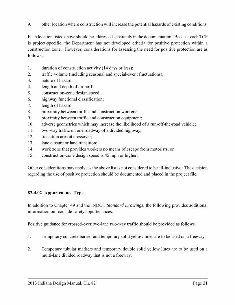
2013 Indiana Design Manual, Ch. 82 Page 21
9. other location where construction will increase the potential hazards of existing conditions. Each location listed above should be addressed separately in the documentation. Because each TCP is project-specific, the Department has not developed criteria for positive protection within a construction zone. However, considerations for assessing the need for positive protection are as follows: 1. duration of construction activity (14 days or less); 2. traffic volume (including seasonal and special-event fluctuations); 3. nature of hazard; 4. length and depth of dropoff; 5. construction-zone design speed; 6. highway functional classification; 7. length of hazard; 8. proximity between traffic and construction workers; 9. proximity between traffic and construction equipment; 10. adverse geometrics which may increase the likelihood of a run-off-the-road vehicle; 11. two-way traffic on one roadway of a divided highway; 12. transition area at crossover; 13. lane closure or lane transition; 14. work zone that provides workers no means of escape from motorists; or 15. construction-zone design speed is 45 mph or higher. Other considerations may apply, as the above list is not considered to be all-inclusive. The decision regarding the use of positive protection should be documented and placed in the project file. 82-4.02 Appurtenance Type In addition to Chapter 49 and the INDOT Standard Drawings, the following provides additional information on roadside-safety appurtenances. Positive guidance for crossed-over two-lane two-way traffic should be provided as follows. 1. Temporary concrete barrier and temporary solid yellow lines are to be used on a freeway. 2. Temporary tubular markers and temporary double solid yellow lines are to be used on a
multi-lane divided roadway that is not a freeway.

Page 22 2013 Indiana Design Manual, Ch. 82
3. Temporary double solid yellow lines are to be used on an urban or rural multi-lane undividedroadway.
Temporary asphalt divider is not to be used for separating traffic.
82-4.02(01) Guardrail
A temporary guardrail installation for an Interstate-route project should be in accordance with the permanent installation criteria described in Chapter 49 and the INDOT Standard Drawings, except as shown in Figure 82-4B, Work-Zone Clear-Zone Width (ft). For short-term construction, the installation of new temporary guardrail is not practical.
The following should be used to determine the temporary guardrail length at each corner of a temporary bridge in a two-lane runaround. For a construction-zone design speed of 45 mph or lower, the minimum guardrail length is 50 ft. For a construction-zone design speed of 50 mph or higher, the minimum guardrail length is 100 ft.
A temporary guardrail run should continue until the guardrail warrant for an embankment as shown in Section 49-4.02 is satisfied. The design speed, and not the construction-zone design speed, should be used to determine the guardrail warrant for an embankment.
82-4.02(02) Temporary Traffic Barrier (TTB)
A TTB is used to provide protection to the motorist and the workers in the work zone. The primary functions of TTB are as follows:
1. to separate two-way traffic;2. to protect workers and pedestrians;3. to keep traffic from entering a work area (e.g., excavation, storage site); and4. to protect construction elements (e.g., bridge falsework, exposed objects).
1. Types of TTB.
a. Type 1. This type is used only to separate two-way traffic.
b. Type 2. This type is used to separate traffic from the work zone. It should be used toprotect traffic from an obstruction, including an elevation differential of greater than6 in., which is inside the construction clear zone. It should also be used to shield
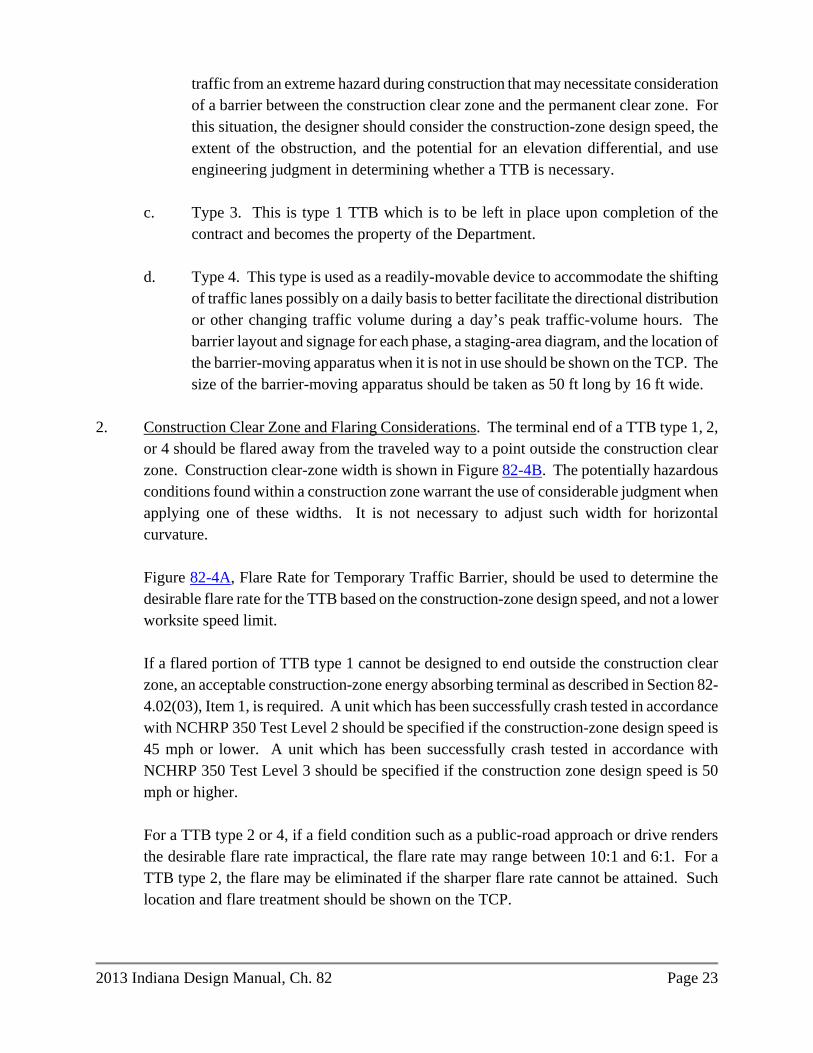
2013 Indiana Design Manual, Ch. 82 Page 23
traffic from an extreme hazard during construction that may necessitate consideration of a barrier between the construction clear zone and the permanent clear zone. For this situation, the designer should consider the construction-zone design speed, the extent of the obstruction, and the potential for an elevation differential, and use engineering judgment in determining whether a TTB is necessary.
c. Type 3. This is type 1 TTB which is to be left in place upon completion of the
contract and becomes the property of the Department.
d. Type 4. This type is used as a readily-movable device to accommodate the shifting of traffic lanes possibly on a daily basis to better facilitate the directional distribution or other changing traffic volume during a day’s peak traffic-volume hours. The barrier layout and signage for each phase, a staging-area diagram, and the location of the barrier-moving apparatus when it is not in use should be shown on the TCP. The size of the barrier-moving apparatus should be taken as 50 ft long by 16 ft wide.
2. Construction Clear Zone and Flaring Considerations. The terminal end of a TTB type 1, 2,
or 4 should be flared away from the traveled way to a point outside the construction clear zone. Construction clear-zone width is shown in Figure 82-4B. The potentially hazardous conditions found within a construction zone warrant the use of considerable judgment when applying one of these widths. It is not necessary to adjust such width for horizontal curvature.
Figure 82-4A, Flare Rate for Temporary Traffic Barrier, should be used to determine the desirable flare rate for the TTB based on the construction-zone design speed, and not a lower worksite speed limit.
If a flared portion of TTB type 1 cannot be designed to end outside the construction clear zone, an acceptable construction-zone energy absorbing terminal as described in Section 82-4.02(03), Item 1, is required. A unit which has been successfully crash tested in accordance with NCHRP 350 Test Level 2 should be specified if the construction-zone design speed is 45 mph or lower. A unit which has been successfully crash tested in accordance with NCHRP 350 Test Level 3 should be specified if the construction zone design speed is 50 mph or higher.
For a TTB type 2 or 4, if a field condition such as a public-road approach or drive renders the desirable flare rate impractical, the flare rate may range between 10:1 and 6:1. For a TTB type 2, the flare may be eliminated if the sharper flare rate cannot be attained. Such location and flare treatment should be shown on the TCP.

Page 24 2013 Indiana Design Manual, Ch. 82
3. Glare Screen. A glare screen may be used in combination with TTB type 1 or type 3 to eliminate headlight glare from opposing traffic. The application is at a crossover transition or in a 2-way, 2-lane operation. Guidance regarding consideration of a glare screen is described in Section 49-4.05(03), though INDOT has not adopted specific warrants for the use of a glare screen.
4. Anchoring. TTB type 1, 2, or 3 should be anchored where indicated on the INDOT Standard
Drawings. The locations of anchored TTB should be shown on the plans. 5. Traffic-Control-Plan Information. Types, locations, and quantities of TTB, including
locations and quantities of glare screens and energy absorbing terminals, along with flare rates should be shown on the TCP for each traffic-maintenance phase.
See Section 17-3.13 for information regarding determination of pay quantities. 82-4.02(03) End Treatment or Impact Attenuator
The following discusses the end treatments or impact attenuators that may be used. 1. Energy-Absorbing Terminal. The use of a construction-zone energy-absorbing terminal
should be based on National Cooperative Highway Research Program Report 350 Test Levels. The Test Level 3 (TL-3) terminal should be specified for an Interstate or other route with a construction-zone speed limit of 50 mph or higher. The TL-2 terminal should be specified for a non-interstate route with a construction-zone speed limit of 45 mph or lower. If a lower temporary worksite speed limit is to occasionally apply, each terminal’s Test Level should still correspond to that for the construction-zone speed limit. The location of each terminal with its Test Level should be shown on the TCP.
2. Guardrail. The treatment for an exposed end of guardrail includes the following:
a. connection to existing barrier; b. using an acceptable end treatment. Use the construction year AADT, and see Section
49-5.04(01); c. flaring the end to a point outside the construction clear zone; or d. burying the end in the backslope.
3. Gravel-Barrel Array. Due to the size of the array, a gravel-barrel array has limited
application in a work zone.

2013 Indiana Design Manual, Ch. 82 Page 25
4. Other. Other INDOT-approved end treatments may be applicable. Chapter 49 provides information on some of the end treatments used by the Department. Provide the most applicable end treatment consistent with cost and geometric considerations.
82-4.03 Design/Layout Where practical, a temporary roadside-safety appurtenance should be designed and located as determined in Chapter 49 (e.g., deflection distance, length of need). However, it is not cost effective to satisfy the permanent-installation criteria due to the limited time a motorist is exposed to a construction hazard. The designer will need to evaluate the exposure time of the hazard in determining the need for installing a roadside-safety appurtenance. The following provides alternatives the designer may consider in designing and locating a temporary roadside-safety appurtenance within a construction zone. 1. Construction Clear Zone. Applying the clear-zone width as described in Chapter 49 to a
work zone is often impractical. Therefore, construction clear-zone width is shown in Figure 82-4B. However, the potentially hazardous conditions found within a construction zone warrant the use of engineering judgment in applying the construction clear-zone distance. It is not necessary to adjust the clear-zone-width value shown in Figure 82-4B for horizontal curvature.
2. Shoulder Widening. Where a temporary barrier is placed adjacent to a shoulder, it is not
necessary to provide extra shoulder widening. 3. Flare Rate. A TCB terminal should be flared beyond the traveled way to a point outside the
construction clear zone. Figure 82-4A provides the desirable flare rate for the TCB based on the selected construction-zone design speed. The designer should provide the flare rate unless extenuating circumstances render it impractical (e.g., stop condition, drive, intersection). See Section 82-4.03.
4. Opening. An opening in the barrier should be avoided. Where an opening is necessary, the
barrier end should be shielded with acceptable end treatment as discussed in Section 83-4.03(03).
82-4.04 Pavement Edge Dropoff on Multilane Divided Highway A pavement edge dropoff should be avoided immediately adjacent to a lane open to traffic during a construction activity such as shoulder rehabilitation or crossover construction.

Page 26 2013 Indiana Design Manual, Ch. 82
In developing a traffic-maintenance plan, the desirable option is to close the lane adjacent to an edge dropoff. This will ensure that the edge dropoff is located outside the construction clear zone. If the traffic lane adjacent to the edge dropoff cannot be closed for an extended period of time, a full-depth rehabilitated shoulder section should be provided that can be placed to within 3 in. of the top of pavement elevation before the end of a day’s work. This should be done, for example, where the shoulder work is to be done at night so that all of the existing traffic lanes can be kept open during daylight hours. The pavement section required to fill a shoulder dropoff to within 3 in. of the top before exposure to adjacent traffic should be obtained from the Office of Pavement Engineering. A unique special provision will be required to address the time frame imposed on the contractor for bringing the shoulder paving up to the required grade. Also, drums should be placed on the shoulder dropoff, spaced as shown in Figure 83-3D, Suggested Maximum Spacing of Channelization Devices. Where it is not feasible to limit exposure to the edge dropoff by the means described above, and the edge dropoff is greater than 3 in., one of the mitigating measures should be considered as follows: 1. Placing a temporary wedge of material along the face of the dropoff. The wedge should
consist of asphalt material placed at a 45-deg angle or flatter. Warning signs should be placed in advance of and throughout the treatment. A 6-in. width solid edge line should be used to delineate the edge of the travel lane.
2. Placing drums along the traffic side of the dropoff and maintaining, if practical, a 3-ft width
buffer between the edge of the travel lane and the dropoff. Warning signs should be placed in advance of and throughout the treatment.
3. Installing a temporary concrete barrier or other acceptable positive protection device with a
buffer between the barrier face and the traveled way. An acceptable crashworthy terminal or flared barrier should be installed at the upstream end of the section. For nighttime use, standard delineation devices must supplement the barrier. Specifying the use of a temporary movable concrete barrier system will involve the use of proprietary materials.
If the work is to include deep milling or asphalt-pavement replacement, and the dropoff between adjacent lanes is greater than 1.5 in., mitigating measure No. 1 or No. 2 should be considered.

2013 Indiana Design Manual, Ch. 82 Page 27
82-5.0 HIGHWAY CAPACITY 82-5.01 Traffic-Capacity Analysis The need for a traffic-capacity analysis during the development of the TCP will be determined on a project-by-project basis. A freeway reconstruction project is a candidate for analysis, as is another project type under similar conditions. Maintaining an acceptable level-of-service during construction is especially important on a freeway or other high-speed rural highway. The operational elements of a facility under construction (e.g., lane segments, ramp, intersection) should maintain a level-of-service which is not less than that provided by the facility prior to construction, although this is not always attainable. Achieving this may require the following: 1. converting a shoulder to a travel lane; 2. eliminating on-street parking (during peak traffic-volume hours or at all times); 3. constructing a temporary lane; 4. opening additional lanes during peak traffic-volume periods; 5. providing public transportation; 6. constructing a jug-handle type configuration for an indirect left-turn at an intersection; 7. closing or metering ramps at an interchange; 8. providing a turnout along long, restrictive stretch of highway construction; 9. constructing a passing blister at a T intersection; 10. providing a two-way, left-turn lane on an urban facility; 11. adjusting signal phasing and timing at an intersection; 12. providing an additional turn lane at an intersection; 13. lengthening a turn-lane storage bay; 14. adjusting acceleration or deceleration length at an interchange ramp; 15. closing an intersection; 16. restricting turns at an intersection; 17. providing extra pavement width; 18. providing signal or flagger control in a 1-lane, two-way operation; 19. public information; or 20. providing a temporary ramp connection. 82-5.02 Queuing Analysis A TCP developed for a freeway reconstruction project should include, at a minimum, a queuing analysis to determine the anticipated traffic backups at particular times of the day. The results of the

Page 28 2013 Indiana Design Manual, Ch. 82
queuing analysis should be included with the proposed TCP and should be used to determine whether or not to consider the following: 1. restricting construction operations to off-peak traffic-volume hours or nighttime; 2. closing a ramp; 3. using alternate routes; 4. developing public relations strategies; or 5. temporary widening for an extra lane or for roadway capacity. If a queuing analysis is required, the designer should use the FHWA computer program QUEWZ or other approved program to accomplish the task. QUEWZ is designed to evaluate a freeway work zone, but the designer may find it useful for another type of highway with 4 or more lanes. Section 81-4.0 provides additional information on the program. The program can provide the following: 1. estimation of vehicular capacity through a work zone; 2. calculation of average speed; 3. calculation of delay through a lane-closure section; 4. calculation of queue length; 5. estimate of percentage of diverted traffic; and 6. total user cost. 82-6.0 APPLICATIONS Section 81-2.0 discusses the factors to consider in determining which construction application to use. The following provides the design considerations for such applications. 82-6.01 Lane or Shoulder Closure In addition to the INDOT Standard Drawings, the designer should consider the following for a lane or shoulder closure. 1. Taper. A lane closure, lane-width reduction, or lane shift requires the use of a transition
taper to safely shift traffic around the encroaching restriction. The designer should review Sections 82-3.03 and 83-3.02 regarding a transition taper.
2. Sight Distance. Provide decision sight distance to the beginning of the lane closure or
transition. Section 82-3.04 provides additional information on sight distance within a construction zone.

2013 Indiana Design Manual, Ch. 82 Page 29
3. Lane Width. Section 82-3.02 provides the Department’s criteria for reduced lane width. 4. Shoulder Usage as Travel Lane. If the TMP involves placement of traffic on the shoulder or
a portion of the shoulder, the designer should make a written request to the Office of Pavement Engineering, regarding the shoulder’s use. The construction year AADT, percent trucks of AADT, and the approximate length of time during which traffic is expected to use the shoulder should be provided.
The median shoulder should be replaced with a 6-ft width section. See the INDOT Standard
Drawings. The proposed median shoulder for the new pavement section constructed in the first phase should also be 6 ft wide. Its pavement design should be provided by the Office of Pavement Engineering. Such shoulder will carry traffic during subsequent phases. The entire 6-ft width should remain in place. Shoulder corrugations are to be milled into the new shoulder after traffic is crossed over to the other roadway.
5. Lane Closure. The length of a lane closure should be held to a minimum so that the motorist
is not passing a long section of a closed lane where no work activity is occurring. 6. Roadside Safety. A roadside barrier should not be used as a transition device. A transition
should be provided with the appropriate traffic-control devices (see Chapter 83). Provide sufficient distance between the transition devices and roadside barrier to allow an errant motorist to safely return to the traveled way. A roadside barrier (e.g., temporary traffic barrier) may be used as a channelization device beyond the taper. When shifting traffic to be next to a roadside barrier, the shy distance, as discussed in Section 49-5.0, should be provided.
7. Traffic-Control Devices. Chapter 83 and the INDOT Standard Drawings provide the
Department’s criteria for the placement of traffic-control devices. 8. Bridge. Figure 82-6A, Lane Closure on a Bridge, illustrates a TCP for closing a lane on a
bridge-reconstruction or -rehabilitation project. Figure 82-6A is applicable to a 30-ft wide structure on a 4-lane divided facility. The designer will need to adjust the design for another situation. Figure 82-6A provides the detail for a left-lane closure. This detail may also be used for a right-lane closure.
9. Roadway Under Overpass Structure. Work may include full-depth bridge-deck patching,
structure removal or placement not protected by a bridge railing, or other work activity that affects under passing lanes that are open to traffic. Such work may not take place directly above such lanes. Appropriate warning signs and traffic-control devices should be provided

Page 30 2013 Indiana Design Manual, Ch. 82
on the under passing roadway to warn motorists of lane closures for such work. Such signs and devices are required if no work is being done on the under passing roadway.
82-6.02 Two-Way Traffic on a Divided Highway The following provides the considerations for where two-way traffic is to be placed onto a single roadway of a divided highway. 1. Length. The optimum segment length is less than 4 mi. Where the segment length exceeds 4
to 5 mi, operational efficiency may be severely reduced as traffic backs up behind slower vehicles.
2. Positive Protection.
a. Freeway. Temporary traffic barrier along with temporary solid yellow lines as shown on the INDOT Standard Drawings should be used within each crossover and between the crossovers to separate opposing traffic.
b. Other Multilane Roadway. Tubular markers should be used to enhance the
delineation and separation of the opposing traffic flows on each side of a temporary double solid yellow line. The tubular markers are placed onto the pavement between the solid yellow lines as shown on the INDOT Standard Drawings.
Where construction activities require temporary revision of traffic patterns within the construction zone to two-lane two-way operation at or near an intersection, the end of the temporary double solid yellow line should match the end of the existing broken white lane line.
For a roadway with lanes which are narrower than 12 ft without paved or aggregate shoulders, compacted aggregate size No. 73 is required where slope and ditch conditions permit, as shown on the INDOT Standard Drawings. Such conditions must be assessed when developing the traffic-control plan. The cross slope of each temporary compacted aggregate shoulder is to be as shown on the INDOT Standard
Drawings. Quantities for the compacted aggregate must be determined. 3. Roadside Safety. Where traffic is directed onto the opposing roadway, the designer should
consider the effect this will have on the operational characteristics of roadside appurtenances. For example, an existing trailing end of an unprotected bridge railing may require an

2013 Indiana Design Manual, Ch. 82 Page 31
approach-guardrail transition or impact attenuator. A blunt guardrail terminal may need to be protected with an acceptable end treatment.
4. Crossover. The following should be considered in the design of a crossover.
a. The taper for a lane drop should not be contiguous with the crossover. See Section 82-3.03 for the acceptable taper rate and length.
b. The crossover should have a construction-zone design speed that is not more than 10
mph below the posted speed limit before the construction zone; see Section 82-3.01.
c. The crossover design should accommodate the anticipated truck traffic of the roadway (e.g., surfacing width, loads).
d. A clear recovery area should be provided adjacent to the crossover; see Section 82-
4.04.
e. Temporary traffic barrier and the excessive use of traffic-control devices cannot compensate for a poor geometric design of a crossover.
f. Provide signing prior to the crossover to indicate the length of the 2-way, 2-lane
section. In addition, signing may be provided within the 2-lane section indicating the remaining distance of the 2-lane section.
5. Interchange. Maintain access to a freeway interchange ramp if the work space is in the lane
adjacent to the ramps. An additional crossover for the purpose of maintaining full interchange access may be required. If interchange access is not feasible or presents a capacity problem, a ramp should be closed using proper detour signing for alternative routes. Where a ramp closure is deemed necessary, early coordination should be conducted with local officials having jurisdiction over the affected crossroad or street. The designer should also check that sufficient deceleration or acceleration distance is maintained where there is work in the vicinity of an interchange ramp. If this is not practical, additional traffic control devices or closing the ramp may be required. The designer should review the safety aspects and conduct a capacity analysis to determine the appropriate action.
7. Capacity. Conduct a capacity analysis to ensure that traffic can be reasonably handled in the
one lane. If not, an alternate construction application should be considered (e.g., lane shift to the shoulder).

Page 32 2013 Indiana Design Manual, Ch. 82
The needs of a left-turning motorist should be considered in developing a phased-construction scheme that reduces a 4-lane road to one lane in each direction.
82-6.03 Interstate Highways Congestion Policy [Rev. Feb. 2012] It is Department policy to prohibit operations which restrict lanes or otherwise cause congestion to occur on an Interstate Route. Such operations may not be conducted except as described in the Interstate Highways Congestion Policy (IHCP). Policy exceptions and waivers are processed through the Office of Traffic Support, Work Zone Safety Section. Waivers to a prior Interstate Lane Closure Policy remain valid. The IHCP is available for download at http://www.in.gov/indot/2731.htm. 82-6.04 Runaround or Detour In addition to the criteria shown on the INDOT Standard Drawings, a temporary runaround or specially-built detour should satisfy the geometric and roadside-safety criteria provided in Sections 82-3.0 and 82-4.0. The embankment for a temporary runaround should be shown on the mainline cross sections. If the AADT is 5,000 or greater, or if the percent trucks is 10% or greater, a project-specific pavement design is required for a temporary runaround. See the INDOT Standard Drawings for the pavement section to be used if the AADT is less than 5000, or if the percentage of trucks is less than 10%.
** PRACTICE POINTER **
Unofficial detour routes should not be shown
on the plans or described in the special provisions.

2013 Indiana Design Manual, Ch. 82 Page 33
A temporary runaround should be in accordance with the design criteria included herein. The following Level One elements should satisfy the criteria as follows.
Element Design Criterion
1. Design speed Section 82-3.01 2. Lane width Section 82-3.02 3. Shoulder width Section 82-3.02 4. Bridge width Standard Specifications Section 713.04 5. Structural capacity Standard Specifications Section 713.04 6. Horizontal curvature Figure 82-3A 7. Superelevation transition length Section 82-3.05 and Chapter 43 8a. Stopping sight distance Section 82-3.04. Design speed
at horizontal curve should be used in the construction zone. Section 43-4.0
8b. Stopping sight distance at Sag: Section 82-3.06; vertical curve Crest: Section 82-3.04 and Chapter 44. 9. Maximum grade 3R criteria for the design speed for the construction zone, appropriate functional classification, and rural or urban environment.
10. Through lane cross slope 3R criteria for the appropriate functional classification
and rural or urban environment. If the existing shoulder is used for through traffic, 4% cross slope will be acceptable.
11. Superelevation rate Section 82-3.05 12. Vertical clearance 3R criteria for the appropriate functional classification. 13. Americans with Disabilities Act Section 51-1.08, where sidewalk
requirements exists prior to construction. 14. Bridge-railing safety performance Standard Specifications
Section 713.04 If the design for a temporary runaround or other traffic-maintenance means does not satisfy the above criteria, a design exception must be requested. The procedure established in Section 40-8.0 should be followed.

Page 34 2013 Indiana Design Manual, Ch. 82
The INDOT reviewer should verify that the above criteria are satisfied as part of the limited review of a consultant-designed project. A TCP checklist is shown as Figure 82-7A. An editable version of this form may also be found on the Department’s website at www.in.gov/dot/div/contracts/design/dmforms/.

Participant
Project Stage Scoping
of Project
Prelim. Field Check
Hearing Final Field Check
Final Plan
Review Designer X X X X X Office of Environmental Services X X X X X Consultant (if applicable) X X X X District X X X X Federal Highway Administration (if applicable)
X X X
Communications Division (if applicable) X X X Local Public Agency (City or Town, County, School, Fire Department)
X X X X
Highway Operations Division (TMP) X X X
PARTICIPANTS DURING TRAFFIC-CONTROL-PLAN DEVELOPMENT
Figure 82-2A
2013

TRAFFIC-MAINTENANCE QUESTIONNAIRE English-Units Project
, 20
MEMORANDUM TO:
District Deputy Director ATTENTION:
District Traffic Office Manager ATTENTION:
District Design Office Manager FROM:
Project Manager SUBJECT: Traffic Maintenance for English-Units Project
Route: Des.: Project No.: Bridge File: Location: County:
Description: We are preparing plans for the project identified above and are in the process of evaluating the relative merits of a temporary bridge and runaround, maintaining traffic through the project limits, or a detour during the construction period. In order that district input may be considered in this decision, we ask that you complete the blanks in this memorandum and return it to:
Project Manager Indiana Department of Transportation 100 North Senate Ave., Room N642 Indianapolis, IN 46204-2216
If a detour is recommended, please submit the official detour map and signage with this memorandum with the blanks filled in. If the official detour route is totally over local roads, please initiate early coordination with the affected local public agency or agencies regarding the unofficial detour route. The Engineer’s Report recommended the following:
a temporary runaround should be used;
2013

traffic should be maintained through the project limits; an official detour should be used.
The AADT during the construction year is
A. TRAFFIC-MAINTENANCE OPTIONS ANALYSIS
1. OPTION 1: TEMPORARY RUNAROUND
RUNAROUND COMPUTATIONS FURNISHED BY DESIGNER Length of Runaround, ft* x Cost per Foot** ft x $ = $ Length of Temporary Bridge x $1,000/ft or Cost of Pipe
ft x $1,000 = $
$ Total Runaround Cost (Total Cost Option 1) $
* Length of Runaround = Distance from tie-in point to tie-in point minus Length of
Temporary Bridge.
** For average fill height ≤ 6 ft, use $120/ft For average fill height > 6 ft, increase as necessary
2. OPTION 2: TRAFFIC MAINTAINED THROUGH PROJECT LIMITS
Length of Roadway Treatment, ft* x Cost per Foot* ft x $ = $ Length of Temporary Concrete Barrier x Cost per Foot ft x $ = $ Cost of Crossovers $ Total Maintained-Traffic Cost (Total Cost Option 2)
$
3. OPTION 3: INDOT-ROUTES OFFICIAL DETOUR a. Best available official detour route over INDOT routes:
b. Extra distance to be traveled by through traffic using this route: mi
c. Percent of the traffic which would use this detour route: % d. Road(s) that would be used as an unofficial detour route:
2013

(1) Existing condition and type of pavement for each road, (i.e., good, very good,
rutted, gravel, asphalt, etc.)
(2) Distance over the above unofficial detour route: mi
INDOT-ROUTES OFFICIAL-DETOUR COMPUTATIONS
Detour Through Local Detour Duration (days) Extra Distance (mi) Vehicles per Day User Cost per Mile $0.30 $0.30 Total User Cost $ $
User Cost = Detour Duration x Extra Distance x Vehicles per Day x $0.30/mi
e. Total User Cost = Through User Cost + Local User Cost. Therefore, Total User Cost
= $ . f. Estimated payment to local public agencies due to use of unofficial detour route
= $ .
Total Cost Option 3 (e + f) $
4. OPTION 4: LOCAL-ROADS OFFICIAL DETOUR
a. Best available official detour route over local roads. It is feasible for this route to include one or more INDOT routes.
b. Extra distance to be traveled by through traffic using this route: mi
c. Percent of the traffic which would use this detour route: % d. Cost to upgrade the local roads to accommodate INDOT traffic:
$ e. Existing condition and type of pavement for each road. (i.e., good, very good, rutted,
gravel, asphalt, etc.)
LOCAL-ROADS OFFICIAL DETOUR COMPUTATIONS
Detour Through Local Detour Duration (days)
2013

Extra Distance (mi) Vehicles per Day User Cost per Mile $0.30 $0.30 User Cost $ $ Cost to Improve Local Roads (See Item 3b)
$ n/a
User cost = Detour Duration x Extra Distance x Vehicles per Day x $0.30/mi
Total User cost = Through User Cost + Local User Cost + Cost to Improve Local Roads. Therefore, Total Cost Option 4 = $
B. AFFECTS OF PROJECT WORK ON PUBLIC SERVICES
1. TIME DELAYS Fire and police protection: min Emergency medical service: min Postal service: min
2. SCHOOL BUSES
Number of school buses using the facility per day: Additional travel distance required per bus: mi Total additional school-bus travel distance required mi
3. BUSINESSES AND PUBLIC FACILITIES
Businesses or public facilities which are sensitive to the presence of this road work, and the degree of impact the work would have:
C. DISTRICT RECOMMENDATION
1. RECOMMENDATION: Rationale for this recommendation if it is different than what is included in the Engineer’s Report:
2. DETOUR ROUTE MARKER ASSEMBLIES:
If an official detour is recommended, detour route marker assemblies will be required.
3. MAP OF OFFICIAL DETOUR:
If an official detour is recommended, a map of the detour with sign locations is shown on an accompanying sheet.
2013

Construction Zone Design
Speed, V (mph)
fmax for Open-Roadway
Conditions
Normal Crown Section Minimum Radius, Rmin (ft),
e = -0.02
Superelevated Section Minimum Radius, Rmin (ft),
e= +0.08 20 0.17 180 110 25 0.17 280 170 30 0.16 430 250 35 0.15 630 360 40 0.15 820 470 45 0.14 1130 620 50 0.14 1390 760 55 0.13 1840 960
Notes: 1. Curve Radius. The radius is calculated from the equation as follows:
; )f + (e 1
V = R2
maxmin 5
Value shown in the table for design has been rounded up to the next higher 10-ft increment.
2. Normal-Crown Section. If the normal-crown section is maintained through the horizontal
curve, the superelevation rate is -0.02 assuming a typical cross slope of 2%. Therefore, the Rmin column with e = -0.02 lists the minimum radius which can be used if retaining the normal section through the horizontal curve.
3. Other Radius. For a proposed radius or superelevation rate intermediate between the table
values, the equation in Note 1 may be used to determine the proper curvature layout. For example, if the construction-zone design speed is 55 mph and the proposed curve radius is 1000 ft, the superelevation rate is determined as follows:
f - R 1
V = e2
5
.12 - ))((1
)( = e2
010005
55
07.0+ = e
MINIMUM RADIUS FOR HORIZONTAL CURVE
IN CONSTRUCTION ZONE
Figure 82-3A
2013

Construction-Zone
Design Speed (mph)
Calculated K Value
(K = V2/46.5)
K Value Rounded For
Design 20 8.6 9 25 13.4 14 30 19.4 20 35 26.3 27 40 34.4 35 45 43.5 44 50 53.8 54 55 65.1 66
KA = AV = L2
5.46
Where:
L = Length of vertical curve, ft A = Algebraic difference between grades, % K = Horizontal distance required to effect a 1% change in gradient V = Design speed, mph
K VALUE FOR SAG VERTICAL CURVE (Comfort Criteria in a Construction Zone)
Figure 82-3B
2013
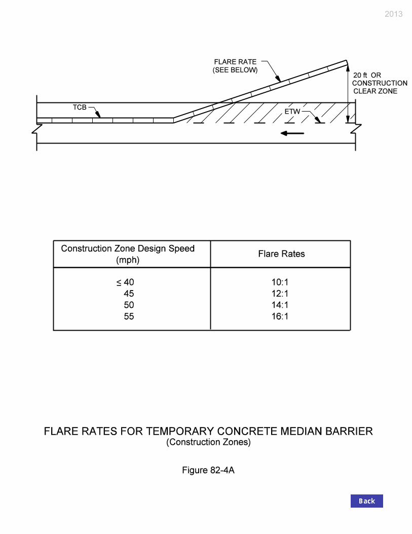
2013

Construction-Zone Design Speed
Cut Slope Fill Slope
3:1 4:1 5:1 6:1 Flatter
Than 6:1 6:1 5:1 4:1 3:1
40 mph or lower 8 8 8 8 8 8 8 8 10 See Note
2
45 mph 8 8 8 8 8 8 10 10 12 50 mph 8 10 10 10 10 10 12 13 15 55 mph 8 12 12 12 12 12 13 15 18
Notes:
1. Width is measured from the edge of traveled way.
2. For a facility with 3:1 fill slopes, the clear-zone width shown above should be used in conjunction with the procedures described in Section 49-2.03(01).
CLEAR-ZONE WIDTH (ft) FOR CONSTRUCTION ZONE
Figure 82-4B
2013
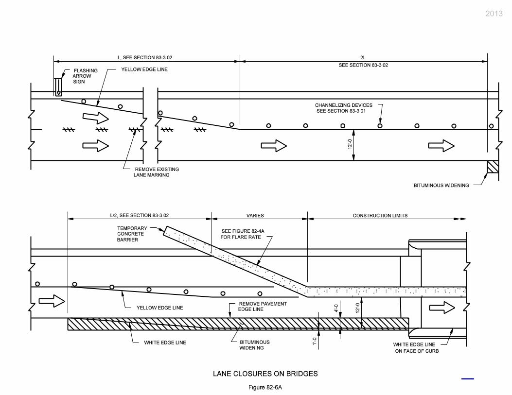
2013

This figure deleted. For related information, see the Interstate Highways Congestion Policy (IHCP), available for download at http://www.in.gov/indot/2731.htm.
INTERSTATE LANE CLOSURE POLICY – STATEWIDE Figure 82-6B
2013

This figure deleted. For related information, see the Interstate Highways Congestion Policy (IHCP), available for download at http://www.in.gov/indot/2731.htm.
INTERSTATE LANE CLOSURE POLICY – SELECTED URBAN AREAS Figure 82-6C
2013

TRAFFIC-CONTROL-PLAN CHECKLIST Route Des GENERAL INFORMATION
YES NO n/a On Plans
1. Has a transportation management plan been developed?
a. Have all recommendations been implemented? b. Has Environmental Policy Team been notified of
major changes?
2. Have all applicable work-zone types listed below been adequately considered?
a. Work outside of roadway b. Lane constriction c. Lane closure d. One-lane, two-way operation e. Runaround f. Intermittent closure g. Use of shoulder or median as travelway h. Crossovers i. Two-way traffic on one roadway of divided facility j. Detour
3. Has all information listed below been incorporated into the contract plans?
a. INDOT Standard Drawings b. INDOT Standard Specifications c. Recurring special provisions d. Unique special provisions e. Detail plans
4. Will extra publicity be required prior to letting (e.g., radio, T.V., newspaper, clubs)?
5. The contractor can restrict the roadway during:
a. Morning or evening rush hour i. One direction ii. Both directions
b. Local celebration c. Holidays or weekends d. Other special event: e. Overnight
6. Nighttime hours of operation required? If Yes, When? a. Between p.m. and a.m.
b. Are special precautions needed (e.g., lighting, clearance lights on equipment)?
2013

GENERAL INFORMATION (Cont’d.) YES NO n/a On Plans 7. Are there changes that cannot be made concurrently for
traffic routing, fire, police, etc.? If Yes, What?
8. Can two adjacent street or road crossings be closed at the same time? If Yes, where or which ones?
9. Will the source of material from off the project site interfere with traffic?
a. On and off project limits b. Certain roads may not be used (e.g., environmental,
recreational). If Yes, which ones?
10. Is the contractor required to provide advance notice for a change in traffic pattern?
11. The starting or completion date is controlled by:
a. School closings or openings b. Holiday: c. Other projects d. Sporting event: e. Other:
12. Are there present or future contracts in the immediate area that may affect traffic or the Contractor’s operations?
DETOUR YES NO n/a On Plans 1. Will traffic be detoured? If Yes, is the detour adequate
in terms of:
a. Weight restriction b. Height – width c. Wide load d. Capacity e. Adequate traffic-control devices f. Railroad crossing and controls g. Geometrics (turning radius, etc.) h. Restriction on bridge or other structure
If No for a. through h., what correctives can be taken?
2. Will trucks using the detour conflict with other traffic using the detour?
2013

DETOUR (Cont’d.) YES NO n/a On Plans 3. Will there be other construction along the detour that
can influence traffic flow?
4. Have other affected Districts or States been notified? 5. If the detour is to be established on ot her than a State
highway, has contact been made with:
a. County? b. City? c. Town?
6. Will there be an unofficial detour? If Yes, has a Letter of Understanding been sent to the local officials?
7. Will all fronting businesses have acceptable ingress and egress?
8. Can the detour be continued over winter (snow removal)?
9. Are alternate routes available to local motorists? 10. Should the following be contacted?
a. Public-school system b. Public-transit system c. Police, fire, or ambulance services d. Postal mail-route service e. Others:
If any Yes, list who and when, with telephone numbers.
11. Has the District established a detour route? WORK ZONE YES NO n/a On Plans 1. Will capacity be restricted? If Yes, what is extent of
restriction?
a. Where will excess traffic be diverted?
b. Can an alternate route handle the traffic?
2013

WORK ZONE (Cont’d.) YES NO n/a On Plans 2. How will staging be addressed (e.g., lengths of times of
permitted construction)?
a. As shown on plans b. Have the contractor provide a plan c. The contractor may stage work differently than
shown on plans
3. Where runaround or temporary widening is required:
a. What criteria should be applied regarding: i. Design speed? mph ii. Lane widths? ft iii. Alignment? iv. Pavement thickness? in. v. Pedestrian traffic?
b. Has the location been determined? 4. Number of lanes maintained in each direction:
a. At all times, One Two b. During rush hours, One Two Three c. Reversible lanes required, One Two
5. What is the facility’s traffic-carrying capability considering the effect of winter:
a. Adequate b. Special traffic-control devices are required c. Procedure modifications are necessary for snow removal and maintenance
d. Modifications are required to the pavement structure:
i. HMA Base ii. HMA Base and Surface
TRAFFIC-CONTROL DEVICES YES NO n/a On Plans 1. Traffic-control signing layout will be:
a. Shown on the plans b. Available prior to contract letting c. Consisting of special traffic delay or advance signs d. That for temporary crossover, designed to match
INDOT Standard Drawings
2. Will the effects of construction operation require sign message modifications to permanent signage?
2013
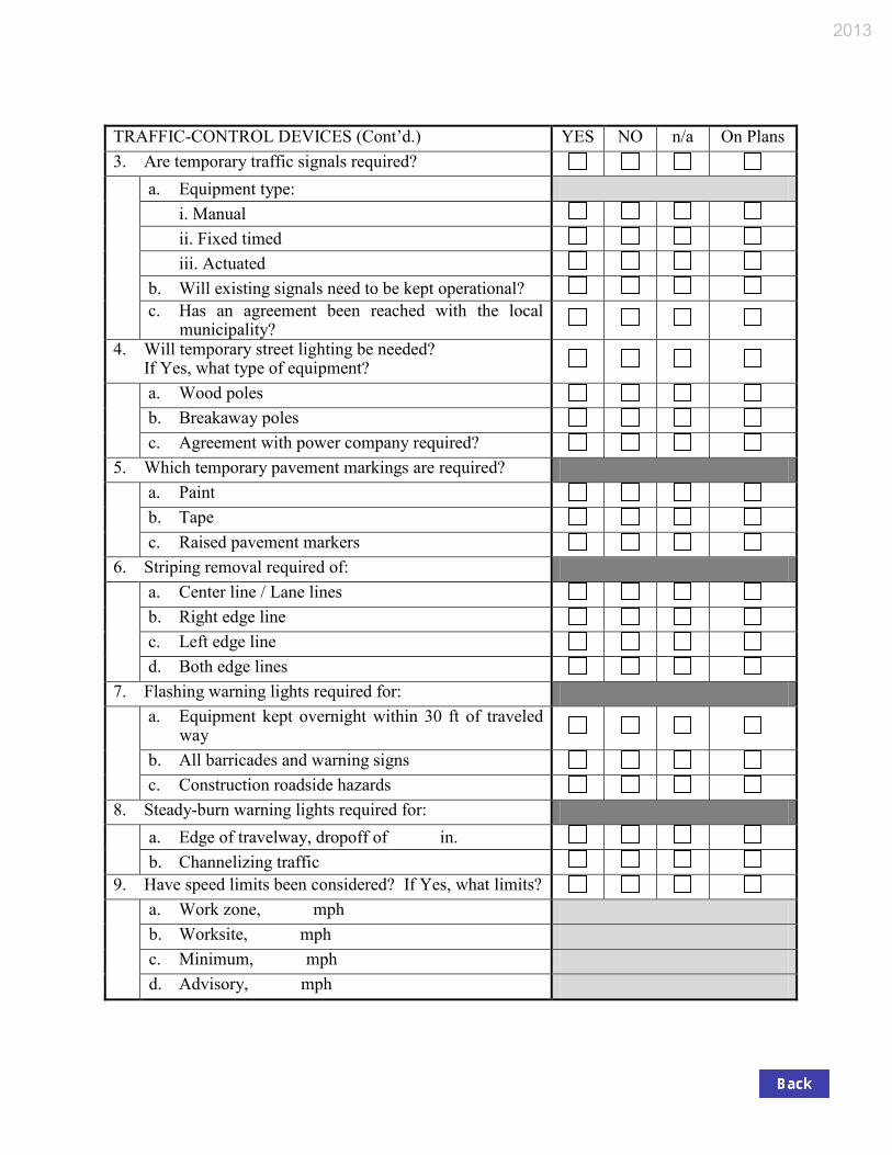
TRAFFIC-CONTROL DEVICES (Cont’d.) YES NO n/a On Plans 3. Are temporary traffic signals required?
a. Equipment type: i. Manual ii. Fixed timed iii. Actuated b. Will existing signals need to be kept operational? c. Has an agreement been reached with the local
municipality?
4. Will temporary street lighting be needed? If Yes, what type of equipment?
a. Wood poles b. Breakaway poles c. Agreement with power company required?
5. Which temporary pavement markings are required?
a. Paint b. Tape c. Raised pavement markers
6. Striping removal required of:
a. Center line / Lane lines b. Right edge line c. Left edge line d. Both edge lines
7. Flashing warning lights required for:
a. Equipment kept overnight within 30 ft of traveled way
b. All barricades and warning signs c. Construction roadside hazards
8. Steady-burn warning lights required for:
a. Edge of travelway, dropoff of in. b. Channelizing traffic
9. Have speed limits been considered? If Yes, what limits?
a. Work zone, mph b. Worksite, mph c. Minimum, mph d. Advisory, mph
2013

ROADSIDE SAFETY YES NO n/a On Plans 1. Temporary barriers
a. Required for traffic protection b. Required for workers’ protection c. Delineation of barriers provided by: i. Electrical devices ii. Reflectorization d. Upon completion of project, retained by: i. Department ii. Contractor
2. Will temporary impact attenuators be required? If Yes, Type
3. Extra protection will be required for:
a. Pedestrians b. School area and crossings c. Playground or park d. Type of protection:
4. Where may the contractor store equipment, construction material, or waste material?
a. On site with flashers or other protection b. 30 ft or more from edge of traveled way c. Designated storage site
5. Where may contractor’s employees park personal vehicles?
a. On-site b. Off-site
2013

INDIANA DEPARTMENT OF TRANSPORTATION—2013 DESIGN MANUAL
CHAPTER 83
Traffic Control Devices in a Construction Zone
Design Memorandum
Revision Date
Sections Affected
16-06 Mar. 2016 Section 83-5.0, Figure 83-5A
NOTE: This chapter is currently being re-written and its content will be included in Chapter 503 in the future.

Page 2 2013 Indiana Design Manual, Ch. 83
TABLE OF CONTENTS
TABLE OF CONTENTS ................................................................................................................ 2
LIST OF FIGURES ......................................................................................................................... 3
83-1.0 GENERAL .......................................................................................................................... 4 83-1.01 References .................................................................................................................... 4 83-1.02 MUTCD Context .......................................................................................................... 4 83-1.03 Official Action .............................................................................................................. 5
83-2.0 HIGHWAY SIGNS ............................................................................................................ 5 83-2.01 Sign-Legend Measurement Units ................................................................................. 5 83-2.02 Placement ..................................................................................................................... 6 83-2.03 Regulatory Signing ....................................................................................................... 6
83-2.03(01) Work-Zone and Work-Site Speed Limit Signing [Rev. June 2012] .................. 6 83-2.03(02) “Stop” or “Yield” Sign ....................................................................................... 8 83-2.03(03) Selective-Exclusion Sign ................................................................................... 8
83-2.04 Advance-Warning Sign ................................................................................................ 9 83-2.05 Guide Sign .................................................................................................................. 10 83-2.06 Portable Changeable Message Sign [Rev. May 2012] ............................................... 12
83-2.06(01) Need [Rev. May 2012] ..................................................................................... 12 83-2.06(02) Design Considerations [Rev. May 2012] ......................................................... 13 83-2.06(03) Plans Requirements [Added May 2012] .......................................................... 13 83-2.06(04) TMC Control of PCMS Operation [Added May 2012] ................................... 14
83-2.07 Flashing-Arrow Sign .................................................................................................. 15
83-3.0 CHANNELIZATION DEVICES ..................................................................................... 16 83-3.01 Types .......................................................................................................................... 16 83-3.02 Taper Length ............................................................................................................... 19 83-3.03 Spacing ....................................................................................................................... 19 83-3.04 Type III Barricade ....................................................................................................... 19
83-4.0 PAVEMENT MARKINGS .............................................................................................. 20 83-4.01 Types .......................................................................................................................... 20
83-4.01(01) Paint ................................................................................................................. 20 83-4.01(02) Temporary Raised Pavement Markers ............................................................. 21 83-4.01(03) Temporary Pavement-Marking Tape ............................................................... 21 83-4.01(04) Thermoplastic or Epoxy Markings ................................................................... 21 83-4.01(05) Buzz Strips ....................................................................................................... 22
83-4.02 Application ................................................................................................................. 22
83-5.0 TEMPORARY TRAFFIC SIGNAL [Rev. Mar. 2016] ..................................................... 22

2013 Indiana Design Manual, Ch. 83 Page 3
83-5.01 Location ....................................................................................................................... 22 83-5.02 Application [Rev. Mar. 2016] ..................................................................................... 23
83-6.0 HIGHWAY LIGHTING ................................................................................................... 26 83-6.01 Types .......................................................................................................................... 26 83-6.02 Warrants ..................................................................................................................... 26
FIGURES ...................................................................................................................................... 28 LIST OF FIGURES Figure Title 83-2A English to Metric Conversions 83-2B Suggested Freeway Speed Limits (Work Zones and Work Sites) 83-2C Advance Warning Signs 83-2D Suggested Use and Location of Flashing Arrow Signs 83-2E Programming Information for Portable Changeable Message Sign 83-3B Taper Length Criteria for Construction Zones 83-3C Taper Length Criteria for Construction Zones (Application) 83-3D Suggested Maximum Spacing of Channelization Devices 83-4A Buzz Strips 83-5A Vehicle Detection Typical Placement Areas [Added Mar. 2016]

Page 4 2013 Indiana Design Manual, Ch. 83
CHAPTER 83
TRAFFIC CONTROL DEVICES IN A CONSTRUCTION ZONE
83-1.0 GENERAL The proper use of traffic control devices is critical to both public and worker safety and has been proven to significantly reduce accidents in a construction zone. This Chapter provides supplemental information on these devices and provides specific Department policies and procedures. For additional information, the designer is encouraged to review the references listed in Section 83-1.01. 83-1.01 References For additional information on the design, application, and placement of traffic control devices in a work area, the designer is referred to the latest editions of the publications as follows: 1. Manual on Uniform Traffic Control Devices (MUTCD), FHWA; 2. INDOT Standard Drawings; 3. INDOT Standard Specifications; 4. Indiana Design Manual, Section 502-1.0 – Roadway Signing; 5. Indiana Design Manual, Section 502-2.0 – Pavement Markings; 6. Indiana Design Manual, Section 502-3.0 – Traffic Signals; 7. Indiana Design Manual, Section 502-4.0 – Highway Lighting. The INDOT publications can be obtained by contacting the Contract Administration Division. For other publications, the indicated source should be contacted. 83-1.02 MUTCD Context Throughout the MUTCD, the words shall, should, and may are used to describe the appropriate application each traffic-control device. The MUTCD defines the terms as follows: 1. Shall. A mandatory condition. Where certain requirements in the design or application of a
device are described with the “shall” stipulation, it is mandatory that if an installation is made that these requirements be met.

2013 Indiana Design Manual, Ch. 83 Page 5
2. Should. An advisory condition. Where the word should is used, it is considered to be
advisable usage, recommended but not mandatory. 3. May. A permissive condition. No requirement for design or application is intended. 83-1.03 Official Action An Official Action is required before installing a regulatory temporary traffic control device, if a proposed change is made to a facility’s regulatory control. For example, an Official Action is required where a proposed change is made regarding a parking restriction, intersection control, no-passing zone, traffic signal, or work-zone speed limit. However, Indiana Statutes provide for the establishment of an enforceable reduced speed limit in a work site without an Official Action (see Section 83-2.03). For a State-controlled facility, the designer must contact the appropriate INDOT district Traffic Engineer and obtain a copy of the approved Official Action, and include it in the contract documents. For a locally-controlled facility, approval (i.e., local ordinance) must be obtained from the appropriate jurisdiction. 83-2.0 HIGHWAY SIGNS In a construction zone, a regulatory sign is used to temporarily override an existing mandate or prohibition (e.g., reduced speed limit). A warning sign is used in advance of the construction area to indicate a potentially-hazardous condition. A guide sign is used to inform the motorist of a detour route, destination, or point of interest. The INDOT Standard Drawings, the INDOT Standard Specifications, and MUTCD Part VI provide the Department’s criteria for the design, application, and placement of signs in a construction zone. This Section provides the designer with supplemental information on the application of a highway sign. The designer should review Section 502-1.0 and the MUTCD regarding permanent signs. 83-2.01 Sign-Legend Measurement Units Regulatory or advisory speed limit, distance message, or other sign legend displayed in a construction zone will remain in English units until notified otherwise. Figure 83-2A provides guidelines for converting English units to metric.

Page 6 2013 Indiana Design Manual, Ch. 83
83-2.02 Placement The uniform placement of construction signing, although desirable, is not always practical. Road geometrics or other factors often dictate a more advantageous placement. The designer should consider the following guidelines together with established criteria in determining the placement of construction signing. 1. Permanent Sign. A construction sign in close proximity to a permanent sign should be
reviewed after the theoretical temporary sign location has been determined. For example, the permanent sign should not block the view of the temporary sign nor convey conflicting information. The designer should also avoid creating an information overload by placing too many signs near each other.
2. Intersection. If construction signing is warranted near an intersection, the designer should
consider placing the temporary sign beyond the intersection. On the intersection approach, a permanent sign provides control and directional information to the motorist. Locating a construction sign beyond the intersection will usually enhance a motorist’s comprehension of the sign.
3. Roadside Barrier. The designer should consider placing a temporary construction sign
behind an existing roadside barrier if practical. This will reduce the probability that it will be impacted.
83-2.03 Regulatory Signing 83-2.03(01) Work-Zone and Work-Site Speed Limit Signing [Rev. June 2012] Different speed limits may apply based on whether the speed limit is within the work zone or if it is within a work site. The work-zone speed limit applies throughout the project as does a work-site speed limit authorized for continuous use to protect motorists. A work-site speed limit authorized for intermittent use to protect workers applies to a specific location within the work zone where work is actually occurring. The following provides guidance in the selection and implementation of a work-zone or work-site speed limit. 1. Work-Zone Speed Limit. The work-zone speed limit will be determined based on the
construction-zone design speed, traffic volume, work type, geometrics, project length, etc. The work-zone speed limit should not exceed the construction-zone design speed through the construction area. Section 82-3.01 provides guidance on the selection of a construction-zone design speed. If the work-zone speed limit is different than the existing posted speed limit

2013 Indiana Design Manual, Ch. 83 Page 7
prior to the start of construction, an Official Action as discussed in Section 83-1.03 will be required.
2. Work-Site Speed Limit. Indiana Statutes permit INDOT to establish a work-site speed limit
without an Official Action. They also stipulate that the work-site speed limit will be at least 10 mph below the original posted speed limit. An intermittent work-site speed limit will be applicable only where and while work is actually in progress and workers are present, and is authorized by the district Traffic Engineer. The district Technical Services Director will authorize a work-site speed limit for continuous use. Additional signs for the normal speed limit should be specified to aid enforcement by properly defining the speed zones as follows:
a. For a rural Interstate-route application, R2-1-B and R2-Y2-B signs for the normal
speed limits should be placed approximately 500 ft downstream from the end of the work site.
b. For another application, an R2-1 or R2-1-B sign for the normal speed limit should be
placed 500 ft downstream from the end of the work site. The additional signs for the normal speed limit may be omitted if such existing signs are
located within sight distance. As an option, the R2-Y12 or R2-Y12-B “End Work Site Speed Limit” sign may also be provided alongside the sign for the normal speed limit at the end of the work site. The statutes also stipulate that the work-site speed limit will either be 45 mph, or 10 mph below the original posted speed limit, whichever is lower.
3. Sign Size and Assembly. A work-zone or work-site speed-limit-sign assembly should be
placed according to the MUTCD and should be of a size specified for the facility. Each work-site assembly should include a “Worksite” plaque mounted above the regulatory sign.
4. Flashing Beacon. Each work-site speed-limit-sign assembly for intermittent use must
incorporate strobe-type flashing beacons with one mounted at each upper corner of the regulatory sign. A “When Flashing” plaque must be placed below the sign. The beacons should be activated only while work is in progress and workers are present. The device provides for both workers’ and public safety without imposing unnecessary travel delays during non-working periods. Flashing beacons and the “When Flashing” plaque will not be incorporated with a continuous-use work-site speed limit.
5. Selection. Figure 83-2B provides suggested work-zone and work-site speed limits for a
freeway based on the type of facility and the proposed construction application.

Page 8 2013 Indiana Design Manual, Ch. 83
6. Location and Spacing. In determining the location and spacing of signs, the following will apply.
a. Work-Zone Sign. The designer should coordinate with the district traffic engineer to
determine the appropriate beginning and ending locations for the work-zone speed limit. A work-zone speed limit sign should be placed prior to the construction zone and after each interchange entrance ramp within the construction zone. The reduced-speed zone should begin prior to an expected queue backup due to a lane closure, lane restriction, etc.
b. Work-Site Sign. The INDOT Standard Specifications provide the guidelines for
determining the appropriate location for a work-site speed-limit-sign assembly. 7. Speed Limit Reduction Greater than 10 mph. The regulatory sign, R2-15b, “Reduced Speed
XX Ahead” should not be specified. Instead, reduced-speed-limit warning sign W3-5 or W3-5a should be specified. The details are shown on the INDOT Standard Drawings. Only one of the sign designations should be specified for the entire project.
8. Divided Facility. An assembly should be placed on each side of each roadway. 83-2.03(02) “Stop” or “Yield” Sign Each specific site may warrant the use of other regulatory-sign changes. For example, the installation of a “Stop” or “Yield” sign may be considered at a previously uncontrolled merge and acceleration area if the taper length is reduced during construction operations. An Official Action, as described in Section 83-1.03, must be coordinated through the district traffic engineer. Based on MUTCD guidelines, the implementation of a “Stop Ahead” or “Yield Ahead” sign may also be considered. 83-2.03(03) Selective-Exclusion Sign Where a lane shift occurs through a construction zone and the lane shift requires the use of the shoulder as a travel lane, the designer may consider the use of a selective-exclusion sign to assign heavy-truck traffic to lanes on the pavement proper (i.e., a heavy truck is not be permitted to use the shoulder as a travel lane). An Official Action, as described in Section 83-1.03, must be coordinated through the district traffic engineer.

2013 Indiana Design Manual, Ch. 83 Page 9
83-2.04 Advance-Warning Sign A warning sign is used to alert the motorist of a potentially hazardous condition on or adjacent to the roadway. The unnecessary use of this type of sign may breed motorist disrespect for signing in general. The designer should therefore only use the minimum number of warning signs necessary to adequately warn the motorist. The following provides additional information on the sequence and placement of advance warning signs. A warning sign is used in an advance warning, transition, or activity areas of a construction zone. The advance-warning area is the first opportunity to inform a motorist regarding the safe negotiation of the upcoming construction activity. The designer should consider the following in determining the sequence and placement of advance-warning signs. 1. road facility type and location; 2. traffic volume and mix; 3. posted speed limit; 4. construction activity type and location; and 5. actual or anticipated field conditions. Based on these factors, the advance-warning area may warrant either a single warning sign or a multiple sign sequence. An advance-warning sign sequence may be classified as A, A-B, or A-B-C. Figure 83-2C, Advance-Warning Signs, and the MUTCD provide applications for each sequence classification. The following describes each sign sequence category and its application. 1. A Sequence. This consists of a single sign placed upstream from the nearest point of
transition or restriction. The designer should consider the sequence for work outside a shoulder.
2. A-B Sequence. This is a two-sign configuration within the advance-warning area. The B
sign is placed upstream from the A sign. The sequence should be considered for a construction activity as follows:
a. work on a shoulder; b. interior-lane closure on a roadway with 3 or more lanes; or c. lane closure on a minor street.
3. A-B-C Sequence. This consists of three or more signs within the advance-warning area. The
C sign is placed upstream from the B sign. The sequence should be considered for a construction activity as follows.
Page 10 2013 Indiana Design Manual, Ch. 83
a. road closure with traffic diversion; b. lane closure for one-lane, two-way traffic control; or c. lane closure for a highway with 4 or more lanes or a freeway.
The use of a multiple advance-warning sign sequence is required on a limited access facility with a higher speed or a facility with construction activities which present the motorist with major decision points (e.g., lane closure, multiple-lane shift, queue backup). Advance warning signs tend to be spread out over a greater distance on such a facility to provide the motorist with adequate time and distance to safely negotiate the downstream construction activity. Figure 83-2C provides the suggested sign-placement distance for each facility type. The columns headed A, B, and C represent the distances between signs and should be used to mark the theoretical sign location. The designer should use these distances as a starting point and adjust each sign location as necessary based on actual and anticipated field conditions (e.g., sign location relative to a crest vertical curve, line of sight obstruction). Figure 83-2C should be used in conjunction with each construction activity discussed above and with the diagrams shown in the MUTCD. The warning-sign placement distances previously shown in Figure 75-4A are not directly applicable to a work-zone application. 83-2.05 Guide Sign The references in Section 83-1.01 provide the Department’s criteria for the placement, design, and application of a guide sign. The designer should also review applicable criteria for permanent guide signs in Section 502-1.04 and in the MUTCD. The following provides supplemental information on the use of a guide sign in a construction zone. 1. Panel Sign. A guide sign is warranted in a construction zone or alternate route where a
temporary route change is necessary. For example, the designer may consider using a large panel sign for a ramp or lane closure, e.g., “Ramp ___ Closed Use Ramp ___,” “Ramp ___ Closed (date)”. See the INDOT Standard Drawings for information for determining the size of a panel-sign support.
2. Other. Route markers, street-name signs, special-information signs, directional, or detour
signs may also be warranted based on the particular work on the facility. 3. Worksite Increased-Penalty Signs. Signs are required which inform the motorist of increased
penalties for moving violations.
Sign messages and details are shown on the INDOT Standard Drawings.

2013 Indiana Design Manual, Ch. 83 Page 11
The XG20-7 sign, 78 in. x 42 in., should be specified for a rural area with sufficient right of way to accommodate the sign. It should be specified for an urban area with a posted speed limit of 40 mph or higher, and sufficient right of way to accommodate the sign.
The XG20-7a sign, 60 in. x 36 in., should be specified for an urban area with a posted speed limit of 35 mph or lower, under one of the conditions as follows:
a. the existing conditions outside the edge of pavement make installation of driven
posts impractical, or
b. the width of the right of way outside of the edge of pavement is not sufficient to accommodate the XG20-7 sign.
The XG20-7b and XG20-7c signs, both 48 in. x 48 in., should be specified to be used in series with each other, and should be used under one of the conditions as follows:
a. the project is in a rural area where the right-of-way width outside of the edge of
pavement is not sufficient to accommodate the XG20-7 sign; or
b. the project is a moving operation where construction signs are set and removed each day to accommodate the changing location of the work.
The following guidelines should also be used to determine the location and quantity of the signs.
a. Signs are required for each project in which traffic will travel through an active
construction zone marked by “Road Construction Ahead” and “End Construction” signs.
b. An XG20-7 or XG20-7a sign, where warranted, should be placed in advance of the
first “Road Construction Ahead” sign for each direction of travel on the project mainline. The advance distance should be 500 ft in a rural area, or 100 ft in an urban area.
c. XG20-7c and XG20-7b signs, where warranted, should be placed in advance of the
first “Road Construction Ahead” sign for each direction of travel on the project mainline. The advance distance for the XG20-7c sign should be 1000 ft in a rural area, or 200 ft in an urban area. The advance distance for the XG20-7b sign should be 500 ft in a rural area, or 100 ft in an urban area.

Page 12 2013 Indiana Design Manual, Ch. 83
d. Signs should not be placed on side roads or ramps leading into a construction zone.
e. Signs are not required if the active construction zone is completely isolated from live
traffic, i.e., a full road closure with a detour, or construction along a new alignment.
The location of each sign should be indicated as for other construction signs shown on the traffic-maintenance plan.
83-2.06 Portable Changeable Message Sign [Rev. May 2012] A portable changeable message sign (PCMS) is effective in communicating construction-zone information to the general public. Its use in a project shall be as outlined in the INDOT Guidelines for Portable Changeable Message Signs. The Guidelines appear on the Department website, at http://www.in.gov/dot/div/contracts/design/PCMS.pdf. 83-2.06(01) Need [Rev. May 2012] A PCMS should be considered for each project which includes the following: 1. intermittent or short term, road, lane, or ramp closure; 2. frequent changes in traffic patterns; 3. at least one road with traffic volume that will be at or over capacity during construction; or 4. other project as deemed necessary by the following:
a. the district office; b. the Construction Management Division; or c. the Traffic Management and District Support Business Unit.
A PCMS should not be used to convey a message that can be effectively conveyed with static signing. The need for a PCMS and the selection of messages should be considered during the course of Maintenance of Traffic (MOT) Plan development. In developing the MOT Plan, the designer should determine the answers to the questions as follows. 1. What type of closures or restrictions does the MOT Plan generate? 2. How long will the closures or restrictions be in effect? 3. Will potentially hazardous conditions exist, such as narrow lane widths, or workers,
2013 Indiana Design Manual, Ch. 83 Page 13
equipment, or materials encroaching onto the travel lanes? If so, for how long? 4. Is queuing or delay likely to occur as a result of the MOT Plan? 5. Will a work zone speed limit that is at least 15 mph lower than the permanent posted speed
be enacted? 6. What is the crash history of the project location? Conferring with the district Construction and Traffic offices will provide insights to these issues. With this information, the Guidelines can be applied to determine whether a PCMS should be included, and, if so, what messages should be displayed. 83-2.06(02) Design Considerations [Rev. May 2012] The MUTCD provides the design and application criteria relative to a PCMS. The designer should also consider the following in specifying a PCMS. 1. Display. The display should provide not more than the maximum amount of information that
can be read and comprehended by the motorist at a quick glance, i.e., no rolling messages. A PCMS is capable of displaying three lines of eight characters each. There should be not more than two messages phased in order to provide readability and comprehension. Each message should be able to stand alone. For more than two messages, two signs should be used.
2. Location. The sign should be visible from 2500 ft under ideal day and night conditions. The
first message should be legible at a minimum distance of 650 ft from each lane. A PCMS is typically placed in advance of other advance warning signs. For more information on location see the Guidelines, Placement section.
3. Traffic-Control Devices. A PCMS may be used as a supplement, but it should not be used as
a substitute to the proper use of other traffic control devices. 4. Flashing-Arrow Sign. A PCMS should not be used as an alternative to a flashing-arrow sign.
However, a PCMS may be used to simulate an arrow display in the message. 83-2.06(03) Plans Requirements [Added May 2012] If a PCMS is required, the following information will be shown on the plans.

Page 14 2013 Indiana Design Manual, Ch. 83
1. Approximate Location. Unless there are specific reasons otherwise, each PCMS is to be located as shown in the Guidelines, Tables 1 and 2.
2. Message Content. Each message shall be selected from the standard messages shown in the
Guidelines, Table 7, or developed as non-standard, as described in the Guidelines, Section V. The district Traffic Office or the Traffic Management Center can be consulted for assistance with message development.
Figure 83-2E, Programming Information for Portable Changeable Message Sign, on the editable-documents website, http://www.in.gov/dot/div/contracts/design/dmforms/ index.html, shall be completed and included in the Contract Information book for each non-standard message on each PCMS.
83-2.06(04) TMC Control of PCMS Operation [Added May 2012] As part of the Traffic Management Plan for a project in an Advanced Traffic Management System (ATMS) area, the designer shall consult with the district Construction Office and the appropriate Traffic Management Center (TMC) to determine whether TMC control of the PCMS is desired. The ATMS areas are as follows. 1. Indianapolis and Southern Indiana, Indianapolis TMC
I-64, mile 118 to 124 I-65, mile 0 to 9 I-65, mile 86 to 149 I-69, mile 0 to 29 I-70, mile 55 to 106 I-74, mile 66 to 73 I-74, mile 94 to 101 I-265, mile 0 to 9 I-465, mile 0 to mile 53 I-865, mile 0 to mile 5
2. Northwest Indiana, Gary TMC
I-65, mile 236 to 262 I-80/94, mile 0 to 16 I-94, mile 16 to 46 SR 912, mile 6 to 10
If the PCMS will be TMC controlled, a unique provision for the Aries Field Processor should be included in the contract. This unique provision should be obtained from the ITS Technology

2013 Indiana Design Manual, Ch. 83 Page 15
Deployment Office upon agreement that the TMC will control messaging. 83-2.07 Flashing-Arrow Sign A flashing-arrow sign is used to supplement other traffic-control devices. It is used where additional warning and directional information is required to assist in merging and controlling traffic through or around the work activity. A flashing-arrow sign should be used on each freeway construction project requiring a lane closure. For another site, the designer will determine the need for a flashing-arrow sign on a project-by-project basis. The applications where a flashing-arrow sign may be considered are as follows: 1. work in vicinity of an entrance or exit ramp; 2. median crossover on a freeway; 3. interior or double-lane closure on a freeway or other roadway of 4 or more lanes; 4. right-lane closure on the far side of an intersection; or 5. mobile operation on a shoulder or roadway of 4 or more lanes. The INDOT Standard Drawings, the INDOT Standard Specifications, and the MUTCD provide the Department’s criteria for the placement, design, and application of a flashing arrow sign. The MUTCD also includes application diagrams. The following provides the designer with supplemental information on the use of a flashing-arrow sign. 1. Display. The applicable display modes are as follows.
a. Flashing Arrow or Sequential Arrow. This is used for a left- or right-lane shift or diversion.
b. Flashing Double Arrow. This is used for an interior-lane closure where traffic is
permitted to either travel left or right around the work activity. 2. Use and Location. The flashing-arrow sign should be located at the beginning of a lane-
merge taper. For a stationary activity, locate the sign on the shoulder or in the closed lane behind a channeling or barricade device. For a mobile operation, locate a mounted sign at the rear of the activity upstream of the maintenance vehicles. Where used in the vicinity of a ramp, median crossover, or side-road intersection, the flashing-arrows sign placement should not confuse the motorist. Figure 83-2D provides the recommended usages and the minimum legibility distances under ideal day or night conditions.
3. Two-Lane, Two-Way Operation (TLTWO). A flashing-arrow sign should not be used to
shift traffic in a TLTWO.

Page 16 2013 Indiana Design Manual, Ch. 83
4. Shoulder or Roadside Activity. A flashing-arrow sign should only be used in the flashing
caution mode for a shoulder or roadside work activity. 5. Flagger. A flashing-arrow sign should not be used if a flagger is used for traffic control at
the work site. 6. Multiple-Lane Closure. The designer should consider using multiple flashing-arrow signs for
a multiple-lane closure. In this situation, a flashing-arrow sign should be located at the beginning of each lane-merge taper. The designer should not use a flashing-arrow sign to laterally shift multiple lanes of traffic.
7. Traffic-Control Devices. The flashing-arrow sign may be used as a supplemental traffic-
control device, but it should not be used as a substitute to the proper use of signs, pavement markings, or lighting in a construction zone. The flashing-arrow sign should not replace other required signing.
83-3.0 CHANNELIZATION DEVICES The INDOT Standard Drawings, the INDOT Standard Specifications, and the MUTCD provide the Department’s criteria for the selection, application, and placement of channelization devices. The MUTCD also includes application diagrams for the use of these devices. 83-3.01 Types There are a number of channelization devices available, each having its specific application in a construction operation (e.g., crossover, runaround, lane closure, road closure, or 2-lane, two-way operation). The following channelization devices are used in a construction zone. 1. Barricade.
a. Type I or Type II Barricade. INDOT does not use this type of barricade.
b. Type III Barricade. This is used to close a roadway. Section 83-3.04 provides the guidelines for its application and placement.
2. Drums. Drums are used in a linear series to channelize and delineate the desired travel path.
They may also be used individually or a group to mark a specific location. They are used for

2013 Indiana Design Manual, Ch. 83 Page 17
channelization and can be easily shifted to accommodate changing conditions within the construction zone. However, for a temporary lane closure during daylight hours, cones, tubular markers, or vertical panels may be used in lieu of drums.
3. Cones. Traffic cones are channelization devices used to delineate a travel path, divide
opposing traffic lanes, divide traffic lanes in the same direction, or delineate a short-duration construction, maintenance, or utility activity.
4. Tubular Markers or Vertical Panels. These devices are used to channel traffic, divide
opposing lanes of traffic, or divide travel lanes in place of drums where space is limited. Tubular markers and vertical panels have less visible area than other devices and should be used only where space restrictions do not allow for use of more-visible devices. These devices are to be used a divided non-freeway.
5. Temporary Asphalt Divider. This device should not be used for separating traffic. 6. Temporary Concrete Barrier (TCB). TCB should only be used where positive protection is
desired, and not based on channelization needs. This device should be used on a freeway. The TCB should be located behind and in conjunction with supporting channelization devices, delineators, or pavement markings. Section 82-4.03 provides information on the application and placement of the TCB. Delineators and steady-burning lamps should also be attached to the TCB. However, where used between lanes in a 2-lane, two-way operation, experience has shown that opposing vehicular headlights wash out the lamp and cannot be safely maintained. Therefore, lamps should not be used in this situation.
7. Delineators. Delineators provide retro-reflection from headlights and are supplemental
devices used to indicate the roadway alignment and the intended path through the construction zone. Delineators are used along the pavement edge in a runaround operation and are attached to the TCB.
8. Longitudinal Pavement Markings. The application of pavement markings is provided in
Section 83-4.0. Longitudinal pavement markings should only be used in combination with other primary channelization devices to delineate the desired travel path. A temporary double solid yellow line should be used in conjunction with tubular markers or vertical panels or TCB. Markings should also be used on each undivided roadway of 4 or more lanes. Revisions to existing pavement markings are not required for a temporary daylight lane closure.
Channelization devices are used in a construction zone to warn the motorist of work activities in or near the traveled way, to protect workers in the area, and to guide the motorist or pedestrian safely

Page 18 2013 Indiana Design Manual, Ch. 83
through and around the work site. Because each construction project differs, the selection, application, and location of these devices should be determined on a project-by-project basis.
2013 Indiana Design Manual, Ch. 83 Page 19
83-3.02 Taper Length The required length of tapered section delineated by channelization devices is shown on the INDOT Standard Drawings. Figures 83-3B and 83-3C provide the minimum taper requirement for each taper application in a construction zone (e.g., lane closure, lane shift). 83-3.03 Spacing As with a transition taper, the longitudinal spacing of channelization devices is dependent on vehicular speed. In a 1-lane, two-way traffic operation, the spacing at a tapered section should be 10 ft for a 50-ft taper length, or 20 ft for a 100-ft taper length. A device spacing of 20 ft should be used for an Interstate-route taper. Tubular markers should be at 50-ft spacing. Figure 83-3D provides suggested spacing of channelization devices for other conditions. Unless otherwise specified, the maximum spacing of drums, cones, or vertical panels should be based on Figure 83-3D. 83-3.04 Type III Barricade The Department uses a type III-A or type III-B barricade for a road closure. The Type III-A barricade is used where traffic is not allowed behind the barricade. Reflectorized rails are used only on the side facing traffic. The Type III-B barricade is used where traffic is allowed behind the barricade. Reflectorized rails are required on both sides of the barricade. The designer should also consider the following. 1. Materials. A type III barricade is constructed with three 12-ft sections mounted on skid-type
supports or on posts driven into the ground. Use a skid-mounted barricade where the barricade is to be located on the traveled way or shoulder. Use a post-driven barricade where the barricade is to be outside of the paved portion of the roadway.
2. Complete Closure. A type III-A barricade should extend completely across the roadway and
across a roadway side slope that is 3:1 or flatter within the right of way. During non-working hours, openings are not allowed within the barrier assembly.
3. Divided Highway. Where one set of lanes of a divided facility is closed to traffic, a type
III-A barricade will be required across the pavement area and on slopes which are 3:1 or flatter from the right-of-way line to the centerline of the median. An additional barricade will be required across the closed portion where the facility intersects with a local road (e.g., county road, drive). An additional barricade will be required where a bridge or pipe is to be removed; see Item 6.

Page 20 2013 Indiana Design Manual, Ch. 83
4. Crossover. Specify a type III-B barricade where a crossover on a divided facility is required
because one set of lanes is closed for construction and two-way traffic is being maintained on the other set.
5. Local Traffic. If local traffic is allowed to use the facility under construction, use a type III-
B barricade at the beginning and end portions of the closed road. Each barricade should extend onto side slopes of 3:1 or flatter, within the highway right-of-way. An additional barricade will be required where a bridge or pipe is to be removed, see Item 6.
6. Bridge or Pipe Removal. Where there is a possibility that a vehicle could be on a closed
facility and where there is a bridge removal, pipe removal, or other hazard location, provide an additional type III barricade within 150 ft of the hazard.
7. Road-Closure-Sign Assembly. Where a type III barricade is used, the designer is required to
show a road-closure-sign assembly on the plans. However, do not use such a sign assembly next to a lane closure where adjacent lanes remain open to traffic, or where a barricade is specified for closure of a lane on an undivided facility of 4 or more lanes where the remaining lanes are being used to maintain traffic.
83-4.0 PAVEMENT MARKINGS The INDOT Standard Drawings and the MUTCD provide the Department’s criteria for the selection, application, and placement of pavement markings in a construction zone. The INDOT Standard Specifications provides additional information on temporary-pavement-marking material usage. The following provides supplemental guidelines to these sources. 83-4.01 Types 83-4.01(01) Paint Quick-drying traffic paint is a low-cost, temporary pavement marking. To improve reflectivity, glass beads are required. Temporary paint is a non-removable type of temporary pavement marking. The Department does not desire the use of temporary paint markings on a final pavement surface. However, temporary paint may be the most suitable choice under certain conditions, particularly if temporary markings are anticipated to be in place through the winter months.
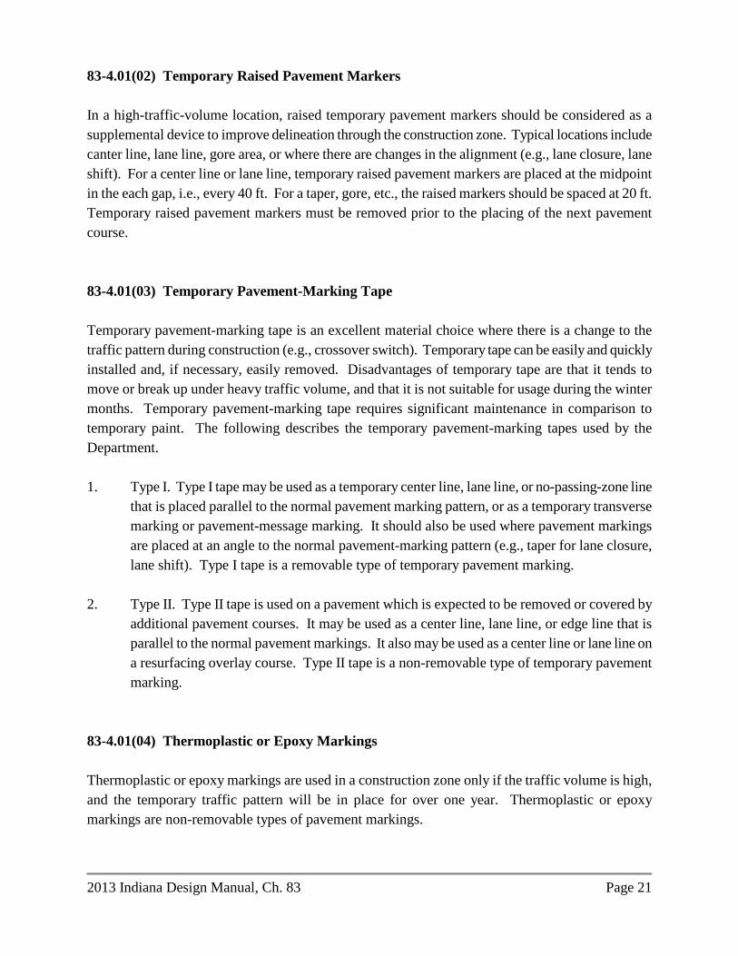
2013 Indiana Design Manual, Ch. 83 Page 21
83-4.01(02) Temporary Raised Pavement Markers In a high-traffic-volume location, raised temporary pavement markers should be considered as a supplemental device to improve delineation through the construction zone. Typical locations include canter line, lane line, gore area, or where there are changes in the alignment (e.g., lane closure, lane shift). For a center line or lane line, temporary raised pavement markers are placed at the midpoint in the each gap, i.e., every 40 ft. For a taper, gore, etc., the raised markers should be spaced at 20 ft. Temporary raised pavement markers must be removed prior to the placing of the next pavement course. 83-4.01(03) Temporary Pavement-Marking Tape Temporary pavement-marking tape is an excellent material choice where there is a change to the traffic pattern during construction (e.g., crossover switch). Temporary tape can be easily and quickly installed and, if necessary, easily removed. Disadvantages of temporary tape are that it tends to move or break up under heavy traffic volume, and that it is not suitable for usage during the winter months. Temporary pavement-marking tape requires significant maintenance in comparison to temporary paint. The following describes the temporary pavement-marking tapes used by the Department. 1. Type I. Type I tape may be used as a temporary center line, lane line, or no-passing-zone line
that is placed parallel to the normal pavement marking pattern, or as a temporary transverse marking or pavement-message marking. It should also be used where pavement markings are placed at an angle to the normal pavement-marking pattern (e.g., taper for lane closure, lane shift). Type I tape is a removable type of temporary pavement marking.
2. Type II. Type II tape is used on a pavement which is expected to be removed or covered by
additional pavement courses. It may be used as a center line, lane line, or edge line that is parallel to the normal pavement markings. It also may be used as a center line or lane line on a resurfacing overlay course. Type II tape is a non-removable type of temporary pavement marking.
83-4.01(04) Thermoplastic or Epoxy Markings Thermoplastic or epoxy markings are used in a construction zone only if the traffic volume is high, and the temporary traffic pattern will be in place for over one year. Thermoplastic or epoxy markings are non-removable types of pavement markings.

Page 22 2013 Indiana Design Manual, Ch. 83
83-4.01(05) Buzz Strips Buzz strips are used on a high-speed facility of 4 lanes or more in advance of a lane closure, alignment change, or stop condition to warn the motorist of the impending change. They are made with extruded material or repeated passes of pavement-marking tape to reach a ¼-in. height. Figure 83-4A illustrates the typical layout for buzz strips with a lane closure. The spacing criteria are also applicable to the other conditions listed above. 83-4.02 Application The application of temporary pavement markings in a construction zone depends on facility type, project duration, project length, and anticipated traffic volume. The phasing of temporary traffic control during construction should be considered. The temporary pavement markings should be selected that are best suited to the anticipated conditions and are most economical for the project. The removal of a removable temporary pavement marking is included in the removable-temporary-pavement-marking quantity. If non-removable markings that must be removed are selected as part of the planned traffic-maintenance plan, a quantity for removal of the non-removable markings is required. If non-removable temporary pavement markings are necessary on a final surface, placement of the temporary markings should be indicated to be as near as possible to the location of the final permanent pavement markings. 83-5.0 TEMPORARY TRAFFIC SIGNAL [Rev. Mar. 2016] 83-5.01 Location The use of a temporary traffic signal in a construction zone will be determined on a project-by-project basis. The warrant criteria for permanent installations in Section 502-3.02 should be used to help determine if a temporary traffic signal is warranted. However, the traffic volume expected during construction should be used for the warrant analysis. An Official Action, as described in Section 83-1.03, must be coordinated through the district traffic engineer. Locations where a temporary signal installation may be used include the following: 1. intersection where an existing signal must be maintained; 2. existing non-signalized intersection or drive where construction patterns and traffic volume
now warrant a signal;

2013 Indiana Design Manual, Ch. 83 Page 23
3. temporary haul road or other temporary access point; 4. long-term one lane, two-way traffic operation (e.g., bridge lane closure); or 5. crossroad or ramp intersection where there is an increase in traffic or there is a decrease in
capacity due to the construction. 83-5.02 Application [Rev. Mar. 2016] The designer should consider the following. 1. Existing Signals. The designer should determine the impacts that a construction activity
has on existing signal operations and should attempt to maximize the level-of-service. For example, the designer should consider the following:
a. recommend re-timing or re-phasing the signal to compensate for changes in traffic
volume, mix, or patterns, and for changes in lane designation or intersection-approach geometrics; and
b. physically relocating poles or adjusting signal heads to maintain compliance with
the IMUTCD. c. if temporary signals will be used, the designer should develop the signal timing
plan and show placement locations on the plans.
Section 502-3.0 and the IMUTCD provide design information for a traffic signal.
2. Bridge. If a lane is expected to be closed overnight, a temporary signal should be considered.
3. Type of Temporary Signal – One Lane, Two-Way Traffic Control. A temporary traffic
signal may either be fixed or portable, the type selected should be detailed on the plans and the appropriate pay item included in the cost estimate.
a. If a temporary traffic signal is chosen as an element of a temporary traffic control
plan the designer should consider whether it may be more cost effective to use a portable signal. Portable signals are mounted on trailers rather than wood poles and are generally rented by the contractor. When the need for a temporary traffic signal is expected to be less than six weeks, or the cost to bring electric service to

Page 24 2013 Indiana Design Manual, Ch. 83
the location is more than $10,000, portable traffic signals will typically be less expensive. Portable signals require a relatively flat area, approximately 8 ft by 8 ft in size, to accommodate the trailer. If necessary, a temporary landing area for the trailer may be constructed, using suitable material, on the side slope. If a temporary landing area is needed it should be shown on the plans.
b. In order to include the portable signal pay item into a contract the designer must
obtain concurrence from the district Traffic Office that the portable type is the best option. The Temporary Traffic Signal Type Determination form is available from the Department’s Editable Documents webpage, under Traffic Maintenance. The form should be submitted to the district Traffic Engineer as early as possible in the plan development process but at least prior to Stage 1 plan submittal.
4. Type of Temporary Signal - Intersection Traffic Control. In accordance with the
IMUTCD, Section 4D.32 temporary signals for intersection traffic control must be fixed. However, roads and drives within a one lane, two-way work zone may be controlled by portable signals.
5. Vehicle Detection. Whether fixed temporary or portable, the signal should include
vehicle detection. The detection area should be shown on the plans. See Figure 83-5A, Vehicle Detection Typical Placement Areas. The Standard Specifications allow the contractor to use either inductive loop or wireless detection for fixed temporary signals, but only wireless for portable. Where it is determined that another type of detection is needed, a unique special provision should be included in the contract.
6. Phasing/Timing Plans for Portable Signals. If portable signals will be used, the designer should develop the signal phasing and timing plan in accordance with the FHWA Signal Timing Manual and complete the Temporary Signal Timing Plan (RSP 801-T-212) and include this in the contract documents. a. For consultant designs the consultant shall be prequalified in Category 10.1,
Traffic Signal Design. b. For in-house projects the designer should discuss the phasing and timing plan with
district Traffic Engineer or the Systems Engineer in the Traffic Management Division.
c. Total cycle length should be limited to 255 seconds and the all red clearance
interval to 99 seconds. The following parameters may be used:

2013 Indiana Design Manual, Ch. 83 Page 25
i. Actuation should be provided and shown on the plans. See Figure 83-5A, Vehicle Detection Typical Placement Areas.
ii. The minimum green time for both phases is based on driver expectation and may be set at 15 seconds for major arterials regardless of speed and 10 seconds for minor arterials or collectors. The Signal Timing Manual allows for lower values based on engineering judgment (see Table 5-3).
iii. The maximum green time for each phase should be exceed the time it takes to clear a peak hour queue but should be limited to no more than 90 seconds for arterials and 40 seconds for collectors. This queue clearance time can be estimated by this equation: Gq = 3 + 2n where, Gq = green time to clear queue n = the number of vehicles in the queue To determine the number of vehicles in queue, the peak hour volume is divided by the number of cycles per hour so establishing Gq is an iterative process.
iv. Yellow change interval should be based on the approach speed. Yellow
change intervals on rural state highways may be set at 4 seconds for 40 mph and 5 seconds for 45 mph or greater.
v. All red clearance phase must be established by calculating the travel time
from signal to signal, which is the distance from signal to signal divided by the operating speed.
T = d ÷ avg. operating speed where, T = travel time for red clearance (seconds);
d = distance between signals (ft) avg. operating speed (ft/sec) = 1.467 x avg. operating speed (mph) The average operating speed through the work zone will depend on many conditions, e.g. truck volume, length of the work zone, lane width, shoulder width, offset to barriers, and pavement condition, but can be estimated at 25 mph.

Page 26 2013 Indiana Design Manual, Ch. 83
d. The designer should confirm that the anticipated queue will not encroach upon adjacent intersections. If encroachment is expected additional planning will be needed, e.g. the portable signal may need coordinated with the adjacent signal.
7. Plan Sheets. Show each temporary-signal installation, whether fixed or portable, in the traffic-maintenance plan. The placement locations for temporary signals should conform to the IMUTCD requirements for lateral and longitudinal signal positioning. For portable signals the designer should indicate if both signal heads must be mounted overhead.
8. Pay Items. A supplemental description noting the location, by intersection or route
number and reference post for one lane, two-way operations, must be included with the use of the fixed temporary signal or portable signal pay item. Vehicle detection is included in the cost of the pay item.
83-6.0 HIGHWAY LIGHTING 83-6.01 Types The lighting devices that are used in a construction zone are as follows: 1. hazard-identification beacons (flashing warning lights); 2. steady-burning warning lamps; 3. warning lights; 4. floodlights; and 5. conventional highway lighting. 83-6.02 Warrants Hazard-identification beacons, steady-burning electric lamps, and warning lights are used to supplement signs, barriers, or channelization devices, and emphasize specific signs, hazard areas, and the desired travel path. The warrants for lighting devices should satisfy the MUTCD. Floodlights are used to illuminate the work area during a nighttime operation (e.g., flagger station, equipment crossing, area requiring supplemental lighting). For conventional highway lighting, the need for temporary lighting will be determined on a project-by-project basis. Existing highway illumination should be maintained unless discontinuance of the highway illumination is specifically permitted. The warrants provided in Section 502-4.02 for permanent highway lighting should be reviewed to assist in determining the need for temporary

2013 Indiana Design Manual, Ch. 83 Page 27
lighting. The designer should consider the use of temporary lighting with the characteristics as follows: 1. high traffic volume; 2 high traffic speed; 3. heavy queuing or congestion; 4. area with complicated traffic maneuvers (e.g., freeway crossover, intersection); and 5. other area where a hazardous location may exist. If existing light standards are removed or if bulbs are shut off during construction, the designer should consider providing temporary lighting until permanent lighting is reinstalled. In a construction zone, the Department uses high-pressure sodium lamps mounted on temporary wood posts. However, the designer may consider portable lighting as an option. Section 502-4.0 provides additional information on the design of highway lighting.

English-Units
Value Metric-Units Equivalent
SPEED LIMIT 30 50
35 or 40 60 45 70 50 80 55 90
60 or 65 100 70 110
LONGITUDINAL DISTANCE 500 ft 150 m 1000 ft 300 m 1500 ft 450 m ¼ mi 400 m ½ mi 800 m 1 mi 1.5 km 2 mi 3 km
ENGLISH-TO-METRIC UNITS CONVERSION
Figure 83-2A

Existing Facility and Construction Type
Existing Posted Speed 50 mph 55 mph 65 mph
4-lane Interstate with crossover to a 2-lane
facility n/a
WZ 45 mph with TCB
WS 45 mph
WZ 55 mph with TCB
WS 45 mph
4-lane Interstate with lane closure without
a crossover n/a WS 45 mph
WZ 55 mph
WS 45 mph 6-lane Interstate with crossover to a 4-lane
facility with TCB WS 40 mph WS 45 mph
WZ 55 mph
WS 45 mph 6-lane Interstate with lane closure without
a crossover WS 40 mph WS 45 mph
WZ 55 mph
WS 45 mph
Non-Interstate divided highway with
crossover Project-by-project
WZ 45 mph with TTM & TDSYL
WS 45 mph
WZ 55 mph with TCB or TTM &
TDSYL. WS 45 mph
Non-Interstate divided highway with lane closure without
a crossover Project-by-project WS 45 mph
WZ 55 mph
WS 45 mph
Where:
WS = Work-Site Speed Limit (Indiana Statutes) WZ = Work-Zone Speed Limit (Official Action) TCB = Temporary Concrete Barrier n/a = Not Applicable TTM = Temporary Tubular Markers TDSYL = Temporary Double Solid Yellow Line
Note: Speed limit may vary based on circumstances and actual field conditions.
SUGGESTED DIVIDED-HIGHWAY SPEED LIMIT IN WORK ZONE OR WORK SITE
Figure 83-2B


Panel Type 1 Permitted Use Minimum Legibility
Distance 2
A Permitted on facility with speed lower than 35 mph. Appropriate for use on low-speed urban facility.
2600 ft
B Appropriate for intermediate-speed facility, or for maintenance or mobile operation on high-speed roadway. Not used by INDOT.
4000 ft
C Permitted on every facility. Appropriate for use on a high-speed, high-volume traffic-control project.
5200 ft
Notes: 1. For panel type, see the INDOT Standard Specifications and Federal MUTCD Part VI. 2. Minimum legibility distance under ideal day or night conditions.
SUGGESTED USE AND LOCATION OF FLASHING-ARROW SIGN
Figure 83-2D

LOCATION OF PCMS: MESSAGE TO BE DISPLAYED DURING MOT PHASE, EVENT, ETC.: CREATED BY: MESSAGE, PHASE 1
MESSAGE, PHASE 2
PROGRAMMING INFORMATION FOR PORTABLE CHANGEABLE MESSAGE SIGN
Figure 83-2E
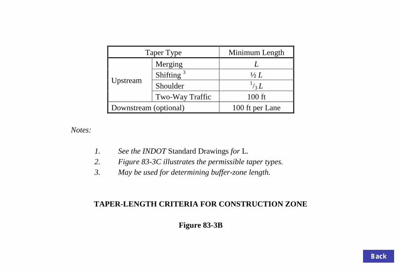
Taper Type Minimum Length
Upstream
Merging L Shifting 3 ½ L Shoulder 1/3 L Two-Way Traffic 100 ft
Downstream (optional) 100 ft per Lane Notes: 1. See the INDOT Standard Drawings for L. 2. Figure 83-3C illustrates the permissible taper types. 3. May be used for determining buffer-zone length.
TAPER-LENGTH CRITERIA FOR CONSTRUCTION ZONE
Figure 83-3B


Construction-Zone
Design Speed (mph)
Suggested Maximum Spacing (ft) Tapered Section
Tangent Section
25 * 20 * 40 30 30 60 35 35 70 40 40 80 45 45 90 50 50 100 55 55 110 60 60 120
* For a speed of 25 mph or lower, spacing should not be less than 20 ft.
SUGGESTED MAXIMUM SPACING OF CHANNELIZATION DEVICES
Figure 83-3D