Embed Size (px)
Citation preview
Trac-King In-Motion Satellite System#9760/9762
Installation and Operating Instructions
11200 Hampshire Avenue South, Bloomington, MN 55438-2453Phone: 800-982-9920 Fax: 952-922-8424
www.kingcontrols.com
1355 REV C
Satellite Solutions for Mobile Markets
KKIINNGGCCOONNTTRROOLLSS
Trac-King
®

Page 1
IMPORTANT!The satellite TV market is expanding and changing. The information in this manual wasaccurate at the time of printing. If your King-Dome does not operate as outlined in thismanual please call King Controls at 1-800-982-9920 or visit our website atwww.kingcontrols.com.
TABLE OF CONTENTS
Section Contents Page
1. INTRODUCTION.....................................................................................2
2. DEFINITION OF TERMS ........................................................................3
3. INSTALLATION..................................................................................4-13
4. OPERATION ....................................................................................14-17
5. TROUBLESHOOTING.....................................................................18-19
6. MAINTENANCE ....................................................................................20
7. LIMITED WARRANTY ..........................................................................21
DIRECTV® is an official trademark of DIRECTV, division of GM Hughes Electronics Corporation.Dish Network® is an official trademark of Echostar Communications Corporation.Bell ExpressVu® is an official trademark of Bell Canada.DVB® is a trademark of the DVB Digital Video Broadcast Project (1991-1996)
ELECTRICAL HAZARD WARNING!
The coaxial cable that connects the domeunit to the tuner carries a 30 volt electricalcurrent. Exercise extreme caution whenhandling this cable. Do not cut, break, orsplice this line. Do not insert or connectany devices such as splitters or any otherdevice for any reason. This line is notcompatible with any other equipment.Damage will occur to any device other thanthe dome unit if connected to the antennaport on the tuner.

Page 2
The Trac-King In-Motion Satellite System includes 4 main components. (Fig. 1)
Dome (Antenna) Unit Located on the roof of the vehicle. The dish is covered by aprotective dome that keeps operational components free fromthe elements.
Controller Located in the vehicle. Used to activate and monitor thesystem, and access programming and diagnostic information.
Tuner Located in the vehicle. Decodes the satellite signal so theTrac-King locks onto the correct satellite.
Power Supply Located in the vehicle. Supplies proper operating voltage tothe Trac-King.
SECTION 1 INTRODUCTION
Note: A TV, satellite receiver, and program subscription are also required for satellite TVviewing. (Not supplied by King Controls.)
Fig. 1
Note: For 9762 Dual In-Motion system see Pages 12-13.
KING-DOME Trac-King
START/STOP DISPLAYSELECT MODIFY

Page 3
AZIMUTH: Circular rotation around the vehicle.(like a clock face: front of vehicle is 12:00, rear is 6:00) (Fig. 2)
SIGNAL STRENGTH: Intensity of electronic signal received from the satellite transmission.
SECTION 2 DEFINITION OF TERMS
Fig. 2
Fig. 3
ELEVATION: Angle in degrees measured from the ground plane. (Fig. 3)

Page 4
SECTION 3 INSTALLATION
TOOLS AND MATERIALS REQUIRED:
- drill and drill bit set- tape measure- 7/16” open end wrench (coax connections)- adhesive sealant (compatible with roof material)- appropriate fasteners to install all components and wiring- 5/32” allen wrench, channel lock or pliers (to remove shipping bolt)- wire cutter (to remove shipping tie strap)
KIT CONTENTS:
1. Unpack and identify all components. (Fig. 4)
KING DOMEQUICK REFERENCE CARD
The Trac King has a variety ofoptions, settings, and informationavailabe via its display module.
Please review your owner’smanual for a more detailed
explanation. the display module isused to provide the system current
status and set your region, andselect your satellite.
Fig. 4

Page 5
Fig. 5
IMPORTANT! The tie strap, bolt and plastic spacers must be removed from the bottomof the dome unit prior to installation. DO NOT REMOVE THE DOMECOVER TO REMOVE THESE SHIPPING RESTRAINTS.
2. Remove and discard the tie strap, bolt and plastic spacers that pass through the bottomof the base. (Fig. 5)
IMPORTANT!Remove and
discard Bolt andPlastic Spacer prior
to installation.
IMPORTANT!Remove and discardTie Strap and Plastic
Spacer prior toinstallation.
Page 6
DOME LOCATION
3. Select an area on the roof for the dome unit and the location where the wiring will enterthe vehicle through the roof to the satellite receiver and internal components, using thefollowing criteria:
a) The shortest distance between the dome unit and the satellite receiver is mostdesirable.
a) The dome unit requires a 28 inch diameter circle.
b) The dome unit should be mounted on the centerline of the vehicle (side to side).
c) There must be no “line of sight” obstructions from this location. Air conditioningunits, other antennas, and storage areas that are too close to the dome unit mayprevent the satellite signal from reaching the dish. (Fig. 6)
HEIGHT OFOBSTRUCTION
APPROXIMATE MINIMUM DISTANCE
TO DOME EDGE10” 8”11” 10”12” 12”13” 14”14” 16”
15” 18”
16” 20”
Fig.6
IMPORTANT! For installations on trucks with air shields, a bracket must be used formounting the dome unit. The dome unit MUST be mounted to the air ridecab: NEVER to any structure mounted directly to the frame.
See bracket instructions for proper installation. (Fig. 7)

Page 7
Fig. 7
IMPORTANT! The dome unit MUST be mounted to the air ride cab: NEVER toany structure mounted directly to the frame.
4. Place dome unit on installation location chosen using the criteria discussed in theprevious section. Shipping restraints must be removed (Fig. 5, Page 5), and cableconnection must be positioned facing rear of vehicle.
5. The dome unit must be positioned so that both feet on each side of the vehicle are equaldistances from the roof edge. This should be checked by measuring the distance fromeach foot to the roof edge. Confirm that these measurements are equal. (Fig. 8)
IMPORTANT! Make sure shipping restraints are removed from bottom of dome unit. (Fig. 5, Page 5)
Cable connection must ALWAYS be positioned facing the rear of vehicle.
Fig. 8
DOME INSTALLATION
IMPORTANT! The dome should never be mounted so that it istilted more than two degrees in any direction.
Example of truck installation using bracket. See bracket instructions for proper installation.

Page 8
Note: The installer is responsible for determining the most appropriate fastener to secure thedome unit to the roof. Depending on the roof material, fasteners such as lag screws,well nuts, sheet metal screws, toggle bolts and T anchors may be used, and shouldalways be used in combination with a roof compatible sealant.
The installer is responsible for weatherproofing all holes with sealant.
6. Mount the dome unit. Use the pre-drilled holes in the mounting feet as a guide to installthe fasteners into the roof. Use additional fasteners whenever necessary.
7. Test that the dome unit is secure by pulling upward from each foot location.
EXTERNAL WIRING
8. Connect 35’ coax cable to the coax port located on the back of the dome unit and tightenconnection. Do not over tighten coax connection. (Fig. 9)
9. Snap the gel-filled boot around the coax connection. (Fig. 9)
Fig. 9
IMPORTANT! Coax connection should be snug. DO NOT OVER TIGHTEN!

Page 9
10. Run coax from the dome unit to the roof edge, then along edge to location where coaxwill be fed into the vehicle. Secure coax to roof every 12-18 inches. (Fig. 10)
11. Drill 1/2” hole through the roof and into the cabinet where receiver is stored. Feed coaxdown through hole. Seal opening with roof compatible sealant so that it is entirelywaterproof (inside and outside of the 1/2” hole). (Fig. 10)
12. Remove blue protective sheet and red “position to rear” sticker from the dome unit.
Fig. 10 TYPICAL ROOF INSTALLATION - OVERHEAD VIEW
IMPORTANT!Sealant must
be roofcompatible.
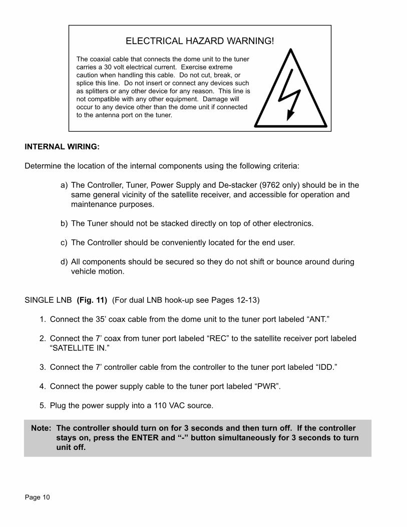
ELECTRICAL HAZARD WARNING!
The coaxial cable that connects the dome unit to the tunercarries a 30 volt electrical current. Exercise extremecaution when handling this cable. Do not cut, break, orsplice this line. Do not insert or connect any devices suchas splitters or any other device for any reason. This line isnot compatible with any other equipment. Damage willoccur to any device other than the dome unit if connectedto the antenna port on the tuner.
Page 10
INTERNAL WIRING:
Determine the location of the internal components using the following criteria:
a) The Controller, Tuner, Power Supply and De-stacker (9762 only) should be in thesame general vicinity of the satellite receiver, and accessible for operation andmaintenance purposes.
b) The Tuner should not be stacked directly on top of other electronics.
c) The Controller should be conveniently located for the end user.
d) All components should be secured so they do not shift or bounce around duringvehicle motion.
SINGLE LNB (Fig. 11) (For dual LNB hook-up see Pages 12-13)
1. Connect the 35’ coax cable from the dome unit to the tuner port labeled “ANT.”
2. Connect the 7’ coax from tuner port labeled “REC” to the satellite receiver port labeled“SATELLITE IN.”
3. Connect the 7’ controller cable from the controller to the tuner port labeled “IDD.”
4. Connect the power supply cable to the tuner port labeled “PWR”.
5. Plug the power supply into a 110 VAC source.
Note: The controller should turn on for 3 seconds and then turn off. If the controllerstays on, press the ENTER and “-” button simultaneously for 3 seconds to turnunit off.

Page 11
SINGLE LNB HOOK-UPFig. 11
IMPORTANT! AVOID SHARP BENDS WHEN ROUTING COAX.

Page 12
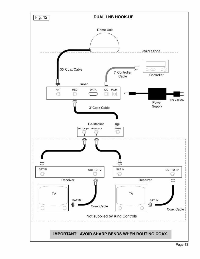
DUAL LNB (Fig. 12)
1. Connect the 35’ coax cable from the dome unit to the tuner port labeled “ANT.”
2. Connect the 3’ coax from the tuner port labeled “REC” to the de-stacker port labeled“INPUT.”
3. Connect the 7’ controller cable from the controller to the tuner port labeled “IDD.”
4. Connect the port on the de-stacker labeled “IRD Output 1” to the “SAT IN” port on the firstsatellite receiver. Connect the port on the de-stacker labeled “IRD Output 2” to the “SATIN” port on the second receiver.
5. Connect the power supply cable to the tuner port labeled “PWR”.
6. Plug the power supply into a 110 VAC source.
Note: The controller should turn on for 3 seconds and then turn off. If the controllerstays on, press the ENTER and “-” button simultaneously for 3 seconds to turnunit off.
ELECTRICAL HAZARD WARNING!
The coaxial cable that connects the dome unit to the tunercarries a 30 volt electrical current. Exercise extremecaution when handling this cable. Do not cut, break, orsplice this line. Do not insert or connect any devices suchas splitters or any other device for any reason. This line isnot compatible with any other equipment. Damage willoccur to any device other than the dome unit if connectedto the antenna port on the tuner.
Page 13
DUAL LNB HOOK-UPFig. 12
IMPORTANT! AVOID SHARP BENDS WHEN ROUTING COAX.

Page 14
1. Turn ON the TV and satellite receiver. “Searching for Satellite Signal” or similar shouldappear on the TV.
IMPORTANT! There must be a clear “line of sight” to the southern sky. Mountains,buildings, trees, telephone poles, etc. can all block the satellite signalfrom reaching the dish.
SECTION 4 OPERATION
2. Press Trac-King powers up, performs a selfdiagnostic and loads software.
Trac-King begins searching for indicated satellite in the indicated region.
Trac-King has locked onto indicatedsatellite in indicated region.
ONPOWERING UPPLEASE WAIT
LOADINGPLEASE WAIT
RUN: SCAN ALIGNNOW ON?
RUN: SCAN ALIGN2-NORTH CENTRAL
RUN: SCAN ALIGNDTV 101
RUN: LOCKED S XXNOW ON 101
RUN: LOCKED S XXDTV 101
RUN: LOCKED S XX2- NORTH CENTRAL

SET REGION
1. Press
2. Press
3. Press
4. Press
or
5. Press
6. Press
Page 15
ON
ON
MAIN
ENTER
+
-
Unit goes into IDLE/HOLD mode.
Unit goes into USER SETUP menu.
Unit goes into SET REGION menu.
Find your location on the map below anddetermine which region you are in. Usethe plus and minus buttons to display yourregion on the controller.
Sets REGION in memory.
Unit searches based on new REGION.
REGION OPTIONS:
1 NORTH WEST2 NORTH CENTRAL3 NORTH EAST4 CENTRAL WEST5 MIDDLE CENTRAL6 CENTRAL EAST7 SOUTH WEST8 SOUTH CENTRAL9 SOUTH EAST
ALL REGIONS0 RECALIBRATE
IDLE/HOLD
USER SETUPrev xxxx sn xxxxx
SET REGIONXXXXXXXXXXXX
Display your region on the controller
IDLE/HOLD
RUN: SCAN ALIGN
Note: To reduce satellite acquisition time, you can set your current region.
Page 16
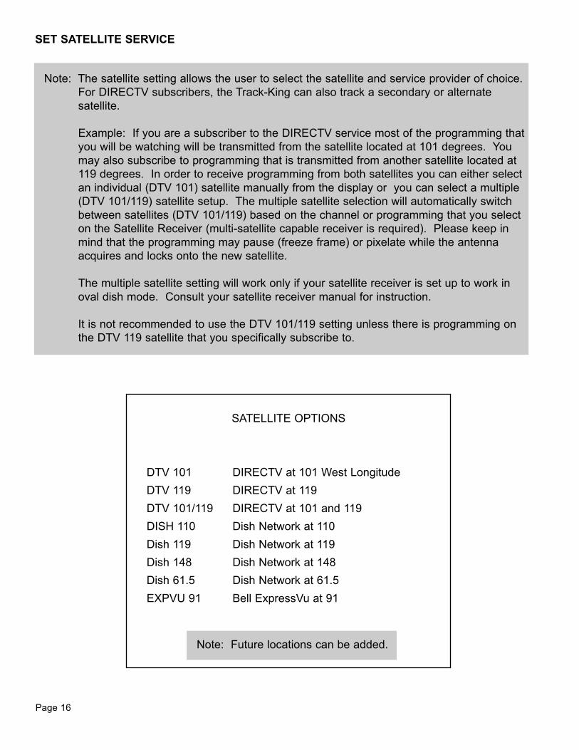
Note: The satellite setting allows the user to select the satellite and service provider of choice.For DIRECTV subscribers, the Track-King can also track a secondary or alternatesatellite.
Example: If you are a subscriber to the DIRECTV service most of the programming thatyou will be watching will be transmitted from the satellite located at 101 degrees. Youmay also subscribe to programming that is transmitted from another satellite located at119 degrees. In order to receive programming from both satellites you can either selectan individual (DTV 101) satellite manually from the display or you can select a multiple(DTV 101/119) satellite setup. The multiple satellite selection will automatically switchbetween satellites (DTV 101/119) based on the channel or programming that you selecton the Satellite Receiver (multi-satellite capable receiver is required). Please keep inmind that the programming may pause (freeze frame) or pixelate while the antennaacquires and locks onto the new satellite.
The multiple satellite setting will work only if your satellite receiver is set up to work inoval dish mode. Consult your satellite receiver manual for instruction.
It is not recommended to use the DTV 101/119 setting unless there is programming onthe DTV 119 satellite that you specifically subscribe to.
SET SATELLITE SERVICE
SATELLITE OPTIONS
DTV 101 DIRECTV at 101 West LongitudeDTV 119 DIRECTV at 119DTV 101/119 DIRECTV at 101 and 119DISH 110 Dish Network at 110Dish 119 Dish Network at 119Dish 148 Dish Network at 148Dish 61.5 Dish Network at 61.5EXPVU 91 Bell ExpressVu at 91
Note: Future locations can be added.

Page 17
1. Press
2. Press
or
3. Press ENTER
+
-
Unit goes into SET SATELLITE menu.
Use the plus and minus buttons to displayyour desired satellite on the controller.
Sets SATELLITE in memory.Unit searches for new designated satellite.
SET SATELLITE-----?-----
Display desired satellite on controller
RUN: SWITCHING
Note: The Trac-King must remain turned on to maintain a signal. If you are going to bestationary and wish to continue watching TV, do not turn the system off.
Press ON to put the system into “IDLE/HOLD” mode.
In “IDLE/HOLD” mode, the system cannot track the satellite when the vehicle is inmotion.
Before moving the vehicle, press ON to put the system back into “RUN” mode.

Page 18
SECTION 5 TROUBLESHOOTING
Controller does not power up. Check: tuner is connected to power supply.
controller is connected to tuner.
power supply is plugged into live outlet
Display reads “AZ ERROR” Dish cannot rotate.
Make sure shipping restraints are removed.
Controller remains in “POWER UP, PLEASEWAIT” condition.
No communication between tuner and domeunit.
Check for 24 volts coming out of tuner to domeunit.
Check for 24 volts at dome unit end of 35’ coax.
Display reads “EL ERROR” Dish stuck on limit switch.
Restart system. If problem persists, perform 0-RECALIBRATE. (See Page 19)

Page 19
Unit will not lock on satellite, or drifts off satellite,
Satellite signal is blocked from reaching unit. Movevehicle to have unobstructed view of southern sky.
Software needs rebooting. Perform Option21 Reboot and0-RECALIBRATION.
OPTION 21 REBOOT and 0-RECALIBRATE
1. Press MAIN 2 times to enter DEALER SETUPmenu.
2. Press “+” 13 times to scroll up to CODE 13.
3. Press ENTER.
4. Press 2 times to enter SET OPTION menu.
5. Press “-” 10 times to scroll down to OPTION 21.
6. Press ENTER to reinitialize software.
7. Wait unitl dispaly shows “Option 0” then press MAINto return to main page.
8. Press ENTER and “-” simultaneously to shut systemoff.
9. Unplug data cable from controller for 10 secondsand then plug back in.
10. Wait until controller shows “off” then press ON tostart system.
11. Press ON to enter IDLE/HOLD mode.
12. Press MAIN to enter USER SETUP menu.
13. Press to enter SET REGION menu.
14. Press “-” 5 times to scroll down to 0-RECALIBRATE.
15. Press ENTER. System returns to IDLE/HOLD modeand is ready to run recalibration.
16. Press ON. System recalibrates gyros (may take upto 10 minutes) and continues search in previouslyset region.
Note: If OPTION 21 REBOOT and0-RECALIBRATE do notsolve the problem, replacethe 35’ coax and repeatprocedure.

Page 20
The King-Dome Satellite System has been designed to be maintenance and trouble free.
For optimum signal strength, keep the dome clean from dirt, bugs, and other debris. Periodicwashing of the dome with mild soap and water is recommended.
If you plan on storing your vehicle for long periods of time, it is recommended that the system beput through a search procedure on a quarterly basis to keep all moving parts in good workingorder.
If you have any comments or questions, please contact the King Controls Service Department at1-800-982-9920, or email King Controls at [email protected]
SECTION 6 MAINTENANCE

Page 21
Every King Controls Satellite System is thoroughly inspected and tested before leaving the factory. It is covered bya two year parts and one year labor limited warranty from the date of original purchase. This warranty does notcover installation and external wiring or refurbished units.
Should any trouble develop during the warranty period, contact King Controls or one of its certified dealers. OnlyKing Controls and certified dealers are authorized to perform warranty evaluations and repairs.
If it is determined that the unit needs to be returned, return COMPLETE product, freight prepaid, to : King Controls, 5100 West 36th Street, St. Louis Park, MN 55416. If inspection shows the trouble is caused bydefective workmanship or material, King Controls will repair (or at its option, replace) without charge.
This warranty does not apply where:
- The product has been abused, misused, improperly installed or improperly maintained.- Repairs have been made or attempted by others that are not certified by King Controls to do such repairs.- Repairs are required because of normal wear and tear.- Alterations have been made to the product.- Unit has been sold by original owner.
In no event shall King Controls be liable for any indirect, incidental, or consequential damages from thesale or use of the product. This disclaimer applies both during and after the term of the warranty.
King Controls disclaims liability for any implied warranties, including implied warranties of“merchantability” and “fitness for a specific purpose,” after the one year term of this warranty.
This warranty gives you specific legal rights, and you may also have other rights, which vary from state to state.Some states do not allow the exclusion or limitation of incidental or consequential damages, so the above limitationor exclusion may not apply to you. Some states do not allow limitations on how long an implied warranty lasts, sothe above limitation may not apply to you.
SECTION 7 LIMITED WARRANTY
11200 Hampshire Avenue South, Bloomington, MN 55438-2453Phone: 800-982-9920 Fax: 952-922-8424
www.kingcontrols.com
Trac-King
®