Embed Size (px)
DESCRIPTION
R1049 Configure vSphere SW iSCSI with PS Series SAN v1 2.pdf
Citation preview
TECHNICAL REPORT
Configuring VMware vSphere Software iSCSI
With Dell EqualLogic PS Series Storage
ABSTRACT
This Technical Report will explain how to configure and
connect a Dell™ EqualLogic™ PS Series SAN to VMware®
vSphere™ using the software iSCSI initiator.
TR1049
V1.2

Copyright © 2010 Dell Inc. All Rights Reserved.
Dell EqualLogic is a trademark of Dell Inc.
All trademarks and registered trademarks mentioned herein are the property of their respective owners.
Possession, use, or copying of the documentation or the software described in this publication is authorized only under the
license agreement specified herein.
Dell, Inc. will not be held liable for technical or editorial errors or omissions contained herein. The information in this
document is subject to change.
[Nov 2010]
WWW.DELL.COM/PSseries
PREFACE
Thank you for your interest in Dell EqualLogic™ PS Series storage products. We hope you will find the PS Series products intuitive
and simple to configure and manage.
PS Series arrays optimize resources by automating volume and network load balancing. Additionally, PS Series arrays offer all-
inclusive array management software, host software, and free firmware updates. The following value-add features and products
integrate with PS Series arrays and are available at no additional cost:
PS Series Array Software
o Firmware – Installed on each array, this software allows you to manage your storage environment and provides
capabilities such as volume snapshots, clones, and replicas to ensure data hosted on the arrays can be protected in the
event of an error or disaster.
Group Manager GUI: Provides a graphical user interface for managing your array
Group Manager CLI: Provides a command line interface for managing your array.
o Manual Transfer Utility (MTU): Runs on Windows and Linux host systems and enables secure transfer of large
amounts of data to a replication partner site when configuring disaster tolerance. You use portable media to eliminate
network congestion, minimize downtime, and quick-start replication.
Host Software for Windows
o Host Integration Tools
Remote Setup Wizard (RSW): Initializes new PS Series arrays, configures host connections to PS Series
SANs, and configures and manages multipathing.
Multipath I/O Device Specific Module (MPIO DSM): Includes a connection awareness-module that
understands PS Series network load balancing and facilitates host connections to PS Series volumes.
VSS and VDS Provider Services: Allows 3rd
party backup software vendors to perform off-host backups.
Auto-Snapshot Manager/Microsoft Edition (ASM/ME): Provides point-in-time SAN protection of critical
application data using PS Series snapshots, clones, and replicas of supported applications such as SQL Server,
Exchange Server, Hyper-V, and NTFS file shares.
o SAN HeadQuarters (SANHQ): Provides centralized monitoring, historical performance trending, and event reporting
for multiple PS Series groups.
Host Software for VMware
o Storage Adapter for Site Recovery Manager (SRM): Allows SRM to understand and recognize PS Series replication
for full SRM integration.
o Auto-Snapshot Manager/VMware Edition (ASM/VE): Integrates with VMware Virtual Center and PS Series
snapshots to allow administrators to enable Smart Copy protection of Virtual Center folders, datastores, and virtual
machines.
o Multipathing Extension Module for VMware® vSphere: Provides connection awareness enhancements to the
existing VMware multipathing functionality that understands PS Series network load balancing and facilitates host
connections to PS Series volumes.
Current Customers Please Note: You may not be running the latest versions of the tools and software listed above. If you are under
valid warranty or support agreements for your PS Series array, you are entitled to obtain the latest updates and new releases as they
become available.
To learn more about any of these products, contact your local sales representative or visit the Dell EqualLogic™ site at
http://www.equallogic.com. To set up a Dell EqualLogic support account to download the latest available PS Series firmware and
software kits visit: https://www.equallogic.com/secure/login.aspx
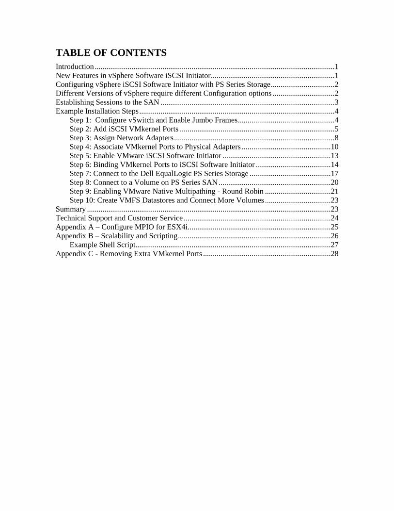
TABLE OF CONTENTS
Introduction ............................................................................................................................ 1 New Features in vSphere Software iSCSI Initiator................................................................ 1
Configuring vSphere iSCSI Software Initiator with PS Series Storage ................................. 2 Different Versions of vSphere require different Configuration options ................................ 2 Establishing Sessions to the SAN .......................................................................................... 3 Example Installation Steps ..................................................................................................... 4
Step 1: Configure vSwitch and Enable Jumbo Frames .................................................. 4
Step 2: Add iSCSI VMkernel Ports ................................................................................ 5 Step 3: Assign Network Adapters ................................................................................... 8 Step 4: Associate VMkernel Ports to Physical Adapters .............................................. 10 Step 5: Enable VMware iSCSI Software Initiator ........................................................ 13
Step 6: Binding VMkernel Ports to iSCSI Software Initiator ....................................... 14 Step 7: Connect to the Dell EqualLogic PS Series Storage .......................................... 17 Step 8: Connect to a Volume on PS Series SAN .......................................................... 20
Step 9: Enabling VMware Native Multipathing - Round Robin .................................. 21 Step 10: Create VMFS Datastores and Connect More Volumes .................................. 23
Summary .............................................................................................................................. 23 Technical Support and Customer Service ............................................................................ 24 Appendix A – Configure MPIO for ESX4i.......................................................................... 25
Appendix B – Scalability and Scripting ............................................................................... 26 Example Shell Script..................................................................................................... 27
Appendix C - Removing Extra VMkernel Ports .................................................................. 28
iii
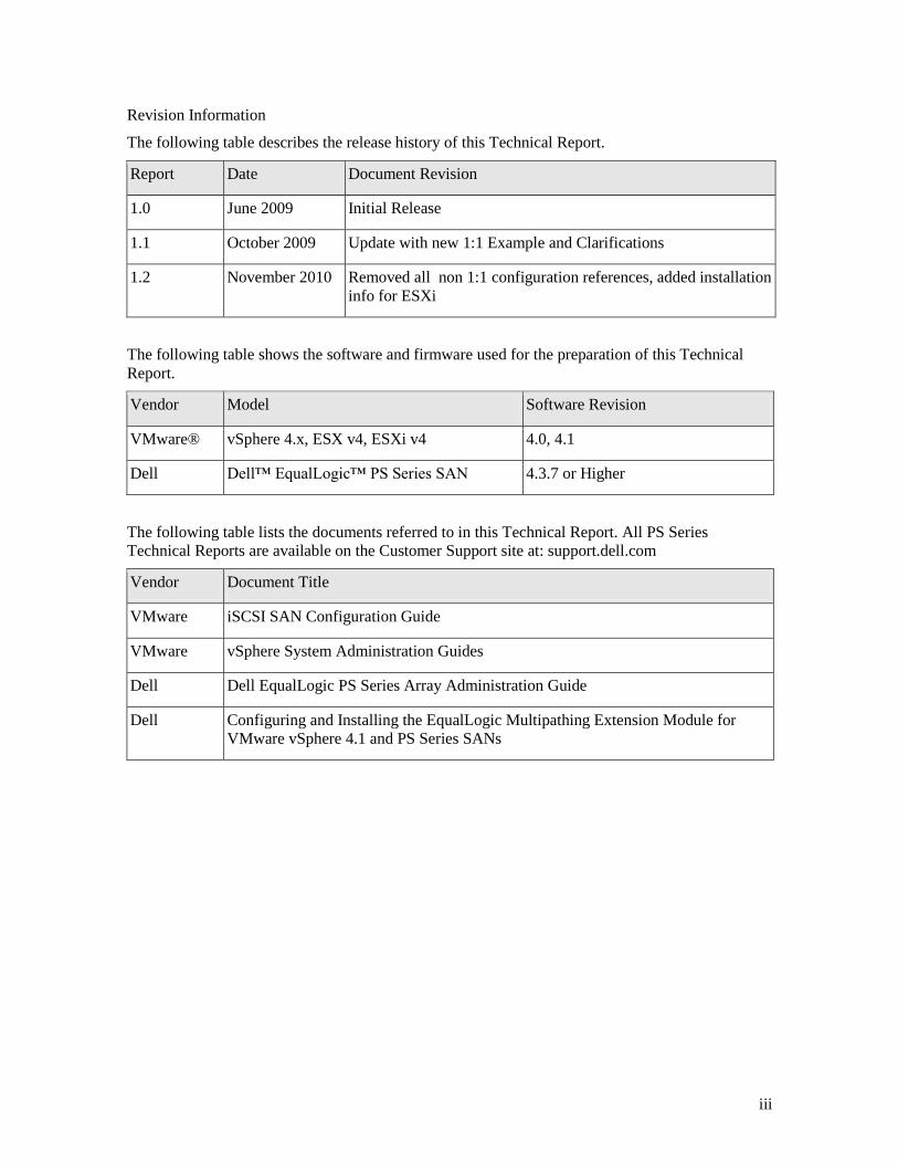
Revision Information
The following table describes the release history of this Technical Report.
Report Date Document Revision
1.0 June 2009 Initial Release
1.1 October 2009 Update with new 1:1 Example and Clarifications
1.2 November 2010 Removed all non 1:1 configuration references, added installation
info for ESXi
The following table shows the software and firmware used for the preparation of this Technical
Report.
Vendor Model Software Revision
VMware® vSphere 4.x, ESX v4, ESXi v4 4.0, 4.1
Dell Dell™ EqualLogic™ PS Series SAN 4.3.7 or Higher
The following table lists the documents referred to in this Technical Report. All PS Series
Technical Reports are available on the Customer Support site at: support.dell.com
Vendor Document Title
VMware iSCSI SAN Configuration Guide
VMware vSphere System Administration Guides
Dell Dell EqualLogic PS Series Array Administration Guide
Dell Configuring and Installing the EqualLogic Multipathing Extension Module for
VMware vSphere 4.1 and PS Series SANs

1
INTRODUCTION
VMware® vSphere™ offers many new and advanced enhancements to the iSCSI software initiator
in conjunction with iSCSI SAN connectivity. Many of these new features require advanced
configuration in order to work properly. Administrators who are familiar with ESX 3.5 iSCSI SAN
configuration may find that their current configuration steps are not sufficient to enable all of the
advanced features offered in vSphere.
This Technical Report will attempt to address some of the new features in vSphere as well as show
you how to connect a vSphere environment to a Dell™ EqualLogic™ PS Series iSCSI SAN.
These steps are documented in VMware’s iSCSI SAN Configuration Guide which can be found on
VMware’s website but this Technical Report will go into depth on configuration steps for
connecting to a PS Series SAN.
This Technical Report will cover the steps for utilizing the software iSCSI initiator inside the ESX
server. Users connecting their vSphere environment using just iSCSI HBAs or users wishing to
only assign a single iSCSI NIC with no Jumbo Frame support will not follow these steps and
configure their environment in the same manner as ESX 3.x. Users who wish to only enable
Jumbo Frame support for their environment will want to take note of steps 1 and 2 but only create a
single VMkernel port through the vCenter GUI after that.
NEW FEATURES IN VSPHERE SOFTWARE ISCSI INITIATOR
VMware vSphere ESX 4.X has new support for various new advanced capabilities that were not
found in ESX 3.5. This Technical Report will cover the new features in the iSCSI software
initiator as well as how to configure them to connect to the SAN.
iSCSI Software Initiator – With ESX 4.X, the iSCSI software initiator was re-written
from the ground up for better performance and functionality.
Jumbo Frames – With ESX 4.X and vSphere, Jumbo Frames can be enabled on the iSCSI
software initiator. Jumbo Frame support allows for larger packets to be transferred
between the ESX 4.X servers and the SAN for increased efficiency and performance.
Presently, Jumbo Frame Support can only be enabled via CLI commands with ESX 4.0.
Note: Jumbo Frames are not required, they’re optional. Your network infrastructure must
be able to fully support them to achieve any benefit.
MPIO – With ESX 4.X and vSphere, customers can benefit from Multi-Path I/O from the
ESX 4.X server and the SAN. This allows for multiple connections to be concurrently
used to allow for greater bandwidth. This is especially important for the PS Series SAN as
each PS Series member has multiple connections and now ESX 4.X can take full advantage
of these.
Third Party MPIO Support – With ESX 4.1, VMware has provided an architecture that
enables storage vendors to provide new and advanced intelligent integration. Dell has a
new MPIO plug-in that will enhance MPIO with the existing iSCSI software initiator for
easier management, better performance and bandwidth.
2
CONFIGURING VSPHERE ISCSI SOFTWARE INITIATOR WITH PS SERIES
STORAGE
Taking advantage of all of these new features requires some new steps to be taken by ESX
administrators. Most of the configuration is done via CLI inside the ESX server. At the release of
this document there are plans to implement many of these steps into vCenter but currently a
majority of the work is done via console commands. The rest of this Technical Report will be
focusing on installation and configuration of an iSCSI software initiator connection to a PS Series
SAN. Each of these commands can be found inside the VMware iSCSI SAN configuration guide
and where names and IP Addresses are used, they will be different for each environment. This is
merely an example and demonstration of how to configure a new vSphere ESX 4.X server
correctly and connect it to the PS SAN.
The following assumptions are made for this example:
1. Running ESX 4.X
2. Running Dell EqualLogic PS Series SAN Firmware 4.3.7 or later
3. More than one Network Interface Card (NIC) set aside for iSCSI traffic
4. No Distributed Virtual Switch (DVS) nor Cisco Nexus 1000v for iSCSI traffic
Not every environment will require all of the steps detailed in this Technical Report.
Users wishing to only enable Jumbo Frame support for the iSCSI connection need to read and
follow steps 1 and steps 2 with the following changes:
Step 1: Configure vSwitch and Enable Jumbo Frames – No changes to the instructions
Step 2: Add iSCSI VMkernel Ports – Instead of assigning multiple VMkernel Ports, administrators
will only assign a single VMkernel Port
Once these two steps are done, the rest of the configuration can be accomplished in the vCenter
GUI by attaching NICs, assigning storage and then connecting to the storage.
The rest of this document assumes the environment will be using multiple NICs and attaching to a
Dell EqualLogic PS Series SAN utilizing Native Multipathing (NMP) from VMware.
DIFFERENT VERSIONS OF VSPHERE REQUIRE DIFFERENT
CONFIGURATION OPTIONS
With the release of vSphere 4.1, 3rd
party vendors are able to employ Multipathing modules. Dell
has released the Multipathing Extension Module (MEM) for vSphere 4.1 but it can only be used in
certain environments. Here is a handy reference for which versions of Multipathing steps can be
used along with some general minimum requirements.
vSphere 4.0
Patch 5 or Update 2 Required (iSCSI connection drops on same subnet)
Patch ESX400-201009401-SG KB#1023759
1:1 VMkernel to physical nic binding as described in this document
Follow TR1049 (This document) on how to configure MPIO and iSCSI connectivity
vSphere 4.1 with Enterprise or Enterprise Plus License
Dell recommends installing and configuring the Dell EqualLogic Multipathing Extension Module
(MEM)
3
Follow TR1048 Configuring and Installing the EqualLogic Multipathing Extension Module for
VMware vSphere 4.1 and PS Series SANs for more information on how to configure the MEM and
iSCSI configuration. The MEM also has a convenient setup script that will automate a majority of
the CLI command tasks that were needed in vSphere 4.0
vSphere 4.1 without Enterprise or Enterprise Plus License
1:1 VMkernel to physical nic binding as described in this document
Even if you do not have Enterprise or Enterprise Plus license, you can still utilize the setup.pl script
found in the EqualLogic Multipathing Extension module to help automate the iSCSI configuration
process. This information can be found in TR1048 and even without the installation of the MEM it
can assist in helping automate the configuration of iSCSI Multipathing.
Follow TR1049 (This document) on how to configure MPIO and iSCSI connectivity if you are not
using the MEM setup script.
ESTABLISHING SESSIONS TO THE SAN
Before continuing, we first must discuss how VMware ESX establishes its connection to the SAN
utilizing the new vSphere iSCSI Software Adapter. VMware uses VMkernel ports as the session
initiators so we must configure each port that we want to use as a path to the storage. This
configuration will be a one to one relationship. Each session to the SAN will come from one
vmkernel port which will go out a single physical nic. Once these sessions to the SAN are
initiated, both the VMware NMP and the Dell EqualLogic network load balancer will take care of
load balancing and spreading the I/O across all available paths.
Each volume on the PS Series array can be utilized by ESX as either a Datastore or a Raw Device
Map (RDM). To do this, the iSCSI software adapter utilizes the VMkernel ports that were created
and establishes a session to the SAN and to that volume to communicate. With previous versions
of ESX, this session was established using a single NIC path and any additional NICs were there
for failover only. With the improvements to vSphere and MPIO, administrators can now take
advantage of multiple paths to the SAN for greater bandwidth and performance. This does require
some additional configuration which is discussed in detail in this Technical Report.
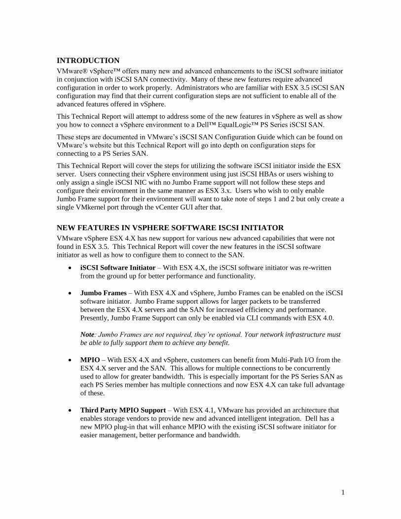
Each VMkernel is bound to a physical adapter. Depending on the environment this can create a
single session to a volume or up to 8 sessions (ESX maximum number of connections per volume).
Use a one to one (1:1) ratio of VMkernels to physical network cards. This means if there are 3
physical NICs, you would establish 1 VMkernel per physical NIC and associate a separate NIC
with each VMkernel port. This means in this example you would establish 3 sessions to a single
volume on the SAN. This trend can be expanded depending on the number of NICs you have in
the system.
4
Figure 1: Conceptual Image of iSCSI Sessions using 1:1 VMkernel mapping with
physical NICs
EXAMPLE INSTALLATION STEPS
Each environment will be different but the following is a list of example installation steps to
configure a new ESX 4.X host to a PS Series SAN. Throughout these examples the names and IP
addresses assigned will need to be changed to be relevant in your environment. These examples
assume a vSwitch with Jumbo Frame support on the physical hardware. All commands are case
sensitive and can be found in their full context in the VMware iSCSI SAN Configuration Guide.
This Technical Report will focus on one to one (1:1) VMkernel mapping with 3 physical NICs and
3 VMkernels. This would be a typical solution for many environments to utilize all of the
bandwidth available to the ESX server’s network interfaces.
Step 1: Configure vSwitch and Enable Jumbo Frames
This step will create a new vSwitch and enable Jumbo Frame support for this switch. Currently
there is no option to enable Jumbo Frames on a vSwitch from VMware vCenter GUI so these
commands must be run via CLI. Be sure to check the environment to make sure that Jumbo
Frames are supported at the networking layer before enabling it on the ESX host. These commands
are run either from the ESX console or if running ESX 4.xi from RCLI or VMA. For more
information on using remote configuration calls see Appendix A.
The following command will create a new vSwitch called vSwitch2:
#esxcfg-vswitch –a vSwitch2
Next, enable Jumbo Frames on the vSwitch:
#esxcfg-vswitch –m 9000 vSwitch2
To verify that the switch was configured properly run the following command:
#esxcfg-vswitch –l
Your output will look similar to this:
Switch Name Num Ports Used Ports Configured Ports MTU
Uplinks
vSwitch2 64 1 64 9000
5
PortGroup Name VLAN ID Used Ports Uplinks
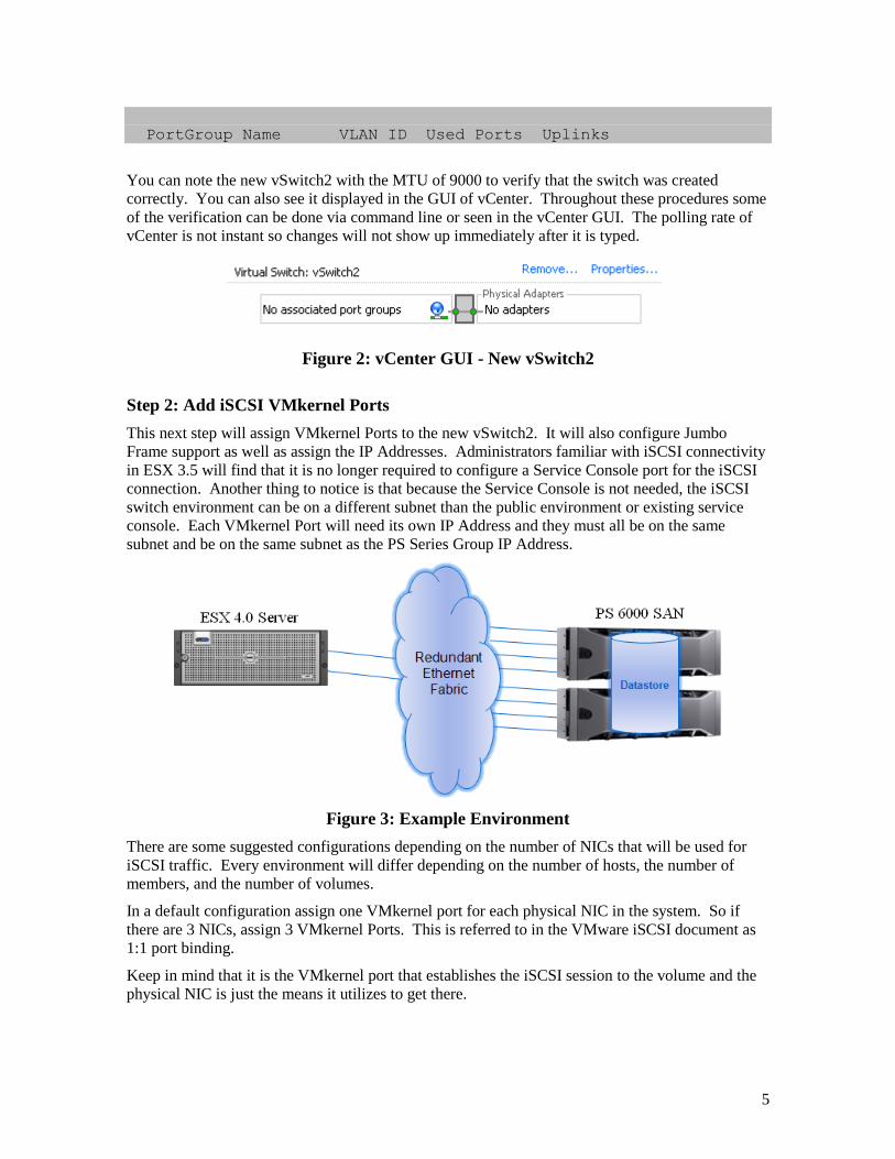
You can note the new vSwitch2 with the MTU of 9000 to verify that the switch was created
correctly. You can also see it displayed in the GUI of vCenter. Throughout these procedures some
of the verification can be done via command line or seen in the vCenter GUI. The polling rate of
vCenter is not instant so changes will not show up immediately after it is typed.
Figure 2: vCenter GUI - New vSwitch2
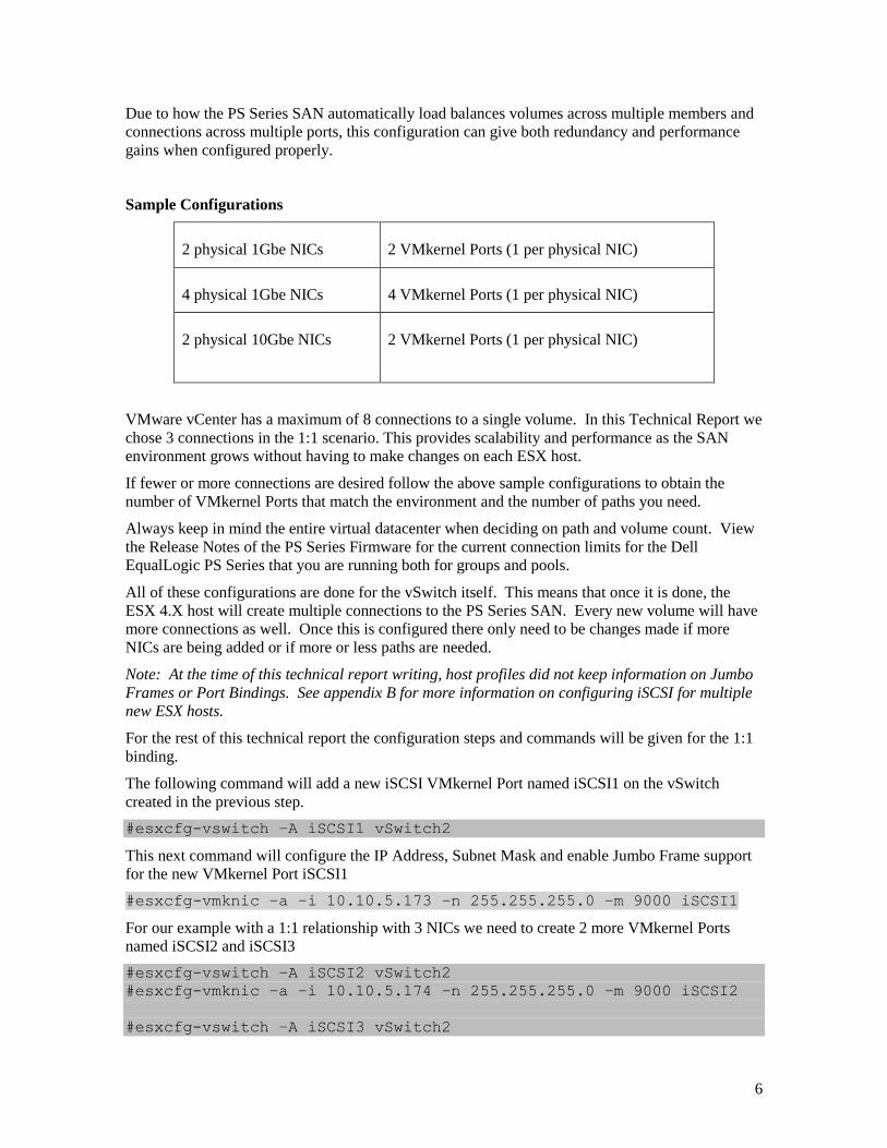
Step 2: Add iSCSI VMkernel Ports
This next step will assign VMkernel Ports to the new vSwitch2. It will also configure Jumbo
Frame support as well as assign the IP Addresses. Administrators familiar with iSCSI connectivity
in ESX 3.5 will find that it is no longer required to configure a Service Console port for the iSCSI
connection. Another thing to notice is that because the Service Console is not needed, the iSCSI
switch environment can be on a different subnet than the public environment or existing service
console. Each VMkernel Port will need its own IP Address and they must all be on the same
subnet and be on the same subnet as the PS Series Group IP Address.
Figure 3: Example Environment
There are some suggested configurations depending on the number of NICs that will be used for
iSCSI traffic. Every environment will differ depending on the number of hosts, the number of
members, and the number of volumes.
In a default configuration assign one VMkernel port for each physical NIC in the system. So if
there are 3 NICs, assign 3 VMkernel Ports. This is referred to in the VMware iSCSI document as
1:1 port binding.
Keep in mind that it is the VMkernel port that establishes the iSCSI session to the volume and the
physical NIC is just the means it utilizes to get there.
6
Due to how the PS Series SAN automatically load balances volumes across multiple members and
connections across multiple ports, this configuration can give both redundancy and performance
gains when configured properly.
Sample Configurations
2 physical 1Gbe NICs 2 VMkernel Ports (1 per physical NIC)
4 physical 1Gbe NICs 4 VMkernel Ports (1 per physical NIC)
2 physical 10Gbe NICs 2 VMkernel Ports (1 per physical NIC)
VMware vCenter has a maximum of 8 connections to a single volume. In this Technical Report we
chose 3 connections in the 1:1 scenario. This provides scalability and performance as the SAN
environment grows without having to make changes on each ESX host.
If fewer or more connections are desired follow the above sample configurations to obtain the
number of VMkernel Ports that match the environment and the number of paths you need.
Always keep in mind the entire virtual datacenter when deciding on path and volume count. View
the Release Notes of the PS Series Firmware for the current connection limits for the Dell
EqualLogic PS Series that you are running both for groups and pools.
All of these configurations are done for the vSwitch itself. This means that once it is done, the
ESX 4.X host will create multiple connections to the PS Series SAN. Every new volume will have
more connections as well. Once this is configured there only need to be changes made if more
NICs are being added or if more or less paths are needed.
Note: At the time of this technical report writing, host profiles did not keep information on Jumbo
Frames or Port Bindings. See appendix B for more information on configuring iSCSI for multiple
new ESX hosts.
For the rest of this technical report the configuration steps and commands will be given for the 1:1
binding.
The following command will add a new iSCSI VMkernel Port named iSCSI1 on the vSwitch
created in the previous step.
#esxcfg-vswitch –A iSCSI1 vSwitch2
This next command will configure the IP Address, Subnet Mask and enable Jumbo Frame support
for the new VMkernel Port iSCSI1
#esxcfg-vmknic –a –i 10.10.5.173 –n 255.255.255.0 –m 9000 iSCSI1
For our example with a 1:1 relationship with 3 NICs we need to create 2 more VMkernel Ports
named iSCSI2 and iSCSI3
#esxcfg-vswitch –A iSCSI2 vSwitch2
#esxcfg-vmknic –a –i 10.10.5.174 –n 255.255.255.0 –m 9000 iSCSI2
#esxcfg-vswitch –A iSCSI3 vSwitch2
7
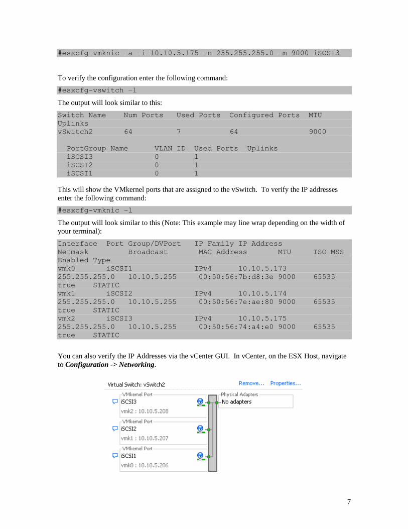
#esxcfg-vmknic –a –i 10.10.5.175 –n 255.255.255.0 –m 9000 iSCSI3
To verify the configuration enter the following command:
#esxcfg-vswitch –l
The output will look similar to this:
Switch Name Num Ports Used Ports Configured Ports MTU
Uplinks
vSwitch2 64 7 64 9000
PortGroup Name VLAN ID Used Ports Uplinks
iSCSI3 0 1
iSCSI2 0 1
iSCSI1 0 1
This will show the VMkernel ports that are assigned to the vSwitch. To verify the IP addresses
enter the following command:
#esxcfg-vmknic –l
The output will look similar to this (Note: This example may line wrap depending on the width of
your terminal):
Interface Port Group/DVPort IP Family IP Address
Netmask Broadcast MAC Address MTU TSO MSS
Enabled Type
vmk0 iSCSI1 IPv4 10.10.5.173
255.255.255.0 10.10.5.255 00:50:56:7b:d8:3e 9000 65535
true STATIC
vmk1 iSCSI2 IPv4 10.10.5.174
255.255.255.0 10.10.5.255 00:50:56:7e:ae:80 9000 65535
true STATIC
vmk2 iSCSI3 IPv4 10.10.5.175
255.255.255.0 10.10.5.255 00:50:56:74:a4:e0 9000 65535
true STATIC
You can also verify the IP Addresses via the vCenter GUI. In vCenter, on the ESX Host, navigate
to Configuration -> Networking.
8
Figure 4: vCenter GUI - VMkernel Ports
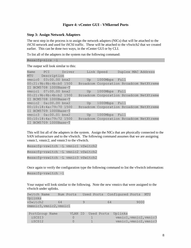
Step 3: Assign Network Adapters
The next step in the process is to assign the network adapters (NICs) that will be attached to the
iSCSI network and used for iSCSI traffic. These will be attached to the vSwitch2 that we created
earlier. This can be done two ways, in the vCenter GUI or by CLI.
To list all of the adapters in the system run the following command:
#esxcfg-nics –l
The output will look similar to this:
Name PCI Driver Link Speed Duplex MAC Address
MTU Description
vmnic0 03:00.00 bnx2 Up 1000Mbps Full
00:21:9b:8b:4b:b0 1500 Broadcom Corporation Broadcom NetXtreme
II BCM5708 1000Base-T
vmnic1 07:00.00 bnx2 Up 1000Mbps Full
00:21:9b:8b:4b:b2 1500 Broadcom Corporation Broadcom NetXtreme
II BCM5708 1000Base-T
vmnic2 0a:00.00 bnx2 Up 1000Mbps Full
00:10:18:4a:79:70 1500 Broadcom Corporation Broadcom NetXtreme
II BCM5709 1000Base-T
vmnic3 0a:00.01 bnx2 Up 1000Mbps Full
00:10:18:4a:79:72 1500 Broadcom Corporation Broadcom NetXtreme
II BCM5709 1000Base-T
This will list all of the adapters in the system. Assign the NICs that are physically connected to the
SAN infrastructure and to the vSwitch. The following command assumes that we are assigning
vmnic1, vmnic2, and vmnic3 to the vSwitch.
#esxcfg-vswitch –L vmnic1 vSwitch2
#esxcfg-vswitch –L vmnic2 vSwitch2
#esxcfg-vswitch –L vmnic3 vSwitch2
Once again to verify the configuration type the following command to list the vSwitch information:
#esxcfg-vswitch –l
Your output will look similar to the following. Note the new vmnics that were assigned to the
vSwitch under uplinks.
Switch Name Num Ports Used Ports Configured Ports MTU
Uplinks
vSwitch2 64 9 64 9000
vmmnic3,vmnic2,vmnic1
PortGroup Name VLAN ID Used Ports Uplinks iSCSI3 0 1 vmnic1,vmnic2,vmnic3
iSCSI2 0 1 vmnic1,vmnic2,vmnic3
9
iSCSI1 0 1 vmnic1,vmnic2,vmnic3
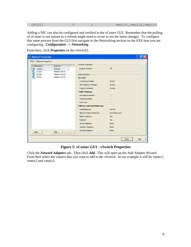
Adding a NIC can also be configured and verified in the vCenter GUI. Remember that the polling
of vCenter is not instant so a refresh might need to occur to see the latest changes. To configure
this same process from the GUI first navigate to the Networking section on the ESX host you are
configuring. Configuration -> Networking.
From here, click Properties on the vSwitch2.
Figure 5: vCenter GUI - vSwitch Properties
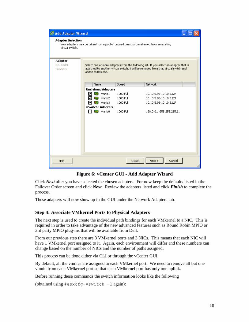
Click the Network Adapters tab. Then click Add. This will open up the Add Adapter Wizard.
From here select the vmnics that you want to add to the vSwitch. In our example it will be vmnic1,
vmnic2 and vmnic3.
10
Figure 6: vCenter GUI - Add Adapter Wizard
Click Next after you have selected the chosen adapters. For now keep the defaults listed in the
Failover Order screen and click Next. Review the adapters listed and click Finish to complete the
process.
These adapters will now show up in the GUI under the Network Adapters tab.
Step 4: Associate VMkernel Ports to Physical Adapters
The next step is used to create the individual path bindings for each VMkernel to a NIC. This is
required in order to take advantage of the new advanced features such as Round Robin MPIO or
3rd party MPIO plug-ins that will be available from Dell.
From our previous step there are 3 VMkernel ports and 3 NICs. This means that each NIC will
have 1 VMkernel port assigned to it. Again, each environment will differ and these numbers can
change based on the number of NICs and the number of paths assigned.
This process can be done either via CLI or through the vCenter GUI.
By default, all the vmnics are assigned to each VMkernel port. We need to remove all but one
vmnic from each VMkernel port so that each VMkernel port has only one uplink.
Before running these commands the switch information looks like the following
(obtained using #esxcfg-vswitch –l again):
11
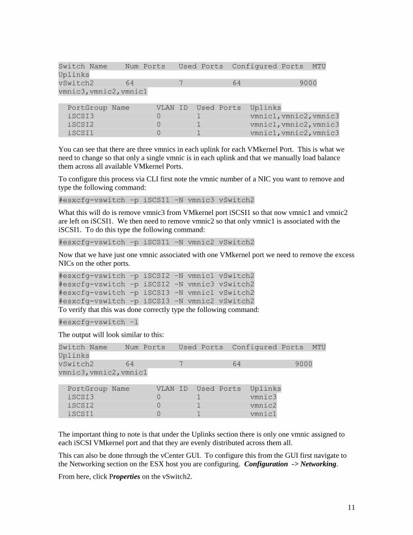
Switch Name Num Ports Used Ports Configured Ports MTU
Uplinks
vSwitch2 64 7 64 9000
vmnic3,vmnic2,vmnic1
PortGroup Name VLAN ID Used Ports Uplinks
iSCSI3 0 1 vmnic1,vmnic2,vmnic3
iSCSI2 0 1 vmnic1,vmnic2,vmnic3
iSCSI1 0 1 vmnic1,vmnic2,vmnic3
You can see that there are three vmnics in each uplink for each VMkernel Port. This is what we
need to change so that only a single vmnic is in each uplink and that we manually load balance
them across all available VMkernel Ports.
To configure this process via CLI first note the vmnic number of a NIC you want to remove and
type the following command:
#esxcfg-vswitch –p iSCSI1 –N vmnic3 vSwitch2
What this will do is remove vmnic3 from VMkernel port iSCSI1 so that now vmnic1 and vmnic2
are left on iSCSI1. We then need to remove vmnic2 so that only vmnic1 is associated with the
iSCSI1. To do this type the following command:
#esxcfg-vswitch –p iSCSI1 –N vmnic2 vSwitch2
Now that we have just one vmnic associated with one VMkernel port we need to remove the excess
NICs on the other ports.
#esxcfg-vswitch –p iSCSI2 –N vmnic1 vSwitch2
#esxcfg-vswitch –p iSCSI2 –N vmnic3 vSwitch2
#esxcfg-vswitch –p iSCSI3 –N vmnic1 vSwitch2
#esxcfg-vswitch –p iSCSI3 –N vmnic2 vSwitch2
To verify that this was done correctly type the following command:
#esxcfg-vswitch –l
The output will look similar to this:
Switch Name Num Ports Used Ports Configured Ports MTU
Uplinks
vSwitch2 64 7 64 9000
vmnic3,vmnic2,vmnic1
PortGroup Name VLAN ID Used Ports Uplinks
iSCSI3 0 1 vmnic3
iSCSI2 0 1 vmnic2
iSCSI1 0 1 vmnic1
The important thing to note is that under the Uplinks section there is only one vmnic assigned to
each iSCSI VMkernel port and that they are evenly distributed across them all.
This can also be done through the vCenter GUI. To configure this from the GUI first navigate to
the Networking section on the ESX host you are configuring. Configuration -> Networking.
From here, click Properties on the vSwitch2.
12
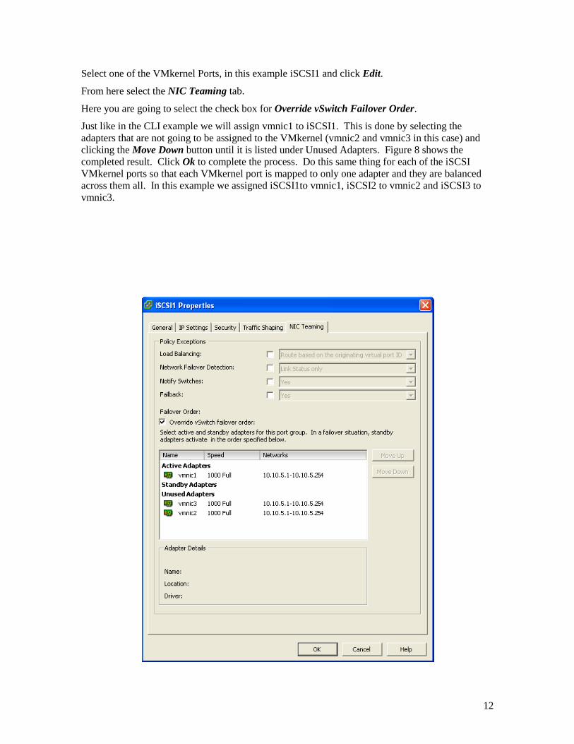
Select one of the VMkernel Ports, in this example iSCSI1 and click Edit.
From here select the NIC Teaming tab.
Here you are going to select the check box for Override vSwitch Failover Order.
Just like in the CLI example we will assign vmnic1 to iSCSI1. This is done by selecting the
adapters that are not going to be assigned to the VMkernel (vmnic2 and vmnic3 in this case) and
clicking the Move Down button until it is listed under Unused Adapters. Figure 8 shows the
completed result. Click Ok to complete the process. Do this same thing for each of the iSCSI
VMkernel ports so that each VMkernel port is mapped to only one adapter and they are balanced
across them all. In this example we assigned iSCSI1to vmnic1, iSCSI2 to vmnic2 and iSCSI3 to
vmnic3.
13
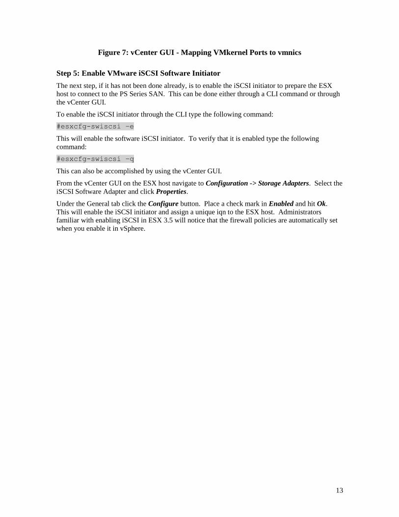
Figure 7: vCenter GUI - Mapping VMkernel Ports to vmnics
Step 5: Enable VMware iSCSI Software Initiator
The next step, if it has not been done already, is to enable the iSCSI initiator to prepare the ESX
host to connect to the PS Series SAN. This can be done either through a CLI command or through
the vCenter GUI.
To enable the iSCSI initiator through the CLI type the following command:
#esxcfg-swiscsi –e
This will enable the software iSCSI initiator. To verify that it is enabled type the following
command:
#esxcfg-swiscsi –q
This can also be accomplished by using the vCenter GUI.
From the vCenter GUI on the ESX host navigate to Configuration -> Storage Adapters. Select the
iSCSI Software Adapter and click Properties.
Under the General tab click the Configure button. Place a check mark in Enabled and hit Ok.
This will enable the iSCSI initiator and assign a unique iqn to the ESX host. Administrators
familiar with enabling iSCSI in ESX 3.5 will notice that the firewall policies are automatically set
when you enable it in vSphere.
14
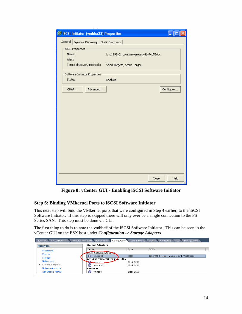
Figure 8: vCenter GUI - Enabling iSCSI Software Initiator
Step 6: Binding VMkernel Ports to iSCSI Software Initiator
This next step will bind the VMkernel ports that were configured in Step 4 earlier, to the iSCSI
Software Initiator. If this step is skipped there will only ever be a single connection to the PS
Series SAN. This step must be done via CLI.
The first thing to do is to note the vmhba# of the iSCSI Software Initiator. This can be seen in the
vCenter GUI on the ESX host under Configuration -> Storage Adapters.
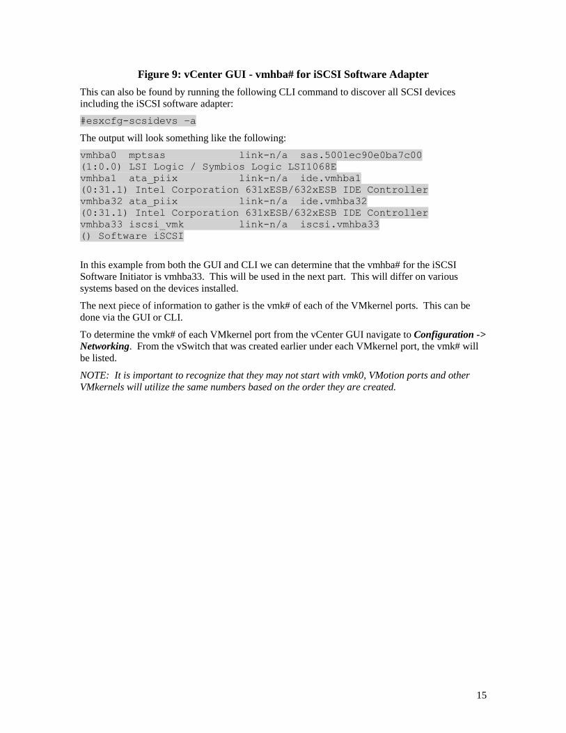
15
Figure 9: vCenter GUI - vmhba# for iSCSI Software Adapter
This can also be found by running the following CLI command to discover all SCSI devices
including the iSCSI software adapter:
#esxcfg-scsidevs –a
The output will look something like the following:
vmhba0 mptsas link-n/a sas.5001ec90e0ba7c00
(1:0.0) LSI Logic / Symbios Logic LSI1068E
vmhba1 ata_piix link-n/a ide.vmhba1
(0:31.1) Intel Corporation 631xESB/632xESB IDE Controller
vmhba32 ata_piix link-n/a ide.vmhba32
(0:31.1) Intel Corporation 631xESB/632xESB IDE Controller
vmhba33 iscsi_vmk link-n/a iscsi.vmhba33
() Software iSCSI
In this example from both the GUI and CLI we can determine that the vmhba# for the iSCSI
Software Initiator is vmhba33. This will be used in the next part. This will differ on various
systems based on the devices installed.
The next piece of information to gather is the vmk# of each of the VMkernel ports. This can be
done via the GUI or CLI.
To determine the vmk# of each VMkernel port from the vCenter GUI navigate to Configuration ->
Networking. From the vSwitch that was created earlier under each VMkernel port, the vmk# will
be listed.
NOTE: It is important to recognize that they may not start with vmk0, VMotion ports and other
VMkernels will utilize the same numbers based on the order they are created.
16
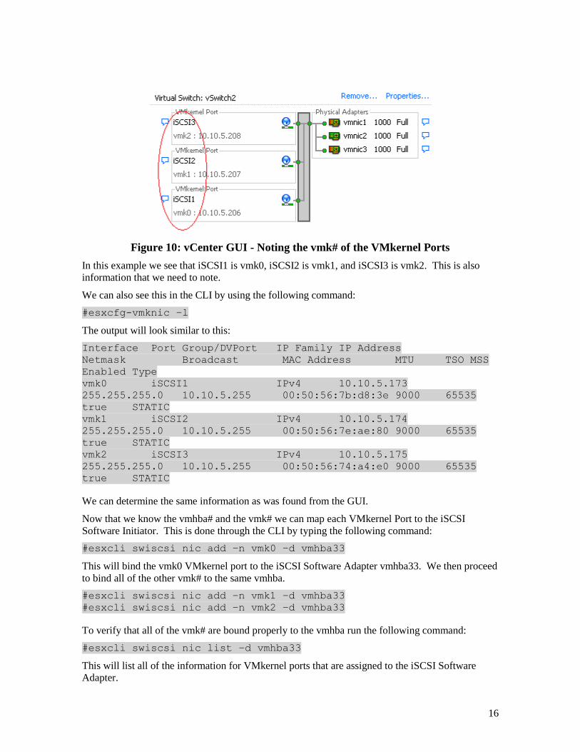
Figure 10: vCenter GUI - Noting the vmk# of the VMkernel Ports
In this example we see that iSCSI1 is vmk0, iSCSI2 is vmk1, and iSCSI3 is vmk2. This is also
information that we need to note.
We can also see this in the CLI by using the following command:
#esxcfg-vmknic –l
The output will look similar to this:
Interface Port Group/DVPort IP Family IP Address
Netmask Broadcast MAC Address MTU TSO MSS
Enabled Type
vmk0 iSCSI1 IPv4 10.10.5.173
255.255.255.0 10.10.5.255 00:50:56:7b:d8:3e 9000 65535
true STATIC
vmk1 iSCSI2 IPv4 10.10.5.174
255.255.255.0 10.10.5.255 00:50:56:7e:ae:80 9000 65535
true STATIC
vmk2 iSCSI3 IPv4 10.10.5.175
255.255.255.0 10.10.5.255 00:50:56:74:a4:e0 9000 65535
true STATIC
We can determine the same information as was found from the GUI.
Now that we know the vmhba# and the vmk# we can map each VMkernel Port to the iSCSI
Software Initiator. This is done through the CLI by typing the following command:
#esxcli swiscsi nic add –n vmk0 –d vmhba33
This will bind the vmk0 VMkernel port to the iSCSI Software Adapter vmhba33. We then proceed
to bind all of the other vmk# to the same vmhba.
#esxcli swiscsi nic add –n vmk1 –d vmhba33
#esxcli swiscsi nic add –n vmk2 –d vmhba33
To verify that all of the vmk# are bound properly to the vmhba run the following command:
#esxcli swiscsi nic list –d vmhba33
This will list all of the information for VMkernel ports that are assigned to the iSCSI Software
Adapter.
17
Step 7: Connect to the Dell EqualLogic PS Series Storage
Now that the advanced configuration for the vSphere iSCSI Software Initiator has been completed,
the next stage is to connect to the Dell EqualLogic PS Series SAN and to the volumes it contains.
More information for complete administration of the Dell PS Series SAN can be found in the PS
Series Administrators Guide. In this example we will attach the iSCSI Software Initiator to the
SAN and to a single volume. We will skip configuring CHAP but both one way and bi-directional
CHAP is supported by the PS Series SAN.
The first thing to do is add the PS Series Group IP Address to the dynamic discovery of the ESX
Host iSCSI Software Initiator. This is done to enable rescans to find new volumes that can be seen
by ESX and used to create Datastores.
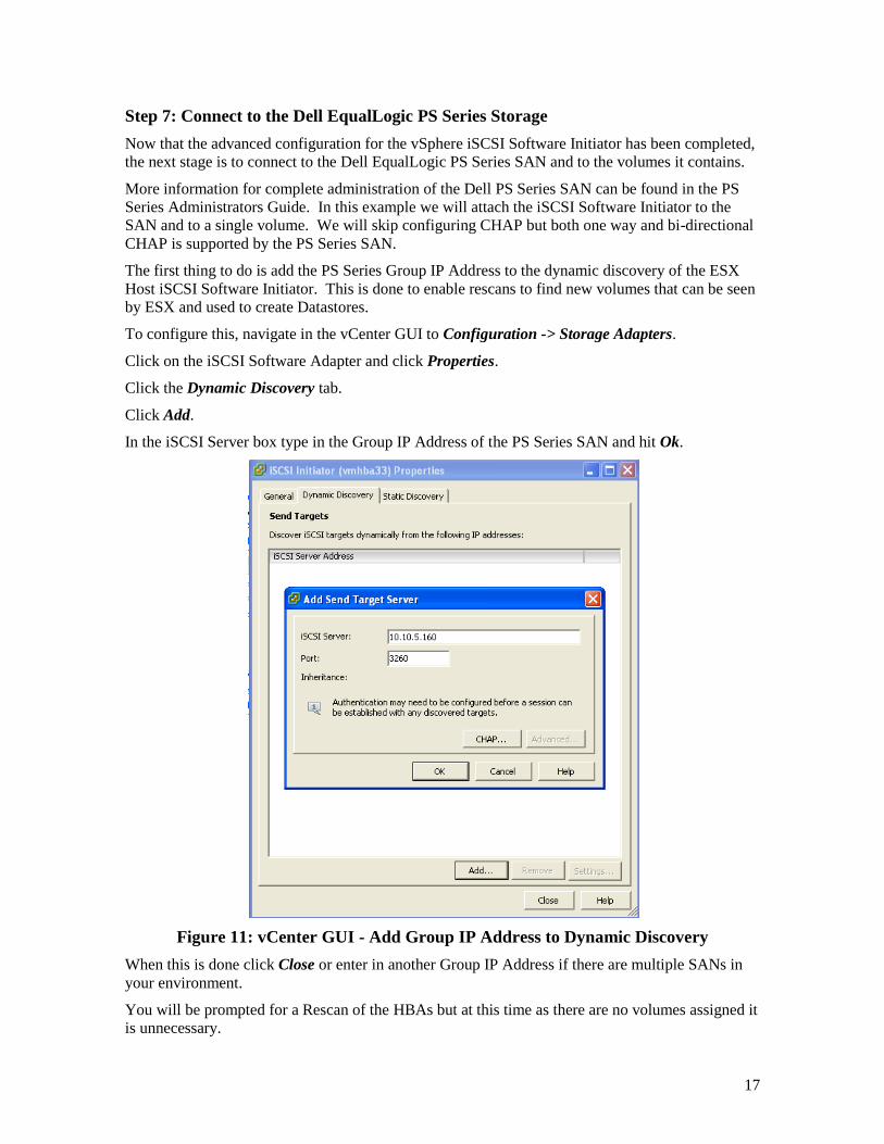
To configure this, navigate in the vCenter GUI to Configuration -> Storage Adapters.
Click on the iSCSI Software Adapter and click Properties.
Click the Dynamic Discovery tab.
Click Add.
In the iSCSI Server box type in the Group IP Address of the PS Series SAN and hit Ok.
Figure 11: vCenter GUI - Add Group IP Address to Dynamic Discovery
When this is done click Close or enter in another Group IP Address if there are multiple SANs in
your environment.
You will be prompted for a Rescan of the HBAs but at this time as there are no volumes assigned it
is unnecessary.
18
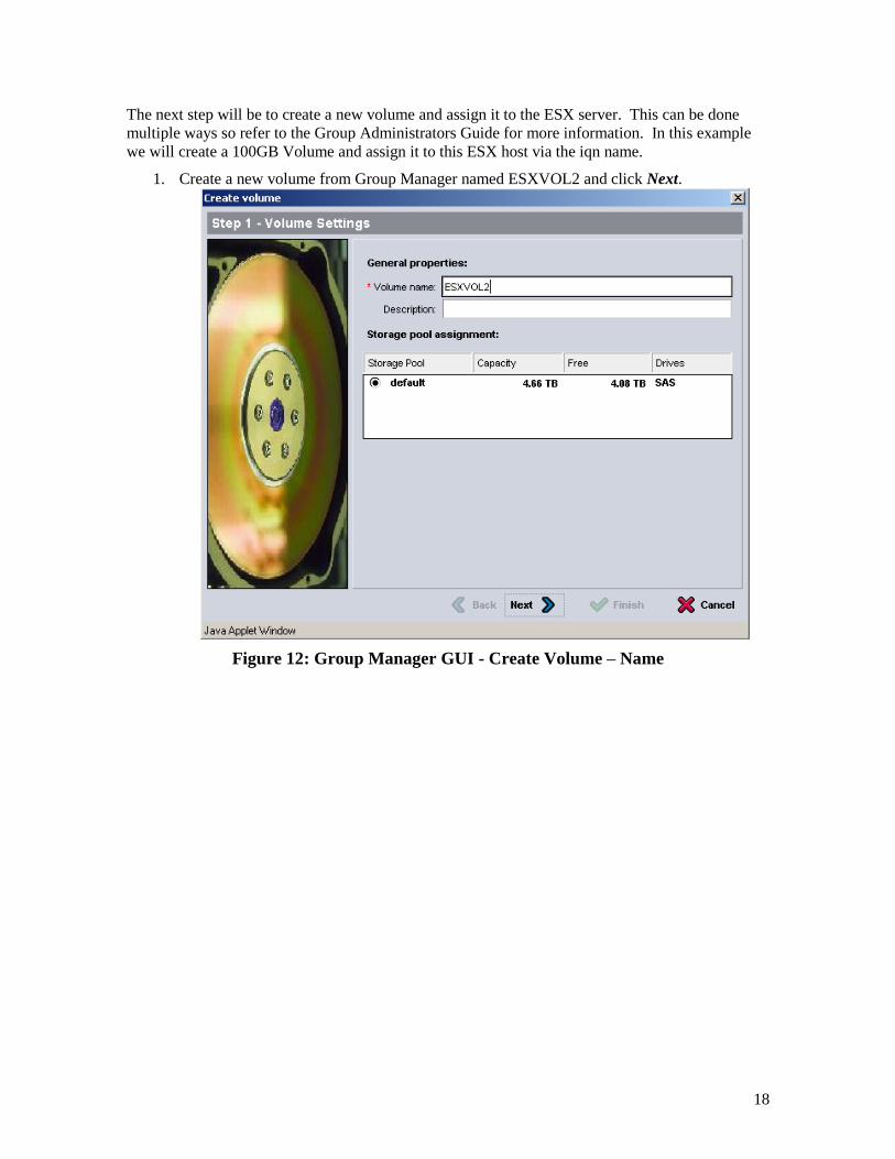
The next step will be to create a new volume and assign it to the ESX server. This can be done
multiple ways so refer to the Group Administrators Guide for more information. In this example
we will create a 100GB Volume and assign it to this ESX host via the iqn name.
1. Create a new volume from Group Manager named ESXVOL2 and click Next.
Figure 12: Group Manager GUI - Create Volume – Name
19
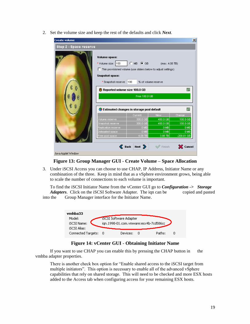
2. Set the volume size and keep the rest of the defaults and click Next.
Figure 13: Group Manager GUI - Create Volume – Space Allocation
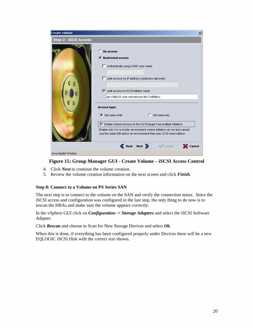
3. Under iSCSI Access you can choose to use CHAP, IP Address, Initiator Name or any
combination of the three. Keep in mind that as a vSphere environment grows, being able
to scale the number of connections to each volume is important.
To find the iSCSI Initiator Name from the vCenter GUI go to Configuration -> Storage
Adapters. Click on the iSCSI Software Adapter. The iqn can be copied and pasted
into the Group Manager interface for the Initiator Name.
Figure 14: vCenter GUI - Obtaining Initiator Name
If you want to use CHAP you can enable this by pressing the CHAP button in the
vmhba adapter properties.
There is another check box option for “Enable shared access to the iSCSI target from
multiple initiators”. This option is necessary to enable all of the advanced vSphere
capabilities that rely on shared storage. This will need to be checked and more ESX hosts
added to the Access tab when configuring access for your remaining ESX hosts.
20
Figure 15: Group Manager GUI - Create Volume – iSCSI Access Control
4. Click Next to continue the volume creation.
5. Review the volume creation information on the next screen and click Finish.
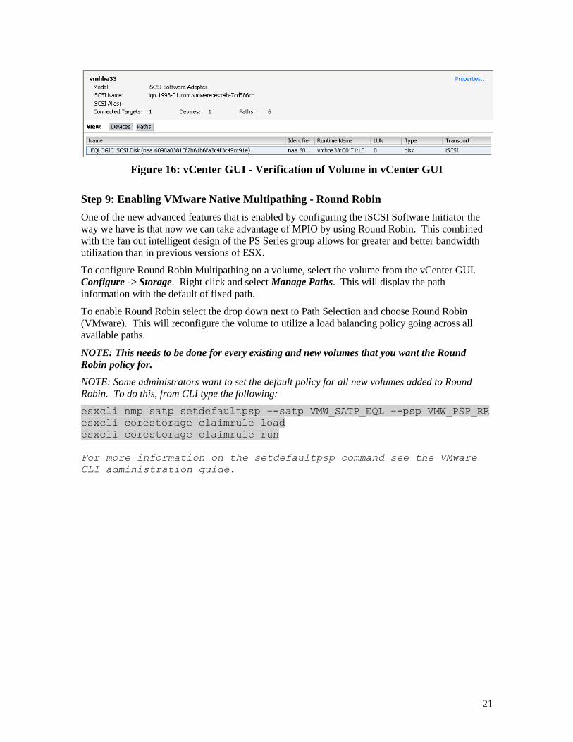
Step 8: Connect to a Volume on PS Series SAN
The next step is to connect to the volume on the SAN and verify the connection status. Since the
iSCSI access and configuration was configured in the last step, the only thing to do now is to
rescan the HBAs and make sure the volume appears correctly.
In the vSphere GUI click on Configuration -> Storage Adapters and select the iSCSI Software
Adapter.
Click Rescan and choose to Scan for New Storage Devices and select Ok.
When this is done, if everything has been configured properly under Devices there will be a new
EQLOGIC iSCSI Disk with the correct size shown.
21
Figure 16: vCenter GUI - Verification of Volume in vCenter GUI
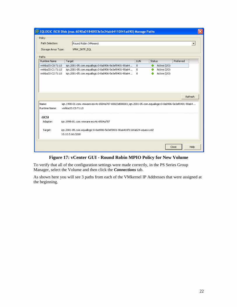
Step 9: Enabling VMware Native Multipathing - Round Robin
One of the new advanced features that is enabled by configuring the iSCSI Software Initiator the
way we have is that now we can take advantage of MPIO by using Round Robin. This combined
with the fan out intelligent design of the PS Series group allows for greater and better bandwidth
utilization than in previous versions of ESX.
To configure Round Robin Multipathing on a volume, select the volume from the vCenter GUI.
Configure -> Storage. Right click and select Manage Paths. This will display the path
information with the default of fixed path.
To enable Round Robin select the drop down next to Path Selection and choose Round Robin
(VMware). This will reconfigure the volume to utilize a load balancing policy going across all
available paths.
NOTE: This needs to be done for every existing and new volumes that you want the Round
Robin policy for.
NOTE: Some administrators want to set the default policy for all new volumes added to Round
Robin. To do this, from CLI type the following:
esxcli nmp satp setdefaultpsp –-satp VMW_SATP_EQL –-psp VMW_PSP_RR
esxcli corestorage claimrule load
esxcli corestorage claimrule run
For more information on the setdefaultpsp command see the VMware
CLI administration guide.
22
Figure 17: vCenter GUI - Round Robin MPIO Policy for New Volume
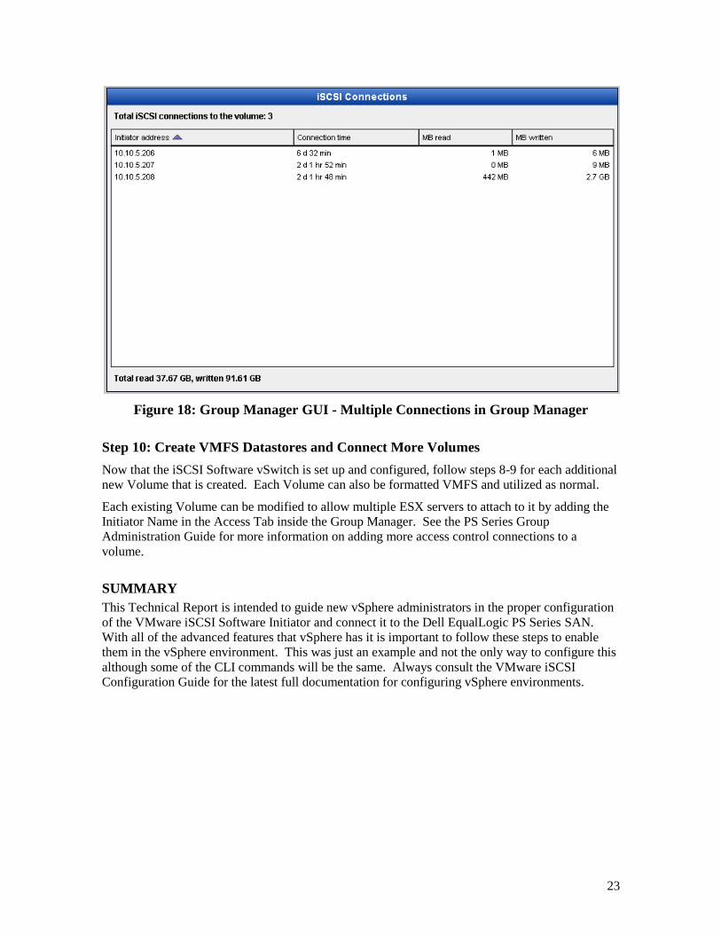
To verify that all of the configuration settings were made correctly, in the PS Series Group
Manager, select the Volume and then click the Connections tab.
As shown here you will see 3 paths from each of the VMkernel IP Addresses that were assigned at
the beginning.
23
Figure 18: Group Manager GUI - Multiple Connections in Group Manager
Step 10: Create VMFS Datastores and Connect More Volumes
Now that the iSCSI Software vSwitch is set up and configured, follow steps 8-9 for each additional
new Volume that is created. Each Volume can also be formatted VMFS and utilized as normal.
Each existing Volume can be modified to allow multiple ESX servers to attach to it by adding the
Initiator Name in the Access Tab inside the Group Manager. See the PS Series Group
Administration Guide for more information on adding more access control connections to a
volume.
SUMMARY
This Technical Report is intended to guide new vSphere administrators in the proper configuration
of the VMware iSCSI Software Initiator and connect it to the Dell EqualLogic PS Series SAN.
With all of the advanced features that vSphere has it is important to follow these steps to enable
them in the vSphere environment. This was just an example and not the only way to configure this
although some of the CLI commands will be the same. Always consult the VMware iSCSI
Configuration Guide for the latest full documentation for configuring vSphere environments.
24
TECHNICAL SUPPORT AND CUSTOMER SERVICE
Dell's support service is available to answer your questions about PS Series SAN arrays. If you
have an Express Service Code, have it ready when you call. The code helps Dell's automated-
support telephone system direct your call more efficiently.
Contacting Dell
Dell provides several online and telephone-based support and service options. Availability varies
by country and product, and some services might not be available in your area.
For customers in the United States, call 800-945-3355.
Note: If you do not have access to an Internet connection, contact information is printed on your
invoice, packing slip, bill, or Dell product catalog.
Use the following procedure to contact Dell for sales, technical support, or customer service issues:
1. Visit support.dell.com or the Dell support URL specified in information provided with the Dell
product.
2. Select your locale. Use the locale menu or click on the link that specifies your country or
region.
3. Select the required service. Click the "Contact Us" link, or select the Dell support service from
the list of services provided.
4. Choose your preferred method of contacting Dell support, such as e-mail or telephone.
Online Services
You can learn about Dell products and services using the following procedure:
1. Visit www.dell.com (or the URL specified in any Dell product information).
2. Use the locale menu or click on the link that specifies your country or region

25
Appendix A – Configure MPIO for ESX4i
The steps for ESX and ESXi are basically identical. However, the way to perform the "esxcli"
commands is different, since ESXi does not have an internal service console. Instead, the
commands need to be run from a remote CLI perl script program which can be run from a physical
Windows server or a Windows virtual machine. VMware also provides the vSphere Management
Assistant (vMA) virtual appliance which you can use to run all of these commands. The
installation and configuration of the vMA is beyond the scope of this document.
To perform the necessary steps in ESXi, first download and install the Remote CLI package for
ESXi. Go to vmware.com, click Support & Downloads, VMware ESXi, Download ESXi. Click on
the Drivers and Tools tab and expand the Automation Tools and SDKs. Download and install
"VMware vSphere CLI 4.x".
Then for each command listed in the Tech Report, use the analogous command from the Remote
CLI package. When you start the Remote CLI, it puts you in the CLI directory. You can see the
commands available by looking in the "bin" directory. You will need to specify the server IP
address to communicate with.
For instance, for the command " #esxcfg-nics -l", your remote CLI command would be changed to
this (where 192.168.1.28 is the IP address of your ESXi server):
bin\esxcfg-nics.pl -l --server 192.168.1.28
Name PCI Driver Link Speed Duplex MAC Address MTU
Description
vmnic0 03:00.00 bnx2 Up 1000Mbps Full 00:21:9b:8b:4b:b0 1500
Broadcom Corporation Broadcom NetXtreme II BCM5708 1000Base-T
vmnic1 07:00.00 bnx2 Up 1000Mbps Full 00:21:9b:8b:4b:b2 1500
Broadcom Corporation Broadcom NetXtreme II BCM5708 1000Base-T
vmnic2 0a:00.00 bnx2 Up 1000Mbps Full 00:10:18:4a:79:70 1500
Broadcom Corporation Broadcom NetXtreme II BCM5709 1000Base-T
vmnic3 0a:00.01 bnx2 Up 1000Mbps Full 00:10:18:4a:79:72 1500
Broadcom Corporation Broadcom NetXtreme II BCM5709 1000Base-T
Note: Most of the commands are Perl files (command-name.pl), but "esxcli" by itself is a .EXE. So
the command "#esxcli swiscsi nic add –n vmk0 –d vmhba33" becomes:
bin\esxcli --server 192.168.1.28 swiscsi nic add –n vmk0 –d vmhba33
A full description of all the Remote CLI commands and how to use them, including how to set up a
default ESX server and/or login credentials, is beyond the scope of this document. Check with
VMware for more guidance about these commands.
26
Appendix B – Scalability and Scripting
VMware vSphere 4.0 introduced a number of advanced integration techniques to help
administrators quickly scale out their environment. One of these new tools is called Host Profiling.
The idea behind Host Profiles is to make a single ESX 4.X server a “gold master” and any new
ESX servers that join the Datacenter can inherit all of the configuration settings of the gold master.
As of the writing of this Technical Report, Host Profiles did not propagate all of the correct
vSwitch settings that this article describes. By using Host Profiles it will create the vSwitch and
the VMkernel ports but Jumbo Frames are not enabled by default and the uplinks still have to be
configured.
Because of this, it is recommended that instead of using Host Profiles, administrators can take
advantage of simple shell scripting commands to automate the instructions detailed here. With 4.1
Administrators can take advantage of the automated setup script provided by Dell in the
Multipathing Extension Module.
Below is a shell script that will automatically create the entire environment detailed in the example
of this Technical Report. There are some assumptions that the information is the same from ESX
host to ESX host and that there is no error checking in such a simple script but it can be used to
help automate new ESX servers being added to the environment. Even more advanced scripting
can be utilized to the effect of actually inputting values during run time but that is beyond the scope
of this appendix.
This script can be created on a standalone server and the values inputted before being moved to the
ESX server in question.
To create a new shell script in ESX run:
vi MPIO_Config.sh
This will create a new shell script file that can be modified to automate the entire process. Or this
can be created on another system and moved to the ESX server.
Once it is created or moved, proper permissions need to be assigned so that it can be run. To do
this, navigate to the directory where you uploaded the file and type in the following commands:
chmod 777 MPIO_Config.sh
This will change the permissions on the file to allow anyone to run it. For more information on the
chmod command, its usage, and implications see the man pages on the command.
To run the shell script, navigate to the directory in which you uploaded it and run:
./MPIO_Config.sh
27
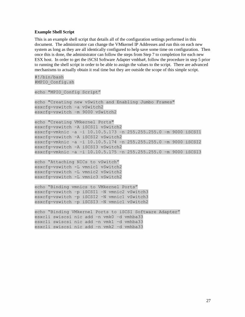
Example Shell Script
This is an example shell script that details all of the configuration settings performed in this
document. The administrator can change the VMkernel IP Addresses and run this on each new
system as long as they are all identically configured to help save some time on configuration. Then
once this is done, the administrator can follow the steps from Step 7 to completion for each new
ESX host. In order to get the iSCSI Software Adapter vmhba#, follow the procedure in step 5 prior
to running the shell script in order to be able to assign the values to the script. There are advanced
mechanisms to actually obtain it real time but they are outside the scope of this simple script.
#!/bin/bash
#MPIO_Config.sh
echo "MPIO_Config Script”
echo "Creating new vSwitch and Enabling Jumbo Frames"
esxcfg-vswitch –a vSwitch2
esxcfg-vswitch –m 9000 vSwitch2
echo "Creating VMkernel Ports"
esxcfg-vswitch –A iSCSI1 vSwitch2
esxcfg-vmknic –a –i 10.10.5.173 –n 255.255.255.0 –m 9000 iSCSI1
esxcfg-vswitch –A iSCSI2 vSwitch2
esxcfg-vmknic –a –i 10.10.5.174 –n 255.255.255.0 –m 9000 iSCSI2
esxcfg-vswitch –A iSCSI3 vSwitch2
esxcfg-vmknic –a –i 10.10.5.175 –n 255.255.255.0 –m 9000 iSCSI3
echo “Attaching NICs to vSwitch”
esxcfg-vswitch -L vmnic1 vSwitch2
esxcfg-vswitch -L vmnic2 vSwitch2
esxcfg-vswitch -L vmnic3 vSwitch2
echo “Binding vmnics to VMkernel Ports”
esxcfg-vswitch –p iSCSI1 –N vmnic2 vSwitch3
esxcfg-vswitch –p iSCSI2 –N vmnic1 vSwitch3
esxcfg-vswitch –p iSCSI3 –N vmnic1 vSwitch2
echo “Binding VMkernel Ports to iSCSI Software Adapter”
esxcli swiscsi nic add –n vmk0 –d vmhba33
esxcli swiscsi nic add –n vmk1 –d vmhba33
esxcli swiscsi nic add –n vmk2 –d vmhba33
28
Appendix C - Removing Extra VMkernel Ports In previous editions of this document it was possible to assign multiple VMkernel ports to physical
nics. This was called over subscribing and was done to attempt to obtain more bandwidth for the
environment especially when the ESX server had 10Gb nics and the SAN was running multiple
1Gb ports. Dell and VMware have changed the support for this practice and now only recommend
using a 1:1 VMkernel binding process as described in this updated technical report. If you are
running an environment that has VMkernel oversubscriptions it is advised that you follow the
below steps and configure the server as recommended.
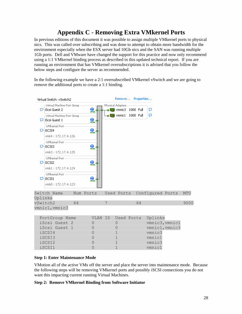
In the following example we have a 2:1 oversubscribed VMkernel vSwitch and we are going to
remove the additional ports to create a 1:1 binding.
Switch Name Num Ports Used Ports Configured Ports MTU
Uplinks
vSwitch2 64 7 64 9000
vmnic1,vmnic3
PortGroup Name VLAN ID Used Ports Uplinks
iScsi Guest 2 0 0 vmnic3,vmnic1
iScsi Guest 1 0 0 vmnic1,vmnic3
iSCSI4 0 1 vmnic3
iSCSI3 0 1 vmnic1
iSCSI2 0 1 vmnic3
iSCSI1 0 1 vmnic1
Step 1: Enter Maintenance Mode
VMotion all of the active VMs off the server and place the server into maintenance mode. Because
the following steps will be removing VMkernel ports and possibly iSCSI connections you do not
want this impacting current running Virtual Machines.
Step 2: Remove VMkernel Binding from Software Initiator
29
The first thing to do is to remove the VMkernel Binding from the software initiator adapter. This is
done so that later VMkernels are not automatically assigned to the software adapter by accident.
Since we are moving to a 1:1 VMkernel binding, remove all VMkernels in excess of this. In this
example you can see vmk3 and vmk4 are in excess of the 1:1 binding. To see which VMkernels
we have bound to the software adapter use the following command:
esxcli swiscsi nic list -d vmhba33
To remove excess vmk ports type the following:
esxcli swiscsi nic remove -n vmk3 -d vmhba33
esxcli swiscsi nic remove -n vmk4 -d vmhba33
This removes vmk3 and vmk4 from the vmhba it is assigned to since in this example these are the
two oversubscribed ports we want to remove. Re-verify that they are now gone.
Step 3: Remove Excess VMkernels
Now that the VMkernel ports have been removed from the software adapter, we want to remove
them from the vSwitch. This can be done either through the GUI by selecting the vSwitch and
clicking Properties. Select the VMkernel Port you want to remove and click Remove. Do this for
all extra VMkernel ports.
Step 4: Rebalance VMkernel port to Physical nic relationship
Once the excess VMkernel ports are removed, you need to double check that each of the remaining
VMkernel ports are correctly bound to a unique physical nic. This can be done through the GUI or
via CLI using the instructions in Part 4 of this technical document. Verify that each VMkernel is
now only bound 1:1 to a physical nic.
Step 5: Reboot and Verify
After these steps have been done, reboot the server, verify that all the configuration changes you
made have been applied, verify the correct path connectivity and exit the host from maintenance
mode. Do this for all servers until they have the recommended 1:1 binding.