Embed Size (px)
Citation preview

Chapter 9
vSphere Distributed Switch
Key Concepts ■ dvUplinks
■ LLDP
■ NetFlow
■ Port Mirroring
■ Private VLANs
■ Egress Shaping
■ Load-based Teaming
■ Network I/O Control
Introduction to the vSphere Distributed SwitchThe vSphere Distributed Switch (VDS) provides two major benefits to you, the customer. First, the VDS offers a centralized control plane for management of your virtual switching, taking much of the manual grunt work out of day-to-day administration. Second, the VDS offers advanced services and features over the standard switch.
09_9780133511086_ch09.indd 9309_9780133511086_ch09.indd 93 2/25/14 8:42 PM2/25/14 8:42 PM

94 CHAPTER 9 vSphere Distributed Switch
The VDS sits in the middle of the feature scale, offering more capabilities than the stan-dard switch, but leaving some room at the table for third-party switches such as the Cisco Nexus 1000V. We go further into third-party vSwitches in the next chapter. For now, we focus more on the VDS, how it is different from the standard switch, and some of the neat buttons and gizmos that it comes loaded with.
Control PlaneThe control plane of the VDS sits at the vCenter layer of the stack. That is, vCenter is the vehicle used to create, modify, and remove a VDS and its related virtual port groups. This means that you can create your VDS one time and then choose which hosts will use it. It’s a similar concept to the vSphere cluster. On its own, a cluster doesn’t really do anything. You can set up the cluster’s High Availability (HA) and Distributed Resource Scheduler (DRS) options, but until you actually add some hosts to the cluster, it just sits there looking pretty. A VDS is useless until hosts are added to it, and only then does the magic happen.
Each VDS has a quantity of uplinks defined. These are named dvUplinks with a number after them by default, but you can change the name. From a control plane perspective, giv-ing your uplinks a custom name helps define the role of various uplinks each host will use to move traffic into and out of the VDS. When adding a host to the VDS, you map physi-cal uplink ports to the logical dvUplink ports. Figure 9.1 shows the dvUplinks in a VDS using a custom name of “Core 1” and “Core 2” for the pair of dvUplinks.
TIP
Name your uplinks something descriptive to help with troubleshooting. I like to label mine based on the VDS’s purpose, such as “Core-##” or “Storage-##.” You could also call out the physical switching infrastructure, such as “TOR-A” or “TOR-B,” to distinguish which top of rack (TOR) switch you are connecting to. Avoid using specific switch names or IPs, as that information is tracked by CDP or LLDP anyway. More on LLDP in a later section.
Handling vCenter FailureThat VDSes are managed through vCenter might be causing you some heartburn, as it seems to imply a dependency on vCenter availability. You might be wondering what hap-pens when vCenter goes down—will virtual switching just stop?
09_9780133511086_ch09.indd 9409_9780133511086_ch09.indd 94 2/25/14 8:42 PM2/25/14 8:42 PM
95Introduction to the vSphere Distributed Switch
Figure 9.1 The dvUplinks in a VDS
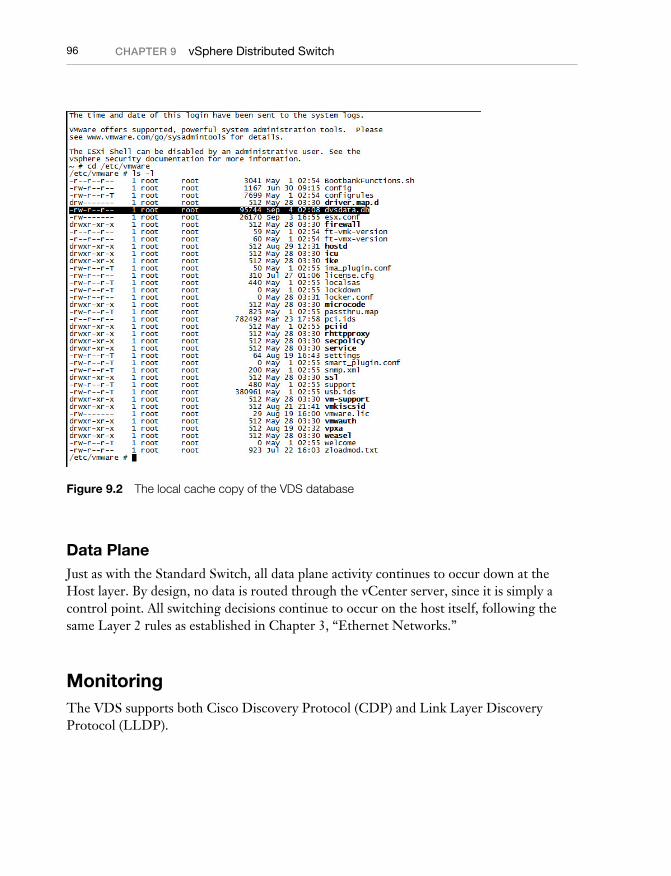
The short answer is no, switching will continue without interruption. But, hey, we have a couple hundred pages to go, so let’s get into the long answer. While it’s true that the brains of a VDS lay with the vCenter server, there is a cached copy of the VDS con-figuration kept on every vSphere host and updated every five minutes. If vCenter fails, the host continues to use this cached copy of the VDS configuration. You can log into your vSphere host via Secure Shell (SSH) and see the file if you browse to /etc/vmware/dvsdata.db. The cached database is shown in Figure 9.2.
When the vCenter server comes back online, you might see a few errors appear stating that the VDS configuration is not synchronized to some of your hosts. This will clear up shortly as the vCenter VDS configuration is pushed down to the vSphere host during the regular five-minute update interval.
09_9780133511086_ch09.indd 9509_9780133511086_ch09.indd 95 2/25/14 8:42 PM2/25/14 8:42 PM
96 CHAPTER 9 vSphere Distributed Switch
Figure 9.2 The local cache copy of the VDS database
Data PlaneJust as with the Standard Switch, all data plane activity continues to occur down at the Host layer. By design, no data is routed through the vCenter server, since it is simply a control point. All switching decisions continue to occur on the host itself, following the same Layer 2 rules as established in Chapter 3, “Ethernet Networks.”
MonitoringThe VDS supports both Cisco Discovery Protocol (CDP) and Link Layer Discovery Protocol (LLDP).
09_9780133511086_ch09.indd 9609_9780133511086_ch09.indd 96 2/25/14 8:42 PM2/25/14 8:42 PM
97Monitoring
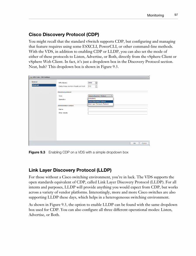
Cisco Discovery Protocol (CDP)You might recall that the standard vSwitch supports CDP, but configuring and managing that feature requires using some ESXCLI, PowerCLI, or other command-line methods. With the VDS, in addition to enabling CDP or LLDP, you can also set the mode of either of these protocols to Listen, Advertise, or Both, directly from the vSphere Client or vSphere Web Client. In fact, it’s just a dropdown box in the Discovery Protocol section. Neat, huh? This dropdown box is shown in Figure 9.3.
Figure 9.3 Enabling CDP on a VDS with a simple dropdown box
Link Layer Discovery Protocol (LLDP)For those without a Cisco switching environment, you’re in luck. The VDS supports the open standards equivalent of CDP, called Link Layer Discovery Protocol (LLDP). For all intents and purposes, LLDP will provide anything you would expect from CDP, but works across a variety of vendor platforms. Interestingly, more and more Cisco switches are also supporting LLDP these days, which helps in a heterogeneous switching environment.
As shown in Figure 9.3, the option to enable LLDP can be found with the same dropdown box used for CDP. You can also configure all three different operational modes: Listen, Advertise, or Both.
09_9780133511086_ch09.indd 9709_9780133511086_ch09.indd 97 2/25/14 8:42 PM2/25/14 8:42 PM

98 CHAPTER 9 vSphere Distributed Switch
TIP
One question that commonly pops up revolves around the desire to set LLDP (or even CDP for that matter) into an Advertise or Both mode and what the down side might be. We have yet to encounter any environments where having additional information about the environment—from a perspective of server or networking—is a bad thing. While some organizations will have a policy preventing LLDP or CDP from being enabled in specific, compliance-related environments, most are okay with having it on. Check with your security and/or networking team first, but chances are high that they will appreciate having visibility into the virtual networking environment.
NetFlowNow we’re starting to hit some of the value-add features that people really enjoy about the VDS. The first one is NetFlow, and it’s an advanced feature available to you on the VDS. NetFlow doesn’t really have anything to do specifically with VMware, but was originally developed by Cisco and has become a reasonably standard mechanism to perform network analysis.
In Chapter 7, “How Virtual Switching Differs from Physical Switching,” we mentioned the idea of dark traffic: traffic that might never end up leaving a host. This is because both the source and destination VMs are located on the same host. Perhaps two VMs are talk-ing to one another on the same VLAN and happen to be on the same host. Heck, that’s sometimes done on purpose to avoid putting additional stress on the physical network and because dark traffic gets switched at a host’s much faster processor/RAM speeds rather than at physical networking speeds. NetFlow is a way to monitor and sample IP traffic that occurs within your VDS. The configuration is controllable down to the port group level. The traffic data is sent to a NetFlow collector running elsewhere on the network. NetFlow is commonly used in the physical world to help gain visibility into traffic and understand-ing just who is sending what and to where.
NetFlow comes in a variety of versions, from v1 to v10. VMware uses the IPFIX version of NetFlow, which is version 10, and stands for “Internet Protocol Flow Information eXport.” IPFIX is actually a melding of NetFlow version 9 with some Internet Engineer-ing Task Force (IETF) standards, and is sometimes referred to as the “IETF Standardized NetFlow 9.” If you find it confusing that version 10 is sometimes called IPFIX 9, you’re not alone. To keep things simple, it’s often best to just call it IPFIX and folks will know what you mean.
09_9780133511086_ch09.indd 9809_9780133511086_ch09.indd 98 2/25/14 8:42 PM2/25/14 8:42 PM
99Monitoring
TIP
vSphere 5.0 uses NetFlow version 5, while vSphere 5.1 and beyond uses IPFIX (version 10). If you are using software that requires version 5, or doesn’t support IPFIX, you might want to avoid upgrading your vSphere hosts until you can figure out a workaround. vSphere 5.1 does not support NetFlow version 5.
In order to take advantage of NetFlow, you need to perform two steps. The first is to con-figure the NetFlow settings on your VDS itself, which we go into deeper here.
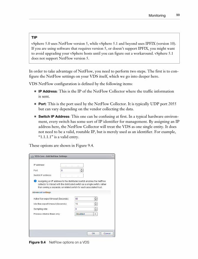
VDS NetFlow configuration is defined by the following items:
■ IP Address: This is the IP of the NetFlow Collector where the traffic information is sent.
■ Port: This is the port used by the NetFlow Collector. It is typically UDP port 2055 but can vary depending on the vendor collecting the data.
■ Switch IP Address: This one can be confusing at first. In a typical hardware environ-ment, every switch has some sort of IP identifier for management. By assigning an IP address here, the NetFlow Collector will treat the VDS as one single entity. It does not need to be a valid, routable IP, but is merely used as an identifier. For example, “1.1.1.1” is a valid entry.
These options are shown in Figure 9.4.
Figure 9.4 NetFlow options on a VDS
09_9780133511086_ch09.indd 9909_9780133511086_ch09.indd 99 2/25/14 8:42 PM2/25/14 8:42 PM
100 CHAPTER 9 vSphere Distributed Switch
There are also a number of advanced settings that can be tweaked if desired:
■ Active flow export timeout in seconds: The amount of time that must pass before the switch fragments the flow and ships it off to the collector. This avoids sending a large quantity of data after a particularly long flow occurs.
■ Idle flow export timeout in seconds: Similar to the active flow timeout, but for flows that have entered an idle state. Think of this as the cleanup necessary to ensure that an idle flow gets shipped off to the collector in a timely fashion.
■ Sampling rate: This determines the Nth packet to collect. By default, the value is 0, meaning to collect all packets. If you set the value to something other than 0, it will collect every Nth packet. For example, 3 would only collect every third packet.
■ Process internal flows only: Your choices here are enabled or disabled (default). Enabling ensures that the only flows collected are ones that occur between VMs on the same host. This can be helpful if you are only looking to collect the dark traffic flows, already have NetFlow configured on your physical infrastructure, and wish to avoid sampling traffic twice (once at the Virtual layer and again at the Physical layer).
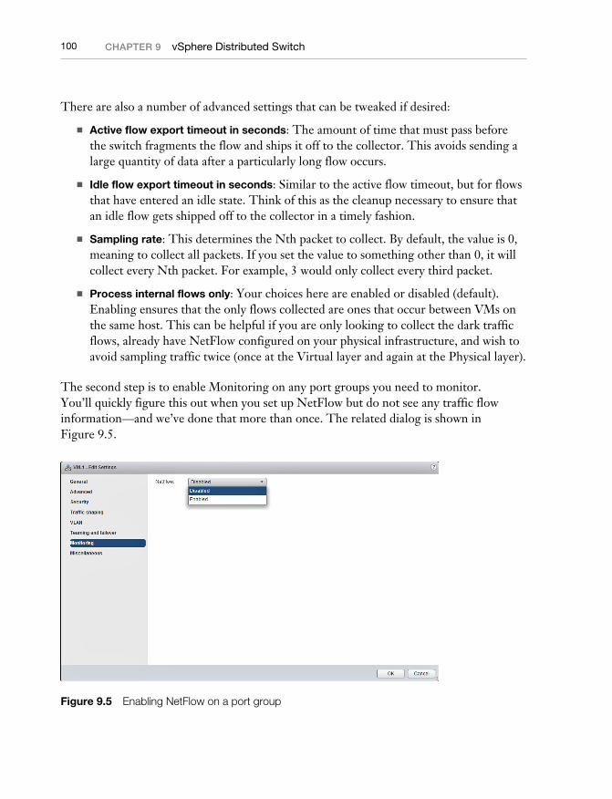
The second step is to enable Monitoring on any port groups you need to monitor. You’ll quickly figure this out when you set up NetFlow but do not see any traffic flow information—and we’ve done that more than once. The related dialog is shown in Figure 9.5.
Figure 9.5 Enabling NetFlow on a port group
09_9780133511086_ch09.indd 10009_9780133511086_ch09.indd 100 2/25/14 8:42 PM2/25/14 8:42 PM
101Monitoring
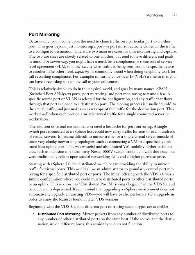
Port MirroringOccasionally, you’ll come upon the need to clone traffic on a particular port to another port. This goes beyond just monitoring a port—a port mirror actually clones all the traffic to a configured destination. There are two main use cases for this: monitoring and capture. The two use cases are closely related to one another, but tend to have different end goals in mind. For monitoring, you might have a need, be it compliance or some sort of service level agreement (SLA), to know exactly what traffic is being sent from one specific device to another. The other need, capturing, is commonly found when doing telephony work for call recording compliance. For example: capturing voice-over IP (VoIP) traffic so that you can have a recording of a phone call in your call center.
This is relatively simple to do in the physical world, and goes by many names: SPAN (Switched Port ANalyzer) ports, port mirroring, and port monitoring to name a few. A specific source port or VLAN is selected for the configuration, and any traffic that flows through that port is cloned to a destination port. The cloning process is usually “dumb” to the actual traffic, and just makes an exact copy of the traffic for the destination port. This worked well when each port on a switch carried traffic for a single connected server or workstation.
The addition of virtual environments created a headache for port mirroring. A single switch port connected to a vSphere host could now carry traffic for tens or even hundreds of virtual servers. It became difficult to mirror traffic for a single virtual server outside of some very clunky networking topologies, such as connecting a VM to a specifically dedi-cated host uplink port. This was wasteful and also limited VM mobility. Other technolo-gies, such as inclusion of a third party Nexus 1000V switch, could help with this issue, but were traditionally reliant upon special networking skills and a higher purchase price.
Starting with vSphere 5.0, the distributed switch began providing the ability to mirror traffic for virtual ports. This would allow an administrator to granularly control port mir-roring for a specific distributed port or ports. The initial offering with the VDS 5.0 was a simple configuration where you could mirror distributed ports to other distributed ports or an uplink. This is known as “Distributed Port Mirroring (Legacy)” in the VDS 5.1 and beyond, and is deprecated. Keep in mind that upgrading a vSphere environment does not automatically upgrade an existing VDS—you will have to also perform a VDS upgrade in order to enjoy the features found in later VDS versions.
Beginning with the VDS 5.1, four different port mirroring session types are available:
1. Distributed Port Mirroring: Mirror packets from any number of distributed ports to any number of other distributed ports on the same host. If the source and the desti-nation are on different hosts, this session type does not function.
09_9780133511086_ch09.indd 10109_9780133511086_ch09.indd 101 2/25/14 8:42 PM2/25/14 8:42 PM
102 CHAPTER 9 vSphere Distributed Switch
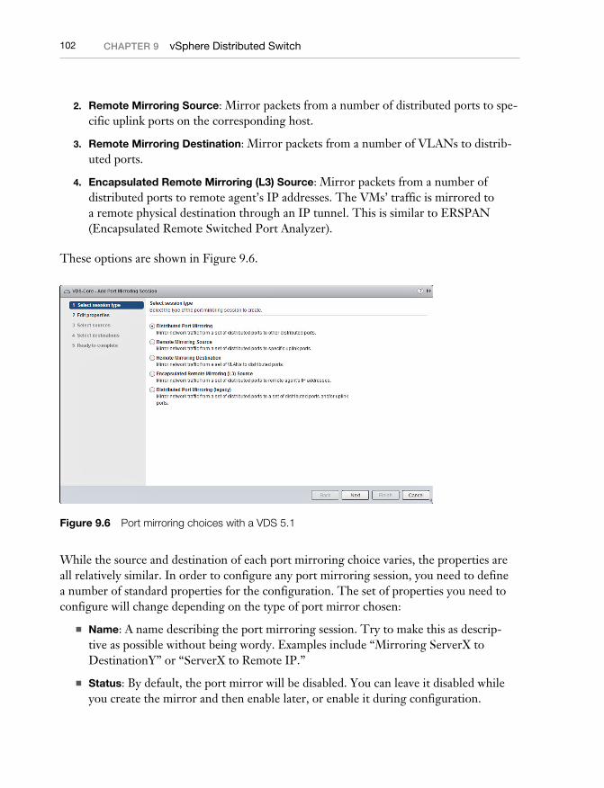
2. Remote Mirroring Source: Mirror packets from a number of distributed ports to spe-cific uplink ports on the corresponding host.
3. Remote Mirroring Destination: Mirror packets from a number of VLANs to distrib-uted ports.
4. Encapsulated Remote Mirroring (L3) Source: Mirror packets from a number of distributed ports to remote agent’s IP addresses. The VMs’ traffic is mirrored to a remote physical destination through an IP tunnel. This is similar to ERSPAN (Encapsulated Remote Switched Port Analyzer).
These options are shown in Figure 9.6.
Figure 9.6 Port mirroring choices with a VDS 5.1
While the source and destination of each port mirroring choice varies, the properties are all relatively similar. In order to configure any port mirroring session, you need to define a number of standard properties for the configuration. The set of properties you need to configure will change depending on the type of port mirror chosen:
■ Name: A name describing the port mirroring session. Try to make this as descrip-tive as possible without being wordy. Examples include “Mirroring ServerX to DestinationY” or “ServerX to Remote IP.”
■ Status: By default, the port mirror will be disabled. You can leave it disabled while you create the mirror and then enable later, or enable it during configuration.
09_9780133511086_ch09.indd 10209_9780133511086_ch09.indd 102 2/25/14 8:42 PM2/25/14 8:42 PM
103Monitoring
■ Session Type: This selects the type of port mirroring session. Choose one of the four described in the previous list.
■ Encapsulation VLAN ID: The VLAN specified here will be used to encapsulate the frames that are being mirrored. This will allow you to ship frames across an uplink that might use a different VLAN ID. If you want the port mirror to remember the original VLAN ID that the traffic was using, make sure to check the “Preserve Original VLAN” option. Otherwise, the encapsulation VLAN will take its place.
There are also a few advanced properties that can be tweaked. Not all of them will be available for each port mirror type, but we cover all of them in this section:
■ Normal I/O on destination ports: The description on this is a bit vague. It is asking you to decide if you want the destination port to act simply as a port mirror port, or if it should accept incoming traffic. By default it is set to “Disallowed” which pre-vents the destination port from accepting traffic into the port and effectively dedi-cates the port to the port mirror. For most monitoring applications that simply wish to interrogate traffic, leaving the value at “Disallowed” is desired. Keep in mind that this also prevents the port from transmitting traffic.
■ Mirror packet length (Bytes): This is a size limitation imposed on the mirrored traf-fic. If you do specify a size, packets that exceed the size will be truncated to the size you specified. This can be handy if you are monitoring traffic that includes Jumbo Frames, such as storage traffic, but only wish to capture the normal sized frames or headers rather than the full payload. Typically you’ll want to leave this field empty and specify any packet length limitations on the capture software.
■ Sampling rate: Much like with NetFlow’s sampling rate configuration, the port mir-ror sampling rate determines how many packets to sample. The value of 1, which is default, means to capture every packet. Any other value of N means to capture the Nth packet. For example, a sampling rate of 7 will capture every seventh packet and skip the other six.
■ Description: A description for your port mirroring session. No clue why this is listed in the Advanced properties section, as it’s a way to help convey the purpose of your session, but there you have it.
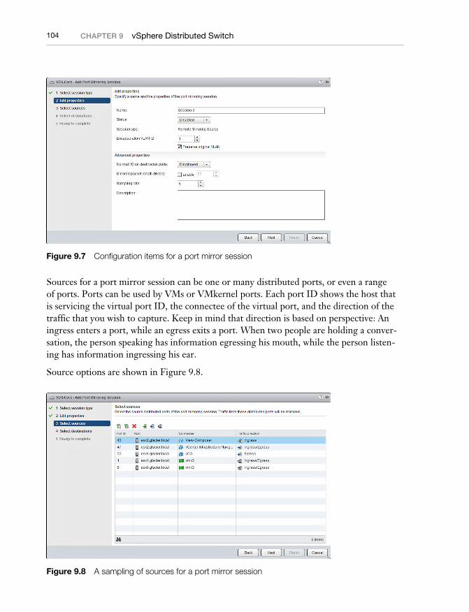
These advanced properties are shown in Figure 9.7.
09_9780133511086_ch09.indd 10309_9780133511086_ch09.indd 103 2/25/14 8:42 PM2/25/14 8:42 PM
104 CHAPTER 9 vSphere Distributed Switch
Figure 9.7 Configuration items for a port mirror session
Sources for a port mirror session can be one or many distributed ports, or even a range of ports. Ports can be used by VMs or VMkernel ports. Each port ID shows the host that is servicing the virtual port ID, the connectee of the virtual port, and the direction of the traffic that you wish to capture. Keep in mind that direction is based on perspective: An ingress enters a port, while an egress exits a port. When two people are holding a conver-sation, the person speaking has information egressing his mouth, while the person listen-ing has information ingressing his ear.
Source options are shown in Figure 9.8.
Figure 9.8 A sampling of sources for a port mirror session
09_9780133511086_ch09.indd 10409_9780133511086_ch09.indd 104 2/25/14 8:42 PM2/25/14 8:42 PM
105Private VLANs
The only exception to this is the Remote Mirroring Destination type, which uses one or more VLAN IDs as the source.
Choosing the destination for your port mirror has the most variety. Here is a list of desti-nation options for each port mirror type:
■ Distributed Port Mirroring: virtual ports
■ Remote Mirroring Source: uplinks
■ Remote Mirroring Destination: virtual ports
■ Encapsulated Remote Mirroring (L3) Source: remote IP
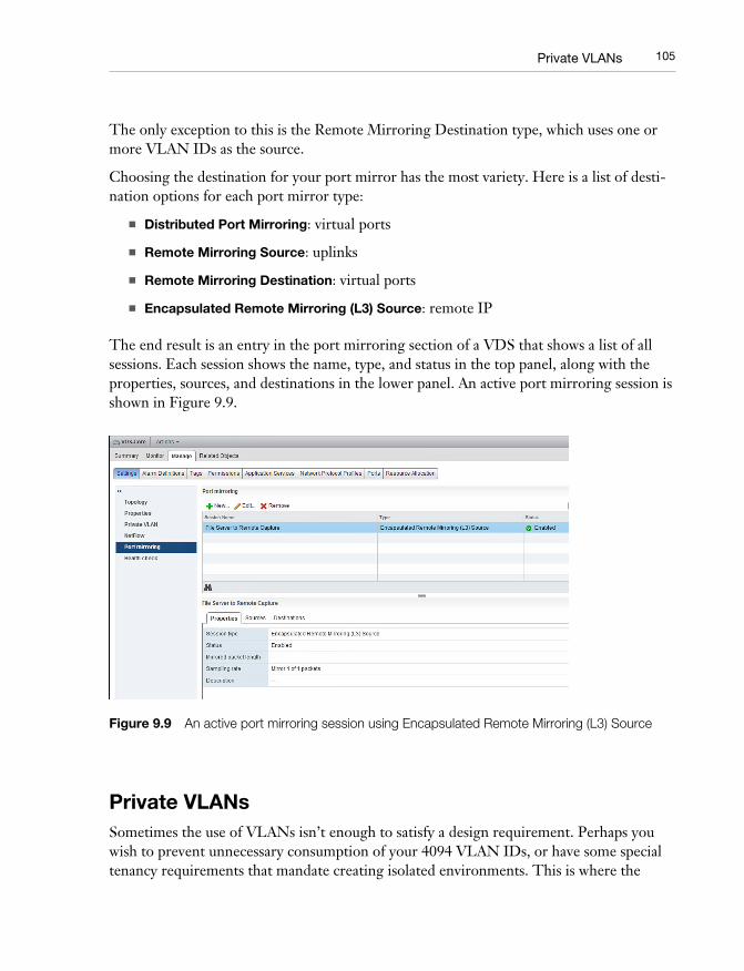
The end result is an entry in the port mirroring section of a VDS that shows a list of all sessions. Each session shows the name, type, and status in the top panel, along with the properties, sources, and destinations in the lower panel. An active port mirroring session is shown in Figure 9.9.
Figure 9.9 An active port mirroring session using Encapsulated Remote Mirroring (L3) Source
Private VLANsSometimes the use of VLANs isn’t enough to satisfy a design requirement. Perhaps you wish to prevent unnecessary consumption of your 4094 VLAN IDs, or have some special tenancy requirements that mandate creating isolated environments. This is where the
09_9780133511086_ch09.indd 10509_9780133511086_ch09.indd 105 2/25/14 8:42 PM2/25/14 8:42 PM
106 CHAPTER 9 vSphere Distributed Switch
concept of a Private VLAN comes into play. The architectural differences are sort of like comparing a single-family home to a high-rise condo building.
In the single-family home scenario, everyone lives in the same house together but they occupy different rooms. If you have access to the house, we can trust that you belong in the house and we don’t really prevent you from wandering into someone else’s room—although that’s typically not the polite thing to do. This is much like a regular VLAN. If you want to transfer from one person’s home to another, or from one VLAN to another VLAN, you have to use a routing device—you can’t just walk in between houses.
Primary VLANIn a condo building, each condo itself is an isolated environment within the larger build-ing. Everyone has access to the condo building’s front door, but not each other’s condo. This is sort of how the Private VLAN works. We use the term “Primary VLAN” to denote the common VLAN that is used to enter the private set of VLANs.
Promiscuous VLANThe Primary VLAN is connected to the rest of the network infrastructure by way of one or more promiscuous ports, also known as P-Ports. Think of the P-Port like the doorway into the condo building—everyone has access to it, and it’s how you get in and out of the private set of VLANs. Every Private VLAN needs a Primary VLAN with a P-Port, other-wise there would be no way to get traffic in and out of the networking segment.
Secondary VLANsEach condo in the building would represent a “Secondary VLAN,” or sub-VLAN, that can re-use VLAN IDs that exist outside of the Private VLAN. That is, if you have a network VLAN ID of 100 somewhere on your network, you can also have a Secondary VLAN that uses VLAN ID 100 within the scope of the Primary VLAN. However, the Primary VLAN must be unique on both networks, or else the network would become confused as to which VLAN you are intending traffic to traverse.
Secondary VLAN IDs only exist within the Private VLAN environment, and the tags are replaced with the Primary VLAN ID when traffic leaves the Private VLAN. There are three types of Secondary VLANs defined in a VMware Distributed Switch: the Promiscu-ous VLAN, which we already covered, as well as the Community and Isolated VLANs.
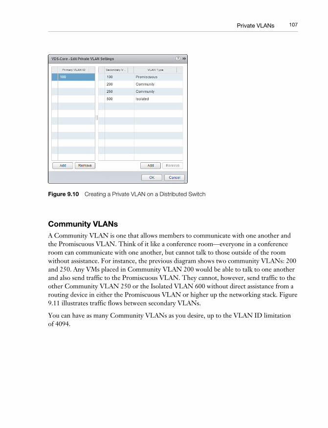
Figure 9.10 shows the process of creating a Private VLAN on a VDS.
09_9780133511086_ch09.indd 10609_9780133511086_ch09.indd 106 2/25/14 8:42 PM2/25/14 8:42 PM
107Private VLANs
Figure 9.10 Creating a Private VLAN on a Distributed Switch
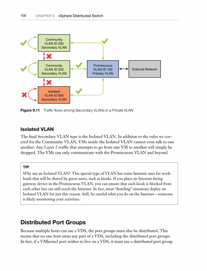
Community VLANsA Community VLAN is one that allows members to communicate with one another and the Promiscuous VLAN. Think of it like a conference room—everyone in a conference room can communicate with one another, but cannot talk to those outside of the room without assistance. For instance, the previous diagram shows two community VLANs: 200 and 250. Any VMs placed in Community VLAN 200 would be able to talk to one another and also send traffic to the Promiscuous VLAN. They cannot, however, send traffic to the other Community VLAN 250 or the Isolated VLAN 600 without direct assistance from a routing device in either the Promiscuous VLAN or higher up the networking stack. Figure 9.11 illustrates traffic flows between secondary VLANs.
You can have as many Community VLANs as you desire, up to the VLAN ID limitation of 4094.
09_9780133511086_ch09.indd 10709_9780133511086_ch09.indd 107 2/25/14 8:42 PM2/25/14 8:42 PM
108 CHAPTER 9 vSphere Distributed Switch
CommunityVLAN ID 200
Secondary VLAN
CommunityVLAN ID 250
Secondary VLAN
PromiscuousVLAN ID 100Primary VLAN
External Network
IsolatedVLAN ID 600
Secondary VLAN
Figure 9.11 Traffic flows among Secondary VLANs in a Private VLAN
Isolated VLANThe final Secondary VLAN type is the Isolated VLAN. In addition to the rules we cov-ered for the Community VLAN, VMs inside the Isolated VLAN cannot even talk to one another. Any Layer 2 traffic that attempts to go from one VM to another will simply be dropped. The VMs can only communicate with the Promiscuous VLAN and beyond.
TIP
Why use an Isolated VLAN? This special type of VLAN has some fantastic uses for work-loads that will be shared by guest users, such as kiosks. If you place an Internet facing gateway device in the Promiscuous VLAN, you can ensure that each kiosk is blocked from each other but can still reach the Internet. In fact, most “hoteling” situations deploy an Isolated VLAN for just this reason. Still, be careful what you do on the Internet—someone is likely monitoring your activities.
Distributed Port GroupsBecause multiple hosts can use a VDS, the port groups must also be distributed. This means that no one host owns any part of a VDS, including the distributed port groups. In fact, if a VMkernel port wishes to live on a VDS, it must use a distributed port group.
09_9780133511086_ch09.indd 10809_9780133511086_ch09.indd 108 2/25/14 8:42 PM2/25/14 8:42 PM
109Distributed Port Groups
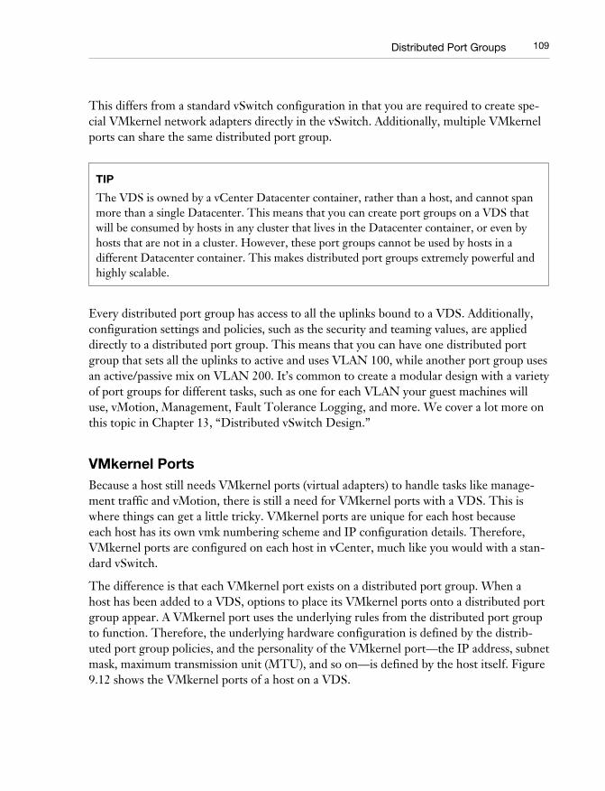
This differs from a standard vSwitch configuration in that you are required to create spe-cial VMkernel network adapters directly in the vSwitch. Additionally, multiple VMkernel ports can share the same distributed port group.
TIP
The VDS is owned by a vCenter Datacenter container , rather than a host, and cannot span more than a single Datacenter. This means that you can create port groups on a VDS that will be consumed by hosts in any cluster that lives in the Datacenter container, or even by hosts that are not in a cluster. However, these port groups cannot be used by hosts in a different Datacenter container. This makes distributed port groups extremely powerful and highly scalable.
Every distributed port group has access to all the uplinks bound to a VDS. Additionally, configuration settings and policies, such as the security and teaming values, are applied directly to a distributed port group. This means that you can have one distributed port group that sets all the uplinks to active and uses VLAN 100, while another port group uses an active/passive mix on VLAN 200. It’s common to create a modular design with a variety of port groups for different tasks, such as one for each VLAN your guest machines will use, vMotion, Management, Fault Tolerance Logging, and more. We cover a lot more on this topic in Chapter 13, “Distributed vSwitch Design.”
VMkernel PortsBecause a host still needs VMkernel ports (virtual adapters) to handle tasks like manage-ment traffic and vMotion, there is still a need for VMkernel ports with a VDS. This is where things can get a little tricky. VMkernel ports are unique for each host because each host has its own vmk numbering scheme and IP configuration details. Therefore, VMkernel ports are configured on each host in vCenter, much like you would with a stan-dard vSwitch.
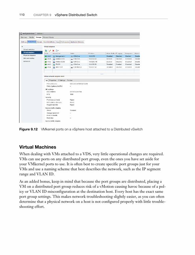
The difference is that each VMkernel port exists on a distributed port group. When a host has been added to a VDS, options to place its VMkernel ports onto a distributed port group appear. A VMkernel port uses the underlying rules from the distributed port group to function. Therefore, the underlying hardware configuration is defined by the distrib-uted port group policies, and the personality of the VMkernel port—the IP address, subnet mask, maximum transmission unit (MTU), and so on—is defined by the host itself. Figure 9.12 shows the VMkernel ports of a host on a VDS.
09_9780133511086_ch09.indd 10909_9780133511086_ch09.indd 109 2/25/14 8:42 PM2/25/14 8:42 PM
110 CHAPTER 9 vSphere Distributed Switch
Figure 9.12 VMkernel ports on a vSphere host attached to a Distributed vSwitch
Virtual MachinesWhen dealing with VMs attached to a VDS, very little operational changes are required. VMs can use ports on any distributed port group, even the ones you have set aside for your VMkernel ports to use. It is often best to create specific port groups just for your VMs and use a naming scheme that best describes the network, such as the IP segment range and VLAN ID.
As an added bonus, keep in mind that because the port groups are distributed, placing a VM on a distributed port group reduces risk of a vMotion causing havoc because of a pol-icy or VLAN ID misconfiguration at the destination host. Every host has the exact same port group settings. This makes network troubleshooting slightly easier, as you can often determine that a physical network on a host is not configured properly with little trouble-shooting effort.
09_9780133511086_ch09.indd 11009_9780133511086_ch09.indd 110 2/25/14 8:42 PM2/25/14 8:42 PM

111Traffi c Shaping
Traffic ShapingWe’ve already gone rather deep into the concept and math behind traffic shaping in Chap-ter 8, “vSphere Standard Switch.” You should be well versed with how to define your aver-age, peak, and burst sizes—if not, go back a chapter and read the traffic shaping section.
The reason we go into traffic shaping a second time is due to the additional feature found in the Distributed vSwitch—the ability to perform both ingress and egress traffic shaping. The standard vSwitch is limited to ingress shaping only.
EgressEgress is the concept of controlling traffic that leaves the VDS. This could be from the VDS to a VM or a VMkernel port, or even as the traffic flows from one VM to another. The traffic shaping configuration options are the same as with ingress shaping, but are applied for traffic flowing in the other direction. Such traffic is illustrated in Figure 9.13.
VirtualMachine
VMkernel PortEgress
Egress
Ingress
PhysicalUpstream
SwitchDistributedvSwitch(VDS)
VirtualMachine
uplink
Figure 9.13 Multiple ways egress traffic can occur in a VDS
NOTE
One really great way to use egress traffic shaping is to control the amount of bandwidth that can be used for multi-NIC vMotion traffic. A corner case exists where multiple source hosts might be vMotioning VMs to a single destination host. Without egress traffic shaping, or some sort of physical traffic shaping on the upstream switch, you might end up experi-encing a non-trivial amount of traffic on your host uplinks. We cover this in greater detail in Chapter 19, “Multi-NIC vMotion Architecture.”
09_9780133511086_ch09.indd 11109_9780133511086_ch09.indd 111 2/25/14 8:42 PM2/25/14 8:42 PM
112 CHAPTER 9 vSphere Distributed Switch
Load BalancingAnother feature that is only available in the Distributed vSwitch is a new form of load bal-ancing named “route based on physical NIC load” which is often referred to as Load Based Teaming (LBT) . This routing policy was first introduced with vSphere 4.1 and is the only true active load balancing policy available to you. All the other policies use an arbitrary factor to determine the uplink path, such as the IP address or virtual port, whereas LBT actively monitors and shifts traffic to various uplinks when certain criteria are met.
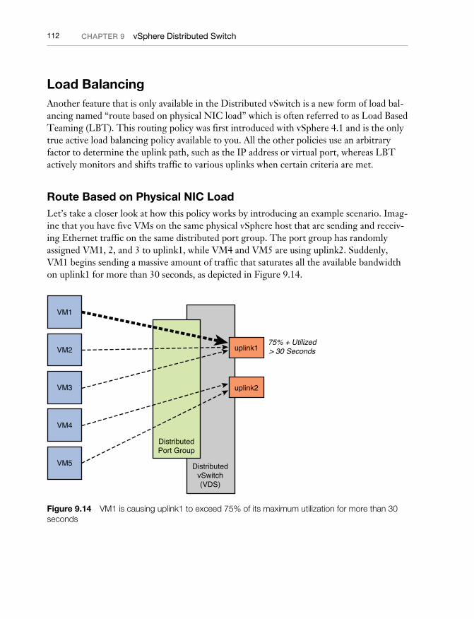
Route Based on Physical NIC LoadLet’s take a closer look at how this policy works by introducing an example scenario. Imag-ine that you have five VMs on the same physical vSphere host that are sending and receiv-ing Ethernet traffic on the same distributed port group. The port group has randomly assigned VM1, 2, and 3 to uplink1, while VM4 and VM5 are using uplink2. Suddenly, VM1 begins sending a massive amount of traffic that saturates all the available bandwidth on uplink1 for more than 30 seconds, as depicted in Figure 9.14.
VM1
VM2
VM3
VM4
VM5
DistributedPort Group
DistributedvSwitch(VDS)
uplink175% + Utilized> 30 Seconds
uplink2
Figure 9.14 VM1 is causing uplink1 to exceed 75% of its maximum utilization for more than 30 seconds
09_9780133511086_ch09.indd 11209_9780133511086_ch09.indd 112 2/25/14 8:42 PM2/25/14 8:42 PM
113Load Balancing
With any other load balancing policy, the saturation on uplink1 would continue until VM1 finished sending data across the network. Meanwhile, uplink2 might be experiencing very little traffic or even be idle. What a waste!
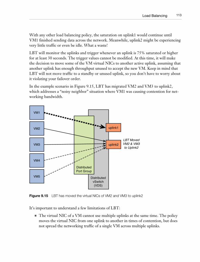
LBT will monitor the uplinks and trigger whenever an uplink is 75% saturated or higher for at least 30 seconds. The trigger values cannot be modified. At this time, it will make the decision to move some of the VM virtual NICs to another active uplink, assuming that another uplink has enough throughput unused to accept the new VM. Keep in mind that LBT will not move traffic to a standby or unused uplink, so you don’t have to worry about it violating your failover order.
In the example scenario in Figure 9.15, LBT has migrated VM2 and VM3 to uplink2, which addresses a “noisy neighbor” situation where VM1 was causing contention for net-working bandwidth.
VM1
VM2
VM3
VM4
VM5
DistributedPort Group
DistributedvSwitch(VDS)
uplink1
LBT MovedVM2 & VM3to Uplink2
uplink2
Figure 9.15 LBT has moved the virtual NICs of VM2 and VM3 to uplink2
It’s important to understand a few limitations of LBT:
■ The virtual NIC of a VM cannot use multiple uplinks at the same time. The policy moves the virtual NIC from one uplink to another in times of contention, but does not spread the networking traffic of a single VM across multiple uplinks.
09_9780133511086_ch09.indd 11309_9780133511086_ch09.indd 113 2/25/14 8:42 PM2/25/14 8:42 PM
114 CHAPTER 9 vSphere Distributed Switch
■ If you have very bursty traffic that finishes in less than 30 seconds, LBT does not trigger a migration. This 30-second threshold exists to prevent thrashing: useless, repetitive, expensive work.
NOTE
Although almost all documentation for LBT talks about the ability to migrate VM virtual NICs, it’s important to understand that it can also move around VMkernel ports. If you are in a converged infrastructure environment with a limited number of uplinks, it might be advantageous to use LBT to move around your VMkernel port assigned to management or vMotion in times of uplink bandwidth saturation. Don’t forget that LBT cannot cause traffic for a VMkernel port to use multiple uplinks simultaneously—it will only move the VMkernel port from one uplink to another.
You might wonder how LBT works when you have multiple distributed port groups all sharing the same set of uplinks. After all, each port group can have a different teaming policy applied, with some using LBT, others using virtual port ID, and perhaps a few using an explicit failover order. Fortunately, because LBT monitors saturation on the uplinks, it mixes with other policies very well. If any uplink in the VDS becomes saturated at 75% or higher for 30 seconds, any distributed port group with the LBT policy configured triggers and attempts to move around workloads. There is no need to have one giant port group with all the VMs inside.
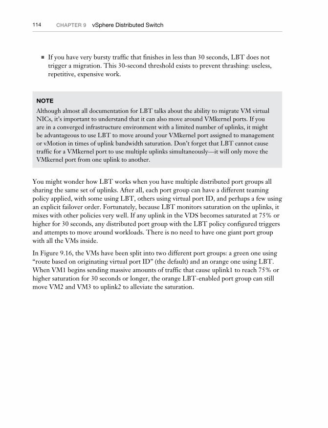
In Figure 9.16, the VMs have been split into two different port groups: a green one using “route based on originating virtual port ID” (the default) and an orange one using LBT. When VM1 begins sending massive amounts of traffic that cause uplink1 to reach 75% or higher saturation for 30 seconds or longer, the orange LBT-enabled port group can still move VM2 and VM3 to uplink2 to alleviate the saturation.
09_9780133511086_ch09.indd 11409_9780133511086_ch09.indd 114 2/25/14 8:42 PM2/25/14 8:42 PM
115Network I/O Control
VM1
VM2
VM3
VM4
VM5
Virtual PortID
DistributedPort Groups
Physical NICLoad
DistributedvSwitch(VDS)
uplink1
LBT will MoveVM2 & VM3to Uplink2
uplink2
Figure 9.16 A workload on a “route based on virtual port ID” port group can still cause LBT to move workloads elsewhere
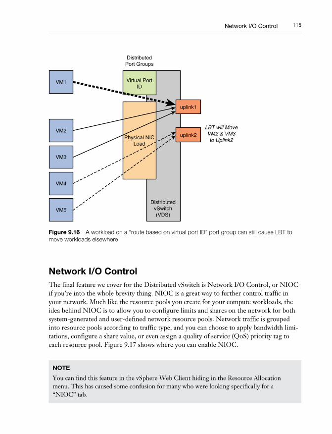
Network I/O ControlThe final feature we cover for the Distributed vSwitch is Network I/O Control, or NIOC if you’re into the whole brevity thing. NIOC is a great way to further control traffic in your network. Much like the resource pools you create for your compute workloads, the idea behind NIOC is to allow you to configure limits and shares on the network for both system-generated and user-defined network resource pools. Network traffic is grouped into resource pools according to traffic type, and you can choose to apply bandwidth limi-tations, configure a share value, or even assign a quality of service (QoS) priority tag to each resource pool. Figure 9.17 shows where you can enable NIOC.
NOTE
You can find this feature in the vSphere Web Client hiding in the Resource Allocation menu. This has caused some confusion for many who were looking specifically for a “NIOC” tab.
09_9780133511086_ch09.indd 11509_9780133511086_ch09.indd 115 2/25/14 8:42 PM2/25/14 8:42 PM
116 CHAPTER 9 vSphere Distributed Switch
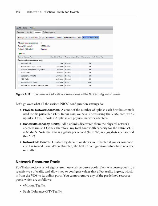
Figure 9.17 The Resource Allocation screen shows all the NIOC configuration values
Let’s go over what all the various NIOC configuration settings do:
■ Physical Network Adapters: A count of the number of uplinks each host has contrib-uted to this particular VDS. In our case, we have 3 hosts using the VDS, each with 2 uplinks. Thus, 3 hosts x 2 uplinks = 6 physical network adapters.
■ Bandwidth capacity (Gbit/s): All 6 uplinks discovered from the physical network adapters run at 1 Gbit/s; therefore, my total bandwidth capacity for the entire VDS is 6 Gbit/s. Note that this is gigabits per second (little “b”) not gigabytes per second (big “B”).
■ Network I/O Control: Disabled by default, or shows you Enabled if you or someone else has turned it on. When Disabled, the NIOC configuration values have no effect on traffic.
Network Resource PoolsYou’ll also notice a list of eight system network resource pools. Each one corresponds to a specific type of traffic and allows you to configure values that affect traffic ingress, which is from the VDS to its uplink ports. You cannot remove any of the predefined resource pools, which are as follows:
■ vMotion Traffic.
■ Fault Tolerance (FT) Traffic.
09_9780133511086_ch09.indd 11609_9780133511086_ch09.indd 116 2/25/14 8:42 PM2/25/14 8:42 PM
117Network I/O Control
■ vSphere Replication (VR) Traffic: Used by the VR appliance, including VMware Site Recovery Manager (SRM).
■ iSCSI Traffic.
■ Management Traffic.
■ NFS Traffic.
■ Virtual Machine Traffic: Used for all VMs, although you can create your own user-defined resource pools. We cover that later in this chapter.
■ vSphere SAN Traffic: Used by the Virtual SAN technology that VMware announced at VMworld 2013 (vSphere 5.5 or higher only).
Now that you know what types of traffic we can control, let’s review the configurations for each:
■ Host Limit (Mbps): A traffic limit, defined in megabits per second, which cannot be exceeded by the network resource pool. In vSphere 5.1, this is on a per-uplink basis, whereas prior to 5.1, it was a per-host limit. As an example with a 5.1 VDS: If you were to limit the vMotion network resource pool to 2000 Mbps, but defined mul-tiple vMotion VMkernel ports on multiple uplinks, each uplink could send traffic upstream at a rate of 2000 Mbps. Use limits sparingly as they might artificially create network contention for no reason.
■ Physical Adapter Shares: The configured shares for an adapter (uplink port). You can choose High (100 shares), Normal (50 shares), Low (25 shares), or Custom to define a custom quantity of shares up to 100. Shares are ultimately used to calcu-late what percentage each network resource pool can claim from a physical adapter (uplink). The speed of the uplink does not increase or decrease the number of shares because percentages are relative to the speed of the uplink.
■ Shares Value: The amount of shares set on the network resource pool.
■ QoS Priority Tag: This field gives you the ability to set the IEEE 802.1p QoS tag. Values range from 0 (lowest) to 7 (highest) priority. Many Layer 2 devices on the physical network will inspect this portion of the Ethernet frame and, based on the QoS tag value assigned, prioritize or drop traffic. Use with caution and make sure to include your network team in the discussion.
SharesShares cause the most confusion when it comes to resource pools. As such, let’s address the share values set on the network resource pools. First off, shares are a relative value. They don’t represent a specific quantity of traffic, and are not used unless the uplink becomes saturated with traffic.
09_9780133511086_ch09.indd 11709_9780133511086_ch09.indd 117 2/25/14 8:42 PM2/25/14 8:42 PM
118 CHAPTER 9 vSphere Distributed Switch
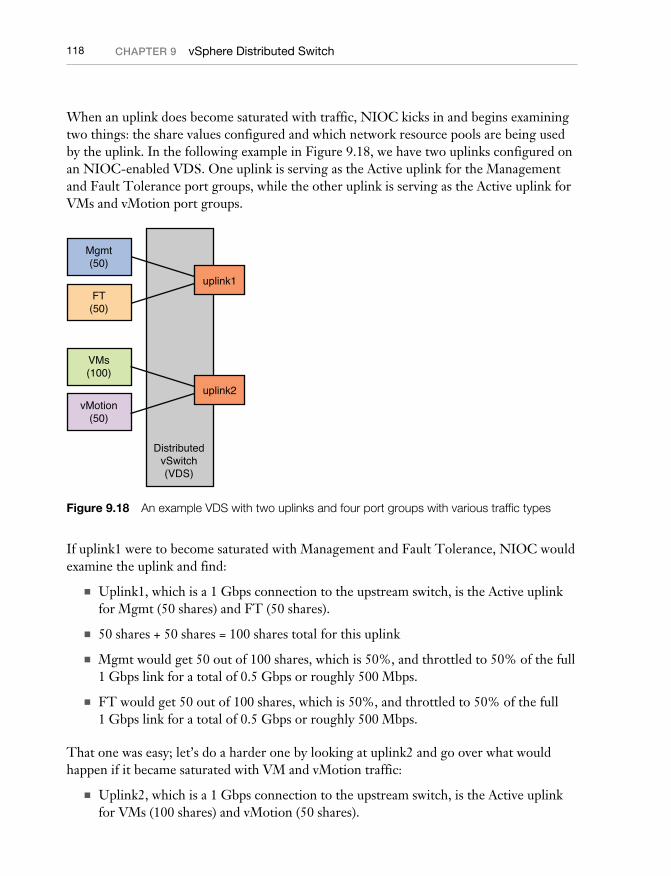
When an uplink does become saturated with traffic, NIOC kicks in and begins examining two things: the share values configured and which network resource pools are being used by the uplink. In the following example in Figure 9.18, we have two uplinks configured on an NIOC-enabled VDS. One uplink is serving as the Active uplink for the Management and Fault Tolerance port groups, while the other uplink is serving as the Active uplink for VMs and vMotion port groups.
VMs(100)
vMotion(50)
DistributedvSwitch(VDS)
uplink1
uplink2
Mgmt(50)
FT(50)
Figure 9.18 An example VDS with two uplinks and four port groups with various traffic types
If uplink1 were to become saturated with Management and Fault Tolerance, NIOC would examine the uplink and find:
■ Uplink1, which is a 1 Gbps connection to the upstream switch, is the Active uplink for Mgmt (50 shares) and FT (50 shares).
■ 50 shares + 50 shares = 100 shares total for this uplink
■ Mgmt would get 50 out of 100 shares, which is 50%, and throttled to 50% of the full 1 Gbps link for a total of 0.5 Gbps or roughly 500 Mbps.
■ FT would get 50 out of 100 shares, which is 50%, and throttled to 50% of the full 1 Gbps link for a total of 0.5 Gbps or roughly 500 Mbps.
That one was easy; let’s do a harder one by looking at uplink2 and go over what would happen if it became saturated with VM and vMotion traffic:
■ Uplink2, which is a 1 Gbps connection to the upstream switch, is the Active uplink for VMs (100 shares) and vMotion (50 shares).
09_9780133511086_ch09.indd 11809_9780133511086_ch09.indd 118 2/25/14 8:42 PM2/25/14 8:42 PM
119Network I/O Control
■ 100 shares + 50 shares = 150 shares total for this uplink
■ VMs would get 100 out of 150 shares, which is 66.7%, and throttled to 66.7% of the full 1 Gbps link for a total of 0.667 Gbps or roughly 667 Mbps.
■ vMotion would get 50 out of 150 shares, which is 33.3%, and throttled to 33.3% of the full 1 Gbps link for a total of 0.333 Gbps or roughly 333 Mbps.
Remember that shares only kick in to control active traffic. In the same scenario we just reviewed, we assume that both VMs and vMotion traffic were active and causing conten-tion. If the entire uplink were taken up with only VM traffic, and no vMotions were occur-ring, no throttling would occur—there’s only one type of active traffic (VM traffic). The VMs would get 100% of the uplink until a vMotion occurred.
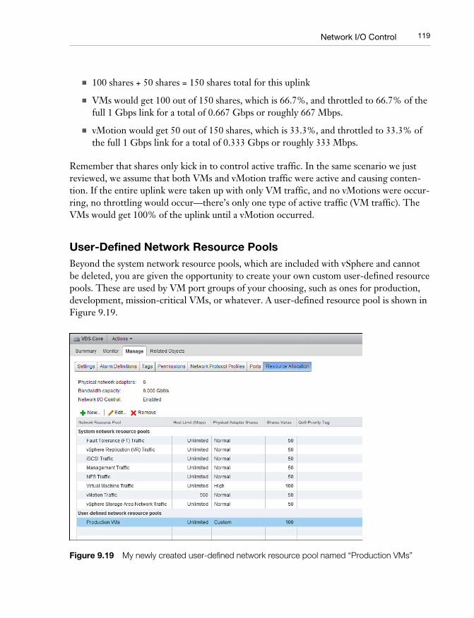
User-Defined Network Resource PoolsBeyond the system network resource pools, which are included with vSphere and cannot be deleted, you are given the opportunity to create your own custom user-defined resource pools. These are used by VM port groups of your choosing, such as ones for production, development, mission-critical VMs, or whatever. A user-defined resource pool is shown in Figure 9.19.
Figure 9.19 My newly created user-defined network resource pool named “Production VMs”
09_9780133511086_ch09.indd 11909_9780133511086_ch09.indd 119 2/25/14 8:42 PM2/25/14 8:42 PM
120 CHAPTER 9 vSphere Distributed Switch
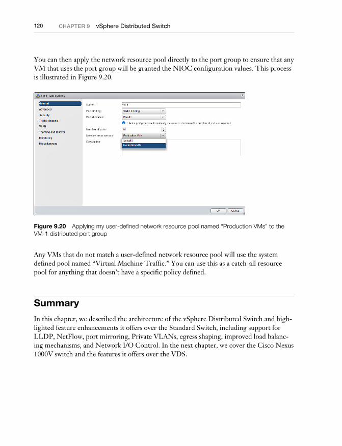
You can then apply the network resource pool directly to the port group to ensure that any VM that uses the port group will be granted the NIOC configuration values. This process is illustrated in Figure 9.20.
Figure 9.20 Applying my user-defined network resource pool named “Production VMs” to the VM-1 distributed port group
Any VMs that do not match a user-defined network resource pool will use the system defined pool named “Virtual Machine Traffic.” You can use this as a catch-all resource pool for anything that doesn’t have a specific policy defined.
Summary
In this chapter, we described the architecture of the vSphere Distributed Switch and high-lighted feature enhancements it offers over the Standard Switch, including support for LLDP, NetFlow, port mirroring, Private VLANs, egress shaping, improved load balanc-ing mechanisms, and Network I/O Control. In the next chapter, we cover the Cisco Nexus 1000V switch and the features it offers over the VDS.
09_9780133511086_ch09.indd 12009_9780133511086_ch09.indd 120 2/25/14 8:42 PM2/25/14 8:42 PM