Embed Size (px)
Citation preview
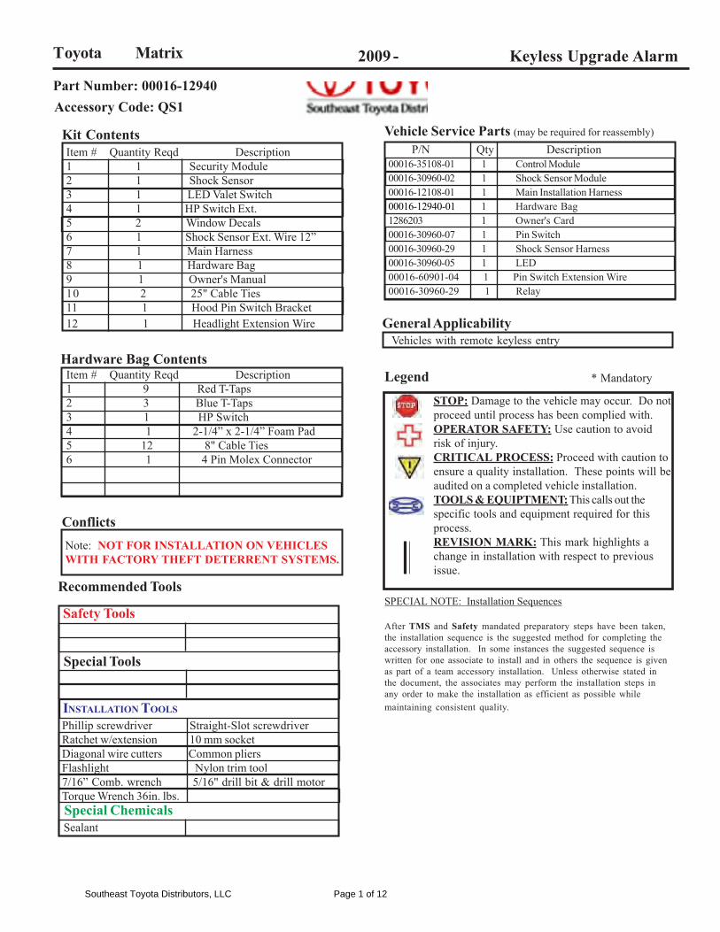
2009 - Keyless Upgrade Alarm
P/N Qty Description00016-35108-01 1 Control Module00016-30960-02 1 Shock Sensor Module00016-12108-01 1 Main Installation Harness00016-12940-01 1 Hardware Bag1286203 1 Owner's Card00016-30960-07 1 Pin Switch00016-30960-29 1 Shock Sensor Harness00016-30960-05 1 LED00016-60901-04 1 Pin Switch Extension Wire00016-30960-29 1 Relay
Phillip screwdriver Straight-Slot screwdriverRatchet w/extension 10 mm socketDiagonal wire cutters Common pliersFlashlight Nylon trim tool7/16” Comb. wrench 5/16" drill bit & drill motorTorque Wrench 36in. lbs.
Item # Quantity Reqd Description1 9 Red T-Taps2 3 Blue T-Taps3 1 HP Switch4 1 2-1/4” x 2-1/4” Foam Pad5 12 8" Cable Ties6 1 4 Pin Molex Connector
Item # Quantity Reqd Description1 1 Security Module2 1 Shock Sensor3 1 LED Valet Switch4 1 HP Switch Ext.5 2 Window Decals6 1 Shock Sensor Ext. Wire 12”7 1 Main Harness8 1 Hardware Bag9 1 Owner's Manual10 2 25" Cable Ties11 1 Hood Pin Switch Bracket12 1 Headlight Extension Wire
Kit Contents
Hardware Bag Contents
ConflictsNote: NOT FOR INSTALLATION ON VEHICLESWITH FACTORY THEFT DETERRENT SYSTEMS.
General Applicability
Legend * Mandatory
STOP: Damage to the vehicle may occur. Do notproceed until process has been complied with.OPERATOR SAFETY: Use caution to avoidrisk of injury.CRITICAL PROCESS: Proceed with caution toensure a quality installation. These points will beaudited on a completed vehicle installation.TOOLS & EQUIPTMENT: This calls out thespecific tools and equipment required for thisprocess.REVISION MARK: This mark highlights achange in installation with respect to previousissue.
Recommended ToolsSPECIAL NOTE: Installation Sequences
After TMS and Safety mandated preparatory steps have been taken,the installation sequence is the suggested method for completing theaccessory installation. In some instances the suggested sequence iswritten for one associate to install and in others the sequence is givenas part of a team accessory installation. Unless otherwise stated inthe document, the associates may perform the installation steps inany order to make the installation as efficient as possible whilemaintaining consistent quality.
Safety Tools
Special Tools
INSTALLATION TOOLS
Special Chemicals
Vehicle Service Parts (may be required for reassembly)
Toyota Matrix
Vehicles with remote keyless entry
Part Number: 00016-12940Accessory Code: QS1
Sealant
Southeast Toyota Distributors, LLC Page 1 of 12
INSTALLATION PREPARATION
Before starting installation
1. Familiarize yourself with the installation instructions.2. Inspect kit components.
VEHICLE PREPARATION
1. Place protective coverings on vehicle.
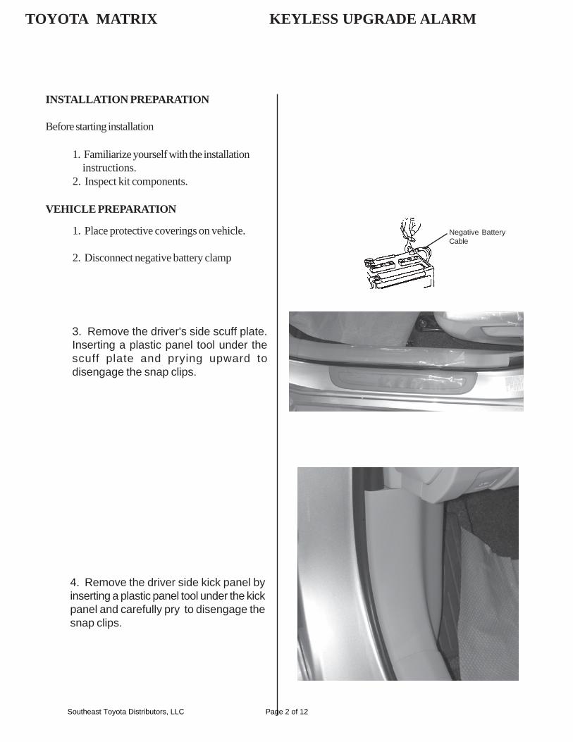
2. Disconnect negative battery clamp
Negative BatteryCable
3. Remove the driver's side scuff plate.Inserting a plastic panel tool under thescuff plate and prying upward todisengage the snap clips.
4. Remove the driver side kick panel byinserting a plastic panel tool under the kickpanel and carefully pry to disengage thesnap clips.
TOYOTA MATRIX KEYLESS UPGRADE ALARM
Southeast Toyota Distributors, LLC Page 2 of 12
TOYOTA MATRIX KEYLESS UPGRADE ALARM
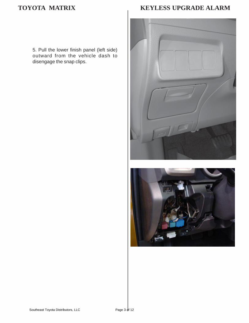
5. Pull the lower finish panel (left side)outward from the vehicle dash todisengage the snap clips.
Southeast Toyota Distributors, LLC Page 3 of 12
INSTALLING PROCEDURES
MOUNTING THE LED/VALET SWITCH:
TOYOTA MATRIX KEYLESS UPGRADE ALARM
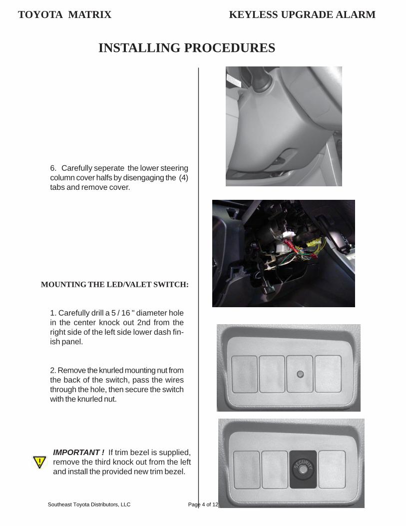
1. Carefully drill a 5 / 16 " diameter holein the center knock out 2nd from theright side of the left side lower dash fin-ish panel.
2. Remove the knurled mounting nut fromthe back of the switch, pass the wiresthrough the hole, then secure the switchwith the knurled nut.
IMPORTANT ! If trim bezel is supplied,remove the third knock out from the leftand install the provided new trim bezel.
6. Carefully seperate the lower steeringcolumn cover halfs by disengaging the (4)tabs and remove cover.
Southeast Toyota Distributors, LLC Page 4 of 12
MOUNTING SHOCK SENSOR MODULE:
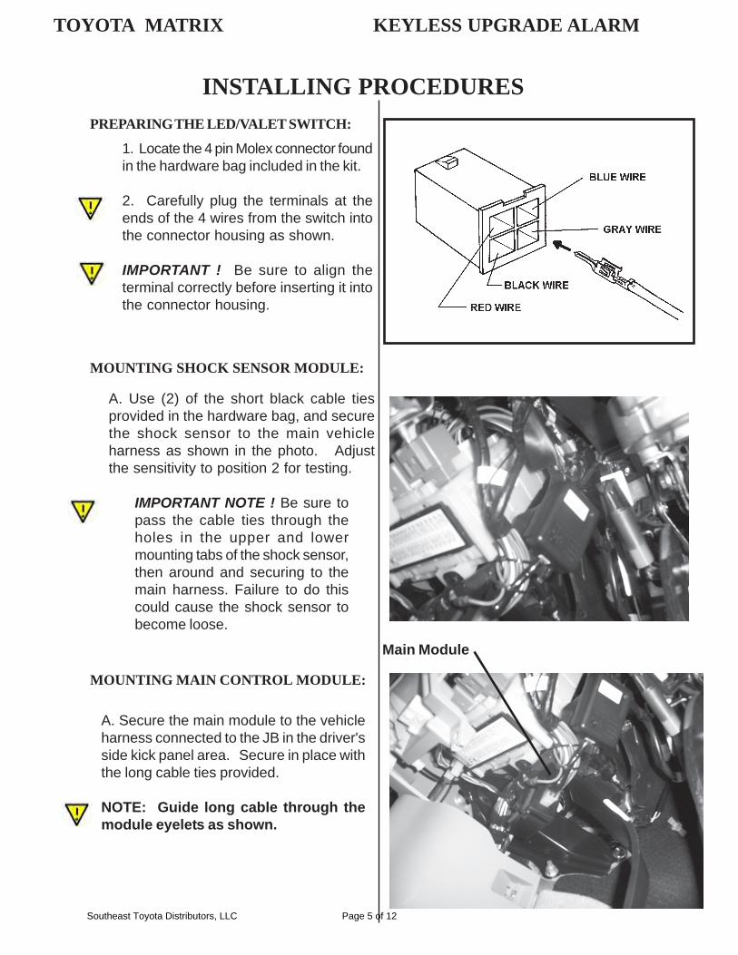
A. Use (2) of the short black cable tiesprovided in the hardware bag, and securethe shock sensor to the main vehicleharness as shown in the photo. Adjustthe sensitivity to position 2 for testing.
IMPORTANT NOTE ! Be sure topass the cable ties through theholes in the upper and lowermounting tabs of the shock sensor,then around and securing to themain harness. Failure to do thiscould cause the shock sensor tobecome loose.
MOUNTING MAIN CONTROL MODULE:
PREPARING THE LED/VALET SWITCH:
1. Locate the 4 pin Molex connector foundin the hardware bag included in the kit.
2. Carefully plug the terminals at theends of the 4 wires from the switch intothe connector housing as shown.
IMPORTANT ! Be sure to align theterminal correctly before inserting it intothe connector housing.
INSTALLING PROCEDURES
TOYOTA MATRIX KEYLESS UPGRADE ALARM
A. Secure the main module to the vehicleharness connected to the JB in the driver'sside kick panel area. Secure in place withthe long cable ties provided.
NOTE: Guide long cable through themodule eyelets as shown.
SHOCK SENSOR
Main Module
Southeast Toyota Distributors, LLC Page 5 of 12
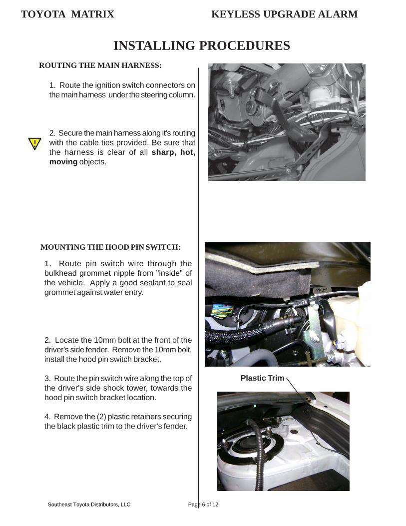
ROUTING THE MAIN HARNESS:
1. Route the ignition switch connectors onthe main harness under the steering column.
2. Secure the main harness along it's routingwith the cable ties provided. Be sure thatthe harness is clear of all sharp, hot,moving objects.
INSTALLING PROCEDURES
TOYOTA MATRIX KEYLESS UPGRADE ALARM
MOUNTING THE HOOD PIN SWITCH:
1. Route pin switch wire through thebulkhead grommet nipple from "inside" ofthe vehicle. Apply a good sealant to sealgrommet against water entry.
2. Locate the 10mm bolt at the front of thedriver's side fender. Remove the 10mm bolt,install the hood pin switch bracket.
3. Route the pin switch wire along the top ofthe driver's side shock tower, towards thehood pin switch bracket location.
4. Remove the (2) plastic retainers securingthe black plastic trim to the driver's fender.
Plastic Trim
Southeast Toyota Distributors, LLC Page 6 of 12

INSTALLING THE SHOCK SENSOR HAR-NESS:
1. Plug the 5 pin end of the harness intothe matting connector on the main controlmodule.
2. Route the harness towards the shocksensor, where it will not interfere with anysharp or moving objects.
3. Secure the harness along the routingpath using the cable ties provided.
IMPORTANT ! After installation, inspect & insure that all Security SystemHarness are clear of all HOT, SHARP or MOVING objects
CONNECTING THE SECURITY SYSTEMHARNESS:
T-TAP INSTALLATION:
A. When installing female T - Tap connectors, be sure the wire is located inside the wire channel of thefemale T - Tap connector before closing connector over the wire with pliers ( Figure D ).
Step A Step B Step C
T - Tap Wire from main security harness
TOYOTA MATRIX KEYLESS UPGRADE ALARM
5. Install "star washer" nut on pin switch wireand connect pin switch wire to pin switch asshown.
6. Thread "starwasher" nut on pin switch andtighten.
7. Using a foam pad, secure the hood pinswitch wire to the fender support.
8. Re-assemble the black plastic trim panel.
1. Carefully follow the wiring diagram andfactory connector details on pages 8-10.
MOUNTING THE HOOD PIN SWITCH:
Southeast Toyota Distributors, LLC Page 7 of 12
WIR
ING
DIA
GR
AM
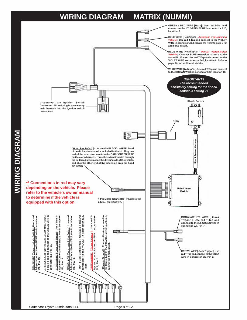
4 Pin Molex Connector - Plug Into theL.E.D. / Valet Switch.
[ Hood Pin Switch ] - Locate the BLACK / WHITE hoodpin switch extension wire included in the kit. Plug oneend of the extension wire into the DARK GREEN WIREon the alarm harness, route the extension wire throughthe bulkhead grommet on the driver's side of the vehicle,and plug the other end of the extension onto the hoodpin switch.
Shock Sensor
Disconnect the Ignition SwitchConnector E5 and plug in the securitymain harness into the ignition switchconnectors.
BROWN/WHITE WIRE [ TrunkTrigger ]: Use red T-Tap andconnect to the LT. GREEN wire inconnector 2A, Pin 7.
Relay
10 A
MP
FUS
E
PIN
K/W
HIT
E [D
river
Unl
ock
Switc
h]:
Use
a r
edT-
Tap
and
conn
ect t
o th
e B
EIG
E w
ire in
con
nect
orIE
2, P
in 1
5.
GR
EEN
/BLA
CK
[ D
river
Doo
r Unl
ock
Mot
or ]
: Use
a bl
ue T
-Tap
and
con
nect
to th
e G
REE
N w
ire in
conn
ecto
r IE
2 Pi
n 1
7.
BLU
E/W
HIT
E [
Doo
r Loc
k M
otor
]: U
se a
blu
e T-
Tap
and
conn
ect t
o th
e B
EIG
E w
ire in
con
nect
orIE
2, P
in
8.
PIN
K/B
LAC
K [D
oor U
nloc
k K
ey S
witc
h ]:
Use
a re
dT-
Tap
and
conn
ect t
o th
e PI
NK
wire
in c
onne
ctor
IE2,
Pin
6.
PIN
K
[ Doo
r Loc
k Sw
itch
]: U
se a
red
T-Ta
p an
dco
nnec
tor
to t
he V
IOLE
T in
con
nect
or I
E2,
Pin
16.
GR
EEN
/WH
ITE
[ T
runk
Rel
ease
]: U
se a
red
T-Ta
p an
d co
nnec
tor
to t
he P
INK
in
con
nect
orEL
1, P
in 2
.
[ Cha
ssis
Gro
und
]: C
onne
ct th
e rin
g te
rmin
al to
the
10 m
m b
olt t
o th
e le
ft of
the
stee
ring
colu
mn,
behi
nd t
he f
inis
h pa
nel..
IMPORTANT !The recommended
sensitivity setting for the shocksensor is setting 2 !
WIRING DIAGRAM MATRIX (NUMMI)
BROWN WIRE [ Door Trigger ]: Usered T-Tap and connect to the GRAYwire in connector 2K, Pin 2.
GREEN / RED WIRE [Horn]: Use red T-Tap andconnect to the LT. GREEN WIRE in connector E10,location 8.
BLUE WIRE [Headlights - Automatic TransmissionVehicle]: Use red T-Tap and connect to the VIOLETWIRE in connector AE4, location 6. Refer to page 9 foradditional details.
BLUE WIRE [Headlights - Manual TransmissionVehicle]: Connect BLUE extension harness to thealarm BLUE wire. Use red T-Tap and connect to theVIOLET WIRE in connector E42, location 6. Refer topage 10 for additional details.
WHITE WIRE [Tail Lights]: Use red T-Tap and connectto the BROWN WIRE in connector E12, location 18.
** Connections in red may varydepending on the vehicle. Pleaserefer to the vehicle's owner manualto determine if the vehicle isequipped with this option.
Southeast Toyota Distributors, LLC Page 8 of 12
4
9
53 6 7
13 1412 15 16
82
18
1
1711107 6 5 4 3
15 1416 13 12
1289
10111718
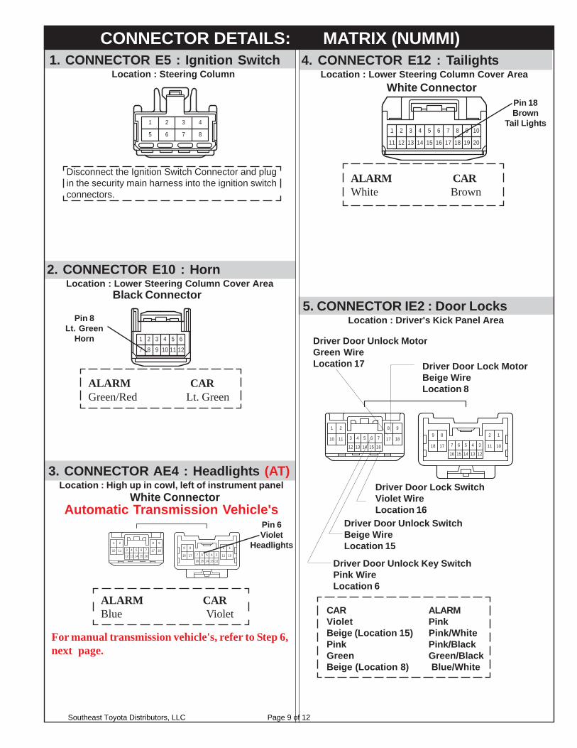
5. CONNECTOR IE2 : Door LocksLocation : Driver's Kick Panel Area
CAR ALARMViolet PinkBeige (Location 15) Pink/WhitePink Pink/BlackGreen Green/BlackBeige (Location 8) Blue/White
Driver Door Lock SwitchViolet WireLocation 16
Driver Door Unlock SwitchBeige WireLocation 15
Driver Door Unlock MotorGreen WireLocation 17 Driver Door Lock Motor
Beige WireLocation 8
Driver Door Unlock Key SwitchPink WireLocation 6
2. CONNECTOR E10 : HornLocation : Lower Steering Column Cover Area
Pin 8Lt. Green
Horn
CONNECTOR DETAILS: MATRIX (NUMMI)
Pin 6Violet
Headlights
3. CONNECTOR AE4 : Headlights (AT)Location : High up in cowl, left of instrument panel
Automatic Transmission Vehicle's
ALARM CARGreen/Red Lt. Green
Disconnect the Ignition Switch Connector and plugin the security main harness into the ignition switchconnectors.
1 2 3 4
5 6 7 8
1. CONNECTOR E5 : Ignition SwitchLocation : Steering Column
121097
641 3 5
11
2
8
ALARM CARBlue Violet
1 2 3 4 5 6 7 8 9 10
11 12 13 14 15 16 17 18 19 20
4
9
53 6 7
13 1412 15 16
82
18
1
1711107 6 5 4 3
15 1416 13 12
1289
10111718
4. CONNECTOR E12 : TailightsLocation : Lower Steering Column Cover Area
Pin 18Brown
Tail Lights
ALARM CARWhite Brown
For manual transmission vehicle's, refer to Step 6,next page.
White Connector
White Connector
Black Connector
Southeast Toyota Distributors, LLC Page 9 of 12
567 34121314 1011
29
18
123456789
101112131415161718
1234
2
1 3456
2
12
1
2
1 1
2
35
1
1
1234567810111213141516 9
45678
1
123458 7 6
23
6543
2
1
98
1110
2423
2625
1312
1514
2827
3029
6
1
5432
721
16
20191817
22
9101112
131415161718
6
1
5432
78
9101112
25262728
13141516
29303132
6
1
5432
78
22
17
21201918
2324
98
2410 2511 26
12 2713 2814 2915 30
23
1
765
222120
234
16171819
1
5 3
2
4
2A
2K
27282930
313233343536
24
19
23222120
2526
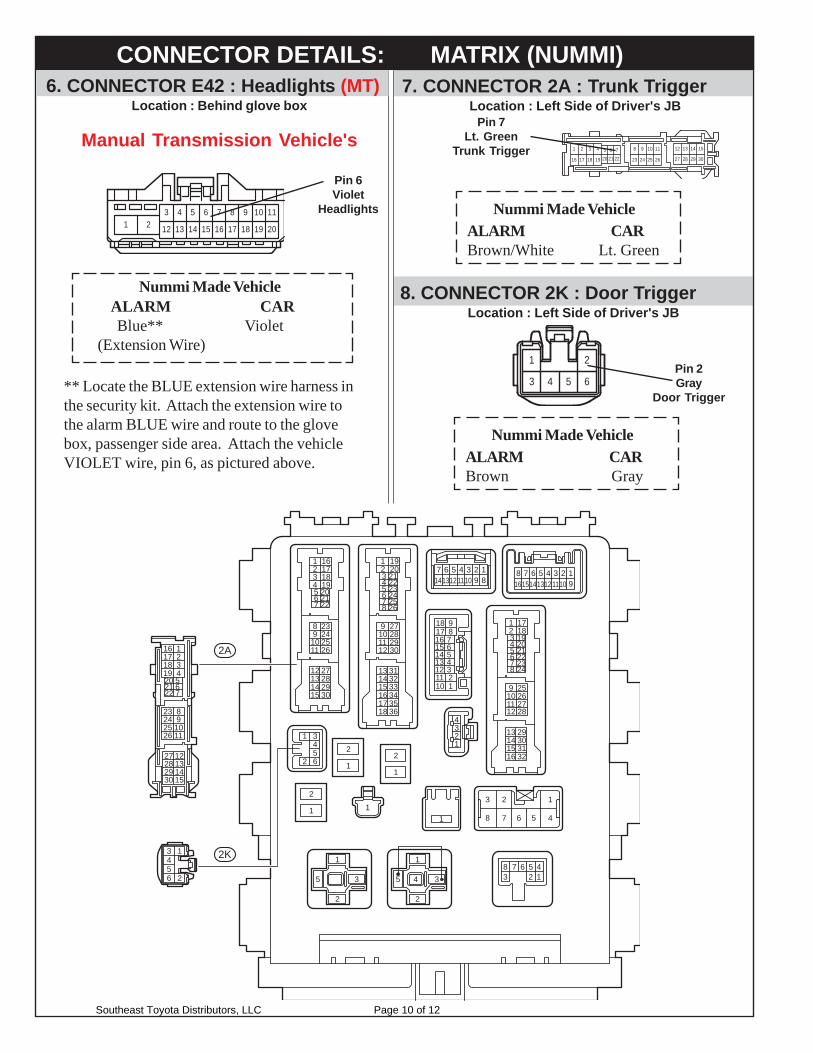
7. CONNECTOR 2A : Trunk TriggerLocation : Left Side of Driver's JB
Pin 7Lt. Green
Trunk Trigger
ALARM CARBrown/White Lt. Green
Nummi Made Vehicle
2625
11109
24
8
23 30292827
15141312
2120191817
61 5
16
432
22
7
CONNECTOR DETAILS: MATRIX (NUMMI)
8. CONNECTOR 2K : Door TriggerLocation : Left Side of Driver's JB
Pin 2Gray
Door Trigger
1 2
3 4 5 6
ALARM CARBrown Gray
Nummi Made Vehicle
6. CONNECTOR E42 : Headlights (MT)Location : Behind glove box
Manual Transmission Vehicle's
Pin 6Violet
Headlights
ALARM CAR Blue** Violet(Extension Wire)
Nummi Made Vehicle
** Locate the BLUE extension wire harness inthe security kit. Attach the extension wire tothe alarm BLUE wire and route to the glovebox, passenger side area. Attach the vehicleVIOLET wire, pin 6, as pictured above.
1 23 4 5 6 7 8 9 10 11
12 13 14 15 16 17 18 19 20
Southeast Toyota Distributors, LLC Page 10 of 12
1. Sit in the driver's seat, insert the ignition key andturn to the ON position.
2. Press the valet control switch and verify that theLED light responds. Light should go ON and OFFwith actuation of the valet control switch.
3. With the LED indicator light ON, ignition OFF andkey removed, the security system is in the valetmode and the alarm should not arm. Press the"LOCK" button, the parking lights will flash once,all doors will lock, headlights come on for 20seconds. Press the "UNLOCK" button, theparking lights will flash twice, driver's door onlywill unlock, headlights come on for 20 seconds.
4. Ignition key ON, LED light OFF, ignition key OFF.
1. Rearm the security system by pressing the "LOCK"button. Open any door or hatch. The systemshould simultaneously sound the horn and flashthe parking lights.
2. Disarm the security system by pressing the"UNLOCK" button. The system should sound (4)chirps of the horn, the parking lights should flash(4) times, indicating vehicle intrusion.
3. The LED should indicate the point of intrusionafter disarming the system. Observe the LED for1, 2, or 3 flashes. Compare your observations tothe following.
1. Press the "LOCK" button to arm the system. Usethe key to unlock and open the driver's door. Thealarm will sound. Enter the vehicle, insert theignition key and turn to the on position. Press thevalet control switch once, the alarm shoulddeactivate and the vehicle should now start.
1. Set in the driver's seat with all the doors closed.Press the "LOCK" button to arm the system. Insertthe ignition key and turn to the start position. Thestarter should not crank the engine. Press the"UNLOCK" button to disarm the system. Turn tothe start position. The starter should crank theengine. Exit vehicle.
1. Press the "LOCK" button, the system should armand lock all doors.
2. Press the "UNLOCK" button, the system willalso disarm and unlock the driver's door.
3. Press the "UNLOCK" button a second time andall doors should unlock.
F. STARTER INTERRUPT:
G. DEFECTIVE OR LOST TRANSMITTER:
H. REMOTE TRANSMITTER OPERATION:
I. INTRUSION TEST:
END
SYSTEM AUTOMATICALLY CLEARS ALLSTORED VIOLATIONS WHEN THE IGNITIONSWITCH IS TURNED TO THE "ON" POSITION.
(1) Flash = Shock(2) Flashes = Hood(3) Flashes = Vehicle Doors
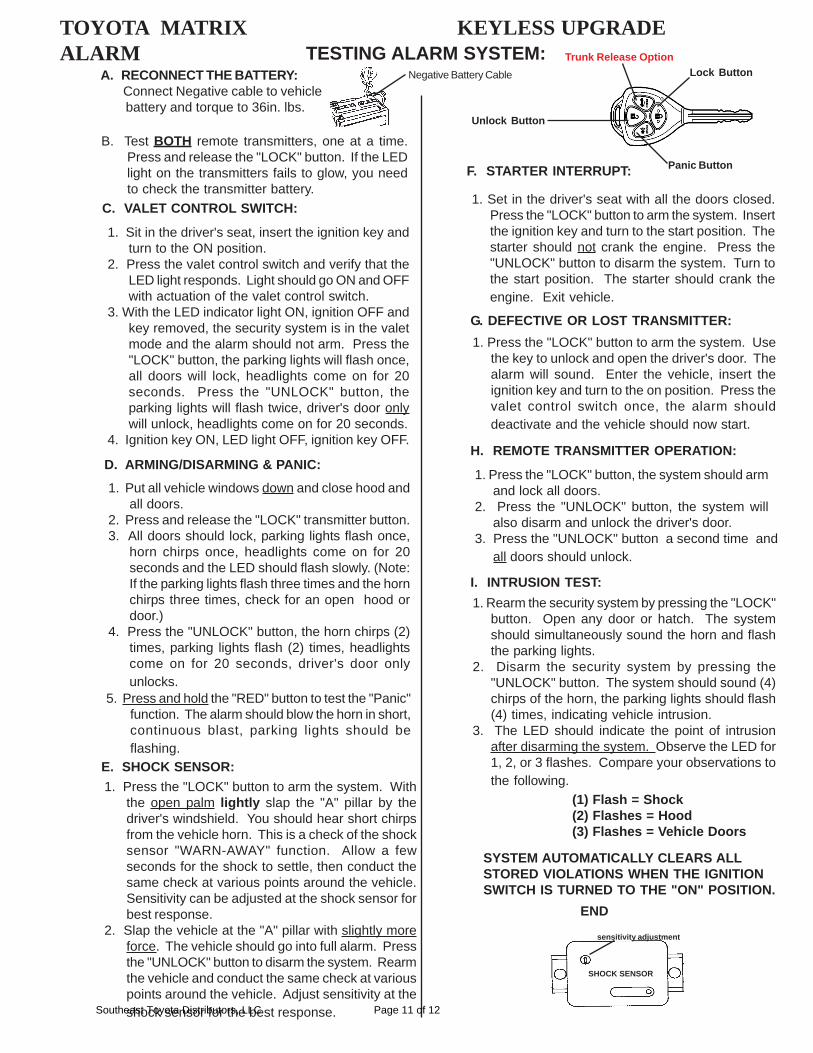
TESTING ALARM SYSTEM:
B. Test BOTH remote transmitters, one at a time.Press and release the "LOCK" button. If the LEDlight on the transmitters fails to glow, you needto check the transmitter battery.
1. Press the "LOCK" button to arm the system. Withthe open palm lightly slap the "A" pillar by thedriver's windshield. You should hear short chirpsfrom the vehicle horn. This is a check of the shocksensor "WARN-AWAY" function. Allow a fewseconds for the shock to settle, then conduct thesame check at various points around the vehicle.Sensitivity can be adjusted at the shock sensor forbest response.
2. Slap the vehicle at the "A" pillar with slightly moreforce. The vehicle should go into full alarm. Pressthe "UNLOCK" button to disarm the system. Rearmthe vehicle and conduct the same check at variouspoints around the vehicle. Adjust sensitivity at theshock sensor for the best response.
SHOCK SENSOR
sensitivity adjustment
E. SHOCK SENSOR:
C. VALET CONTROL SWITCH:
5. Press and hold the "RED" button to test the "Panic"function. The alarm should blow the horn in short,continuous blast, parking lights should beflashing.
1. Put all vehicle windows down and close hood andall doors.
2. Press and release the "LOCK" transmitter button.3. All doors should lock, parking lights flash once,
horn chirps once, headlights come on for 20seconds and the LED should flash slowly. (Note:If the parking lights flash three times and the hornchirps three times, check for an open hood ordoor.)
4. Press the "UNLOCK" button, the horn chirps (2)times, parking lights flash (2) times, headlightscome on for 20 seconds, driver's door onlyunlocks.
D. ARMING/DISARMING & PANIC:
A. RECONNECT THE BATTERY: Connect Negative cable to vehicle battery and torque to 36in. lbs.
Negative Battery Cable
TOYOTA MATRIX KEYLESS UPGRADEALARM Trunk Release Option
Lock Button
Panic Button
Unlock Button
Southeast Toyota Distributors, LLC Page 11 of 12
COMPLETING THE INSTALLATIONASSEMBLE ALL REMOVED PANELS:
1. Refer again to the vehicle repair manualand re-assemble all panels that wereremoved. Test thoroughly, all mechanicaland electrical components disconnectedand or removed from the vehicle duringthe installation of this accessory.
PREPARING VEHICLE FOR DELIVERY:
Turn the arm/disarm chirps off:1. Start with the LED/Valet switch in the off(out) position.2. Turn the ignition key to the on position.3. Turn the ignition key off, then immediatelypress and release the LED/Valet switch 3times. (You will hear 2 chirps to confirmthat the chirps were turned off.)
Place the system into Valet mode. (VPConly)1. Start with the LED/Valet switch in the off(out) position.2. Turn the ignition key to the on position.3. Press the LED/Valet switch one time. Theswitch is in the (in) position, and the red LEDlight is turned on solid, indicating that thesystem is in the Valet Mode.
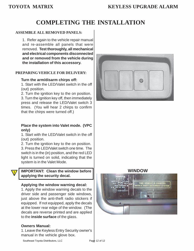
IMPORTANT: Clean the window beforeapplying the security decal.
Applying the window warning decal:1. Apply the window warning decals to thedriver side and passenger side windows,just above the anti-theft radio stickers ifequipped. If not equipped, apply the decalsat the lower rear edge of the window. (Thedecals are reverse printed and are appliedto the inside surface of the glass.
Owners Manual:1. Leave the Keyless Entry Security owner'smanual in the vehicle glove box.
WINDOW
3/8"
1"
LED
TOYOTA MATRIX KEYLESS UPGRADE ALARM
Southeast Toyota Distributors, LLC Page 12 of 12