Embed Size (px)
Citation preview
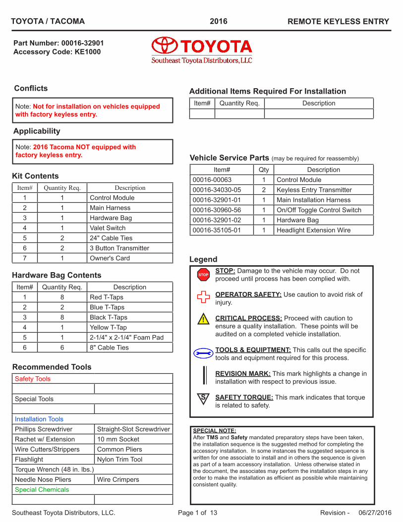
TOYOTA / TACOMA 2016 REMOTE KEYLESS ENTRY
Southeast Toyota Distributors, LLC. Page 1 of 13 Revision - 06/27/2016
Conflicts
Note: Not for installation on vehicles equipped with factory keyless entry.
Additional Items Required For Installation
Recommended Tools
Kit Contents
Legend
Hardware Bag Contents
Vehicle Service Parts (may be required for reassembly)
STOP: Damage to the vehicle may occur. Do not proceed until process has been complied with.
OPERATOR SAFETY: Use caution to avoid risk of injury.
CRITICAL PROCESS: Proceed with caution to ensure a quality installation. These points will be audited on a completed vehicle installation.
TOOLS & EQUIPTMENT: This calls out the specific tools and equipment required for this process.
REVISION MARK: This mark highlights a change in installation with respect to previous issue.
SAFETY TORQUE: This mark indicates that torque is related to safety.
Item# Quantity Req. Description1 1 Control Module2 1 Main Harness3 1 Hardware Bag4 1 Valet Switch5 2 24" Cable Ties6 2 3 Button Transmitter7 1 Owner's Card
Item# Quantity Req. Description1 8 Red T-Taps2 2 Blue T-Taps3 8 Black T-Taps4 1 Yellow T-Tap5 1 2-1/4" x 2-1/4" Foam Pad6 6 8" Cable Ties
Item# Quantity Req. Description
Safety Tools
Special Tools
Installation ToolsPhillips Screwdriver Straight-Slot ScrewdriverRachet w/ Extension 10 mm SocketWire Cutters/Strippers Common PliersFlashlight Nylon Trim ToolTorque Wrench (48 in. lbs.)Needle Nose Pliers Wire CrimpersSpecial Chemicals
Item# Qty Description00016-00063 1 Control Module00016-34030-05 2 Keyless Entry Transmitter00016-32901-01 1 Main Installation Harness00016-30960-56 1 On/Off Toggle Control Switch00016-32901-02 1 Hardware Bag00016-35105-01 1 Headlight Extension Wire
SPECIAL NOTE:After TMS and Safety mandated preparatory steps have been taken, the installation sequence is the suggested method for completing the accessory installation. In some instances the suggested sequence is written for one associate to install and in others the sequence is given as part of a team accessory installation. Unless otherwise stated in the document, the associates may perform the installation steps in any order to make the installation as efficient as possible while maintaining consistent quality.
Part Number: 00016-32901 Accessory Code: KE1000
S
!
STOP
Applicability
Note: 2016 Tacoma NOT equipped with factory keyless entry.
TOYOTA / TACOMA 2016 REMOTE KEYLESS ENTRY
Southeast Toyota Distributors, LLC. Page 2 of 13 Revision - 06/27/2016
A. Pre-Installation Precaution
1. Use Seat and Floor protectors to avoid damage to sur-faces.
2. Please review and familiarize yourself with this documentand refer to TIS before installation to check for updates to any installation procedures or techniques included in this document.
B. Battery DisconnectCAUTION:
• Certain systems need to be initialized after disconnect-ing and reconnecting the cable to the negative (-) batteryterminal.
• Before starting the engine, make sure that the groundpoint is installed to the body with the bolts.
• After the ignition switch is turned off, the navigation re-ceiver assembly records various types of memory andsettings. As a result, after turning the ignition switch off,make sure to wait at least 60 seconds before disconnect-ing the cable from the negative (-) battery terminal. (forNavigation System)
• After the ignition switch is turned off, the radio and displayreceiver assembly records various types of memory andsettings. As a result, after turning the ignition switch off,make sure to wait at least 80 seconds before disconnect-ing the cable from the negative (-) battery terminal. (forAudio and Visual System)
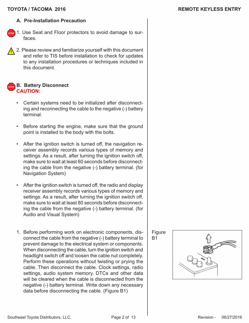
1. Before performing work on electronic components, dis-connect the cable from the negative (-) battery terminal toprevent damage to the electrical system or components.When disconnecting the cable, turn the ignition switch andheadlight switch off and loosen the cable nut completely.Perform these operations without twisting or prying thecable. Then disconnect the cable. Clock settings, radiosettings, audio system memory, DTCs and other datawill be cleared when the cable is disconnected from thenegative (-) battery terminal. Write down any necessarydata before disconnecting the cable. (Figure B1)
FigureB1
STOP
STOP
!
TOYOTA / TACOMA 2016 REMOTE KEYLESS ENTRY
Southeast Toyota Distributors, LLC. Page 3 of 13 Revision - 06/27/2016
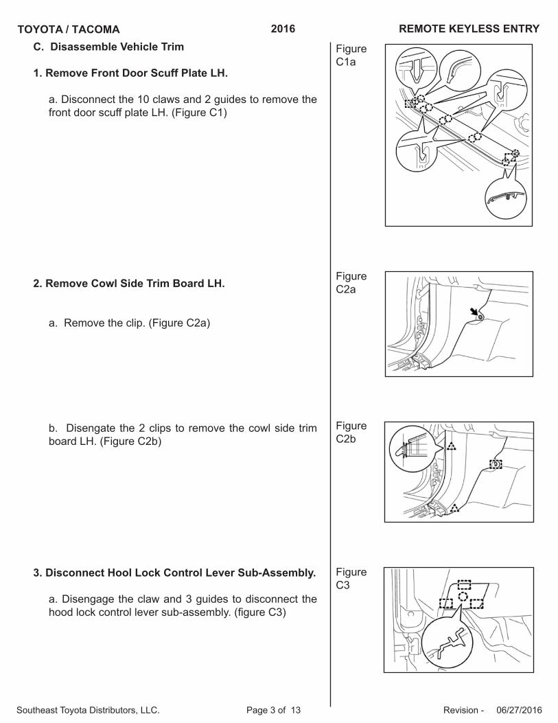
C. Disassemble Vehicle Trim
1. Remove Front Door Scuff Plate LH.
a. Disconnect the 10 claws and 2 guides to remove thefront door scuff plate LH. (Figure C1)
2. Remove Cowl Side Trim Board LH.
a. Remove the clip. (Figure C2a)
b. Disengate the 2 clips to remove the cowl side trimboard LH. (Figure C2b)
3. Disconnect Hool Lock Control Lever Sub-Assembly.
a. Disengage the claw and 3 guides to disconnect thehood lock control lever sub-assembly. (figure C3)
FigureC1a
FigureC2a
FigureC2b
FigureC3
TOYOTA / TACOMA 2016 REMOTE KEYLESS ENTRY
Southeast Toyota Distributors, LLC. Page 4 of 13 Revision - 06/27/2016
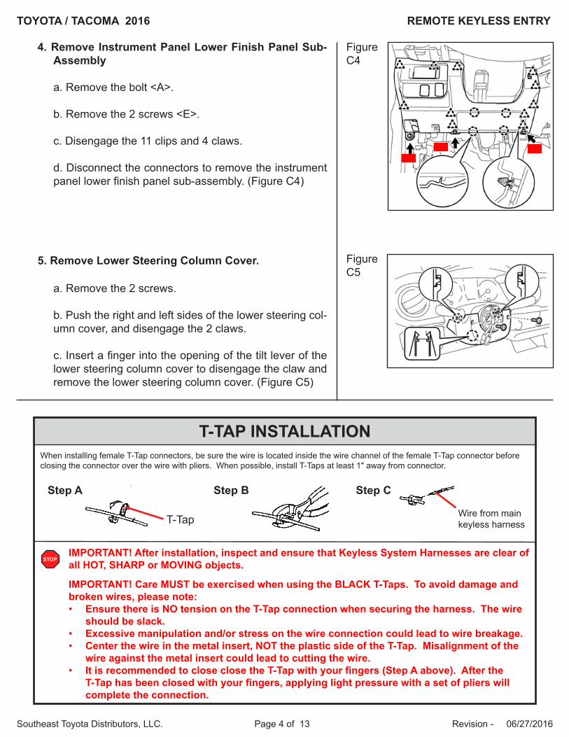
4. Remove Instrument Panel Lower Finish Panel Sub-Assembly
a. Remove the bolt <A>.
b. Remove the 2 screws <E>.
c. Disengage the 11 clips and 4 claws.
d. Disconnect the connectors to remove the instrumentpanel lower finish panel sub-assembly. (Figure C4)
5. Remove Lower Steering Column Cover.
a. Remove the 2 screws.
b. Push the right and left sides of the lower steering col-umn cover, and disengage the 2 claws.
c. Insert a finger into the opening of the tilt lever of thelower steering column cover to disengage the claw and remove the lower steering column cover. (Figure C5)
Figure C4
Figure C5
T-TAP INSTALLATIONWhen installing female T-Tap connectors, be sure the wire is located inside the wire channel of the female T-Tap connector before closing the connector over the wire with pliers. When possible, install T-Taps at least 1" away from connector.
Step A Step B Step C
Wire from main keyless harnessT-Tap
IMPORTANT! After installation, inspect and ensure that Keyless System Harnesses are clear of all HOT, SHARP or MOVING objects.
IMPORTANT! Care MUST be exercised when using the BLACK T-Taps. To avoid damage and broken wires, please note:• Ensure there is NO tension on the T-Tap connection when securing the harness. The wire
should be slack. • Excessive manipulation and/or stress on the wire connection could lead to wire breakage.• Center the wire in the metal insert, NOT the plastic side of the T-Tap. Misalignment of the
wire against the metal insert could lead to cutting the wire.• It is recommended to close close the T-Tap with your fingers (Step A above). After the
T-Tap has been closed with your fingers, applying light pressure with a set of pliers willcomplete the connection.
STOP
TOYOTA / TACOMA 2016 REMOTE KEYLESS ENTRY
Southeast Toyota Distributors, LLC. Page 5 of 13 Revision - 06/27/2016
WIR
ING
DIA
GR
AM
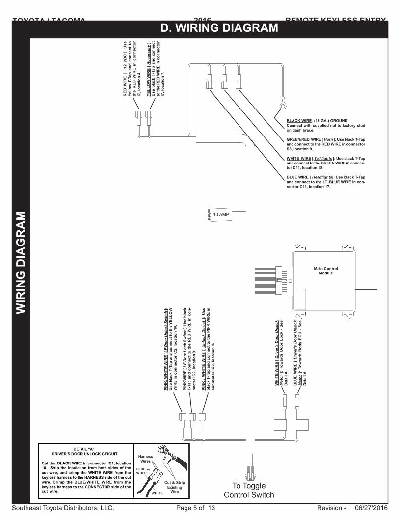
D. WIRING DIAGRAM
PIN
K / W
HIT
E W
IRE
[ LF
Doo
r Unl
ock
Switc
h ]:
Use
bla
ck T
-Tap
and
con
nect
to th
e YE
LLO
W
WIR
E in
con
nect
or IC
2, lo
catio
n 10
.
PIN
K W
IRE
[ LF
Doo
r Loc
k Sw
itch
]: U
se b
lack
T-
Tap
and
conn
ect t
o th
e R
ED W
IRE
in c
on-
nect
or IC
2, lo
catio
n 9.
PIN
K /
WH
ITE
WIR
E [
Unl
ock
Det
ect
]: U
se
blac
k T-
Tap
and
conn
ect t
o th
e PI
NK
WIR
E in
co
nnec
tor I
C2,
loca
tion
4.
Main Control Module
10 AMP
RED
WIR
E [
+12
VDC
]:
Use
Ye
llow
T-T
ap a
nd c
onne
ct t
o th
e R
ED W
IRE
in c
onne
ctor
I7
, loc
atio
n 4.
YELL
OW
WIR
E [ A
cces
sory
]:
Use
bla
ck T
-Tap
and
con
nect
to
the
RED
WIR
E in
con
nect
or
I7, l
ocat
ion
7.
BLACK WIRE- (18 GA.) GROUND:Connect with supplied nut to factory stud on dash brace.
GREEN/RED WIRE [ Horn ]: Use black T-Tap and connect to the RED WIRE in connector S8, location 9.
WHITE WIRE [ Tail lights ]: Use black T-Tap and connect to the GREEN WIRE in connec-tor C11, location 18.
BLUE WIRE [ Headlights]: Use black T-Tap and connect to the LT. BLUE WIRE in con-nector C11, location 17.
WH
ITE
WIR
E [ D
river
's D
oor U
nloc
k M
otor
]:
Tow
ards
Doo
r Lo
ck -
See
D
etai
l A
BLU
E W
IRE
[ Driv
er's
Doo
r U
nloc
k M
otor
]:
Tow
ards
Bod
y EC
U -
See
D
etai
l A
DETAIL "A" DRIVER'S DOOR UNLOCK CIRCUIT
Cut the BLACK WIRE in connector IC1, location10. Strip the insulation from both sides of thecut wire, and crimp the WHITE WIRE from thekeyless harness to the HARNESS side of the cutwire. Crimp the BLUE/WHITE WIRE from thekeyless harness to the CONNECTOR side of thecut wire.
HarnessWires
BLUE w/WHITE
Cut & StripExisting
WireWHITE
To Toggle Control Switch
TOYOTA / TACOMA 2016 REMOTE KEYLESS ENTRY
Southeast Toyota Distributors, LLC. Page 6 of 13 Revision - 06/27/2016
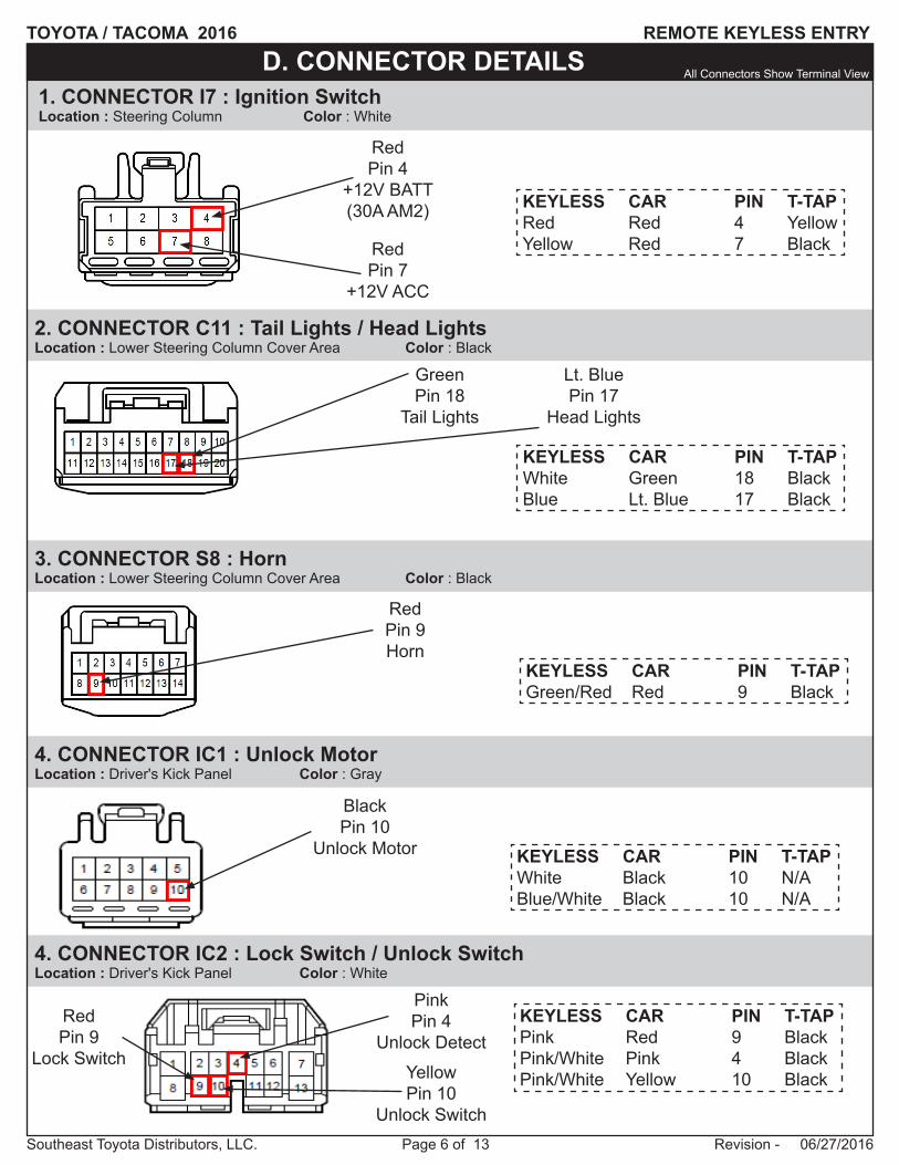
D. CONNECTOR DETAILS
3. CONNECTOR S8 : HornLocation : Lower Steering Column Cover Area Color : Black
1. CONNECTOR I7 : Ignition SwitchLocation : Steering Column Color : White
2. CONNECTOR C11 : Tail Lights / Head LightsLocation : Lower Steering Column Cover Area Color : Black
RedPin 4
+12V BATT(30A AM2)
RedPin 7
+12V ACC
RedPin 9Horn
GreenPin 18
Tail Lights
KEYLESS CAR PIN T-TAP Red Red 4 YellowYellow Red 7 Black
KEYLESS CAR PIN T-TAP Green/Red Red 9 Black
KEYLESS CAR PIN T-TAP White Green 18 BlackBlue Lt. Blue 17 Black
Lt. BluePin 17
Head Lights
All Connectors Show Terminal View
4. CONNECTOR IC1 : Unlock MotorLocation : Driver's Kick Panel Color : Gray
BlackPin 10
Unlock Motor KEYLESS CAR PIN T-TAP White Black 10 N/ABlue/White Black 10 N/A
4. CONNECTOR IC2 : Lock Switch / Unlock SwitchLocation : Driver's Kick Panel Color : White
KEYLESS CAR PIN T-TAP Pink Red 9 BlackPink/White Pink 4 BlackPink/White Yellow 10 Black
RedPin 9
Lock SwitchYellowPin 10
Unlock Switch
PinkPin 4
Unlock Detect
TOYOTA / TACOMA 2016 REMOTE KEYLESS ENTRY
Southeast Toyota Distributors, LLC. Page 7 of 13 Revision - 06/27/2016
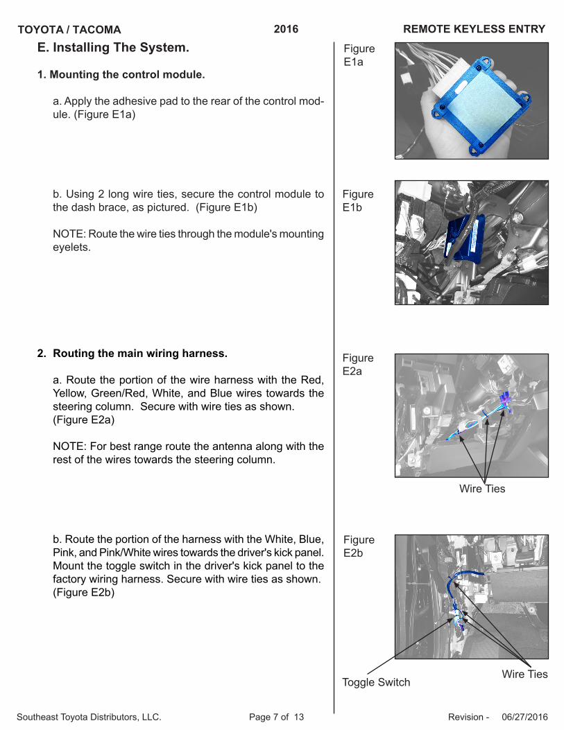
E. Installing The System.
1. Mounting the control module.
a. Apply the adhesive pad to the rear of the control mod-ule. (Figure E1a)
b. Using 2 long wire ties, secure the control module tothe dash brace, as pictured. (Figure E1b)
NOTE: Route the wire ties through the module's mounting eyelets.
2. Routing the main wiring harness.
a. Route the portion of the wire harness with the Red,Yellow, Green/Red, White, and Blue wires towards the steering column. Secure with wire ties as shown. (Figure E2a)
NOTE: For best range route the antenna along with the rest of the wires towards the steering column.
b. Route the portion of the harness with the White, Blue,Pink, and Pink/White wires towards the driver's kick panel. Mount the toggle switch in the driver's kick panel to the factory wiring harness. Secure with wire ties as shown. (Figure E2b)
FigureE1a
FigureE1b
FigureE2a
FigureE2b
Wire Ties
Wire TiesToggle Switch
TOYOTA / TACOMA 2016 REMOTE KEYLESS ENTRY
Southeast Toyota Distributors, LLC. Page 8 of 13 Revision - 06/27/2016
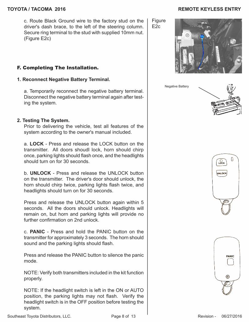
c. Route Black Ground wire to the factory stud on thedriver's dash brace, to the left of the steering column. Secure ring terminal to the stud with supplied 10mm nut.(Figure E2c)
F. Completing The Installation.
1. Reconnect Negative Battery Terminal.
a. Temporarily reconnect the negative battery terminal.Disconnect the negative battery terminal again after test-ing the system.
2. Testing The System.Prior to delivering the vehicle, test all features of the system according to the owner's manual included.
a. LOCK - Press and release the LOCK button on thetransmitter. All doors shoudl lock, horn should chirp once, parking lights should flash once, and the headlights should turn on for 30 seconds.
b. UNLOCK - Press and release the UNLOCK buttonon the transmitter. The driver's door should unlock, the horn should chirp twice, parking lights flash twice, and headlights should turn on for 30 seconds.
Press and release the UNLOCK button again within 5 seconds. All the doors should unlock. Headlights will remain on, but horn and parking lights will provide no further confirmation on 2nd unlock.
c. PANIC - Press and hold the PANIC button on thetransmitter for approximately 3 seconds. The horn should sound and the parking lights should flash.
Press and release the PANIC button to silence the panic mode.
NOTE: Verify both transmitters included in the kit function properly.
NOTE: If the headlight switch is left in the ON or AUTO position, the parking lights may not flash. Verify the headlight switch is in the OFF position before testing the system.
FigureE2c
Negative Battery
TOYOTA / TACOMA 2016 REMOTE KEYLESS ENTRY
Southeast Toyota Distributors, LLC. Page 9 of 13 Revision - 06/27/2016
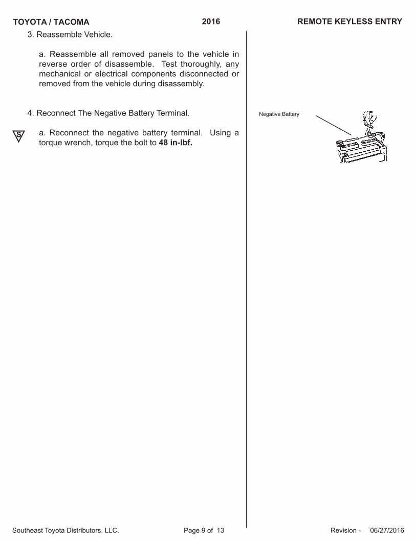
3. Reassemble Vehicle.
a. Reassemble all removed panels to the vehicle inreverse order of disassemble. Test thoroughly, any mechanical or electrical components disconnected or removed from the vehicle during disassembly.
4. Reconnect The Negative Battery Terminal.
a. Reconnect the negative battery terminal. Using atorque wrench, torque the bolt to 48 in-lbf.
S
Negative Battery

TOYOTA / TACOMA 2016 REMOTE KEYLESS ENTRY
Southeast Toyota Distributors, LLC. Page 10 of 13 Revision - 06/27/2016
PROGRAMMING NEW or REPLACEMENT TRANSMITTERS TO THE SECURITY MODULE:
The programming mode will automatically terminate after 30 seconds of inactivity. This will be confirmed by the horn sounding a SHORT-SHORT-LONG pattern. If this happens, start over at step 1 to program transmitters.
STEP 2
IMPORTANT NOTE : Once you enter the programming mode, if 30 seconds elapse with no activity on the system, the programming mode will be terminated. If this happens, simply start over.
STEP 1
Turn the vehicle’s ignition key ON then OFF 7 times at 1 second intervals.....
....Ending in the OFF position.
The vehicle will respond by sounding the horn in a SHORT-LONG pattern to confirm you have entered programming mode.
To get started, disarm the mod-ule by first locating the silver toggle switch in the driver’s kick panel.
1. Insert the key into the ignitionkey cylinder and turn to the ON position
3. Flip the toggle switch ON,then OFF.
4. Turn the ignition key to theOFF position
STEP 3Press the Lock button on the transmitter. The horn will chirp to confirm it has learned the transmitter.
STEP 4Repeat Step 3 for all transmitters that you need to program to operate the vehicle.
(Maximum of 4 transmitters per vehicle)
STEP 5When all transmitters have been programmed, turn the ignition key ON then OFF to exit the program mode.
The vehicle will respond by sounding the horn in a SHORT-SHORT-LONG pat-tern to confirm programming mode has been termindated.
1 Second
ON
ON
OFF
OFF
TOYOTA / TACOMA 2016 REMOTE KEYLESS ENTRY
Southeast Toyota Distributors, LLC. Page 11 of 13 Revision - 06/27/2016
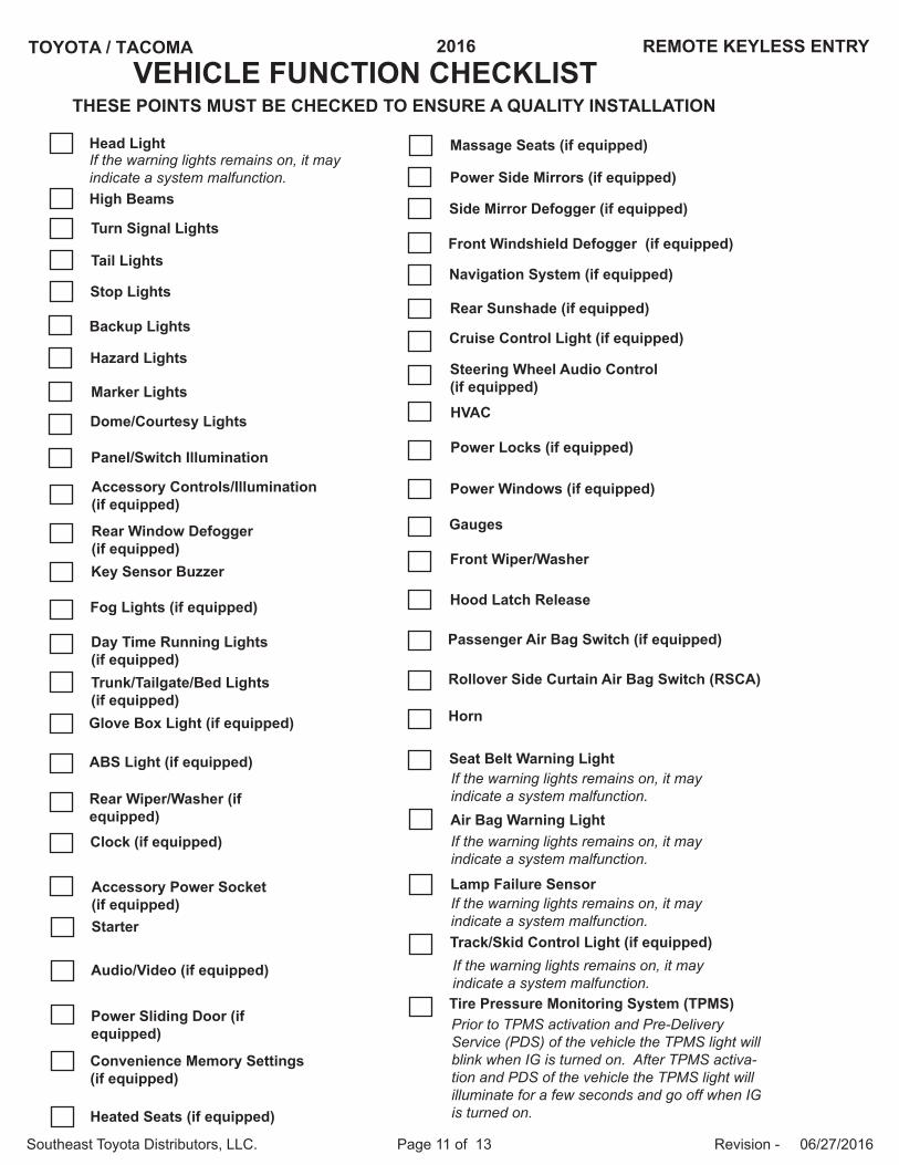
VEHICLE FUNCTION CHECKLISTTHESE POINTS MUST BE CHECKED TO ENSURE A QUALITY INSTALLATION
Head Light
High Beams
Turn Signal Lights
Tail Lights
Stop Lights
Backup Lights
Hazard Lights
Marker Lights
Dome/Courtesy Lights
Panel/Switch Illumination
Accessory Controls/Illumination (if equipped)
Rear Window Defogger (if equipped)Key Sensor Buzzer
Fog Lights (if equipped)
Day Time Running Lights (if equipped)Trunk/Tailgate/Bed Lights (if equipped)Glove Box Light (if equipped)
ABS Light (if equipped)
Rear Wiper/Washer (if equipped)Clock (if equipped)
Accessory Power Socket (if equipped)Starter
Audio/Video (if equipped)
Power Sliding Door (if equipped)
If the warning lights remains on, it may indicate a system malfunction.
Convenience Memory Settings (if equipped)
Heated Seats (if equipped)
Massage Seats (if equipped)
Power Side Mirrors (if equipped)
Side Mirror Defogger (if equipped)
Front Windshield Defogger (if equipped)
Navigation System (if equipped)
Rear Sunshade (if equipped)
Cruise Control Light (if equipped)
Steering Wheel Audio Control (if equipped)HVAC
Power Locks (if equipped)
Power Windows (if equipped)
Gauges
Front Wiper/Washer
Hood Latch Release
Passenger Air Bag Switch (if equipped)
Rollover Side Curtain Air Bag Switch (RSCA)
Horn
Seat Belt Warning Light
Air Bag Warning Light
Lamp Failure Sensor
Track/Skid Control Light (if equipped)
If the warning lights remains on, it may indicate a system malfunction.
If the warning lights remains on, it may indicate a system malfunction.
If the warning lights remains on, it may indicate a system malfunction.
If the warning lights remains on, it may indicate a system malfunction.Tire Pressure Monitoring System (TPMS)Prior to TPMS activation and Pre-Delivery Service (PDS) of the vehicle the TPMS light will blink when IG is turned on. After TPMS activa-tion and PDS of the vehicle the TPMS light will illuminate for a few seconds and go off when IG is turned on.
TOYOTA / TACOMA 2016 REMOTE KEYLESS ENTRY
Southeast Toyota Distributors, LLC. Page 12 of 13 Revision - 06/27/2016
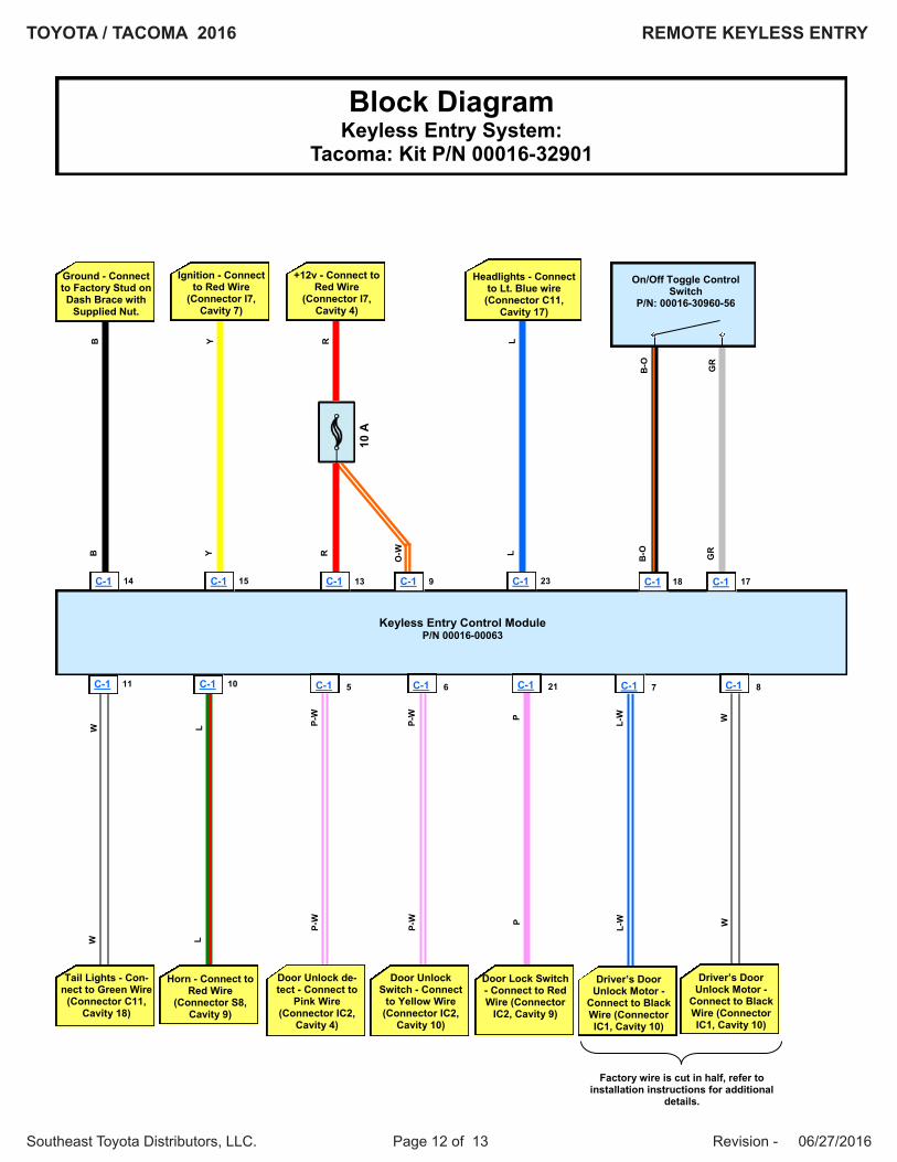
Block Diagram Keyless Entry System:
Tacoma: Kit P/N 00016-32901
Keyless Entry Control Module P/N 00016-00063
P-W
P-
W
C-1 14
B
B
Ground - Connect to Factory Stud on Dash Brace with
Supplied Nut.
C-1 15
Y Y
Ignition - Connect to Red Wire
(Connector I7, Cavity 7)
C-1
R
R
+12v - Connect to Red Wire
(Connector I7, Cavity 4)
C-1 23
L L
Headlights - Connect to Lt. Blue wire (Connector C11,
Cavity 17)
C-1 11
W
W
13
Tail Lights - Con-nect to Green Wire
(Connector C11, Cavity 18)
L
C-1 10
L
Horn - Connect to Red Wire
(Connector S8, Cavity 9)
C-1 5
P-W
P-
W
C-1 6
Door Unlock de-tect - Connect to
Pink Wire (Connector IC2,
Cavity 4)
Door Unlock Switch - Connect
to Yellow Wire (Connector IC2,
Cavity 10)
P P
C-1 21
Door Lock Switch - Connect to Red Wire (Connector
IC2, Cavity 9)
L-W
L-
W
C-1 7
Driver’s Door Unlock Motor -
Connect to Black Wire (Connector IC1, Cavity 10)
W
W
C-1 8
10 A
C-1
O-W
9
Driver’s Door Unlock Motor -
Connect to Black Wire (Connector IC1, Cavity 10)
Factory wire is cut in half, refer to installation instructions for additional
details.
C-1 18
B-O
B
-O
C-1 17
GR
G
R
On/Off Toggle Control Switch
P/N: 00016-30960-56
TOYOTA / TACOMA 2016 REMOTE KEYLESS ENTRY
Southeast Toyota Distributors, LLC. Page 13 of 13 Revision - 06/27/2016
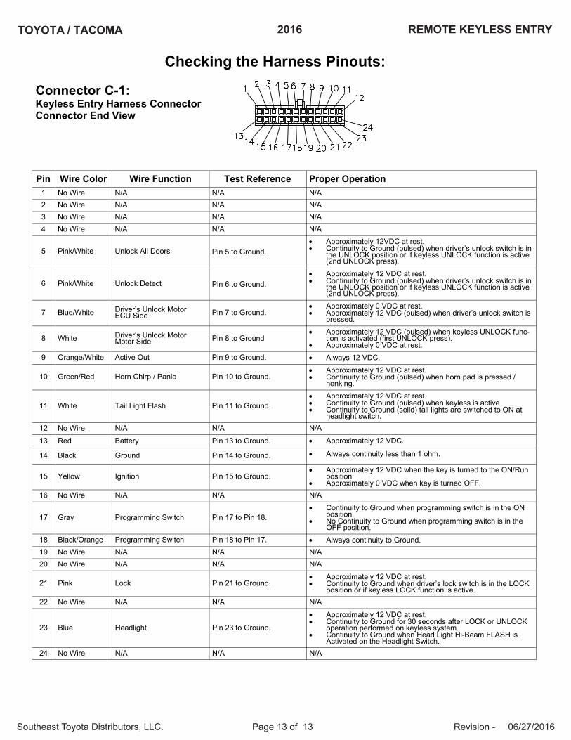
Connector C-1:Keyless Entry Harness ConnectorConnector End View
Pin Wire Color Test Reference Proper OperationWire Function1 No Wire N/A N/AN/A2 No Wire N/A N/AN/A3 No Wire N/A N/AN/A4 No Wire N/A N/AN/A
5 Pink/White Pin 5 to Ground. Approximately 12VDC at rest. Continuity to Ground (pulsed) when driver’s unlock switch is in
the UNLOCK position or if keyless UNLOCK function is active(2nd UNLOCK press).
Unlock All Doors
6 Pink/White Pin 6 to Ground. Approximately 12 VDC at rest. Continuity to Ground (pulsed) when driver’s unlock switch is in
the UNLOCK position or if keyless UNLOCK function is active(2nd UNLOCK press).
Unlock Detect
7 Blue/White Pin 7 to Ground. Approximately 0 VDC at rest. Approximately 12 VDC (pulsed) when driver’s unlock switch is
pressed.Driver’s Unlock MotorECU Side
8 White Pin 8 to Ground Approximately 12 VDC (pulsed) when keyless UNLOCK func-
tion is activated (first UNLOCK press). Approximately 0 VDC at rest.
Driver’s Unlock MotorMotor Side
9 Orange/White Pin 9 to Ground. Always 12 VDC.Active Out
10 Green/Red Pin 10 to Ground. Approximately 12 VDC at rest. Continuity to Ground (pulsed) when horn pad is pressed /
honking.Horn Chirp / Panic
11 White Pin 11 to Ground. Approximately 12 VDC at rest. Continuity to Ground (pulsed) when keyless is active Continuity to Ground (solid) tail lights are switched to ON at
headlight switch.Tail Light Flash
12 No Wire N/A N/AN/A
13 Red Pin 13 to Ground. Approximately 12 VDC.Battery
14 Black Pin 14 to Ground. Always continuity less than 1 ohm.Ground
15 Yellow Pin 15 to Ground. Approximately 12 VDC when the key is turned to the ON/Run
position. Approximately 0 VDC when key is turned OFF.
Ignition
16 No Wire N/A N/AN/A
17 Gray Pin 17 to Pin 18. Continuity to Ground when programming switch is in the ON
position. No Continuity to Ground when programming switch is in the
OFF position.Programming Switch
18 Black/Orange Pin 18 to Pin 17. Always continuity to Ground.Programming Switch19 No Wire N/A N/AN/A20 No Wire N/A N/AN/A
21 Pink Pin 21 to Ground. Approximately 12 VDC at rest. Continuity to Ground when driver’s lock switch is in the LOCK
position or if keyless LOCK function is active.Lock
22 No Wire N/A N/AN/A
23 Blue Pin 23 to Ground.
Approximately 12 VDC at rest. Continuity to Ground for 30 seconds after LOCK or UNLOCK
operation performed on keyless system. Continuity to Ground when Head Light Hi-Beam FLASH is
Activated on the Headlight Switch.
Headlight
24 No Wire N/A N/AN/A
Checking the Harness Pinouts:


![51300-00016-SG[1] co2](https://img.pdfslide.us/doc/110x75/577ce7351a28abf103949862/51300-00016-sg1-co2.jpg)