Embed Size (px)
Citation preview

REPORT NUMBER: 208-MGA-2006-002
VEHICLE SAFETY COMPLIANCE TESTING FOR
FMVSS 208, OCCUPANT CRASH PROTECTION FMVSS 212, WINDSHIELD MOUNTING
FMVSS 219, WINSHIELD INTRUSION (PARTIAL) FMVSS 301, FUEL SYSTEM INTEGRITY
New United Motor Manufacturing Inc. 2006 Toyota Corolla Passenger Car
NHTSA No.: C65103
PREPARED BY: MGA RESEARCH CORPORATION
5000 WARREN ROAD BURLINGTON, WI 53105
Test Date: December 14, 2005
Final Report Date: March 17, 2006
FINAL REPORT
PREPARED FOR: U.S. DEPARTMENT OF TRANSPORTATION
NATIONAL HIGHWAY TRAFFIC SAFETY ADMINISTRATION OFFICE OF ENFORCEMENT
OFFICE OF VEHICLE SAFETY COMPLIANCE MAIL CODE: NVS-220
400 SEVENTH STREET, SW, ROOM 6115 WASHINGTON, D.C. 20590

ii
This final test report was prepared for the U.S. Department of Transportation,
National Highway Traffic Safety Administration, in response to Contract Number DTNH22-03-D-11002.
This publication is distributed by the U.S. Department of Transportation, National
Highway Traffic Safety Administration, in the interest of information exchange. The opinions, findings and conclusions expressed in this publication are those of the author(s) and not necessarily those of the Department of Transportation or the National Highway Traffic Safety Administration. The United States Government assumes no liability for its contents or use thereof. If trade or manufacturers' names or products are mentioned it is only because they are considered essential to the object of the publication and should not be construed as an endorsement. The United States Government does not endorse products or manufacturers. Prepared by: _____________________________ Date: March 17, 2006
Jeff Lewandowski, Project Engineer Reviewed by: _____________________________ Date: March 17, 2006
David Winkelbauer, Facility Director FINAL REPORT ACCEPTED BY OVSC: Accepted By: __ _________________________
Acceptance Date: March 17, 2006__________________

iii
Technical Report Documentation Page
1. Report No. 208-MGA-2006-002
2. Government Accession No.
3. Recipient's Catalog No.
5. Report Date March 17, 2006
4. Title and Subtitle Final Report of FMVSS 208 Compliance Testing of a 2006 Toyota Corolla NHTSA No.: C65103
6. Performing Organization Code MGA
7. Author(s) Jeff Lewandowski, Project Engineer
8. Performing Organization Report No. 208-MGA-2006-002 10. Work Unit No.
9. Performing Organization Name and Address MGA Research Corporation 5000 Warren Road Burlington, WI 53105 11. Contract or Grant No.
DTNH22-03-D-11002 13. Type of Report and Period Covered 12/14/05 - 03/17/06
12. Sponsoring Agency Name and Address U.S. Department of Transportation National Highway Traffic Safety Administration Office of Enforcement Office of Vehicle Safety Compliance 400 Seventh St., S.W., Room 6115 NVS-220 Washington, D.C. 20590
14. Sponsoring Agency Code NVS-220
15. Supplementary Notes
16. Abstract Compliance tests were conducted on the subject 2006 Toyota Corolla in accordance with the specifications of the Office of Vehicle Safety Compliance Test Procedure No. TP208-12 for the determination of FMVSS 208 compliance. Test failures identified were as follows: TEST FAILURES: None
17. Key Words Frontal Impact 40 kmph Vehicle Safety Compliance Testing FMVSS 208, “Occupant Crash Protection” FMVSS 212, “Windshield Mounting” FMVSS 219, (partial), “Windshield Zone Intrusion” FMVSS 301, “Fuel System Integrity”
18. Distribution Statement Copies of this report are available from the following: NHTSA Technical Information Services (TIS), Mail Code: NPO-230 400 Seventh Street, S.W., Room 5108 Washington, D.C. 20590 Tel. No.: (202) 366-4946
19. Security Classif. (of this report) Unclassified
20. Security Classif. (of this page) Unclassified
21. No. of Pages 161
22. Price
Form DOT F1700.7 (8-72)

iv
TABLE OF CONTENTS
Section Page No 1 Purpose of Compliance Test 1 2 Tests Performed 2 3 Injury Result Summary 4 4 Discussion of Test (if applicable) 5 5 Test Data Sheets 6 Data Sheet 1 COTR Vehicle Work Order 7 2 Report of Vehicle Condition 11 3 Certification Label and Tire Placard Information 13 14 Marking of Reference Points for Various Test Positions & Points 14 30 Vehicle Weight, Fuel Tank, and Attitude Data 21 31 Vehicle Accelerometer Locations and Measurements 25 32 Photographic Targets 28 33 Camera Locations 34 34 Dummy Positioning 36 35 Dummy Measurements 45 36 Crash Test 48 38 Accident Investigation Measurements 50 39 Windshield Mounting (FMVSS 212) 52 40 Windshield Zone Intrusion (FMVSS 219) 54 41 Fuel System Integrity (FMVSS 301) 56 Appendix A Crash Test Data A-1 B Crash Test Photographs B-1 C Instrumentation Calibration C-1 D H Point ATD Positioning CCM Data D-1 E Notice of Test Failure (If Applicable) E-1

1
SECTION 1
PURPOSE OF COMPLIANCE TEST
The tests performed are part of a program conducted for the National Highway Traffic
Safety Administration (NHTSA) by MGA Research Corporation (MGA) under Contract No.
DTNH22-03-D-11002. The purpose of this test was to determine whether the subject vehicle, a
2006 Toyota Corolla, NHTSA No. C65103, meets certain performance requirements of FMVSS
208, "Occupant Crash Protection"; FMVSS 212, "Windshield Mounting"; FMVSS 219,
"Windshield Zone Intrusion"; and FMVSS 301, "Fuel System Integrity". The compliance test
was conducted in accordance with OVSC Laboratory Test Procedure No. TP208-12 dated
January 14, 2003.

2
SECTION 2 TESTS PERFORMED
The following checked items indicate the tests that were performed:
1. Rear outboard seating position seat belts (S4.1.1.2(b) & (S4.2.4) 2. Air bag labels (S4.5.1) 3. Readiness indicator (S4.5.2) 4. Passenger air bag manual cut-off device (S4.5.4) 5. Lap belt lockability (S7.1.1.5) 6. Seat belt warning system (S7.3) 7. Seat belt contact force (S7.4.4) 8. Seat belt latch plate access (S7.4.4) 9. Seat belt retraction (S7.4.5) 10. Seat belt guides and hardware (S7.4.6) 11. Suppression tests with 12-month-old CRABI dummy (Part 572, Subpart R) 12. Suppression tests with newborn infant (Part 572, Subpart K) 13. Suppression tests with 3-year-old dummy (Part 572, Subpart P) 14. Suppression tests with 6-year-old dummy (Part 572, Subpart N)
15. Test of reactivation of the passenger air bag system with an unbelted 5th percentile female dummy
16. Low risk deployment test with 12-month-old dummy (Part 572, Subpart R) 17. Low risk deployment test with 3-year-old dummy (Part 572, Subpart P) 18. Low risk deployment test with 6-year-old dummy (Part 572, Subpart N) 19. Low risk deployment test with 5th female dummy (Part 572, Subpart O) 20. Impact Tests Frontal Oblique
Belted 50th male dummy driver and passenger (0 to 48 kmph) (S5.1.1(a))
Unbelted 50th male dummy driver and passenger (0 to 48 kmph) (S5.1.2(a)(1))
Unbelted 50th male dummy driver and passenger (32 to 40 kmph) (S5.1.2(a) (1) or S5.1.2(b))
X Frontal 0°
Belted 50th male dummy driver (0 to 48 kmph) (S5.1.1.(b)(1) or S5.1.1(a))
Belted 50th male dummy passenger (0 to 48 kmph) (S5.1.1.(b)(1) or S5.1.1(a))
Belted 5th female dummy driver (0 to 48 kmph) (S16.1(a)) Belted 5th female dummy passenger (0 to 48 kmph) (S16.1(a))
Belted 50th male dummy driver and passenger (0 to 56 kmph) (S5.1.1.(b)(2))
Unbelted 50th male dummy driver and passenger (0 to 48 kmph) (S5.1.2(a) (1))
X
Unbelted 50th male dummy driver (32 to 40 kmph) (S5.1.2.(a)(2) or S5.1.2(b))
X
Unbelted 50th male dummy passenger (32 to 40 kmph) (S5.1.2.(a)(2) or S5.1.2(b))
Test Vehicle: 2006 Toyota Corolla Test Program: FMVSS 208 Compliance
NHTSA No.: C65103 Test Date: 12/14/05

3
Unbelted 5th female dummy driver (32 to 40 kmph) (S16.1(b)) Unbelted 5th female dummy passenger (32 to 40 kmph) (S16.1(b))
40% Offset 0° Belted 5th male dummy driver and passenger (0 to 40 kmph) (S18.1)
21. Sled Test: unbelted 50th male dummy driver and passenger (S13) 22. FMVSS 204 Indicant Test
X 23. FMVSS 212 Indicant Test X 24. FMVSS 219 Indicant Test X 25. FMVSS 301 Frontal Indicant Test
For the crash tests, the vehicle was instrumented with 8 accelerometers. The accelerometer data from the vehicle and dummies were sampled at 10,000 samples per second and processed as specified in SAE J211/1 MAR95 and FMVSS 208, S4.13. The dynamic tests were recorded using high-speed film and high-speed digital video. The vehicle appears to meet all of the performance requirements to which it was tested.
4
SECTION 3 INJURY RESULT SUMMARY FOR FMVSS 208 TESTS
40 kmph Frontal Crash Impact Angle: Zero degrees Belted Dummies: ___Yes _X No Speed Range: ___ 0 to 40 kmph _X 32 to 40 kmph ___ 0 to 48 kmph ___ 0 to 56 kmph Test Speed: 39.8 kmph Test Weight: 1360.0 kg Driver Dummy: ___5th female _X 50th male Passenger Dummy: ___5th female _X 50th male
50th Percentile Male Frontal Crash Test Vehicles certified to S5.1.1(b)(1), S5.1.1(b)(2), S5.1.2(a)(2), or S5.1.2(b)
Injury Criteria Max. Allowable Injury Assessment Values Driver Passenger
HIC15 700 355 87 Nte 1.0 0.2 0.1 Ntf 1.0 0.2 0.1 Nce 1.0 0.4 0.2 Ncf 1.0 0.7 0.8 Neck Tension 4170 N 472 159 Neck Compression 4000 N 3061 2892 Chest g 60 g 40 24 Chest Displacement 63 mm 29 8 Left Femur 10,000 N 3649 4403 Right Femur 10,000 N 3466 3464
Test Vehicle: 2006 Toyota Corolla Test Program: FMVSS 208 Compliance
NHTSA No.: C65103 Test Date: 12/14/05

5
SECTION 4 DISCUSSION OF TESTS
The vehicle was tested in a 25 mph frontal impact only. FMVSS 208 Datasheets not used for this test have been removed from the report. The post test FMVSS 301 rollover was not conducted at the direction of the COTR. Driver and passenger H Point ATD positioning CCM data is provided in Appendix D.
Test Vehicle: 2006 Toyota Corolla Test Program: FMVSS 208 Compliance
NHTSA No.: C65103 Test Date: 12/14/05

6
SECTION 5 TEST DATA SHEETS
Test Vehicle: 2006 Toyota Corolla Test Program: FMVSS 208 Compliance
NHTSA No.: C65103 Test Dates: 12/14/05

7
DATA SHEET 1 COTR VEHICLE WORK ORDER
COTR Signature: Charles R. Case Test to be performed for this vehicle are checked below: 1. Rear Outboard Seating Position Seat Belts (S4.1.2(b)) & (S4.2.4) 2. Air Bag Labels (S4.5.1) 3. Readiness Indicator (S4.5.2) 4. Passenger Air Bag Manual Cut-off Device (S4.5.4) 5. Lap Belt Lockability (S7.1.1.5) 6. Seat Belt Warning System (S7.3) 7. Seat Belt Contact Force (S7.4.4) 8. Seat Belt Latch Plate Access (S7.4.4) 9. Seat Belt Retraction (S7.4.5) 10. Seat Belt Guides and Hardware (S7.4.6)
11. Suppression tests with 12-month-old CRABI dummy (Part 572, Subpart R) using the following indicated child restraints.
Section B Britax Handle with Care 191 Full Rearward Mid Position Full Forward Century Assura 4553 Full Rearward Mid Position Full Forward Century Avanta SE 41530 Full Rearward Mid Position Full Forward Century Smart Fit 4543 Full Rearward Mid Position Full Forward Cosco Arriva 02727 Full Rearward Mid Position Full Forward Cosco Opus 35 02603 Full Rearward Mid Position Full Forward Evenflo Discovery Adjust Right
212 Full Rearward Mid Position Full Forward
Evenflo First Choice 204 Full Rearward Mid Position Full Forward Evenflo On My Way Position
Right V 282 Full Rearward Mid Position Full Forward
Graco Infant 8457 Full Rearward Mid Position Full Forward Section C Britax Roundabout 161 Full Rearward Mid Position Full Forward Century Encore 4612 Full Rearward Mid Position Full Forward Century STE 1000 4416 Full Rearward Mid Position Full Forward Cosco Olympian 02803 Full Rearward Mid Position Full Forward Cosco Touriva 02519 Full Rearward Mid Position Full Forward Evenflo Horizon V 425 Full Rearward Mid Position Full Forward Evenflo Medallion 254 Full Rearward Mid Position Full Forward
12. Suppression tests with newborn infant (Part 572, Subpart K) using the following indicated child restraints.
Section A Cosco Dream Ride 02-719 Full Rearward Mid Position Full Forward
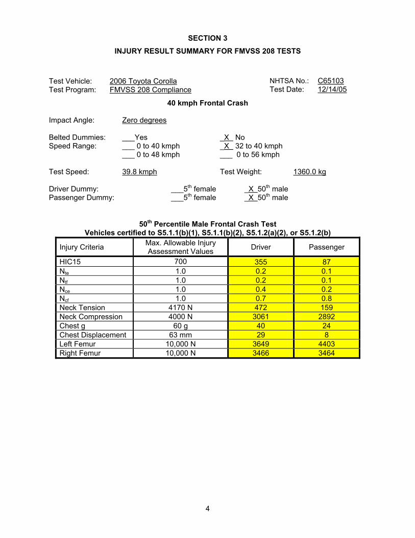
13. Suppression tests with 3-year-old dummy (Part 572, Subpart P) using the following indicated child restraints where a child restraint is required.
Test Vehicle: 2006 Toyota Corolla Test Program: FMVSS 208 Compliance
NHTSA No.: C65103 Test Date: 12/14/05
8
Section C Britax Roundabout 161 Full Rearward Mid Position Full Forward Century Encore 4612 Full Rearward Mid Position Full Forward Century STE 1000 4416 Full Rearward Mid Position Full Forward Cosco Olympian 02803 Full Rearward Mid Position Full Forward Cosco Touriva 02519 Full Rearward Mid Position Full Forward Evenflo Horizon V 425 Full Rearward Mid Position Full Forward Evenflo Medallion 254 Full Rearward Mid Position Full Forward Section D Britax Roadster 9004 Full Rearward Mid Position Full Forward Century Next Step 4920 Full Rearward Mid Position Full Forward Cosco High Back Booster
02-442 Full Rearward Mid Position Full Forward
Evenflo Right Fit 245 Full Rearward Mid Position Full Forward
14. Suppression tests with representative 3-year-old child using the following indicated child restraints where a child restraint is required. (Appendix H, Data Sheet 16H and 17H)
Section C Britax Roundabout 161 Full Rearward Mid Position Full Forward Century Encore 4612 Full Rearward Mid Position Full Forward Century STE 1000 4416 Full Rearward Mid Position Full Forward Cosco Olympian 02803 Full Rearward Mid Position Full Forward Cosco Touriva 02519 Full Rearward Mid Position Full Forward Evenflo Horizon V 425 Full Rearward Mid Position Full Forward Evenflo Medallion 254 Full Rearward Mid Position Full Forward Section D Britax Roadster 9004 Full Rearward Mid Position Full Forward Century Next Step 4920 Full Rearward Mid Position Full Forward Cosco High Back Booster
02-442 Full Rearward Mid Position Full Forward
Evenflo Right Fit 245 Full Rearward Mid Position Full Forward
15. Suppression tests with 3-year-old dummy (Part 572, Subpart P) in the following Forward, Middle, and Rearward seat track positions
Sitting on seat with back against seat back (S22.2.2.1) Sitting on seat with back against reclined seat back (S22.2.2.2) Sitting on seat with back not against seat back (S22.2.2.3) Sitting on seat edge, spine vertical, hands by the child’s side (S22.2.2.4) Standing on seat, facing forward (S22.2.2.5) Kneeling on seat facing forward (S22.2.2.6) Kneeling on seat facing rearward (S22.2.2.7) Lying on seat (S22.2.2.8) 16. Suppression tests with representative 3-year-old child in the following positions Sitting on seat with back against seat back (S22.2.2.1) Sitting on seat with back against reclined seat back (S22.2.2.2) Sitting on seat with back not against seat back (S22.2.2.3) Sitting on seat edge, spine vertical, hands by the child’s side (S22.2.2.4) Standing on seat, facing forward (S22.2.2.5) Kneeling on seat facing forward (S22.2.2.6) Kneeling on seat facing rearward (S22.2.2.7) Lying on seat (S22.2.2.8)
17. Suppression tests with 6-year-old dummy (Part 572, Subpart N) using the following indicated child restraints where a child restraint is required.

9
Section D Britax Roadster 9004 Full Rearward Mid Position Full Forward Century Next Step 4920 Full Rearward Mid Position Full Forward Cosco High Back Booster
02-442 Full Rearward Mid Position Full Forward
Evenflo Right Fit 245 Full Rearward Mid Position Full Forward
18. Suppression tests with representative 6-year-old child using the following indicated child restraints where a child restraint is required.
Section D Britax Roadster 9004 Full Rearward Mid Position Full Forward Century Next Step 4920 Full Rearward Mid Position Full Forward Cosco High Back Booster 02-442 Full Rearward Mid Position Full Forward Evenflo Right Fit 245 Full Rearward Mid Position Full Forward
19. Suppression tests with 6-year-old dummy (Part 572, Subpart N) in the following Forward, Middle, and Rearward seat track positions
Sitting on seat with back against seat back (S22.2.2.1)
Sitting on seat with back against reclined seat back (S22.2.2.2)
Sitting on seat edge, spine vertical, hands by the child’s side (S22.2.2.4)
Sitting back in the seat and leaning on the right front passenger door (S24.2.3)
20. Suppression tests with representative 6-year-old child in the following positions Sitting on seat with back against seat back (S22.2.2.1)
Sitting on seat with back against reclined seat back (S22.2.2.2)
Sitting on seat edge, spine vertical, hands by the child’s side (S22.2.2.4)
Sitting back in the seat and leaning on the right front passenger door (S24.2.3)
21. Test of Reactivation of the Passenger Air Bag System with an Unbelted 5th percentile female dummy (S20.3, 22.3, S24.3). Perform this test after the following suppression tests: After each restraint.
22. Test of Reactivation of the passenger air bag system with a representative 5th percentile female (S20.3, 22.3, S24.3). Perform this test after the following suppression tests:
23. Low risk deployment test with 12-month-old dummy (Part 572, Subpart R) using the following indicated child restraints.
Section B Britax Handle with Care 191 Full Rearward Mid Position Full Forward Century Assura 4553 Full Rearward Mid Position Full Forward Century Avanta SE 41530 Full Rearward Mid Position Full Forward Century Smart Fit 4543 Full Rearward Mid Position Full Forward Cosco Arriva 02727 Full Rearward Mid Position Full Forward Cosco Opus 35 02603 Full Rearward Mid Position Full Forward Evenflo Discovery Adjust Right
212 Full Rearward Mid Position Full Forward
Evenflo First Choice 204 Full Rearward Mid Position Full Forward Evenflo On My Way Position
Right V 282 Full Rearward Mid Position Full Forward
Graco Infant 8457 Full Rearward Mid Position Full Forward Section C Britax Roundabout 161 Full Rearward Mid Position Full Forward Century Encore 4612 Full Rearward Mid Position Full Forward Century STE 1000 4416 Full Rearward Mid Position Full Forward Cosco Olympian 02803 Full Rearward Mid Position Full Forward Cosco Touriva 02519 Full Rearward Mid Position Full Forward Evenflo Horizon V 425 Full Rearward Mid Position Full Forward Evenflo Medallion 254 Full Rearward Mid Position Full Forward

10
24. Low risk deployment test with 3-year-old dummy (Part 572, Subpart P) in the following positions
Position 1
Position 2
25. Low risk deployment test with 6-year-old dummy (Part 572, Subpart N) in the following positions
Position 1
Position 2
26. Low risk deployment test with 5th percentile female dummy (Part 572, Subpart O) in the following positions
Position 1
Position 2
X 27. Impact Tests Frontal Oblique – Test Speed: Belted 50th male dummy driver and passenger (0 to 48 kmph) (S5.1.1(a))
Unbelted 50th male dummy driver and passenger (0 to 48 kmph) (S5.1.2(a)(1))
Unbelted 50th male dummy driver and passenger (32 to 40 kmph) (S5.1.2(a) (1) or S5.1.2(b))
X Frontal 0° - Test Speed: 39.8 kmph Belted 50th male dummy driver (0 to 48 kmph) (S5.1.1.(b)(1) or S5.1.1(a))
Belted 50th male dummy passenger (0 to 48 kmph) (S5.1.1.(b)(1) or S5.1.1(a))
Belted 5th female dummy driver (0 to 48 kmph) (S16.1(a))
Belted 5th female dummy passenger (0 to 48 kmph) (S16.1(a))
Belted 50th male dummy driver and passenger (0 to 56 kmph) (S5.1.1.(b)(2))
Unbelted 50th male dummy driver and passenger (0 to 48 kmph) (S5.1.2(a) (1))
X Unbelted 50th male dummy driver (32 to 40 kmph) (S5.1.2.(a)(2) or S5.1.2(b))
X Unbelted 50th male dummy passenger (32 to 40 kmph) (S5.1.2.(a)(2) or S5.1.2(b))
Unbelted 5th female dummy driver (32 to 40 kmph) (S16.1(b))
Unbelted 5th female dummy passenger (32 to 40 kmph) (S16.1(b))
40% Offset 0° Belted 5th male dummy driver and passenger (0 to 40 kmph) (S18.1) – Test Speed:
28. Sled Test: Unbelted 50th male dummy driver and passenger (S13) 29. FMVSS 204 Indicant Test
X 30. FMVSS 212 Indicant Test X 31. FMVSS 219 Indicant Test X 32. FMVSS 301 Frontal Indicant Test

11
DATA SHEET 2 REPORT OF VEHICLE CONDITION
CONTRACT NO. DTNH22- 03-D-11002 Date: 12/19/05 FROM (Lab and rep name): MGA Research Corporation TO: NHTSA, OVSC (NVS-220)
PURPOSE: (X) Initial Receipt ( ) Received via Transfer (X ) Present vehicle condition
MODEL YEAR/MAKE/MODEL/BODY STYLE: 2006 Toyota Corolla Sedan MANUFACTURE DATE: 09/05 NHTSA NO. C65103 GVWR: 1626 kg (3585 lbs) BODY COLOR: Gray GAWR (Fr): 855 kg (1885 lbs) VIN: 1NXBR32EX6Z591914 GAWR (Rr): 780 kg (1720 lbs)
ODOMETER READINGS: ARRIVAL (miles): 130 DATE: 9/30/05 COMPLETION (miles): 133 DATE: 12/14/05 PURCHASE PRICE: ($) 14,979
DEALER’S NAME: Safro Imports of Brookfield; 20445 W Capital Dr; Brookfield WI 53008,
A. All options listed on window sticker are present on the test vehicle:
_X_Yes ___No B. Tires and wheel rims are new and the same as listed: _X_Yes ___No C. There are no dents or other interior or exterior flaws: _X_Yes ___No D. The vehicle has been properly prepared and is in running condition: _X_Yes ___No E. Keyless remote is available and working: _X_ Yes ___No F. The glove box contains an owner’s manual, warranty document, consumer information,
and extra set of keys: _X_Yes ___No G. Proper fuel filler cap is supplied on the test vehicle: _X_Yes ___No H. Using permanent marker, identify vehicle with NHTSA number and FMVSS test type(s)
on roof line above driver door or for school buses, place a placard with NHTSA number inside the windshield and to the exterior front and rear side of bus:
_X_Yes ___No I. Place vehicle in storage area: _X_Yes ___No J. Inspect the vehicle’s interior and exterior, including all windows, seats, doors, etc. to
confirm that each system is complete and functional per the manufacturer’s specifications. Any damage, misadjustment, or other unusual condition that could influence the test program or test results shall be recorded. Report any abnormal condition to the NHTSA COTR before beginning any test:
_X_Vehicle OK ___Conditions reported below
Test Vehicle: 2006 Toyota Corolla Test Program: FMVSS 208 Compliance
NHTSA No.: C65103 Test Date: 12/14/05

12
REPORT OF VEHICLE CONDITION AT THE COMPLETION OF TESTING
LIST OF FMVSS TESTS PERFORMED BY THIS LAB: FMVSS 208, 212, 219, 301
VEHICLE: 2006 Toyota Corolla NHTSA NO. C65103
REMARKS:
Equipment that is no longer on the test vehicle as noted on previous page:
Spare tire, jack and tools, rear seat bottom, and trunk interior
Explanation for equipment removal:
Components removed for instrumentation installation and to meet target weight.
Test Vehicle Condition:
25 mph frontal impact damage- front suspension & structure damaged, hood & front quarter
panels damaged, radiator damaged, air bags & pretensioners deployed, Stoddard in fuel system
RECORDED BY: Jeff Lewandowski DATE: 12/19/2005
APPROVED BY: David Winkelbauer DATE: 12/19/2005
# # # # # # # # # # # # # # # # # # # # # # # # # # # # # # # # # # # # # # # # # # # # # # # # # # #
RELEASE OF TEST VEHICLE
The vehicle described above is released from MGA to be delivered to:
Date: Time: Odometer:
Lab Rep’s Signature:
Title:
Carrier/Customer Rep:
Date:

13
DATA SHEET 3 CERTIFICATION LABEL AND TIRE PLACARD INFORMATION
Certification Label Manufacturer: New United Motor Manufacturing Inc.
Date of Manufacture: 09/05 VIN: 1NXBR32EX6Z591914 Vehicle Certified As (Pass. Car/MPV/Truck/Bus): Passenger Car Front Axle GVWR: 855 kg (1885 lbs) Rear Axle GVWR: 780 kg (1720 lbs) Total GVWR: 1626 kg (3585 lbs)
Tire Placard
Not applicable, vehicle is not a passenger car and does not have a tire placard. Passenger Car
This is not a passenger car, but all or part of this information is still contained on a vehicle label and is reported here.
Passenger Car
Vehicle Capacity Weight: 385 kg (850 lbs) Designated Seating Capacity Front: 2 Designated Seating Capacity Rear: 3 Total Designated Seating Capacity: 5 Recommended Cold Tire Inflation Pressure Front: 210 kpa (30 psi) Recommended Cold Tire Inflation Pressure Rear: 210 kpa (30 psi) Recommended Tire Size: P185/65R15
Signature: _____________________ Date: 12/14/05
Test Vehicle: 2006 Toyota Corolla Test Program: FMVSS 208 Compliance Test Technician: Nick Kosinski
NHTSA No.: C65103 Test Date: 12/14/05

14
DATA SHEET 14 MARKING OF REFERENCE POINTS FOR VARIOUS TEST POSITIONS AND POINTS
1. Driver Designated Seating Position: X
1.1 Position the seat’s adjustable lumbar supports so that the lumbar supports are in the lowest, retracted or deflated adjustment positions. (S16.2.10.1)
X N/A – No lumbar adjustment X
1.2 Position any adjustable parts of the seat that provide additional support so that they are in the lowest or most open adjustment position (S16.2.10.2)
X N/A – No additional support adjustment X
1.3 Mark a point (seat cushion reference point) on the side of the seat cushion that is between 150 mm and 250 mm from the front edge of the seat cushion.
X
1.4 Draw a line (seat cushion reference line) through the seat cushion reference point.
X
1.5 Using only the controls that primarily move the seat in the fore-aft direction, move the seat cushion reference point to the rearmost position.
X
1.6 If the seat cushion adjusts fore-aft, independent of the seat back, use only the controls that primarily move the seat cushion in the fore-aft direction to move the seat cushion reference point to the rearmost position (S16.2.10.3)
X N/A – No independent fore-aft seat cushion adjustment X
1.7 Using any part of any control, other than the parts just used for fore-aft positioning, determine the range of angles of the seat cushion reference line and set the seat cushion reference line at the mid-angle.
X Maximum Angle: 1.6° Nose Up
X Minimum Angle: 5.1° Nose Down
X Mid-angle: 1.8° Nose Down X
1.8 If the seat and/or seat cushion height is adjustable, use any part of any control other than those which primarily move the seat or seat cushion fore-aft, to put the seat cushion reference point in its lowest position with the seat cushion reference line angle at the mid-angle found in 1.7.
N/A – No seat height adjustment X
1.9 Using only the controls that primarily move the seat in the fore-aft direction, verify the seat is in the rearmost position.
X
1.10 Using only the controls that primarily move the seat in the fore-aft direction, mark for future reference the fore-aft seat positions. Mark each position so that there is a visual indication when the seat is at a particular position. For manual seats, move the seat forward one detent at a time and mark each detent. For power seats, mark only the rearmost, middle, and foremost positions. Label three of the positions with the following: F for foremost, M for mid-position (if there is no mid-position, label the closest adjustment position to the rear of the mid-point), and R for rearmost.
X
Use only the controls that primarily move the seat in the fore-aft direction to place the seat in the rearmost position.
1.11
Test Vehicle: 2006 Toyota Corolla Test Program: FMVSS 208 Compliance Test Technician: Eric Peschman
NHTSA No.: C65103 Test Date: 12/14/05

15
X
1.12 Using any controls, other than the controls that primarily move the seat and/or seat cushion in the fore-aft direction, find and visually mark for future reference the maximum, minimum, and middle height of the seat cushion reference point with the seat cushion reference line at the mid-angle determined in 1.7.
X
1.13 Using only the controls that primarily move the seat and/or seat cushion in the fore-aft direction, place the seat in the mid-fore-aft position.
X
1.14 Using any controls, other than the controls that primarily move the seat in the fore-aft direction, find and visually mark for future reference the maximum, minimum, and middle height of the seat cushion reference point with the seat cushion reference line at the mid-angle determined in 1.7.
X
1.15 Using only the controls that change the seat in the fore-aft direction, place the seat in the foremost position.
X
1.16 Using any controls, other than the controls that primarily move the seat in the fore-aft direction, find and visually mark for future reference the maximum, minimum, and middle height of the seat cushion reference point with the seat cushion reference line at the mid-angle determined in 1.7.
X
1.17 Visually mark for future reference the seat back angle, if adjustable, at the manufacturer’s nominal design riding position for a 50th percentile adult male in the manner specified by the manufacturer.
N/A – No seat back angle adjustment
X Manufacturer’s design seat back angle: 88.3 degrees on Head Rest Post
X 1.18 Is the seat a bucket seat?
X Yes, go to 1.18.1 and skip 1.18.2 No, go to 1.18.2 and skip 1.18.1 1.18.1 Bucket seats:
X
Locate and mark for future reference the longitudinal centerline of the seat cushion. The longitudinal centerline of a bucket seat cushion is determined at the widest part of the seat cushion. Measure perpendicular to the longitudinal centerline of the vehicle. (S16.3.1.10)
X Record the width of the seat cushion: Used SRP Provided By Manufacturer
X One half the width of the seat cushion is: Used SRP Provided By Manufacturer
X Record the distance from the edge of the seat cushion to the seat mark: 260 mm
1.18.2 Bench seats:
Locate and mark for future reference the longitudinal line on the seat cushion that marks the longitudinal vertical plane through the centerline of the steering wheel.
2. Passenger Designated Seating Position
X 2.1 Is the seat adjustable independent of the driver seating position?
X Yes, go to 2.2 No, go to 2.18
X
2.2 Position the seat’s adjustable lumbar supports so that the lumbar supports are in the lowest, retracted or deflated adjustment positions (S16.2.10.1, S20,1.9.1, S22.1.7.1)
X N/A – No lumbar adjustment X
2.3 Position any adjustable parts of the seat that provide additional support so that they are in the lowest or most open adjustment position. (S16.2.10.2, S20.1.9.2, S22.1.7.2)
X N/A – No additional support adjustment

16
X
2.4 Mark a point (seat cushion reference point) on the side of the seat cushion that is between 150 mm and 250 mm from the front edge of the seat cushion.
X 2.5 Draw a line (seat cushion reference line) through the seat cushion reference point.
X
2.6 Using only the controls that primarily move the seat in the fore-aft direction, move the seat cushion reference point to the rearmost position.
X
2.7 If the seat cushion adjusts fore-aft, independent of the seat back, use only the controls that primarily move the seat cushion in the fore-aft direction to move the seat cushion reference point to the rearmost position (S16.2.10.3, S20.1.9.3, S22.1.7.3)
X N/A – No independent fore-aft seat cushion adjustment. X
2.8 Using any part of the control, other than the parts just used for fore-aft positioning, determine the range of angles of the seat cushion reference line and set the seat cushion reference line at the mid-angle.
X Maximum Angle: Not Adjustable
X Minimum Angle: Not Adjustable
X Mid-angle: Not Adjustable X
2.9 If the seat and/or seat cushion height is adjustable, use any part of any control other than those which primarily move the seat or seat cushion fore-aft, to put the seat cushion reference point in its lowest position with the seat cushion reference line angle at the mid-range angle.
X N/A – No seat height adjustment X
2.10 Using only the controls that primarily move the seat and/or seat cushion in the fore-aft direction, verify the seat is in the rearmost position.
X
2.11 Using only the controls that primarily move the seat in the fore-aft direction, mark for future reference the fore-aft seat positions. Mark each position so that there is a visual indication when the seat is at a particular position. For manual seats, move the seat forward one detent at a time and mark each detent. For power seats, mark only the rearmost, middle, and foremost positions. Label three of the positions with the following: F for foremost, M for mid-position (if there is no mid-position, label the closest adjustment position to the rear of the mid-point), and R for rearmost.
X
2.12 Using only the controls that primarily move the seat in the fore-aft direction, place the seat in the rearmost position.
X
2.13 Using any controls, other than the controls that primarily move the seat in the fore-aft direction, find and visually mark for future reference the maximum, minimum, and middle height of the seat cushion reference point with the seat cushion reference line at the mid-angle determined in 2.8.
X N/A – No seat height adjustment Go to 2.18
2.14 Using only the controls that primarily move the seat in the fore-aft direction, place the seat in the mid-fore-aft position.
2.15 Using any controls, other than the controls that primarily move the seat in the fore-aft direction, find and visually mark for future reference the maximum, minimum, and middle height of the seat cushion reference point with the seat cushion reference line at the mid-angle determined in 2.8.
2.16 Using only the controls that change the seat in the fore-aft direction, place the seat in the foremost position.

17
2.17 Using any controls, other than the controls that primarily move the seat in the fore-aft direction, find and visually mark for future reference the maximum, minimum, and middle height of the seat cushion reference point with the seat cushion reference line at the mid-angle determined in 2.8.
X
2.18 Visually mark for future reference the seat back angle, if adjustable, at the manufacturer’s nominal design riding position for a 50th percentile adult male in the manner specified by the manufacturer.
N/A – No seat back angle adjustment
N/A – The seat back angle adjustment is controlled by the setting of the driver seat back angle.
X Manufacturer’s design seat back angle: 89.0° on Head Rest Post
X Actual seat back angle: 88.9° on Head Rest Post
X 2.19 Is the seat a bucket seat?
X Yes, go to 2.19.1 and skip 2.19.2 No, go to 2.19.2 and skip 2.19.1
2.19.1 Bucket seats:
X
Locate and mark for future reference the longitudinal centerline of the seat cushion. (S20.2.1.3, S22.2.1.3) The longitudinal centerline of a bucket seat cushion is determined at the widest part of the seat cushion. Measure perpendicular to the longitudinal centerline of the vehicle. (S20.1.10)
X Record the width of the seat cushion: Used SRP Provided By Manufacturer
X One half the width of the seat cushion is: Used SRP Provided By Manufacturer
X
Record the distance from the edge of the seat cushion to the longitudinal centerline of the seat cushion. (The vertical plane through this longitudinal centerline is Plane B for suppression.) 260 mm
2.19.2 Bench seats:
Locate and mark for future reference the longitudinal centerline of the passenger seat cushion. The longitudinal centerline is the same distance from the longitudinal centerline of the vehicle as the center of the steering wheel. (S20.2.1.3, S22.2.1.3)
Record the distance from the longitudinal centerline of the vehicle to the center of the steering wheel:
Record the distance from the longitudinal centerline of the vehicle to the longitudinal centerline of the seat cushion. (The vertical plane through this longitudinal centerline is Plane B for suppression.)
X 3. Head Restraints
N/A, vehicle contains automatic head restraints N/A, there is no head restraint adjustment
X 3.1 Left outboard
X 3.1.1 Adjust the head restraint to its lowest position. (S16.3.4.2)
3.1.2 Any adjustment of the head restraint shall be used to position it full forward. For example, if it rotates, rotate it such that the head restraint extends as far forward as possible. Mark the foremost position.
X
3.1.3 Measure the vertical distance from the top most point of the head restraint to the bottom most point. Locate and mark a horizontal plane through the midpoint of this distance.
X Vertical height of head restraint (mm): 180
X Mid-point height (mm): 90

18
X 3.2 Right outboard
X 3.2.1 Adjust the head restraint to its lowest position. (S16.3.4.2)
3.2.2 Any adjustment of the head restraint shall be used to position it full forward. For example, if it rotates, rotate it such that the head restraint extends as far forward as possible. Mark the foremost position.
X
3.2.3 Measure the vertical distance from the top most point of the head restraint to the bottom most point. Locate and mark a horizontal plane through the midpoint of this distance.
X Vertical height of head restraint (mm): 180
X Mid-point height (mm): 90
X 4. Steering Wheel
X 4.1 Is the steering wheel adjustable up and down and/or in and out?
X Yes, go to 4.2 No, this form is complete
X
4.2 Find and mark for future reference each up and down position. Label three of the positions with the following: H for highest, M for mid-position (if there is no mid-position, label the next lowest adjustment position), and L for lowest.
N/A, steering wheel is not adjustable up and down X
4.3 Find and mark for future references each in and out position. Label three of the positions with the following: F for foremost, M for mid-position (if there is no mid-position, label the next rearmost adjustment position), and R for rearmost.
X N/A, steering wheel is not adjustable in and out
X 5. Driver Low Risk Deployment
X N/A, no low risk deployment tests scheduled
5.1 Position the steering wheel so the front wheels are in the straight-ahead position. (S26.2.1)
5.2 Position any adjustable parts of the steering controls to the mid-position as determined in item 3 above. If a mid-position adjustment is not achievable, position the controls to the next lowest detent position. (S26.2.1)
5.3 Locate the vertical plane parallel to the vehicle longitudinal centerline through the geometric center of the opening through which the driver air bag deploys into the occupant compartment. This is referred to as “Plane E”. (Check determination method below.) (S26.2.6)
Plane E determined using manufacturer’s information supplied by the COTR .
Plane E determined by test lab personnel and approved by the COTR. (Include supporting documentation in the test report.)
Ey (mm)
“Plane E” Measurement:
Measured:
Specified:
Verify Measured Equals Specified +/- 6mm:

19
5.4 Locate the horizontal plane through the highest point of the air bag module cover. This is referred to as “Plane F." (Check determination method below.) (S26.2.6)
Plane F determined using manufacturer’s information supplied by the COTR .
Plane F determined by test lab personnel and approved by the COTR. (Include supporting documentation in the test report.)
Fz (mm)
“Plane F” Measurement:
Measured:
Specified:
Verify Measured Equals Specified +/- 6mm:
X 6. Passenger Low Risk Deployment – Planes C and D
X N/A, no low risk deployment tests scheduled
6.1 Locate the horizontal plane through the geometric center of the opening through which the right front air bag deploys into the occupant compartment. This is referred to as "Plane C." (Check location method below.) (S22.4.1.3)
Plane C located using manufacturer’s information supplied by the COTR. (Include manufacturer’s information in the test report.) OR
Plane C located by test lab personnel and approved by the COTR. (Include supporting documentation in the test report.)
Cz (mm)
“Plane C” Measurement:
Measured:
Specified:
Verify Measured Equals Specified +/- 6mm:
6.2 Locate the vertical plane parallel to the vehicle longitudinal centerline through the geometric center of the opening through which the right front air bag deploys into the occupant compartment. This is referred to as “Plane D." (Check determination method below.) (S22.4.1.2)
Plane D determined using manufacturer’s information supplied by the COTR. (Include manufacturer’s information in the test report.) OR
Plane D determined by test lab personnel and approved by the COTR. (Include supporting documentation in the test report.)
Dy (mm)
“Plane D” Measurement:
Measured:
Specified:
Verify Measured Equals Specified +/- 6mm:
6.3 Mark the intersection of Planes C and D on the instrument panel.

20
7. 5th Female Dummy Mark a point on the chin of the dummy 40 mm below the center of the mouth. (Chin Point) (S26.2.6)
8. 6-Year-Old Dummy Locate and mark a point on the front of the dummy’s chest jacket on the midsaggital plane which is 139 mm (5.5 in) ± 3 mm (± 0.1 in) along the surface of the skin down from the top of the skin at the neck line. Designate this point as "Point 1.” (S24.4.1.1)
“Point 1” measurement (mm):
9. 3-Year-Old Dummy Locate and mark a point on the front of the dummy’s chest jacket on the midsaggital plane which is 114 mm (4.5 in) ± 3 mm (± 0.1 in) along the surface of the skin down from the top of the skin at the neck line. Designate this point as "Point 1.” (S22.4.1.1)
“Point 1” measurement (mm +/- 3 mm): REMARKS: I certify that I have read and performed each instruction. Signature: __________________________ Date: 12/14/05
21
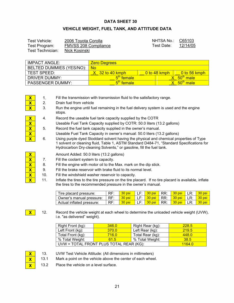
DATA SHEET 30 VEHICLE WEIGHT, FUEL TANK, AND ATTITUDE DATA
IMPACT ANGLE: Zero Degrees BELTED DUMMIES (YES/NO): No TEST SPEED: _X_ 32 to 40 kmph __ 0 to 48 kmph __ 0 to 56 kmph DRIVER DUMMY: __ 5th female _X_ 50th male PASSENGER DUMMY: __ 5th female _X_ 50th male X 1. Fill the transmission with transmission fluid to the satisfactory range. X 2. Drain fuel from vehicle X
3. Run the engine until fuel remaining in the fuel delivery system is used and the engine stops.
X 4. Record the useable fuel tank capacity supplied by the COTR X Useable Fuel Tank Capacity supplied by COTR: 50.0 liters (13.2 gallons) X 5. Record the fuel tank capacity supplied in the owner’s manual. X Useable Fuel Tank Capacity in owner’s manual: 50.0 liters (13.2 gallons) X
6. Using purple dyed Stoddard solvent having the physical and chemical properties of Type 1 solvent or cleaning fluid, Table 1, ASTM Standard D484-71, “Standard Specifications for Hydrocarbon Dry-cleaning Solvents,” or gasoline, fill the fuel tank.
X Amount Added: 50.0 liters (13.2 gallons) X 7. Fill the coolant system to capacity. X 8. Fill the engine with motor oil to the Max. mark on the dip stick. X 9. Fill the brake reservoir with brake fluid to its normal level. X 10. Fill the windshield washer reservoir to capacity. X
11. Inflate the tires to the tire pressure on the tire placard. If no tire placard is available, inflate the tires to the recommended pressure in the owner’s manual.
Tire placard pressure: RF: 30 psi LF: 30 psi RR: 30 psi LR: 30 psi Owner’s manual pressure: RF: 30 psi LF: 30 psi RR: 30 psi LR: 30 psi Actual inflated pressure: RF: 30 psi LF: 30 psi RR: 30 psi LR: 30 psi
X
12. Record the vehicle weight at each wheel to determine the unloaded vehicle weight (UVW), i.e. "as delivered” weight).
Right Front (kg): 346.0 Right Rear (kg): 228.5 Left Front (kg): 370.0 Left Rear (kg): 219.5 Total Front (kg): 716.0 Total Rear (kg): 448.0 % Total Weight: 61.5 % Total Weight: 38.5 UVW = TOTAL FRONT PLUS TOTAL REAR (KG): 1164.0
X 13. UVW Test Vehicle Attitude: (All dimensions in millimeters) X 13.1 Mark a point on the vehicle above the center of each wheel.
X 13.2 Place the vehicle on a level surface.
Test Vehicle: 2006 Toyota Corolla Test Program: FMVSS 208 Compliance Test Technician: Nick Kosinski
NHTSA No.: C65103 Test Date: 12/14/05

22
X
13.3 Measure perpendicular to the level surface to the 4 points marked on the body and record the measurements
RF: 691 LF: 681 RR: 703 LR: 703
X 14. Calculate the Rated Cargo and Luggage Weight (RCLW): 45 kg
X 14.1 Does the vehicle have the vehicle capacity weight (VCW) on the certification label or tire placard?
X X Yes, go to 14.3 No, go to 14.2
14.2 VCW = Gross Vehicle Weight – UVW
VCW = __________ - __________ = __________
X 14.3 VCW = 385 kg (850 lbs)
X 14.4 Does the certification or tire placard contain the Designated Seating Capacity (DSC)?
X Yes, go to 14.6 No, go to 14.5 and skip 14.6
14.5 DSC = Total number of seat belt assemblies = _________
X 14.6 DSC = 5
X 14.7 RCLW = VCW – (68 kg x DSC) = 385 kg - (68 kg x 5 ) = 45 kg
X
14.8 Is the vehicle certified as a truck, MPV or bus (see the certification label on the door jamb)?
Yes, if the calculated RCLW is greater than 136 kg, use 136 kg as the RCLW. (S8.1.1) X No, use the RCLW calculated in 14.7
X 15. Fully Loaded Weight (100% fuel fill): 1366.0 kg X
15.1 Place the appropriate test dummy in both front outboard seating positions. Driver: __ 5th female X 50th male Passenger: __ 5th female X 50th male
X 15.2 Load the vehicle with the RCLW from 14.7 or 14.8 whichever is applicable.
X 15.3 Place the RCLW in the cargo area. Center the load over the longitudinal centerline of the vehicle. (S8.1.1 (d))
X
15.4 Record the vehicle weight at each wheel to determine the Fully Loaded Weight.
Right Front (kg): 388.5 Right Rear (kg): 288.0 Left Front (kg): 410.0 Left Rear (kg): 279.5 Total Front (kg): 798.5 Total Rear (kg): 567.5 % Total Weight: 58.5 % Total Weight: 41.5 % GVW 52.6 % GVW 48.0 (% GVW = Axle GVW divided by Vehicle GVW) Fully Loaded Weight = Total Front Plus Total Rear (kg): 1366.0
X 16. Fully Loaded Test Vehicle Attitude: (All dimensions in millimeters) X 16.1 Place the vehicle on a level surface.

23
X
16.2 Measure perpendicular to the level surface to the 4 points marked on the body (see 13.1 above) and record the measurements
RF: 675 LF: 667 RR: 672 LR: 673
X 17. Drain the fuel system X
18. Using purple dyed Stoddard solvent having the physical and chemical properties of Type 1 solvent or cleaning fluid, Table 1, ASTM Standard D484-71, “Standard Specifications for Hydrocarbon Dry-cleaning Solvents,” fill the fuel tank to 92 - 94 percent of useable capacity.
X Fuel tank capacity x .94 = 50.0 liters (13.2 gallons) x .94 = 47.0 liters (12.4 gallons) X Amount added 47.0 liters (12.4 gallons) 94% X 19. Crank the engine to fill the fuel delivery system with Stoddard solvent X 20. Calculate the test weight range. X
20.1 Calculated Weight = UVW (see 12 above) + RCLW (see 14 above) + 2x(dummy weight) 1365.0 kg = 1164.0 kg + 45.0 kg + 156.0 kg
X
20.2 Test Weight Range = Calculated Weight (- 4.5 kg, - 9 kg.) Max. Test Weight = Calculated Test Weight – 4.5 kg = 1360.5 kg Min. Test Weight = Calculated Test Weight – 9 kg = 1356.0 kg
X 21. Remove the RCLW from the cargo area. X
22. Drain transmission fluid, engine coolant, motor oil, and windshield washer fluid from the test vehicle so that Stoddard solvent leakage from the fuel system will be evident.
X
23. Vehicle Components Removed For Weight Reduction: Spare tire, tool and jack, wheel covers, and trunk interior
X
24. Secure the equipment and ballast in the load carrying area and distribute it, as nearly as possible, to obtain the proportion of axle weight indicated by the gross axle weight ratings and center it over the longitudinal centerline of the vehicle.
X 25. If necessary, add ballast to achieve the actual test weight.
N/A
X Weight of Ballast: 18.1 kg
X
26. Ballast, including test equipment, must be contained so that it will not shift during the impact event or interfere with data collection or interfere with high-speed film recordings or affect the structural integrity of the vehicle or do anything else to affect test results. Care must be taken to assure that any attachment hardware added to the vehicle is not in the vicinity of the fuel tank or lines.
X 27. Record the vehicle weight at each wheel to determine the actual test weight.
Right Front (kg): 378.5 Right Rear (kg): 285.5 Left Front (kg): 427.0 Left Rear (kg): 269.0 Total Front (kg): 805.5 Total Rear (kg): 554.5 % Total Weight: 59.2 % Total Weight: 40.8 % GVW 52.6 % GVW 48.0 (% GVW = Axle GVW divided by Vehicle GVW) TOTAL FRONT PLUS TOTAL REAR (kg): 1360.0

24
X 28. Is the test weight between the Max. Weight and the Min. Weight (See 20.2)?
X Yes No, explain why not.
X 29. Test Weight Vehicle Attitude: (all dimensions in millimeters)
X 29.1 Place the vehicle on a level surface
X
29.2 Measure perpendicular to the level surface to the 4 points marked on the body (see 13 above) and record the measurements
RF: 682 LF: 668 RR: 698 LR: 693
X 30. Summary of test attitude
X
30.1 AS DELIVERED:
RF: 691 LF: 681 RR: 703 LR: 703
AS TESTED:
RF: 682 LF: 668 RR: 698 LR: 693
FULLY LOADED:
RF: 675 LF: 667 RR: 672 LR: 673
X
30.2 Is the “as tested” test attitude equal to or between the “fully loaded” and “as delivered” attitude?
X Yes No, explain why not.
REMARKS: I certify that I have read and performed each instruction.
Signature: _____________________ Date: 12/14/05

25
DATA SHEET 31 VEHICLE ACCELEROMETER LOCATION AND MEASUREMENT
IMPACT ANGLE: Zero Degrees BELTED DUMMIES (YES/NO): No TEST SPEED: _X_ 32 to 40 kmph __ 0 to 48 kmph __ 0 to 56 kmph DRIVER DUMMY: __ 5th female _X_ 50th male PASSENGER DUMMY: __ 5th female _X_ 50th male X
1. Find the location where the vertical plane parallel to the longitudinal centerline of the vehicle and through the center of the left front outboard seating position intersects the left rear seat cross member. Install an accelerometer at this intersection on the rear seat cross member to record x-direction accelerations. Record the location on the following chart.
X
2. Find the location where the vertical plane parallel to the longitudinal centerline of the vehicle and through the center of the right front outboard seating position intersects the right rear seat cross member. Install an accelerometer at this intersection on the rear seat cross member to record x-direction accelerations. Record the location on the following chart.
X
3. Find the location where a vertical plane through the longitudinal centerline of the vehicle and a vertical transverse plane through the center of the two wheels on opposite sides of the engine intersect at the top of the engine. Install an accelerometer at this intersection to record x-direction accelerations. Record the location on the following chart.
X
4. Find the location where a vertical plane through the longitudinal centerline of the vehicle and a vertical transverse plane through the center of the two wheels on opposite sides of the engine intersect the bottom of the engine. Install an accelerometer at this intersection to record x-direction accelerations. Record the location on the following chart
X
5. Install an accelerometer on the right front brake caliper to record x-direction accelerations. Record the location on the following chart
X
6. Find the location where a vertical plane through the longitudinal centerline of the vehicle intersects the top of the instrument panel. Install an accelerometer at this intersection to record x-direction accelerations. Record the location on the following chart
X
7. Install an accelerometer on the left front brake caliper to record x-direction accelerations. Record the location on the following chart
X
8. Find the location where a vertical plane through the longitudinal centerline of the vehicle intersects the floor of the trunk. Install an accelerometer on the trunk floor at this intersection to record z-direction accelerations. Record the location on the following chart
REMARKS: I certify that I have read and performed each instruction.
Signature: _____________________ Date: 12/14/05
Test Vehicle: 2006 Toyota Corolla Test Program: FMVSS 208 Compliance Test Technician: Nick Kosinski
NHTSA No.: C65103 Test Date: 12/14/05

26
LEFT SIDE VIEW
TOP VIEW
12
3 XZ
ENGINE
CENTERLINE
1
3
2
XY
REAR SEAT CUSHIONASSY. FRONT ATTACHMENTBRACKET SUPPORT
VEHICLE ACCELEROMETER LOCATIONAND DATA SUMMARY
ENGINE
5
6
5
6
4
7
BOTTOM OFOIL PAN
7
8
ACCELEROMETER COORDINATE SYSTEM(POSITIVE DIRECTION SHOWN)
CENTERLINE OFFRONT WHEELS
J
F
B
A
DISC BRAKECALIPER
84
D
E
GH
K
C
Dimensions Corresponding To The Letters “A” Through “K” (Excluding “I”) Are
Recorded In The Table On The Following Page. Accelerometers Corresponding To The Numbers 1 Through 8 Are Specified On The
Preceding Page.

27
DATA SHEET 31 VEHICLE ACCELEROMETER LOCATION AND MEASUREMENTS
DIMENSION LENGTH (mm)
PRETEST VALUES
A (LH Rear Seat Xmbr) 353
B (RH Rear Seat Xmbr) 353
C (Engine Top) 3748
D (Engine Bottom) 3567
E (Caliper) Right Side 3712 Left Side 3710
F (Left Caliper) 629
G (IP) 3026
H (Seat) 1864
J (Right Caliper) 634
K (Trunk) 946
POST TEST VALUES
A (LH Rear Seat Xmbr) 353
B (RH Rear Seat Xmbr) 353
C (Engine Top) 3645
D (Engine Bottom) 3592
E (Caliper) Right Side 3704 Left Side 3701
F (Left Caliper) 624
G (IP) 3019
H (Seat) 1864
J (Right Caliper) 630
K (Trunk) 945

28
DATA SHEET 32 PHOTOGRAPHIC TARGETS
IMPACT ANGLE: Zero Degrees BELTED DUMMIES (YES/NO): No TEST SPEED: _X_ 32 to 40 kmph __ 0 to 48 kmph __ 0 to 56 kmph DRIVER DUMMY: __ 5th female _X_ 50th male PASSENGER DUMMY: __ 5th female _X_ 50th male X 1. FMVSS 208 vehicle targeting requirements (See Figures 28A and 28B) X 1.1 Targets A1 and A2 are on flat rectangular panels.
X
1.2 Three circular targets at least 90 mm in diameter and with black and yellow quadrants are mounted at the front on the outboard sides of A1 and A2. The center of each circular target is 100 mm from the one next to it.
X Distance between targets (mm): 100 mm
X
1.3 Three circular targets at least 90 mm in diameter and with black and yellow quadrants are mounted at the back on the outboard sides of on A1 and A2. The center of each circular target is 100 mm from the one next to it.
X Distance between targets (mm): 100 mm
X
1.4 The distance between the first circular target at the front of A1 and A2 and the last circular target at the back of A1 and A2 is at least 915 mm.
X Distance between the first and last circular targets (mm): 915 mm
X
1.5 Firmly fix target A1 on the vehicle roof in the vertical longitudinal plane that is coincident with the midsagittal plane of the driver dummy.
X
1.6 Firmly fix target A2 on the vehicle roof in the vertical longitudinal plane that is coincident with the midsagittal plane of the passenger dummy.
X
1.7 Two circular targets (C1 and C2) at least 90 mm in diameter and with black and yellow quadrants are mounted on the outside of the driver door. The centers of each circular target are at least 610 mm apart.
X Distance between targets (mm): 614 mm
X
1.8 Two circular targets (C1 and C2) at least 90 mm in diameter and with black and yellow quadrants are mounted on the outside of the passenger door. The centers of each circular target are at least 610 mm apart.
X Distance between targets (mm): 611 mm
X
1.9 Place tape with squares having alternating colors on the top portion of the steering wheel.
X 1.10 Chalk the bottom portion of the steering wheel
X 1.11 Is this an offset test?
Yes, continue with this section X No, go to 2. 1.12 Measure the width of the vehicle. Vehicle width (mm):
Test Vehicle: 2006 Toyota Corolla Test Program: FMVSS 208 Compliance Test Technician: Nick Kosinski
NHTSA No.: C65103 Test Date: 12/14/05

29
1.13 Find the centerline of the vehicle. (½ of the vehicle width)
1.14 Find the line parallel to the centerline of the vehicle and 0.1 x vehicle width from the centerline of the vehicle.
1.15 Apply 25 mm wide tape with alternating black and yellow squares parallel to and on each side of the line found in 1.14. The edge of each tape shall be 50 mm from the line found in 1.14. The tape shall extend from the bottom of the bumper to the front edge of the windshield. (Figure 28D
X 2. Barrier Targeting X
2.1 Fix two stationary targets D1 and D2 to the barrier as shown in the Figure 28A. One target is in the vertical longitudinal plane that is coincident with the midsagittal plane of the driver dummy. The other is in the vertical longitudinal plane that is coincident with the midsagittal plane of the passenger dummy
X 2.2 Targets D1 and D2 are on a rectangular panel. X
2.3 Three circular targets at least 90 mm in diameter and with black and yellow quadrants are mounted on the sides of the rectangular panel away from the longitudinal centerline of the vehicle. The center of each circular target is 100 mm from the one next to it.
X Distance between circular targets on D1 (mm): 100 mm
X Distance between circular targets on D2 (mm): 100 mm
X 3. FMVSS 208 Dummy Targeting Requirements X
3.1 Place a circular target with black and yellow quadrants on both sides of the driver dummy head as close as possible to the center of gravity of the head in the x and z direction (relative to the measuring directions of the accelerometers).
X
3.2 Place a circular target with black and yellow quadrants on both sides of the passenger dummy head as close as possible to the center of gravity of the head in the x and z direction (relative to the measuring directions of the accelerometers).
X
3.3 Place a circular target with black and yellow quadrants on the outboard shoulder of the driver dummy. Place the target as high up on the arm as possible at the intersection of the arm and shoulder. The sleeve of the shirt on the dummy may be cut to make the target visible, but do not remove any material.
X
3.4 Place a circular target with black and yellow quadrants on the outboard shoulder of the passenger dummy. Place the target as high up on the arm as possible at the intersection of the arm and shoulder. The sleeve of the shirt on the dummy may be cut to make the target visible, but do not remove any material.
X 4. FMVSS 204 Targeting Requirements
X 4.1 Is an FMVSS 204 indicant test ordered on the “COTR Vehicle Work Order?”
Yes, continue with this form. X No, this form is complete. 4.2 Resection panel (Figure 28C)
4.2.1 The panel deviates no more than 6 mm from perfect flatness when suspended vertically
4.2.2 The 8 targets on the panel are circular targets at least 90 mm in diameter and with black and yellow quadrants.
4.2.3 The center of each of the 4 outer targets are placed within 1 mm of the corners of a square measuring 914 mm on each side.
4.2.4 Locate another square with 228 mm sides and with the center of this square coincident with the center of the 914 mm square.
4.2.5 The center of the 4 inner targets are placed at the midpoints of each of the 228 mm sides.

30
4.3 Place a circular target at least 90 mm in diameter and with black and yellow quadrants on a material (cardboard, metal, etc.) that can be taped to the top of the steering column.
4.4 Tape the target from 4.3 to the top of the steering column in a manner that does not interfere with the movement of the steering column in a crash
I certify that I have read and performed each instruction.
Signature: _____________________ Date: 12/14/05

31
LEFT SIDE VIEW
COVERED PHOTO PIT
915 mm
100 mm 100 mm
A1
610 mm
REFERENCE PHOTO TARGETS
MONORAIL
C2
B
C1
CONCRETEBARRIER
32
C1 C2
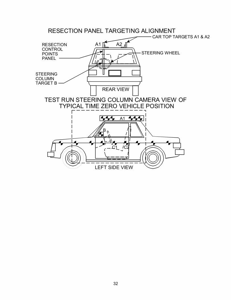
B
RESECTION PANEL TARGETING ALIGNMENT
LEFT SIDE VIEW
REAR VIEW
TEST RUN STEERING COLUMN CAMERA VIEW OF TYPICAL TIME ZERO VEHICLE POSITION
CAR TOP TARGETS A1 & A2
STEERING WHEEL
A1
STEERINGCOLUMNTARGET B
RESECTIONCONTROLPOINTSPANEL
A1 A2

33
PRE-RUN STEERING COLUMN HIGH SPEED CAMERA VIEW
LEFT SIDE VIEW
914 mm

34
DATA SHEET 33 CAMERA LOCATIONS
CAMERA NO.
VIEW
CAMERA POSITIONS (mm) *
LENS (mm)
SPEED (fps)
X Y Z
1 Real Time Left Side View 13 24
2 Left Side View (Barrier face to front seat backs) 990 -4870 1375 24 1000
3 Left Side View (Driver) 1570 -5970 1470 35 1000
4 Left Side View (B-post aimed toward center of steering wheel) 6715 -5660 2165 50 1000
5 Left Side View (Steering Column) 1440 -5500 1470 25 1000
6 Left Side View (Steering Column) 1470 -5480 1025 25 1000
7 Right Side View (Overall) 2000 6020 1500 19 1000
8 Right Side View (Passenger) 1350 5990 1420 35 1000
9 Right Side View (Angle) 6880 5095 2190 50 1000
10 Right Side View (Front door) 1010 4850 1460 24 1000 11 Front View Windshield -285 0 2370 12.5 1000 12 Front View Driver -145 -425 2215 16 1000 13 Front View Passenger -145 505 2220 16 1000 14 Overhead Barrier Impact View 885 0 5050 19 1000 15 Pit Camera Engine View 1130 0 -3150 24 1000 16 Pit Camera Fuel Tank View 3440 0 -3150 24 1000
*COORDINATES:
+X - forward of impact plane +Y - right of monorail centerline +Z - above ground level
Test Vehicle: 2006 Toyota Corolla Test Program: FMVSS 208 Compliance
NHTSA No.: C65103 Test Date: 12/14/05 Time: 1:22 pm

35
LEFT SIDE VIEW
TOP VIEW
MONORAIL
COVERED PHOTO PIT
TOW ROAD
COVERED PHOTO PIT
REAL TIME CAMERA
2
8
15 16
CONCRETE PAD
14
6
9
5
3
CAMERA POSITIONS FOR FMVSS 208
13
12
MONORAIL
CONCRETEBARRIER
CONCRETEBARRIER
11
4
7
10
111
14
12
36
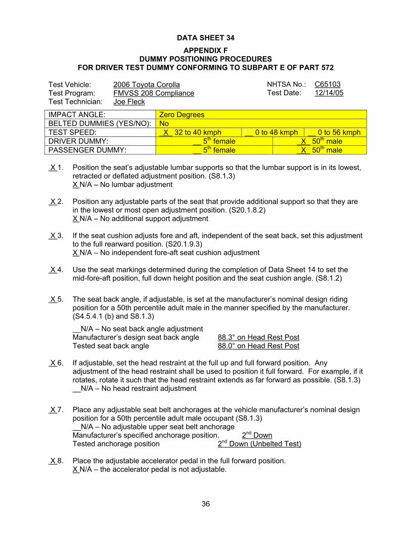
DATA SHEET 34 APPENDIX F
DUMMY POSITIONING PROCEDURES FOR DRIVER TEST DUMMY CONFORMING TO SUBPART E OF PART 572
IMPACT ANGLE: Zero Degrees BELTED DUMMIES (YES/NO): No TEST SPEED: _X_ 32 to 40 kmph __ 0 to 48 kmph __ 0 to 56 kmph DRIVER DUMMY: __ 5th female _X_ 50th male PASSENGER DUMMY: __ 5th female _X_ 50th male X 1. Position the seat’s adjustable lumbar supports so that the lumbar support is in its lowest,
retracted or deflated adjustment position. (S8.1.3) X N/A – No lumbar adjustment X 2. Position any adjustable parts of the seat that provide additional support so that they are
in the lowest or most open adjustment position. (S20.1.8.2) X N/A – No additional support adjustment X 3. If the seat cushion adjusts fore and aft, independent of the seat back, set this adjustment
to the full rearward position. (S20.1.9.3) X N/A – No independent fore-aft seat cushion adjustment X 4. Use the seat markings determined during the completion of Data Sheet 14 to set the
mid-fore-aft position, full down height position and the seat cushion angle. (S8.1.2)
X 5. The seat back angle, if adjustable, is set at the manufacturer’s nominal design riding position for a 50th percentile adult male in the manner specified by the manufacturer. (S4.5.4.1 (b) and S8.1.3)
__N/A – No seat back angle adjustment Manufacturer’s design seat back angle 88.3° on Head Rest Post Tested seat back angle 88.0° on Head Rest Post X 6. If adjustable, set the head restraint at the full up and full forward position. Any
adjustment of the head restraint shall be used to position it full forward. For example, if it rotates, rotate it such that the head restraint extends as far forward as possible. (S8.1.3)
__N/A – No head restraint adjustment
X 7. Place any adjustable seat belt anchorages at the vehicle manufacturer’s nominal design position for a 50th percentile adult male occupant (S8.1.3) __N/A – No adjustable upper seat belt anchorage Manufacturer’s specified anchorage position. 2nd Down Tested anchorage position 2nd Down (Unbelted Test)
X 8. Place the adjustable accelerator pedal in the full forward position. X N/A – the accelerator pedal is not adjustable.
Test Vehicle: 2006 Toyota Corolla Test Program: FMVSS 208 Compliance Test Technician: Joe Fleck
NHTSA No.: C65103 Test Date: 12/14/05

37
X 9. Set the steering wheel hub at the geometric center of the full range of driving positions including any telescoping positions as determined in data sheet 14.
X 10. Place the dummy in the seat such that the midsagittal plane is coincident with the
longitudinal seat cushion markings as determined in item 1.18 of Data Sheet 14 and the upper torso rests against the seat back. (S10.4.1.1 & S10.4.1.2)
X 11. Rest the thighs on the seat cushion. (S10.5) X 12. Position the H-point of the dummy within 0.5 inch of the vertical dimension and 0.5 inch
of the horizontal dimension of a point 0.25 inch below the H-point determined by using the equipment and procedures specified in SAE J826 (APR 1980). (S10.4.2.1) Then measure the pelvic angle with respect to the horizontal using the pelvic angle gage.
Adjust the dummy position until these three measurements are within the specifications. (S10.4.2.1 and S10.4.2.2)
.270 horizontal inches from the point 0.25 below the determined H-point (0.5 inch max.) (S10.4.2.1)
.030 vertical inches from the point 0.25 below the determined H-point (0.5 inch max.) (S10.4.2.1)
24.8° pelvic angle (20o to 25o) X 13. Is the head level within ± 0.5o? (S10.1) _ Yes, go to 14 X No, go to 13.1 X 13.1 Adjust the position of the H-point. (S10.1) X 13.2 Is the head level within ± 0.5o? (S10.1) __Yes, record the following, then go to 15. X No, go to 13.3 ____horizontal inches from the point 0.25 below the determined H-point (0.5 inch max.)
(S10.4.2.1) ____vertical inches from the point 0.25 below the determined H-point (0.5 inch max.)
(S10.4.2.1) ____pelvic angle (20o to 25o) (S10.4.2.2) X 13.3 Adjust the pelvic angle. (S10.1) X 13.4 Is the head level within ± 0.5o? (S10.1) __Yes, record the following, then go to 14. X No, go to 13.5 ____horizontal inches from the point 0.25 below the determined H-point (0.5 inch max.)
(S10.4.2.1) ____vertical inches from the point 0.25 below the determined H-point (0.5 inch max.)
(S10.4.2.1) ____pelvic angle (20o to 25o) (S10.4.2.2)

38
X 13.5 Adjust the neck bracket of the dummy the minimum amount necessary from the non-adjusted “0” setting until the head is level within ± 0.5o. (S10.1)
Record the following, then go to 14 (The neck bracket was moved one notch) .226 horizontal inches from the point 0.25 below the determined H-point (0.5 inch max.) (S10.4.2.1)
.438 vertical inches from the point 0.25 below the determined H-point (0.5 inch max.) (S10.4.2.1)
22.5° pelvic angle (20o to 25o) X 14. Set the distance between the outboard knee clevis flange surfaces at 10.6 inches. 10.6” measured distance (10.6 inches) (S10.5) X 15. Can the right foot be placed on the accelerator? X Yes, go to 15.1 and skip 15.2 __No, go to 15.2 X 15.1.To the extent practicable keep the right thigh and the leg in a vertical plane (S10.5)
while resting the foot on the undepressed accelerator pedal with the rearmost point of the heel on the floor pan in the plane of the pedal. (S10.6.1.1)
__15.2 Initially set the foot perpendicular to the leg and then place it as far forward as possible
in the direction of the pedal centerline with the rearmost point of the heel resting on the floor pan. (S10.6.1.1)
__15.2.1 Move the adjustable pedal to its most rearward position or until the right foot is flat on
the pedal, whichever occurs first. (S10.6.1.1) __N/A – the accelerator pedal is not adjustable X 16. Does the vehicle have a foot rest? X Yes, go to 16.1 __No, go to 16.2 X 16.1 With the left thigh and leg in a vertical plane, place the foot on the foot rest with the heel
resting on the floor pan. (S10.6.1.2) X 16.1.1 Is the left foot elevated above the right foot? __Yes, go to 16.1.2 and position the foot off the foot rest X No, go to 17 __16.1.2 Check the ONLY one of the following that applies __The foot reaches the toeboard without adjusting the foot or leg. To the extent
practicable keep the left thigh and the leg in a vertical longitudinal plane (S10.5) and place the foot on the toeboard, skip 16.1.3 (S10.6.1.2)
__The foot reaches the toeboard but contacts the brake or clutch pedal and must be
rotated to avoid pedal contact. To the extent practicable keep the left thigh and the leg in a vertical longitudinal plane (S10.5) and place the foot on the toeboard. The foot was rotated about the leg to avoid pedal contact, skip 16.1.3 (S10.6.1.2)

39
__The foot reaches the toeboard but contacts the brake or clutch pedal and the foot and leg must be rotated to avoid pedal contact. To the extent practicable keep the left thigh and the leg in a vertical longitudinal plane (S10.5) and place the foot on the toeboard. The foot was rotated about the leg and the leg was rotated outboard about the hip the minimum distance necessary to avoid pedal contact, skip 16.1.3 (S10.6.1.2)
__N/A – the foot does not reach the toeboard, go to 16.1.3
__16.1.3 Check the ONLY one of the following that applies
__The foot did not contact the brake or clutch pedal. To the extent practicable keep the left thigh and the leg in a vertical longitudinal plane (S10.5). Set the foot perpendicular to the leg and place it as far forward as possible with the heel resting on the floor pan. (S10.6.1.2)
__The foot did contact the brake or clutch pedal and the foot was rotated to avoid
contact. To the extent practicable keep the left thigh and the leg in a vertical longitudinal plane (S10.5). Set the foot perpendicular to the leg and place it as far forward as possible with the heel resting on the floor pan and rotate the foot the minimum amount to avoid pedal contact. (S10.6.1.2)
__The foot did contact the brake or clutch pedal and the foot was rotated about the leg
and the leg was rotated outboard about the hip the minimum distance necessary to avoid pedal contact. Set the foot perpendicular to the leg and place it as far forward as possible with the heel resting on the floor pan and rotate the foot about the leg and the thigh and leg outboard about the hip the minimum distance necessary to avoid pedal contact. (S10.6.1.2)
X 17. Place the right upper arm adjacent to the torso with the centerline as close to a vertical
plane as possible. (S10.2.1) X 18. Is the driver seat belt used for this test? __Yes, continue X No, go to 19 __18.1 Fasten the seat belt around the dummy. __18.2 Remove all slack from the lap belt portion. (S10.9) __18.3 Pull the upper torso webbing out of the retractor and allow it to retract; repeat this four
times. (S10.9) __18.4 Apply a 2 to 4 pound tension load to the lap belt. (S10.9) ____pound load applied __18.5 Is the belt system equipped with a tension-relieving device? __Yes, continue __No, go to 19

40
__18.6 Introduce the maximum amount of slack into the upper torso bet that is recommended by the vehicle manufacturer in the vehicle owner’s manual. (S10.9).
X 19. Place the left upper arm adjacent to the torso with the centerline as close to a vertical
plane as possible. (S10.2.1) X 20. Place the right hand with the palm in contact with the steering wheel at the rim’s
horizontal centerline and with the thumb over the steering wheel. (S10.3.1) X 21. Place the left hand with the palm in contact with the steering wheel at the rim’s horizontal
centerline and with the thumb over the steering wheel. (S10.3.1) X 22. Tape the thumb of each hand to the steering wheel by using masking tape with a width
of 0.25 inch. The length of the tape shall only be enough to go around the thumb and steering wheel one time.
REMARKS: I certify that I have read and performed each instruction.
Signature: Date: 12/14/05

41
APPENDIX F DUMMY POSITIONING PROCEDURES FOR PASSENGER TEST DUMMY CONFORMING
TO SUBPART E OF PART 572
IMPACT ANGLE: Zero Degrees BELTED DUMMIES (YES/NO): No TEST SPEED: _X_ 32 to 40 kmph __ 0 to 48 kmph __ 0 to 56 kmph DRIVER DUMMY: __ 5th female _X_ 50th male PASSENGER DUMMY: __ 5th female _X_ 50th male X 1. The seat is a bench seat for which the adjustments have already been made for the
driver and there are no independent adjustments that can be made for the passenger. Go to 7.
X N/A- the passenger seat adjusts independently of the driver seat. X 2. Position the seat’s adjustable lumbar supports so that the lumbar support is in its lowest,
retracted or deflated adjustment position. (S8.1.3) X N/A – No lumbar adjustment X 3. Position any adjustable parts of the seat that provide additional support so that they are
in the lowest or most open adjustment position. (S20.1.8.2) X N/A – No additional support adjustment X 4. If the seat cushion adjusts fore and aft, independent of the seat back, set this adjustment
to the full rearward position. (S20.1.9.3) X N/A – No independent fore-aft seat cushion adjustment X 5. Use the seat markings determined during the completion of Data Sheet 14 to set the
mid-fore-aft position, full down height position and the seat cushion angle. (S8.1.2)
X 6. The seat back angle, if adjustable, is set at the manufacturer’s nominal design riding position for a 50th percentile adult male in the manner specified by the manufacturer. (S4.5.4.1 (b) and S8.1.3)
__N/A – No seat back angle adjustment Manufacturer’s design seat back angle 89.0° on Head Rest Post Tested seat back angle 89.0° on Head Rest Post X 7. If adjustable, set the head restraint at the full up and full forward position. Any
adjustment of the head restraint shall be used to position it full forward. For example, if it rotates, rotate it such that the head restraint extends as far forward as possible. (S8.1.3)
__N/A – No head restraint adjustment
Test Vehicle: 2006 Toyota Corolla Test Program: FMVSS 208 Compliance Test Technician: Wayne Dahlke
NHTSA No.: C65103 Test Date: 12/14/05

42
X 8. Place any adjustable seat belt anchorages at the vehicle manufacturer’s nominal design position for a 50th percentile adult male occupant (S8.1.3) __N/A – No adjustable upper seat belt anchorage Manufacturer’s specified anchorage position. 2nd Down Tested anchorage position 2nd Down (Unbelted Test) __ N/A - the seat does not have a fore-aft adjustment
X 9. Place the dummy in the seat such that the midsagittal plane is coincident with the
longitudinal seat cushion markings as determined in item 2.19 of Data Sheet 14 and the upper torso rests against the seat back. (S10.4.1.1 & S10.4.1.2)
X 10. Rest the thighs on the seat cushion. (S10.5) X 11. Position the H-point of the dummy within 0.5 inch of the vertical dimension and 0.5 inch
of the horizontal dimension of a point 0.25 inch below the H-point determined by using the equipment and procedures specified in SAE J826 (APR 1980). (S10.4.2.1) Then measure the pelvic angle with respect to the horizontal using the pelvic angle gage.
Adjust the dummy position until these three measurements are within the specifications. (S10.4.2.1 and S10.4.2.2)
.276 horizontal inches from the point 0.25 below the determined H-point (0.5 inch max.) (S10.4.2.1)
.118 vertical inches from the point 0.25 below the determined H-point (0.5 inch max.) (S10.4.2.1)
23.8° pelvic angle (20o to 25o) X 12. Is the head level within ± 0.5o? (S10.1) __Yes, go to 13 X No, go to 12.1 X 12.1 Adjust the position of the H-point. (S10.1 and S10.4.2.1) X 12.2 Is the head level within ± 0.5o? (S10.1) __Yes, record the following, then go to 13. X No, go to 12.3 ____horizontal inches from the point 0.25 below the determined H-point (0.5 inch max.)
(S10.4.2.1) ____vertical inches from the point 0.25 below the determined H-point (0.5 inch max.)
(S10.4.2.1) ____pelvic angle (20o to 25o) (S10.4.2.2) X 12.3 Adjust the pelvic angle. (S10.1) X 12.4 Is the head level within ± 0.5o? (S10.1) __Yes, record the following, then go to 13. X No, go to 12.5 ____horizontal inches from the point 0.25 below the determined H-point (0.5 inch max.)
(S10.4.2.1) ____vertical inches from the point 0.25 below the determined H-point (0.5 inch max.)
(S10.4.2.1) ____pelvic angle (20o to 25o) (S10.4.2.2)

43
X 12.5 Adjust the neck bracket of the dummy the minimum amount necessary from the non-adjusted “0” setting until the head is level within ± 0.5o. (S10.1)
Record the following, then go to 13 (The neck bracket was moved four notches) .188 horizontal inches from the point 0.25 below the determined H-point (0.5 inch max.)
(S10.4.2.1) .289 vertical inches from the point 0.25 below the determined H-point (0.5 inch max.)
(S10.4.2.1) 23.4°pelvic angle (20o to 25o) (S10.4.2.2) X 13. Set the distance between the outboard knee clevis flange surfaces at 10.6 inches. 10.6” measured distance (10.6 inches) (S10.5) X 14. Check the only one of the following that applies: X To the extent practicable keep the left thigh and leg in a vertical plane and the right
thigh and leg in a vertical plane, place the feet on the toeboard with the heels resting on the floor pan as close as possible to the intersection of the floor pan and toeboard.
__The feet cannot be placed flat on the toeboard. To the extent practicable keep the left thigh and leg in a vertical plane and the right thigh and leg in a vertical plane, set the feet perpendicular to the legs and place them as far forward as possible with the heels resting on the floor pan.
__The vehicle has a wheelhouse projection. To the extent practicable keep the left thigh and leg in a vertical plane and the right thigh and leg in a vertical plane, set the feet perpendicular to the legs and place them as far forward as possible with the heels resting on the floor pan. Do not set the feet on the wheelhouse projection.
__The vehicle has a wheelhouse projection and the feet cannot be placed on the toeboard. To the extent practicable keep the left thigh and leg in a vertical plane and the right thigh and leg in a vertical plane, set the feet perpendicular to the legs and place them as far forward as possible with the heel resting on the floor pan. . Do not set the feet on the wheelhouse projection.
X 15. Place the left upper arm in contact with the seat back and side of the torso. (S10.2.2) X 16. Is the passenger seat belt used for this test? __Yes, continue X No, go to 17 __16.1 Fasten the seat belt around the dummy. __16.2 Remove all slack from the lap belt portion. (S10.9) __16.3 Pull the upper torso webbing out of the retractor and allow it to retract; repeat this four
times. (S10.9) __16.4 Apply a 2 to 4 pound tension load to the lap belt. (S10.9) ____pound load applied

44
__16.5 Is the belt system equipped with a tension relieving device? __Yes, continue __No, go to 17 __16.6 Introduce the maximum amount of slack into the upper torso bet that is recommended by
the vehicle manufacturer in the vehicle owner’s manual. (S10.9). Go to 17. X 17. Place the right upper arm in contact with the seat back and side of the torso. (S10.2.2) X 18. Place the left hand palm in contact with the outside of the left thigh and the little finger in
contact with the seat cushion. (S10.3.2) X 19. Place the right hand palm in contact with the outside of the right thigh and the little finger
in contact with the seat cushion. (S10.3.2) REMARKS: I certify that I have read and performed each instruction. Signature: ____________________ Date: 12/14/05

45
DATA SHEET 35 DUMMY MEASUREMENTS
DUMMY MEASUREMENTS FOR FRONT SEAT OCCUPANTS
PASS
DRVR
Vertical Longitudinal Planes
Vertical Transverse
Plane
HS
KK
AD
HD
HR
SHY
STRIKER
HZ
CD
KD
CS
Seat Back Angle Line
SH
NR
SK
AD Arm to Door HD H-Point to Door HR Head to Side Header HS Head to Side Window KK Knee to Knee SHY Striker to H-Point (Y Axis)
CD Chest to Dash CS Chest to Steering Wheel Hub HH Head to Header HW Head to Windshield HZ Head to Roof KDA Knee to Dash Angle KDL Left Knee to Dash KDR Right Knee to Dash NA Nose to Rim Angle NR Nose to Rim PA Pelvic Angle RA Rim to Abdomen SA Seat Back Angle SCA Steering Column Angle SH Striker to H-Point SK Striker to Knee ST Striker to Head SWA Steering Wheel Angle TA Tibial Angle WA Windshield Angle
SWA° HH
WA° HW
NA°
SCA°
KDA°
TA° SA°
ST
PA°
Test Vehicle: 2006 Toyota Corolla Test Program: FMVSS 208 Compliance Test Technician: Eric Peschman
NHTSA No.: C65103 Test Date: 12/14/05

46
DATA SHEET 35 DUMMY MEASUREMENTS
TEST DUMMY POSITION MEASUREMENTS Code Measurement Description Driver SN 401 Passenger SN 403
Length (mm) Angle (°) Length (mm) Angle (°)
WA Windshield Angle 26.8
SWA Steering Wheel Angle 63.2
SCA Steering Column Angle 29.4
SA Seat Back Angle (On Headrest) 88.0 89.0
HZ Head to Roof (Z) 185 162
HH Head to Header 321 23.0 281 28.1
HW Head to Windshield 600 0.0 538 0.0
HR Head to Side Header (Y) 190 188
NR Nose to Rim 426 13.2
CD Chest to Dash 525 500
CS Chest to Steering Hub 345 6.1
RA Rim to Abdomen 210 0.0
KDL Left Knee to Dash 141 21.6 108
KDR Right Knee to Dash 138 142 27.7
PA Pelvic Angle 22.5 23.4
TA Tibia Angle 53.6 45.5
KK Knee to Knee (Y) 305 271
SK Striker to Knee 593 95.5 605 100.0
ST Striker to Head 420 11.9 467 16.0
SH Striker to H-Point 310 133.3 279 131.0
SHY Striker to H-Point (Y) 255 250
HS Head to Side Window 293 281
HD H-Point to Door (Y) 160 140
AD Arm to Door (Y) 111 96
AA Ankle to Ankle 310 181
Test Vehicle: 2006 Toyota Corolla Test Program: FMVSS 208 Compliance Test Technician: Eric Peschman
NHTSA No.: C65103 Test Date: 12/14/05
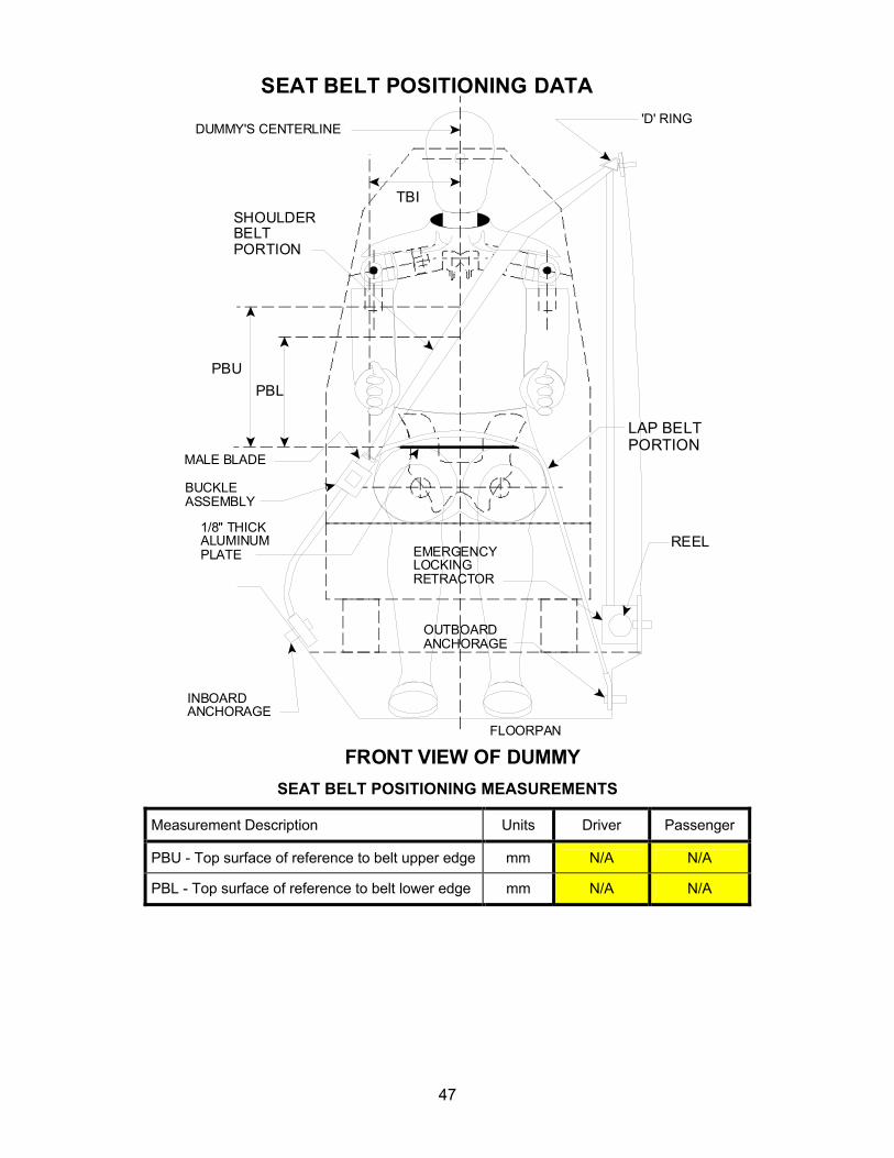
47
SEAT BELT POSITIONING DATA
DUMMY'S CENTERLINE
TBI
'D' RING
SHOULDERBELTPORTION
LAP BELTPORTION
1/8" THICKALUMINUMPLATE EMERGENCY
LOCKINGRETRACTOR
OUTBOARDANCHORAGE
INBOARDANCHORAGE
FLOORPAN
BUCKLEASSEMBLY
MALE BLADE
REEL
PBUPBL
FRONT VIEW OF DUMMY SEAT BELT POSITIONING MEASUREMENTS
Measurement Description Units Driver Passenger
PBU - Top surface of reference to belt upper edge mm N/A N/A
PBL - Top surface of reference to belt lower edge mm N/A N/A

48
DATA SHEET 36 CRASH TEST
IMPACT ANGLE: Zero Degrees BELTED DUMMIES (YES/NO): No TEST SPEED: _X_ 32 to 40 kmph __ 0 to 48 kmph __ 0 to 56 kmph DRIVER DUMMY: __ 5th female _X_ 50th male PASSENGER DUMMY: __ 5th female _X_ 50th male
X 1. Vehicle underbody painted X 2. The speed measuring devices are in place and functioning. X
3. The speed measuring devices are 1.0 m from the barrier (spec. 1.5m) and 30 cm from the barrier (spec. is 30 cm)
X 4. Convertible top is in the closed position.
X N/A, not a convertible X
5. Instrumentation and wires are placed so the motion of the dummies during impact is not affected.
X
6. Tires inflated to pressure on tire placard or if it does not have a tire placard because it is not a passenger car, then inflated to the tire pressure specified in the owner information.
210 kpa front left tire 210 kpa specified on tire placard or in owner information 210 kpa front right tire 210 kpa specified on tire placard or in owner information 210 kpa rear left tire 210 kpa specified on tire placard or in owner information 210 kpa rear right tire 210 kpa specified on tire placard or in owner information
X 7. Time zero contacts on barrier in place.
X 8. Pre test zero and shunt calibration adjustments performed and recorded
X 9. Dummy temperature meets requirements of section 12.2 of the test procedure.
X 10. Vehicle hood closed and latched
X 11. Transmission placed in neutral
X 12. Parking brake off
X 13. Ignition in the ON position
X 14. Doors closed and latched but not locked
X 15. Posttest zero and shunt calibration checks performed and recorded
X 16. Actual test speed 39.8 kmph
X 17. Vehicle rebound from the barrier 293 cm
X
18. Describe whether the doors open after the test and what method is used to open the doors.
X Left Front Door: Door remained closed and latched; Door opened without tools X Right Front Door: Door remained closed and latched; Door opened without tools X Left Rear Door: Door remained closed and latched; Door opened without tools X Right Rear Door: Door remained closed and latched; Door opened without tools
Test Vehicle: 2006 Toyota Corolla Test Program: FMVSS 208 Compliance Test Technician: Eric Peschman
NHTSA No.: C65103 Test Date: 12/14/05

49
X 19. Describe the contact points of the dummy with the interior of the vehicle.
X Driver Dummy: Head to Windshield, Air Bag and Headrest; Chest to Air Bag; Knees to Knee Bolster and Steering Column
X Passenger Dummy: Head to Visor, Air Bag, and Headrest; Chest to Air Bag; Knees to Glove Box and Dash
REMARKS: I certify that I have read and performed each instruction.
Signature: Date: 12/14/05

50
DATA SHEET NO. 38 ACCIDENT INVESTIGATION DIVISION DATA
IMPACT ANGLE: Zero Degrees BELTED DUMMIES (YES/NO): No TEST SPEED: _X_ 32 to 40 kmph __ 0 to 48 kmph __ 0 to 56 kmph DRIVER DUMMY: __ 5th female _X_ 50th male PASSENGER DUMMY: __ 5th female _X_ 50th male Vehicle Year/Make/Model/Body Style: 2006 Toyota Corolla Passenger Car
VIN: 1NXBR32EX6Z591914
Wheelbase: 2605 mm
Build Date: 09/05
Vehicle Size Category: 3
Test Weight: 1360.0 kg
Front Overhang: 910 mm
Overall Width: 1697 mm
Overall Length Center: 4515 mm
Accelerometer Data
Location: As per measurements on Data Sheet 31
Linearity: >99.9%
Integration Algorithm: Trapezoidal
Vehicle Impact Speed: 39.8 kmph
Time of Separation: 89.6 ms
Velocity Change: 43.7 kmph
Test Vehicle: 2006 Toyota Corolla Test Program: FMVSS 208 Compliance Test Technician: Nick Kosinski
NHTSA No.: C65103 Test Date: 12/14/05

51
CRUSH PROFILE
Collision Deformation Classification: 12FDEW6 Midpoint of Damage: Vehicle Longitudinal Centerline Damage Region Length (mm): 1522 Impact Mode: Frontal Barrier
No. Measurement Description Units Pre-Test Post-Test Difference
C1 Crush zone 1 at left side mm 4322 4125 197
C2 Crush zone 2 at left side mm 4445 4143 302
C3 Crush zone 3 at left side mm 4498 4133 365
C4 Crush zone 4 at right side mm 4498 4156 342
C5 Crush zone 5 at right side mm 4444 4175 269
C6 Crush zone 6 at right side mm 4326 4130 196
L/2L
C1 C2 C3 C4 C5 C6
L/2
REMARKS: I certify that I have read and performed each instruction.
Signature: _____________________ Date: 12/14/05

52
DATA SHEET 39 WINDSHIELD MOUNTING (FMVSS 212)
IMPACT ANGLE: Zero Degrees BELTED DUMMIES (YES/NO): No TEST SPEED: _X_ 32 to 40 kmph __ 0 to 48 kmph __ 0 to 56 kmph DRIVER DUMMY: __ 5th female _X_ 50th male PASSENGER DUMMY: __ 5th female _X_ 50th male
1. Pre-Crash X
1.1 Describe from visual inspection how the windshield is mounted and describe any trim material.
Retained with glue Rubber trim
X 1.2 Mark the longitudinal centerline of the windshield X 1.3 Measure pre-crash A, B, and C for the left side and record in the chart below.
X 1.4 Measure pre-crash C, D, and E for the right side and record in the chart below.
X 1.5 Measure from the edge of the retainer or molding to the edge of the windshield. X Dimension G (mm): 17 mm
2. Post Crash
X
2.1 Can a single thickness of copier type paper (as small a piece as necessary) slide between the windshield and the vehicle body?
X
No – Pass. Skip to the table of measurements, complete it by repeating the pre-crash measurements in the post crash column, and calculate the retention percentage, which will be 100%.
Yes, go to 2.2
2.2 Visibly mark the beginning and end of the portions of the periphery where the paper slides between the windshield and the vehicle body.
2.3 Measure and record post-crash A, B, C, D, E, and F such that the measurements do not include any of the parts of the windshield where the paper slides between the windshield and the vehicle body.
2.4 Calculate and record the percent retention for the right and left side of the windshield.
2.5 Is total right side percent retention less than 75%?
Yes, Fail No, Pass 2.6 Is total left side percent retention less than 75%?
Yes, Fail No, Pass
Test Vehicle: 2006 Toyota Corolla Test Program: FMVSS 208 Compliance Test Technician: Nick Kosinski
NHTSA No.: C65103 Test Date: 12/14/05
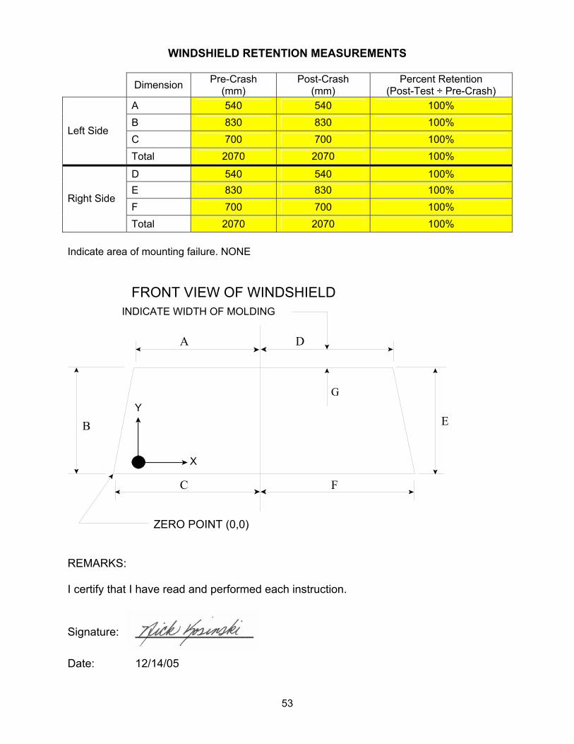
53
WINDSHIELD RETENTION MEASUREMENTS
Dimension Pre-Crash (mm)
Post-Crash (mm)
Percent Retention (Post-Test ÷ Pre-Crash)
A 540 540 100% B 830 830 100% C 700 700 100%
Left Side
Total 2070 2070 100%
D 540 540 100% E 830 830 100% F 700 700 100%
Right Side
Total 2070 2070 100% Indicate area of mounting failure. NONE
REMARKS: I certify that I have read and performed each instruction.
Signature: _____________________ Date: 12/14/05
ZERO POINT (0,0)
FRONT VIEW OF WINDSHIELDINDICATE WIDTH OF MOLDING
Y
X
G
A D
B
C F
E

54
A
D
E B F
C
Lower Edge of Protected Zone
FRONT VIEW OF WINDSHIELDZero Point
Y
X
DATA SHEET 40 WINDSHIELD ZONE INTRUSION (FMVSS 219)
IMPACT ANGLE: Zero Degrees BELTED DUMMIES (YES/NO): No TEST SPEED: _X_ 32 to 40 kmph __ 0 to 48 kmph __ 0 to 56 kmph DRIVER DUMMY: __ 5th female _X_ 50th male PASSENGER DUMMY: __ 5th female _X_ 50th male X
1. Place a 165 mm diameter rigid sphere, with a mass of 6.8 kg on the instrument panel so that it is simultaneously touching the instrument panel and the windshield. (571.219 S6.1(a))
X
2. Roll the sphere from one side of the windshield to the other while marking on the windshield where the sphere contacts the windshield. (571.219 S6.1(b))
X
3. From the outermost contactable points on the windshield draw a horizontal line to the edges of the windshield. (571.219 S6.1(b))
X
4. Draw a line on the inner surface of the windshield that is 13 mm below the line determined in items 2 and 3
X
5. After the crash test, record any points where a part of the exterior of the vehicle has marked, penetrated, or broken the windshield.
Provide all dimensions necessary to reproduce the protected area.
Test Vehicle: 2006 Toyota Corolla Test Program: FMVSS 208 Compliance Test Technician: Nick Kosinski
NHTSA No.: C65103 Test Date: 12/14/05

55
WINDSHIELD DIMENSIONS
AREA OF PROTECTED ZONE FAILURES: B. Provide coordinates of the area that the protected zone was penetrated more
than 0.25 inches by a vehicle component other than one which is normally in contact with the windshield.
X Y
NONE C. Provide coordinates of the area beneath the protected zone template that the
inner surface of the windshield was penetrated by a vehicle component.
X Y NONE
REMARKS: I certify that I have read and performed each instruction.
Signature: ____________________ Date: 12/14/05
Item Units Value
A mm 1080
B mm 508
C mm 1400
D mm 830
E mm 532
F mm 510

56
DATA SHEET 41 FUEL SYSTEM INTEGRITY (FMVSS 301)
TYPE OF IMPACT: 25 mph Unbelted Flat Frontal
Stoddard Solvent Spillage Measurements
A. From impact until vehicle motion ceases: 0.0 grams
(Maximum Allowable = 28 grams)
B. For the 5 minute period after motion ceases: 0.0 grams
(Maximum Allowable = 142 grams)
C. For the following 25 minutes: 0.0 grams
(Maximum Allowable = 28 grams/minute)
D. Spillage: NONE
REMARKS: NO SPILLAGE
Test Vehicle: 2006 Toyota Corolla Test Program: FMVSS 208 Compliance Test Technician: Eric Peschman
NHTSA No.: C65103 Test Date: 12/14/05

57
DATA SHEET NO. 41 FMVSS 301 STATIC ROLLOVER DATA
Rear View
0o/360o
Filler Cap
REAR BUMPER
RearView
90o
Filler Cap
REARBUMPER
Rear View
180o
Filler Cap
REAR BUMPER
0° to 90° 90° to 180°
Rear View
180o
Filler Cap
REAR BUMPER
270o
Rear View
Filler Cap
REARBUMPER
Rear View
0o/360o
Filler Cap
REAR BUMPER
180° to 270° 270° to 360° 1. The specified fixture rollover rate for each 90° of rotation is 60 to 180 seconds.
2. The position hold time at each position is 300 seconds (minimum).
3. Details of Stoddard Solvent spillage locations: The post test FMVSS 301 rollover was not conducted at direction of the COTR.
Test Phase Rotation Time (sec.)
Hold Time (sec.)
Spillage (grams)
0° to 90°
90° to 180°
180° to 270°
270° to 360°
Test Vehicle: 2006 Toyota Corolla Test Program: FMVSS 208 Compliance
NHTSA No.: C65103 Test Date: 12/14/05

APPENDIX A
CRASH TEST DATA

TABLE OF DATA PLOTS
Page No.
Figure No. 1. Driver Head X Acceleration vs. Time A-1
Figure No. 2. Driver Head Y Acceleration vs. Time A-1
Figure No. 3. Driver Head Z Acceleration vs. Time A-1
Figure No. 4. Driver Head Resultant Acceleration vs. Time A-1
Figure No. 5. Driver Head X Velocity vs. Time A-2
Figure No. 6. Driver Head Y Velocity vs. Time A-2
Figure No. 7. Driver Head Z Velocity vs. Time A-2
Figure No. 8. Driver Neck Force X vs. Time A-3
Figure No. 9. Driver Neck Force Y vs. Time A-3
Figure No. 10. Driver Neck Force Z vs. Time A-3
Figure No. 11. Driver Neck Force Resultant vs. Time A-3
Figure No. 12. Driver Neck Moment X vs. Time A-4
Figure No. 13. Driver Neck Moment Y vs. Time A-4
Figure No. 14. Driver Neck Moment Z vs. Time A-4
Figure No. 15. Driver Neck Moment Resultant vs. Time A-4
Figure No. 16. Driver Chest X Acceleration vs. Time A-5
Figure No. 17. Driver Chest Y Acceleration vs. Time A-5
Figure No. 18. Driver Chest Z Acceleration vs. Time A-5
Figure No. 19. Driver Chest Resultant Acceleration vs. Time A-5
Figure No. 20. Driver Chest X Velocity vs. Time A-6
Figure No. 21. Driver Chest Y Velocity vs. Time A-6
Figure No. 22. Driver Chest Z Velocity vs. Time A-6
Figure No. 23. Driver Chest Displacement vs. Time A-6
Figure No. 24. Driver Left Femur Force vs. Time A-7
Figure No. 25. Driver Right Femur Force vs. Time A-7
Figure No. 26. Passenger Head X Acceleration vs. Time A-8
Figure No. 27. Passenger Head Y Acceleration vs. Time A-8
Figure No. 28. Passenger Head Z Acceleration vs. Time A-8
Figure No. 29. Passenger Head Resultant Acceleration vs. Time A-8

Page No.
Figure No. 30. Passenger Head X Velocity vs. Time A-9
Figure No. 31. Passenger Head Y Velocity vs. Time A-9
Figure No. 32. Passenger Head Z Velocity vs. Time A-9
Figure No. 33. Passenger Neck Force X vs. Time A-10
Figure No. 34. Passenger Neck Force Y vs. Time A-10
Figure No. 35. Passenger Neck Force Z vs. Time A-10
Figure No. 36. Passenger Neck Force Resultant vs. Time A-10
Figure No. 37. Passenger Neck Moment X vs. Time A-11
Figure No. 38. Passenger Neck Moment Y vs. Time A-11
Figure No. 39. Passenger Neck Moment Z vs. Time A-11
Figure No. 40. Passenger Neck Moment Resultant vs. Time A-11
Figure No. 41. Passenger Chest X Acceleration vs. Time A-12
Figure No. 42. Passenger Chest Y Acceleration vs. Time A-12
Figure No. 43. Passenger Chest Z Acceleration vs. Time A-12
Figure No. 44. Passenger Chest Resultant Acceleration vs. Time A-12
Figure No. 45. Passenger Chest X Velocity vs. Time A-13
Figure No. 46. Passenger Chest Y Velocity vs. Time A-13
Figure No. 47. Passenger Chest Z Velocity vs. Time A-13
Figure No. 48. Passenger Chest Displacement vs. Time A-13
Figure No. 49. Passenger Left Femur Force vs. Time A-14
Figure No. 50. Passenger Right Femur Force vs. Time A-14
Figure No. 51. Driver Nij (NTF) vs. Time A-15
Figure No. 52. Driver Nij (NTE) vs. Time A-15
Figure No. 53. Driver Nij (NCF) vs. Time A-15
Figure No. 54. Driver Nij (NCE) vs. Time A-15
Figure No. 55. Passenger Nij (NTF) vs. Time A-16
Figure No. 56. Passenger Nij (NTE) vs. Time A-16
Figure No. 57. Passenger Nij (NCF) vs. Time A-16
Figure No. 58. Passenger Nij (NCE) vs. Time A-16
Figure No. 59. Driver Occipital Condyle Moment vs. Time A-17

Page No.
Figure No. 60. Passenger Occipital Condyle Moment vs. Time A-17
Figure No. 61. Left Rear Seat Crossmember X Acceleration vs. Time A-18
Figure No. 62. Left Rear Seat Crossmember X Velocity vs. Time A-18
Figure No. 63. Right Rear Seat Crossmember X Acceleration vs. Time A-18
Figure No. 64. Right Rear Seat Crossmember X Velocity vs. Time A-18
Figure No. 65. Top of Engine X Acceleration vs. Time A-19
Figure No. 66. Top of Engine X Velocity vs. Time A-19
Figure No. 67. Bottom of Engine X Acceleration vs. Time A-19
Figure No. 68. Bottom of Engine X Velocity vs. Time A-19
Figure No. 69. Left Brake Caliper X Acceleration vs. Time A-20
Figure No. 70. Left Brake Caliper X Velocity vs. Time A-20
Figure No. 71. Right Brake Caliper X Acceleration vs. Time A-20
Figure No. 72. Right Brake Caliper X Velocity vs. Time A-20
Figure No. 73. Instrument Panel X Acceleration vs. Time A-21
Figure No. 74. Instrument Panel X Velocity vs. Time A-21
Figure No. 75. Trunk Z Acceleration vs. Time A-21
Figure No. 76. Trunk Z Velocity vs. Time A-21

A-1
-20 0 20 40 60 80 100 120 140 160 180 200 220 240 260 280 300-70-60-50-40-30-20-10
010
-20 0 20 40 60 80 100 120 140 160 180 200 220 240 260 280 300-505
101520253035
-20 0 20 40 60 80 100 120 140 160 180 200 220 240 260 280 300-25
0255075
100125150
-20 0 20 40 60 80 100 120 140 160 180 200 220 240 260 280 3000
25
50
75
100
125
150
25MPH FRONTAL UNBELTED Test Date: 12/14/2005Speed: 24.7 mph (39.8 km/h)2006 TOYOTA COROLLA (C65103)
Max: 5.9 G's
Tmax: 118.7 ms
Min: -65.6 G's
Tmin: 94.4 ms
CFC 1000
DRIVER HEAD X (G's) vs TIME (ms)
DRIVER HEAD Y (G's) vs TIME (ms)
Max: 34.5 G's
Tmax: 92.6 ms
Min: -2.3 G's
Tmin: 28.3 ms
CFC 1000
Max: 136.6 G's
Tmax: 92.6 ms
Min: -11.2 G's
Tmin: 92.9 ms
CFC 1000
Max: 146.8 G's
Tmax: 92.6 ms
Min: 0.0 G's
Tmin: 0.0 ms
CFC 1000
DRIVER HEAD Z (G's) vs TIME (ms)
DRIVER HEAD Resultant (G's) vs TIME (ms)

A-2
-20 0 20 40 60 80 100 120 140 160 180 200 220 240 260 280 300-20-10
01020304050
-20 0 20 40 60 80 100 120 140 160 180 200 220 240 260 280 300-2.5
02.5
57.510
12.515
17.5
-20 0 20 40 60 80 100 120 140 160 180 200 220 240 260 280 300-5
0
5
10
15
20
25
25MPH FRONTAL UNBELTED Test Date: 12/14/2005Speed: 24.7 mph (39.8 km/h)2006 TOYOTA COROLLA (C65103)
Max: 40.3 kph
Tmax: 51.8 ms
Min: -13.3 kph
Tmin: 236.3 ms
CFC 180
DRIVER HEAD X Velocity (kph) vs TIME (ms)
DRIVER HEAD Y Velocity (kph) vs TIME (ms)
Max: 15.1 kph
Tmax: 184.4 ms
Min: -0.1 kph
Tmin: 40.4 ms
CFC 180
Max: 20.3 kph
Tmax: 290.9 ms
Min: -2.1 kph
Tmin: 71.7 ms
CFC 180
DRIVER HEAD Z Velocity (kph) vs TIME (ms)
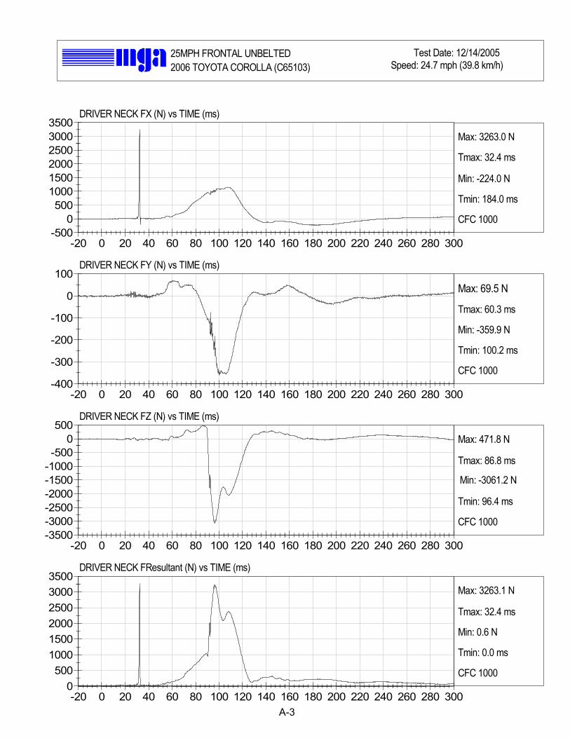
A-3
-20 0 20 40 60 80 100 120 140 160 180 200 220 240 260 280 300-500
0500
100015002000250030003500
-20 0 20 40 60 80 100 120 140 160 180 200 220 240 260 280 300-400
-300
-200
-100
0
100
-20 0 20 40 60 80 100 120 140 160 180 200 220 240 260 280 300-3500-3000-2500-2000-1500-1000-500
0500
-20 0 20 40 60 80 100 120 140 160 180 200 220 240 260 280 3000
500100015002000250030003500
25MPH FRONTAL UNBELTED Test Date: 12/14/2005Speed: 24.7 mph (39.8 km/h)2006 TOYOTA COROLLA (C65103)
Max: 3263.0 N
Tmax: 32.4 ms
Min: -224.0 N
Tmin: 184.0 ms
CFC 1000
DRIVER NECK FX (N) vs TIME (ms)
DRIVER NECK FY (N) vs TIME (ms)
Max: 69.5 N
Tmax: 60.3 ms
Min: -359.9 N
Tmin: 100.2 ms
CFC 1000
Max: 471.8 N
Tmax: 86.8 ms
Min: -3061.2 N
Tmin: 96.4 ms
CFC 1000
Max: 3263.1 N
Tmax: 32.4 ms
Min: 0.6 N
Tmin: 0.0 ms
CFC 1000
DRIVER NECK FZ (N) vs TIME (ms)
DRIVER NECK FResultant (N) vs TIME (ms)

A-4
-20 0 20 40 60 80 100 120 140 160 180 200 220 240 260 280 300-10-505
10152025
-20 0 20 40 60 80 100 120 140 160 180 200 220 240 260 280 300-40
-20
0
20
40
60
80
-20 0 20 40 60 80 100 120 140 160 180 200 220 240 260 280 300-20
-15
-10
-5
0
5
10
-20 0 20 40 60 80 100 120 140 160 180 200 220 240 260 280 3000
1020304050607080
25MPH FRONTAL UNBELTED Test Date: 12/14/2005Speed: 24.7 mph (39.8 km/h)2006 TOYOTA COROLLA (C65103)
Max: 23.1 Nm
Tmax: 108.3 ms
Min: -5.1 Nm
Tmin: 125.4 ms
CFC 600
DRIVER NECK MX (Nm) vs TIME (ms)
DRIVER NECK MY (Nm) vs TIME (ms)
Max: 72.2 Nm
Tmax: 110.3 ms
Min: -20.5 Nm
Tmin: 137.4 ms
CFC 600
Max: 9.2 Nm
Tmax: 182.9 ms
Min: -15.1 Nm
Tmin: 116.6 ms
CFC 600
Max: 76.5 Nm
Tmax: 110.0 ms
Min: 0.0 Nm
Tmin: 0.0 ms
CFC 600
DRIVER NECK MZ (Nm) vs TIME (ms)
DRIVER NECK MResultant (Nm) vs TIME (ms)

A-5
-20 0 20 40 60 80 100 120 140 160 180 200 220 240 260 280 300-35-30-25-20-15-10-505
-20 0 20 40 60 80 100 120 140 160 180 200 220 240 260 280 300-101234567
-20 0 20 40 60 80 100 120 140 160 180 200 220 240 260 280 300-10-505
10152025
-20 0 20 40 60 80 100 120 140 160 180 200 220 240 260 280 3000
10
20
30
40
50
25MPH FRONTAL UNBELTED Test Date: 12/14/2005Speed: 24.7 mph (39.8 km/h)2006 TOYOTA COROLLA (C65103)
Max: 1.5 G's
Tmax: 176.8 ms
Min: -33.2 G's
Tmin: 98.0 ms
CFC 180
DRIVER CHEST X (G's) vs TIME (ms)
DRIVER CHEST Y (G's) vs TIME (ms)
Max: 6.6 G's
Tmax: 98.3 ms
Min: -0.7 G's
Tmin: 129.0 ms
CFC 180
Max: 23.6 G's
Tmax: 95.3 ms
Min: -6.5 G's
Tmin: 63.6 ms
CFC 180
Max: 41.0 G's
Tmax: 95.9 ms
Min: 0.0 G's
Tmin: 0.0 ms
CFC 180
DRIVER CHEST Z (G's) vs TIME (ms)
DRIVER CHEST Resultant (G's) vs TIME (ms)

A-6
-20 0 20 40 60 80 100 120 140 160 180 200 220 240 260 280 300-20
-10
0
10
20
30
40
-20 0 20 40 60 80 100 120 140 160 180 200 220 240 260 280 300-101234567
-20 0 20 40 60 80 100 120 140 160 180 200 220 240 260 280 300-7.5
-5-2.5
02.5
57.510
12.5
-20 0 20 40 60 80 100 120 140 160 180 200 220 240 260 280 300-30-25-20-15-10-505
25MPH FRONTAL UNBELTED Test Date: 12/14/2005Speed: 24.7 mph (39.8 km/h)2006 TOYOTA COROLLA (C65103)
Max: 39.8 kph
Tmax: 0.0 ms
Min: -11.6 kph
Tmin: 153.1 ms
CFC 180
DRIVER CHEST X Velocity (kph) vs TIME (ms)
DRIVER CHEST Y Velocity (kph) vs TIME (ms)
Max: 7.0 kph
Tmax: 121.6 ms
Min: -0.0 kph
Tmin: 19.4 ms
CFC 180
Max: 12.2 kph
Tmax: 264.4 ms
Min: -5.8 kph
Tmin: 80.1 ms
CFC 180
Max: 0.1 mm
Tmax: 26.9 ms
Min: -29.3 mm
Tmin: 106.5 ms
CFC 600
DRIVER CHEST Z Velocity (kph) vs TIME (ms)
DRIVER CHEST DISPLACEMENT (mm) vs TIME (ms)

A-7
-20 0 20 40 60 80 100 120 140 160 180 200 220 240 260 280 300-4000-3500-3000-2500-2000-1500-1000-500
0500
-20 0 20 40 60 80 100 120 140 160 180 200 220 240 260 280 300-3500-3000-2500-2000-1500-1000-500
0500
25MPH FRONTAL UNBELTED Test Date: 12/14/2005Speed: 24.7 mph (39.8 km/h)2006 TOYOTA COROLLA (C65103)
Max: 272.4 N
Tmax: 253.9 ms
Min: -3649.1 N
Tmin: 74.0 ms
CFC 600
DRIVER LEFT FEMUR (N) vs TIME (ms)
DRIVER RIGHT FEMUR (N) vs TIME (ms)
Max: 196.9 N
Tmax: 25.1 ms
Min: -3466.2 N
Tmin: 63.8 ms
CFC 600

A-8
-20 0 20 40 60 80 100 120 140 160 180 200 220 240 260 280 300-40
-30
-20
-10
0
10
-20 0 20 40 60 80 100 120 140 160 180 200 220 240 260 280 300-30-25-20-15-10-505
10
-20 0 20 40 60 80 100 120 140 160 180 200 220 240 260 280 300-10-7.5
-5-2.5
02.5
57.510
12.5
-20 0 20 40 60 80 100 120 140 160 180 200 220 240 260 280 3000
10
20
30
40
50
25MPH FRONTAL UNBELTED Test Date: 12/14/2005Speed: 24.7 mph (39.8 km/h)2006 TOYOTA COROLLA (C65103)
Max: 2.9 G's
Tmax: 26.0 ms
Min: -37.8 G's
Tmin: 93.0 ms
CFC 1000
PASSENGER HEAD X (G's) vs TIME (ms)
PASSENGER HEAD Y (G's) vs TIME (ms)
Max: 7.8 G's
Tmax: 126.9 ms
Min: -25.7 G's
Tmin: 93.4 ms
CFC 1000
Max: 10.9 G's
Tmax: 91.7 ms
Min: -8.1 G's
Tmin: 95.9 ms
CFC 1000
Max: 46.5 G's
Tmax: 93.3 ms
Min: 0.0 G's
Tmin: 3.0 ms
CFC 1000
PASSENGER HEAD Z (G's) vs TIME (ms)
PASSENGER HEAD Resultant (G's) vs TIME (ms)

A-9
-20 0 20 40 60 80 100 120 140 160 180 200 220 240 260 280 300-10
0
10
20
30
40
50
-20 0 20 40 60 80 100 120 140 160 180 200 220 240 260 280 300-15
-12.5-10-7.5
-5-2.5
02.5
-20 0 20 40 60 80 100 120 140 160 180 200 220 240 260 280 300-1012345678
25MPH FRONTAL UNBELTED Test Date: 12/14/2005Speed: 24.7 mph (39.8 km/h)2006 TOYOTA COROLLA (C65103)
Max: 40.6 kph
Tmax: 50.6 ms
Min: -6.5 kph
Tmin: 259.7 ms
CFC 180
PASSENGER HEAD X Velocity (kph) vs TIME (ms)
PASSENGER HEAD Y Velocity (kph) vs TIME (ms)
Max: 0.2 kph
Tmax: 50.8 ms
Min: -15.0 kph
Tmin: 111.3 ms
CFC 180
Max: 7.5 kph
Tmax: 300.0 ms
Min: -0.5 kph
Tmin: 53.5 ms
CFC 180
PASSENGER HEAD Z Velocity (kph) vs TIME (ms)

A-10
-20 0 20 40 60 80 100 120 140 160 180 200 220 240 260 280 300-500
0
500
1000
1500
2000
-20 0 20 40 60 80 100 120 140 160 180 200 220 240 260 280 300-200
0
200
400
600
800
1000
-20 0 20 40 60 80 100 120 140 160 180 200 220 240 260 280 300-3000-2500-2000-1500-1000-500
0500
-20 0 20 40 60 80 100 120 140 160 180 200 220 240 260 280 3000
500100015002000250030003500
25MPH FRONTAL UNBELTED Test Date: 12/14/2005Speed: 24.7 mph (39.8 km/h)2006 TOYOTA COROLLA (C65103)
Max: 1862.5 N
Tmax: 85.3 ms
Min: -150.4 N
Tmin: 229.5 ms
CFC 1000
PASSENGER NECK FX (N) vs TIME (ms)
PASSENGER NECK FY (N) vs TIME (ms)
Max: 881.5 N
Tmax: 109.9 ms
Min: -73.0 N
Tmin: 245.9 ms
CFC 1000
Max: 159.0 N
Tmax: 173.3 ms
Min: -2892.4 N
Tmin: 94.1 ms
CFC 1000
Max: 3497.0 N
Tmax: 94.1 ms
Min: 0.5 N
Tmin: 0.0 ms
CFC 1000
PASSENGER NECK FZ (N) vs TIME (ms)
PASSENGER NECK FResultant (N) vs TIME (ms)

A-11
-20 0 20 40 60 80 100 120 140 160 180 200 220 240 260 280 300-20-15-10-505
10152025
-20 0 20 40 60 80 100 120 140 160 180 200 220 240 260 280 300-25
0255075
100125150175
-20 0 20 40 60 80 100 120 140 160 180 200 220 240 260 280 300-20
-10
0
10
20
30
40
-20 0 20 40 60 80 100 120 140 160 180 200 220 240 260 280 3000
255075
100125150175
25MPH FRONTAL UNBELTED Test Date: 12/14/2005Speed: 24.7 mph (39.8 km/h)2006 TOYOTA COROLLA (C65103)
Max: 21.1 Nm
Tmax: 152.6 ms
Min: -16.3 Nm
Tmin: 96.2 ms
CFC 600
PASSENGER NECK MX (Nm) vs TIME (ms)
PASSENGER NECK MY (Nm) vs TIME (ms)
Max: 151.3 Nm
Tmax: 84.3 ms
Min: -9.3 Nm
Tmin: 157.2 ms
CFC 600
Max: 37.4 Nm
Tmax: 117.8 ms
Min: -10.7 Nm
Tmin: 200.2 ms
CFC 600
Max: 152.8 Nm
Tmax: 94.8 ms
Min: 0.0 Nm
Tmin: 5.7 ms
CFC 600
PASSENGER NECK MZ (Nm) vs TIME (ms)
PASSENGER NECK MResultant (Nm) vs TIME (ms)

A-12
-20 0 20 40 60 80 100 120 140 160 180 200 220 240 260 280 300-25
-20
-15
-10
-5
0
5
-20 0 20 40 60 80 100 120 140 160 180 200 220 240 260 280 300-8
-6
-4
-2
0
2
4
-20 0 20 40 60 80 100 120 140 160 180 200 220 240 260 280 300-5
0
5
10
15
20
-20 0 20 40 60 80 100 120 140 160 180 200 220 240 260 280 3000
5
10
15
20
25
25MPH FRONTAL UNBELTED Test Date: 12/14/2005Speed: 24.7 mph (39.8 km/h)2006 TOYOTA COROLLA (C65103)
Max: 1.9 G's
Tmax: 218.0 ms
Min: -23.4 G's
Tmin: 85.7 ms
CFC 180
PASSENGER CHEST X (G's) vs TIME (ms)
PASSENGER CHEST Y (G's) vs TIME (ms)
Max: 3.1 G's
Tmax: 55.1 ms
Min: -6.9 G's
Tmin: 108.9 ms
CFC 180
Max: 15.7 G's
Tmax: 94.4 ms
Min: -4.6 G's
Tmin: 53.6 ms
CFC 180
Max: 24.9 G's
Tmax: 85.7 ms
Min: 0.0 G's
Tmin: 0.0 ms
CFC 180
PASSENGER CHEST Z (G's) vs TIME (ms)
PASSENGER CHEST Resultant (G's) vs TIME (ms)

A-13
-20 0 20 40 60 80 100 120 140 160 180 200 220 240 260 280 300-10
0
10
20
30
40
-20 0 20 40 60 80 100 120 140 160 180 200 220 240 260 280 300-10
-8
-6 -4 -2 0
2
-20 0 20 40 60 80 100 120 140 160 180 200 220 240 260 280 300-2.5
0 2.5
5 7.5 10
12.5 15
17.5
-20 0 20 40 60 80 100 120 140 160 180 200 220 240 260 280 300-10
-8 -6
-4 -2 0 2
25MPH FRONTAL UNBELTED Test Date: 12/14/2005Speed: 24.7 mph (39.8 km/h)2006 TOYOTA COROLLA (C65103)
Max: 39.8 kph
Tmax: 6.2 ms
Min: -0.5 kph
Tmin: 143.7 ms
CFC 180
PASSENGER CHEST X Velocity (kph) vs TIME (ms)
PASSENGER CHEST Y Velocity (kph) vs TIME (ms)
Max: 0.6 kph
Tmax: 61.1 ms
Min: -8.5 kph
Tmin: 200.5 ms
CFC 180
Max: 16.4 kph
Tmax: 300.0 ms
Min: -2.2 kph
Tmin: 70.4 ms
CFC 180
Max: 0.6 mm
Tmax: 49.8 ms
Min: -8.49 mm
Tmin: 96.2 ms
CFC 600
PASSENGER CHEST Z Velocity (kph) vs TIME (ms)
PASSENGER CHEST DISPLACEMENT (mm) vs TIME (ms)

A-14
-20 0 20 40 60 80 100 120 140 160 180 200 220 240 260 280 300-5000
-4000
-3000
-2000
-1000
0
1000
-20 0 20 40 60 80 100 120 140 160 180 200 220 240 260 280 300-3500-3000-2500-2000-1500-1000-500
0500
25MPH FRONTAL UNBELTED Test Date: 12/14/2005Speed: 24.7 mph (39.8 km/h)2006 TOYOTA COROLLA (C65103)
Max: 161.0 N
Tmax: 227.0 ms
Min: -4402.9 N
Tmin: 53.8 ms
CFC 600
PASSENGER LEFT FEMUR (N) vs TIME (ms)
PASSENGER RIGHT FEMUR (N) vs TIME (ms)
Max: 271.4 N
Tmax: 170.7 ms
Min: -3464.0 N
Tmin: 97.2 ms
CFC 600

A-15
-20 0 20 40 60 80 100 120 140 160 180 200 220 240 260 280 3000
0.05
0.1
0.15
0.2
0.25
-20 0 20 40 60 80 100 120 140 160 180 200 220 240 260 280 3000
0.0250.05
0.0750.1
0.1250.15
0.175
-20 0 20 40 60 80 100 120 140 160 180 200 220 240 260 280 3000
0.10.20.30.40.50.60.7
-20 0 20 40 60 80 100 120 140 160 180 200 220 240 260 280 3000
0.1
0.2
0.3
0.4
0.5
25MPH FRONTAL UNBELTED Test Date: 12/14/2005Speed: 24.7 mph (39.8 km/h)2006 TOYOTA COROLLA (C65103)
Max: 0.2
Tmax: 89.0 ms
Min: 0.0
Tmin: 0.0 ms
CFC 600
Drv. nij (NTF) () vs TIME (ms)
Drv. nij (NTE) () vs TIME (ms)
Max: 0.2
Tmax: 137.4 ms
Min: 0.0
Tmin: 0.0 ms
CFC 600
Max: 0.7
Tmax: 96.3 ms
Min: 0.0
Tmin: 0.0 ms
CFC 600
Max: 0.4
Tmax: 32.3 ms
Min: 0.0
Tmin: 0.0 ms
CFC 600
Drv. nij (NCF) () vs TIME (ms)
Drv. nij (NCE) () vs TIME (ms)

A-16
-20 0 20 40 60 80 100 120 140 160 180 200 220 240 260 280 3000
0.01
0.02
0.03
0.04
0.05
0.06
-20 0 20 40 60 80 100 120 140 160 180 200 220 240 260 280 3000
0.01
0.02
0.03
0.04
0.05
0.06
-20 0 20 40 60 80 100 120 140 160 180 200 220 240 260 280 3000
0.2
0.4
0.6
0.8
1
-20 0 20 40 60 80 100 120 140 160 180 200 220 240 260 280 3000
0.0250.05
0.0750.1
0.1250.15
0.175
25MPH FRONTAL UNBELTED Test Date: 12/14/2005Speed: 24.7 mph (39.8 km/h)2006 TOYOTA COROLLA (C65103)
Max: 0.1
Tmax: 212.0 ms
Min: 0.0
Tmin: 0.0 ms
CFC 600
Pass. nij (NTF) () vs TIME (ms)
Pass. nij (NTE) () vs TIME (ms)
Max: 0.1
Tmax: 172.4 ms
Min: 0.0
Tmin: 0.0 ms
CFC 600
Max: 0.8
Tmax: 94.2 ms
Min: 0.0
Tmin: 0.0 ms
CFC 600
Max: 0.2
Tmax: 152.9 ms
Min: 0.0
Tmin: 0.0 ms
CFC 600
Pass. nij (NCF) () vs TIME (ms)
Pass. nij (NCE) () vs TIME (ms)

A-17
-20 0 20 40 60 80 100 120 140 160 180 200 220 240 260 280 300-75
-50
-25
0
25
50
75
-20 0 20 40 60 80 100 120 140 160 180 200 220 240 260 280 300-25
0
25
50
75
100
125
25MPH FRONTAL UNBELTED Test Date: 12/14/2005Speed: 24.7 mph (39.8 km/h)2006 TOYOTA COROLLA (C65103)
Max: 53.9 Nm
Tmax: 93.2 ms
Min: -55.2 Nm
Tmin: 32.3 ms
CFC 600
Drv. Occipital Condyle Moment (Nm) vs TIME (ms)
Pass. Occipital Condyle Moment (Nm) vs TIME (ms)
Max: 118.2 Nm
Tmax: 84.3 ms
Min: -10.7 Nm
Tmin: 156.0 ms
CFC 600
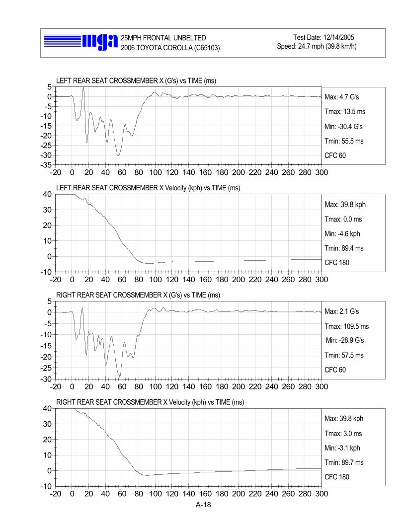
A-18
-20 0 20 40 60 80 100 120 140 160 180 200 220 240 260 280 300-35-30-25-20-15-10-505
-20 0 20 40 60 80 100 120 140 160 180 200 220 240 260 280 300-10
0
10
20
30
40
-20 0 20 40 60 80 100 120 140 160 180 200 220 240 260 280 300-30-25-20-15-10-505
-20 0 20 40 60 80 100 120 140 160 180 200 220 240 260 280 300-10
0
10
20
30
40
25MPH FRONTAL UNBELTED Test Date: 12/14/2005Speed: 24.7 mph (39.8 km/h)2006 TOYOTA COROLLA (C65103)
Max: 4.7 G's
Tmax: 13.5 ms
Min: -30.4 G's
Tmin: 55.5 ms
CFC 60
LEFT REAR SEAT CROSSMEMBER X (G's) vs TIME (ms)
LEFT REAR SEAT CROSSMEMBER X Velocity (kph) vs TIME (ms)
Max: 39.8 kph
Tmax: 0.0 ms
Min: -4.6 kph
Tmin: 89.4 ms
CFC 180
Max: 2.1 G's
Tmax: 109.5 ms
Min: -28.9 G's
Tmin: 57.5 ms
CFC 60
Max: 39.8 kph
Tmax: 3.0 ms
Min: -3.1 kph
Tmin: 89.7 ms
CFC 180
RIGHT REAR SEAT CROSSMEMBER X (G's) vs TIME (ms)
RIGHT REAR SEAT CROSSMEMBER X Velocity (kph) vs TIME (ms)

A-19
-20 0 20 40 60 80 100 120 140 160 180 200 220 240 260 280 300-40
-30
-20
-10
0
10
20
-20 0 20 40 60 80 100 120 140 160 180 200 220 240 260 280 300-10
0
10
20
30
40
-20 0 20 40 60 80 100 120 140 160 180 200 220 240 260 280 300-75
-50
-25
0
25
50
-20 0 20 40 60 80 100 120 140 160 180 200 220 240 260 280 300-10
0
10
20
30
40
25MPH FRONTAL UNBELTED Test Date: 12/14/2005Speed: 24.7 mph (39.8 km/h)2006 TOYOTA COROLLA (C65103)
Max: 11.9 G's
Tmax: 64.2 ms
Min: -40.0 G's
Tmin: 44.3 ms
CFC 60
TOP OF ENGINE X (G's) vs TIME (ms)
TOP OF ENGINE X Velocity (kph) vs TIME (ms)
Max: 39.8 kph
Tmax: 0.0 ms
Min: -5.0 kph
Tmin: 162.1 ms
CFC 180
Max: 38.5 G's
Tmax: 53.4 ms
Min: -62.3 G's
Tmin: 44.3 ms
CFC 60
Max: 39.8 kph
Tmax: 0.0 ms
Min: -2.5 kph
Tmin: 300.0 ms
CFC 180
BOTTOM OF ENGINE X (G's) vs TIME (ms)
BOTTOM OF ENGINE X Velocity (kph) vs TIME (ms)
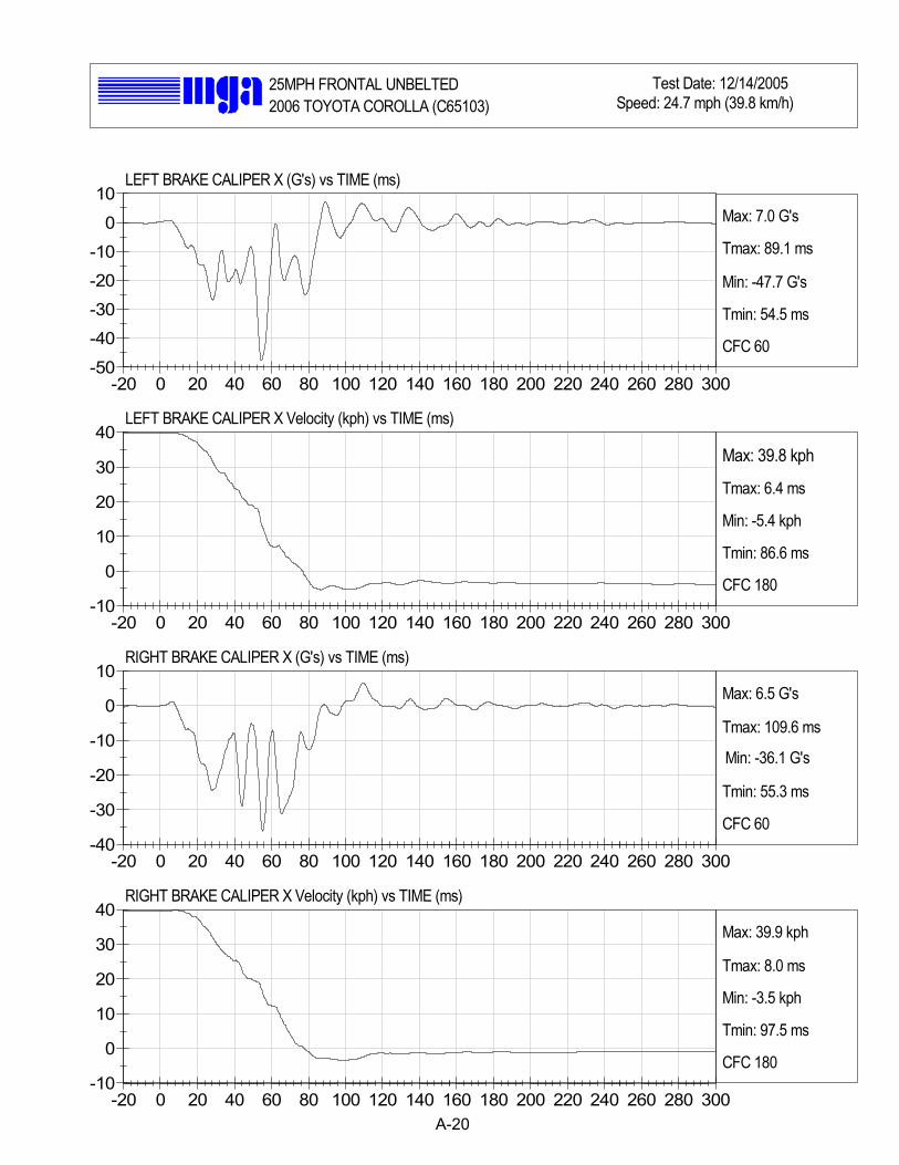
A-20
-20 0 20 40 60 80 100 120 140 160 180 200 220 240 260 280 300-50
-40
-30
-20
-10
0
10
-20 0 20 40 60 80 100 120 140 160 180 200 220 240 260 280 300-10
0
10
20
30
40
-20 0 20 40 60 80 100 120 140 160 180 200 220 240 260 280 300-40
-30
-20
-10
0
10
-20 0 20 40 60 80 100 120 140 160 180 200 220 240 260 280 300-10
0
10
20
30
40
25MPH FRONTAL UNBELTED Test Date: 12/14/2005Speed: 24.7 mph (39.8 km/h)2006 TOYOTA COROLLA (C65103)
Max: 7.0 G's
Tmax: 89.1 ms
Min: -47.7 G's
Tmin: 54.5 ms
CFC 60
LEFT BRAKE CALIPER X (G's) vs TIME (ms)
LEFT BRAKE CALIPER X Velocity (kph) vs TIME (ms)
Max: 39.8 kph
Tmax: 6.4 ms
Min: -5.4 kph
Tmin: 86.6 ms
CFC 180
Max: 6.5 G's
Tmax: 109.6 ms
Min: -36.1 G's
Tmin: 55.3 ms
CFC 60
Max: 39.9 kph
Tmax: 8.0 ms
Min: -3.5 kph
Tmin: 97.5 ms
CFC 180
RIGHT BRAKE CALIPER X (G's) vs TIME (ms)
RIGHT BRAKE CALIPER X Velocity (kph) vs TIME (ms)

A-21
-20 0 20 40 60 80 100 120 140 160 180 200 220 240 260 280 300-80
-60
-40
-20
0
20
40
-20 0 20 40 60 80 100 120 140 160 180 200 220 240 260 280 300-10
0
10
20
30
40
-20 0 20 40 60 80 100 120 140 160 180 200 220 240 260 280 300-20-15-10-505
1015
-20 0 20 40 60 80 100 120 140 160 180 200 220 240 260 280 300-1.5
-1-0.5
00.5
11.5
2
25MPH FRONTAL UNBELTED Test Date: 12/14/2005Speed: 24.7 mph (39.8 km/h)2006 TOYOTA COROLLA (C65103)
Max: 24.2 G's
Tmax: 40.8 ms
Min: -68.7 G's
Tmin: 25.3 ms
CFC 60
INSTRUMENT PANEL X (G's) vs TIME (ms)
INSTRUMENT PANEL X Velocity (kph) vs TIME (ms)
Max: 39.8 kph
Tmax: 0.0 ms
Min: -6.8 kph
Tmin: 121.3 ms
CFC 180
Max: 12.0 G's
Tmax: 21.6 ms
Min: -15.2 G's
Tmin: 17.5 ms
CFC 60
Max: 1.9 kph
Tmax: 300.0 ms
Min: -1.4 kph
Tmin: 19.3 ms
CFC 180
TRUNK Z (G's) vs TIME (ms)
TRUNK Z Velocity (kph) vs TIME (ms)

APPENDIX B
CRASH TEST PHOTOGRAPHS

TABLE OF PHOTOGRAPHS
Page No.
Photo No. 1. Vehicle Certification Label B-1
Photo No. 2. Tire Placard B-2
Photo No. 3. Pre-Test Front View of Test Vehicle B-3
Photo No. 4. Post-Test Front View of Test Vehicle B-4
Photo No. 5. Pre-Test Left Side View of Test Vehicle B-5
Photo No. 6. Post-Test Left Side View of Test Vehicle B-6
Photo No. 7. Pre-Test Right Side View of Test Vehicle B-7
Photo No. 8. Post-Test Right Side View of Test Vehicle B-8
Photo No. 9. Pre-Test Right Front Three-Quarter View of Test Vehicle B-9
Photo No. 10. Post-Test Right Front Three-Quarter View of Test Vehicle B-10
Photo No. 11. Pre-Test Left Front Three-Quarter View of Test Vehicle B-11
Photo No. 12. Post-Test Left Front Three-Quarter View of Test Vehicle B-12
Photo No. 13. Pre-Test Right Rear Three-Quarter View of Test Vehicle B-13
Photo No. 14. Post-Test Right Rear Three-Quarter View of Test Vehicle B-14
Photo No. 15. Pre-Test Left Rear Three-Quarter View of Test Vehicle B-15
Photo No. 16. Post-Test Left Rear Three-Quarter View of Test Vehicle B-16
Photo No. 17. Pre-Test Rear View of Test Vehicle B-17
Photo No. 18. Post-Test Rear View of Test Vehicle B-18
Photo No. 19. Pre-Test Windshield View B-19
Photo No. 20. Post-Test Windshield View B-20
Photo No. 21. Pre-Test Engine Compartment View B-21
Photo No. 22. Post-Test Engine Compartment View B-22
Photo No. 23. Pre-Test Fuel Filler Cap View B-23
Photo No. 24. Pre-Test Front Underbody View B-24
Photo No. 25. Post-Test Front Underbody View B-25
Photo No. 26. Pre-Test Mid Underbody View B-26

Page No.
Photo No. 27. Post-Test Mid Underbody View B-27
Photo No. 28. Pre-Test Mid Rear Underbody View B-28
Photo No. 29. Pre-Test Rear Underbody View B-29
Photo No. 30. Post-Test Rear Underbody View B-30
Photo No. 31. Pre-Test Driver Dummy Front View (head position) B-31
Photo No. 32. Post-Test Driver Dummy Front View (head position) B-32
Photo No. 33. Pre-Test Driver Dummy Position Left Side View B-33
Photo No. 34. Post-Test Driver Dummy Position Left Side View B-34
Photo No. 35. Pre-Test Driver Dummy Position Left Side View (Door Open) B-35
Photo No. 36. Post-Test Driver Dummy Position Left Side View (Door Open) B-36
Photo No. 37. Pre-Test Driver Dummy Seat Position B-37
Photo No. 38. Post-Test Driver Dummy Seat Position B-38
Photo No. 39. Pre-Test Driver Dummy Feet Position B-39
Photo No. 40. Post-Test Driver Dummy Feet Position B-40
Photo No. 41. Pre-Test Driver Side Knee Bolster View B-41
Photo No. 42. Post-Test Driver Side Knee Bolster View B-42
Photo No. 43. Post-Test Driver Dummy Head Contact (headrest) B-43
Photo No. 44. Post-Test Driver Dummy Head Contact (windshield) B-44
Photo No. 45. Post-Test Driver Dummy Knee Contact B-45
Photo No. 46. Post-Test Driver Dummy Airbag Contact B-46
Photo No. 47. Pre-Test Passenger Dummy Front View (head position) B-47
Photo No. 48. Post-Test Passenger Dummy Front View (head position) B-48
Photo No. 49. Pre-Test Passenger Dummy Position Right Side View B-49
Photo No. 50. Post-Test Passenger Dummy Position Right Side View B-50
Photo No. 51. Pre-Test Passenger Dummy Position Right Side View (Door Open) B-51
Photo No. 52. Post-Test Passenger Dummy Position Right Side View (Door Open) B-52
Photo No. 53. Pre-Test Passenger Dummy Seat Position B-53
Photo No. 54. Post-Test Passenger Dummy Seat Position B-54

Page No.
Photo No. 55. Pre-Test Passenger Dummy Feet Position B-55
Photo No. 56. Post-Test Passenger Dummy Feet Position B-56
Photo No. 57. Pre-Test Passenger Side Knee Bolster View B-57
Photo No. 58. Post-Test Passenger Side Knee Bolster View 1 B-58
Photo No. 59. Post-Test Passenger Side Knee Bolster View 2 B-59
Photo No. 60. Post-Test Passenger Dummy Head Contact View (visor) B-60
Photo No. 61. Post-Test Passenger Dummy Knee Contact B-61
Photo No. 62. Post-Test Passenger Dummy Airbag Contact B-62
Photo No. 63. Vehicle Impact B-63
Photo No. 64. Temperature Plot B-64

1
Vehicle Certification Label
B-1
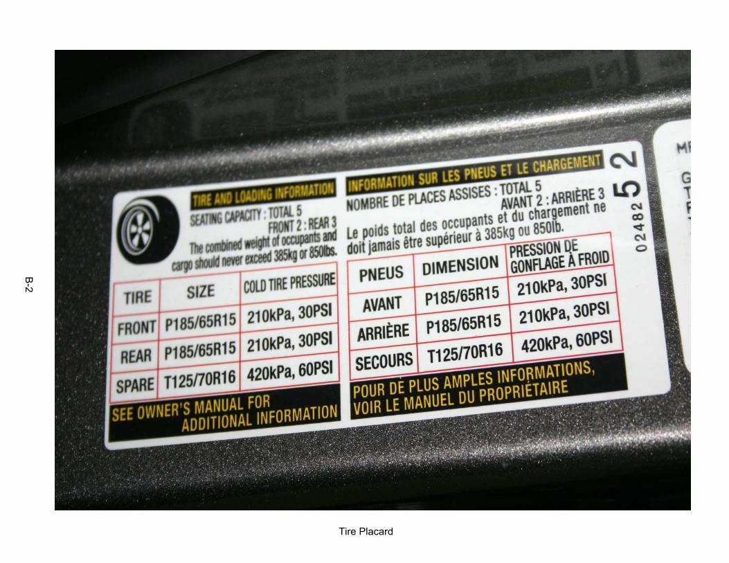
2
Tire Placard
B-2

3
Pre-Test Front View of Test Vehicle
B-3

4
Post-Test Front View of Test Vehicle
B-4

5
Pre-Test Left Side View of Test Vehicle
B-5

6
Post-Test Left Side View of Test Vehicle
B-6

7
Pre-Test Right Side View of Test Vehicle
B-7

8
Post-Test Right Side View of Test Vehicle
B-8
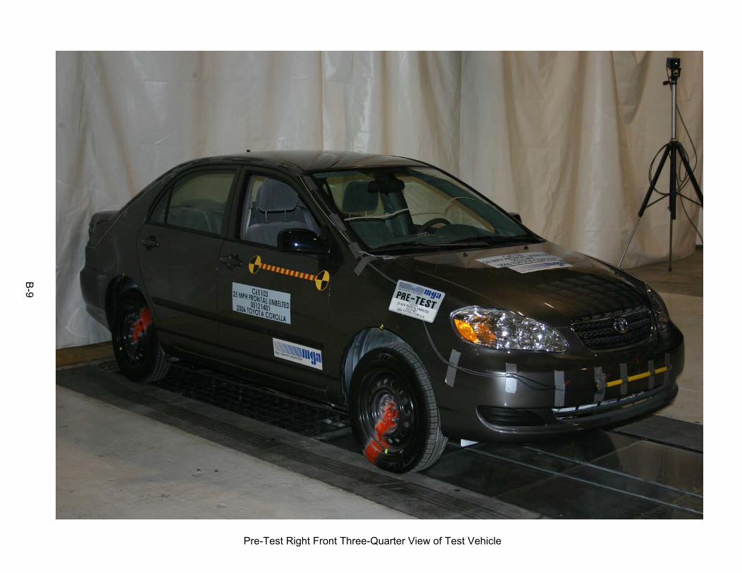
9
Pre-Test Right Front Three-Quarter View of Test Vehicle
B-9

10
Post-Test Right Front Three-Quarter View of Test Vehicle
B-10

11
Pre-Test Left Front Three-Quarter View of Test Vehicle
B-11

12
Post-Test Left Front Three-Quarter View of Test Vehicle
B-12

13
Pre-Test Right Rear Three-Quarter View of Test Vehicle
B-13

14
Post-Test Right Rear Three-Quarter View of Test Vehicle
B-14

15
Pre-Test Left Rear Three-Quarter View of Test Vehicle
B-15

16
Post-Test Left Rear Three-Quarter View of Test Vehicle
B-16

17
Pre-Test Rear View of Test Vehicle
B-17

18
Post-Test Rear View of Test Vehicle
B-18

19
Pre-Test Windshield View
B-19

20
Post-Test Windshield View
B-20

21
Pre-Test Engine Compartment View
B-21

22
Post-Test Engine Compartment View
B-22

23
Pre-Test Fuel Filler Cap View
B-23

24
Pre-Test Front Underbody View
B-24

25
Post-Test Front Underbody View
B-25

26
Pre-Test Mid Underbody View
B-26

27
Post-Test Mid Underbody View
B-27

28
Pre-Test Mid Rear Underbody View
B-28

29
Pre-Test Rear Underbody View
B-29

30
Post-Test Rear Underbody View
B-30

31
Pre-Test Driver Dummy Front View (head position)
B-31

32
Post-Test Driver Dummy Front View (head position)
B-32

33
Pre-Test Driver Dummy Position Left Side View
B-33

34
Post-Test Driver Dummy Position Left Side View
B-34

35
Pre-Test Driver Dummy Position Left Side View (Door Open)
B-35
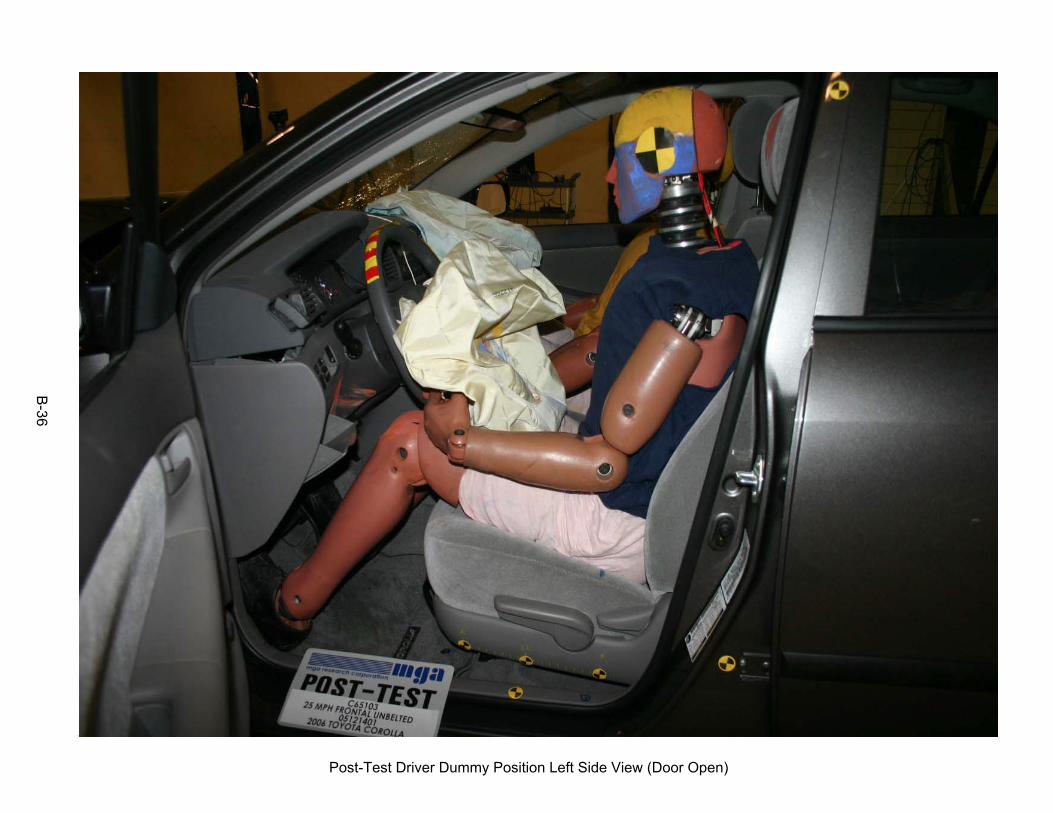
36
Post-Test Driver Dummy Position Left Side View (Door Open)
B-36

37
Pre-Test Driver Dummy Seat Position
B-37
38
Post-Test Driver Dummy Seat Position
B-38

39
Pre-Test Driver Dummy Feet Position
B-39

40
Post-Test Driver Dummy Feet Position
B-40

41
Pre-Test Driver Side Knee Bolster View
B-41
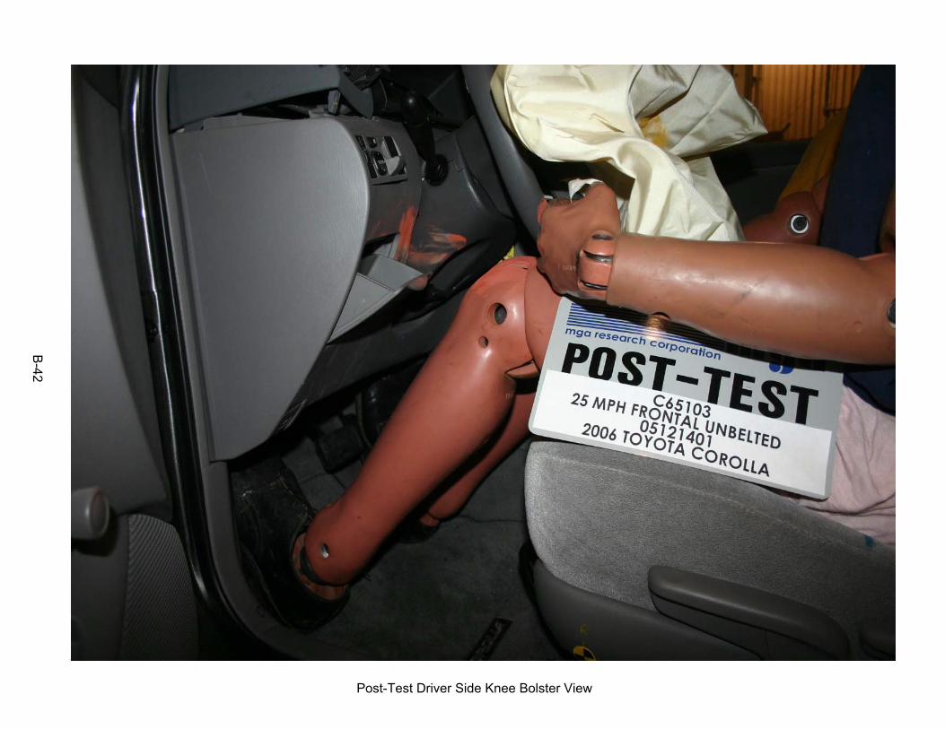
42
Post-Test Driver Side Knee Bolster View
B-42

43
Post-Test Driver Dummy Head Contact (headrest)
B-43

44
Post-Test Driver Dummy Head Contact (windshield)
B-44

45
Post-Test Driver Dummy Knee Contact
B-45
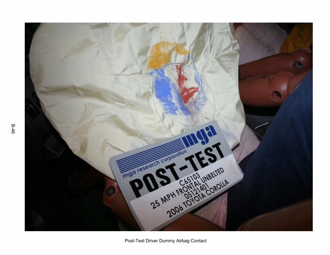
46
Post-Test Driver Dummy Airbag Contact
B-46

47
Pre-Test Passenger Dummy Front View (head position)
B-47

48
Post-Test Passenger Dummy Front View (head position)
B-48

49
Pre-Test Passenger Dummy Position Right Side View
B-49

50
Post-Test Passenger Dummy Position Right Side View
B-50

51
Pre-Test Passenger Dummy Position Right Side View (Door Open)
B-51
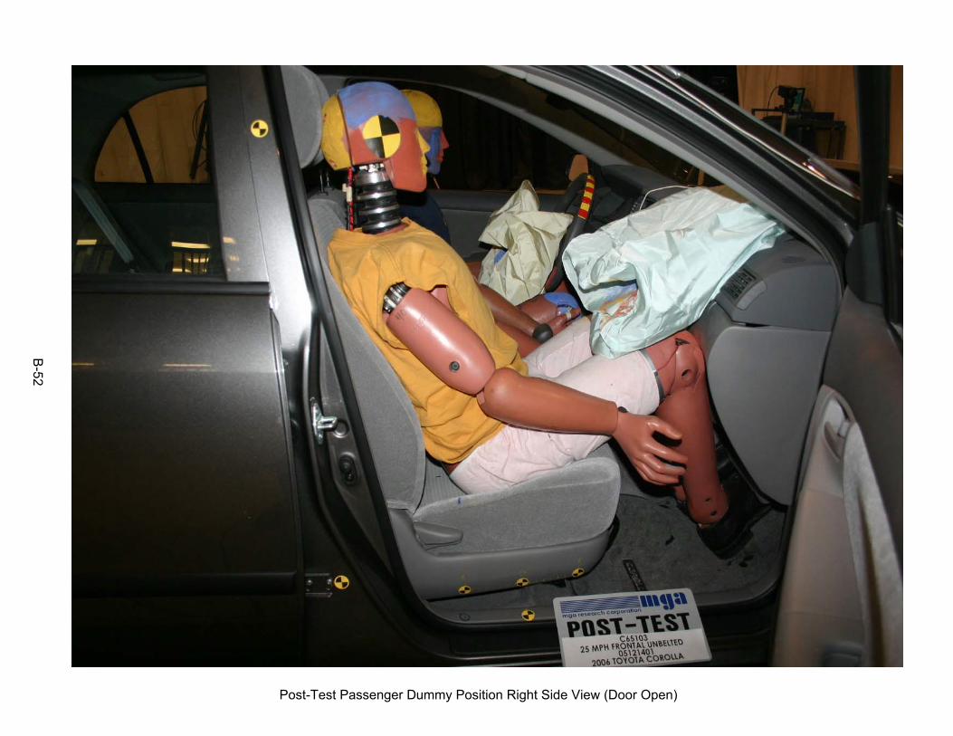
52
Post-Test Passenger Dummy Position Right Side View (Door Open)
B-52

53
Pre-Test Passenger Dummy Seat Position
B-53

54
Post-Test Passenger Dummy Seat Position
B-54

55
Pre-Test Passenger Dummy Feet Position
B-55

56
Post-Test Passenger Dummy Feet Position
B-56

57
Pre-Test Passenger Side Knee Bolster View
B-57

58
Post-Test Passenger Side Knee Bolster View 1
B-58

59
Post-Test Passenger Side Knee Bolster View 2
B-59

60
Post-Test Passenger Dummy Head Contact View (visor)
B-60

61
Post-Test Passenger Dummy Knee Contact
B-61

62
Post-Test Passenger Dummy Airbag Contact
B-62

63
Vehicle Impact
B-63

64
Temperature Plot
B-64

APPENDIX C
INSTRUMENTATION CALIBRATION
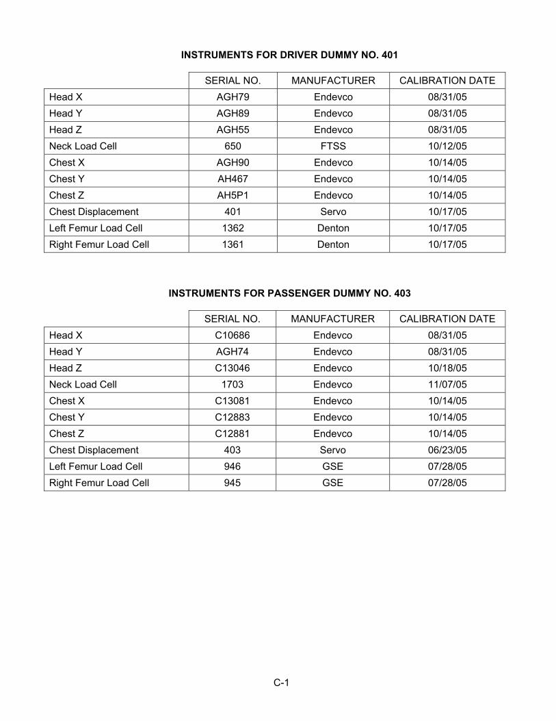
C-1
INSTRUMENTS FOR DRIVER DUMMY NO. 401 SERIAL NO. MANUFACTURER CALIBRATION DATE Head X AGH79 Endevco 08/31/05 Head Y AGH89 Endevco 08/31/05 Head Z AGH55 Endevco 08/31/05 Neck Load Cell 650 FTSS 10/12/05 Chest X AGH90 Endevco 10/14/05 Chest Y AH467 Endevco 10/14/05 Chest Z AH5P1 Endevco 10/14/05 Chest Displacement 401 Servo 10/17/05 Left Femur Load Cell 1362 Denton 10/17/05 Right Femur Load Cell 1361 Denton 10/17/05
INSTRUMENTS FOR PASSENGER DUMMY NO. 403 SERIAL NO. MANUFACTURER CALIBRATION DATE Head X C10686 Endevco 08/31/05 Head Y AGH74 Endevco 08/31/05 Head Z C13046 Endevco 10/18/05 Neck Load Cell 1703 Endevco 11/07/05 Chest X C13081 Endevco 10/14/05 Chest Y C12883 Endevco 10/14/05 Chest Z C12881 Endevco 10/14/05 Chest Displacement 403 Servo 06/23/05 Left Femur Load Cell 946 GSE 07/28/05 Right Femur Load Cell 945 GSE 07/28/05

C-2
VEHICLE INSTRUMENTS SERIAL NO. MANUFACTURER CALIBRATION DATE Left Rear Seat Crossmember X C15-L21 Entran 10/18/05 Right Rear Seat Crossmember X F29-X01 Entran 07/26/05 Top of Engine X P22696 Endevco 08/15/05 Bottom of Engine X B19-Z04 Entran 09/29/05 Left Brake Caliper X F04-R23 Entran 09/29/05 Right Brake Caliper X B19-Z03 Entran 09/29/05 Instrument Panel X E05-Z22 Entran 07/19/05 Trunk Z D03-Z17 Entran 10/17/05

APPENDIX D
H POINT ATD POSITIONING CCM DATA

D-1
DRIVER CCM DATA
TOYOTA COROLLA C65103 12-14-05 TEST DATE
Driver Hpt Oscar Data 12-13-05
Index Xmm Ymm Zmm H Pt
0002 +00198.534 -00206.587 -00227.708 Sill
0003 +00209.290 -00057.947 -00414.530 Hinge
0006 +00905.943 -00022.114 -00090.383 Striker
0001 -00000.325 -00000.052 -00000.095 Dash
0005 +00724.120 -00157.132 -00098.539 Header
0004 +00188.679 -00235.485 +00536.626
Driver Dummy Data 12-14-05 Index Xmm Ymm Zmm
H pt 0004 +00204.285 -00139.330 -00244.831
Striker 0001 -00000.222 -00000.234 +00000.151
From APPENDIX F
DUMMY POSITIONING PROCEDURES FOR DRIVER TEST DUMMY CONFORMING TO SUBPART E OF PART 572
Previous to neck adjustment X 12. Position the H-point of the dummy within 0.5 inch of the vertical dimension and 0.5 inch of the
horizontal dimension of a point 0.25 inch below the H-point determined by using the equipment and procedures specified in SAE J826 (APR 1980). (S10.4.2.1) Then measure the pelvic angle with respect to the horizontal using the pelvic angle gage.
Adjust the dummy position until these three measurements are within the specifications. (S10.4.2.1 and S10.4.2.2)
.270 horizontal inches from the point 0.25 below the determined H-point (0.5 inch max.) (S10.4.2.1) .030 vertical inches from the point 0.25 below the determined H-point (0.5 inch max.) (S10.4.2.1) 24.8° pelvic angle (20o to 25o) After neck adjustment of one notch X 13.5 Adjust the neck bracket of the dummy the minimum amount necessary from the non-adjusted “0”
setting until the head is level within ± 0.5o. (S10.1) Record the following, then go to 14 (The neck bracket was moved one notch)
.226 horizontal inches from the point 0.25 below the determined H-point (0.5 inch max.) (S10.4.2.1) 5.751 mm = .226 inches FORWARD .438 vertical inches from the point 0.25 below the determined H-point (0.5 inch max.) (S10.4.2.1) 11.123 mm = .438 inches BELOW 22.5° pelvic angle (20o to 25o)
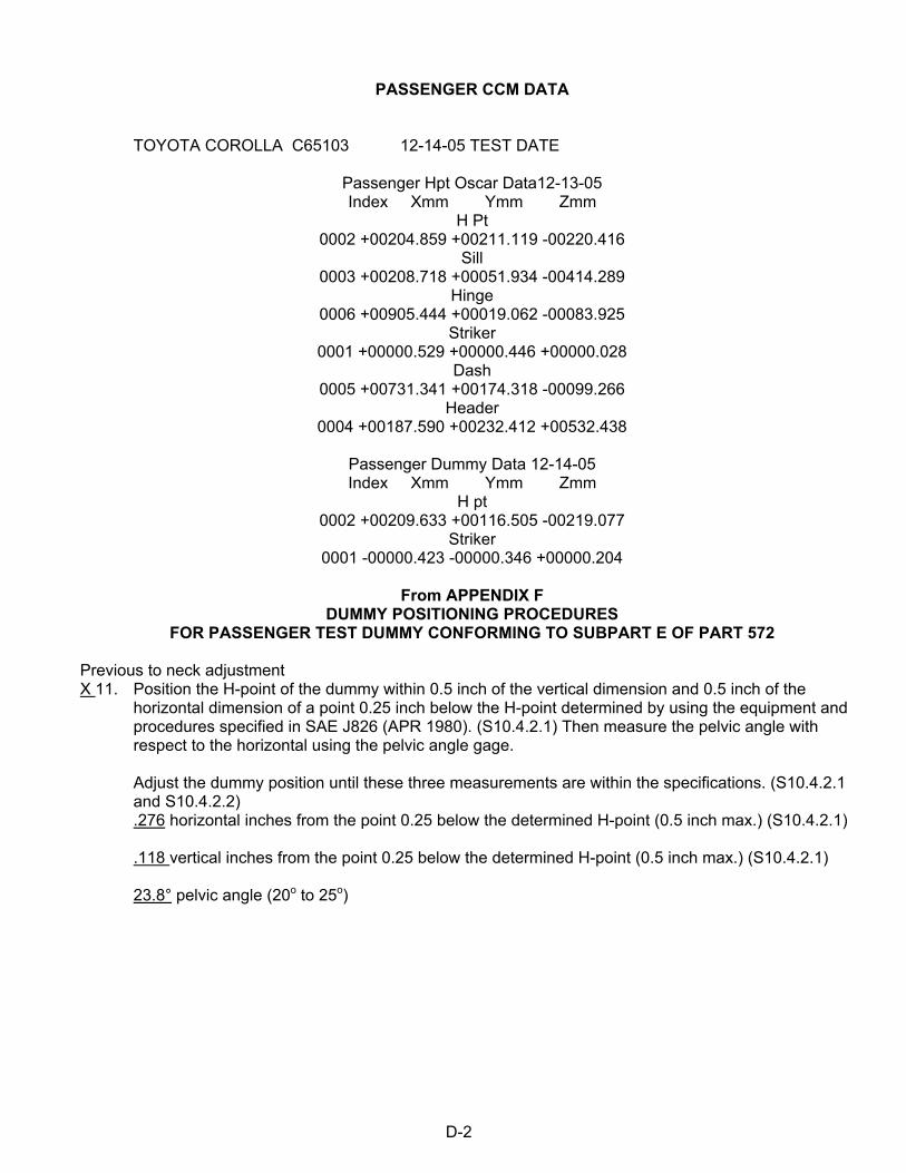
D-2
PASSENGER CCM DATA
TOYOTA COROLLA C65103 12-14-05 TEST DATE
Passenger Hpt Oscar Data12-13-05 Index Xmm Ymm Zmm
H Pt 0002 +00204.859 +00211.119 -00220.416
Sill 0003 +00208.718 +00051.934 -00414.289
Hinge 0006 +00905.444 +00019.062 -00083.925
Striker 0001 +00000.529 +00000.446 +00000.028
Dash 0005 +00731.341 +00174.318 -00099.266
Header 0004 +00187.590 +00232.412 +00532.438
Passenger Dummy Data 12-14-05 Index Xmm Ymm Zmm
H pt 0002 +00209.633 +00116.505 -00219.077
Striker 0001 -00000.423 -00000.346 +00000.204
From APPENDIX F
DUMMY POSITIONING PROCEDURES FOR PASSENGER TEST DUMMY CONFORMING TO SUBPART E OF PART 572
Previous to neck adjustment X 11. Position the H-point of the dummy within 0.5 inch of the vertical dimension and 0.5 inch of the
horizontal dimension of a point 0.25 inch below the H-point determined by using the equipment and procedures specified in SAE J826 (APR 1980). (S10.4.2.1) Then measure the pelvic angle with respect to the horizontal using the pelvic angle gage.
Adjust the dummy position until these three measurements are within the specifications. (S10.4.2.1 and S10.4.2.2)
.276 horizontal inches from the point 0.25 below the determined H-point (0.5 inch max.) (S10.4.2.1) .118 vertical inches from the point 0.25 below the determined H-point (0.5 inch max.) (S10.4.2.1) 23.8° pelvic angle (20o to 25o)

D-3
PASSENGER CCM DATA (Continued….)
From APPENDIX F DUMMY POSITIONING PROCEDURES
FOR PASSENGER TEST DUMMY CONFORMING TO SUBPART E OF PART 572
After neck adjustment of four notches X 12.5 Adjust the neck bracket of the dummy the minimum amount necessary from the non-adjusted “0”
setting until the head is level within ± 0.5o. (S10.1)
Record the following, then go to 13 (The neck bracket was moved four notches) .188 horizontal inches from the point 0.25 below the determined H-point (0.5 inch max.) (S10.4.2.1) 4.774 mm = .188 inches FORWARD .289 vertical inches from the point 0.25 below the determined H-point (0.5 inch max.) (S10.4.2.1) 7.339 mm = .289 inches ABOVE 23.4°pelvic angle (20o to 25o) (S10.4.2.2)

![Animalsekladata.com/_jLM27dZk4eKuErpqWbtwqmQr1M/anglais_lecons... · 2016-12-20 · Body parts HEAD NECK SHOULDERS ARM [hed] [nek] [ˈʃəʊldəɼz] [ɑːm] HAND CHEST BACK HIP](https://img.pdfslide.us/doc/110x75/5f8da54e81650a52fd3e31c9/2016-12-20-body-parts-head-neck-shoulders-arm-hed-nek-fldz-m.jpg)

![Sternalis muscle: an underestimated anterior chest wall … · 2017. 3. 23. · used as a muscle flap in anterior chest wall, head and neck, and breast reconstruction [17,24]. Conclusion](https://img.pdfslide.us/doc/110x75/61041e928c8eb964ef424e6a/sternalis-muscle-an-underestimated-anterior-chest-wall-2017-3-23-used-as-a.jpg)