Embed Size (px)
Citation preview
Foreword
Welcome to the growing group of value- conscious people who drive Toyotas. We areproud of the advanced engineering and quality construction of each vehicle we build.
This Owner’s Manual explains the features of your new Toyota. Please read it and followthe instructions carefully so that you can enjoy many years of safe motoring.
When it comes to service, remember that your Toyota dealer knows your vehicle bestand is interested in your complete satisfaction. He will provide quality maintenance andany other assistance you may require.
Please leave this Owner’s Manual in this vehicle at the time of resale. The nextowner will need this information also.
All information and specifications in this manual are current at the time ofprinting. However, because of Toyota’s policy of continual product improve-ment, we reserve the right to make changes at any time without notice.
Please note that this manual applies to all models and explains all equipment,including options. Therefore, you may find some explanations for equipmentnot installed on your vehicle.
TOYOTA MOTOR CORPORATION
� 1996 TOYOTA MOTOR CORPORATION
All rights reserved. This material may not be reproduced or copied, in whole or in part,without the written permission of Toyota Motor Corporation.
Your new vehicle is covered by the following Toyotalimited warranties:
For further information, please refer to the separate“Owner’s Guide”, “Owner’s Manual Supplement” or“Warranty Booklet”.
� New vehicle warranty
� Emission control systems warranty
� Others
It is the owner’s responsibility to make sure that thespecified maintenance is performed. Part 6 gives de-tails of these maintenance requirements. Also in-cluded in Part 6 is general maintenance. For sched-uled maintenance information, please refer to theseparate “Owner’s Manual Supplement/Mainte-nance Schedule”.
A wide variety of non genuine spare parts and acces-sories for Toyota vehicles are currently available inthe market. You should know that Toyota does notwarrant these products and is not responsible eitherfor their performance, repair or replacement, or forany damage they may cause to, or adverse effectthey may have on, your Toyota vehicle.
This vehicle should not be modified with non genuineToyota products. Modification with non genuine Toyo-ta products could affect its performance, safety or du-rability, and may even violate governmental regula-tions. In addition, damage or performance problemsresulting from the modification may not be coveredunder warranty.
New vehicle warranty
Your responsibility for maintenance
Accessories, spare parts andmodification of your Toyota
The spark ignition system in your Toyota meets all re-quirements of the Canadian Interference-CausingEquipment Standard.
Spark ignition system of your Toyota
As the installation of a mobile two-way radio systemin your vehicle could affect electronic systems suchas multiport fuel injection system/sequential multiportfuel injection system, cruise control system, anti-lockbrake system and SRS airbag system, be sure tocheck with your Toyota dealer for precautionary mea-sures or special instructions regarding installation.
The SRS airbag devices in your Toyota contains ex-plosive chemicals. If the vehicle is scrapped with theairbags left as they are, it may cause an accident suchas a fire. Be sure to have the SRS airbag system re-moved and disposed of by a qualified service shop orby your Toyota dealer before you dispose of your ve-hicle.
Installation of a mobiletwo-way radio system
Scrapping of your Toyota
Publication No. OM12630UPart No. 01999-12630Printed in Japan 15- 9810- 06
Quick index
� If a service reminder indicator or warning buzzer comes on 69. . . . .
� If your vehicle will not start 125. . . . . . . . . . . . . . . . . . . . . . . . . . . . . . . . . . .
� If your engine stalls while driving 128. . . . . . . . . . . . . . . . . . . . . . . . . . . . . .
� If your vehicle overheats 128. . . . . . . . . . . . . . . . . . . . . . . . . . . . . . . . . . . . . .
� If you have a flat tire 129. . . . . . . . . . . . . . . . . . . . . . . . . . . . . . . . . . . . . . . . .
� If your vehicle needs to be towed 136. . . . . . . . . . . . . . . . . . . . . . . . . . . . .
� Tips for driving during break- in period 105. . . . . . . . . . . . . . . . . . . . . . . . .
� How to start the engine 115. . . . . . . . . . . . . . . . . . . . . . . . . . . . . . . . . . . . . . .
� General maintenance 144. . . . . . . . . . . . . . . . . . . . . . . . . . . . . . . . . . . . . . . . . .
� Complete index 191. . . . . . . . . . . . . . . . . . . . . . . . . . . . . . . . . . . . . . . . . . . . . . .
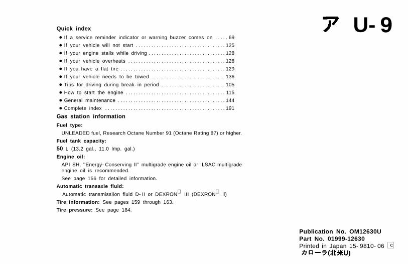
Gas station information
Fuel type:
UNLEADED fuel, Research Octane Number 91 (Octane Rating 87) or higher.
Fuel tank capacity:
50 L (13.2 gal., 11.0 lmp. gal.)
Engine oil:
API SH, ’’Energy- Conserving II’’ multigrade engine oil or ILSAC multigradeengine oil is recommended.
See page 156 for detailed information.
Automatic transaxle fluid:
Automatic transmissiion fluid D- II or DEXRON III (DEXRON ll)
Tire information: See pages 159 through 163.
Tire pressure: See page 184.
U- 9
c
Part 1
1
OPERATION OFINSTRUMENTSAND CONTROLS—
Chapter 1-1Overview of instrumentsand controls
� Instrument panel overview� Instrument cluster overview� Indicator symbols on the
instrument panel
2
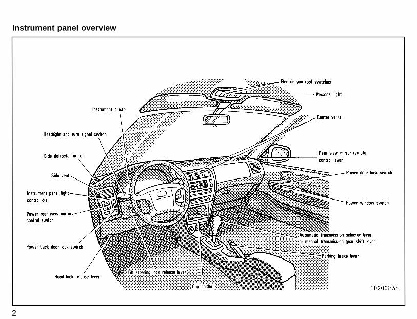
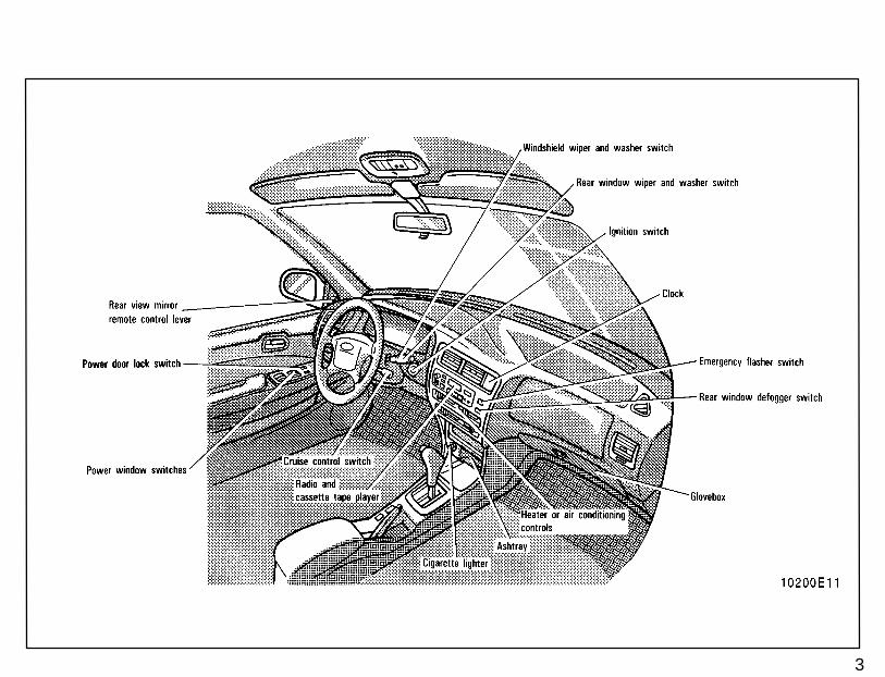
Instrument panel overview
3
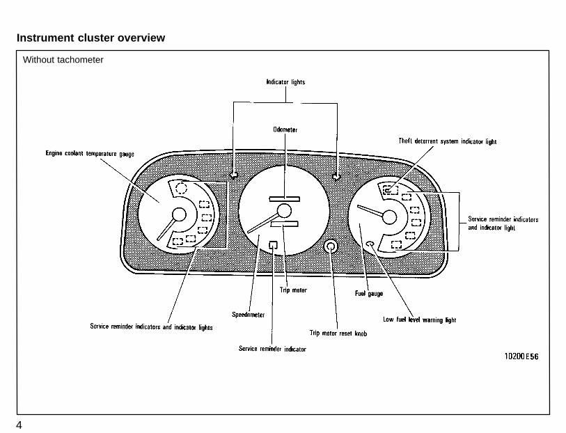
Without tachometer
4
Instrument cluster overview
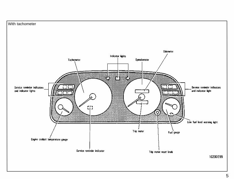
With tachometer
5
6
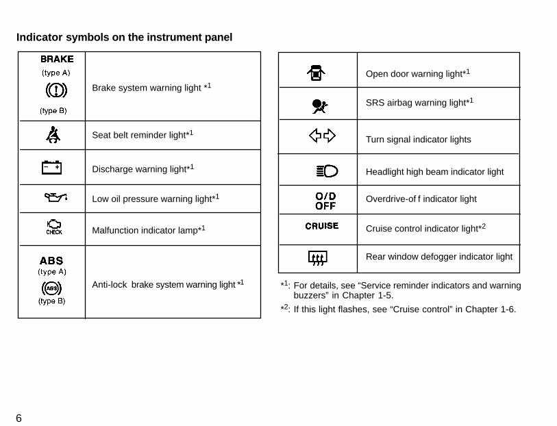
Anti-lock brake system warning light *1
Brake system warning light *1
Seat belt reminder light*1
Discharge warning light*1
Low oil pressure warning light*1
Malfunction indicator lamp*1
Open door warning light*1
SRS airbag warning light*1
Turn signal indicator lights
Headlight high beam indicator light
Overdrive-of f indicator light
Cruise control indicator light*2
Rear window defogger indicator light
*1: For details, see “Service reminder indicators and warningbuzzers” in Chapter 1-5.
*2: If this light flashes, see “Cruise control” in Chapter 1-6.
Indicator symbols on the instrument panel
Part 1 Keys (sedan)
7
OPERATION OFINSTRUMENTSAND CONTROLS—
Chapter 1-2Keys and Doors
� Keys� Side doors� Power windows� Trunk lid� Back door� Hood� Theft deterrent system� Fuel tank cap� Electric sun roof
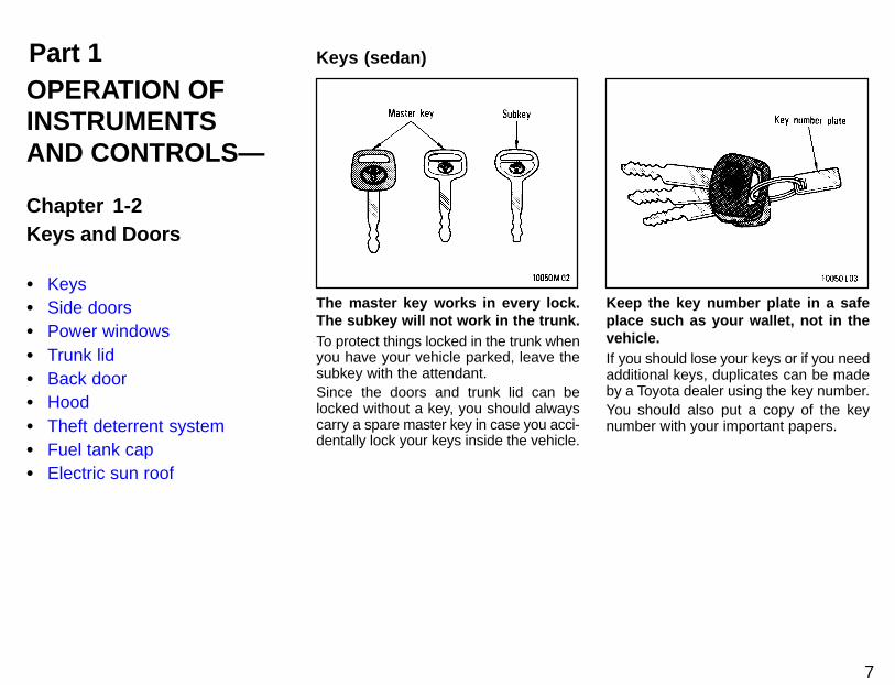
The master key works in every lock.The subkey will not work in the trunk.To protect things locked in the trunk whenyou have your vehicle parked, leave thesubkey with the attendant.Since the doors and trunk lid can belocked without a key, you should alwayscarry a spare master key in case you acci-dentally lock your keys inside the vehicle.
Keep the key number plate in a safeplace such as your wallet, not in thevehicle.If you should lose your keys or if you needadditional keys, duplicates can be madeby a Toyota dealer using the key number.You should also put a copy of the keynumber with your important papers.
8
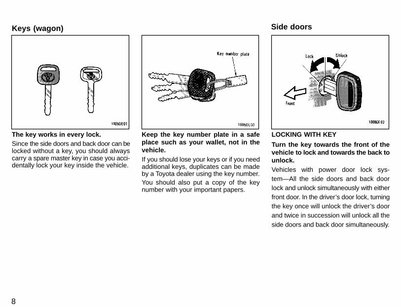
The key works in every lock.Since the side doors and back door can belocked without a key, you should alwayscarry a spare master key in case you acci-dentally lock your key inside the vehicle.
Keep the key number plate in a safeplace such as your wallet, not in thevehicle.If you should lose your keys or if you needadditional keys, duplicates can be madeby a Toyota dealer using the key number.You should also put a copy of the keynumber with your important papers.
LOCKING WITH KEY
Turn the key towards the front of thevehicle to lock and towards the back tounlock.Vehicles with power door lock sys-tem—All the side doors and back doorlock and unlock simultaneously with eitherfront door. In the driver’s door lock, turningthe key once will unlock the driver’s doorand twice in succession will unlock all theside doors and back door simultaneously.
Keys (wagon) Side doors
9
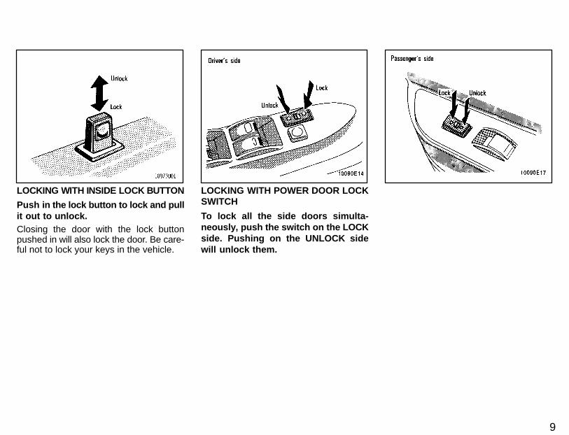
LOCKING WITH INSIDE LOCK BUTTON
Push in the lock button to l ock and pullit out to unlock.Closing the door with the lock buttonpushed in will also lock the door. Be care-ful not to lock your keys in the vehicle.
LOCKING WITH POWER DOOR LOCKSWITCH
To lock all the side doors simulta-neously, push the switch on the LOCKside. Pushing on the UNLOCK sidewill unlock them.
10
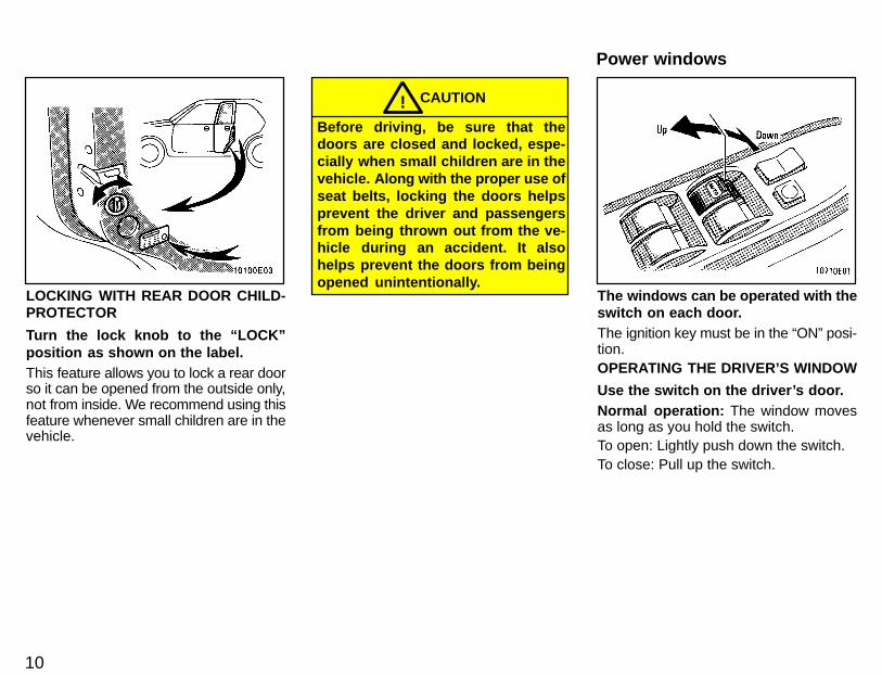
LOCKING WITH REAR DOOR CHILD-PROTECTOR
Turn the lock knob to the “LOCK”position as shown on the label.This feature allows you to lock a rear doorso it can be opened from the outside only,not from inside. We recommend using thisfeature whenever small children are in thevehicle.
CAUTION!Before driving, be sure that thedoors are closed and locked, espe-cially when small children are in thevehicle. A long with the proper use ofseat belts, locking the doors helpsprevent the driver and passengersfrom being thrown out from the ve-hicle during an accident. It alsohelps prevent the doors from beingopened unintentionally.
The windows can be operated with theswitch on each door.The ignition key must be in the “ON” posi-tion.OPERATING THE DRIVER’S WINDOW
Use the switch on the driver’s door.Normal operation: The window movesas long as you hold the switch.To open: Lightly push down the switch.To close: Pull up the switch.
Power windows
11
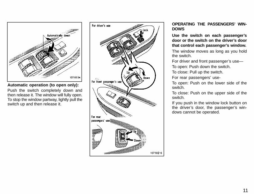
Automatic operation (to open only):Push the switch completely down andthen release it. The window will fully open.To stop the window partway, lightly pull theswitch up and then release it.
OPERATING THE PASSENGERS’ WIN-DOWS
Use the switch on each passenger’sdoor or the switch on the driver’s doorthat control each passenger’s wi ndow.The window moves as long as you holdthe switch.For driver and front passenger’s use—To open: Push down the switch.To close: Pull up the switch.For rear passengers’ use-To open: Push on the lower side of theswitch.To close: Push on the upper side of theswitch.If you push in the window lock button onthe driver’s door, the passenger’s win-dows cannot be operated.

12
CAUTION!To avoid serious personal injury,you must do the following.
� Always make sure the head, handsand other parts of the body of all oc-cupants are kept completely insidethe vehicle before you close thepower windows. If someone’s n eck,head or hands gets caught in a clos-ing window, it could result in a seri-ous injury. When anyone closes thepower windows, be sure that theyoperate the windows safely.
� When small children are in the ve-hicle, never let them use the powerwindow switches without supervi-sion. Use the window lock buttonto prevent them from making unex-pected use of the switches.
� Never leave small children alone inthe vehicle, especially with theignition key still inserted. Theycould use the power windowswitches and get trapped in a win-dow. Unattended children can be-come involved in serious acci-dents.
To open the trunk lid from the outside,insert the master key and turn it clock-wise.See ”Luggage stowage precautions” inPart 2 for precautions to observe in load-ing luggage.To close the trunk lid, lower it and pressdown on it. After closing the trunk lid, trypulling it up to make sure it is securelyclosed.
CAUTION!Keep the trunk lid closed while driv-ing. This not only keeps the luggagefrom being thrown out but also pre-vents exhaust gases from enteringthe vehicle.
To open the trunk lid from the driver’sseat, pull up on the lock release lever.
Trunk lid (sedan)— —Lock release lever
13
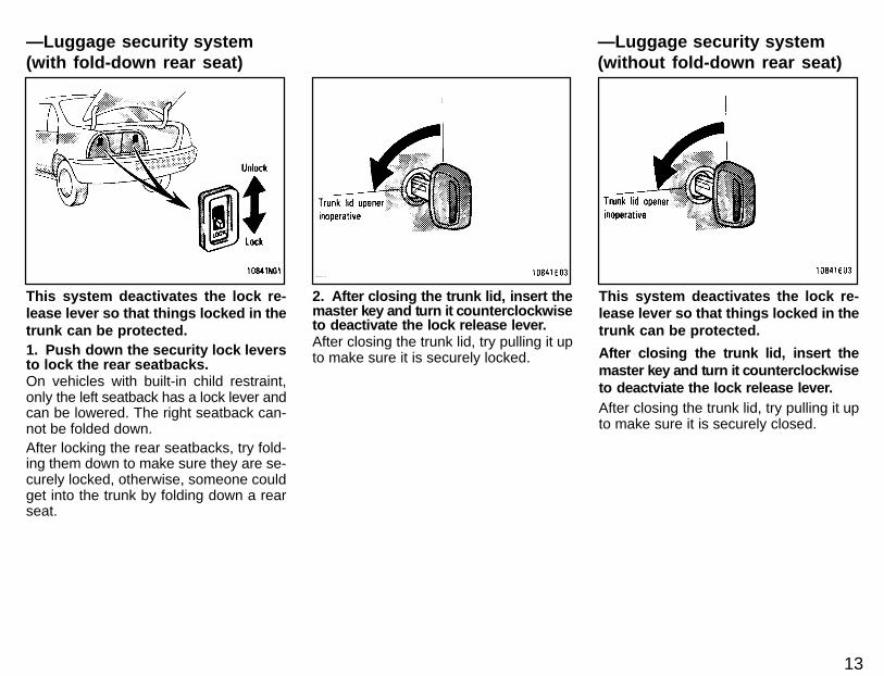
This system deactivates the lock re-lease lever so that things locked in thetrunk can be protected.1. Push down the security lock leversto lock the rear seatbacks.On vehicles with built-in child restraint,only the left seatback has a lock lever andcan be lowered. The right seatback can-not be folded down.After locking the rear seatbacks, try fold-ing them down to make sure they are se-curely locked, otherwise, someone couldget into the trunk by folding down a rearseat.
2. After closing the trunk lid, insert themaster key and turn it counterclockwiseto deactivate the lock release lever.After closing the trunk lid, try pulling it upto make sure it is securely locked.
This system deactivates the lock re-lease lever so that things locked in thetrunk can be protected.
After closing the trunk lid, insert themaster key and turn it counterclockwiseto deactviate the lock release lever.After closing the trunk lid, try pulling it upto make sure it is securely closed.
—Luggage security system(with fold-down rear seat)
—Luggage security system(without fold-down rear seat)
14
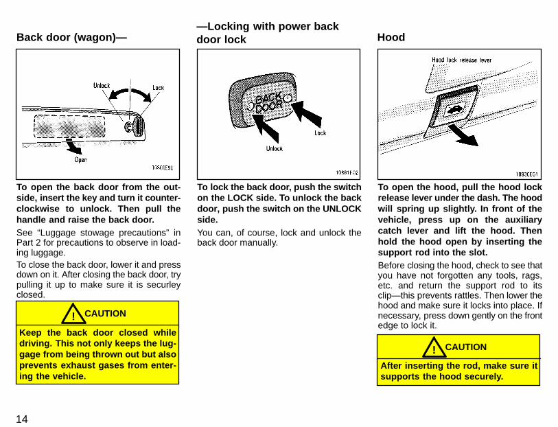
To open the back door from the out-side, insert the key and turn it counter-clockwise to unlock. Then pull thehandle and raise the back door.See “Luggage stowage precautions” inPart 2 for precautions to observe in load-ing luggage.To close the back door, lower it and pressdown on it. After closing the back door, trypulling it up to make sure it is securleyclosed.
Keep the back door closed whiledriving. This not only keeps the lug-gage from being thrown out but alsoprevents exhaust gases from enter-ing the vehicle.
CAUTION!
To lock the back door, push the switchon the LOCK side. To unlock the backdoor, push the switch on the UNLOCKside.You can, of course, lock and unlock theback door manually.
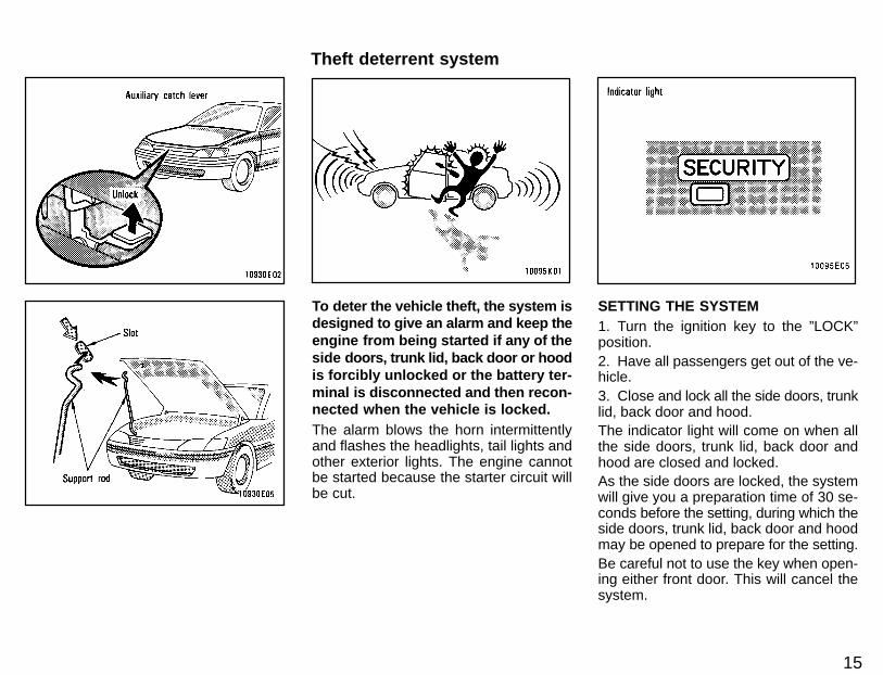
To open the hood, pull the hood lockrelease lever under the dash. The hoodwill spring up slightly. In front of thevehicle, press up on the auxiliarycatch lever and lift the hood. Thenhold the hood open by inserting thesupport rod into the slot.Before closing the hood, check to see thatyou have not forgotten any tools, rags,etc. and return the support rod to itsclip—this prevents rattles. Then lower thehood and make sure it locks into place. Ifnecessary, press down gently on the frontedge to lock it.
After inserting the rod, make sure itsupports the hood securely.
CAUTION!
—Locking with power backdoor lock HoodBack door (wagon)—
15
To deter the vehicle theft, the system isdesigned to give an alarm and keep theengine from being started if any of theside doors, trunk lid, back door or hoodis forcibly unlocked or the battery ter-minal is disconnected and then recon-nected when the vehicle is locked.The alarm blows the horn intermittentlyand flashes the headlights, tail lights andother exterior lights. The engine cannotbe started because the starter circuit willbe cut.
SETTING THE SYSTEM1. Turn the ignition key to the ”LOCK”position.2. Have all passengers get out of the ve-hicle.3. Close and lock all the side doors, trunklid, back door and hood.The indicator light will come on when allthe side doors, trunk lid, back door andhood are closed and locked.As the side doors are locked, the systemwill give you a preparation time of 30 se-conds before the setting, during which theside doors, trunk lid, back door and hoodmay be opened to prepare for the setting.Be careful not to use the key when open-ing either front door. This will cancel thesystem.
Theft deterrent system
16
4. After making sure the indicator lightstarts flashing, you may leave the vehicle.The system will automatically be set afterthe preparation time passes. The indica-tor light will flash to show the system isset. If any of the side doors, trunk lid, backdoor or hood is open at that time, the set-ting is interrupted until it is closed andlocked.Never leave anyone in the vehicle whenyou set the system, because unlockingfrom the inside will activate the system.WHEN THE SYSTEM IS SET
Activating the systemThe system will give the alarm and cut thestarter circuit under the following condi-tions:� If any of the side doors, trunk lid, back
door or hood is unlocked without usingthe key
� If the battery terminal is disconnectedand then reconnected
After 1 minute, the alarm will automatical-ly stop with the starter circuit cut kept on.Reactivating the alarmOnce set, the system automatically resetsthe alarm each time alll the side doors,trunk lid, back door and hood are closedafter the alarm stops.The alarm will be activated again underthe following conditions:
� If any of the side doors, trunk lid, backdoor or hood is opened
� If the battery terminal is disconnectedand then reconnected
Stopping the alarmTurn the igniion key from the ”LOCK” to”ACC” position. The alarm will be stoppedwith the starter circuit cut kept on. Stop-ping the alarm in this manner will keep thealarm from being reactivated when any ofthe side doors, trunk lid, back door or hoodis opened.Interrupting the settingWith the system set, the trunk and backdoor can be opened with the key withoutactivating or cancelling the system. Whileit is open, the side doors and hood may beopened in addition. However, when thebattery terminal is disconnected and thenreconnected, the system is activated.To resume the setting, close and lock theside doors, trunk, back door and hood.The trunk and back door must be closedwith the key removed.CANCELLING THE SYSTEMUnlock either front door with the key. Thiscancels the system completely and thestarter circuit cut will be cancelled at once.INDICATOR LIGHTThe indicator light gives the followingthree indications.
FLASHING—The system is set. Youneed the key to open the side doors, trunklid , back door and hood.ON—The system will automatically be setwhen the time comes. The side doors,trunk lid, back door and hood may beopened without a key.OFF—The system is inactive. You mayopen any of the side doors, trunk lid, backdoor or hood.TESTING THE SYSTEM1. Open all the windows.2. Set the system as described above.The front doors should be locked with thekey. Be sure to wait until the indicator lightstarts flashing.3. Unlock one of the side doors from theinside. The system should activate thealarm.4. Cancel the system by unlocking eitherfront door with the key.5. Repeat this operation for the other sidedoors, trunk lid, back door and hood.When testing on the hood, also check thatthe system is activated when the batteryterminal is disconnected and then recon-nected.If the system does not work properly, haveit checked by your Toyota dealer.

17
1. To open the fuel filler door, pull thelever up.
CAUTION!� Do not smoke, cause sparks or al-
low open flames when refuelling.The fumes are flammable.
� When opening the cap, do not re-move the cap quickly. In hotweather, fuel under pressurecould cause injury by sprayingout of the filler neck if the cap issuddenly removed.
2. To remove the fuel tank cap, turnthe cap slowly counterclockwise, thenpause slightly before removing it. Af-ter removing the cap, hang it on thecap hanger.It is not unusual to hear a slight swooshwhen the cap is opened. When installing,turn the cap clockwise till you hear a click.
CAUTION!� Make sure the cap is tightened se-
curely to prevent fuel spillage incase of an accident.
� Use only a genuine Toyota fueltank cap for replacement. It has abuilt in check valve to reduce fueltank vacuum.
Fuel tank cap Electric sun roof
18
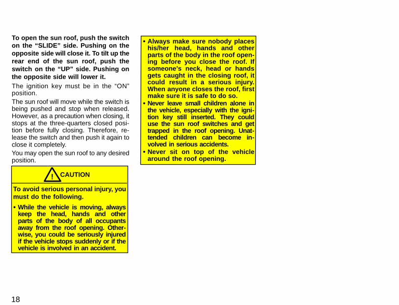
To open the sun roof, push the switchon the “SLIDE” side. Pushing on theopposite side will close it. To tilt up therear end of the sun roof, push theswitch on the “UP” side. Pushing onthe opposite side will lower it.The ignition key must be in the “ON”position.The sun roof will move while the switch isbeing pushed and stop when released.However, as a precaution when closing, itstops at the three-quarters closed posi-tion before fully closing. Therefore, re-lease the switch and then push it again toclose it completely.You may open the sun roof to any desiredposition.
CAUTION!
To avoid serious personal injury, youmust do the following.
� While the vehicle is moving, alwayskeep the head, hands and otherparts of the body of all occupantsaway from the roof opening. Other-wise, you could be seriously injuredif the vehicle stops suddenly or if thevehicle is involved in an accident.
� Always make sure nobody placeshis/her head, hands and otherparts of the body in the roof open-ing before you close the roof. Ifsomeone’s neck, head or handsgets caught in the closing roof, itcould result in a serious injury.When anyone closes the roof, firstmake sure it is safe to do so.
� Never leave small children alone inthe vehicle, especially with the igni-tion key still inserted. They coulduse the sun roof switches and gettrapped in the roof opening. Unat-tended children can become in-volved in serious accidents.
� Never sit on top of the vehiclearound the roof opening.
Part 1 SeatsFront seats——Seat adjustment precautions
19
OPERATION OFINSTRUMENTSAND CONTROLS—
Chapter 1-3Seats, Seat belts,Steering wheeland Mirrors
� Seats� Front seats� Fold-down rear seat� Head restraints� Seat belts� SRS airbags� Child restraint� Tilt steering wheel� Outside rear view mirrors� Anti-glare inside rear view
mirror
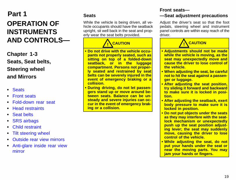
While the vehicle is being driven, all ve-hicle occupants should have the seatbackupright, sit well back in the seat and prop-erly wear the seat belts provided.
CAUTION!� Do not drive with the vehicle occu-
pants not properly seated, such assitting on top of a folded-downseatback, or in the luggagecompartment. Persons not proper-ly seated and restrained by seatbelts can be severely injured in theevent of emergency braking or acollision.
� During driving, do not let passen-gers stand up or move around be-tween seats. Balance can be un-steady and severe injuries can oc-cur in the event of emergency brak-ing or a collision.
Adjust the driver’s seat so that the footpedals, steering wheel and instrumentpanel controls are within easy reach of thedriver.
CAUTION!� Adjustments should not be made
while the vehicle is moving, as theseat may unexpectedly move andcause the driver to lose control ofthe vehicle.
� When adjusting the seat, be carefulnot to hit the seat against a passen-ger or luggage.
� After adjusting the seat position,try sliding it forward and backwardto make sure it is locked in posi-tion.
� After adjusting the seatback, exertbody pressure to make sure it islocked in position.
� Do not put objects under the seatsas they may interfere with the seat-lock mechanism or unexpectedlypush up the seat position adjust-ing lever; the seat may suddenlymove, causing the driver to losecontrol of the vehicle.
� While adjusting the seat, do notput your hands under the seat ornear the moving parts. You mayjam your hands or fingers.
20
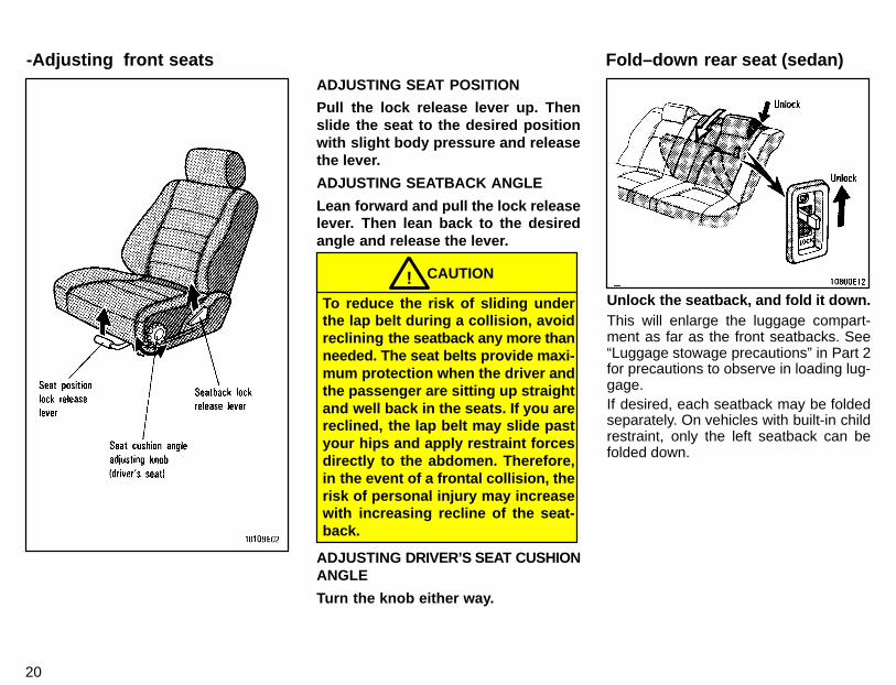
ADJUSTING SEAT POSITION
Pull the lock release lever up. Thenslide the seat to the desired positionwith slight body pressure and releasethe lever.
ADJUSTING SEATBACK ANGLE
Lean forward and pull the lock releaselever. Then lean back to the desiredangle and release the lever.
CAUTION!To reduce the risk of sliding underthe lap belt during a collision, avoidreclining the seatback any more thanneeded. The seat belts provide maxi-mum protection when the driver andthe passenger are sitting up straightand well back in the seats. If you arereclined, the lap belt may slide pastyour hips and apply restraint forcesdirectly to the abdomen. Therefore,in the event of a frontal collision, therisk of personal injury may increasewith increasing recline of the seat-back.
ADJUSTING DRIVER’S SEAT CUSHIONANGLE
Turn the knob either way.
Unlock the seatback, and fold it down.This will enlarge the luggage compart-ment as far as the front seatbacks. See“Luggage stowage precautions” in Part 2for precautions to observe in loading lug-gage.If desired, each seatback may be foldedseparately. On vehicles with built-in childrestraint, only the left seatback can befolded down.
Fold–down rear seat (sedan)-Adjusting front seats
21
CAUTION!When returning the seatback to theupright position:
� Make sure the seat belts are nottwisted or caught in the seatbackand are arranged in their properposition for ready use.
� Make sure the seatback is securelylocked by pushing forward andrearward on the top of the seat-back.
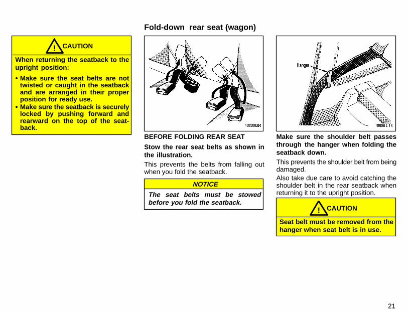
BEFORE FOLDING REAR SEAT
Stow the rear seat belts as shown inthe illustration.This prevents the belts from falling outwhen you fold the seatback.
NOTICE
The seat belts must be stowedbefore you fold the seatback.
Make sure the shoulder belt passesthrough the hanger when folding theseatback down.This prevents the shoulder belt from beingdamaged.Also take due care to avoid catching theshoulder belt in the rear seatback whenreturning it to the upright position.
CAUTION!Seat belt must be removed from thehanger when seat belt is in use.
Fold-down rear seat (wagon)
22
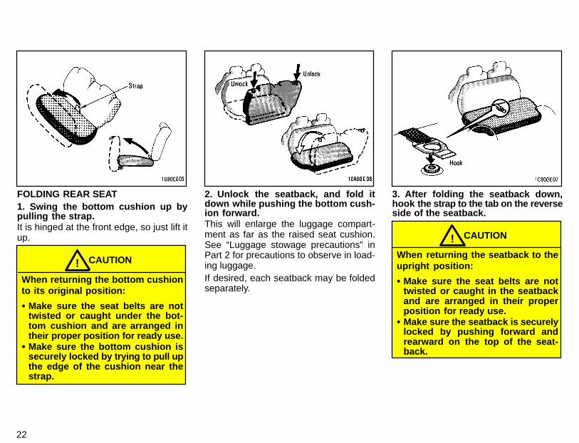
FOLDING REAR SEAT1. Swing the bottom cushion up bypulling the strap.It is hinged at the front edge, so just lift itup.
CAUTION!When returning the bottom cushionto its original position:
� Make sure the seat belts are nottwisted or caught under the bot-tom cushion and are arranged intheir proper position for ready use.
� Make sure the bottom cushion issecurely locked by trying to pull upthe edge of the cushion near thestrap.
2. Unlock the seatback, and fold itdown while pushing the bottom cush-ion forward.This will enlarge the luggage compart-ment as far as the raised seat cushion.See “Luggage stowage precautions” inPart 2 for precautions to observe in load-ing luggage.If desired, each seatback may be foldedseparately.
3. After folding the seatback down,hook the strap to the tab on the reverseside of the seatback.
CAUTION!When returning the seatback to theupright position:
� Make sure the seat belts are nottwisted or caught in the seatbackand are arranged in their properposition for ready use.
� Make sure the seatback is securelylocked by pushing forward andrearward on the top of the seat-back.

23
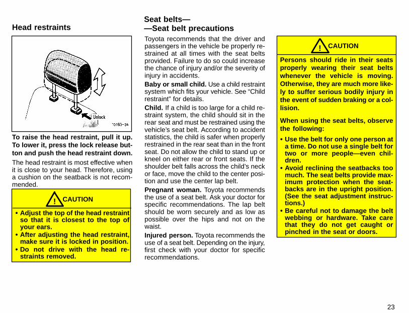
To raise the head restraint, pull it up.To lower it, press the lock release but-ton and push the head restraint down.The head restraint is most effective whenit is close to your head. Therefore, usinga cushion on the seatback is not recom-mended.
CAUTION!� Adjust the top of the head restraint
so that it is closest to the top ofyour ears.
� After adjusting the head restraint,make sure it is locked in position.
� Do not drive with the head re-straints removed.
Toyota recommends that the driver andpassengers in the vehicle be properly re-strained at all times with the seat beltsprovided. Failure to do so could increasethe chance of injury and/or the severity ofinjury in accidents.Baby or small child. Use a child restraintsystem which fits your vehicle. See “Childrestraint” for details.Child. If a child is too large for a child re-straint system, the child should sit in therear seat and must be restrained using thevehicle’s seat belt. According to accidentstatistics, the child is safer when properlyrestrained in the rear seat than in the frontseat. Do not allow the child to stand up orkneel on either rear or front seats. If theshoulder belt falls across the child’s neckor face, move the child to the center posi-tion and use the center lap belt.Pregnant woman. Toyota recommendsthe use of a seat belt. Ask your doctor forspecific recommendations. The lap beltshould be worn securely and as low aspossible over the hips and not on thewaist.Injured person. Toyota recommends theuse of a seat belt. Depending on the injury,first check with your doctor for specificrecommendations.
CAUTION!Persons should ride in their seatsproperly wearing their seat beltswhenever the vehicle is moving.Otherwise, they are much more like-ly to suffer serious bodily injury inthe event of sudden braking or a col-lision.
When using the seat belts, observethe following:
� Use the belt for only one person ata time. Do not use a single belt fortwo or more people—even chil-dren.
� Avoid reclining the seatbacks toomuch. The seat belts provide max-imum protection when the seat-backs are in the upright position.(See the seat adjustment instruc-tions.)
� Be careful not to damage the beltwebbing or hardware. Take carethat they do not get caught orpinched in the seat or doors.
Seat belts——Seat belt precautionsHead restraints
23
To raise the head restraint, pull it up.To lower it, press the lock release but-ton and push the head restraint down.The head restraint is most effective whenit is close to your head. Therefore, usinga cushion on the seatback is not recom-mended.
CAUTION!� Adjust the top of the head restraint
so that it is closest to the top ofyour ears.
� After adjusting the head restraint,make sure it is locked in position.
� Do not drive with the head re-straints removed.
Toyota recommends that the driver andpassengers in the vehicle be properly re-strained at all times with the seat beltsprovided. Failure to do so could increasethe chance of injury and/or the severity ofinjury in accidents.Baby or small child. Use a child restraintsystem which fits your vehicle. See “Childrestraint” for details.Child. If a child is too large for a child re-straint system, the child should sit in therear seat and must be restrained using thevehicle’s seat belt. According to accidentstatistics, the child is safer when properlyrestrained in the rear seat than in the frontseat. Do not allow the child to stand up orkneel on either rear or front seats. If theshoulder belt falls across the child’s neckor face, move the child to the center posi-tion and use the center lap belt.Pregnant woman. Toyota recommendsthe use of a seat belt. Ask your doctor forspecific recommendations. The lap beltshould be worn securely and as low aspossible over the hips and not on thewaist.Injured person. Toyota recommends theuse of a seat belt. Depending on the injury,first check with your doctor for specificrecommendations.
CAUTION!Persons should ride in their seatsproperly wearing their seat beltswhenever the vehicle is moving.Otherwise, they are much more like-ly to suffer serious bodily injury inthe event of sudden braking or a col-lision.
When using the seat belts, observethe following:
� Use the belt for only one person ata time. Do not use a single belt fortwo or more people—even chil-dren.
� Avoid reclining the seatbacks toomuch. The seat belts provide max-imum protection when the seat-backs are in the upright position.(See the seat adjustment instruc-tions.)
� Be careful not to damage the beltwebbing or hardware. Take carethat they do not get caught orpinched in the seat or doors.
Seat belts——Seat belt precautionsHead restraints
24
� Inspect the belt system periodical-ly. Check for cuts, fraying, andloose parts. Damaged parts shouldbe replaced. Do not disassemble ormodify the system.
� Keep the belts clean and dry. If theyneed cleaning, use a mild soapsolution or lukewarm water. Neveruse bleach, dye, or abrasive clean-ers—they may severely weaken thebelts.
� Replace the belt assembly (includ-ing bolts) if it has been used in a se-vere impact. The entire assemblyshould be replaced even if damageis not obvious.
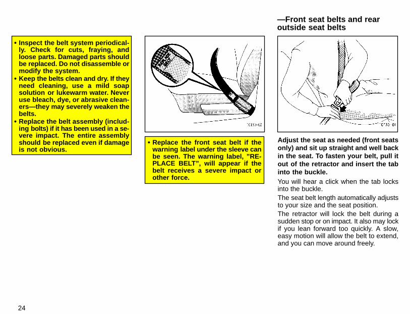
� Replace the front seat belt if thewarning label under the sleeve canbe seen. The warning label, ”RE-PLACE BELT”, will appear if thebelt receives a severe impact orother force.
Adjust the seat as needed (front seatsonly) and sit up straight and well backin the seat. To fasten your belt, pull itout of the retractor and insert the tabinto the buckle.You will hear a click when the tab locksinto the buckle.The seat belt length automatically adjuststo your size and the seat position.The retractor will lock the belt during asudden stop or on impact. It also may lockif you lean forward too quickly. A slow,easy motion will allow the belt to extend,and you can move around freely.
—Front seat belts and rearoutside seat belts
25
If the seat belt cannot be pulled out of theretractor, firmly pull the belt and release it.You will then be able to smoothly pull thebelt out of the retractor.When a passenger’s shoulder belt is com-pletely extended and is then retractedeven slightly, the belt is locked in that posi-tion and cannot be extended. This featureis used to hold the child restraint systemsecurely. (For details, see “Child restraint”in this chapter.) To free the belt again, fullyretract the belt and then pull the belt outonce more.
CAUTION!
� After inserting the tab, make surethe tab and buckle are locked andthat the belt is not twisted.
� Do not insert coins, clips, etc. inthe buckle as this may prevent youfrom properly latching the tab andbuckle.
� If the seat belt does not functionnormally, immediately contact yourToyota dealer.
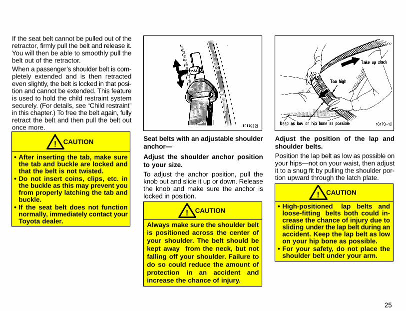
Seat belts with an adjustable shoulderanchor—
Adjust the shoulder anchor positionto your size.To adjust the anchor position, pull theknob out and slide it up or down. Releasethe knob and make sure the anchor islocked in position.
CAUTION!Always make sure the shoulder beltis positioned across the center ofyour shoulder. The belt should bekept away from the neck, but notfalling off your shoulder. Failure todo so could reduce the amount ofprotection in an accident andincrease the chance of injury.
Adjust the position of the lap andshoulder belts.Position the lap belt as low as possible onyour hips—not on your waist, then adjustit to a snug fit by pulling the shoulder por-tion upward through the latch plate.
CAUTION!� High-positioned lap belts and
loose-fitting belts both could in-crease the chance of injury due tosliding under the lap belt during anaccident. Keep the lap belt as lowon your hip bone as possible.
� For your safety, do not place theshoulder belt under your arm.
26
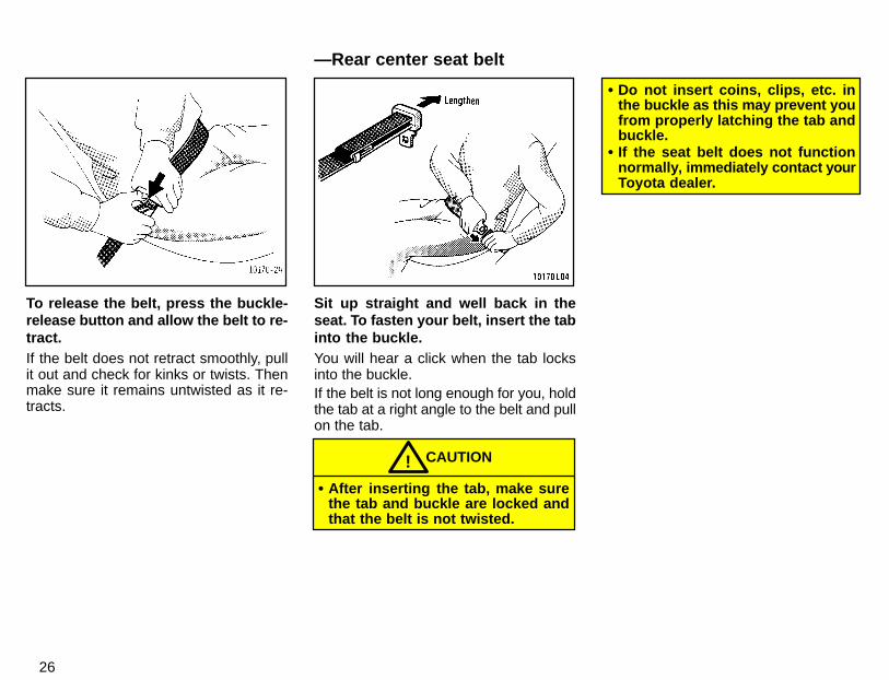
To release the belt, press the buckle-release button and allow the belt to re-tract.If the belt does not retract smoothly, pullit out and check for kinks or twists. Thenmake sure it remains untwisted as it re-tracts.
Sit up straight and well back in theseat. To fasten your belt, insert the tabinto the buckle.You will hear a click when the tab locksinto the buckle.If the belt is not long enough for you, holdthe tab at a right angle to the belt and pullon the tab.
CAUTION!� After inserting the tab, make sure
the tab and buckle are locked andthat the belt is not twisted.
� Do not insert coins, clips, etc. inthe buckle as this may prevent youfrom properly latching the tab andbuckle.
� If the seat belt does not functionnormally, immediately contact yourToyota dealer.
—Rear center seat belt
27
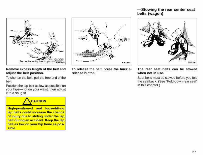
Remove excess length of the belt andadjust the belt position.To shorten the belt, pull the free end of thebelt.Position the lap belt as low as possible onyour hips—not on your waist, then adjustit to a snug fit.
CAUTION!High-positioned and loose-fittinglap belts could increase the chanceof injury due to sliding under the lapbelt during an accident. Keep the lapbelt as low on your hip bone as pos-sible.
To release the belt, press the buckle-release button.
The rear seat belts can be stowedwhen not in use.Seat belts must be stowed before you foldthe seatback. (See “Fold-down rear seat”in this chapter.)
—Stowing the rear center seatbelts (wagon)
28
If your seat belt cannot be fastened se-curely because it is not long enough, apersonalized seat belt extender is avail-able from your Toyota dealer free ofcharge.Please contact your local Toyota dealerso that the dealer can order the proper re-quired length for the extender. Bring theheaviest coat you expect to wear for prop-er measurement and selection of length.Additional ordering information is avail-able at your Toyota dealer.
CAUTION!When using the seat belt extender,observe the following. Failure tofollow these instructions could re-sult in less effectiveness of the seatbelt restraint system in case of ve-hicle accident, increasing thechance of personal injury.
� Never use the seat belt extender ifyou can fasten the seat belt with-out it.
� Remember that the extender pro-vided for you may not be safewhen used on a different vehicle,or for another person or at a differ-ent seating position than the oneoriginally intended for.
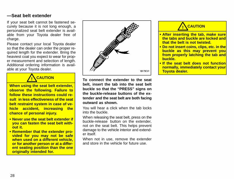
To connect the extender to the seatbelt, insert the tab into the seat beltbuckle so that the “PRESS” signs onthe buckle-release buttons of the ex-tender and the seat belt are both facingoutward as shown.You will hear a click when the tab locksinto the buckle.When releasing the seat belt, press on thebuckle-release button on the extender,not on the seat belt. This helps preventdamage to the vehicle interior and extend-er itself.When not in use, remove the extenderand store in the vehicle for future use.
CAUTION!� After inserting the tab, make sure
the tabs and buckle are locked andthat the belt is not twisted.
� Do not insert coins, clips, etc. in thebuckle as this may prevent youfrom properly latching the tab andbuckle.
� If the seat belt does not functionnormally, immediately contact yourToyota dealer.
—Seat belt extender
29
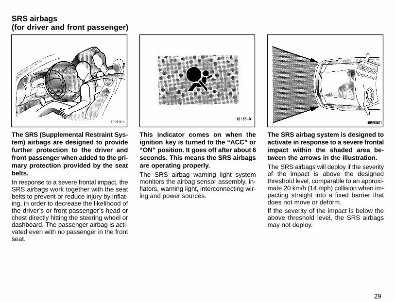
The SRS (Supplemental Restraint Sys-tem) airbags are designed to providefurther protection to the driver andfront passenger when added to the pri-mary protection provided by the seatbelts.In response to a severe frontal impact, theSRS airbags work together with the seatbelts to prevent or reduce injury by inflat-ing, in order to decrease the likelihood ofthe driver’s or front passenger’s head orchest directly hitting the steering wheel ordashboard. The passenger airbag is acti-vated even with no passenger in the frontseat.
This indicator comes on when theignition key is turned to the “ACC” or“ON” position. It goes off after about 6seconds. This means the SRS airbagsare operating properly.The SRS airbag warning light systemmonitors the airbag sensor assembly, in-flators, warning light, interconnecting wir-ing and power sources.
The SRS airbag system is designed toactivate in response to a severe frontalimpact within the shaded area be-tween the arrows in the illustration.The SRS airbags will deploy if the severityof the impact is above the designedthreshold level, comparable to an approxi-mate 20 km/h (14 mph) collision when im-pacting straight into a fixed barrier thatdoes not move or deform.If the severity of the impact is below theabove threshold level, the SRS airbagsmay not deploy.
SRS airbags(for driver and front passenger)
30
However, this threshold velocity will beconsiderably higher if the vehicle strikesan object, such as a parked vehicle or signpole, which can move or deform on im-pact, or if it is involved in an underride col-lision (a collision in which the nose of thevehicle “underrides”, or goes under, thebed of a truck).It is possible with collision severity at themarginal level of airbag sensor detectionand activation that only one of your ve-hicle’s two airbags will deploy.For your safety, be sure to always wearyour seat belts. The SRS airbags are not designed to
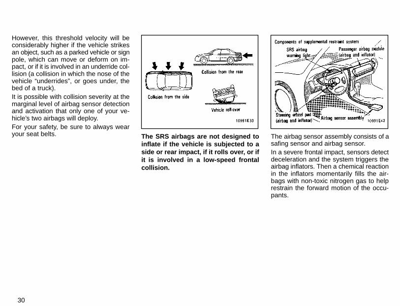
inflate if the vehicle is subjected to aside or rear impact, if it rolls over, or ifit is involved in a low-speed frontalcollision.
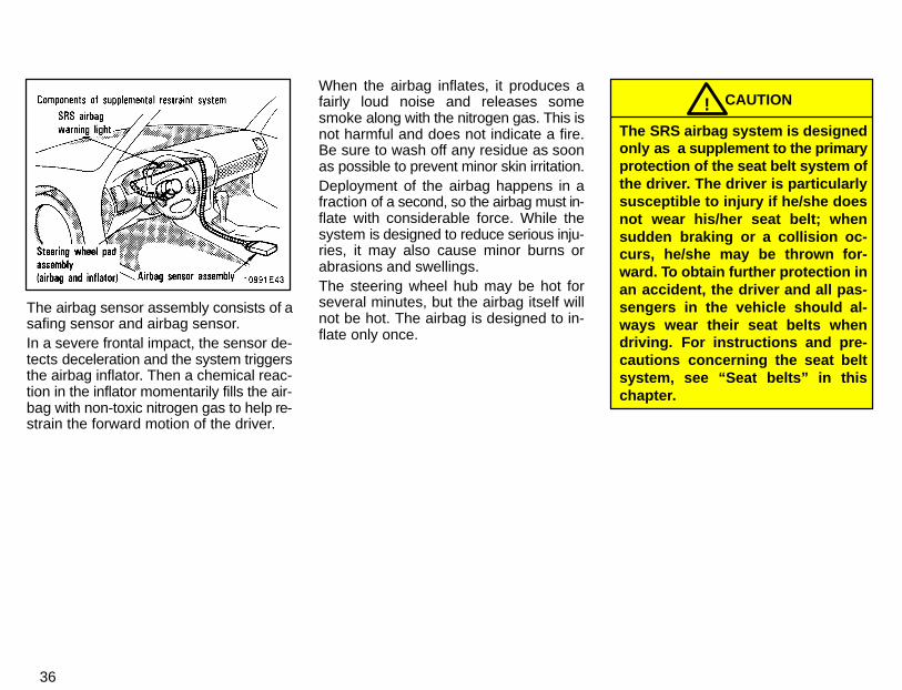
The airbag sensor assembly consists of asafing sensor and airbag sensor.In a severe frontal impact, sensors detectdeceleration and the system triggers theairbag inflators. Then a chemical reactionin the inflators momentarily fills the air-bags with non-toxic nitrogen gas to helprestrain the forward motion of the occu-pants.
31
When the airbags inflate, they produce afairly loud noise and release some smokealong with the nitrogen gas. This is notharmful and does not indicate a fire. Besure to wash off any residue as soon aspossible to prevent minor skin irritation.Deployment of the airbags happen in afraction of a second, so the airbags mustinflate with considerable force. While thesystem is designed to reduce serious inju-ries, it may also cause minor burns orabrasions and swellings.Parts of the airbag module (steeringwheel hub, dashboard) may be hot forseveral minutes, but the airbags them-selves will not be hot. The airbags are de-signed to inflate only once.A crash severe enough to inflate the air-bags may break the windshield as the ve-hicle buckles. In vehicles with a passen-ger airbag the windshield may also bedamaged by absorbing some of the forceof the inflating airbag.
CAUTION!� The SRS airbag system is de-
signed only as a supplement tothe primary protection of the seatbelt systems of the driver andfront passenger. The front seat oc-cupants are particularly suscepti-ble to injury if they do not weartheir seat belts; when suddenbraking or a collision occurs, theymay be thrown forward. To obtainfurther protection in an accident,the driver and all passengers inthe vehicle should always weartheir seat belts when driving. Forinstructions and precautions con-cerning the seat belt system, see“Seat belts” in this chapter.
� A baby or small child who is toosmall to use a seat belt should beproperly secured in a rear seat us-ing a child restraint system.
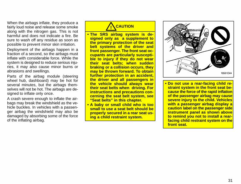
� Do not use a rear-facing child re-straint system in the front seat be-cause the force of the rapid inflationof the passenger airbag may causesevere injury to the child. Vehicleswith a passenger airbag display acaution label on the passenger sideinstrument panel as shown aboveto remind you not to install a rear-facing child restraint system on thefront seat.

32
� When using a forward-facing childrestraint system in the front seat,the seat must be moved as far backas possible. For instructions con-cerning the installation of a childrestraint system, see “Child re-straint” in this chapter.
� Do not sit on the edge of the seat orlean over the dashboard when thevehicle is in use. The airbags inflatewith considerable speed and force;you may be severely injured. Sit upstraight and well back in the seat,and always use your seat belt.
� Do not allow a child to stand up, orto kneel on the front passengerseat. The airbag inflates with con-siderable speed and force; thechild may be severely injured.
� Do not hold a child on your lap or inyour arms. Use a child restraintsystem in the rear seat. For instruc-tions concerning the installation ofa child restraint system, see “Childrestraint” in this chapter.
33
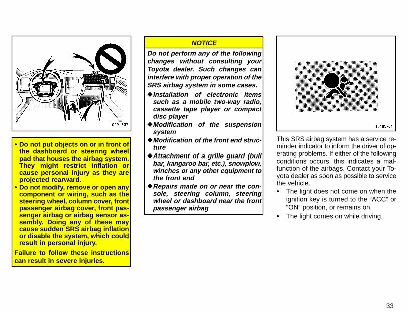
� Do not put objects on or in front ofthe dashboard or steering wheelpad that houses the airbag system.They might restrict inflation orcause personal injury as they areprojected rearward.
� Do not modify, remove or open anycomponent or wiring, such as thesteering wheel, column cover, frontpassenger airbag cover, front pas-senger airbag or airbag sensor as-sembly. Doing any of these maycause sudden SRS airbag inflationor disable the system, which couldresult in personal injury.
Failure to follow these instructionscan result in severe injuries.
Do not perform any of the followingchanges without consulting yourToyota dealer. Such changes caninterfere with proper operation of theSRS airbag system in some cases.�Installation of electronic items
such as a mobile two-way radio,cassette tape player or compactdisc player
�Modification of the suspensionsystem
�Modification of the front end struc-ture
�Attachment of a grille guard (bullbar, kangaroo bar, etc.), snowplow,winches or any other equipment tothe front end
�Repairs made on or near the con-sole, steering column, steeringwheel or dashboard near the frontpassenger airbag
NOTICE
This SRS airbag system has a service re-minder indicator to inform the driver of op-erating problems. If either of the followingconditions occurs, this indicates a mal-function of the airbags. Contact your To-yota dealer as soon as possible to servicethe vehicle.� The light does not come on when the
ignition key is turned to the “ACC” or“ON” position, or remains on.
� The light comes on while driving.
34
In the following cases, contact yourToyota dealer as soon as possible:� The SRS airbags have been inflated.� The front part of the vehicle (shaded in
the illustration) was involved in an ac-cident not of the extent to cause theSRS airbags to inflate
� The pad section of the steering wheelor front passenger airbag cover(shaded in the illustration) is scratched,cracked, or otherwise damaged.
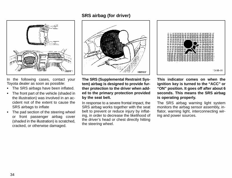
The SRS (Supplemental Restraint Sys-tem) airbag is designed to provide fur-ther protection to the driver when add-ed to the primary protection providedby the seat belt.In response to a severe frontal impact, theSRS airbag works together with the seatbelt to prevent or reduce injury by inflat-ing, in order to decrease the likelihood ofthe driver’s head or chest directly hittingthe steering wheel.
This indicator comes on when theignition key is turned to the “ACC” or“ON” position. It goes off after about 6seconds. This means the SRS airbagis operating properly.The SRS airbag warning light systemmonitors the airbag sensor assembly, in-flator, warning light, interconnecting wir-ing and power sources.
SRS airbag (for driver)
35
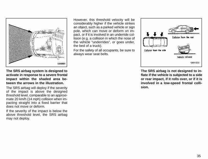
The SRS airbag system is designed toactivate in response to a severe frontalimpact within the shaded area be-tween the arrows in the illustration.The SRS airbag will deploy if the severityof the impact is above the designedthreshold level, comparable to an approxi-mate 20 km/h (14 mph) collision when im-pacting straight into a fixed barrier thatdoes not move or deform.If the severity of the impact is below theabove threshold level, the SRS airbagmay not deploy.
However, this threshold velocity will beconsiderably higher if the vehicle strikesan object, such as a parked vehicle or signpole, which can move or deform on im-pact, or if it is involved in an underride col-lision (e.g. a collision in which the nose ofthe vehicle “underrides”, or goes under,the bed of a truck).For the safety of all occupants, be sure toalways wear seat belts.
The SRS airbag is not designed to in-flate if the vehicle is subjected to a sideor rear impact, if it rolls over, or if it isinvolved in a low-speed frontal colli-sion.
36
The airbag sensor assembly consists of asafing sensor and airbag sensor.In a severe frontal impact, the sensor de-tects deceleration and the system triggersthe airbag inflator. Then a chemical reac-tion in the inflator momentarily fills the air-bag with non-toxic nitrogen gas to help re-strain the forward motion of the driver.
When the airbag inflates, it produces afairly loud noise and releases somesmoke along with the nitrogen gas. This isnot harmful and does not indicate a fire.Be sure to wash off any residue as soonas possible to prevent minor skin irritation.Deployment of the airbag happens in afraction of a second, so the airbag must in-flate with considerable force. While thesystem is designed to reduce serious inju-ries, it may also cause minor burns orabrasions and swellings.The steering wheel hub may be hot forseveral minutes, but the airbag itself willnot be hot. The airbag is designed to in-flate only once.
CAUTION!The SRS airbag system is designedonly as a supplement to the primaryprotection of the seat belt system ofthe driver. The driver is particularlysusceptible to injury if he/she doesnot wear his/her seat belt; whensudden braking or a collision oc-curs, he/she may be thrown for-ward. To obtain further protection inan accident, the driver and all pas-sengers in the vehicle should al-ways wear their seat belts whendriving. For instructions and pre-cautions concerning the seat beltsystem, see “Seat belts” in thischapter.
37
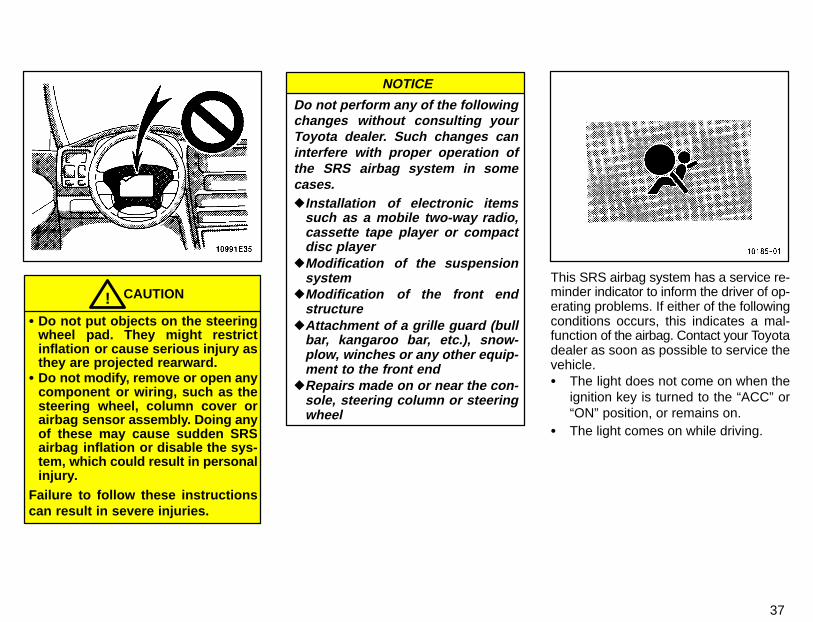
CAUTION!� Do not put objects on the steering
wheel pad. They might restrictinflation or cause serious injury asthey are projected rearward.
� Do not modify, remove or open anycomponent or wiring, such as thesteering wheel, column cover orairbag sensor assembly. Doing anyof these may cause sudden SRSairbag inflation or disable the sys-tem, which could result in personalinjury.
Failure to follow these instructionscan result in severe injuries.
Do not perform any of the followingchanges without consulting yourToyota dealer. Such changes caninterfere with proper operation ofthe SRS airbag system in somecases.�Installation of electronic items
such as a mobile two-way radio,cassette tape player or compactdisc player
�Modification of the suspensionsystem
�Modification of the front endstructure
�Attachment of a grille guard (bullbar, kangaroo bar, etc.), snow-plow, winches or any other equip-ment to the front end
�Repairs made on or near the con-sole, steering column or steeringwheel
NOTICE
This SRS airbag system has a service re-minder indicator to inform the driver of op-erating problems. If either of the followingconditions occurs, this indicates a mal-function of the airbag. Contact your Toyotadealer as soon as possible to service thevehicle.� The light does not come on when the
ignition key is turned to the “ACC” or“ON” position, or remains on.
� The light comes on while driving.

38
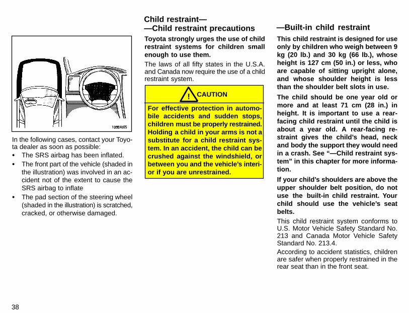
In the following cases, contact your Toyo-ta dealer as soon as possible:� The SRS airbag has been inflated.� The front part of the vehicle (shaded in
the illustration) was involved in an ac-cident not of the extent to cause theSRS airbag to inflate
� The pad section of the steering wheel(shaded in the illustration) is scratched,cracked, or otherwise damaged.
Toyota strongly urges the use of childrestraint systems for children smallenough to use them.The laws of all fifty states in the U.S.A.and Canada now require the use of a childrestraint system.
CAUTION!For effective protection in automo-bile accidents and sudden stops,children must be properly restrained.Holding a child in your arms is not asubstitute for a child restraint sys-tem. In an accident, the child can becrushed against the windshield, orbetween you and the vehicle’s interi-or if you are unrestrained.
This child restraint is designed for useonly by children who weigh between 9kg (20 lb.) and 30 kg (66 lb.), whoseheight is 127 cm (50 in.) or less, whoare capable of sitting upright alone,and whose shoulder height is lessthan the shoulder belt slots in use.
The child should be one year old ormore and at least 71 cm (28 in.) inheight. It is important to use a rear-facing child restraint until the child isabout a year old. A rear-facing re-straint gives the child’s head, neckand body the support they would needin a crash. See “—Child restraint sys-tem” in this chapter for more informa-tion.
If your child’s shoulders are above theupper shoulder belt position, do notuse the built-in child restraint. Yourchild should use the vehicle’s seatbelts.This child restraint system conforms toU.S. Motor Vehicle Safety Standard No.213 and Canada Motor Vehicle SafetyStandard No. 213.4.According to accident statistics, childrenare safer when properly restrained in therear seat than in the front seat.
Child restraint——Child restraint precautions —Built-in child restraint
38
In the following cases, contact your Toyo-ta dealer as soon as possible:� The SRS airbag has been inflated.� The front part of the vehicle (shaded in
the illustration) was involved in an ac-cident not of the extent to cause theSRS airbag to inflate
� The pad section of the steering wheel(shaded in the illustration) is scratched,cracked, or otherwise damaged.
Toyota strongly urges the use of childrestraint systems for children smallenough to use them.The laws of all fifty states in the U.S.A.and Canada now require the use of a childrestraint system.
CAUTION!For effective protection in automo-bile accidents and sudden stops,children must be properly restrained.Holding a child in your arms is not asubstitute for a child restraint sys-tem. In an accident, the child can becrushed against the windshield, orbetween you and the vehicle’s interi-or if you are unrestrained.
This child restraint is designed for useonly by children who weigh between 9kg (20 lb.) and 30 kg (66 lb.), whoseheight is 127 cm (50 in.) or less, whoare capable of sitting upright alone,and whose shoulder height is lessthan the shoulder belt slots in use.
The child should be one year old ormore and at least 71 cm (28 in.) inheight. It is important to use a rear-facing child restraint until the child isabout a year old. A rear-facing re-straint gives the child’s head, neckand body the support they would needin a crash. See “—Child restraint sys-tem” in this chapter for more informa-tion.
If your child’s shoulders are above theupper shoulder belt position, do notuse the built-in child restraint. Yourchild should use the vehicle’s seatbelts.This child restraint system conforms toU.S. Motor Vehicle Safety Standard No.213 and Canada Motor Vehicle SafetyStandard No. 213.4.According to accident statistics, childrenare safer when properly restrained in therear seat than in the front seat.
Child restraint——Child restraint precautions —Built-in child restraint
39
CAUTION!Make sure the child is securely re-strained with the built-in child re-straint. Failure to follow the manufac-turer’s instructions on the use of thischild restraint system can result inyour child striking the vehicle’s inte-rior during a sudden stop or crash.Snugly adjust the belts provided withthe child restraint around your child.
When using the built-in child re-straint, observe the following:
� Use the belts for only one child ata time. Do not use the belts for twoor more children.
� Be careful not to damage the beltwebbing or hardware. Take carethat they do not get caught orpinched in the seatback.
� Inspect the belt system periodical-ly. Check for cuts, fraying, andloose parts. Damaged parts shouldbe replaced. Do not disassemble ormodify the child restraint belt sys-tem.
� Keep the belts clean and dry. If theyneed cleaning, use a mild soapsolution or lukewarm water. Neveruse bleach, dye, or abrasive clean-ers—they may severely weaken thebelts.
� Replace the built-in child restraintassembly if it has been used in asevere impact. The entire assem-bly should be replaced even ifdamage is not obvious.
� Do not use another child restraintsystem over the opened built-inchild restraint.
� Do not use the adult lap and shoul-der belt with the built-in child re-straint.
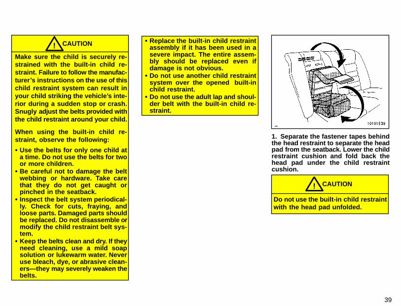
1. Separate the fastener tapes behindthe head restraint to separate the headpad from the seatback. Lower the childrestraint cushion and fold back thehead pad under the child restraintcushion.
CAUTION!
Do not use the built-in child restraintwith the head pad unfolded.

40
2. While pulling the seat belt releasestrap in the child seat cushion, pullboth shoulder belts together.Pull the seat belt release strap from aboveat about 45� angle to the child seat cush-ion.If the shoulder belts cannot be pulled out,return the child seat cushion to an almostclosed position, firmly pull the seat belt re-lease strap and at the same time pull bothshoulder belts, then lower the child seatcushion again.
3. Compress the shoulder belt clip toseparate the right and left shoulderbelts.
4. Add slack to the shoulder belts bypulling both of them together whilepulling the black seat belt releasestrap (see step 4 for illustrated instruc-tion). Then pull down the seatbackpart of the removable pad. Determinethe proper shoulder belt slot height foryour child. Select the slots at or justabove the top of the child’s shoulders.The child seat pad is attached by fastenertapes.
CAUTION!If you remove the child seat pad forcleaning etc., do not use the built-inchild restraint without the pad.
41
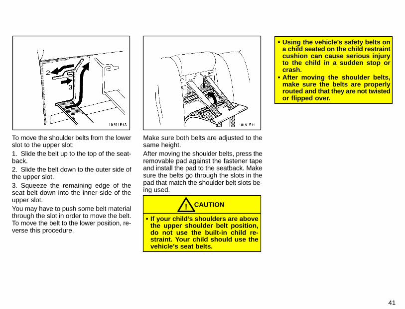
To move the shoulder belts from the lowerslot to the upper slot:1. Slide the belt up to the top of the seat-back.2. Slide the belt down to the outer side ofthe upper slot.3. Squeeze the remaining edge of theseat belt down into the inner side of theupper slot.You may have to push some belt materialthrough the slot in order to move the belt.To move the belt to the lower position, re-verse this procedure.
Make sure both belts are adjusted to thesame height.After moving the shoulder belts, press theremovable pad against the fastener tapeand install the pad to the seatback. Makesure the belts go through the slots in thepad that match the shoulder belt slots be-ing used.
CAUTION!� If your child’s shoulders are above
the upper shoulder belt position,do not use the built-in child re-straint. Your child should use thevehicle’s seat belts.
� Using the vehicle’s safety belts ona child seated on the child restraintcushion can cause serious injuryto the child in a sudden stop orcrash.
� After moving the shoulder belts,make sure the belts are properlyrouted and that they are not twistedor flipped over.
42
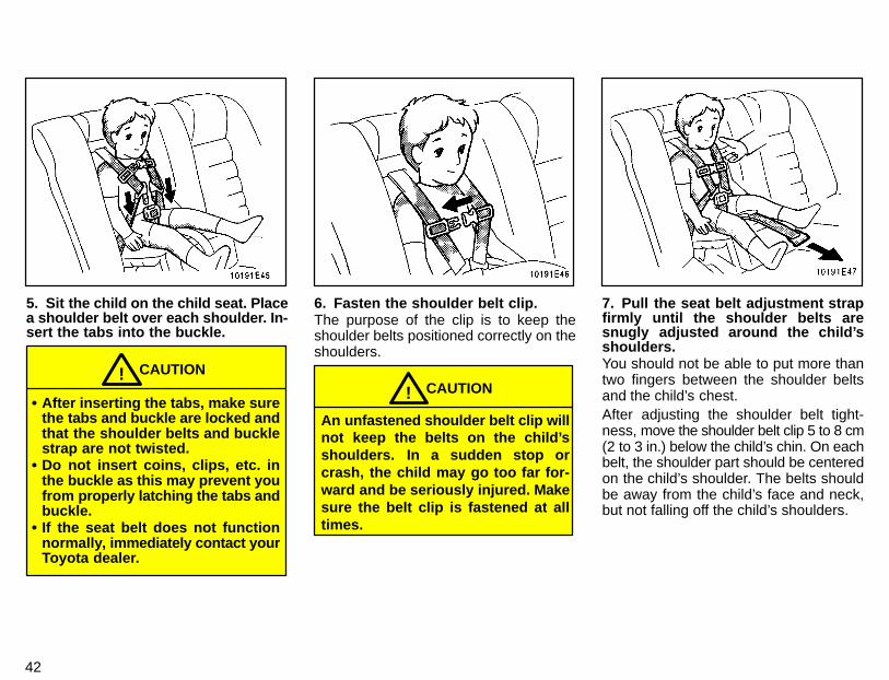
5. Sit the child on the child seat. Placea shoulder belt over each shoulder. In-sert the tabs into the buckle.
CAUTION!
� After inserting the tabs, make surethe tabs and buckle are locked andthat the shoulder belts and bucklestrap are not twisted.
� Do not insert coins, clips, etc. inthe buckle as this may prevent youfrom pr operly latching the tabs andbuckle.
� If the seat belt does not functionnormally, immediately contact yourToyota dealer.
6. Fasten the shoulder belt clip.The purpose of the clip is to keep theshoulder belts positioned correctly on theshoulders.
CAUTION!
An unfastened shoulder belt clip willnot keep the belts on the child’sshoulders. In a sudden stop orcrash, the child may go too far for-ward and be seriously injured. Makesure the belt clip is fastened at alltimes.
7. Pull the seat belt adjustment strapfirmly until the shoulder belts aresnugly adjusted around the child’sshoulders.You should not be able to put more thantwo fingers between the shoulder beltsand the child’s chest.After adjusting the shoulder belt tight-ness, move the shoulder belt clip 5 to 8 cm(2 to 3 in.) below the child’s chin. On eachbelt, the shoulder part should be centeredon the child’s shoulder. The belts shouldbe away from the child’s face and neck,but not falling off the child’s shoulders.

43
8. To release the child from the seatbelts, compress the shoulder belt clip,then press the buckle release button.Move both belts off the child’s shoulders.
9. To store the built-in child restraint,fasten the shoulder belt clip and returnthe seat belt buckle using the fastenertapes. Fold up the seat belt adjustmentstrap in the seat. Then raise the seatcushion and return the head pad byengaging the fastener tapes whilepressing the child restraint cushionand head pad firmly.
A child restraint system for a smallchild or baby must itself be restrainedon the seat with either the lap belt orthe lap portion of the lap/shoulderbelt.The child restraint system should conformto the size of the child and properly fit thevehicle seat. For greater safety, the childrestraint system should be installed in therear seat. According to accident statistics,children are safer when properly re-strained in the rear seat than in the frontseat.When installing a child restraint system,follow the instructions provided by themanufacturer of the system. General di-rections are also provided under the fol-lowing illustrations.
CAUTION!
After installing the child restraintsystem, make sure it is secured inplace. If it is not restrained securely,it may cause injury to the child in theevent of a sudden stop or accident.
When not using the child restraint system,keep it secured with the seat belt or placeit somewhere other than in passengercompartment. This will prevent it injuringpassengers in the event of a sudden stopor accident.
-Child restraint system
44
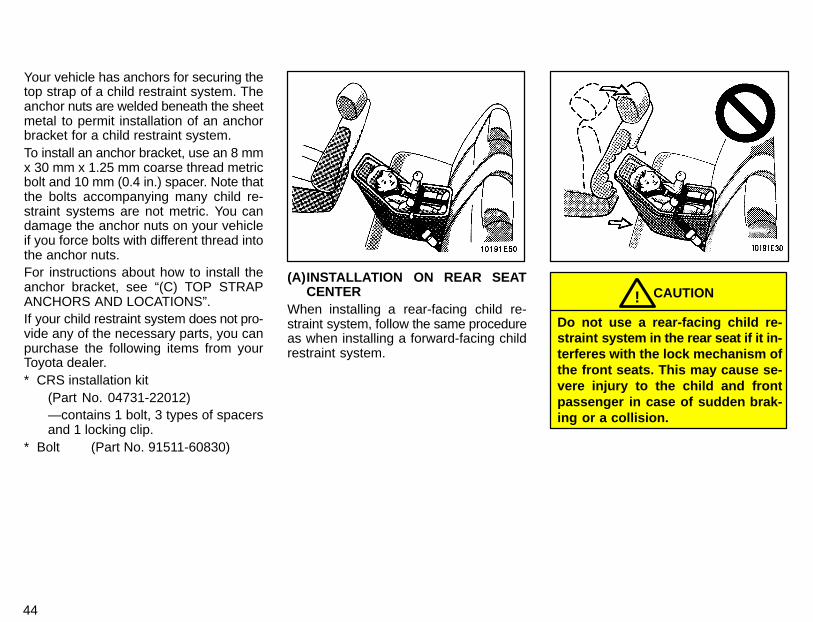
Your vehicle has anchors for securing thetop strap of a child restraint system. Theanchor nuts are welded beneath the sheetmetal to permit installation of an anchorbracket for a child restraint system.To install an anchor bracket, use an 8 mmx 30 mm x 1.25 mm coarse thread metricbolt and 10 mm (0.4 in.) spacer. Note thatthe bolts accompanying many child re-straint systems are not metric. You candamage the anchor nuts on your vehicleif you force bolts with different thread intothe anchor nuts.For instructions about how to install theanchor bracket, see “(C) TOP STRAPANCHORS AND LOCATIONS”.If your child restraint system does not pro-vide any of the necessary parts, you canpurchase the following items from yourToyota dealer.* CRS installation kit
(Part No. 04731-22012)—contains 1 bolt, 3 types of spacersand 1 locking clip.
* Bolt (Part No. 91511-60830)
(A)INSTALLATION ON REAR SEATCENTER
When installing a rear-facing child re-straint system, follow the same procedureas when installing a forward-facing childrestraint system.
CAUTION!
Do not use a rear-facing child re-straint system in the rear seat if it in-terferes with the lock mechanism ofthe front seats. This may cause se-vere injury to the child and frontpassenger in case of sudden brak-ing or a collision.
45
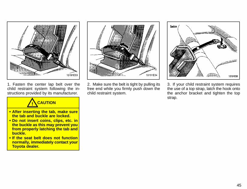
1. Fasten the center lap belt over thechild restraint system following the in-structions provided by its manufacturer.
CAUTION!
� After inserting the tab, make surethe tab and buckle are locked.
� Do not insert coins, clips, etc. inthe buckle as this may prevent youfrom properly latching the tab andbuckle.
� If the seat belt does not functionnormally, i mmediately contact yourToyota dealer.
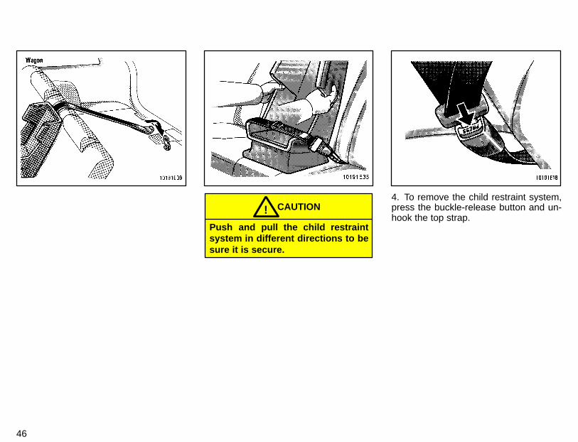
2. Make sure the belt is tight by pulling itsfree end while you firmly push down thechild restraint system.
3. If your child restraint system requiresthe use of a top strap, latch the hook ontothe anchor bracket and tighten the topstrap.
46
CAUTION!Push and pull the child restraintsystem in different directions to besure it is secure.
4. To remove the child restraint system,press the buckle-release button and un-hook the top strap.
47
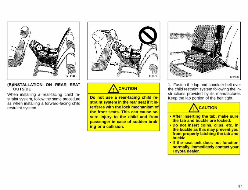
(B)INSTALLATION ON REAR SEATOUTSIDE
When installing a rear-facing child re-straint system, follow the same procedureas when installing a forward-facing childrestraint system.
CAUTION!Do not use a rear-facing child re-straint system in the rear seat if it in-terferes with the lock mechanism ofthe front seats. This can cause se-vere injury to the child and frontpassenger in case of sudden brak-ing or a collision.
1. Fasten the lap and shoulder belt overthe child restraint system following the in-structions provided by its manufacturer.Keep the lap portion of the belt tight.
CAUTION!� After inserting the tab, make sure
the tab and buckle are locked.� Do not insert coins, clips, etc. in
the buckle as this may prevent youfrom properly latching the tab andbuckle.
� If the seat belt does not functionnormally, immediately contact yourToyota dealer.
48
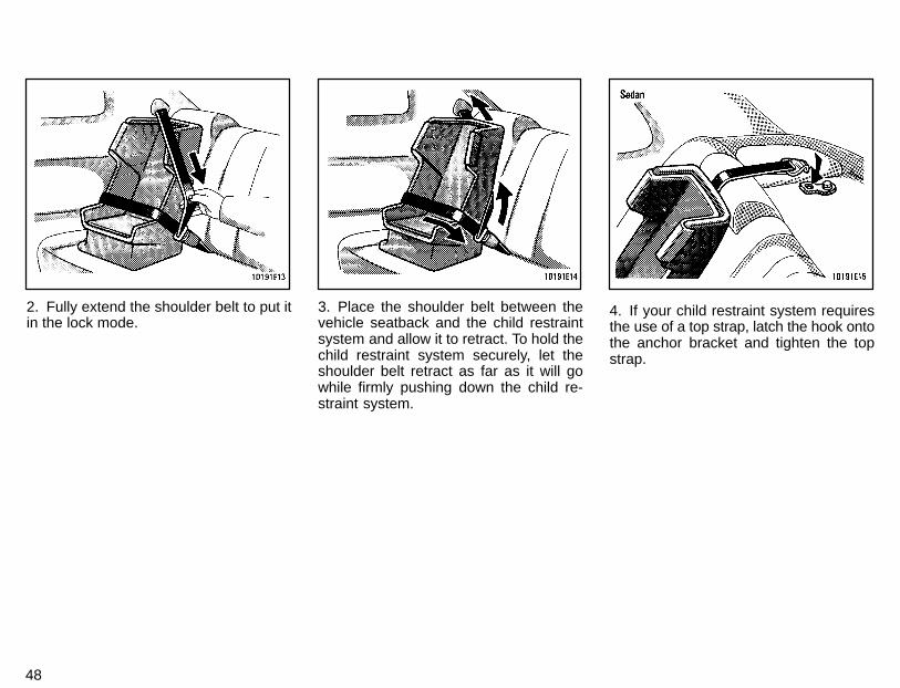
2. Fully extend the shoulder belt to put itin the lock mode.
3. Place the shoulder belt between thevehicle seatback and the child restraintsystem and allow it to retract. To hold thechild restraint system securely, let theshoulder belt retract as far as it will gowhile firmly pushing down the child re-straint system.
4. If your child restraint system requiresthe use of a top strap, latch the hook ontothe anchor bracket and tighten the topstrap.
49
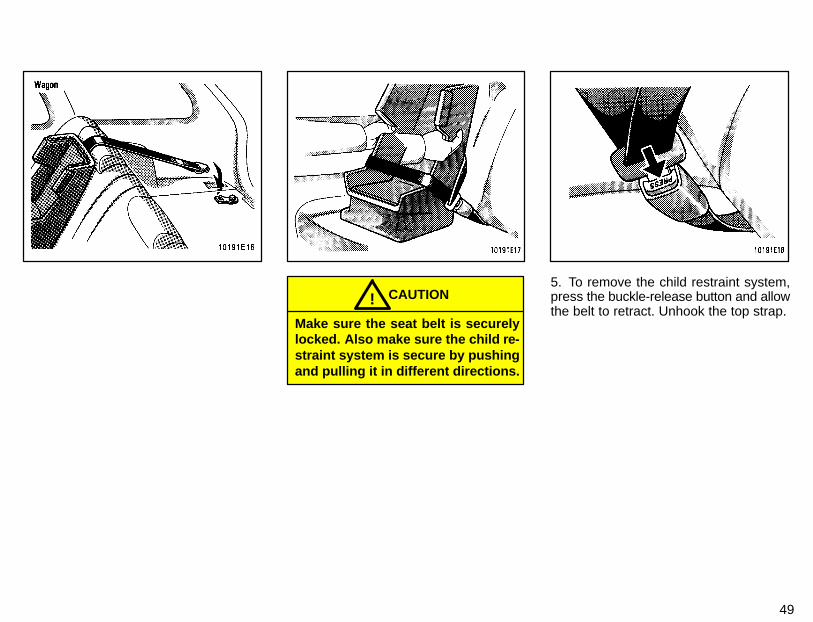
CAUTION!Make sure the seat belt is securelylocked. Also make sure the child re-straint system is secure by pushingand pulling it in different directions.
5. To remove the child restraint system,press the buckle-release button and allowthe belt to retract. Unhook the top strap.
50
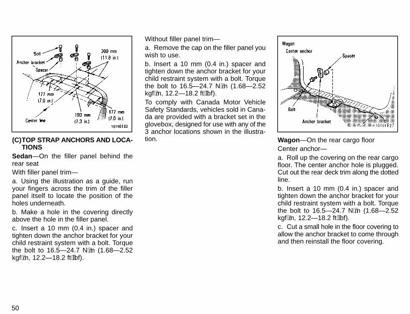
(C)TOP STRAP ANCHORS AND LOCA-TIONS
Sedan—On the filler panel behind therear seatWith filler panel trim—a. Using the illustration as a guide, runyour fingers across the trim of the fillerpanel itself to locate the position of theholes underneath.b. Make a hole in the covering directlyabove the hole in the filler panel.c. Insert a 10 mm (0.4 in.) spacer andtighten down the anchor bracket for yourchild restraint system with a bolt. Torquethe bolt to 16.5—24.7 N⋅m (1.68—2.52kgf⋅m, 12.2—18.2 ft⋅lbf).
Without filler panel trim—a. Remove the cap on the filler panel youwish to use.b. Insert a 10 mm (0.4 in.) spacer andtighten down the anchor bracket for yourchild restraint system with a bolt. Torquethe bolt to 16.5—24.7 N⋅m (1.68—2.52kgf⋅m, 12.2—18.2 ft⋅lbf).To comply with Canada Motor VehicleSafety Standards, vehicles sold in Cana-da are provided with a bracket set in theglovebox, designed for use with any of the3 anchor locations shown in the illustra-tion. Wagon —On the rear cargo floor
Center anchor—a. Roll up the covering on the rear cargofloor. The center anchor hole is plugged.Cut out the rear deck trim along the dottedline.b. Insert a 10 mm (0.4 in.) spacer andtighten down the anchor bracket for yourchild restraint system with a bolt. Torquethe bolt to 16.5—24.7 N⋅m (1.68—2.52kgf⋅m, 12.2—18.2 ft⋅lbf).c. Cut a small hole in the floor covering toallow the anchor bracket to come throughand then reinstall the floor covering.
51
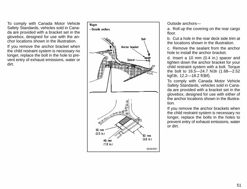
To comply with Canada Motor VehicleSafety Standards, vehicles sold in Cana-da are provided with a bracket set in theglovebox, designed for use with the an-chor locations shown in the illustration.If you remove the anchor bracket whenthe child restraint system is necessary nolonger, replace the bolt in the hole to pre-vent entry of exhaust emissions, water ordirt.
Outside anchors—a. Roll up the covering on the rear cargofloor.b. Cut a hole in the rear deck side trim atthe locations shown in the illustration.c. Remove the sealant from the anchorhole to install the anchor bracket.d. Insert a 10 mm (0.4 in.) spacer andtighten down the anchor bracket for yourchild restraint system with a bolt. Torquethe bolt to 16.5—24.7 N⋅m (1.68—2.52kgf⋅m, 12.2—18.2 ft⋅lbf).To comply with Canada Motor VehicleSafety Standards, vehicles sold in Cana-da are provided with a bracket set in theglovebox, designed for use with either ofthe anchor locations shown in the illustra-tion.If you remove the anchor brackets whenthe child restraint system is necessary nolonger, replace the bolts in the holes toprevent entry of exhaust emissions, wateror dirt.
52
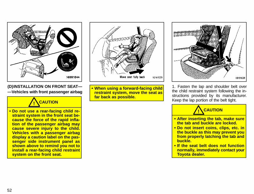
(D)INSTALLATION ON FRONT SEAT——Vehicles with front passenger airbag
CAUTION!� Do not use a rear-facing child re-
straint system in the front seat be-cause the force of the rapid infla-tion of the passenger airbag maycause severe injury to the child.Vehicles with a passenger airbagdisplay a caution label on the pas-senger side instrument panel asshown above to remind you not toinstall a rear-facing child restraintsystem on the front seat.
� When using a forward-facing childrestraint system, move the seat asfar back as possible.
1. Fasten the lap and shoulder belt overthe child restraint system following the in-structions provided by its manufacturer.Keep the lap portion of the belt tight.
CAUTION!� After inserting the tab, make sure
the tab and buckle are locked.� Do not insert coins, clips, etc. in
the buckle as this may prevent youfrom properly latching the tab andbuckle.
� If the seat belt does not functionnormally, immediately contact yourToyota dealer.
53
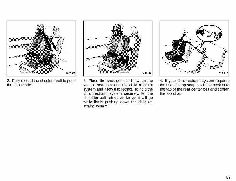
2. Fully extend the shoulder belt to put inthe lock mode.
3. Place the shoulder belt between thevehicle seatback and the child restraintsystem and allow it to retract. To hold thechild restraint system securely, let theshoulder belt retract as far as it will gowhile firmly pushing down the child re-straint system.
4. If your child restraint system requiresthe use of a top strap, latch the hook ontothe tab of the rear center belt and tightenthe top strap.
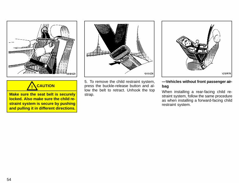
54
CAUTION!Make sure the seat belt is securelylocked. Also make sure the child re-straint system is secure by pushingand pulling it in different directions.
5. To remove the child restraint system,press the buckle-release button and al-low the belt to retract. Unhook the topstrap.
—Vehicles without front passenger air-bagWhen installing a rear-facing child re-straint system, follow the same procedureas when installing a forward-facing childrestraint system.
55
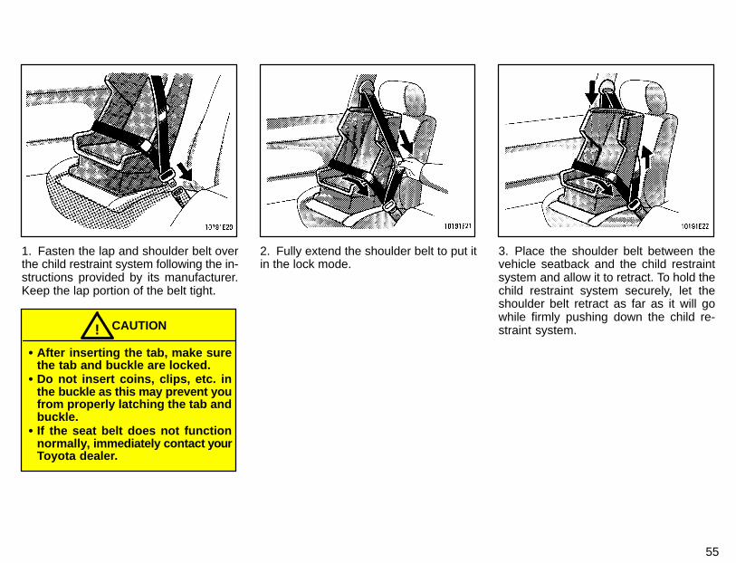
1. Fasten the lap and shoulder belt overthe child restraint system following the in-structions provided by its manufacturer.Keep the lap portion of the belt tight.
CAUTION!
� After inserting the tab, make surethe tab and buckle are locked.
� Do not insert coins, clips, etc. inthe buckle as this may prevent youfrom properly latching the tab andbuckle.
� If the seat belt does not functionnormally, immediately contact yourToyota dealer.
2. Fully extend the shoulder belt to put itin the lock mode.
3. Place the shoulder belt between thevehicle seatback and the child restraintsystem and allow it to retract. To hold thechild restraint system securely, let theshoulder belt retract as far as it will gowhile firmly pushing down the child re-straint system.
56
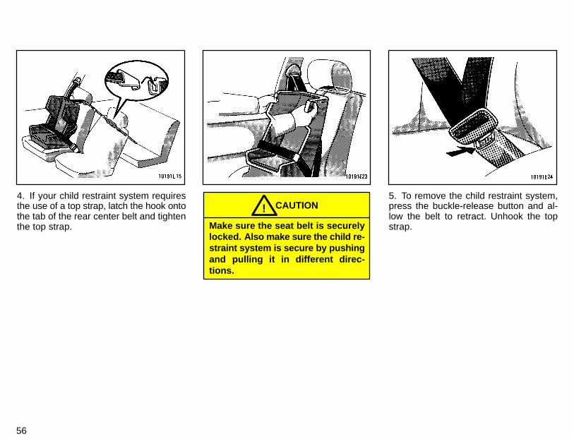
4. If your child restraint system requiresthe use of a top strap, latch the hook ontothe tab of the rear center belt and tightenthe top strap.
CAUTION!Make sure the seat belt is securelylocked. Also make sure the child re-straint system is secure by pushingand pulling it in different direc-tions.
5. To remove the child restraint system,press the buckle-release button and al-low the belt to retract. Unhook the topstrap.
57
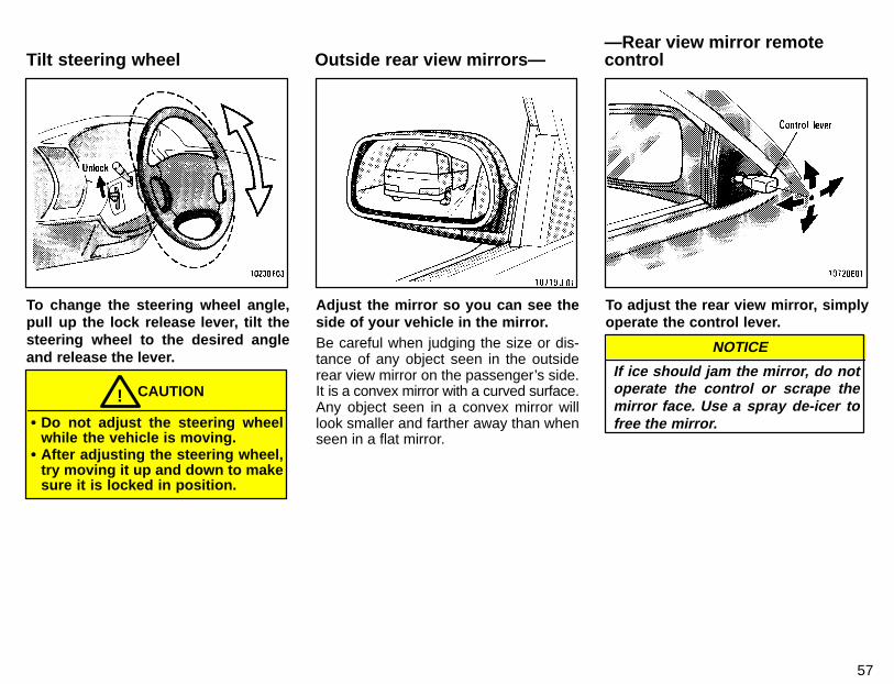
To change the steering wheel angle,pull up the lock release lever, tilt thesteering wheel to the desired angleand release the lever.
CAUTION!� Do not adjust the steering wheel
while the vehicle is moving.� After adjusting the steering wheel,
try moving it up and down to makesure it is locked in position.
Adjust the mirror so you can see theside of your vehicle in the mirror.Be careful when judging the size or dis-tance of any object seen in the outsiderear view mirror on the passenger’s side.It is a convex mirror with a curved surface.Any object seen in a convex mirror willlook smaller and farther away than whenseen in a flat mirror.
To adjust the rear view mirror, simplyoperate the control lever.
If ice should jam the mirror, do notoperate the control or scrape themirror face. Use a spray de-icer tofree the mirror.
NOTICE
Tilt steering wheel Outside rear view mirrors——Rear view mirror remotecontrol
58
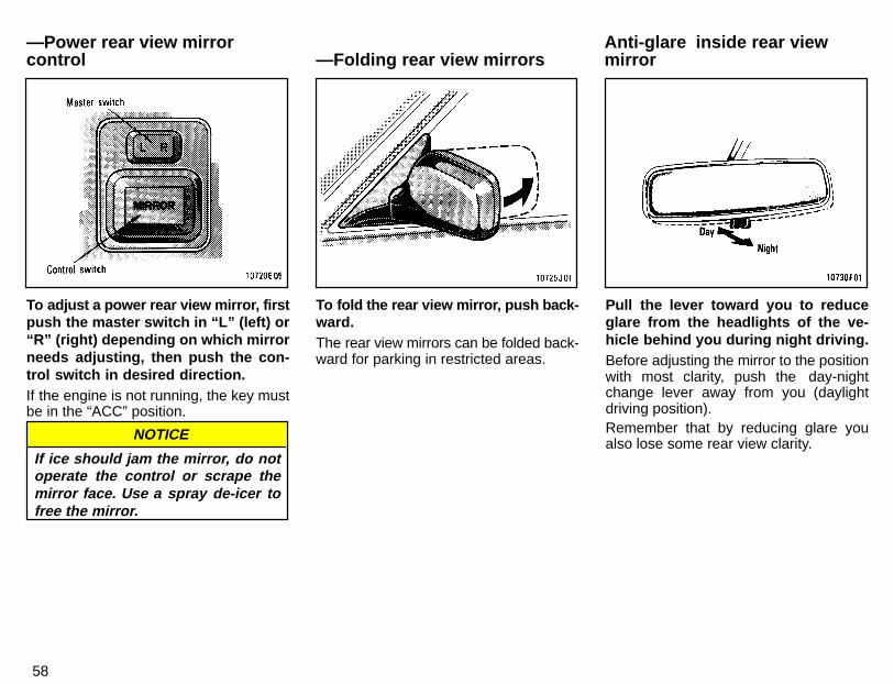
To adjust a power rear view mirror, firstpush the master switch in “L” (left) or“R” (right) depending on which mirrorneeds adjusting, then push the con-trol switch in desired direction.If the engine is not running, the key mustbe in the “ACC” position.
If ice should jam the mirror, do notoperate the control or scrape themirror face. Use a spray de-icer tofree the mirror.
NOTICE
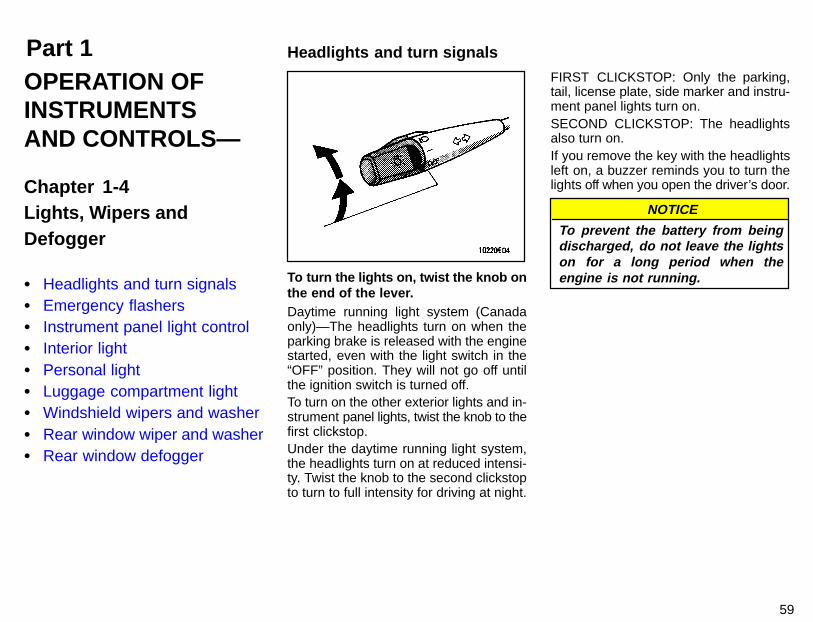
To fold the rear view mirror, push back-ward.The rear view mirrors can be folded back-ward for parking in restricted areas.
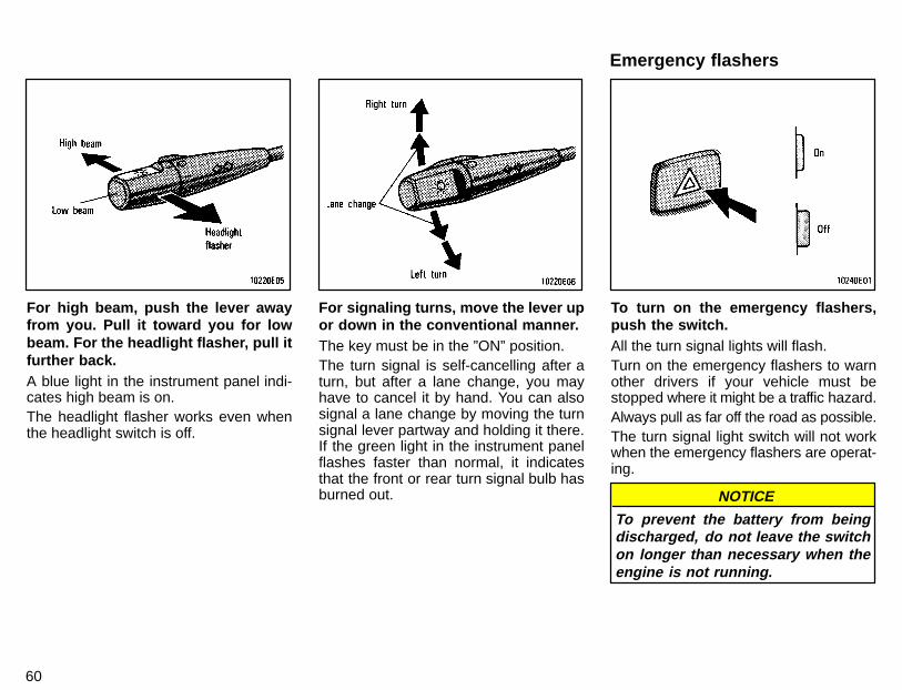
Pull the lever toward you to reduceglare from the headlights of the ve-hicle behind you during night driving.Before adjusting the mirror to the positionwith most clarity, push the day-nightchange lever away from you (daylightdriving position).Remember that by reducing glare youalso lose some rear view clarity.
Anti-glare inside rear viewmirror—Folding rear view mirrors
—Power rear view mirrorcontrol
Part 1 Headlights and turn signals
59
OPERATION OFINSTRUMENTSAND CONTROLS—
Chapter 1-4Lights, Wipers andDefogger
� Headlights and turn signals� Emergency flashers� Instrument panel light control� Interior light� Personal light� Luggage compartment light� Windshield wipers and washer� Rear window wiper and washer� Rear window defogger
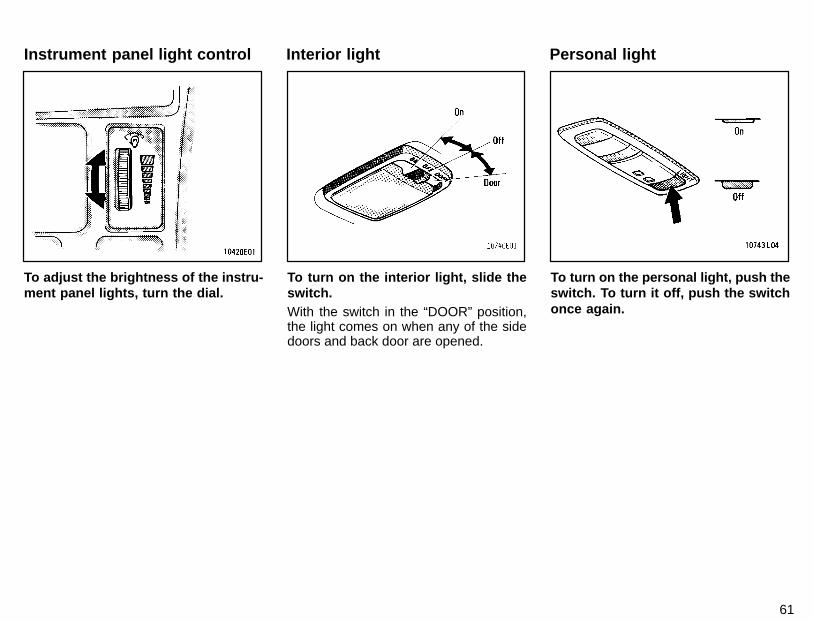
To turn the lights on, twist the knob onthe end of the lever.Daytime running light system (Canadaonly)—The headlights turn on when theparking brake is released with the enginestarted, even with the light switch in the“OFF” position. They will not go off untilthe ignition switch is turned off.To turn on the other exterior lights and in-strument panel lights, twist the knob to thefirst clickstop.Under the daytime running light system,the headlights turn on at reduced intensi-ty. Twist the knob to the second clickstopto turn to full intensity for driving at night.
FIRST CLICKSTOP: Only the parking,tail, license plate, side marker and instru-ment panel lights turn on.SECOND CLICKSTOP: The headlightsalso turn on.If you remove the key with the headlightsleft on, a buzzer reminds you to turn thelights off when you open the driver’s door.
NOTICE
To prevent the battery from beingdischarged, do not leave the lightson for a long period when theengine is not running.
60
For high beam, push the lever awayfrom you. Pull it toward you for lowbeam. For the headlight flasher, pull itfurther back.A blue light in the instrument panel indi-cates high beam is on.The headlight flasher works even whenthe headlight switch is off.
For signaling turns, move the lever upor down in the conventional manner.The key must be in the ”ON” position.The turn signal is self-cancelling after aturn, but after a lane change, you mayhave to cancel it by hand. You can alsosignal a lane change by moving the turnsignal lever partway and holding it there.If the green light in the instrument panelflashes faster than normal, it indicatesthat the front or rear turn signal bulb hasburned out.
To turn on the emergency flashers,push the switch.All the turn signal lights will flash.Turn on the emergency flashers to warnother drivers if your vehicle must bestopped where it might be a traffic hazard.Always pull as far off the road as possible.The turn signal light switch will not workwhen the emergency flashers are operat-ing.
NOTICE
To prevent the battery from beingdischarged, do not leave the switchon longer than necessary when theengine is not running.
Emergency flashers
61
To adjust the brightness of the instru-ment panel lights, turn the dial.
To turn on the interior light, slide theswitch.With the switch in the “DOOR” position,the light comes on when any of the sidedoors and back door are opened.
To turn on the personal light, push theswitch. To turn it off, push the switchonce again.
Instrument panel light control Interior light Personal light

62
To turn the luggage compartment lighton, open the back door and push theswitch. Closing the back door will turnthe light off.
To turn the wipers on, move the lever.To make the washer squirt, push thebutton on the end of the lever.The key must be in the ”ON” position.The wipers will operate at intervals whenthe lever is in the ”INT” position.If the washer does not work, check to seewhether the washer tank is empty. For in-formation on adding washer fluid, see“Adding washer fluid” in Chapter 7-3.In cold weather, warm the windshield withthe defroster before using the washer.This will help prevent icing, which couldblock your vision.
NOTICE
Do not operate the wipers if thewindshield is dry. It may scratch theglass.
Luggage compartment light(wagon)
Windshield wipers and washer(intermittent type withoutinterval adjuster)

63
To turn the wipers on, move the lever.To make the washer squirt, push thebutton on the end of the lever.The key must be in the “ON” position.The wipers will operate at intervals whenthe lever is in the “INT” position. With thelever in this position, the wipers can be ad-justed to operate at intervals of 3 to 10 se-conds depending on the interval adjustersetting between “S” and “F”.Also, the wipers will automatically operatea couple of times after the washer squirtseven with the lever in the “OFF” position.
If the washer does not work, check to seewhether the washer tank is empty. For in-formation on adding washer fluid, see“Adding washer fluid” in Chapter 7-3.In cold weather, warm the windshield withthe defroster before using the washer.This will help prevent icing, which couldblock your vision.
NOTICE
Do not operate the wipers if thewindshield is dry. It may scratch theglass.
To turn the wipers on, move the lever.To make the washer squirt, push thebutton on the end of the lever.The key must be in the “ON” position.If a single wipe is desired in mist, push thelever to the “MIST” position and release it.If the washer does not work, check to seewhether the washer tank is empty. For in-formation on adding washer fluid, see“Adding washer fluid” in Chapter 7-3.In cold weather, warm the windshield withthe defroster before using the washer.This will help prevent icing, which couldblock your vision.
Windshield wipers and washer(intermittent type with intervaladjuster)
Windshield wipers and washer(mist type)

64
NOTICE
Do not operate the wipers if thewindshield is dry. It may scratch theglass.
To turn the rear wiper and washer on,twist the knob at the end of the lever.The key must be in the “ON” position.The wipers will operate at intervals whenthe lever is in the “INT” position.The washer squirts at the two marked knobpositions. The knob will automatically re-turn from these positions when it is re-leased.If the washer does not work, check to seewhether the washer tank is empty. For in-formation on adding washer fluid, see“Adding washer fluid” in Chapter 7-3.
NOTICE
Do not operate the rear wiper if therear window is dry. It may scratchthe glass.
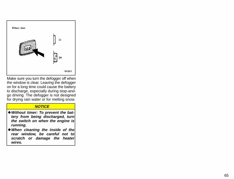
To defog or defrost the rear window,push the switch.The key must be in the “ON” position.The thin heater wires on the inside of therear window will quickly clear the sur-faces. An indicator light will illuminate toindicate the defogger is operating.Push the switch once again to turn the de-fogger off.With timer: The system will automaticallyshut off after the defogger has operatedabout 15 minutes.
Rear window defoggerRear window wiper and washer
65
Make sure you turn the defogger off whenthe window is clear. Leaving the defoggeron for a long time could cause the batteryto discharge, especially during stop-and-go driving. The defogger is not designedfor drying rain water or for melting snow.
NOTICE
�Without timer: To prevent the bat-tery from being discharged, turnthe switch on when the engine isrunning.
�When cleaning the inside of therear window, be careful not toscratch or damage the heaterwires.

66
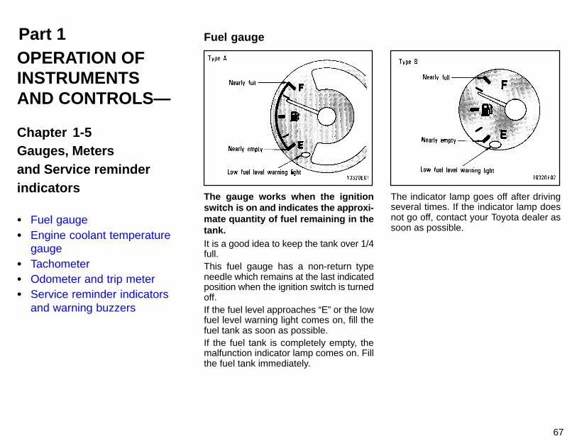
Part 1 Fuel gauge
67
OPERATION OFINSTRUMENTSAND CONTROLS—
Chapter 1-5Gauges, Metersand Service reminderindicators
� Fuel gauge� Engine coolant temperature
gauge� Tachometer� Odometer and trip meter� Service reminder indicators
and warning buzzers
The gauge works when the ignitionswitch is on and indicates the approxi-mate quantity of fuel remaining in thetank.It is a good idea to keep the tank over 1/4full.This fuel gauge has a non-return typeneedle which remains at the last indicatedposition when the ignition switch is turnedoff.If the fuel level approaches “E” or the lowfuel level warning light comes on, fill thefuel tank as soon as possible.If the fuel tank is completely empty, themalfunction indicator lamp comes on. Fillthe fuel tank immediately.
The indicator lamp goes off after drivingseveral times. If the indicator lamp doesnot go off, contact your Toyota dealer assoon as possible.
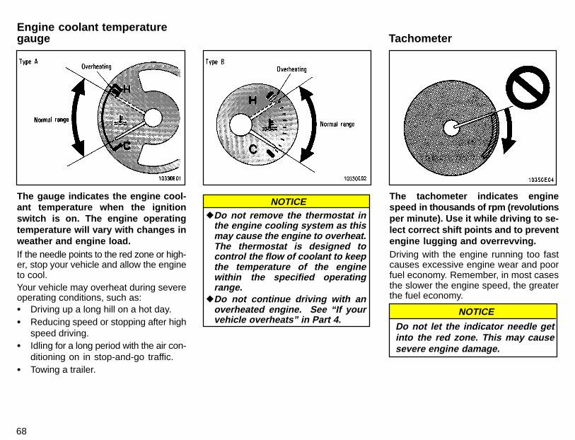
68
The gauge indicates the engine cool-ant temperature when the ignitionswitch is on. The engine operatingtemperature will vary with changes inweather and engine load.If the needle points to the red zone or high-er, stop your vehicle and allow the engineto cool.Your vehicle may overheat during severeoperating conditions, such as:� Driving up a long hill on a hot day.� Reducing speed or stopping after high
speed driving.� Idling for a long period with the air con-
ditioning on in stop-and-go traffic.� Towing a trailer.
NOTICE�Do not remove the thermostat in
the engine cooling system as thismay cause the engine to overheat.The thermostat is designed tocontrol the flow of coolant to keepthe temperature of the enginewithin the specified operatingrange.
�Do not continue driving with anoverheated engine. See “If yourvehicle overheats” in Part 4.
The tachometer indicates enginespeed in thousands of rpm (revolutionsper minute). Use it while driving to se-lect correct shift points and to preventengine lugging and overrevving.Driving with the engine running too fastcauses excessive engine wear and poorfuel economy. Remember, in most casesthe slower the engine speed, the greaterthe fuel economy.
NOTICE
Do not let the indicator needle getinto the red zone. This may causesevere engine damage.
TachometerEngine coolant temperaturegauge
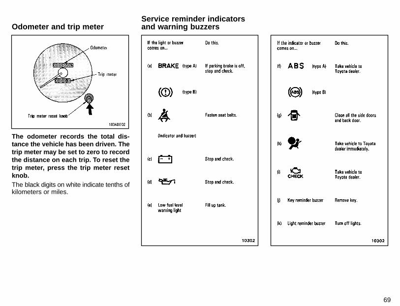
69
The odometer records the total dis-tance the vehicle has been driven. Thetrip meter may be set to zero to recordthe distance on each trip. To reset thetrip meter, press the trip meter resetknob.The black digits on white indicate tenths ofkilometers or miles.
Odometer and trip meterService reminder indicatorsand warning buzzers

70
(a) Brake System Warning LightThis light has the following functions:Parking brake reminderIf this light is on, make sure the parkingbrake is fully released. The light should gooff.Low brake fluid level warningIf this light comes on and stays on whileyou are driving, slow down and pull off theroad. Then stop the vehicle carefully.There may be a problem somewhere inthe brake system. Check the fluid level ofthe see-through reservoir.To make sure the parking brake has notcaused the warning light to come on,check to see that the parking brake is fullyreleased.If the brake fluid level is low...At a safe place, test your brakes by start-ing and stopping.� If you judge that the brakes still work
adequately, drive cautiously to yournearest dealer or shop for repairs.
� If the brakes are not working, have thevehicle towed in for repairs. (For tow-ing information, see Part 4.)
It is dangerous to continue drivingnormally when the brake fluid levelis low.
CAUTION!
If the brake fluid level is correct...Have the warning system checked byyour Toyota dealer.(b) Seat Belt Reminder Light and BuzzerOnce the ignition key is turned to “ON” or“START”, the reminder light and buzzercome on if the driver’s seat belt is not fas-tened. Unless the driver fastens the belt,the light stays on and the buzzer stops af-ter about 4 to 8 seconds.(c) Discharge Warning LightThis light warns that the battery is beingdischarged.If it comes on while you are driving, thereis a problem somewhere in the chargingsystem.The engine ignition will continue to operate,however, until the battery is discharged.Turn off the air conditioning, blower, radio,etc., and drive directly to the nearest Toyotadealer or repair shop.
NOTICEDo not continue driving if the enginedrive belt is broken or loose.
(d) Low Oil Pressure Warning LightThis light warns that the engine oil pres-sure is too low.If it flickers or stays on while you are driv-ing, pull off the road to a safe place andstop the engine immediately. Call a Toyotadealer or qualified repair shop for assis-tance.The light may occasionally flicker whenthe engine is idling or it may come on brief-ly after a hard stop. There is no cause forconcern if it then goes out when the en-gine is accelerated slightly.The light may come on when the oil levelis extremely low. It is not designed to indi-cate low oil level, and the oil level must bechecked using the level dipstick.
NOTICE
Do not drive the vehicle with thewarning light on—even for oneblock. It may ruin the engine.
(e) Low Fuel Level Warning LightThis light comes on when the fuel level inthe tank becomes nearly empty. Fill up thetank as soon as possible.
71
(f) “ABS” Warning LightThis light warns that there is a problemsomewhere in your anti-lock brake sys-tem.If the light comes on while you are driving,have your vehicle checked by your Toyotadealer as soon as possible.The light will come on when the ignitionkey is turned to the “ON” position. Afterabout 3 seconds, the light will go off.When the “ABS” warning light is on (andthe brake system warning light is off), thebrake system operates conventionally butwithout anti-lock function.(g) Open Door Warning LightThis light remains on until all the sidedoors and back door are completelyclosed.(h) SRS Airbag Warning LightThis light will come on when the igni-tion key is turned to the “ACC” or “ON”position. After about 6 seconds, thelight will go off. This means the airbagsystem is operating properly.The warning light system monitors the air-bag sensor assembly, inflators, warninglight, interconnecting wiring and powersources.
If either of the following conditions occurs,this indicates a malfunction somewhere inthe parts monitored by the warning lightsystem. Contact your Toyota dealer assoon as possible to service the vehicle.� The light does not come on when the
ignition key is turned to the “ACC” or“ON” position or remains on.
� The light comes on while driving.(i) Malfunction Indicator LampThis lamp comes on in the followingcases.a. The fuel tank is completely empty.(See “Fuel gauge” in Chapter 1-5 for in-structions.)b. There is a problem somewhere in yourengine or automatic transmission electri-cal system.If it comes on while you are driving in caseb, have your vehicle checked/repaired byyour Toyota dealer as soon as possible.(j) Key Reminder BuzzerThis buzzer reminds you to remove thekey when you open the driver’s door withthe ignition key in the “ACC” or “LOCK”position.
(k) Light Reminder BuzzerThis buzzer will sound if the driver’s dooris opened with the key removed from theignition switch and the headlight switchleft on.CHECKING SERVICE REMINDER INDI-CATORS (except the low fuel levelwarning light)1. Apply the parking brake.2. Open one of the side doors or back door.The open door warning light should comeon.3. Close the door.The open door warning light should go off.4. Turn the ignition key to “ACC”.The SRS airbag warning light shouldcome on. It goes off after about 6 sec-onds.5. Turn the ignition key to “ON”, but do notstart the engine.All the service reminder indicators exceptthe open door warning light and SRS air-bag warning light should come on. The“ABS” warning light goes off after about 3seconds.If any service reminder indicators or warn-ing buzzer do not function as describedabove, either the bulb is burned out or thecircuit is in need of repair. Have it checkedby your Toyota dealer as soon as pos-sible.

72
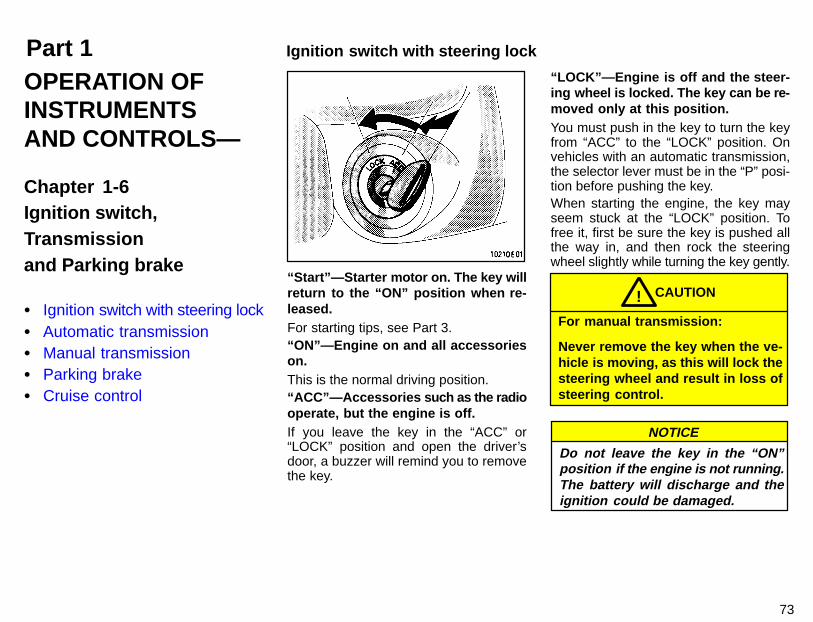
Part 1 Ignition switch with steering lock
73
OPERATION OFINSTRUMENTSAND CONTROLS—
Chapter 1-6Ignition switch,Transmissionand Parking brake
� Ignition switch with steering lock� Automatic transmission� Manual transmission� Parking brake� Cruise control
“Start”—Starter m otor on. The key willreturn to the “ON” position when re-leased.For starting tips, see Part 3.“ON”—Engine on and all accessorieson.This is the normal driving position.“ACC”—Accessories such as the radiooperate, but the engine is off.If you leave the key in the “ACC” or“LOCK” position and open the driver’sdoor, a buzzer will remind you to removethe key.
“LOCK”—Engine is off and the steer-ing wheel is locked. The key can be re-moved only at this position.You must push in the key to turn the keyfrom “ACC” to the “LOCK” position. Onvehicles with an automatic transmission,the selector lever must be in the “P” posi-tion before pushing the key.When starting the engine, the key mayseem stuck at the “LOCK” position. Tofree it, first be sure the key is pushed allthe way in, and then rock the steeringwheel slightly while turning the key gently.
For manual transmission:
Never remove the key when the ve-hicle is moving, as this will lock thesteering wheel and result in loss ofsteering control.
CAUTION!
NOTICE
Do not leave the key in the “ON”position if the engine is not running.The battery will discharge and theignition could be damaged.
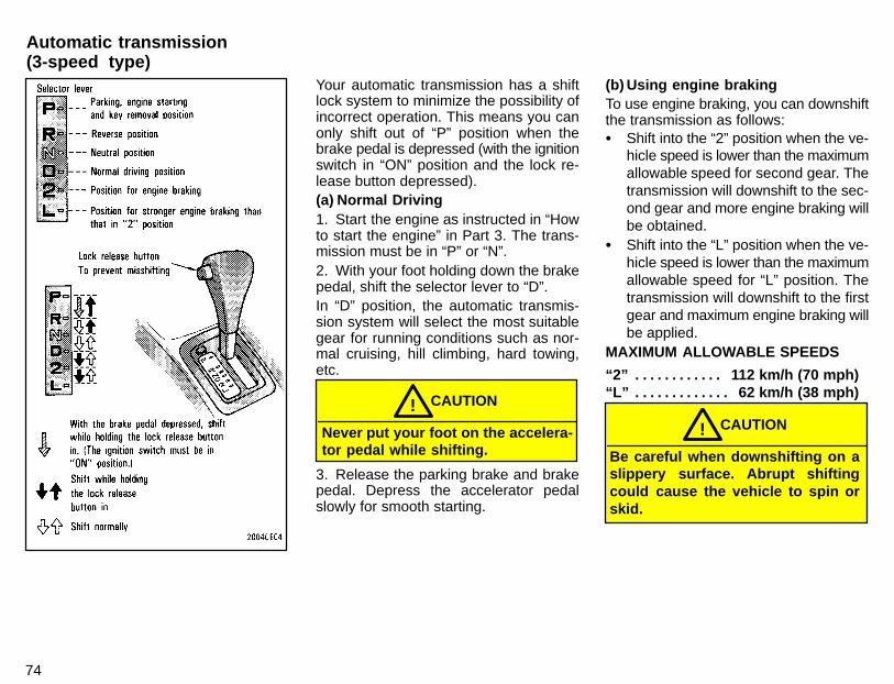
74
Your automatic transmission has a shiftlock system to minimize the possibility ofincorrect operation. This means you canonly shift out of “P” position when thebrake pedal is depressed (with the ignitionswitch in “ON” position and the lock re-lease button depressed).(a) Normal Driving1. Start the engine as instructed in “Howto start the engine” in Part 3. The trans-mission must be in “P” or “N”.2. With your foot holding down the brakepedal, shift the selector lever to “D”.In “D” position, the automatic transmis-sion system will select the most suitablegear for running conditions such as nor-mal cruising, hill climbing, hard towing,etc.
Never put your foot on the accelera-tor pedal while shifting.
CAUTION!
3. Release the parking brake and brakepedal. Depress the accelerator pedalslowly for smooth starting.
(b) Using engine brakingTo use engine braking, you can downshiftthe transmission as follows:� Shift into the “2” position when the ve-
hicle speed is lower than the maximumallowable speed for second gear. Thetransmission will downshift to the sec-ond gear and more engine braking willbe obtained.
� Shift into the “L” position when the ve-hicle speed is lower than the maximumallowable speed for “L” position. Thetransmission will downshift to the firstgear and maximum engine braking willbe applied.
MAXIMUM ALLOWABLE SPEEDS
“2” 112 km/h (70 mph). . . . . . . . . . . . “L” 62 km/h (38 mph). . . . . . . . . . . . .
Be careful when downshifting on aslippery surface. Abrupt shiftingcould cause the vehicle to spin orskid.
CAUTION!
Automatic transmission(3-speed type)
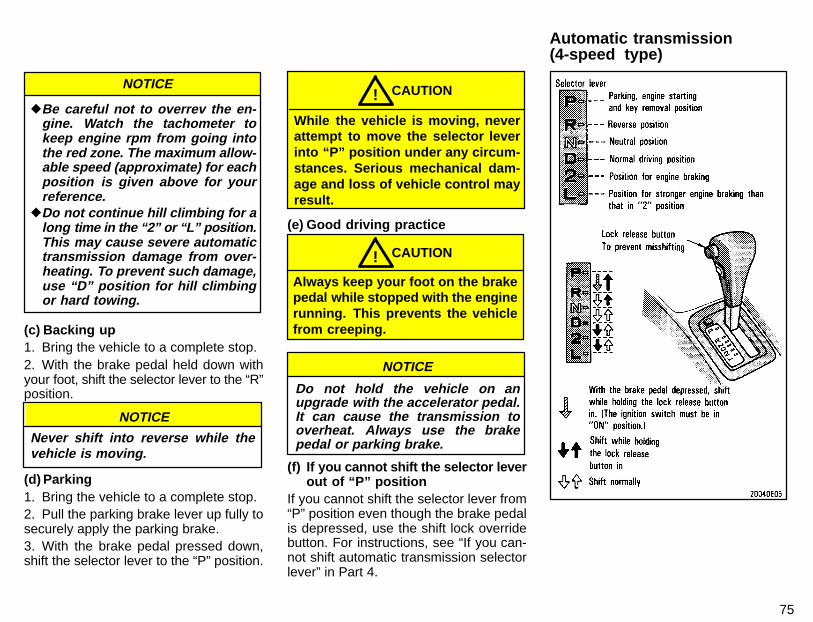
75
NOTICE
�Be careful not to overrev the en-gine. Watch the tachometer tokeep engine rpm from going intothe red zone. The maximum allow-able speed (approximate) for eachposition is given above for yourreference.
�Do not continue hill climbing for along time in the “2” or “L” position.This may cause severe automatictransmission damage from over-heating. To prevent such damage,use “D” position for hill climbingor hard towing.
(c) Backing up1. Bring the vehicle to a complete stop.2. With the brake pedal held down withyour foot, shift the selector lever to the “R”position.
NOTICE
Never shift into reverse while thevehicle is moving.
(d) Parking1. Bring the vehicle to a complete stop.2. Pull the parking brake lever up fully tosecurely apply the parking brake.3. With the brake pedal pressed down,shift the selector lever to the “P” position.
While the vehicle is moving, neverattempt to move the selector leverinto “P” position under any circum-stances. Serious mechanical dam-age and loss of vehicle control mayresult.
CAUTION!
(e) Good driving practice
Always keep your foot on the brakepedal while stopped with the enginerunning. This prevents the vehiclefrom creeping.
CAUTION!
NOTICE
Do not hold the vehicle on anupgrade with the accelerator pedal.It can cause the transmission tooverheat. Always use the brakepedal or parking brake.
(f) If you cannot shift the selector leverout of “P” position
If you cannot shift the selector lever from“P” position even though the brake pedalis depressed, use the shift lock overridebutton. For instructions, see “If you can-not shift automatic transmission selectorlever” in Part 4.
Automatic transmission(4-speed type)
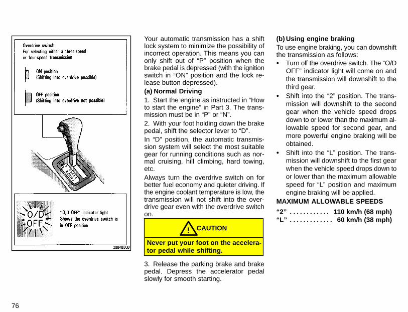
76
Your automatic transmission has a shiftlock system to minimize the possibility ofincorrect operation. This means you canonly shift out of “P” position when thebrake pedal is depressed (with the ignitionswitch in “ON” position and the lock re-lease button depressed).(a) Normal Driving1. Start the engine as instructed in “Howto start the engine” in Part 3. The trans-mission must be in “P” or “N”.2. With your foot holding down the brakepedal, shift the selector lever to “D”.In “D” position, the automatic transmis-sion system will select the most suitablegear for running conditions such as nor-mal cruising, hill climbing, hard towing,etc.Always turn the overdrive switch on forbetter fuel economy and quieter driving. Ifthe engine coolant temperature is low, thetransmission will not shift into the over-drive gear even with the overdrive switchon.
Never put your foot on the accelera-tor pedal while shifting.
CAUTION!
3. Release the parking brake and brakepedal. Depress the accelerator pedalslowly for smooth starting.
(b) Using engine brakingTo use engine braking, you can downshiftthe transmission as follows:� Turn off the overdrive switch. The “O/D
OFF” indicator light will come on andthe transmission will downshift to thethird gear.
� Shift into the “2” position. The trans-mission will downshift to the secondgear when the vehicle speed dropsdown to or lower than the maximum al-lowable speed for second gear, andmore powerful engine braking will beobtained.
� Shift into the “L” position. The trans-mission will downshift to the first gearwhen the vehicle speed drops down toor lower than the maximum allowablespeed for “L” position and maximumengine braking will be applied.
MAXIMUM ALLOWABLE SPEEDS
“2” 110 km/h (68 mph). . . . . . . . . . . . “L” 60 km/h (38 mph). . . . . . . . . . . . .
77
Be careful when downshifting on aslippery surface. Abrupt shiftingcould cause the vehicle to spin orskid.
CAUTION!
NOTICE
�Be careful not to overrev the en-gine. Watch the tachometer to keepengine rpm from going into the redzone. The maximum allowablespeed (approximate) for each posi-tion is given above for your refer-ence.
�Do not continue hill climbing for along time in the “2” or “L” position.This may cause severe automatictrasmission damage from over-heating. To prevent such damage,use “D” position for hill climbingor hard towing.
(c) Backing up1. Bring the vehicle to a complete stop.2. With the brake pedal held down withyour foot, shift the selector lever to the “R”position.
NOTICE
Never shift into reverse while thevehicle is moving.
(d) Parking1. Bring the vehicle to a complete stop.2. Pull the parking brake lever up fully tosecurely apply the parking brake.3. With the brake pedal pressed down,shift the selector lever to the “P” position.
While the vehicle is moving neverattempt to move the selector leverinto “P” position under any circum-stances. Serious mechanical da-mage and loss of vehicle controlmay result.
CAUTION!
(e) Good driving practice� If the transmission is repeatedly up-
shifted and downshifted between thirdgear and overdrive when climbing agentle slope, the overdrive switchshould be turned off. Be sure to turnthe switch on immediately afterward.
� When towing a trailer, in order to main-tain engine braking efficiency, do notuse overdrive.
Always keep your foot on the brakepedal while stopped with the enginerunning. This prevents the vehiclefrom creeping.
CAUTION!
NOTICE
Do not hold the vehicle on anupgrade with the accelerator pedal.It can cause the transmission tooverheat. Always use the brakepedal or parking brake.
(f) If you cannot shift the selector leverout of “P” position
If you cannot shift the selector lever from“P” position even though the brake pedalis depressed, use the shift lock overridebutton. For instructions, see “If you can-not shift automatic transmission slelectorlever” in Part 4.
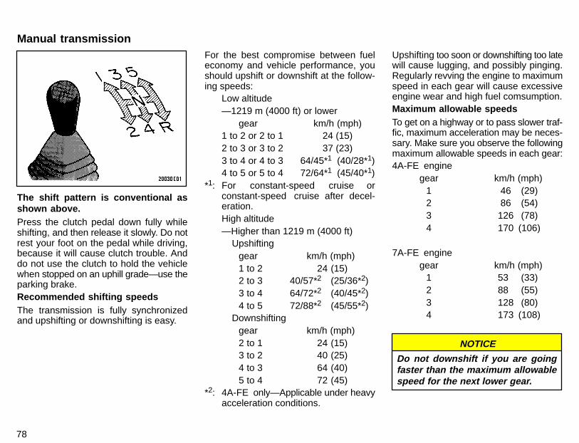
78
The shift pattern is conventional asshown above.Press the clutch pedal down fully whileshifting, and then release it slowly. Do notrest your foot on the pedal while driving,because it will cause clutch trouble. Anddo not use the clutch to hold the vehiclewhen stopped on an uphill grade—use theparking brake.Recommended shifting speedsThe transmission is fully synchronizedand upshifting or downshifting is easy.
For the best compromise between fueleconomy and vehicle performance, youshould upshift or downshift at the follow-ing speeds:
Low altitude—1219 m (4000 ft) or lower
gear km/h (mph)1 to 2 or 2 to 1 24 (15)2 to 3 or 3 to 2 37 (23)3 to 4 or 4 to 3 64/45*1 (40/28*1)4 to 5 or 5 to 4 72/64*1 (45/40*1)
*1: For constant-speed cruise orconstant-speed cruise after decel-eration.High altitude—Higher than 1219 m (4000 ft)
Upshiftinggear km/h (mph)1 to 2 24 (15)2 to 3 40/57*2 (25/36*2)3 to 4 64/72*2 (40/45*2)4 to 5 72/88*2 (45/55*2)
Downshiftinggear km/h (mph)2 to 1 24 (15)3 to 2 40 (25)4 to 3 64 (40)5 to 4 72 (45)
*2: 4A-FE only—Applicable under heavyacceleration conditions.
Upshifting too soon or downshifting too latewill cause lugging, and possibly pinging.Regularly revving the engine to maximumspeed in each gear will cause excessiveengine wear and high fuel comsumption.Maximum allowable speedsTo get on a highway or to pass slower traf-fic, maximum acceleration may be neces-sary. Make sure you observe the followingmaximum allowable speeds in each gear:4A-FE engine
gear km/h (mph)1 46 (29)2 86 (54)3 126 (78)4 170 (106)
7A-FE enginegear km/h (mph)
1 53 (33)2 88 (55)3 128 (80)4 173 (108)
NOTICE
Do not downshift if you are goingfaster than the maximum allowablespeed for the next lower gear.
Manual transmission
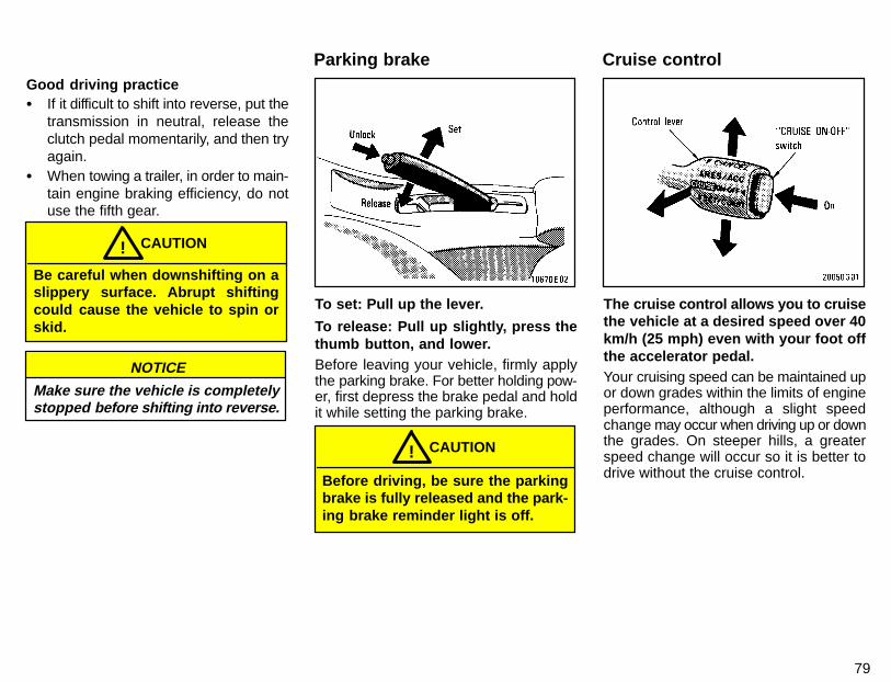
79
Good driving practice� If it difficult to shift into reverse, put the
transmission in neutral, release theclutch pedal momentarily, and then tryagain.
� When towing a trailer, in order to main-tain engine braking efficiency, do notuse the fifth gear.
Be careful when downshifting on aslippery surface. Abrupt shiftingcould cause the vehicle to spin orskid.
CAUTION!
NOTICE
Make sure the vehicle is completelystopped before shifting into reverse.
To set: Pull up the lever.
To release: Pull up slightly, press thethumb button, and lower.Before leaving your vehicle, firmly applythe parking brake. For better holding pow-er, first depress the brake pedal and holdit while setting the parking brake.
Before driving, be sure the parkingbrake is fully released and the park-ing brake reminder light is off.
CAUTION!
The cruise control allows you to cruisethe vehicle at a desired speed over 40km/h (25 mph) even with your foot offthe accelerator pedal.Your cruising speed can be maintained upor down grades within the limits of engineperformance, although a slight speedchange may occur when driving up or downthe grades. On steeper hills, a greaterspeed change will occur so it is better todrive without the cruise control.
Parking brake Cruise control
80
� To help maintain maximum controlof your vehicle, do not use thecruise control when driving inheavy or varying traffic, or on slip-pery (rainy, icy or snow-covered)or winding roads.
� Avoid vehicle speed increaseswhen driving downhill. If the ve-hicle speed is too fast in relation tothe cruise control set speed, can-cel the cruise control then down-shift the transmission to use en-gine braking to slow down.
CAUTION!
TURNING ON THE SYSTEMTo operate the cruise control, push the“CRUISE ON-OFF” switch. This turns thesystem on. The indicator light in the instru-ment panel shows that you can now setthe vehicle at a desired cruising speed.Another push will turn the system com-pletely off.
To avoid accidental cruise controlengagement, keep the “CRUISE ON-OFF” switch off when not using thecruise control.
CAUTION!
SETTING AT A DESIRED SPEEDOn vehicles with automatic transmission,the transmission must be in “D” beforeyou set the cruise control speed.Bring your vehicle to the desired speed,press the “SET/COAST” direction and re-lease it. This sets the vehicle at thatspeed. Now you may take your foot off theaccelerator pedal. If you need accelera-tion—for example, when passing—de-press the accelerator pedal enough forthe vehicle to exceed the set speed.When you release it, the vehicle will returnto the speed set prior to the acceleration.
For manual transmission:
While driving with the cruise controlon, do not shift to neutral withoutdepressing the clutch pedal, as thismay cause engine racing or overrev-ing.
CAUTION!
CANCELLING THE PRESET SPEEDYou can cancel the preset speed by:a. Pulling the control lever in the “CAN-CEL” direction and releasing it.b. Depressing the brake pedal.c. Depressing the clutch pedal (manualtransmission).
If the vehicle speed falls below about 40km/h (25 mph), the preset speed will auto-matically cancel out.If the vehicle speed drops 16 km/h (10mph) below the preset speed, the presetspeed will also automatically cancel out.If the preset speed automatically cancelsout other than for the above cases, haveyour vehicle checked by your Toyota deal-er at the earliest opportunity.RESETTING AT A FASTER SPEEDPress the control lever upward in the“RES/ACC” direction and hold it. Releasethe lever when the desired speed is at-tained. While the lever is held upward, thevehicle will gradually gain speed.However, a faster way to reset is to accel-erate the vehicle and then press the leverdownward in the “SET/COAST” direction.RESETTING AT A SLOWER SPEEDPush the control lever downward in the“SET/COAST” direction and hold it. Re-lease the lever when the desired speed isattained. While the lever is held down-ward, the vehicle speed will gradually de-crease.
81
However, a faster way to reset is to de-press the brake pedal and then press thecontrol lever downward in the “SET/COAST” direction.RESUMING THE PRESET SPEEDIf the preset speed is cancelled by pullingthe control lever or by depressing thebrake pedal or clutch pedal, pushing thelever up in the “RES/ACC” direction willrestore the speed set prior to cancellation.However, once the vehicle speed falls be-low about 40 km/h (25 mph), the presetspeed will not be resumed.CRUISE CONTROL FAILURE WARNINGIf the “CRUISE” indicator light in the in-strument cluster flashes when using thecruise control, there is some trouble in thecruise control system. Contact your Toyo-ta dealer and have your vehicle inspected.

82
Part 1 Car audio system operating tips
83
OPERATION OFINSTRUMENTSAND CONTROLS—
Chapter 1-7Car audio systemand Air conditioningsystem
� Car audio system operating tips� AM-FM radio with electronic
tuner� AM-FM radio with electronic
tuner and cassette tape player� Air conditioning controls� Heater controls� Side vents
You can listen to the car audio systemwhen the ignition key is at “ON” or“ACC”. However, if the engine is notrunning, the key must be in the “ACC”position.
ILLUMINATION CONTROL LOGICOn some audio-units, when the instru-ment panel lights are on, the letters on op-erable buttons of the mode in current uselight up together with the mode selectionand eject buttons.RADIO
FM reception tipsMost of us are not aware that a vehicle isnot an ideal place to listen to a radio. Be-cause it moves, reception conditionschange continuously. Buildings, terrain,signal distance and noise from other ve-hicles are all working against good recep-tion. Some FM reception conditions mayappear to be problems even though theyare normal.The following characteristics are normalfor a given reception area, and they do notindicate any problem with the radio itself.� Fading and Drifting : On the average,
the broadcast range of FM stations islimited to about 40 km (25 miles), ex-cept for some high power stations.
If a vehicle is moving away from thedesired station’s transmitter, the signalwill tend to fade and/or drift. This phe-nomenon is more noticeable with FMthan with AM, and is accompanied bydistortion.Fading and drifting can be minimizedto a certain degree by fine tuning, oryou should tune in to a stronger signal.
� Static and Fluttering : When the line-of-sight path between a transmitterand vehicle is blocked by large build-ings or the like, static or fluttering mayoccur because of the characteristic ofFM. In a similar effect, a flutteringnoise is sometimes heard when driv-ing along a tree-lined road.This static and fluttering can be re-duced by adjusting the tone control forgreater bass response until the distur-bance has passed.
� Multipath : Because of the reflectioncharacteristics of FM, direct and re-flected signals may reach the antennaat the same time (a phenomenoncalled multipath reception) and canceleach other out. As a vehicle movesthrough these electronic dead spots,the listener may hear a momentaryflutter or lose reception.
84
� Station swapping : When two FM sta-tions are close to each other, and anelectronic dead spot, such as iscaused by static or multipath recep-tion, interrupts the original signal,sometimes the stronger second signalis picked up automatically until theoriginal one returns. This swappingcan also occur as you drive away fromthe selected station and approachanother station with a stronger signal.
On models with a power antenna, the an-tenna automatically extends to its fullheight when the radio and ignition areturned on.To lower the power antenna, turn off theaudio system by pushing “PWR.VOL”, orturn the ignition key to “LOCK”.On some models, the power antenna au-tomatically retracts when the radio modeis switched off to turn on the cassette tapeplayer.Before extending the power antenna,confirm that no one is close enough to getinjured by it.
To prevent damage to the antenna,make sure it is retracted beforedriving your vehicle through anautomatic car wash.
NOTICE
CASSETTE TAPE PLAYER
Use only undamaged cassette tapes ofgood quality. Avoid using tapes with atotal playing time longer than 90 min-utes.Using damaged tapes will cause troublewith the tape player. Longer tapes are notrecommended because of their thinness.Before inserting a cassette, make surethe tape is not slack and that the labelis firmly stuck on the shell.Wind the tape firmly by turning the hubwith a pencil or the like.Be careful not to touch the exposed tapesurface.When not in use, take the cassette outof the player, put it back into its caseand store it away from dust, magnetsand direct sunlight.Leaving cassettes on the dashboard inthe sun could damage your tapes.Keep the playback head, capstan andpinch roller clean.Remove tape coating residue accumu-lated on the head, capstan and pinch roll-er once or twice a month. A cleaning tapeis available on the market.
Do not oil any part of the player anddo not insert anything other thancassette tapes into the slot, or thetape player may be damaged.
NOTICE
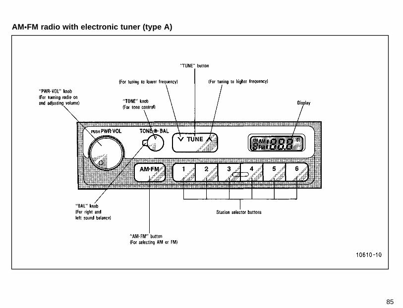
85
AM�FM radio with electronic tuner (type A)
86
(a) Listening to the radio1. Push the “PWR�VOL” knob to turn theradio on.2. Turn the “PWR�VOL” knob to adjustthe volume.3. Tune in the desired station. (See “(b)Selecting a station” and “(c) Presetting astation”.)The radio will change automatically to ste-reo reception when an FM stereo broad-cast is being received. At the same time,“ST” will appear on the display. When thereceiving signal gets weak, the channelseparation will automatically be reducedfor the lowest noise. If the signal becomesextremely weak, the radio will switch overto monaural reception.4. Adjust the tone and sound balance.(See “(d) Adjusting the tone” and “(e) Ad-justing the sound balance”.)5. To turn the radio off, push the“PWR�VOL” knob once again.(b) Selecting a station1. Push the “AM�FM” button to select ei-ther an AM or FM broadcast. “AM” or “FM”will appear on the display.2. Tune in the desired station using oneof the following methods. The frequencywill appear on the display.
Preset tuning: Use for tuning-in to a de-sired preset station.Push the station selector button whichhas been preset to the desired station.The radio will tune in to the station and thebutton number will appear on the display.(See “(c) Presetting a station”.)Seek tuning: Use for automatic stationsearch and stop.Push either side of the “TUNE” button andhold it until a beep is heard. The radio willbegin seeking up or down for a station ofthe nearest frequency and will stop on re-ception. Each time you push the button,stations will be sought out one after anoth-er.Manual tuningPush either side of the “TUNE” button forless than 0.5 second. Each time you pushthe button, the radio will step up or downto another frequency where stations couldexist.(c) Presetting a station1. Tune in the desired station. (See “(b)Selecting a station”.)2. Push one of the station selector but-tons and hold it until a beep is heard. Thissets the station to the button and the but-ton number will appear on the display.
Each button can store one AM station andone FM station. To change the preset sta-tion to a different one, follow the same pro-cedure.The preset station will be cancelled whenthe power source is severed (battery dis-connected, burnt fuse, etc.).(d) Adjusting the toneTurn the “TONE” knob.(e) Adjusting the sound balanceTurn the “BAL” knob.

87
AM�FM radio with electronic tuner (type B)
88
(a) Listening to the radio1. Push the “PWR�VOL” knob to turn theradio on.2. Turn the “PWR�VOL” knob to adjustthe volume.3. Tune in the desired station. (See “(b)Selecting a station” and “(c) Presetting astation”.)The radio will change automatically to ste-reo reception when an FM stereo broad-cast is being received. At the same time,“ST” will appear on the display. When thereceiving signal gets weak, the channelseparation will automatically be reducedfor the lowest noise. If the signal becomesextremely weak, the radio will switch overto monaural reception.4. Adjust the tone and sound balance.(See “(d) Adjusting the tone” and“(e) Adjusting the sound balance”.)5. To turn the radio off, push the“PWR�VOL” knob once again.(b) Selecting a station1. Push the “AM�FM” button to select ei-ther an AM or FM broadcast. “AM” or “FM”will appear on the display.2. Tune in the desired station using oneof the following methods. The frequencywill appear on the display.
Preset tuning: Use for tuning-in to a de-sired preset station.Push the station selector button whichhas been preset to the desired station.The radio will tune in to the station and thebutton number will appear on the display.(See “(c) Presetting a station”.)Seek tuning: Use for automatic stationsearch and stop.Push either side of the “TUNE” button andhold it until a beep is heard. The radio willbegin seeking up or down for a station ofthe nearest frequency and will stop on re-ception. Each time you push the button, sta-tions will be sought out one after another.Scan tuning: Use for station-to-stationscanning.Push the “SCAN” button. With “SCAN” onthe display, the radio will automaticallyseek out a station of a higher frequency,hold it for 5 seconds and scan to the next.To continue listening to the broadcast ofyour choice, simply push the “SCAN” but-ton once again.Manual tuningPush either side of the “TUNE” button forless than 0.5 second. Each time you pushthe button, the radio will step up or downto another frequency where stations couldexist.
(c) Presetting a station1. Tune in the desired station. (See “(b)Selecting a station”.)2. Push one of the station selector but-tons and hold it until a beep is heard. Thissets the station to the button and thebutton number will appear on the display.Each button can store one AM station andone FM station. To change the preset sta-tion to a different one, follow the same pro-cedure.The preset station will be cancelled whenthe power source is severed (battery dis-connected, burnt fuse, etc.).(d) Adjusting the toneTo adjust a low-pitched tone, push the“BASS TREB” knob (if pushed in) andturn it.To adjust a high-pitched tone, push the“BASS TREB” knob (if pushed in), pull itfully out and turn it.(e) Adjusting the sound balanceTo balance the sound between the rightand left speakers, push the “BAL FADE”knob (if pushed in) and turn it.To balance the sound between the front andrear speakers, push the “BAL FADE” knob(if pushed in), pull it fully out and turn it.
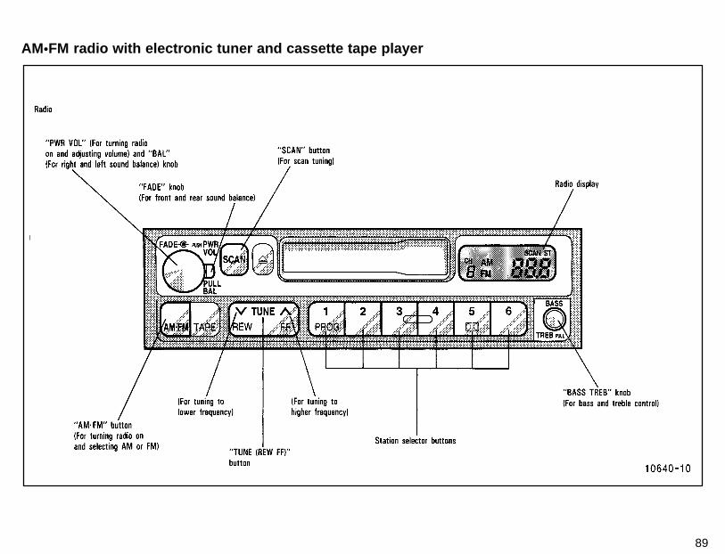
89
AM�FM radio with electronic tuner and cassette tape player
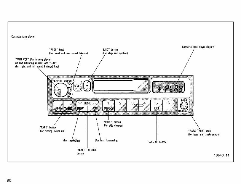
90
91
(a) Listening to the radio1. Push the “AM�FM” button to turn theradio on and select either an AM or FMbroadcast.“AM” or “FM” will appear on the display.The radio can also be turned on by push-ing the “PWR VOL” knob if the radio wason when the system was turned off.2. Turn the “PWR VOL” knob to adjust thevolume.3. Tune in the desired station. (See “(b)Selecting a station” and “(c) Presetting astation”.)The radio will change automatically to ste-reo reception when an FM stereo broad-cast is being received. At the same time,“ST” will appear on the display. When thereceiving signal gets weak, the channelseparation will automatically be reducedfor the lowest noise. If the signal becomesextremely weak, the radio will switch overto monaural reception.4. Adjust the tone and sound balance.(See “(d) Adjusting the tone” and “(e) Ad-justing the sound balance”.)5. To turn the radio off, push the “PWRVOL” knob.
(b) Selecting a stationTune in the desired station using one ofthe following methods. The frequency willappear on the display.Preset tuning: Use for tuning-in to a de-sired preset station. (See “(c) Presettinga station”.)Push the station selector button whichhas been preset to the desired station.The radio will tune in to the station and thebutton number will appear on the display.Seek tuning: Use for automatic stationsearch and stop.Push the “TUNE (REW FF)” button on ei-ther side and hold it until a beep is heard.The radio will begin seeking up or down fora station of the nearest frequency and willstop on reception. Each time you push thebutton, stations will be sought out one af-ter another.Scan tuning: Use for station-to-stationscanning.Scanning for all frequencies—Push the“SCAN” button and hold it until a beep isheard. With “SCAN” on the display, the ra-dio will automatically seek out a station ofa higher frequency, hold it for 5 secondsand scan to the next. To continue listeningto the broadcast of your choice, simplypush the “SCAN” button once again.
If the radio scans over all frequencieswithout stop because the signals are tooweak or just because you leave it going,the radio will begin scanning again withsensitivity boosted for searching out weakstations.Scanning for preset stations—Push the“SCAN” button within 2 seconds. With“SCAN” on the display, the radio will auto-matically seek out a preset station, hold itfor 5 seconds and scan to the next. Tocontinue listening to the station of yourchoice, simply push the “SCAN” buttononce again.Manual tuningPush the “TUNE (REW FF)” button on ei-ther side for less than 0.5 second. Eachtime you push the button, the radio willstep up or down to another frequencywhere stations could exist.(c) Presetting a station1. Tune in the desired station. (See “(b)Selecting a station”.)2. Push one of the station selector but-tons and hold it until a beep is heard. Thissets the station to the button and the but-ton number will appear on the display.Each button can store one AM station andone FM station. To change the preset sta-tion to a different one, follow the same pro-cedure.
92
The preset station will be cancelled whenthe power source is severed (battery dis-connected, burnt fuse, etc.).(d) Adjusting the toneTo adjust a low-pitched tone, push the“BASS TREB” knob (if pushed in) and turnit.To adjust a high-pitched tone, push the“BASS TREB” knob (if pushed in), pull itfully out and turn it.(e) Adjusting the sound balanceTo balance the sound between the rightand left speakers, pull the “BAL” knob andturn it.To balance the sound between the frontand rear speakers, turn the “FADE” knob.(f) Listening to the cassette tape1. Put the cassette into the slot, with thetape side to the right and lightly push it in.The tape player will grab the cassette andslide it into place to play it. If the radio ison when inserting the cassette, the radiowill automatically turn off.If the cassette is already in the slot, pushthe “TAPE” button.At this time, “PLAY” will appear on the dis-play.
The tape player can also be turned on bypushing the “PWR VOL” knob if the tapeplayer was playing when the system wasturned off by pushing the knob.2. If using a tape recorded with Dolby�
NR*, push the button marked with thedouble-D symbol. The display will indi-cate that the Dolby noise reduction sys-tem is on.The Dolby NR mode reduces tape noiseby about 10 dB. For best sound reproduc-tion, play your tapes with the Dolby� NR*on or off according to the mode used forrecording the tape.To play a tape recorded without Dolby�
NR*, push the button again to turn off theDolby� NR*.*: Dolby noise reduction manufactured under license from Dolby
Laboratories Licensing Corporation. “DOLBY” and the double-Dsymbol are trademarks of Dolby Laboratories Licensing Corpo-ration.
3. Turn the “PWR VOL” knob to adjust thevolume.4. Select your program. (See “(g) Select-ing a program”.)5. Adjust the tone and sound balance.(See “(d) Adjusting the tone” and “(e) Ad-justing the sound balance”.)
6. To turn the player off, push the “PWRVOL” knob.7. To eject the cassette, push the EJECTbutton. As this is done, the player will turnoff. If the radio was on when the cassettetape was inserted, it will automatically turnon again.You can eject the cassette only once afterthe system is turned off.(g) Selecting a program1. Push the “PROG” button to select aside to play. The tape operation indicatordisplay shows you which side is beingplayed.The player will automatically reverse di-rections at the end of the tape to play theother side.2. Push the “REW FF (TUNE)” button oneither side to fast forward or rewind thetape. At this time, “FF” or “REW” will ap-pear on the display. To stop the tape whileit is fast forwarding, push “FF” or “TAPE”;to stop the tape while it is rewinding, push“REW” or “TAPE”. The tape will immedi-ately begin to play.
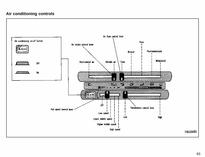
93
Air conditioning controls
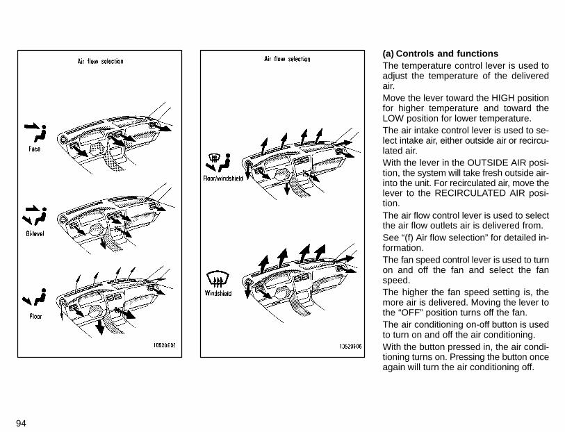
94
(a) Controls and functionsThe temperature control lever is used toadjust the temperature of the deliveredair.Move the lever toward the HIGH positionfor higher temperature and toward theLOW position for lower temperature.The air intake control lever is used to se-lect intake air, either outside air or recircu-lated air.With the lever in the OUTSIDE AIR posi-tion, the system will take fresh outside air-into the unit. For recirculated air, move thelever to the RECIRCULATED AIR posi-tion.The air flow control lever is used to selectthe air flow outlets air is delivered from.See “(f) Air flow selection” for detailed in-formation.The fan speed control lever is used to turnon and off the fan and select the fanspeed.The higher the fan speed setting is, themore air is delivered. Moving the lever tothe “OFF” position turns off the fan.The air conditioning on-off button is usedto turn on and off the air conditioning.With the button pressed in, the air condi-tioning turns on. Pressing the button onceagain will turn the air conditioning off.
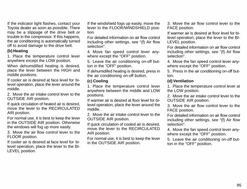
95
If the indicator light flashes, contact yourToyota dealer as soon as possible. Theremay be a slippage of the drive belt ortrouble in the compressor. If this happens,the air conditioning is automatically turnedoff to avoid damage to the drive belt.(b) Heating1. Place the temperature control leveranywhere except the LOW position.When dehumidified heating is desired,place the lever between the HIGH andmiddle positions.If cooler air is desired at face level for bi-level operation, place the lever around themiddle.2. Move the air intake control lever to theOUTSIDE AIR position.If quick circulation of heated air is desired,move the lever to the RECIRCULATEDAIR position.For normal use, it is best to keep the leverin the OUTSIDE AIR position. Otherwisethe windows will fog up more easily.3. Move the air flow control lever to theFLOOR position.If cooler air is desired at face level for bi-level operation, place the lever to the BI-LEVEL position.
If the windshield fogs up easily, move thelever to the FLOOR/WINDSHIELD posi-tion.For detailed information on air flow controlincluding other settings, see “(f) Air flowselection”.4. Move fan speed control lever any-where except the “OFF” position.5. Leave the air conditioning on-off but-ton in the ”OFF” position.If dehumidifed heating is desired, press inthe air conditioning on-off button.(c) Cooling1. Place the temperature control leveranywhere between the middle and LOWpositions.If warmer air is desired at floor level for bi-level operation, place the lever around themiddle.2. Move the air intake control lever to theOUTSIDE AIR position.If quick circulation of cooled air is desired,move the lever to the RECIRCULATEDAIR position.For normal use, it is best to keep the leverin the OUTSIDE AIR position.
3. Move the air flow control lever to theFACE position.If warmer air is desired at floor level for bi-level operation, place the lever to the BI-LEVEL position.For detailed information on air flow controlincluding other settings, see “(f) Air flowselection”.4. Move the fan speed control lever any-where except the “OFF” position.5. Press in the air conditioning on-off but-ton.(d) Ventilation1. Place the temperature control lever atthe LOW position.2. Move the air intake control lever to theOUTSIDE AIR position.3. Move the air flow control lever to theFACE position.For detailed information on air flow controlincluding other settings, see “(f) Air flowselection”.4. Move the fan speed control lever any-where except the “OFF” position.5. Leave the air conditioning on-off but-ton in the “OFF” position.
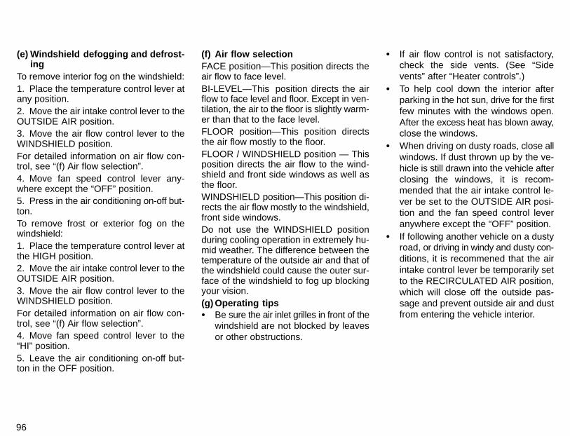
96
(e) Windshield defogging and defrost-ing
To remove interior fog on the windshield:1. Place the temperature control lever atany position.2. Move the air intake control lever to theOUTSIDE AIR position.3. Move the air flow control lever to theWINDSHIELD position.For detailed information on air flow con-trol, see “(f) Air flow selection”.4. Move fan speed control lever any-where except the “OFF” position.5. Press in the air conditioning on-off but-ton.To remove frost or exterior fog on thewindshield:1. Place the temperature control lever atthe HIGH position.2. Move the air intake control lever to theOUTSIDE AIR position.3. Move the air flow control lever to theWINDSHIELD position.For detailed information on air flow con-trol, see “(f) Air flow selection”.4. Move fan speed control lever to the“HI” position.5. Leave the air conditioning on-off but-ton in the OFF position.
(f) Air flow selectionFACE position—This position directs theair flow to face level.BI-LEVEL—This position directs the airflow to face level and floor. Except in ven-tilation, the air to the floor is slightly warm-er than that to the face level.FLOOR position—This position directsthe air flow mostly to the floor.FLOOR / WINDSHIELD position — Thisposition directs the air flow to the wind-shield and front side windows as well asthe floor.WINDSHIELD position—This position di-rects the air flow mostly to the windshield,front side windows.Do not use the WINDSHIELD positionduring cooling operation in extremely hu-mid weather. The difference between thetemperature of the outside air and that ofthe windshield could cause the outer sur-face of the windshield to fog up blockingyour vision.(g) Operating tips� Be sure the air inlet grilles in front of the
windshield are not blocked by leavesor other obstructions.
� If air flow control is not satisfactory,check the side vents. (See “Sidevents” after “Heater controls”.)
� To help cool down the interior afterparking in the hot sun, drive for the firstfew minutes with the windows open.After the excess heat has blown away,close the windows.
� When driving on dusty roads, close allwindows. If dust thrown up by the ve-hicle is still drawn into the vehicle afterclosing the windows, it is recom-mended that the air intake control le-ver be set to the OUTSIDE AIR posi-tion and the fan speed control leveranywhere except the “OFF” position.
� If following another vehicle on a dustyroad, or driving in windy and dusty con-ditions, it is recommened that the airintake control lever be temporarily setto the RECIRCULATED AIR position,which will close off the outside pas-sage and prevent outside air and dustfrom entering the vehicle interior.
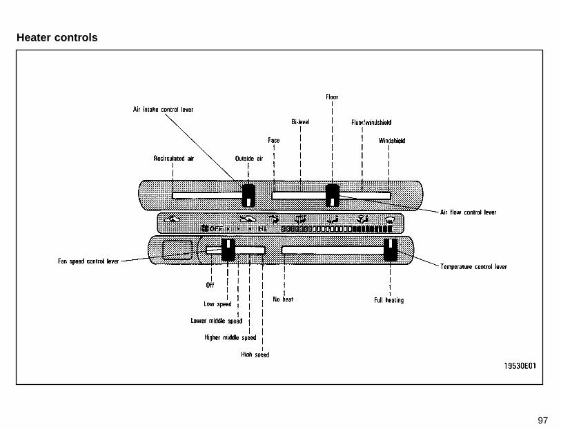
97
Heater controls
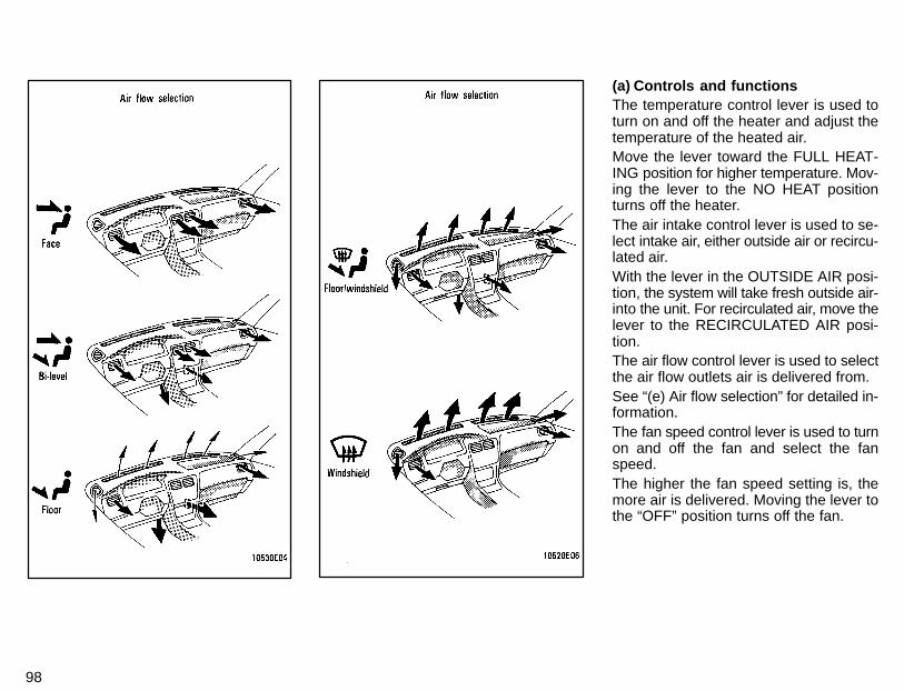
98
(a) Controls and functionsThe temperature control lever is used toturn on and off the heater and adjust thetemperature of the heated air.Move the lever toward the FULL HEAT-ING position for higher temperature. Mov-ing the lever to the NO HEAT positionturns off the heater.The air intake control lever is used to se-lect intake air, either outside air or recircu-lated air.With the lever in the OUTSIDE AIR posi-tion, the system will take fresh outside air-into the unit. For recirculated air, move thelever to the RECIRCULATED AIR posi-tion.The air flow control lever is used to selectthe air flow outlets air is delivered from.See “(e) Air flow selection” for detailed in-formation.The fan speed control lever is used to turnon and off the fan and select the fanspeed.The higher the fan speed setting is, themore air is delivered. Moving the lever tothe “OFF” position turns off the fan.
99
(b) Heating1. Place the temperature control leveranywhere except the NO HEAT position.If cooler air is desired at face level for bi-level operation, place the lever around themiddle.2. Move the air intake control lever to theOUTSIDE AIR position.If quick circulation of heated air is desired,move the lever to the RECIRCULATEDAIR position.For normal use, it is best to keep the leverin the OUTSIDE AIR position. Otherwisethe windows will fog up more easily.3. Move the air flow control lever to theFLOOR position.If cooler air is desired at face level for bi-level operation, move the lever to the BI-LEVEL position.If the windshield fogs up easily, move thelever to the FLOOR/WINDSHIELD posi-tion.For detailed information on air flow controlincluding other settings, see “(e) Air flowselection”.4. Move fan speed control lever any-where except the “OFF” position.
(c) Ventilation1. Place the temperature control lever atthe NO HEAT position.2. Move the air intake control lever to theOUTSIDE AIR position.3. Move the air flow control lever to theFACE position.For detailed information on air flow controlincluding other settings, see “(e) Air flowselection”.4. Move fan speed control lever any-where except the “OFF” position.(d) Windshield defogging and defrost-
ing1. Place the temperature control lever atFULL HEATING position.2. Move the air intake control lever to theOUTSIDE AIR position.3. Move the air flow control lever to theWINDSHIELD position.For detailed information on air flow con-trol, see “(e) Air flow selection”.4. Move fan speed control lever to the“HI” position.(e) Air flow selectionFACE position—This position directs theair flow to face level.
BI-LEVEL position—This position directsthe air flow to face level and floor. Exceptin ventilation, the air to the floor is slightlywarmer than that to face level.FLOOR position—This position directsthe air flow mostly to the floor.FLOOR / WINDSHIELD position — Thisposition directs the air flow to the wind-shield and front side windows as well asthe floor.WINDSHIELD position—This position di-rects the air flow mostly to the windshield,front side windows.(f) Operating tips� Be sure the air inlet grilles in front of the
windshield are not blocked by leavesor other obstructions.
� If air flow control is not satisfactory, checkthe side vents. (See “Side vents”.)
� When driving on dusty roads, close allwindows. If dust thrown up by the ve-hicle is still drawn into the vehicle afterclosing the windows, it is recom-mended that the air intake control le-ver be set to the OUTSIDE AIR posi-tion and the fan speed control leveranywhere except the “OFF” position.
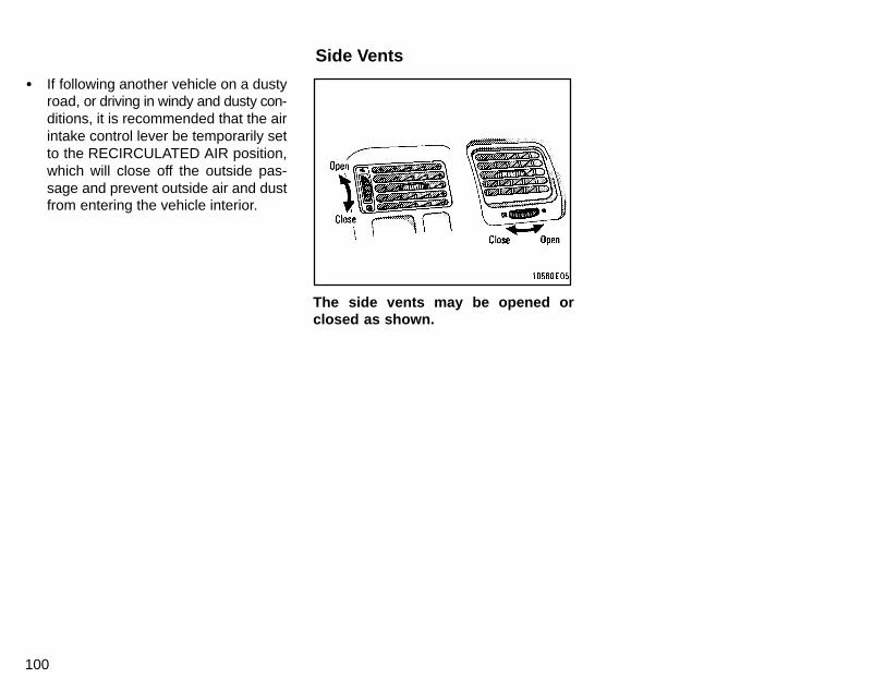
100
� If following another vehicle on a dustyroad, or driving in windy and dusty con-ditions, it is recommended that the airintake control lever be temporarily setto the RECIRCULATED AIR position,which will close off the outside pas-sage and prevent outside air and dustfrom entering the vehicle interior.
The side vents may be opened orclosed as shown.
Side Vents
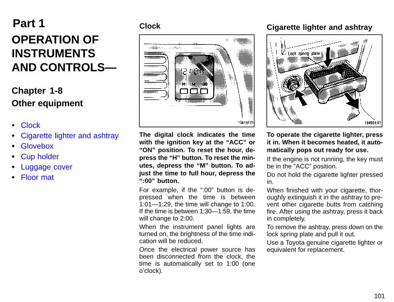
Part 1 Clock Cigarette lighter and ashtray
101
OPERATION OFINSTRUMENTSAND CONTROLS—
Chapter 1-8Other equipment
� Clock� Cigarette lighter and ashtray� Glovebox� Cup holder� Luggage cover� Floor mat
The digital clock indicates the timewith the ignition key at the “ACC” or“ON” position. To reset the hour, de-press the “H” button. To reset the min-utes, depress the “M” button. To ad-just the time to full hour, depress the“:00” button.For example, if the “:00” button is de-pressed when the time is between1:01—1:29, the time will change to 1:00.If the time is between 1:30—1:59, the timewill change to 2:00.When the instrument panel lights areturned on, the brightness of the time indi-cation will be reduced.Once the electrical power source hasbeen disconnected from the clock, thetime is automatically set to 1:00 (oneo’clock).
To operate the cigarette lighter, pressit in. When it becomes heated, it auto-matically pops out ready for use.If the engine is not running, the key mustbe in the ”ACC” position.Do not hold the cigarette lighter pressedin.When finished with your cigarette, thor-oughly extinguish it in the ashtray to pre-vent other cigarette butts from catchingfire. After using the ashtray, press it backin completely.To remove the ashtray, press down on thelock spring plate and pull it out.Use a Toyota genuine cigarette lighter orequivalent for replacement.
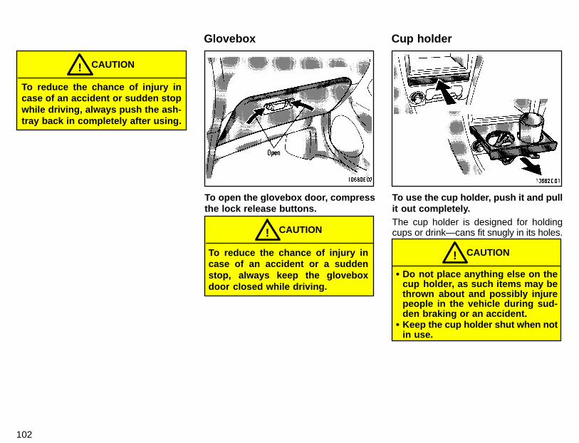
102
To reduce the chance of injury incase of an accident or sudden stopwhile driving, always push the ash-tray back in completely after using.
CAUTION!
To open the glovebox door, compressthe lock release buttons.
To reduce the chance of injury incase of an accident or a suddenstop, always keep the gloveboxdoor closed while driving.
CAUTION!
To use the cup holder, push it and pullit out completely.The cup holder is designed for holdingcups or drink—cans fit snugly in its holes.
� Do not place anything else on thecup holder, as such items may bethrown about and possibly injurepeople in the vehicle during sud-den braking or an accident.
� Keep the cup holder shut when notin use.
CAUTION!
Glovebox Cup holder
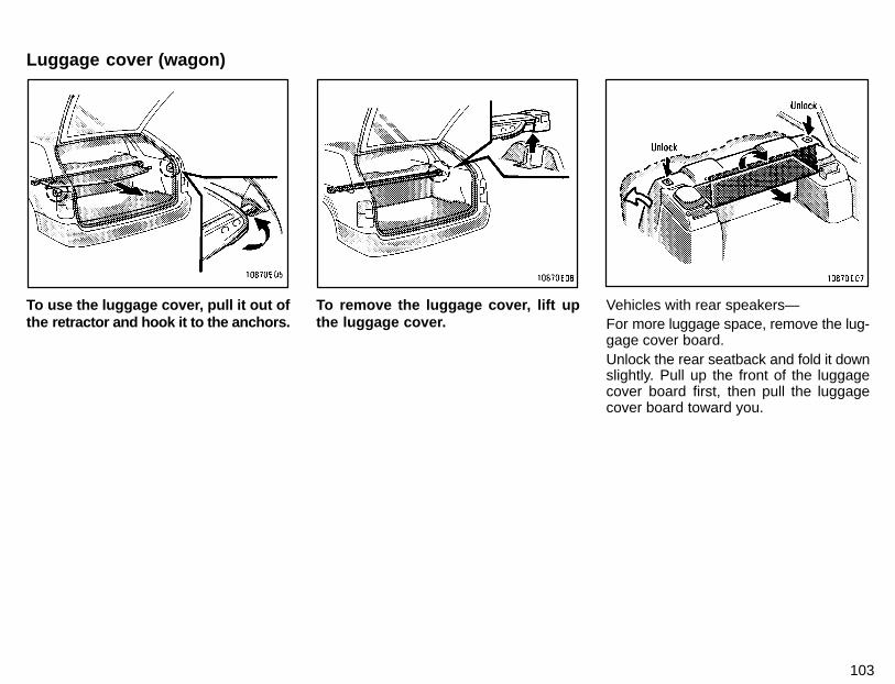
103
To use the luggage cover, pull it out ofthe retractor and hook it to the anchors.
To remove the luggage cover, lift upthe luggage cover.
Vehicles with rear speakers—For more luggage space, remove the lug-gage cover board.Unlock the rear seatback and fold it downslightly. Pull up the front of the luggagecover board first, then pull the luggagecover board toward you.
Luggage cover (wagon)

104
Use a floor mat of the correct size.If the floor mat has a hole, then it is de-signed for use with a locking clip. Fix thefloor mat and locking clip into the hole inthe floor carpet.
Make sure the floor mat is properlyplaced on the floor carpet. If thefloor mat slips and interferes withthe movement of the pedals duringdriving, it may cause an accident.
CAUTION!
Floor mat

Part 2 Break-in period Fuel
105
INFORMATIONBEFORE DRIVINGYOUR TOYOTA
� Break-in period� Fuel� Operation in foreign countries� Three-way catalytic converter� Engine exhaust cautions� Facts about engine oil
consumption� Brake system� Brake pad wear limit indicators� Luggage stowage precautions� Your Toyota’s idenitification� Theft prevention labels� Suspension and chassis� Types of tires
Drive gently and avoid high speeds.Your vehicle does not need an elaboratebreak-in. But following a few simple tipsfor the first 1600 km (1000 miles) can addto the future economy and long life of yourvehicle:� Do not drive over 88 km/h (55 mph).� Avoid overrevving. Maintain engine
speed between 2000 and 4000 rpm.� Avoid full-throttle starts.� Try to avoid hard stops during the first
300 km (200 miles).� Do not drive slowly with the manual
transmission in a high gear.� Do not drive for a long time at any
single speed, either fast or slow.� Do not tow a trailer during the first 800
km (500 miles).
FUEL TYPE
Your new vehicle must use only un-leaded gasoline.To help prevent gas station mixups, yourToyota has a new smaller fuel tank open-ing. The special nozzle on pumps with un-leaded fuel will fit it, but the larger standardnozzle on pumps with leaded gas will not.
Do not use leaded gasoline. Use ofleaded gasoline will cause the three-way catalytic converter to lose its ef-fectiveness and the emission con-trol system to function improperly.Also, this can increase maintenancecosts.
NOTICE
OCTANE NUMBER
Select Research Octane Number 91(Octane Rating 87) or higher.Use of unleaded fuel with an octane num-ber or rating lower than stated above willcause persistent heavy knocking. If se-vere, this will lead to engine damage.
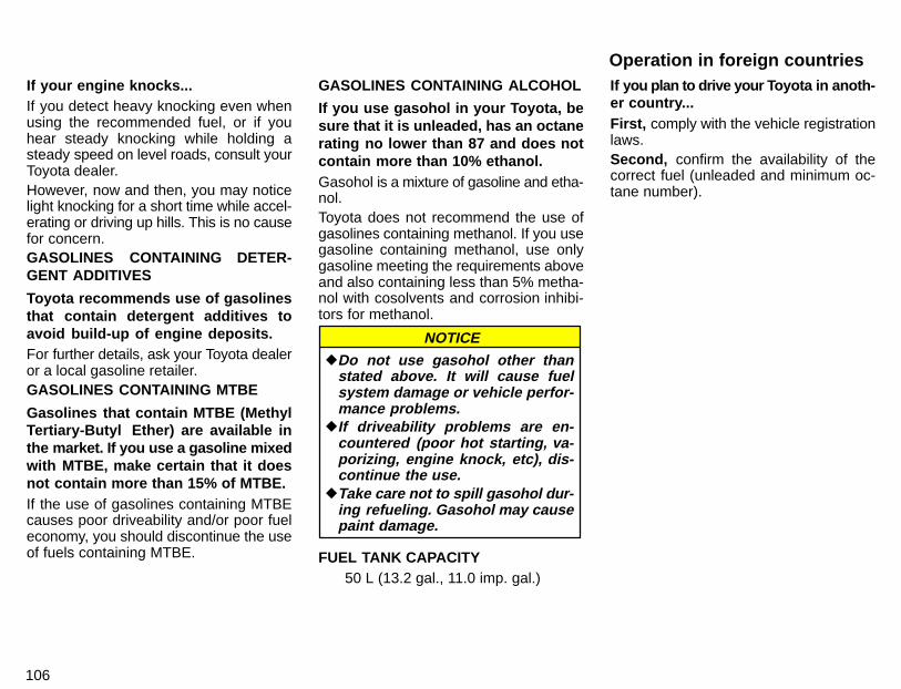
106
If your engine knocks...If you detect heavy knocking even whenusing the recommended fuel, or if youhear steady knocking while holding asteady speed on level roads, consult yourToyota dealer.However, now and then, you may noticelight knocking for a short time while accel-erating or driving up hills. This is no causefor concern.GASOLINES CONTAINING DETER-GENT ADDITIVES
Toyota recommends use of gasolinesthat contain detergent additives toavoid build-up of engine deposits.For further details, ask your Toyota dealeror a local gasoline retailer.GASOLINES CONTAINING MTBE
Gasolines that contain MTBE (MethylTertiary-Butyl Ether) are available inthe market. If you use a gasoline mixedwith MTBE, make certain that it doesnot contain more than 15% of MTBE.If the use of gasolines containing MTBEcauses poor driveability and/or poor fueleconomy, you should discontinue the useof fuels containing MTBE.
GASOLINES CONTAINING ALCOHOL
If you use gasohol in your Toyota, besure that it is unleaded, has an octanerating no lower than 87 and does notcontain more than 10% ethanol.Gasohol is a mixture of gasoline and etha-nol.Toyota does not recommend the use ofgasolines containing methanol. If you usegasoline containing methanol, use onlygasoline meeting the requirements aboveand also containing less than 5% metha-nol with cosolvents and corrosion inhibi-tors for methanol.
�Do not use gasohol other thanstated above. It will cause fuelsystem damage or vehicle perfor-mance problems.
�If driveability problems are en-countered (poor hot starting, va-porizing, engine knock, etc), dis-continue the use.
�Take care not to spill gasohol dur-ing refueling. Gasohol may causepaint damage.
NOTICE
FUEL TANK CAPACITY50 L (13.2 gal., 11.0 imp. gal.)
If you plan to drive your T oyota in anoth-er country...First, comply with the vehicle registrationlaws.Second, confirm the availability of thecorrect fuel (unleaded and minimum oc-tane number).
Operation in foreign countries
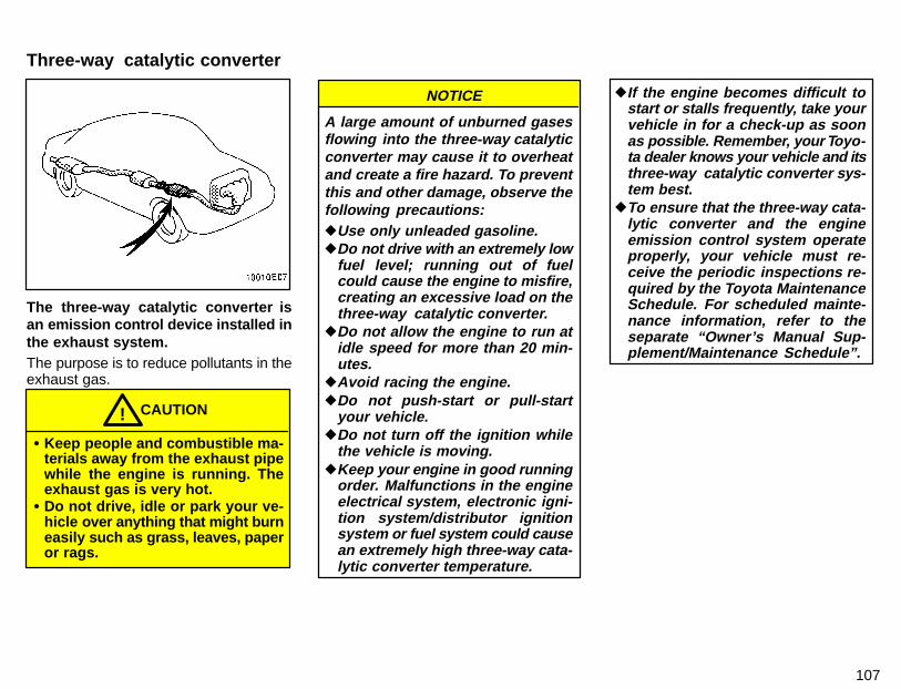
107
The three-way catalytic converter isan emission control device installed inthe exhaust system.The purpose is to reduce pollutants in theexhaust gas.
CAUTION!
� Keep people and combustible ma-terials away from the exhaust pipewhile the engine is running. Theexhaust gas is very hot.
� Do not drive, idle or park your ve-hicle over anything that might burneasily such as grass, leaves, paperor rags.
A large amount of unburned gasesflowing into the three-way catalyticconverter may cause it to overheatand create a fire hazard. To preventthis and other damage, observe thefollowing precautions:�Use only unleaded gasoline.�Do not drive with an extremely low
fuel level; running out of fuelcould cause the engine to misfire,creating an excessive load on thethree-way catalytic converter.
�Do not allow the engine to run atidle speed for more than 20 min-utes.
�Avoid racing the engine.�Do not push-start or pull-start
your vehicle.�Do not turn off the ignition while
the vehicle is moving.�Keep your engine in good running
order. Malfunctions in the engineelectrical system, electronic igni-tion system/distributor ignitionsystem or fuel system could causean extremely high three-way cata-lytic converter temperature.
NOTICE �If the engine becomes difficult tostart or stalls frequently, take yourvehicle in for a check-up as soonas possible. Remember, your Toyo-ta dealer knows your vehicle and itsthree-way catalytic converter sys-tem best.
�To ensure that the three-way cata-lytic converter and the engineemission control system operateproperly, your vehicle must re-ceive the periodic inspections re-quired by the Toyota MaintenanceSchedule. For scheduled mainte-nance information, refer to theseparate “Owner’s Manual Sup-plement/Maintenance Schedule”.
Three-way catalytic converter

108
CAUTION!
� Avoid inhaling the engine exhaust.It contains carbon monoxide,which is a colorless and odorlessgas. It can cause unconsciousnessor even death.
� Make sure the exhaust system hasno holes or loose connections.The system should be checkedfrom time to time. If you hit some-thing, or notice a change in thesound of the exhaust, have the sys-tem checked immediately.
� Do not run the engine in a garageor enclosed area except for thetime needed to drive the vehicle inor out. The exhaust gases cannotescape, making this a particularlydangerous situation.
� Do not remain for a long time in aparked vehicle with the engine run-ning. If it is unavoidable, however,do so only in an unconfined areaand adjust the heating or coolingsystem to force outside air into thevehicle.
� Keep the trunk lid or back doorclosed while driving. An open orunsealed trunk lid or back doormay cause exhaust gases to bedrawn into the vehicle. If you mustdrive with the trunk lid or back dooropen to accommodate a large ob-ject, close the windows, open allthe instrument panel vents andhave the heating or cooling systemdeliver fresh air into the vehicle byturning the fan to high speed withthe air intake control lever set at theOUTSIDE AIR position.
� To allow proper operation of yourvehicle’s ventilation system, keepthe inlet grilles in front of the wind-shield clear of snow, leaves, or oth-er obstructions.
� If you smell exhaust fumes in the ve-hicle, drive with the windows openand the trunk lid or back doorclosed. Have the cause imm ediatelylocated and corrected.
FUNCTIONS OF ENGINE OILEngine oil has the primary functions of lu-bricating and cooling the inside of the en-gine, and plays a major role in maintainingthe engine in proper working order.ENGINE OIL CONSUMPTION
It is normal that an engine should con-sume some engine oil during normalengine operation. The causes of oilconsumption in a normal engine areas follows.� Oil is used to lubricate pistons, piston
rings and cylinders. A thin film of oil isleft on the cylinder wall when a pistonmoves downwards in the cylinder.High negative pressure generatedwhen the vehicle is decelerating suckssome of this oil into the combustionchamber. This oil as well as some partof the oil film left on the cylinder wall isburned by the high temperature com-bustion gases during the combustionprocess.
� Oil is also used to lubricate the stemsof the intake valves. Some of this oil issucked into the combustion chambertogether with the intake air and isburned along with the fuel. High tem-perature exhaust gases also burn theoil used to lubricate the exhaust valvestems.
Facts about engine oilconsumptionEngine exhaust cautions
109
The amount of engine oil consumeddepends on the viscosity of the oil, thequality of the oil and the conditionsthe vehicle is driven under.More oil is consumed by high-speed driv-ing and frequent acceleration and decel-eration.A new engine consumes more oil, sinceits pistons, piston rings and cylinder wallshave not become conditioned.When judging the amount of oil con-sumption, note that the oil may be-come diluted and make it difficult tojudge the true level accurately.As an example, if a vehicle is used for re-peated short trips, and consumes a nor-mal amount of oil, the dipstick may notshow any drop in the oil level at all, evenafter 1000 km (600 miles) or more. Thisis because the oil is gradually becomingdiluted with fuel or moisture, making it ap-pear that the oil level has not changed.The diluting ingredients evaporate outwhen the vehicle is then driven at highspeeds, as on an expressway, making itappear that oil is excessively consumedafter driving at high speeds.
IMPORTANCE OF ENGINE OIL LEVELCHECKOne of the most important points in propervehicle maintenance is to keep the engineoil at the optimum level so that oil functionwill not be impaired. Therefore, it is essen-tial that the oil level be checked regularly.Toyota recommends that the oil level bechecked every time you refuel the vehicle.
NOTICE
Failure to check the oil levelregularly could lead to seriousengine trouble due to insufficientoil.
For detailed information on oil level check,see “Checking the engine oil level” inChapter 7-2.
TANDEM MASTER CYLINDER BRAKESYSTEMThe tandem master cylinder brake systemis a hydraulic system with two separatesub-systems. If either sub-system shouldfail, the other will still work. However, thepedal will be harder to press, and your stop-ping distance will be longer. Also, the brakesystem warning light may come on.
CAUTION!
Do not drive your vehicle with onlya single brake system. Have yourbrakes fixed immediately.
BRAKE BOOSTERThe brake booster uses engine vacuum topower-assist the brakes. If the engineshould quit while you are driving, you canbring the vehicle to a stop with normalpedal pressure. There is enough reservevacuum for one or two stops—but nomore!
CAUTION!
� Do not pump the brake pedal if theengine stalls. Each push on thepedal uses up your vacuum re-serve.
Brake system
110
� Even if the power assist is com-pletely lost, the brakes will stillwork. But you will have to push thepedal hard—much harder t han nor-mal. And your braking distance willbe longer.
ANTI-LOCK BRAKE SYSTEM (vehicleswith “ABS” warning light)The anti-lock brake system is designed toprevent lock-up of the wheels during sud-den braking or braking on slippery roadsurfaces. This assists the driver in con-trolling the vehicle under these circum-stances.The anti-lock brake system becomes op-erative after the vehicle has acceleratedto a speed in excess of approximately 10km/h (6 mph). It stops operating when thevehicle decelerates to a speed belowapproximately 5 km/h (3 mph).You may hear a sound in the enginecompartment for a few seconds when theengine is started or just after the vehicleis started. This means that the anti-lockbrake system is in the self check mode,and does not indicate a malfunction.
When the anti-lock brake system functionis in action, you may feel the brake pedalpulsating and hear a noise. In this situa-tion, to let the anti-lock brake systemwork for you, just hold the brake pedaldown more firmly. Do not pump the brake.The brake pedal pulsation caused by theanti-lock brake system may indicate haz-ardous road surface conditions. Althoughthe anti-lock brake system assists in pro-viding vehicle control, it is still important todrive with all due care, because the anti-lock brake system cannot overcome thelaws of physics that act on your vehicle:� Braking capability is dependent on tire
friction with the road surface.� Even though the anti-lock brake sys-
tem is operating, a driver cannot main-tain full control on certain slippery roadsurfaces, when cornering at highspeeds, or in violent maneuvers.
� Avoid high speeds on wet roads. Theanti-lock brake system cannot elimi-nate the risk of hydroplaning and lossof tire friction.
Always maintain a safe distance from thevehicle in front of you. Compared with ve-hicles not fitted with an anti-lock brakesystem, your vehicle may require a longerstopping distance in the following cases:� Driving on rough, gravel or snow-cov-
ered roads.� Driving with tire chains installed.� Driving on roads where the road sur-
face is pitted or has other differencesin surface height.
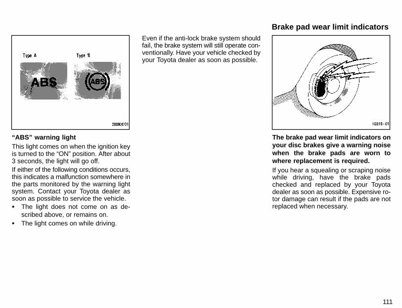
111
“ABS” warning lightThis light comes on when the ignition keyis turned to the “ON” position. After about3 seconds, the light will go off.If either of the following conditions occurs,this indicates a malfunction somewhere inthe parts monitored by the warning lightsystem. Contact your Toyota dealer assoon as possible to service the vehicle.� The light does not come on as de-
scribed above, or remains on.� The light comes on while driving.
Even if the anti-lock brake system shouldfail, the brake system will still operate con-ventionally. Have your vehicle checked byyour Toyota dealer as soon as possible.
The brake pad wear limit indicators onyour disc brakes give a warning noisewhen the brake pads are worn towhere replacement is required.If you hear a squealing or scraping noisewhile driving, have the brake padschecked and replaced by your Toyotadealer as soon as possible. Expensive ro-tor damage can result if the pads are notreplaced when necessary.
Brake pad wear limit indicators
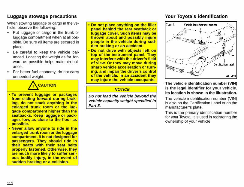
112
When stowing luggage or cargo in the ve-hicle, observe the following:� Put luggage or cargo in the trunk or
luggage compartment when at all pos-sible. Be sure all items are secured inplace.
� Be careful to keep the vehicle bal-anced. Locating the weight as far for-ward as possible helps maintain bal-ance.
� For better fuel economy, do not carryunneeded weight.
CAUTION!
� To prevent luggage or packagesfrom sliding forward during brak-ing, do not stack anything in theenlarged trunk room or the lug-gage compartment higher than theseatbacks. Keep luggage or pack-ages low, as close to the floor aspossible.
� Never allow anyone to ride in theenlarged trunk room or the luggagecompartment. It is not designed forpassengers. They should ride intheir seats with their seat beltsproperly fastened. Otherwise, theyare much more likely to suffer seri-ous bodily injury, in the event ofsudden braking or a collision.
� Do not place anything on the fillerpanel behind the rear seatback orluggage cover. Such items may bethrown about and possibly injurepeople in the vehicle during sud-den braking or an accident.
� Do not drive with objects left ontop of the instrument panel. Theymay interfere with the driver’s fieldof view. Or they may move duringsharp vehicle acceleration or turn-ing, and impair the driver’s controlof the vehicle. In an accident theymay injure the vehicle occupants.
Do not load the vehicle beyond thevehicle capacity weight specified inPart 8.
NOTICEThe vehicle identification number (VIN)is the legal identifier for your vehicle.Its location is shown in the illustration.The vehicle indentification number (VIN)is also on the Certification Label or on themanufacturer’s plate.This is the primary identification numberfor your Toyota. It is used in registering theownership of your vehicle.
Luggage stowage precautions Your Toyota’s identification
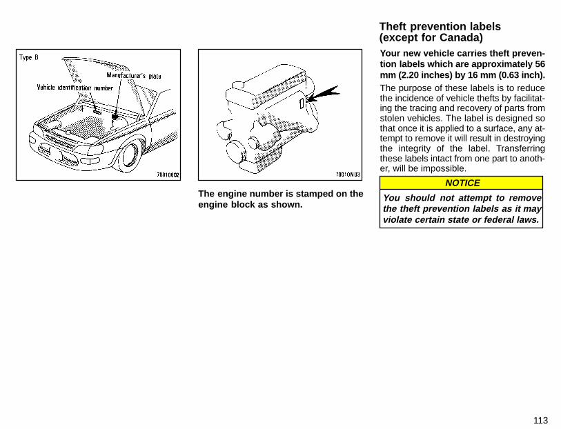
113
The engine number is stamped on theengine block as shown.
Your new vehicle carries theft preven-tion labels which are approximately 56mm (2.20 inches) by 16 mm (0.63 inch).The purpose of these labels is to reducethe incidence of vehicle thefts by facilitat-ing the tracing and recovery of parts fromstolen vehicles. The label is designed sothat once it is applied to a surface, any at-tempt to remove it will result in destroyingthe integrity of the label. Transferringthese labels intact from one part to anoth-er, will be impossible.
You should not attempt to removethe theft prevention labels as it mayviolate certain state or federal laws.
NOTICE
Theft prevention labels(except for Canada)
114
CAUTION!
Do not modify the suspension/chas-sis with lift kits, spacers, etc. It cancause dangerous handling charac-teristics, resulting in the loss of con-trol.
Determine what kind of tires your ve-hicle is originally equipped with.1. Summer tiresSummer tires are high-speed capabilitytires best suited to highway driving underdry conditions.Since summer tires do not have the sametraction performance as snow tires, sum-mer tires are inadequate for driving onsnow-covered or icy roads. For driving onsnow-covered or icy roads, we recom-mend using snow tires. If installing snowtires, be sure to replace all four tires.2. All season tiresAll season tires are designed to providebetter traction in snow and to be adequatefor driving in most winter conditions, aswell as for use all year round.All season tires, however, do not have ad-equate traction performance comparedwith snow tires in heavy or loose snow.Also, all season tires fall short in accelera-tion and handling performance comparedwith summer tires in highway driving.
CAUTION!
� Do not mix summer and all seasontires on your vehicle as this cancause dangerous handling char-acteristics, resulting in loss ofcontrol.
� Do not use tire other than themanufacturer’s designated tires,and do not mix tires or wheels ofthe sizes different from the origi-nals.
Types of tiresSuspension and chassis
Part 3How to start the engine—(a) Before crankingBefore starting the engine
115
STARTING ANDDRIVING
� Before starting the engine� How to start the engine� Tips for driving in various
conditions� Winter driving tips� Trailer towing� How to save fuel and make your
vehicle last longer, too
1. Check the area around the vehicle be-fore entering it.2. Adjust seat position, seatback angle,head restraint height and steering wheelangle.3. Adjust inside and outside rear viewmirrors.4. Lock all doors.5. Fasten seat belts.
1. Apply the parking brake firmly.2. Turn off unnecessary lights and acces-sories.3. Manual transmission: Press theclutch pedal to the floor and shift thetransmission into neutral. Hold the clutchpedal to the floor until the engine isstarted. A starter safety device will pre-vent the starter from operating if theclutch pedal is not fully depressed.Automatic transmission: Put the selec-tor lever in “P”. If you need to restart theengine while the vehicle is moving, put theselector lever in “N”. A starter safety de-vice will prevent the starter from operatingif the selector lever is in any drive position.4. Automatic transmission only: De-press the brake pedal and hold it to thefloor until driving off.
116
Before starting the engine, be sure to fol-low the instructions in “(a) Before crank-ing”.Normal starting procedureThe multiport fuel injection system/se-quential multiport fuel injection system inyour engine automatically controls theproper air-fuel mixture for starting. Youcan start a cold or hot engine as follows:1. With your foot off the accelerator ped-al, crank the engine by turning the key to“START”. Release it when the enginestarts.2. After the engine runs for about 10 sec-onds, you are ready to drive.If the weather is below freezing, let the en-gine warm up for a few minutes beforedriving.If the engine stalls...Simply restart it, using the correct proce-dure given in normal starting.If the engine will not start—See “If your vehicle will not start” in Part 4.
�Do not crank for more than 15 sec-onds at a time. This may overheatthe starter and wiring systems.
�Do not race a cold engine.�If the engine becomes difficult to
start or stalls frequently, have theengine checked immediately.
NOTICE
� Always slow down in gusty cross-winds. This will allow you much bettercontrol
� Drive slowly onto curbs and, if pos-sible, at a right angle. Avoid drivingonto high, sharp-edged objects andother road hazards. Failure to do socan lead to severe tire damage result-ing in tire bursts.
� When parking on a hill, turn the frontwheels until they touch the curb so thatthe vehicle will not roll. Apply the park-ing brake, and place the transmissionin “P” (automatic) or in first or reverse(manual). If necessary, block thewheels.
� Washing your vehicle or drivingthrough deep water may get thebrakes wet. To see whether they arewet, check that there is no traffic nearyou, and then press the pedal lightly. Ifyou do not feel a normal braking force,the brakes are probably wet. To drythem, drive the vehicle cautiouslywhile lightly pressing the brake pedalwith the parking brake pulled. If theystill do not work safely, pull to the sideof the road and call a Toyota dealer forassistance.
CAUTION!� Before driving off, make sure the
parking brake is fully released andthe parking brake reminder light isoff.
� Do not leave your vehicle unat-tended while the engine is run-ning.
� Do not rest your foot on the brakepedal while driving. It can causedangerous overheating, needlesswear, and poor fuel economy.
� To drive down a long or steep hill,reduce your speed and downshift.Remember, if you ride the brakesexcessively, they may overheatand not work properly.
� Be careful when accelerating, up-shifting, downshifting or brakingon a slippery surface. Sudden ac-celeration or engine braking couldcause the vehicle to spin or skid.
(b) Starting the engineTips for drivingin various conditions
117
� Do not drive in excess of the speedlimit. Even if the legal speed limitpermits it, do not drive over 140km/h (85 mph) unless your vehiclehas high-speed capability tires.Driving over 140 km/h (85 mph)may result in tire failure, loss ofcontrol and possible injury. Besure to consult a tire dealer to de-termine whether the tires on yourvehicle are high-speed capabilitytires or not before driving at suchspeeds.
� Do not continue normal drivingwhen the brakes are wet. If theyare wet, your vehicle will require alonger stopping distance, and itmay pull to one side when thebrakes are applied. Also, the park-ing brake will not hold the vehiclesecurely.
Make sure you have ethylene-glycolantifreeze in the radiator.
Do not use alcohol type antifreeze.
NOTICE
Check the condition of the battery andcables.Cold temperatures reduce the capacity ofany battery, so it must be in top shape toprovide enough power for winter starting.Chapter 7-3 tells you how to visually in-spect the battery. Your Toyota dealer andmost service stations will be pleased tocheck the level of charge.Make sure the engine oil viscosity issuitable for the cold weather.See Chapter 7-2 for recommended vis-cosity. Leaving a heavy summer oil in yourvehicle during winter months may causeharder starting. If you are not sure aboutwhich oil to use, call your Toyota deal-er—he will be pleased to help.Keep the door locks from freezing.Squirt lock de-icer or glycerine into thelocks to keep them from freezing. To opena frozen lock, try heating the key before in-serting it.
Use a washer fluid containing an anti-freeze solution.This product is available at your Toyotadealer and most auto parts stores. Followthe manufacturer’s directions for howmuch to mix with water.
Do not use engine antifreeze or anyother substitute as washer fluid be-cause it may damage your vehicle’spaint.
NOTICE
Do not use your parking brake whenthere is a possibility it could freeze.When parking, put the transmission into“P” (automatic) or into first or reverse(manual) and block the rear wheels. Donot use the parking brake, or snow or wa-ter accumulated in and around the parkingbrake mechanism may freeze, making ithard to release.Keep ice and snow from accumulatingunder the fenders.Ice and snow built up under your fenderscan make steering difficult. During badwinter driving, stop and check under thefenders occasionally.
Winter driving tips
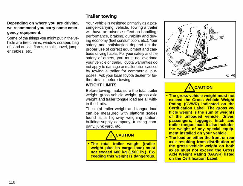
118
Depending on where you are driving,we recommend you carry some emer-gency equipment.Some of the things you might put in the ve-hicle are tire chains, window scraper, bagof sand or salt, flares, small shovel, jump-er cables, etc.
Your vehicle is designed primarily as a pas-senger-carrying vehicle. Towing a trailerwill have an adverse effect on handling,performance, braking, durability and driv-ing economy (fuel consumption, etc.). Yoursafety and satisfaction depend on theproper use of correct equipment and cau-tious driving habits. For your safety and thesafety of others, you must not overloadyour vehicle or trailer. Toyota warranties donot apply to damage or malfunction causedby towing a trailer for commercial pur-poses. Ask your local Toyota dealer for fur-ther details before towing.WEIGHT LIMITSBefore towing, make sure the total trailerweight, gross vehicle weight, gross axleweight and trailer tongue load are all with-in the limits.The total trailer weight and tongue loadcan be measured with platform scalesfound at a highway weighing station,building supply company, trucking com-pany, junk yard, etc.
CAUTION!� The total trailer weight (trailer
weight plus its cargo load) mustnot exceed 680 kg (1500 lb.). Ex-ceeding this weight is dangerous.
CAUTION!� The gross vehicle weight must not
exceed the Gross Vehicle WeightRating (GVWR) indicated on theCertification Label. The gross ve-hicle weight is the sum of weightsof the unloaded vehicle, driver,passengers, luggage, hitch andtrailer tongue load. It also includesthe weight of any special equip-ment installed on your vehicle.
� The load on either the front or rearaxle resulting from distribution ofthe gross vehicle weight on bothaxles must not exceed the GrossAxle Weight Rating (GAWR) listedon the Certification Label.
Trailer towing
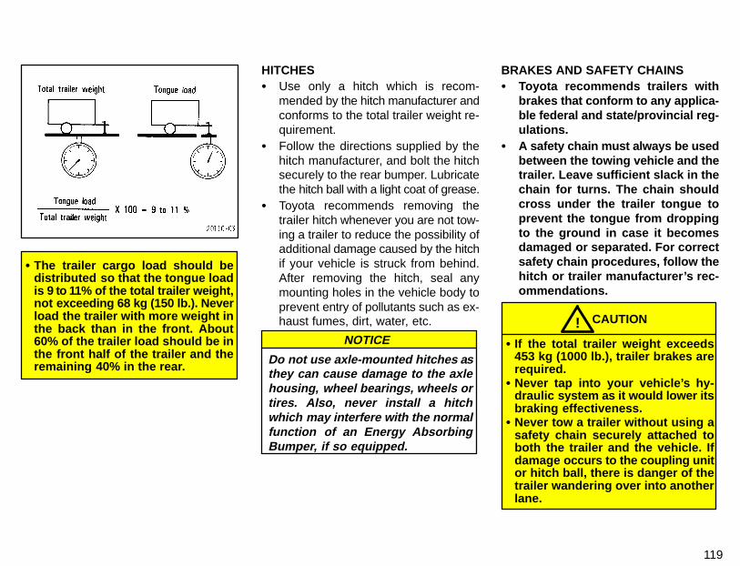
119
� The trailer cargo load should bedistributed so that the tongue loadis 9 to 11% of the total trailer weight,not exceeding 68 kg (150 lb.). Neverload the trailer with more weight inthe back than in the front. About60% of the trailer load should be inthe front half of the trailer and theremaining 40% in the rear.
HITCHES� Use only a hitch which is recom-
mended by the hitch manufacturer andconforms to the total trailer weight re-quirement.
� Follow the directions supplied by thehitch manufacturer, and bolt the hitchsecurely to the rear bumper. Lubricatethe hitch ball with a light coat of grease.
� Toyota recommends removing thetrailer hitch whenever you are not tow-ing a trailer to reduce the possibility ofadditional damage caused by the hitchif your vehicle is struck from behind.After removing the hitch, seal anymounting holes in the vehicle body toprevent entry of pollutants such as ex-haust fumes, dirt, water, etc.
Do not use axle-mounted hitches asthey can cause damage to the axlehousing, wheel bearings, wheels ortires. Also, never install a hitchwhich may interfere with the normalfunction of an Energy AbsorbingBumper, if so equipped.
NOTICE
BRAKES AND SAFETY CHAINS� Toyota recommends trailers with
brakes that conform to any applica-ble federal and state/provincial reg-ulations.
� A safety chain must always be usedbetween the towing vehicle and thetrailer. Leave sufficient slack in thechain for turns. The chain shouldcross under the trailer tongue toprevent the tongue from droppingto the ground in case it becomesdamaged or separated. For correctsafety chain procedures, follow thehitch or trailer manufacturer’s rec-ommendations.
CAUTION!� If the total trailer weight exceeds
453 kg (1000 lb.), trailer brakes arerequired.
� Never tap into your vehicle’s hy-draulic system as it would lower itsbraking effectiveness.
� Never tow a trailer without using asafety chain securely attached toboth the trailer and the vehicle. Ifdamage occurs to the coupling unitor hitch ball, there is danger of thetrailer wandering over into anotherlane.
120
TIRES� Ensure that your vehicle’s tires are
properly inflated. See Chapter 7-2 forinstructions.
� The trailer tires should be inflated tothe pressure recommended by thetrailer manufacturer in respect to thetotal trailer weight.
TRAILER LIGHTS� Trailer lights must comply with federal,
state/provincial and local regulations.See your local recreational vehicledealer or rental agency for the correcttype of wiring and relays for your trail-er. Check for correct operation of theturn signals and stop lights each timeyou hitch up. Direct splicing may dam-age your vehicle’s electrical systemand cause a malfunction of your lights.
BREAK-IN SCHEDULE� Toyota recommends that you do not
tow a trailer with a new vehicle or a ve-hicle with any new power train compo-nent (engine, transmission, differen-tial, wheel bearing, etc.) for the first800 km (500 miles) of driving.
MAINTENANCE� If you tow a trailer, your vehicle will re-
quire more frequent maintenance dueto the additional load. For this informa-tion, please refer to the scheduledmaintenance information in the “Own-er’s Manual Supplement/MaintenanceSchedule”.
� Retighten all fixing bolts of the towingball and bracket after approximately1000 km (600 miles) of trailer driving.
PRE-T OWING SAFETY CHECK� Check that your vehicle remains level
when a loaded or unloaded trailer ishitched. Do not drive if the vehicle hasan abnormal nose-up or nose-downcondition, and check for impropertongue load, overload, worn suspen-sion or other possible causes.
� Make sure the trailer cargo is securelyloaded so that it cannot shift.
� Check that your rear view mirrors con-form to any applicable federal, state/provincial or local regulation. If not,install the rear view mirrors requiredfor towing purpose.
TRAILER TOWING TIPS
When towing a trailer, your vehicle willhandle differently than when not tow-ing. The three main causes of vehicle-trailer accidents are driver error, ex-cessive speed and improper trailerloading. Keep these in mind when tow-ing:� Before starting out, check operation of
the lights and all vehicle-trailer con-nections. After driving a short dis-tance, stop and recheck the lights andconnections. Before actually towing atrailer, practice turning, stopping andbacking with a trailer in an area awayfrom traffic until you learn the feel.
� Backing with a trailer is difficult and re-quires practice. Grip the bottom of thesteering wheel and move your hand tothe left to move the trailer to the left.Move your hand to the right to movethe trailer to the right. (This procedureis generally opposite to that whenbacking without a trailer). Also, justturn the steering wheel a little at a time,avoiding sharp or prolonged turning.Have someone guide you when back-ing to reduce the risk of an accident.
121
� Because stopping distance may be in-creased, vehicle-to-vehicle distanceshould be increased when towing atrailer. For each 16 km/h (10 mph) ofspeed, allow at least one vehicle andtrailer length between you and the ve-hicle ahead. Avoid sudden braking asyou may skid, resulting in jackknifingand loss of control. This is especiallytrue on wet or slippery surfaces.
� Avoid jerky starts or sudden accelera-tion. If your vehicle has manual trans-mission, prevent excessive clutch slip-page by keeping engine rpm low andnot racing the engine. Always start outin first gear.
� Avoid jerky steering and sharp turns.The trailer could hit your vehicle in atight turn. Slow down before making aturn to avoid the necessity of suddenbraking.
� Remember that when making a turn,the trailer wheels will be closer thanthe vehicle wheels to the inside of theturn. Therefore, compensate for thisby making a larger than normal turningradius with your vehicle.
� Crosswinds and rough roads will ad-versely affect handling of your vehicleand trailer, causing sway. Pay atten-tion to the rear from time to time to pre-pare yourself for being passed by largetrucks or buses, which may cause yourvehicle and trailer to sway. If swayinghappens, firmly grip the steering wheeland reduce speed immediately butgradually. Never increase speed.Steer straight ahead. If you make noextreme correction with the steering orbrakes, the vehicle and trailer will sta-bilize.
� Be careful when passing other ve-hicles. Passing requires considerabledistance. After passing a vehicle, donot forget the length of your trailer andbe sure you have plenty of room be-fore changing lanes.
� In order to maintain engine braking effi-ciency, do not use fifth gear (manualtransmission or overdrive (automatictransmission).
� Because of the added load of the trail-er, your vehicle’s engine may overheaton hot days (at temperatures over30°C [85°F]) when going up a long orsteep grade with a trailer. If the enginecoolant temperatue gauge indicatesoverheating, immediately turn off theair conditioning (if in use), pull off theroad and stop in a safe spot. Refer to“If your vehicle overheats” in Part 4 ofthis manual.
� Always place wheel blocks under boththe vehicle and trailer wheels whenparking. Apply the parking brake firm-ly. Put the transmission in “P” (auto-matic) or in first or reverse (manual).Avoid parking on a slope with a trailer,but if it cannot be avoided, do so onlyafter performing the following:
1. Apply the brakes and hold.2. Have someone place wheel blocks un-der both the vehicle and trailer wheels.3. When the wheel blocks are in place,release your brakes slowly until the blocksabsorb the load.4. Apply the parking brake firmly.5. Shift into first or reverse (manual) or“P” (automatic) and turn off the engine.
122
When restarting out after parking on aslope:1. With the transmission in “P” position(automatic) or the clutch pedal depressed(manual), start the engine. (With an auto-matic transmission, be sure to keep thebrake pedal depressed.)2. Shift into gear.3. Release the parking brake (also footbrake on automatic transmission ve-hicles) and slowly pull or back away fromthe wheels blocks. Stop and apply yourbrakes.4. Have someone retrieve the blocks.
CAUTION!� Do not exceed 72 km/h (45 mph) or
the posted towing speed limit,whichever is lower. Because insta-bility (swaying) of a towing vehicle-trailer combination usually in-creases as the speed increases, ex-ceeding 72 km/h (45 mph) maycause loss of control.
� Slow down and downshift beforedescending steep or long downhillgrades. Do not make sudden down-shifts.
� Avoid holding the brake pedaldown too long or too frequently.This could cause the brakes tooverheat and result in reducedbraking efficiency.
Getting more kilometers/mileage from a li-ter/gallon of fuel is easy—just take it easy.It will help make your vehicle last longer,too. Here are some specific tips on how tosave money on both fuel and repairs:� Keep your tires inflated at the cor-
rect pressure. Underinflation causestire wear and wastes fuel. See Chapter7-2 for instructions.
� Do not carry unneeded weight inyour vehicle. Excess weight puts aheavier load on the engine, causinggreater fuel consumption.
� Avoid lengthy warm-up idling.Once the engine is running smoothly,begin driving—but gently. Remember,however, that on cold winter days thismay take a little longer.
� Accelerate slowly and smoothly.Avoid jackrabbit starts. Get into highgear as quickly as possible.
� Avoid long engine idling. If you havea long wait and you are not in traffic, itis better to turn off the engine and startagain later.
� Avoid engine lug or overrevving.Use a gear position suitable for theroad on which you are travelling.
� Avoid continuous speeding up andslowing down. Stop-and-go drivingwastes fuel.
� Avoid unnecessary stopping andbraking. Maintain a steady pace. Tryto time the traffic signals so you onlyneed to stop as little as possible or takeadvantage of through streets to avoidtraffic lights. Keep a proper distancefrom other vehicles to avoid suddenbraking. This will also reduce wear onyour brakes.
� Avoid heavy traffic or traffic jamswhenever possible.
� Do not rest your foot on the clutchor brake pedal. This causes needlesswear, overheating and poor fuel econ-omy.
� Maintain a moderate speed onhighways. The faster you drive, thegreater the fuel consumption. By re-ducing your speed, you will cut downon fuel consumption.
� Keep the front wheels in properalignment. Avoid hitting the curb andslow down on rough roads. Improperalignment not only causes faster tirewear but also puts an extra load on theengine, which, in turn, wastes fuel.
How to save fuel and make yourvehicle last longer, too
123
� Keep the bottom of your vehiclefree from mud, etc. This not onlylessens weight but also helps preventcorrosion.
� Keep your vehicle tuned-up and intop shape. A dirty air cleaner, carbu-retor out of adjustment, improper valveclearance, dirty plugs, dirty oil andgrease, brakes not adjusted, etc. alllower engine performance and con-tribute to poor fuel economy. For lon-ger life of all parts and lower operatingcosts, keep all maintenance work onschedule, and if you often drive undersevere conditions, see that your ve-hicle receives more frequent mainte-nance. (For scheduled maintenanceinformation, please refer to the sepa-rate “Owner’s Manual Supplement/Maintenance Schedule”).
CAUTION!Never turn off the engine to coastdown hills. Your power steering andbrake booster will not function with-out the engine running. Also, theemission control system operatesproperly only when the engine isrunning.

124
Part 4If your vehicle will not start—(a) Simple checks
125
IN CASE OFAN EMERGENCY
� If your vehicle will not start� If your engine stalls while
driving� If your vehicle overheats� If you have a flat tire� If your vehicle needs to be
towed� If you cannot shift automatic
transmission selector lever� If you lose your keys
Before making these checks, make sureyou have followed the correct starting pro-cedure given in “How to start the engine”in Part 3 and that you have sufficient fuel.If the engine is not turning over or isturning over too slowly—1. Check that the battery terminals aretight and clean.2. If the battery terminals are O.K., switchon the interior light.3. If the light is out, dim or goes out whenthe starter is cranked, the battery is dis-charged. You may try jump starting. See“(c) Jump starting” for further instructions.If the light is O.K., but the engine still willnot start, it needs adjustment or repair.Call a Toyota dealer or qualified repairshop.
NOTICE
Do not pull- or push-start thevehicle. It may damage the vehicleor cause a collision when the enginestarts. Also the three-way catalyticconverter may overheat andbecome a fire hazard.
If the engine turns over at its normalspeed but will not start—1. Check that all the push-on connectorsare tight. (For example, connections atthe spark plugs, ignition coil and/or distrib-utor)2. If the connectors are O.K., the enginemay be flooded because of repeatedcranking. See “(b) Starting a flooded en-gine” for further instructions.
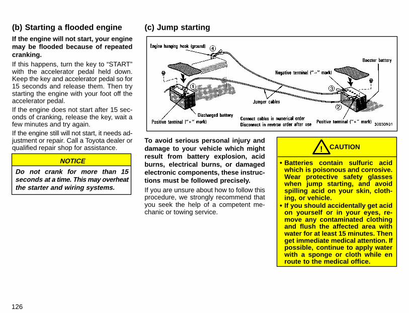
126
If the engine will not start, your enginemay be flooded because of repeatedcranking.If this happens, turn the key to “START”with the accelerator pedal held down.Keep the key and accelerator pedal so for15 seconds and release them. Then trystarting the engine with your foot off theaccelerator pedal.If the engine does not start after 15 sec-onds of cranking, release the key, wait afew minutes and try again.If the engine still will not start, it needs ad-justment or repair. Call a Toyota dealer orqualified repair shop for assistance.
NOTICE
Do not crank for more than 15seconds at a time. This may o verheatthe starter and wiring systems.
To avoid serious personal injury anddamage to your vehicle which mightresult from battery explosion, acidburns, electrical burns, or damagedelectronic components, these instruc-tions must be followed precisely.If you are unsure about how to follow thisprocedure, we strongly recommend thatyou seek the help of a competent me-chanic or towing service.
� Batteries contain sulfuric acidwhich is poisonous and corrosive.Wear protective safety glasseswhen jump starting, and avoidspilling acid on your skin, cloth-ing, or vehicle.
� If you should accidentally get acidon yourself or in your eyes, re-move any contaminated clothingand flush the affected area withwater for at least 15 minutes. Thenget immediate medical attention. Ifpossible, continue to apply waterwith a sponge or cloth while enroute to the medical office.
CAUTION!
(b) Starting a flooded engine (c) Jump starting
127
� The gas normally produced by abattery will explode if a flame orspark is brought near. Use onlystandardized jumper cables anddo not smoke or light a matchwhile jump starting.
NOTICE
The battery used for boosting mustbe 12 V. Do not jump start unlessyou are sure that the booster batteryis correct.
JUMP STARTING PROCEDURE1. If the booster battery is installed inanother vehicle, make sure the vehiclesare not touching. Turn off all unnecessarylights and accessories.2. If required, remove all the vent plugsfrom the booster and discharged batter-ies. Lay a cloth over the open vents on thebatteries. (This helps reduce the explo-sion hazard, personal injuries and burns.)3. If the engine in the vehicle with thebooster battery is not running, start it andlet it run for a few minutes. During jumpstarting, run the engine at about 2000 rpmwith the accelerator pedal lightly de-pressed.
4. Connect the jumper cables in the exactorder shown in the illustration: positiveterminal (“+” mark)-to-positive terminal(“+”mark), and negative terminal (“-”mark)-to-engine or body ground. Notethat you first connect the positive cable tothe discharged battery and then to thebooster battery. Next, connect the nega-tive cable to the booster battery and thento a solid, stationary, unpainted, metallicpoint (e.g. engine hanging hook) awayfrom the battery. Do not connect it to ornear any part that moves when the engineis cranked.
NOTICE
When making the connections, donot lean over the battery oraccidentally let the jumper cables orclamps touch anything except thecorrect battery terminals or theground.
5. Start your engine in the normal way.After starting, run it at about 2000 rpm forseveral minutes with the accelerator ped-al lightly depressed.6. Carefully disconnect the cables in theexact reverse order: the negative cableand then the positive cable.
7. Carefully dispose of the battery covercloths—they may now contain sulfuricacid.8. If removed, replace all the battery ventplugs.If the cause of your battery discharging isnot apparent (for example, lights left on),you should have it checked.
128
If your engine stalls while driving…1. Reduce your speed gradually, keepinga straight line. Move cautiously off theroad to a safe place.2. Turn on your emergency flashers.3. Try starting the engine again.If the engine will not start, see “If your ve-hicle will not start”.
If the engine is not running, thepower assist for the brakes andsteering will not work so steeringand braking will be much harderthan usual.
CAUTION!
If your engine coolant temperaturegauge indicates overheating, if youexperience a loss of power, or if youhear a loud knocking or pinging noise,the engine has probably overheated.You should follow this procedure …1. Pull safely off the road, stop the vehicleand turn on your emergency flashers. Putthe transmission in “P” (automatic) or neu-tral (manual) and apply the parking brake.Turn off the air conditioning if it is beingused.2. If coolant or steam is boiling out of theradiator or reservoir, stop the engine. Waituntil the steam subsides before openingthe hood. If there is no coolant boiling overor steam, leave the engine running andmake sure the electric cooling fan is oper-ating. If it is not, turn the ignition off.
To help avoid personal injury, keepthe hood closed until there is nosteam. Escaping steam or coolant isa sign of very high pressure.
CAUTION!
3. Visually check to see if the engine drivebelt (water pump belt) is broken or loose.Look for obvious coolant leaks from theradiator, hoses, and under the vehicle.However, note that water draining fromthe air conditioning is normal if it has beenused.
When the engine is running, keephands and clothing away from themoving fan and engine drive belts.
CAUTION!
4. If the engine drive belt is broken or thecoolant is leaking, stop the engine imme-diately. Call a Toyota dealer for assis-tance.5. If the engine drive belt is O.K. andthere are no obvious leaks, check thecoolant reservoir. If it is dry, add coolant tothe reservoir while the engine is running.Fill it about half full.
Do not attempt to remove the radia-tor cap when the engine and radiatorare hot. Serious injury could resultfrom scalding hot fluid and steamblown out under pressure.
CAUTION!
6. After the engine coolant temperaturehas cooled to normal, again check thecoolant level in the reservoir. If necessary,bring it up to half full again. Serious cool-ant loss indicates a leak in the system.You should have it checked as soon aspossible at your Toyota dealer.
If your engine stalls whiledriving If your vehicle overheats
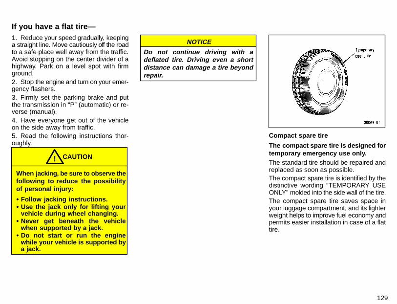
129
1. Reduce your speed gradually, keepinga straight line. Move cautiously off the roadto a safe place well away from the traffic.Avoid stopping on the center divider of ahighway. Park on a level spot with firmground.2. Stop the engine and turn on your emer-gency flashers.3. Firmly set the parking brake and putthe transmission in “P” (automatic) or re-verse (manual).4. Have everyone get out of the vehicleon the side away from traffic.5. Read the following instructions thor-oughly.
When jacking, be sure to observe thefollowing to reduce the possibilityof personal injury:
� Follow jacking instructions.� Use the jack only for lifting your
vehicle during wheel changing.� Never get beneath the vehicle
when supported by a jack.� Do not start or run the engine
while your vehicle is supported bya jack.
CAUTION!
NOTICE
Do not continue driving with adeflated tire. Driving even a shortdistance can damage a tire beyondrepair.
Compact spare tire
The compact spare tire is designed fortemporary emergency use only.The standard tire should be repaired andreplaced as soon as possible.The compact spare tire is identified by thedistinctive wording “TEMPORARY USEONLY” molded into the side wall of the tire.The compact spare tire saves space inyour luggage compartment, and its lighterweight helps to improve fuel economy andpermits easier installation in case of a flattire.
If you have a flat tire—

130
The compact spare tire can be used manytimes, if necessary. It has tread life of upto 4800 km (3000 miles) depending onroad conditions and your driving habits.When tread wear indicators appear on thetire, replace the tire.See also the tire section in Chapter 7-2 fordetails on the tread wear indicators andother service information.
� The compact spare tire was de-signed especially for your Toyota.Do not use it on any other vehicle.
� Do not exceed 80 km/h (50 mph)when driving with the compactspare tire.
CAUTION!
NOTICE
Your ground clearance is reducedwhen the compact spare tire isinstalled so avoid driving overobstacles and drive slowly onrough, unpaved roads and speedbumps. Also, do not attempt to gothrough an automatic car wash asthe vehicle may get caught,resulting in damage.
1. Get the tool bag, jack, jack handleand spare tire.To prepare yourself for an emergency,you should familiarize yourself with theuse of the jack, each of the tools and theirstorage locations.
—Required tools and spare tire
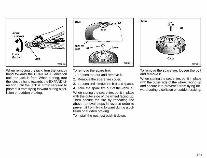
131
When removing the jack, turn the joint byhand towards the CONTRACT directionuntil the jack is free. When storing, turnthe joint by hand towards the EXPAND di-rection until the jack is firmly secured toprevent it from flying forward during a col-lision or sudden braking.
To remove the spare tire:1. Loosen the nut and remove it.2. Remove the spare tire cover.3. Loosen and remove the bolt and spacer.4. Take the spare tire out of the vehicle.When storing the spare tire, put it in placewith the outer side of the wheel facing up.Then secure the tire by repeating theabove removal steps in reverse order toprevent it from flying forward during a col-lision or sudden braking.To install the nut, just push it down.
To remove the spare tire, loosen the boltand remove it.When storing the spare tire, put it in placewith the outer side of the wheel facing upand secure it to prevent it from flying for-ward during a collision or sudden braking.
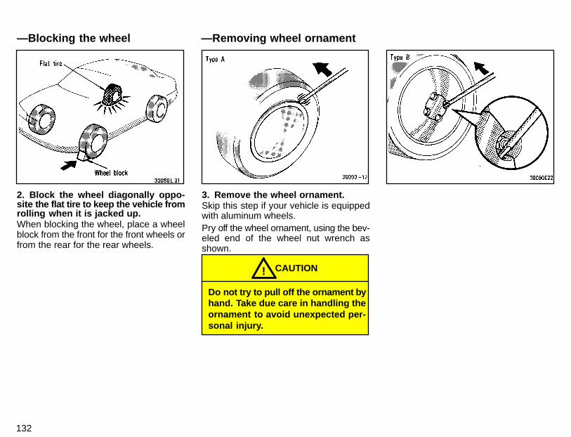
132
2. Block the wheel diagonally oppo-site the flat tire to keep the vehicle fromrolling when it is jacked up.When blocking the wheel, place a wheelblock from the front for the front wheels orfrom the rear for the rear wheels.
3. Remove the wheel ornament.Skip this step if your vehicle is equippedwith aluminum wheels.Pry off the wheel ornament, using the bev-eled end of the wheel nut wrench asshown.
Do not try to pull off the ornament byhand. Take due care in handling theornament to avoid unexpected per-sonal injury.
CAUTION!
—Blocking the wheel —Removing wheel ornament
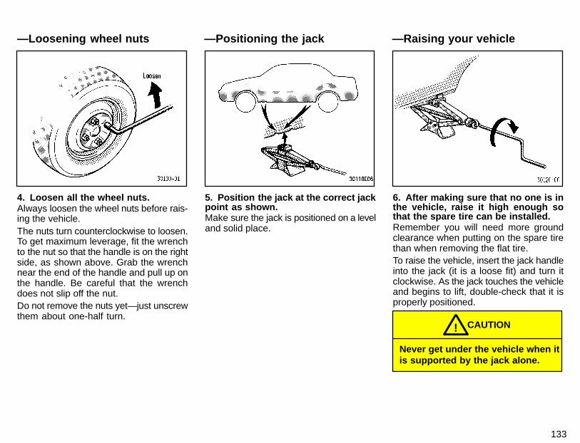
133
4. Loosen all the wheel nuts.Always loosen the wheel nuts before rais-ing the vehicle.The nuts turn counterclockwise to loosen.To get maximum leverage, fit the wrenchto the nut so that the handle is on the rightside, as shown above. Grab the wrenchnear the end of the handle and pull up onthe handle. Be careful that the wrenchdoes not slip off the nut.Do not remove the nuts yet—just unscrewthem about one-half turn.
5. Position the jack at the correct jackpoint as shown.Make sure the jack is positioned on a leveland solid place.
6. After making sure that no one is inthe vehicle, raise it high enough sothat the spare tire can be installed.Remember you will need more groundclearance when putting on the spare tirethan when removing the flat tire.To raise the vehicle, insert the jack handleinto the jack (it is a loose fit) and turn itclockwise. As the jack touches the vehicleand begins to lift, double-check that it isproperly positioned.
Never get under the vehicle when itis supported by the jack alone.
CAUTION!
—Loosening wheel nuts —Positioning the jack —Raising your vehicle
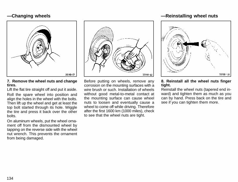
134
7. Remove the wheel nuts and changetires.Lift the flat tire straight off and put it aside.Roll the spare wheel into position andalign the holes in the wheel with the bolts.Then lift up the wheel and get at least thetop bolt started through its hole. Wigglethe tire and press it back over the otherbolts.On aluminum wheels, put the wheel orna-ment off from the dismounted wheel bytapping on the reverse side with the wheelnut wrench. This prevents the ornamentfrom being damaged.
Before putting on wheels, remove anycorrosion on the mounting surfaces with awire brush or such. Installation of wheelswithout good metal-to-metal contact atthe mounting surface can cause wheelnuts to loosen and eventually cause awheel to come off while driving. Thereforeafter the first 1600 km (1000 miles), checkto see that the wheel nuts are tight.
8. Reinstall all the wheel nuts fingertight.Reinstall the wheel nuts (tapered end in-ward) and tighten them as much as youcan by hand. Press back on the tire andsee if you can tighten them more.
—Reinstalling wheel nuts—Changing wheels
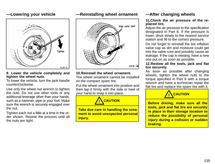
135
9. Lower the vehicle completely andtighten the wheel nuts.To lower the vehicle, turn the jack handlecounterclockwise.Use only the wheel nut wrench to tightenthe nuts. Do not use other tools or anyadditional leverage other than your hands,such as a hammer, pipe or your foot. Makesure the wrench is securely engaged overthe nut.Tighten each nut a little at a time in the or-der shown. Repeat the process until allthe nuts are tight.
10.Reinstall the wheel ornament.The wheel ornament cannot be installedon the compact spare tire.Put the wheel ornament into position andthen tap it firmly with the side or heel ofyour hand to snap it into place.
Take due care in handling the orna-ment to avoid unexpected personalinjury.
CAUTION!
11.Check the air pressure of the re-placed tire.Adjust the air pressure to the specificationdesignated in Part 8. If the pressure islower, drive slowly to the nearest servicestation and fill to the correct pressure.Do not forget to reinstall the tire inflationvalve cap as dirt and moisture could getinto the valve core and possibly cause airleakage. If the cap is missing, have a newone put on as soon as possible.12.Restow all the tools, jack and flattire securely.As soon as possible after changingwheels, tighten the wheel nuts to thetorque specified in Part 8 with a torquewrench and have a technician repair theflat tire and replace the spare tire with it.
Before driving, make sure all thetools, jack and flat tire are securelyin place in their storage location toreduce the possibility of personalinjury during a collision or suddenbraking.
CAUTION!
—After changing wheels—Lowering your vehicle —Reinstalling wheel ornament
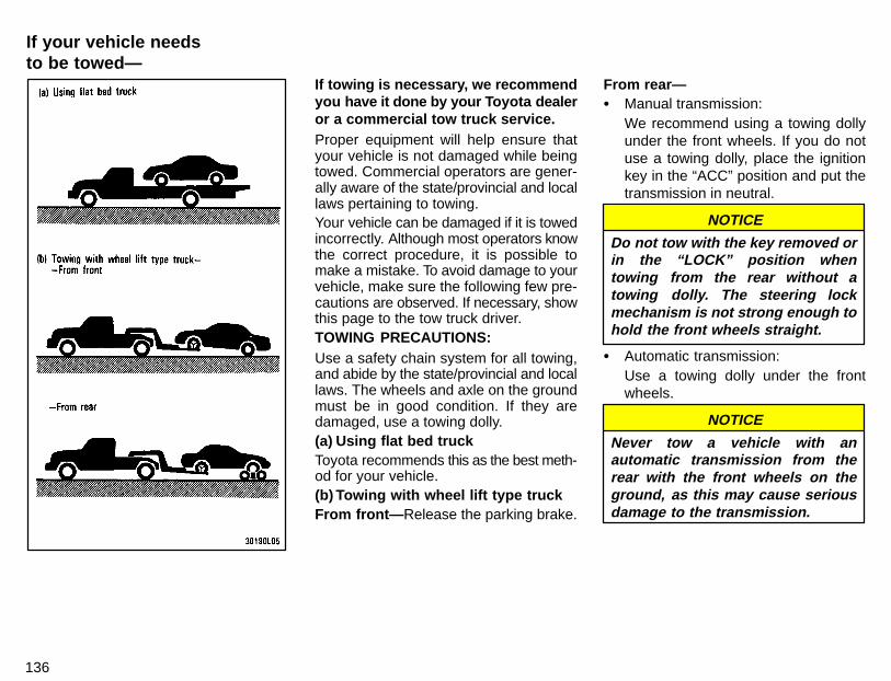
136
If towing is necessary, we recommendyou have it done by your T oyota dealeror a commercial tow truck service.Proper equipment will help ensure thatyour vehicle is not damaged while beingtowed. Commercial operators are gener-ally aware of the state/provincial and locallaws pertaining to towing.Your vehicle can be damaged if it is towedincorrectly. Although most operators knowthe correct procedure, it is possible tomake a mistake. To avoid damage to yourvehicle, make sure the following few pre-cautions are observed. If necessary, showthis page to the tow truck driver.TOWING PRECAUTIONS:Use a safety chain system for all towing,and abide by the state/provincial and locallaws. The wheels and axle on the groundmust be in good condition. If they aredamaged, use a towing dolly.(a) Using flat bed truckToyota recommends this as the best meth-od for your vehicle.(b) Towing with wheel lift type truckFrom front— Release the parking brake.
From rear—� Manual transmission:
We recommend using a towing dollyunder the front wheels. If you do notuse a towing dolly, place the ignitionkey in the “ACC” position and put thetransmission in neutral.
NOTICE
Do not tow with the key removed orin the “LOCK” position whentowing from the rear without atowing dolly. The steering lockmechanism is not strong enough tohold the front wheels straight.
� Automatic transmission:Use a towing dolly under the frontwheels.
NOTICE
Never tow a vehicle with anautomatic transmission from therear with the front wheels on theground, as this may cause seriousdamage to the transmission.
If your vehicle needsto be towed—
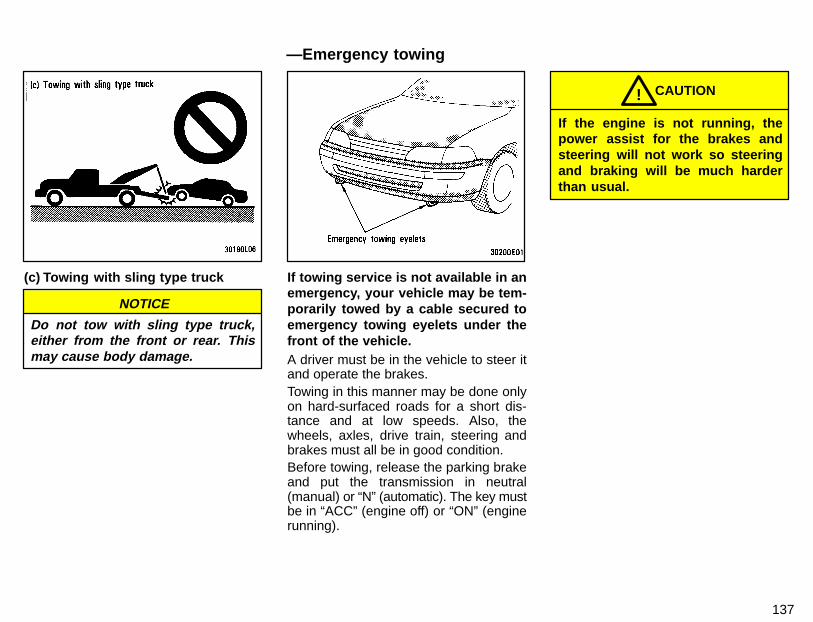
137
(c) Towing with sling type truck
NOTICE
Do not tow with sling type truck,either from the front or rear. Thismay cause body damage.
If towing service is not available in anemergency, your vehicle may be tem-porarily towed by a cable secured toemergency towing eyelets under thefront of the vehicle.A driver must be in the vehicle to steer itand operate the brakes.Towing in this manner may be done onlyon hard-surfaced roads for a short dis-tance and at low speeds. Also, thewheels, axles, drive train, steering andbrakes must all be in good condition.Before towing, release the parking brakeand put the transmission in neutral(manual) or “N” (automatic). The key mustbe in “ACC” (engine off) or “ON” (enginerunning).
CAUTION!
If the engine is not running, thepower assist for the brakes andsteering will not work so steeringand braking will be much harderthan usual.
—Emergency towing
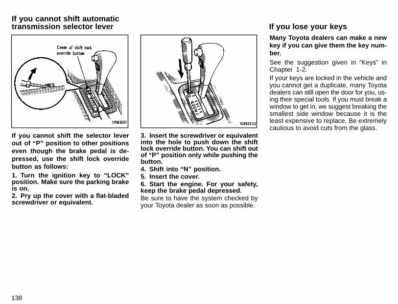
138
If you cannot shift the selector leverout of “P” position to other positionseven though the brake pedal is de-pressed, use the shift lock overridebutton as follows:1. Turn the ignition key to “LOCK”position. Make sure the parking brakeis on.2. Pry up the cover with a flat-bladedscrewdriver or equivalent.
3. Insert the screwdriver or equivalentinto the hole to push down the shiftlock override button. You can shift outof “P” position only while pushing thebutton.4. Shift into “N” position.5. Insert the cover.6. Start the engine. For your safety,keep the brake pedal depressed.Be sure to have the system checked byyour Toyota dealer as soon as possible.
Many Toyota dealers can make a newkey if you can give them the key num-ber.See the suggestion given in “Keys” inChapter 1-2.If your keys are locked in the vehicle andyou cannot get a duplicate, many Toyotadealers can still open the door for you, us-ing their special tools. If you must break awindow to get in, we suggest breaking thesmallest side window because it is theleast expensive to replace. Be extremelycautious to avoid cuts from the glass.
If you cannot shift automatictransmission selector lever If you lose your keys
Part 5Protecting your Toyotafrom corrosion
139
CORROSIONPREVENTION ANDAPPEARANCECARE
� Protecting your Toyota fromcorrosion
� Washing and waxing yourToyota
� Cleaning the interior
Toyota, through its diligent research, de-sign and use of the most advancedtechnology available, has done its part tohelp prevent corrosion and has providedyou with the finest quality vehicleconstruction. Now, it is up to you. Propercare of your Toyota can help ensure long-term corrosion prevention.The most common causes of corro-sion to your vehicle are:� The accumulation of road salt, dirt and
moisture in hard-to-reach areas un-der the vehicle.
� Chipping of paint, or undercoatingcaused by minor accidents or bystones and gravel.
Care is especially important if you livein particular areas or operate your ve-hicle under certain environmentalconditions:� Road salt or dust control chemicals will
accelerate corrosion, as will the pres-ence of salt in the air near the sea-coast or in areas of industrial pollution.
� High humidity accelerates corrosionespecially when temperatures rangejust above the freezing point.
� Wetness or dampness to certain partsof your vehicle for an extended periodof time, may cause corrosion eventhough other parts of the vehicle maybe dry.
� High temperatures will cause corro-sion to those components of the ve-hicle which are prevented from quick-drying due to lack of proper ventilation.
The above signifies the necessity to keepyour vehicle, particularly the underside,as clean as possible and to repair anydamage to paint or protective coatings assoon as possible.To help prevent corrosion on your To-yota, follow these guidelines:Wash your vehicle frequently. It is, ofcourse, necessary to keep your vehicleclean by regular washing, but to preventcorrosion, the following points should beobserved:� If you drive on salted roads in the win-
ter or if you live near the ocean, youshould hose off the undercarriage atleast once a month to minimize corro-sion.
� High pressure water or steam is effec-tive for cleaning the vehicle’s under-side and wheel housings. Pay particu-lar attention to these areas as it isdifficult to see all the mud and dirt. Itwill do more harm than good to simplywet the mud and debris without remov-ing them. The lower edge of doors,rocker panels and frame membershave drain holes which should not beallowed to clog with dirt as trapped wa-ter in these areas can cause corrosion.
140
� Wash the underside of the vehiclethoroughly when winter is over.
See “Washing and waxing your Toyota”for more tips.Check the condition of your vehicle’spaint and trim. If you find any chips orscratches in the paint, touch them up im-mediately to prevent corrosion from start-ing. If the chips or scratches have gonethrough the bare metal, have a qualifiedbody shop make the repair.Check the interior of your vehicle. Wa-ter and dirt can accumulate under the floormats and could cause corrosion. Occa-sionally check under the mats to make surethe area is dry. Be particularly careful whentransporting chemicals, cleansers, fertiliz-ers, salt, etc; these should be transportedin proper containers. If a spill or leak shouldoccur, immediately clean and dry the area.Use mud shields on your wheels. If youdrive on salted or gravel roads, mudshields help protect your vehicle. Full-size shields, which come as near to theground as possible, are the best. We rec-ommend that the fittings and the areawhere the shields are installed be treatedto resist corrosion. Your Toyota dealer willbe happy to assist in supplying and instal-ling the shields if they are recommendedfor your area.
Do not park your vehicle in a damp,poorly ventilated garage. If you washyour vehicle in the garage, or if you driveit in covered with water or snow, your ga-rage may be so damp it will cause corro-sion. Even if your garage is heated, a wetvehicle can corrode if the ventilation ispoor.
Washing your Toyota by hand
Work in the shade and wait until the ve-hicle body is not hot to the touch.1. Rinse off loose dirt with a hose. Re-move any mud or road salt from the un-derside of the vehicle or in the wheelwells.2. Wash with a mild car-wash soap,mixed according to the manufacturer’s in-structions. Use a soft cotton mitt and keepit wet by dipping it frequently into the washwater. Do not rub hard—let the soap andwater remove the dirt.Aluminum wheels: Use only a mild soap orneutral detergent.Plastic bumpers: Wash carefully. Do notscrub with abrasive cleaners. The bumperfaces are soft.Road tar: Remove with turpentine orcleaners that are marked safe for paintedsurfaces.
Do not use gasoline or strongsolvents, which may be toxic orcause damage.
NOTICE
3.Rinse thoroughly—dried soap can causestreaking. In hot weather you may need torinse each section right after you wash it.
Washing and waxing yourToyota
141
4. To prevent water spots, dry the vehicleusing a clean soft cotton towel. Do not rubor press hard—you might scratch thepaint.Automatic car washYour vehicle may be washed in an auto-matic car wash, but remember that thepaint can be scratched by some type ofbrushes, unfiltered washing water, or thewashing process itself. Scratching re-duces paint durability and gloss, especial-ly on darker colors. The manager of thecar wash should be able to advise youwhether the process is safe for the painton your vehicle.Waxing your Toyota
Polishing and waxing is recommend-ed to maintain the original beauty ofyour Toyota’s finish.1. Always wash and dry the vehicle be-fore you begin waxing, even if you are us-ing a combined cleaner and wax.2. Use a good quality polish and wax. Ifthe finish has become extremely weath-ered, use a car-cleaning polish, followedby a separate wax. Carefully follow themanufacturer’s instructions and precau-tions. Be sure to polish and wax thechrome trim as well as the paint.
3. Wax the vehicle again when waterdoes not bead but remains on the surfacein large patches.
Always remove the plastic bumpersif your vehicle is re-painted andplaced in a high heat paint waxingbooth. High temperatures coulddamage the bumpers.
NOTICE
CAUTION!Do not wash the vehicle floor with wa-ter, or allow water to get onto the floorwhen cleaning the vehicle interior orexterior. Water may get into audiocomponents or other electrical com-ponents above or under the floor car-pet (or mat) and cause a malfunction;and it may cause body corrosion.
Vinyl interior
The vinyl upholstery may be easilycleaned with a mild soap or detergentand water.First vacuum over the upholstery to removeloose dirt. Then, using a sponge or softcloth, apply the soap solution to the vinyl.After allowing it to soak in for a few minutesto loosen the dirt, remove the dirt and wipeoff the soap with a clean damp cloth. If allthe dirt does not come off, repeat theprocedure. Commercial foaming- type vinylcleaners are also available which work well.Follow the manufacturer’s instructions.
Do not use solvent, thinner, gasolineor window cleaner on the interior.
NOTICE
Carpets
Use a good foam-type shampoo toclean the carpets.
Cleaning the interior
142
Begin by vacuuming thoroughly to re-move as much dirt as possible. Severaltypes of foam cleaners are available;some are in aerosol cans and others arepowders or liquids which you mix with wa-ter to produce a foam. To shampoo thecarpets, use a sponge or brush to applythe foam. Rub in overlapping circles.Do not apply water—the best results areobtained by keeping the carpet as dry aspossible. Read the shampoo instructionsand follow them closely.Seat belts
The seat belts may be cleaned withmild soap and water or with lukewarmwater.Use a cloth or sponge. As you are clean-ing, check the belts for excessive wear,fraying, or cuts.
Do not use dye or bleach on thebelts—it may weaken them.
NOTICE
Built-in child restraintThe built-in child restraint may becleaned with mild soap and lukewarmwater.
Do not use dye or bleach on thebelts—it may weaken them.
NOTICE
The built-in child restraint pad is at-tached to the child restraint cushionand seatback with fastener tapes. Youcan remove the pad, machine wash itin cold water and tumble dry it on a lowheat setting.
Never bleach or iron the pad, and donot dry clean it.
NOTICE
WindowsThe windows may be cleaned with anyhousehold window cleaner.
When cleaning the inside of thewindows, be careful not to scratch ordamage the heater wires on the rearwindow.
NOTICE
Air conditioning control panel, car au-dio, instrument panel, console panel,and switches
Use a soft damp cloth for cleaning.Soak a clean soft cloth in water or luke-warm water then lightly wipe off any dirt.
�Do not use organic substances(solvents, kerosene, alcohol, gas-oline, etc.) or alkaline or acidicsolutions. These chemicals cancause discoloring, staining orpeeling of the surface.
NOTICE
�If you use cleaners or polishingagents, make sure their ingredi-ents do not include the sub-stances mentioned above.
�If you use a liquid car freshener, donot spill the liquid onto the ve-hicle’s interior surfaces. It maycontain the ingredients mentionedabove. Immediately clean any spillusing the method mentionedabove.
If you have any questions about thecleaning of your Toyota, your localToyota dealer will be pleased toanswer them.
Part 6 Maintenance requirements
143
VEHICLEMAINTENANCEAND CARE
� Maintenance requirements� General maintenance� Does your vehicle need
repairing?
For scheduled maintenanceinformation, please refer to theseparate “Owner’s ManualSupplement/MaintenanceSchedule”.
Your Toyota vehicle has been designedfor fewer maintenance requirements withlonger service intervals to save both yourtime and money. However, each regularmaintenance, as well as day-to-daycare, is more important than ever beforeto ensure smooth, trouble-free, safe, andeconomical drivings.It is the owner’s responsibility to makesure the specified maintenance, includinggeneral maintenance service, is per-formed. Note that both the new vehicleand emission control system warrantiesspecify that proper maintenance and caremust be performed. See Owner’s Guide,Owner’s Manual Supplement or WarrantyBooklet for complete warranty informa-tion.General maintenanceGeneral maintenance items are thoseday-to-day care practices that are impor-tant to your vehicle for proper operation.It is the owner’s responsibility to ensurethat the general maintenance items areperformed regularly.These checks or inspections can be doneeither by yourself or a qualified technician,or if you prefer, your Toyota dealer will bepleased to do them at a nominal cost.Scheduled maintenanceThe scheduled maintenance items listedin the “Owner’s Manual Supplement/Maintenance Schedule” are those re-quired to be serviced at regular intervals.
For details of your maintenance schedule,read the separate “Owner’s Manual Sup-plement/Maintenance Schedule”.It is recommended that any replace-ment parts used for maintenance orfor the repair of the emission controlsystem be Toyota supplied.
The owner may elect to use non-Toyo-ta supplied parts for replacement pur-poses without invalidating the emis-sion control system warranty.However, use of replacement partswhich are not of equivalent quality mayimpair the effectiveness of the emis-sion control systems.
You may also elect to have mainte-nance, replacement, or repair of theemission control devices and systemperformed by any automotive repairestablishment or individual withoutinvalidating this warranty. See Own-er’s Guide, Owner’s Manual Supple-ment or Warranty Booklet for completewarranty information.
Where to go for service?Toyota technicians are well-trained spe-cialists and are kept up to date with the lat-est service information through technicalbulletins, service tips, and in-dealershiptraining programs. They learn to work onToyotas before they work on your vehicle,rather than while they are working on it.
144
You can be confident that your Toyotadealer’s service department performs thebest job to meet the maintenance require-ments on your vehicle—reliably and eco-nomically.Your copy of the repair order is proof thatall required maintenance has been per-formed for warranty coverage. And if anyproblems should arise with your vehiclewhile under warranty, your Toyota dealerwill promptly take care of it. Again, be sureto keep a copy of the repair order for anyservice performed on your Toyota.What about do- it- yourself mainte-nance?Many of the maintenance items are easyto do yourself if you have a little mechani-cal ability and a few basic automotivetools. Simple instructions for how to per-form them are presented in Part 7.If you are a skilled do-it-yourself me-chanic, the Toyota service manuals arerecommended. Please be aware that do-it-yourself maintenance can affect yourwarranty coverage. See Owner’s Guide,Owner’s Manual Supplement or WarrantyBooklet for the details.
Listed below are the general maintenanceitems that should be performed as fre-quently as specified. In addition to check-ing the items listed, if you notice any un-usual noise, smell or vibration, you shouldinvestigate the cause or take your vehicleto your Toyota dealer or a qualified serviceshop immediately. It is recommendedthat any problem you notice be brought tothe attention of your dealer or the qualifiedservice shop for their advice.
Make these checks only whereadequate ventilation can be obtainedif you run the engine.
CAUTION!
OUTSIDE THE VEHICLE
Items listed below should be per-formed from time to time, unlessotherwise specified.
Tire pressureCheck the pressure with a gauge everytwo weeks, or at least once a month. SeeChapter 7-2 for additional information.Tire surface and wheel nutsCheck the tires carefully for cuts, damageor excessive wear. See Chapter 7-2 foradditional information. When checkingthe tires, make sure no nuts are missing,and check the nuts for looseness. Tightenthem if necessary.
Tire rotationRotate the tires every 12000 km (7500miles). See Chapter 7-2 for additional in-formation.Fluid leaksCheck underneath for leaking fuel, oil, wa-ter or other fluid after the vehicle has beenparked for a while. If you smell fuel fumesor notice any leak, have the cause foundand corrected immediately.Doors and engine hoodCheck that all doors including trunk lid orback door operate smoothly and alllatches lock securely. Make sure the en-gine hood secondary latch secures thehood from opening when the primary latchis released.INSIDE THE VEHICLE
Items listed below should be checkedregularly, e.g. while performing peri-odic services, cleaning the vehicle,etc.
LightsMake sure the headlights, stop lights, taillights, turn signal lights, and other lightsare all working. Check headlight aim.Service reminder indicators and warn-ing buzzersCheck that all service reminder indicatorsand warning buzzers function properly.
General maintenance
145
Steering wheelBe alert for changes in steering condition,such as hard steering or strange noise.SeatsCheck that all front seat controls such asseat adjusters, seatback recliner, etc. op-erate smoothly and that all latches locksecurely in any position. Check that thehead restraints move up and downsmoothly and that the locks hold securelyin any latched position. For folding-downrear seatbacks and swing-up rear seatcushion, check that the latches lock se-curely.Seat beltsCheck that the seat belt system such asbuckles, retractors and anchors operateproperly and smoothly. Make sure the beltwebbing is not cut, frayed, worn or dam-aged.Accelerator pedalCheck the pedal for smooth operation anduneven pedal effort or catching.Clutch pedalCheck the pedal for smooth operation.Brake pedalCheck the pedal for smooth operation andthat the pedal has the proper clearance.Check the brake booster function.
BrakesAt a safe place, check that the brakes donot pull to one side when applied.Parking brakeCheck that the lever has the proper traveland that, on a safe incline, your vehicle isheld securely with only the parking brakeapplied.Automatic transmission “Park” mech-anismCheck the lock release button of the se-lector lever for proper and smooth opera-tion. On a safe incline, check that your ve-hicle is held securely with the selectorlever in “P” position and all brakes re-leased.IN THE ENGINE COMPARTMENT
Items listed below should be checkedfrom time to time , e.g. each time whenrefueling.
Washer fluidMake sure there is sufficient fluid in thetank. See Chapter 7-3 for additional infor-mation.Engine coolant levelMake sure the coolant level is betweenthe “FULL” and “LOW” lines on the see-through reservoir when the engine is cold.See Chapter 7-2 for additional informa-tion.
Battery electrolyte levelMake sure the electrolyte level of all bat-tery cells is between upper and lower levellines on the case. Add only distilled waterwhen replenishing. See Chapter 7-3 foradditional information.Brake fluid levelMake sure the brake fluid level is correct.See Chapter 7-2 for additional informa-tion.Engine oil levelCheck the level on the dipstick with the en-gine turned off and the vehicle parked ona level spot. See Chapter 7-2 for addition-al information.Power steering fluid levelCheck the level on the dipstick. The levelshould be in the “HOT” or “COLD” rangedepending on the fluid temperature. SeeChapter 7-2 for additional information.Exhaust systemIf you notice any change in the sound ofthe exhaust or smell exhaust fumes, havethe cause located and corrected immedi-ately. (See engine exhaust cautions inPart 2.)
146
Be on the alert for changes in perfor-mance, sounds, and visual tip-offs that in-dicate service is needed. Some importantclues are as follows:� Engine missing, stumbling, or pinging� Appreciable loss of power� Strange engine noises� A leak under the vehicle (however, wa-
ter dripping from the air conditioningafter use is normal.)
� Change in exhaust sound (This mayindicate a dangerous carbon monox-ide leak. Drive with the windows openand have the exhaust system checkedimmediately.)
� Flat-looking tire; excessive tire squealwhen cornering; uneven tire wear
� Vehicle pulls to one side when drivingstraight on a level road
� Strange noises related to suspensionmovement
� Loss of brake effectiveness; spongyfeeling brake or clutch pedal; pedal al-most touches floor; vehicle pulls to oneside when braking
� Engine coolant temperature continual-ly higher than normal
If you notice any of these clues, take yourvehicle to your Toyota dealer as soon aspossible. It probably needs adjustment orrepair.
Do not continue driving with the ve-hicle unchecked. It could result inserious vehicle damage and possi-bly personal injury.
CAUTION!
Does your vehicle needrepairing?
Part 7
147
DO-IT-YOURSELFMAINTENANCE—
Chapter 7-1Introduction
� Engine compartment overview� Fuse locations� Do-it-yourself service
precautions� Parts and tools
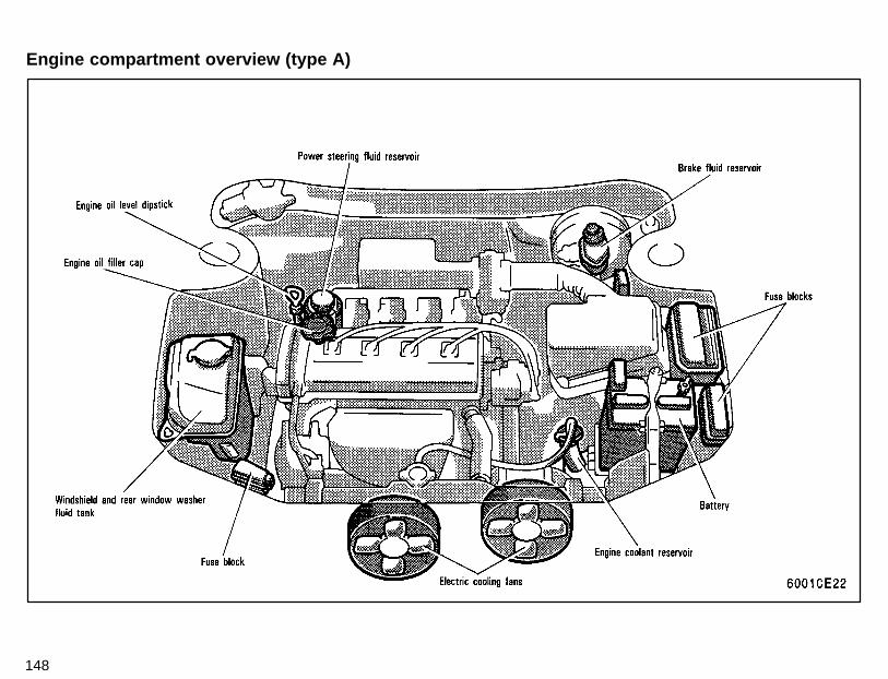
148
Engine compartment overview (type A)
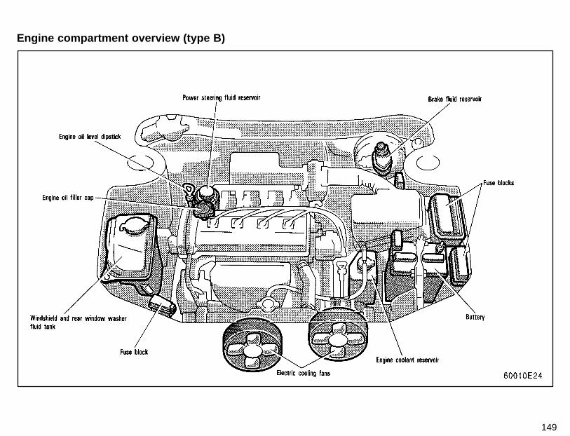
149
Engine compartment overview (type B)
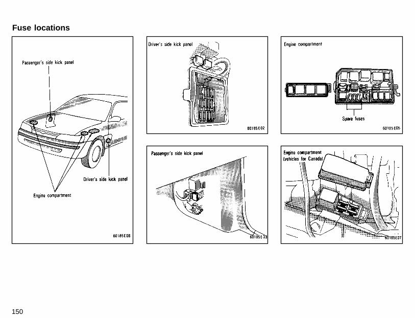
150
Fuse locations
151
If you perform maintenance by your-self, be sure to follow the correct pro-cedure given in this part.You should be aware that improper or in-complete servicing may result in operat-ing problems.Performing do-it-yourself maintenanceduring the warranty period may affectyour warranty coverage. Read the sepa-rate Toyota Warranty statement for detailsand suggestions.This part gives instructions only for thoseitems that are relatively easy for an ownerto perform. As explained in Part 6, thereare still a number of items that must bedone by a qualified technician with specialtools.For information on tools and parts for do-it-yourself maintenance, see “Parts andtools”.Utmost care should be taken when work-ing on your vehicle to prevent accidentalinjury. Here are a few precautions that youshould be especially careful to observe:
� When the engine is running, keephands, clothing, and tools awayfrom the moving fan and enginedrive belts. (Removing rings,watches, and ties is advisable.)
CAUTION!
� Right after driving, the enginecompartment—the engine, radia-tor, exhaust manifold, powersteering fluid reservoir and sparkplug boots, etc.—will be hot. Sobe careful not to touch them. Oil,fluids and spark plugs may also behot.
� If the engine is hot, do not removethe radiator cap or loosen the drainplugs to prevent burning yourself.
� Do not smoke, cause sparks or al-low open flames around fuel or thebattery. Their fumes are flamable.
� Be extremely cautious when work-ing on the battery. It contains poi-sonous and corrosive sulfuricacid.
� Do not get under your vehicle withjust the body jack supporting it. Al-ways use automotive jack standsor other solid supports.
� Be sure that the ignition is off if youwork near the electric cooling fansor radiator grille. With the ignitionon, the electric cooling fan may au-tomatically start to run if the airconditioning is on.
� Use eye protection whenever youwork on or under your vehiclewhere you may be exposed to fly-ing or falling material, fluid spray,etc.
� Used engine oil contains poten-tially harmful contaminants whichmay cause skin disorders such asinflammation or skin cancer, socare should be taken to avoid pro-longed and repeated contact withit. To remove used engine oil fromyour skin, wash thoroughly withsoap and water.
� Do not leave used oil within thereach of children.
� Dispose of used oil and filter onlyin a safe and acceptable manner.Do not dispose of used oil and filterin household trash, in sewers oronto the ground. Call your dealeror a service station for informationconcerning recycling or disposal.
Do-it-yourself serviceprecautions
152
�Remember that battery and igni-tion cables carry high currents orvoltages. Be careful of accidentallycausing a short circuit.
�Add only demineralized or dis-tilled water to fill the radiator. Andif you spill some of the coolant, besure to wash it off with water toprevent it from damaging the partsor paint.
�Do not allow dirt or anything elseto fall through the spark plugholes.
�Do not pry the outer electrode of aspark plug against the center elec-trode.
�Use only spark plugs of the speci-fied type. Using other types willcause engine damage, loss of per-formance or radio noise.
�Do not overfill automatic trans-mission fluid, or the transmissioncould be damaged.
NOTICE �Do not drive with the air cleaner fil-ter removed, or excessive enginewear could result. Also backfiringcould cause a fire in the enginecompartment.
�Be careful not to scratch the glasssurface with the wiper frame.
�When closing the engine hood,check to see that you have not for-gotten any tools, rags, etc.
Here is a list of parts and tools you willneed on performing do-it-yourself main-tenance. Remember all Toyota parts aredesigned in metric sizes, so your toolsmust be metric.Checking the engine oil level
Parts (if level is low):� Engine oil API SH, “Energy-Con-
serving II” multigrade or ILSAC mul-tigrade having viscosity proper foryour climate
Tools:� Rag or paper towel� Funnel (only for adding oil)
Checking the engine coolant levelParts (if level is low):� Ethylene-glycol antifreeze� Demineralized or distilled waterTools:� Funnel (only for adding coolant)
Checking brake fluidParts (if level is low):� SAE J1703 or FMVSS No. 116 DOT
3 brake fluidTools:� Rag or paper towel� Funnel (only for adding fluid)
Parts and tools
153
Checking power steering fluidParts (if level is low):� Automatic transmission fluid
DEXRON -II or-IIITools:� Rag or paper towel� Funnel (only for adding fluid)
Checking battery conditionNon-maintenance batteries—
Tools:� Warm water� Baking soda� Grease� Conventional wrench (for terminal
clamp bolts)Maintenance type batteries—
Parts (if level is low):� Distilled waterTools:� Warm water� Baking soda� Grease� Conventional wrench (for terminal
clamp bolts)� Coin (for vent plugs)� Funnel (only for adding distilled wa-
ter)
Checking and replacing fusesParts (if replacement is necessary):� Fuse with same amperage rating
as originalAdding washer fluid
Parts:� Water� Washer fluid containing antifreeze
(for winter use)Tools:� Funnel
Replacing light bulbsParts:� Bulb with same number and wattage
rating as original (See charts in “Re-placing light bulbs” in Chapter 7-3.)
Tools:� Screwdriver� Wrench

154
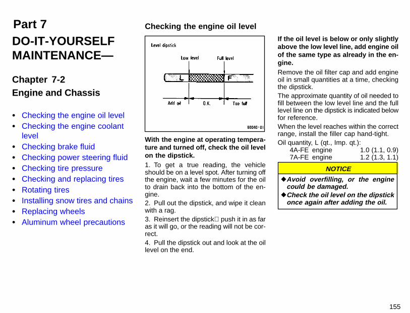
Part 7 Checking the engine oil level
155
DO-IT-YOURSELFMAINTENANCE—
Chapter 7-2Engine and Chassis
� Checking the engine oil level� Checking the engine coolant
level� Checking brake fluid� Checking power steering fluid� Checking tire pressure� Checking and replacing tires� Rotating tires� Installing snow tires and chains� Replacing wheels� Aluminum wheel precautions
With the engine at operating tempera-ture and turned off, check the oil levelon the dipstick.1. To get a true reading, the vehicleshould be on a level spot. After turning offthe engine, wait a few minutes for the oilto drain back into the bottom of the en-gine.2. Pull out the dipstick, and wipe it cleanwith a rag.3. Reinsert the dipstick push it in as faras it will go, or the reading will not be cor-rect.4. Pull the dipstick out and look at the oillevel on the end.
If the oil level is below or only slightlyabove the low level line, add engine oilof the same type as already in the en-gine.Remove the oil filter cap and add engineoil in small quantities at a time, checkingthe dipstick.The approximate quantity of oil needed tofill between the low level line and the fulllevel line on the dipstick is indicated belowfor reference.When the level reaches within the correctrange, install the filler cap hand-tight.Oil quantity, L (qt., Imp. qt.):
4A-FE engine 1.0 (1.1, 0.9)7A-FE engine 1.2 (1.3, 1.1)
NOTICE
�Avoid overfilling, or the enginecould be damaged.
�Check the oil level on the dipstickonce again after adding the oil.

156
ENGINE OIL SELECTIONUse API SH, “Energy-Conserving II” mul-tigrade engine oil or ILSAC multigrade en-gine oil.Recommended viscosity (SAE):
SAE 5W-30 is the best choice for yourvehicle, for good fuel economy, andgood starting in cold weather.
If you use SAE 10W-30 engine oil inextremely low temperatures, the en-gine may become difficult to start, soSAE 5W-30 engine oil is recom-mended.
Oil identification marks
Either or both API registered marks areadded to some oil containers to helpyou select the oil you should use.The API Service Symbol is located any-where on the outside of the container.The top portion of the label shows the oilquality by API (American Petroleum Insti-tute) designations such as SH. The centerportion of the label shows the SAE viscos-ity grade such as SAE 5W-30. “Energy-Conserving II” shown in the lower portion,indicates that the oil has fuel-saving capa-bilities. Oils marked “Energy-ConservingII” will have higher fuel-saving capabilitiesthan oil marked “Energy-Conserving”.
The ILSAC (International Lubricant Stan-dardization and Approval Committee) Cer-tification Mark is displayed on the front ofthe container.

157
Look at the see-through coolant res-ervoir when the engine is cold. Thecoolant level is satisfactory if it is be-tween the “FULL” and “LOW” lines onthe reservoir. If the level is low, addethylene-glycol type coolant.The coolant level in the reservoir will varywith engine temperature. However, if thelevel is on or below the “LOW” line, addcoolant. Bring the level up to the “FULL”line.Use only ethylene-glycol type coolant.See information in the next column.If the coolant level drops within a shorttime after replenishing, there may be aleak in the system. Visually check the ra-diator, hoses, radiator cap and drain cockand water pump.If you can find no leak, have your Toyotadealer test the cap pressure and check forleaks in the cooling system.
CAUTION!To prevent burning yourself, do notremove the radiator cap when the en-gine is hot.
Coolant type selectionYour coolant must contain ethylene-gly-col antifreeze. In addition to preventingfreezing and subsequent damage to theengine, this will also prevent corrosion.Further supplemental inhibitors or addi-tives are neither needed nor recom-mended.Read the antifreeze container for informa-tion on freeze protection. Follow themanufacturer’s directions for how muchto mix with water. The total capacity of thecooling system is given in Part 8. We rec-ommend 50% solution be used for yourToyota, or a sufficient quantity to provideprotection to about -35�C (-31�F).
Do not use alcohol type antifreezeor plain water alone.
NOTICE
To check the fluid level, simply look atthe see-through reservoir. The levelshould be between the “MAX” and“MIN” lines on the reservoir.It is normal for the brake fluid level to godown slightly as the brake pads wear. Sobe sure to keep the reservoir filled.If the reservoir needs frequent refilling, itmay indicate a serious mechanical prob-lem.
Checking brake fluidChecking the engine coolantlevel
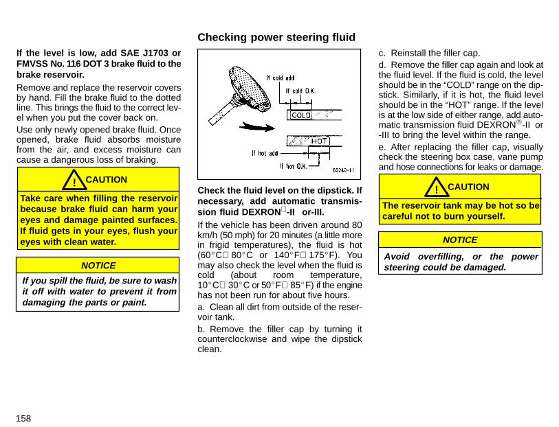
158
If the level is low, add SAE J1703 orFMVSS No. 116 DOT 3 brake fluid to thebrake reservoir.Remove and replace the reservoir coversby hand. Fill the brake fluid to the dottedline. This brings the fluid to the correct lev-el when you put the cover back on.Use only newly opened brake fluid. Onceopened, brake fluid absorbs moisturefrom the air, and excess moisture cancause a dangerous loss of braking.
CAUTION!Take care when filling the reservoirbecause brake fluid can harm youreyes and damage painted surfaces.If fluid gets in your eyes, flush youreyes with clean water.
If you spill the fluid, be sure to washit off with water to prevent it fromdamaging the parts or paint.
NOTICE
Check the fluid level on the dipstick. Ifnecessary, add automatic transmis-sion fluid DEXRON -II or-III.If the vehicle has been driven around 80km/h (50 mph) for 20 minutes (a little morein frigid temperatures), the fluid is hot(60�C 80�C or 140�F 175�F). Youmay also check the level when the fluid iscold (about room temperature,10�C 30�C or 50�F 85�F) if the enginehas not been run for about five hours.a. Clean all dirt from outside of the reser-voir tank.b. Remove the filler cap by turning itcounterclockwise and wipe the dipstickclean.
c. Reinstall the filler cap.d. Remove the filler cap again and look atthe fluid level. If the fluid is cold, the levelshould be in the “COLD” range on the dip-stick. Similarly, if it is hot, the fluid levelshould be in the “HOT” range. If the levelis at the low side of either range, add auto-matic transmission fluid DEXRON�-II or-III to bring the level within the range.e. After replacing the filler cap, visuallycheck the steering box case, vane pumpand hose connections for leaks or damage.
CAUTION!The reservoir tank may be hot so becareful not to burn yourself.
Avoid overfilling, or the powersteering could be damaged.
NOTICE
Checking power steering fluid
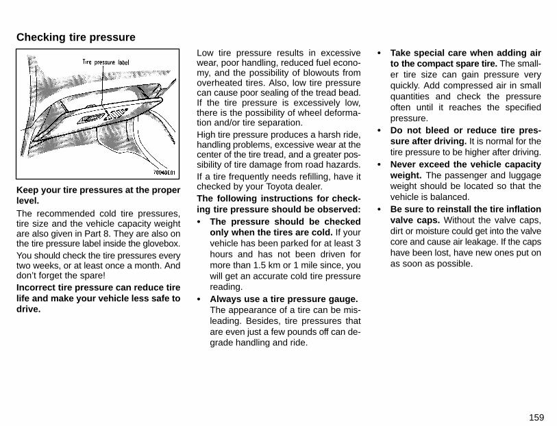
159
Keep your tire pressures at the properlevel.The recommended cold tire pressures,tire size and the vehicle capacity weightare also given in Part 8. They are also onthe tire pressure label inside the glovebox.You should check the tire pressures everytwo weeks, or at least once a month. Anddon’t forget the spare!Incorrect tire pressure can reduce tirelife and make your vehicle less safe todrive.
Low tire pressure results in excessivewear, poor handling, reduced fuel econo-my, and the possibility of blowouts fromoverheated tires. Also, low tire pressurecan cause poor sealing of the tread bead.If the tire pressure is excessively low,there is the possibility of wheel deforma-tion and/or tire separation.High tire pressure produces a harsh ride,handling problems, excessive wear at thecenter of the tire tread, and a greater pos-sibility of tire damage from road hazards.If a tire frequently needs refilling, have itchecked by your Toyota dealer.The following instructions for check-ing tire pressure should be observed:� The pressure should be checked
only when the tires are cold. If yourvehicle has been parked for at least 3hours and has not been driven formore than 1.5 km or 1 mile since, youwill get an accurate cold tire pressurereading.
� Always use a tire pressure gauge. The appearance of a tire can be mis-leading. Besides, tire pressures thatare even just a few pounds off can de-grade handling and ride.
� Take special care when adding airto the compact spare tire. The small-er tire size can gain pressure veryquickly. Add compressed air in smallquantities and check the pressureoften until it reaches the specifiedpressure.
� Do not bleed or reduce tire pres-sure after driving. It is normal for thetire pressure to be higher after driving.
� Never exceed the vehicle capacityweight. The passenger and luggageweight should be located so that thevehicle is balanced.
� Be sure to reinstall the tire inflationvalve caps. Without the valve caps,dirt or moisture could get into the valvecore and cause air leakage. If the capshave been lost, have new ones put onas soon as possible.
Checking tire pressure
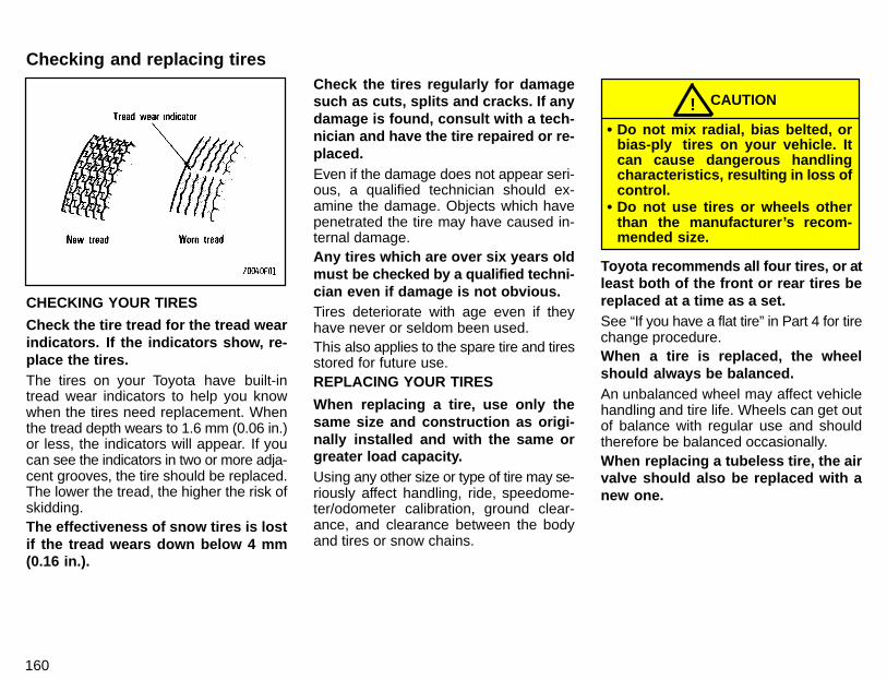
160
CHECKING YOUR TIRES
Check the tire tread for the tread wearindicators. If the indicators show, re-place the tires.The tires on your Toyota have built-intread wear indicators to help you knowwhen the tires need replacement. Whenthe tread depth wears to 1.6 mm (0.06 in.)or less, the indicators will appear. If youcan see the indicators in two or more adja-cent grooves, the tire should be replaced.The lower the tread, the higher the risk ofskidding.The effectiveness of snow tires is lostif the tread wears down below 4 mm(0.16 in.).
Check the tires regularly for damagesuch as cuts, splits and cracks. If anydamage is found, consult with a tech-nician and have the tire repaired or re-placed.Even if the damage does not appear seri-ous, a qualified technician should ex-amine the damage. Objects which havepenetrated the tire may have caused in-ternal damage.Any tires which are over six years oldmust be checked by a qualified techni-cian even if damage is not obvious.Tires deteriorate with age even if theyhave never or seldom been used.This also applies to the spare tire and tiresstored for future use.REPLACING YOUR TIRES
When replacing a tire, use only thesame size and construction as origi-nally installed and with the same orgreater load capacity.Using any other size or type of tire may se-riously affect handling, ride, speedome-ter/odometer calibration, ground clear-ance, and clearance between the bodyand tires or snow chains.
CAUTION!� Do not mix radial, bias belted, or
bias-ply tires on your vehicle. Itcan cause dangerous handlingcharacteristics, resulting in loss ofcontrol.
� Do not use tires or wheels otherthan the manufacturer’s recom-mended size.
Toyota recommends all four tires, or atleast both of the front or rear tires bereplaced at a time as a set.See “If you have a flat tire” in Part 4 for tirechange procedure.When a tire is replaced, the wheelshould always be balanced.An unbalanced wheel may affect vehiclehandling and tire life. Wheels can get outof balance with regular use and shouldtherefore be balanced occasionally.When replacing a tubeless tire, the airvalve should also be replaced with anew one.
Checking and replacing tires
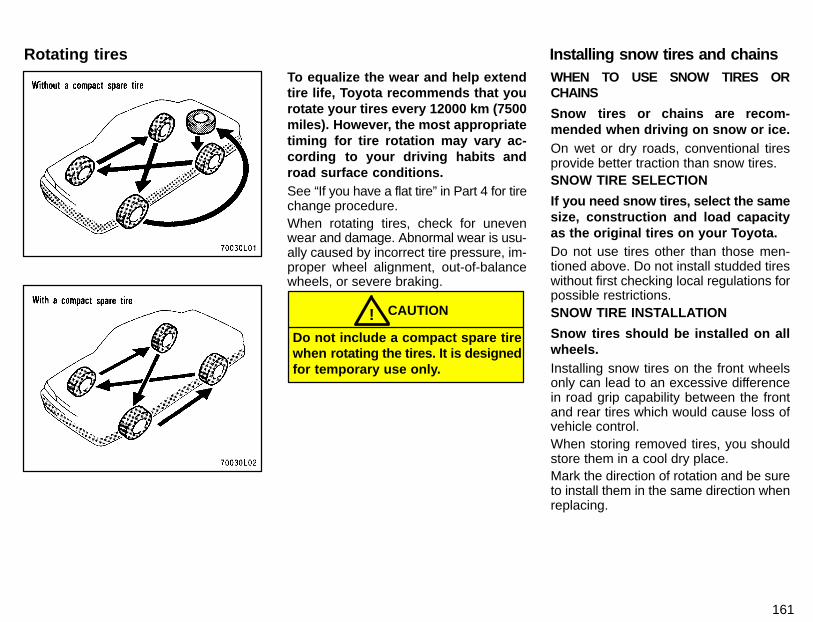
161
To equalize the wear and help extendtire life, Toyota recommends that yourotate your tires every 12000 km (7500miles). However, the most appropriatetiming for tire rotation may vary ac-cording to your driving habits androad surface conditions.See “If you have a flat tire” in Part 4 for tirechange procedure.When rotating tires, check for unevenwear and damage. Abnormal wear is usu-ally caused by incorrect tire pressure, im-proper wheel alignment, out-of-balancewheels, or severe braking.
CAUTION!Do not include a compact spare tirewhen rotating the ti res. It is designedfor temporary use only.
WHEN TO USE SNOW TIRES ORCHAINS
Snow tires or chains are recom-mended when driving on snow or ice.On wet or dry roads, conventional tiresprovide better traction than snow tires.SNOW TIRE SELECTION
If you need snow tires, select the samesize, construction and load capacityas the original tires on your Toyota.Do not use tires other than those men-tioned above. Do not install studded tireswithout first checking local regulations forpossible restrictions.SNOW TIRE INSTALLATION
Snow tires should be installed on allwheels.Installing snow tires on the front wheelsonly can lead to an excessive differencein road grip capability between the frontand rear tires which would cause loss ofvehicle control.When storing removed tires, you shouldstore them in a cool dry place.Mark the direction of rotation and be sureto install them in the same direction whenreplacing.
Installing snow tires and chainsRotating tires
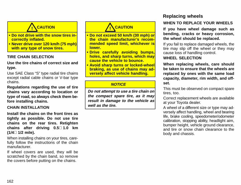
162
CAUTION!� Do not drive with the snow tires in-
correctly inflated.� Never drive over 120 km/h (75 mph)
with any type of snow tires.
TIRE CHAIN SELECTION
Use the tire chains of correct size andtype.Use SAE Class “S” type radial tire chainsexcept radial cable chains or V-bar typechains.Regulations regarding the use of tirechains vary according to location ortype of r oad, so always check them be-fore installing chains.
CHAIN INSTALLATION
Install the chains on the front tires astightly as possible. Do not use tirechains on the rear tires. Retightenchains after driving 0.5 1.0 km(1/4 1/2 mile).When installing chains on your tires, care-fully follow the instructions of the chainmanufacturer.If wheel covers are used, they will bescratched by the chain band, so removethe covers before putting on the chains.
CAUTION!� Do not exceed 50 km/h (30 mph) or
the chain manufacturer’s recom-mended speed limit, whichever islower.
� Drive carefully avoiding bumps,holes, and sharp turns, which maycause the vehicle to bounce.
� Avoid sharp turns or locked-wheelbraking, as use of chains may ad-versely affect vehicle handling.
Do not attempt to use a tire chain onthe compact spare tire, as it mayresult in damage to the vehicle aswell as the tire.
NOTICE
WHEN TO REPLACE YOUR WHEELS
If you have wheel damage such asbending, cracks or heavy corrosion,the wheel should be replaced.If you fail to replace damaged wheels, thetire may slip off the wheel or they maycause loss of handling control.WHEEL SELECTION
When replacing wheels, care shouldbe taken to ensure that the wheels arereplaced by ones with the same loadcapacity, diameter, rim width, and off-set.This must be observed on compact sparetires, too.Correct replacement wheels are availableat your Toyota dealer.A wheel of a different size or type may ad-versely affect handling, wheel and bearinglife, brake cooling, speedometer/odometercalibration, stopping ability, headlight aim,bumper height, vehicle ground clearance,and tire or snow chain clearance to thebody and chassis.
Replacing wheels
163
Replacement with used wheels is not rec-ommended as they may have been sub-jected to rough treatment or high mileageand could fail without warning. Also, bentwheels which have been straightenedmay have structural damage and there-fore should not be used. Never use an in-ner tube in a leaking wheel which is de-signed for a tubeless tire.
� After driving your vehicle the first 1600km (1000 miles), check that the wheelnuts are tight.
� If you have rotated, repaired, orchanged your tires, check that thewheel nuts are still tight after driving1600 km (1000 miles).
� When using tire chains, be careful notto damage the aluminum wheels.
� Use only the Toyota wheel nuts andwrench designed for your aluminumwheels.
� When balancing your wheels, use onlyToyota balance weights or equivalentand a plastic or rubber hammer.
� As with any wheel, periodically checkyour aluminum wheels for damage. Ifdamaged, replace immediately.
Aluminum wheel precautions

164
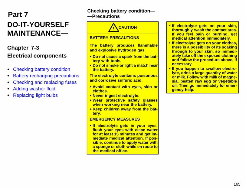
Part 7Checking battery condition——Precautions
165
DO-IT-YOURSELFMAINTENANCE—
Chapter 7-3Electrical components
� Checking battery condition� Battery recharging precautions� Checking and replacing fuses� Adding washer fluid� Replacing light bulbs
BATTERY PRECAUTIONS
The battery produces flammableand explosive hydrogen gas.
� Do not cause a spark from the bat-tery with tools.
� Do not smoke or light a match nearthe battery.
The electrolyte contains poisonousand corrosive sulfuric acid.
� Avoid contact with eyes, skin orclothes.
� Never ingest electrolyte.� Wear protective safety glasses
when working near the battery.� Keep children away from the bat-
tery.EMERGENCY MEASURES
� If electrolyte gets in your eyes,flush your eyes with clean waterfor at least 15 minutes and get im-mediate medical attention. If pos-sible, continue to apply water witha sponge or cloth while en route tothe medical office.
CAUTION!� If electrolyte gets on your skin,
thoroughly wash the contact area.If you feel pain or burning, getmedical attention immediately.
� If electrolyte gets on your clothes,there is a possibility of its soakingthrough to your skin, so immedi-ately take off the exposed clothingand follow the procedure above, ifnecessary.
� If you happen to swallow electro-lyte, drink a large quantity of wateror milk. Follow with milk of magne-sia, beaten raw egg or vegetableoil. Then go immediately for emer-gency help.

166
Check the battery for corroded orloose terminal connections, cracks, orloose hold-down clamp.a. If the battery is corroded, wash it offwith a solution of warm water and bakingsoda. Coat the outside of the terminalswith grease to prevent further corrosion.b. If the terminal connections are loose,tighten their clamp nuts—but do not over-tighten.c. Tighten the hold-down clamp onlyenough to keep the battery firmly in place.Overtightening may damage the batterycase.
NOTICE
�Be sure the engine and all acces-sories are off before performingmaintenance.
�When checking the battery, re-move the ground cable from thenegative terminal (“-” mark) firstand reinstall it last.
�Be careful not to cause a short cir-cuit with tools.
�Take care no solution gets into thebattery when washing it.
There are two types of batteries: main-tenance type and non-maintenancetype.A non-maintenance battery has “MAIN-TENANCE FREE BATTERY” on its top. Amaintenance type battery does not havesuch indication.Maintenance type battery—Check the fluid condition by the fluid levellines on the side of the battery. Or if thebattery has a hydrometer on its top, youcan also check the hydrometer.Non-maintenance battery—Check the battery condition by thehydrometer on the top of the battery.
—Checking battery exterior —Checking battery fluid
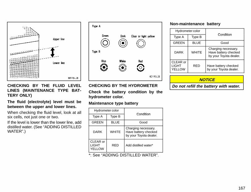
167
CHECKING BY THE FLUID LEVELLINES (MAINTENANCE TYPE BAT-TERY ONLY)
The fluid (electrolyte) level must bebetween the upper and lower lines.When checking the fluid level, look at allsix cells, not just one or two.If the level is lower than the lower line, adddistilled water. (See “ADDING DISTILLEDWATER”.)
CHECKING BY THE HYDROMETER
Check the battery condition by thehydrometer color.
Maintenance type battery
Hydrometer colorCondition
Type A Type BCondition
GREEN BLUE Good
DARK WHITECharging necessary.Have battery checkedby your Toyota dealer.
CLEAR orLIGHTYELLOW
RED Add distilled water*
*: See “ADDING DISTILLED WATER”.
Non-maintenance battery
Hydrometer colorCondition
Type A Type BCondition
GREEN BLUE Good
DARK WHITECharging necessary.Have battery checkedby your Toyota dealer.
CLEAR orLIGHTYELLOW
RED Have battery checkedby your Toyota dealer.
NOTICE
Do not refill the battery with water.
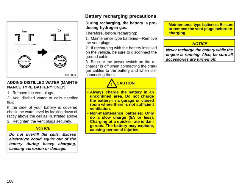
168
ADDING DISTILLED WATER (MAINTE-NANCE TYPE BATTERY ONLY)1. Remove the vent plugs.2. Add distilled water to cells needingfluid.If the side of your battery is covered,check the water level by looking down di-rectly above the cell as illustrated above.3. Retighten the vent plugs securely.
NOTICE
Do not overfill the cells. Excesselectrolyte could squirt out of thebattery during heavy charging,causing corrosion or damage.
During recharging, the battery is pro-ducing hydrogen gas.Therefore, before recharging:1. Maintenance type batteries—Removethe vent plugs.2. If recharging with the battery installedon the vehicle, be sure to disconnect theground cable.3. Be sure the power switch on the re-charger is off when connecting the char-ger cables to the battery and when dis-connecting them.
� Always charge the battery in anunconfined area. Do not chargethe battery in a garage or closedroom where there is not sufficientventilation.
� Non-maintenance batteries: Onlydo a slow charge (5A or less).Charging at a quicker rate is dan-gerous. The battery may explode,causing personal injuries.
CAUTION!
Maintenance type batteries: Be sureto remove the vent plugs before re-charging.
NOTICE
Never recharge the battery while theengine is running. Also, be sure allaccessories are turned off.
Battery recharging precautions
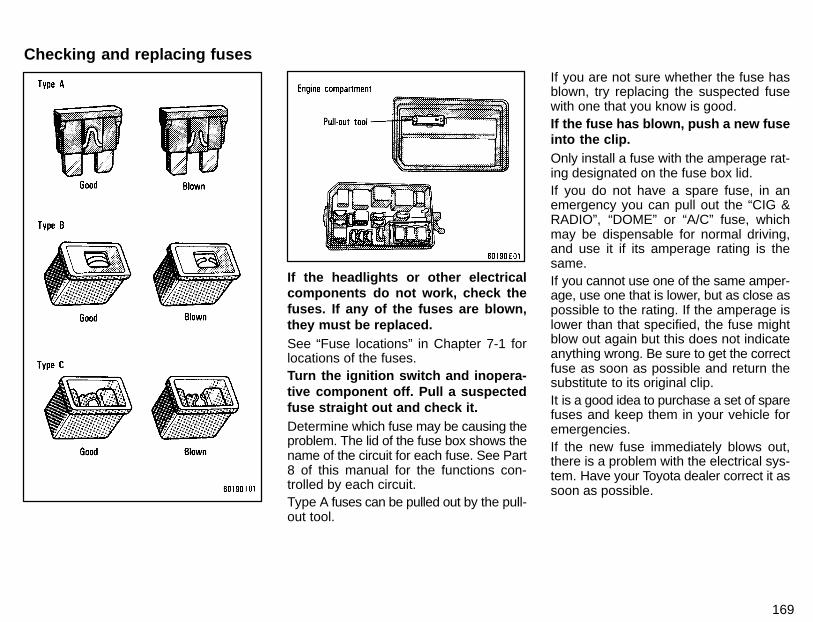
169
If the headlights or other electricalcomponents do not work, check thefuses. If any of the fuses are blown,they must be replaced.See “Fuse locations” in Chapter 7-1 forlocations of the fuses.Turn the ignition switch and inopera-tive component off. Pull a suspectedfuse straight out and check it.Determine which fuse may be causing theproblem. The lid of the fuse box shows thename of the circuit for each fuse. See Part8 of this manual for the functions con-trolled by each circuit.Type A fuses can be pulled out by the pull-out tool.
If you are not sure whether the fuse hasblown, try replacing the suspected fusewith one that you know is good.If the fuse has blown, push a new fuseinto the clip.Only install a fuse with the amperage rat-ing designated on the fuse box lid.If you do not have a spare fuse, in anemergency you can pull out the “CIG &RADIO”, “DOME” or “A/C” fuse, whichmay be dispensable for normal driving,and use it if its amperage rating is thesame.If you cannot use one of the same amper-age, use one that is lower, but as close aspossible to the rating. If the amperage islower than that specified, the fuse mightblow out again but this does not indicateanything wrong. Be sure to get the correctfuse as soon as possible and return thesubstitute to its original clip.It is a good idea to purchase a set of sparefuses and keep them in your vehicle foremergencies.If the new fuse immediately blows out,there is a problem with the electrical sys-tem. Have your Toyota dealer correct it assoon as possible.
Checking and replacing fuses
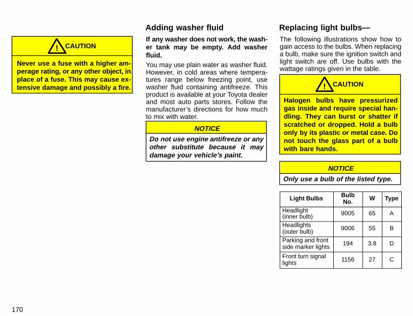
170
Never use a fuse with a higher am-perage rating, or any other object, inplace of a fuse. This may cause ex-tensive damage and possibly a fire.
CAUTION!If any washer does not work, the wash-er tank may be empty. Add washerfluid.You may use plain water as washer fluid.However, in cold areas where tempera-tures range below freezing point, usewasher fluid containing antifreeze. Thisproduct is available at your Toyota dealerand most auto parts stores. Follow themanufacturer’s directions for how muchto mix with water.
NOTICE
Do not use engine antifreeze or anyother substitute because it maydamage your vehicle’s paint.
The following illustrations show how togain access to the bulbs. When replacinga bulb, make sure the ignition switch andlight switch are off. Use bulbs with thewattage ratings given in the table.
Halogen bulbs have pressurizedgas inside and require special han-dling. They can burst or shatter ifscratched or dropped. Hold a bulbonly by its plastic or metal case. Donot touch the glass part of a bulbwith bare hands.
CAUTION!
NOTICE
Only use a bulb of the listed type.
Light Bulbs BulbNo. W Type
Headlight(inner bulb) 9005 65 A
Headlights(outer bulb) 9006 55 B
Parking and frontside marker lights 194 3.8 D
Front turn signallights 1156 27 C
Adding washer fluid Replacing light bulbs—
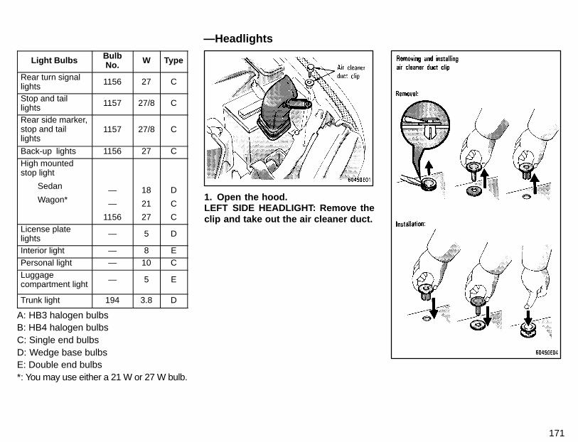
171
Light Bulbs BulbNo. W Type
Rear turn signallights 1156 27 C
Stop and taillights 1157 27/8 C
Rear side marker,stop and taillights
1157 27/8 C
Back-up lights 1156 27 CHigh mountedstop light
Sedan
Wagon*—
—
1156
18
21
27
D
C
CLicense platelights — 5 D
Interior light — 8 EPersonal light — 10 CLuggagecompartment light — 5 E
Trunk light 194 3.8 D
A: HB3 halogen bulbsB: HB4 halogen bulbsC: Single end bulbsD: Wedge base bulbsE: Double end bulbs*: You may use either a 21 W or 27 W bulb.
1. Open the hood.LEFT SIDE HEADLIGHT: Remove theclip and take out the air cleaner duct.
—Headlights
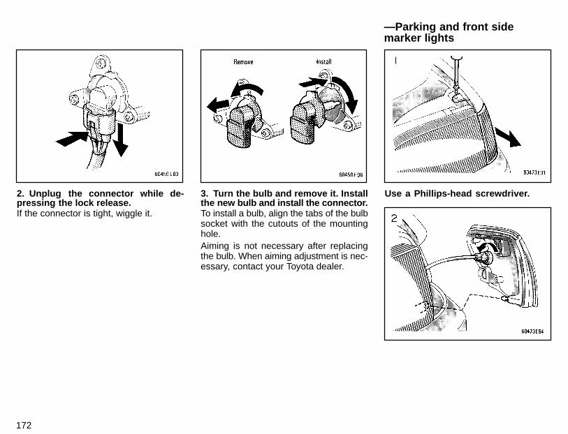
172
2. Unplug the connector while de-pressing the lock release.If the connector is tight, wiggle it.
3. Turn the bulb and remove it. Installthe new bulb and install the connector.To install a bulb, align the tabs of the bulbsocket with the cutouts of the mountinghole.Aiming is not necessary after replacingthe bulb. When aiming adjustment is nec-essary, contact your Toyota dealer.
Use a Phillips-head screwdriver.
—Parking and front sidemarker lights
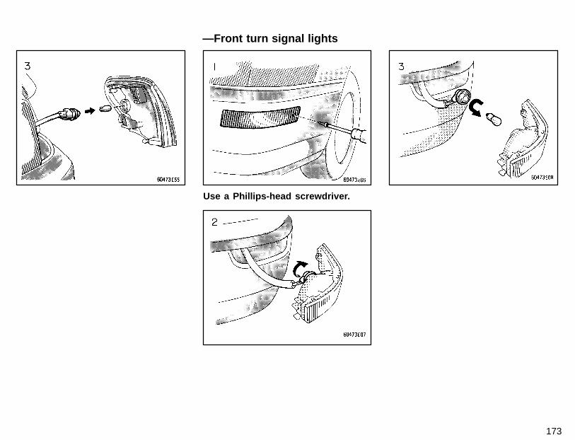
173
Use a Phillips-head screwdriver.
—Front turn signal lights
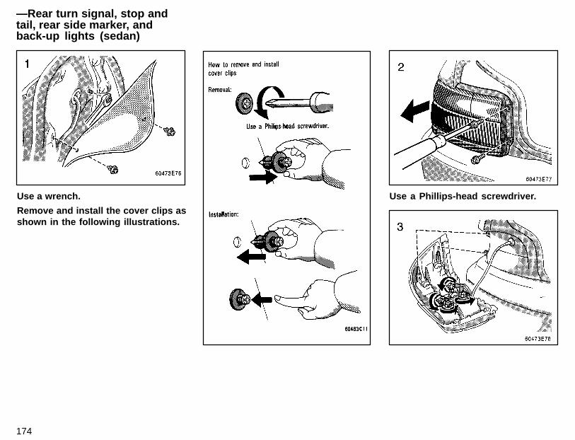
174
Use a wrench.
Remove and install the cover clips asshown in the following illustrations.
Use a Phillips-head screwdriver.
—Rear turn signal, stop andtail, rear side marker, andback-up lights (sedan)
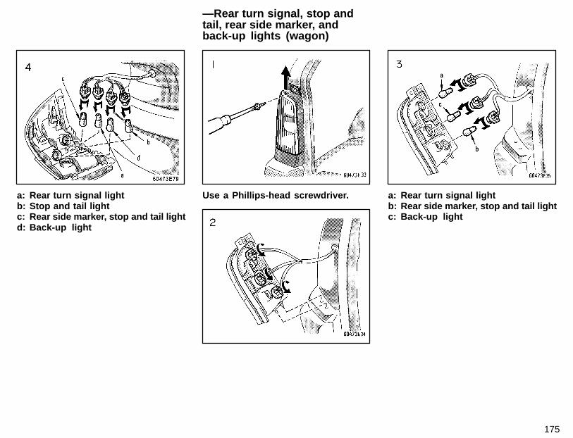
175
a: Rear turn signal lightb: Stop and tail lightc: Rear side marker, stop and tail lightd: Back-up light
Use a Phillips-head screwdriver. a: Rear turn signal lightb: Rear side marker, stop and tail lightc: Back-up light
—Rear turn signal, stop andtail, rear side marker, andback-up lights (wagon)
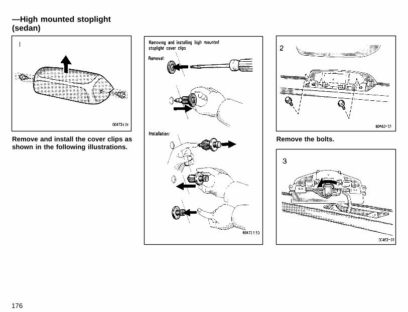
176
Remove and install the cover clips asshown in the following illustrations.
Remove the bolts.
—High mounted stoplight(sedan)
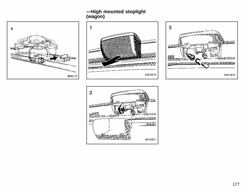
177
—High mounted stoplight(wagon)
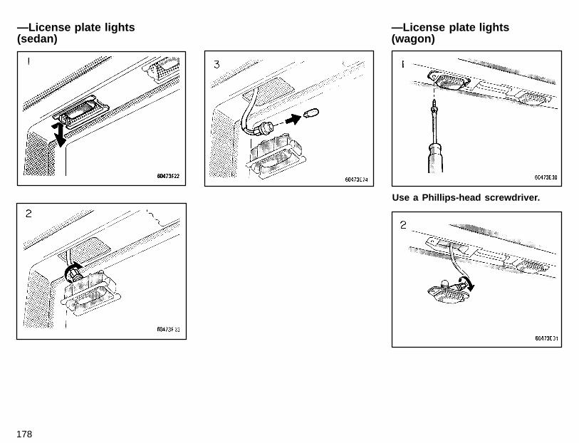
178
Use a Phillips-head screwdriver.
—License plate lights(wagon)
—License plate lights(sedan)
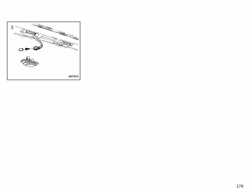
179

180
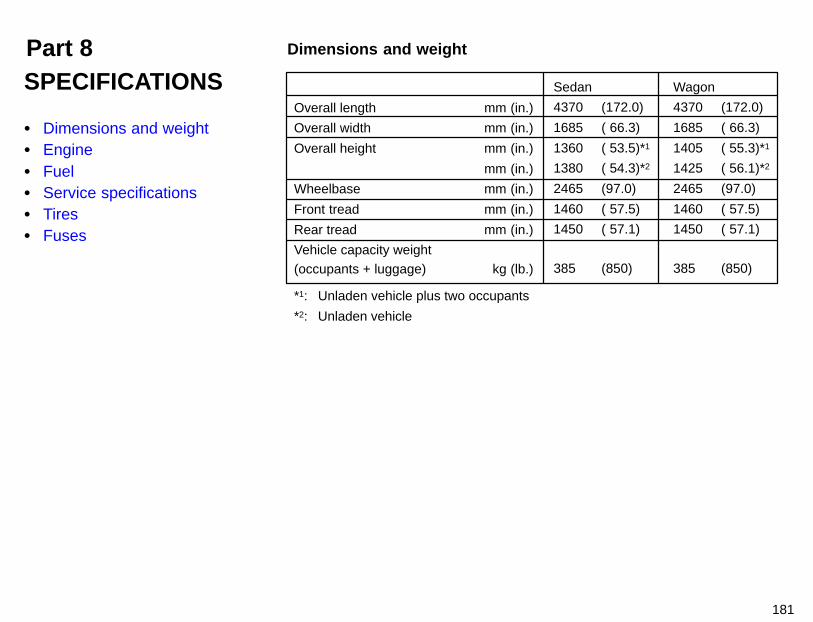
Part 8 Dimensions and weight
181
SPECIFICATIONS
� Dimensions and weight� Engine� Fuel� Service specifications� Tires� Fuses
Overall length mm (in.)
Overall width mm (in.)
Overall height mm (in.)
mm (in.)
Wheelbase mm (in.)
Front tread mm (in.)
Rear tread mm (in.)
Vehicle capacity weight(occupants + luggage) kg (lb.)
*1: Unladen vehicle plus two occupants
*2: Unladen vehicle
Sedan Wagon
4370 (172.0) 4370 (172.0)
1685 ( 66.3) 1685 ( 66.3)
1360 ( 53.5)*1 1405 ( 55.3)*1
1380 ( 54.3)*2 1425 ( 56.1)*2
2465 (97.0) 2465 (97.0)
1460 ( 57.5) 1460 ( 57.5)
1450 ( 57.1) 1450 ( 57.1)
385 (850) 385 (850)
182
Model:4A-FE and 7A-FE
Type:4 cylinder in line, 4 cycle, gasoline
Bore and stroke, mm (in.):4A-FE engine
81.0 x 77.0 (3.19 x 3.03)7A-FE engine
81.0 x 85.5 (3.19 x 3.37)Displacement, cm3 (cu. in.):
4A-FE engine 1587 (96.8)7A-FE engine 1762 (107.5)
Fuel type:Unleaded fuel, Research Octane Num-ber 91 (Octane Rating 87) or higher
Fuel tank capacity, L (gal., Imp. gal.):50 (13.2, 11.0)
ENGINEValve clearance (engine cold), mm (in.):
Intake 0.15 0.25 (0.006 0.010)Exhaust 0.25 0.35 (0.010 0.014)
Spark plug type:NIPPONDENSO K16R-UNGK BKR5EYA
Spark plug gap, mm (in.):0.8 (0.031)
Drive belt tension measured with Borroughsdrive belt tension gauge No. BT- 33- 73F(used belt), Ibf:
Generator belt 115 ± 20Air conditioning
compressor belt 100 ± 20Power steering
pump belt 80 ± 20ENGINE LUBRICATIONOil capacity (drain and refill), L (qt., Imp.qt.):
4A-FE engineWith filter 3.0 (3.2, 2.6)Without filter 2.8 (3.0, 2.5)
7A-FE engineWith filter 3.7 (3.9, 3.3)Without filter 3.5 (3.7, 3.1)
Fuel Service specificationsEngine
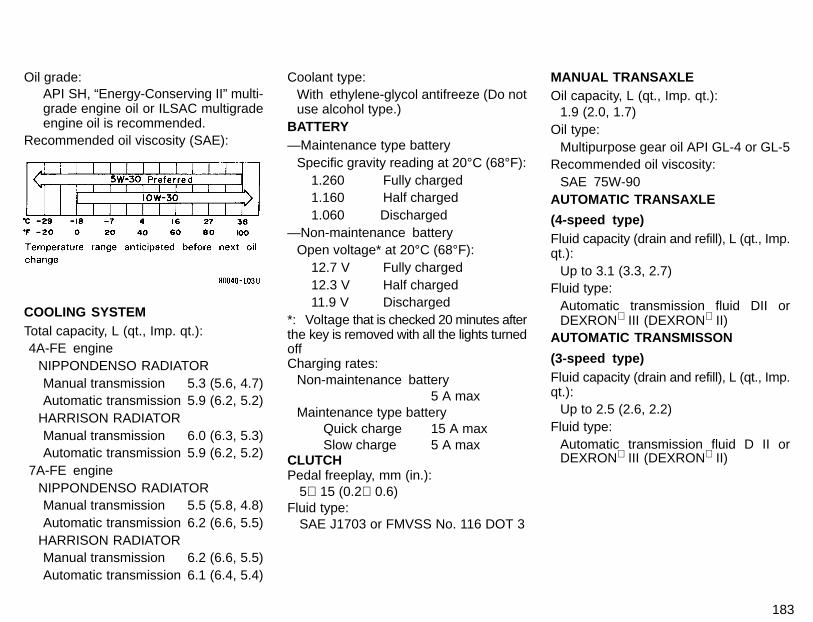
183
Oil grade:API SH, “Energy-Conserving II” multi-grade engine oil or ILSAC multigradeengine oil is recommended.
Recommended oil viscosity (SAE):
COOLING SYSTEMTotal capacity, L (qt., Imp. qt.):4A-FE engine
NIPPONDENSO RADIATORManual transmission 5.3 (5.6, 4.7)Automatic transmission 5.9 (6.2, 5.2)
HARRISON RADIATORManual transmission 6.0 (6.3, 5.3)Automatic transmission 5.9 (6.2, 5.2)
7A-FE engineNIPPONDENSO RADIATORManual transmission 5.5 (5.8, 4.8)Automatic transmission 6.2 (6.6, 5.5)
HARRISON RADIATORManual transmission 6.2 (6.6, 5.5)Automatic transmission 6.1 (6.4, 5.4)
Coolant type:With ethylene-glycol antifreeze (Do notuse alcohol type.)
BATTERY—Maintenance type battery
Specific gravity reading at 20°C (68°F):1.260 Fully charged1.160 Half charged1.060 Discharged
—Non-maintenance batteryOpen voltage* at 20°C (68°F):
12.7 V Fully charged12.3 V Half charged11.9 V Discharged
*: Voltage that is checked 20 minutes afterthe key is removed with all the lights turnedoffCharging rates:
Non-maintenance battery5 A max
Maintenance type batteryQuick charge 15 A maxSlow charge 5 A max
CLUTCHPedal freeplay, mm (in.):
5 15 (0.2 0.6)Fluid type:
SAE J1703 or FMVSS No. 116 DOT 3
MANUAL TRANSAXLEOil capacity, L (qt., Imp. qt.):
1.9 (2.0, 1.7)Oil type:
Multipurpose gear oil API GL-4 or GL-5Recommended oil viscosity:
SAE 75W-90AUTOMATIC TRANSAXLE
(4-speed type)Fluid capacity (drain and refill), L (qt., Imp.qt.):
Up to 3.1 (3.3, 2.7)Fluid type:
Automatic transmission fluid DII orDEXRON III (DEXRON II)
AUTOMATIC TRANSMISSON
(3-speed type)Fluid capacity (drain and refill), L (qt., Imp.qt.):
Up to 2.5 (2.6, 2.2)Fluid type:
Automatic transmission fluid D II orDEXRON III (DEXRON II)
184
DIFFERENTIAL(3- speed type automatic transmission)Fluid capacity, L (qt., Imp. qt.):
1.4 (1.5, 1.2)Fluid type:
Automatic transmission fluid DEX-RON II
BRAKESMinimum pedal clearance when de-pressed, with the pressure of 490 N (50 kgf,110 lbf) with the engine running, mm (in.):
70 (2.8)Pedal freeplay, mm (in.):
1—6 (0.04—0.24)Pad wear limit, mm (in.):
1.0 (0.04)Lining wear limit, mm (in.):
1.0 (0.04)Parking brake adjustment when pulledwith the force of 196 N (20 kgf, 44 lbf):
4—7 clicksFluid type:
SAE J1703 or FMVSS No. 116 DOT 3STEERINGWheel freeplay:
Less than 30 mm (1.2 in.)Power steering fluid type:
Automatic transmission fluid DEX-RON -II or-III
Tire size:Spare tire
T115/70D14T135/70D15175/65R14 82SP175/65R14 81S185/65R14 85S185/65R14 86SP185/65R14 85S
Except spare tire175/65R14 82SP175/65R14 81S185/65R14 85S185/65R14 86SP185/65R14 85S
Tire pressure, kPa (kgf/cm 2 or bar, psi):T115/70D14 420 (4.2, 60)T115/70D15 420 (4.2, 60)175/65R14 82S 210 (2.1, 30)P175/65R14 81S 210 (2.1, 30)185/65R14 85S 210 (2.1, 30)185/65R14 86S 210 (2.1, 30)P185/65R14 85S 210 (2.1, 30)
Wheel size:T115/70D14 14 x 4TT135/70D15 15 x 4TOther tires 14 x 5.5J
14 x 5.5JJWheel nut torque, N ⋅m (kgf ⋅m, ft ⋅lbf):
103 (10.5, 76)
Tires
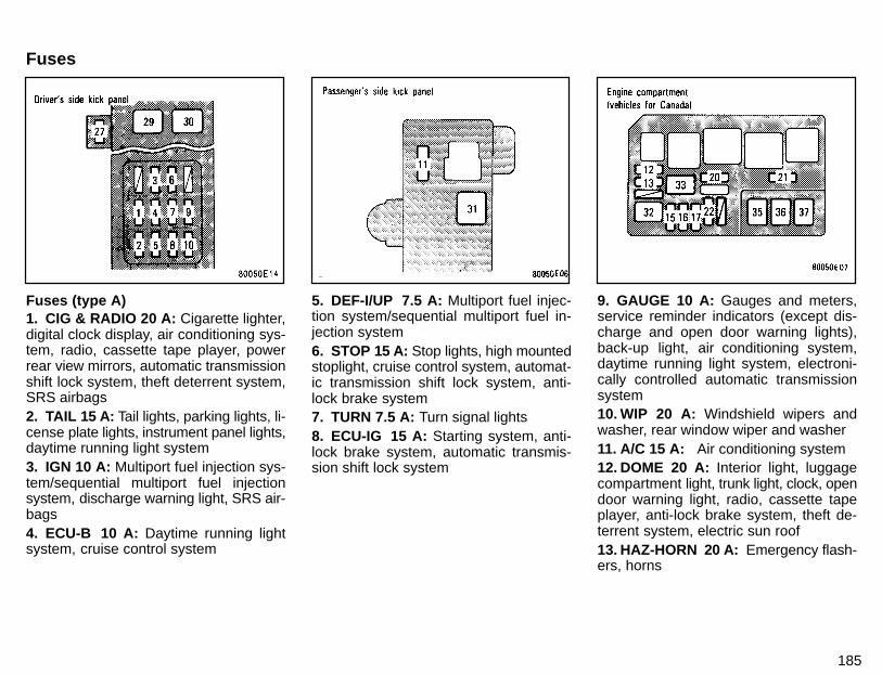
185
Fuses (type A)1. CIG & RADIO 20 A: Cigarette lighter,digital clock display, air conditioning sys-tem, radio, cassette tape player, powerrear view mirrors, automatic transmissionshift lock system, theft deterrent system,SRS airbags2. TAIL 15 A: Tail lights, parking lights, li-cense plate lights, instrument panel lights,daytime running light system3. IGN 10 A: Multiport fuel injection sys-tem/sequential multiport fuel injectionsystem, discharge warning light, SRS air-bags4. ECU-B 10 A: Daytime running lightsystem, cruise control system
5. DEF-I/UP 7.5 A: Multiport fuel injec-tion system/sequential multiport fuel in-jection system6. STOP 15 A: Stop lights, high mountedstoplight, cruise control system, automat-ic transmission shift lock system, anti-lock brake system7. TURN 7.5 A: Turn signal lights8. ECU-IG 15 A: Starting system, anti-lock brake system, automatic transmis-sion shift lock system
9. GAUGE 10 A: Gauges and meters,service reminder indicators (except dis-charge and open door warning lights),back-up light, air conditioning system,daytime running light system, electroni-cally controlled automatic transmissionsystem10. WIP 20 A: Windshield wipers andwasher, rear window wiper and washer11. A/C 15 A: Air conditioning system12. DOME 20 A: Interior light, luggagecompartment light, trunk light, clock, opendoor warning light, radio, cassette tapeplayer, anti-lock brake system, theft de-terrent system, electric sun roof13. HAZ-HORN 20 A: Emergency flash-ers, horns
Fuses
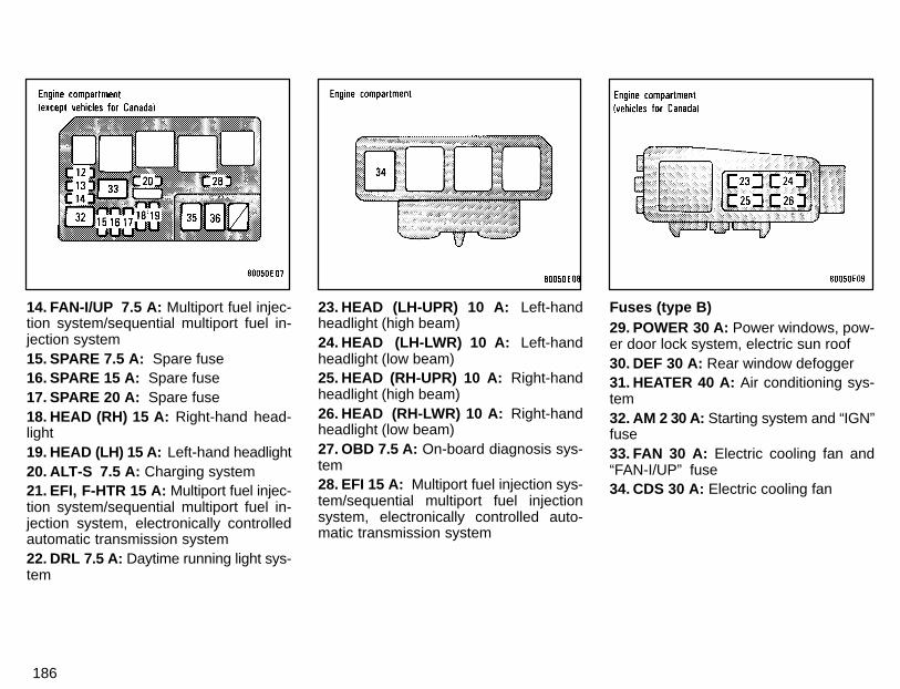
186
14. FAN-I/UP 7.5 A: Multiport fuel injec-tion system/sequential multiport fuel in-jection system15. SPARE 7.5 A: Spare fuse16. SPARE 15 A: Spare fuse17. SPARE 20 A: Spare fuse18. HEAD (RH) 15 A: Right-hand head-light19. HEAD (LH) 15 A: Left-hand headlight20. ALT-S 7.5 A: Charging system21. EFI, F-HTR 15 A: Multiport fuel injec-tion system/sequential multiport fuel in-jection system, electronically controlledautomatic transmission system22. DRL 7.5 A: Daytime running light sys-tem
23. HEAD (LH-UPR) 10 A: Left-handheadlight (high beam)24. HEAD (LH-LWR) 10 A: Left-handheadlight (low beam)25. HEAD (RH-UPR) 10 A: Right-handheadlight (high beam)26. HEAD (RH-LWR) 10 A: Right-handheadlight (low beam)27. OBD 7.5 A: On-board diagnosis sys-tem28. EFI 15 A: Multiport fuel injection sys-tem/sequential multiport fuel injectionsystem, electronically controlled auto-matic transmission system
Fuses (type B)29. POWER 30 A: Power windows, pow-er door lock system, electric sun roof30. DEF 30 A: Rear window defogger31. HEATER 40 A: Air conditioning sys-tem32. AM 2 30 A: Starting system and “IGN”fuse33. FAN 30 A: Electric cooling fan and“FAN-I/UP” fuse34. CDS 30 A: Electric cooling fan
187
Fuses (type C)35. AM1 40 A: “CIG & RADIO”, “GAUGE”,“TURN”, “ECU-IG”, “WIP”, “DEF” and“OBD” fuses36. ALT 100 A: Tail lights, “DEF”, “STOP”,“ECU-B” and “AM 1” fuses37. ABS 50 A: Anti-lock brake system

188
Part 9Reporting safety defects forU.S. owners Uniform tire quality grading
189
REPORTING SAFETYDEFECTS FOR U.S.OWNERS ANDUNIFORM TIREQUALITY GRADING
� Reporting safety defects forU.S. owners
� Uniform tire quality grading
If you believe that your vehicle hasa defect which could cause a crashor could cause injury or death, youshould immediately inform the Na-tional Highway Traffic Safety Admin-istration (NHTSA) in addition to noti-fying Toyota Motor Sales, U.S.A., Inc.(Toll-free: 1-800-331-4331).If NHTSA receives similar com-plaints, it may open an investigation,and if it finds that a safety defect ex-ists in a group of vehicles, it may or-der a recall and remedy campaign.However, NHTSA cannot become in-volved in individual problems be-tween you, your dealer, or ToyotaMotor Sales, U.S.A., Inc.To contact NHTSA, you may eithercall the Auto Safety Hotline toll-freeat 1-800-424-9393 (or 366-0123in Washington D.C. area) or writeto: NHTSA. U.S. Department ofTransportation. Washington D.C.20590. You can also obtain other in-formation about motor vehicle safe-ty from the Hotline.
This consumer information has been pre-pared in accordance with regulations is-sued by the National Highway TrafficSafety Administration of the U.S. Depart-ment of Transportation. It provides thepurchasers and/or prospective purchas-ers of Toyota vehicles with information onuniform tire quality grading.Your Toyota dealer will help answer anyquestions you may have as you read thisinformation.DOT quality grades—All passengervehicle tires must conform to FederalSafety Requirements in addition tothese grades. These quality grades aremolded on the sidewall.Treadwear —The treadwear grade is acomparative rating based on the wearrate of the tire when tested under con-trolled conditions on a specified govern-ment test course. For example, a tiregraded 150 would wear one and a half(1-1/2) times as well on the governmentcourse as a tire graded 100. The relativeperformance of tires depends upon theactual conditions of their use, however,and may depart significantly from thenorm due to variations in driving habits,service practices and differences in roadcharacteristics and climate.
190
Traction A, B, C— The traction grades,from highest to lowest, are A, B, and C,and they represent the tire’s ability to stopon wet pavement as measured undercontrolled conditions on specified govern-ment test surfaces of asphalt and con-crete. A tire marked C may have poor trac-tion performance.Warning: The traction grade assigned tothis tire is based on braking (straightahead) traction tests and does not includecornering (turning) traction.Temperature A, B, C— The temperaturegrades are A (the highest), B, and C, rep-resenting the tire’s resistance to the gen-eration of heat and its ability to dissipateheat when tested under controlled condi-tions on a specified indoor laboratory testwheel. Sustained high temperature cancause the material of the tire to degener-ate and reduce tire life, and excessivetemperature can lead to sudden tire fail-ure. The grade C corresponds to a level ofperformance which all passenger car tiresmust meet under the Federal Motor Ve-hicle Safety Standard No. 109. Grades Band A represent higher levels of perfor-mance on the laboratory test wheel thanthe minimum required by law.
Warning: The temperature grade for thistire is established for a tire that is properlyinflated and not overloaded. Excessivespeed, underinflation, or excessive load-ing, either separately or in combination,can cause heat buildup and possible tirefailure.

![STANDOX TOYOTA 2010 [Kompatibilitätsmodus]info.pages.color.tc/Yellowpages/SX/TOYOTA/TOYOTA Colour Info.pdf · TOYOTA MODELS / MODELLE VIN / TYPENSCHILD 01 Corolla Corolla Fielder](https://img.pdfslide.us/doc/110x75/5b5543817f8b9a575f8de257/standox-toyota-2010-kompatibilitaetsmodusinfopagescolortcyellowpagessxtoyotatoyota.jpg)