Embed Size (px)
Citation preview

Town of High River General Engineering and Construction Specifications
2017

CONTACT INFORMATION
GENERAL CONTACT INFORMATION Town of High River – Engineering 403-652-2110 Town of High River – Planning 403-652-2110 Town of High River – Operations 403-652-4657 Town of High River – Fire Department 403-652-3774 Town of High River – Bylaw Services 403-601-8696 RCMP (Non-Emergency) 403-652-2357
FIELD LOCATION SERVICES Alberta One Call 1-800-242-3447 ATCO Gas 403-652-2160 Town of High River – Operations 403-652-4657 Shaw Cable 403-716-6060 Fortis Alberta 403-310-9473
EMERGENCY ONLY Alberta One Call 1-800-242-3447 Town of High River – Roads 403-601-1258 Town of High River – Utilities 403-652-6353 Telus 611 ATCO Gas 1-800-511-3447 RCMP (Emergency Only) 911 Fire 911 Ambulance 911 Town of High River - Emergency Management (Only Activated in an Emergency)
403-652-6960
i
^ 3098 Macleod Trail SW0 ik _ High River, Alberra CanadaTlV 125
High'<1 RiverJune 15, 2017
Dear Sir/Madam:
P: 403.652.21 10 F: 403.652.2396
www.highriver.ca
The 2017 Town of High River General Engineering and Construction Specifications are foundto be acceptable in accordance with council policy POL-22-102-00. Should you have anycomments or suggestions while reading or using this document, I encourage you to submityour feedback to help further improve the document for both the Town and the end users.
Sincerely,
Reiley McKerracher, P. Eng.Director of Engineering, Planning, & Operations
TABLE OF CONTENTS Contact Information ........................................................................................................................ i
General Contact Information ...................................................................................................... i Field Location Services ............................................................................................................... i Emergency Only ........................................................................................................................... i
1 General ................................................................................................................................... 1
Specifications Used in the Town of High River .............................................................. 1 1.1 Municipal Engineer ......................................................................................................... 2 1.2 Engineer of Record .......................................................................................................... 2 1.3 Non-Standard Designs .................................................................................................... 2 1.4 Engineering and Landscaping Submissions .................................................................. 2 1.5
1.5.1 Hard Copy Drawing Submissions ............................................................................ 2
1.5.2 Digital Drawing Submissions ................................................................................... 3
1.5.3 Construction Completion Certificates (CCCs) ......................................................... 3
1.5.4 Final Acceptance Certificates (FACs) ...................................................................... 3
1.5.5 Development Completion Certificate (DCC) ........................................................... 4
1.5.6 Supporting Documentation ..................................................................................... 4
1.5.7 Video of Sewer Mains .............................................................................................. 4
Preliminary Engineering .................................................................................................. 4 1.61.6.1 Infrastructure Facilities ............................................................................................ 4
Special Design/Construction Considerations ............................................................... 4 1.71.7.1 Startup Notice .......................................................................................................... 4
1.7.2 Construction Supervision ........................................................................................ 4
1.7.3 Trenching .................................................................................................................. 5
1.7.4 Line Assignments ..................................................................................................... 5
Engineering Testing and Inspections ............................................................................. 5 1.81.8.1 Service Connection and Ditch Inspections ............................................................. 5
1.8.2 Meter Inspections .................................................................................................... 5
Lighting Design ................................................................................................................ 6 1.91.9.1 Public Roadways ...................................................................................................... 6
1.9.2 Private Developments.............................................................................................. 6
1.9.3 Pathways .................................................................................................................. 6
1.9.4 Town Owned Fixtures ............................................................................................... 6
2 Water Distribution Network ................................................................................................... 6
iii
Valves ............................................................................................................................... 6 2.1 Water Services and Meters ............................................................................................ 6 2.2 Hydrants ........................................................................................................................... 7 2.3 Water Main Sizing ........................................................................................................... 8 2.4 Fire Flow ........................................................................................................................... 8 2.5 PRV and Distribution Main Metering Vaults .................................................................. 9 2.6 Water Manholes .............................................................................................................. 9 2.7 Termination ...................................................................................................................... 9 2.8
3 Sewer Collection System ..................................................................................................... 10
Services .......................................................................................................................... 10 3.1 Sewer Manholes ............................................................................................................ 10 3.2 Sanitary Forcemains ..................................................................................................... 10 3.3 Storm Water Treatment ................................................................................................ 10 3.4 Catch Basins .................................................................................................................. 11 3.5
4 Roads .................................................................................................................................... 11
Traffic Signals ................................................................................................................ 11 4.1 Traffic Accommodation Strategies for Construction ................................................... 12 4.2 Concrete Work ............................................................................................................... 12 4.3
4.3.1 Sidewalks................................................................................................................ 12
Traffic Calming ............................................................................................................... 12 4.44.4.1 Pinch Points ............................................................................................................ 12
Lanes .............................................................................................................................. 13 4.5 Road Surface Painting .................................................................................................. 13 4.6 Crosswalks ..................................................................................................................... 13 4.7 Top Lift Paving ............................................................................................................... 13 4.8
5 Pumping Facilities ................................................................................................................ 13
Controls .......................................................................................................................... 13 5.1 Buildings and Structures .............................................................................................. 14 5.2 Pumps and Motors ........................................................................................................ 14 5.3 Communications and Programming ............................................................................ 14 5.4 Lift Station Specific Requirements .............................................................................. 14 5.5
6 Shallow Utilities .................................................................................................................... 15
7 Landscaping ......................................................................................................................... 15
Design Considerations .................................................................................................. 15 7.1
iv
Pathways ........................................................................................................................ 15 7.2 Topsoil ............................................................................................................................ 16 7.3 Vegetation ...................................................................................................................... 16 7.4 Irrigation Systems .......................................................................................................... 17 7.5 Doggie Bag Stations ...................................................................................................... 18 7.6 Garbage Containers ...................................................................................................... 18 7.7 Benches ......................................................................................................................... 18 7.8 Lot Grading Tolerance ................................................................................................... 18 7.9
Medians and Boulevards .......................................................................................... 19 7.108 List of Sheets ........................................................................................................................ 19
Sheet 5 – Approved Tree List ...................................................................................................... 24
Sheet 6 – Native Tree Species List ............................................................................................. 26
v

1 GENERAL
SPECIFICATIONS USED IN THE TOWN OF HIGH RIVER 1.1Unless otherwise specified within this document, a Town of High River Bylaw (including, the Land Use Bylaw), or a Town policy or procedure, The Town of High River follows the following City of Calgary specifications: City of Calgary – Design Guidelines for Subdivision Servicing (2014) City of Calgary – Complete Streets Guide (2014) City of Calgary – Design Guidelines for Development Site Servicing Plans (DSSP) (2015) City of Calgary – Temporary Traffic Control Manual (2016) City of Calgary – Stormwater Management and Design Manual (2011) City of Calgary – Development Guidelines and Standard Specifications: Landscape Construction (2017) City of Calgary – Standard Specifications: Roads Construction (2015) City of Calgary – Standard Specifications: Sewer Construction (2016) City of Calgary – Standard Specifications: Water Construction (2016) City of Calgary – Environmental Construction Operations (ECO) Plan Framework (2014) City of Calgary – Field Manual for Erosion and Sediment Control (2011) City of Calgary – Guidelines for Erosion and Sediment Control (2011) City of Calgary – Consulting Engineer’s Field Services Guidelines (2012) Good engineering practices should be adhered to at all times. The Municipal Engineer reserves the right to: approve alternate standards, approve exceptions on any submissions, or require that a higher standard be met. The Municipal Engineer may modify or update the General Engineering and Construction Specifications in accordance with Policy POL-22-102-00. When questions regarding road design arise, the Town commonly refers to publications by the Transportation Association of Canada (TAC) Recommendations made by the Town of High River’s 2015 Infrastructure Master Plan (Phase 1 update) shall be followed whenever possible. The Infrastructure Master Plan is available on the Town of High River website or by request from the Town of High River’s engineering department in pdf format only. Flood mitigation shall be in accordance with the Land Use Bylaw (4510/2017). Elevations and locations are governed by the Land Use Bylaw. Mitigation design should be strongly influenced by the following documents: Government of British Columbia - Dike Design and Construction Guide – Best Management Practices (2011) Government of British Columbia – Riprap Design and Construction Guide (2000) Government of Alberta – Field Guide for Erosion and Sediment Control (2011) Canadian Dam Association – Dam Safety Guidelines (2007) US Army Corps of Engineers – Design and Construction of Levees (2000)
1

MUNICIPAL ENGINEER 1.2The Municipal Engineer shall mean the Director of Engineering, Planning, and Operational Services or his/her designate. The Municipal Engineer is responsible for approval of non-standard designs and design exceptions.
ENGINEER OF RECORD 1.3The Engineer of Record is the authorized point of contact between the Developer and the Town of High River. The Engineer of Record must be a Professional Engineer, registered with APEGA, or a P. Tech. (eng) registered with ASET, and authorized to practice engineering within the province of Alberta. A Developer must have an Engineer of Record at all times during Development. In the case the Engineer of Record no longer represents the developer, the Developer and/or Engineering of Record must notify the Town within 5 business days’. Work may not proceed until another Engineer of Record is appointed. For construction supervision or engineering test and inspections, the Engineer of Record may designate a representative to act on their behalf and must be a P. Eng. or C.E.T.
NON-STANDARD DESIGNS 1.4The Town encourages the use of non-standard and innovative design practices that help the Town meet Council’s vision, the goals of the High River Town Plan and High River Growth Management Strategy, mitigate flooding concerns, provide a higher standard than required, or achieve a greater level of conservation and sustainability than what would normally be reached. All non-standard designs are subject to approval by the Municipal Engineer.
ENGINEERING AND LANDSCAPING SUBMISSIONS 1.5Note the following requirements for engineering submissions. Incomplete submissions can be rejected and returned at the discretion of the Town. All submissions must include both hard copy and digital submissions.
• For Developments, in addition to the standard engineering and landscaping drawings required in a submission (outlined in City of Calgary - Design Guidelines for Development Permits and City of Calgary - Landscape Construction, respectively), a photometric grid drawing is required.
• Engineering drawings shall be stamped with a valid APEGA permit to practice and by a registered Alberta Professional Engineer
• Landscaping drawings shall be stamped by a Landscape Architect registered with the AALA
• No stamping professional is required on photometric grid drawings
1.5.1 Hard Copy Drawing Submissions
All hard copy engineering and landscaping drawing submissions to the Town of High River shall consist of the following:
• 2 full sets of 24”x36” paper drawings for review submissions plus digital submission
2

• 1 full set of 24”x36” paper drawings for as-built submissions plus digital submission
1.5.2 Digital Drawing Submissions
Digital drawings must be submitted with all hard copy submissions in both AutoCAD and PDF formats (and GIS formats for as-builts). Drawing requirements include:
• AutoCAD drawings must be submitted in 2004 or newer version • All relevant information necessary to recreate the PDF shall be included in the
AutoCAD submission • Any objects or text within the submission must be located in model space, using
NAD83 3TM projection, central meridian 114 with no scaling, rotating, or shifting required
• Submission must be purged of all definitions that are not used such as layers, layer filters, text styles, dimension styles, blocks, etc.
• Duplicate objects and text are to be removed • All objects must be on the correct layer • Layers must be clearly labeled, with a legend that defines what is on each layer • Line work relevant to the current submission must be clearly labeled as such, and
any existing or future information not pertaining to the development must also be clearly labeled or removed
• In addition to AutoCAD and PDF, as-builts require a GIS submission such as shape files or .gdb
1.5.3 Construction Completion Certificates (CCCs)
After the completion of construction, the Engineer of Record may apply for CCCs for the local improvements. CCC submissions shall consist of the following documentation:
• Three originals of the Town of High River’s CCC form with attached letter sized plans highlighting the local improvements
• Test results including, but not limited to, compaction, concrete, and asphalt testing • Hydrant Certificates (including onsite hydrants) • Pressure test report • Bacteria testing results • Sewer video inspection and report • Structural design of the asphalt • Lot service cards • Note that mandrel testing is not required at time of CCC
1.5.4 Final Acceptance Certificates (FACs)
Following the required maintenance period(s), the Engineer of Record may apply for FACs for the local improvements. FAC submissions shall consist of the following documentation:
• Three originals of the Town of High River’s FAC form with attached letter sized plans highlighting the local improvements
• As-built drawing submission • Test results for repair work
3
• Certification of CCC repair work • A second sewer video inspection and report • Mandrel test results
1.5.5 Development Completion Certificate (DCC)
For private sites, the Engineer of Record may apply for DCC after the issuance of all FACs. DCC submissions shall consist of the following documentation:
• Three originals of the Town of High River’s DCC form with attached letter sized plans highlighting the completed Development
• As-built drawing submission • Hydrant Certificates (not required if submitted at CCC) • Test results including, but not limited to, compaction, concrete, and asphalt testing • Bacterial testing results • Sewer video inspection and report
1.5.6 Supporting Documentation
Supporting documentation outlining warranty periods, and CCC/FAC/DCC forms can be found in the Development Agreement or the Subdivision Agreement.
1.5.7 Video of Sewer Mains
All sewer video inspections shall be executed in accordance with CSA Plus 4012 – Visual Sewer Inspection Technical Guide as well as follow NASSCO requirements. CCC videoing shall occur no sooner than 14 days after complete backfill. FAC and DCC videoing shall occur no sooner than 2 full winters after complete backfill.
PRELIMINARY ENGINEERING 1.6
1.6.1 Infrastructure Facilities
A pre-design brief/report is required on all infrastructure facilities including, but not limited to, storm ponds, booster stations, and lift stations.
SPECIAL DESIGN/CONSTRUCTION CONSIDERATIONS 1.7
1.7.1 Startup Notice
The Town shall be given written notice a minimum of 5 business days’ prior to the start of any Development, Subdivision, or construction unless otherwise stated in the Development/Subdivision Agreement or contract.
1.7.2 Construction Supervision
All work for a Development or Subdivision taking place within an existing Town right-of-way shall have full time supervision provided by the Engineer of Record.
4

1.7.3 Trenching
All trenching shall have clay plugs installed a maximum distance of 200 meters apart, and at the upstream end of each valve or pipe intersection.
1.7.4 Line Assignments
The line assignments for deep utilities will be as follows: Utility Location within Right-of-Way Sanitary Sewer Centre Storm Sewer East/South Watermain West/North
ENGINEERING TESTING AND INSPECTIONS 1.8Contact the Town Engineering or Operations Department (as indicated) a minimum of 2 business days’ in advance to arrange for inspections. The inspections/tests that require the presence of both the Town and the Engineer of Record include, but are not limited to: Engineering Operations • CCC/FAC/DCC Inspections • Service Connection Inspections (single
family and duplex services) • Service Connection Inspection • Service Ditch Inspections • Meter Inspections • Pressure and Leakage Testing • Roll Tests for Road, Road Base, and
Concrete
• Mandrel Testing • Bacteria Testing These inspections are for all improvements as shown on the approved engineering drawings including those shown on private property.
1.8.1 Service Connection and Ditch Inspections
Prior to backfill and having a water service turned on, a service connection/ditch inspection is required. Should the inspection fail, re-inspection is required after the necessary corrections are made prior to the service being turned on.
1.8.2 Meter Inspections
Prior to having a service turned on, a meter inspection is required. Should the inspection fail, re-inspection is required after the necessary corrections are made prior to the service being turned on. Furthermore, a meter tree inspection will be performed with the Certificate of Site Use inspection if a meter tree detail was required on the engineering drawings. See the Development Agreement for full details of the Certificate of Site Use.
5

LIGHTING DESIGN 1.9Unless otherwise approved by the Town, all lighting standards shall be zero cut off (i.e. flat lens) and shall be LED.
1.9.1 Public Roadways
Lighting design for public roadways shall be in accordance with IES standards and will be reviewed/approved by FortisAlberta. All fixtures shall be Fortis approved; non-standard fixtures will not be permitted.
1.9.2 Private Developments
Private Developments shall be lit to the following standards:
Area Minimum (lux/fc) Maximum (lux/fc) Parking 5.0/0.5 22/2.0 Pedestrian Areas 5.0/0.5 11/1.0 Lighting grids on submitted lighting plans shall extend a minimum of 8m beyond the property line. Lighting levels 8m outside the property shall not exceed 5.0 lux (0.5 fc).
1.9.3 Pathways
Where lighting is required, levels shall be consistent with pedestrian areas in section 1.9.2 and shall be FortisAlberta approved fixtures.
1.9.4 Town Owned Fixtures
For all fixtures to be owned by the Town, the Developer shall make arrangements to have all street lighting installed under the 31 rate code. The Lighting Investment provided by FortisAlberta will be paid to the Town of High River.
2 WATER DISTRIBUTION NETWORK
VALVES 2.1The Municipal Engineer may request additional valves than those required by City of Calgary specifications for increased reliability of service. Valves in the Town differ from City of Calgary in that all valves shall turn counter-clockwise (left) to open unless otherwise specified. All valves in road right-of-ways are required to be Type C deep lids.
WATER SERVICES AND METERS 2.2• All services shall be PEX or PVC DR-18.
6

• All services shall remain dry and closed until such time they are connected to a water meter.
• All services shall have a water meter installed. • Meter horns are not permitted. • The Developer is responsible to remove all unused and abandoned service
connections resulting from the Development. The services must be completely removed from the main and repaired by an approved method.
• Row housing fronting a public road shall have a separate service and meter for each unit. Each service shall have its own curb stop.
• Apartment style housing shall have a single service with a single water meter. A main valve is required for each service.
• Bank metering for residential (row housing or apartment style) will be considered, requiring approval from the Municipal Engineer. An externally accessible metering room is required.
• In situations where there are multiple connections to a private main (i.e. with row housing, trailer parks, multiple apartment buildings, or commercial CRUs) the Town may require a meter vault at property line.
• Commercial metering utilizing bank metering shall have a metering room. The room shall be accessible to the Town. To provide access a key vault with a key shall be placed on the door. The Town will provide the code for the key vault.
• The preferred key vault is a GE Key Safe. Other mechanical (non-battery operated) door mounted vaults that accept 6 digit codes will be considered.
• Water meter vaults shall have a sump and pump, telecommunication service, and equipment as required by the Town.
• 5/8” and 1” water meters shall be Badger E-Series Ultrasonic polymer water meter and pit model 3-port Itron 100W+ ERT in cubic meters. Water meters 1.5” or larger shall be Badger stainless steel E-Series Ultrasonic water meter and pit model 3-port Itron 100W+ ERT in cubic meters. All meters are to be supplied by the Town. Contact the Operations Department to purchase a meter.
• Installation of the water meter is the responsibility of the Property Owner or Developer and must be inspected by the Town Operations Department.
• Any water service with a joint between the curb stop/service valve on the street and the meter requires a pressure test which shall be witnessed by the Town.
• When designing a meter tree, refer to the Town’s current Water Systems Bylaw.
HYDRANTS 2.3All hydrants shall be Mueller Centurion or approved equivalent and conform to the following:
• Hose nozzle (AMA) Alberta Mutual Aid, • Size 6.35cm (2.5”) inside diameter – 8 threads per inch, • Fitted with a 4” Stortz connection, • All threads of discharge ports must be lubricated/lightly greased using food grade
grease only, • A break off flange above, but no more than 0.3m above, the ground line,
7
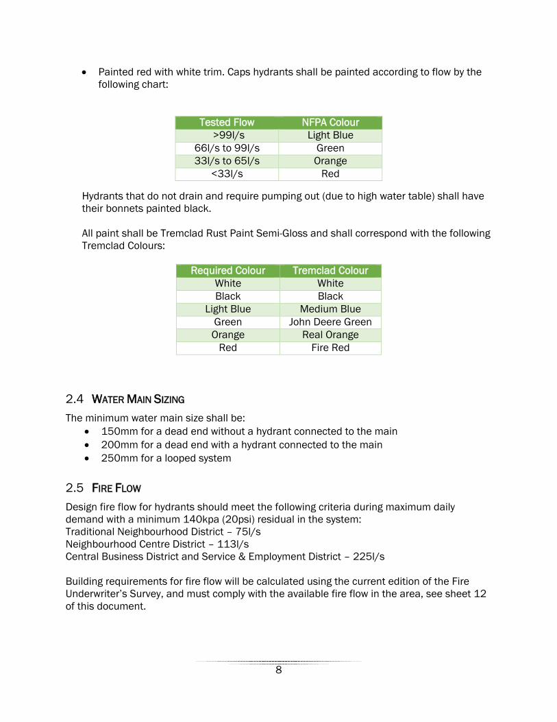
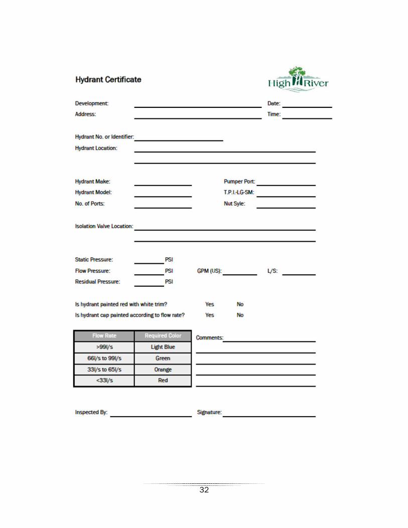
• Painted red with white trim. Caps hydrants shall be painted according to flow by the following chart:
Hydrants that do not drain and require pumping out (due to high water table) shall have their bonnets painted black. All paint shall be Tremclad Rust Paint Semi-Gloss and shall correspond with the following Tremclad Colours:
WATER MAIN SIZING 2.4The minimum water main size shall be:
• 150mm for a dead end without a hydrant connected to the main • 200mm for a dead end with a hydrant connected to the main • 250mm for a looped system
FIRE FLOW 2.5Design fire flow for hydrants should meet the following criteria during maximum daily demand with a minimum 140kpa (20psi) residual in the system: Traditional Neighbourhood District – 75l/s Neighbourhood Centre District – 113l/s Central Business District and Service & Employment District – 225l/s Building requirements for fire flow will be calculated using the current edition of the Fire Underwriter’s Survey, and must comply with the available fire flow in the area, see sheet 12 of this document.
Tested Flow NFPA Colour >99l/s Light Blue
66l/s to 99l/s Green 33l/s to 65l/s Orange
<33l/s Red
Required Colour Tremclad Colour White White Black Black
Light Blue Medium Blue Green John Deere Green Orange Real Orange
Red Fire Red
8
PRV AND DISTRIBUTION MAIN METERING VAULTS 2.6Vaults have the following requirements:
• A water sensor which shall be programmed to alarm out if the vault has more than 150mm of water accumulated in it.
• Pressure sensors, for a PRV, two are required (one upstream and one downstream) and for a meter, a single pressure sensor on the intake side is required.
• Vaults shall have communication as per Section 5, Pumping Facilities connected to all sensors in the vaults. All required programming to integrate the new vault into the Town’s systems shall be performed by the Town’s SCADA preferred contractor at the Developer’s cost.
• A drain connected to the sanitary main, should this not be a viable solution, a sump and pump connected to the sanitary sewer system shall be provided.
• All PRV vaults shall be metered. If a PRV vault is bi-directional, the meter needs provide totals for both directions. Metering shall be integrated into the Town’s SCADA system.
• A check valve is required for meter vaults. • All equipment shall be submersible. If submersible equipment cannot be provided,
additional measure must be taken to mitigate the risk of water damage to the equipment.
• All concrete joints forming the vault shall be sealed with Rub’r-Nek or an approved equivalent.
• All PRV and distribution main metering vaults require exterior seal wrapping on all joints, grade rings, and frames. These wraps shall be a minimum of 6” wide with 3” on either side of each joint.
WATER MANHOLES 2.7All manholes shall be watertight and sealed with Rub’r-Nek or an approved equivalent. All manhole lids shall be 24” in diameter and with a generic lid. Lids over flushing assemblies shall be lockable. All water manholes require exterior seal wrapping on all joints, grade rings, and frames. These wraps shall be a minimum of 6” wide with 3” on either side of each joint.
TERMINATION 2.8All terminations for tapped connections shall be performed with a stainless steel full wrap. Brass plugs will not be accepted.
9

3 SEWER COLLECTION SYSTEM
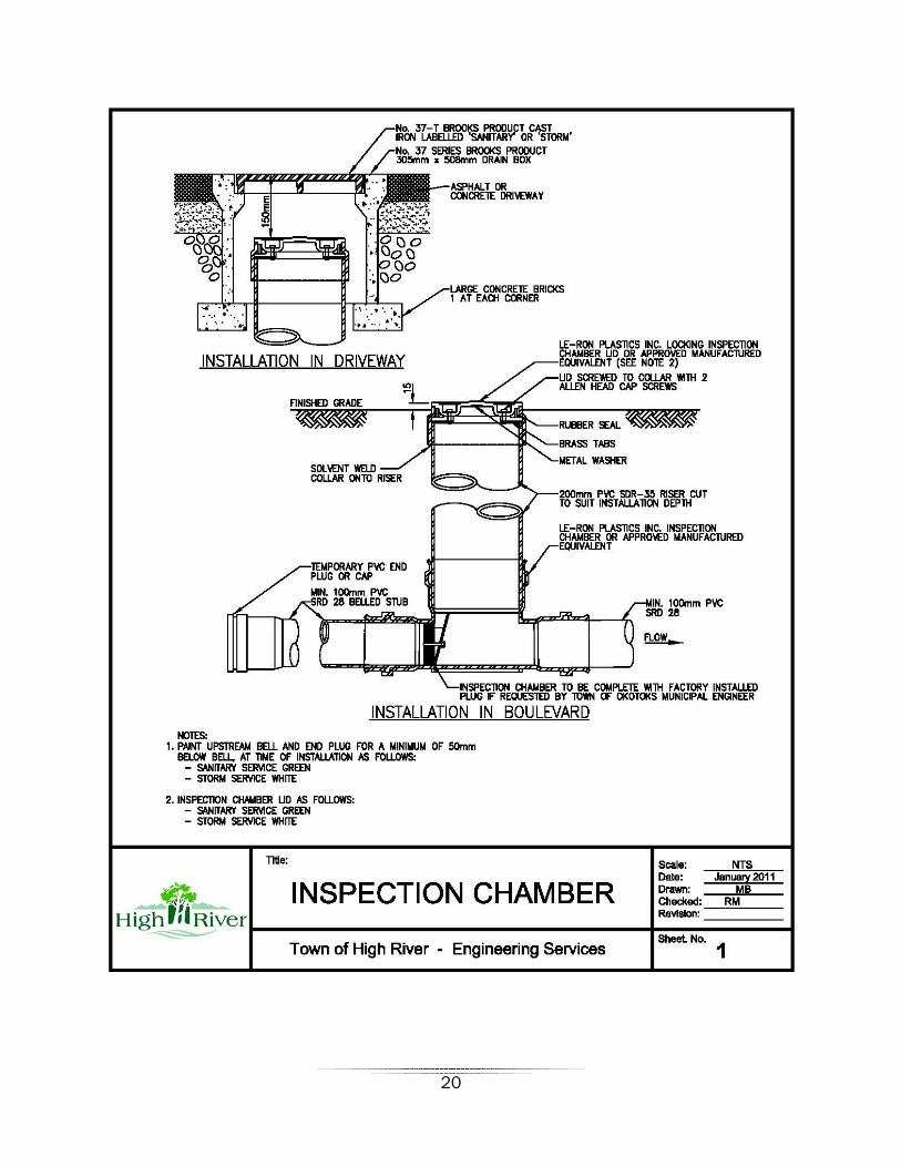
SERVICES 3.1All commercial and industrial sanitary services shall discharge through a test manhole or inspection chamber (shown on Sheet 1). For applications where there is a high sewage flow or high nutrient loading, a test manhole must be used rather than an inspection chamber.
SEWER MANHOLES 3.2• All manholes shall be minimum 1200mm 1 piece pre-benched manholes. • Manhole bases shall be pre-benched with bells and spigots. All manholes shall be
watertight and be sealed with Rub’r-Nek or an approved alternative. All manhole lids shall be 24” in diameter and have the Town logo and utility name on it as shown in Sheet 2. All sanitary manholes located in a trap low or with a rim elevation below the 1:100 flood elevation shall have silt bowls.
• All sewer manholes require exterior seal wrapping on all joints, grade rings, and frames. These wraps shall be a minimum of 6” wide with 3” on either side of each joint.
SANITARY FORCEMAINS 3.3Any new sanitary force main installed and not used to its design capacity immediately shall have an H2S suppression system installed, as approved by the Municipal Engineer. Examples of odor suppression measures are as follows:
• Air and oxygen injection – an air injector can be installed in the forcemain to inject minute air bubbles into the wastewater. The injected air will increase the dissolved oxygen in the wastewater to prevent H2S formation.
• Submersible aerators provide oxygen in the wet well, thereby hindering H2S formation. Aeration pumps require frequent maintenance due to debris within the wastewater.
• Pure oxygen may also be injected into the forcemain. The amount of oxygen injected will be less than the amount of air injected due to the relative concentration of oxygen, which will prevent H2S formation.
• Avoiding unnecessary mixing or agitation of the waterwater stream will lessen the chance of H2S off gassing. This can be achieved by not using vertical drops in manholes and wet wells.
STORM WATER TREATMENT 3.4Developments must not rely solely on storm ponds for treatment of storm water. Best Management Practices (BMPs), Low Impact Development techniques, and Source Control Practices (SCPs) shall be used. Sites that do not drain to a storm pond before releasing to the Highwood River or Little Bow Canal shall treat the majority of the storm water before releasing it.
10

Low cost maintenance should be a consideration of storm water treatment design.
CATCH BASINS 3.5Catch basins in vertical face curb shall have removable backs (see City of Calgary Sewer Construction Standard, Sheet 21A).
4 ROADS
TRAFFIC SIGNALS 4.1Traffic signals shall meet the following conditions:
• Econolite T2 double wide traffic cabinet (P44) with concrete base, • Dandy (or equivalent) power/metering cabinet with breaker box and concrete base, • All enclosures shall be NEMA 3R rated (or better). • Econolite Cobalt controller based system with Ethernet capabilities, • CSA approved poles and masts with engineering bases, • Autoscope TIP controller with Autoscope Encore cameras traffic detection system, • Emtrac emergency vehicle pre-emption compatible with the existing system, • No poles shall be located in medians, • Unless part of an overall lighting design, street lighting shall not be placed on the
traffic signal poles, • All traffic signals shall have 300mm tall street name signs placed on the masts, signs
shall be reflective blue with white lettering, • Signals shall be LED and have black backboards. There shall be a signal head for
each lane of traffic plus an additional head on the vertical traffic pole supporting the mast, the signal head for the furthest left lane of travel shall include a left turn arrow, regardless if it is to be activated or not,
• Communication/telemetry system as approved by the Town of High River. Where ever possible, fiber optics shall be used and shall utilize the following:
o Cisco IE 3000 series switches (IE-3000-8TC plus GLC-LX-SM-RGD fiber transceivers),
o 9/125 Single Mode fiber with minimum 12 cores/strands. If the fiber is to be used for a double run (i.e. in and out of a building) a minimum of 24 cores/strands is required. Fiber shall be placed in conduit with tracer wire.
o Termination of the fiber shall use standard ST connectors in exterior locations (i.e. traffic cabinets), and LC connectors in interior locations. A hard mounted termination panel is required where ever fiber is terminated. Connection to the fiber modules/modems from the termination panel shall be made with ST to LC patch cables.
o Fiber terminations shall leave a minimum of 1m of extra fiber on either end prior to termination. Extra fiber must be accommodated in the termination box or pedestal.
11
o All splicing shall take place in a cabinet or vault. Splice vaults that will be used for future splicing shall include 15m on each side of the splice. The splice itself shall be in a water tight enclosure. No splice may be direct buried.
• Where fiber is not feasible, point to point wireless may be used and shall utilize the following:
o All wireless communication devices will be provided by the Town at the Developer’s cost.
o The Developer is responsible for all costs associated with the installation and commissioning of Town supplied communication devices.
• Integration into the existing network is required with the installation of the traffic signals.
• All pedestals and cabinets shall have a base elevation (top of concrete) that is at or above the Minimum Development Elevation as defined in the Land Use Bylaw (4510/2017).
• A minimum 3.6 second yellow time and a minimum 2.0 second all red period between phases is to be used when programming signal timing.
TRAFFIC ACCOMMODATION STRATEGIES FOR CONSTRUCTION 4.2All traffic control shall be in accordance with the City of Calgary Temporary Traffic Control Manual. A Traffic accommodation strategy, including a drawing showing the proposed traffic control and written procedure, shall be submitted to the Town of High River a minimum of 5 business days’ prior to implementation. Drafts of public notices (if required) or extra measures that are to be taken in conjunction with the plan must be included with the submission. The Town of High River will be responsible for notifying affected parties. Approval is conditional pending comments from Engineering, Operations, Fire, and RCMP, etc.
CONCRETE WORK 4.3All concrete for road works, including but not limited to, sidewalks and curbs, shall be Class A, Type 50.
4.3.1 Sidewalks
Sidewalks shall have a granular base of 150mm pit run (75mm) and 50mm crush (30mm).
TRAFFIC CALMING 4.4Traffic calming is encouraged in all neighbourhoods.
4.4.1 Pinch Points
Pinch points shall have a width of 6.5m face of curb to face of curb. Pinch points shall be used at all midblock crossings as well as any other area where there is to be significant pedestrian/vehicle conflicts.
12

LANES 4.5All lanes shall be paved with the local road pavement structure (Council Resolution #385/2006).
ROAD SURFACE PAINTING 4.6All road paint shall contain glass beads. Crosswalks on roads designed as Collector Streets or better shall be thermoplastic (or equivalent). All crosswalks at midblock crossings shall be thermoplastic (or equivalent). Equivalents to thermoplastic crossings include, but are not limited to, concrete crossings. Thermoplastic lines shall be installed as required by the Town. All directional markings in road surface shall be thermoplastic. The Town accepts the following thermoplastic products:
• System 300 • System 400 • System 600 • ArcticLine HP Plastic Road Marking
System
• Poly Carb Mark 55.4 • Ennis Flint MMA Strip (Cold Plastic
Marking) • Sprayable Ennis Flint MMA Strip (Cold
Plastic Marking)
CROSSWALKS 4.7Crosswalks are to be provided and shown on design plans at all mid-block crossings and at high profile intersections as required by the Town. All required crosswalks shall be installed prior to applying for FAC. Crosswalks are to be painted in the Abby Road style, also referred to as Zebra style. See the TAC – Pedestrian Crossing Control Guide (December 2012) for full details. As a minimum, crosswalks shall be installed in the following locations:
• All mid-block crossings, • All crossings on roads classified as collector or higher, • As otherwise deemed appropriate by the Municipal Engineer.
TOP LIFT PAVING 4.8Top lift paving shall occur between May 15 and September 15.
5 PUMPING FACILITIES Pumping facilities includes booster stations, sanitary lift stations and storm lift stations.
CONTROLS 5.1• PLCs shall be RSLogix 5000 based. Controllers that are RSLogix 500 based shall be
considered with sufficient justification.
13
• Generators shall be Caterpillar or Cummins and run on natural gas. Where there is a high electrical demand (such as a fire pressure pump) or in the case where natural gas service is disrupted (such as a natural disaster), diesel generators may be approved at the Town’s discretion as an alternative.
BUILDINGS AND STRUCTURES 5.2• Buildings shall be split face block with maintenance free trim and roof that is
consistent with the neighbourhood streetscape or architecture. • External wet wells shall be appropriately screened and finished to minimize their
visual impact. • Consideration will be given to add UV odor control systems to wet wells. UV systems
shall be installed at the Town’s discretion. • All buildings with internal piping shall have a floor drain connected to the sanitary
sewer system. • Where applicable, elevations for building slabs and top of wet wells shall be set to
0.5m above the 1:100 flood elevation for the area.
PUMPS AND MOTORS 5.3• VFDs shall be from one of the following manufacturers; Allen-Bradley, Cutler
Hammer, Mitsubishi, Toshiba, or Emerson Commander SK. • All pumps shall be VFD controlled and shall have a hand/off/auto switch. • All lift station pumps shall be Flygt, • Submersible raw water pumps shall be Grunfoss or Flygt. • Number and sizing of pumps in stations shall provide for redundancy, • All meters shall be ABB submersible mag meters.
COMMUNICATIONS AND PROGRAMMING 5.4• A Developer may use a programmer of their choice to program the station they are
responsible for; the programming will be subject to review by the Town’s SCADA preferred contractor. SCADA integration of the station to the Town’s SCADA system shall be done by Town’s preferred contractor at the Developer’s cost.
• All stations require SCADA. All SCADA communication shall be IP based and through the Town’s existing network, if the network does not cover the area where the station is located, the network shall be extended as per section 4.1 for traffic lights. Unless otherwise approved, serial SCADA specific radios shall not be used.
LIFT STATION SPECIFIC REQUIREMENTS 5.5• All lift stations shall be built with a bypass, complete with the ability to isolate the wet
well using a gate valve. • Pumping capacity shall be such that when the station is at maximum design capacity,
one pump is in reserve at peak wet flows.
14
• Sewage generation shall be in accordance with 4.2.2 of the 2015 Infrastructure Master Plan (Phase 1 Update).
6 SHALLOW UTILITIES The Developer shall arrange with the gas, power, telephone and cable TV companies to have the respective services installed. The services shall be installed underground and the proposed line assignments shall be submitted to and approved by the Town of High River. The Developer shall be responsible for all costs related to the installation of shallow services charged by the respective utility companies.
7 LANDSCAPING
DESIGN CONSIDERATIONS 7.1• Whenever possible, existing vegetation shall be accommodated in the design • Low Impact Development (LID) principles shall be applied where
appropriate/available • Urban Braille materials shall be used at pedestrian/vehicle conflict zones • Unobstructed pedestrian circulation and pedestrian safety must be considered • Boulevards, landscaped islands and buffers along all roadways shall be part of the
road right-of-way and not constitute a part of the municipal reserve dedication
PATHWAYS 7.2• Pathways shall be of the following width:
o Regional pathways – 3.0m o All other pathways – 2.5m
• Pathways shall have the following minimum (or equivalent) structure: o 65mm (thickness or depth) of mix B asphalt o 50mm (thickness or depth) of 20mm crush gravel o 250mm (thickness or depth) of 75mm pit run
• Pathways of additional width or of heavier structure may be required, at the Town’s discretion, to accommodate service or emergency vehicles.
• All pathway bollards are to be removable. • Pathway bollards shall be setback a minimum of 3.0m from either the top of bank or
toe of slope to allow for a level area to park equipment so that the operators can safely remove the bollards for access purposes.
• All pathway structures (i.e. bridges) need to be a minimum of 72” wide to allow for the safe passage of sweeping and snow removal equipment.
15

TOPSOIL 7.3• Topsoil shall have a depth of 300mm to 500mm for sodded areas and 600mm to
900mm for planting beds. Subsoil shall be scarified to a depth of 150mm prior to the placement of topsoil. The sub base shall be scarified to a depth of 150mm and the topsoil shall be un-compacted. Loam shall be locally sourced.
• The Developer shall provide a soils analysis report. Topsoil must be approved by the Development authority prior to installation. Soils analysis shall include source location, soil deficiencies, amendments and recommendations. Topsoil shall be tested for particle size, organic matter (volume), Nitrogen, Phosphorus, Potassium, electrical conductivity (salinity) and pH value.
• The Developer is responsible for amending deficient soil. • Topsoil shall be free of stones or debris larger than 25mm in diameter, shall contain
no toxic materials, shall be free of non-native weeds or seeds or parts thereof, and shall be capable of sustaining vigorous plant growth.
• Spread dry topsoil during dry weather over approved subgrade. • Do not handle topsoil while in wet or frozen condition.
VEGETATION 7.4• All plant material shall meet the Canadian Nursery Landscape Association Standards
for nursery grown plant material as set out by the CNLA in Canadian Standards for Nursery Stock latest edition, unless otherwise approved by the Development Authority.
• The use of plant material from nurseries that are part of the Domestic Phytosanitary Certification Program (DPCP) is preferred.
• Sod is required in all areas of intensive use including grass swales, boulevards, and patchwork in turf.
• Fescue sod is required on boulevards. • The Developer shall be responsible for providing and maintaining adequate
barricades and signs to protect freshly sodded areas until the turf is established. • Seed and seed application rates are to be approved by the Development Authority. • The Developer shall provide, upon request, a copy of the certification of Compliance
with the Canadian Wheat Board Act (Seeds Act) and all seed tags. • The use of starter fertilizer shall be approved on a site specific basis. • Drill seeding, slit or hydroseeding are the only acceptable methods for seeding.
Broadcast seeding will only be acceptable with approval from the Municipal Engineer. • Upon request, the Developer shall be required to indicate the source of zone hardy
plant material and supply the TOHR with a list of where the plant material was grown and/or purchased. Only plant material hardy to the region shall be planted. The TOHR will reject any plant material from a specific source if there is a concern related to the spread of any disease or pests.
• Preservation of existing mature trees within the road right-of-way or park space can fulfill all or a portion of the tree planting requirements depending on the size, health, and quality of the existing trees.
16
• Fertilizer is not permitted. • Trees shall not be staked. • Tree pits shall have a minimum size of 3m3. • The use of native species is recommended.
IRRIGATION SYSTEMS 7.5• All irrigation designs are to be done by a Certified Irrigation Designer (CID). • All irrigation installations are to be done by a Certified Irrigation Contractor (CIC). • All irrigation systems shall be metered independent of domestic water usage. • Irrigation shall be provided in ornamental parks, sports fields and intensively used
areas. • Water conservation and efficiency will be paramount in the design of the irrigation
system. Temporary irrigation systems are encouraged in areas other than sports fields where irrigation is mandatory. Head to head coverage is required in turf areas.
• Irrigation (or alternative watering) schedules shall be identified at the time of submission of Irrigation and Landscape Plans. Irrigation plans must include flow rates per zone, suggested schedules and application rates and total consumption per application. The Developer shall provide the estimated total volume of water proposed per application, per day, and per week.
• Unless the Developer/Contractor has written permission from the Town, they must follow the Town’s mandatory outdoor watering schedule.
• All systems are to include (at Developer’s expense) fully automatic controllers compatible with the Hunter IMMS Irrigation Management and Monitoring System.
• Remote wireless valve mounted controllers are not acceptable. • The location of the electrical control cabinet/panel shall be approved by the
Development Authority • Approved water meters must be supplied and installed by the Developer prior to any
water being used. Meter assembly is to have union fittings to facilitate removal and reinstallation of meter.
• All underground irrigation systems shall be equipped with a rainfall sensor to the satisfaction of the Town. Irrigation boxes must be properly installed and supported to be flush with ground level. Thrust blocks are to be installed at the corners and ends of main lines. Gate valves are to be used with the double check valves and 20mm insert coupling installed in the main valve box for winterizing the system.
• 20mm insert couplings shall also be installed at the terminus of the main line and every 30m along the main line. A 20mm Quick Coupler Valve shall be installed within 30m of all tree and shrub beds. A tracer wire must be installed to facilitate the future location of all pipes.
• Irrigation Boxes must provide maintenance clearance on all sides (as illustrated in appendix sheet 4).
• A monthly maintenance inspection log shall be maintained and available at each inspection stage. The following items are to be checked on a monthly basis to ensure proper operation:
17

o Controller (clock) o Automatic and manual valves o Double check valves o Water services o Piping o Sprinkler heads (arcs) o Boxes o General settlement and grading problems
• Double check valves are required to be inspected annually with a written report submitted to the Town of High River Operations Department.
DOGGIE BAG STATIONS 7.6• 1 station is required at each Park entrance area on a 10’ 4’x6’ pressure
treated wood post • Posts to be installed a minimum of 600mm below grade • Bottom of dispenser to be 1.5m above ground level • The dispenser shall be mounted with (2) lag bolts. • The space between the top of the dispenser and the sign must be 150mm • Sign shall 300mm x 450mm” with following notice: “Please Leash and
Clean Up After Your Dog” • Dispenser to be a minimum 330mm in length, 175mm depth and width
and accommodate the commercial roll of 700 bags (230mm wide, 150mm in diameter)
• Dispenser to be Plastic Solutions Canada model “Doggie Bag Dispenser for Commercial Doggie Bags” or approved equivalent
GARBAGE CONTAINERS 7.7Haul All Hid-A-Bag I standard container, 265 liters, single compartment, painted standard green, with latch or approved equal. To be provided at all park entrances/exits and bench nodes (but not directly adjacent to benches), or as directed by the Development Authority.
BENCHES 7.8• Wabash Valley Estate series model ES 500(D) • All benches are to be black in colour. • Benches shall be firmly fastened to a concrete pad
LOT GRADING TOLERANCE 7.9Lot grading tolerance shall be in accordance with the City of Calgary Lot Grading Bylaw.
18

MEDIANS AND BOULEVARDS 7.10• All landscaped medians shall have a 300mm hard surface behind the back of curb • Landscaped median shall have a preferred width of 3.0m, with a minimum width of
2.0m • Landscaped boulevards shall have a preferred width of 2.0m, with a minimum width
of 1.5m (between the sidewalk and back of curb)
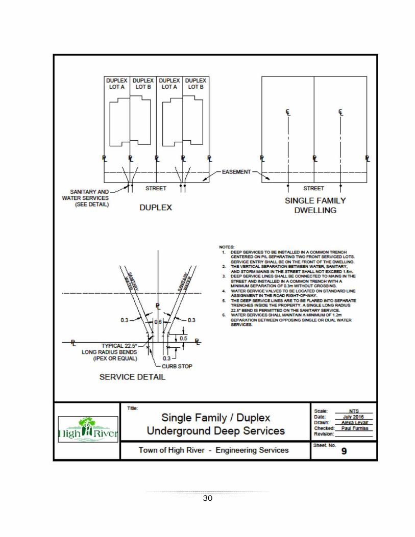
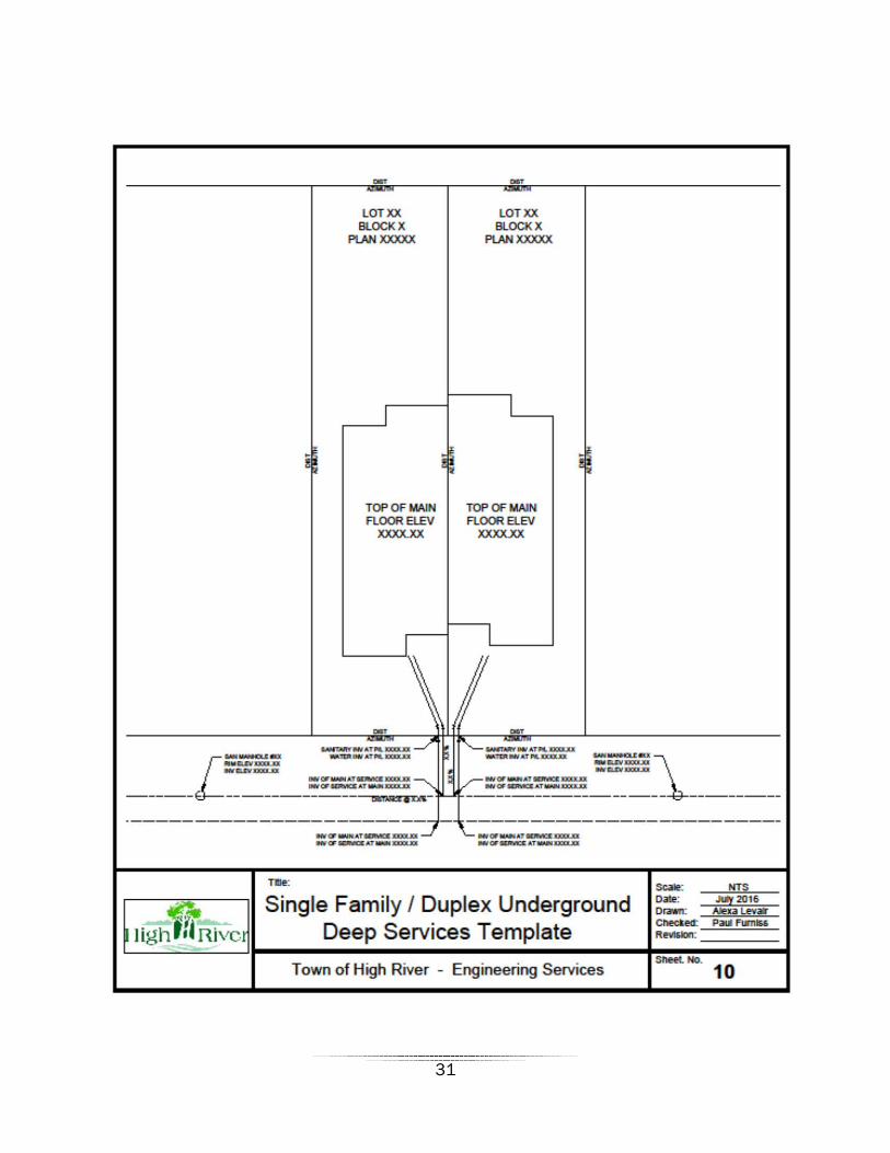
8 LIST OF SHEETS Sheet 1 – Sanitary Sewer Inspection Chamber Sheet 2 – Sanitary Sewer Manhole Lid Sheet 3 – Storm Sewer Manhole Lid Sheet 4 – Irrigation Box Clearance Standards Sheet 5 – Approved Tree List Sheet 6 – Native Tree Species Sheet 7 – Irrigation Report Sheet 8 – Service Card Sheet 9 – Single Family/Duplex Underground Deep Services Sheet 10 – Single Family/Duplex Underground Deep Services Template Sheet 11 – Hydrant Certificate Sheet 12 – Maximum Day Demand Plus Fire Flow
19
20

21

22

23

SHEET 5 – APPROVED TREE LIST
Botanical Name Common Name Decid. / Conif.
Parks / Blvds
Acer negundo Manitoba Maple D P Acer tataricum Tartarian Maple D P Acer tataricum ssp. Ginnala Amur Maple D P Aesculus glabra Ohio Buckeye D P/B Alnus sp. Alder sp. D P Betula fontinalis (Occidentalis) Fountain or Water Birch D P Betula nigra River Birch D P Betula papyrifera Paper Birch D P Betula papyrifera ‘Chickadee’ Chickadee Birch D P Betula pendula ‘Gracilis’ Cutleaf Weeping Birch D P Crataegus arnoldiana Arnold’s Hawthorn D P/B Crataegus cerronis Chocolate Hawthorn D P/B Crataegus chlorosarca Black Hawthorn D P/B Crataegus succulenta Fleshy Hawthorn D P/B Crataegus X mordenensis ‘Snowbird’ Snowbird Hawthorn D P/B
Crataegus X mordenensis ‘Toba’ Toba Hawthorn D P/B Juglans cinerea Butternut D P/B Juglans nigra Black Wanut D P/B Juniperus scopulorum cvs. Rocky Mountain Juniper C P Larix decidua European Larch D P Larix gmelinii (Dahurica) Dahurian Larch D P Larix laricina Tamarack D P Larix lyallii Alpine Larch D P Larix sibirica (Russica) Siberian Larch D P Malus baccata cvs. Siberian Crabapple cvs. D P/B Malus X adstringens cvs. Rosybloom Crabapple cvs. D P/B Phellodendron amurense Amur Corktree D P/B Phellodendron sachalinense Sakhalin Corktree D P/B Picea abies Norway Spruce C P Picea engelmannii Engelmann Spruce C P Picea glauca White Spruce C P Picea glauca ‘Densata’ Black Hills Spruce C P Picea omorika Serbian Spruce C P Picea pungens Colorado Spruce C P Picea pungens cvs. Colorado Spruce cvs. C P Pinus albicaulis Whitebark Pine C P Pinus aristata Bristlecone Pine C P Pinus banksiana Jack Pine C P Pinus cembra Swiss Stone Pine C P
24

Botanical Name Common Name Decid. / Conif.
Parks / Blvds
Pinus contorta latifolia Lodgepole Pine C P Pinus flexilis Limber Pine C P Pinus nigra Austrian Pine C P Pinus ponderosa Ponderosa Pine C P Pinus strobiformis Southwestern White Pine C P/B Pinus strobus Eastern White Pine C P/B Pinus sylvestris Scots Pine C P/B Pinus uncinata (Mugo rostrata) Swiss Mountain Pine C P Populus balsamifera Balsam Poplar D P Populus deltoides (Sargentii) Plains Cottonwood D P Populus jackii ‘Northwest’ Northwest Poplar D P Populus termula ‘Erecta’ Swedish Columnar Aspen D P/B Populus tremuloides Trembling Aspen D P Populus X ‘Assiniboine’ Assiniboine Poplar D P Populus X ‘Brooks #6’ Brooks #6 Poplar D P Populus X ‘Byland Green’ Byland Green Poplar D P Populus X ‘Prairie Sky’ Prairie Sky Poplar D P Populus X ‘Thevestina’ Theves Poplar D P Populus X Canescens ‘Tower” Tower Poplar D P Prunus maackii Amur Cherry D P Prunus mandshurica Apricot D P Prunus nNigra (Americana) Canada Plum D P Prunus X nigrella ‘Muckle’ Muckle Plum D P Pseudotsuga menziesii glauca Blue Douglas Fir C P Pyrus ussuriensis Ussurian Pear D P/B Quercus ellipsoidalis Northern Pin Oak D P/B Quercus marcocarpa Bur Oak D P/B Quercus mongolica Mongolian Oak D P/B Salix acutifolia Sharp Leaf Willow D P Salix alba cvs. White Willow cvs. D P Salix amygdaloides Peach Leaf Willow D P Salix bebbiana Diamond Willow D P Salix eiscolor Pussy Willow D P Salix pentandra Laurel Leaf Willow D P Sorbus americana American Mountain Ash D P Sorbus aucuparia European Mountain Ash D P Sorbus aucuparia cvs. Eg. ‘Rossica’ D P Sorbus eecora Showy Mountain Ash D P Sorbus scopulina Greene’s Mountain Ash D P Syringa pekinensis Peking Tree Lilac D P/B Syringa reticulata Japanese Tree Lilac D P/B Ulmus americana cvs. American Elm D P/B
25

SHEET 6 – NATIVE TREE SPECIES LIST
Botanical Name Common Name Decid. / Conif.
Abies balsamea Balsam Fir C Abies bifolia Rocky Mountain Alpine Fir C Acer negundo Manitoba Maple D Betula fontinalis (Occidentalis) Fountain or Water Birch D Betula neoalaskana Alaska Birch D Betula papyrifera Paper Birch D Juniperus scopulorum cvs. Rocky Mountain Juniper C Larix laricina Tamarack D Larix lyallii Alpine Larch D Larix occidentalis Western Larch D Picea engelmannii Engelmann Spruce C Picea glauca White Spruce C Picea mariana Black Spruce C Pinus albicaulis Whitebark Pine C Pinus banksiana Jack Pine C Pinus contorta latifolia Lodgepole Pine C Pinus flexilis Limber Pine C Pinus monticola Western White Pine C Populus angustifolia Narrowleaf Cottonwood D Populus balsamifera Balsam Poplar D Populus eeltoides (Sargentii) Plains Cottonwood D Populus tremuloides Trembling Aspen D Pseudotsuga menziesii glauca Rocky Mountain Douglas Fir C Salix amygdaloides Peach Leaf Willow D Salix scouleriana Scouler’s Willow D
26

27

28

29
30
31
32

Docu
ment:
M:\2
6400
\2644
8_Hig
h_Riv
er_IM
P_Ph
ase2
_Upd
ate\02
_CAD
D\20
_Draf
ting\2
01_G
IS Fig
ures\W
ater F
igures
\2.0 E
xistin
g Ass
essm
ent\F
igure
12 - E
xistin
g Ass
essm
ent_M
DD +
FF.m
xdDa
te: 3/
23/20
17
_̂
_̂
#0
_̂
325
250 300275
225200
175
150
100 125
35075
375
400
50
425
450
25
475
0
25
275
75
300
450
200
50
100 100
425
175
225
75
175
450
400
400
275425
300
100
50
225
125
50
350
200
125375
150
75
425275
225
350
300
250
75
225
125
250
50
250
275
100
275
175
125
150
125
175
100250
200
325
50
125
325
225
100
25
425 375
125
150
300
175
200
75
300
100
325
25
200
250
325
225
75
375
200
175
25
25
200
300
225
150175
150 125
275
75
400
300
25
175
350
175
225
375
250
175
250
225
250
25
75275
275
300
475
475
425
250
100
150
225
250
150
150
450
150125
175
50
275
300
200
175
50
150350
75
175
2575
25
150
250
375
275
125
150
125
175
75
200
50
200
225
425
150
150150 175
125
75
225
150
400
100
150
375
150
175
125
100
225
25
200
225
375
250
125
25075
275225
75
100
100
175
150
50
350
300
150
250
250
75
400175
375
125
350
100
400
400
100
25
350
225
125
125
375100
225
75
200
150
25
275
175 27575
325
100
175
300
125
300
150125
125
150
200
125
200
300
250
175275
125200
125
100
350
175
50
75
375
400
175
50325
125
225
50
125
300
175
225
225425
Main Reservoir
East to Mazeppa
North to Cargill and Aldersyde
South to Cayley
9 ST.
W
7 ST.
W
21 S
T. E
7 ST.
SE
20 S
T. E
12 ST. SE
2 AVE. NE
8 AVE. SE 20 S
T. SE
HIGH
WAY 2
14 S
T. SE
HIGH
WAY 2
A
11 AVE. SE
12 AVE. SE
MACLEOD TR.
CENTRE AVE.
HIGH
WOO
D TR
.
BEACH WAY SW
RIVE
RSID
E DR
.
MONTEITH DR. SE
HIGH COUNTRY DR.
SECONDARY ROAD 543
THE TOWN OF HIGH RIVER2011 IMP UPDATE PHASE 2
WATER DISTRIBUTION SYSTEMEXISTING SYSTEM ANALYSIS
MAXIMUM DAY DEMAND PLUS FIRE FLOW
0 250 500 750 1,000125Meters
1:20,000
¹FIGURE 3.12
L e g e n dL e g e n d#0 Main Reservoir
_̂ Out of Town DemandDistribution Watermain Size
Less than 100mm100mm150mm200mm250mm300mm350mm400mm
Available Fire FlowLess than 76L/s76 - 100L/s100 - 150L/s150 - 200L/s200 - 227L/s227 - 265L/s265 - 300L/s300 - 500L/s
No part of this map may be reproduced in any form, or by any means without written permission and agreement from the Town of High River. The Town of High River provides this information in good faith, but accepts no responsibility or liability arising from any errors in accuracy, incorrect, incomplete, misleading or omitted information, or the improper use of the information provided within.