Embed Size (px)
Citation preview
Towards Enhanced Security for AutomotiveOperating Systems
by
Maksym Hryhorenko
A thesissubmitted to Florida Institute of Technology
in partial fulfillment of the requirementsfor the degree of
Master of Sciencein
Information Assurance and Cybersecurity
Melbourne, FloridaDecember, 2018

c⃝ Copyright 2018 Maksym Hryhorenko
All Rights Reserved
The author grants permission to make single copies.

We the undersigned committeehereby approve the attached thesis
Towards Enhanced Security for Automotive Operating Systemsby
Maksym Hryhorenko
William Allen, Ph.D.Associate ProfessorComputer Engineering and SciencesCommittee Chair
Heather Crawford, Ph.D.Assistant ProfessorComputer Engineering and SciencesCommittee Member
Veton Kepuska, Ph.D.Associate ProfessorComputer Engineering and SciencesOutside Committee Member
Philip Bernhard, Ph.D.Associate ProfessorComputer Engineering and SciencesAcademic Unit Head Department

ABSTRACT
Title:
Towards Enhanced Security for Automotive Operating Systems
Author:
Maksym Hryhorenko
Major Advisor:
William Allen, Ph.D.
Modern automotive infotainment systems are represented by highly complex compo-
nents with broad functionality and network capabilities. As a result, they are becoming
more exposed to the outer world, thus turning into potentially lucrative targets for
remote cyber attacks. In the worst case scenario, an attacker could gain complete
control over critical vehicle’s systems, for instance, steering, braking, engine, etc. This
thesis proposes security hardening features based on ARM’s TrustZone technology for
infotainment systems that ensures confidentiality and integrity of critical applications.
In addition, we present a technique that allows to mitigate the impact of certain attacks
on the car’s internal network. In contrast to existing solutions, our security features do
not require separate hardware and can be implemented on the same system-on-chip as
an infotainment system. Finally, we evaluated the implemented approach and demon-
strated its capabilities to successfully mitigate potential attack vectors created by a
compromised operating system, specifically, fake input injection, screen capture, and
overlay attacks.
iii
Table of Contents
1 Introduction 1
1.1 Threat Model . . . . . . . . . . . . . . . . . . . . . . . . . . . . . . 2
1.2 Existing Solutions . . . . . . . . . . . . . . . . . . . . . . . . . . . . 4
1.3 Proposed Solution . . . . . . . . . . . . . . . . . . . . . . . . . . . . 6
2 Background 8
2.1 Related Work . . . . . . . . . . . . . . . . . . . . . . . . . . . . . . 9
2.2 ARM TrustZone . . . . . . . . . . . . . . . . . . . . . . . . . . . . . 10
2.3 TrustShadow . . . . . . . . . . . . . . . . . . . . . . . . . . . . . . . 11
2.4 Automotive Grade Linux . . . . . . . . . . . . . . . . . . . . . . . . . 12
2.5 i.MX 6 Board . . . . . . . . . . . . . . . . . . . . . . . . . . . . . . 13
2.6 Control Area Network Standard (CAN) . . . . . . . . . . . . . . . . . 13
2.6.1 FlexCAN . . . . . . . . . . . . . . . . . . . . . . . . . . . . . 15
3 Design 17
3.1 Architecture Overview . . . . . . . . . . . . . . . . . . . . . . . . . . 17
3.2 Trusted Execution Environment . . . . . . . . . . . . . . . . . . . . . 18
3.3 Secure User Interface . . . . . . . . . . . . . . . . . . . . . . . . . . 19
3.4 Secure Network Channel . . . . . . . . . . . . . . . . . . . . . . . . . 22
3.5 CAN Bus Communication Routing . . . . . . . . . . . . . . . . . . . 23
iv

4 Implementation 26
4.1 Framework for Embedded Linux Development . . . . . . . . . . . . . 26
4.2 TrustZone Address Space Controller . . . . . . . . . . . . . . . . . . . 28
4.3 Secure User Interface . . . . . . . . . . . . . . . . . . . . . . . . . . 29
4.4 Secure Network Channel . . . . . . . . . . . . . . . . . . . . . . . . . 31
4.5 CAN Communication Routing . . . . . . . . . . . . . . . . . . . . . . 32
5 Evaluation 33
5.1 Test Bed Overview . . . . . . . . . . . . . . . . . . . . . . . . . . . . 33
5.2 Features Overview and Security Evaluation . . . . . . . . . . . . . . . 34
6 Conclusion 40
A Yocto Layers 45
B Framebuffer Structures 46
C Input Devices 49
D Touch Logger 52
E FlexCAN Message Buffer Data Structure 56
v

List of Figures
1.1 CAN Bus interconnectivity and entry channels . . . . . . . . . . . . . 3
2.1 FlexCAN message buffer . . . . . . . . . . . . . . . . . . . . . . . . . 14
2.2 CAN frame . . . . . . . . . . . . . . . . . . . . . . . . . . . . . . . . 14
2.3 FlexCAN message buffer [24] . . . . . . . . . . . . . . . . . . . . . . 16
3.1 System’s architecture . . . . . . . . . . . . . . . . . . . . . . . . . . 18
3.2 Secure display service setup routine . . . . . . . . . . . . . . . . . . . 21
3.3 Secure network channel flow chart . . . . . . . . . . . . . . . . . . . . 23
3.4 CAN routing flow chart . . . . . . . . . . . . . . . . . . . . . . . . . 24
5.1 i.MX6 SabreSD . . . . . . . . . . . . . . . . . . . . . . . . . . . . . 34
5.2 AGL interface . . . . . . . . . . . . . . . . . . . . . . . . . . . . . . 35
5.3 Test Scenario . . . . . . . . . . . . . . . . . . . . . . . . . . . . . . 36
5.4 Secure UI Session . . . . . . . . . . . . . . . . . . . . . . . . . . . . 37
5.5 CAN Bus Message Injection . . . . . . . . . . . . . . . . . . . . . . . 39
5.6 CAN Bus Attack Filtered . . . . . . . . . . . . . . . . . . . . . . . . 39
vi

List of Tables
1.1 Various malicious impact on automotive systems . . . . . . . . . . . . 4
vii

List of Abbreviations
AGL Automotive Grade Linux
ARM Advance RISC Machine
CAN Control Area Network
ECU Electronic Control Unit
HVAC Heating, Ventilation and Air Conditioning
IVI In-Vehicle Infotainment
LVDS Low-voltage Differential Signaling
MMU Memory Management Unit
SDK Software Development Kit
SoC System-on-Chip
TEE Trusted Execution Environment
TZASC TrustZone Address Space Controller
UI User Interface
viii
Acknowledgements
I would like to express my profound gratitude to my thesis advisors Shengzhi Zhang and
William Allen for remarkable support they provided me during the research. They con-
stantly pointed me towards the right direction, supplied me with highly useful research
material and presented valuable comments on this thesis.
I would also like to thank my parents and brother for providing me with unfailing
support and continuous encouragement throughout my years of study and research
and during the whole writing process of my master’s thesis.
ix

Chapter 1
Introduction
Contemporary automotive systems are represented by the tremendous number of com-
ponents and microcomputers. In order to fully utilize the system’s technical capabilities
and ensure efficient communication, the Control Area Network (CAN) bus standard
was developed. CAN is a robust message protocol, that implies a connection of all
car systems to a single bus. Hence, every node in the automotive system’s network
can receive from as well as send messages to every other component. CAN network
messages can be informative, which provide state of a certain vehicular unit, e.g. dash-
board unit outputs vehicle tires status by reading tire pressure indicators, or control,
which change the state of a component, e.g. Adaptive Cruise Control unit sends the
command message to braking system in order to reduce vehicle’s speed. Although
CAN communication standard offers significant benefits to efficiency, extensibility and
cost of automotive systems, it creates dangerous attack vectors, where a single com-
promised unit opens access to critical vehicle systems, for instance, engine control unit,
steering or braking system [1].
1

1.1 Threat Model
Traditionally, the node with the richest network capabilities appears to be the weakest
link of a system from a security perspective. In case of automotive security, the
most exposed element is In-Vehicle Infotainment (IVI) — a sophisticated, feature-rich
component that comprises a plethora of hardware and software solutions, including
audio and video entertainment, information display with vehicle’s condition, radio,
navigation, air-conditioning. In addition, in modern cars can also include Bluetooth
and USB connectivity (e.g. with a smartphone), in-car internet (through cellular or
satellite network), Wi-Fi, integration with mobile devices, in-house applications and
widgets (e.g. weather, news, browser), parking assist, braking assist. IVI systems are
continuously being improved and expanded by car manufactures. Figure 1.1 shows
interconnectivity of components in the car’s CAN network and entry channels for a
remote attack.
More and more automobile’s Electronic Control Units (ECU) become accessible through
infotainment system to facilitate driver’s experience. Unfortunately, additional func-
tionality exposes more car critical components for potential malicious attacks. In ad-
dition, considering network connectivity capabilities of IVI, attacks could be executed
not only through physical access to the vehicle, but remotely as well.
In this way, in-vehicle infotainment security raises significant concerns in the automotive
industry. Compromised IVI head unit, with escalated privileges, is capable of accessing
a vehicle’s internal bus as well as injecting malicious CAN control messages, thus
manipulating critical ECUs. Table 1.1 outlines /potential malicious impact on an
automobile in the case when a compromised node takes control over the CAN bus.
In [2], Checkoway et al. explored attack surface in modern automotive systems. The
2

Figure 1.1: CAN Bus interconnectivity and entry channels
authors discovered and presented an assembly of vulnerabilities in various vehicle’s
ECUs. For every scenario, complete control over the vehicle was obtained. Vulnerable
entry channels include a media player (malicious WMA file), Bluetooth (through the
paired and unpaired device), diagnostic PassThru device, telematics (aqLink protocol),
a cellular network, an infected smartphone connected to the car.
However, the strongest motivation for this thesis was the presentation on remote car
exploitation by Charlie Miller and Chris Valasek [3]. The authors conducted a com-
prehensive security assessment of genuine, recent for those time, 2014 Jeep Cherokee,
that was equipped with a plethora of features, including driving assist, collision warn-
ing, lane departure warning, park assist. The infotainment system of the car utilized
Uconnect radio, that encompassed navigation, Wi-Fi connectivity, apps and cellular
3
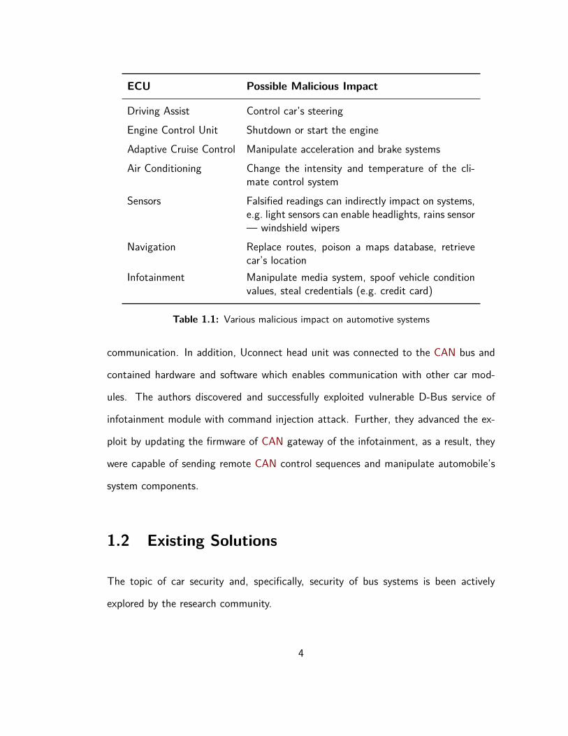
ECU Possible Malicious Impact
Driving Assist Control car’s steeringEngine Control Unit Shutdown or start the engineAdaptive Cruise Control Manipulate acceleration and brake systemsAir Conditioning Change the intensity and temperature of the cli-
mate control systemSensors Falsified readings can indirectly impact on systems,
e.g. light sensors can enable headlights, rains sensor— windshield wipers
Navigation Replace routes, poison a maps database, retrievecar’s location
Infotainment Manipulate media system, spoof vehicle conditionvalues, steal credentials (e.g. credit card)
Table 1.1: Various malicious impact on automotive systems
communication. In addition, Uconnect head unit was connected to the CAN bus and
contained hardware and software which enables communication with other car mod-
ules. The authors discovered and successfully exploited vulnerable D-Bus service of
infotainment module with command injection attack. Further, they advanced the ex-
ploit by updating the firmware of CAN gateway of the infotainment, as a result, they
were capable of sending remote CAN control sequences and manipulate automobile’s
system components.
1.2 Existing Solutions
The topic of car security and, specifically, security of bus systems is been actively
explored by the research community.
4

One of the solutions, proposed by Hamad et al. in [4], describes a communication frame-
work for a network of embedded systems with microkernel-based architecture. The
approach implies that every component in a car network is running on a microkernel-
based operating system. The authors implemented a communication module (firewall)
that defines all permitted communication paths between ECUs as well as ensures fine-
grained based access control and secure device communication through authorization.
Combination of ECUs running on microkenrel-based OS with comprehensive process
isolation and a separate firewall module provides a strong security model for automotive
systems. Unfortunately, microkernel suffers from inter-process messaging overhead and
as a result slower than the ubiquitous monolithic kernel, especially with sophisticated
and feature-rich components, e.g. infotainment systems, running on top of it. In ad-
dition, this security mechanism requires an installation of the external component in
CAN network — firewall module — for each ECU, thus complicating implementation
on existing cars.
Other security schemes rely on encryption and integrity checks of CAN messages. One
of such solutions was proposed by Van Herrewege et al. in [5]. The authors developed
and presented an authentication protocol based on preshared keys, HMAC and mes-
sage id tracking. Every node in the network assumed to have predefined 128 bit key
storage, that was assigned during the vehicle’s development phase and deployed in a
tamper-resistant private storage. This security model allows to mitigate spoofing and
replay attacks. Nevertheless, this solution is not capable of protecting components
that require a connection with the compromised node by design, e.g. climate control
and compromised infotainment unit. Moreover, due to the overhead of software im-
plementation of cryptographic primitives, the proposed approach is not practical for
embedded systems with real-time requirements.
5

Therefore, this thesis proposes a different method of securing automotive systems,
that is primarily focused on hardening of its infotainment component. The proposed
approach utilizes hardware hypervisor technology on ARM processors — TrustZone
— and can be built on top of the traditional monolithic kernel, thus compatible with
most available entertainment OS. The solution ensures, that even compromised kernel
(e.g. rootkit) would not be able to tamper memory of critical applications running in
this environment, for instance, Heating, Ventilation and Air Conditioning (HVAC) or
payment module (for in-car app purchases).
1.3 Proposed Solution
Four security hardening features are presented in this thesis: a trusted execution en-
vironment, secure user interface, secure network channel and CAN communication
routing.
Trusted Execution Environment (TEE): In case of compromised OS, memory of
critical applications should be protected from accessing and tampering by a malicious
component with elevated privileges. The solution is heavily based on TrustShadow
security system [6], that was adapted for newer Linux kernel (from 3.18 to 4.8) version
and automotive Linux distributive (AGL).
Secure user interface (UI): This component provides a trusted path between user
and applications which are running in TEE. In this thesis, the prototype of secure UI
is presented by a confirmation window that always appears on top of the home menu
screen and protected from overriding and overlaying by compromised OS.
Secure network channel: In order to reduce trusted computing base (TCB), Trust-
6

Shadow relies on OS components, including network interaction. Thus, protected
applications will expose critical data while utilizing the network interface provided by
OS drivers. To prevent this, a secure network channel was developed, that ensures
confidentiality and integrity of data while using the untrusted network driver of OS.
CAN communication routing: To ensure only allowed operations are requested by
IVI system, filter component was implemented in TEE as well as untrusted OS was
isolated from direct access to the CAN bus.
The rest of the paper is organized as follows: Chapter 2 presents background infor-
mation on technologies and hardware that were used for the research. Chapter 3
describes architecture and design of the solution. Chapter 4 explains implementation
details. Chapter 5 presents performance evaluation. Chapter 6 concludes and summa-
rizes proposed security model.
7

Chapter 2
Background
In this chapter, we will overview prior research on topics of automotive and industrial
security, filtering of malicious messages in networks, least privilege security principle,
and hardware-enforced isolation. In addition, we will describe different technologies,
software and hardware that were utilized in the design and implementation of the
proposed security model. In particular, the topics of interest are:
ARM TrustZone a hardware-enforced security mechanism;
TrustShadow a particular implementation of security solution on top of TrustZone;
Automotive Grade Linux fully open source Linux distribution and framework de-
signed for automotive systems.
i.MX 6 a developer’s board with enabled TrustZone support.
8

2.1 Related Work
Concerns regarding automotive security are frequently raised by the research com-
munity, as new attack vectors and security flaws are being discovered in automobile
systems. In the paper [7], Wright overviewed attacks on vehicle systems which were
accomplished by injecting malicious code into the on-board computer diagnostics port.
The results of this attack were severe, as the research team could remotely control a
car, start and stop the engine, lock and unlock doors through Bluetooth and cellular
services. The author concluded, that due to the unrestricted nature of the CAN bus,
every connected device with wireless capabilities presents a potential entry point for re-
mote attacks. Eckhoff and Sommer raise concerns of security and privacy preservation
in current and future standards of vehicular networks in [8]. In the paper [9], Whalen
et al. presented their framework for the development of a secure architecture for vehic-
ular systems, specifically for military unmanned aerial vehicles. Their solution is based
on microkernel OS architecture and efficient domain-specific programming languages
(Ivory) which guarantees the absence of certain classes of memory errors, e.g. overflow
and underflow, as well as provides significant integration with cryptographic libraries.
Security in industrial control systems (SCADA) is a related to vehicle security topic as
the Modbus protocol, that is commonly used in such systems, closely resembles the
CAN bus. In their research [10], Gao and Morris described a plethora of cyber attacks
on SCADA systems, including response and command injections and denial of service.
In addition, the authors presented rules for the SNORT intrusion detection system to
mitigate the whole set of attacks.
Hardware-enforced security and Trusted Platform Module (TPM) use cases and benefits
for security in embedded systems are discussed by Osborn and Challener in [11]. In the
9

paper [12], Asokan et. al introduced multiple security architectures and approaches for
mobile platforms using hardware-enforced isolation that can provide a trusted execution
environment for critical applications and libraries.
The topic of incoming and outgoing message filtering is thoroughly discussed in [13]
and [14].
Lampson et. al introduced the theoretic access control model with enforcement of least-
privilege principal for nodes in a distributed system [15]. In [16], Saltzer and Schroeder
presented a detailed tutorial into the mechanics of information protection, in which they
described different approaches for access control, authorization, least-privilege principle
and other security mechanisms.
2.2 ARM TrustZone
TrustZone is a hardware architecture, implemented on System-on-Chip (SoC) devices
with ARM processors, that provides a security framework to counter many threats in
embedded systems. The primary feature of TrustZone is partitioning of all hardware and
software resources in one of two worlds — secure, for security subsystems and sensitive
assets, and normal, for everything else. Both worlds have independent memory address
space. The TrustZone hardware architecture ensures that no assets in the secure world
can be accessed from the normal world [17]. This isolation provides protection to
trusted applications against non-trusted, which were installed by user and run in the
normal OS.
TrustZone enabled processors can run in two states: secure and non-secure. In non-
secure state processor can access assets designated only for the normal world. In secure
10

— both secure and normal world. To support code execution from two worlds in time-
sliced fashion, ARM processor has specifically allocated physical core. Access control
is enforced with non-secure (NS) bit — an extension control signal in ARM SoC for
read and write channels on the main system bus. If an application in the normal world
attempts to access protected assets, the operation fails silently or generates an error.
The world switch operation is issued with a smc instruction and is handled through
monitor mode software that saves and restores system state and transfers execution
control. The hardware provides two virtual memory management units (MMU) for
proper isolation of memory address space of both worlds. TrustZone secure world is
booted before the normal OS, thus ensuring proper validation of the kernel image and
preventing an attacker from replacing it with a malicious one [6].
Therefore, embedded systems developers have many security architecture approaches.
Commonly, a secure world is presented by the compact kernel with implemented secure
service, e.g. key management, an online payment module, one-time passwords gener-
ation, secure storage, SSL library, and the normal world with a feature-rich operating
environment that calls services in the secure world.
2.3 TrustShadow
TrustShadow is a security solution that utilizes TrustZone technology to protect legacy
applications from untrusted operating systems [6]. This solution ensures that security-
critical applications will be running in a trusted execution environment isolated from
potentially compromised OS. The key feature of TrustShadow is a lightweight runtime
system that provides a communication bridge between protected applications and nor-
11

mal OS, in particular, its services, e.g. network drivers, IPC, signal handling, libraries
etc. Therefore, any application, that was developed for normal OS can run in the
secure world without source code modifications. TrustShadow was implemented and
tested on i.MX 6 SabreSD developer’s board [6]. It supports Linux Kernel version 3.18.
TrustShadow provides a particularly useful foundation for security solutions based on
Automotive Grade Linux (AGL) distribution and TrustZone enabled hardware as impor-
tant components, e.g. secure monitor and runtime system, is already implemented and
can be reused. Therefore, it was utilized as a framework for security model presented
in this thesis.
2.4 Automotive Grade Linux
Automotive Grade Linux is an open-source infotainment OS and application framework
for automotive systems that is based on Linux Kernel. The primary purpose of AGL is
to provide a common platform that can support car apps from various manufacturers.
Hence, simplifying apps development and creating more opportunities for the vehicle
applications market, similar to the mobile market.
Currently, AGL is supplied with a collection of apps and widgets, specifically media
player, mixer, HVAC, vehicle state info (tire, fuel, speed), phone, navigation, Bluetooth,
apps manager. Moreover, the platform is highly customizable and easily extendable.
AGL is particularly useful as a development platform for the thesis, as it possesses broad
functionality and is well documented. Furthermore, AGL is a promising platform that is
actively supported and promoted by Linux Foundations, as a result, car manufactures
recently started adopting it as their primary infotainment system [18].
12

2.5 i.MX 6 Board
i.MX 6 series is a family of Systems-on-Chip developed by Freescale Semiconduc-
tor [19]. i.MX boards are particularly interesting for the topic’s research as they are
supplied with ARM CPU and, what is more important, its TrustZone feature is unre-
stricted, in contrast to cheaper ARM boards from other manufacturers, like Samsung,
NVIDIA. Furthermore, i.MX series features models that are specifically designed for car
infotainment systems (AI series), that has similar hardware, besides additional media
inputs/outputs and connectors (to CAN Bus etc.), as general purpose boards. Hence,
general purpose i.MX 6 board presents a universal and convenient testing bed.
2.6 Control Area Network Standard (CAN)
The CAN communication protocol is carrier-sense, broadcast message protocol. The
carrier-sense nature implies, that transmitter ensures in absence of traffic in the network
before sending a message. CAN implements collision detection with the help of message
arbitration. Each CAN message type is supplied with preprogrammed identifier field
that defines its priority. Higher priority messages win bus access [20]. Important
features of the CAN protocol are high reliability, due to its ability to detect all single-
bit errors as well as multi-bit errors with sufficient probability, and fault confinement
that prevents a faulty single node from corrupting the network [21].
CAN communication model can be decomposed into three layers: application, data
link and physical (Figure 2.1). Physical layer includes CAN transceivers, connectors
and bus-line. Commonly, twisted-pair copper cables are utilized as a transmission
medium. Next level is presented by Data link layer. Data link protocols (Classic CAN
13

Figure 2.1: FlexCAN message buffer
or CAN Extended) define process data object format — CAN frame — a data unit
on the CAN network. Finally, Application layer is responsible for device addressing,
transportation of data blocks larger than one frame and other high level tasks. Unlike
data link, the application layer is not standardized, thus every manufacturer has its own
implementation, e.g. EnergyBus is used in electric bicycles and pedelecs [22], MilCan
— in military vehicles [23].
Figure 2.2: CAN frame
CAN frame. Structure of data link layer frame is presented in Figure 2.2. The
meaning and purpose of each field is next:
• SOF — start of frame, marks start of message.
• Identifier — defines priority of messages and their function. This field is impor-
tant for our security research, as other nodes identify and process messages based
14

on their ID, e.g. message with ID 01FC controls tachometer, turn signal ID is
05CE (numbers are taken from [3], however, different car models have different
IDs). Lower IDs have higher priority. Precedence is important for CAN messages
to ensure critical systems instant response in case of emergency.
• RTR — remote transmission request, bit is set when node is waiting for certain
information from other node.
• IDE — identifier extension, bit is set if frame format with extended length of
identifier is being used.
• r0 — reserved, not used.
• DLC — size of data being transmitted.
• Data — application data.
• CRC — checksum for error detection.
• ACK — acknowledgement bit. Every node should send a signal that data frame
was received without errors. Otherwise, sender repeats a broadcast.
• EOF — end of frame mark.
2.6.1 FlexCAN
FlexCAN controller is a particular implementation of the CAN protocol on i.MX SoCs
boards. The controller holds queue of up to 64 retrieved messages or messages ready
for sending. All messages have specific format. FlexCAN message buffer structure is
presented in Figure 2.3.
The meaning of each field is next:
• CODE — indicates status of buffer, e.g. 0000 buffer not active/ready, 0100
buffer is active and empty.
15

Figure 2.3: FlexCAN message buffer [24]
• SRR — substitute remote request, same as RTR but used only in extended
format.
• IDE — identifier extension, bit is set if frame format with extended length of
identifier is being used.
• RTR — remote transmission request, bit is set when node is waiting for certain
information from other node.
• LENGTH — size of data being transmitted.
• TIME STAMP — time when message buffer was captured since system boot.
• PRIO — additional local priority.
• Identifier — same as in classic CAN frame.
• Data — up to 8 bytes of data.
In this chapter, we overviewed prior research on the related topics and described tech-
nologies, software and hardware that were utilized in our solution, including ARM
TrustZone, AGL, TrustShadow, i.MX 6 development board and CAN communication
protocol.
16

Chapter 3
Design
In this chapter we will describe overall architecture as well as design details of proposed
security hardening features.
3.1 Architecture Overview
Traditionally, systems, that are based on TrustZone secure architecture, are split into
two layers or worlds: normal, where a feature-rich OS is running, and secure. The
approach closely resembles kernel-user space paradigm, specifically, the secure world
has unlimited access to all devices and memory and at the same time defines access
privileges for the normal world. There are two ways to switch from the normal world to
secure: instruction from the normal world and secure interrupt (interrupt that signals
on protected peripheral). Commonly, worlds communication occurs through a special
piece of software that is running in TEE — monitor. The monitor delegates requests
to various trusted applications or drivers and returns results to the normal world. Data
17

exchange between untrusted and trusted environments occurs through CPU registers
or, if the size of a message is larger than the maximum register’s size (32 bits for ARM
32-bit architecture), through specifically allocated shared memory region.
Figure 3.1: System’s architecture
The architecture, presented in Figure 3.1, specifies components that were utilized in
the solution, their corresponding execution environment and communication. In the
next sections, we will describe the role of each component in security support of the
IVI system.
3.2 Trusted Execution Environment
Trusted Execution Environment (TEE) is provided by TrustShadow [6] system. In gen-
eral, autonomous applications that continuously run in the secure world, e.g. HVAC
front end or a payment module, require CPU time to execute. However, as described
earlier, execution flow transfer is initiated only by the normal world or secure periph-
eral interrupt. Thus, the one way to solve this problem is to protect every hardware
18

component that secure applications could utilize. This approach is highly inefficient
and negates the benefit of small TCB of TrustShadow, as every protected compo-
nent would require implemented driver in the secure world. The solution implemented
in [6] for secure applications implies the creation of its counterpart in the normal world
— shadow — that retrieves CPU time as every other non-secure process. However,
memory of shadow counterpart does not contain any critical data as it resides in the
secure world. Every system call, that shadow makes, is transferred to the secure world
monitor, which then reads memory of secure application, supplies system call with
authentic parameters and delegates it back to OS. After system call completes, OS
transfers control back to the monitor, which then supplies the secure application with
call return results and switches back to the normal world. On the architecture diagram,
shadows are located in user memory space.
3.3 Secure User Interface
In order to ensure to protect user interactions with the secure world from a com-
promised OS while reusing insecure video drivers, we propose a scheme that involves
direct memory access of image processing unit (IPU), so called framebuffer operations.
Framebuffer is a region of RAM containing a pixel map of the display. Therefore,
video output can be manipulated by writing pixel color values into this memory region.
The format of pixels, data structure size, region size depends on displays characteristics
and settings, e.g. display’s resolution or color depth.
Commonly, embedded devices configured to support multiple framebuffers per display
— background and foreground. Our board supports 6 framebuffers as it is supplied with
19

three video output sockets — HDMI and two Low-voltage Differential Signaling (LVDS)
connectors. The multi-layer setup is very convenient in case of two independent video
sources running simultaneously.
For our solution, we decided to utilize foreground framebuffer. Secure kernel does
not support video drivers and is not aware of IPU’s memory region. Thus, it is a
normal world’s responsibility to setup framebuffers including mapping to kernel’s virtual
memory space. After setup was completed, normal world kernel module TZ Support
Driver will extract required characteristics of foreground framebuffer, including physical
address and memory region size, and send them through shared memory to the secure
world. After receiving framebuffer’s information, the secure world sets the specified
memory region as secure-only and setups display service that provides API for simple
graphics drawing. The normal world cannot capture foreground layer and any attempt
to access or change protected framebuffer will result in data abort interrupt, which by
default is not handled and causes a system reboot. After drawing an object on the
foreground layer, execution flow returns to the normal world. Setup routine of secure
display service is presented in Figure 3.2
Transferring touch events: To provide interactivity, display service supports touch
gestures. Touch events are handled by normal OS drivers and coordinates are trans-
ferred to the secure world by support driver. To reduce performance impact, data
transfer and world switch occur only when secure display service is active, in other
words, when there is any active graphics content. To capture touch events, we have
implemented an event sniffer, that reads Linux input device log and notifies TZ support
driver with every update.
After secure display service receives touch coordinates, it confirms whether control ele-
20
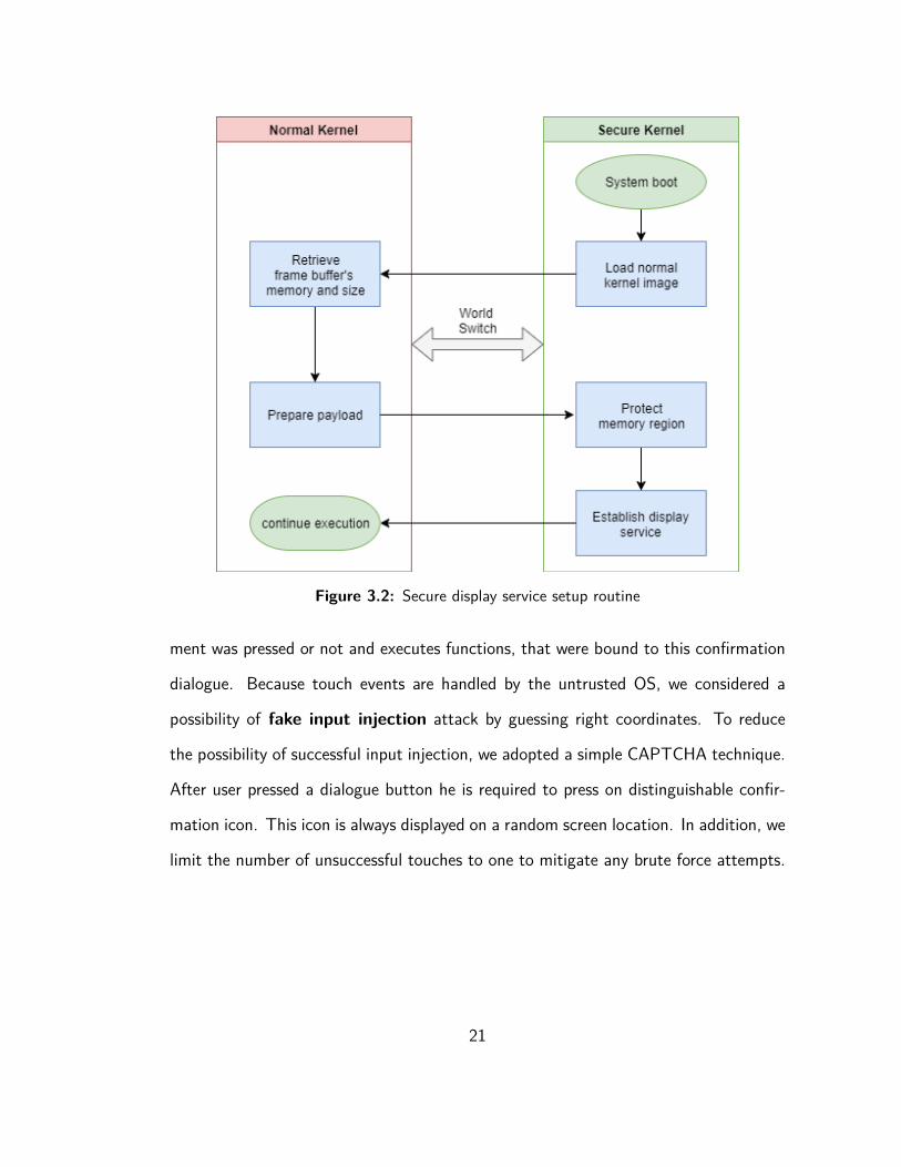
Figure 3.2: Secure display service setup routine
ment was pressed or not and executes functions, that were bound to this confirmation
dialogue. Because touch events are handled by the untrusted OS, we considered a
possibility of fake input injection attack by guessing right coordinates. To reduce
the possibility of successful input injection, we adopted a simple CAPTCHA technique.
After user pressed a dialogue button he is required to press on distinguishable confir-
mation icon. This icon is always displayed on a random screen location. In addition, we
limit the number of unsuccessful touches to one to mitigate any brute force attempts.
21

3.4 Secure Network Channel
Even though the memory of trusted applications is protected, the malicious OS still has
an advantage over applications that utilize network capabilities as sent and received
data can be intercepted, tampered by middleware.
A man-in-the-middle attack is commonly mitigated by strong encryption for confiden-
tiality with attached hashed message authentication code (HMAC) for integrity. In
our case, we cannot trust cryptographic (SSL) libraries that are located in the normal
world. Fortunately, i.MX 6 boards have hardware acceleration support for common
crypto algorithms as well as random number generator module. Moreover, the board’s
SDK provides cryptographic APIs.
Therefore, for secure network delegation, trusted OS encrypts payload before transfer-
ring back to the normal world. The algorithm is presented in Figure 3.3 and described
below:
• A Shadow application invokes system call request for the socket send operation.
• OS receives request and transfers system call details to the secure world.
• Monitor checks whether this application requires encryption. If yes, encrypts
payload with public key of the service that this application sends request to.
• Monitor returns encrypted payload to the normal OS.
• Normal OS executes the socket send system call.
Thus, it is possible to implement any secure negotiation sequence, including traditional
SSL/TLS handshake. However, this approach requires to store certificate authority
22

Figure 3.3: Secure network channel flow chart
public keys on protected storage. For simplicity sake, we hard coded secrets in the
secure OS image. Even though public keys do not have to be secret, we need to ensure
their integrity to prevent addition or overwriting with fraudulent certificates.
3.5 CAN Bus Communication Routing
With the capability of TrustZone enabled CPU to set the peripheral device as secure,
we can implement a trusted component that will filter out improper messages from the
malicious IVI system and pass legitimate messages.
CAN is broadcast protocol. Every CAN frame is contains message ID. Connected to
the network devices accept messages with a specific ID and ignore others. Message
acceptance filters are stored on internal memory of CAN interface peripheral. Hence, if
a malicious OS has direct access to the CAN device, it can reprogram filters to accept
all messages and, as a result, sniff the entire network. Moreover, the untrusted system
is capable of queuing any message for broadcast, whether by utilizing drivers or by
23

writing directly into CAN interface registers.
To mitigate such attack, we propose to completely isolate CAN peripheral from the
normal world, yet expose send API through support driver or system call. When appli-
cation issues broadcast request through support driver, the latter stores request details
in shared memory and executes world switch routine. In the secure world, the monitor
passes the request to CAN service which checks the message ID of a frame and ensures
only allowed values are being supplied. After that, service uses CAN driver to send the
message. The CAN routing algorithm for send operation is presented in Figure 3.4
Figure 3.4: CAN routing flow chart
The receiving message routine is more complex. When CAN interface accepts a mes-
sage, it sends interrupt request (IRQ), which CPU then delegates to the specific handler
in the interrupt vector table of OS. In the case of TrustZone systems, both worlds have
their own interrupt vector table (IVT). Secure world handlers have priority. As we pre-
viously mentioned, switch to secure world can occur by a secure interrupt. Therefore,
by specifying function handler for IRQ, masking out all interrupts, except from CAN
interface, by interrupt number, the secure world can receive CAN message, analyze
24

it and then trap this IRQ to normal world’s IVT. This is a complex procedure that
requires deep knowledge of board internals as well as low level programming and due
to time constraints was not implemented in the thesis.
In this chapter, we introduced the architecture of our solution. We described compo-
nents, their structure and role in our security mechanism.
25

Chapter 4
Implementation
In this chapter we will describe implementation details, technologies and frameworks
that were utilized to develop and build our solution.
4.1 Framework for Embedded Linux Development
Building custom solutions for embedded systems and Internet-of-Things products is
not as trivial as building applications on existing operating system. Embedded Linux
systems commonly consist of three components:
• Boot loader — startup code, that powers up and initializes all device’s peripher-
als, verifies hardware’s correct functionality, loads kernel image into memory and
executes its startup code. Common boot loaders for desktop systems are Win-
dows Boot Manager and GNU GRUB. For SoC based systems — Das U-boot.
• Kernel image — core code, an operating system that is running on hardware and
26

provides common services for computer programs.
• Root file system — a minimum set of drivers, libraries, tools that are required
by default applications to run, e.g. keyboard driver, C standard library, python
interpreter.
Hence, the custom embedded system is a complex solution with a plethora of de-
pendencies, most of which required to be configured for compatibility with specific
hardware. In order to simplify setup, management and configuration process, an open
source collaboration project Yocto [25] emerged.
Yocto solution consists of layers. A layer is a collection of closely related compo-
nents [25]. For example, the layer can be a collection of network specific software, like
ftp, http clients and servers (Apache, squid, ncftp, proftpd, tftp), or window composer
software with all supportive components (Wayland composer). Layers can depend as
well as apply patches on top of each other. Depending on layer’s priority, it can over-
write certain parts of components in other layers or completely replace them. When
building a solution, Yocto system pulls source code for each component of the used
layer, resolves dependencies, compiles it, creates file system structure, moves all com-
ponents into designated directories and packs everything into a single image file, that
can be copied on the boot device, e.g. SD card.
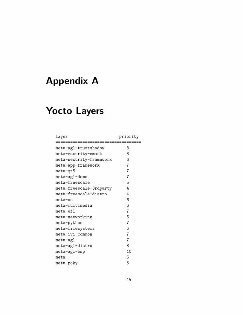
For our solution, we utilized ready-to-use Yocto project — meta-agl-demo [26] — with
2017 AGL distributive Daring Dab based on Linux kernel version 4.8. The distribu-
tive has most of AGL applications as well as UI. We created a new layer meta-agl-
trustshadow that replaces Linux kernel with our custom. Layer structure of our Yocto
project is presented in the Appendix A.
27

4.2 TrustZone Address Space Controller
TrustZone Address Space Controller (TZASC) is one of the security mechanisms that
enforces memory access control on TrustZone enabled SoCs. For the ARMv7-A mi-
croarchitecture, this mechanism is presented by the CoreLink TZC-400 Controller
(TZC-400) peripheral [27].
TZASC can be configured to protect physical static address ranges that are accessi-
ble through Static Memory Controller (SMC). These regions correspond to mapped
input/output registers (resources) of peripheral devices [27], e.g. send and receive
buffers of Ethernet interface. Up to 8 configurations can be defined and stored in
TZASC. Each configuration contains region’s base address, top address, enabled flag
and security attribute. Security attribute is effectively a 2 bit field where the first bit
controls read and second write secure global permit — if equals 1 secure operation is
permitted, otherwise not. Secure addresses can be configured during boot or runtime.
TZASC can be manipulated through set of device registers. However, it is tedious and
error prone process. That is why we decided to look for a driver, that could provide
higher level interface to the controller. Fortunately, we found a ready to use implemen-
tation in the ARM Software repository ‘arm-trusted-firmware’ [28]. The driver exposes
useful API for operating TZC, in particular, the function tzc40_configure_region()
allows to program protected memory regions, which could not be accessed by normal
world rich OS.
Hence, any peripheral device with mapped input/output resources can be secured
through TZASC, including, but not limited to, GPU, framebuffers, network card, CAN
interface, keyboard, mouse, USB ports, SD card slots, bluetooth or WiFi adapter.
Nevertheless, TZASC cannot protect itself. That is why ARM implemented TrustZone
28

Protection Controller (TZPC), which is configured only during boot and can secure a
limited number of devices with no granularity (only whole device can be accessed or
not). TZASC is protected by TZPC by default.
4.3 Secure User Interface
Secure UI is a significant component of a trusted path between user and secure world.
Secure UI implementation consists of three steps: retrieve framebuffer characteristics
and forward to secure world, protect framebuffer’s memory, setup touch logger.
Retrieving and protecting framebuffer: To retrieve framebuffer’s data we utilized
Linux fb driver which can be accessed through device file interface /dev/fb* where *
is number of a framebuffer. On our setup, main interface is rendered on fb0 which is a
background framebuffer. For secure world we used fb1 — a foreground. Framebuffer’s
characteristics are stored in kernel data structures — fb_fix_screeninfo, that con-
tains unchangeable characteristics, and fb_var_screeninfo, settings that could be
modified by user. Structures source code is presented in the Appendix B. Particular
fields of interest are:
• smem_start, smem_len — physical address of framebuffer and its size. Thisaddress range should be protected by TZASC.
• line_length — used to calculate byte location for pixel.
• xres, yres — size of screen (1024×768.)
• xoffset, yoffset — offset to visible part of framebuffer, in other words mem-ory that contains pixel values.
• bits_per_pixel — defines color depth of framebuffer, e.g. 8 bits is 256 colors,24 bits is 16.7 million.
29

After framebuffer’s characteristics were retrieved, TZ support driver sent them to secure
world through shared memory.
Low level drawing: Memory address for pixel located at (x,y) coordinates can be
calculated using the next formula [29]:
location = (x + xoffset ) * ( bits_per_pixel / 8) + (y + yoffset
) *
line_length
Now we can set any color by writing integer value that represents color in red, green,
blue format, e.g. 0xFF00FF00 will turn pixel purple with no transparency. Hence,
secure display service can draw arbitrary objects in its own secure framebuffer, which
cannot be accessed and modified by normal world OS.
Touch events: To intercept touchscreen events on Linux we utilized /dev/input/
interface that exposes all input devices presented on the system. Each device is assigned
to one or multiple event files with various numbers. Firstly, we identified which
event handler file is associated with the touchscreen by reading special Linux system
file /proc/bus/input/devices. Our touchscreen is utilizing EETI eGalax Touch
Screen driver [30] as it was the first device presented in the system file Appendix C.
Next, we established logger that continuously reads device events file, parses input
data, scales absolute touchscreen coordinates to current screen’s resolution and sends
them to TZ support driver which then forwards it to TZ display service in the secure
world. To prevent inputs flooding, e.g. during swipe or multi-touch gestures, we limited
the number of sending requests to one per 500ms. In addition, TZ support driver will
not send coordinates to secure world if secure graphics is inactive.
30

4.4 Secure Network Channel
To achieve a trusted path between secure application and cloud services all network
security related logic should be implemented in secure kernel. Our board’s Software De-
velopment Kit (SDK) did not contain any SSL/TLS library. That is why we integrated
third party library Mbed TLS [31]. Mbed TLS was primarily designed as compact
and fast SSL/TLS alternative for embedded devices. Currently is being maintained by
ARM.
Our next step was to proxy all network communications of secure application through
the secure world. This can be achieved by intercepting send() and recv() Linux
system calls, that are used to transport or receive data from the socket. Thanks to
TEE provided by TrustShadow, all system calls are being forwarded to secure monitor
before processing. Hence, we can modify the handlers of TrustShadow TEE. Each
system call has its own unique number which is stored in CPU register r7, thus we can
distinguish which system call was forwarded by checking register’s value. However, with
world switch, processor backups all registers’ values of the normal world and restores
values of the secure world. That is why we utilized global shared memory to transfer
necessary information about application’s state, including its registers’ values, before
world switch.
Finally, in system calls handlers we encrypt or decrypt payload using RSA algorithm.
In our current implementation keys are hard coded and pre-shared for simplicity sake.
In the real world scenario, secure persistent storage for certificate authorities keys is
required. This storage should be protected by TZPC to prevent any modifications by
malicious OS. In addition, an update mechanism should be implemented.
31

4.5 CAN Communication Routing
After the system’s boot, the secure world prepares CAN service. Firstly, system marks
CAN interface as secure by protecting with TZASC physical memory region where
device’s I/O registers mapped and where FlexCAN message buffers are stored. The
physical address is fixed and depends on the board’s model as well as device memory
mapping specifications. Then, system monitor starts forwarding any received CAN
messages from the normal world to CAN service.
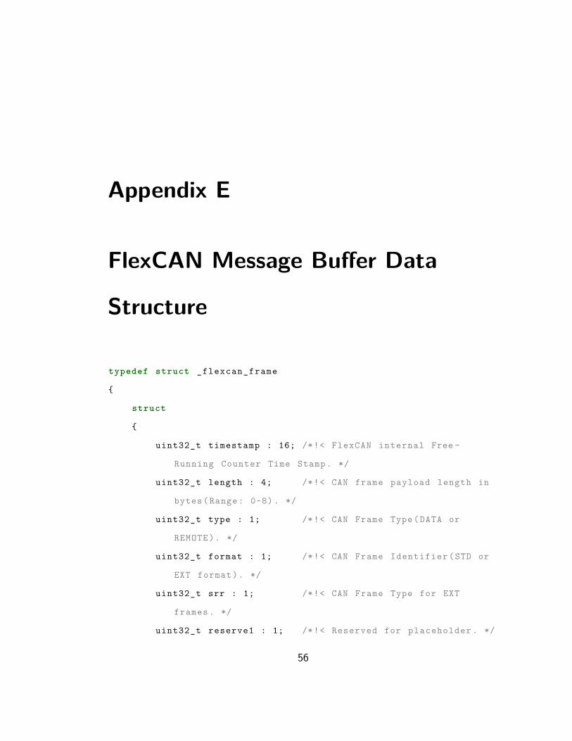
In the normal world, an application firstly assembles message buffer, following format
presented in the Appendix E, and then sends CAN message to TZ support driver.
After that, support driver places message buffer in global shared memory and initiates
a world switch. In the secure world, monitor forwards message to CAN service which
checks whether ID is allowed or not. The array of allowed identifiers is hard coded. If
the check was passed, service places the message in sending queue. It is important to
mention that we utilized FlexCAN driver, which is a part of the software development
kit for i.MX boards. The driver provides an interface and notably simplifies interaction
with the device.
In this chapter, we presented the implementation details of our security hardening
mechanisms. We described how memory regions could be protected by TZASC and how
this feature is utilized to provide the secure user interface and CAN message filtering.
In addition, we described the TrustShadow monitor and its role in the implementation
of secure network channel.
32

Chapter 5
Evaluation
In this chapter, we will demonstrate and evaluate the security characteristics of the
implemented solution.
5.1 Test Bed Overview
Our testing setup consists of 5 components.
1. i.MX6 SabreSD (MCIMX6Q-SDB) — multi-purpose development board (Fig-
ure 5.1), with 4 cores Cortex-A9 ARM processor with TrustZone support and
integrated graphics unit.
2. MCIMX LVDS1 — LVDS display with touchscreen.
3. Laptop — the board is connected to the development machine through UART
interface that gives access to the terminal of the board.
33

4. Freescale JTAG debugger — low-level hardware debugger that operates through
JTAG interface.
5. Router — both laptop and board are connected to the same router into the
network. It simplifies file exchange, allows to establish SSH sessions and enables
network booting.
Figure 5.1: i.MX6 SabreSD
AGL distributive is running on top of our configuration. Figure 5.2 shows interface of
home screen and dashboard widgets.
5.2 Features Overview and Security Evaluation
Secure UI: the feature provides the trusted path between a user and the Secure world.
For testing purpose we developed a simple scenario (Figure 5.3): user makes a purchase
34

(a) Home screen (b) Dashboard
Figure 5.2: AGL interface
from a certain application that is running inside compromised OS. We assume that the
payment module was implemented in the trusted world and properly secured. After the
application sends a transaction request to the payment module, the later one setups
confirmation dialog window with transaction details in the protected framebuffer. It
is a user’s responsibility to ensure that transaction details are correct and confirm or
deny the transaction. There are multiple possible attack scenarios for this case.
Fake Credentials: malicious OS can replace application’s payment credentials with
attacker’s. However, the transaction still should be forwarded to the secure
35

Figure 5.3: Test Scenario
world. It is the responsibility of the secure payment module to gather required
information based on receiver’s credentials and output it to the user.
Screen Overlay: malicious OS can activate the framebuffer with higher order that
overlays secure framebuffer. In our setup, we disabled all framebuffers except 0
and 1. Framebuffer 1 is foreground buffer by hardware design and always will be
drawn on top of framebuffer 0. Hence, OS cannot overlay and spoof secure UI
with malicious data.
Screen Capture: malicious OS can capture the content of secure framebuffer. This
attack is mitigated by TrustZone memory protection. Only applications inside
the secure world can read and write to protected memory regions.
Touch Events Injection: in our setup we utilized driver of the untrusted OS to
process touch events, hence, malicious OS can generate touch gestures and send
them to the secure world, thus, imitating user’s input during secure interaction
sessions. Therefore, we implemented CAPTCHA test that was described in 3.3.
CAPTCHA is generated in the secure framebuffer which malicious OS cannot
access to extract its location on the screen. Nevertheless, there is a chance
36

that attacker correctly guesses pixel coordinates and passes the test. Estimated
success rate for random guess attack on screen with 1024×768 pixels resolution
for 60 × 60 pixels sized CAPTCHA is following:
area of CAPTCHAarea of screen = 3600
786000 = 0.004 = 0.4%
Probability can be decreased by multiple orders by increasing the number of
CAPTCHA tests, however, it will reduce the usability of our solution. Confirma-
tion dialog and CAPTCHA are demonstrated in Figure 5.4.
(a) Confirmation (b) CAPTCHA
Figure 5.4: Secure UI Session
Secure Network Channel: All SSL/TLS related functionality for secure applications
37

is implemented in the secure world. Hence, a malicious OS cannot decrypt payload
(if sufficiently strong encryption algorithm has been used), cannot steal authentication
token or modify messages. In the case of impersonation attack, when an attacker tries
to impersonate a legitimate server, authenticity can be validated through a certificate
authority. However, availability of secure network channel cannot be guaranteed as
untrusted OS is responsible for network operations.
CAN Routing: In the current research, we did not conduct testing on the established
CAN network. The setup process for a CAN network is rather complex and requires
multiple CAN compatible devices, which are usually specifically manufactured for in-
dustrial and automotive systems and can be difficult to acquire. In addition, each
device should be properly configured to communicate on certain CAN protocol. Due
to time constraints, hardware limitations, and complexity of setup, we did not test
CAN routing solution. Nevertheless, we described a scenario to demonstrate how this
security mechanism prevents CAN injection attacks. CAN routing creates an additional
layer between the untrusted OS and the CAN bus. If malicious OS has direct access
to the CAN bus it can broadcast and receive any messages. Nodes cannot determine
the sender’s identity and if the received message has valid ID and format the node
will execute this command. The scenario is presented in Figure 5.5. However, IVI
does not necessarily require access to all components on the CAN bus. By applying
least-privilege principle we ensure that only allowed messages are being sent by applica-
tions from untrusted OS (Figure 5.6). It is important to note, that with this approach
attacker still can broadcast certain messages. For example, if IVI has permissions to
control HVAC ECU by design, filtering mechanism will not reject such messages.
38

Figure 5.5: CAN Bus Message Injection
Figure 5.6: CAN Bus Attack Filtered
39

Chapter 6
Conclusion
In this thesis, we have designed and implemented security hardening features for the
modern commercial automotive system, AGL, the main purpose of which is to miti-
gate attack impact in case of a compromised operating system when attacker possess
administrator’s privileges. In our approach, we utilized hardware-enforced memory iso-
lation technology, TrustZone, designed for ARM CPUs. Our solution creates a secure
execution environment for trusted applications as well as provides the mechanism to
establish secure interactive sessions between user and application. In addition, we
proposed a technique to mitigate injection of malicious messages into critical commu-
nication component of automotive systems — CAN bus. We evaluated the security
characteristics of our solution by overviewing possible attack scenarios and their coun-
termeasures implemented in the system as well as demonstrated how it helps to ensure
the confidentiality and integrity of protected components.
In future, we hope to improve compatibility with other SoC models and fully implement
CAN bus routing module by adding inspection and filtering of incoming messages.
40

Bibliography
[1] M. Wolf, A. Weimerskirch, and C. Paar. “Security in automotive bus system”. In
Workshop on Embedded Security in Cars (ESCAR), 2004.
[2] S. Checkoway, D. McCoy, B. Kantor, D. Anderson, H. Shacham, S. Savage, K.
Koscher, A. Czeskis, F. Roesner, and T. Kohno. “Comprehensive experimental
analyses of automotive attack surfaces”. In Proceedings of the 20th USENIX
Conference on Security, 2011, pp. 77–92.
[3] C. Miller and C. Valasek. “Remote exploitation of an unaltered passenger vehicle”.
In Proc. Black Hat, Las Vegas, NV, USA, 2015, pp. 1–91.
[4] M. Hamad, J. Schlatow, V. Prevelakis, and R. Ernst. “A communication frame-
work for distributed access control in microkernel-based systems”. In Operating
Sys. Platforms f. Embedded Real-Time App, 2016.
[5] A. Van Herrewege, D. Singelee, and I. Verbauwhede. “CANAuth - a simple, back-
ward compatible broadcast authentication protocol for CAN bus”. In ECRYPT
Workshop on Lightweight Cryptography, 2011.
[6] L. Guan, P. Liu, X. Xing, X. Ge, S. Zhang, M. Yu, and T. Jaeger. “Trust-
Shadow: secure execution of unmodified applications with ARM TrustZone”. In
41

Proceedings of the 15th Annual International Conference on Mobile Systems,
Applications, and Services, Niagara Falls, NY, USA, 2017.
[7] Alex Wright. “Hacking cars”. In Communications of the Acm 54.11 (Nov. 2011).
[8] D. Eckhoff and C. Sommer. “Driving for big data? Privacy concerns in vehicular
networking”. In IEEE Security and Privacy 12.1 (Jan. 2014), pp. 77–79.
[9] M. Whalen, D. Cofer, and A. Gacek. “Requirements and architectures for secure
vehicles”. In IEEE Software 33.4 (June 2016), pp. 22–25.
[10] W. Gao and T. Morris. “On cyber attacks and signature based intrusion detection
for Modbus based industrial control systems”. In Journal of Digital Forensics,
Security and Law 9.1 (2014), pp. 37–56.
[11] J. Osborn and D. Challener. “Trusted platform module evolution”. In Johns Hop-
kins APL Technical Digest 32.2 (2013), pp. 536–543.
[12] N. Asokan, J. Ekberg, and K. Kostiainen. “The untapped potential of trusted
execution environments on mobile devices”. In International Conference on Fi-
nancial Cryptography and Data Security, Okinawa, Japan, 2013.
[13] A. Wool. “The use and usability of direction-based filtering in firewalls”. In Com-
puters and Security 23 (2004), pp. 459–468.
[14] J. Osborn and D. Challener. “Data exfiltration: A review of external attack vec-
tors and countermeasures”. In Journal of Network and Computer Applications
101 (Nov. 2017), pp. 18–54.
[15] B. Lampson, M. Abadi, M. Burrows, and E. Wobber. “Authentication in dis-
tributed systems: theory and practice”. In ACM Transactions on Computer Sys-
tems 10.4 (Nov. 1992), pp. 265–310.
42

[16] J. Saltzer and M. Schroeder. “The protection of information in computer sys-
tems”. In Communications of the ACM 17.7 (July 1974).
[17] ARM Security Technology. url: http://infocenter.arm.com/help/topic/
com.arm.doc.prd29-genc-009492c/PRD29-GENC-009492C_trustzone_
security_whitepaper.pdf (visited on 09/15/2018).
[18] Automotive Grade Linux Platform Debuts on the 2018 Toyota Camry. url: ht
tps://www.automotivelinux.org/announcements/2017/05/30/automot
ive-grade-linux-platform-debuts-on-the-2018-toyota-camry (visited
on 09/15/2018).
[19] Freescale Semiconductor. NXP Semiconductors | Automotive, Security, IoT.
url: https://www.nxp.com/ (visited on 11/30/2018).
[20] Steve Corrigan. Introduction to the Controller Area Network (CAN). url: http:
//www.ti.com/lit/an/sloa101b/sloa101b.pdf (visited on 10/15/2018).
[21] CAN lower- and higher-layer protocols. url: https://www.can-cia.org/can-
knowledge (visited on 10/15/2018).
[22] Standard for Connecting Electric Components of Light Electric Vehicles. url: h
ttp://www.energybus.org (visited on 11/30/2018).
[23] MilCAN. url: https://www.milcan.org (visited on 11/30/2018).
[24] David Paterson. MPC5510 New FlexCAN Module Features. url: https://www.
nxp.com/docs/en/application-note/AN3488.pdf (visited on 10/31/2018).
[25] Linux community. The Yocto Project. url: https://www.yoctoproject.org/
(visited on 10/25/2018).
43

[26] AGL community. AGL Developer Site - meta-agl-demo. url: http://docs.
automotivelinux.org/docs/devguides/en/dev/reference/meta-agl-
demo.html (visited on 10/25/2018).
[27] Genode Labs. An Exploration of ARM TrustZone Technology. url: https://
genode.org/documentation/articles/trustzone (visited on 10/31/2018).
[28] ARM Software. TZC-400 Implementation. url: https://github.com/ARM-s
oftware/arm-trusted-firmware/tree/master/drivers/arm/tzc (visited
on 10/31/2018).
[29] Philip Prushik. Low-Level Graphics on Linux. url: http://betteros.org/
tut/graphics1.php (visited on 11/03/2018).
[30] i.MX 6 Board. url: https://www.nxp.com/support/developer-resources
(visited on 11/30/2018).
[31] ARM. An open source, portable, easy to use, readable and flexible SSL library.
url: https://github.com/ARMmbed/mbedtls (visited on 11/03/2018).
[32] ARM. ARM CoreLink TZC-400 TrustZone Address Space Controller. url: http:
//infocenter.arm.com/help/topic/com.arm.doc.ddi0504c/DDI0504C_
tzc400_r0p1_trm.pdf (visited on 10/31/2018).
44
Appendix A
Yocto Layers
layer priority===================================meta-agl-trustshadow 8meta-security-smack 8meta-security-framework 6meta-app-framework 7meta-qt5 7meta-agl-demo 7meta-freescale 5meta-freescale-3rdparty 4meta-freescale-distro 4meta-oe 6meta-multimedia 6meta-efl 7meta-networking 5meta-python 7meta-filesystems 6meta-ivi-common 7meta-agl 7meta-agl-distro 8meta-agl-bsp 10meta 5meta-poky 5
45

Appendix B
Framebuffer Structures
// dump from include /uapi/linux /fb.h
struct fb_fix_screeninfo {
char id [16]; /* identification string eg "TT Builtin " */
unsigned long smem_start ; /* Start of frame buffer mem */
/* ( physical address ) */
__u32 smem_len ; /* Length of frame buffer mem */
__u32 type; /* see FB_TYPE_ * */
__u32 type_aux ; /* Interleave for interleaved Planes */
__u32 visual ; /* see FB_VISUAL_ * */
__u16 xpanstep ; /* zero if no hardware panning */
__u16 ypanstep ; /* zero if no hardware panning */
__u16 ywrapstep ; /* zero if no hardware ywrap */
__u32 line_length ; /* length of a line in bytes */
unsigned long mmio_start ; /* Start of Memory Mapped I/O */
/* ( physical address ) */
__u32 mmio_len ; /* Length of Memory Mapped I/O */
__u32 accel ; /* Indicate to driver which */
46

/* specific chip/card we have */
__u16 capabilities ; /* see FB_CAP_ * */
__u16 reserved [2]; /* Reserved for future compatibility */
};
struct fb_var_screeninfo {
__u32 xres; /* visible resolution */
__u32 yres;
__u32 xres_virtual ; /* virtual resolution */
__u32 yres_virtual ;
__u32 xoffset ; /* offset from virtual to visible */
__u32 yoffset ; /* resolution */
__u32 bits_per_pixel ; /* guess what */
__u32 grayscale ; /* 0 = color , 1 = grayscale , */
/* >1 = FOURCC */
struct fb_bitfield red; /* bitfield in fb mem if true
color , */
struct fb_bitfield green ; /* else only length is
significant */
struct fb_bitfield blue;
struct fb_bitfield transp ; /* transparency */
__u32 nonstd ; /* != 0 Non standard pixel format */
__u32 activate ; /* see FB_ACTIVATE_ * */
__u32 height ; /* height of picture in mm */
__u32 width ; /* width of picture in mm */
47

__u32 accel_flags ; /* ( OBSOLETE ) see fb_info .flags */
/* Timing : All values in pixclocks , except pixclock (of course )
*/
__u32 pixclock ; /* pixel clock in ps (pico seconds ) */
__u32 left_margin ; /* time from sync to picture */
__u32 right_margin ; /* time from picture to sync */
__u32 upper_margin ; /* time from sync to picture */
__u32 lower_margin ;
__u32 hsync_len ; /* length of horizontal sync */
__u32 vsync_len ; /* length of vertical sync */
__u32 sync; /* see FB_SYNC_ * */
__u32 vmode ; /* see FB_VMODE_ * */
__u32 rotate ; /* angle we rotate counter clockwise */
__u32 colorspace ; /* colorspace for FOURCC -based modes */
__u32 reserved [4]; /* Reserved for future compatibility */
};
48

Appendix C
Input Devices
I: Bus=0018 Vendor=0000 Product=0000 Version=0000
N: Name="EETI eGalax Touch Screen"
P: Phys=
U: Uniq=
H: Handlers=mouse0 event0
B: PROP=0
B: EV=b
B: KEY=400 0 0 0 0 0 0 0 0 0 0
B: ABS=2608000 3
I: Bus=0018 Vendor=0000 Product=0000 Version=0000
N: Name="max11801_ts"
P: Phys=
U: Uniq=
49

H: Handlers=mouse1 event1
B: PROP=0
B: EV=b
B: KEY=400 0 0 0 0 0 0 0 0 0 0
B: ABS=3
I: Bus=0018 Vendor=0000 Product=0000 Version=0000
N: Name="mag3110"
P: Phys=
S: Sysfs=/devices/virtual/input/input3
U: Uniq=
H: Handlers=event2
B: PROP=0
B: EV=9
B: ABS=7
I: Bus=0018 Vendor=0000 Product=0000 Version=0000
N: Name="mma845x"
P: Phys=
S: Sysfs=/devices/virtual/input/input4
U: Uniq=
H: Handlers=event3
B: PROP=0
B: EV=9
B: ABS=7
50

I: Bus=0018 Vendor=0000 Product=0000 Version=0000
N: Name="WM8962 Beep Generator"
P: Phys=0-001a
U: Uniq=
H: Handlers=kbd event4
B: PROP=0
B: EV=40001
B: SND=6
I: Bus=0019 Vendor=0001 Product=0001 Version=0100
N: Name="gpio-keys"
P: Phys=gpio-keys/input0
S: Sysfs=/devices/soc0/gpio-keys/input/input8
U: Uniq=
H: Handlers=kbd event5
B: PROP=0
B: EV=3
B: KEY=1c0000 0 0 0
51

Appendix D
Touch Logger
# include <stdio.h>
# include <stdlib .h>
# include <unistd .h>
# include <fcntl.h>
# include <linux/input.h>
# define EVENT_DEVICE "/dev/input / event0 "
# define EVENT_TYPE EV_ABS
# define EVENT_CODE_X ABS_X
# define EVENT_CODE_Y ABS_Y
# define EGALAX_MAX_X 32760
# define EGALAX_MAX_Y 32760
# define XRES 1024
# define YRES 768
int main(int argc , char *argv [])
{
52

const size_t ev_size = sizeof ( struct input_event );
struct input_event ev;
int fd;
float xscale = ( float ) XRES / EGALAX_MAX_X ;
float yscale = ( float ) YRES / EGALAX_MAX_Y ;
char name [256];
if ( getuid () != 0)
{
fprintf (stderr , "Root required !\n");
return EXIT_FAILURE ;
}
/* Open Device */
fd = open( EVENT_DEVICE , O_RDONLY );
if (fd == -1)
{
fprintf (stderr , "%s is not a vaild device \n", EVENT_DEVICE
);
return EXIT_FAILURE ;
}
/* Print Device Info */
ioctl (fd , EVIOCGNAME ( sizeof (name)), name);
printf (" Reading from :\n");
printf (" device file = %s\n", EVENT_DEVICE );
printf (" device name = %s\n", name);
printf (" scale factor x:%f y:%f\n", xscale , yscale );
while (1)
53

{
ssize_t size;
size = read(fd , &ev , ev_size );
if (size < ev_size )
{
fprintf (stderr , " Device read error \n");
goto err;
}
/* Print coordinates */
if (ev.type == EVENT_TYPE )
{
char evname ;
if(ev.code == EVENT_CODE_X )
{
ev.value = xscale * ev.value ;
evname = ’X’;
}
else if(ev.code == EVENT_CODE_Y )
{
ev.value = yscale * ev.value ;
evname = ’Y’;
}
else
continue ;
printf ("%d: %c = %d\n", ev.code , evname , ev. value );
}
}
return EXIT_SUCCESS ;
54

err:
close (fd);
return EXIT_FAILURE ;
}
55
Appendix E
FlexCAN Message Buffer Data
Structure
typedef struct _flexcan_frame
{
struct
{
uint32_t timestamp : 16; /*!< FlexCAN internal Free -
Running Counter Time Stamp . */
uint32_t length : 4; /*!< CAN frame payload length in
bytes (Range : 0~8). */
uint32_t type : 1; /*!< CAN Frame Type(DATA or
REMOTE ). */
uint32_t format : 1; /*!< CAN Frame Identifier (STD or
EXT format ). */
uint32_t srr : 1; /*!< CAN Frame Type for EXT
frames . */
uint32_t reserve1 : 1; /*!< Reserved for placeholder . */
56

uint32_t code : 4; /*!< Status code. */
uint32_t reserve4 : 4; /*!< Reserved for placeholder . */
};
struct
{
uint32_t id : 29; /*!< CAN Frame Identifier , should be set
using FLEXCAN_ID_EXT () or FLEXCAN_ID_STD () macro . */
uint32_t prio : 3; /*!< Local priority . */
};
struct
{
uint8_t dataByte3 ; /*!< CAN Frame payload byte3. */
uint8_t dataByte2 ; /*!< CAN Frame payload byte2. */
uint8_t dataByte1 ; /*!< CAN Frame payload byte1. */
uint8_t dataByte0 ; /*!< CAN Frame payload byte0. */
uint8_t dataByte7 ; /*!< CAN Frame payload byte7. */
uint8_t dataByte6 ; /*!< CAN Frame payload byte6. */
uint8_t dataByte5 ; /*!< CAN Frame payload byte5. */
uint8_t dataByte4 ; /*!< CAN Frame payload byte4. */
};
} flexcan_frame_t ;
57