Embed Size (px)
Citation preview
IEEE SENSORS JOURNAL, VOL. 21, NO. 7, APRIL 1, 2021 8903
Towards a Wireless Force Sensor Based onWave Backscattering for Medical ApplicationsCédric Girerd , Qiming Zhang, Agrim Gupta, Manideep Dunna , Dinesh Bharadia, Member, IEEE,
and Tania. K. Morimoto , Member, IEEE
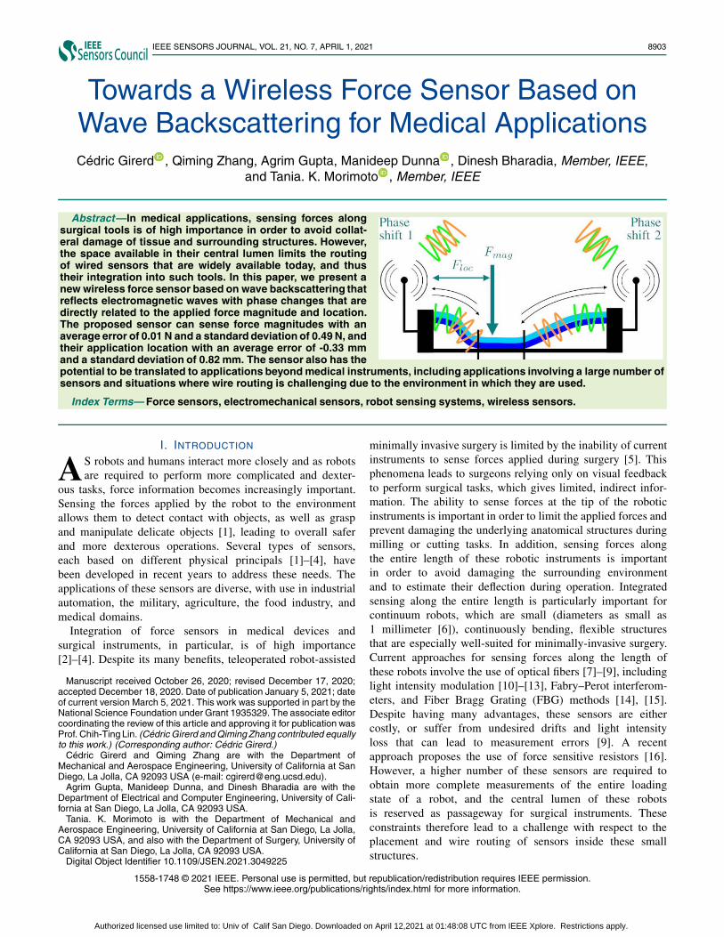
Abstract—In medical applications, sensing forces alongsurgical tools is of high importance in order to avoid collat-eral damage of tissue and surrounding structures. However,the space available in their central lumen limits the routingof wired sensors that are widely available today, and thustheir integration into such tools. In this paper, we present anew wireless force sensor based on wave backscattering thatreflects electromagnetic waves with phase changes that aredirectly related to the applied force magnitude and location.The proposed sensor can sense force magnitudes with anaverage error of 0.01 N and a standard deviation of 0.49 N, andtheir application location with an average error of -0.33 mmand a standard deviation of 0.82 mm. The sensor also has thepotential to be translated to applications beyond medical instruments, including applications involving a large number ofsensors and situations where wire routing is challenging due to the environment in which they are used.
Index Terms— Force sensors, electromechanical sensors, robot sensing systems, wireless sensors.
I. INTRODUCTION
AS robots and humans interact more closely and as robotsare required to perform more complicated and dexter-
ous tasks, force information becomes increasingly important.Sensing the forces applied by the robot to the environmentallows them to detect contact with objects, as well as graspand manipulate delicate objects [1], leading to overall saferand more dexterous operations. Several types of sensors,each based on different physical principals [1]–[4], havebeen developed in recent years to address these needs. Theapplications of these sensors are diverse, with use in industrialautomation, the military, agriculture, the food industry, andmedical domains.
Integration of force sensors in medical devices andsurgical instruments, in particular, is of high importance[2]–[4]. Despite its many benefits, teleoperated robot-assisted
Manuscript received October 26, 2020; revised December 17, 2020;accepted December 18, 2020. Date of publication January 5, 2021; dateof current version March 5, 2021. This work was supported in part by theNational Science Foundation under Grant 1935329. The associate editorcoordinating the review of this article and approving it for publication wasProf. Chih-Ting Lin. (Cédric Girerd and Qiming Zhang contributed equallyto this work.) (Corresponding author: Cédric Girerd.)
Cédric Girerd and Qiming Zhang are with the Department ofMechanical and Aerospace Engineering, University of California at SanDiego, La Jolla, CA 92093 USA (e-mail: [email protected]).
Agrim Gupta, Manideep Dunna, and Dinesh Bharadia are with theDepartment of Electrical and Computer Engineering, University of Cali-fornia at San Diego, La Jolla, CA 92093 USA.
Tania. K. Morimoto is with the Department of Mechanical andAerospace Engineering, University of California at San Diego, La Jolla,CA 92093 USA, and also with the Department of Surgery, University ofCalifornia at San Diego, La Jolla, CA 92093 USA.
Digital Object Identifier 10.1109/JSEN.2021.3049225
minimally invasive surgery is limited by the inability of currentinstruments to sense forces applied during surgery [5]. Thisphenomena leads to surgeons relying only on visual feedbackto perform surgical tasks, which gives limited, indirect infor-mation. The ability to sense forces at the tip of the roboticinstruments is important in order to limit the applied forces andprevent damaging the underlying anatomical structures duringmilling or cutting tasks. In addition, sensing forces alongthe entire length of these robotic instruments is importantin order to avoid damaging the surrounding environmentand to estimate their deflection during operation. Integratedsensing along the entire length is particularly important forcontinuum robots, which are small (diameters as small as1 millimeter [6]), continuously bending, flexible structuresthat are especially well-suited for minimally-invasive surgery.Current approaches for sensing forces along the length ofthese robots involve the use of optical fibers [7]–[9], includinglight intensity modulation [10]–[13], Fabry–Perot interferom-eters, and Fiber Bragg Grating (FBG) methods [14], [15].Despite having many advantages, these sensors are eithercostly, or suffer from undesired drifts and light intensityloss that can lead to measurement errors [9]. A recentapproach proposes the use of force sensitive resistors [16].However, a higher number of these sensors are required toobtain more complete measurements of the entire loadingstate of a robot, and the central lumen of these robotsis reserved as passageway for surgical instruments. Theseconstraints therefore lead to a challenge with respect to theplacement and wire routing of sensors inside these smallstructures.
1558-1748 © 2021 IEEE. Personal use is permitted, but republication/redistribution requires IEEE permission.See https://www.ieee.org/publications/rights/index.html for more information.
Authorized licensed use limited to: Univ of Calif San Diego. Downloaded on April 12,2021 at 01:48:08 UTC from IEEE Xplore. Restrictions apply.
8904 IEEE SENSORS JOURNAL, VOL. 21, NO. 7, APRIL 1, 2021
A. Force Sensor TechnologiesForce sensors to date have used a variety of different
physical principals, and generally take the form of transducers,by converting the mechanical energy of a physical contact toan electrical signal [3]. The main types of sensors commer-cially available today include force sensitive resistors [16],piezoelectric [17], capacitive, inductive, optical [8], [13], ultra-sonic, magnetic, electromagnetic (EM) tracking systems andelectrical impedance tomography sensors. Some sensors alsoimplement a combination of physical principals to overcometheir individual limitations [2].
While these sensors may vary in terms of both workingmechanism and in terms of performance, they all provide aninput that is not suitable for direct wireless communication,and therefore require additional electronics to encode theiroutputs in a suitable format [18]. This requirement typicallyleads to an increase in the size of these sensors, which is notsuitable for integration with small robotic instruments or withuse in constrained environments. In addition, these sensorsneed to be powered electrically or need a light source, leadingto the need for physical connections between the sensor andan external base. The requirement of maintaining a physicalconnection poses a wire routing issue when the sensors aremounted on remote structures, when a large number of sensorsare used, or when the sensors are located in confined spaces.
A few examples of wireless force sensors are proposedin the literature, including LC resonant circuits [19] andstrain sensors based on electromagnetically soft materials [20].However, LC resonant circuits require a close interrogationdistance between the sensor and the readout circuits – onthe order of magnitude of a centimeter – and are accompa-nied with issues due to misalignment, noise from the envi-ronment, and cross-talking among elements [21]. Similarly,the wireless force sensors based on electromagnetically softmaterials require multiple large coils in close proximity to thesensor [20], which is not practical for most applications inconfined spaces.
B. Integrating Sensing With Wave BackscatteringWave backscaterring systems differ from conventional com-
munication systems. Rather than actively generating a wirelesssignal from a source of energy to communicate, they simplyreflect ambient signals sent by transmitting antennas. Theproperties of the signal traveling through the backscatter-ing system, including phase [22], amplitude [23], and fre-quency [24], encode the information to be communicated. Thereflected signal is then measured by receiving antennas.
To date, a few groups have used wave backscattering tosense binary contact information (i.e. contact or no con-tact) [22]–[29]. IDSense [23] used a combination of ampli-tude and phase changes to detect contact information with abackscaterring RFID tag, and PaperId [29] showed a simplemanufacturing method to print these RFID tags using an inkjetprinter and paper. RIO [22] showed how to sense contact onmultiple tags by using phase changes due to mutual couplingof the tags. LiveTag [24] further extended this contact sensingto be performed via WiFi access points instead of dedicatedRFID readers as used by previous work. Although these
backscatter-based sensors are very simple in their structure andeasy to manufacture, they are limited to binary measurementsof contact/no-contact, and analog force sensing has yet to beproposed in this context.
There has been one recent example of a type ofbackscatter-based sensor, known as a SAW (Surface AcousticWaves) based strain sensor, that aims to sense analog forces.These passive strain sensors [30]–[33] encode the strain infor-mation in terms of resonance frequency shifts in the backscat-tered signal. The strain readings are then inferred at thereceiver by estimating the amplitudes at multiple frequenciesto detect the frequency shift. However, most of the worksshow evaluations in a controlled, anechoic environment, andthe technology has not been found to be robust to staticmultipath [31].
C. ContributionsIn this paper, we present a new wireless force sensor capable
of detecting both the magnitude and location of an appliedforce. It differs from the existing sensor technologies in itsintegrated wireless capability that does not require the use ofadditional electronics for conversion of force information intoa suitable format for wireless communication. It is based onthe wave backscattering principal, and the developed prototypeconsists of three main components: (i) a mechanical beamthat when pressed into a rigid base, results in a contactwith edge locations that depend on the force magnitude andits application location, (ii) a signal and ground trace thatcover the mechanical beam and rigid base, respectively, andconvert the mechanical contact into an electrical contact, and(iii) antennas that are connected to these traces. The antennasreceive electromagnetic waves that propagate inside the signaltrace, get reflected at the shorting location between the signaland ground traces, and are re-emitted passively by the sensor,thus following a backscattering principal, with phase shiftsthat depend on both the magnitude and location of the forceapplied.
The paper is organized as follows: Section II details theconcept of the sensor. Design rules are then presented inSections III and IV for the mechanical transducer and theelectrical trace, respectively. The wireless sensing algorithm isthen presented in Section V. An implementation of the sensorbased on design specifications is presented in Section VI, andassessment of mechanical, wired, and wireless performanceof the sensor are presented in Section VII. Conclusions andperspectives are finally presented in Section VIII.
II. PROPOSED CONCEPT
In this section, the sensor architecture and working principleare presented.
A. Sensor ConceptThe proposed sensor is based on the principle of electro-
magnetic wave backscattering. It consists of a wireless readerthat emits an electromagnetic wave. When this wave reachesthe proposed sensor, it travels along an electrical trace fromboth ends of the sensor, is reflected back at shorting locationswith a ground trace, and thus travels back along the direction
Authorized licensed use limited to: Univ of Calif San Diego. Downloaded on April 12,2021 at 01:48:08 UTC from IEEE Xplore. Restrictions apply.
GIRERD et al.: TOWARDS WIRELESS FORCE SENSOR FOR MEDICAL APPLICATIONS 8905
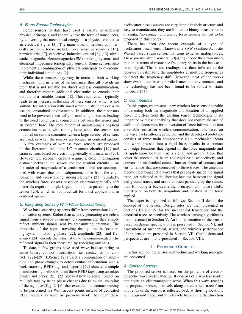
Fig. 1. Illustration of the sensor, which is composed of a bilayer beam(in light and dark blue) and a rigid base (in black). The edges of thecontact length between these two components are denoted xcont1 andxcont2. These components are also covered by contact traces thatcarry electromagnetic waves, shown in green and orange, through twoantennas located at both ends of the sensor. These phases, denotedφ1 and φ2 after reflection, are measured by the reader and used todetermine the applied force magnitude (Fmag) and location (Floc).
from which it came. This reflected wave is then detected bythe wireless reader, as illustrated in Fig. 1. We propose asensor that induces changes in the total distance traveled bytwo reflected electromagnetic waves when a force is applied.We propose to measure the changes in the distances traveledby measuring the associated phase changes of the reflectedwaves. Knowing the relationship between the force magnitude,the location of this applied force, and the phase changesmeasured, the device becomes a force sensor, able to detectboth the magnitude and application location of a force.
B. Sensor OverviewThe sensor is composed of three main components. The first
component is a mechanical transducer, able to deform uniquelyupon application of a force magnitude and application location.For this component, we propose to used a fixed-ended bilayerbeam, with the layers represented in light and dark blue inFig. 1. Upon application of a force, this beam is pressedinto contact with a rigid base, represented in black in Fig. 1.The edges of the corresponding contact length are denotedxcont1 and xcont2 (see Fig. 1). The top layer of the bilayerbeam is stiffer than the bottom layer, such that the appliedforce is distributed onto the softer bottom layer, leading to anincreasing contact length with the rigid base as the appliedforce is increased. The location of the contact edges betweenthe bilayer beam and the rigid base informs us of the forcemagnitude and its application location.
The second component of the sensor consists of two electri-cal traces that cover the bottom side of the bilayer beam andthe top side of the rigid base. The trace covering the bilayerbeam is the signal trace, while the one covering the rigid baseis the ground trace. The signal trace converts the mechanicalcontact locations xcont1 and xcont2 between the bilayer beamand the rigid base into electrical shorting locations whenit touches the ground trace. This phenomena leads to thereflection of the emitted electromagnetic waves at the shortinglocations, as visible in Fig. 1.
TABLE INOMENCLATURE
The last component is the wireless hardware and associatedalgorithm that senses the phases φ1 and φ2 of the signalsthat are reflected at the shorting locations on the signaltrace (see Fig. 1). In order for the reader to distinguish thesignal reflected by the sensor and the one initially sent to it,RF switches are used on both ends of the sensor to module thereflected signal before it is re-emitted by the sensor, as visiblein Fig 1. These three main components are presented in thefollowing sections, and the main associated variables used arevisible in Table I.
III. MECHANICAL TRANSDUCER DESIGNIn this section, we present a design method for the mechan-
ical transducer of the sensor. The method is split into twoparts based on the stages of deflection of the bilayer beam.The first part involves multilayer beam mechanics to describethe behavior of the sensor at initial contact with the rigid base,while the second part involves FEA (finite element analysis) todescribe the behavior of the sensor after initial contact, whenthe bilayer beam is pressed against the rigid base.
A. Beam Deflection at Initial Contact1) Bilayer Beam Bending Stiffness: In order to describe
the behavior of the bilayer beam and its deflection uponapplication of a force, its equivalent bending stiffness must firstbe expressed. For this, we use multilayer beam mechanics [34].The equivalent bending stiffness D of a beam composed of nlayers is given by Eq. (1), where Ei is the Young’s modulusof the i -th layer, and Ii is its moment of inertia.
D =n�
i=1
Ei Ii , (1)
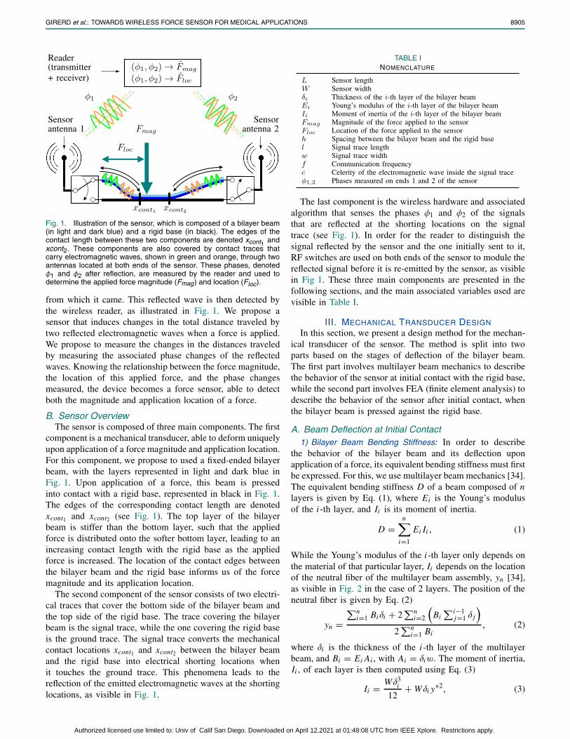
While the Young’s modulus of the i -th layer only depends onthe material of that particular layer, Ii depends on the locationof the neutral fiber of the multilayer beam assembly, yn [34],as visible in Fig. 2 in the case of 2 layers. The position of theneutral fiber is given by Eq. (2)
yn =�n
i=1 Biδi + 2�n
i=2
�Bi
�i−1j=1 δ j
�2
�ni=1 Bi
, (2)
where δi is the thickness of the i -th layer of the multilayerbeam, and Bi = Ei Ai , with Ai = δiw. The moment of inertia,Ii , of each layer is then computed using Eq. (3)
Ii = Wδ3i
12+ Wδi y∗2, (3)
Authorized licensed use limited to: Univ of Calif San Diego. Downloaded on April 12,2021 at 01:48:08 UTC from IEEE Xplore. Restrictions apply.
8906 IEEE SENSORS JOURNAL, VOL. 21, NO. 7, APRIL 1, 2021
Fig. 2. Schematic of a multilayer beam in the case of two layers, withthe dimensions of its cross-section and the position of the neutral fiberyn along the y-axis.
with
y∗ = yn − 0.5δi −i−1�m=1
δm . (4)
In the case of a beam composed of two layers (i.e. a bilayerbeam), as is the case for our application, the bendingstiffness, D, given by Eq. 1, reduces to Eq. 5.
D
=W
�E2
1δ41 +4E1E2δ
31δ2+6E1E2δ
21δ2
2 +4E1E2δ1δ32 +E2
2δ42
I2(E1δ1 + E2δ2)
�
(5)
2) Bilayer Beam Mechanics Model: In order to use the equa-tions from beam mechanics, we assume that the beam satisfiesEuler-Bernoulli’s hypothesis. The hypothesis is satisfied ifEq. (6) holds, where E is the Young’s modulus of the beam, Iits cross-sectional moment of inertia, κ the Timoshenko shearcoefficient, L the beam length, A its cross-sectional area, andG its shear modulus. In the case of a beam with a rectangularcross-section, κ = 5/6. For a bilayer beam, we assess thevalidity of Eq. (6) in the extreme case where the beam iscomprised of two layers made (i) solely of material 1 and(ii) solely of material 2, which is sufficient to validate thehypothesis and covers all thickness ratios between these twoextremes.
E I
κ L2 AG� 1 (6)
The deflection y(x) of the bilayer beam subject to a point forceis obtained by expressing the moment balance Mz(x) along thebilayer beam in the regions x ∈ [0, Floc] and x ∈ [Floc, L]and calculating d2 y(x)
dx2 = Mz(x)D , and leads to the expressions
in Eq. (7):
y(x) =
⎧⎪⎪⎪⎪⎪⎪⎪⎨⎪⎪⎪⎪⎪⎪⎪⎩
Fmag x2(L − Floc)2(Lx − 3L Floc + 2Flocx)
6DL3
if x ∈ [0, Floc]
Fmag F2loc(L − x)2(L Floc − 3Lx + 2Flocx)
6DL3
if x ∈ [Floc, L],
(7)
with D the bending stiffness of the bilayer beam, given byEq. (1). The maximum deflection ymax of the bilayer beam,
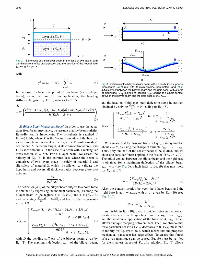
Fig. 3. Scheme of the bilayer sensor beam with double built-in supports,represented (a) at rest with its main physical parameters, and (b) atinitial contact between the bilayer beam and the rigid base, with a forceof magnitude Fmag exerted at location Floc, leading to a single contactbetween the bilayer beam and the rigid base at x = xcont.
and the location of this maximum deflection along it, are thenobtained by solving dy(x)
dx = 0, leading to Eq. (8).
ymax =
⎧⎪⎪⎪⎪⎪⎪⎪⎪⎨⎪⎪⎪⎪⎪⎪⎪⎪⎩
2Fmag F2loc(L − Floc)
3
3D(3L − 2Floc)2 at x = L2
3L − 2Flocif Floc ≤ L/2
2Fmag F3loc(L − Floc)
2
3D(L + 2Floc)2 at x = 2L Floc
L + 2Flocif Floc ≥ L/2
(8)
We can see that the two solutions in Eq. (8) are symmetricabout x = L
2 , by using the change of variable Floc → L−Floc.Thus, only one half of the sensor needs to be studied, and wechoose to consider forces applied to the first half (Floc ≤ L/2).The initial contact between the bilayer beam and the rigid baseis obtained for a maximum deflection of the bilayer beamymax = h (see Fig. 3), which leads to Eq. (9) that must holdfor Floc ≤ L/2.
h = 2Fmag F2loc(L − Floc)
3
3D(3L − 2Floc)2 (9)
Also, the contact location between the bilayer beam and therigid base is at x = xcont , with xcont given by Eq. (10) (seeFig. 3(b)).
xcont = L2
3L − 2Floc(10)
As visible in Eq. (10), there is unicity between the contactlocation between the bilayer beam and the rigid base, xcont,and the location of application of the force on it, Floc, whichallows a unique mapping between them. Then, we observe thatfor a particular sensor, as Floc decreases to 0, Fmag must tendto infinity for Eq. (9) to hold, which means that the proposedmechanical transducer has edge effects. To ensure that forcesof a given magnitude can be sensed, Eq. (9) must be verifiedfor the smallest values of Floc. In addition, Eq. (9) allows
Authorized licensed use limited to: Univ of Calif San Diego. Downloaded on April 12,2021 at 01:48:08 UTC from IEEE Xplore. Restrictions apply.
GIRERD et al.: TOWARDS WIRELESS FORCE SENSOR FOR MEDICAL APPLICATIONS 8907
Fig. 4. Scheme of the bilayer sensor beam with double built-in supportsafter initial contact, when a force of Fmag is applied at location Floc. Theedges of the contact locations are denoted xcont1 and xcont2 .
us to define a relationship between the minimum force thatcan be sensed by the sensor and all of its mechanical designparameters, which is suitable for design optimization purposes.Indeed, the bilayer beam deflection for initial contact, h, is anincreasing function of L and a decreasing function of D,and therefore a decreasing function of W , E1, E2, δ1, δ2.By adjusting these design variables, desired performance canbe obtained in terms of the minimum force that can be detectedalong the sensor length.
B. Beam Deformation After Initial ContactAfter initial contact, as both beams are pressed against
each other, beam mechanics is no longer applicable, and finiteelement analysis is thus used to model the contact betweenthem. FEA is used to compute the location of the contactedges xcont1 and xcont2 between the bilayer beam and therigid base, as illustrated in Fig. 4. An increase in appliedforce corresponds to an increase in contact length betweenthe beams around the initial contact point predicted by thebilayer beam mechanics model. A critical requirement for thesensor is that the displacement of these contact edges shouldlead to significant phase changes that are measurable andprovide sufficient force magnitude and application locationresolution. The contact edge location requirements are thusdictated by the next sections on the trace design and wirelessphase measurement approach. They will lead to the selectionof the design parameters L, w, E1, E2, δ1, δ2 and h of thesensor that, while respecting Eq. (8), will allow us to obtainthe desired contact edges between the bilayer beam and therigid base.
IV. ELECTRICAL TRACE DESIGN
In this section, we present the design rules that dictate thegeometry of the signal trace of the sensor, which is used toconvert the mechanical contact between the beams into phasechanges of the electromagnetic waves that travel along it. Thecase of a rectilinear signal trace, which connects both ends ofthe sensor along a straight line, is considered in this work.
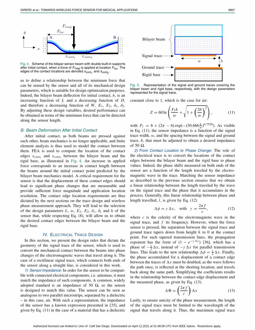
1) Sensor Impedance: In order for the sensor to be compati-ble with connected electrical components, i.e. antennas, it mustmatch the impedance of such components. A common, widelyadopted standard is an impedance of 50 �, so the sensoris designed to match this value. The sensor can be seen asanalogous to two parallel microstrips, separated by a dielectric– in this case, air. With such a representation, the impedanceof the sensor has a known expression presented in [35], andgiven by Eq. (11) in the case of a material that has a dielectric
Fig. 5. Representation of the signal and ground traces covering thebilayer beam and rigid base, respectively, with the design parametersrepresented for the signal trace.
constant close to 1, which is the case for air:
Z = 60 ln
⎛⎝ F1h
w+
�1 +
�2h
w
�2⎞⎠ , (11)
with F1 = 6 + (2π − 6) exp(−(30.666 hw)0.7528). As visible
in Eq. (11), the sensor impedance is a function of the signaltrace width, w, and the spacing between the signal and groundtrace, h, that must be adjusted to obtain a desired impedanceof 50 �.
2) From Contact Location to Phase Change: The role ofthe electrical trace is to convert the locations of the contactedges between the bilayer beam and the rigid base to phasevalues. Indeed, the phase shifts measured on both ends of thesensor are a function of the length traveled by the electro-magnetic wave in the trace. Matching the sensor impedanceas described in the previous section ensures that we obtaina linear relationship between the length traveled by the waveon the signal trace and the phase that it accumulates in theprocess. Generally, this linear relationship between phase andlength travelled, l, is given by Eq. (12)
�φ = γ�x, with γ = 2π f
c, (12)
where c is the celerity of the electromagnetic wave in thesignal trace, and f its frequency. However, when the forcesensor is pressed, the separation between the signal trace andground trace tapers down from height h to 0 at the contactpoint. For such tapered transmission lines, the propagationexponent has the form of (1 − e−γ�x) [36], which has aphase of − γ
2 �x , instead of −γ�x for parallel transmissionlines. This leads to the new relationship �φ = γ
2 �x . Finally,the phase accumulated for a displacement of a contact edgebetween the traces of �x must be doubled, as the wave followsthe path once, is reflected at the shorting location, and travelsback along the same path. Simplifying the coefficients resultsin the relationship between the contact edge displacement andthe measured phase, as given by Eq. (13).
� =�
2π f
c
��x (13)
Lastly, to ensure unicity of the phase measurement, the lengthof the signal trace must be limited to the wavelength of thesignal that travels along it. Thus, the maximum signal trace
Authorized licensed use limited to: Univ of Calif San Diego. Downloaded on April 12,2021 at 01:48:08 UTC from IEEE Xplore. Restrictions apply.
8908 IEEE SENSORS JOURNAL, VOL. 21, NO. 7, APRIL 1, 2021
length, which is also the maximum bilayer beam length, Lmax ,is given by Eq. (14). This relationship is a design rule that musthold for both the trace and the bilayer beam length.
Lmax = 1
2
�c
f
�(14)
V. WIRELESS PHASE MEASUREMENT
In this section, we propose an approach to sense the phasesof the signal wirelessly on both sides of the sensor, usingbackscattering.
A. Measuring the Signal Reflected by the SensorTo perform backscattered phase measurements, a wireless
reader, equipped with both a transmit antenna and a receiveantenna, is used. The reader transmits an excitation signal,s(t), which is received and reflected by the sensor. A summa-tion of both the reflected signal, as well as the excitation signal,are then read at the receive antenna. The signal reflected by thesensor must first be distinguished from the excitation signal.To achieve this, the signal received by the sensor is modulatedwith a low power On-Off Keying (OOK) modulation, beforebeing reflected back. This approach is popular for RFID andbackscatter systems [37]–[39]. It consists of a multiplicationof the reflected signal by a square wave of frequency fs = 1
Ts,
where Ts is its on-off time period. The reflected signal, r(t),after OOK modulation of s(t) is therefore given by r(t) =m(t)s(t), where m(t) is given by Eq. (15).
m(t) =�
0, nTs ≤ t < (nTs + Ts2 )
1, (nTs + Ts2 ) ≤ t < (n + 1)Ts, n ∈ Z
(15)
Expanding m(t)’s Fourier series, the sum of the odd harmonicsis obtained using Eq. (16).
m(t) =�
k∈(2i+1),i∈Z
1
|k|e( j2πk fs t) (16)
Ignoring the weaker high order harmonics, the reflected r(t)is given by Eq. (17).
r(t) = s(t)m(t) ≈ s(t)e j2π fs t (17)
This approach leads to the reflected signal being shifted inthe frequency domain by fs , the frequency of the squarewave, thus isolated the reflected signal from the emitted signal.In order to measure the phase changes on both ends ofthe signal trace independently, without interference from theopposite end, RF switches on both ends of the sensor aretoggled at different frequencies fs1 , fs2 . The signals reflectingfrom the two ends of the sensor thus give the accumulatedphases φ1, φ2, in addition to the modulations at frequenciesfs1 and fs2 .
B. Measuring the Phases of InterestOnce the signal reflected by the sensor can be measured
by the reader, the next step is to extract the phases of thesignals reflected at the shorting locations of the signal andground trace of the sensor. When a force acts on the sensor andthe bilayer beam touches the rigid base between the contactlocations xcont1,2 , the phases measured by the reader are a sum
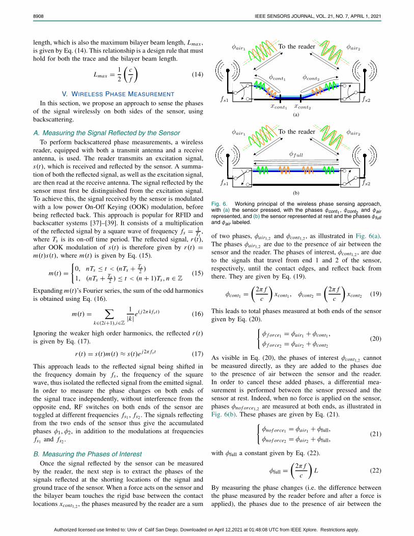
Fig. 6. Working principal of the wireless phase sensing approach,with (a) the sensor pressed, with the phases φcont1 , φcont2 and φairrepresented, and (b) the sensor represented at rest and the phases φfulland φair labeled.
of two phases, φair1,2 and φcont1,2 , as illustrated in Fig. 6(a).The phases φair1,2 are due to the presence of air between thesensor and the reader. The phases of interest, φcont1,2 , are dueto the signals that travel from end 1 and 2 of the sensor,respectively, until the contact edges, and reflect back fromthere. They are given by Eq. (19).
φcont1 =�
2π f
c
�xcont1, φcont2 =
�2π f
c
�xcont2 (19)
This leads to total phases measured at both ends of the sensorgiven by Eq. (20).�
φ f orce1 = φair1 + φcont1,
φ f orce2 = φair2 + φcont2(20)
As visible in Eq. (20), the phases of interest φcont1,2 cannotbe measured directly, as they are added to the phases dueto the presence of air between the sensor and the reader.In order to cancel these added phases, a differential mea-surement is performed between the sensor pressed and thesensor at rest. Indeed, when no force is applied on the sensor,phases φno f orce1,2 are measured at both ends, as illustrated inFig. 6(b). These phases are given by Eq. (21).�
φnof orce1 = φair1 + φfull,
φno f orce2 = φair2 + φfull,(21)
with φfull a constant given by Eq. (22).
φfull =�
2π f
c
�L (22)
By measuring the phase changes (i.e. the difference betweenthe phase measured by the reader before and after a force isapplied), the phases due to the presence of air between the
Authorized licensed use limited to: Univ of Calif San Diego. Downloaded on April 12,2021 at 01:48:08 UTC from IEEE Xplore. Restrictions apply.
GIRERD et al.: TOWARDS WIRELESS FORCE SENSOR FOR MEDICAL APPLICATIONS 8909
TABLE IIMECHANICAL CHARACTERISTICS OF THE BILAYER
BEAM OF THE SENSOR
sensor and the reader are canceled, as shown in Eq. (23).�φno f orce1 − φ f orce1 = φ f ull − φcont1 = φ1,
φno f orce2 − φ f orce2 = φ f ull − φcont2 = φ2,(23)
Hence, the additional phase due to the presence of air can beremoved, and the desired phase information can be obtained,enabling the measurement of the phases due to the displace-ment of the shorting points on the signal trace (please referto [40] for more details on the wireless implementation).
VI. APPLICATION AND FABRICATION
In this section, we apply the design rules and principles pre-sented for the mechanical, electrical and wireless components,and implement a sensor that meets desired requirements.
We start by selecting a frequency for the sensor. As visiblein Eq. (13), the frequency of the sensor should be maximizedin order to accumulate the maximum phase change on bothends of the sensor, and thus increase the resolution. Our focushere is on medical applications, where signal losses increase asa wave goes trough human tissue for frequencies higher than1 GHz [41], [42]. Hence, we select a frequency ( f ) equal to915 MHz in this work. The choice of frequency also allowsus to compute the maximum signal trace and bilayer beamlengths to avoid phase redundancy measurements, as given byEq. (14). For a frequency of f = 915 MHz and a celerityof wave in the electrical trace, c, approximated by the speedof light in the void (299 × 106 m/s), we obtain a maximumlength of Lmax = 164 mm, that must hold for the sensor.
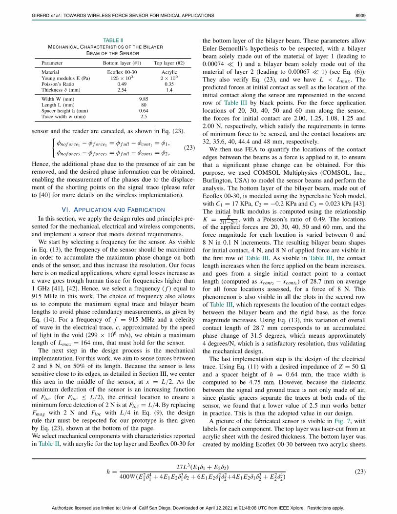
The next step in the design process is the mechanicalimplementation. For this work, we aim to sense forces between2 and 8 N, on 50% of its length. Because the sensor is lesssensitive close to its edges, as detailed in Section III, we centerthis area in the middle of the sensor, at x = L/2. As themaximum deflection of the sensor is an increasing functionof Floc (for Floc ≤ L/2), the critical location to ensure aminimum force detection of 2 N is at Floc = L/4. By replacingFmag with 2 N and Floc with L/4 in Eq. (9), the designrule that must be respected for our prototype is then givenby Eq. (23), shown at the bottom of the page.We select mechanical components with characteristics reportedin Table II, with acrylic for the top layer and Ecoflex 00-30 for
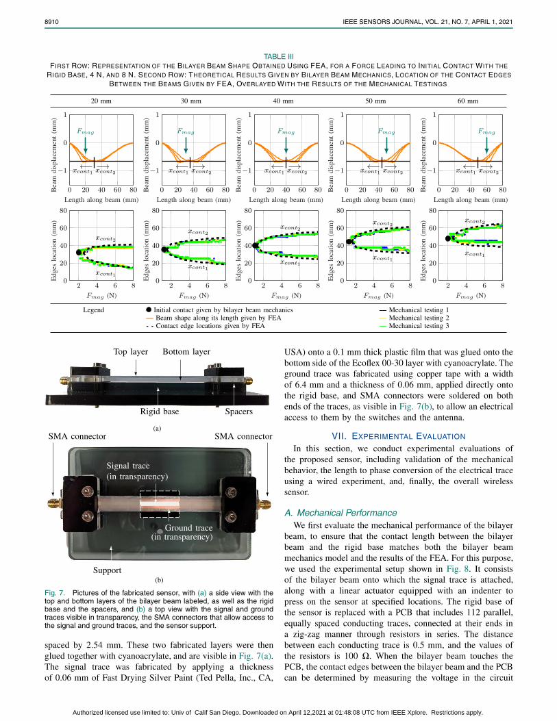
the bottom layer of the bilayer beam. These parameters allowEuler-Bernoulli’s hypothesis to be respected, with a bilayerbeam solely made out of the material of layer 1 (leading to0.00074 � 1) and a bilayer beam solely mode out of thematerial of layer 2 (leading to 0.00067 � 1) (see Eq. (6)).They also verify Eq. (23), and we have L < Lmax . Thepredicted forces at initial contact as well as the location of theinitial contact along the sensor are represented in the secondrow of Table III by black points. For the force applicationlocations of 20, 30, 40, 50 and 60 mm along the sensor,the forces for initial contact are 2.00, 1.25, 1.08, 1.25 and2.00 N, respectively, which satisfy the requirements in termsof minimum force to be sensed, and the contact locations are32, 35.6, 40, 44.4 and 48 mm, respectively.
We then use FEA to quantify the locations of the contactedges between the beams as a force is applied to it, to ensurethat a significant phase change can be obtained. For thispurpose, we used COMSOL Multiphysics (COMSOL, Inc.,Burlington, USA) to model the sensor beams and perform theanalysis. The bottom layer of the bilayer beam, made out ofEcoflex 00-30, is modeled using the hyperelastic Yeoh model,with C1 = 17 KPa, C2 = −0.2 KPa and C3 = 0.023 kPa [43].The initial bulk modulus is computed using the relationshipK = E
3(1−2ν) , with a Poisson’s ratio of 0.49. The locationsof the applied forces are 20, 30, 40, 50 and 60 mm, and theforce magnitude for each location is varied between 0 and8 N in 0.1 N increments. The resulting bilayer beam shapesfor initial contact, 4 N, and 8 N of applied force are visible inthe first row of Table III. As visible in Table III, the contactlength increases when the force applied on the beam increases,and goes from a single initial contact point to a contactlength (computed as xcont2 − xcont1) of 28.7 mm on averagefor all force locations assessed, for a force of 8 N. Thisphenomenon is also visible in all the plots in the second rowof Table III, which represents the location of the contact edgesbetween the bilayer beam and the rigid base, as the forcemagnitude increases. Using Eq. (13), this variation of overallcontact length of 28.7 mm corresponds to an accumulatedphase change of 31.5 degrees, which means approximately4 degrees/N, which is a satisfactory resolution, thus validatingthe mechanical design.
The last implementation step is the design of the electricaltrace. Using Eq. (11) with a desired impedance of Z = 50 �and a spacer height of h = 0.64 mm, the trace width iscomputed to be 4.75 mm. However, because the dielectricbetween the signal and ground trace is not only made of air,since plastic spacers separate the traces at both ends of thesensor, we found that a lower value of 2.5 mm works betterin practice. This is thus the adopted value in our design.
A picture of the fabricated sensor is visible in Fig. 7, withlabels for each component. The top layer was laser-cut from anacrylic sheet with the desired thickness. The bottom layer wascreated by molding Ecoflex 00-30 between two acrylic sheets
h = 27L3(E1δ1 + E2δ2)
400W (E21δ4
1 + 4E1 E2δ31δ2 + 6E1 E2δ
21δ2
2+4E1 E2δ1δ32 + E2
2δ42)
(23)
Authorized licensed use limited to: Univ of Calif San Diego. Downloaded on April 12,2021 at 01:48:08 UTC from IEEE Xplore. Restrictions apply.
8910 IEEE SENSORS JOURNAL, VOL. 21, NO. 7, APRIL 1, 2021
TABLE IIIFIRST ROW: REPRESENTATION OF THE BILAYER BEAM SHAPE OBTAINED USING FEA, FOR A FORCE LEADING TO INITIAL CONTACT WITH THE
RIGID BASE, 4 N, AND 8 N. SECOND ROW: THEORETICAL RESULTS GIVEN BY BILAYER BEAM MECHANICS, LOCATION OF THE CONTACT EDGES
BETWEEN THE BEAMS GIVEN BY FEA, OVERLAYED WITH THE RESULTS OF THE MECHANICAL TESTINGS
Fig. 7. Pictures of the fabricated sensor, with (a) a side view with thetop and bottom layers of the bilayer beam labeled, as well as the rigidbase and the spacers, and (b) a top view with the signal and groundtraces visible in transparency, the SMA connectors that allow access tothe signal and ground traces, and the sensor support.
spaced by 2.54 mm. These two fabricated layers were thenglued together with cyanoacrylate, and are visible in Fig. 7(a).The signal trace was fabricated by applying a thicknessof 0.06 mm of Fast Drying Silver Paint (Ted Pella, Inc., CA,
USA) onto a 0.1 mm thick plastic film that was glued onto thebottom side of the Ecoflex 00-30 layer with cyanoacrylate. Theground trace was fabricated using copper tape with a widthof 6.4 mm and a thickness of 0.06 mm, applied directly ontothe rigid base, and SMA connectors were soldered on bothends of the traces, as visible in Fig. 7(b), to allow an electricalaccess to them by the switches and the antenna.
VII. EXPERIMENTAL EVALUATION
In this section, we conduct experimental evaluations ofthe proposed sensor, including validation of the mechanicalbehavior, the length to phase conversion of the electrical traceusing a wired experiment, and, finally, the overall wirelesssensor.
A. Mechanical PerformanceWe first evaluate the mechanical performance of the bilayer
beam, to ensure that the contact length between the bilayerbeam and the rigid base matches both the bilayer beammechanics model and the results of the FEA. For this purpose,we used the experimental setup shown in Fig. 8. It consistsof the bilayer beam onto which the signal trace is attached,along with a linear actuator equipped with an indenter topress on the sensor at specified locations. The rigid base ofthe sensor is replaced with a PCB that includes 112 parallel,equally spaced conducting traces, connected at their ends ina zig-zag manner through resistors in series. The distancebetween each conducting trace is 0.5 mm, and the values ofthe resistors is 100 �. When the bilayer beam touches thePCB, the contact edges between the bilayer beam and the PCBcan be determined by measuring the voltage in the circuit
Authorized licensed use limited to: Univ of Calif San Diego. Downloaded on April 12,2021 at 01:48:08 UTC from IEEE Xplore. Restrictions apply.
GIRERD et al.: TOWARDS WIRELESS FORCE SENSOR FOR MEDICAL APPLICATIONS 8911
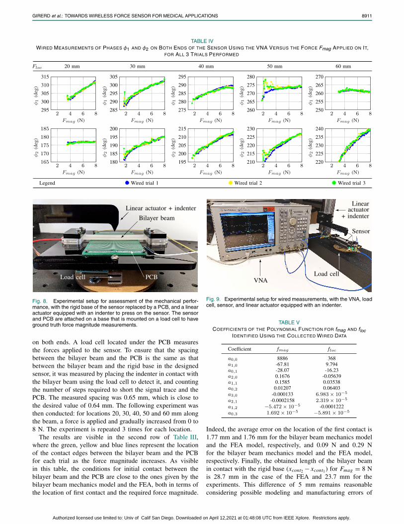
TABLE IVWIRED MEASUREMENTS OF PHASES φ1 AND φ2 ON BOTH ENDS OF THE SENSOR USING THE VNA VERSUS THE FORCE Fmag APPLIED ON IT,
FOR ALL 3 TRIALS PERFORMED
Fig. 8. Experimental setup for assessment of the mechanical perfor-mance, with the rigid base of the sensor replaced by a PCB, and a linearactuator equipped with an indenter to press on the sensor. The sensorand PCB are attached on a base that is mounted on a load cell to haveground truth force magnitude measurements.
on both ends. A load cell located under the PCB measuresthe forces applied to the sensor. To ensure that the spacingbetween the bilayer beam and the PCB is the same as thatbetween the bilayer beam and the rigid base in the designedsensor, it was measured by placing the indenter in contact withthe bilayer beam using the load cell to detect it, and countingthe number of steps required to short the signal trace and thePCB. The measured spacing was 0.65 mm, which is close tothe desired value of 0.64 mm. The following experiment wasthen conducted: for locations 20, 30, 40, 50 and 60 mm alongthe beam, a force is applied and gradually increased from 0 to8 N. The experiment is repeated 3 times for each location.
The results are visible in the second row of Table III,where the green, yellow and blue lines represent the locationof the contact edges between the bilayer beam and the PCBfor each trial as the force magnitude increases. As visiblein this table, the conditions for initial contact between thebilayer beam and the PCB are close to the ones given by thebilayer beam mechanics model and the FEA, both in terms ofthe location of first contact and the required force magnitude.
Fig. 9. Experimental setup for wired measurements, with the VNA, loadcell, sensor, and linear actuator equipped with an indenter.
TABLE VCOEFFICIENTS OF THE POLYNOMIAL FUNCTION FOR fmag AND floc
IDENTIFIED USING THE COLLECTED WIRED DATA
Indeed, the average error on the location of the first contact is1.77 mm and 1.76 mm for the bilayer beam mechanics modeland the FEA model, respectively, and 0.09 N and 0.29 Nfor the bilayer beam mechanics model and the FEA model,respectively. Finally, the obtained length of the bilayer beamin contact with the rigid base (xcont2 − xcont1) for Fmag = 8 Nis 28.7 mm in the case of the FEA and 23.7 mm for theexperiments. This difference of 5 mm remains reasonableconsidering possible modeling and manufacturing errors of
Authorized licensed use limited to: Univ of Calif San Diego. Downloaded on April 12,2021 at 01:48:08 UTC from IEEE Xplore. Restrictions apply.
8912 IEEE SENSORS JOURNAL, VOL. 21, NO. 7, APRIL 1, 2021
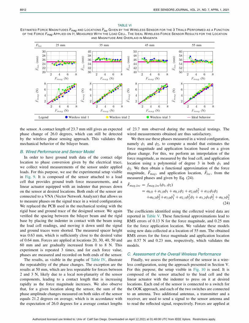
TABLE VIESTIMATED FORCE MAGNITUDES F̃mag AND LOCATIONS F̃loc GIVEN BY THE WIRELESS SENSOR FOR THE 3 TRIALS PERFORMED AS A FUNCTION
OF THE FORCE Fmag APPLIED ON IT, MEASURED WITH THE LOAD CELL. THE IDEAL WIRELESS FORCE SENSOR RESULTS FOR THE LOCATION
AND MAGNITUDE ARE OVERLAID IN MAGENTA
the sensor. A contact length of 23.7 mm still gives an expectedphase change of 26.0 degrees, which can still be detectedby the wireless phase sensing approach. This validates themechanical behavior of the bilayer beam.
B. Wired Performance and Sensor ModelIn order to have ground truth data of the contact edge
location to phase conversion given by the electrical trace,we collect wired measurements of the sensor under appliedloads. For this purpose, we use the experimental setup visiblein Fig. 9. It is composed of the sensor attached to a loadcell that provides ground truth force measurements, and alinear actuator equipped with an indenter that presses downon the sensor at desired locations. Both ends of the sensor areconnected to a VNA (Vector Network Analyzer) that allows usto measure phases on the signal trace in a wired configuration.We replaced the PCB used in the mechanical testing with therigid base and ground trace of the designed sensor. We againverified the spacing between the bilayer beam and the rigidbase by placing the indenter in contact with the beam usingthe load cell readings, and moving it down until the signaland ground traces were shorted. The measured spacer heightwas 0.63 mm, which is sufficiently close to the desired valueof 0.64 mm. Forces are applied at locations 20, 30, 40, 50 and60 mm and are gradually increased from 0 to 8 N. Thisexperiment is repeated 3 times, and for each force value,phases are measured and recorded on both ends of the sensor.
The results, as visible in the graphs of Table IV, illustratethe repeatability of the phase changes. The exception are theresults at 50 mm, which are less repeatable for forces between2 and 3 N, likely due to a local non-planarity of the sensorcomponents, leading to a contact length that is increasingrapidly as the force magnitude increases. We also observethat, for a given location along the sensor, the sum of thephase amplitude changes measured on both sides of the sensorequals 21.2 degrees on average, which is in accordance withthe expectation of 26.0 degrees for a average contact lengths
of 23.7 mm observed during the mechanical testings. Thewired measurements obtained are thus satisfactory.
We then use these phases measured in a wired configuration,namely φ1 and φ2, to compute a model that estimates theforce magnitude and application location based on a givenphase change. For this, we perform an interpolation of theforce magnitude, as measured by the load cell, and applicationlocation using a polynomial of degree 3 in both φ1 andφ2. We then obtain a functional approximation of the forcemagnitude, F̃mag , and application location, F̃loc, from themeasured phases and given by Eq. (24).
F̃mag,loc = fmag,loc(φ1, φ2)
= a0,0 + a1,0φ1 + a0,1φ2 + a2,0φ21 + a11φ1φ2
+a0,2φ22 +a3,0φ
31 + a2,1φ
21φ2 + a1,2φ1φ
22 + a0,3φ
32
(24)
The coefficients identified using the collected wired data arereported in Table V. These functional approximations lead toRMS errors of 0.13 N for the force magnitude, and 0.25 mmfor the force application location. We validate these modelsusing new data collected at a location of 55 mm. The obtainedRMS errors for the force magnitude and application locationare 0.57 N and 0.23 mm, respectively, which validates themodels.
C. Assessment of the Overall Wireless PerformanceFinally, we assess the performance of the sensor in a wire-
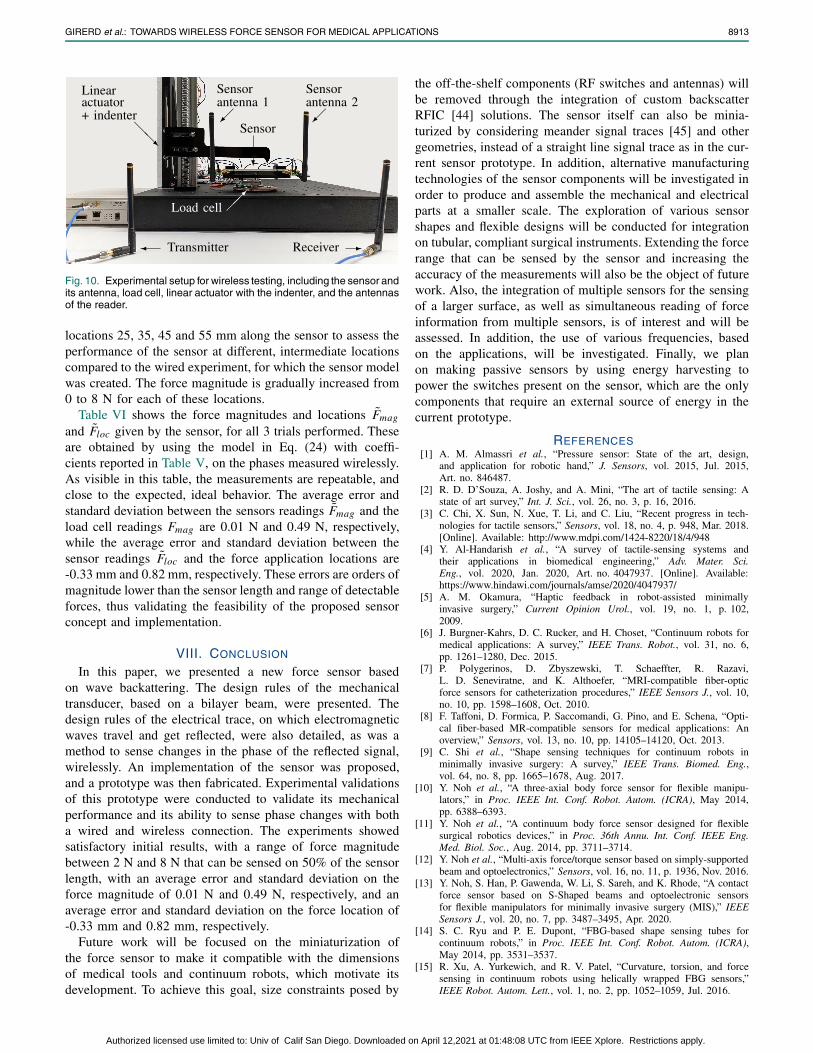
less configuration, using the approach presented in Section V.For this purpose, the setup visible in Fig. 10 is used. It iscomposed of the sensor attached to the load cell and thelinear actuator with the indenter to press on it at desiredlocations. Each end of the sensor is connected to a switch forthe OOK approach, and each of the two switches are connectedto an antenna. Two additional antennas, a transmitter and areceiver, are used to send a signal to the sensor antenna andto read the reflected signal, respectively. Forces are applied at
Authorized licensed use limited to: Univ of Calif San Diego. Downloaded on April 12,2021 at 01:48:08 UTC from IEEE Xplore. Restrictions apply.
GIRERD et al.: TOWARDS WIRELESS FORCE SENSOR FOR MEDICAL APPLICATIONS 8913
Fig. 10. Experimental setup for wireless testing, including the sensor andits antenna, load cell, linear actuator with the indenter, and the antennasof the reader.
locations 25, 35, 45 and 55 mm along the sensor to assess theperformance of the sensor at different, intermediate locationscompared to the wired experiment, for which the sensor modelwas created. The force magnitude is gradually increased from0 to 8 N for each of these locations.
Table VI shows the force magnitudes and locations F̃mag
and F̃loc given by the sensor, for all 3 trials performed. Theseare obtained by using the model in Eq. (24) with coeffi-cients reported in Table V, on the phases measured wirelessly.As visible in this table, the measurements are repeatable, andclose to the expected, ideal behavior. The average error andstandard deviation between the sensors readings F̃mag and theload cell readings Fmag are 0.01 N and 0.49 N, respectively,while the average error and standard deviation between thesensor readings F̃loc and the force application locations are-0.33 mm and 0.82 mm, respectively. These errors are orders ofmagnitude lower than the sensor length and range of detectableforces, thus validating the feasibility of the proposed sensorconcept and implementation.
VIII. CONCLUSION
In this paper, we presented a new force sensor basedon wave backattering. The design rules of the mechanicaltransducer, based on a bilayer beam, were presented. Thedesign rules of the electrical trace, on which electromagneticwaves travel and get reflected, were also detailed, as was amethod to sense changes in the phase of the reflected signal,wirelessly. An implementation of the sensor was proposed,and a prototype was then fabricated. Experimental validationsof this prototype were conducted to validate its mechanicalperformance and its ability to sense phase changes with botha wired and wireless connection. The experiments showedsatisfactory initial results, with a range of force magnitudebetween 2 N and 8 N that can be sensed on 50% of the sensorlength, with an average error and standard deviation on theforce magnitude of 0.01 N and 0.49 N, respectively, and anaverage error and standard deviation on the force location of-0.33 mm and 0.82 mm, respectively.
Future work will be focused on the miniaturization ofthe force sensor to make it compatible with the dimensionsof medical tools and continuum robots, which motivate itsdevelopment. To achieve this goal, size constraints posed by
the off-the-shelf components (RF switches and antennas) willbe removed through the integration of custom backscatterRFIC [44] solutions. The sensor itself can also be minia-turized by considering meander signal traces [45] and othergeometries, instead of a straight line signal trace as in the cur-rent sensor prototype. In addition, alternative manufacturingtechnologies of the sensor components will be investigated inorder to produce and assemble the mechanical and electricalparts at a smaller scale. The exploration of various sensorshapes and flexible designs will be conducted for integrationon tubular, compliant surgical instruments. Extending the forcerange that can be sensed by the sensor and increasing theaccuracy of the measurements will also be the object of futurework. Also, the integration of multiple sensors for the sensingof a larger surface, as well as simultaneous reading of forceinformation from multiple sensors, is of interest and will beassessed. In addition, the use of various frequencies, basedon the applications, will be investigated. Finally, we planon making passive sensors by using energy harvesting topower the switches present on the sensor, which are the onlycomponents that require an external source of energy in thecurrent prototype.
REFERENCES[1] A. M. Almassri et al., “Pressure sensor: State of the art, design,
and application for robotic hand,” J. Sensors, vol. 2015, Jul. 2015,Art. no. 846487.
[2] R. D. D’Souza, A. Joshy, and A. Mini, “The art of tactile sensing: Astate of art survey,” Int. J. Sci., vol. 26, no. 3, p. 16, 2016.
[3] C. Chi, X. Sun, N. Xue, T. Li, and C. Liu, “Recent progress in tech-nologies for tactile sensors,” Sensors, vol. 18, no. 4, p. 948, Mar. 2018.[Online]. Available: http://www.mdpi.com/1424-8220/18/4/948
[4] Y. Al-Handarish et al., “A survey of tactile-sensing systems andtheir applications in biomedical engineering,” Adv. Mater. Sci.Eng., vol. 2020, Jan. 2020, Art. no. 4047937. [Online]. Available:https://www.hindawi.com/journals/amse/2020/4047937/
[5] A. M. Okamura, “Haptic feedback in robot-assisted minimallyinvasive surgery,” Current Opinion Urol., vol. 19, no. 1, p. 102,2009.
[6] J. Burgner-Kahrs, D. C. Rucker, and H. Choset, “Continuum robots formedical applications: A survey,” IEEE Trans. Robot., vol. 31, no. 6,pp. 1261–1280, Dec. 2015.
[7] P. Polygerinos, D. Zbyszewski, T. Schaeffter, R. Razavi,L. D. Seneviratne, and K. Althoefer, “MRI-compatible fiber-opticforce sensors for catheterization procedures,” IEEE Sensors J., vol. 10,no. 10, pp. 1598–1608, Oct. 2010.
[8] F. Taffoni, D. Formica, P. Saccomandi, G. Pino, and E. Schena, “Opti-cal fiber-based MR-compatible sensors for medical applications: Anoverview,” Sensors, vol. 13, no. 10, pp. 14105–14120, Oct. 2013.
[9] C. Shi et al., “Shape sensing techniques for continuum robots inminimally invasive surgery: A survey,” IEEE Trans. Biomed. Eng.,vol. 64, no. 8, pp. 1665–1678, Aug. 2017.
[10] Y. Noh et al., “A three-axial body force sensor for flexible manipu-lators,” in Proc. IEEE Int. Conf. Robot. Autom. (ICRA), May 2014,pp. 6388–6393.
[11] Y. Noh et al., “A continuum body force sensor designed for flexiblesurgical robotics devices,” in Proc. 36th Annu. Int. Conf. IEEE Eng.Med. Biol. Soc., Aug. 2014, pp. 3711–3714.
[12] Y. Noh et al., “Multi-axis force/torque sensor based on simply-supportedbeam and optoelectronics,” Sensors, vol. 16, no. 11, p. 1936, Nov. 2016.
[13] Y. Noh, S. Han, P. Gawenda, W. Li, S. Sareh, and K. Rhode, “A contactforce sensor based on S-Shaped beams and optoelectronic sensorsfor flexible manipulators for minimally invasive surgery (MIS),” IEEESensors J., vol. 20, no. 7, pp. 3487–3495, Apr. 2020.
[14] S. C. Ryu and P. E. Dupont, “FBG-based shape sensing tubes forcontinuum robots,” in Proc. IEEE Int. Conf. Robot. Autom. (ICRA),May 2014, pp. 3531–3537.
[15] R. Xu, A. Yurkewich, and R. V. Patel, “Curvature, torsion, and forcesensing in continuum robots using helically wrapped FBG sensors,”IEEE Robot. Autom. Lett., vol. 1, no. 2, pp. 1052–1059, Jul. 2016.
Authorized licensed use limited to: Univ of Calif San Diego. Downloaded on April 12,2021 at 01:48:08 UTC from IEEE Xplore. Restrictions apply.
8914 IEEE SENSORS JOURNAL, VOL. 21, NO. 7, APRIL 1, 2021
[16] T. Chen et al., “Novel, flexible and ultra-thin pressure feed-back sensor for miniaturized intra-ventricular neurosurgery robotictools,” IEEE Trans. Ind. Electron., early access, Apr. 9, 2020, doi:10.1109/TIE.2020.2984427.
[17] M. Sim et al., “Psychological tactile sensor structure based on piezo-electric sensor arrays,” in Proc. IEEE World Haptics Conf. (WHC),Jun. 2017, pp. 340–345.
[18] E. Lou, V. J. Raso, B. Martin, M. Epper, and D. L. Hill, “A wirelessload measurement tool for spine surgery,” in Proc. IEEE Instrum. Meas.Technol. Conf., vol. 3, May 2005, pp. 1813–1817.
[19] C. Li et al., “Review of research status and development trends ofwireless passive LC resonant sensors for harsh environments,” Sensors,vol. 15, no. 6, pp. 13097–13109, Jun. 2015.
[20] E. L. Tan, B. D. Pereles, R. Shao, J. Ong, and K. G. Ong, “A wireless,passive strain sensor based on the harmonic response of magneti-cally soft materials,” Smart Mater. Struct., vol. 17, no. 2, Apr. 2008,Art. no. 025015.
[21] Q.-A. Huang, L. Dong, and L.-F. Wang, “LC passive wireless sensorstoward a wireless sensing platform: Status, prospects, and challenges,”J. Microelectromech. Syst., vol. 25, no. 5, pp. 822–841, Oct. 2016.
[22] S. Pradhan, E. Chai, K. Sundaresan, L. Qiu, M. A. Khojastepour,and S. Rangarajan, “Rio: A pervasive RFID-based touch gesture inter-face,” in Proc. 23rd Annu. Int. Conf. Mobile Comput. Netw., 2017,pp. 261–274.
[23] H. Li, C. Ye, and A. P. Sample, “IDSense: A human object interactiondetection system based on passive UHF RFID,” in Proc. 33rd Annu.ACM Conf. Hum. Factors Comput. Syst., 2015, pp. 2555–2564.
[24] C. Gao, Y. Li, and X. Zhang, “LiveTag: Sensing human-object interac-tion through passive chipless WiFi tags,” in Proc. 15th USENIX Symp.Netw. Syst. Design Implement. (NSDI), 2018, pp. 533–546.
[25] N. Marquardt, A. S. Taylor, N. Villar, and S. Greenberg, “RethinkingRFID: Awareness and control for interaction with RFID systems,” inProc. SIGCHI Conf. Hum. Factors Comput. Syst., 2010, pp. 2307–2316.
[26] A. P. Sample, D. J. Yeager, and J. R. Smith, “A capacitive touch interfacefor passive RFID tags,” in Proc. IEEE Int. Conf. RFID, Apr. 2009,pp. 103–109.
[27] T. M. Simon, B. H. Thomas, R. T. Smith, and M. Smith, “Addinginput controls and sensors to RFID tags to support dynamic tangibleuser interfaces,” in Proc. 8th Int. Conf. Tangible, Embedded EmbodiedInteract. (TEI), 2013, pp. 165–172.
[28] A. Schmidt, H.-W. Gellersen, and C. Merz, “Enabling implicit humancomputer interaction: A wearable RFID-tag reader,” in Dig. Papers. 4thInt. Symp. Wearable Comput., Oct. 2000, pp. 193–194.
[29] H. Li et al., “Paperid: A technique for drawing functional battery-freewireless interfaces on paper,” in Proc. CHI Conf. Hum. Factors Comput.Syst., 2016, pp. 5885–5896.
[30] H. Li et al., “A miniature layered SAW contact stress sensor foroperation in cramped metallic slits,” Instrum. Exp. Techn., vol. 61, no. 4,pp. 610–617, Jul. 2018.
[31] X. Yi, T. Wu, Y. Wang, R. T. Leon, M. M. Tentzeris, and G. Lantz,“Passive wireless smart-skin sensor using RFID-based folded patchantennas,” Int. J. Smart Nano Mater., vol. 2, no. 1, pp. 22–38, Feb. 2011.
[32] T. T. Thai, H. Aubert, P. Pons, M. M. Tentzeris, and R. Plana, “Designof a highly sensitive wireless passive RF strain transducer,” in IEEEMTT-S Int. Microw. Symp. Dig., Jun. 2011, pp. 1–4.
[33] J. R. Humphries and D. C. Malocha, “Passive, wireless SAW OFC strainsensor,” in Proc. IEEE Int. Freq. Control Symp., May 2012, pp. 1–6.
[34] J. Bareisis, “Stiffness and strength of multilayer beams,” J. CompositeMater., vol. 40, no. 6, pp. 515–531, Mar. 2006.
[35] R. Hartley. (Dec. 1, 2020). RF/Microwave PC Board Design and Layout.[Online]. Available: https://www.jlab.org/accel/eecad/pdf/050rfdesign.pdf
[36] R. C. Johnson, “Design of linear double tapers in rectangularwaveguides,” IEEE Trans. Microw. Theory Techn., vol. 7, no. 3,pp. 374–378, Jul. 1959.
[37] P. Zhang, C. Josephson, D. Bharadia, and S. Katti, “FreeRider:Backscatter communication using commodity radios,” in Proc. 13th Int.Conf. Emerg. Netw. Exp. Technol., New York, NY, USA, Nov. 2017,pp. 389–401, doi: 10.1145/3143361.3143374.
[38] P. Zhang, D. Bharadia, K. Joshi, and S. Katti, “HitchHike: Practicalbackscatter using commodity WiFi,” in Proc. 14th ACM Conf. EmbeddedNetw. Sensor Syst. (CD-ROM), New York, NY, USA, Nov. 2016, p. 259,doi: 10.1145/2994551.2994565.
[39] Z. Luo, Q. Zhang, Y. Ma, M. Singh, and F. Adib, “3D backscatterlocalization for fine-grained robotics,” in Proc. 16th USENIX Symp.Netw. Syst. Design Implement. (NSDI), 2019, pp. 765–782.
[40] A. Gupta et al., “Wi-chlorian: Wireless sensing and localization ofcontact forces on a space continuum,” 2020, arXiv:2012.15412. [Online].Available: http://arxiv.org/abs/2012.15412
[41] S. K. S. Gupta, S. Lalwani, Y. Prakash, E. Elsharawy, andL. Schwiebert, “Towards a propagation model for wireless biomed-ical applications,” in Proc. IEEE Int. Conf. Commun. (ICC), vol. 3,May 2003, pp. 1993–1997.
[42] D. Vasisht, G. Zhang, O. Abari, H.-M. Lu, J. Flanz, and D. Katabi, “In-body backscatter communication and localization,” in Proc. Conf. ACMSpecial Interest Group Data Commun., Aug. 2018, pp. 132–146.
[43] D. Steck, J. Qu, S. B. Kordmahale, D. Tscharnuter, A. Muliana, andJ. Kameoka, “Mechanical responses of ecoflex silicone rubber: Com-pressible and incompressible behaviors,” J. Appl. Polym. Sci., vol. 136,no. 5, p. 47025, Feb. 2019.
[44] P. P. Wang, C. Zhang, H. Yang, D. Bharadia, and P. P. Mercier, “20.1 A28μW IoT tag that can communicate with commodity WiFi transceiversvia a single-side-band QPSK backscatter communication technique,”in IEEE Int. Solid-State Circuits Conf. (ISSCC) Dig. Tech. Papers,Feb. 2020, pp. 312–314.
[45] S. Bokhari, “Precision delay matching by trace length control in printedcircuit boards,” in Proc. Can. Conf. Electr. Comput. Eng., May 2006,pp. 799–802.
Cédric Girerd received the bachelor’s degree inmechatronics from SIGMA Clermont, the M.Sc.degree in robotics from the University of BlaisePascal, Clermont-Ferrand, France, in 2014, andthe Ph.D. degree in robotics from the Universityof Strasbourg, France, in 2018. He is currentlyworking as a Postdoctoral Researcher with theUniversity of California, San Diego. His researchfocuses on the design and control of continuumrobots.
Qiming Zhang is currently pursuing the mas-ter’s degree in bioengineering with the Universityof California, San Diego. His research interestsinclude the development of surgical robotics andbio-inspired instruments.
Agrim Gupta received the B.Tech. andM.Tech. (Hons.) degrees from the IndianInstitute of Technology Bombay in 2019, withUndergraduate Research Award for his thesiswork on MIMO-OFDM precoding. He is currentlypursuing the Ph.D. degree with the Universityof California, San Diego (UCSD) with theWCSNG research group headed by Prof. DineshBharadia. His research focuses on low-powerwireless sensing, wireless localization, andMIMO systems.
Manideep Dunna received the B.Tech. andM.Tech. (Hons.) degrees from the Indian Insti-tute of Technology Madras in 2017 and 2018,respectively. He is currently pursuing the Ph.D.degree with the University of California, SanDiego (UCSD), with the WCSNG research group.His research focuses on using backscatter tech-niques for low power wireless relays. He was arecipient of the Charles Lee Powell fellowship atUCSD.
Authorized licensed use limited to: Univ of Calif San Diego. Downloaded on April 12,2021 at 01:48:08 UTC from IEEE Xplore. Restrictions apply.
GIRERD et al.: TOWARDS WIRELESS FORCE SENSOR FOR MEDICAL APPLICATIONS 8915
Dinesh Bharadia (Member, IEEE) received thebachelor’s degree in electrical engineering fromthe Indian Institute of Technology, Kanpur, in2010, and the Ph.D. degree from the Electri-cal Engineering Department, Stanford University.He is an Assistant Professor with UC San Diego,where he leads the wireless communicationsensing and networking group (WCSNG). Hisresearch interests include advancing the theoryand design of modern wireless communicationand sensing systems, and low-power networks.
In recognition of his research, he was named a Marconi Young Scholarfor outstanding wireless research and awarded the Michael DukkakisLeadership award. He was also named as one of the top 35 Innovatorsunder 35 in the world by MIT Technology Review in 2016 and worldwideForbes 30 under and 30 for Science category in 2018. His Ph.D. thesisinvalidated a long-held assumption in wireless communication by buildingfull-duplex radios. From 2013 to 2015, he was a Principal Scientist forKumu Networks, where he worked to commercialize his research onfull-duplex radios, building a product which underwent successful fieldtrials at Tier 1 network providers worldwide like Deutsche Telekom andSK Telecom. He was a recipient of the Stanford Graduate Fellowship,as well as a gold medal at IIT Kanpur for graduating at the top of hisclass.
Tania. K. Morimoto (Member, IEEE) receivedthe B.S. degree from the Massachusetts Insti-tute of Technology, Cambridge, MA, in 2012,and the M.S. and Ph.D. degrees from Stan-ford University, Stanford, CA, in 2015 and 2017,respectively, all in mechanical engineering. Sheis currently an Assistant Professor of Mechanicaland Aerospace Engineering and an AssistantProfessor of Surgery with the University of Cali-fornia, San Diego. Her research interests includerobotics, haptics, and engineering education.
Authorized licensed use limited to: Univ of Calif San Diego. Downloaded on April 12,2021 at 01:48:08 UTC from IEEE Xplore. Restrictions apply.