Embed Size (px)
Citation preview

Towards a Model-Based Toolchain for High Confidence Design
Peter Volgyesi
Gabor Karsai
Janos Sztipanovits
Sandeep Neema
Harmon Nine
Joe Porter
Ryan Thibodeaux
Vanderbilt University/ISIS
2
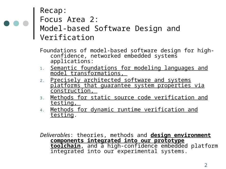
Recap:Focus Area 2:Model-based Software Design and Verification
Foundations of model-based software design for high-confidence, networked embedded systems applications:
1. Semantic foundations for modeling languages and model transformations,
2. Precisely architected software and systems platforms that guarantee system properties via construction,
3. Methods for static source code verification and testing, 4. Methods for dynamic runtime verification and testing.
Deliverables: theories, methods and design environment components integrated into our prototype toolchain, and a high-confidence embedded platform integrated into our experimental systems.
3
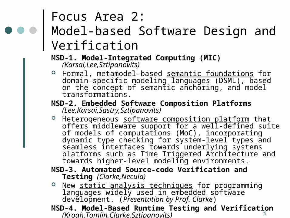
Focus Area 2:Model-based Software Design and Verification MSD-1. Model-Integrated Computing (MIC) (Karsai,Lee,Sztipanovits) Formal, metamodel-based semantic foundations for domain-specific
modeling languages (DSML), based on the concept of semantic anchoring, and model transformations.
MSD-2. Embedded Software Composition Platforms (Lee,Karsai,Sastry,Sztipanovits)
Heterogeneous software composition platform that offers middleware support for a well-defined suite of models of computations (MoC), incorporating dynamic type checking for system-level types and seamless interfaces towards underlying systems platforms such as Time Triggered Architecture and towards higher-level modeling environments.
MSD-3. Automated Source-code Verification and Testing (Clarke,Necula)
New static analysis techniques for programming languages widely used in embedded software development. (Presentation by Prof. Clarke)
MSD-4. Model-Based Runtime Testing and Verification (Krogh,Tomlin,Clarke,Sztipanovits)
Algorithms for the runtime, passive conformance testing of system behavior to a set of approximate models.
4
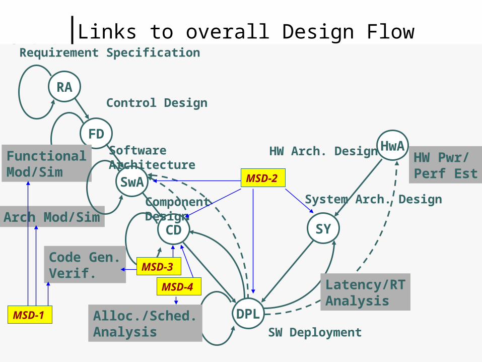
Links to overall Design Flow
RA
FD
CD
HwA
SY
DPL
FunctionalMod/Sim
Arch Mod/Sim
Alloc./Sched.Analysis
HW Pwr/Perf Est
Latency/RTAnalysis
SwA
Requirement Specification
Control Design
Component Design
Software Architecture
HW Arch. Design
System Arch. Design
Code Gen.Verif.
SW Deployment
MSD-1
MSD-2
MSD-3
MSD-4
5
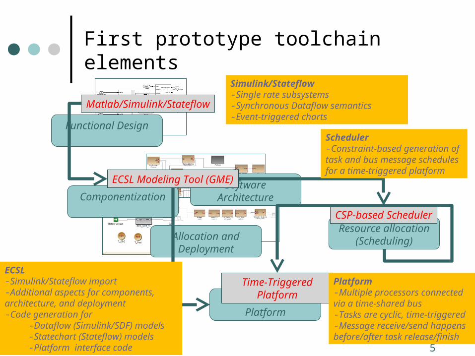
First prototype toolchain elements
Functional Design
Resource allocation(Scheduling)
Execution Platform
Software ArchitectureComponentization
Allocation and Deployment
Matlab/Simulink/Stateflow
ECSL Modeling Tool (GME)
CSP-based Scheduler
Time-Triggered Platform
Simulink/Stateflow -Single rate subsystems-Synchronous Dataflow semantics-Event-triggered charts
ECSL-Simulink/Stateflow import-Additional aspects for components, architecture, and deployment -Code generation for
-Dataflow (Simulink/SDF) models-Statechart (Stateflow) models-Platform interface code
Scheduler-Constraint-based generation of task and bus message schedules for a time-triggered platform
Platform-Multiple processors connected via a time-shared bus-Tasks are cyclic, time-triggered-Message receive/send happens before/after task release/finish
6
Design rationale for prototype toolchain (1)
The connection towards Simulink/Stateflow Simulink/Stateflow is the industry standard SDF and (restricted) Statechart semantics is well-defined and
widely used Could be substituted in later stages of the project
The ECSL language Software components and architectures and deployment had to be
captured in models and integrated with the functional models. Not all features of Simulink/Stateflow are supported – only a ‘safe’
subset. Dataflow (Simulink/SDF) model: scheduling based on the time-
triggered paradigm (t_k is determined by an off-line scheduler) receive(t_k) execute() send(t_k+1)
Extensible towards other models of computation
7
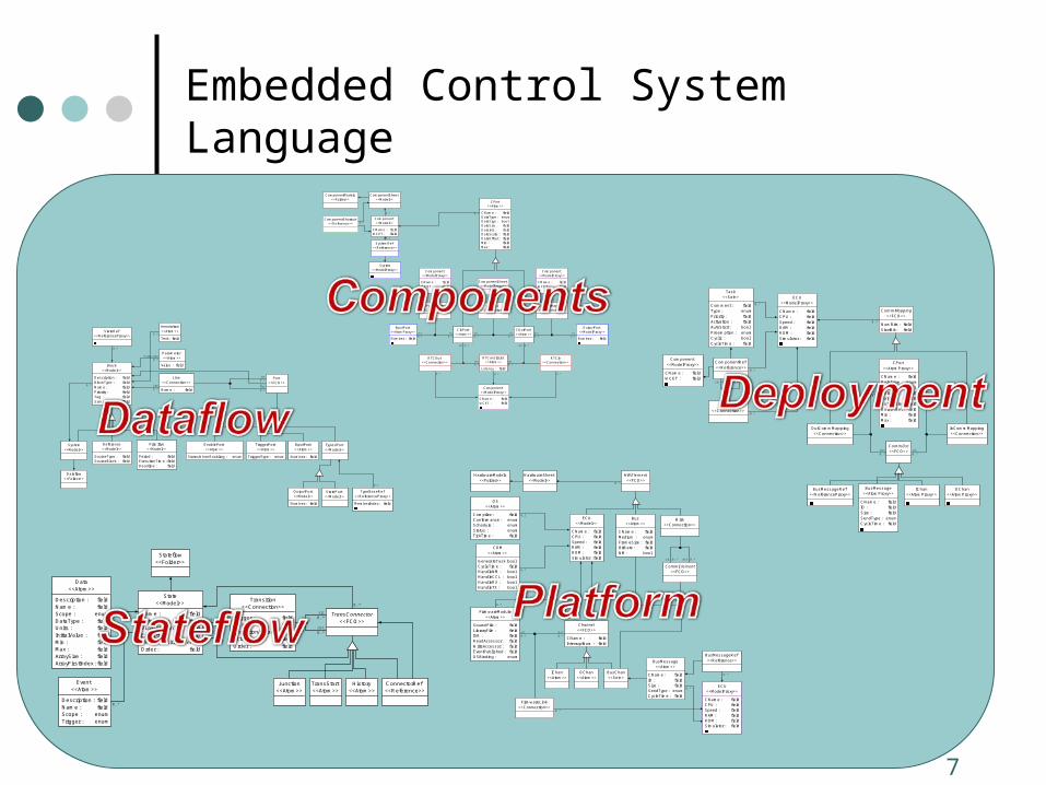
Embedded Control System Language
Parameter<<Atom>>
Value : field
Reference<<Model>>
SourceType : fieldSourceBlock : field
Annotation<<Atom>>
Text : field
Primitive<<Model>>
Period : fieldExecutionTime : fieldDeadline : field
Line<<Connection>>
Name : field
InputPort<<Atom>>
Number : field
Block<<Model>>
Description : fieldBlockType : fieldName : fieldPriority : fieldTag : fieldSampleTime : field
TriggerPort<<Atom>>
TriggerType : enum
Dataflow<<Folder>>
EnablePort<<Atom>>
StatesWhenEnabling : enum
System<<Model>>
OutputPort<<Model>>
Number : field
Port<<FCO>>
TypedPort<<Model>>
StatePort<<Model>>
StateRef<<ReferenceProxy>>
TypeBaseRef<<ReferenceProxy>>
MemberIndex : field
0..1
0..*dst0..*
src0..*
0..*
0..*
Line0..*
Parameter0..*
0..*
TransConnector<<FCO>>
Data<<Atom>>
Description : fieldName : fieldScope : enumDataType : fieldUnits : fieldInitialValue : fieldMin : fieldMax : fieldArraySize : fieldArrayFirstIndex : field
Stateflow<<Folder>>
Junction<<Atom>>
TransStart<<Atom>>
History<<Atom>>
Event<<Atom>>
Description : fieldName : fieldScope : enumTrigger : enum
Transition<<Connection>>
Trigger : fieldGuard : fieldConditionAction : fieldAction : fieldOrder : field
State<<Model>>
Name : fieldEnterAction : fieldDuringAction : fieldExitAction : fieldDecomposition : enumOrder : field
ConnectorRef<<Reference>>
0..*
dst0..*
src0..*
0..*
0..*
Transition0..*
OutputPort<<ModelProxy>>
Number : field
InputPort<<AtomProxy>>
Number : field
System<<ModelProxy>> Component
<<ModelProxy>>
CName : fieldWCET : field
Component<<ModelProxy>>
CName : fieldWCET : field
ComponentSheet<<ModelProxy>>
Component<<ModelProxy>>
CName : fieldWCET : field
Component<<Model>>
CName : fieldWCET : field
CPort<<Atom>>
CName : fieldDataType : enumDataSign : boolDataSize : fieldDataInit : fieldDataScale : fieldDataOffset : fieldMin : fieldMax : field
OutPortMapping<<Connection>>
ComponentModels<<Folder>>
CInPort<<Atom>>
COutPort<<Atom>>
Signal<<Connection>>
ComponentSheet<<Model>>
ComponentShortcut<<Reference>>
InPortMapping<<Connection>>
SystemRef<<Reference>>
RTCIn<<Connection>>
RTCOut<<Connection>>
RTConstraint<<Atom>>
Latency : field
src0..*
0..* 0..*0..*
0..* 0..*
dst0..*
dst0..*
src0..*
0..*
src 0..* dst 0..*
src0..*
0..*
dst0..*
dst0..*
src0..*
0..*
0..*
0..1
ECU<<ModelProxy>>
CName : fieldCPU : fieldSpeed : fieldRAM : fieldROM : fieldSimulator : field
Channel<<FCO>>
CName : fieldInterruptNum : field
HardwareModels<<Folder>>
HardwareSheet<<Model>>
HWElement<<FCO>>
CommElement<<FCO>>
BusMessageRef<<Reference>>
BusChan<<Set>>
ECU<<Model>>
CName : fieldCPU : fieldSpeed : fieldRAM : fieldROM : fieldSimulator : field
Bus<<Atom>>
CName : fieldMedium : enumFrameSize : fieldBitRate : fieldNM : bool
Wire<<Connection>>
IChan<<Atom>>
OChan<<Atom>>
OS<<Atom>>
Compiler : fieldConformance : enumSchedule : enumStatus : enumTickTime : field
FirmwareModule<<Atom>>
SourceFile : fieldLibraryFile : fieldISR : fieldReadAccessor : fieldWriteAccessor : fieldEventPublished : fieldOSBinding : enum
FirmwareLink<<Connection>>
BusMessage<<Atom>>
CName : fieldID : fieldSize : fieldSendType : enumCycleTime : field
COM<<Atom>>
GenerateTask : boolCycleTime : fieldHandleNM : boolHandleCCL : boolHandleRX : boolHandleTX : bool
0..*
0..*
0..*
0..*
dst0..*
0..*
0..1
src0..*
0..*
src 0..* dst 0..*
0..*
BusMessageRef<<ReferenceProxy>>
BusMessage<<AtomProxy>>
CName : fieldID : fieldSize : fieldSendType : enumCycleTime : field
OChan<<AtomProxy>>
IChan<<AtomProxy>>
ECU<<ModelProxy>>
CName : fieldCPU : fieldSpeed : fieldRAM : fieldROM : fieldSimulator : field
Component<<ModelProxy>>
CName : fieldWCET : field
CPort<<AtomProxy>>
CName : fieldDataType : enumDataSign : boolDataSize : fieldDataInit : fieldDataScale : fieldDataOffset : fieldMin : fieldMax : field
InCommMapping<<Connection>>
CommMapping<<FCO>>
NumBits : fieldStartBit : field
CommDst<<FCO>>
Order<<Connection>>
ComponentRef<<Reference>>
Task<<Set>>
Comment : fieldType : enumPriority : fieldActivation : fieldAutoStart : boolPreemption : enumCyclic : boolCycleTime : field
OutCommMapping<<Connection>>
dst0..*
dst0..*
src0..*
src0..*
0..*
0..*
0..*
src 0..* dst 0..*
0..*
8
Design rationale for prototype toolchain (2)
Code generation Dataflow/SDF code generation:
Explicit type inference (if Simulink model is not fully typed) Graph transformation into an intermediate code format (C-like, Abstract
Syntax Graph) Printing C code (or Java, or …)?
Stateflow code generation: Follows Stateflow semantics (state transitions) Graph transformation into an intermediate code format (C-like, Abstract
Syntax Graph) Printing C code (or Java, or …)?
Both code generators are extensible/backend can be replaced
9
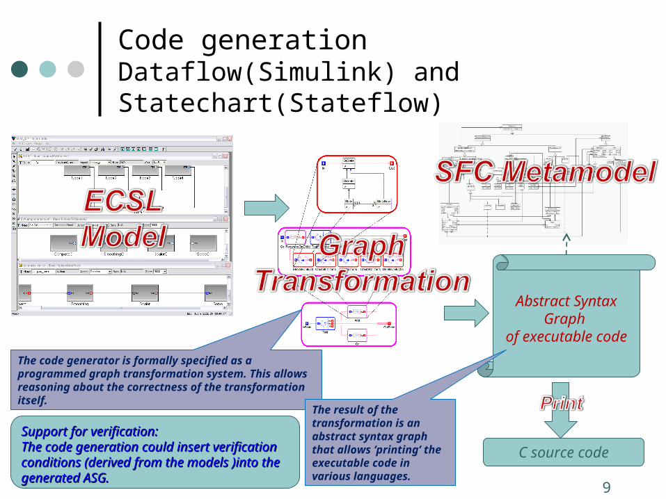
Code generationDataflow(Simulink) and Statechart(Stateflow)
The code generator is formally specified as a programmed graph transformation system. This allows reasoning about the correctness of the transformation itself.
Abstract Syntax Graph
of executable code
C source code
The result of the transformation is an abstract syntax graph that allows ‘printing’ the executable code in various languages.
Support for verification: Support for verification: The code generation could insert verification The code generation could insert verification conditions (derived from the models )into the conditions (derived from the models )into the generated ASG. generated ASG.
10
Design rationale for prototype toolchain (3)
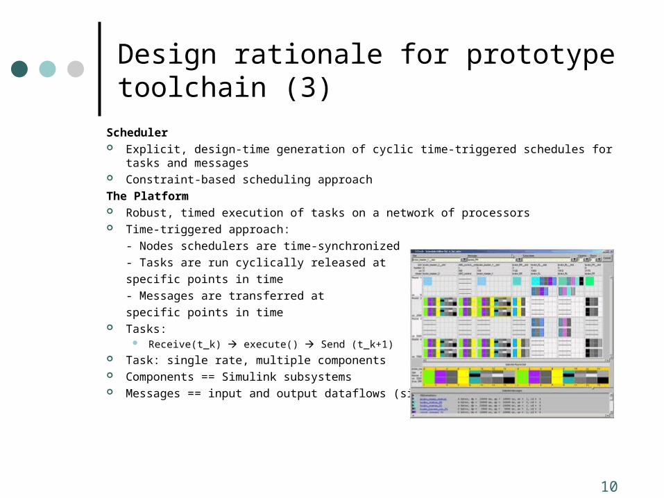
Scheduler Explicit, design-time generation of cyclic time-triggered schedules for tasks and messages Constraint-based scheduling approach
The Platform Robust, timed execution of tasks on a network of processors Time-triggered approach:
- Nodes schedulers are time-synchronized
- Tasks are run cyclically released at
specific points in time
- Messages are transferred at
specific points in time Tasks:
Receive(t_k) execute() Send (t_k+1) Task: single rate, multiple components Components == Simulink subsystems Messages == input and output dataflows (signals) of subsystems
11
Scheduling
Solution3_133228
Solution2_133228
Solution1_133228
Serialize bus messages Bus
Val2_2 <= Estimator2_7 + 0
Estimator2_6 <= Val2_2 + -2
Val2_1 <= Estimator2_5 + 0
Estimator2_4 <= Val2_1 + -2
Serialize processor Proc2
Estimator2_6 = Estimator2_7 + 25
Estimator2_5 = Estimator2_6 + 25
Estimator2_4 = Estimator2_5 + 25
Controller2_1 = Controller2_2 + 50
Serialize processor Proc1
Controller2_1 = Controller2_2 + 50
SearchConfig
Val2_2
Val2_1
Val1_0
Estimator2_7
Estimator2_6
Estimator2_5
Estimator2_4
Controller1_3
Controller2_2
Controller2_1
Estimator1_0
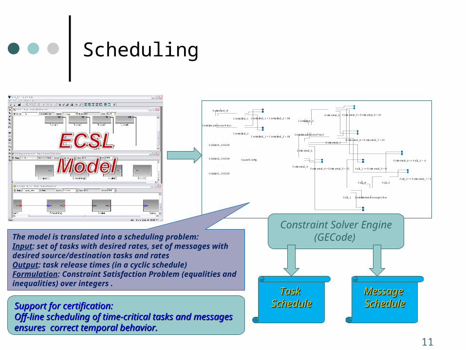
The model is translated into a scheduling problem: Input: set of tasks with desired rates, set of messages with desired source/destination tasks and ratesOutput: task release times (in a cyclic schedule)Formulation: Constraint Satisfaction Problem (equalities and inequalities) over integers .
Constraint Solver Engine(GECode)
Task Task ScheduleSchedule
Message Message ScheduleScheduleSupport for certification: Support for certification:
Off-line scheduling of time-critical tasks and messages Off-line scheduling of time-critical tasks and messages ensures correct temporal behavior. ensures correct temporal behavior.
12
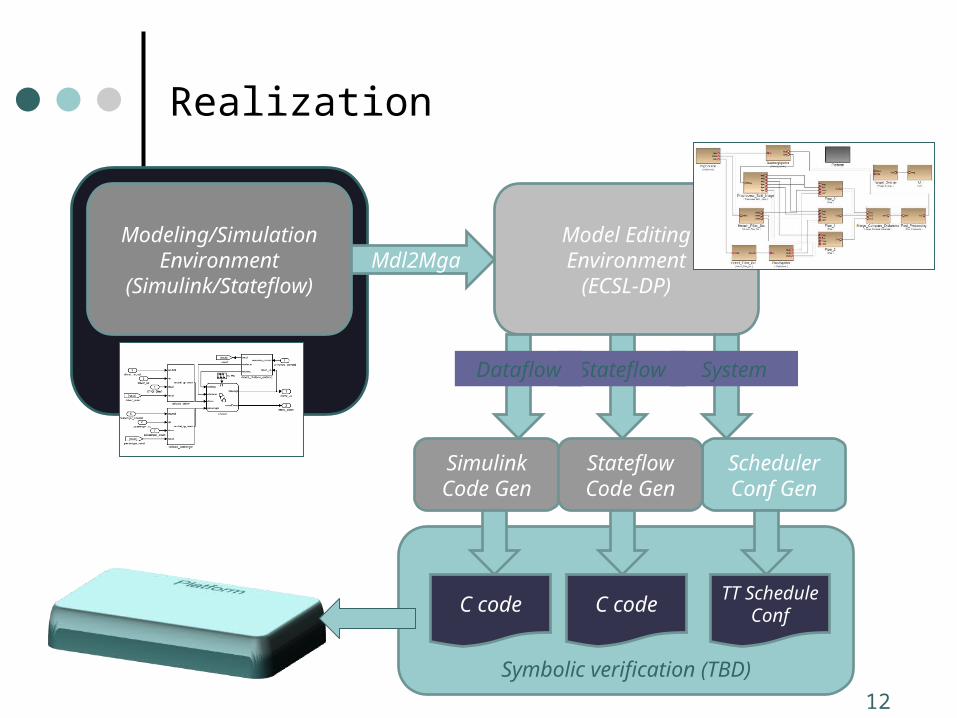
Realization
Simulation-based verification
Symbolic verification (TBD)
Model Editing Environment(ECSL-DP)
Modeling/Simulation Environment
(Simulink/Stateflow)Mdl2Mga
StateflowDataflow System
Simulink Code Gen
Scheduler Conf Gen
Stateflow Code Gen
C code C codeTT
ScheduleConf
13
Platforms
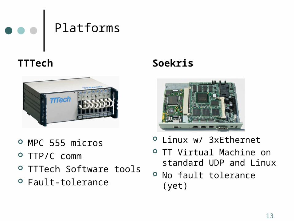
TTTech
MPC 555 micros TTP/C comm TTTech Software tools Fault-tolerance
Soekris
Linux w/ 3xEthernet TT Virtual Machine on
standard UDP and Linux No fault tolerance (yet)
14
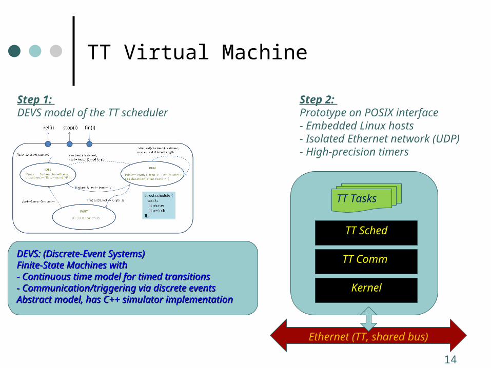
TT Virtual Machine
Step 1: DEVS model of the TT scheduler
DEVS: (Discrete-Event Systems) DEVS: (Discrete-Event Systems) Finite-State Machines withFinite-State Machines with- Continuous time model for timed transitions- Continuous time model for timed transitions- Communication/triggering via discrete events- Communication/triggering via discrete eventsAbstract model, has C++ simulator implementationAbstract model, has C++ simulator implementation
Step 2: Prototype on POSIX interface- Embedded Linux hosts - Isolated Ethernet network (UDP)- High-precision timers
Kernel
TT Comm
TT Sched
TT Tasks
Ethernet (TT, shared bus)
15
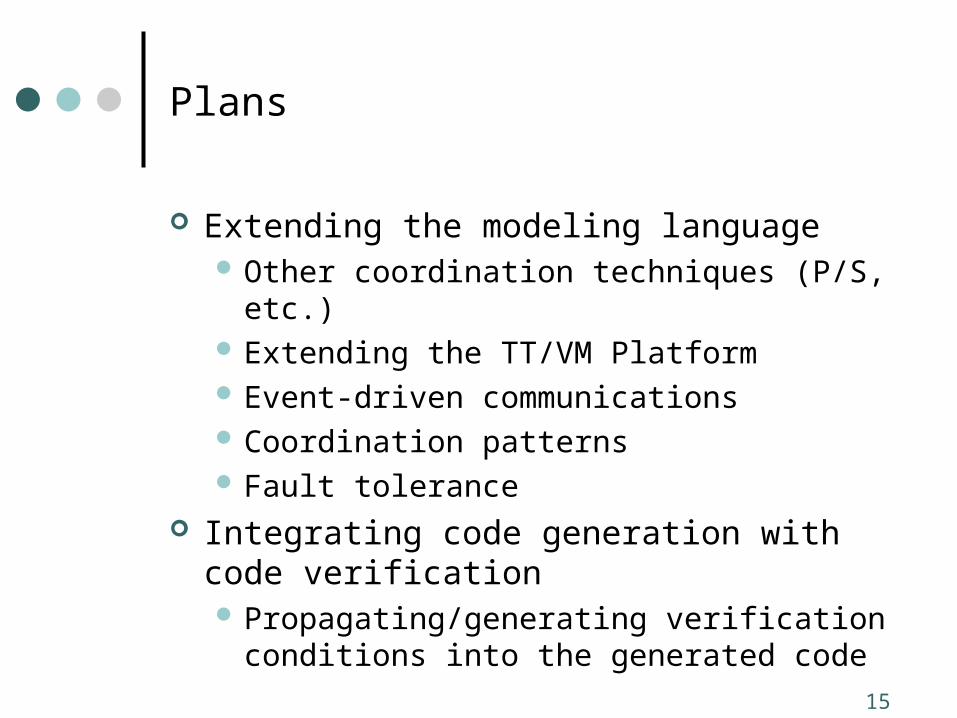
Plans
Extending the modeling language Other coordination techniques (P/S, etc.) Extending the TT/VM Platform Event-driven communications Coordination patterns Fault tolerance
Integrating code generation with code verification Propagating/generating verification conditions
into the generated code