Embed Size (px)
Citation preview

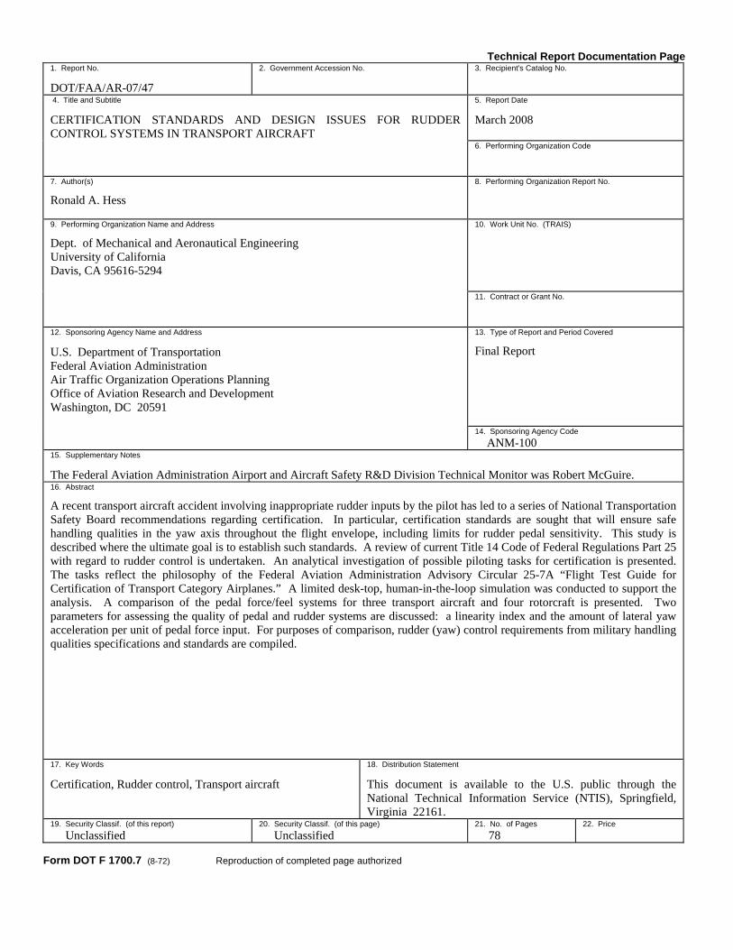
DOT/FAA/AR-07/47 Air Traffic Organization Operations Planning Office of Aviation Research and Development Washington, DC 20591
Certification Standards and Design Issues for Rudder Control Systems in Transport Aircraft March 2008 Final Report This document is available to the U.S. public through the National Technical Information Service (NTIS), Springfield, Virginia 22161.
U.S. Department of Transportation Federal Aviation Administration

NOTICE
This document is disseminated under the sponsorship of the U.S. Department of Transportation in the interest of information exchange. The United States Government assumes no liability for the contents or use thereof. The United States Government does not endorse products or manufacturers. Trade or manufacturer's names appear herein solely because they are considered essential to the objective of this report. This document does not constitute FAA certification policy. Consult your local FAA aircraft certification office as to its use. This report is available at the Federal Aviation Administration William J. Hughes Technical Center’s Full-Text Technical Reports page: actlibrary.tc.faa.gov in Adobe Acrobat portable document format (PDF).
Technical Report Documentation Page 1. Report No.
DOT/FAA/AR-07/47
2. Government Accession No. 3. Recipient's Catalog No.
4. Title and Subtitle
CERTIFICATION STANDARDS AND DESIGN ISSUES FOR RUDDER CONTROL SYSTEMS IN TRANSPORT AIRCRAFT
5. Report Date
March 2008
6. Performing Organization Code
7. Author(s)
Ronald A. Hess
8. Performing Organization Report No.
9. Performing Organization Name and Address
Dept. of Mechanical and Aeronautical Engineering University of California Davis, CA 95616-5294
10. Work Unit No. (TRAIS)
11. Contract or Grant No.
12. Sponsoring Agency Name and Address
U.S. Department of Transportation Federal Aviation Administration Air Traffic Organization Operations Planning Office of Aviation Research and Development Washington, DC 20591
13. Type of Report and Period Covered
Final Report
14. Sponsoring Agency Code ANM-100
15. Supplementary Notes
The Federal Aviation Administration Airport and Aircraft Safety R&D Division Technical Monitor was Robert McGuire. 16. Abstract
A recent transport aircraft accident involving inappropriate rudder inputs by the pilot has led to a series of National Transportation Safety Board recommendations regarding certification. In particular, certification standards are sought that will ensure safe handling qualities in the yaw axis throughout the flight envelope, including limits for rudder pedal sensitivity. This study is described where the ultimate goal is to establish such standards. A review of current Title 14 Code of Federal Regulations Part 25 with regard to rudder control is undertaken. An analytical investigation of possible piloting tasks for certification is presented. The tasks reflect the philosophy of the Federal Aviation Administration Advisory Circular 25-7A “Flight Test Guide for Certification of Transport Category Airplanes.” A limited desk-top, human-in-the-loop simulation was conducted to support the analysis. A comparison of the pedal force/feel systems for three transport aircraft and four rotorcraft is presented. Two parameters for assessing the quality of pedal and rudder systems are discussed: a linearity index and the amount of lateral yaw acceleration per unit of pedal force input. For purposes of comparison, rudder (yaw) control requirements from military handling qualities specifications and standards are compiled. 17. Key Words
Certification, Rudder control, Transport aircraft
18. Distribution Statement
This document is available to the U.S. public through the National Technical Information Service (NTIS), Springfield, Virginia 22161.
19. Security Classif. (of this report) Unclassified
20. Security Classif. (of this page) Unclassified
21. No. of Pages 78
22. Price
Form DOT F 1700.7 (8-72) Reproduction of completed page authorized
ACKNOWLEDGEMENT
The research reported herein was supported by a grant from the Federal Aviation Administration (FAA) through the Airport and Aircraft Safety R&D Division of the FAA William J. Hughes Technical Center, Atlantic City International Airport, NJ. The grant technical manager was Robert McGuire.
iii/iv

TABLE OF CONTENTS Page
EXECUTIVE SUMMARY xiii 1. INTRODUCTION 1
2. CURRENT LATERAL-DIRECTIONAL CERTIFICATION STANDARDS 2
3. THE FAA AC 25-7A FLIGHT TEST GUIDE FOR CERTIFICATION OF TRANSPORT CATEGORY AIRPLANES 5
4. SUMMARY OF PREVIOUS RESEARCH 7
5. ANALYTICAL EXAMPLE 7
5.1 Vehicle and Tasks 7 5.2 Pilot Models 8 5.3 Pedal Force/Feel Systems 9 5.4 Wings-Level Sideslip Capture Task 12 5.5 Heading-Hold Sideslip Capture Task 12 5.6 Computer Simulation 14
6. HUMAN-IN-THE-LOOP COMPUTER SIMULATION 20
6.1 Wings-Level Sideslip Capture Task 21 6.2 Heading-Hold Sideslip Capture Task 23
7. FORCE/FEEL SYSTEM DESIGN CONSIDERATIONS 24
7.1 Human Pilot Pedal Force Generation Capabilities 24 7.2 The Linearity Index 26 7.3 The Blue Angels Preloaded Center Stick 28 7.4 The Virtual Bobweight and Pedal Force per Unit of Yaw Acceleration 29
8. FORCE/FEEL SYSTEM COMPARISON 35
9. DYNAMIC FORCE/FEEL SYSTEM CONSIDERATIONS 43
10. RUDDER (YAW) CONTROL REQUIREMENTS IN MILITARY HANDLING QUALITIES SPECIFICATIONS AND STANDARDS 43
10.1 Introduction 43 10.2 Document Review 44
10.2.1 MIL-F08785 (ASG) Military Specification, Flying Qualities of Piloted Airplanes 44
v

10.2.2 Background Information and User Guide for MIL-F-8785B (ASG), Military Specification—Flying Qualities of Piloted Airplanes 48
10.2.3 Background Information and User Guide for MIL-F-8785-C, Military Specification—Flying Qualities of Piloted Airplanes 55
10.2.4 Proposed MIL Standard and Handbook—Flying Qualities of Air Vehicles, Vol. II: Proposed MIL Handbook 58
10.2.5 Military Standard—Flying Qualities of Piloted Aircraft, MIL-STD-1797A, and Military Standard—Flying Qualities of Piloted Aircraft, MIL-STD-1979 62
11. DISCUSSION 62
12. CONCLUSIONS 63
13. REFERENCES 64
vi
LIST OF FIGURES
Figure Page
1 Pilot/Vehicle System for Wings-Level and Heading-Hold Sideslip Capture Tasks for Wings-Level Task, YPψ = 0 8
2 The Structural Model of the Human Pilot 9
3 Open-Loop Pilot/Vehicle Transfer Functions for φ and β Loops in Figure 1 9
4 Competing Pedal Force/Feel Systems—Static Characteristics 10
5 Defining a Linearity Index 10
6 Dynamic Characteristics of Force/Feel System A With Sinusoidal Inputs of Different Frequency 11
7 Dynamic Characteristics of Force/Feel System B With Sinusoidal Inputs of Different Frequency 11
8 Equivalent β Command for Wings-Level Sideslip Capture Task 12
9 Bode Plot of wp ;c δ→φδ→βφ
ψ Transfer Function With Pilot Models in Place 13
10 Tracking Performance Using Pedal Force/Feel System A From Figure 4 in Wings-Level Sideslip Capture Task 14
11 Tracking Performance Using Pedal Force/Feel System B From Figure 4 in Wings-Level Sideslip Capture Task 14
12 Pedal Position for Systems A and B in Wings-Level Sideslip Capture Task 15
13 Rudder Rates for Systems A and B in Wings-Level Sideslip Capture Task 16
14 Lateral Acceleration at Pilot’s Station for Systems A and B in Wings-Level Sideslip Capture Task 16
15 Pedal Force/Feel Systems—Dynamic Characteristics for Wings-Level Sideslip Capture Task 17
16 Tracking Performance Using Pedal Force/Feel System A From Figure 4 in Heading-Hold Sideslip Capture Task 17
17 Tracking Performance Using Pedal Force/Feel System B From Figure 4 in Heading-Hold Sideslip Capture Task 18
vii
18 Pedal Position for Systems A and B in Heading-Hold Sideslip Capture Task 18
19 Rudder Rates for Systems A and B in Heading-Hold Sideslip Capture Task 19
20 Lateral Acceleration at Pilot’s Station for Systems A and B in Heading-Hold Sideslip Capture Task 19
21 Pedal Force/Feel Systems—Dynamic Characteristics in Heading-Hold Sideslip Capture Task 20
22 Display for Desktop Simulation of Wings-Level Sideslip Capture Task 21
23 Sideslip and Roll Attitude in Wings-Level Sideslip Capture Task 22
24 Pedal Position in Wing-Level Sideslip Capture Task 22
25 Rudder Rate in Wings-Level Sideslip Capture Task 23
26 Lateral Acceleration at the Pilot’s Station for Wings-Level Sideslip Task 23
27 Seated Male Using Rudder Pedals 24
28 Testing Equipment Used in Reference 10 Study 25
29 Revised Definition of an LI 27
30 (a) A Typical Force/Feel System and (b) One With a Large Preload Requiring Constant Force 28
31 A Rudder Bobweight 30
32 Bode Plots of )(δ
sr
PF
Transfer Function Showing Virtual Bobweight Effect 30
33 Pedal Sensitivity Data From Reference 15 (High Favorable Yaw Coupling) 32
34 Pedal Sensitivity Data From Reference 15 (Very High Favorable Roll Coupling) 33
35 A Rotorcraft Task Description From Reference 16 35
36 The AH-64A Apache Rotorcraft 36
37 The UH-60A Blackhawk Rotorcraft 37
38 The CH-47D Chinook Rotorcraft 37
39 The CH-53D Sea Stallion Rotorcraft 38
40 Airbus A300-600 38
viii
41 Boeing 767 38
42 Comparison of Pedal Force/Feel Systems, AH-64A and Airbus A300-600 40
43 Comparison of Pedal Force/Feel Systems, UH-60A and Airbus A300-600 40
44 Comparison of Pedal Force/Feel Systems, CH-47D and Airbus A300-600 41
45 Comparison of Pedal Force/Feel Systems, CH-53D and Airbus A300-600 41
46 Comparison of Pedal Force/Feel Systems, B-767 and Airbus A300-600 42
47 Comparison of Pedal Force/Feel Systems, Airbus A300-B2-B4 and A300-600 42
48 Effect of Force/Feel System Dynamics and Rudder Actuator Characteristics on Pedal Force vs Rudder Position for Force/Feel System B 43
ix
x
LIST OF TABLES
Table Page 1 Performance Requirements for Wings-Level Sideslip Capture Task 12
2 Performance Requirements for Heading-Hold Sideslip Capture Task 13
3 Maximum Rudder Force Capabilities of Male Pilots 24
4 Maximum Force That can be Exerted in Extension of the Leg 25
5 Means and Standard Deviations of StrengthVariables Male and Female Aviation Candidates 26
6 Means and Standard Deviations of Endurance Variables Male and Female Aviation Candidates 26
7 Linearity Indices for Selected Aircraft Pedal Force/Feel Systems 39
LIST OF ACRONYMS
AC Advisory Circular APC Aircraft-pilot coupling CFR Code of Federal Regulations FAA Federal Aviation Administration lbf Pounds of force LI Linearity index PIO Pilot-induced oscillation NTSB National Transportation Safety Board
xi/xii

EXECUTIVE SUMMARY This report provides the research necessary to address modifying Title 14 Code of Federal Regulations Part 25 to include a certification standard that will ensure safe handling qualities in the yaw axis throughout the flight envelope, including limits for rudder pedal sensitivity. This goal is accomplished through a review of the current certification standards, a summary of pertinent past research relating to the certification issue, an analytical investigation of candidate piloting tasks that could suggest revising the standard, and a discussion of methods to assess the quality of pedal and rudder control systems. Preliminary research concluded that current certification requirements for rudder force/feel systems may not be sufficient to identify potentially dangerous designs. Additonally, based on anthropometric studies on both male and female subjects, it may be advisable to limit maximum rudder pedal forces to 100 lbf in transport aircraft. A considerable difference exists in the static pedal force/feel characteristics between the Airbus A300-600 at 240 kts and six comparison aircraft. The Airbus A300-600 also exhibited the smallest pedal force/feel system linearity index of any of the comparison aircraft, and much larger yaw acceleration per pound of pedal force as compared to the Boeing 767, providing some evidence that these measures may serve as useful metrics in evaluating rudder control designs.
xiii/xiv
1. INTRODUCTION.
The probable cause of the loss of American Airlines Flight 587 in November of 2001 was established in reference 1. Among the recommendations of this report were the following directed toward the Federal Aviation Administration (FAA):
“Modify 14 Code of Federal Regulations Part 25 to include a certification standard that will ensure safe handling qualities in the yaw axis throughout the flight envelope, including limits for rudder pedal sensitivity. (A-05-46)…After the yaw axis certification standard recommended in Safety Recommendation A-04-56 has been established, review the designs of existing airplanes to determine if they meet the standard.”
The research described in this report addresses those recommendations through a review of the current certification standards, a summary of pertinent past research relating to the certification issue, an analytical investigation of candidate piloting tasks that could suggest revising the standard, and a discussion of the methods to assess the quality of pedal and rudder control systems. The candidate tasks will reflect the philosophy of FAA Advisory Circular (AC) 25-7A “Flight Test Guide for Certification of Transport Category Airplanes” [2]. The report is organized as follows: • Section 2 summarizes current certification standards as related to lateral-directional
control.
• Section 3 summarizes FAA AC 27-7A.
• Section 4 summarizes previous research by the author related to rudder force/feel system design.
• Section 5 presents a pilot/vehicle analysis and computer simulation of a particular transport aircraft rudder control system.
• Section 6 summarizes a desktop, human-in-the-loop simulation of the vehicle and task analyzed in section 5.
• Section 7 presents force/feel system design considerations pertinent to the certification process.
• Section 8 compares some existing transport aircraft and rotorcraft force/feel systems.
• Section 9 discusses dynamic force/feel system considerations.
• Section 10 compiles rudder (yaw) requirements that have appeared in military handling qualities specifications and standards.
• Section 11 discusses pertinent research results.
1
• Section 12 presents major conclusions of the study.
• Section 13 lists references cited.
2. CURRENT LATERAL-DIRECTIONAL CERTIFICATION STANDARDS.
Current Title 14 Code of Federal Regulations (CFR) Part 2 standards regarding lateral/directional controllability and maneuverability, stability, flight maneuver, and gust conditions are summarized as follows. Section 25.143, Subpart B—Flight—Controllability and Maneuverability, states that
“General. (a) The airplane must be safely controllable and maneuverable during—
(1) Takeoff; (2) Climb; (3) Level flight; (4) Descent; and Landing
(b) It must be possible to make a smooth transition from one flight condition
to any other flight condition without exceptional piloting skill, altertness, or strength, and without danger of exceeding the airplane limit-load factor under any probable operating conditions, including—
(1) The sudden failure of the critical engine (2) For airplanes with three or more engines, the sudden failure of the
second critical engine… (3) Configuration changes, including deployment or retraction of
deceleration devices.” Note: Section 25.143 (f) states that
“…the stick forces must not be so great as to make excessive demands on the pilot’s strength when maneuvering the airplane, and must not be so low that the airplane can easily be overstressed inadvertently. …and local gradients must not be so low as to result in a danger of overcontrolling,” 1
Section 25.147, Subpart B—Flight—Controllability and Maneuverability, states that
“Directional and lateral control. (a) Directional control; general. It must be possible, with the wings level to
yaw into the operative engine and to safely make a reasonably sudden change in heading of up to 15 degrees in the direction of the critical
1 The use of the word “stick” in reference to the cockpit inceptor, would appear to limit these characteristics to
those of the wheel/column.
2
inoperative engine. This must be shown at [1.3 1SRV ]2 for heading changes of up to 15 degrees (except that the heading change at which the rudder pedal forces is 150 pounds need not be exceeded), and with-- (1) (2) (3) ---------------a series of airplane configurations are defined------------- (4) (5) (6)”
Section 25.149, Subpart B—Flight—Controllability and Maneuverability, states that
“Minimum control speed. . . . (d) The rudder forces required to maintain control at VMC
3 may not exceed
150 pounds nor may it be necessary to reduce power or thrust of the operative engines. During recovery, the airplane may not assume any dangerous attitude or require exceptional piloting skill, altertness, or strength to prevent a heading change of more than 20 degrees.”
Section 25.177, Subpart B—Flight—Stability, states that
“Static lateral-directional stability. . . . (c) In straight steady sideslips, the aileron and rudder control movements and
forces must be substantially proportional to the angle of sideslip in a stable sense; and the factor of proportionality must lie between limits found necessary for safe operation throughout the range of sideslip angles appropriate for operation of the airplane…Compliance with this paragraph must be demonstrated for all landing gear and flap positions and symmetrical power conditions at speeds from [1.3 ] to VFE,1SRV 4 VLE
5 or VFC/MFC
6, as appropriate.
2 1.3 times reference stall speed at the specified condition 3 Minimum control speed with the critical engine inoperative 4 Maximum flap extended speed 5 Maximum landing gear extended speed 6 Maximum speed for stability characteristics
3
(d) The rudder gradients must meet the requirements of paragraph (c) at speeds between VMO/MMO
7 and VFC/MFC except that the dihedral effect (aileron deflections opposite the corresponding rudder input) may be negative provided the divergence is gradual, easily recognized, and easily controlled by the pilot.”
Section 25.181, Subpart B—Flight—Stability, states that
“Dynamic Stability. . . . (b) Any combined lateral-directional oscillations (“Dutch roll”) occurring
between [1.13 VSR] and maximum allowable speed appropriate to the configuration of the airplane must be positively damped with controls free, and must be controllable with normal use of the primary controls without requiring exceptional pilot skill.”
Section 25.351, Subpart C—Structure—Flight Maneuver and Gust Conditions, states that
“[Yaw maneuver] conditions [The airplane must be designed for loads resulting from yaw maneuver conditions specified in paragraphs (a) through (d) of this section at speeds from VMC to VD
8. Unbalanced aerodynamic moments about the center of gravity must be reacted in a rational or conservative manner considering the airplane inertia forces. In computing the tail loads the yawing velocity may be assumed to be zero. (a) With the airplane in unaccelerated flight at zero yaw, it is assumed that the
cockpit rudder is suddenly displace to achieve the resulting rudder deflection as limited by: (1) The control system on control surface stops; or (2) A limit pilot force of 300 pounds from VMC to VA
9 and 200 pounds
from VC/MC10 to VD/MD with a linear variation between VA and
VC/MC. (b) With the cockpit rudder deflected so as always to maintain the maximum
rudder deflection available within the limitations specified in paragraph (a) of this section, it is assumed that the airplane yaws to the overswing sideslip angle.
(c) With the airplane yawed to the static equilibrium sideslip angle, it is assumed that the cockpit rudder control is held so as to achieve the
7 Maximum operating limit speed 8 Design diving speed 9 Design maneuvering speed 10 Design cruising speed
4

maximum rudder deflection available within the limitations specified in paragraph (a) of this section.
(d) With the airplane yawed to the static equilibrium sideslip angle of paragraph (c) of this section, it is assumed that the cockpit rudder control is suddenly returned to neutral].”
The 14 CFR Part 25 regulations dealing with lateral/directional airplane characteristics summarized in the preceding paragraphs deal only in very general terms with closed-loop pilot/vehicle behavior [3]. Requirements addressing such behavior are typically couched in broad terms such as “…must be controllable with normal use of the primary controls without requiring exceptional pilot skill” (25.147(a)). The introduction of AC 25-7A in 1998 marked a departure from previous regulatory documents in that special attention was paid to closed-loop pilot/vehicle behavior. Of course, like all AC material, these guidelines are not mandatory and do not constitute regulations. Pertinent sections of AC 25-7A are discussed below.
3. THE FAA AC 25-7A FLIGHT TEST GUIDE FOR CERTIFICATION OF TRANSPORT CATEGORY AIRPLANES.
This section focuses on summarizing those sections of AC 25-7A that addressed the Part 25 sections mentioned above, i.e., 25.143, 147, 149, 177, 181, and 351. Again, it is lateral/directional pilot/vehicle behavior that is of interest, and particularly, that which involves rudder control. In addressing 14 CFR 25.143, AC 25-7A explicitly discusses aircraft-pilot coupling (APC) pilot-induced oscillation (PIO). In particular, it is stated:
“…service experience has shown that compliance with only the quantitative, open-loop (pilot-out-of-the-loop) requirements does not guarantee that the required levels of flying qualities are achieved. Therefore, in order to ensure that the airplane has achieved the flying qualities required by §§ 25.143(a) and (b), the airplane must be evaluated by test pilots conducting high-gain (wide-bandwidth) closed-loop tasks to determine that the potential of encountering adverse APC tendencies is minimal. For the most part, these tasks must be performed in actual flight. However, for conditions that are considered too dangerous to attempt in actual flight…the closed loop evaluation tasks may be performed using a motion base high fidelity simulator if it can be validated for the flight conditions of interest.”
AC 25-7A goes into considerable detail on Procedures (Flight Test). The comments made are pertinent to all control inputs (axes) and are directed toward specific, closed-loop piloting tasks. Statements include:
“Evaluation of the actual task performance achieved…is not recommended as a measure of proof of compliance. Only the pilot's rating of the APC characteristics is needed…
5

Tasks for a specific certification project should be based upon operational situations, flight testing maneuvers, or service difficulties that have produced APC events. Tasks described here may be useful in any given evaluation and have proven to be operationally significant in the past. It is not intended that these are the only tasks that may be used…Other tasks may be developed and used as appropriate. For example, some manufacturers have used formation tracking tasks successfully in the investigation of these tendencies.”
AC 25-7A also goes into considerable detail in assessing an aircraft’s APC characteristics. This includes the description of specific maneuvers and tasks to be performed by evaluation pilots, i.e., “capture” tasks and “fine-tracking” tasks. The former are intended to evaluate handling qualities in gross acquisition tasks, while the latter imply tasks such as flying in a turbulent atmosphere. AC 25-7A describes APC rating criteria, using a rating scale similar to that used in military handling qualities evaluations of APC characteristics.
In addressing directional control in 14 CFR 25-147, AC 25-7A suggests the following test procedure (task):
“The airplane should be trimmed in level flight at the most critical altitude in accordance with §25.21 (c).11 Reasonably sudden changes in heading to the left and right using ailerons to maintain approximately wings-level flight should be made demonstrating a change of up to 15 degrees or that at which 150 lbs. of rudder force is required. The airplane should be controllable and free from any hazardous characteristics during this maneuver.”
In addressing 14 CFR 25.149, AC 25-7A goes into considerable detail in discussing minimum control speed requirements. There is little specific information concerning closed-loop rudder control. Similarly, there is little specific information concerning closed-loop rudder control in AC 25-7A in dealing with 14 CFR 25.177. In addressing 14 CFR 25.181, AC 25-7A states that
“A typical test for lateral-directional dynamic stability is accomplished by a rudder doublet input at a rate and amplitude that will excite the lateral-directional response (“Dutch Roll”). The control input should be in phase with the airplane's oscillatory response.”
Here, there is no mention of pilot closed-loop tracking. Rather, the rudder input is used strictly as a means to excite the dominant lateral/directional model of the aircraft.
11 This article states “The controllability, stability, trim, and stalling characteristics of the airplane must be shown for
each altitude up to the maximum expected in operation.”
6

AC 25-7A does not directly address 14 CFR 25.351. 4. SUMMARY OF PREVIOUS RESEARCH.
An analytical study augmented by some limited desk-top simulation was summarized in reference 4. The major conclusions of this research are summarized below. • A system survey of possible manual loop closure that could be employed by the pilot
using rudder control led to an examination of two tracking strategies that could occur in large roll upsets and deliberate sideslip excursions. These strategies were (a) coordinated use of aileron and rudder inputs and (b) wings-level sideslip captures.
• Using bandwidth/phase delay measures, the combined use of aileron and rudder inputs was predicted to result in low obtainable bandwidths in roll-attitude control. Although no bandwidth boundaries have been established for acceptable handling qualities in tasks involving coordinated use of aileron and rudder, the relatively small bandwidth values suggest poor handling qualities in such tasks in anything save low-bandwidth operations.
• The analysis suggested that rudder force/feel systems with large sensitivities (or equivalently, low force gradients) could precipitate PIOs when combined use of ailerons and rudder were employed. This susceptibility could be attributed to large lateral accelerations occurring at the pilot’s station.
• The analysis suggested that wings-level sideslip captures might serve as a useful pilot-in-the-loop flight simulation task to investigate handling qualities issues involving rudder control.
• The handling qualities and flight safety implications of high-gain, closed-loop tracking using combined aileron and rudder inputs that were suggested in the analysis were reflected in the desktop simulation.
5. ANALYTICAL EXAMPLE.
5.1 VEHICLE AND TASKS.
The following example follows closely to the analytical study discussed in reference 4. However, in the computer simulation of the pilot/vehicle system, a more realistic representation of the force/feel nonlinear characteristics was undertaken than in reference 4. The aircraft chosen for study was the DC-8 vehicle with stability derivatives defined for flight condition “8002” in reference 5, corresponding to an airspeed of 468.2 ft/sec and an altitude of 15,000 ft. A yaw damper was added to the basic airframe that increased the damping of the dutch-roll mode from 0.11 to 0.4. Second-order actuators were included with transfer functions given in shorthand notation by
]2020)707.0(2[
2022
2
++=
δδ
=δδ
sscc a
a
r
r rad/rad (1)
7

Actuator rate and amplitude limits also were included, as indicated below. aileron: amplitude limit = ±20 deg rate limit = ±45 deg/sec rudder: amplitude limit = ±15 deg rate limit = ±60 deg/sec The wings-level sideslip capture, mentioned in the preceding sections, and a heading-hold sideslip capture task were chosen for study. 5.2 PILOT MODELS.
Figure 1 is a block diagram representation of the hypothesized pilot/vehicle feedback structure for both tasks. Structural models of the human pilot were used in both the roll attitude and sideslip loops [4]. The form of the structural model is shown in figure 2. The structural model parameters were chosen, as discussed in reference 4. In nearly all applications, the outer-loop function Ye in figure 2 was a simple gain, i.e., Ye = Ke. Nominal crossover frequencies of 2 rad/sec were chosen initially for each loop, clearly indicating that the models met the dictates of the crossover model of the human pilot [6]. Figure 3 shows the Bode plots for the resulting open-loop pilot/vehicle transfer functions.
Figure 1. Pilot/Vehicle System for Wings-Level and Heading-Hold Sideslip Capture Tasks for
Wings-Level Task, YPψ = 0
8
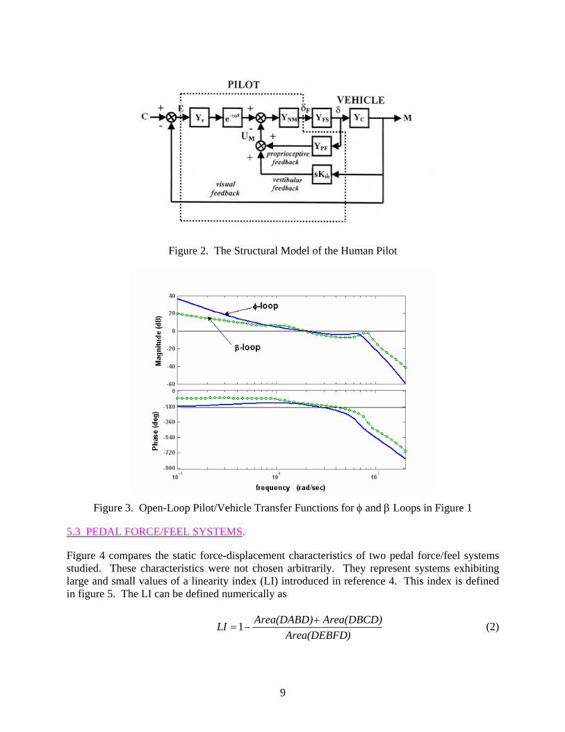
Figure 2. The Structural Model of the Human Pilot
Figure 3. Open-Loop Pilot/Vehicle Transfer Functions for φ and β Loops in Figure 1
5.3 PEDAL FORCE/FEEL SYSTEMS.
Figure 4 compares the static force-displacement characteristics of two pedal force/feel systems studied. These characteristics were not chosen arbitrarily. They represent systems exhibiting large and small values of a linearity index (LI) introduced in reference 4. This index is defined in figure 5. The LI can be defined numerically as
)Area(DEBFD
Area(DBCD)Area(DABD)LI +−=1 (2)
9
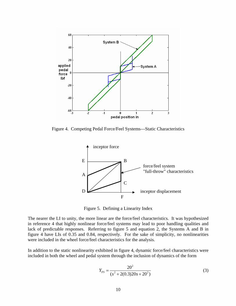
Figure 4. Competing Pedal Force/Feel Systems—Static Characteristics
inceptor force
A
B
C
D
E
F inceptor displacement
force/feel system "full-throw" characteristics
Figure 5. Defining a Linearity Index
The nearer the LI to unity, the more linear are the force/feel characteristics. It was hypothesized in reference 4 that highly nonlinear force/feel systems may lead to poor handling qualities and lack of predictable responses. Referring to figure 5 and equation 2, the Systems A and B in figure 4 have LIs of 0.35 and 0.84, respectively. For the sake of simplicity, no nonlinearities were included in the wheel force/feel characteristics for the analysis. In addition to the static nonlinearity exhibited in figure 4, dynamic force/feel characteristics were included in both the wheel and pedal system through the inclusion of dynamics of the form
)2020)3.0(2(
2022
2
++=
ssYFS (3)
10
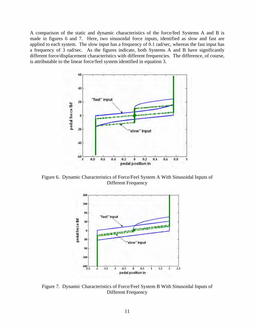
A comparison of the static and dynamic characteristics of the force/feel Systems A and B is made in figures 6 and 7. Here, two sinusoidal force inputs, identified as slow and fast are applied to each system. The slow input has a frequency of 0.1 rad/sec, whereas the fast input has a frequency of 3 rad/sec. As the figures indicate, both Systems A and B have significantly different force/displacement characteristics with different frequencies. The difference, of course, is attributable to the linear force/feel system identified in equation 3.
Figure 6. Dynamic Characteristics of Force/Feel System A With Sinusoidal Inputs of Different Frequency
Figure 7. Dynamic Characteristics of Force/Feel System B With Sinusoidal Inputs of Different Frequency
11
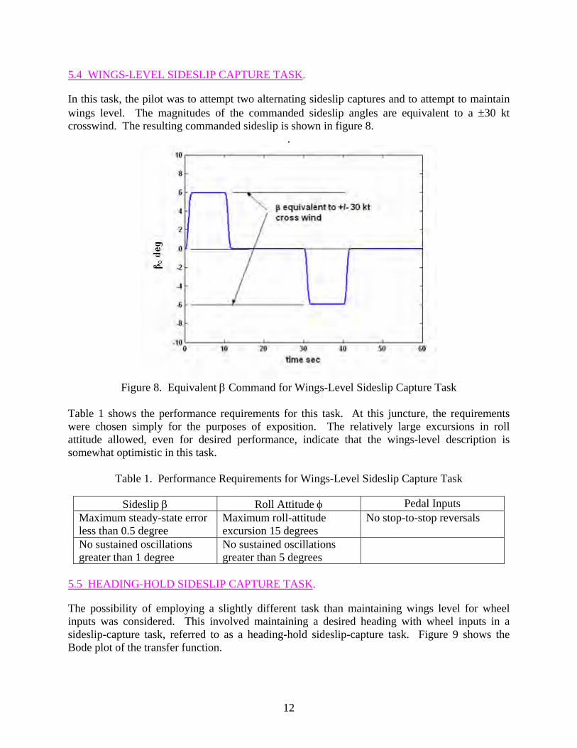
5.4 WINGS-LEVEL SIDESLIP CAPTURE TASK.
In this task, the pilot was to attempt two alternating sideslip captures and to attempt to maintain wings level. The magnitudes of the commanded sideslip angles are equivalent to a ±30 kt crosswind. The resulting commanded sideslip is shown in figure 8.
.
Figure 8. Equivalent β Command for Wings-Level Sideslip Capture Task
Table 1 shows the performance requirements for this task. At this juncture, the requirements were chosen simply for the purposes of exposition. The relatively large excursions in roll attitude allowed, even for desired performance, indicate that the wings-level description is somewhat optimistic in this task.
Table 1. Performance Requirements for Wings-Level Sideslip Capture Task
Sideslip β Roll Attitude φ Pedal Inputs Maximum steady-state error less than 0.5 degree
Maximum roll-attitude excursion 15 degrees
No stop-to-stop reversals
No sustained oscillations greater than 1 degree
No sustained oscillations greater than 5 degrees
5.5 HEADING-HOLD SIDESLIP CAPTURE TASK.
The possibility of employing a slightly different task than maintaining wings level for wheel inputs was considered. This involved maintaining a desired heading with wheel inputs in a sideslip-capture task, referred to as a heading-hold sideslip-capture task. Figure 9 shows the Bode plot of the transfer function.
12
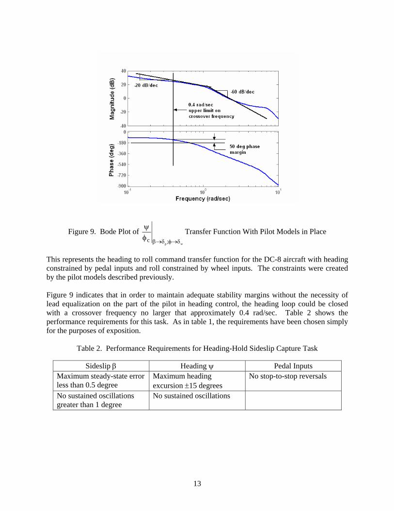
Figure 9. Bode Plot of wp ;c δ→φδ→βφ
ψ Transfer Function With Pilot Models in Place
This represents the heading to roll command transfer function for the DC-8 aircraft with heading constrained by pedal inputs and roll constrained by wheel inputs. The constraints were created by the pilot models described previously. Figure 9 indicates that in order to maintain adequate stability margins without the necessity of lead equalization on the part of the pilot in heading control, the heading loop could be closed with a crossover frequency no larger that approximately 0.4 rad/sec. Table 2 shows the performance requirements for this task. As in table 1, the requirements have been chosen simply for the purposes of exposition.
Table 2. Performance Requirements for Heading-Hold Sideslip Capture Task
Sideslip β Heading ψ Pedal Inputs Maximum steady-state error less than 0.5 degree
Maximum heading excursion ±15 degrees
No stop-to-stop reversals
No sustained oscillations greater than 1 degree
No sustained oscillations
13
5.6 COMPUTER SIMULATION.
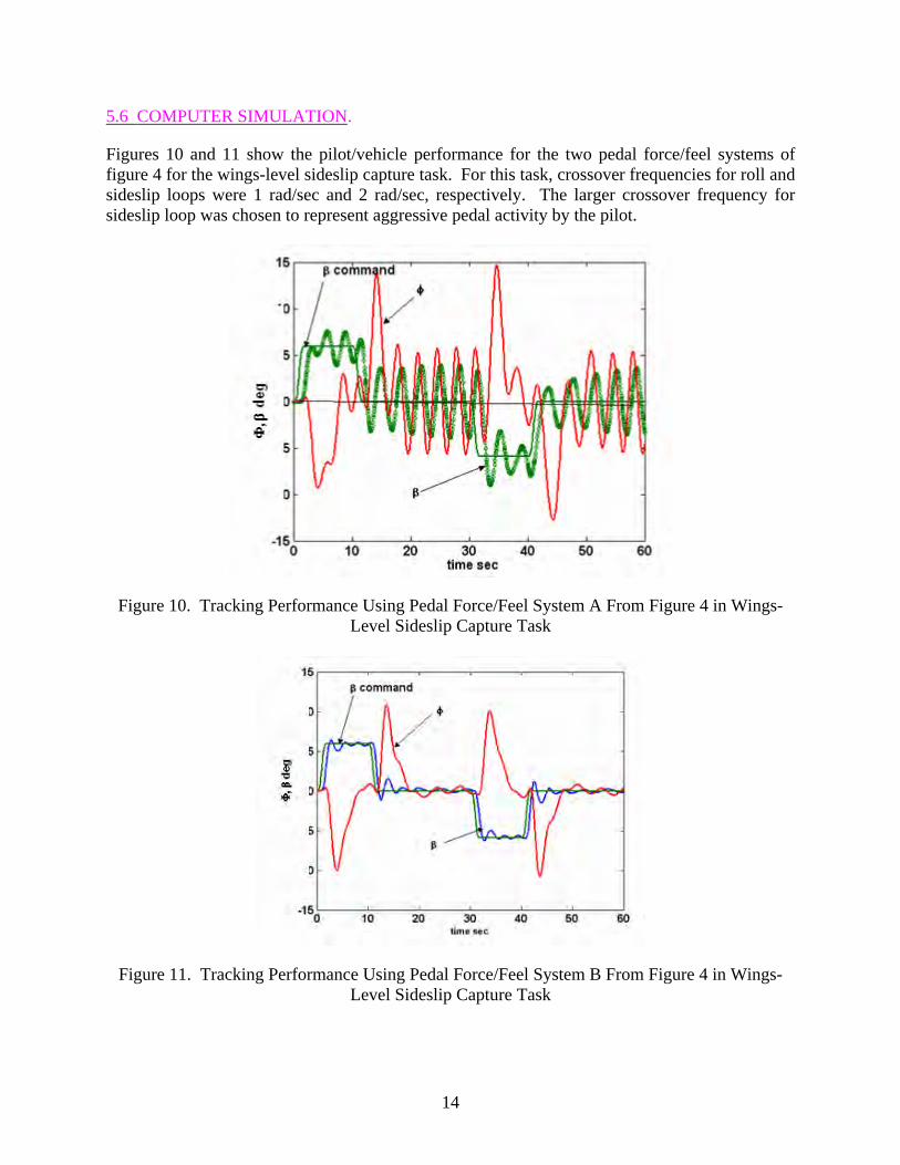
Figures 10 and 11 show the pilot/vehicle performance for the two pedal force/feel systems of figure 4 for the wings-level sideslip capture task. For this task, crossover frequencies for roll and sideslip loops were 1 rad/sec and 2 rad/sec, respectively. The larger crossover frequency for sideslip loop was chosen to represent aggressive pedal activity by the pilot.
Figure 10. Tracking Performance Using Pedal Force/Feel System A From Figure 4 in Wings-Level Sideslip Capture Task
Figure 11. Tracking Performance Using Pedal Force/Feel System B From Figure 4 in Wings-Level Sideslip Capture Task
14
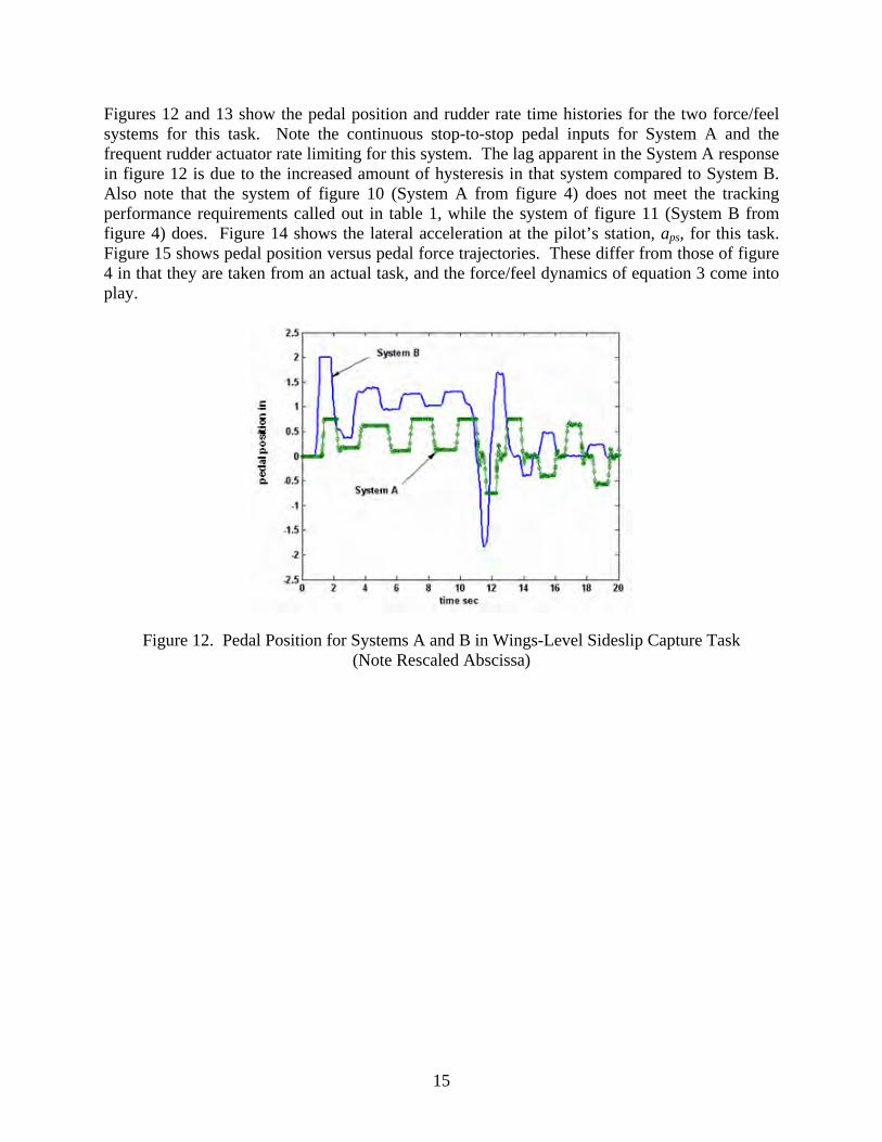
Figures 12 and 13 show the pedal position and rudder rate time histories for the two force/feel systems for this task. Note the continuous stop-to-stop pedal inputs for System A and the frequent rudder actuator rate limiting for this system. The lag apparent in the System A response in figure 12 is due to the increased amount of hysteresis in that system compared to System B. Also note that the system of figure 10 (System A from figure 4) does not meet the tracking performance requirements called out in table 1, while the system of figure 11 (System B from figure 4) does. Figure 14 shows the lateral acceleration at the pilot’s station, aps, for this task. Figure 15 shows pedal position versus pedal force trajectories. These differ from those of figure 4 in that they are taken from an actual task, and the force/feel dynamics of equation 3 come into play.
Figure 12. Pedal Position for Systems A and B in Wings-Level Sideslip Capture Task (Note Rescaled Abscissa)
15

Figure 13. Rudder Rates for Systems A and B in Wings-Level Sideslip Capture Task (Note Rescaled Abscissa)
Figure 14. Lateral Acceleration at Pilot’s Station for Systems A and B in Wings-Level Sideslip Capture Task
16

Figure 15. Pedal Force/Feel Systems—Dynamic Characteristics for Wings-Level Sideslip Capture Task
It is noteworthy that the LI defined in equation 2 and figure 5 appears to be a sensitive indicator of the overall acceptability of force/feel system characteristics. Figures 16-21 show computer simulation results for the heading-hold sideslip capture task that correspond to figures 10-15 for the wings-level sideslip capture task.
Figure 16. Tracking Performance Using Pedal Force/Feel System A From Figure 4 in Heading-Hold Sideslip Capture Task
17
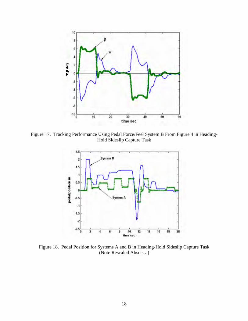
Figure 17. Tracking Performance Using Pedal Force/Feel System B From Figure 4 in Heading-Hold Sideslip Capture Task
Figure 18. Pedal Position for Systems A and B in Heading-Hold Sideslip Capture Task (Note Rescaled Abscissa)
18
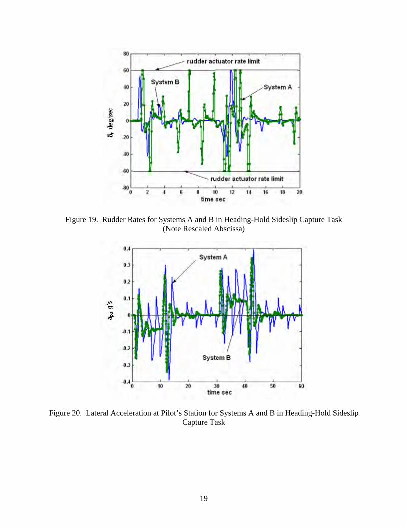
Figure 19. Rudder Rates for Systems A and B in Heading-Hold Sideslip Capture Task (Note Rescaled Abscissa)
Figure 20. Lateral Acceleration at Pilot’s Station for Systems A and B in Heading-Hold Sideslip Capture Task
19
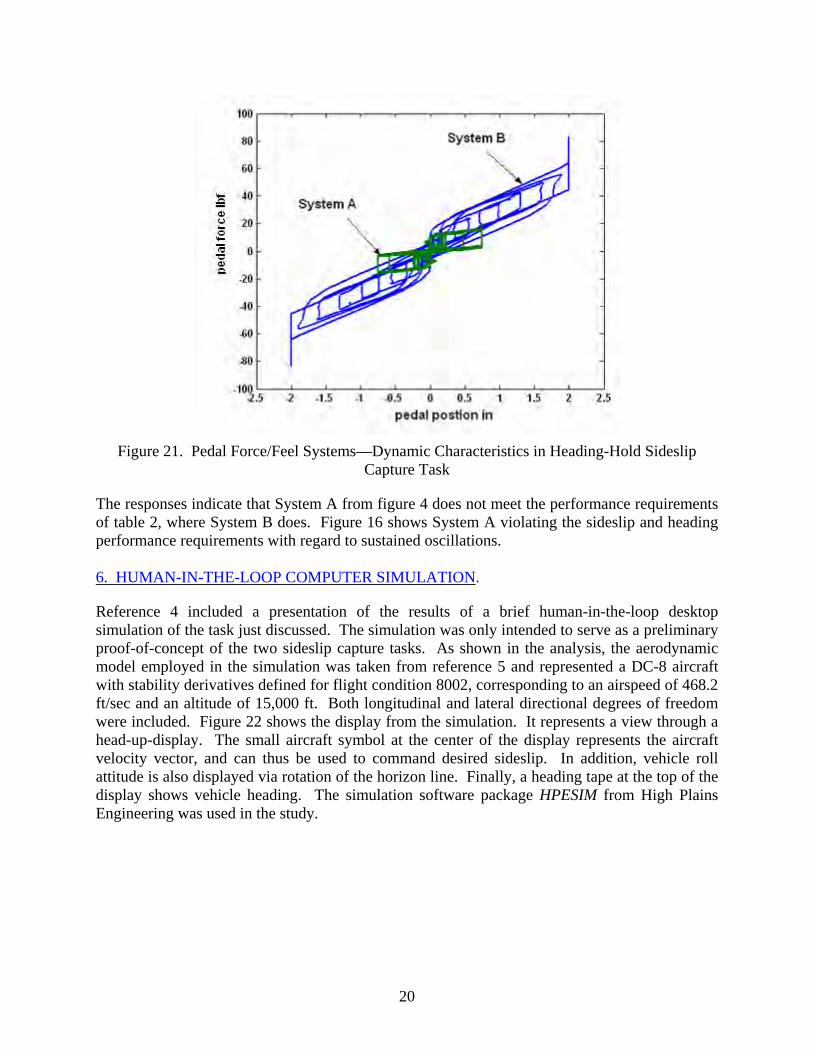
Figure 21. Pedal Force/Feel Systems—Dynamic Characteristics in Heading-Hold Sideslip
Capture Task
The responses indicate that System A from figure 4 does not meet the performance requirements of table 2, where System B does. Figure 16 shows System A violating the sideslip and heading performance requirements with regard to sustained oscillations. 6. HUMAN-IN-THE-LOOP COMPUTER SIMULATION.
Reference 4 included a presentation of the results of a brief human-in-the-loop desktop simulation of the task just discussed. The simulation was only intended to serve as a preliminary proof-of-concept of the two sideslip capture tasks. As shown in the analysis, the aerodynamic model employed in the simulation was taken from reference 5 and represented a DC-8 aircraft with stability derivatives defined for flight condition 8002, corresponding to an airspeed of 468.2 ft/sec and an altitude of 15,000 ft. Both longitudinal and lateral directional degrees of freedom were included. Figure 22 shows the display from the simulation. It represents a view through a head-up-display. The small aircraft symbol at the center of the display represents the aircraft velocity vector, and can thus be used to command desired sideslip. In addition, vehicle roll attitude is also displayed via rotation of the horizon line. Finally, a heading tape at the top of the display shows vehicle heading. The simulation software package HPESIM from High Plains Engineering was used in the study.
20

Figure 22. Display for Desktop Simulation of Wings-Level Sideslip Capture Task
Aileron inputs were created by lateral stick deflection, with rudder inputs created by rotating the stick about a vertical axis. When viewed from above, a clockwise rotation of the joystick was equivalent to right pedal depressed. The simulation software used requires inputs from a single joystick, thus separate pedals to provide rudder inputs were not acceptable. Displacement thresholds for wheel and pedal inputs were 20% and 10% of full deflections, respectively, created in software. Although longitudinal aircraft dynamics were included in the simulation, no column inputs were allowed. The natural aircraft short period and phugoid motions were mitigated by creating a high-gain, pitch-attitude stability augmentation system. Because of the limitations of using a small, commercially available joystick, the particular force/feel characteristics of the preceding analysis were not duplicated in the simulation. 6.1 WINGS-LEVEL SIDESLIP CAPTURE TASK.
Figure 23 shows a typical sideslip response to an attempt at -5 degree sideslip capture and a return to zero sideslip. This would correspond to the second part of the alternating sideslip command of figure 6. The capture takes approximately 5 seconds, with the return to zero sideslip taking about 5 seconds. Figures 24 and 25 show the rudder pedal and rudder surface rates. Note the qualitative similarity between the responses in figures 8 and 24 and 9 and 25 for a negative sideslip capture. The maximum lateral acceleration values apparent in figure 26 are considerably smaller than the values in figure 17 for System B. This is attributable to the less aggressive sideslip response of figure 23 compared to that of figure 11.
21

Figure 23. Sideslip and Roll Attitude in Wings-Level Sideslip Capture Task
Figure 24. Pedal Position in Wing-Level Sideslip Capture Task
22
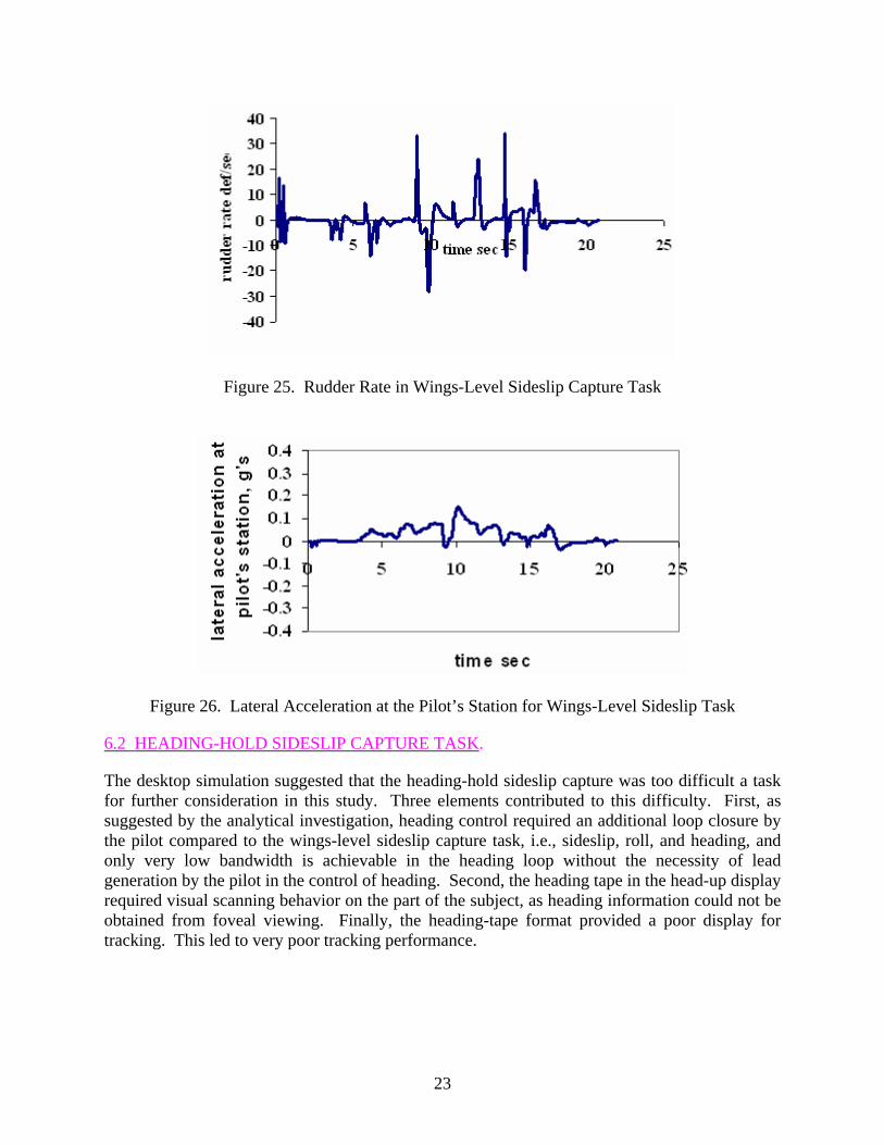
Figure 25. Rudder Rate in Wings-Level Sideslip Capture Task
Figure 26. Lateral Acceleration at the Pilot’s Station for Wings-Level Sideslip Task
6.2 HEADING-HOLD SIDESLIP CAPTURE TASK.
The desktop simulation suggested that the heading-hold sideslip capture was too difficult a task for further consideration in this study. Three elements contributed to this difficulty. First, as suggested by the analytical investigation, heading control required an additional loop closure by the pilot compared to the wings-level sideslip capture task, i.e., sideslip, roll, and heading, and only very low bandwidth is achievable in the heading loop without the necessity of lead generation by the pilot in the control of heading. Second, the heading tape in the head-up display required visual scanning behavior on the part of the subject, as heading information could not be obtained from foveal viewing. Finally, the heading-tape format provided a poor display for tracking. This led to very poor tracking performance.
23

7. FORCE/FEEL SYSTEM DESIGN CONSIDERATIONS.
7.1 HUMAN PILOT PEDAL FORCE GENERATION CAPABILITIES.
Reference 7 provides a brief list of the maximum rudder forces that the pilot can exert for various rudder positions. The source of this data was from reference 8, and the results are shown in table 3. It must be emphasized that this data is 60 years old and undoubtedly refers to male pilots only. The table indicates a rudder travel of 3.75 inches from neutral with maximum applied force capability well in excess of 400 pounds of force (lbf) from the neutral position.
Table 3. Maximum Rudder Force Capabilities of Male Pilots (from Reference 7)
Rudder Pedal Position
Distance of Pedal From Seat Back
(in.) Applied Force
(lbf) Back 31 246
Neutral 34.75 424 Forward 38.5 334
Table 4 and figure 27, both taken from reference 9, provide more data in regard to the operation of rudder pedals. Reference 9 further recommends limiting maximum forces to 150 lbf for a full-leg operation.
Figure 27. Seated Male Using Rudder Pedals [9]
24
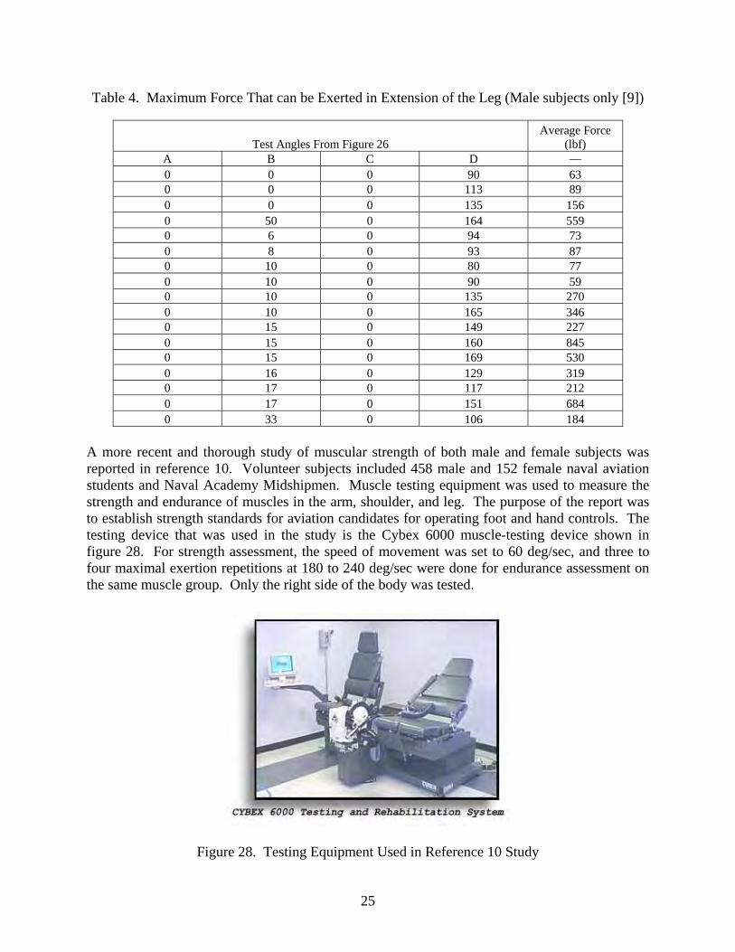
Table 4. Maximum Force That can be Exerted in Extension of the Leg (Male subjects only [9])
Test Angles From Figure 26 Average Force
(lbf) A B C D — 0 0 0 90 63 0 0 0 113 89 0 0 0 135 156 0 50 0 164 559 0 6 0 94 73 0 8 0 93 87 0 10 0 80 77 0 10 0 90 59 0 10 0 135 270 0 10 0 165 346 0 15 0 149 227 0 15 0 160 845 0 15 0 169 530 0 16 0 129 319 0 17 0 117 212 0 17 0 151 684 0 33 0 106 184
A more recent and thorough study of muscular strength of both male and female subjects was reported in reference 10. Volunteer subjects included 458 male and 152 female naval aviation students and Naval Academy Midshipmen. Muscle testing equipment was used to measure the strength and endurance of muscles in the arm, shoulder, and leg. The purpose of the report was to establish strength standards for aviation candidates for operating foot and hand controls. The testing device that was used in the study is the Cybex 6000 muscle-testing device shown in figure 28. For strength assessment, the speed of movement was set to 60 deg/sec, and three to four maximal exertion repetitions at 180 to 240 deg/sec were done for endurance assessment on the same muscle group. Only the right side of the body was tested.
Figure 28. Testing Equipment Used in Reference 10 Study
25

Three major muscle groups in the body were tested because of their involvement in performing critical occupational tasks in aviation: the large muscles of the upper leg that extend and flex the knee (quadriceps and hamstrings), the muscles acting on the shoulder joint to cause rotation, and the elbow extensors and flexors (biceps and triceps). Here, attention will focus on the results for the leg and knee. Tables 5 and 6 summarize the pertinent data.
Table 5. Means and Standard Deviations of StrengthVariables Male and Female Aviation Candidates [10]
Male Female Limb: Knee Mean Standard Deviation Mean Standard Deviation
Flexion Peak torque (ft-lbf) 99.62 17.84 64.06 11.94 TAE (ft-lbf) 7.52 1.79 4.71 1.11 Extension Peak torque (ft-lbf) 172.12 30.47 113.2 20.47 TAE (ft-lbf) 11.68 2.62 7.03 1.52
TAE = Total Acceleration Energy
Table 6. Means and Standard Deviations of Endurance Variables Male and Female Aviation Candidates [10]
Male Female Limb: Knee Mean Standard Deviation Mean Standard Deviation
Flexion Total work (ft-lbf) 80.79 16.31 52.82 12.11 Average power (W) 203.13 41.6 136.06 29.47 Extension Total work (ft-lbf) 123.11 23.02 78.03 16.32 Average power (W) 303.09 64.94 196.13 41.41
As the tables indicate, there are significant differences between male and female subjects in both strength and endurance of the quadriceps and hamstrings. In terms of strength, the female candidates exhibited only about 65% of that of their male counterparts. This would suggest that maximum pedal forces required in any force/feel system be reduced from the 150 lbf recommended in reference 9 on the basis of male subjects to approximately 100 lbf for both male and female pilots. Similar comparisons of male and female strength can be found in reference 11. 7.2 THE LINEARITY INDEX.
The LI introduced in reference 4 and defined in equation 2 assumed that the breakout and friction forces were identical and that the friction force did not affect breakout. This means that the force versus displacement graphs were parallelograms in the first and third quadrants. Figure 29 shows a more realistic representation. The remaining constraint in figure 29 is that the slopes of
26
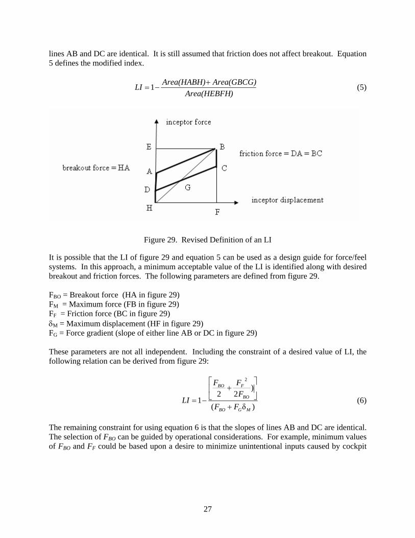
lines AB and DC are identical. It is still assumed that friction does not affect breakout. Equation 5 defines the modified index.
)Area(HEBFH
Area(GBCG)Area(HABH)LI +−=1 (5)
Figure 29. Revised Definition of an LI
It is possible that the LI of figure 29 and equation 5 can be used as a design guide for force/feel systems. In this approach, a minimum acceptable value of the LI is identified along with desired breakout and friction forces. The following parameters are defined from figure 29. FBO = Breakout force (HA in figure 29) FM = Maximum force (FB in figure 29) FF = Friction force (BC in figure 29) δM = Maximum displacement (HF in figure 29) FG = Force gradient (slope of either line AB or DC in figure 29) These parameters are not all independent. Including the constraint of a desired value of LI, the following relation can be derived from figure 29:
)δ(
)22
1
2
MGBO
BO
FBO
FFFFF
LI+
⎥⎦
⎤⎢⎣
⎡+
−= (6)
The remaining constraint for using equation 6 is that the slopes of lines AB and DC are identical. The selection of FBO can be guided by operational considerations. For example, minimum values of FBO and FF could be based upon a desire to minimize unintentional inputs caused by cockpit
27
accelerations or pilot changes in seating posture. Now assume that it is desired to obtain LI = 0.8, with FBO = 10 lbf and FF = 10 lbf. Equation 6 will yield lbf40δ =MGF (7)
a value well below the 100 lbf suggested in section 7. The designer can now choose a force gradient FG. The selection of this gradient will determine the lateral acceleration in g’s at the pilot’s station per pound of pedal force beyond breakout at each flight condition. As seen in section 7.4, a maximum value of this ratio is recommended. This maximum value would then yield a desired minimum value of FG. If, for example, the resulting minimum FG =15 lbf/in, then δM = 2.67″. 7.3 THE BLUE ANGELS PRELOADED CENTER STICK.
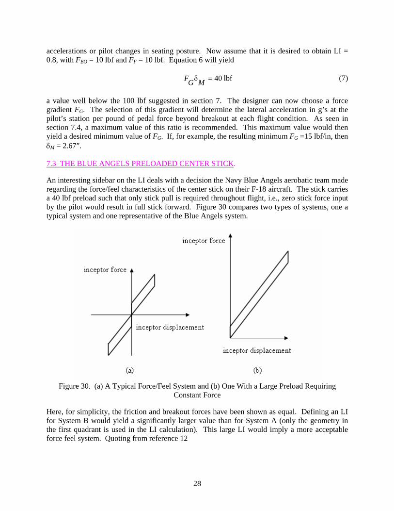
An interesting sidebar on the LI deals with a decision the Navy Blue Angels aerobatic team made regarding the force/feel characteristics of the center stick on their F-18 aircraft. The stick carries a 40 lbf preload such that only stick pull is required throughout flight, i.e., zero stick force input by the pilot would result in full stick forward. Figure 30 compares two types of systems, one a typical system and one representative of the Blue Angels system.
Figure 30. (a) A Typical Force/Feel System and (b) One With a Large Preload Requiring
Constant Force
Here, for simplicity, the friction and breakout forces have been shown as equal. Defining an LI for System B would yield a significantly larger value than for System A (only the geometry in the first quadrant is used in the LI calculation). This large LI would imply a more acceptable force feel system. Quoting from reference 12
28

“There’s a dead spot at the stick’s center [position], so we’d have to constantly push-pull, push-pull [through it] to keep our position…That could [induce] a PIO [pilot-induced oscillation]. We attach that 40-lb spring and rest our arm on our [right] leg, which acts as a fulcrum to help us [overcome] the spring.” ---Lt. Cdr. John D. Saccomando Blue Angel team member
The preload effectively creates a more linear force/feel system and apparently reduces the probability of a PIO. 7.4 THE VIRTUAL BOBWEIGHT AND PEDAL FORCE PER UNIT OF YAW ACCELERATION.
Bobweights have long been used to alter the effective longitudinal response characteristics of aircraft to column or longitudinal control inceptor inputs [7 and 13]. The first effect of such devices is an increase in the stick force per g. In this light, bobweights act as a safety feature, providing proprioceptive feedback information to the pilot with regard to normal accelerations caused by control inputs. In addition, they provide a constant stick force per g across the flight envelope. The dynamic effect of bobweights is more complicated because it alters system
transfer functions such as )(δ
sn
F
zcg , where is the normal acceleration at the aircraft center of
gravity and δF is the longitudinal force applied to the control inceptor (column or stick). It is interesting at this juncture to consider a brief survey of the effect of a bobweight on rudder control. Consider figure 31, which is a schematic representation of a rudder bobweight. Note that the positive yaw acceleration shown will create an inertial moment about the pedal axis in the direction shown. Effectively, this would mean that the pilot would have to apply a larger force to the right pedal to maintain current rudder deflection. The inertial moment is an obvious function of the bobweight mass and distanced from both the rudder pedal axis and the aircraft
center gravity. Figure 32 shows the Bode plots of the transfer function
zcgn
)(δ
sr
PF
(yaw
acceleration to pedal force input) for the DC-8 aircraft used in this study. Rudder actuator dynamics and yaw damper are included. The gain KBW transforms the yaw acceleration into an inertial moment on the rudder pedals. Here, the gain values are simply chosen arbitrarily to demonstrate the effect of a virtual bobweight on this transfer function. The linear pedal force/feel dynamics of equation 3 and the rudder actuator dynamics are included, but no yaw damper has been implemented. The term virtual is used here to emphasize the fact that the bobweight effect could be created artificially in the pedal force/feel system. This is particularly true if a fly-by-wire rudder control system is being used. The effect of KBW is seen to reduce the
magnitude of the )(δ
sr
PF
transfer function over a broad frequency range from 0.1 to over 20
rad/sec. The 4.3 dB reduction is equivalent to a 64% increase in the pedal force per unit of yaw acceleration in the rudder pedals.
29
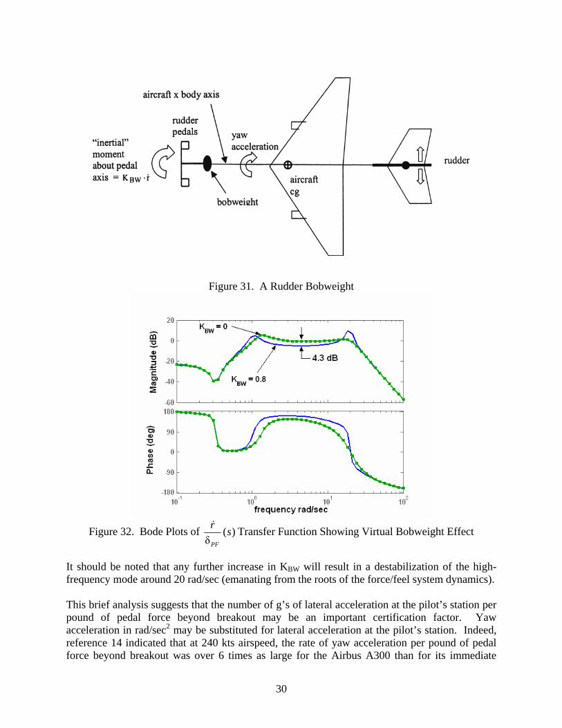
Figure 31. A Rudder Bobweight
Figure 32. Bode Plots of )(
δsr
PF
Transfer Function Showing Virtual Bobweight Effect
It should be noted that any further increase in KBW will result in a destabilization of the high-frequency mode around 20 rad/sec (emanating from the roots of the force/feel system dynamics). This brief analysis suggests that the number of g’s of lateral acceleration at the pilot’s station per pound of pedal force beyond breakout may be an important certification factor. Yaw acceleration in rad/sec2 may be substituted for lateral acceleration at the pilot’s station. Indeed, reference 14 indicated that at 240 kts airspeed, the rate of yaw acceleration per pound of pedal force beyond breakout was over 6 times as large for the Airbus A300 than for its immediate
30

predecessor, the Airbus A300-B2-B4. This fact, taken with the relatively small LI for the A300-600 (0.4) compared to the A300-B2-B4 (0.81), may have been a contributing factor in the American Airlines Flight 587 accident. An examination of figures 12, 14, and the force/displacement graph of figure 4 indicates the following: for the example DC-8 aircraft at the flight condition chosen, the number of g’s of lateral acceleration at the pilot’s station per pound of pedal force beyond breakout is approximately 0.022 for System A and 3.5.10-3 for System B. This yields a ratio of 6.3. Some limited data is available to shed some light on maximum values of the number of g’s of lateral acceleration per pound of pedal force. Reference 15 describes flight test results in which the Princeton Navion Variable Response Aircraft was configured to investigate wings-level turn modes. The data pertinent to this discussion are very limited. Figures 25 and 26 demonstrate a sharp degradation in handling qualities ratings when the lateral g’s per pound of pedal force increase beyond 0.005. In figure 33, favorable yaw coupling refers to the tendency of the nose of the aircraft to move in the direction of commanded turn, while in figure 34, favorable roll coupling refers to the tendency of the aircraft to roll in the direction of the commanded wings-level turn. The different symbols in figures 33 and 34 represent the Cooper-Harper ratings assigned by different pilots. Three facts must obviously be borne in mind in considering these results. First, the data is sparse. Second, the vehicle is not a transport aircraft. Third, the command/response characteristics for pedal inputs (wings-level turn) are not representative of those of a transport aircraft. Nonetheless, the sharp degradation in handling qualities that did occur for the lateral g’s per pound of pedal force beyond 0.005 suggests that this value may be worthy of further scrutiny as a limit for maximum pedal sensitivity.
31

Figure 33. Pedal Sensitivity Data From Reference 15 (High Favorable Yaw Coupling) (Different symbols indicate different evaluation pilots.)
32

Figure 34. Pedal Sensitivity Data From Reference 15 (Very High Favorable Roll Coupling) (Different symbols indicate different evaluation pilots.)
A brief review of some of the pilot comments associated with figures 33 and 34 are as follows: • Configuration: WLT5, Pilot: MP. Comments associated with square symbols in
figure 33:
at 0.008 sensitivity: “On-target time was approximately 50 percent, and of all the configurations tested, it was one of the worst for time on target…” at 0.0045 sensitivity: “Once stabilized, the aircraft was quite steady, and a good targeting solution was reached…No noticeable secondary motions were induced.”
• Configuration: WLT5, Pilot: BN. Comments associated with diamond symbols in
figure 33:
at 0.008 sensitivity: “There seemed to be a tendency to somehow overshoot the target…I got adequate performance but I was getting up to considerable
33
compensation – a little relaxed part of the time, working pretty hard the rest of the time.” at 0.0045 sensitivity: “What happened was that the lower sensitivity helped with the dithering problem of the sensitivity “overcontrol” problem I had on the previous run (pilot referring to run with 0.008 sensitivity) of getting on target due to dancing back and forth.”
• Configuration: WLT12, Pilot: MP. Comments associated with the square symbols in
figure 34:
at 0.0075 sensitivity: “The abruptness of the turn created by the rudder was such that time-on-target suffered dramatically. The pilot’s head tended to be thrown back and forth in the cockpit whenever the amount of rudder was changed.” at 0.005 sensitivity: “So, to get adequate performance requires an extensive amount of compensation to try to blend in very small and accurate amounts of rudder an to then hold that amount, if possible, with centerstick.”
• Configuration: WLT12, Pilot: KO. Comments associated with the circular symbols in
Fig. 34.
at 0.008 sensitivity: “Able to keep the pipper on the target 50 to 60 percent of the time. A lot of shaking around in the cockpit.” at 0.004 sensitivity: “The airplane was more comfortable to fly, as far as transverse g’s in the cockpit.”
• Configuration: WLT12, Pilot: RH. Comments associated with triangular symbols in
figure 34.
at 0.008 sensitivity: “It tends to be somewhat twitchy and sensitivity (sic)…” at 0.004 sensitivity: “Reducing the sensitivity to 400 (0.004) improved this configuration dramatically and made it quite easy to track the target.”
• Configuration: WLT12, Pilot: BN. Comments associated with diamond symbols in
figure 34.
at approx. 0.006 sensitivity: “It goes in the right direction, but it’s just a little bit too snappy. I tend to fight it a little with the stick, and I think I’m getting into a little PIO in roll.”
Equation 6 is now repeated for convenience.
34

)δ(
)22
1
2
MGBO
BO
FBO
FFFFF
LI+
⎥⎦
⎤⎢⎣
⎡+
−= (8)
In section 7, it was demonstrated that this relation could be used to determine an acceptable FGδM (maximum force), given a desired minimum value for LI and estimates of desired breakout and friction forces FBO and FF. Then a maximum pedal displacement δM could be chosen, finally yielding the pedal force gradient FG. With the results of the previous paragraph in mind, it is apparent, the choice of δM could be predicated on creating the value of FG that would provide a desired maximum value of g’s of lateral acceleration at the pilot’s station per pound of pedal force beyond breakout. 8. FORCE/FEEL SYSTEM COMPARISONS.
The question as to what might be the desirable characteristics of rudder pedal force/feel systems naturally arises at this juncture. One answer could come from examining and cataloging the pedal force/feel systems in aircraft that require precise yaw control as a typical part of their operational tasks. Military rotorcraft fall into this category. The handling qualities of modern military rotorcraft were ascertained through the completion of well-defined, low-speed flight tasks, in which specific performance requirements are called out [16]. For example, figure 35 is a page from reference 16 describing one such task, here the “hover task.” Note that precise heading control is required of the pilot/vehicle system.
Figure 35. A Rotorcraft Task Description From Reference 16
35
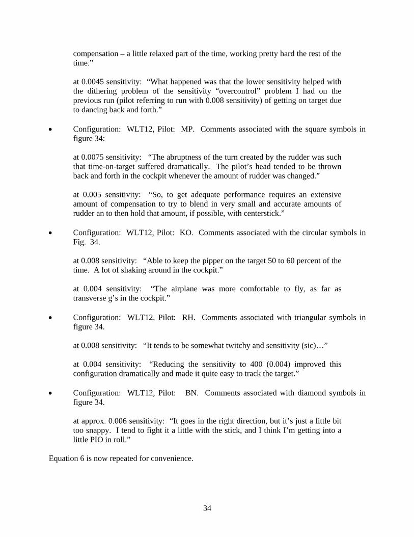
Four operational military rotorcraft were chosen for the study. These were the AH-64A Apache, the UH-60A Blackhawk, the CH-47D Chinook, and the CH-53E Sea Stallion. Originally, data for the RAH-66 Comanche was also sought. However, this vehicle does not possess pedal inceptors for yaw control. Rather, a twist grip is used on the cockpit sidestick controller for this purpose. Since an entirely different limb and muscle group is used with this inceptor, it was not considered appropriate to include its characteristics for comparison. These rotorcraft, as shown in figures 36-39, differ considerably in size, performance, and mission. In addition, and for the sake of comparison, three transport aircraft were included in the analysis, the Airbus A300-600 (at 240 kts), the Boeing 767, and the immediate predecessor to the Airbus A300-600, the Airbus A300-B2-B4. A particular airspeed was called out for the Airbus vehicles since the characteristics of their rudder force/feel system changes with airspeed. This is not true for the B-767 or any of the rotorcraft examined in this study. The A300-600 and B-767 transports are shown in figures 40 and 41. The A300-B2-B4 is very similar in configuration to that of the A300-600.
Figure 36. The AH-64A Apache Rotorcraft
36
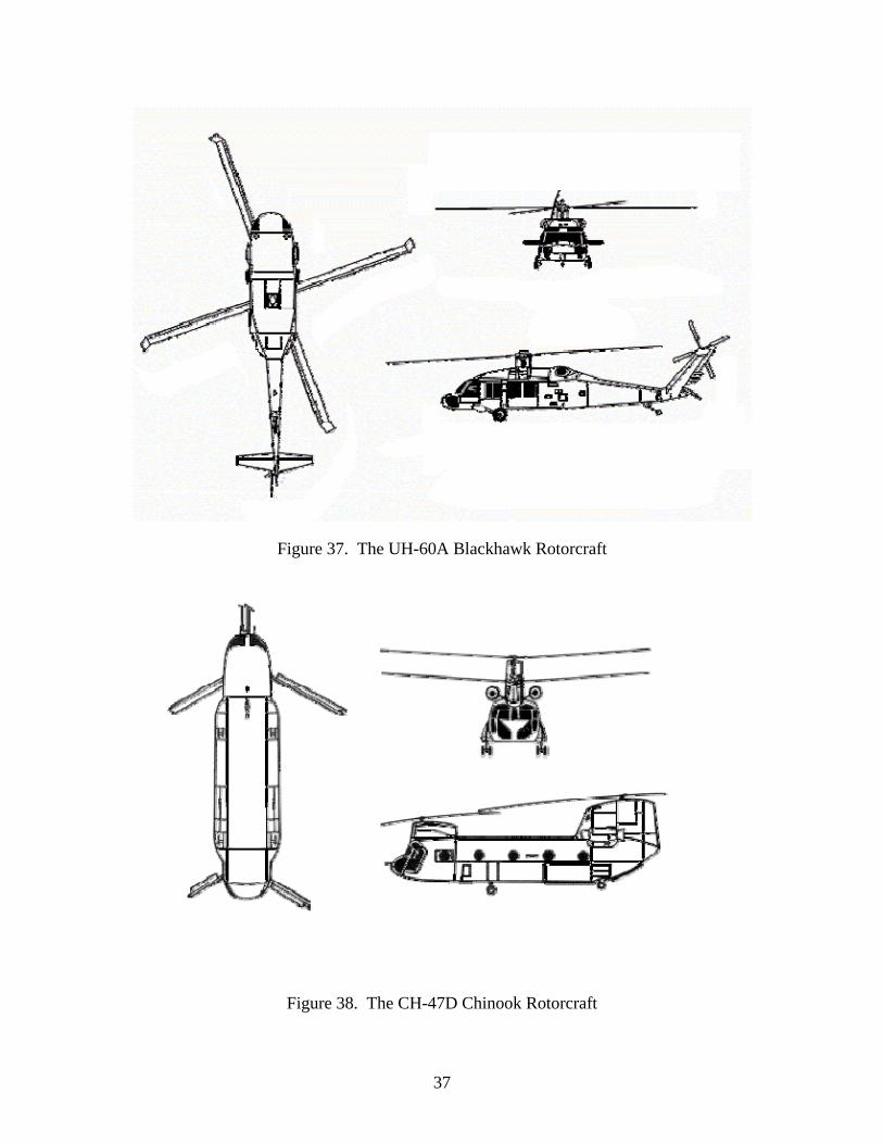
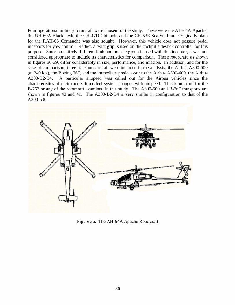
Figure 37. The UH-60A Blackhawk Rotorcraft
Figure 38. The CH-47D Chinook Rotorcraft
37
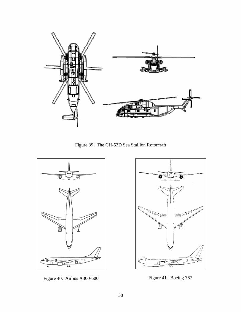
Figure 39. The CH-53D Sea Stallion Rotorcraft
Figure 41. Boeing 767 Figure 40. Airbus A300-600
38
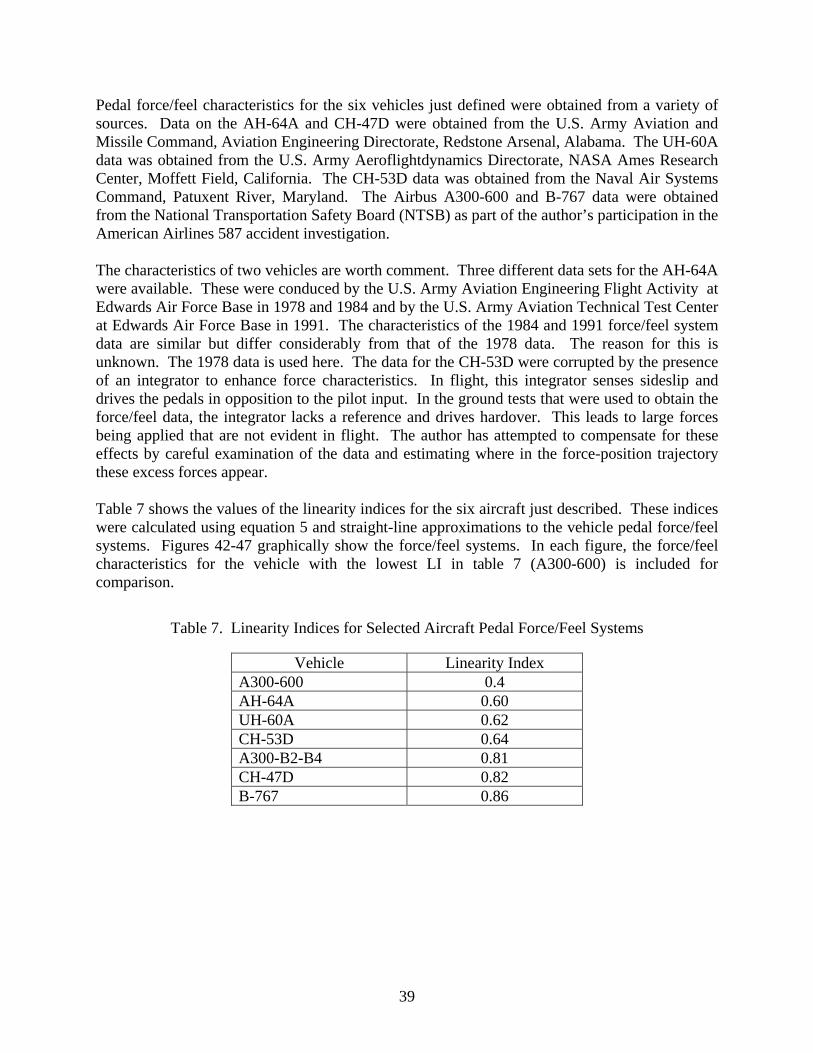
Pedal force/feel characteristics for the six vehicles just defined were obtained from a variety of sources. Data on the AH-64A and CH-47D were obtained from the U.S. Army Aviation and Missile Command, Aviation Engineering Directorate, Redstone Arsenal, Alabama. The UH-60A data was obtained from the U.S. Army Aeroflightdynamics Directorate, NASA Ames Research Center, Moffett Field, California. The CH-53D data was obtained from the Naval Air Systems Command, Patuxent River, Maryland. The Airbus A300-600 and B-767 data were obtained from the National Transportation Safety Board (NTSB) as part of the author’s participation in the American Airlines 587 accident investigation. The characteristics of two vehicles are worth comment. Three different data sets for the AH-64A were available. These were conduced by the U.S. Army Aviation Engineering Flight Activity at Edwards Air Force Base in 1978 and 1984 and by the U.S. Army Aviation Technical Test Center at Edwards Air Force Base in 1991. The characteristics of the 1984 and 1991 force/feel system data are similar but differ considerably from that of the 1978 data. The reason for this is unknown. The 1978 data is used here. The data for the CH-53D were corrupted by the presence of an integrator to enhance force characteristics. In flight, this integrator senses sideslip and drives the pedals in opposition to the pilot input. In the ground tests that were used to obtain the force/feel data, the integrator lacks a reference and drives hardover. This leads to large forces being applied that are not evident in flight. The author has attempted to compensate for these effects by careful examination of the data and estimating where in the force-position trajectory these excess forces appear. Table 7 shows the values of the linearity indices for the six aircraft just described. These indices were calculated using equation 5 and straight-line approximations to the vehicle pedal force/feel systems. Figures 42-47 graphically show the force/feel systems. In each figure, the force/feel characteristics for the vehicle with the lowest LI in table 7 (A300-600) is included for comparison.
Table 7. Linearity Indices for Selected Aircraft Pedal Force/Feel Systems
Vehicle Linearity Index A300-600 0.4 AH-64A 0.60 UH-60A 0.62 CH-53D 0.64 A300-B2-B4 0.81 CH-47D 0.82 B-767 0.86
39
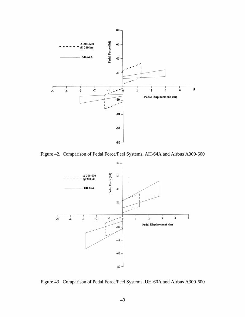
Figure 42. Comparison of Pedal Force/Feel Systems, AH-64A and Airbus A300-600
Figure 43. Comparison of Pedal Force/Feel Systems, UH-60A and Airbus A300-600
40
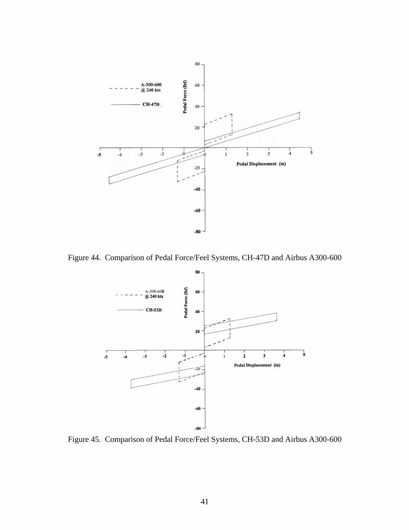
Figure 44. Comparison of Pedal Force/Feel Systems, CH-47D and Airbus A300-600
Figure 45. Comparison of Pedal Force/Feel Systems, CH-53D and Airbus A300-600
41
Figure 46. Comparison of Pedal Force/Feel Systems, B-767 and Airbus A300-600
Figure 47. Comparison of Pedal Force/Feel Systems, Airbus A300-B2-B4 and A300-600
42

9. DYNAMIC FORCE/FEEL SYSTEM CONSIDERATIONS.
Figures 6 and 7 clearly show that the static force/feel system characteristics are altered when dynamic effects are considered. This is due to the finite bandwidth of the force/feel dynamics. In addition, the linear and nonlinear effects of surface actuators affect the relationship between applied force and control surface movement. These characteristics should be included in any evaluation of rudder control system evaluations. Figure 48 demonstrates these characteristics with force/feel System B for the vehicle analyzed here (see figure 4). In this figure, a sinusoidal pedal force is being applied at the frequency of the aircraft’s Dutch roll mode and with an amplitude approximately creating the maximum pedal displacement. The resulting rudder movement is shown in the figure. The rudder actuator rate limit was reduced by 50% to demonstrate the effect. Note that the LI would decrease when the effects of force/feel and actuator dynamics are included. It is suggested that the LI be calculated using the variables shown in figure 48, i.e., rudder displacement and pedal force, and with a pedal input representing maximum displacements using a sinusoidal force at a frequency approximating the dutch roll mode frequency at a variety of flight conditions.
Figure 48. Effect of Force/Feel System Dynamics and Rudder Actuator Characteristics on Pedal
Force vs Rudder Position for Force/Feel System B
10. RUDDER (YAW) CONTROL REQUIREMENTS IN MILITARY HANDLING QUALITIES SPECIFICATIONS AND STANDARDS.
10.1 INTRODUCTION.
This section is a compilation of the requirements for aircraft rudder (yaw) control that have appeared in military handling qualities specifications and standards from 1959 to 1997. The compilation represents the distillation of approximately 3400 pages of requirements and background information. Attention is focused upon those requirements that would be appropriate for transport category aircraft. In terms of MIL-F-8785, this refers to aircraft
43
identified as Class II, while for later documents, it refers to aircraft identified as Class III. A comparison of these requirements with appropriate sections from 14 CFR Part 25, as summarized in section 2, can suggest areas in which the latter regulations may be augmented to enhance the safety of transport aircraft with regard to rudder control systems. 10.2 DOCUMENT REVIEW.
10.2.1 MIL-F-8785 (ASG) Military Specification, Flying Qualities of Piloted Airplanes.
Airspeed definitions used in MIL-F-8785: • VH maximum speed in level flight with maximum continuous power • VM maximum operational speed • VNRP speed for normal rated power • VR/C speed for maximum rate of climb •
CRSV stall speed in cruise configuration
• GSV stall speed in glide configuration
• LSV stall speed in landing configuration
• PASV stall speed in power approach configuration
• TOSV stall speed in takeoff configuration Note: Page numbers refer to MIL-F-8785 as reproduced in the User Guide for MIL-F-8785B [17]; paragraph numbers refer to MIL-F-8785, itself. p. 585, Paragraph 1.3 Classification:
“For purposes of this specification, airplanes shall be divided into the following classes:
Class I Primary trainer, observation, and other light airplanes specifically
designated by the procuring activity. Class II Horizontal bomber, cargo, transport, glider, patrol, antisubmarine,
early warning, minelayer, heavy attach, and trainers for class II airplanes.
Class III Fighter, interceptor, general purpose attack, and trainers for class III airplanes.”
p. 588, Paragraph 3.2.1 Control friction and breakout force:
“Longitudinal, lateral, and directional controls shall exhibit positive centering in flight at any normal trim setting. Although absolute centering is not required, the degree of centering shall be such that the combined effects of centering, breakout force, stability and force gradient do not produce objectionable flight characteristics, or permit large departures from trim conditions with controls free.
44

Breakout forces, including friction, reel preload, etc, shall be within the limits given (below). These values refer to the pilot control force required to start movement of the control surface, and apply in flight at all attainable conditions of trimmed airspeed, altitude, temperature, and control deflection.
Allowable breakout forces (including friction), pounds
Rudder Class II-C (carrier-based) min = 1 lb, max = 7 lb
Class II-L (land-based) min = 1 lb, max = 14 lb”
p. 589, Paragraph 3.2.3 Rate of control displacement:
“The ability of the airplane to perform the maneuvers expected of it shall not be limited by the rate of control surface deflection or auxiliary control operation, nor shall the rates of operation of either primary controls or auxiliary devices result in objectionable flight characteristics.”
p. 597, Paragraph 3.4.4 Static directional stability (rudder position):
“The airplane shall possess rudder-fixed directional stability such that, in the sideslips specified…right rudder pedal deflection from the wings-level position is required in left sideslips and left rudder pedal deflection is required in right sideslips. For angles of sideslip between +/- 15 degrees from the wings-level condition, the variation of sideslip angle with rudder pedal deflection shall be essentially linear. Throughout the remainder of the range of required pedal deflections, an increase in pedal deflection shall always be required for an increase in sideslip.”
p. 598, Paragraph 3.4.5 Static directional stability (rudder force):
“The airplane shall possess rudder-free stability such that, in the sideslips specified…right rudder force is required in left sideslip and left rudder force is required in right sideslip. For angle of sideslip between +/-15 degrees from the wings-level, straight-flight condition, the variation of sideslip angle with rudder force shall be essentially linear. At greater angles of sideslip, a lightening of the rudder force is acceptable, but the rudder force shall never reduce to zero or overbalance.”
p. 599, Paragraph 3.4.11 Directional control (symmetric power):
“For all airplanes, directional control shall be sufficiently effective to maintain wings-level straight flight in the configurations and speed ranges specified…with rudder control forces not greater than 180 lb when the airplane is trimmed
45

directionally at the trim speeds specified (below). Additional requirements for directional control in dives are specified in paragraph 3.4.15.
Configuration Speed Range Cruise 1.4 to VNRP
GSVPower on; clean 0.75 VNRP to VH
Power on; clean (climb) 0.85 VR/C or 1.15
(whichever is greater) to 1.3 VR/C
GSV
Combat VNRP to VM
Glide to VH
GSV Dive All speed normally attained in
dive configuration Landing to limit structural speed in landing
configuration LSV
Power approach to limit structural speed in power
approach configuration” LSV
p. 599, Paragraph 3.4.12 Directional control (asymmetric power):
“On all multiengine airplanes in takeoff configuration with the most critical outboard engine inoperative…it shall be possible, at the lightest normal takeoff loading and with takeoff power on the remaining engine or engines, to achieve and maintain straight flight with a bank angle not greater than 5 degrees, at all speed above 1.2 ….With trim settings normally employed in a symmetric power takeoff, the rudder pedal force required to maintain straight flight with asymmetric power, as defined above, shall not exceed 180 lb.”
TOSV
p. 599, Paragraph 3.4.13 Directional control during takeoff and landing:
“The rudder control, in conjunction with other normal means of control, shall be adequate to maintain straight paths on the ground during normal takeoffs and landings. For classes II and III airplanes, the requirement shall apply to calm air, and in 90-degree cross winds of at least 30 percent or 40 knots, whichever is less…This requirement shall be met with not more than 180 lb pedal force.”
LSV
46

p. 599, Paragraph 3.4.13.1 Directional control during takeoff and landing:
“Without the use of wheel brakes, classes II-C… airplanes shall be capable of maintaining a straight path on the ground, at airspeeds of 30 knots and above, during takeoffs and landings in 90 degree cross wind of at least 10 percent
without exceeding 180 lb pedal force.” LSV
p. 600, Paragraph 3.4.14 Directional control to counteract adverse yaw:
“In the rolling maneuvers described in paragraph 3.4.9 (roll out of a trimmed, level steady 45 degree banked turn at 1.4 in cruise configuration, and at
1.4 in power approach configuration, shall not exceed 15 degrees. The roll shall continue until a bank angle of 45 degrees is reached in the opposite direction) but with the rudder employed for coordination rather than held fixed, directional control effectiveness shall be adequate to maintain zero sideslip, with rudder forces no greater than 180 lb.”
CRSV
PASV
p. 600, Paragraph 3.4.15 Directional control in dives:
“When trimmed directionally at the service ceiling in the power on configuration, the rudder control shall be capable of maintaining zero sideslip throughout the dives and pullouts of paragraph 3.3.16 (with the airplane trimmed for level flight at VM, the elevator control forces required in dives to any attainable speed within the operational flight envelope shall not exceed …75 lb push and 15 lb pull in class II airplanes. In similar dives, but with trim optional following the dive entry, it shall be possible with normal piloting technique to maintain the forces within the limits of…20 lb push or pull in class II airplanes) without exceeding…180 lb rudder pedal force for class II airplanes.”
p. 610, Paragraph 6.5 Control force coordination:
“The control forces required to perform maneuvers which are normal for the airplane should have magnitudes which are related to the pilot’s capability to produced such forces. As a tentative guide on this subject, it is desired that the relative magnitudes of control forces in coordinated maneuvers should be approximately in the ratio of 50, 175, and 25 pound (or. 2:7:1) for elevator, rudder, and aileron force, respectively for a stick-control airplane. For a wheel control airplane, the elevator and aileron control forces may be increased by 50 percent. These ratios refer to the peak forces obtained when, starting from level flight in power on configuration at medium altitude, a rolling pullout maneuver is performed in which approximately 2/3 of the available rolling velocity is obtained simultaneously with a normal load factor of approximately 1+2/3(nL-1), maintaining zero sideslip with the rudder.12”
12 nL refers to the limit load factor for a given loading based on structural considerations.
47
p. 611, Paragraph 6.11 Control system characteristics:
“…Some of the known important variables, even in a simple system, are friction in the control valve, friction, flexibility, back-lash, gear ratio, and inertia in the control system, viscous damping and preload in the control system or valve; rate limiting of the control actuator; and the level of aircraft static and dynamic stability. The introduction of nonlinear linkages or valve characteristics further multiplies the important variables. In general, the designer should make every effort to provide a linear or smoothly varying response to cockpit control deflection and to control force for all amplitudes of control input, including values of stick force with the range of allowable breakout forces…and small control deflections such as those required in tracking. The phase lag between cockpit control deflection or force and control surface deflection should be kept to a minimum for reasonably large amplitude motions at frequencies considerably above the airplane natural frequencies, and should not increase unduly at very small amplitudes.”
10.2.2 Background Information and User Guide for MIL-F-8785B (ASG), Military Specification—Flying Qualities of Piloted Airplanes.
Note: Page numbers refer to the User Guide [17]; paragraph numbers refer to MIL-F-8785B, itself. p. 10, Paragraph 1.3 Classification of airplanes:13
For the purposes of this specification, an airplane shall be placed in one of the following Classes: Class I Small, light airplanes such as Light utility Primary trainer Light observation Class II Medium weight, low-to-medium maneuverability airplanes such as Heavy utility/search and rescue Light or medium transport/cargo/tanker
Early warning/electronic countermeasures/airborne command,
Control, or communications relay Antisubmarine Assault transport Tactical bomber Heavy attack Trainer for Class II Class III Large, heavy, low-to-medium maneuverability airplanes such as
13 Note that a large transport aircraft would now be in Class III, whereas in MIL-F-8785, it would be in Class II.
48

Heavy transport/cargo/tanker Heavy bomber
Patrol/early warning/electronics countermeasures/airborne command, control, or communications relay
Trainer for Class III Class IV High-maneuverability airplanes such as
Fighter/interceptor Attack Tactical reconnaissance Observation Trainer for Class IV p. 14, Paragraph 1.4 Flight Phase Categories: Nonterminal Flight Phases:
Category A Those nonterminal Flight Phases that require rapid maneuvering, precision tracking or precise flight-path control. Included in this Category are: a. Air-to-air combat f. In-flight refueling
(receiver) b. Ground attack g. Terrain following c. Weapon delivery/launch h. Antisubmarine search d. Aerial recovery i. Close formation flying e. Reconnaissance
Category B Those nonterminal Flight Phases that are normally accomplished using gradual maneuvers and without precision tracking, although accurate flight-path control may be required. Included in this category are: a. Climb e. Descent b. Cruise f. Emergency descent c. Loiter g. Emergency deceleration d. In-flight refueling h. Aerial delivery
(tanker)
Terminal Flight Phases:
Category C Terminal Flight Phases are normally accomplished using gradual maneuvers and usually require accurate flight-path control. Included in this Category are: a. Takeoff d.Wave-off/go-around b. Catapult takeoff e. Landing c. Approach
49

p. 236, Paragraph 3.3.2.2 Roll rate oscillations:
“….it is necessary to cross control to effect coordination, that is, left rudder pedal with right aileron. Since pilots do not normally cross control (and, if they must, have great difficulty in doing so)…”
p. 272, Paragraph 3.3.2.4 Sideslip excursions:
“…on the other hand, the yawing moment is in the proverse sense or is caused by roll rate, coordination is far more difficult. For perverse yaw-due-to-aileron, the pilot must cross control, and for either adverse or proverse yaw-due-to roll rate, required rudder inputs must be proportional to roll rate. Pilots find these techniques unnatural and difficult to perform.”
Since pilots do not normally cross control and, if they must, have great difficulty “in doing so, for –360 deg <= ψβ <= -90 deg, oscillations in sideslip either to go unchecked or are amplified by the pilot’s efforts to coordinate with rudder pedals.” Note: ψβ is the phase angle is a cosine representation of the Dutch roll component of sideslip – negative for a lag:
reesdeg360)1n(t360n
d−+
τ−
=ψ ββ
where is the time for the dutch roll component of the sideslip response to
reach the nth local maximum for a right step or pulse aileron control command, or the nth local minimum for a left command. For pulse inputs, time is measured from a point halfway through the duration of the pulse.
βnt
τd is the damped period of the Dutch roll defined as 2ddn
d1
2
ζ−ω
π=τ
In certain cases, Reference A114 allows use of rudder pedals to meet the roll performance requirement.” Quoting from Ref. A1: “…rudder pedals may be used to reduce sideslip that retards roll rate (not to produce sideslip that augments roll rate) if rudder pedal inputs are simple, easily coordinated with aileron-control inputs, and consistent with piloting techniques for the airplane Class and mission. For Class III aircraft: For Flight Phase Category shown and for Level 1 HQs
A φt = 30 deg in 1.5 sec B φt = 30 deg in 2.0 sec C φt = 30 deg in 2.5 sec
Where φt is bank angle change in time t.
14 Reference A1 is MIL-F-8785B (ASG), 1969.
50
From these observations, it can be seen that even if lateral acceleration is an important independent flying qualities parameter, not enough research has been performed to formulate a requirement on lateral acceleration at this time.”
p. 289, Paragraph 3.3.2.5 Control of Sideslip in rolls:
“In the rolling maneuvers described in 3.3.4, but with the rudder pedals used for coordination for all Classes, directional control effectiveness shall be adequate to maintain zero sideslip with a rudder pedal force not greater than…100 pounds for all other combinations of Class, Flight Phase Category and Level.”
p. 290, Paragraph 3.3.2.6 Turn coordination:
“It shall be possible to maintain steady coordinated turns in either directions, using…30 deg of bank for Class III airplanes, with a rudder pedal force not exceeding 40 pounds. It shall be possible to perform steady turns at the same bank angle with rudder pedals free, with an aileron stick force not exceeding 5 pounds or an aileron wheel force not exceeding 10 pounds.”
p. 291, Paragraph 3.3.3 Lateral-Directional Pilot-Induced Oscillations:
“There shall be no tendency for sustained or uncontrollable lateral directional oscillations resulting from efforts of the pilot to control the airplane.”
p. 344, Paragraph 3.3.4.5 Rudder-pedal-induced rolls:
“For Levels 1 and 2, it shall be possible to raise a wing by use of rudder pedal alone, with right rudder pedal force required for right rolls and left rudder pedal force required for left rolls. For Level 1, with the aileron control free, it shall be possible to produce a roll rate of 3 deg/sec with an incremental rudder pedal force of 50 pounds or less. The specified roll rate shall be attainable from coordinated turns at up to +/- 30 deg bank angle…”
p. 345, Paragraph 3.3.5 Directional control characteristics:
“Directional stability and control characteristics shall enable the pilot to balance yawing moments and control yaw and sideslip. Sensitivity to rudder pedal forces shall be sufficiently high that directional control and force requirements can be met and satisfactory coordination can be achieved without unduly high rudder pedal forces, yet sufficiently low that occasional improperly coordinated control inputs will not seriously degrade the flying qualities.”
51

p. 346, Paragraph 3.3.5.1 Directional control with speed change: “When initially trimmed directionally with symmetric power, the trim change…with speed shall be such that straight flight can be maintained over a speed range of +/- 30 percent of the trim speed or +/- 100 knots equivalent airspeed, whichever is less (except where limited by boundaries of the Service Flight Envelope)…rudder pedal forces shall not exceed 40 pounds at the specified conditions for Levels 1 and 2 nor 180 pounds for Level 3.”
p. 346, Paragraph 3.3.5.1.1 Directional control with asymmetric loading:
“When initially trimmed directionally with each asymmetric loading specified in the contract at any speed in the Operational Flight Envelope, it shall be possible to maintain a straight flight path throughout the Operational Flight Envelope with rudder pedal forces not greater than 100 pounds for Levels 1 and 2 and not greater that 180 pounds for Level 3, without retrimming.”
p. 348, Paragraph 3.3.6 Lateral-directional characteristics in steady sideslips:
“The requirements (below) are expressed in terms of characteristics in rudder-pedal-induced steady, zero-yaw-rate sideslips with the airplane trimmed for wings-level straight flight. …(The paragraph below) applies at sideslip angles up to those produced or limited by:
a. Full rudder pedal deflection b. 250 pounds of rudder pedal force, or c. Maximum aileron control or surface deflection”
p. 350, Paragraph 3.3.6.1 Yawing moments in steady sideslips:
“For the sideslips (created as just described) right rudder deflection and force shall produce left sideslips and left rudder pedal deflection and force shall produce right sideslips. For Levels 1 and 2 the following requirements shall apply. The variation of sideslip angel with rudder pedal deflection shall be essentially linear for sideslip angles between +15 degrees and –15 degrees. For large sideslip angles, an increase in rudder pedal deflection shall always be required for an increase in sideslip. The variation of sideslip angle with rudder pedal force shall be essentially linear for sideslip angles between +10 degrees and -10 degrees. Although a lightening of rudder pedal force is acceptable for sideslip angles outside this range, the rudder pedal force shall never reduce to zero.”
p. 356, Paragraph 3.3.7 Lateral-directional control in cross winds:
“It shall be possible to take off and land with normal pilot skill and technique in 90 degree cross winds, from either side, of velocities up to those specified
52
(below)…rudder pedal forces shall not exceed 100 pounds for Level 1 nor 180 pounds for Levels 2 and 3.”
Level 1 and 2; Class III; Cross Wind = 30 knots
p. 358, Paragraph 3.3.7.1 Final approach in cross winds:
“…rudder and aileron-control power shall be adequate to develop at least 10 degrees of sideslip in the power approach with rudder pedal forces not exceeding the values in (the paragraph above).”
p. 364, Paragraph 3.3.9 Lateral-directional control with asymmetric thrust:
“Following sudden asymmetric loss of thrust from any factor, the airplane shall be controllable.”
p. 365, Paragraph 3.3.9.1 Thrust loss during takeoff run:
“It shall be possible for the pilot to maintain control of an airplane on the takeoff surface following sudden loss of thrust from the most critical factor. Thereafter, it shall be possible to achieve and maintain a straight path on the takeoff surface without a deviation of more than 30 feet from the path originally intended, with rudder pedal forces not exceeding 180 pounds.”
p. 366, Paragraph 3.3.9.2 Thrust loss after takeoff:
“The rudder pedal force required to maintain straight flight with asymmetric thrust shall not exceed 180 pounds.”
p. 387, Paragraph 3.5.2.1 Control centering and breakout forces:
“Longitudinal, lateral, and lateral controls should exhibit positive centering in flight an any normal trim setting. Although absolute centering is not required, the combined effects of centering, breakout force, stability, and force gradient shall not produce objectionable flight characteristics, such as poor precision tracking ability, or permit large departures from trim conditions with controls free. Breakout forces, including friction, preload, etc, shall be within the limits (below). The values below are for Levels 1 and 2; the upper limits are doubled for Level 3. Rudder; Class III, min = 1 lb; max = 14 lb Although there are many indications that breakout forces should be a function of control force sensitivity (angular acceleration per pound of force) or some other force gradient, this approach was not used. The main reason for this is that there is not enough data (relating breakout forces and sensitivity) to justify the
53

additional complication, especially when measurement of breakout forces is usually quite imprecise anyway.”
p. 390, Paragraph 3.5.2.3 Rate of control displacement:
“The ability of the airplane to perform the operational maneuvers required of it shall not be limited in the atmospheric disturbances specified in 3.7 by control surface deflection rates.”
p. 392, Paragraph 3.5.3 Dynamic characteristics:
“The response of the control surfaces in flight shall not lag the cockpit control force inputs by more than the angles shown (below), for frequencies equal to or less than the frequencies shown (below).
Levels 1 and 2 Categories A and C Flight Phases: 30 deg Category B Flight Phases: 45 deg Level 3 All Flight Phases: 60 deg
For rudder and aileron the upper frequency is dnω or )/1( Rτ (which ever is larger). The lags referred to are the phase angles obtained from steady-state frequency responses, for reasonably large-amplitude force inputs. The lags for very small control-force amplitudes shall be small enough that the do not interfere with the pilot’s ability to perform any precision tasks required in normal operation.”
p. 397, Paragraph 3.5.3.1 Control feel:
“In flight, the cockpit-control deflection shall not lead the cockpit-control force for any frequency or force amplitude. This requirement applies to the elevator, aileron, and rudder controls. In flight, the cockpit-control deflection shall not lag the cockpit-control force by more than the angles listed (above) for frequencies equal to or less than those listed (above), for reasonably large force inputs. The lags for very small control-force amplitudes shall not interfere with the pilot’s ability to perform precision tasks required in normal operation.”
(The requirement beginning with ‘In flight…’) “was done because lags in the feel system can cause control problems.”
p. 398, Paragraph 3.5.3.2 Damping:
“All control system oscillations shall be well damped, unless they are of such an amplitude, frequency, and phasing that the do not results in objectionable oscillations of the cockpit controls or the airframe during abrupt maneuvers and
54
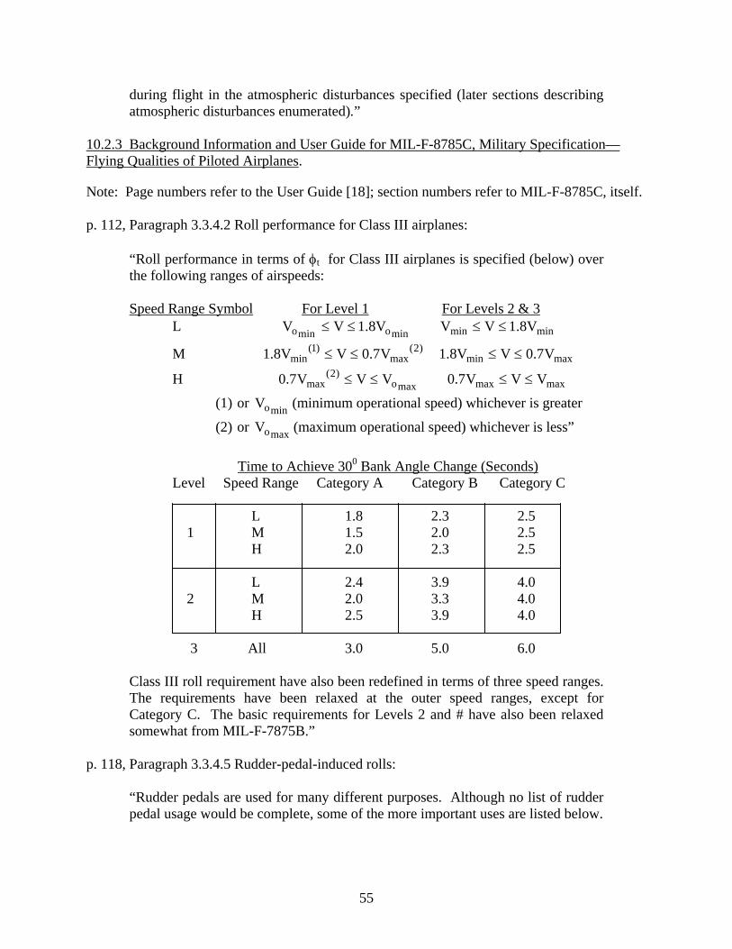
during flight in the atmospheric disturbances specified (later sections describing atmospheric disturbances enumerated).”
10.2.3 Background Information and User Guide for MIL-F-8785C, Military Specification—Flying Qualities of Piloted Airplanes.
Note: Page numbers refer to the User Guide [18]; section numbers refer to MIL-F-8785C, itself. p. 112, Paragraph 3.3.4.2 Roll performance for Class III airplanes:
“Roll performance in terms of φt for Class III airplanes is specified (below) over the following ranges of airspeeds: Speed Range Symbol For Level 1 For Levels 2 & 3 L V minomino V8.1V ≤≤ minmin V8.1VV ≤≤
M )2(max
)1(min V7.0VV8.1 ≤≤ maxmin V7.0VV8.1 ≤≤
H maxo)2(
max VVV7.0 ≤≤ maxmax VVV7.0 ≤≤
(1) or minoV (minimum operational speed) whichever is greater
(2) or maxoV (maximum operational speed) whichever is less”
Time to Achieve 300 Bank Angle Change (Seconds) Level Speed Range Category A Category B Category C
L 1.8 2.3 2.5 1 M 1.5 2.0 2.5 H 2.0 2.3 2.5 L 2.4 3.9 4.0 2 M 2.0 3.3 4.0 H 2.5 3.9 4.0 3 All 3.0 5.0 6.0
Class III roll requirement have also been redefined in terms of three speed ranges. The requirements have been relaxed at the outer speed ranges, except for Category C. The basic requirements for Levels 2 and # have also been relaxed somewhat from MIL-F-7875B.”
p. 118, Paragraph 3.3.4.5 Rudder-pedal-induced rolls:
“Rudder pedals are used for many different purposes. Although no list of rudder pedal usage would be complete, some of the more important uses are listed below.
55
a. To perform a crosswind landing-either employ a steady-rudder-pedal-induced sideslip or else a decrab maneuver.
b. To augment roll rate anywhere within the flight envelope. c. To raise a wing when the pilot is busy with his hands, such as when taking
a clearance. d. For tracking, for example, in air-to-ground gunnery in a crosswind or
when acquiring targets. e. For wing-overs or other tactical maneuvers to obtain a rapid change in
heading or bank angle. f. For close formation flying. g. To lose altitude as in a “forward” sideslip or to improve visibility, for
example, a pilot landing from the rear seat of a tandem-seat airplane. h. To counter yawing moments from propeller torque, speed or Mach
number change, asymmetric thrust or stores, etc. i. To coordinate turn entries or steady turns. j. To taxi.
The requirement in MIL-F-8785B directly addressed many of the above topics. ASD reports feedback ranging from ‘three degrees per second is not enough’ to ‘roll due to rudder is not required’, indicating that some other factors need to be taken into account…although item c above is particularly valid for single-seat airplanes it is not necessary for (multi-crew transports). The preceding discussion raises some obvious questions: is rudder-pedal-induced roll a valid requirement? Is 3 deg/sec enough or too much? Should a maximum value be specified? Are the requirements a function of airplane Class or task? Lacking answers to these questions the decision was made to delete the requirement completely. We can probably be certain that ‘negative’ roll due to rudder is undesirable, but the designer is encouraged to take task and configuration variables into account in establishing and meeting requirements in this area.”
p. 121, Paragraph 3.3.9 Lateral-directional control with asymmetric thrust:
“Following sudden asymmetric loss of thrust from any factor, the airplay shall be safely controllable in the crosswind (below) from the unfavorable direction…‘Safely controllable’ means, in addition to having sufficient control effectiveness, that it must not be necessary to sacrifice a required performance capability, such as a climb gradient with one or two engines out, in order to achieve controllability,
Crosswind velocity (Class III) Levels 1 and 2: 30 knots Level 3 15 knots”
56

p. 137, Paragraph 3.4.4.1 Control force coordination:15
“The cockpit control forces required to perform maneuvers which are normal for the airplane should have magnitudes which are related to the pilot’s capability to produce such forces in combination. The following control force levels are considered to by limiting values compatible with the pilots capability to apply simultaneous forces: Type Control Pitch Roll Yaw Wheel 75 pounds 40 pounds Pedal 175 pounds”
p. 147, Paragraph 3.5.3 Dynamic characteristics:
“A linear or smoothly varying airplane response to cockpit-control deflection and to control force deflection and to control force shall be provided for all amplitudes of control input. The response of the control surfaces in flight shall not lag the cockpit-control force inputs by more that the angles shown (below), for frequencies equal to or less than the frequencies shown (below).”
Note: The allowable lags for each Level are identical to that enumerated in the Background Information and User Guide for MIL-F-8785B(ASG). However, the ‘Upper Frequency’ in rad/sec for roll and yaw has been modified and now reads: “the largest of or dnω )/1( Rτ or 2 (which ever is larger).”
“In addition, the response of the airplane motion shall not exhibit a time delay longer than the following for a pilot-initiated step control force: Level 1: 0.1 sec Level 2: 0.2 sec Level 3: 0.25 sec (The allowable lags have) been retained in the form of a requirement on control surface motion, in contradiction with the emphasis on airplane response, elsewhere in MIL-F-8785C…The phase lag at any given frequency is the product of that frequency times the time delay. The time delay is to be measured from the pilot’s initiation of a step control input until the first indication of control surface motion (for allowable lags) or overall airplane response in the commanded motion variable (for allowable time delay) for that control input. Generally, one would use the pitch, roll, and yaw controls, respectively. …Reference 56d16 indicates that higher values (of time delay) may be acceptable for Class III but there is insufficient data to support requirements at this time.”
15 MIL-8785B did not include pedal forces in its requirements. 16 Reference 56d: Anon., “Flying Qualities Design Criteria,” Proceedings of AFFDL Flying Qualities Symposium
-80-3067, May 1980, pp. 253-276. Held at Wright-Patterson AFB in October 1979, AFWAL-TR
57

10.2.4 Proposed MIL Standard and Handbook—Flying Qualities of Air Vehicles, Vol. II: Proposed MIL Handbook.
Note: Page numbers refer to the document cited above [19]; section numbers refer to the proposed Standard, itself. It should be emphasized that new paragraph numbering was introduced in the document cited above. Because of this, and at the risk of restating requirements that have been treated in earlier documents, the following summary will catalog proposed MIL Standard requirements for yaw-axis controllers. Quoting from the reference cited above:
“The MIL Standard is a skeleton document consisting of incomplete requirements in verbal form which are to be completed by the procuring activity using numerical criteria from the MIL Handbook. A custom MIL Standard will be developed for each new aircraft procurement or major modification of an existing aircraft, as follows:
1. Identify mission requirements. 2. Break down requirements into piloting tasks. 3. For each paragraph in the MIL Standard, select the most appropriate
handling quality criterion from the MIL Handbook and insert into the Standard.”
p. 550, Paragraph 3.6.1.2.1 Bandwidth requirements for wings-level turn mode17:
a) Dynamic response to direct force control (DFC) input: “The bandwidth18 of the open-loop response of heading or lateral flight path angle to the DFC control input shall be greater than 1.25 rad/sec (for Level 1, Category A Flight Phases), 0.6 rad/sec (for Level 2, Category A Flight Phases), 0.3 rad/sec (for Level 1, Category C Flight Phases), and 0.12 ) for Level 2, Category C Flight Phases).”19 b) Steady-state response to direct force control input: Note: It was felt by the author that this requirement was inappropriate for Class III aircraft.
17 This requirement was drafted for aircraft with direct side-force control. However, it may shed light upon yaw- control requirements when the rudder is the side-force control effector. 18 Bandwidth here is defined in a particular manner as a handling qualities parameter. 19 Underline quantities here and in what follows represent recommended values. The actual document leaves these numerical requirements blank.
58

c) Direct force control forces and deflections:
“When the rudder pedals are to be used as the direct force controller, the requirements of 3.6.6 (see appropriate paragraph below) may be used as a guide.”
d) Pilot acceleration: “Abrupt, large DFC inputs shall not produce head or arm motions which interfere with task performance. Pilot restraints shall not obstruct his normal field of view nor interfere with manipulation of any cockpit control required for task performance.”
Note: No specific maximum accelerations were recommended here. However, the document referred to flight tests that suggested that values larger that 0.005 g’s/lb (lateral acceleration per pound of DFC force) were accompanied by degraded pilot opinion ratings. p. 604, Paragraph 3.6.2.2 Pilot-induced yaw oscillations:
“There shall be no tendency for sustained or uncontrollable yaw oscillations resulting from efforts of the pilot to control the aircraft.”
p. 606, Paragraph 3.6.2.3 Residual yaw oscillations:
“Any sustained residual oscillations in calm air shall not interfere with the pilot’s ability to perform the tasks required in service use of the aircraft.”
p. 607, Paragraph 3.6.3 Yaw axis control for takeoff and landing in crosswinds:
“It shall be possible to take off and land with normal pilot skill and technique in 90 deg crosswinds from either side of velocities up to 30 kt (Levels 1 and 2, Class 3) and 15 kt (Level 3, Class IIII).”
p. 631, Paragraph 3.6.6 Yaw axis control forces:
“Sensitivity to yaw control pedal forces shall sufficiently high that directional control and force requirements can be met and satisfactory coordination can be achieved without unduly high control forces, yet sufficiently low that occasional improperly coordinated control inputs will not cause a degradation in flying qualities levels.”
p. 633, Paragraph 3.6.6.1 Yaw axis control force linearity:
“The following requirements are expressed in terms of characteristics in yaw-control-induced steady, zero-yaw-rate sideslips with the airplane trimmed for wings-level straight flight, at sideslip angles up to those produced by:
59
a) Full yaw-control-pedal deflection, of b) 250 pounds of yaw-control-pedal force, or c) Maximum roll control or surface deflection
…Right yaw-control-pedal force shall produce left sideslips and left yaw-control-pedal force shall produce right sideslips. For Levels 1 and 2 the following requirements shall apply. The variation of sideslip angle with yaw-control-pedal force shall be essentially linear for side-slip angles between +10 degrees and –10 degrees.20 Although a lightening of pedal force is acceptable for sideslip angles outside this range, the pedal force shall never reduce to zero.”
p. 635, Paragraph 3.6.6.2.1 Yaw axis control force limits in rolling maneuvers: “In the maneuvers described in 3.5.9, (given above in describing document III, paragraph 3.3.4.2 for Class III airplanes) directional control effectiveness shall be adequate to maintain zero sideslip with pedal forces not greater than 100 lb (for Class III airplanes, all Flight Phase Categories, all HQ Levels).”
p. 637, Paragraph 3.6.6.2.2 Yaw axis control force limits in steady turns:
“It shall be possible to maintain steady coordinated turns in either direction, using (for Class III airplanes) 30 degrees of bank with a pedal force not exceeding 40 lb, with the airplane trimmed for wings-level straight flight. These requirements constitute Levels 1 and 2.”
p. 639, Paragraph 3.6.6.2.3 Yaw axis control force limits during speed changes:
“When initially trimmed directionally with symmetric power, the trim change with speed shall be that wings-level straight flight can be maintained over a speed range of +/- 30 percent of the trim speed or +/- 100 kt equivalent airspeed, whichever is less (except where limited by boundaries of the Service Flight Envelope) with yaw-control-pedal forces not greater than 40 lb (for Levels 1 and 2 and) 180 lb for (Level 3) without retrimming.”
p. 641, Paragraph 3.6.6.2.4 Yaw axis control force limits in crosswinds:
“It shall be possible to take off and land in the crosswinds specified in 3.6.3 (for Class II airplanes and Levels 1 and 2, 30 kt; for Level 3, 15 kt) without exceeding the following yaw control forces (100 lb for Level 1, 180 lb for Levels 2 and 3).”
p. 643, Paragraph 3.6.6.2.5 Yaw axis control force limits with asymmetric loading: “When initially trimmed directionally with each asymmetric loading specified in Paragraph 3.1.1 (the envelope of center of gravity and weight for each flight
20 The underline quantities here and in what follows are recommended values specified by the proposed MIL Standard. The actual document leaves these values blank.
60
phase shall be specified by the contractor. In addition, the contractor shall specify the maximum c.g. excursion attainable through failure in systems or components of each flight phase) at any speed in the Operational Flight Envelope, it shall be possible to maintain a straight flight path throughout the Operational Flight Envelope with yaw-control-pedal forces not greater than 100 lb (for Levels 1 and 2) and 180 lb (for Level 3).”
p. 645, Paragraph 3.6.6.2.6 Yaw axis control force limits in dives and pullouts:
“Throughout the dives and pullouts of 3.2.9.7.3 (Service Flight Envelope: with the aircraft trimmed for level flight at speeds throughout the Service Flight Envelope…in dives to all attainable speeds within the Service Flight Envelope; Permissible Flight Envelope: with the aircraft trimmed for level flight at VMAT
21
but with use of trim optional …in dives to all attainable speeds within the Permissible Flight Envelope) the yaw-control-pedal forces shall not exceed 50 lb in dives and pullouts to the maximum speed specified in the Service Flight Envelope.”
p. 645, Paragraph 3.6.6.2.7 Yaw axis control force limits for go-around:
“The response to thrust, configuration and airspeed change shall be such that the pilot can maintain straight flight during go-around initiated at speeds down to with yaw-control-pedal forces not exceeding 40PASV lb (Levels 1 and 2), when
trimmed at for power approach. The preceding requirements apply for Levels 1 and 2. The Level 3 requirement is to maintain straight flight in these conditions with yaw-control-pedal forces not exceeding 180
minoV
lb. Bank angles up to 5 deg are permitted for all Levels.”
p. 649, Paragraph 3.6.6.2.8 Yaw axis control force limits for asymmetric thrust during takeoff:
“a) During the takeoff ground run it shall be possible to achieve and maintain a straight path of the takeoff surface without a deviation of more that 30 ft from the path originally intended, with yaw-control force not exceeding 180 lb.
b) For the continued takeoff it shall be possible, without a change in selected configuration, to achieve straight flight following sudden asymmetric loss of thrust from the most critical propulsive source at speeds from Vmin (takeoff) to Vmax (takeoff), and thereafter to maintain straight flight throughout the climbout without exceeding a maximum yaw control pedal force of 180 lb.”
p. 666, Paragraph 3.8.3 Control Harmony:
“The following control force levels are considered to be limiting values compatible with the pilot’s capability to apply simultaneous forces:
21 VMAT refers to high speed, level flight, maximum available thrust.
61
Control Type Pitch Roll Yaw Wheel 75 lb 40 lb (two-handed) 25 lb (one-handed) Pedal 175 lb”
10.2.5 Military Standard—Flying Qualities of Piloted Aircraft, MIL-STD-1797A, and Military Standard—Flying Qualities of Piloted Aircraft, MIL-STD-1979.
Note: No detailed compilation of the requirements of these two documents above (MIL-STD-1797A and MIL-STD-1979) was attempted [20 and 21]. This is due to the fact that the majority of requirements for rudder (yaw) control, both qualitative and quantitative, were covered in the compilation of section 10.2.4 of this report. 11. DISCUSSION.
The study summarized in the preceding sections was aimed at identifying candidate methodologies for certification of rudder fore/feel systems that would reflect the philosophy of FAA AC 25-7A, “Flight Test Guide for Certification of Transport Category Airplanes.” The analytical treatment was preceded by a detailed account of current certification procedures to place the research in context. Limited results from a desktop human-in-the-loop simulation were included to support the analytical study and to verify whether candidate flight tasks could be performed. The research should be viewed as a preliminary study of a possible direction for certification of transport aircraft with regard to rudder control. The study suggested that rudder force/feel systems that possess a small LI or that are characterized by large lateral accelerations per pound of pedal force beyond breakout are potentially hazardous. As initial estimates, one could require a minimum value of the LI of 0.6 and a maximum value of the lateral acceleration at the pilot’s station per pound of pedal force beyond breakout of 5.10-3 g’s per pound. Equivalently, yaw acceleration could be used in place of lateral acceleration at the pilot’s station. The value 5.10-3 g’s per pound is little more than a reasonable guess at this point, and the maximum value would typically be evaluated at flight conditions involving maximum dynamic pressure. Of course, further refinement of both of the criterion values is necessary. As expected, the military handling qualities specifications and standards were found to be significantly more detailed than current 14 CFR Part 25 with regard to rudder (yaw) control systems. It is interesting to note that the 5.10-3 g’s per pound rudder sensitivity figure was also called out in reference 19, albeit in regard to direct side-force control. Each of the military documents synopsized herein contain specifications that should be considered in following the recent recommendations of the NTSB in its report on the crash of American Airlines Flight 587. Repeating the NTSB’s primary recommendation from reference 1:
“Modify 14 Code of Federal Regulations Part 25 to include a certification standard that will ensure safe handling qualities in the yaw axis throughout the flight envelope, including limits for rudder pedal sensitivity. (A-05-46)…After the yaw axis certification standard recommended in Safety Recommendation A-
62

04-56 has been established, review the designs of existing airplanes to determine if they meet the standard.”
If appropriate criterion values for the LI and lateral acceleration per pound of pedal force beyond breakout can be found, both metrics could serve as a means for reviewing the designs of existing airplanes. Future certification standards could include evidence that both metrics meet criterion values with the possibility of using piloted simulation of the wings-level sideslip task as a alternate standard. In terms of display requirements for conducting the task in piloted simulation, a head-up display can be employed with the only requirement being the display of aircraft velocity vector and artificial horizon. It is also possible to conduct the task head down using an attitude-director indicator. The lateral-directional flight director command bar could be driven by sideslip angle. The nature of the proposed task carries an obvious risk for flight test. To this end, it is worth recalling a statement for AC 25-7A:
“However, for conditions that are considered too dangerous to attempt in actual flight…the closed loop evaluation tasks may be performed using a motion base high fidelity simulator if it can be validated for the flight conditions of interest.”
In addition, the use of a flight simulator would allow the use of a head-up display with explicit display of sideslip and roll information. In closing, it should be emphasized that the certification and design issues addressed in this report are not proposed as a methodology to optimize handling qualities vis-à-vis the rudder control system. Rather, they are offered as a means of establishing minimum characteristics for safe flight. 12. CONCLUSIONS.
Based upon the preliminary research summarized herein, the following conclusions can be drawn. • Current certification requirements for rudder force/feel systems may not be sufficient to
identify potentially dangerous designs. • A candidate task for evaluating rudder force/feel systems can be suggested following the
general philosophy of Federal Aviation Administration Advisory Circular 25-7A, “Flight Test Guide for Certification of Transport Category Airplanes,” namely, a wings-level sideslip capture task.
• The wings-level sideslip capture provides a demanding task involving combined use of
both wheel and rudder inputs. Simple quantitative performance requirements can be defined that identify potentially hazardous designs. The use of a high-fidelity, motion-based simulator may be appropriate for this task
63

• A competing lateral-directional control task, namely, a heading-hold sideslip capture task was found to be very difficult, both analytically and experimentally, and not a viable certification task.
• Based upon anthropometric studies on both male and female subjects, it may be advisable
to limit maximum rudder pedal forces to 100 lbf in transport aircraft. • A linearity index can be defined that provides a simple measure of force/feel system
linearity. Small values of this index indicate highly nonlinear force/feel characteristics. This index should be calculated in two ways: (1) in quasi-static fashion, concentrating upon pedal characteristics only and (2) in dynamic fashion, such that the dynamics of the force/feel system and those of the surface actuator are included.
• The yaw acceleration per pound of pedal force beyond breakout (or lateral acceleration at
the pilot’s station) is an important sensitivity parameter in rudder design. Large values of this ratio indicate a sensitive rudder system that may be susceptible to aircraft pilot coupling or pilot-induced oscillations.
• There exists a considerable difference in the static pedal force/feel characteristics
between the Airbus A300-600 at 240 kts and six comparison vehicles (four rotorcraft and two transports of comparable size and performance). The fact that the Airbus A300-600 also exhibited the smallest pedal force/feel system linearity index of any of the comparison vehicles and a much larger yaw acceleration per pound of pedal force compared to the Boeing 767 provides some evidence that these measures may serve as useful metrics in evaluating rudder control designs.
13. REFERENCES.
1. Anon., “In-Flight Separation of Vertical Stabilizer American Airlines Flight 587 Airbus Industrie A300-605R, N14053, Belle-Harbour, New York, Nov., 12, 2001,” NTSB Accident Report, NTSB/AAR-04/04, October 26, 2004.
2. Anon., Advisory Circular 25-7A, U.S. Dept. of Transportation, Federal Aviation
Administration, March 31, 1998.
3. Thiel, G.C., “FAA’s History With APC, Pilot-Induced Oscillation Research: Status at the End of the Century,” NASA/CP-2001-210389/ Vol. 1, April 2001, pp. 95-105.
4. Hess, R.A., “Handling Qualities Implications of Rudder Control Strategies in and Systems in Transport Aircraft,” FAA report DOT/FAA/AR-05/21, June 2005.
5. McRuer, D., Ashkenas, I., and Graham, D., Aircraft Dynamics and Automatic Control, Princeton University Press, Princeton, NJ, Chap. 8, 1973.
6. Hess, R.A., “Feedback Control Models—Manual Control and Tracking,” Handbook of Human Factors and Ergonomics, G. Salvendy, ed., Wiley, New York, Chap. 38, 1997.
64

7. Etkin, B., Dynamics of Flight, Stability and Control, Wiley, NY, 1959.
8. Anon., The Human Pilot, Vol. III, Bureau of Aeronautics, Navy Dept. AF-6-4, 1954.
9. Woodson, W.E., Human Factors Design Handbook, McGraw-Hill, New York, Chap. 4, 1981.
10. Meyer, L.G., Pokorski, T.L, Ortel, B.E., Saxton, J.L., and Collyer, P.D., “Muscular Strength and Anthropometric Characteristics of Male and Female Naval Aviation Candidates,” NAMRL-1396, Naval Aerospace Medical Research Laboratory, Pensacola, FL, December 1996.
11. Laubach, L.L., “Human Muscular Strength,” Anthropometric Source Book: Volume 1, Anthropometry for Designers, Chap. VII, NASA RP 1024, July 1978.
12. Scott, W.B., “Blue Angels,” Aviation Week and & Space Technology, Vol. 162, No. 12, March 21, 2005, pp. 50-57.
13. McRuer, D.T. and Johnston, D.E., “Flight Control Systems Properties and Problems,”
NASA CR-2500, February 1975.
12. Hess, R.A., “An Inquiry into Whether a Pilot-Induced Oscillation was a Factor in the Crash of American Airlines Flight 587,” Report to the National Transportation Safety Board, December 2003.
15. Hoh, R.H., et al., “Development of Handling Quality Criteria for Aircraft With
Independent Control of Six Degrees of Freedom,” AFWAL-TR-81-3027, Air Force Wright Aeronautical Laboratories, Wright-Patterson AFB, OH, April 1981.
16. Anon., “Aeronautical Design Standard, Performance Specification, Handling Qualities
Requirements for Military Rotorcraft,” ADS-33E-PRF, US Army Aviation and Missile Command, Redstone Arsenal, AL, March 2000.
17. Chalk, C.R., Neal, T.P., Harris, T.M., and Pritchard, F.E., “Background Information and
User Guide for MIL-F-8785B (ASG), Military Specification—Flying Qualities of Piloted Airplanes,” AFFDL-TR-69-72, Air Force Flight Dynamics Lab, Wright-Patterson AFB, OH, August 1969.
18. Moorhouse, D.J. and Woodcock, R.J., “Background Information and User Guide for
MIL-F-8785C, Military Specification—Flying Qualities of Piloted Airplanes,” AFWAL-TR-81-3109, Flight Dynamics Laboratory, Wright-Patterson, AFB, OH, July 1982.
19. Hoh, R.H., Mitchell, D.G., Ashkenas, I.L., Klein, R.H., Heffley, R.K., and Hodgkinson,
J., “Proposed MIL Standard and Handbook—Flying Qualities of Air Vehicles, Vol. II: Proposed MIL Handbook,” AFWAL-TR-82-3081, Flight Dynamics Laboratory, Wright-Patterson AFB, OH, November 1982.
65
66
20. Anon., “Military Standard—Flying Qualities of Piloted Aircraft,” MIL-STD-1797A, January 1990.
21. Anon., “Department of Defense Handbook—Flying Qualities of Piloted Aircraft,” MIL-
HDBK-1797, December 1997.