Embed Size (px)
Citation preview
/'9S- 4o/
TOW TECHNIQUES FOR
MARINE PIPELINE INSTAL-LATION
ir. M.L. FERN4NDEZ
DELFT
rlr: 13790202
TOW TECHNIQUES FOR MARINE PIPELINE INSTALLATION
Prepared for ETCE, Energy Technology Conference & Exhibition,
Contribution by the Pefroleum Division of the American Sociely
of Mechanical Engineers, Houston, January 1981.
By: M.L. FERNANDEZ
Department of Civil Engineering
DELFT UNIVERSITY OF TECHNOLOGY
TOW TECHNIQUES FOR MARINE PIPELINE INSTALLATION*
Mario L. Fernández
ABSTRACT
Tow techniques for marine pipelines frequently offer competitive and çierciqlIy
attactive solutions over other installation methods and, on occasion, may represent
the only alternative to traditional techniques. An. assessment is also made of where
each tow method is applicable and technic 1y.feasib!e.
I NTRODUCTION
Tow methods for marine pipeline installation ore technically feasible and
economically competitive with other installation procedures, and in some circum-
stances may represent the only alternOtive to conventional techniques. The four tow
methods discussed in this paper each require the support of tow vessels such as sea-
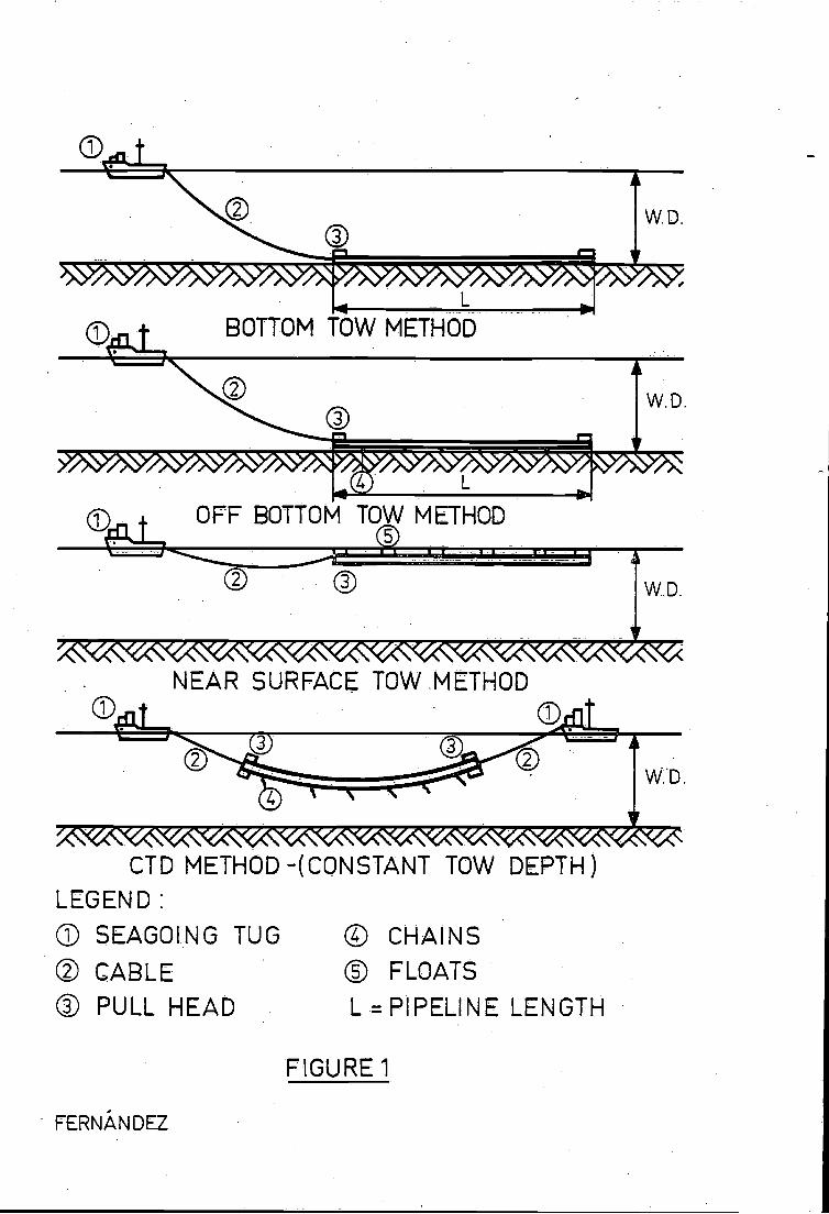
going tugs, as shown in Figure 1. The methods may be listed as follows:
Bottom tow
Off-bottom tow
Surface tow
Constant tow depth (CTD) or sub-surface tow
Regardless of which of these methods is employed, their main feature or restriction
is the limited length of pipe that can be towed. However, the increasing use of
subsea completions, the continuing development of deepwater fields, and the
growing utilization of early production systems - all of whch require the
installation of relatively short-length marine pipelines are effective in promoting
the adoption of tow techniques. For towing and maneuvering operations, the tow
forces are constrained by the performance capabilities of existing equipment.
Typically, tow vessels are limited to less than 2000 kN (220 Tons) bollard pull,
* Delft University of Technology, Delft, The Netherlands.
and to speeds to between 2 and 6 knots (I to 3 m/s). Where winch barges or
onshore pull winches are employed, then pull speeds are further restricted, but pull
forces can be increased up to 8000 kN (880 Tons) at pull speeds. of 5 to 15 rn/mm..
The prime features and advantages of tow techniques are:
- Manipulation of pipelines during towing is relatively easy and safe regardless of
water depths or pipe characteristics. Excessive bending or damage during
installation can be avoided, and pipeline stresses can be maintained at low,
safe levels throughout towing.
- Considerable reductions in pipeline installation time can be achieved in contrast
to conventional lay barge methods. Tow vessels by comparison, are fast and their
relatively small size assists in giving them outstanding maneuverability.
Large diameter and heavy pipe can be installed, as can bundled or otherwise
difficult pipe configurations. These designs would be slow or impossible to
install by lay barge.
If first or second end (i.e. leading and trailing end) connections are feasible1
preferably using mechanical connectors, then significant reductions in construction
time and cost can be achieved relative to traditional tie-in methods. These
connection methods do not require spool pieces or sophisticated procedures, nor
do they involve large tie-in spreads.. Apart from the pipelines, tow vessel and
standard support and survey systems, little additional surface based equipment is
needed. The pipeline length must, however, be properly designed.
Representative cases for the installation of marine pipelines where employment of
tow techniques is recommended, or may be mandatory, can be. surnlmarized aS
follows:
Shore approaches, near shore, in shallow or very shallow water where
installation by lay barge is not possible.
- For complex pipe. bundles or very large diameter lines, i.e. over 1500 mm
(60 inches) which are difficult to handle by lay barge [11 2 1.
3
- Where difficult or dangerous maneuvering by 1ay barge is required, especially as
regards anchor handling, for example in areas of rocky seabed, near platforms
and in other locations heavily populated with pipelines [3 1.
- In very deep waters where existing lay barges may be incapadtated by
limitations in tensioner gear, stinger geometry or barge positioning [4, 5]
- In arctic areas with heavy ice cover [ 4, 6]
- Where, because of high sea states or other excessive environmental conditions,
only a short or indeterminate installation season is available.
A systematic approach, as described below, is recâmmended when assessing the
application of tow techniques to pipeline installation. This is followed by a
discussion of each of the tow methods in terms of their prime fealures, their
advantages and disadvantages, and the considerations entailed in pipeline design
and construction. Certain of the views expressed in this paper qre based on the
author's personal involvement and experience with various pipeline tow projects
during their design and/or construction phases.
METHODOLOGY
For a marine pipeline system, the main objective is to be able to install and
operate the line with the minimum of risk. Pipeline installation by one of the tow
methods requires a different sequence of design and construction phases than con-
venflonal installation. The basic phases which must be individually checked to
ensure successful performance comprise fabrication, tow, connection, and operating
conditions.
Phase 1) Onshore fabrication: This involves pipe make-up facilities and a
launchway, and the line may frequently be fabricated as a series of long strings
which are welded together when the pipe is launched into the water. If possible
however, the line should be fabricated as a single string, enabling the entire
system to be hydrotested onshore and launched more quickly. During handling and
launching of the pipeline, its weight out of the water is considerably greater
4
than later when it. is:submerged. The weight must be strictly controlled within
small tolerances during fabrication. This is because both the negative buoyancy
and the tow forces are sensitive to variations in weight. The use of correct
launchway design and construction procedures is beneficial in avoiding the
need for excessive forces or the possibility of overstressing the pipe.
- Phase 2) Tow or transportation to offshore location: Adequate seabed information
is needed to enable selection of the tow methQd and/or route which will ensure
safe levels of pipe stress uring towing, with limited bending of the pipe string
and acceptable tension levels. Where the route passes through deep water, the
application of increased internal pressure to the pipeline can be used to achieve
a reasonable margin of safely against bucklfng or excessive strains resulting from
the external hydrostatic pressure.
Phase 3) Connection or tie-in: After tow-out, the pipeline is ready for
connection to the subsea system, utilizing either conventional tie-in methods, or
by first and second end connection methods. The leading end connection should
be performed usiflg controlled manipulation of the pipe and without delay [4]
For the second, or trailing end connection, an accurate seabed survey and
-precise positioning of the connection point are required when determining pipe-
line length. If the pipeline is too long, the pipe may be overstressed; and if
too short, it may be dfficult to execute the connection.
A careful analysis and accurate calculation are needed to minimize the risks
inherent in incorrect design of pipeline length, especially when contrasted
against reliable but more expensive conventional tie-n methods. In general it is
feasible to attain the main advantages of second end connection, namely speed
of completion, reduced cosls, and an acceptable degree of reliability.
Before operating the line, additional design and construction activities can be
introduced, such as when trenching or burial of the line, either before or after
5
tie-in, is recommended.1 These aspects however, are outside the scope of this
paper.
Phase 4) Operating condiflons: The safe operation of a pipeline s based on
correct forecasting and assessment of the extreme conditions likely to be imposed
on the line. A pipeline may be subjected to stresses arising from some or all of the
following:
The final position or geometry of the line, including pipe restraints and
boundary conditions
Gravitational and hydrodynamic forces on the pipe, which may be important
if spans have developed in the line as a result either of construction
activities or of the seabed configuration and soil conditions
Internal operating pressure
External hydrostatic pressure
Restraints on the line when thermal expansion occurs as a result of temperature
variations between the pipe contents and the sea: water.
Conventional tie-in methods may be designed to function as a stress-relieving
system, but if tie-in is by means of trailing-end connection, then the entire
system must absorb all stresses resulting from the operating conditions. For
comprehensive design, the stresses must be checked for each of the various
construction phases.
The following are the prerequisites of successful pipeline installation when
employing a tow method:
- Careful planning and scheduling covering engineedng, design, construction
procedures, and onshore qnd offshore field preparation.
'Sometimes, there are not technical or safely reasons or government regulations
for trenching or burying a submarine pipeline.
6
- Adequate and reliable construction equipment, including survey equipment (i.e.
vessel insfrumentation systems), the tow vessel (as regards winches and cables),
diving support equipment and one or more submersibles.
As Phases and 4, covering onshore fabrication and pipeline operating conditions,
are normally predetermined by the nalure and location of a specific project, only
Phase 2, concerning tow-out to site is discussed in detail hereunder. For Phase 3,
discussion centers on the traiUng-end connection method in order to emphasize the
importance of correctly forecasting the geometry or final configuration of the pipe.
No reference is made to problems that may be experienced as a result either of
pipeline vibration that may be caused by vortex shedding, or the effecis of
corrosion or fatigue on the behavior of materials.
BOTTOM TOW
The bottom pull method has been extensively employed on marine pipeline prolecis,
and has established an excellent reliabilily record. Typically this method employs
winches at fixed locations such as onshore, on anchored barges and, more recently,
on platforms where it has been used to perform tie-ins. In the near fulure, it willalso be used on ice platforms for installing offshore pipelines in the Arctic.
With the bottom tow method, as shown in FTgue 1, a pipeline is towed along the
seabed by a tug to which it is attached by a long cable.. The line may be a
single pipe or a bundle of pipes, as illustrated in Figure 2. From vertical and
horizontal equilibrium, the maximum length of pipeline that can be towed using
available tow vessels, may be estimated by assuming: firstly that the pipe bottom
is in direct and continuous contact with the seabed, with no spans being present;
secondly that the system has a uniform negative buoyancy along us entire length;
and thirdly, that the coefficien1 of friction between the pipe and the tow route
are known, based on reliable data concerning the seabed soils configuration and
the pipe characteristics.
7
Seabed and Route Selection
A detailed marine survey is required to enable selection of the tow route corridor
from the pipe launchway to the location for final pipe positioning. The width of
the corridor is a function of the accuracy and tolerance of the positioning system
and survey equipment. The planned and actual tow routes must be checked for the
presence of any maritime hazards..
The seabed along the tow route should preferably be relatively flat and straight,
and be free of obstructions such as sharp depressiqns or elevations, rock outcrops,
ship wrecks, and subsea struclures. Allowable, span lengths, and minimum horizontal
bending of the pipeline must be calculated as criteria for route selection. The to
limiting conditions are considered as being when the pipe 'i. at rest without tension,.
and moving under tow.
To ease the task of a design analysis and route selection, it is feasible to reduce
possible variely in lypes of soils along the route by grouping them into convenient
categories. This tactic should still enable acceptable forecasting of the lateral
and longitudinal friction coefficients needed for calculation of stabilily on the
seabed and the magnitude of the tow forces. For estimating the conditions when
the pipe is static; at the start of towing; and the dynamic case where the pipe is
being towed; it' is necessary to have a knowledge of the extremes- of longitudinal
coefficient. Because of continuous variations ifl the seabed configuration and soils
along the tow route., there. are corresponding variations in the friction coefficients
and dynamic tow forces. For a given lype of soil, the starting friction forces are
larger than the dynamic friction forces, In particular with cohesive soils, the ratio
of these forces may be as high as 3 1.
The. formulae for evaluation of skin friction coefficients for cohesive, and non-
cohesive soils have been developed and documented by Potyondy [7] . In the case
of submarine pipelines, other factors contributing to determination of the friction
coefficients are:
8-
- Smoothness of pipe surface, which is important when estimating the adhesion
with cohesive soils..
- Settlement of and/or grooving by the pipe in the seabed, this being a function
of the soft's load-bearing capacily, the pipe characteristics, and the negative
buoyancy.
Pipe Stability
To maximize the pipeline length and/or optimize the tow speeds and forces for
long distance bottom tow by tugs, the negative buoyancy of the system must be
minimized. The negative bUoyancy and stability of the. line are. determined by risk
analysis rather than by standard stabilily criteria. To quantify the risks, the
following factors may be taken into consideration:
- The contents of the pipeline, e.g. water, gas or crude oil, during and after
installation, and in the. operating condition.
The expected maximum bottom current velocities during tow-out and operation of
the line.
- The possible use of a holdback, tension vessel during tow-out, or a holdback
anchor when stationary, to enhance stabitily.
The possible use of pipe burial, trenching or anchoring following tow-out.
For weightcoated pipes, the spoIlage, abrasion and water absorption of the
concrete
- The probable need for a more reliable survey when weight-coated pipe is being
used.
Strict control of weight and dimensional tolerances during pipe manufacture and the
application of protective or weight coatings, is recommended. The negative
buoyancy, and hence also pipe stability and tow-out, are very sensitive to small
changes in weight. For an accurate estimate of the negative buoyancy obtained
during installation, every item which contributes to the weight must be considered
9
and checked. This operation, which is in addition to the strict confrol of weight
during fabrication, should include:
Seawater densily and temperalure, to facflitdte evaluation of positive buoyancy
Line pipe, steel physical properties, including welds
- Anti-corrosion protection, including coatings, anodes and ancillary equipment
- Pipe contenft, such as pressurizing gas
Pulling head, sled and ancillary equipment
- Equipment, such as pontoons or tanks, cables or chains and attachment lugs, for
increasing or decreasing the buoyancy
Spacers and ancillary equipment required for bundled lines
Concrete derisily, thickness, abrasion, spallage, water absorption and steel
reinforcement for weight-coated pipe
- Field joinis, i.e. mastic, steel wrap-around etc.
In areas of high current velocily, such as shore approaches and river crossings,
heavyweight pipe and weight coating are usually recommended. The negative
buoyancy of the system is normally determined by means of a standard stabilily
analysis; and installation is performed using pull winches positioned at a fixed
location. Considering the lypical speed of a bottom pull and the probably detailed
knowledge of the pull route, abrasion and spallage in this. case are likely to be
sufficiently small as to be neglected.
Link Cable and Alternative. Bottom Tow Method
Selecti9n of the link cable and forecasting the cable geometry and related para-
metCrs, can be done using normal cafenory equations. The known factors are: the
available tow forces; tow speeds; drag forces n the cables as per Ku lIen [81 or
similar references; and the cable properties. The cable must transmit only axial
forces to the pipeline. Torsional forces originating from possible cable spin or
- 10 -
stretch should be avoided by installing a swivel at the connection point between
the cable and pipe pulihead.
Compared with the length of cable necessary to maintain the puliheadon the sea
bottom, shown in Figure 1 Bottom Tow, considerable reductions in link cable
length can be achieved by carefully lifting the pullhead off the bottom after
towing has commenced. This modified bottom tow method, which is shown in
Figure 3, offers the following additional advantages:
- Reduced abrasion and friction forces on the cable as it is no longer in contact
with the seabed
Enhanced control, positioning and maneuverability of the pipeline because of the
reduced cable length
Some reduction in the longi1tdinal friction forces because the pipeline is lifted
off the bottom under tension
As identified in Figure 3, tow parameters such as the lift-off distance 'Y'; the
tensions at poin1 '1' and '2'; and the maximum stresses at section '2' - '3', may,with some assumptions, be obtained from the equilibrium equations of the system
and by use of the following procedures:
Normal catenary equations for the link cable over section '1' - '2'.
Equations derived from elastic beam theory and small deflections for section
'2' - '3' of the suspended pipe: these are solved for boundary conditions where
the pipeline is horizontal on the seabed from touchdown point '3'; and where
there are no bending moments at '3' or at the pipe end '2'. (For further details,
see analysis of the constant tow depth method).
The horizontal and vertical eqtiBbrium of section '3' - '4'.
The operational differences between the 'conventional' and 'modified' bottom tow
methods, may be summarized as follows:
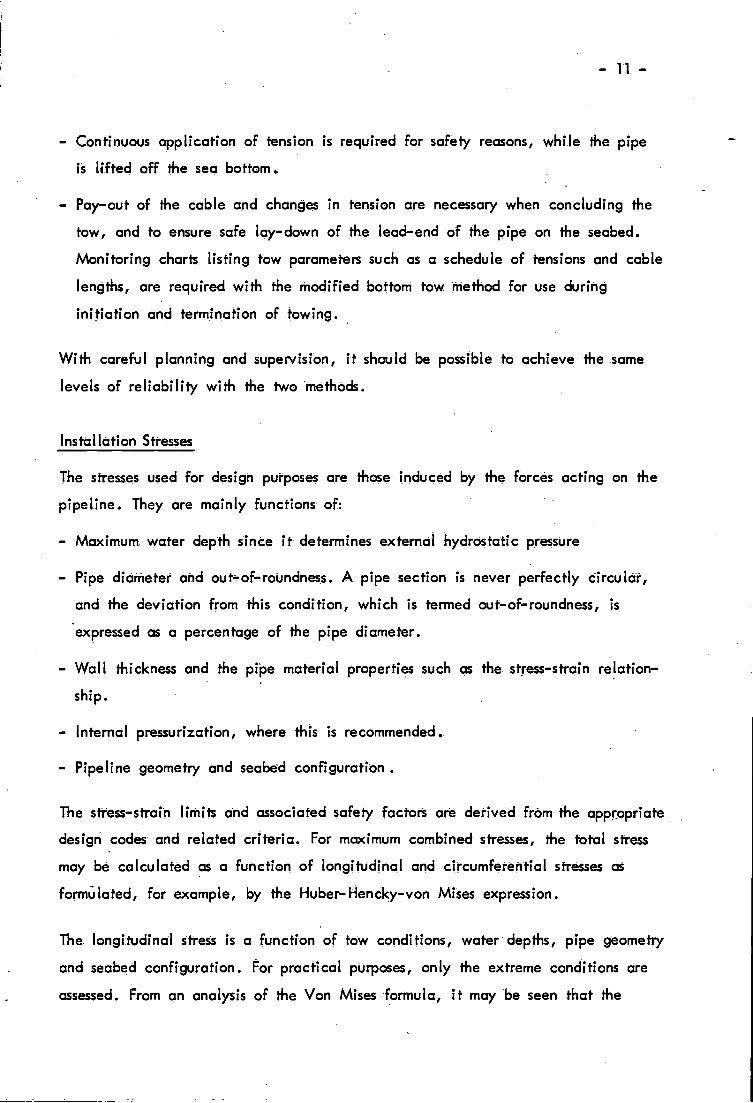
Continuous application of tension is required for safely reasons, while the pipe
is lifted off the sea bottom.
Pay-out of the cable and changes in tension are necessary when concluding the
tow, and to ensure safe lay-down of the lead-end of the pipe on the seabed.
Monitoring charts listing tow parameters such as a schedule of tensions and cable
lengths, are required with the modified bottom tow. method for use during
initiation and termination of towing.
With careful planning and supervision, it should be possible to achieve the same
levels of reliability with the Iwo methods.
Installation Stresses
The stresses used for design purposes are those induced by the forces acting on the
pipeline. They are mainly functions of:
- Maximum. water depth since it determines external hydrostatic pressure
- Pipe diameter and ouFof-roundness. A pipe section is never perfectly circula,
and the deviation from this condition, which is termed out-of-roundness, is
expressed as a percentage of the pipe diameter.
- Wall thickness and the pipe material properties such as the stress-strain relation-
ship.
- Internal pressurization, where this is recommended.
- Pipeline geometry and seabed configuration.
The. stress-strain limils and associated safely factors are derived from the appropriate
design codes and related criteria. For maximum combined stresses, the total stress
may be calculated as a function of longitudinal and circumferential stresses as
formulated, for example, by the Huber-Hencky-von Mses expression.
The longitudinal stress is a function of tow conditions, water depths, pipe geometry
and seabed configuration. For practical purposes, only the extreme conditions gre
assessed. From an analysis of the Von Mises formula, it may be seen that the
- 12
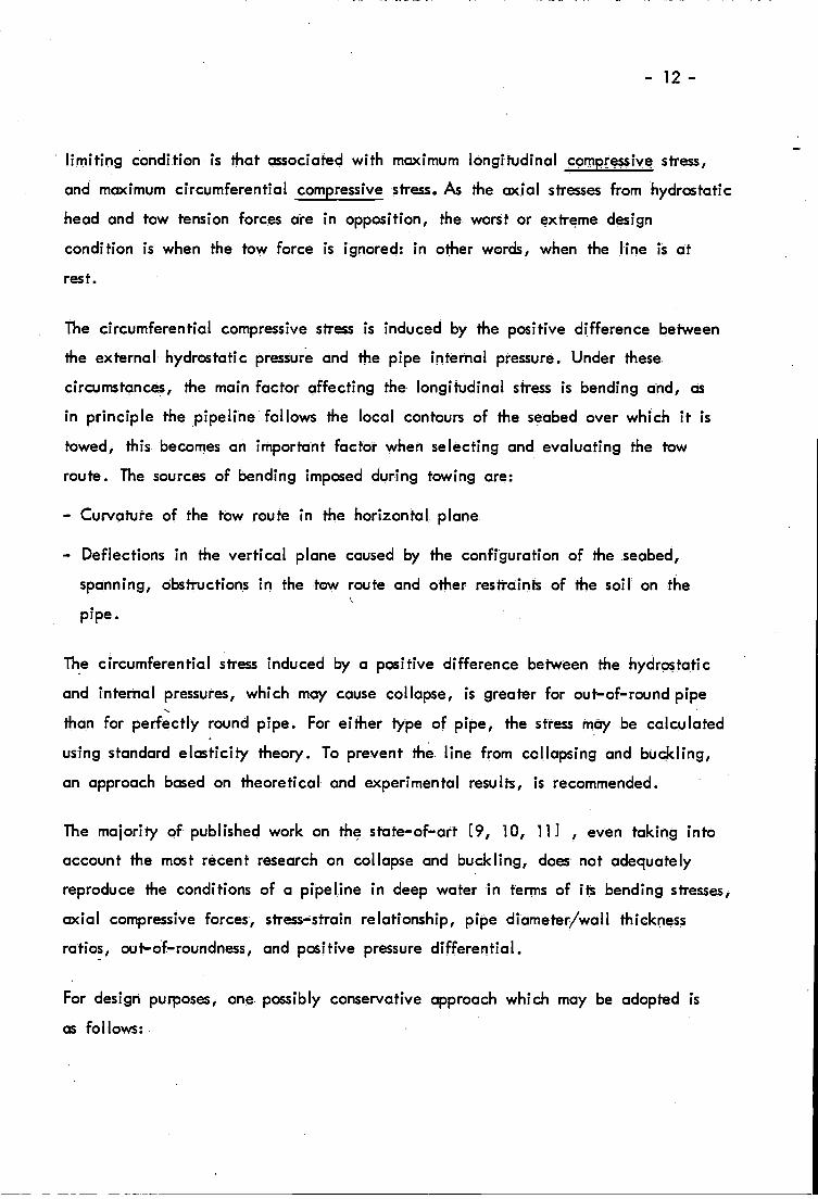
limiting condition is that associated with maximum longitudinal compressive stress,
and maximum circumferential compressive stress. As the ax!al stresses from hydrostatic
head and tow tension forces are in opposition, the worst or extreme design
condition is when the tow force is ignored: in other words, when the line is at
rest.
The circumferential compressive stress is induced by the positive difference between
the external hydrostatic pressure and the pipe internal pressure. Under these.
circumstcnces, the main factor affecting the longitudinal stress is bending and, as
in principle the pipeline follows the local contours of the seabed over which it is
towed, this. becomes' on important factor when selecting and evaluating the tow
route. The sources of bending imposed during towing are:
- Curvalure of the tow route in the horizontal, plane.
- Deflections in the vertical plane caused by the configuration of the seabed,
spanning, obstructions in the tow route and other restraints of the soil on the
pipe.
The circumferential stress induced by a positive difference between the hydrostatic
and internal pressures, which may cause collapse, is greater for out-of-round pipe
than for perfectly round pipe. For either type of pipe, the stress may be calculated
using standard elasticily theory. To prevent the line from collapsing and buckling,
an approach based on theoretical and experimental results, is recommended.
The majority of published work on the state-of-art [9, 10, 1 11 , even taking into
account the most recent research on collapse and buckling, does not adequately
reproduce the conditions of a pipeline in deep water in terms of its bending stresses1
axial compressive forces, stress-strain relationship, pipe diameter/wall thickness
ratios, out-of-roundness, and positive pressure differential.
For design purposes, one possibly conservative approach which may be adopted is
as follows:.
- 14 -
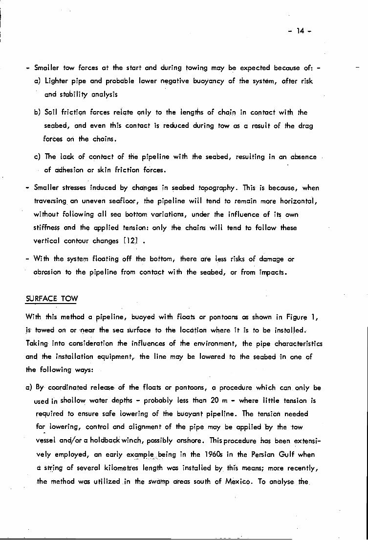
Smaller tow forces at the start and during towing may be expected because of: -
Lighter pipe and probable lower negative buoyancy of the system., after risk
and stability analysis
Soi.l friction forces relate only to the lengths of chain in cofltact with the
seabed, and even this contact is reduced during tow as a result of the drag
forces on the chains.
The lack of contact of the pipeline with the seabed, resulting in an absence
of adhesion or skin friction forces.
Smaller stresses induced by changes in seabed topography. This is because1 when
traversing an uneven seafloor, the pipeline will tend to remain more horizontal,
without following all sea bottom variations, under the influence of its own
stiffness and the applied tension: only the chains will tend to follow these
vertical contour changes [12]
With the system floating off the bottom1 there are less risks of damage or
abrasion to the pipeline from contac.t with the seabed, or from mpacts.
SURFACE TOW
With this method a pipe Une, buoyed with floats or pontoons as shown in Figure 1,
is towed on or neai the sea surface to the location where. it is to be installed.
Taking into consideration the influences of the environment, the pipe characteristics
and the installation equipment,. the line may be lowered to the seabed in one of
the following ways:
a) By coordinated release. of the floats or pontoons, a procedure which can only be
used in shallow water depths - probably less than 20 m - where little tension is
required to ensure safe lowering of the buoyant pipeline. The :tension needed
for lowering, control and alignment of the pipe may be applied by the tow
vessel and/or a hol.dback winch, possibly onshore. This procedure has been extensi-
vel.y employed, an early example..being in the 196C in the Persian Gulf when
a string of several kilomefres length was installed by. this means; more recently,
the method was utilized .in the swamp areas south of Mexico. To analyse the
15 -
suspended pipe and program the release of the floats, simple beam theory may
be used in view of the relatively small deflections involved. Alternatively, the
method represented by Konuk [131 and based on rod theories, is particularly
appropriate where a heavy pipeline has to be installed under conditions of low
tension.
By taking the pipe strings consecutively onboard a lay barge; detaching the
floats or pontoons; welding the string ends and progressively lowering the pipe-
line to the seabed. This technique is especially relevant in deep waters where
use would be made of a dynamically-positioned lay barge equipped with tensioner
gear and a stinger [5 1 . Under favorable weather conditions, when it is feasible
to use long pipe strings, this method can achieve very high laying rates.
By taking the pipe strings consecutively oflboard a barge, replacing the
pontoons with variable-buoyancy floats, welding the string ends and progressively
lowering the pipeline to the seabed. Because the voriable-buoyancy.system
remains attached to the line during the lowering process, very little tension
needs be applied at the surface and the barge is not re4uired to have a stinger.
As with the previous method, relatively long pipe strings may be used.
Patented nearly 20 years ago, and called the 'S' curve method, this technique
has been employed for laying in very deep waters [5)
The surface tow method differs from the other tow procedures in that it is also a
laying procedure. Its main disadvantage is the sensftivily of the buoyant pipeline
to weather conditions. Wind and waves can greatly disturb not only the tow, but
also the welding and laying operations. Where other tow methods are feasible, the
surface tow technique may be uncompetitive because of its need for a lay barge.
This method may also be rendered too expensive when it is used in conjunction
with first and second end connection of the pipe. With the tow-out floats removed,
the line will become heavier and difficult to maneuver on the seabed, thus
entailing the additional cost of fitting new floats specially for this purpose. A
further disadvantage can be the difficulty involved in handling pipeline bundles
for welding on the barge.
- 16 -
Conversely, where there is If ttle risk of bad weather, surface tow can offer an
atfractive solution: for example, in shallow protected waters, method 'a' which
requires only a small surface spread to perform the coordinated release of the
buoyancy pontoons, is particularly appropriate.
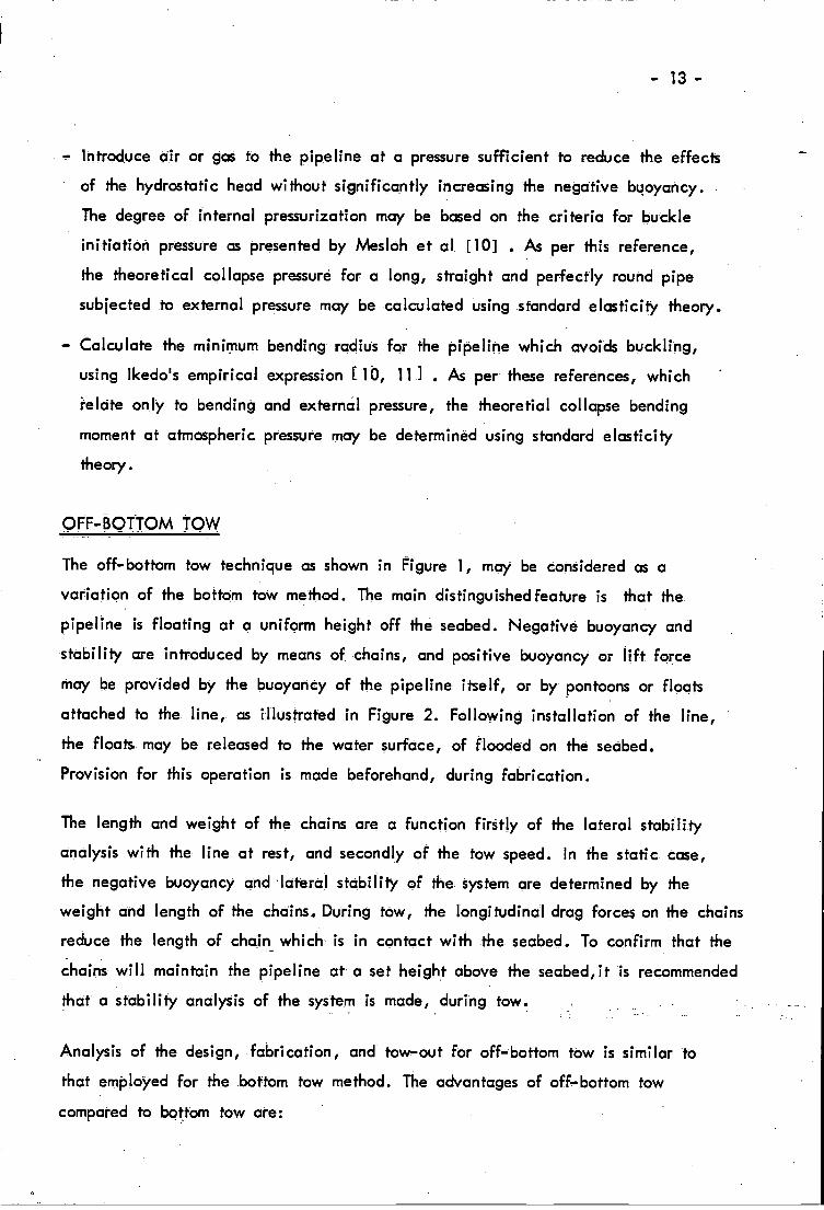
CONSTANT TOW DEPTH METHOD
As the most recently developed tow technique, the constant tow depth (CTD)
method, as shown in Figure 1, is effectively a variant of the off-bottom tow
method. Fabrication, stability, stress analysis and the limiting design considerations
are identical to those developed for off-bottom tow: only the method of trans-
portation is different.
By infroducirig tension with a holdback vessel, the pipeline system is elevated in a
symmetrical curve to any desired height above the seabed. Both the tow vessel at
the front and the holdback vessel at the rear apply tension to the pipe continuous-
ly throughout tow-out Although the pipeline system in fj suspended condition may
be relatively light, the required tension levels are quite high. However, they are
probably lower than the tow forces for a system in contact with the seabed, and
ensure safe maneuverability and low longiludinal stresses during transportation.
The reliabiliiy.of the CTD method was recently and successfully confirmed during
installation of some pipelines in the UK Sector of the North Sea. The technique is
ideal for deepwater installations and long dstance towing and, in addition to
offering all the advantages of the off-bottom tow method, also provides the benefii
that:
The entire system of pipeline and chains is lifted off the seabed, totally freeing
it of the problems related to the bottom configuration and potential obstructions
such as ship wrecks, rock outcrops and other pipeUnes or cables.
- Selection of the tow route is easier, and a less rigorous and probably less
expensive survey is necessary before and during transportation than for the bottom
tow method.
- 17 -
- Smaller tow forces are required thcn for tow methods where the pipeline is in
contact with the seabed: also, smaller longtudinal stresses can be guaranteed.
It has been demonstrated by, among others, Reid [14] in 1951, and Brando and
Sebastiani [15] in 1971, that for a submerged slender lightweight pipeline sub-
jected to a large axial tension, the stiffness of the line may be neglected,
enabling it to be treated as a catenary. Acceptable limits for the validiiy of
catenary equations with a suspended pipeline have been established as a function
of pipe stiffness, length, tension and negative buoyancy.
For the purposes of formulation, the pipeline and link cables may be considered as
combined cateriaries, symmetrical about the mid-point of the pipe. For a given tow
speed, the increased drag force of the suspended system is added to the cable
tension at the tow vessel. The bending stresses in the pipe may be determined
from the curvaKire of the line.
To prepare tow procedures and monitor the tow-out and pipeline installation, tow
parameters are calculated listing pipe geometry, the position of the line relative
to the seabed, and tow and holdback cable lengths for different tow speed and
tension forces at the tow and holdback vessels. Results observed during aclual
installation by the CTD method have been found to be comparable. to forecast data
using the catenary approach..
Rnfte element techniques or rod theories [131 may be used for analysis of
undesirable or extreme conditions as regards insufficient tension, too heavy a
pipeline, or exessive bending. If the reliabilily of the catenary analysis in safe-
guarding the integrity of the pipeline is accepted then, when using the CTD method of
installation, a more general formulation [16] may not be necessary.
SECOND END CONNECTION
The second end, or trailing end connection technique may be employed with single
or bundled pipelines where there is a relatively short distance between the two
structures to be connected, such as between a welihead and/or platform, SPM or
- 18 -
central manifold, etc. Not considered here are second end connections which
require the use of a swivel connection [17] or flexible pipe comprising alternate
layers of plastic and steel. While some of the design difficulties have been
presented before [9, 18] , the following is intended to emphasize the more promi-
nent design and construction prerequisites for the safe accomplishment of pipeline
connection and operation.
To perform first and second end connection, it is preferable to have a light and
flexible pipeline system to assist in minimizing pipe pull forces and bending loads
[4 1. By virtue of their use of a stable system, elevated off the seabed and in
contact with the bottom via chains uniformly distributed along the length of the
pipe, the CTD and off-bottom tow methods both offer these benefib during the
connection phase. By contrast, the other tow techniques require costly in-place
preparations.
For tow-out, submersibles and diving support are helpful in providing route
selection and survey data: for first and second end connections, the assistance of
such equipment is invaluable. Here, their functions may include:
As-built survey and inspection of the pipeline before, during and after connection.
Subsea installation of rigging needed for connection of the line, and attachment
and disconnection of tow/pull cables.
Inspection of the seabed as regards soils, scour, pipe spans etc.
- Sand bagging of the line
Emergency seiv ices.
The pipe geometry and pull forces are very sensitive to soil characteristics, seabed
configuration, chain properties, pipe buoyancy, and survey accuracy. The
acquition of data relating to these variouS elements - which is not always easy -
and their subsequent modeling, must be performed with great care to avoid the use
of incorrect boundary conditions in lurn leading to incorrect solutions. It is also
important to check the operating conditions that will obtain when the pipeline is
- 19 -
in i1 second-end connection configuration as these can interact with the prior
design phases.
A theoretical analysis can assist in identifying the optimUm consfruction procedures,
and in specifying the lypes of equipment needed to perform the tow/pull-in
connections of the pipe ends. The advantages of this method have already been
emphasized.
CONCLUSIONS
The four tow techniques are each technically feasible. For a given location,
selection of the installation method to be used should be based on a thorough
evaluation of the likely alternative consfruction procedures. As outlined in this
paper, each method has its own advantages and limitations, and the best solution
may be found when these are related to the known boundary conditions of the
particular installation. A technical assessment and cost estimate will indicate the
feasibilily of, and risks attaching to, each of the tow techniques, and in some
instances will identify positive reasons promoting a particular method.
***********-****
- 20 -
REFERENCES
1 Gombert, D.W., "Huge Subsea Pipe Bundle Installed from Shore" The Oil and
Gas Journal, August4, 1975, pp 60-64
2 Menezes, P.F. de, "Emissarfo Submarino de Santos, Brazil: Operaçao
Puxament&', DAE Journal, No 116, 1978, pp 24-27
3 Staff reporter, "Bottom-tow Holds Influential Impact", Offshore, July 1977,
pp 48-53
4 Brown, R.J., "Pipeline Stabilization and Automated Connection", paper
presented at the "1980 European Seminar,Offshore Oil and Gas Pipeline
Technology", London, 1980
5 Staff reporter, "R.A.T. Pipelaying Method Passes TeSt in North Sea",
Pipeline & Gas Journal, October 1977, pp 49-52
6 Staff reporter, "Tomorrow's Frontiers - Today's Experience", Nóroil, May 198O
pp. 1I1-116
7 Potyondy, J.G., "Skin Friction Between Various Soils and Consfruction
Materials", Geoteçhnique, Vol. Xl, The Institution of Civil Engineers, 1961,
pp 339-353
8 Kullemberg, B., "Shape of Trawling Cable", Report of the Swedish Deep Sea
Expedition, Vol. III, No 2
9 -Fernández, M.L. and Carlson, W.O., "Theory and Practice in Deep Water
Pipe Laying", paper presented at the "1980 European Seminar, Offshore Oil
and Gas Pipeline Technology", London, 1980
- 21 -
10 Mesloh, R., Johns, T.G. and Sorenson, J.E., "The Propagating Buckle",
Proceedings Boss '76, The Norwegian Institute of Technology, 1976,
pp 787-797
11 NASA TND-1510, "Collected Papers on Instabilily of Steel Structures",
Langley Research Center, Virginia
12 Kennel, L. and Chauvaux, G., "L.aying Underwater Pipelines by Float and
Chains Method", Ocean ResDurces Engineering Journal, April 1978
13 Konuk, I., "Higher Order Approximations in Stress Analysis of Submarine
Pipelines", ASME paper No 80-PeF-72, 1980
14 Reid, R.O., "Some Oceanographic and Engineering Considerations in Marine
Pipeline Construction", Proceedings Second Conference on Coastal
Engineeri ng, Chapter 28., 1951, pp 325-393
15 Brando, P. and Sebastidni, G., "Determination of Seal ines Elastic Curves
and Stresses to be Expected During Laying Conditions", Proceecli ngs f the
Offt Technology Conference, Paper OTC 1354, 1971
16 Kan1 W.C. and Healey, A.J., "Finite Element Analysis with the State
Variable Transfer Matrix and Geometric Non- I meanly for Marine Pipelines
n Sub Surface Tow", ASME Paper No 80-Pet-47, 1980
17 Pros, S., Lévellois, E. and Gouraud, 0., "Second End Flowline
Connection Without Length Adjustment", Proceedings of the Offshore
Technology Conference, Paper OTC 3074, 1978
18 Hibbitt, H.D., Becker, E.B. and Taylor, L.M., "Non Linear Analysis of
Some Slender Pipe1 ines", Computer Methods in AppI, led Mechgni s and
Engineering, Vol. 17, North Holland, 1979, pp 203-225
BOTTOM TOW METHOD
FERNANDEZ
OFF BOTTOM TOW METHOD
© ©
NEAR SURFACE TOW METHOD
W.D.
W.D.
WD.
CTDMETHOD-(CQNSTANT TOW DEPTH)LEGEND:
SEAGOING TUG © CHAINS© CABLE ® FLOATS® PULL HEAD L=PIPELINE LENGTH
FiGURE 1
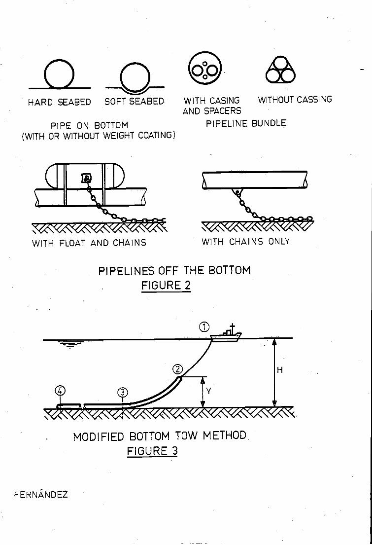
HARD SEABED
PIPE ON BOTTOM(WITH OR WITHOUT WEIGHT COATING)
WITH FLOAT AND CHAINS
FERNÁNDEZ
C-SOFT SEABED
PIPELINES OFF THE BOTTOMFIGURE 2
MODIFIED BOTTOM TOW METHOD.FIGURE 3
WITH CASINGAND SPACERS
PIPELINE BUNDLE
WITH CHAINS ONLY
WITHOUT CASSI NG


![irp-cdn.multiscreensite.comC] Company certificate number C] TDLR license number of the tow o erator Tow company must maintain the following information for each non-consent tow (does](https://img.pdfslide.us/doc/110x75/60009680cd663601f534d4e4/irp-cdn-c-company-certificate-number-c-tdlr-license-number-of-the-tow-o-erator.jpg)