Embed Size (px)
Citation preview
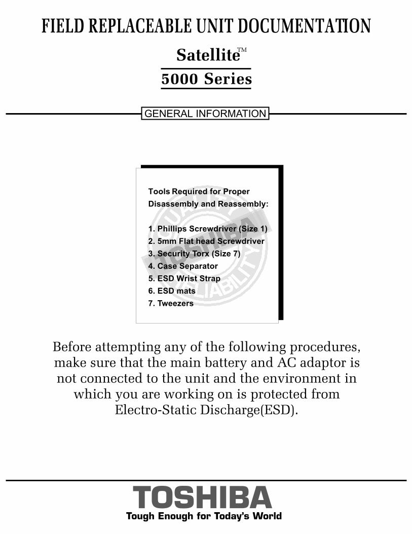
Tough Enough for Today’s World
FIELD REPLACEABLE UNIT DOCUMENTATION
5000 Series
GENERAL INFORMATION
Before attempting any of the following procedures,make sure that the main battery and AC adaptor is not connected to the unit and the environment in
which you are working on is protected fromElectro-Static Discharge(ESD).
TOSHIBATough Enough for Today’s World
FIELD REPLACEABLE UNIT DOCUMENTATION
5000 Series
GENERAL INFORMATION
Before attempting any of the following procedures,make sure that the main battery and AC adaptor is not connected to the unit and the environment in
which you are working on is protected fromElectro-Static Discharge(ESD).
TOSHIBA
Tools Required for Proper
Disassembly and Reassembly:
1. Phillips Screwdriver (Size 1)
2. 5mm Flat head Screwdriver
3. Security Torx (Size 7)
4. Case Separator
5. ESD Wrist Strap
6. ESD mats
7. Tweezers
SatelliteTM
TOSHIBATough Enough for Today’s World
TABLE OF CONTENTS:
1. BATTERY PACK REMOVAL
2. OPTIONAL PC CARD REMOVAL
3. HDD REMOVAL
4. MEMORY MODULE REMOVAL
5. MINI PCI CARD REMOVAL
6. MODEM BOARD REMOVAL
7. KEYBOARD REMOVAL
8. TOP COVER REMOVAL
9. CD-R/W//DVD-ROM DRIVE REMOVAL
10. SPEAKER(WOOFER) REMOVAL
11. SOUND BOARD REMOVAL
12. BATTERY BOARD REMOVAL
13. RTC REMOVAL
14. SECURE DIGITAL(SD) BOARD REMOVAL
15. VIDEO BOARD REMOVAL
16. COOLING MODULE REMOVAL
17. CPU REMOVAL
18. SYSTEM BOARD REMOVAL
19. TOUCHPAD REMOVAL
20. INTERFACE BOARD REMOVAL
21. CD CONTROL/SUB LCD REMOVAL
22. SENSOR SWITCH REMOVAL
23. SPEAKERS REMOVAL
24. 15’’ DISPLAY MASK REMOVAL
25. FL INVERTER AND 15’’ LCD REMOVAL
FIELD REPLACEABLE UNIT DOCUMENTATION
5000 Series Satellite
TM
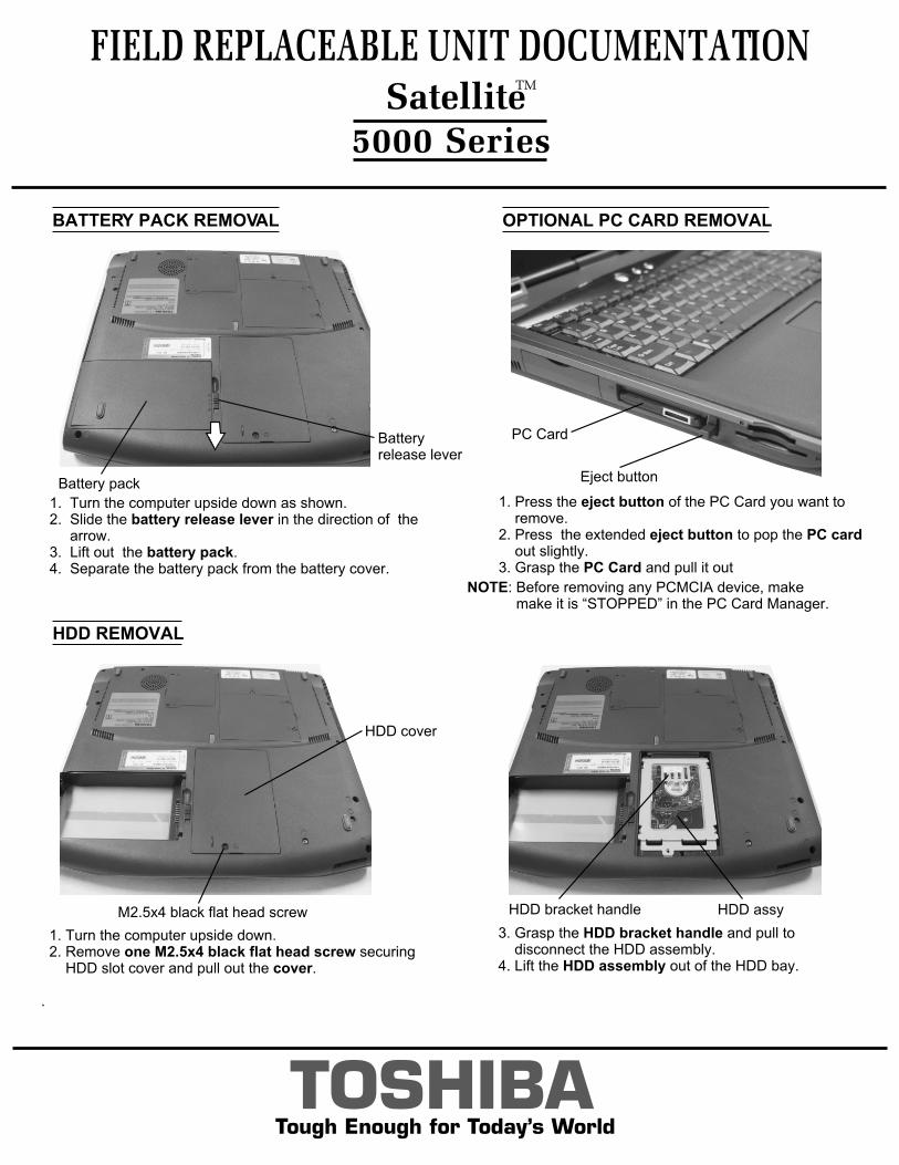
BATTERY PACK REMOVAL OPTIONAL PC CARD REMOVAL
TOSHIBATough Enough for Today’s World
1. Turn the computer upside down as shown.2. Slide the battery release lever in the direction of the arrow. 3. Lift out the battery pack.4. Separate the battery pack from the battery cover.
1. Press the eject button of the PC Card you want to remove.2. Press the extended eject button to pop the PC card out slightly.3. Grasp the PC Card and pull it out
HDD REMOVAL
3. Grasp the HDD bracket handle and pull to disconnect the HDD assembly.4. Lift the HDD assembly out of the HDD bay.
1. Turn the computer upside down. 2. Remove one M2.5x4 black flat head screw securing HDD slot cover and pull out the cover.
.
NOTE: Before removing any PCMCIA device, make make it is “STOPPED” in the PC Card Manager.
FIELD REPLACEABLE UNIT DOCUMENTATION
5000 Series
Batteryrelease lever
Battery pack
PC Card
Eject button
HDD cover
M2.5x4 black flat head screw HDD assyHDD bracket handle
SatelliteTM
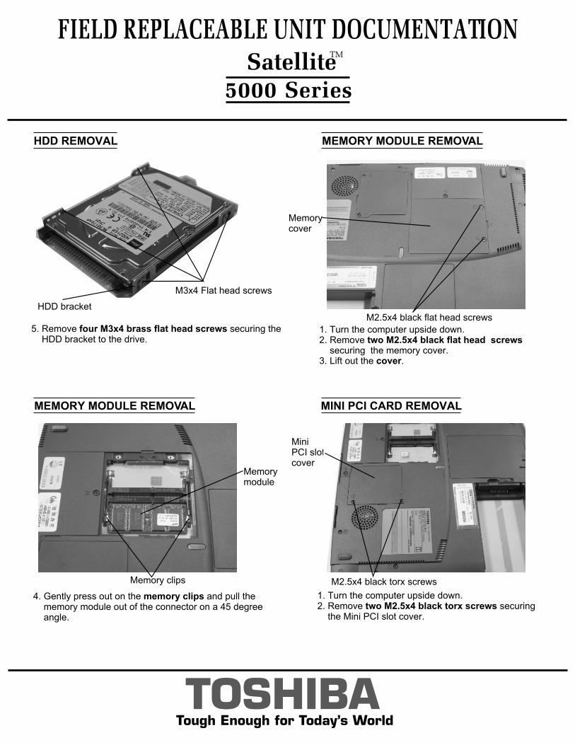
MEMORY MODULE REMOVAL
MEMORY MODULE REMOVAL
1. Turn the computer upside down. 2. Remove two M2.5x4 black flat head screws securing the memory cover.3. Lift out the cover.
TOSHIBATough Enough for Today’s World
MINI PCI CARD REMOVAL
FIELD REPLACEABLE UNIT DOCUMENTATION
5000 Series
1. Turn the computer upside down.2. Remove two M2.5x4 black torx screws securing the Mini PCI slot cover.
HDD REMOVAL
5. Remove four M3x4 brass flat head screws securing the HDD bracket to the drive.
M3x4 Flat head screws
HDD bracketM2.5x4 black flat head screws
Memorycover
4. Gently press out on the memory clips and pull the memory module out of the connector on a 45 degree angle.
Memorymodule
Memory clips
Mini PCI slotcover
M2.5x4 black torx screws
SatelliteTM
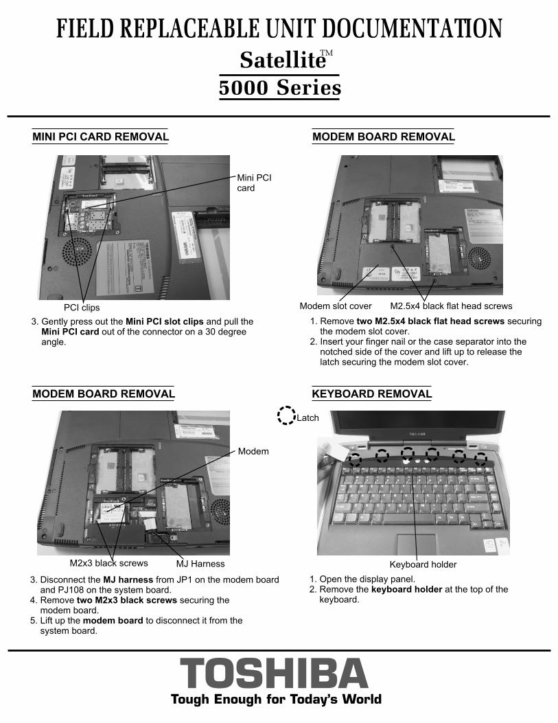
MODEM BOARD REMOVAL
MODEM BOARD REMOVAL
MINI PCI CARD REMOVAL
1. Remove two M2.5x4 black flat head screws securing the modem slot cover.2. Insert your finger nail or the case separator into the notched side of the cover and lift up to release the latch securing the modem slot cover.
TOSHIBATough Enough for Today’s World
1. Open the display panel.2. Remove the keyboard holder at the top of the keyboard.
KEYBOARD REMOVAL
FIELD REPLACEABLE UNIT DOCUMENTATION
5000 Series
Modem slot cover M2.5x4 black flat head screws
3. Gently press out the Mini PCI slot clips and pull the Mini PCI card out of the connector on a 30 degree angle.
Mini PCI card
PCI clips
3. Disconnect the MJ harness from JP1 on the modem board and PJ108 on the system board.4. Remove two M2x3 black screws securing the modem board.5. Lift up the modem board to disconnect it from the system board.
M2x3 black screws
Modem
MJ Harness
Latch
Keyboard holder
SatelliteTM
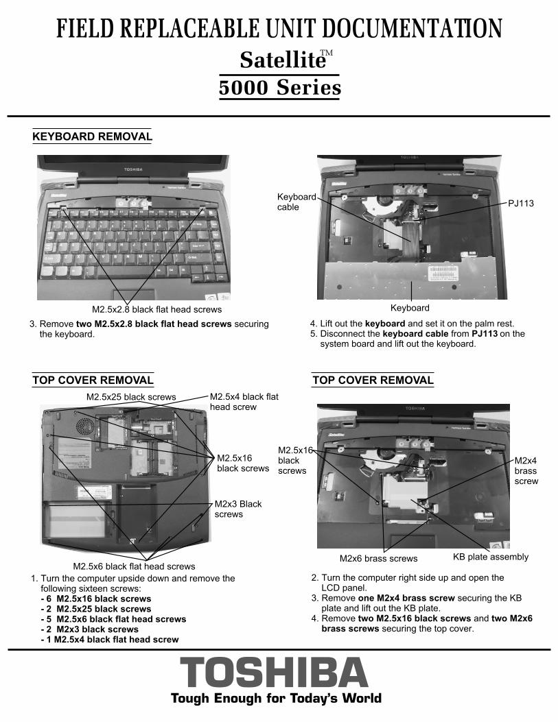
2. Turn the computer right side up and open the LCD panel.3. Remove one M2x4 brass screw securing the KB plate and lift out the KB plate.4. Remove two M2.5x16 black screws and two M2x6 brass screws securing the top cover.
4. Lift out the keyboard and set it on the palm rest.5. Disconnect the keyboard cable from PJ113 on the system board and lift out the keyboard.
KEYBOARD REMOVAL
TOP COVER REMOVAL
FIELD REPLACEABLE UNIT DOCUMENTATION
5000 Series
TOSHIBATough Enough for Today’s World
3. Remove two M2.5x2.8 black flat head screws securing the keyboard.
M2.5x2.8 black flat head screws
PJ113Keyboardcable
Keyboard
TOP COVER REMOVAL
1. Turn the computer upside down and remove the following sixteen screws: - 6 M2.5x16 black screws - 2 M2.5x25 black screws - 5 M2.5x6 black flat head screws - 2 M2x3 black screws - 1 M2.5x4 black flat head screw
M2.5x25 black screws
M2.5x16black screws
M2x3 Blackscrews
M2.5x6 black flat head screwsKB plate assembly
M2x4 brass screw
M2.5x4 black flathead screw
M2x6 brass screws
M2.5x16black screws
SatelliteTM
TOSHIBATough Enough for Today’s World
TOP COVER REMOVAL CD-R/W/DVD-ROM DRIVE REMOVAL
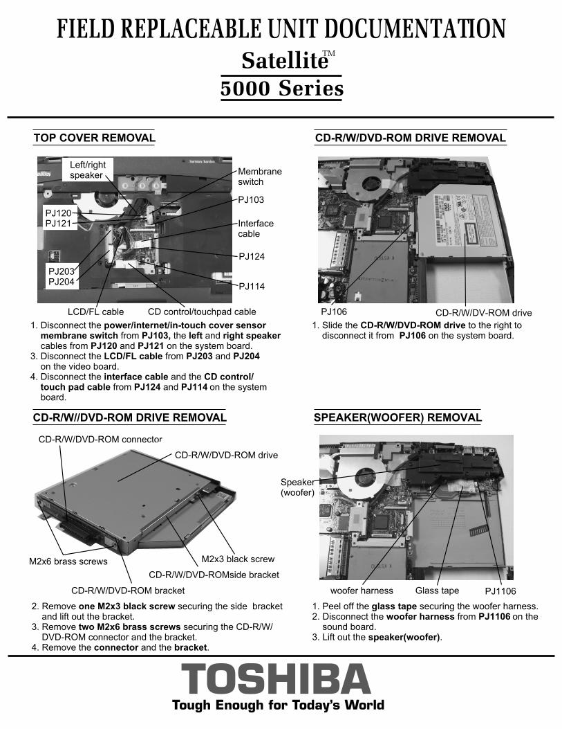
1. Slide the CD-R/W/DVD-ROM drive to the right to disconnect it from PJ106 on the system board.
FIELD REPLACEABLE UNIT DOCUMENTATION
5000 Series
CD-R/W//DVD-ROM DRIVE REMOVAL
M2x6 brass screws M2x3 black screw
CD-R/W/DVD-ROMside bracket
CD-R/W/DVD-ROM bracket
CD-R/W/DVD-ROM connector
CD-R/W/DVD-ROM drive
SPEAKER(WOOFER) REMOVAL
2. Remove one M2x3 black screw securing the side bracket and lift out the bracket.3. Remove two M2x6 brass screws securing the CD-R/W/ DVD-ROM connector and the bracket.4. Remove the connector and the bracket.
1. Peel off the glass tape securing the woofer harness.2. Disconnect the woofer harness from PJ1106 on the sound board.3. Lift out the speaker(woofer).
woofer harness Glass tape
Speaker(woofer)
PJ1106
PJ106 CD-R/W/DV-ROM drive
1. Disconnect the power/internet/in-touch cover sensor membrane switch from PJ103, the left and right speaker cables from PJ120 and PJ121 on the system board.3. Disconnect the LCD/FL cable from PJ203 and PJ204 on the video board.4. Disconnect the interface cable and the CD control/ touch pad cable from PJ124 and PJ114 on the system board.
Membraneswitch
PJ103
Left/rightspeaker
Interface cable
CD control/touchpad cableLCD/FL cable
PJ203PJ204
PJ124
PJ114
PJ120PJ121
SatelliteTM
TOSHIBATough Enough for Today’s World
SOUND BOARD REMOVAL
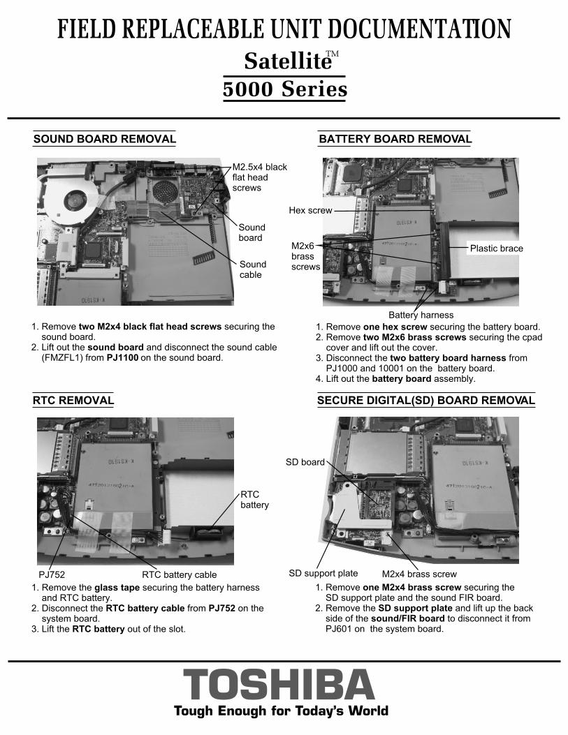
1. Remove two M2x4 black flat head screws securing the sound board.2. Lift out the sound board and disconnect the sound cable (FMZFL1) from PJ1100 on the sound board.
SECURE DIGITAL(SD) BOARD REMOVAL
FIELD REPLACEABLE UNIT DOCUMENTATION
5000 Series
1. Remove one M2x4 brass screw securing the SD support plate and the sound FIR board.2. Remove the SD support plate and lift up the back side of the sound/FIR board to disconnect it from PJ601 on the system board.
M2.5x4 blackflat head screws
Sound board
Sound cable
BATTERY BOARD REMOVAL
1. Remove one hex screw securing the battery board.2. Remove two M2x6 brass screws securing the cpad cover and lift out the cover.3. Disconnect the two battery board harness from PJ1000 and 10001 on the battery board.4. Lift out the battery board assembly.
RTC REMOVAL
1. Remove the glass tape securing the battery harness and RTC battery.2. Disconnect the RTC battery cable from PJ752 on the system board.3. Lift the RTC battery out of the slot.
M2x6brassscrews
Battery harness
Plastic brace
RTCbattery
PJ752 RTC battery cable M2x4 brass screwSD support plate
SD board
Hex screw
SatelliteTM
CPU REMOVAL
COOLING MODULE REMOVAL
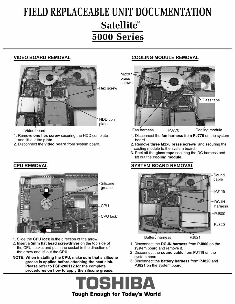
1. Disconnect the fan harness from PJ770 on the system board. 2. Remove three M2x8 brass screws and securing the cooling module to the system board.3. Peel off the glass tape securing the DC harness and lift out the cooling module.
Fan harness Cooling module
M2x8brass screws
PJ770
FIELD REPLACEABLE UNIT DOCUMENTATION
5000 Series
TOSHIBATough Enough for Today’s World
1. Slide the CPU lock in the direction of the arrow.2. Insert a 5mm flat head screwdriver on the top side of the CPU socket and push the socket in the direction of the arrow and lift out the CPU.
NOTE: When installing the CPU, make sure that a silicone grease is applied before attaching the heat sink. Please refer to FSB-200112 for the complete procedures on how to apply the silicone grease.
Glass tape
VIDEO BOARD REMOVAL
1. Remove one hex screw securing the HDD con plate and lift out the plate.2. Disconnect the video board from system board.
HDD conplate
Video board
Hex screw
SYSTEM BOARD REMOVAL
1. Disconnect the DC-IN harness from PJ800 on the system board and remove it.2. Disconnect the sound cable from PJ119 on the system board.3. Disconnect the battery harness from PJ820 and PJ821 on the system board.
DC-INharness
PJ800
Battery harness
PJ820
PJ821
Sound cable
PJ119
1
2
SatelliteTM
CPU lock
CPU
Siliconegrease
TOSHIBATough Enough for Today’s World
FIELD REPLACEABLE UNIT DOCUMENTATION
5000 Series
INTERFACE BOARD REMOVAL
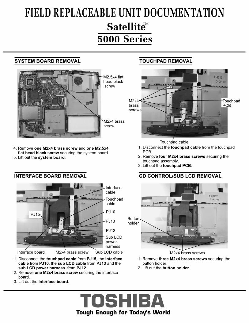
4. Remove one M2x4 brass screw and one M2.5x4 flat head black screw securing the system board. 5. Lift out the system board.
M2x4 brassscrew
M2.5x4 flat head black screw
SYSTEM BOARD REMOVAL TOUCHPAD REMOVAL
1. Disconnect the touchpad cable from the touchpad PCB.2. Remove four M2x4 brass screws securing the touchpad assembly.3. Lift out the touchpad PCB.
TouchpadPCB
Touchpad cable
M2x4brassscrews
1. Disconnect the touchpad cable from PJ15, the interface cable from PJ10, the sub LCD cable from PJ13 and the sub LCD power harness from PJ12. 2. Remove one M2x4 brass screw securing the interface board.3. Lift out the interface board.
Interfacecable
Touchpad cable
Sub LCDpowerharness
Sub LCD cableM2x4 brass screwInterface board
CD CONTROL/SUB LCD REMOVAL
1. Remove three M2x4 brass screws securing the button holder.2. Lift out the button holder.
M2x4 brass screws
Buttonholder
SatelliteTM
PJ10
PJ13
PJ12
PJ15
FIELD REPLACEABLE UNIT DOCUMENTATION
5000 Series
TOSHIBATough Enough for Today’s World
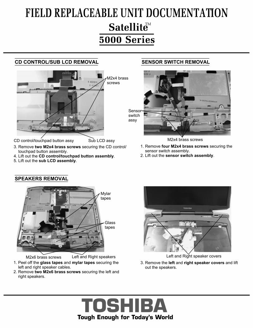
3. Remove two M2x4 brass screws securing the CD control/ touchpad button assembly. 4. Lift out the CD control/touchpad button assembly. 5. Lift out the sub LCD assembly.
CD CONTROL/SUB LCD REMOVAL SENSOR SWITCH REMOVAL
1. Remove four M2x4 brass screws securing the sensor switch assembly.2. Lift out the sensor switch assembly.
M2x4 brass screws
Sensorswitchassy
SPEAKERS REMOVAL
1. Peel off the glass tapes and mylar tapes securing the left and right speaker cables. 2. Remove two M2x6 brass screws securing the left and right speakers.
3. Remove the left and right speaker covers and lift out the speakers.
Mylartapes
Glasstapes
SatelliteTM
M2x4 brassscrews
CD control/touchpad button assy Sub LCD assy
Left and Right speaker coversLeft and Right speakersM2x6 brass screws
FL INVERTER AND 15” LCD REMOVAL
FIELD REPLACEABLE UNIT DOCUMENTATION Satellite
TM
5000 Series
TOSHIBATough Enough for Today’s World
15” DISPLAY MASK REMOVAL
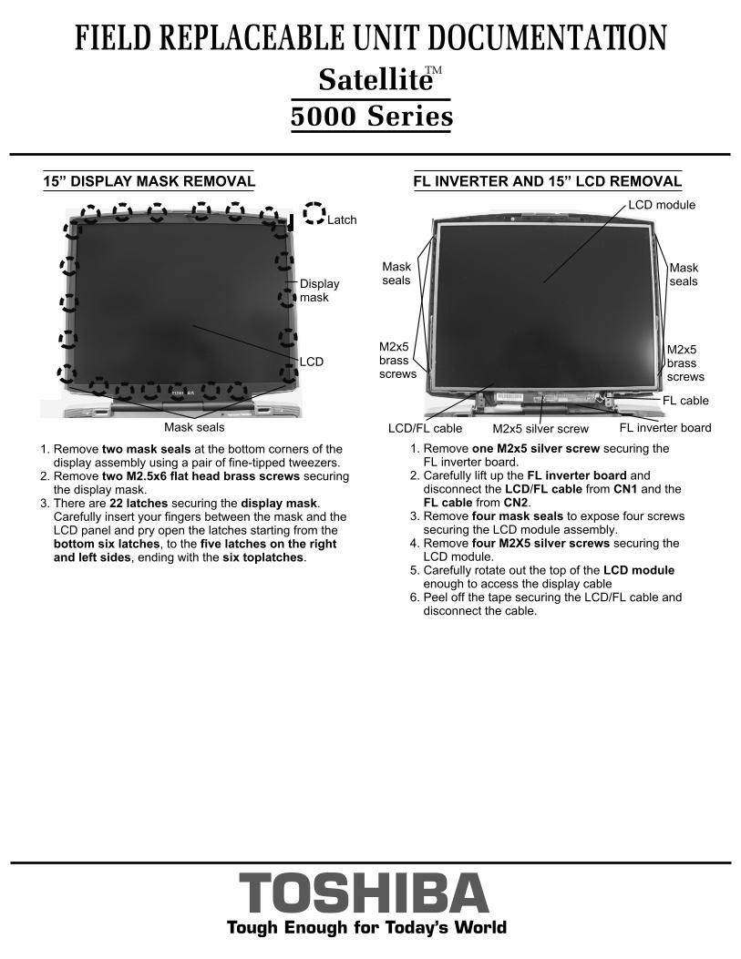
1. Remove two mask seals at the bottom corners of the display assembly using a pair of fine-tipped tweezers.2. Remove two M2.5x6 flat head brass screws securing the display mask.3. There are 22 latches securing the display mask. Carefully insert your fingers between the mask and the LCD panel and pry open the latches starting from the bottom six latches, to the five latches on the right and left sides, ending with the six toplatches.
Latch
Mask seals
Displaymask
LCD
LCD module
M2x5 silver screw FL inverter board
M2x5brassscrews
M2x5 brassscrews
Maskseals
Maskseals
LCD/FL cable
FL cable
1. Remove one M2x5 silver screw securing the FL inverter board.2. Carefully lift up the FL inverter board and disconnect the LCD/FL cable from CN1 and the FL cable from CN2.3. Remove four mask seals to expose four screws securing the LCD module assembly.4. Remove four M2X5 silver screws securing the LCD module.5. Carefully rotate out the top of the LCD module enough to access the display cable6. Peel off the tape securing the LCD/FL cable and disconnect the cable.