Embed Size (px)
Citation preview
0.00
-18.30
Tie in
Com
pres
sion
Tie in
Ten
sion
Bending momentswithout ties
Bending momentswith ties
Mt Wind loads
RxMw
20.90m
18.90m
Why prestressedconcrete cable? As protection
for fire
To decreaseshrinkage stresses
42 cm
42 cm
5,9 m
Slab
Slab
Steel plate 5 mm
Cables
Pase
o de
la C
aste
llana
Pase
o de
Rec
olet
os
Plaza deColón
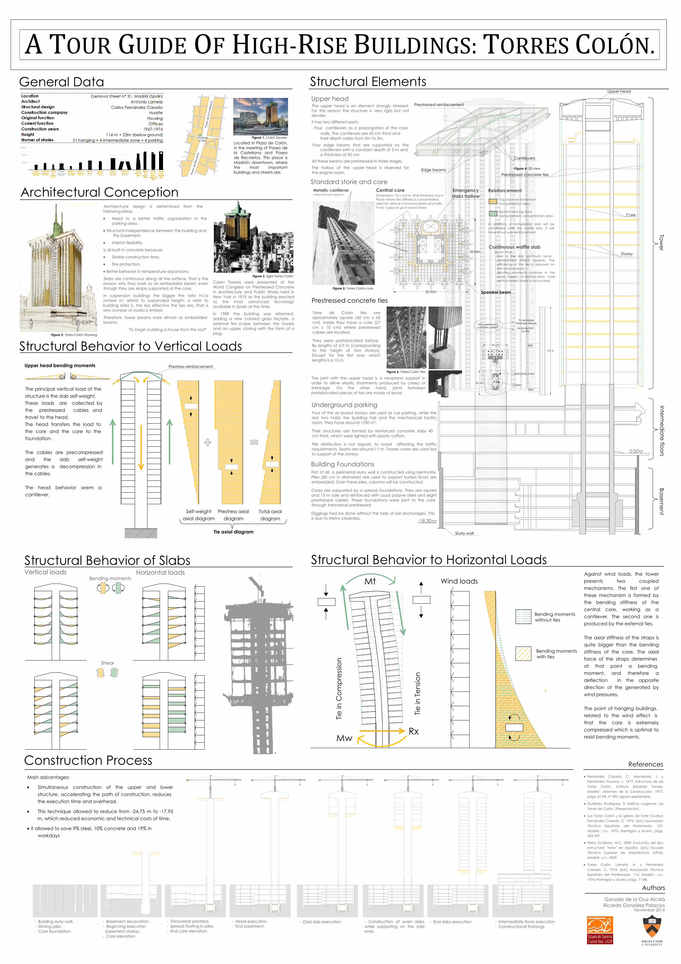
The principal vertical load of the structure is the slab self-weight. These loads are collected by the prestressed cables and travel to the head.The head transfers the load to the core and the core to the foundation.
The cables are precompressed and the slab self-weight generates a decompression in the cables.
The head behavior seem acantilever.
Upper headThe upper head is an element strongly stressed. For this reason the structure is very rigid but not slender.It has two different parts:- Four cantilevers as a prolongation of the core
walls. The cantilevers are 60 cm thick and their depth varies from 5m to 3m.
-Four edge beams that are supported by thecantilevers with a constant depth of 3 m anda thickness of 50 cm.
All these beams are prestressed in three stages.The hollow of the upper head is reserved for the engine room.
- Basement excavation.- Beginning execution
basement storeys. - Core elevation
- Building slurry wall.- Driving piles.- Core foundation.
- Transversal prestress.- Spread footing in piles.- End core elevation.
- Head execution.- End basement.
- Odd slab execution - Construction of even slabswhile supporting on the oddones.
- End slabs execution - Intermediate floors execution- Constructional finishings
Continuous waffle slab- 25 cm thick- Due to the slab continuity some
embedment effects appears. The efficiency of the ties is reduced on the lower storeyes
- Bending moments increase in thelower beams. At that location, more reinforcement need to be located
Reinforcement
Top face reinforcement concentration area
Bottom and top face reinforcement concentration area
In addition, a compression slab will be constituted over the waffle slab. It will have a two way reinforcement.
Metallic cantileverwhere the slab supports
Central coreDimensions: 7m x 6,8 m; Wall thickness: 0,6 m Place where the stiffness is concentrated.Used for vertical communications and halls. It has 7 gaps to go in every storey
Emergencystairs hollow
Spandrel beam
Torre de Colon ties are aproximately square (42 cm x 42 cm). Inside they have a core (27 cm x 10 cm) where prestressed cables are located.
They were prefabricated before. By lengths of 5,9 m (corresponding to the heigth of two storeys). Except for the first one, which lengths is 6,15 m.
Underground parkingFour of the six buried storeys are used as car parking, while the rest two holds the building hall and the mechanicall facility room. They have around 1700 m2.
Their structures are formed by reinforced concrete slabs 40 cm thick, which were lighted with plastic coffers.
Pile distribution is not regular, to avoid affecting the traffic requirements. Spans are around 11 m. Towers cores are used too to support of the storeys.
Building FoundationsFirst of all, a perimetral slurry wall is constructed using bentonite. Piles (60 cm in diameter) are used to support buried floors are embedded. Over these piles, columns will be constructed.
Cores are supported by a spread foundations. They are square and 13 m side and reinforced with usual passive steel and eight prestressed cables. These foundations were joint to the core through transversal prestressed.
Diggings had be done without the help of soil anchorages. Thisis due to Metro closeness.
Prestressed concrete ties
Standard storie and core
Edge beams
Cantilevers
Prestressed reinforcement
Figure 4. 3D view
Prestressed concrete ties
Core
Storey
Upper head
The joint with the upper head is a neoprene support in order to allow elastic shortments produced by creep or shrinkage. On the other hand, joints between prefabricated pieces of ties are made of epoxi.
Tower
Intermed
iate floorsBasem
ent
Slurry wall
Against wind loads, the tower presents two coupled mechanisms. The first one of these mechanism is formed by the bending stiffness of the central core, working as a cantilever. The second one is produced by the external ties.
The axial stiffness of the straps is quite bigger than the bending stiffness of the core. The axial force of the straps determines at that point a bending moment, and therefore a deflection in the opposite direction of the generated by wind pressures.
The point of hanging buildings, related to the wind effect, is that the core is extremely compressed which is optimal to resist bending moments.
Self-weightaxial diagram
Prestress axialdiagram
Total axialdiagram
Tie axial diagram
Structural Elements
Located in Plaza de Colón,in the meeting of Paseo dela Castellana and Paseode Recoletos. This place isMadrid's downtown, wherethe most importantbuildings and streets are.
Figure 1. Colón Square.
Structural Behavior to Horizontal Loads
Structural Behavior to Vertical Loads
Construction Process
Structural Behavior of SlabsVertical loads Horizontal loads
Upper head bending moments Prestress reinforcement
Architectural design is determined from the following ideas:
Need to a better traffic organization in theparking area.
Structural independence between the building and the basement.
Interior flexibility.
Is all built in concrete because:
Similar construction time.
Fire protection.
Better behavior in temperature expansions.
Slabs are continuous along all the surface. That is the reason why they work as an embeddeb beam, even though they are simply supported at the core.
In suspension buildings the bigger the ratio h1/a (where h1 referst to suspended heigth; a refer to building side) is, the less effective the ties are. That is why number of stories is limited.
Therefore, lower beams work almost as embeddedbeams.
"To begin building a house from the roof"
Architectural Conception
General Data
Colon Towers were presented at theWorld Congress on Prestressed Concretein Architecture and Public Works held inNew York in 1975 as the building erectedas the most advanced tecnologyavailable in Spain at the time.
In 1989 the building was reformed,adding a new colored grass façade, aexternal fire scape between the towersand an upper closing with the form of aplug.
Shear
Bending moments
Fernández Casado, C., Manterola, J. yFernández Troyano, L. 1977. Estructura de lasTorres Colón. Instituto Eduardo Torroja.Madrid : Informes de la Construcción, 1977.págs. 61-94. nº 293 agosto-septiembre.
Gutiérrez Rodríguez, E. Edificio colgante: lasTorres de Colón. [Presentación]
Las Torres Colón y la iglesia de Torre Ciudad.Fernández Casado, C. 1973. [ed.] AsociaciónTécnica Española del Pretensado. 107,Madrid : s.n., 1973, Hormigón y Acero, págs.343-347.
Pérez Gutiérrez, M.C. 2009. Evolución del tipoestructural "torre" en España. [ed.] EscuelaTécnica Superior de Arquitectura (UPM).Madrid : s.n., 2009.
Torres Colón. Lamela, A. y FernándezCasado, C. 1974. [ed.] Asociación TécnicaEspañola del Pretensado. 112, Madrid : s.n.,1974, Hormigón y Acero, págs. 71-88.
References
Authors
Gonzalo de la Cruz AlcaláRicardo González Palacios
November 2014
A TOUR GUIDE OF HIGH-RISE BUILDINGS: TORRES COLÓN.
Main advantages:
Simultaneous construction of the upper and lowerstructure, accelerating the path of construction, reduces the execution time and overhead.
This technique allowed to reduce from -24.75 m to -17.95m, which reduced economic and technical costs of time.
It allowed to save 9% steel, 10% concrete and 19% inworkdays
Figure 2. Torres Colón Drawing
Figure 3. Sight Torres Colón
Figure 5. Torres Colón core.
Figure 6. Torres Colón Ties