Embed Size (px)
Citation preview

VEL–BFVM– 2002
TORQSEAL VALVESMAINTENANCE MANUAL, Triple Offset, Metal-Seated Butterfly Valve3–36”, (80–900 mm)
MaintenanceManuals

2
I INTRODUCTION ........................................................................................................................4
1.1 General Introduction ..............................................................................................................................4
1.2 Types of Butterfly Valves ......................................................................................................................5
1.3 Essential Features of Velan Valves........................................................................................................6
II RECEIVING AND PREPARATION FOR INSTALLATION ........................................................................7
2.1 Receiving Inspection ..............................................................................................................................7
2.2 Quality Control Documentation ............................................................................................................7
2.3 Storage ....................................................................................................................................................7
2.4 Handling and Preparation ......................................................................................................................7
2.5 Special Instructions for Butterfly Valves ..............................................................................................7
2.5.1 Inspection ....................................................................................................................................7
2.5.2 Installation ....................................................................................................................................7
2.5.2.1 Double Flanged: Long and Short Pattern ....................................................................8
2.5.2.2 Wafer Type ......................................................................................................................8
2.5.2.3 Lug Type ..........................................................................................................................8
2.5.3 Valve Verification ........................................................................................................................8
III WARNINGS ............................................................................................................................9
IV GENERAL MAINTENANCE ........................................................................................................10
4.1 Operation ..............................................................................................................................................10
4.1.1 General ......................................................................................................................................10
4.1.2 Number of Packing Rings..........................................................................................................10
4.1.3 Seat Tightness / Closing Torques ............................................................................................11
4.1.4 Smoothness of Operation ........................................................................................................11
4.1.5 Closing Torques VS. Differential Pressure for “0” Leakage ..................................................12
4.2 General Assembly Information ..........................................................................................................13
4.2.1 Butterfly Valve Assembly Drawing ..........................................................................................14
4.3 General Fasteners / Max Torque Values ............................................................................................14
V DETAILED MAINTENANCE........................................................................................................15
5.1 Trouble Shooting Chart........................................................................................................................15
5.2 Seat Leakage ........................................................................................................................................16
5.3 Packing Chamber Leakage ..................................................................................................................16
5.4 Retaining Ring Fasteners ....................................................................................................................17
TABLE OF CONTENTS

3
VI MAINTENANCE PROCEDURE ....................................................................................................18
6.1 Butterfly Valve Exploded View ............................................................................................................18
6.2 Partial Disassembly ..............................................................................................................................20
6.2.1 Laminated Seal & Spiral Wound Gasket Replacement ..........................................................20
6.2.2 Packing Ring Replacement........................................................................................................22
6.3 Total Disassembly of Butterfly Valve ..................................................................................................25
6.3.1 General ......................................................................................................................................25
6.3.2 Complete Disassembly..............................................................................................................25
6.3.3 Detailed Maintenance (after total disassembly)......................................................................26
6.4 Complete Assembly ............................................................................................................................27
VII APPENDIX ........................................................................................................................29
7.1 Procedure for Removing Manual Gear Actuator ..............................................................................29
7.2 Procedure for Removing Motor Actuators ........................................................................................29
7.3 Procedure for Removing Motor, Hydraulic or Pneumatic Actuators ..............................................29
7.4 Spare Parts ............................................................................................................................................30
TERMS AND CONDITIONS OF SALE ..................................................................................................................31
LIST OF TABLES
Table 1 - Recommended Lubrication ..........................................................................................................11
Table 2 - Torque Values - General Fasteners ft•lbs (Nm) ..........................................................................14
Table 3 - Troubleshooting ............................................................................................................................15
Table 4 - Torque Values for Gland Nuts ....................................................................................................16
Table 5 - Torque Values for Retaining Ring Fasteners..............................................................................17
Table 6 - Bill of Materials ..............................................................................................................................19
LIST OF PROCEDURES
Procedure 1 - Laminated Seal and Gasket replacement ............................................................................20
Procedure 2 - Packing Replacement ............................................................................................................22
Procedure 3 - Complete Disassembly..........................................................................................................25
Procedure 4 - Complete Assembly ............................................................................................................27
TABLE OF CONTENTS

4
I INTRODUCTION
This manual has been prepared by VELAN engi-
neers, designers, R & D and technical personnel
to assist you in obtaining many years of satisfac-
tory service from your Butterfly Valves. It will assist
you in restoring your valve to best working condition
with minimum of time and expense.
VELAN Valves are designed and manufactured based
on many years of research and product development
and are constantly being improved. Before beginning
any major works, we recommend that you read this
booklet carefully at least once to understand the
valve's physical condition.
Please note that if you do not understand the reason
for the service problem, we suggest that you get in
touch with your local VELAN representative or call the
Field Engineering Service Manager for technical assis-
tance. 514-748-7743-ext.2226.
Before beginning any major work, we recommend
that you carefully check the nameplate of the valve
and record the figure number and the tag number to
identify the type and size of valve. See the “Essential
Features of VELAN valves” (Section 1.3) for an expla-
nation of VELAN “Figure Numbers.”
1.1 GENERAL INTRODUCTION

I INTRODUCTION
4
Figure 1.2 Four Basic Body Styles
1.2 TYPES OF BUTTERFLY VALVES
Velan butterfly valves cover a range of sizes andpressure classes. Each of them is built in Fourbasic body styles:
1. Lug/Single Flange2. Wafer Type 3. Double Flanged “Short Pattern”4. Double Flanged “Long Pattern”
• Double Flanged type which can be installedbetween two flanges using gaskets and fasteners.
• Wafer Type which can be installed between twoflanges.
• Lug/Single Flange which can be installedbetween two flanges and or bolted to eitherflange.
For stem sealing options see section 5.1
LUG TYPE WAFER TYPE
SHORT PATTERN LONG PATTERN

6
Metal-Seated Triple Offset Butterfly Valves
TYPE OF CONNECTION
A – Special C – Combination L – Lug R – Flanged, ring joint W – WaferB – Butt weld F – Flanged, B16.5 (MSS > 24”) P – Flanged, API 605 > 24” U – Undrilled flanges
*SIZE OF CONNECTION
Customers have the choice of specifying valve size as part of the valve figure number (“B”) using the numbers below, or indicating valve size separately.
EXAMPLES: F14-1BA02-DABA (valve size is part of figure number)3” F-1BA02-DABA (valve size is shown separately)
10 –3” (80 mm) 14 –6” (150 mm) 19 –14” (350 mm) 24 – 24” (600 mm) 32 – 32” (800 mm)11 –31⁄2” (90 mm) 15 –8” (200 mm) 20 –16” (400 mm) 26 – 26” (650 mm) 34 – 34” (850 mm)12 –4” (100 mm) 16 –10” (250 mm) 21 –18” (450 mm) 28 – 28” (700 mm) 36 – 36” (900 mm)13 –5” (125 mm) 18 –12” (300 mm) 22 – 20” (500 mm) 30 – 30” (750 mm) 99 – Special
PRESSURE RATING
0– 1501– 300
VALVE TYPE
A – Metal seat seal in disc (API 609 Long Pat.) ASME B16.10B – Metal seat seal in disc (API 609 Short Pat.) ISO 5752C – Metal seat seal in disc lug, wafer
SEAL RING
A – SS 316 + Grafoil C – Monel + Grafoil E – Inconel + Grafoil G – SS 316 (solid) J – Alloy 20 (solid) L – Xm19, (Nitronic 50) Z – SpecialB – SS 410 + Grafoil D – Alloy 20 + Grafoil F – Hastelloy + Grafoil H – Monel (solid) K – Inconel (solid) P – Duplex SS + Grafoil
BODY MATERIAL
01 – Special 04 – Chr. moly, F5, C5 09 – Chr. moly, F9, C12 19 – Monel 22 – Titanium 32 - Stainless steel F5102 – A105, WCB 05 – Chr. moly, F11, WC6 10 – Stainless steel F316H 20 – Inconel C 23 – Alloy 20 34 - F9103 – Carbon moly, F1, WC1 06 – Chr. moly, F22, WC9 13 – Stainless steel F316, CF8M 21 – Hastelloy Gr.5 31 - LCC 37 - Incoloy
BEARING MATERIAL
A – SS 316 Nitrided D – SS Chrome plated G – HastelloyB – XM19, (Nitronic 50) E – Monel H – Alloy 20C – CS Nitrided F – Inconel J – Stellite
DISC
A – Same as body plated C – SS 316, CF8M F – Inconel H – Alloy 20B – Same as body not plated E – Monel G – Hastelloy Z – Special
SHAFT
A – SS 410 D – SS 630 G – Hastelloy J – SS 660B – SS 316 E – Monel H – Alloy 20C – XM19, (Nitronic 50) F – Inconel Z – Special
SPECIAL SERVICE
A – Standard F – LNG H – Cryogenic service J – Vacuum service P – Powders X – SpecialC – Chlorine service G – Oxygen service I – NACE N – Nuclear R – Coker
1.3 ESSENTIAL FEATURES OF VELAN VALVES
A
B
D
E
F
G
H
I
J
C
I INTRODUCTION
SIZE OFCONNECTION*
VALVETYPE
BODYMATERIAL
BEARINGMATERIAL
SEAT/SEALMATERIAL
A B C D E
DISCMATERIAL
HF G
TYPE OFCONNECTION
F 1 4 — 1 B A O 2 — D C A A
EXAMPLE: Flanged, 6”, Class 300, metal seal in disc, short pattern, carbon steel with stainless steel trim.
SHAFTMATERIAL
I
SPECIALSERVICE OR
DESIGN
J
— —
PRESSURERATING

7
2.1 RECEIVING INSPECTIONAll valves must be examined for signs of damagethat may have occurred during handling and trans-portation. Any damage should be analyzed and areport should be issued. Serious damage shouldbe reported to your local Velan representative or toThe Customer Service Manager and also to theTransport Carrier so that a suitable arrangementfor repairs can be made without delay.
2.2 QUALITY CONTROL DOCUMENTATIONFor valves purchased with Quality Control (QC)certification, documents must verify the package ofdocuments to see that the Quality Control docu-ments are completed as per the purchase order.
2.3 STORAGEValve should be stored in a suitable shelteredplace to prevent contamination by weather, dirt ordampness. The valve is shipped with end protec-tors on the inlet and outlet which should remain onthe valve until it is ready for installation.
NOTE: If actuators are involved, please referto the applicable manufacturer's instructionsfor storage.
2.4 HANDLING AND PREPARATIONOn large valves, a hoist is needed to assist installa-tion. A nylon sling should be placed under thevalve body so that the unit can be lifted verticallyto its final destination. Ends protectors must beremoved from all types of valves prior to installa-tion and connections must be checked for cleanli-ness. Any visible foreign matter must be removedfrom end connections of the valve. The flangesmust be cleaned properly with suitable solventsuch as acetone or alcohol. Do not use solventscontaining chloride or fluoride.
2.5 SPECIAL INSTRUCTIONS FOR BUTTERFLY VALVES
2.5.1 InspectionCarefully remove the valve from the shipping pack-age (box or pallet) to avoid any damage to thevalve and components or, in the case of automat-ed valves to the electric, pneumatic/hydraulic actu-ator or instrumentation.
Prior to installation, clean the inside of the valve.Ensure that there are no solid objects such as bitsof wood, plastic or packaging materials within thevalve or on the valve seat.
Inspect the seal ring to ensure that it was not dam-aged during transportation and handling. This isespecially important in the event of valves with“fail-open” actuators.
Verify that the materials of construction listed onthe valve nameplate are appropriate for the ser-vice intended and are as specified.
Locate the “HP” marking on the body whichdefines the preferred mounting orientation inrespect to the pressure. In most cases the valve isproperly installed when the actuator fluid flow orhigh pressure is acting on the shaft side of the discwhen the valve is closed.
Ensure that the packing flange bolting nuts againstthe packing flange cannot be rotated by hand.
2.5.2 InstallationVelan recommends that all common safety prac-tices be followed during installation of the valveinto the line.
Recommended installation orientation is withvalve shaft horizontal or inclined from vertical.This will minimize any problems associated withsolid particles present in the process that other-wise could deposit in the lower bearing.
Unless recommended otherwise by VELAN, mountthe valve in preferred direction, with the “HP”marking pointing to the lower pressure side sothat the shaft side of the disc will be upstreamwhen the valve is in closed position.
WARNING: The use of impact wrench toinstall & assemble Velan Valve is not permit-ted. Use of such tool can cause valve bodyseat to deform, and the change in shape mayresult in leaks or internal bleeding.
For operating temperatures above 392ºF (200ºC)thermal insulation of body is recommended.
The depth of the tapped holes in the bodies of allwafer valves is specified in the technical literaturesupplied with the valve. Failure to use correct (size& grade) cap screws/studs may result in damageto the valve.
The valve should be installed in the closed posi-tion to ensure that the laminated seal in the disc isnot damaged during installation.
Particular care should be taken with those valvesequipped with “fail-open” actuators.
If the pipe is lined, confirm that the disc does notcontact the lining during the opening stroke, espe-cially in wafer and short pattern body styles. Failureto confirm that the disc rotation does not contactthe lining may result in damage to the valve.
RECEIVING AND PREPARATION FOR INSTALLATION II

8
2.5.2.1. Double Flanged: Long and Short PatternOrient the valve with the “HP“ marking (preferredside) in the proper position.
Insert the valve between the two flanges until thetwo bottom holes in the valve body align with thetwo lower flange holes. Or, as an alternative, insertstuds of one half to two times the correct length inthe lowest four flange holes. This will allow thevalve to rest loosely for the installation of theflange gasket.
Install the flange gasket and remaining flangebolts/studs along with anti-seize compound on thethreads.
Using the bolt tightening sequence cross overmethod, tighten all nuts.
NOTE: Cap screws will be necessary for thetop and bottom alignment tapped holes. Thestuds should be used in the through-holes.
2.5.2.2 Wafer TypeOrient the valve with the “HP“ marking (preferredside) in the proper position.
Insert the valve between the two pipe flanges untilthe alignment holes at either side of the valvematch and align the corresponding holes in theflanges (assuming horizontal position). Do not usethe valve to align mis-aligned piping.
Insert a long cap screw or stud through the flangeand thread it into the body/flange. This will allowthe valve to center and align itself properly for theinstallation of the flange gasket.
Install the flange gasket and the remaining flangecap screws/studs/nuts etc.
Remove the long cap screws/studs from the loweralignment holes and replace with the correct fas-teners.
Using the cap screw tightening sequence, tightenall flange screws, incrementally. Maintaining uni-form clearance around studs and flange holes.
Seat the flanges by tightening the flanges capscrews/studs, little at a time until flanges face seats.During this operation it is recommended to continu-ously check the distance between the flange facesand select the tightening sequence to maintain theparallelism of the both mating flanges.
Complete the final torquing of the flanges in 3 to 4increments to the recommended torque valve.
2.5.2.3 Lug TypeOrient the valve with the “HP“ marking (preferredside) in the proper position.
Insert the valve between the two flanges until thetwo bottom holes of the valve align with the twolower flange holes.
Insert cap screw or stud through the flange andscrew it into valve body holes. This will allow thevalve to center and align properly for the installa-tion of the flange gasket. The connecting flangeface may not be more than 1/4” away from thevalve flange face. Do not use the valve to alignmis-aligned piping.
Install the flange gasket and the remaining flangecap screws.
Use Anti-seize compound around fastener threads.
Remove the two extra long cap screws/studs fromthe lower alignment holes and replace them withcorrect sized cap screws/studs.
Tighten all flange cap screws/studs as per tighten-ing sequence in 3 to 4 increments, to the recom-mended torque.
2.5.3 Valve VerificationTightening the packing flange as per torque tableto prevent stem leakage. Over-tightening willdecrease packing life and increase operatingtorque (rim pull) requirements.
Check the operation of the valve by stroking to“100% open” to “100% close”. To determine theorientation of the disc, the index marking on theshaft is aligned with the corresponding markingon the body in the closed position.
The valve disc travels clockwise to close/counterclockwise to open.
For automated valves, set the air pressure/electri-cal voltage for at least the minimum given toselect the actuator. For pneumatic actuators, donot apply more than 1.25 times the pressure forwhich the actuator was designed. (Work with thesizing sheet from engineering).
NOTE: For springs return actuators with posi-tioners, overpressure will cause excessivetime delay in obtaining a spring movement forthe valve disc to open or close.
The use of impact wrenches to install a Velanvalve is not permitted, use of the impact wrenchescan cause body seat to change the geometry ofvalve body and internal component (shape),increasing the possibility of valve leakage or inter-nal grinding.
II RECEIVING AND PREPARATION FOR INSTALLATION

9
FOR SAFETY REASONS,it is important to take these precautions
before removing a valve from a line.
☛ Personnel making adjustments to the valves shouldwear safety equipment normally used to work with fluidin the lines where the valve is installed.
☛ Before removing a valve from a line, line pressure mustbe relieved with no exception. Failure to do so maycause serious personal injury and/or equipment damage.
☛ Velan valves can be equipped with a variety of manualgear, electric, hydraulic or pneumatic actuators.Generally, all pressure must be relieved from both sidesof the valve (inlet & outlet) before the actuators areremoved/disassembled.
☛ The packing rings must be replaced under no pressure.Removal of the packing with the valve under pressureis at the owner's risk.
Warning on NACE Conversions
It is extremely important to ensure that valves, when convertedto NACE trims in the field are done by Velan authorized serviceshops. Unauthorized conversions can result in failure to carryout post-weld heat treatment and result in severe stress cracksin non-stress relieved areas.
SAFETY WARNINGS III
10
4.1 OPERATION
4.1.1 GeneralVelan butterfly valves have been designed to requirea minimum of maintenance; all valves require exam-ination before being put into service/operation.Additionally, valves should be inspected regularlyduring operation and should receive prompt atten-tion when troubles arise. As a general rule, valvesshould be subjected to scheduled maintenance.
Generally only maintenance on the packing box isrequired. If shaft leakage is observed through thepacking box, tighten the gland nuts to the torquetable.
NOTE: Do not over-tighten packing box glandnuts. Over-tightening will increase the torquerequired to operate the valve. When tighteningthe gland nuts, use half-turn increments untilleakage has stopped. Respect Torque Tablelimit. ±10%. Refer to Table 4.
4.1.2 Number of packing rings requiredAll Standard Velan Butterfly valves require five (5)packing rings. (during assembly verify with draw-ing) For valves equipped with a leak off connec-tion, and Lantern ring seven (7) are required. Four(4) packings are placed below the lantern ring andthree (3) above.
The following sketches show the four types ofpacking arrangements on Butterfly valves.
IV GENERAL MAINTENANCE
STANDARD LOW EMISSION STEM SEALWITH 0-20 PPM
Stem bearing
OPTIONAL LIVE-LOADING
EFV (ENVIRONMENTALLY FRIENDLY VALVE)STEM SEAL WITH “0” HELIUM BUBBLES
Braided GraphiteFEP TYP.
Graphite low density
Graphitehigh density
Figure 4.1.2A
Figure 4.1.2B

11
THE TA-LUFT SEAL WITH LESS THAN 1 PPM (0.0014 PPM)
GENERAL MAINTENANCE IV
LANTERN RING OPTION DOUBLE PACKEDWITH LEAK-OFF MONITORING PURGE PORT
4.1.3 Seat Tightness - Closing Torques
Even with a brand new valve, seat tightness willonly be achieved when sufficient load has beenapplied to the disc. This load varies with the pres-sure differential against which the valve has to beclosed or opened. Torque required to open or closea valve against a given differential pressure is givenin the following figure. The torque shown is thattorque which has to be applied directly to the Valvestem to achieve tight shut off and does not take intoaccount any mechanical advantage such as thatachieved with a gear actuator, cheater bar, etc.
CAUTION: The use of wheel wrenches,cheater bar, etc., is quite common. However,it must be emphasized that these devices
should be used with discretion, and only toachieve approximately the torque as shown inthe figure on the following page.
4.1.4 Smoothness of Operation
After complete disassembly of the valve some,internal moving components must be lubricatedwith recommended lubricants are shown in Table1. Valves that are not operated frequently andwhich may remain open or closed for longer peri-ods of time should be cycled (even if only partial-ly) about once every three months.
IMPORTANT: If excessive hand wheel effort isrequired refer to Troubleshooting chart inSection 5, Table 3.
Table 1: Recommended Lubrication
LUBRICATION PART FREQUENCY APPLICATIONGrease: CU 7439 Plus Molykote Bearing seals Thin layer in bearing seal groove
Anti-seize compound All bolts and studs except Seal At valve Thin layer on threadsretaining ring bolts (17B) assembly only
Dry lubricant: Molykote spray Laminated seal Thin layer applied to mating surfaces 321R Dry Graphite or equivalent sliding surfaces of laminated seal, disc and retaining ring
Figure 4.1.2C Figure 4.1.2D

12
IV GENERAL MAINTENANCE
150 psi 290 psi 740 psi
Differential Pressure
1 MPa 2 MPa 5 MPa
0
200
400
600
800
1000
1200
0 200 400 600 800
Differential Pressure [psi]
To
rqu
e [
ft-l
b]
1400
1600
1800
2000
3–12” (DN80–DN300)
2000
1500
1000
500
0
2500
To
rqu
e [
Nm
]
Differential Pressure [MPa]1 2 3 4 50
12”DN300
10”DN250
8”DN200
6”DN150
4”, DN100
3”, DN800
2000
4000
6000
8000
10000
0 200 400 600 800
Differential Pressure [psi]
12000
14000
16000
18000
To
rqu
e [
ft-l
b]
14–36” (DN350-DN900)
25000
20000
15000
10000
5000
0
Differential Pressure [MPa]1 2 3 4 50
36”DN900
30”DN750
24”DN600
20”DN500
18”DN450
16”DN400
14”DN350
To
rqu
e [
Nm
]
0
200
400
600
800
1000
1200
3”DN80
1400
1600
1800
2000
4”DN100
6”DN150
8”DN200
10”DN250
12”DN300
To
rqu
e [
ft-l
b]
Valve Size
500
1000
1500
2000
2500
0
3–12” (DN80–DN300)
To
rqu
e [
Nm
]
0
2000
4000
6000
8000
10000
12000
14”DN350
14000
16000
18”DN450
20”DN500
24”DN600
30”DN750
36”DN900
16”DN400
18000
To
rqu
e [
ft-l
b]
Valve Size
10000
25000
20000
15000
5000
0
14–36” (DN350-DN900)
To
rqu
e [
Nm
]
4.1.5 Closing Torques VS. Differential Pressure For “0” LeakageThe top two graphs show closing torques arranged by valve size. The same curves are valid for bothpressure classes. The bottom two diagrams indicate torques related to 150, 290 and 750 psi (1,2 and 5MPa) differential pressure. NOTE: Please contact factory for exact torque requirements.
NOTE: These charts are a guideline for closing torques. If automation is carried out in the field, VelanEngineering department must be consulted for safety factors.

13
4.2 GENERAL ASSEMBLY INFORMATION
55
1
13C
5
19B
1
13C
55
6
56A
31
19A
ROTATED 90ºFOR CLARITY
26B
17B
78
4
15 16A
11
17A
12
13B13A
63
26A
2
61C
16B61A
3
56B
Figure 4.2.1 Butterfly Valve Assembly Drawing
PARTS DESCRIPTION
1 - Valve body, Seat2 - Disc3 - Bottom cover4 - Shaft5 - Laminated seal 6 - Thrust bearing
11 - Packing flange12 - Gland bushing
13A - Packing ring13B - Packing ring13C - Bearing protector o-ring
15 - Gland stud 16A - Gland heavy hex nut16B - Taper pin hex nut (crimped)17A - Actuator bracket hex. socket
cap screw17B - Retainer hex. socket cap screw19A - Bottom cover spiral
wound gasket19B - Disc spiral wound gasket
26 - Key31 - Locking plate55 - Stem bearing
56A - Thrust bearing hex.head cap screw
56B - Cover heavy hex. headcap screw
61A - Taper pin61B - Centering pin61C - Assembly set screw
63 - Packing spacer78 - Actuator bracket
GENERAL MAINTENANCE IV

14
IV GENERAL MAINTENANCE
4.2.1 Butterfly Valve Assembly Drawing
The most important factor to be considered is thecleanliness of all components of valve. All rust anddirt should be removed from all components.
NOTE: The body seat and laminated sealshould never be in contact with any abrasivematerial. Although in some cases, minorscratches can be removed from the seat bypolishing with grade 800 or finer paper. Referto Detailed maintenance Section 6.3.3. Oil andgrease should be removed using suitable sol-vents and lint free rags.
All threaded fasteners (cap, screws, nuts, studs)must be well re-lubricated. All components andparticularly the stem should be free of old greasebefore a new application of grease is applied.Recommended lubricants can be found in Table 1.Use recommended or equivalent lubricant for eachindividual component.
Repair or replacement components must beinspected to verify that all repair procedures havebeen carried out and that all replacement compo-nents (e.g. packing rings, gaskets) have beeninspected for size and quality so that they will fitinto the valve being serviced.
All orientation match marks assigned during disas-sembly must be observed during re assembly sothat correct orientation is maintained.
CAUTION: Do not allow disc to strike againstbody seat, as this may result in valve damageand seat leakage.
4.3 GENERAL FASTENERS / MAX TORQUE VALUES
Maximum torques for all fasteners other thanRetaining Ring fasteners (17B) or gland nuts (16B).
Table 2: Torque Values - General Fasteners ft•lbs (Nm)
SIZE B7/B16 B8M cl.2 B8M cl.11/4-20UNC 5(7) 5(7) 4(6)5/16-18UNC 10(14) 10(14) 8(11)3/8-16UNC 20(27) 20(27) 15(21)1/2-13UNC 50(68) 45(62) 35(47)5/8-11UNC 100(136) 85(116) 70(95)3/4-10UNC 170(231) 150(203) 125(170)7/8-9UNC 270(366) 200(271) 200(271)
1-8UNC 400(542) 350(475) 300(407)
1 1/8-8UN 600(814) 450(610) 450(610)
1 1/4-8UN 850(1153) 650(881) 650(881)
1 3/8-8UN 1200(1627) 900(1200) 900(1200)
1 1/2-8UN 1500(2034) 1200(1627) 1200(1627)
1 5/8-8UN 2000(2712) - 1500(2034)
1 3/4-8UN 2500(3390) - 1900(2576)
1 7/8-8UN 3100(4200) - 2300(3119)
2-8UN 3800(5150) - 2800(3797)
NOTE: 1. Torque tolerance +/- 10%2. For temperatures above 750°F (400°C)
use 75% of the torque values

SYMPTOM PROBLEMS CAUSE SOLUTION REFERENCE SECTION
VALVE SHAFT Actuator has failed Replace or Repair actuator 7WON’T ROTATE Valve packed with debris Flush or clean valve to remove debris
Shaft key has sheared Determine cause of shearingand correct, replace shaft key
SHAFT PACKING Gland fasteners loose Tighten gland nuts 5.3LEAKING Packing rings damaged Depressurize valve and replace pacing rings 6.2.2
Packing is worn out Replace packing as per procedure 6.2.2
Stem damaged Repair or replace stem 6.3.2 and 6.4
BOTTOM FLANGE Bottom flange bolting loose Tighten bottom flange bolting to the 4.3 and Table 2GASKET LEAKING torque table & tightening of sequence
Spiral wound gasket damage Remove valve from service and replace gasket 6.2.1
VALVE LEAKING Valve not fully closed Close valve 100%
Debris trapped in valve Cycle and flush to remove debris
Seal damaged Remove valve from service and replace seal 6.2.1
Seat damaged Remove valve from service and get intouch with your Velan representative
Actuator mechanical closure Adjust the stop for closurestops adjusted improperly
OPENING & CLOSING Packing too tight Loosen packing to hand tight to the 5.3 and Table 4TORQUE IS EXCESSIVE torque table, cycle valve, retighten
Shaft seals are dirty or Clean or replace components as per 6.3.2 and 6.4worn out assembly-disassembly procedure
Shaft bent Replace shaft 6.3.2 and 6.4
JERKY OPERATION Actuator/shaft adapter Remove actuator mounting and realignmis-aligned
Over tightened packing Loosen packing to hand tight to the 5.3 and Table 4torque table, cycle valve, retighten
Air supply inadequate Increase air supply pressure
15
5.1 TROUBLE SHOOTING CHART
Table 3: Trouble Shooting
DETAILED MAINTENANCE V

16
5.2 SEAT LEAKAGE
An indication of a valve leak is a pressure loss inhigh-pressure line side after a valve has beenproperly closed. In the case of hot water or steamlines, note whether the downstream pipe remainshot beyond the usual length of time.
This type of leak may be the result of:
1. Serious damage to seat or seal sealing surfaces.
2. The stress relieving temperatures that mayhave been used during installation; e.g. if avalve has been in excessively high tempera-ture service for extensive period of timeagainst Velan recommendations.
3. Valve not fully closed.
4. An erosion of laminated seal
5. A laminated seal damaged during closed/openoperation OR if debris were trapped betweenseal and disc.
Valves, which leak, should be repaired as quickly aspossible to prevent greater damage caused by highvelocity and erosion. (See Section 5.1 Trouble-shooting and appropriate repair procedure.)
5.3 PACKING CHAMBER LEAKAGE
If moisture or dripping occurs around the stemand into the ID of the packing chamber, the follow-ing points must be investigated before removingthe packing:
1. Check if the packing flange is torqued down tothe correct torque value as shown in TorqueTable 4 Torque values for gland nuts.
2. Check if the live-loading arrangement is in cor-rect order as per drawing and compare valvelive-loading arrangement confirm with draw-ing: if it is incorrect reassemble live loadingarrangement in correct order (as per drawing),then re-torque packing flange to the correcttorque value as shown in Torque Table 4Torque values for gland nuts.
3. After re-tightening; cycle the valve three to fivetimes and re-tighten packing flange nuts tooriginal torque value as per torque table.Slacken the nuts slightly if torque is too high.If above steps do not stop leakage, proceedwith the removal and replacement of the pack-ing rings. (See Section 6.2.2).
4. Packing ring removal on line.
Follow warning instructions in Section 3 beforereplacing packing rings on line. Refer to AssemblyProcedure 2 (Section 6.2.2).
Table 4: Torque Values for Gland Nuts
V DETAILED MAINTENANCE
Valve Nut Size TorqueNPS
Class(16A) Ft•lbs Nm6
3 150 3/8 5 7300 3/8 5 7
4 150 3/8 6 8300 3/8 6 8
6 150 3/8 8 11300 3/8 9 12
8 150 3/8 9 12300 1/2 14 19
10 150 1/2 13 18300 1/2 23 31
12 150 1/2 14 19300 5/8 32 44
14 150 1/2 23 31300 5/8 36 50
16 150 5/8 32 44300 3/4 48 65
18 150 5/8 36 50300 3/4 53 72
20 150 3/4 48 65300 7/8 104 142
24 150 7/8 104 142300 1 137 188
30 150 1 137 188300 1 1/8 185 253
36 150 1 1/8 185 253300 1 1/2 282 386
NOTE: 1. Torque tolerance +/- 10%2. Torque values are the minimum required
for the hydro test of the body.

17
5.4 RETAINING RING FASTENERS
Use calibrated hand torque wrenches. If torquewrenches are not suitable or available, use stan-dard rings or open end wrenches (spanners) byfollowing guidelines below, as per Torque Table 5,using cross over tightening sequence and in, 25%increments.
Fasteners larger than 11/8”, special torque multipli-ers with ratio 1:7 or 1:6 should be used fortorquing.
Clean all studs and nuts. Visually inspect allthreads to ensure removal of all foreign matter,rust, corrosion, burrs and previous lubricants etc.
After tightening cap screws by hand, use a crossover bolt tightening sequence. This sequencedepends on the quantity of fasteners used. It isrecommended to number the fasteners with amarking pen in order to follow the correctsequence.
During tightening procedure; partially open andclose valve a few times, this way seal will alignwith the seat. (Refer to valve assembly Procedures1 & 4 (Section 6.2.1. and 6.4).
Torque:
When applying the torque to the cap screws eachcap screw should be torqued in an increment ofapproximately 25% of the total torque shown inTorque Table 5. It will be found that as the finaltorque is approached the required step willbecome much less than 25%.
Refer to valve assembly Procedures 1 & 4 (Section6.2.1. and 6.4).
CAUTION: If tightening sequence is not fol-lowed it is possible that the gasket will not becompressed evenly, leading to seal misalign-ment and may result in gasket leakage.
Over torquing can cause deformation of the retain-ing ring and also cause a joint leakage, and loss ofseal resiliency.
DETAILED MAINTENANCE V
Do not use impacting devices to tighten up thebolting on the retaining ring. Use suitable calibrat-ed mechanical devices for tightening. (Torquewrench)
Use hand torque wrenches. If torque wrenchesare not suitable, use the following standardwrenches.
BOLT SIZELENGTH OF WRENCH
INCH mm3/8” 5” 1251/2” 6” 1509/16” 9” 2255/8” 12” 3003/4” 18” 4501” 30” 750
1 1/8” 36” 900
Fastener (item 17B)Valve Class SS316 (F593, F837) Bolt TorqueNPS Cond A or AF Qty. Ft•lbs N•m
3 150/300 1/4 Hex head 6 4 64 150/300 1/4 Hex head 8 4 66 150/300 3/8 Socket head 8 11 158 150/300 3/8 Socket head 12 15 2010 150/300 3/8 Socket head 16 12 1712 150/300 3/8 Socket head 16 15 2014 150/300 1/2 Socket head 20 24 3316 150/300 1/2 Socket head 20 27 3718 150/300 5/8 Socket head 20 49 6720 150/300 5/8 Socket head 20 56 7624 150/300 5/8 Socket head 24 78 10730 150/300 3/4 Socket head 28 135 18536 150/300 3/4 Socket head 32 144 197
NOTE: Torque tolerance =+/- 10%
Table 5: Torque Values for Retaining Ring Fasteners

18
6.1 BUTTERFLY VALVE EXPLODED VIEW
15
4
2
55
63
13A11
78
1
55
3
12
16A
13B
13B
19A
56B
56A
17A
519B
717B
6
31
61B
16B
61A
26
Figure 6.1.1 Butterfly Valve Exploded View
PARTS DESCRIPTION
1 - Valve body, Seat2 - Disc3 - Bottom cover4 - Shaft5 - Laminated seal 6 - Thrust bearing 7 - Retaining ring
11 - Packing flange12 - Gland bushing
13A - Packing ring13B - Packing ring
15 - Gland stud 16A - Gland heavy hex nut16B - Taper pin hex nut (crimped)17A - Actuator bracket hex. socket
cap screw17B - Retainer hex. socket cap screw19A - Bottom cover spiral
wound gasket19B - Disc spiral wound gasket
26 - Key31 - Locking plate55 - Stem bearing
56A - Thrust bearing hex.head cap screw
56B - Cover heavy hex. headcap screw
61A - Taper pin61B - Centering pin
63 - Packing spacer78 - Actuator bracket
VI MAINTENANCE PROCEDURES

19
Table 6: Bill of Materials
UP TO 750°F (400°C) UP TO 800°F (427°C) UP TO 1000°F (538°C)ITEM QTY DESCRIPTION CARBON STEEL, NACE STAINLESS STEEL, NACE WC6, C5, OR C12
1 1 Valve body A 216 WCB A 351 Gr. CF8M WC6, C5 or C12Seat Stellite Stellite Stellite
2 1 Disc A 216 Gr. WCB nickel plated A 351 Gr. CF8M WC6, C5 or C12 or SS 316 or A351 Gr.CF8M nickel plated(1)
3 1 Bottom cover A 105 CS A 182 F 316 WC6, C5 or C124 1 Shaft A 479 Gr. 410 H1100 A 638 Type 660 B 637 Inconel 718 nitrided5 1 Laminated seal Duplex + Graphite Duplex + Graphite Duplex + Graphite
6 1 Thrust bearing A 479 Type 316 nitrided A 479 Type 316 UNS 21800 Nitronic 60 chrome plated nitrided
7 1 Retaining ring Duplex Duplex Duplex 11 1 Packing flange A 105 CS F309 A 105 CS12 1 Gland bushing Type 304 Type 304 Type 304
13A 3 Packing ring Graphite ribbon Graphite ribbon Graphite ribbon13B 2 Packing ring Graphite braided Graphite braided Graphite braided 13C 2 Bearing protector o-ring Graphite braided Graphite braided Graphite braided 14 Opt. Lantern ring Stainless steel Stainless steel Stainless steel15 2 Gland stud A 193 Gr. B7 A 193 Gr. B8M A 193 Gr. B16
16A 2 Gland heavy hex nut A 194 Gr. 2H A 194 Gr. 8M A 193 Gr. B16
16B 1 Taper pin hex nut SS 316 SS 316 SS 316(crimped)
17A 4 Actuator bracket hex. Alloy steel Alloy steel Alloy steelsocket cap screw
17B set Retainer hex. socket SS 316 SS 316 A 193 Gr. B6cap screw
19A 1 Bottom cover SS 347 + Graphite SS 347 + Graphite SS 347 + Graphitespiral wound gasket
19B 1 Disc spiral wound SS 347 + Graphite SS 347 + Graphite SS 347 + Graphitegasket26A, B 1 Key A 479 Type 410 H1100 A 638 Type 660 A 479 Type 410 Cond. 2
31 1 Locking plate A 479 Type 316 A 479 Type 316 UNS 21800 Nitronic 60 nitrided
55 2 Stem bearing A 479 Type 316 nitrided A 479 Type 316 UNS 21800 Nitronic 60 chrome plated nitrided
56A 2 Thrust bearing hex. SS 316 SS 316 SS 316head cap screw
56B 4 Cover heavy hex. A 193 Gr. B8M A 193 Gr. B8M A 193 Gr. B16headcap screw61A 1 Taper pin A 479 Gr. 410 H1100 A 638 Type 660 B 637 Inconel 718 nitrided61B 1 Centering pin Stainless steel Stainless steel Stainless steel61C 1 Assembly set screw Alloy steel Stainless steel Alloy steel78 1 Actuator bracket Carbon steel Carbon steel Stainless steel141 1 Packing spacer Stainless steel Stainless steel Stainless steel
All NACE materials to be supplied in condition respective MR01.75-99.Alternative materials for body, disc and other parts are available to meet specific conditions.Velan reserves the right to change designs, materials or specifications without notice.
MAINTENANCE PROCEDURES VI

20
6.2 PARTIAL DISASSEMBLY
As general rule disassembly progresses, matchmark all mating components of the valve to bereturned at the same location and orientation dur-ing re-assembly.
# OPERATIONS KEY POINTS CONTROLS / VERIFICATIONS1 Relieve line pressure from the valve
inlet and outlet
2 Turn valve to closed position
3 If Valve is equipped with a leak off pipe Leak off pipes should be unscrewed or cut option (lantern ring): Disconnect approximately 6” away from the body, not atleak-off pipe welded joint on the body
4 Remove valve along with operator from See Section 7, the line Actuator Disassembly
5 Clean valve inside Remove metal shavings, dirt etc Clean according to proper cleaning procedure outlined by the plant or according to aprescribed procedure
6 Loosen retaining ring fasteners (17B)
7 Turn disc to OPEN position. • Provides easier access to disc See Assembly Figure 6.2CPosition “B” in Assembly Figure 6.2C • For small valve sizes (<= 8”) it may be required
to assemble retaining ring with disc in position “C” from non-preferred side due to clearance restrictions
8 Match mark mating components (retaining ring and disc) prior to disassembly
9 Remove retaining ring fasteners
10 Carefully remove the retaining ring (4), Do not damage seal and seat surfaces laminated seal (3) and spiral wound gasket (19B)
11 Inspect and clean the valve seat in the body, the gasket groove in the disc and the retaining ring
12 Install centering pin (61B) in disc. See Assembly Figure 6.2DAssembly Figure 6.2D
13 Assemble NEW disc spiral w/gasket • Use new gasket Apply DRY GRAPHITE spray (19B) and New laminated seal (5) • Laminated seal should be placed so that lubricant to sliding surfaces
surface will mate properly with seat and with of seal (aids in free movementnotch in seal located around disc alignment of seal and allows seal to find pin (dowel pin) optimum position)
6.2.1 Laminated Seal & Spiral Wound GasketReplacement
Follow warning instructions before beginning dis-assembly (See section 3); then proceed as follows.Prior to the disassembly of live loading of packingarrangements, match mark or note the arrange-ment of the Belleville washers so that they can bereturned to the same arrangement and orientation.
VI MAINTENANCE PROCEDURES
Procedure 1: Laminated Seal And Gasket Replacement

21
# OPERATIONS KEY POINTS CONTROLS / VERIFICATIONS14 Assemble retaining ring (7) • For small valve sizes (<= 8”) it may be required See Assembly Figure 6.2C
to assemble retaining ring from non-preferredside with valve in open position (position “C”) due to clearance restrictions
• Assemble retaining ring so that discalignment pin and seal can be viewed thru retaining ring hole
15 Apply Loctite to retaining ring Use Loctite type 242 or screws (17B) Equivalent
16 Assemble retaining ring screws and hand tighten only
17 Position Seal by closing disc by hand • Torque may need to be applied to RRNG Follow Torque Table 5and observing light around seat. screws in order to compress seal gasket. Do not exceed values shown.Alternate between checking gap This will move seal into proper position and between seal and seat. offset distance from stem.
• Seal and seat should contact uniformly around circumference. Open disc and rotateseal on disc thru small angle. Close disc andverify contact again. Continue until optimum position is found for uniform contact.
18 Close valve and apply a small amount • This allows laminated seal to find its optimumof torque to seat the laminated seal position to mate with the body seatagainst the seat. • 10 lbs rim-pull approx. Do not apply large
torque since retaining ring screws are still loose
19 Slightly open valve (so that seal breaks contact with seat and close valve again as in step 27. Repeat three (3) times
20 Close valve again as in step 27 and • Tighten according to proper sequence and • Use cross-over torque tighten retaining ring screws according proper torque as shown in table. tightening sequenceto Torque Table 5 • Torque should be applied in small increments • Follow retaining ring
(25 percent of final torque) so that gasket is Torque Table 5compressed evenly
21 Reassemble the valve and actuator in the line
22 Test valve Test with pressure applied to preferred side Hydro-test to first (shaft side) and then on non-preferred side API-598 specifications.
MAINTENANCE PROCEDURES VI

22
# OPERATIONS KEY POINTS CONTROLS / VERIFICATIONS1 Loosen gland nuts (16A) and remove
them from studs (15)
2 If equipped, remove live loading system
3 Remove Packing flange (11)
4 Remove Gland Bushing (12)
5 Remove Packing rings (13A), (13B) May use packing removal tool. Do not damage packing chamber
6 If Equipped remove the Lantern ring (14) Upper packing can be removed by blow out from lantern ring pipe
7 Remove remaining packing rings (13) &Junk ring (141)
8 Clean and inspect packing chamber and If found damaged or in question, rework orinternal components replace all components as required
9 Insert packing chamber spacer (141). Insert into top stem bore of valve See Assembly Figure 6.2EAssembly Figure 6.2E
10 Insert packing rings (13A)(13B) For standard valve: Five recommended - Insert Position break in rings at first a ribbon type then three braided type 90 deg intervals. Staggeredand finally a second ribbon type
11 Insert lantern ring and remaining packing rings if so equipped
12 Insert gland bushing (12)
13 Install packing flange (11)
14 Install Live loading arrangement if so As per previously noted or markedequipped
15 Install packing flange nuts (16A) Hand tighten
16 Tighten Gland nuts (16A) • Tighten according to table see Torque Table 4• Avoid over tightening the nuts as this will
increase the operating torque of the valve. final tightening will be done at hydro-test with torque applied until leakage stops.
17 Test valve Test with pressure applied to preferred side first (shaft side) and then on non-preferred side
6.2.2 Packing Ring Replacement
Follow warning instructions before beginningDisassembly (See Section 3) then proceed as follows. Prior to the disassembly of live loading
packing arrangements, match mark or note thearrangement of the Belleville washers so thatthey can be returned to the same arrangementand orientation.
VI MAINTENANCE PROCEDURES
Procedure 2: Packing Replacement

ITEM 13BBEARING SEAL
ITEM 55STEM BUSHING
ITEM 2DISC
ITEM 26BKEY
ITEM 61ATAPER PIN
ITEM 16BHEXAGON NUT
ITEM 4VALVE STEM
Figure 6.2B Disc and Shaft Assembly Figure 6.2C Disc Orientation
23
POSITION"C"
POSITION "B"
POSITION "A"
Figure 6.2A Bearing Seal Assembly
MAINTENANCE PROCEDURES VI

24
Figure 6.2D Laminated Seal and Gasket Replacement
ITEM 17BRETAINING RING BOLTS
(APPLY LOCTITE)
ITEM 7RETAINING RING
ITEM 5LAMINATED SEAL
ITEM 19BSPIRAL WOUND GASKET
ITEM 61BSQ END
STRAIGHT PIN
VI MAINTENANCE PROCEDURES

25
6.3 TOTAL DISASSEMBLY OF BUTTERFLY VALVE
6.3.1 General
Prior to any valve service, relieve line pressureform the both sides of the valve and place thevalve into partial open position if possible. If valveis equipped with a gear of motor actuator, seeSection 7.1 to 7.3 for disassembly of actuators. Asgeneral disassembly progress, place match markson components so that the same orientation andlocation of components can be maintained duringreassembly. If complete disassembly becomesnecessary, than it is recommended all gaskets bereplaced (items 19A, 19B).
6.3.2 Complete Disassembly (Procedure 3)
Please read the warning instructions carefullyprior to any service or assembly to the valve or tothe valve components. See WARNING Section 3.
Relieve pressure from both side of the valve (inletand outlet) and if possible, place the valve intopartial open position.
Protect valve seat surface and internal of valvewith cardboard or plywood. If valve remains openfor the longer period of time it is recommended tocover complete valve.1. As a general rule in disassembly process,
match mark mating components to bereturned to the same location and orientationduring reassembly.
2. If the valve is equipped with a leak off pipeoption: disconnect leak off pipe. (Leak offpipes should be unscrewed or cut approxi-mately 6” away from the body side and not atthe welded joint at the body).
Figure 6.2E Gland Bushing and Packing Assembly
ITEM 13A/13BPACKING RINGS
ITEM 12GLAND BUSHING
ITEM 141PACKING CHAMBER
SPACER
MAINTENANCE PROCEDURES VI

26
3. Remove the valve along with the operatorfrom line (See Section 7.1 to 7.3 for actuatordisassembly).
4. Clean the valve according to proper cleaningprocedure as outlined by the plant or accord-ing to a prescribed procedure.
5. Loosen the retainer ring screws (17B).
6. Turn the valve disc (2) into full open position.
7. Locate the center punch holes on the laminat-ed seal (5) versus hole in the retainer ring (7).
8. Remove the retainer ring screws (17B).
9. Carefully remove the retainer ring (7)-jackingscrew holes are provided, followed by laminatedseal ring (5) and the spiral wound gasket (19B)
10. Protect seat area of valve using adhesive tapeif the valve is not to be reassembled immedi-ately. Prior to dis-assembly of the actuator,disconnect relevant connections such as elec-tric supply. Air connection etc.
11. Remove the actuator and relevant connectingkey. Disassemble actuator from the valvealong with the key.
12. Note the actuator position relative to the valve.Note or match mark location, orientation ofthe actuator also match mark location and ori-entation of bracket.
13. Loosen the screws (17A). Note position of HPmark, then remove actuator-mounting bracket(78).
14. Loosen the packing flange nuts (16A) andremove them from studs (15).
15. Prior to any disassembly of the live loadingarrangement please note the arrangements ofBellville washers so that they can be re-assem-bled in the same arrangement.
16. Remove live loading arrangements if necessary.
17. Remove the packing flange (11).
18. Remove the gland bushing (12).
19. Remove the bottom cover (3).
20. Remove the spiral wound gasket (19A).
21. Remove the locking plate (31).
22. The disc (2) is connected to the stem (4) with akey (26B) in addition to the taper pin (61A).Remove the taper pin locking nut (16B) fromthe taper pin (61A).
23. Protect seat by placing wood between discand seat.
24. Remove the taper pin (61A).
25. Drive the stem (4) down into the bores of thedisc (2) from the top (the actuator side is thetop) until the key (26B) has cleared the upperdisc hub. Push the stem from the top towardsthrust bearing bore by using soft plastic ham-mer till key (26B) became visible between twohubs of the disc (2).
26. Remove the key (26B).
27. Remove stem out of the valve body from thebottom. Care should be taken prevent discfrom falling on to seat surfaces and causedamages to the seat surfaces.
28. Carefully remove disc from the body, do notstrike disc on the seat surface.
29. Remove packing (13A & 13B, end and middlerings).
30. Remove the lantern ring if equipped with.
31. Remove packing chamber spacer (141).
32. Remove the thrust bearing (6) from the stem.
33. Remove bearing protector (13C) from eachbushing.
34. Protect valve seat surface and internal of valvewith cardboard or plywood. If valve remainsopen for a longer period of time it is recom-mended to cover complete valve.
6.3.3 Detailed Maintenance (After Total Disassembly)
1. Inspect and clean the gasket groove on thedisc (2), the retainer ring (4) and the Laminatedseal (3).
2. Laminated seal should never be sanded or pol-ished, if found damaged should be replacedwith new seal.
3. Inspect and clean the valve seat in body (1). Ifminor scratches or pitted are present, cleanwith fine abrasive cloth (n 800). Get in touchwith your local Velan representative or to TheCustomer Service Manager if components arein question.
4. Clean and inspect all parts (packing chambercavity, stem, body bushings, etc…) for anydamage found during inspection or if any non-conformity is found then change the non-con-forming components or if possible re-work tothe drawing. Spare parts can be ordered call-ing Velan Spare Parts Department.
It is also a VELAN recommendation to replaceparts as suggested in Section 1.1.
VI MAINTENANCE PROCEDURES

27
# OPERATIONS KEY POINTS CONTROLS / VERIFICATIONSSECTION 1 PRE-LAMINATED SEAL ASSEMBLY
1.1 Review parts list Make sure all parts are correct number, size See Bill of Materials and and material according to parts list Figure 6.1.1, Butterfly Valve
Exploded view1.2 Install body on assembly table Place on side so that top and bottom bores
can be accessed1.3 Visually inspect body, disc • Verify that body seat is free of marks,
scratches, or cracks • Check that disc surfaces for laminated
seal and spiral w. gasket are free of tool marks, or scratches
1.4 Clean valve inside Remove metal shavings, dirt etc…At all times during assembly, ensure that Seat is protected from any contact which may cause damage.
1.5 Install top and bottom bushings (55) • Shrink fit required Hold in liquid until boiling stops• Use liquid nitrogen to bring bushings to
assembly temperature• Make sure bushing is pressed in far Measure with depth gage and
enough so that shoulder contacts body compare with drawing or useassembly gage
1.6 Install bearing seals (13B) into bushing Apply molykote grease to bearing seal and See Assembly Figure 6.2Agroove, Assembly Figure 6.2A seal groove to hold seal in place
1.7 Insert shaft (4) thru bushings Verify that stem will pass through bushings with seal installed
1.8 Install shaft (4) thru bottom of valve • Orient and align disc with stem as stem is See Assembly Figure 6.2Band thru disc (2) as shown in Assembly inserted into bodyFigure 6.2B • Disc is oriented with keyway at top and
taper pin hole at bottom1.9 Install disc key (26B) Orient disc so that disc key can be inserted See Assembly Figure 6.2B1.10 Install taper pin (61A) and crimped nut Tighten nut to specified torque See Torque Table 4
(61B) in position as shown on assembly drawing
1.11 Attach thrust washer (6) and hex head • Tighten screws according to table See Torque Table 4cap screws (56A) to shaft (4) • Adjust hex head face of one screw so that
it is parallel to other screw. (For assembly of locking plate)
1.12 Assemble locking plate (31) over thrust Tap with wood mallet or bronze bar so thatwasher fasteners and tap until thrust surface is not damagedwasher (6) is in contact with bottom bushing (55)
1.13 Insert assembly shim. • Do not install bottom gasket (19A) Bottom cover fasteners (56B)Attach bottom cover (3), and hex head • Bronze shim is required to hold thrw (6) in should only be hand tight so cap screws (56B) hand tighten only correct position that shaft can rotate freely
1.14 Verify centered position of Disc (2) in Measure clearance between Disc and BodyBody. seat at top and bottom positions while thrust
washer is in contact with body
6.4 COMPLETE ASSEMBLY (PROCEDURE 4)
MAINTENANCE PROCEDURES VI

28
# OPERATIONS KEY POINTS CONTROLS / VERIFICATIONS1.15 Insert packing chamber spacer (63). Insert into top stem bore of valve See Assembly Figure 6.2E
Assembly Figure 6.2E1.16 Insert packing rings (13A) Five recommended - 3 ribbon, 2 Braided Position break in rings at 90°
(top and bottom) intervals1.17 Insert gland bushing (12)1.18 Install gland studs into body (15) Turn until studs reach bottom of holes1.19 Install packing flange (11)1.20 Install packing flange nuts (16A) Hand tighten only 1.21 Install actuator bracket (78) and bracket Hand tighten only
screws (17A)1.22 Install actuator stem key (26A). Hand tighten only
Install manual gear actuator and fasteners (17C)SECTION 2 LAMINATED SEAL ASSEMBLY
2.1 Turn disc to OPEN position. Position “B”in Assembly Figure 6.2C
2.2 Install seal alignment pin (61B) in disc. See Assembly Figure 6.2CAssembly Figure 6.2D
2.3 Assemble disc spiral with gasket (19B) Laminated seal should be placed so that surface See Assembly Figure 6.2Dand laminated seal (5) will mate properly with seat and with notch in
seal located around disc alignment pin (61B).2.4 Assemble retaining ring (7) • For small valve sizes (<= 8”) it may be required Apply DRY GRAPHITE spray
to assemble retaining ring from non-preferred lubricant to sliding surfacesside with valve in open position (position “C”) of seal (aids in free movementdue to clearance restrictions of seal and allows seal to find
• Assemble retaining ring so that seal alignment optimum position). pin and seal can be viewed thru retaining ring See Table 1view hole
2.5 Apply Loctite to retaining See Assembly Figure 6.2Cring screws (17B)
2.6 Assemble retaining ring screws(17B). Hand tighten only Use Loctite type 242 or Equivalent
2.7 Close disc slowly until seal is in uniform • Torque may need to be applied to Retainer Position laminated seal so contact with seat. Apply only light ring screws (17B) in order to that it is visually centered on amount of torque to achieve seal/seat compress seal gasket. This will help to place disccontact seal in proper assembly positionSmall adjustments of seal position may • Loosen screws to hand tight torquebe necessary is made by rotating seal on disc thru small angle. Close disc andverify contact again. Continue until uniform contact is achieved
2.8 With valve in closed position, apply To hold seal in position Follow Torque Table 2.small amount of torque to Retainer Ring Do not exceed values shownscrews (17B)
2.9 Open valve slightly and tighten all Torque should be applied in small incrementsretaining ring screws (17B) (25 percent of final torque) so that gasket is
compressed evenly2.10 With valve in closed position, shine light Seal and seat should contact uniformly around Use cross-over torque
on one side of disc and observe any circumference. No light should be visible tightening sequence. Followlight around seal on opposite side around seal Retainer Ring Torque Table 2of disc
VI MAINTENANCE PROCEDURES

29
Please read the warning instructions carefullyprior to any valve service or assembly (Section 3.)
All pressure must be relieved from both sides ofthe valve before any service to valve. Velan Valvescan be equipped with a variety of actuators (elec-trical motor, hydraulic, or pneumatic motor,…)
7.1 PROCEDURE FOR REMOVING MANUALGEAR ACTUATOR
1. All Pressure must be relieved from both sidesof the valve before removing the actuator.
2. The valve should be in a the partially openposition to remove any torque on the stemand load on the actuator bolting.
3. Match mark actuator orientation to the ValveBracket.
4. Remove all actuator bolting.
5. Remove the actuator from the valve.
6. If there is further work to be performed on thevalve, refer to the proper valve disassemblyand maintenance section in this manual.
7.2 PROCEDURE FOR REMOVING MOTORACTUATORS
Velan valves can be equipped with a variety ofelectrical motor actuators.
IMPORTANT: The Torque switch of the motor-actuated valve is set during factory assemblyto close the valve against the specified differ-ential pressure and requires the same atten-tion for resetting.
WARNING: Should it become necessary tochange the Torque switch setting for any rea-son, contact your Velan Customer ServiceManager to obtain a correct new setting fromthe Engineering.
1. If the valve packing material is changed, theTorque switch setting must be changed.
2. Upon reassembly of the valve equipped withan electro-mechanical actuator, the open andclose limit switches must be reset. Please referto the maintenance and instruction manualprovided by the actuator manufacturer forappropriate instructions.
APPENDIX VII
# OPERATIONS KEY POINTS CONTROLS / VERIFICATIONSSECTION 3 FINAL SETUP If light is visible in some areas
then loosen rrng fasteners (17B) and return to step 2.7
3.1 Disassemble fasteners (56B) and Bottom cover (3), Remove assembly shim
3.2 Install bottom gasket (19B),attach bottom cover (3) and fasteners (56B)
3.3 Set actuator bracket position • Close, apply torque to valve • See Torque Table 4• Bracket will turn slightly until stopped against • Verify that shaft has axial
screws movement of .015” min.• Apply final torque to bracket screws (17A) after bottom cover is
according to table assembled3.4 Tighten Gland nuts (16A) Tighten according to table. Avoid over tightening See Torque Table 4
the nuts as this will increase the operating torque of the valve. Final tightening will be done at hydro-test
3.5 Hydro test valve Test with pressure applied to preferred side first See Torque Table 3(shaft side) and then on non-preferred side
Hydro test to API-598 specifications
30
3. When checking for proper rotation of the elec-trical actuator, make sure that the valve is inmid-stroke position. If the three-phase wiringconnection is incorrect, the valve will closewhen the open button is pressed. The closetorque switch will not function, which coulddamage the valve. If the valve does not travelin the correct direction, then simply inter-change any two of the three power connec-tions.
4. When checking for full stroke of the valvewithout pressure in the line, the closingtorque switch should be set to its minimumvalue which will close the valve until all testingis finished. The Torque switch should then bereset to its recommended value.
5. All Pressure must be relieved from both sidesof the valve before removing the actuator.
6. The valve should be in a the partially openposition to remove any torque on the stemand load on the actuator bolting.
7. Disconnect the electrical wiring from the actu-ator.
8. Remove all actuator fasteners.
9. Remove the actuator from the valve.
10. If there is further work to be performed on thevalve, refer to the proper valve disassemblyand maintenance section in this manual.
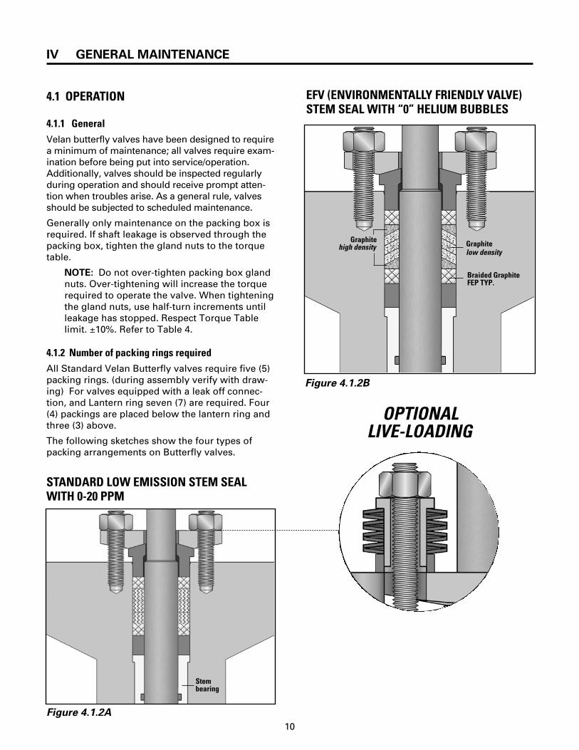
7.3 PROCEDURE FOR REMOVING MOTOR,HYDRAULIC OR PNEUMATIC ACTUATORS
The following instructions will give you a generalguide for removal and reinstallation of a hydraulicor pneumatic actuator. All hydraulic or pneumaticactuators have a connection between the valvestem and the drive sleeve of the actuator. All theseconnections are formed by a coupling and asquare key.
1. All Pressure must be relieved from both sidesof the valve before removing the actuator.
2. All air or hydraulic pressure must be relievedfrom actuator before disassembly.
3. The valve should be in a partially open posi-tion to remove any torque on the stem andload on the actuator fasteners. For springreturn actuators, this may be achieved by turn-ing the travel stops to a position which leavesthe valve in the slightly open position. Forfailed open actuators, the manual override
VII APPENDIX
system may need to be engaged to compressthe spring and position the valve in the slightlyopen position.
4. Match mark actuator orientation to the ValveBracket.
5. Remove all actuator fasteners.
6. Loosen coupling. Precaution: examine cou-pling for setscrew or any locking device beforeloosening it. Note: On some actuators, it isnecessary to rotate the actuator drive sleeve toremove this connection.
7. Remove the actuator from the valve.
8. If there is further work to be performed on thevalve, refer to the proper valve disassemblyand maintenance section in this manual.
7.4 SPARE PARTS
All parts of any valve can be ordered, but Velandoes not recommend changing all parts in thefield (above all for the first time). Changing theseparts may require special fitting. In these cases, itis best to get in touch with your local Velan repre-sentative who will help you determine the way torestore your valve with a minimum of time andexpense. When ordering spare parts, correctlydetermine which parts are required. Refer to thename plate on the valve for the correct figurenumber and order information. After this is done,present Velan with some of the following informa-tion:
1. Velan order number
2. Velan item number (if more than one item) tagnumber
3. Velan figure number and drawing number
Or
1. Customer order number
2. Customer item number (if more than one item)tag number
3. Valve size, type, pressure class and drawingnumber.

TERMS AND CONDITIONS OF SALE
CONTRACT: Orders are subject to acceptance bythe Velan Companies hereinafter referred to as theseller. No terms or conditions of Purchaser's ordercontrary to the Seller's terms and condition shallbe binding upon the Seller unless specificallyagreed to by the Seller in writing.
MINIMUM ORDER CHARGE: $500.00 net.PRICES: All quoted prices are subject to change bythe seller without prior notice and, unless other-wise stipulated by Seller, are understood to beF.O.B. Seller's plant, with delivery to carrier consti-tuting delivery to purchaser. Right to possession ofthe material to secure the payment of the purchaseprice shall remain in Seller until all paymentstherefore shall have been fully made. For the pro-tection of the Purchaser and the Seller, verbal cus-tomer orders must be confirmed by a formal writ-ten purchase order. If a written purchase order isnot received within ten days or a verbal order,product descriptions, quantities, specifications,etc., as set forth in Seller's acknowledgement andinvoice shall be conclusive and binding on bothparties. Any order that is shipped before receipt ofconfirmation which might have been entered incor-rectly and would require remedial action would befor the Purchaser's account.
TAXES: All prices are exclusive of taxes. Sales,use and other taxes, by whomsoever levied, are tobe paid by the Purchaser, and unless invoiced, areto be paid by the Purchaser directly to the appro-priate governmental agency.
DELIVERY: Delivery or shipment specified isSeller's best estimate and Seller shall not be liablefor delay in deliveries resulting from any causewhatsoever. Failure to ship on or near the estimat-ed date shall not entitle Purchaser to cancel hisorder without charge.
RETURN OF MATERIALS: Materials may bereturned only with prior written agreement ofSeller.
CANCELLATION: Cancellation of orders may bemade only with the Seller's written consent andPurchaser shall be subject to cancellation charges.PRODUCT WARRANTY: Seller warrants the equip-ment of its own manufacture to be free of defectsin material and workmanship, under normal useand proper operation for a period of one year fromthe date of shipment from Seller's plant. Seller'sobligation under warranty shall be strictly limited,at Seller's option, to: (i) furnishing replacementparts for or repairing without charge to Purchaser,F.O.B. Seller's plant or (ii) issuing written autho-rization for Purchaser or others to replace or repairwithout charge to Purchaser, at costs comparableto Seller's normal manufacturing costs those parts
proven defective, or (iii) in discharge of Seller'smaximum liability herewith, refunding all moniespaid by Purchaser to Seller for the Product and, atdiscretion of Seller, having the product removedand returned to Seller at Purchaser's expense. Alltransportation charges relative to corrective work,defective parts or replacement parts shall be borneby Purchaser. Purchaser shall give Seller immedi-ate notice upon discovery of any defect. Theundertaking of repairs or replacements byPurchaser or its agents without Seller's writtenconsent shall relieve seller of all responsibilityherewith.
Finished materials and accessories purchasedfrom other manufacturers are warranted only tothe extent of the manufacturer's warranty toSeller.
Any alteration in material or design of Seller's prod-uct or component parts thereof by Purchaser or oth-ers without written authorization by Seller voids allobligations of Seller regarding the product and anyassociated warranty herein stated or implied.
Seller's sole liability shall be exclusively as setforth herein, and Seller shall not be liable for anyincidental or consequential damages due to itsbreach of any warranty herein contained, or other-wise. Without limitation to the foregoing, in noevent shall Seller be liable for the loss of use ofthe product or of any other product, process,plant, equipment, or facilities of the Purchaser orend-user whether partially or wholly due todefects in material and /or workmanship and /ordesign of Seller's product, and in no event shallSeller be liable for removal of appurtenances orincidentals such as connections, pipe work andsimilar items of obstruction or for any costbrought about by the necessity of removing theproduct from its point of installation.
Seller makes no warranty of any kind whatsoever,expressed or implied, other then is specifically stat-ed herein; and there are no warranties of mer-chantability and/or fitness for a particular purposewhich exceed the obligations and warranties specifi-cally stated herein.
Parts furnished without charge as replacementsfor original parts under warranty are warranted forthat period of time during which the original partswarranty is effective.
ALL SHIPMENTS WILL BE F.O.B. PLANT LOCATION.SHIPMENTS WILL BE MADE VIA MOST ECONOMI-CAL CARRIERS UNLESS OTHERWISE REQUEST-ED.TERMS: NET 30 DAYS FROM DATE OF INVOICE:11⁄2% PER MONTH OF ALL OVERDUE ACCOUNTS,ALL TAXES EXTRA. PRICES SUBJECT TO CHANGEWITHOUT NOTICE.
31

PRINTED IN CANADA VEL–BFVM–2002
MANUFACTURING PROGRAM
Valve Product Line Size Pressure Applicablein mm Class Specifications
Forged pressure seal and bolted bonnet 2– 24 50–600 PS: ASME 600 – 4500 ASME B16.34gate, globe and check valves BB: ASME 150 –1500Small forged steel 1⁄4–2 8–50 ASME 150–2500 API 602, 606gate, globe and check valves ASME B16.34Forged steel Y-pattern globe valves 1⁄2 –4 15–100 ASME 900–4500 ASME B16.34Cast steel gate, globe and check valves 2 –60 50 –1500 ASME 150–1500 API 600Cast stainless steel 1⁄2 –24 15 –600 ASME 150–300 API 603gate, globe and check valves ASME B16.34Twin flapper wafer check valves 2 – 72 50 – 1800 ASME 125 – 2500 API 594
TAPPI TIS 405-8All stainless steel knife gate valves 2 –36 50–900 150 psiMSS SP-81
1⁄4 – 24 8–600 ASME 150–600 ASME B16.34Memory seal ball valve600–4000 WOG
General purpose ball valve 1⁄4 –12 8 – 300 Up to 300 Up to ASME B16.34Metal-seated ball valves 1⁄2 –24 15 –600 ASME 150–4500 ASME B16.34Butterfly valves 3– 36 80–900 ASME 150-300 API 609Bellows seal gate and globe valves 1⁄2 – 12 15–300 ASME 150–2500 ASME B16.34Cryogenic gate, globe, check, ball and butterfly valves 3⁄8 – 48 10–1150 ASME 150–1500 ASME B16.34
SALES OFFICES MANUFACTURING PLANTS U.S.A.Don Bowers94 Avenue CWilliston, VT 05495-9732Tel: (802) 864-3350Fax: (802) 865-3030
Ronald J. Harrington43 Wyckoff AvenueWaldwick, NJ 07463-1721Tel: (201) 670-0995Fax: (201) 670-6810
Paul R. Lee208 Lindbergh AvenueWilmington, DE19804-3316Tel: (302) 994-1176Fax: (302) 994-6156
Michael Midgley3160 Vera Valley DriveFranklin, TN37064Tel: (615) 599-5910Fax: (615) 599-6949
E. Harlan Dunk5409 Thornapple Ln.,Acworth, GA30101Tel: (770) 590-0909Fax: (770) 590-8144
Larry A. Woodworth1343 Paddock PlaceBartlett, IL 60103Tel: (630) 736-9395Fax: (630) 736-9397
Tony Boland45 W. Franklin StreetBellbrook, OH45305Tel: (937) 848-2011Fax: (937) 848-2144
U.S.A. VELAN VALVE CORPORATION94 Avenue CWilliston, VT 05495-9732Tel: (802) 863-2561Fax: (802) 862-4014
ENGLANDVELAN VALVES LTD.Unit 1, Pinfold Road,Lakeside Business Park,Thurmaston, LeicesterLE4 8AS EnglandTel: 44-116 269-5172Fax: 44-116 269-3695
FRANCEVELAN S.A.S90, rue Challemel Lacour69367 Lyon Cedex 7 FranceTel: (33) 4-78-61-6700Fax: (33) 4-78-72-1218
PORTUGALVELAN VÁLVULASINDUSTRIAIS, LDA.Av. Ary dos Santos1679-018 FamoesPortugalTel: (351-21) 934-7800Fax: (351-21) 934-7809
TAIWANVELAN-VALVACP.O. Box 2020Taichung, Taiwan, R.O.C.Tel: (04) 2792649Fax: (886) 42750855
CANADAVELAN INC.7007 Côte de LiesseMontreal, QC H4T 1G2Tel: (514) 748-7743Fax: (514) 748-8635
VELAN INC.2125 Ward AvenueMontreal, QC H4M 1T6Tel: (514) 748-7743Fax: (514) 748-8635
VELAN INC.550 McArthur Ave.Montreal, QC H4T 1X8Tel: (514) 748-7743Fax: (514) 341-3032
VELAN INC.1010 Cowie StreetGranby, QC J2J 1E7Tel: (450) 378-2305Fax: (450) 378-6865
PROQUIP835 Fourth LineOakville, ON L6L 5B8Tel: (905) 842-1721Fax: (905) 849-0923
KOREAVELAN LTD.1060-4 Shingil-DongAnsan City, Kyunggi-doKorea 425-833Tel: (82) 31-491-2811Fax: (82) 31-491-2813
EUROPEBrian HallVELAN VALVES LTD.Cambridge Rd., WhetstoneLeicester LE8 6LH EnglandTel: 44-6-275-0206Fax: 44-6-275-0224
J.C. CennacVELAN S.A.S90, rue Challemel Lacour69367 Lyon Cedex 7FranceTel: (33) 4-78-61-6700Fax: (33) 4-78-72-1218
INDIAS.GiridharB-708 VardhamanApartmentsMayur Vihar-Phase 1Delhi 110091 IndiaTel: 91-11-271-2196Fax: 91-11-225-3533
CHINARoom 2906 of Newtown #3 BuildingNo. 88 Jinguo RoadChaoyana DistrictBeijing, China 100022Tel: 86-10-65665088Fax: 86-10-65675744
JAPANTak Sakamoto4-31-3 Kamimeguro,Meguro-ku , Tokyo 153-0051 JapanTel: 81-3-3792-1891Fax: 81-3-3792-1891
CANADAPaul Dion /Jacques Godbout7007 Côte de LiesseMontreal, QCH4T 1G2Tel: (514) 748-7743Fax: (514) 748-8635
George S. Lysakowski871 Kowal DriveMississauga, ONL5H 3T3Tel: (905) 278-7522Fax: (905) 278-8155
Bill Patrick8825, 51st AvenueEdmonton, AB T6E 5H1Tel: (780) 465-1122Fax: (780) 465-0403
Leo Shewchuk17 Simcrest Manor S.W.Calgary, AB T3H 4K1Tel: (403) 232-6482Fax: (403) 686-6485
MEXICO, CENTRAL & SOUTH AMERICASergio PensottiVELAN VALVE CORP.730 N. Post Oak RoadSuite 311Houston, TX77024Tel: (713) 682-1837Fax: (713) 682-6071
Charles Pogue /B. Lawson / T. Harfield /M. Tilley730 N. Post Oak RoadSuite 311Houston, TX77024Tel: (713) 682-1084Fax: (713) 682-6071
Christopher G. Hiett21931 Harborbreeze LaneHuntington Beach, CA92646Tel: (714) 965-6277Fax: (714) 965-6737
John Flynn289 Antioch RoadLake Lure, NC 28746Tel: (828) 625-9441Fax: (828) 625-9437
Joe Denny1638 Estate CircleNaperville, IL60565Tel: (630) 579-1833Fax: (630) 579-1834
David Brodnax503 Comanche TrailWest Monroe, LA71291Tel.: (318) 396-7517Fax: (318) 396-4995
Frank Keegan9007 Highland Road, Unit 14Baton Rouge, LA70810Tel: (225) 767-7965Fax: (225) 767-8160
SINGAPOREGary Tan18 Eastwood PlaceSingapore 486543Tel: (65) 246-1108 Fax: (65) 244-9791
AUSTRALIAJim Thanos25 Beagle St.,Mosman Park, Western Australia 6012Tel: (61) 8 9284-2255 Fax: (61) 8 9284-6314
DISTRIBUTIONCENTERS &SALES OFFICESU.S.A.VELCALDave Frolich537 Stone Road, Unit "A"Benicia, CA94510Tel: (707) 745-4507Fax: (707) 745-4708
VELEASTScott Stewart605 Commerce Park Drive SEMarietta, GA30060Tel: (770) 420-2010Fax: (770) 420-7063
GERMANYVELAN GmbH Wolfgang MaarDaimlerstrasse 8 D-47877 Willich Tel: (49) 2154/4938-00Fax: (49) 2154/4938-99
Velan’s valve distributors are located worldwide.
GENERAL INFORMATIONTel: (514) 748-7743Fax: (514) 748-8635Web: http://www.velan.com


![epssweden.comepssweden.com/files/Stop [VENS] and Regulating Valves [VENR] acc.pdf · asme/ansi b16.10 asme-ansi b16.5 asme-ansi b16.10 asme/ansi b16.25 ... 14 43 85 128 48 96 144](https://img.pdfslide.us/doc/110x75/5a9ff4687f8b9a8e178d6630/vens-and-regulating-valves-venr-accpdfasmeansi-b1610-asme-ansi-b165-asme-ansi.jpg)