Embed Size (px)
Citation preview
1 © 2010 AIMS Education Foundation
TopicSimple machines
Key QuestionWhat simple machines are found in an internal com-bustion engine?
Learning GoalsStudents will:• constructaworkingmodelofaninternalcombus-
tion engine that has a piston, connecting rod, and crankshaft;
• identifythesimplemachinesinthemodel;and• determine the relationshipbetween thediameter
of the circle along which the lower end of the con-necting rod moves and the distance the piston travels.
Guiding DocumentsProject 2061 Benchmarks• Scienceisanadventurethatpeopleeverywherecan
takepartin,astheyhaveformanycenturies.• Engineers,architects,andotherswhoengage in
designand technologyuse scientificknowledgetosolvepracticalproblems.
• Throughout all of history, people everywherehaveinventedandusedtools.Mosttoolsoftodayaredifferentfromthoseofthepastbutmanyaremodificationsofveryancienttools.
NRCStandards• Mathematicsisimportantinallaspectsofscientific
inquiry.• Inmostchemicalandnuclearreactions,energyis
transferredintooroutofasystem.Heat,light,me-chanicalmotion,orelectricitymightallbeinvolvedinsuchtransfers.
• Scientists and engineerswork inmanydifferentsettings,includingcollegesanduniversities,busi-nessesandindustries,specificresearchinstitutes,andgovernmentagencies.
NCTMStandards2000*• Use geometricmodels to represent and explain
numericalandalgebraicrelationships• Recognizeandapplygeometricideasandrelation-
shipsinareasoutsidethemathematicsclassroom,suchasart,science,andeverydaylife
SciencePhysicalscience simple machines wheel and axle
TechnologyIndustrial revolutionInternal and external combustion engines
EngineeringMechanical engineering motion conversion
MathGeometry circle diameterMeasurement length
Integrated ProcessesModelingObservingCollecting and recording dataComparing and contrasting
MaterialsPushpinsHole punches ¼-inchRulersGluestickWhite glueScissorsRoundtoothpicksPlasticdrinkingstraws,15/64-inchdiameterPaper fasteners, ½-inchCardstockpatterns
Background Information Inthisactivity,studentsconstructaworkingmodelofaninternalcombustionengine(ICE)ofthetypeusedincarsandtrucks.Themovingpartsinthemodelarethecrankshaft,thecrank,theconnectingrod,andthepiston. In an internal combustion engine, the linear mo-tionofoneormorecylinder-shapedpistons,movinginacylinder-shapedcombustionchamber,istransformedintotherotarymotionofthecrankandcrankshaft.Thisrotarymotioniseventuallytransformedintotherotarymotionofthedrivingwheelsinthecarortruck.
2 © 2010 AIMS Education Foundation
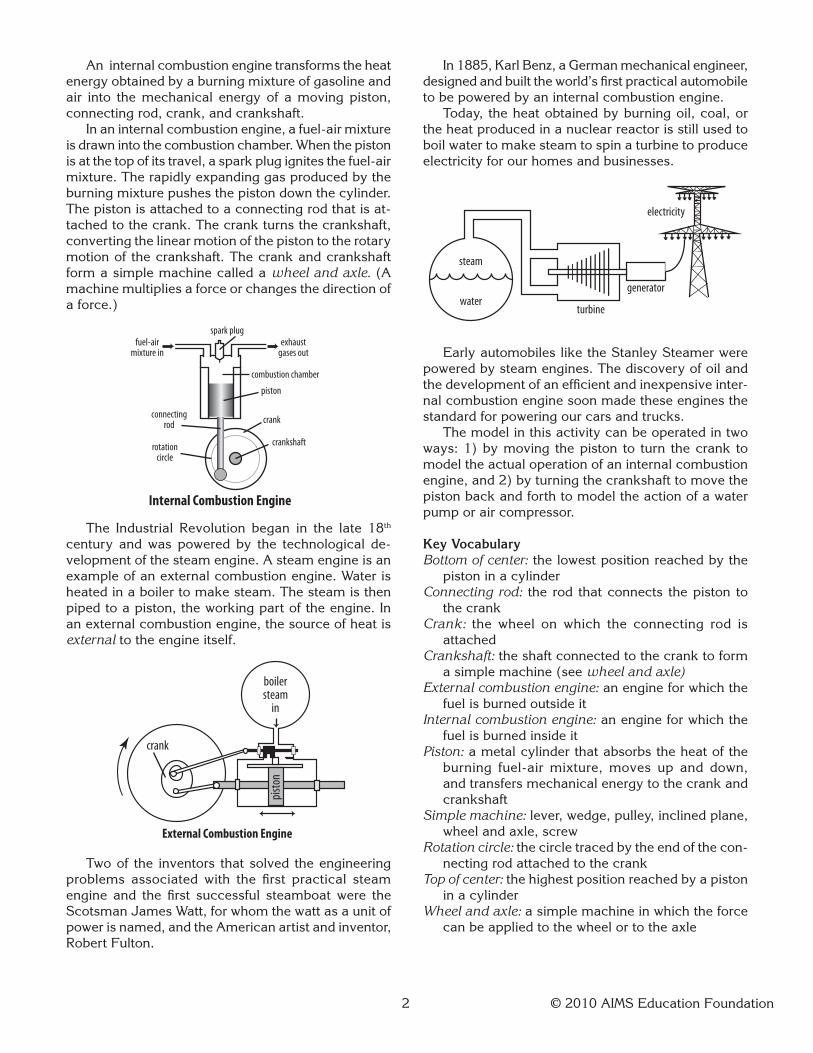
An internal combustion engine transforms the heat energyobtainedbyaburningmixtureofgasolineandair into themechanical energyof amovingpiston,connectingrod,crank,andcrankshaft. In an internal combustion engine, a fuel-air mixture is drawn into the combustion chamber. When the piston isatthetopofitstravel,asparkplugignitesthefuel-airmixture.Therapidlyexpandinggasproducedbytheburningmixturepushesthepistondownthecylinder.Thepistonisattachedtoaconnectingrodthatisat-tachedtothecrank.Thecrankturnsthecrankshaft,convertingthelinearmotionofthepistontotherotarymotionofthecrankshaft.Thecrankandcrankshaftform a simple machine called a wheelandaxle.(A machine multiplies a force or changes the direction of a force.)
The Industrial Revolution began in the late 18th century andwaspoweredby the technological de-velopment of the steam engine. A steam engine is an example of an external combustion engine. Water is heatedinaboilertomakesteam.Thesteamisthenpipedtoapiston,theworkingpartoftheengine.Inan external combustion engine, the source of heat is external to the engine itself.
Twoof the inventors thatsolved theengineeringproblems associated with the first practical steam engine and the first successful steamboat were the Scotsman James Watt, for whom the watt as a unit of power is named, and the American artist and inventor, Robert Fulton.
In1885,KarlBenz,aGermanmechanicalengineer,designed and built the world’s first practical automobile tobepoweredbyaninternalcombustionengine. Today,theheatobtainedbyburningoil,coal,orthe heat produced in a nuclear reactor is still used to boilwatertomakesteamtospinaturbinetoproduceelectricityforourhomesandbusinesses.
EarlyautomobilesliketheStanleySteamerwerepoweredbysteamengines.Thediscoveryofoilandthe development of an efficient and inexpensive inter-nal combustion engine soon made these engines the standardforpoweringourcarsandtrucks. Themodelinthisactivitycanbeoperatedintwoways:1)bymoving thepiston to turn thecrank tomodel the actual operation of an internal combustion engine,and2)byturningthecrankshafttomovethepistonbackandforthtomodeltheactionofawaterpump or air compressor.
Key VocabularyBottomofcenter:thelowestpositionreachedbythepistoninacylinder
Connectingrod: the rod that connects the piston to thecrank
Crank: the wheel on which the connecting rod is attached
Crankshaft:theshaftconnectedtothecranktoforma simple machine (see wheelandaxle)
Externalcombustionengine: an engine for which the fuel is burned outside it
Internalcombustionengine: an engine for which the fuel is burned inside it
Piston:ametalcylinderthatabsorbstheheatoftheburning fuel-air mixture, moves up and down, andtransfersmechanicalenergytothecrankandcrankshaft
Simplemachine:lever,wedge,pulley,inclinedplane,wheel and axle, screw
Rotationcircle:thecircletracedbytheendofthecon-nectingrodattachedtothecrank
Topofcenter:thehighestpositionreachedbyapistoninacylinder
Wheelandaxle: a simple machine in which the force can be applied to the wheel or to the axle
spark plugexhaust
gases outfuel-air
mixture in
combustion chamber
piston
crank
crankshaftrotationcircle
connectingrod
Internal Combustion Engine
External Combustion Engine
pisto
n
boilersteam
in
crank
water
steam
turbine
generator
electricity

3 © 2010 AIMS Education Foundation
Management1. Printallpatternpagesoncardstock.Eachstudent
or group will need one piston, one connecting rod, one crank, one crank support, one set of threecrankshaft spaces, one cylinderwall guide, andone base pattern.
2. Step by step directions are included. They canbe presented to students as handouts that require themtoreadandfollowthedirections.Thisalsorequires copies to be made for each student or group. The directions can be projected, stillrequiring students to read and follow them, but requiring only one copy. The drawback is thatfasterworkersmustwaitforthosewhodon’tworkasfast.Theprocedurescanalsobemodeledusingthe construction video at
http://aimsedu.org/stem
orwithyoumodeling theprocess.Thismethodrequires no copies of instructions, but it does requirethewaittimebyfasterworkers.
3. It’s important that students understand and follow the techniques described in How toScore,Cut,Fold,andGlueCardStock.Thosethatdowilleasilyconstructaworkingmodel.
4. Plasticstrawswitha15/64-inchdiameterfitsnuglyintotheholemadebyaquarter-inchpaperpunchIt is often easier to find these straws sold as flexible straws.Ifyouuseflexiblestraws,simplyhavestu-dents cut off the shorter, flexible end.
5. Taketimetoconstructamodel.Doingsowillhelpyouidentifypotentialproblemareasforoneormoreofyourstudentsandgiveyoutimetodevelopanyappropriatestrategiesbeforedoingtheactivitywithyourclass.
6. Setmaterialsinacentrallocationsothatstudentscan get them as needed.
Procedure1. ShowthestudentsyourmodeloftheICE.Explainto them that ICE is an acronym for InternalCombustion Engine. Tell them that they willbemakingamodel todiscoverhowengineerssolved the problem of converting linear motion intorotarymotion.
2. AsktheKeyQuestion and state the LearningGoals.3. Show students where the materials are located.
Use one of the methods described in Management2 for construction. Students should construct the model’s components in the following order: the piston,theconnectingrod,thecrank,attachingthecrankshafttothecrank,crankshaftsupport,andthen putting the model together.
4. Whenmodels are finished, let students explorehowtheywork.Invitethemtoturnthecrankinonedirectionsotheycanobservetheinteractionofthemoving parts.
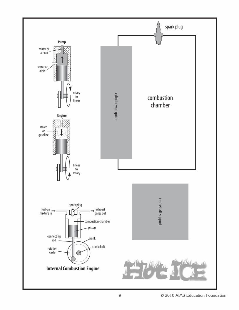
5. Makecertainthatstudentsnoticethetwodiagramson the model’s base. Explain that the picture la-beled Pump demonstrates the action of a piston pump.Inapumporaircompressor,likeoneusedtoinflatetires,anelectricmotorturnsthecrankshaftthat pushes the piston up and down pumping water orcompressingair.Turningthecrankshaftofthemodel demonstrates using the model as a pump.
6. Drawthestudents’attentiontothepicturelabeledEngine.Tellthemthatthisillustrateshowtheburn-ing fuel-air mixture pushes down on the piston to turnthecrank.Havestudentsputthepistonoftheirmodel at top center (the highest position reached bythepiston).Tellthemtomovethepistontothebottom center (the lowest position). Let them see that the piston can go no further down, instead it movesbackup.(Thecrankofanengineisdesignedtoonlyturninonedirectionsoalargewheelcalleda flywheelmountedonthecrankshaftstoresenergytopushthecrankaroundandpushthepistonbackto top center. Most internal combustion engines havemore than one cylinder so thatwhen onepiston is at or near bottom center, another piston is moving down, which helps push the other piston up.Themorepistons,thesmoothertheoperationof the engine.)
7. Distributethestudentpage.Havestudentsanswerthe questions. End with a discussion of observa-tions and applications learned.
Connecting Learning1. What simple machine is evident in our model? [the
wheel and axle]2. In an internal combustion engine, the parts arenotcalledawheelandaxle.Whatare theycalled?[Thewheel is thecrank,andtheaxle isthecrankshaft.]
3. How does the model convert the direction of motion? [When you turn the crankshaft (rotarymotion), the piston moves up and down (linear motion). You can also move the piston up and down toturnthecrank.]
4. Howisthemodellikearealinternalcombustionengine? [The model shows how the piston,connectingrod,crank,andcrankshaftconvertthedirection of motion.]
5. Howdoesyourmodeldiffer froma real internalcombustion engine? [A real ICE often has more than one piston, is made of metal, has to have oil to lubricate the moving parts, etc.]
6. What relationship did you find between thediameterofthecrankwheretheconnectingrodis attached and the distance the piston travels? [Thedistance thepistonmoves is the sameasthe diameter of the circle the crank end of theconnecting rod traces.]

4 © 2010 AIMS Education Foundation
7. If the distances youmeasured were not thesame,whatcouldexplain thedifferences? [Thepaperfastenersdonotfillanyoftheholes.Thismeansthepartsdon’tfittightlytogether,therebyintroducing error.]
8. What would you need to do if you wanted tomakethepistonmoveagreaterdistance?[Usealargercrank.]
9. Whatareyouwonderingnow?
Extensions1. Challenge interested students to do a research reportonJamesWatt,RobertFulton,KarlBenz,orHenryFold.
2. Askstudents if theyhavearelativewhohasoldenginepartstheywouldlettheclassborrowtoseeactual components.
* Reprinted with permission from PrinciplesandStandards forSchoolMathematics,2000bytheNationalCouncilofTeachersof Mathematics. All rights reserved.
5 © 2010 AIMS Education Foundation
Key Questions
Learning Goal
•constructaworkingmodelofaninternalcombustion engine that has a piston, connectingrod,andcrankshaft;
• identifythesimplemachinesinthemodel;and
•determinetherelationshipbetweenthediameter of the circle along which the lower end of the connecting rod moves and the distance the piston travels.
What simple machines are found in an internal combustion engine?

6 © 2010 AIMS Education Foundation
snipsnip
dashedline
dotted line
Do not cut alongdashed or dotted lines.
ballpoint pen
line to bescored
piece to befolded
ruler
valley fold
mountain fold
wet but not white!
white glue
toothpick
glue clinging to tipof toothpick
glue tab
toothpick
Cutting to a Corner
Scoring
Gluing
How to Cut, Score, and Glue Card StockHow to Cut, Score,
and Glue Card Stock
For large areas, using a glue stick is the fastest and easiest way to glue card stock. Be sure to press hard on the glued sections. If possible, use a paper clip to clamp the pieces together. For small areas or where maximum strength is needed, use white glue. Nothing will ruin a project faster than the application of too much white glue. Put a bean-sized drop of glue on a piece of card stock left over from cutting out the pattern. Dip the end of a round toothpick in the glue, and apply only the glue clinging to the end of the toothpick to the piece to be glued. Use the tip or tapered end of the toothpick to spread the glue evenly over the surface of the piece.
Every piece of a card stock pattern will be outlined in solid, black lines. The pattern may also contain dashed and/or dotted lines. Always cut along the solid, black lines. Never cut along dashed or dotted lines. Whenever possible, cut to a corner. This prevents you from accidentally creasing or folding the piece and makes for easier cutting.
It is easy to neatly fold card stock if the line along which you wish to fold is first traced over with a ballpoint pen or pencil. (Ballpoint pens that are out of ink are ideal for this purpose.) Use a ruler to score along straight lines.

7 © 2010 AIMS Education Foundation
crank
apply gluehere
valley fold
dashed line
mountain fold
dotted line
cylinder wall guide
pistonapply glue
hereapply glue
here
connecting rod
crankshaft spacers
ICE Pattern Pieces
8 © 2010 AIMS Education Foundation
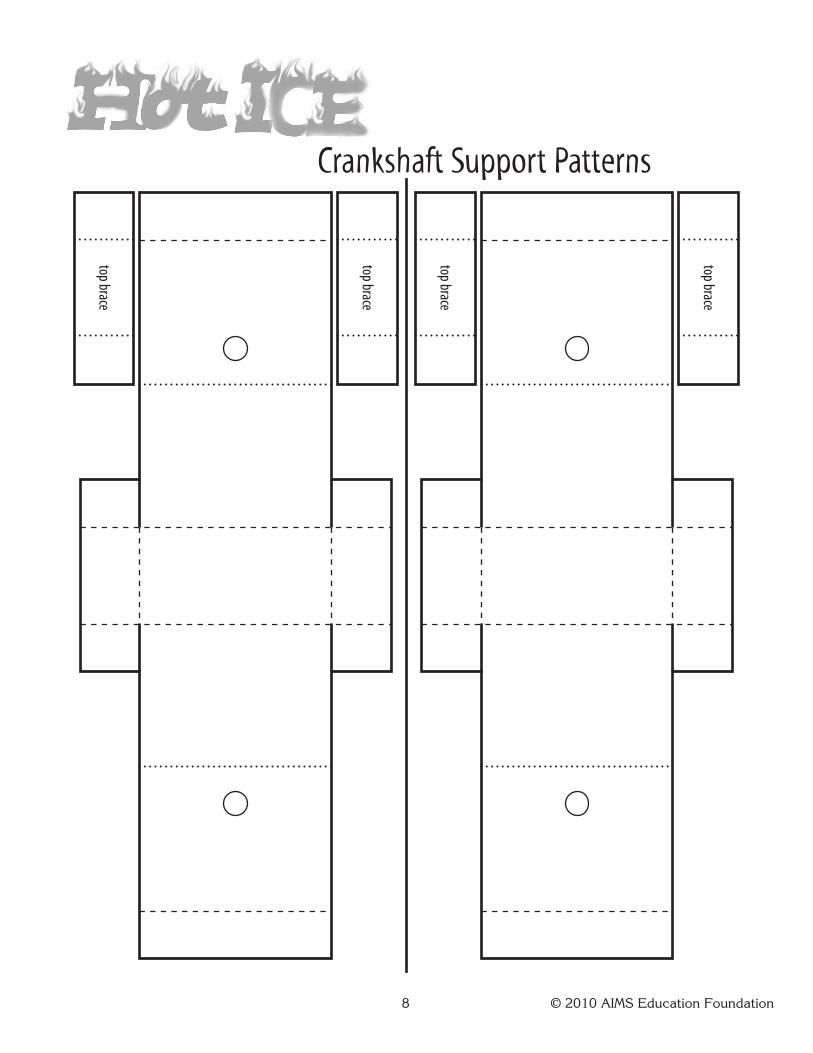
top brace
top brace
top brace
top brace
Crankshaft Support Patterns
9 © 2010 AIMS Education Foundation
cylinder wall guide
crankshaft support
water orair in
steamor
gasoline
rotaryto
linear
linearto
rotary
water orair out
Pump
Engine
spark plug
spark plug
combustionchamber
exhaustgases out
fuel-airmixture in
combustion chamber
piston
crank
crankshaftrotationcircle
connectingrod
Internal Combustion Engine

10 © 2010 AIMS Education Foundation
piston
apply glue
here
apply
glue
here
connecting rodcr
ank
apply g
lue
here
Construction Instructions
Constructing the Piston, Connecting Rod, and Crank
Materials needed:piston pattern piececonnecting rod pattern piececrank pattern pieceruler
crank
crank
crank
cut and punchcenter hole
scrap of card stock
scissorspushpinhole punchglue stick
1. Use the pushpin to score along the dashed and dotted lines on all three pattern pieces.
2. Cut along the solid lines.
3. Valley and mountain fold the pattern pieces.
4. On the piston piece, apply glue to the shaded face and the face behind the piston. Press flat and punch a hole in the bottom of the piston.
5. On the connecting rod piece, apply glue to the shaded face and the face behind the connecting rod. Press flat and punch two holes as indicated.
6. On the crank piece, apply glue to the shaded face and the face behind the crank. Press flat.
7. Cut out the crank circle. Cut along the shorter dark line. Carefully bend down the edge, and punch the two holes in the crank.
8. Heal the cut by gluing a piece of card stock scrap over the cut. Trim along the edge of the crank.

11 © 2010 AIMS Education Foundation
pushpin
1⁄8-inch
toothpick
Construction Instructions
shaftsupportspacers
crank
crank
spacersapply
white gluehere
Attaching the Crankshaft to the Crank
Materials needed:plastic drinking straw pushpin2 round toothpicks hole punch3 crankshaft spacer pattern pieces glue stickruler white gluescissors
1. If you have a flexible straw, cut off the shorter, flexible end and discard.
2. Measure 1/8-inch from the end of the straw and use the pushpin to poke through the mark and out the opposite side of the straw.
3. Push the toothpick through the holes and break the ends to form a short shaft through the end of the straw.
4. Cut out the three crankshaft support spacer patterns. Cut, score, fold, and glue the three spacers. Punch a hole on the circle face of each spacer.
5. Glue two spacers over the center hole in the back of the crank piece and use the toothpick end of the straw to center the spacers before the glue sets.
6. Look at the front face of the crank and check if the end of the straw extends past the face of the crank. If so, remove the straw and glue the third spacer over the first two.
7. Set the toothpick end of the straw in the spacers. Use the tip of a second toothpick to apply white glue over the ends of the toothpick in the straw. The white glue will form a strong bond between the wood in the toothpick and the card stock.
8. Set aside to dry.

12 © 2010 AIMS Education Foundation
apply glue tobottom face with printed hole
apply glue toinsides of tabs punch
holes
bracepieces
piston
crank
connecting rod
Construction InstructionsAttaching the Crankshaft Support and Putting the Pieces Together
Materials needed:crankshaft support pattern ruler base pagescissors pushpin 2 paper fastenershole punch glue stick cylinder wall guide pattern
1. Score, cut, and fold the support piece and the two brace pieces.
2. Apply glue to the face under the printed holes, and press the faces together as shown.
3. Apply glue to the insides of the bottom tabs and press each tab in place.
4. Glue the top brace pieces in place and punch the holes in the sides.
5. Apply glue to the bottom of the crankshaft support piece and set the piece on the shaded area in the bottom right corner.
6. Use the two paper fasteners to attach the connecting rod to the crank and piston.
7. Insert the end of the straw through the two holes in the support piece.
8. Score along the dotted and dashed lines of the cylinder wall guide pattern. Mountain fold and valley fold the pattern. Glue the pattern to the shaded area on the base labeled cylinder wall guide. Check that there is a center groove in which the piston can slide.
9. Insert the piston in the cylinder wall guide. Adjust the straw in the crankshaft support so that the crank, connecting rod, and piston are in line. Turn the straw to see the model in action.
13 © 2010 AIMS Education Foundation
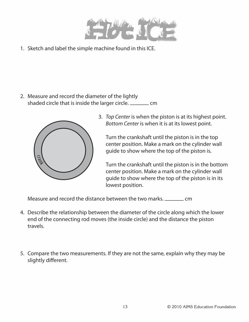
1. Sketch and label the simple machine found in this ICE.
2. Measure and record the diameter of the lightly shaded circle that is inside the larger circle. cm
3. Top Center is when the piston is at its highest point. Bottom Center is when it is at its lowest point.
Turn the crankshaft until the piston is in the top center position. Make a mark on the cylinder wall guide to show where the top of the piston is.
Turn the crankshaft until the piston is in the bottom center position. Make a mark on the cylinder wall guide to show where the top of the piston is in its lowest position.
Measure and record the distance between the two marks. cm
4. Describe the relationship between the diameter of the circle along which the lower end of the connecting rod moves (the inside circle) and the distance the piston travels.
5. Compare the two measurements. If they are not the same, explain why they may be slightly different.
crank
14 © 2010 AIMS Education Foundation
Connecting Learning
1. What simple machine is evident in our model?
2. In an internal combustion engine, the parts are not called a wheel andaxle.Whataretheycalled?
3. How does the model convert the direction of motion?
4.Howisthemodellikearealinternal combustion engine?
5.Howdoesyourmodeldifferfroma real internal combustion engine?

15 © 2010 AIMS Education Foundation
Connecting Learning
6.Whatrelationshipdidyoufind between the diameter ofthecrankwheretheconnecting rod is attached and the distance the piston travels?
7.Ifthedistancesyoumeasuredwere not the same, what could explain the differences?
8.Whatwouldyouneedtodoifyouwantedtomakethepistonmove a greater distance?
9.Whatareyouwonderingnow?
![Introduction of Advanced Measutal (Model : CDG-0004)220]20071120173728.pdf · 1 Crank Throw Measuring Point Purpose of measuring the crankshaft deflection Checking the rectilinearity](https://img.pdfslide.us/doc/110x75/5ab6cfe67f8b9a2f438e131c/introduction-of-advanced-measutal-model-cdg-0004-22020071120173728pdf1-crank.jpg)