Embed Size (px)
Citation preview
Topic-2- Storage Devices & Interfacing
1 | P a g e
Recording Techniques: FM, MFM , RLL, perpendicular recording
Describe Modified Frequency Modulation (MFM) and Run Length limited (RLL)
techniques of recording with suitable example.
(For MFM explanation 2 marks, Waveform or coding 2 marks) (For RLL explanation 2
marks, Waveform or coding 2 marks)
Three most common encoding methods are:
1. FM encoding method
2. MFM encoding method
3. RLL encoding method
1. FM Encoding Scheme:
FM or Frequency Modulation was the original data-encoding scheme used for storing the
data on the magnetic recording surface.
This method of data encoding is also known as the “Single density recording”.
In this method, a clock signal is put with every data signal on the recording surface. This
clock signal is used for synchronizing the read operation, as there will always be a clock
signal, whether the data signal is there or not.
In this FM method of data recording a 1 bit is stored as two pulses(one clock pulse and
one data pulse), and a o bit is stored as a one pulse and one gap or no pulse.
For example, a binary number 1011 will be stored as PP PN PP PP
Course Code – CM-4-G Subject – CHM (17428) Subject Teacher –Prof. Y. S. Modhe
2 | P a g e
2. MFM Encoding Scheme:
More data can be stored on the same surface or the data storage density can be increased,
if the number of pulses required to store the data can be minimized.
When minimizing the pulses, one should be careful that the number of no pulses together
should not be very long; otherwise the disk controller may go out of synchronization with
the data.
The MFM (modified frequency modulation) method of data storage, by reducing the
number of pulses, is able to store more data without any data and synchronization number
of pulses, is able to store more data without any data and synchronization loss. In MFM
recording the 0s and 1s are encoded as given below
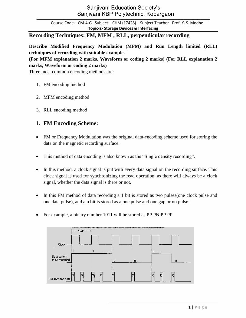
1 is always stored as no pulse, and a pulse(NP)
0, when preceded by another 0, is stored as a pulse, and no pulse(PN)
0, when preceded by a 1, is stored as two no pulses(NN)
If you store 1001 on the disk surface using the MFM storage method, it would be stored
as NP NN PN NP.
3. RLL Encoding Scheme
The RLL is encoding or the run length limited encoding is the most common encoding
scheme used in the hard disk storage.
This encoding scheme can be more accurately called as 2,7 RLL encoding because in this
scheme in a series or in a running length the minimum number of 0s next to each other is
two, and the maximum number of 0s together can not be more than seven.
The RLL encoding scheme can store 50 percent more information than MFM encoding
scheme on a given surface and it can store three times as much information as the FM
encoding scheme. The Run length Limited name comes from the minimum number (run
Length) and maximum number (run Limit) of “no pulse” values allowed between two
pulses.
3 | P a g e
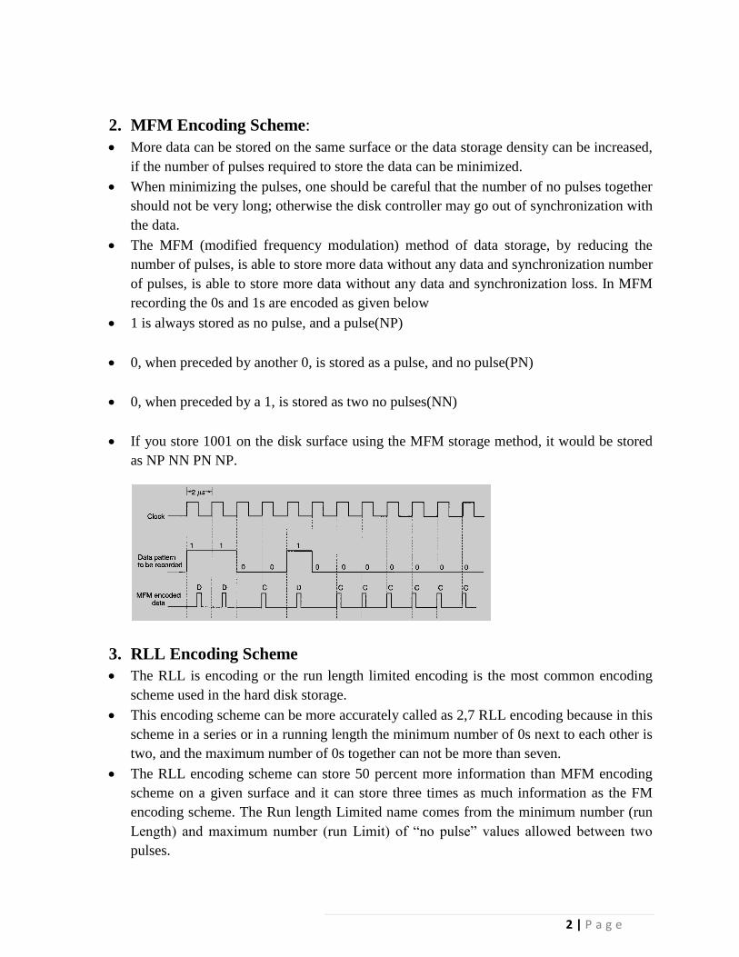
For the RLL encoding, an encoder/decoder (Endec) table is used to find the pulse signal
to be used for different data bit groups. Endec table used by the IBM to convert bit
information to the pulse signal is shown below
Data Bit Pulse Encoding
10 NPNN
11 PNNN
000 NNNPNN
010 PNNPNN
011 NNPNNN
0010 NNPNNPNN
0011 NNNNPNNN
For example, if you want to encode a byte 100011 to proper RLL pulse signal then the
Bit 10 can be encoded as NPNN
Bit 0011can be encoded as NNNNPNNN
4. Perpendicular Encoding
Virtually all hard drives record data using longitudinal recording which stores magnetic
bits horizontally across the surface of the media.
However perpendicular recording which aligns magnetic signals vertically on the media
surface has the potential to achieve higher data intensities because vertically oriented
magnetic bits use less space than longitudinally stored bits.
Hard Disk Construction
4 | P a g e
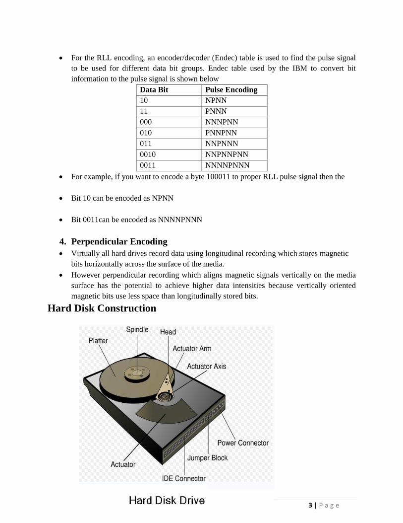
A hard disk drive is made up of several physical components
1) Disk platters
2) Read/write heads
3) Head actuator mechanism
4) Spindle motor
5) Logic board
6) Cables and connectors
7) Bezel / Front Plate
8) Air Filter
Hard Disk Platters(Disks)
The platters stores information. It comes in varying sizes like 5.12”, 3.14”,0.85” etc. The
physical size of a drive is expressed as the size of the platters
Most hard disk have two or more platters
Platters were originally made from an aluminium/magnesium alloy which provides
bothe strangth and light weight
All modern drives use glass or glass ceramic plates.
Read/Write Heads
A hard disk drive usually has one read/write head for each platter surface(meaning
that each platter has two sets of read/write heads-oneee for top side and one for
bottom side
These heads are connected on asingle movement mechanism so heads across the
platters in unison.
The HDD uses various types of heads for read/write purpose.
Ferrite head
Metal-In-Gap Head, Thin Film Head
Magneto Resistive Head
Giant Magneto Resistive Head
Head Actuator Mechanism
This mechanism moves the heads across the disk and positions them accurately above
the desired cylinder.
Two basic Categories are used
Stepper Motor Mechanism
Voice Coil Actuator
Stepper Motor actuators were commonly used on hard drives made during the 1980s
and early 1990s with capacities of 100MB or less
Floppy disk drives position their head by using a stepper motor actuator
All hard disk drives being manufactures today use voice coil actuator.
Voice Coil Actuator
5 | P a g e
- The two main types of voice coil positioner mechanisms are
Linear Voice Coil Actuators
Rotary Voice Actuators
Spindle Motor
The spindle motor spins the platters connected to spindle. The motor is directly
connected to the spindle of platters. These platters revolve at exactly 3600 rpm to 1500
rpm. The speed of motor has to be controlled very precisely.
Normally a feedback loop is employed in the control electronics to monitor the
speed. The speed control is fully automatic.
Logic Boards
- A disk drive will have a board containing the electronics that control the drive’s spindle
and headactuator systems These are calledlogic boards.
- They present data to the controller in aplanned format.
- They may be removed and replaced to rectify a logic board problem.
Cable and Connectors
Cable and connectors are used to connect HDD to the main computer system.
All hard disj drive contains connections for Data/Control interface connector, Power
connector
Bezel/ Front Faceplate
Bezel is the front faceplate provided on most of the hard disk drives.
Air Filters
Nearly all hard disk drives have two air filter. One is called the recirculating filter
and the other is called either a barometric or breather filter.
These filters are permanently sealed inside the drive and are designed never
to be changes for the life of the drive.
A hard disk on a PC system does not circulate air from inside to outside the
HDD or vice versa.
The recircualting filter permanently installed inside HDA is designed to filter
only small particles. Scraped off platters during head takeoffs and landings.
Terms Related to Harddisk
Explain following terms related to hard disk-cluster, cylinder, sector, landing zone.(Each
term – 1M.)
6 | P a g e
Cluster
When OS writes some information on the hard disk, it does not allocate the space sector
wise, instead uses a new unit of storage called “Cluster”
Clusters are the minimum space allocated by DOS when storing any information on the
disk
Even to store only one byte long information on the disk requires minimum one cluster
area on the disk surface
A cluster can be made up of one or more sectors, it depends on disk type being used.
This reduces the size of FAT that DOS uses to keep track of the used and the empty disk
space
First cluster no. is taken as 2
Clusters are used to allocate the storage area for data area only, FAT and directory areas
are not allocated according to the cluster size
Cylinder: (Diagram optional); If given, Diagram- ½M.
Cylinder
Same tracks of different platters form an imaginary cylinder like structure
Data is stored cylinder by cylinder
7 | P a g e
All tracks on a cylinder are written and then the R/W head moves to the next cylinder.
This reduces movement of R/W head and increases the speed of read and write operation
Sector
A track is a big area to store data( 5000 bytes). Hence tracks are divided into sectors
The formatting program divides disk surface into sectors by writing magnetic pattern on
disk surface
Different HDD capacities have different number of tracks
512 byte data can be stored in each sector. Sector no. starts from 1
Landing zone:
This setting specifies the cylinder to which the BIOS should send the heads of the hard
disk when the machine is to be turned off. This is where the heads will "land" when they
spin down. Modern drives automatically park the heads in a special area that contains no
data when the power is turned off. Therefore this setting is meaningless and is typically
ignored.
Most BIOSes set this value to be the largest cylinder number of the logical geometry
specified for the disk when auto detection takes place. So if the drive has 6,136 logical
cylinders, the landing zone will be set to 6,135. In any event a modern IDE drive will
ignore this setting and auto-park by itself.
Zone Recording
One way to increase the capacity of a hard drive during the low level format is to create
more sectors on the disks Outer cylinders than on the inner ones.
Because they have a larger circumference the outer cylinders can hold more data. Drives
that use zoned recording split the cylinders into groups called zones, with each
successive zone having more sectors per track as you move outward from the center of
disk.
8 | P a g e
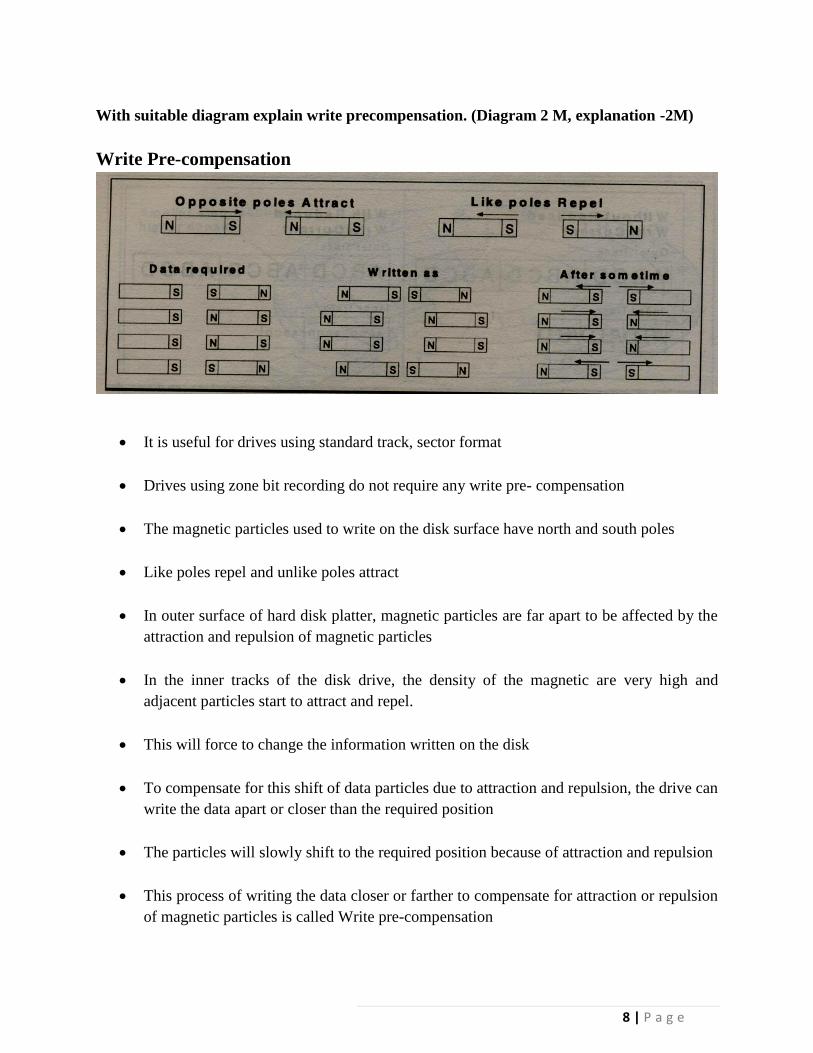
With suitable diagram explain write precompensation. (Diagram 2 M, explanation -2M)
Write Pre-compensation
It is useful for drives using standard track, sector format
Drives using zone bit recording do not require any write pre- compensation
The magnetic particles used to write on the disk surface have north and south poles
Like poles repel and unlike poles attract
In outer surface of hard disk platter, magnetic particles are far apart to be affected by the
attraction and repulsion of magnetic particles
In the inner tracks of the disk drive, the density of the magnetic are very high and
adjacent particles start to attract and repel.
This will force to change the information written on the disk
To compensate for this shift of data particles due to attraction and repulsion, the drive can
write the data apart or closer than the required position
The particles will slowly shift to the required position because of attraction and repulsion
This process of writing the data closer or farther to compensate for attraction or repulsion
of magnetic particles is called Write pre-compensation
9 | P a g e
The cylinder from which this pre-compensation is started is called pre-compensation
cylinder. This value will be used by all the cylinders that are towards the centre of the
drive.
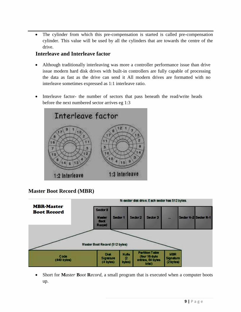
Interleave and Interleave factor
Although traditionally interleaving was more a controller performance issue than drive
issue modern hard disk drives with built-in controllers are fully capable of processing
the data as fast as the drive can send it All modern drives are formatted with no
interleave sometimes expressed as 1:1 interleave ratio.
Interleave factor- the number of sectors that pass beneath the read/write heads
before the next numbered sector arrives eg 1:3
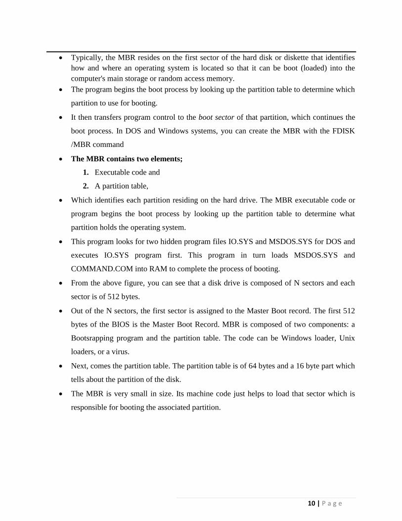
Master Boot Record (MBR)
Short for Master Boot Record, a small program that is executed when a computer boots
up.
10 | P a g e
Typically, the MBR resides on the first sector of the hard disk or diskette that identifies
how and where an operating system is located so that it can be boot (loaded) into the
computer's main storage or random access memory.
The program begins the boot process by looking up the partition table to determine which
partition to use for booting.
It then transfers program control to the boot sector of that partition, which continues the
boot process. In DOS and Windows systems, you can create the MBR with the FDISK
/MBR command
The MBR contains two elements;
1. Executable code and
2. A partition table,
Which identifies each partition residing on the hard drive. The MBR executable code or
program begins the boot process by looking up the partition table to determine what
partition holds the operating system.
This program looks for two hidden program files IO.SYS and MSDOS.SYS for DOS and
executes IO.SYS program first. This program in turn loads MSDOS.SYS and
COMMAND.COM into RAM to complete the process of booting.
From the above figure, you can see that a disk drive is composed of N sectors and each
sector is of 512 bytes.
Out of the N sectors, the first sector is assigned to the Master Boot record. The first 512
bytes of the BIOS is the Master Boot Record. MBR is composed of two components: a
Bootsrapping program and the partition table. The code can be Windows loader, Unix
loaders, or a virus.
Next, comes the partition table. The partition table is of 64 bytes and a 16 byte part which
tells about the partition of the disk.
The MBR is very small in size. Its machine code just helps to load that sector which is
responsible for booting the associated partition.
11 | P a g e
Servo Techniques
There are three different ways that the hard disk servo mechanism has been implemented.
Wedge Servo, Dedicated Servo, Embedded Servo
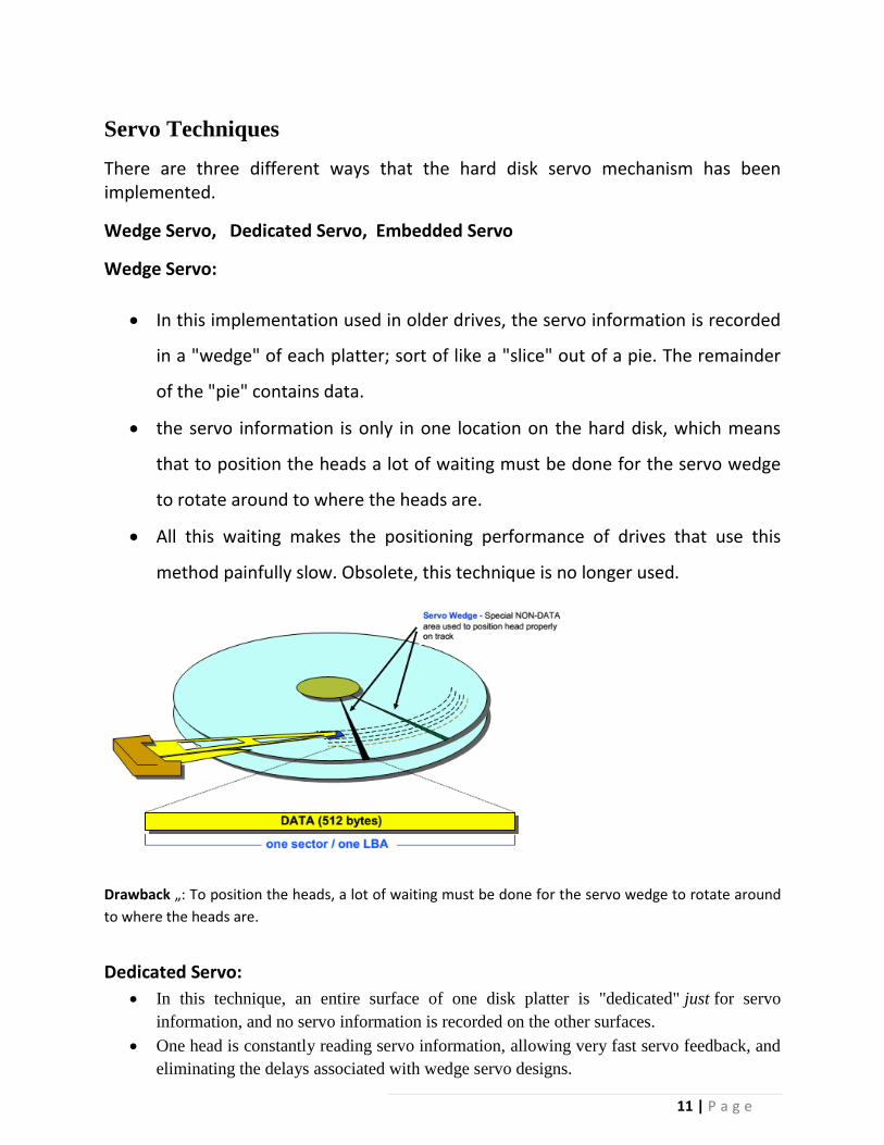
Wedge Servo:
In this implementation used in older drives, the servo information is recorded
in a "wedge" of each platter; sort of like a "slice" out of a pie. The remainder
of the "pie" contains data.
the servo information is only in one location on the hard disk, which means
that to position the heads a lot of waiting must be done for the servo wedge
to rotate around to where the heads are.
All this waiting makes the positioning performance of drives that use this
method painfully slow. Obsolete, this technique is no longer used.
Drawback „: To position the heads, a lot of waiting must be done for the servo wedge to rotate around
to where the heads are.
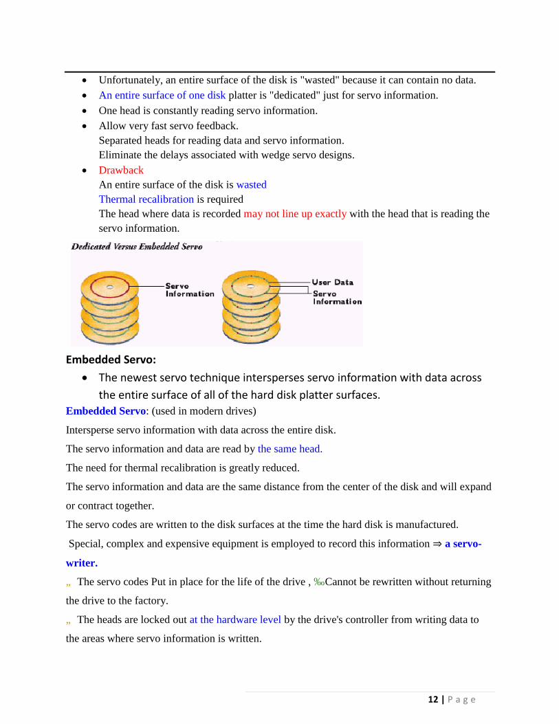
Dedicated Servo:
In this technique, an entire surface of one disk platter is "dedicated" just for servo
information, and no servo information is recorded on the other surfaces.
One head is constantly reading servo information, allowing very fast servo feedback, and
eliminating the delays associated with wedge servo designs.
12 | P a g e
Unfortunately, an entire surface of the disk is "wasted" because it can contain no data.
An entire surface of one disk platter is "dedicated" just for servo information.
One head is constantly reading servo information.
Allow very fast servo feedback.
Separated heads for reading data and servo information.
Eliminate the delays associated with wedge servo designs.
Drawback
An entire surface of the disk is wasted
Thermal recalibration is required
The head where data is recorded may not line up exactly with the head that is reading the
servo information.
Embedded Servo:
The newest servo technique intersperses servo information with data across
the entire surface of all of the hard disk platter surfaces.
Embedded Servo: (used in modern drives)
Intersperse servo information with data across the entire disk.
The servo information and data are read by the same head.
The need for thermal recalibration is greatly reduced.
The servo information and data are the same distance from the center of the disk and will expand
or contract together.
The servo codes are written to the disk surfaces at the time the hard disk is manufactured.
Special, complex and expensive equipment is employed to record this information ⇒ a servo-
writer.
„ The servo codes Put in place for the life of the drive , ‰ Cannot be rewritten without returning
the drive to the factory.
„ The heads are locked out at the hardware level by the drive's controller from writing data to
the areas where servo information is written.
13 | P a g e
Formatting What is formatting? Explain low level and high level formatting. Formatting (1 M)
1. It prepares a blank hard disk for a particular OS.
2. It puts magnetic marks of tracks and sectors on the platter surface.
3. The storage capacity of formatted hard disk is always less than the capacity of
unformatted disk.
4. A typical sector has 3 standard components.
a. Identification field which contains the address of the sector i.e. the track head and the sector
number.
b. Data field which contains data recorded at a particular location. It also contains error detection
and correction codes.
c. Number of gaps.
FAT and root directory are also put on the platter at the time of formatting. Hard Disk requires a
low level formatting and a high level formatting to make it useful for data storage
Low Level Formatting (Physical or true formatting) (1 ½ M)
1. It is done at the factory level. (In low level formatting all the data stored on the disk is
lost as the disk is physically formatted)
2. It magnetically divides the disk into tracks and sector.
3. Basic addressing information is written to each sector of each cylinder.
3. It checks for bad sectors and maps them out.
High Level Formatting (1 ½ M)
1. It is done with the help of OS.
2. High level Format program scans the disk for tracks and sectors marked bad during low
level formatting. The scanning program performs five retries to read the tracks or sectors.
If the tracks are still unreadable, the area is noted as bad cluster in FAT.
3. After scanning the entire disk, the drive heads return to the first sector of the partition and
write MBR. Immediately in the next sector 1st copy of FAT is written and after that 2nd
14 | P a g e
copy of FAT is written. Initially FATS are blank except for the bad cluster marks found
in the initial scan.
4. After the 2nd copy of FAT blank root directory is created.
What is FAT? List two features of FAT 32. (1 M each)
The file system in storage devices starts with FAT (File allocation Table).
1. FAT refers to a data table that holds information about how and where files are stored in any
partition
2. It is a kind of index used by operating system to keep track of information stored on the hard
disk
FAT 32 (Any Two)
1. Introduced with Microsoft windows 95, supports drives up to 2 TB
2. Since it can space more efficiently, it uses smaller clusters( 4 KB clusters for drives up to
8 GB) fetch
3. No compression or encryption available on FAT 32 file system
Partitioning
Creating a partition on a hard disk drive enables it to support file systems each in its own
partition. Three common file systems are used by PC operating today:/
FAT (File Allocation Table)
1. Developed by Microsoft for MS-DOS, MS-Windows 95,98,Me
2. FAT located in MBR sector of bootable disk
3. 2 Important Functions of FAT;
4. contains allocation information (in the form of linked list)
5. Indicate which allocation units are free.
6. It is simple and reliable. Two identical copies of FAT are used.
Structure of FAT
Partition FAT 1 FAT 2 Root Folder Other
Boot Sector (Duplicate) Folders and All Files
15 | P a g e
NTFS (New Technology File System)
Structure
Partition Boot Master File System File File Area
Sector Table
1. Used by Windows NT, XP, 2000 , Server 2003, Server 2008, Windows Vista
2. NTFS provides better performance, security compatibility and extendibility than
FAT
3. Read, Search, Write, Recovery are done fast.
4. Master File Table (MFT) contain information about all files and folders. First file on
NTFS volume.
5. Partition Boot Sector Start at Sector 0 to 16. First Info on an NTFS volume.
Features
1. It allows you to encrypt files and automatically decrypt them as they are read.
2. Supports long file names upto 255 characters
3. Supports File Size upto 2 TB
4. For keeping track of clusters it uses a B- tree directory
5. Reliable File System as compared to FAT
6. Allows Large partition sizes i.e more than 4 GB
7. Built-in file compression facility
8. Improved Security And access control deciding who can perform what sorts of operations
on various data within the file system
Compare FAT 16, FAT 32, NTFS (Any four points – 1 mark each)
Criteria NTFS FAT 32 FAT16
OS Windows 2000, XP,
2003 server
DOS V7, Win
2000,98,XP
Dos , All version of
Windows
Maximum Vol Size 2TB 32GB 2GB
Max. Files on Vol Unlimited 4194304 65536
Max file size Limited by vol size 4GB 2 GB
Max Cluster number Unlimited 4177918 65524
Boot sector
location
1st and last First sector and
copy in sector No 6
First sector
Compression Yes NO NO
Built in security Yes NO NO
Recoverability Yes NO NO
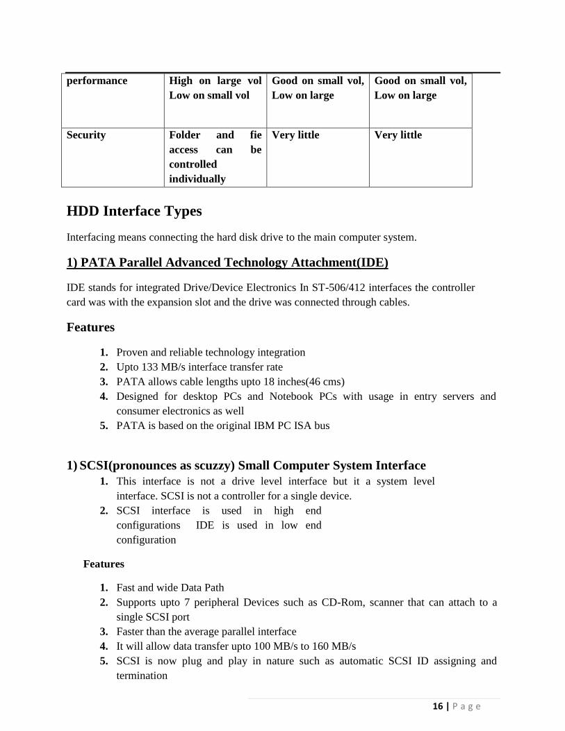
16 | P a g e
performance High on large vol
Low on small vol
Good on small vol,
Low on large
Good on small vol,
Low on large
Security Folder and fie
access can be
controlled
individually
Very little Very little
HDD Interface Types
Interfacing means connecting the hard disk drive to the main computer system.
1) PATA Parallel Advanced Technology Attachment(IDE)
IDE stands for integrated Drive/Device Electronics In ST-506/412 interfaces the controller
card was with the expansion slot and the drive was connected through cables.
Features
1. Proven and reliable technology integration
2. Upto 133 MB/s interface transfer rate
3. PATA allows cable lengths upto 18 inches(46 cms)
4. Designed for desktop PCs and Notebook PCs with usage in entry servers and
consumer electronics as well
5. PATA is based on the original IBM PC ISA bus
1) SCSI(pronounces as scuzzy) Small Computer System Interface
1. This interface is not a drive level interface but it a system level
interface. SCSI is not a controller for a single device.
2. SCSI interface is used in high end
configurations IDE is used in low end
configuration
Features
1. Fast and wide Data Path
2. Supports upto 7 peripheral Devices such as CD-Rom, scanner that can attach to a
single SCSI port
3. Faster than the average parallel interface
4. It will allow data transfer upto 100 MB/s to 160 MB/s
5. SCSI is now plug and play in nature such as automatic SCSI ID assigning and
termination

17 | P a g e
2) SATA (Serial Advanced Technology Attachment)
- Is a computer bus primarily designed for transfer of data between a computer and mass storage
devices such as hard disk drives and optical drives.
Features
1. SATA is better more efficient interface than the dated PATA standard.
2. It supports hot swapping
3. Serial ATA uses only 7 conductors while PATA uses 40.
4. Data Transfers at the rate of 1.5 Gbit/s, 3 Gbit/s and 6 Gbit/s
CD ROM Recording
Explain working of CD-ROM drive with block diagram. (2 Diagram; 2 M working)
Fig: Block Diagram of CDROM drive
1. The laser diode emits a low –energy infra red beam towards the reflecting mirror
2. The servo motor positions the beam onto the correct track on the CD ROM by
moving the reflecting mirror
3. When the beam hits the disc, its reflected light is gathered and focused through the
first lens beneath the platter, bounce off the mirror and sent towards the beam splitter
4. The beam splitter directs the returning laser light towards another focusing lens
5. The last lens direct the light beam to a photo detector and convert the light into
electric impulses
These incoming impulses are decoded by the microprocessor and sent along to the host computer
as data
18 | P a g e
Recording of CDROM Drive
- EFM (Eight to Fourteen Modulation) is an encoding technique used by CDs and
provides a way of countering errors by encoding a byte into 2 bytes.
- Using EFM data is broken into 8 bit blocks(bytes)
- Each 8 bit block is translated into a corresponding 14 bit codeword using a predefined
lookup table.
Digital Versatile Disc
1. Optional storage media for storing data
2. Uses primary for movies softwares and data backup purpose
3. DVD holds about 7 times more data than CD Data
4. DVDs can store more data than CDs for a few reasons:
Higher-density data storage
Less overhead, more area
Multi-layer storage
Comparison of CD and DVD
Parameter CD DVD Remarks
Sides 1 1 or 2
Layers 1 1 or 2
Capacity (GB) 0.68 GB 4.7-17 GB
Track pitch(µ) 1.6 0.74
Minimum pit 0.83 0.4
length(µ)
Wavelength(nm) 780 650 Of laser diode
pickup
19 | P a g e
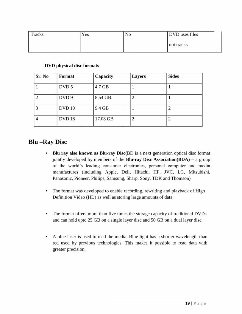
Tracks Yes No DVD uses files
not tracks
DVD physical disc formats
Sr. No Format Capacity Layers Sides
1 DVD 5 4.7 GB 1 1
2 DVD 9 8.54 GB 2 1
3 DVD 10 9.4 GB 1 2
4 DVD 18 17.08 GB 2 2
Blu –Ray Disc
• Blu ray also known as Blu-ray Disc(BD is a next generation optical disc format
jointly developed by members of the Blu-ray Disc Association(BDA) – a group
of the world’s leading consumer electronics, personal computer and media
manufactures (including Apple, Dell, Hitachi, HP, JVC, LG, Mitsubishi,
Panasonic, Pioneer, Philips, Samsung, Sharp, Sony, TDK and Thomson)
• The format was developed to enable recording, rewriting and playback of High
Definition Video (HD) as well as storing large amounts of data.
• The format offers more than five times the storage capacity of traditional DVDs
and can hold upto 25 GB on a single layer disc and 50 GB on a dual layer disc.
• A blue laser is used to read the media. Blue light has a shorter wavelength than
red used by previous technologies. This makes it possible to read data with
greater precision.
20 | P a g e
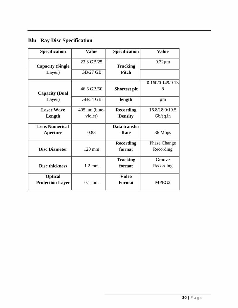
Blu –Ray Disc Specification
Specification Value Specification Value
Capacity (Single
Layer)
23.3 GB/25 Tracking
Pitch
0.32µm
GB/27 GB
Capacity (Dual
Layer)
46.6 GB/50 Shortest pit
0.160/0.149/0.13
8
GB/54 GB length µm
Laser Wave
Length
405 nm (blue-
violet)
Recording
Density
16.8/18.0/19.5
Gb/sq.in
Lens Numerical
Aperture 0.85
Data transfer
Rate 36 Mbps
Disc Diameter 120 mm
Recording
format
Phase Change
Recording
Disc thickness 1.2 mm
Tracking
format
Groove
Recording
Optical
Protection Layer 0.1 mm
Video
Format MPEG2