Embed Size (px)
Citation preview
INSTRUCTION MANUALCOMPUTERIZED TONOMETER
CT-80
INTRODUCTIONThank you for purchasing the TOPCON Computer-ized Tonometer CT-80.(To get the best use from the instrument, please carefullyread these instructions and keep this Instruction Manual in aconvenient location for future reference.)
This instrument features the following:• An exact, non-contact intraocular pressure measurement that
can be done by air ejection.• An alignment bar that enables easy operation.
This text outlines the Computerized Tonometer CT-80 and de-scribes basic operations, troubleshooting, checking, maintenanceand cleaning.To encourage the safe, efficient use of this instrument and preventdanger to the operator and others, we suggest you carefully readthe “Displays for Safe Use” and the “Safety Cautions”.Again, please keep this Instruction Manual in a convenient locationfor future reference.
Precautions• This machine is a precision instrument; install it in a place set to the fol-
lowing conditions: temperature (10∼60°C), humidity (30∼85%) and atmos-pheric pressure (70∼106KPa). Avoid direct exposure to sunlight.
• To ensure smooth operation, install the instrument on a level place free ofvibrations. Also, do not place any objects on the instrument.
• Before using the instrument, connect all cables correctly.• Use the specified source voltage.• When not in use, turn the power off and put the measuring window cap and
dust cover on.• To ensure a correct reading, do not soil the measuring window with finger
prints, dust, etc. Also, do not touch the measuring nozzle except whencleaning.
1
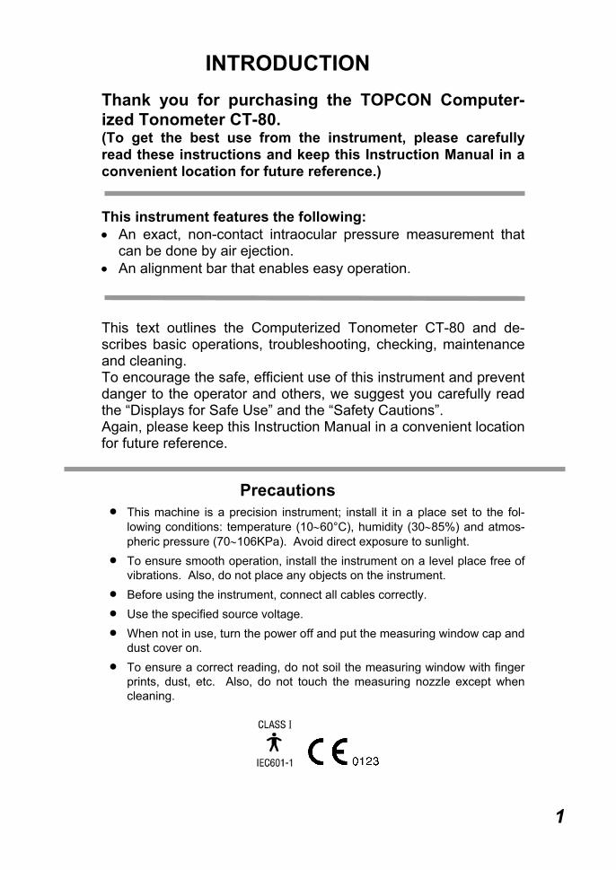
DISPLAY FOR SAFE USEIn order to encourage the safe use of the product and prevent any danger to the operator andothers or damage to properties, important warnings are placed on the product and inserted in theinstruction manual.We suggest that everyone understand the meaning of the following displays and icons beforereading the “Safety Cautions” and text.
• Injury refers to cuts, bruises, sprains, fractures, burn, electric shock, etc.• Physical damage refers to extensive damage to buildings or equipment and furniture.
This icon indicates Hazard Alerting (Warning).Prohibition.Specific content is expressed with words or an icon either insert-ed in the icon itself or located next to the icon.
This indicates Prohibition.Specific content is expressed with words or an icon either insert-ed in the icon itself or located next to the icon.
This indicates Mandatory Action.Specific content is expressed with words or an icon either insert-ed in the icon itself or located next to the icon.
2
DISPLAY
ICONS MEANING
WARNING
CAUTION
MEANING
Ignoring or disregarding this display may lead todeath or serious injury.
Ignoring or disregarding this display may lead topersonal injury or physical damage.
SAFETY CAUTIONS
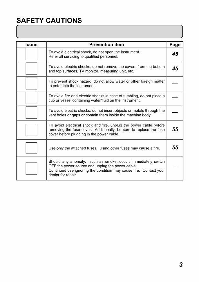
Icons Prevention item PageTo avoid electrical shock, do not open the instrument.Refer all servicing to qualified personnel. 45
To avoid electric shocks, do not remove the covers from the bottomand top surfaces, TV monitor, measuring unit, etc. 45
To prevent shock hazard, do not allow water or other foreign matterto enter into the instrument. —
To avoid fire and electric shocks in case of tumbling, do not place acup or vessel containing water/fluid on the instrument. —
To avoid electric shocks, do not insert objects or metals through thevent holes or gaps or contain them inside the machine body. —
To avoid electrical shock and fire, unplug the power cable beforeremoving the fuse cover. Additionally, be sure to replace the fusecover before plugging in the power cable.
55
Use only the attached fuses. Using other fuses may cause a fire. 55
Should any anomaly, such as smoke, occur, immediately switchOFF the power source and unplug the power cable.Continued use ignoring the condition may cause fire. Contact yourdealer for repair.
—
WARNING
3
SAFETY CAUTIONS
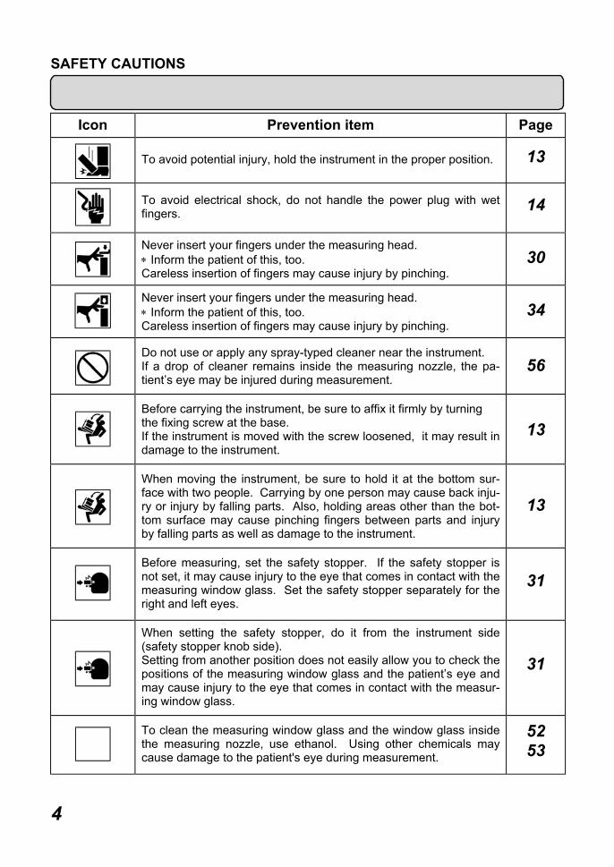
Icon Prevention item Page
To avoid potential injury, hold the instrument in the proper position. 13
To avoid electrical shock, do not handle the power plug with wetfingers. 14
Never insert your fingers under the measuring head.∗ Inform the patient of this, too.Careless insertion of fingers may cause injury by pinching.
30
Never insert your fingers under the measuring head.∗ Inform the patient of this, too.Careless insertion of fingers may cause injury by pinching.
34
Do not use or apply any spray-typed cleaner near the instrument.If a drop of cleaner remains inside the measuring nozzle, the pa-tient’s eye may be injured during measurement.
56
Before carrying the instrument, be sure to affix it firmly by turningthe fixing screw at the base.If the instrument is moved with the screw loosened, it may result indamage to the instrument.
13
When moving the instrument, be sure to hold it at the bottom sur-face with two people. Carrying by one person may cause back inju-ry or injury by falling parts. Also, holding areas other than the bot-tom surface may cause pinching fingers between parts and injuryby falling parts as well as damage to the instrument.
13
Before measuring, set the safety stopper. If the safety stopper isnot set, it may cause injury to the eye that comes in contact with themeasuring window glass. Set the safety stopper separately for theright and left eyes.
31
When setting the safety stopper, do it from the instrument side(safety stopper knob side).Setting from another position does not easily allow you to check thepositions of the measuring window glass and the patient’s eye andmay cause injury to the eye that comes in contact with the measur-ing window glass.
31
To clean the measuring window glass and the window glass insidethe measuring nozzle, use ethanol. Using other chemicals maycause damage to the patient's eye during measurement.
5253
CAUTION
4
USAGE AND MAINTENANCEPURPOSE
This tonometer “CT-80” is a precision electrical device for medical use that must beused under the instruction of a doctor.
USER MAINTENANCETo maintain the safety and performance of the equipment, never attempt to do mainte-nance on your own. Ask our serviceman for repair except for the items specified herewhich can be maintained by the user. For details, follow the instructions.
Fuse replacementThe primary fuses for the main body may be replaced by a non-trained service techni-cian. For details, refer to “Replacing the Fuse” on page 55.
Cleaning of measuring windowCleaning of the measuring window glass is possible. For details, refer to the instruc-tions in “Cleaning the Measuring Window Glass” on page 52.
Cleaning of window inside the nozzleCleaning of the window inside the nozzle is possible by following the instruction in“Cleaning the Window Glass inside the Nozzle” on page 53.
ESCAPE CLAUSE• TOPCON shall not take any responsibility for damage due to fire, earthquakes, actions
by a third party or other accidents, or the negligence and misuse of the user and use un-der unusual conditions.
• TOPCON shall not take any responsibility for damage derived from the inability to usethis equipment, such as a loss of business profit and suspension of business.
• TOPCON shall not take any responsibility for damage caused by operations other thanthose described in this Instruction Manual.
• Diagnoses shall be made on the responsibility of pertaining doctors and TOPCON shallnot take any responsibility for the results of such diagnoses.
5
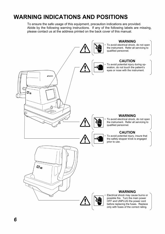
WARNING INDICATIONS AND POSITIONSTo ensure the safe usage of this equipment, precaution indications are provided.Abide by the following warning instructions. If any of the following labels are missing,please contact us at the address printed on the back cover of this manual.
6
WARNING• To avoid electrical shock, do not open
the instrument. Refer all servicing toqualified personnel.
CAUTION• To avoid potential injury, insure that
the safety stopper knob is engagedprior to use.
CAUTION• To avoid potential injury during op-
eration, do not touch the patient’seyes or nose with the instrument.
WARNING• To avoid electrical shock, do not open
the instrument. Refer all servicing toqualified personnel.
WARNING• Electrical shock may cause burns or
possible fire. Turn the main powerOFF and UNPLUG the power cordbefore replacing the fuses. Replaceonly with fuses of the correct rating.
CONTENT
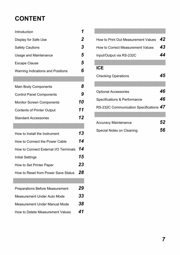
Introduction 1Display for Safe Use 2Safety Cautions 3Usage and Maintenance 5Escape Clause 5Warning Indications and Positions 6NAMES OF COMPONENTSMain Body Components 8Control Panel Components 9Monitor Screen Components 10Contents of Printer Output 11Standard Accessories 12PREPARATIONSHow to Install the Instrument 13How to Connect the Power Cable 14How to Connect External I/O Terminals 14Initial Settings 15How to Set Printer Paper 23How to Reset from Power Save Status 28BASIC OPERATIONSPreparations Before Measurement 29Measurement Under Auto Mode 33Measurement Under Manual Mode 38How to Delete Measurement Values 41
INDIVIDUAL OPERATIONSHow to Print Out Measurement Values 42How to Correct Measurement Values 43Input/Output via RS-232C 44BEFORE REQUESTING SERV-ICEChecking Operations 45REFERENCEOptional Accessories 46Specifications & Performance 46RS-232C Communication Specifications 47MAINTENANCE AND CHECKINGAccuracy Maintenance 52Special Notes on Cleaning 56
7
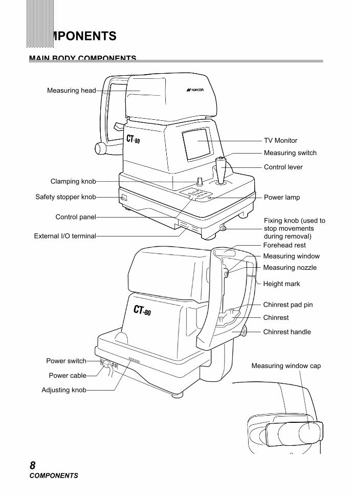
COMPONENTSMAIN BODY COMPONENTS
8COMPONENTS
Measuring window cap
Measuring head
Clamping knob
Safety stopper knob
Control panel
External I/O terminal
TV Monitor
Measuring switch
Control lever
Power lamp
Fixing knob (used to stop movements during removal)
Power switch
Power cable
Adjusting knob
Forehead rest Measuring window Measuring nozzle
Height mark
Chinrest pad pin
Chinrest
Chinrest handle
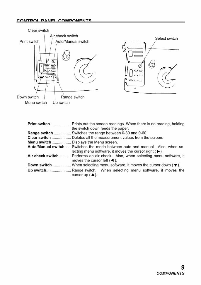
CONTROL PANEL COMPONENTS
Print switch ................... Prints out the screen readings. When there is no reading, holdingthe switch down feeds the paper.
Range switch ................ Switches the range between 0-30 and 0-60.Clear switch .................. Deletes all the measurement values from the screen.Menu switch .................. Displays the Menu screen.Auto/Manual switch...... Switches the mode between auto and manual. Also, when se-
lecting menu software, it moves the cursor right ( ).Air check switch ........... Performs an air check. Also, when selecting menu software, it
moves the cursor left ( ).Down switch ................. When selecting menu software, it moves the cursor down ( ).Up switch....................... Range switch. When selecting menu software, it moves the
cursor up ( ).
9COMPONENTS
Print switch Auto/Manual switch
Clear switchAir check switch
Down switch Range switchMenu switch Up switch
Select switch
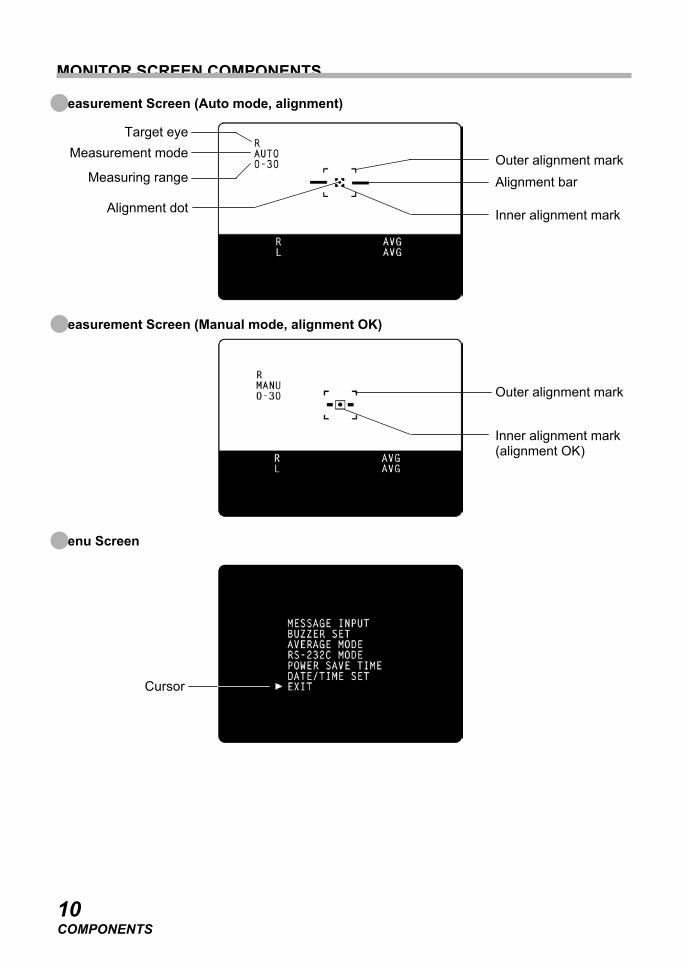
MONITOR SCREEN COMPONENTS
Measurement Screen (Auto mode, alignment)
Measurement Screen (Manual mode, alignment OK)
Menu Screen
10COMPONENTS
Inner alignment mark
Outer alignment mark Alignment bar
Alignment dot
Measuring range
Measurement modeTarget eye
Inner alignment mark (alignment OK)
Outer alignment mark
Cursor
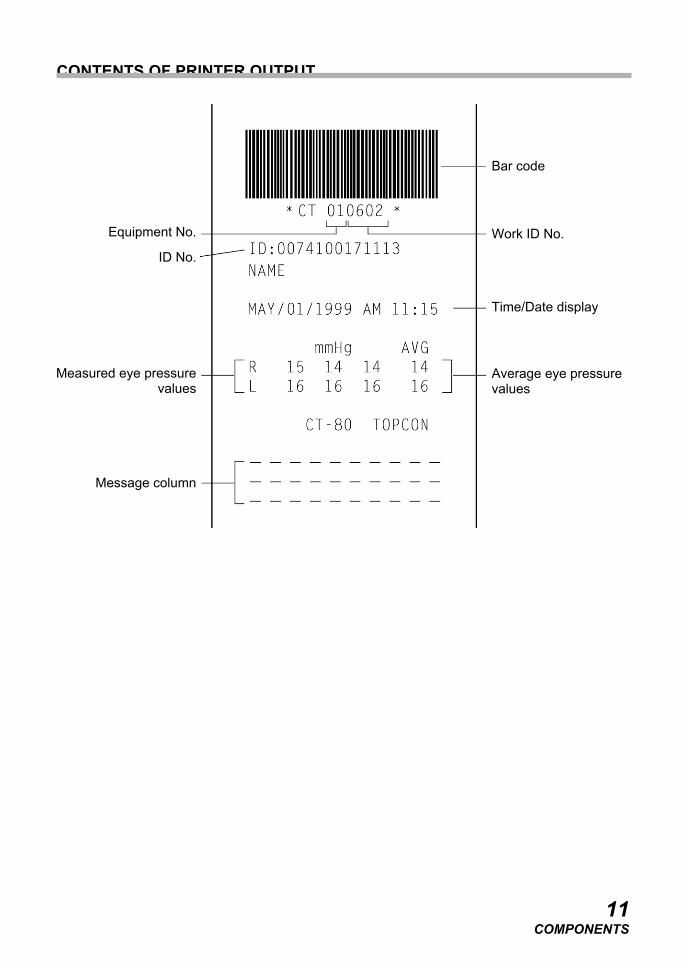
CONTENTS OF PRINTER OUTPUT
11COMPONENTS
Average eye pressurevalues
Time/Date display
Work ID No.
Message column
Measured eye pressurevalues
ID No.
Equipment No.
Bar code
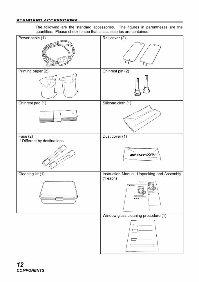
STANDARD ACCESSORIESThe following are the standard accessories. The figures in parentheses are thequantities. Please check to see that all accessories are contained.
Power cable (1) Rail cover (2)
Printing paper (2) Chinrest pin (2)
Chinrest pad (1) Silicone cloth (1)
Fuse (2) * Different by destinations
Dust cover (1)
Cleaning kit (1) Instruction Manual, Unpacking and Assembly(1 each)
Window glass cleaning procedure (1)
12COMPONENTS
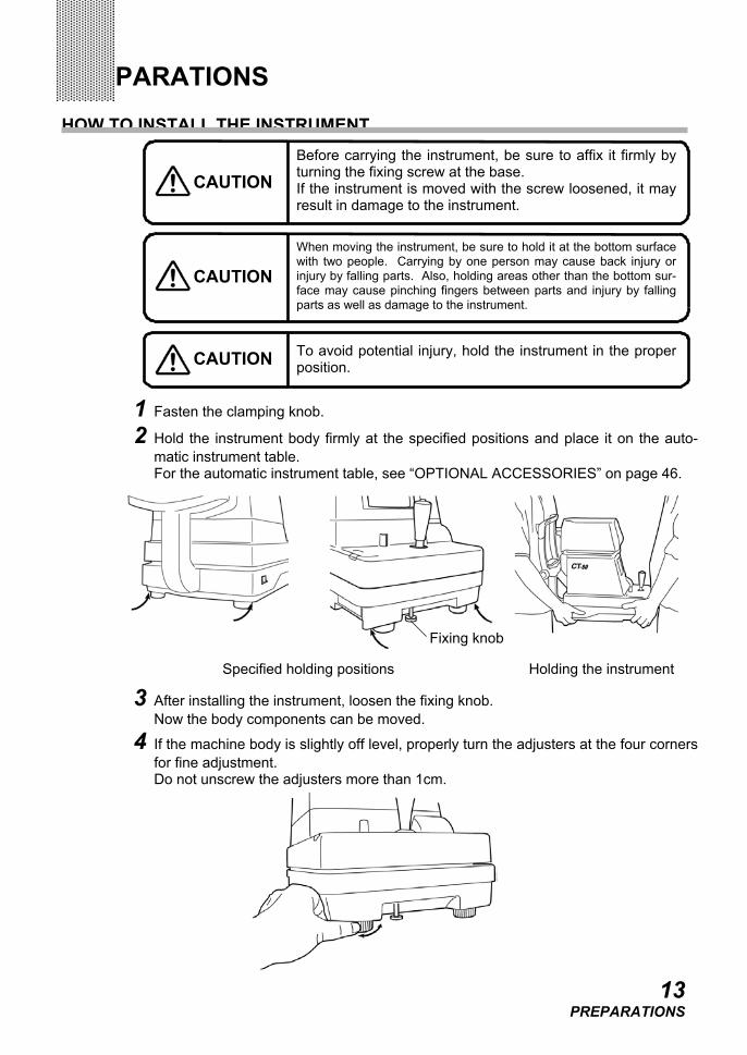
PREPARATIONSHOW TO INSTALL THE INSTRUMENT
1 Fasten the clamping knob.
2 Hold the instrument body firmly at the specified positions and place it on the auto-matic instrument table.For the automatic instrument table, see “OPTIONAL ACCESSORIES” on page 46.
3 After installing the instrument, loosen the fixing knob.Now the body components can be moved.
4 If the machine body is slightly off level, properly turn the adjusters at the four cornersfor fine adjustment.Do not unscrew the adjusters more than 1cm.
13PREPARATIONS
Before carrying the instrument, be sure to affix it firmly byturning the fixing screw at the base.If the instrument is moved with the screw loosened, it mayresult in damage to the instrument.
CAUTION
When moving the instrument, be sure to hold it at the bottom surfacewith two people. Carrying by one person may cause back injury orinjury by falling parts. Also, holding areas other than the bottom sur-face may cause pinching fingers between parts and injury by fallingparts as well as damage to the instrument.
CAUTION
To avoid potential injury, hold the instrument in the properposition.CAUTION
Holding the instrumentSpecified holding positions
Fixing knob
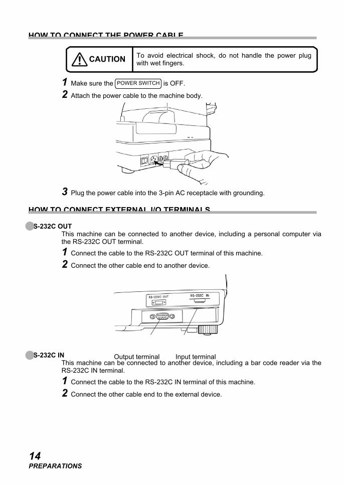
HOW TO CONNECT THE POWER CABLE
1 Make sure the POWER SWITCH is OFF.
2 Attach the power cable to the machine body.
3 Plug the power cable into the 3-pin AC receptacle with grounding.
HOW TO CONNECT EXTERNAL I/O TERMINALS
RS-232C OUTThis machine can be connected to another device, including a personal computer viathe RS-232C OUT terminal.
1 Connect the cable to the RS-232C OUT terminal of this machine.
2 Connect the other cable end to another device.
RS-232C INThis machine can be connected to another device, including a bar code reader via theRS-232C IN terminal.
1 Connect the cable to the RS-232C IN terminal of this machine.
2 Connect the other cable end to the external device.
14PREPARATIONS
To avoid electrical shock, do not handle the power plugwith wet fingers.CAUTION
Input terminalOutput terminal
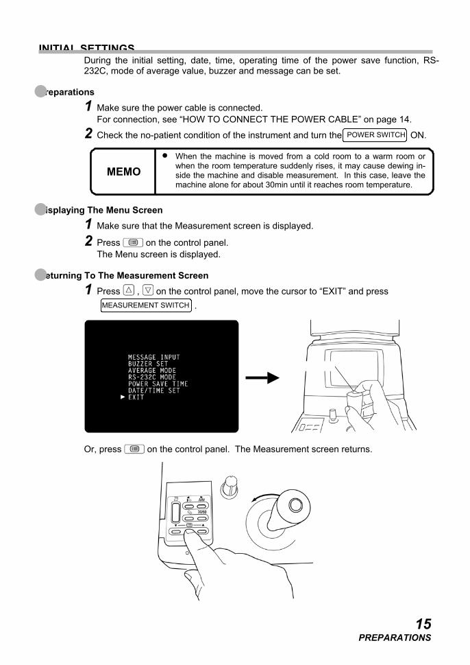
INITIAL SETTINGSDuring the initial setting, date, time, operating time of the power save function, RS-232C, mode of average value, buzzer and message can be set.
Preparations1 Make sure the power cable is connected.
For connection, see “HOW TO CONNECT THE POWER CABLE” on page 14.
2 Check the no-patient condition of the instrument and turn the POWER SWITCH ON.
Displaying The Menu Screen1 Make sure that the Measurement screen is displayed.
2 Press on the control panel.The Menu screen is displayed.
Returning To The Measurement Screen1 Press , on the control panel, move the cursor to “EXIT” and press
MEASUREMENT SWITCH .
Or, press on the control panel. The Measurement screen returns.
15PREPARATIONS
• When the machine is moved from a cold room to a warm room orwhen the room temperature suddenly rises, it may cause dewing in-side the machine and disable measurement. In this case, leave themachine alone for about 30min until it reaches room temperature.
MEMO
Measurement switch
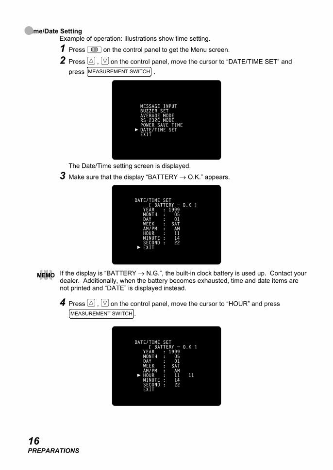
Time/Date SettingExample of operation: Illustrations show time setting.
1 Press on the control panel to get the Menu screen.
2 Press , on the control panel, move the cursor to “DATE/TIME SET” andpress MEASUREMENT SWITCH .
The Date/Time setting screen is displayed.
3 Make sure that the display “BATTERY → O.K.” appears.
4 Press , on the control panel, move the cursor to “HOUR” and press MEASUREMENT SWITCH .
16PREPARATIONS
If the display is “BATTERY → N.G.”, the built-in clock battery is used up. Contact yourdealer. Additionally, when the battery becomes exhausted, time and date items arenot printed and “DATE” is displayed instead.
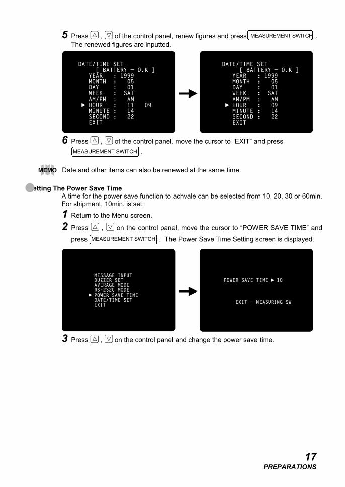
5 Press , of the control panel, renew figures and press MEASUREMENT SWITCH .The renewed figures are inputted.
6 Press , of the control panel, move the cursor to “EXIT” and press MEASUREMENT SWITCH .
Setting The Power Save TimeA time for the power save function to achvale can be selected from 10, 20, 30 or 60min.For shipment, 10min. is set.
1 Return to the Menu screen.
2 Press , on the control panel, move the cursor to “POWER SAVE TIME” and
press MEASUREMENT SWITCH . The Power Save Time Setting screen is displayed.
3 Press , on the control panel and change the power save time.
17PREPARATIONS
Date and other items can also be renewed at the same time.
4 Press MEASUREMENT SWITCH . The Menu screen is displayed.
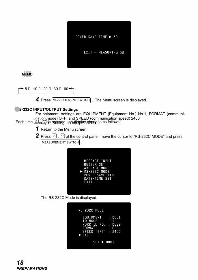
RS-232C INPUT/OUTPUT SettingsFor shipment, settings are EQUIPMENT (Equipment No.) No.1, FORMAT (communi-cation mode) OFF, and SPEED (communication speed) 2400Example: Setting the equipment No.
1 Return to the Menu screen.
2 Press , of the control panel, move the cursor to “RS-232C MODE” and press MEASUREMENT SWITCH .
The RS-232C Mode is displayed.
18PREPARATIONS
Each time , is pressed, the display changes as follows:
5 ↔ 10 ↔ 20 ↔ 30 ↔ 60
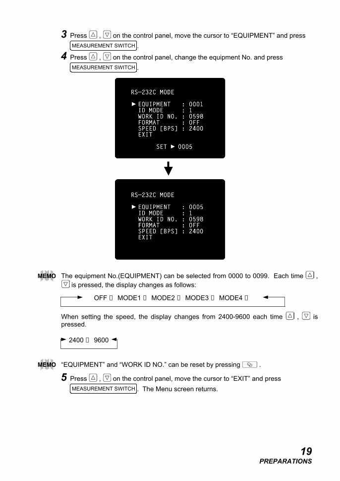
3 Press , on the control panel, move the cursor to “EQUIPMENT” and press MEASUREMENT SWITCH .
4 Press , on the control panel, change the equipment No. and press MEASUREMENT SWITCH .
5 Press , on the control panel, move the cursor to “EXIT” and press MEASUREMENT SWITCH . The Menu screen returns.
19PREPARATIONS
“EQUIPMENT” and “WORK ID NO.” can be reset by pressing .
The equipment No.(EQUIPMENT) can be selected from 0000 to 0099. Each time , is pressed, the display changes as follows:
When setting the speed, the display changes from 2400-9600 each time , ispressed.
OFF ↔ MODE1 ↔ MODE2 ↔ MODE3 ↔ MODE4 ↔
2400 ↔ 9600
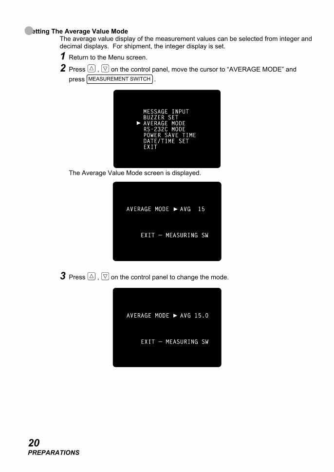
Setting The Average Value ModeThe average value display of the measurement values can be selected from integer anddecimal displays. For shipment, the integer display is set.
1 Return to the Menu screen.
2 Press , on the control panel, move the cursor to “AVERAGE MODE” andpress MEASUREMENT SWITCH .
The Average Value Mode screen is displayed.
3 Press , on the control panel to change the mode.
20PREPARATIONS
4 Press MEASUREMENT SWITCH . The Menu screen returns.
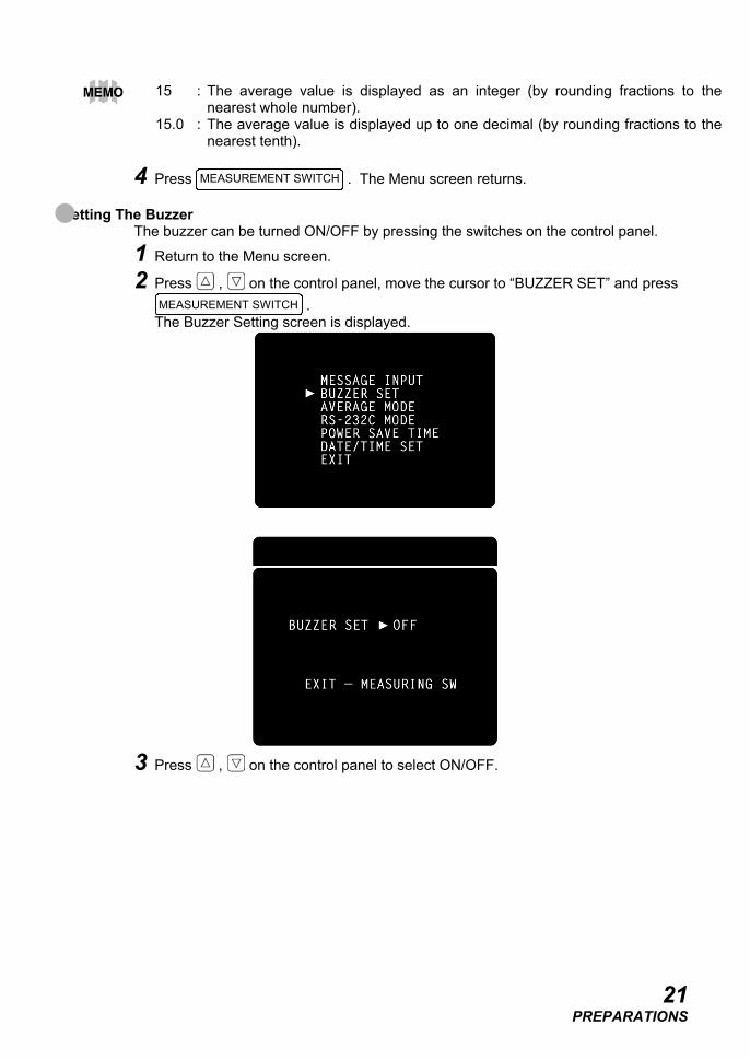
Setting The BuzzerThe buzzer can be turned ON/OFF by pressing the switches on the control panel.
1 Return to the Menu screen.
2 Press , on the control panel, move the cursor to “BUZZER SET” and press MEASUREMENT SWITCH .The Buzzer Setting screen is displayed.
3 Press , on the control panel to select ON/OFF.
21PREPARATIONS
15 : The average value is displayed as an integer (by rounding fractions to thenearest whole number).
15.0 : The average value is displayed up to one decimal (by rounding fractions to thenearest tenth).
4 Press MEASUREMENT SWITCH .The Menu screen returns.
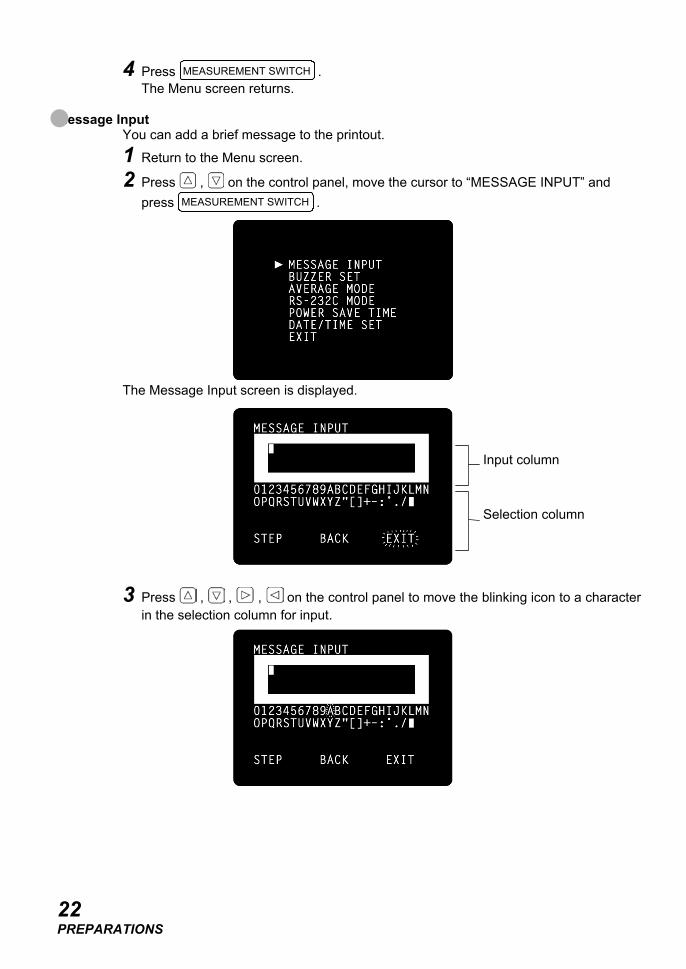
Message InputYou can add a brief message to the printout.
1 Return to the Menu screen.
2 Press , on the control panel, move the cursor to “MESSAGE INPUT” andpress MEASUREMENT SWITCH .
The Message Input screen is displayed.
3 Press , , , on the control panel to move the blinking icon to a characterin the selection column for input.
22PREPARATIONS
Selection column
Input column

4 Press MEASUREMENT SWITCH .The character selected by the blinking icon is inputted.
5 Press , , , on the control panel, move the blinking icon in the selection
column to “EXIT” and press MEASUREMENT SWITCH .The Menu screen is displayed.
HOW TO SET PRINTER PAPER
Auto Setting1 Press the printer cover with your thumb, slide it aside and remove.
23PREPARATIONS
■ : A space for 1 character (Use this to delete a character, too.)STEP : The blinking icon of the input column moves right.BACK : The blinking icon of the input column moves left.
When the right/left end is reached, the blinking icon goes down to the next line.A message can contain up to 3 lines, 20 characters per line.
Printer cover
2 Slide the paper roll onto the paper shaft, paying attention to the direction of unwind-ing, and pull out the top of the paper 7-8cm.
3 Insert the paper straight into the printer
along the paper guide.
4 When the top of the paper stops inside the printer, press to further insert thepaper into the printer.Paper feeding starts when the top of the paper reaches a certain depth inside theprinter.
5 When the top of the paper comes out 1cm or so from the outlet, release .At this moment, hold the top of the paper firmly so that it is not rolled back.
6 Turn the paper retainer lever to the illustrated position, and pull out the paper 2-3cmso that it comes out straight from the outlet.
24PREPARATIONS
Unwinding direction
Paper retainer lever
7 Return the paper retainer lever back to its original position.
8 Reset the printer cover, holding the top of the paper outside.
25PREPARATIONS
The paper is not fed unless the paper retainer lever is lowered.
Use the following 58mm wide printer paper:TF50KS-E2CUsing another paper may cause a printing noise or thin prints.
Manual Setting1 Press the printer cover with your thumb, slide it aside and remove.
2 Slide the paper roll onto the paper shaft, paying attention to the direction of unwind-ing, and pull out the top of the paper 7∼8cm.
3 Turn the paper retainer lever in the arrow direction.
4 Cut the paper on the control lever side at about 2cm.
26PREPARATIONS
Paper retainer lever
Control lever
Cut here
5 Insert the paper straight into the printer along the paper guide.
6 Further insert the paper and draw out the top of the paper from the outlet.
7 Adjust the paper so that it comes out straight from the outlet, and then lower the pa-per retainer lever.
27PREPARATIONS
The paper does not easily pass through the printer unless it is cut on the control leverside.
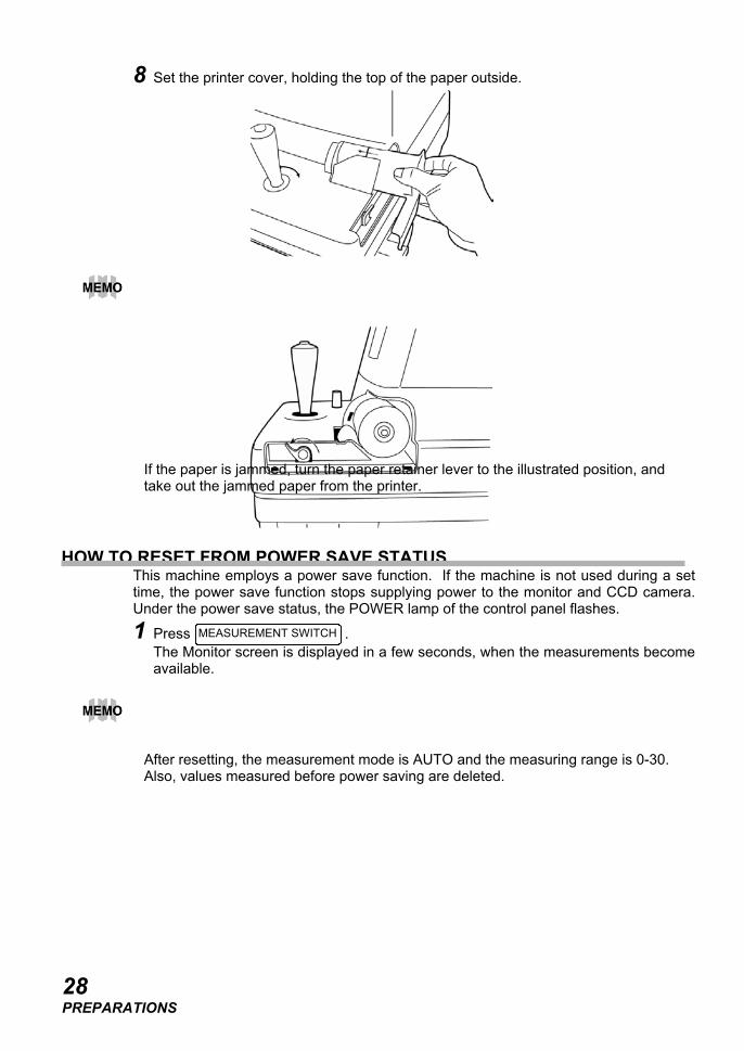
8 Set the printer cover, holding the top of the paper outside.
HOW TO RESET FROM POWER SAVE STATUSThis machine employs a power save function. If the machine is not used during a settime, the power save function stops supplying power to the monitor and CCD camera.Under the power save status, the POWER lamp of the control panel flashes.
1 Press MEASUREMENT SWITCH .The Monitor screen is displayed in a few seconds, when the measurements becomeavailable.
28PREPARATIONS
If the paper is jammed, turn the paper retainer lever to the illustrated position, andtake out the jammed paper from the printer.
After resetting, the measurement mode is AUTO and the measuring range is 0-30.Also, values measured before power saving are deleted.
BASIC OPERATIONSPREPARATIONS BEFORE MEASUREMENT
Turn ON the Power1 Make sure the power cable is connected.
For connection, see “HOW TO CONNECT THE POWER CABLE” on page 14.
2 Make sure the instrument is in the no-patient condition and turn ON the POWER SWITCH .
3 The Title screen is displayed, and then the Measurement screen is displayed.
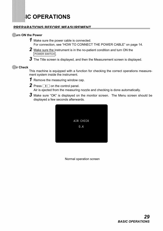
Air CheckThis machine is equipped with a function for checking the correct operations measure-ment system inside the instrument.
1 Remove the measuring window cap.
2 Press on the control panel.Air is ejected from the measuring nozzle and checking is done automatically.
3 Make sure “OK” is displayed on the monitor screen. The Menu screen should bedisplayed a few seconds afterwards.
29BASIC OPERATIONS
Normal operation screen
Setting the Patient
1 Return to the Measurement screen.
2 Ask the patient to sit in front of the instrument.
3 Adjust the automatic instrument table or the chair for height so that the patient canput his or her chin on the chinrest in a comfortable position.
4 The patient places his or her chin on the chinrest and stops his or her forehead atthe forehead rest.
30BASIC OPERATIONS
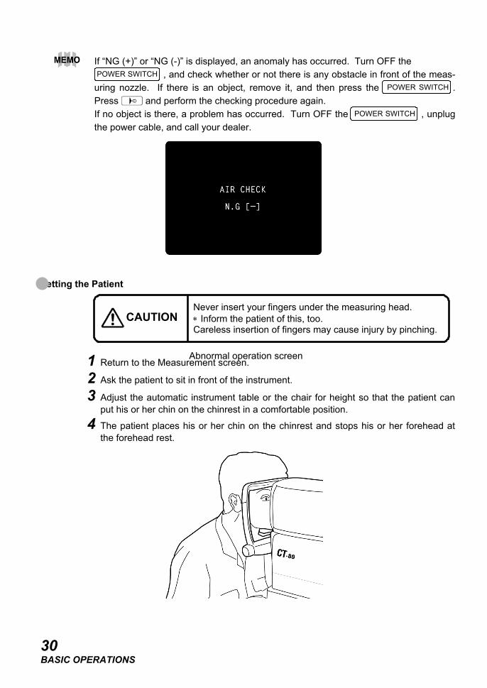
If “NG (+)” or “NG (-)” is displayed, an anomaly has occurred. Turn OFF the POWER SWITCH , and check whether or not there is any obstacle in front of the meas-uring nozzle. If there is an object, remove it, and then press the POWER SWITCH .Press and perform the checking procedure again.If no object is there, a problem has occurred. Turn OFF the POWER SWITCH , unplugthe power cable, and call your dealer.
Abnormal operation screen
Never insert your fingers under the measuring head.∗ Inform the patient of this, too.Careless insertion of fingers may cause injury by pinching.
CAUTION
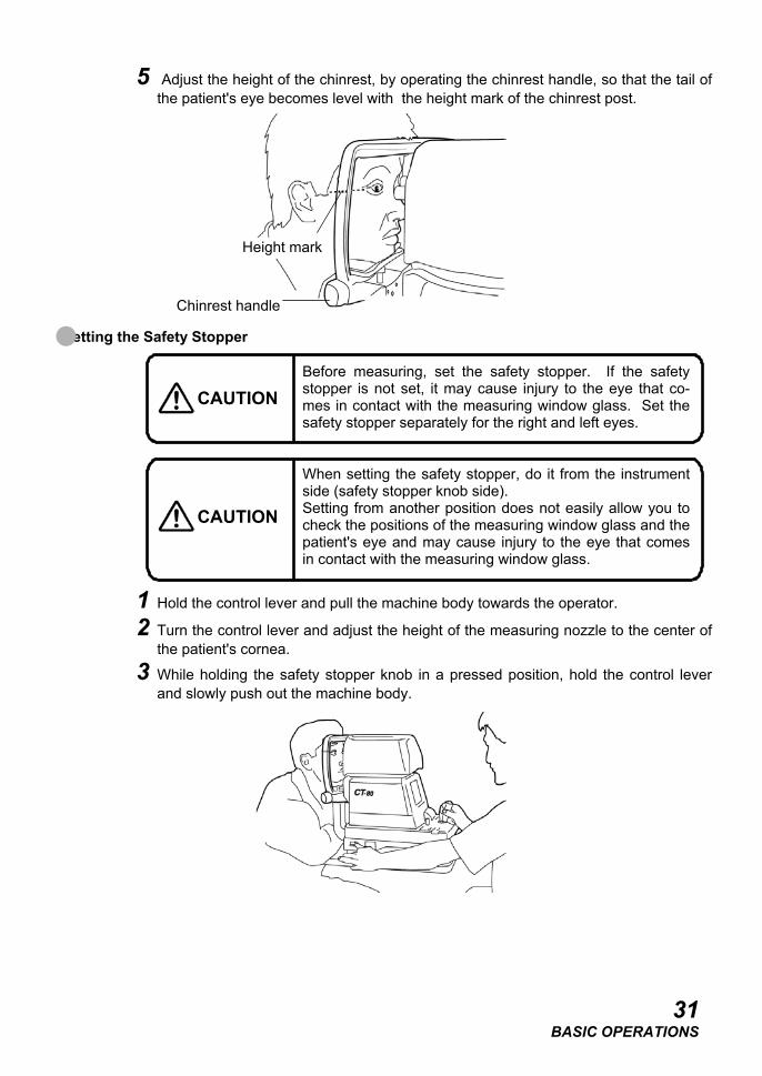
5 Adjust the height of the chinrest, by operating the chinrest handle, so that the tail ofthe patient's eye becomes level with the height mark of the chinrest post.
Setting the Safety Stopper
1 Hold the control lever and pull the machine body towards the operator.
2 Turn the control lever and adjust the height of the measuring nozzle to the center ofthe patient's cornea.
3 While holding the safety stopper knob in a pressed position, hold the control leverand slowly push out the machine body.
31BASIC OPERATIONS
Height mark
Chinrest handle
Before measuring, set the safety stopper. If the safetystopper is not set, it may cause injury to the eye that co-mes in contact with the measuring window glass. Set thesafety stopper separately for the right and left eyes.
CAUTION
When setting the safety stopper, do it from the instrumentside (safety stopper knob side).Setting from another position does not easily allow you tocheck the positions of the measuring window glass and thepatient's eye and may cause injury to the eye that comesin contact with the measuring window glass.
CAUTION
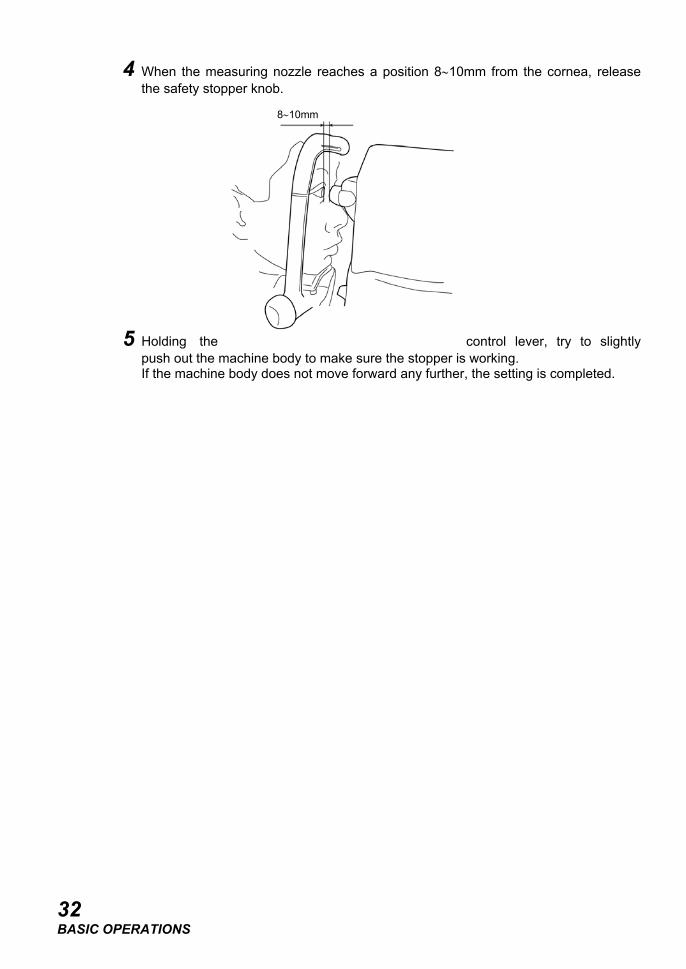
4 When the measuring nozzle reaches a position 8∼10mm from the cornea, releasethe safety stopper knob.
5 Holding the control lever, try to slightlypush out the machine body to make sure the stopper is working.If the machine body does not move forward any further, the setting is completed.
32BASIC OPERATIONS
8∼10mm
MEASUREMENT UNDER AUTO MODE
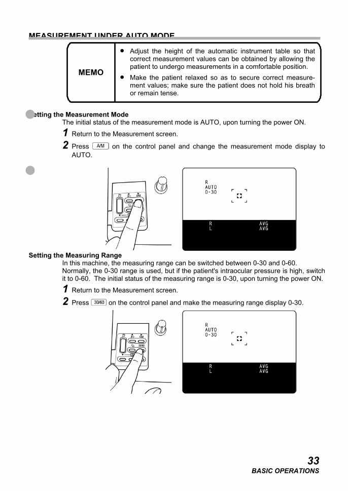
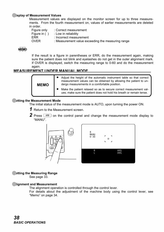
Setting the Measurement ModeThe initial status of the measurement mode is AUTO, upon turning the power ON.
1 Return to the Measurement screen.
2 Press on the control panel and change the measurement mode display toAUTO.
Setting the Measuring RangeIn this machine, the measuring range can be switched between 0-30 and 0-60.Normally, the 0-30 range is used, but if the patient's intraocular pressure is high, switchit to 0-60. The initial status of the measuring range is 0-30, upon turning the power ON.
1 Return to the Measurement screen.
2 Press on the control panel and make the measuring range display 0-30.
33BASIC OPERATIONS
• Adjust the height of the automatic instrument table so thatcorrect measurement values can be obtained by allowing thepatient to undergo measurements in a comfortable position.
• Make the patient relaxed so as to secure correct measure-ment values; make sure the patient does not hold his breathor remain tense.
MEMO
Alignment and Measurement
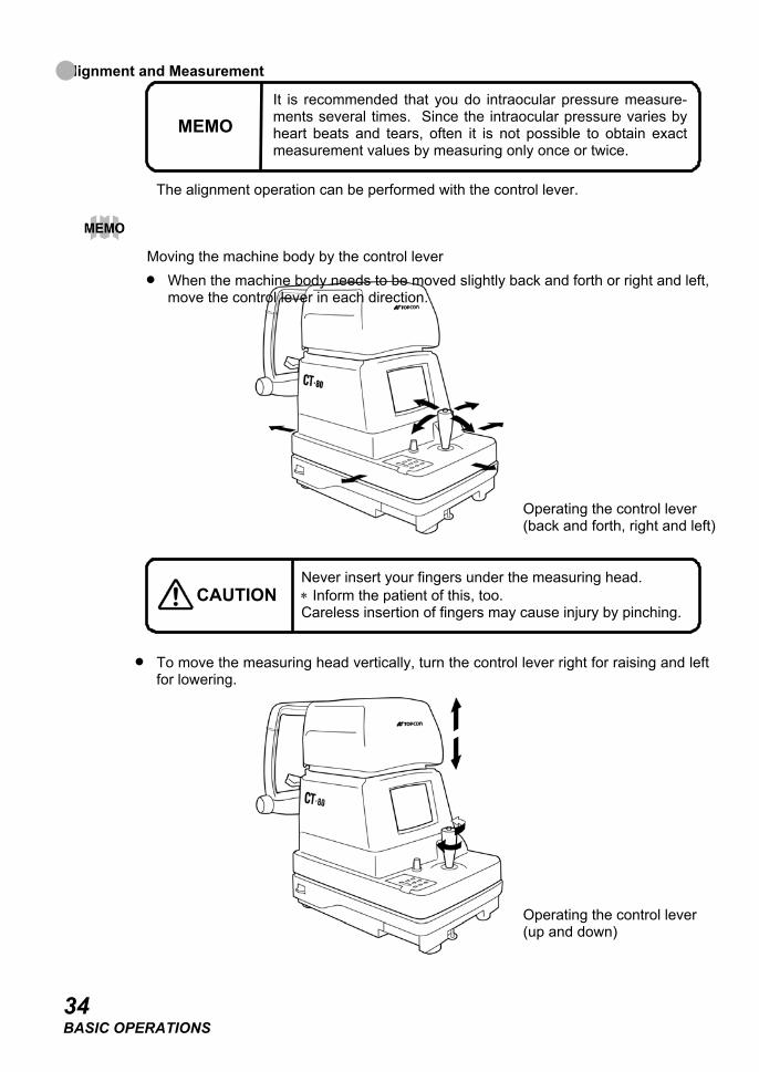
The alignment operation can be performed with the control lever.
• To move the measuring head vertically, turn the control lever right for raising and leftfor lowering.
34BASIC OPERATIONS
It is recommended that you do intraocular pressure measure-ments several times. Since the intraocular pressure varies byheart beats and tears, often it is not possible to obtain exactmeasurement values by measuring only once or twice.
MEMO
Moving the machine body by the control lever• When the machine body needs to be moved slightly back and forth or right and left,
move the control lever in each direction.
Operating the control lever(back and forth, right and left)
Operating the control lever(up and down)
Never insert your fingers under the measuring head.∗ Inform the patient of this, too.Careless insertion of fingers may cause injury by pinching.
CAUTION
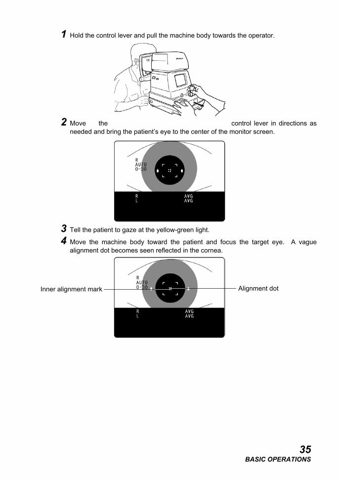
1 Hold the control lever and pull the machine body towards the operator.
2 Move the control lever in directions asneeded and bring the patient’s eye to the center of the monitor screen.
3 Tell the patient to gaze at the yellow-green light.
4 Move the machine body toward the patient and focus the target eye. A vaguealignment dot becomes seen reflected in the cornea.
35BASIC OPERATIONS
Inner alignment mark Alignment dot
5 Move the machine body in directions as needed in order to get the alignment dotwithin the inner alignment mark on the monitor screen.
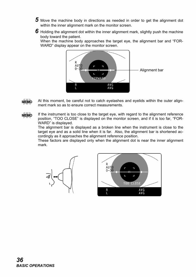
6 Holding the alignment dot within the inner alignment mark, slightly push the machinebody toward the patient.When the machine body approaches the target eye, the alignment bar and “FOR-WARD” display appear on the monitor screen.
36BASIC OPERATIONS
At this moment, be careful not to catch eyelashes and eyelids within the outer align-ment mark so as to ensure correct measurements.
If the instrument is too close to the target eye, with regard to the alignment referenceposition, “TOO CLOSE” is displayed on the monitor screen, and if it is too far, “FOR-WARD” is displayed.The alignment bar is displayed as a broken line when the instrument is close to thetarget eye and as a solid line when it is far. Also, the alignment bar is shortened ac-cordingly as it approaches the alignment reference position.These factors are displayed only when the alignment dot is near the inner alignmentmark.
Alignment bar
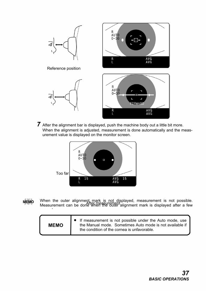
7 After the alignment bar is displayed, push the machine body out a little bit more.When the alignment is adjusted, measurement is done automatically and the meas-urement value is displayed on the monitor screen.
37BASIC OPERATIONS
When the outer alignment mark is not displayed, measurement is not possible.Measurement can be done when the outer alignment mark is displayed after a fewseconds
Reference position
Too far
After measurement
• If measurement is not possible under the Auto mode, usethe Manual mode. Sometimes Auto mode is not available ifthe condition of the cornea is unfavorable.
MEMO
Display of Measurement ValuesMeasurement values are displayed on the monitor screen for up to three measure-ments. From the fourth measurement on, values of earlier measurements are deletedin order.
Figure only : Correct measurementFigure in ( ) : Low in reliabilityERR : Incorrect measurementOVER : Measurement value exceeding the measuring range
MEASUREMENT UNDER MANUAL MODE
Setting the Measurement ModeThe initial status of the measurement mode is AUTO, upon turning the power ON.
1 Return to the Measurement screen.
2 Press on the control panel and change the measurement mode display to“MANU”.
Setting the Measuring RangeSee page 33.
Alignment and MeasurementThe alignment operation is controlled through the control lever.For details about the adjustment of the machine body using the control lever, see“Memo” on page 34.
38BASIC OPERATIONS
If the result is a figure in parentheses or ERR, do the measurement again, makingsure the patient does not blink and eyelashes do not get in the outer alignment mark.If OVER is displayed, switch the measuring range to 0-60 and do the measurementagain.
• Adjust the height of the automatic instrument table so that correctmeasurement values can be obtained by allowing the patient to un-dergo measurements in a comfortable position.
• Make the patient relaxed so as to secure correct measurement val-ues; make sure the patient does not hold his breath or remain tense.
MEMO
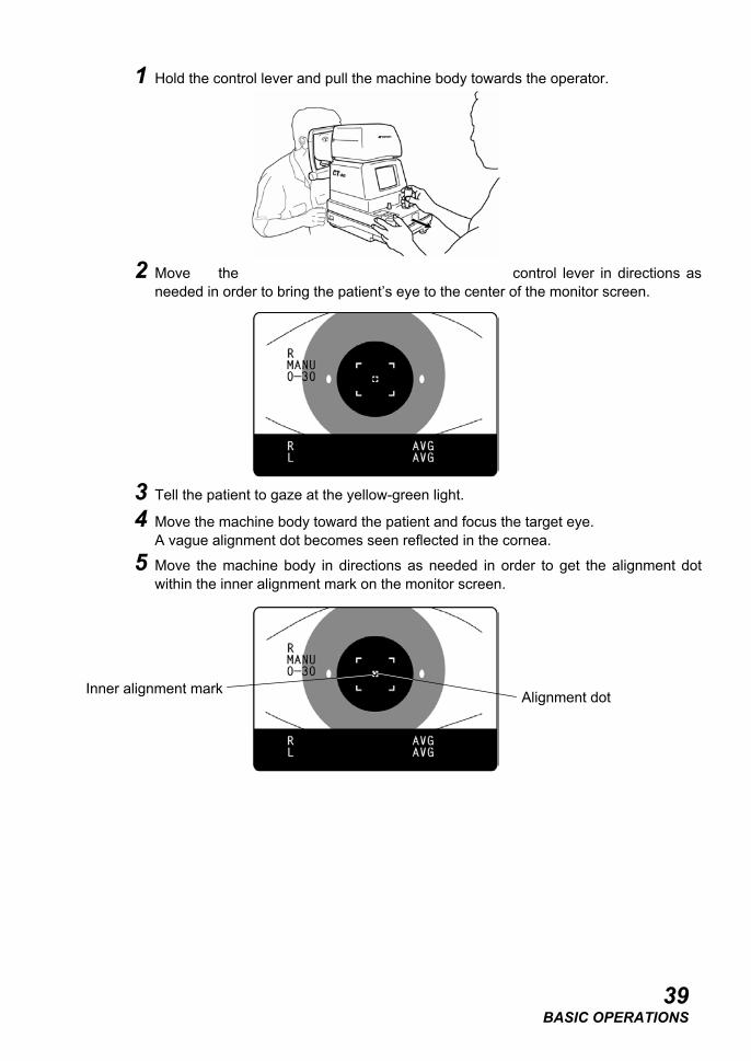
1 Hold the control lever and pull the machine body towards the operator.
2 Move the control lever in directions asneeded in order to bring the patient’s eye to the center of the monitor screen.
3 Tell the patient to gaze at the yellow-green light.
4 Move the machine body toward the patient and focus the target eye.A vague alignment dot becomes seen reflected in the cornea.
5 Move the machine body in directions as needed in order to get the alignment dotwithin the inner alignment mark on the monitor screen.
39BASIC OPERATIONS
Inner alignment mark Alignment dot
6 Holding the alignment dot within the inner alignment mark, slightly push the machinebody toward the patient.When the machine body approaches the target eye, the alignment bar and the“FORWARD” display appear on the monitor screen.
7 Move the machine body back and forth, with the alignment bar as a reference, whileholding the alignment dot within the inner alignment mark.When the alignment is adjusted, the shape of the inner alignment mark changes to a .
8 After the alignment is adjusted, press MEASUREMENT SWITCH .Air is ejected for measurement, and the measurement value is displayed.
40BASIC OPERATIONS
At this moment, be careful not to catch eyelashes and eyelids within the outer align-ment mark so as to ensure correct measurements.See descriptions about the alignment bar, “FORWARD” and “TOO CLOSE” on page36.
Alignment bar
Alignment is not adjusted Alignment is adjusted
MEMO• If the shape of the inner alignment mark does not change to a
even after correctly adjusting the alignment, check again to see ifthe alignment is adjusted correctly. Sometimes the shape of theinner alignment mark does not change to a if the condition ofthe cornea is unfavorable.
In Manual mode, measurement is done by pressing MEASUREMENT SWITCH even if thealignment is not adjusted correctly. To ensure high-precision measurements, makesure the alignment is adjusted correctly.

DELETING MEASUREMENT VALUES1 Press on the control panel.
All the measurement values of the right and left eyes are deleted and the instrumentsettings return to their status upon turning the power ON.
41BASIC OPERATIONS
INDIVIDUAL OPERATIONSHOW TO PRINT OUT MEASUREMENT VALUES
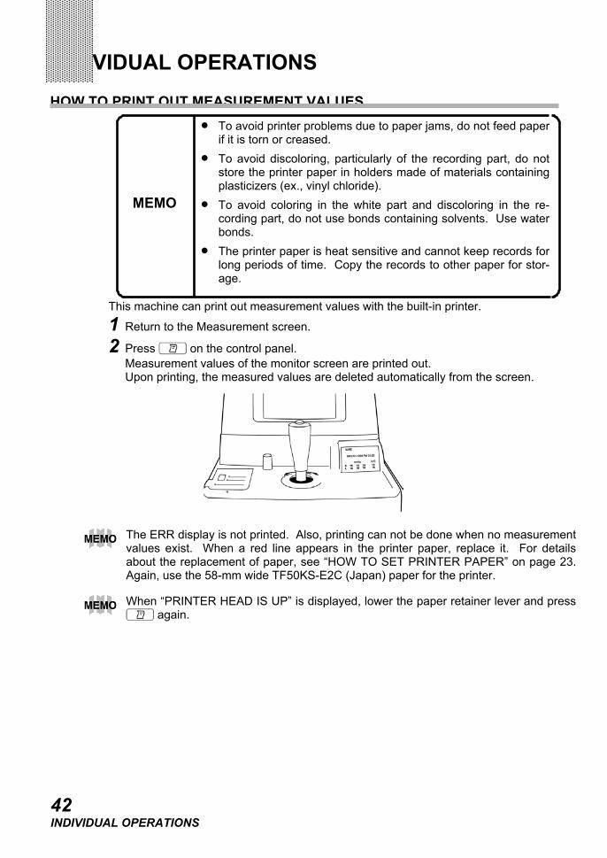
This machine can print out measurement values with the built-in printer.
1 Return to the Measurement screen.
2 Press on the control panel.Measurement values of the monitor screen are printed out.Upon printing, the measured values are deleted automatically from the screen.
42INDIVIDUAL OPERATIONS
The ERR display is not printed. Also, printing can not be done when no measurementvalues exist. When a red line appears in the printer paper, replace it. For detailsabout the replacement of paper, see “HOW TO SET PRINTER PAPER” on page 23.Again, use the 58-mm wide TF50KS-E2C (Japan) paper for the printer.
When “PRINTER HEAD IS UP” is displayed, lower the paper retainer lever and press again.
• To avoid printer problems due to paper jams, do not feed paperif it is torn or creased.
• To avoid discoloring, particularly of the recording part, do notstore the printer paper in holders made of materials containingplasticizers (ex., vinyl chloride).
• To avoid coloring in the white part and discoloring in the re-cording part, do not use bonds containing solvents. Use waterbonds.
• The printer paper is heat sensitive and cannot keep records forlong periods of time. Copy the records to other paper for stor-age.
MEMO

3 Hold the paper and pull it diagonally to cut.
HOW TO CORRECT MEASUREMENT VALUES
Though the machine is adjusted for displaying optimal measurement values, the valuescan be corrected within a -4 ∼ +3mmHg range.
1 Make sure the power is OFF.
2 Open the control panel lid.
3 Using a screwdriver, turn the “ ” of the select switch.
Settings: 0: Base setting For shipment, the switch is set here.1: +1mmHg Base setting + 1mmHg2: +2mmHg Base setting + 2mmHg3: +3mmHg Base setting + 3mmHgF: -1mmHg Base setting - 1mmHgE: -2mmHg Base setting - 2mmHgD: -3mmHg Base setting - 3mmHgC: -4mmHg Base setting - 4mmHg
4 Turn the POWER SWITCH ON.The measurement procedure is exactly the same as with the correction.
43INDIVIDUAL OPERATIONS
• To avoid paper jams, cut the paper carefully and evenly.MEMO
Never set the select switch for more than eight points to avoidmalfunctions.MEMO
Select switch
INPUT/OUTPUT VIA RS-232C
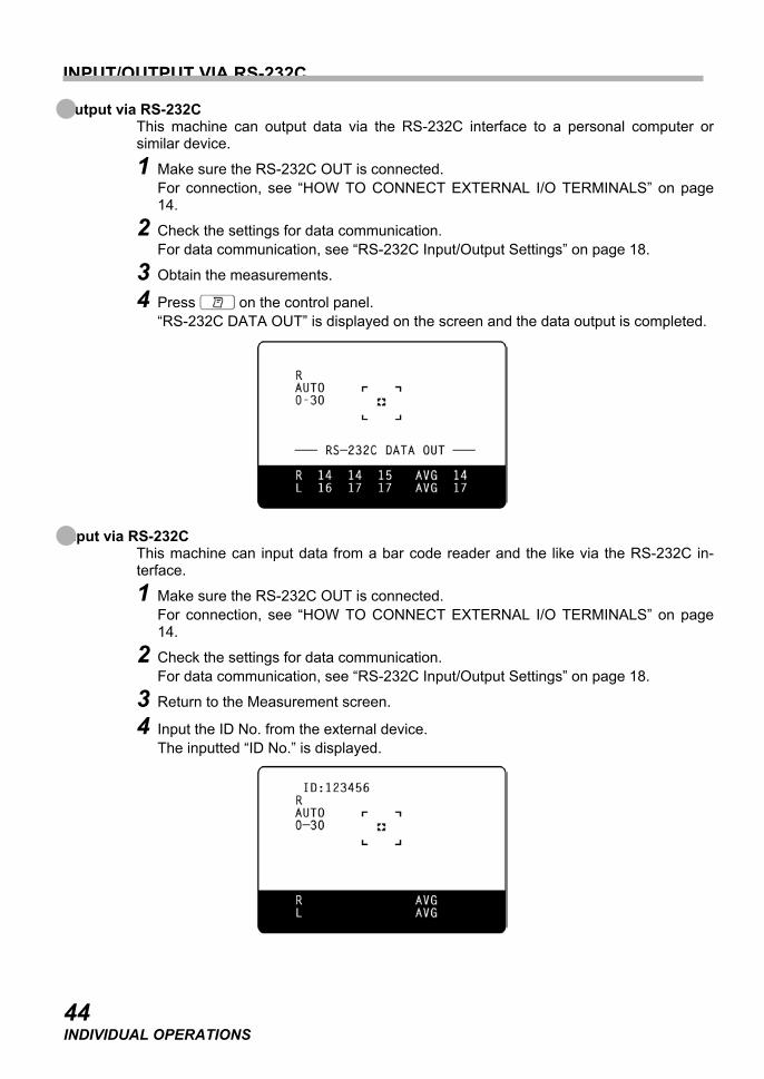
Output via RS-232CThis machine can output data via the RS-232C interface to a personal computer orsimilar device.
1 Make sure the RS-232C OUT is connected.For connection, see “HOW TO CONNECT EXTERNAL I/O TERMINALS” on page14.
2 Check the settings for data communication.For data communication, see “RS-232C Input/Output Settings” on page 18.
3 Obtain the measurements.
4 Press on the control panel.“RS-232C DATA OUT” is displayed on the screen and the data output is completed.
Input via RS-232CThis machine can input data from a bar code reader and the like via the RS-232C in-terface.
1 Make sure the RS-232C OUT is connected.For connection, see “HOW TO CONNECT EXTERNAL I/O TERMINALS” on page14.
2 Check the settings for data communication.For data communication, see “RS-232C Input/Output Settings” on page 18.
3 Return to the Measurement screen.
4 Input the ID No. from the external device.The inputted “ID No.” is displayed.
44INDIVIDUAL OPERATIONS
BEFORE REQUESTING SERVICECHECKING OPERATIONS
Air CheckIf a problem is suspected, do an air check.If the result is “NG (+)” or “NG (-),” call your dealer.For instructions on how to perform an air check, see “Air Check” on page 29.
Checking Operations
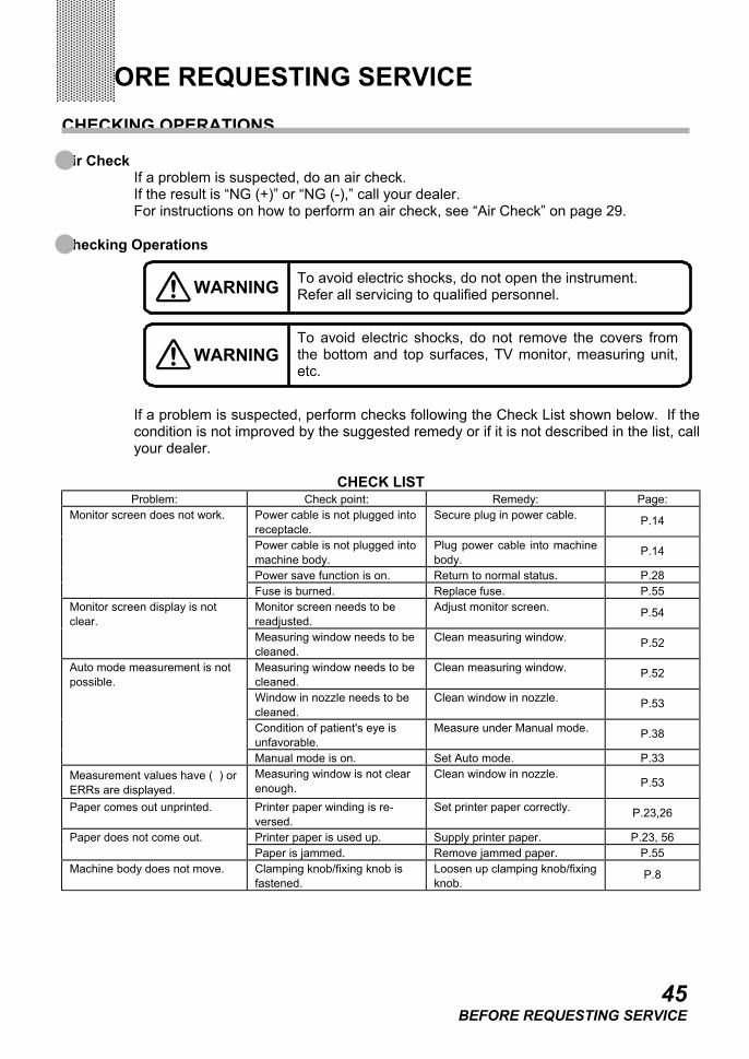
If a problem is suspected, perform checks following the Check List shown below. If thecondition is not improved by the suggested remedy or if it is not described in the list, callyour dealer.
CHECK LISTProblem: Check point: Remedy: Page:
Monitor screen does not work. Power cable is not plugged intoreceptacle.
Secure plug in power cable. P.14
Power cable is not plugged intomachine body.
Plug power cable into machinebody.
P.14
Power save function is on. Return to normal status. P.28Fuse is burned. Replace fuse. P.55
Monitor screen display is notclear.
Monitor screen needs to bereadjusted.
Adjust monitor screen. P.54
Measuring window needs to becleaned.
Clean measuring window. P.52
Auto mode measurement is notpossible.
Measuring window needs to becleaned.
Clean measuring window. P.52
Window in nozzle needs to becleaned.
Clean window in nozzle. P.53
Condition of patient's eye isunfavorable.
Measure under Manual mode. P.38
Manual mode is on. Set Auto mode. P.33Measurement values have ( ) orERRs are displayed.
Measuring window is not clearenough.
Clean window in nozzle.P.53
Paper comes out unprinted. Printer paper winding is re-versed.
Set printer paper correctly. P.23,26
Paper does not come out. Printer paper is used up. Supply printer paper. P.23, 56Paper is jammed. Remove jammed paper. P.55
Machine body does not move. Clamping knob/fixing knob isfastened.
Loosen up clamping knob/fixingknob.
P.8
45BEFORE REQUESTING SERVICE
To avoid electric shocks, do not open the instrument.Refer all servicing to qualified personnel.WARNING
To avoid electric shocks, do not remove the covers fromthe bottom and top surfaces, TV monitor, measuring unit,etc.
WARNING
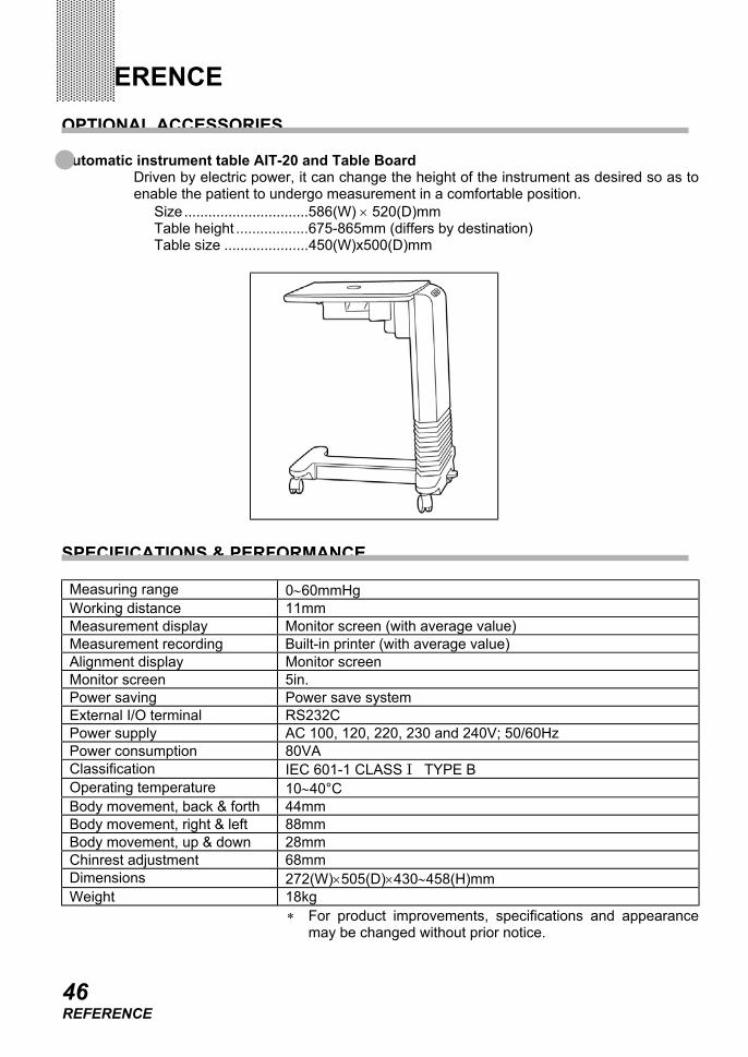
REFERENCEOPTIONAL ACCESSORIES
Automatic instrument table AIT-20 and Table BoardDriven by electric power, it can change the height of the instrument as desired so as toenable the patient to undergo measurement in a comfortable position.
Size...............................586(W) × 520(D)mmTable height ..................675-865mm (differs by destination)Table size .....................450(W)x500(D)mm
SPECIFICATIONS & PERFORMANCE
Measuring range 0∼60mmHgWorking distance 11mmMeasurement display Monitor screen (with average value)Measurement recording Built-in printer (with average value)Alignment display Monitor screenMonitor screen 5in.Power saving Power save systemExternal I/O terminal RS232CPower supply AC 100, 120, 220, 230 and 240V; 50/60HzPower consumption 80VAClassification IEC 601-1 CLASS I TYPE BOperating temperature 10∼40°CBody movement, back & forth 44mmBody movement, right & left 88mmBody movement, up & down 28mmChinrest adjustment 68mmDimensions 272(W)×505(D)×430∼458(H)mmWeight 18kg
∗ For product improvements, specifications and appearancemay be changed without prior notice.
46REFERENCE
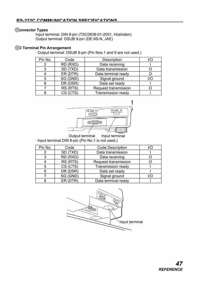
RS-232C COMMUNICATION SPECIFICATIONS
Connector TypesInput terminal: DIN 8-pin (TSC0838-01-2051, Hoshiden)Output terminal: DSUB 9-pin (DE-9S-N, JAE)
I/O Terminal Pin Arrangement⋅ Output terminal: DSUB 9-pin (Pin Nos.1 and 9 are not used.)
Pin No. Code Description I/O2 RD (RXD) Data receiving I3 SD (TXD) Data transmission O4 ER (DTR) Data terminal ready O5 SG (GND) Signal ground I/O6 DR (DSR) Data set ready I7 RS (RTS) Request transmission O8 CS (CTS) Transmission ready I
⋅ Input terminal DIN 8-pin (Pin No.1 is not used.)
Pin No. Code Code Description I/O2 SD (TXD) Data transmission I3 RD (RXD) Data receiving O4 RS (RTS) Request transmission O5 CS (CTS) Transmission ready I6 DR (DSR) Data set ready I7 SG (GND) Signal ground I/O8 ER (DTR) Data terminal ready I
47REFERENCE
Input terminalOutput terminal
Input terminal
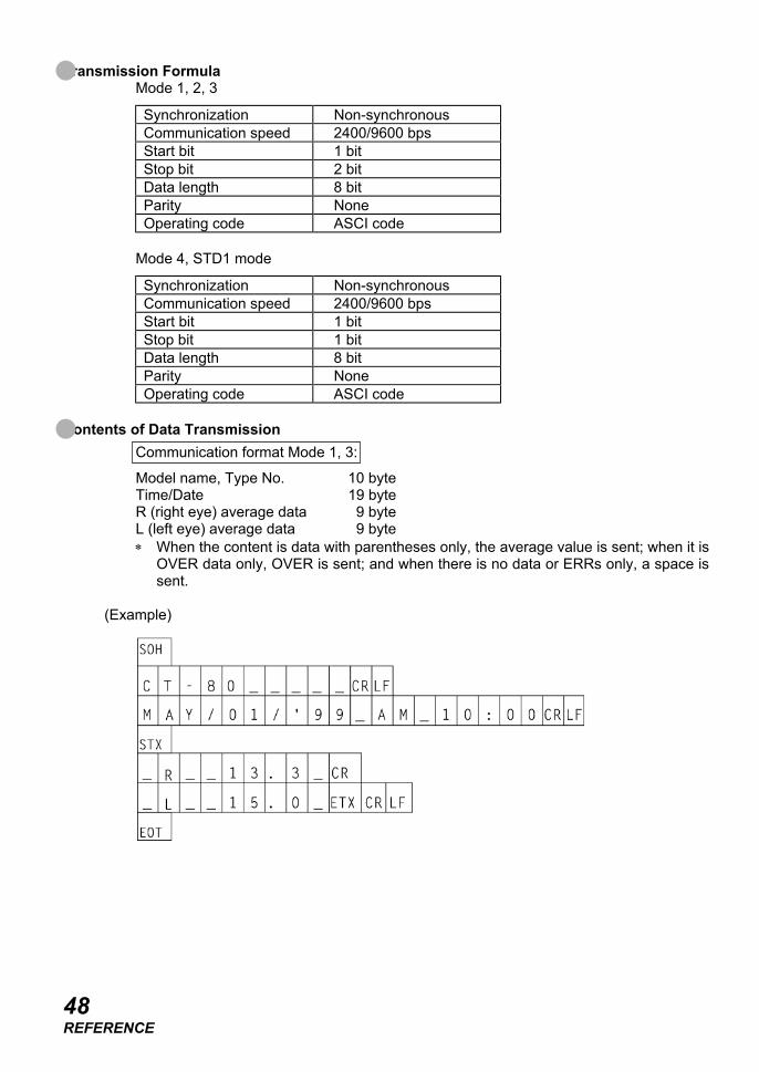
Transmission FormulaMode 1, 2, 3
Synchronization Non-synchronousCommunication speed 2400/9600 bpsStart bit 1 bitStop bit 2 bitData length 8 bitParity NoneOperating code ASCI code
Mode 4, STD1 mode
Synchronization Non-synchronousCommunication speed 2400/9600 bpsStart bit 1 bitStop bit 1 bitData length 8 bitParity NoneOperating code ASCI code
Contents of Data TransmissionCommunication format Mode 1, 3:
Model name, Type No. 10 byteTime/Date 19 byteR (right eye) average data 9 byteL (left eye) average data 9 byte∗ When the content is data with parentheses only, the average value is sent; when it is
OVER data only, OVER is sent; and when there is no data or ERRs only, a space issent.
(Example)
48REFERENCE
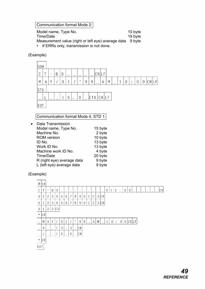
Communication format Mode 2:
Model name, Type No. 10 byteTime/Date 19 byteMeasurement value (right or left eye) average data 9 byte∗ If ERRs only, transmission is not done.
(Example)
Communication format Mode 4, STD 1:
• Data TransmissionModel name, Type No. 15 byteMachine No. 2 byteROM version 10 byteID No. 13 byteWork ID No. 13 byteMachine work ID No. 4 byteTime/Date 20 byteR (right eye) average data 9 byteL (left eye) average data 9 byte
(Example)
49REFERENCE
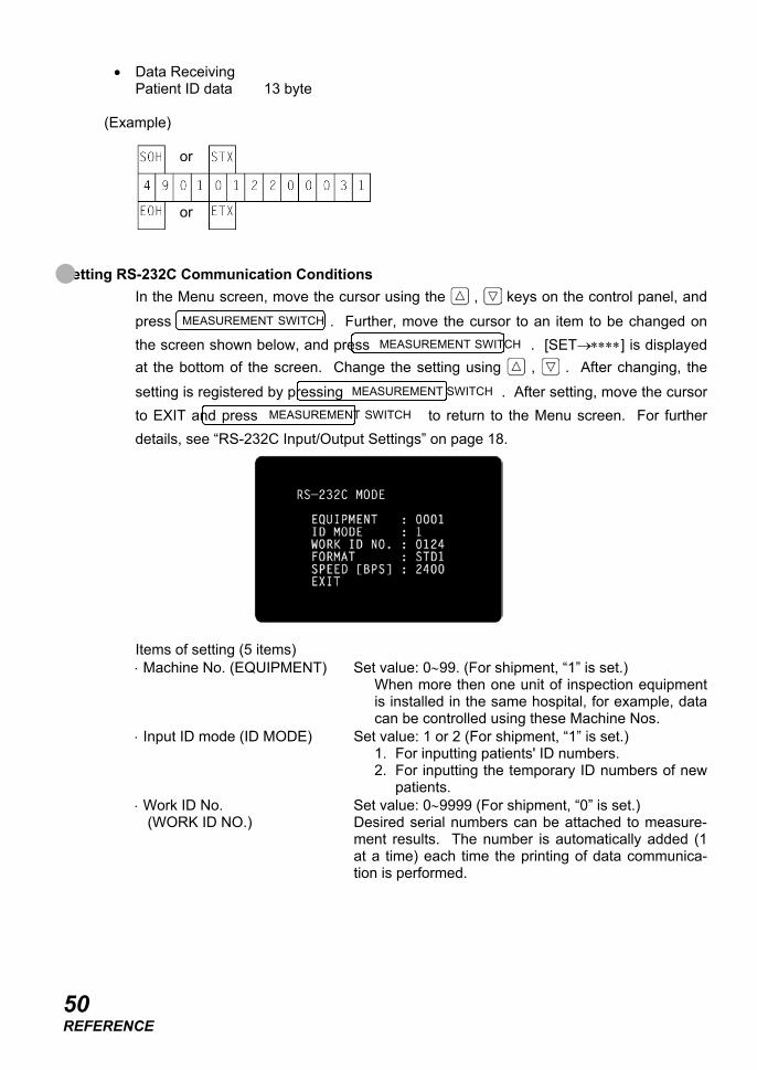
• Data ReceivingPatient ID data 13 byte
(Example)
Setting RS-232C Communication ConditionsIn the Menu screen, move the cursor using the , keys on the control panel, andpress MEASUREMENT SWITCH . Further, move the cursor to an item to be changed onthe screen shown below, and press MEASUREMENT SWITCH . [SET→∗∗∗∗] is displayedat the bottom of the screen. Change the setting using , . After changing, thesetting is registered by pressing MEASUREMENT SWITCH . After setting, move the cursorto EXIT and press MEASUREMENT SWITCH to return to the Menu screen. For furtherdetails, see “RS-232C Input/Output Settings” on page 18.
Items of setting (5 items)⋅ Machine No. (EQUIPMENT) Set value: 0∼99. (For shipment, “1” is set.)
When more then one unit of inspection equipmentis installed in the same hospital, for example, datacan be controlled using these Machine Nos.
⋅ Input ID mode (ID MODE) Set value: 1 or 2 (For shipment, “1” is set.)1. For inputting patients' ID numbers.2. For inputting the temporary ID numbers of new
patients.⋅ Work ID No. Set value: 0∼9999 (For shipment, “0” is set.) (WORK ID NO.) Desired serial numbers can be attached to measure-
ment results. The number is automatically added (1at a time) each time the printing of data communica-tion is performed.
50REFERENCE
or
or

⋅ Communication format Format: OFF, MODE 1, MODE 2, MODE 3, MODE 4, (FORMAT) STD 1 (For shipment, “OFF” is set.)
MODE 1:When is pressed, communication is doneafter printing.
MODE 2:Data communication is done every measure-ment.
MODE 3:When is pressed, communication is donewithout printing.
MODE 4:When is pressed, communication is donewithout printing.
STD 1: When is pressed, communication is doneafter printing.
⋅ Communication speed (SPEED) Baud rate: 2400, 9600 (bps) (For shipment,2400bps is set.)
51REFERENCE
The Topcon CT-80 complies with the CE marking.Before connecting a personal computer to the TOPCONproduct, make sure that such external equipment is incompliance with the CE marking.
Under the RTS-CTS control, if no CS (CTS) signal is returned from the receiver side,transmission can be canceled by pressing . Also, if no DR (DSR) signal is re-turned, it is recognized as a communication failure and FAIL is displayed on themonitor screen.
When Mode 1, 2 or 3 is set, data is transmitted automatically without confirmationfrom the receiver side. When STD 1 is set, communication is controlled by RTS-CTS.
MAINTENANCE AND CHECKINGACCURACY MAINTENANCE
Cleaning the Measuring Window Glass• To secure auto alignment and correct measurement values, clean the measuring
window glass after each day’s work.• Clean the glass when “CLEAN THE MEASURING WINDOW GLASS” is displayed
on the monitor screen.
1 Prepare the ethanol.
2 Using a blower, remove dust and dirt from the glass surface.
3 Moisten the applicator with ethanol.
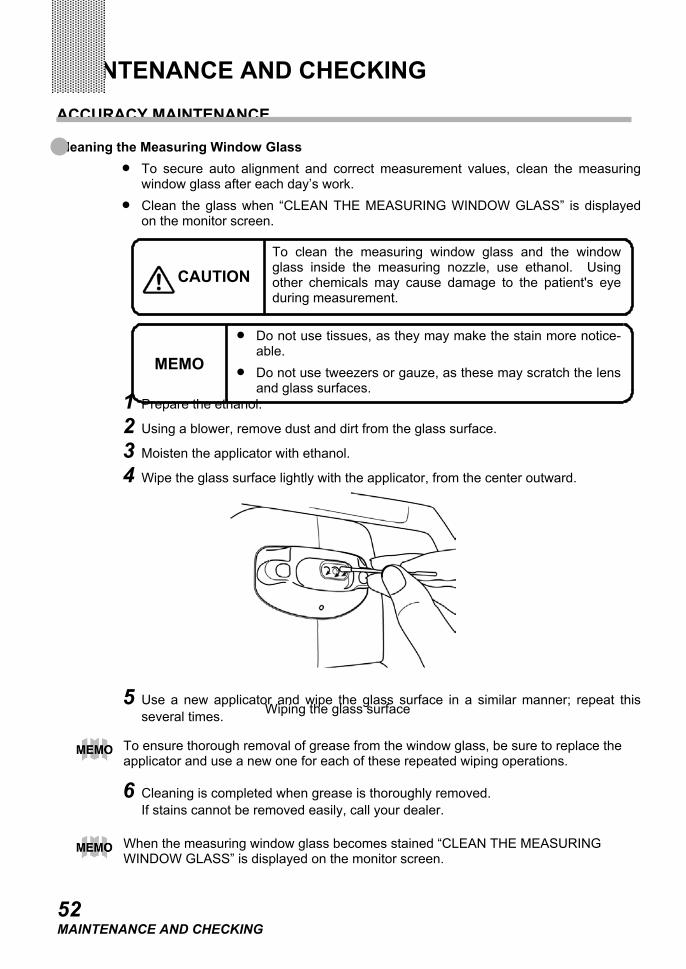
4 Wipe the glass surface lightly with the applicator, from the center outward.
5 Use a new applicator and wipe the glass surface in a similar manner; repeat thisseveral times.
6 Cleaning is completed when grease is thoroughly removed.If stains cannot be removed easily, call your dealer.
52MAINTENANCE AND CHECKING
To clean the measuring window glass and the windowglass inside the measuring nozzle, use ethanol. Usingother chemicals may cause damage to the patient's eyeduring measurement.
CAUTION
• Do not use tissues, as they may make the stain more notice-able.
• Do not use tweezers or gauze, as these may scratch the lensand glass surfaces.
MEMO
To ensure thorough removal of grease from the window glass, be sure to replace theapplicator and use a new one for each of these repeated wiping operations.
When the measuring window glass becomes stained “CLEAN THE MEASURINGWINDOW GLASS” is displayed on the monitor screen.
Wiping the glass surface

Cleaning the Window Glass inside the Nozzle• When the window glass inside the nozzle becomes stained, it makes the fixation tar-
get unclear, causing errors in auto alignment and measurement values. If the fixa-tion target is unclear or measurement values with parentheses are frequent, cleanthe window glass inside the nozzle.
• Clean the glass when “CLEAN THE CHAMBER GLASS” is displayed on the monitorscreen.
1 Prepare the ethanol.
2 Moisten the applicator with ethanol.
3 Insert the applicator into the nozzle, lightly touch the glass surface, and turn the ap-plicator a few times.
4 Use a new applicator and wipe the glass surface in a similar manner; repeat this afew times .
5 Cleaning is completed when the grease is thoroughly removed.If stains cannot be removed easily, call your dealer. Press for a air check toconfirm normal operation.
53MAINTENANCE AND CHECKING
To clean the measuring window glass and the windowglass inside the measuring nozzle, use ethanol. Usingother chemicals may cause damage to the patient's eyeduring measurement.
CAUTION
• Do not apply unreasonable force to the measuring nozzlewhile cleaning.
• To avoid problems, do not leave the cotton fibers inside.• Be sure to use only the attached applicator.
MEMO
The used applicator contains grease and it only scatters grease if used again; the lighttransmittance is not improved at all. Be sure to replace the applicator and use a newone for each of these repeated cleaning operations.
When the window glass inside the nozzle becomes stained, it makes the fixation tar-get unclear and “CLEAN THE CHAMBER GLASS” is displayed on the monitor screen.
Applicator (attached)
Daily Maintenance• This machine must be kept free of dust; apply the measuring window cap and dust
cover when not in use.• When not in use, turn the POWER SWITCH OFF.
Ordering Consumable Supplies• When placing an order for consumable supplies, tell your dealer the product name,
part code and quantity.
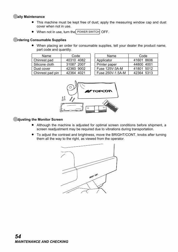
Name CodeChinrest pad 40310 4082Silicone cloth 31087 2007Dust cover 42360 9002Chinrest pad pin 42364 4021
Name CodeApplicator 41601 8606Printer paper 44800 4001Fuse 125V-3A-M 41801 5012Fuse 250V-1.5A-M 42364 5313
Adjusting the Monitor Screen• Although the machine is adjusted for optimal screen conditions before shipment, a
screen readjustment may be required due to vibrations during transportation.• To adjust the contrast and brightness, move the BRIGHT/CONT. knobs after turning
them all the way to the right, as viewed from the operator.
54MAINTENANCE AND CHECKING
Paper Jam in Printer
• Remove the printer cover, release the paper retainer lever and remove the jammedpaper.
Replacing the Fuse
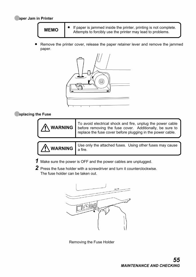
1 Make sure the power is OFF and the power cables are unplugged.
2 Press the fuse holder with a screwdriver and turn it counterclockwise.The fuse holder can be taken out.
55MAINTENANCE AND CHECKING
• If paper is jammed inside the printer, printing is not complete.Attempts to forcibly use the printer may lead to problems.MEMO
To avoid electrical shock and fire, unplug the power cablebefore removing the fuse cover. Additionally, be sure toreplace the fuse cover before plugging in the power cable.
WARNING
Use only the attached fuses. Using other fuses may causea fire.WARNING
Removing the Fuse Holder
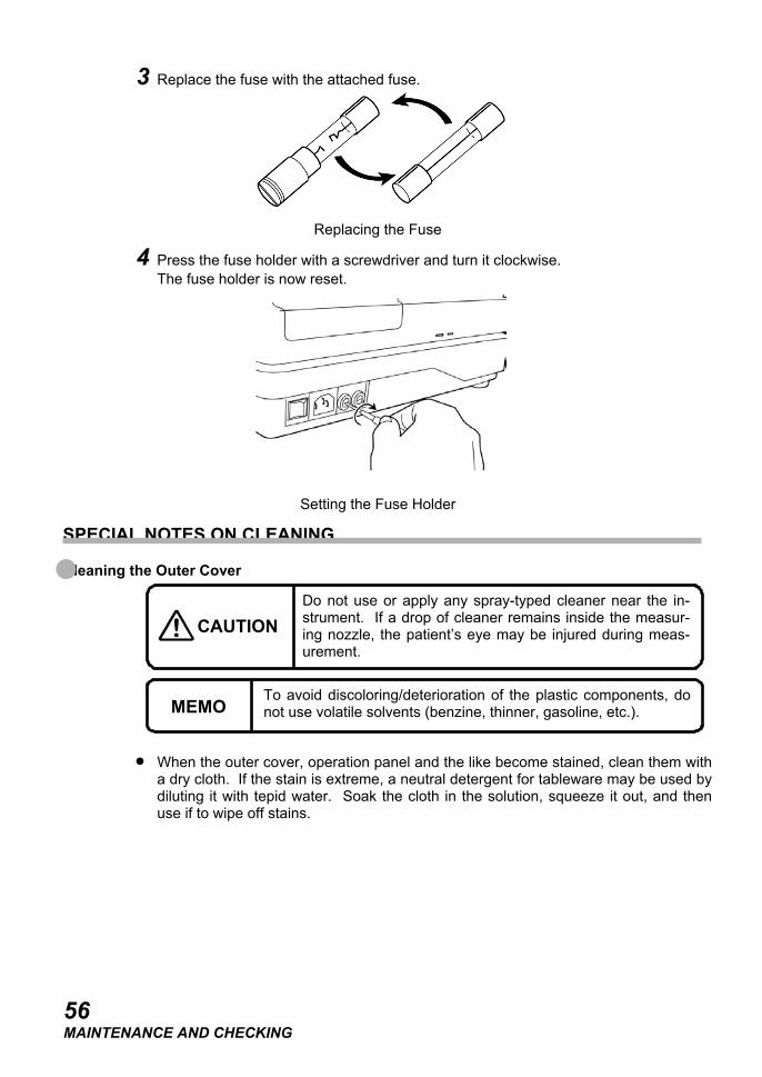
3 Replace the fuse with the attached fuse.
4 Press the fuse holder with a screwdriver and turn it clockwise.The fuse holder is now reset.
SPECIAL NOTES ON CLEANING
Cleaning the Outer Cover
• When the outer cover, operation panel and the like become stained, clean them witha dry cloth. If the stain is extreme, a neutral detergent for tableware may be used bydiluting it with tepid water. Soak the cloth in the solution, squeeze it out, and thenuse if to wipe off stains.
56MAINTENANCE AND CHECKING
Do not use or apply any spray-typed cleaner near the in-strument. If a drop of cleaner remains inside the measur-ing nozzle, the patient’s eye may be injured during meas-urement.
CAUTION
To avoid discoloring/deterioration of the plastic components, donot use volatile solvents (benzine, thinner, gasoline, etc.).MEMO
Replacing the Fuse
Setting the Fuse Holder
When calling please give us the following infor-mation about your unit:
⋅ Machine type: CT-80⋅ Manufacturing No. (Shown on the rating plate on
the right side of the base.)⋅ Period of Usage (Please give us the date of pur-
chase).⋅ Description of Problem (as detailed as possible).
COMPUTERIZED TONOMETER (CT-80)
INSTRUCTION MANUALVersion of 1999 (9906-100LW0)Date of issue: 1st, June, 1999
Published by
75-1 Hasunuma-cho, Itabashi-ku, Tokyo, 174-8580 Japan.
© 1999 TOPCON CORPORATIONALL RIGHTS RESERVED
COMPUTERIZED TONOMETER
CT-80
TOPCON AMERICA CORPORATIONCORPORATE OFFICE:37 West Century Road, Paramus, New Jersey 07652, U.S.A. Phone: 201-261-9450 Fax: 201-387-2710 www.topcon.com
TOPCON CANADA INC.110 Provencher Avenue, Boisbriand, QC J7G 1N1 CANADA Phone: 514-430-7771 Fax: 514-430-6457
TOPCON OMNI SYSTEMS, INC.Valley Forge Business Center, 2430 Blvd. of the Generals, Norristown, PA 19403, U.S.A Phone: 610-630-9200 Fax: 610-630-6428
TOPCON EUROPE B.V.(European Representative)ESSE Baan 11, 2908 LJ Capelle a/d IJssel, THE NETHERLANDS. Phone: 010-4585077 Fax: 010-4585045 www.topconeurope.com
TOPCON DEUTSCHLAND G.m.b.H.Halskestrasse 7 47877 Willich, GERMANY. Phone: 02154-9290 Fax: 02154-929111
TOPCON ESPAÑA S.A.HEAD OFFICE:Frederic Mompou 5, 08960, Sant Just Desvern Barcelona, SPAIN Phone: 93-4734057 Fax: 93-4191532MADRID OFFICE:Avenida Ciudad de Barcelona 81, 1 Planta 28007, Madrid, SPAIN Phone: 91-5524160 Fax: 91-5524161
TOPCON S.A.R.L.HEAD OFFICE:104/106, Rue Rivay, 92300, Levallois-Perret, FRANCE. Phone: 014106-9494 Fax: 014739-0251LYON OFFICE:138, Avenue du 8 Mai 1945, 69100 Villeurbanne, FRANCE Phone: 0478688237 Fax: 0478681902TOPCON SCANDINAVIA A. B.Industrivägen 4 P.O.Box 2140 43302 Sävedalen SWEDEN Phone: 031-261250 Fax: 031-268607TOPCON (GREAT BRITAIN) LTD.Topcon House,Kennet Side,Bone Lane,Newbury,Berkshire RG14 5PX United Kingdom Phone:01635-551120 Fax:01635-551170
TOPCON SINGAPORE PTE.LTD.Alexandra Distripark Block 4, #05-15, Pasir Panjang Road, Singapore 118491 Phone: 2780222 Fax: 2733540 web.singnet.com.sg/˜topconts
TOPCON INSTRUMENTS (MALAYSIA) SDN. BHD.Lot 226 Jalan Negara 2, Pusat Bandar Taman Melawati, Taman Melawati 53100 Kuala Lumpur, MALAYSIA. Phone: 03-4079801 Fax: 03-4079796TOPCON INSTRUMENTS (THAILAND) CO., LTD.77/162 Sinn Sathorn Tower, 37th Fl.,Krungdhonburi Rd.,Klongtonsai, Klongsarn, Bangkok 10600 Phone: 662-440-1152~7 Fax: 662-440-1158
TOPCON AUSTRALIA PTY.LTD.408 Victoria Road, Gladesville, NSW 2111, AUSTRALIA Phone: 02-9817-4666 Fax: 02-9817-4654 www.topcon.com.au
TOPCON KOREA CORPORATIONHyobong Bldg., 1-1306, Seocho-Dong, Seocho-Gu, Seoul, KOREA. Phone: 02-3482-9231 Fax: 02-3481-1928 www.topcon.co.kr
TOPCON OPTICAL (H.K.) LTD.2/F Meeco Industrial Bldg., No.53-55 Au Pui Wan Street, Fo Tan Road, Shatin, N.T., Hong KongPhone: 2690-1328 Fax: 2690-2221 E-mail: [email protected]
TOPCON CORPORATION BEIJING OFFICERoom No. 962 Poly Plaza Building, 14 Dongzhimen Nandajie Dongcheng District, Beijing, 100027, CHINA Phone: 10-6501-4191~2 Fax: 10-6501-4190
TOPCON CORPORATION BEIRUT OFFICEP.O.BOX 70-1002 Antelias, BEIRUT-LEBANON Phone: 961-4-523525/523526 Fax: 961-4-521119
TOPCON CORPORATION DUBAI OFFICEOffice No.102 KHALAF RASHD AL NAYLI BLDG., Deira, Dubai, UAE Phone: 971-4-696511 Fax: 971-4-695272
TOPCON CORPORATION75-1 Hasunuma-cho,Itabashi-ku,Tokyo,174-8580 Japan.Phone:3-3558-2520 Fax:3-3960-4214