Embed Size (px)
DESCRIPTION
tutorial
Citation preview

TopSolid’Wood 2008
Missler Software 1
Getting started with TopSolid’Wood 2008

TopSolid’Wood 2008
2 Missler Software
© 2008, Missler Software. 7, Rue du Bois Sauvage F-91055 Evry, FRANCE Web: http://topsolid.com E-mail: [email protected] All rights reserved. This information can be changed at any given time without notice. Not the entire contents of this document or part of it can be reproduced or transmitted, no matter the way, electronic or mechanical media used to do it or destination, without the formal and written authorization of Missler Software. TopSolid ® is a trade mark of Missler Software. TopSolid ® is a registered product name of Missler Software. The information and software program described in this document are subject to be modified without previous notice and do no have to be considered as any kind of commitment from Missler Software. The software program described by this document is provided under license and can only be used or duplicated under the terms of the license.

TopSolid’Wood 2008
Missler Software 3
Contents Presentation of TopSolid’Wood .................................................................................... 7
General issues ............................................................................................................................. 8 User Interface Overview ................................................................................................. 9
General environnement.............................................................................................................. 10 Mouse functions ......................................................................................................................... 11 Functionality ............................................................................................................................... 13 The buttons ................................................................................................................................ 13 Keyboard actions ....................................................................................................................... 14 Entering in coordinates .............................................................................................................. 15 The compass .............................................................................................................................. 15 Status bar ................................................................................................................................... 16 Added bars ................................................................................................................................. 16 Layers management .................................................................................................................. 17 Main functions ............................................................................................................................ 17
2D Functions ................................................................................................................. 21 Sketch line .................................................................................................................................. 22 Line ............................................................................................................................................. 22 Rectangle ................................................................................................................................... 23 Circle .......................................................................................................................................... 23 Axes ........................................................................................................................................... 24 Offset curve ................................................................................................................................ 25 Thickened curve ......................................................................................................................... 25 Standard curve ........................................................................................................................... 26 Regular polygon ......................................................................................................................... 26 Arc bend ..................................................................................................................................... 27 Middle curve ............................................................................................................................... 27 Ellipse ......................................................................................................................................... 27 Spiral .......................................................................................................................................... 28 Splines ........................................................................................................................................ 28 C-Spline ...................................................................................................................................... 29 Contour ....................................................................................................................................... 29
The contour function .................................................................................................... 31 The contour function .................................................................................................................. 32 Constraints ................................................................................................................................. 33 Link and join ............................................................................................................................... 34 Protractor.................................................................................................................................... 35 Trace modes .............................................................................................................................. 36 Dimension .................................................................................................................................. 37 Modifying dimensions ................................................................................................................. 38 Dependencies between dimensions .......................................................................................... 38 Parameters ................................................................................................................................. 39 Types of contours ....................................................................................................................... 40 Point by point contour ................................................................................................................ 40 Traced contours ......................................................................................................................... 41 Mixed contours (combination of the elements above) ............................................................... 41 Points ......................................................................................................................................... 42 Example of use of points. ........................................................................................................... 43
Simple shapes .............................................................................................................. 45 Extruded ..................................................................................................................................... 46 Revolved .................................................................................................................................... 47 Pipe ............................................................................................................................................ 47

TopSolid’Wood 2008
4 Missler Software
Block ........................................................................................................................................... 48 Cylinder ...................................................................................................................................... 49 Cone ........................................................................................................................................... 49 Sphere ........................................................................................................................................ 49
Complex shapes ........................................................................................................... 51 Ruled .......................................................................................................................................... 52 Swept ......................................................................................................................................... 52 Multi-criteria selection. ............................................................................................................... 53
Control elements, display and layers ......................................................................... 55 Control elements ........................................................................................................................ 56 Local mode ................................................................................................................................. 56 Global mode ............................................................................................................................... 56 Display ........................................................................................................................................ 57 Layers ......................................................................................................................................... 58 Quick layers bar ......................................................................................................................... 59 Layer editor ................................................................................................................................ 59
Operations ..................................................................................................................... 61 Drilling ........................................................................................................................................ 62 Pocket ........................................................................................................................................ 63 Boss ........................................................................................................................................... 63 Trim ............................................................................................................................................ 64 Subtract ...................................................................................................................................... 64 Unite ........................................................................................................................................... 64 Intersect ...................................................................................................................................... 65 Fillet ............................................................................................................................................ 65 Chamfer ...................................................................................................................................... 65 Draft ............................................................................................................................................ 65 Shell ........................................................................................................................................... 66 Threading ................................................................................................................................... 66 Groove ........................................................................................................................................ 66 Propagation of operations .......................................................................................................... 67 Coordinate Systems ................................................................................................................... 69 Examples of the use of coordinate systems .............................................................................. 70
Memo : Duplicate – Repeat .......................................................................................... 73 Duplicate .................................................................................................................................... 74 Subsequent operations .............................................................................................................. 74 Existing operations ..................................................................................................................... 75 Use in the BOM .......................................................................................................................... 76 Repeat ........................................................................................................................................ 77 Total distance : ........................................................................................................................... 78 Distance per instance................................................................................................................. 78 Using the construction tree ........................................................................................................ 78 Using the wrench ....................................................................................................................... 79 Excluding instances of a repetition ............................................................................................ 80 Modifying the template ............................................................................................................... 81 Operations on repetitions ........................................................................................................... 81 Use in the BOM .......................................................................................................................... 82
Memo : Different assembly methods .......................................................................... 83 Introduction ................................................................................................................................ 84 Designing a project .................................................................................................................... 85
Workshop : Creation of a circular rail......................................................................... 87 Circular rail - Rail's design ......................................................................................................... 88

TopSolid’Wood 2008
Missler Software 5
Creation of the rails .................................................................................................................... 90 Blind dovetail .............................................................................................................................. 93
Workshop : Creation of an easel ................................................................................. 95 Create the geometry of the easel ............................................................................................... 96 Model the easel .......................................................................................................................... 99 Tenon the cross-pieces ............................................................................................................ 100 Assembly by tenon-mortice ...................................................................................................... 103
Workshop : Creation of a trestle ............................................................................... 105 Create the geometry of the trestle ........................................................................................... 106 Model the trestle ....................................................................................................................... 111 Tenon the lower cross-piece .................................................................................................... 113 Assembly by tenon-mortice ...................................................................................................... 114
Workshop : Creation of a door .................................................................................. 117 Create the geometry for the door ............................................................................................. 118 Profiling the jambs and transoms ............................................................................................. 119 Counter molding of the transoms ............................................................................................. 120 Model the panel ........................................................................................................................ 121 Profiling the panel .................................................................................................................... 121
Workshop : Creation of a kitchen table .................................................................... 123 Create the table’s legs ............................................................................................................. 124 Create the transoms ................................................................................................................. 125 Import the leg ........................................................................................................................... 126 Repeat the leg and the transoms ............................................................................................. 127 Pin assembly ............................................................................................................................ 128 Create the table top .................................................................................................................. 129 Moulding the top sides ............................................................................................................. 131 Duplicate the table top sides .................................................................................................... 133 Cutting the sides’ corners ........................................................................................................ 133
Workshop : Creation of a molding ............................................................................ 136 Create the molding geometry ................................................................................................... 137 Definition of the part ................................................................................................................. 138 Declare the elements. .............................................................................................................. 138 Define a catalogue ................................................................................................................... 140 Insertion of the molding ............................................................................................................ 141
Workshop - Creation of a wooden bicycle ............................................................... 143 Create the frame ...................................................................................................................... 144 Create the handlebars.............................................................................................................. 153 Assembly of the bicycle ............................................................................................................ 164

TopSolid’Wood 2008
6 Missler Software

TopSolid’Wood 2008
Missler Software 7
Presentation of TopSolid’Wood

TopSolid’Wood 2008
8 Missler Software
General issues
TopSolid’Wood is a formidable CAD tool for the furniture’s designers and makers. We want to thank you to have chosen it, and to get you familiar with it as soon as possible, we have elaborated some workshops that will allow you to better understand all the richness of the product:
- The power of the modeling functions provided by TopSolid. - The usefulness of the professional Wood functions (Profiling, Slotting, Edge banding,
etc.) - Productivity in the delivery of your projects (Bill of materials files, Multiple 2D drafting,
Exploded views, etc.…).
The philosophy of the TopSolid environment, leaning towards the performance can be pleasantly surprising for the operators used to more conventional software programs.
These tutorials have as target to get you familiar with this parametric and associative
environment, and we are very sure that you will enjoy modeling your projects as much as we do providing the most innovative solutions adapted to your needs.
Very truly yours, the TopSolid’Wood team

TopSolid’Wood 2008
Missler Software 9
User Interface Overview

TopSolid’Wood 2008
10 Missler Software
General environnement This is the main working interface of TopSolid. You will find the same for all modules of TopSolid (Wood, Mold, Progress, …)..
Title barMenu bar Function bar
Dialogue bar
System bar
Workspace
Context bar
Alpha bar
Status bar
Compass

TopSolid’Wood 2008
Missler Software 11
LM MM RM
Mouse functions Different functions are associated with the three buttons of the mouse. Left Mouse Button (LM): Selection of any function from the menus Selection of an element (dynamic selection) or creation of a point Middle Mouse Button (MM): Creation of points on the current plane when clicked (advanced) Dynamic Zoom using Scroll Dynamic Pan when held down Right Mouse Button (RM): The first option of the current command is accepted when the right mouse button is clicked or the context menu of the current command is displayed when held down. Display a context menu when used on menu bar, alpha bar. Further important uses. Intersection of 2 Items: To obtain the intersection of two items left click and hold LM in the graphics area away from the intersection then move the mouse over the intersection then release the mouse key. The size of the square can be changed using the + and – buttons on the keyboard. Rotative picking of items: When the mouse is moved over an item, the nearest item is automatically highlighted. If this is not the required item, to select it (without zooming) press and hold down the left mouse button near the item you want to select (the small circle for example) and use the right mouse RM click (or middle mouse MM) to allow “Rotative picking” through the items at the current position. When the correct item is highlighted release the left mouse LM. Middle button property: The middle button has one more distinct property in that when drawing lines for instance it will always create a NEW point even if you click onto an existing one.

TopSolid’Wood 2008
12 Missler Software
1 – Here we draw 2 separate lines that join at a point. All done with the left button (LM).
If we move the common point, then we see that both lines alter to remain joined.
2 - Here we draw 2 separate lines that join at a point however the second line was drawn with the middle button (MM).
If we move the common point we see that the two lines are in fact separate and can move independently.

TopSolid’Wood 2008
Missler Software 13
Functionality
The icons There are two main types of icons in TopSolid: simple icons and icons with options.
The simple icons execute the function with a single left mouse click LM.
The icons with options using the left mouse LM on the Icon select the command as above.
In the icon menus :
- If you use a left click LM the option selected becomes the default option for the
next time you use this function - If you use a right click RM the default option does not change
The buttons
Buttons without input :
The first type of button allows the user to change between several options by simply clicking on the button.
For example, to draw a circle, by default the option Radius is selected. A click on the button switches the command to Diameter.
The second type of button allows the user to confirm an option. For example when creating a draft view, the user can use the option EXPLORE to select a file using the windows browser. A button with lower-case text corresponds to a button with more than one option while a button with all capital text corresponds to a button that will open a further option menu.

TopSolid’Wood 2008
14 Missler Software
Buttons with input :
For certain options, TopSolid needs an input from the user, for example :
A numerical input value Ex : Diameter value of a circle
An action to perform Ex : Select a piece to slot
If the choice is restricted, TopSolid proposes a list :
Ex : This type of list is available during the use of the
Or during the modification of the type of part…..
turning function,
Keyboard actions
- The up and down arrows allow the user to cycle through any previously used values.
- “Control” enters dynamic rotation, - “Shift” enters dynamic pan, - and the combination of both keys together enters dynamic zoom.
The function keys in TopSolid have the following uses, as well as the normal windows functions :
Key Function F1 Online Help F2 Information on points and elements F3 Dynamic Zoom F4 Dynamic Pan F5 Dynamic rotation around X F6 Dynamic rotation around Y F7 Dynamic rotation around Z F8 Cancel Dynamic rotation F9 Dynamic Rotation F10 F11 Reorganization of the toolbars F12 Floating windows On/Off
TopSolid’Wood 2008
Missler Software 15
User defined shortcuts can be created using the Tools, Options menu and then Shortcut key context
Entering in coordinates
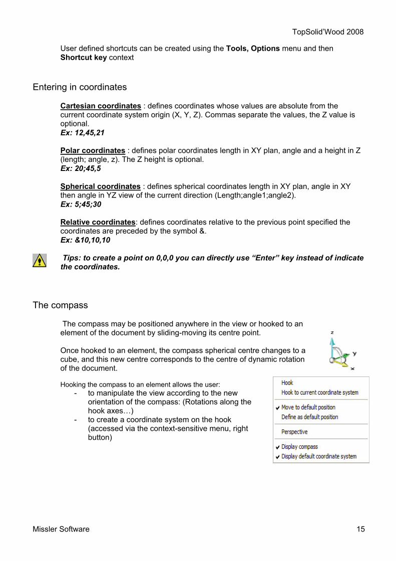
Cartesian coordinates : defines coordinates whose values are absolute from the current coordinate system origin (X, Y, Z). Commas separate the values, the Z value is optional. Ex: 12,45,21 Polar coordinates : defines polar coordinates length in XY plan, angle and a height in Z (length; angle, z). The Z height is optional. Ex: 20;45,5 Spherical coordinates : defines spherical coordinates length in XY plan, angle in XY then angle in YZ view of the current direction (Length;angle1;angle2). Ex: 5;45;30 Relative coordinates: defines coordinates relative to the previous point specified the coordinates are preceded by the symbol &. Ex: &10,10,10 Tips: to create a point on 0,0,0 you can directly use “Enter” key instead of indicate the coordinates.
The compass
The compass may be positioned anywhere in the view or hooked to an element of the document by sliding-moving its centre point. Once hooked to an element, the compass spherical centre changes to a cube, and this new centre corresponds to the centre of dynamic rotation of the document.
Hooking the compass to an element allows the user:
- to manipulate the view according to the new orientation of the compass: (Rotations along the hook axes…)
- to create a coordinate system on the hook (accessed via the context-sensitive menu, right button)

TopSolid’Wood 2008
16 Missler Software
Status bar
Provides feedback and allows the user to quickly set layers, colors etc. and set display tolerances and invisible parts. Information shown can change depending of the modules (TopSolid’Design, TopSolid’Draft …).
Click directly onto the value to change/manage it. Here is a description of some modes in the bar. (See on line help for more explanation). Mode : Allows you to change the selection method in the document. Tolerance : Determine the precision of the model (Related to both performance and file size) Magnetic snap : Allows the use of the grid points of the current coordinate system. Visibility : Controls the visualization of the parts. Material : Allows you to change the default material of the document.
Added bars
In order to reveal options for Quick layers and line styles, right-click in the menu bar.
In the menu that appears select Quick line styles and Quick layers.

TopSolid’Wood 2008
Missler Software 17
Layers management The dialog box appears when you click on “Layers” in the status bar. You have 3 different levels of layers :
- The current layer is in green. - Active layers are in red (visible). - Inactive layers are in black (invisible).
The lower part of the dialogue box gives access to several options. It is possible for example to name a layer, to freeze it (i.e. make it inaccessible), or to group or explode several layers. The groups only appear in the list and must be given a name.
Main functions
New document : There are two main types of documents : Design documents, .TOP Draft documents, .DFT
For each type you can find standard templates (1 coordinate system, 3 coordinate systems, A4, A3…). You can create your own templates and save them in your “Config | Template” folder.
Open an existing document :
TopSolid shows a list of files in the current folder with TopSolid extensions and also files supported by direct interfaces like IGES, STP, DXF, DWG, Parasolid, ACIS … Some direct interfaces are separately purchasable.
TopSolid’Wood 2008
18 Missler Software
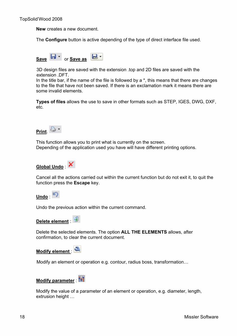
New creates a new document. The Configure button is active depending of the type of direct interface file used.
Save or Save as 3D design files are saved with the extension .top and 2D files are saved with the extension .DFT. In the title bar, if the name of the file is followed by a *, this means that there are changes to the file that have not been saved. If there is an exclamation mark it means there are some invalid elements. Types of files allows the use to save in other formats such as STEP, IGES, DWG, DXF, etc.
Print. This function allows you to print what is currently on the screen.
Depending of the application used you have will have different printing options.
Global Undo : Cancel all the actions carried out within the current function but do not exit it, to quit the function press the Escape key.
Undo : Undo the previous action within the current command.
Delete element : Delete the selected elements. The option ALL THE ELEMENTS allows, after confirmation, to clear the current document.
Modify element : Modify an element or operation e.g. contour, radius boss, transformation…
Modify parameter : Modify the value of a parameter of an element or operation, e.g. diameter, length, extrusion height …

TopSolid’Wood 2008
Missler Software 19
Insert element : Insert an element e.g. point, line, circle ...
Extract element : Extract a portion or feature of an element.(e.g.: point of a contour, drill or fillet on a shape, union, boss, title block element,...). If there is an ambiguity, TopSolid will ask you to choose between them. The element or the operation is destroyed but the elements that were used to create it are preserved. Example: the extraction of a boss eliminates the boss but not the profile from which it was generated (the profile remains invisible).
Move parents :
Move an element and its construction elements if the element is not fully constrained. TopSolid will show dynamically the possible positions.
Inserted point
Point to extract

TopSolid’Wood 2008
20 Missler Software

TopSolid’Wood 2008
Missler Software 21
2D Functions

TopSolid’Wood 2008
22 Missler Software
Bisectrix
Polar (Centered vertical)
Face
Contact angle 45° Final Point
Sketch line
Icon : Menu : Curve | Sketch line
Line
Icon : Menu : Curve | Line
Line by 2 points
Horizontal
Vertical
Angle 30°
On point
Horizontal
Vertical Angle 30°
On tangent

TopSolid’Wood 2008
Missler Software 23
Radius and Center
Point
Diameter and Center
2nd Point
1st Point
Diameter and Passing points
Rectangle
Icon : Menu : Curve | Rectangle
Circle
Icon : Menu : Curve | Circle
Rectangle created with option “DIAGONAL”
Elements to enclose
Rectangle created with option “ENCLOSING” and margin at 0
Rectangle created with X and Y dimensions
TopSolid’Wood 2008
24 Missler Software
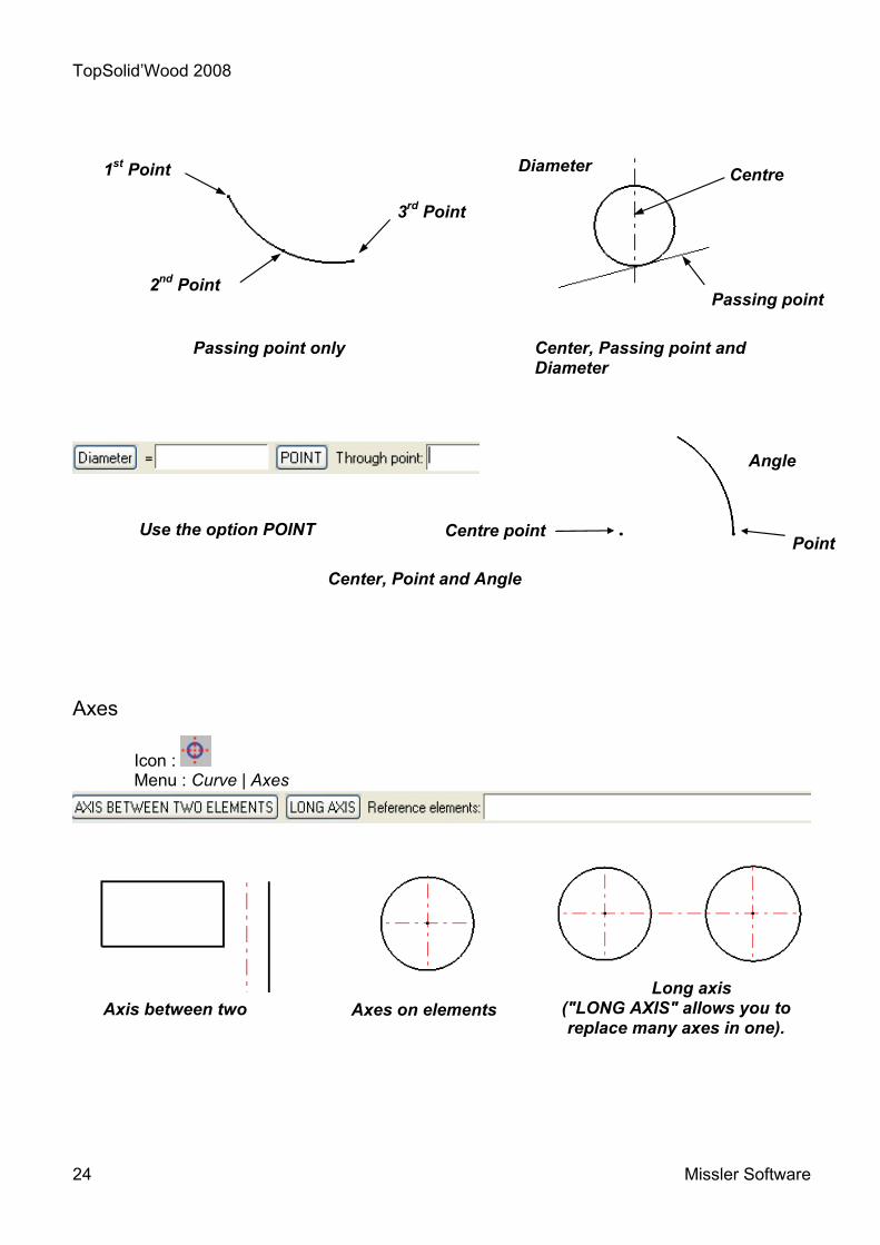
Axes
Icon : Menu : Curve | Axes
Use the option POINT Point
Angle
Centre point
Center, Point and Angle
Axis between two Axes on elements Long axis
("LONG AXIS" allows you to replace many axes in one).
1st Point
2nd Point
3rd Point
Passing point only
Centre
Passing point
Diameter
Center, Passing point and Diameter

TopSolid’Wood 2008
Missler Software 25
Offset curve
Icon : Menu : Curve | Offset curve
Thickened curve
Icon : Menu : Curve | Thicken
Reference curve
Reference curve (With the Rotative picking you can select only the arc).
Symmetric = YES Symmetric = NO

TopSolid’Wood 2008
26 Missler Software
Standard curve
Icon : Menu : Curve | Other curves|Standard curve
Create profiles from standard curves. Note: you can create your own standard curves.
Regular polygon
Icon : Menu : Curve | Other curves | Regular polygon

TopSolid’Wood 2008
Missler Software 27
Arc bend
Icon : Curve | Other curves | Arc bend
Middle curve
Icon : Menu : Curve | Other curves | Middle curve
Create a middle curve between two curves (made by lines and arcs).
Ellipse
Icon : Menu : Curve | Other curves | Ellipse
Allows the user to create an ellipse using a centre point and two passing points, or by using two focus points and a passing point.
It is possible to dimension these points.
1
2
1
2
1
2
Center point and Passing points 2 Focus points and Passing point

TopSolid’Wood 2008
28 Missler Software
Spiral
Icon : Menu : Curve | Other curves | Spiral | helix
Create spiral manage by diameter/radius, two pitches and angle with left or right way. See the two examples below :
Splines
Icon : Menu : Curve | Splines Create splines by different types of point creation.
Top view Top view
Interpolation Control
TopSolid’Wood 2008
Missler Software 29
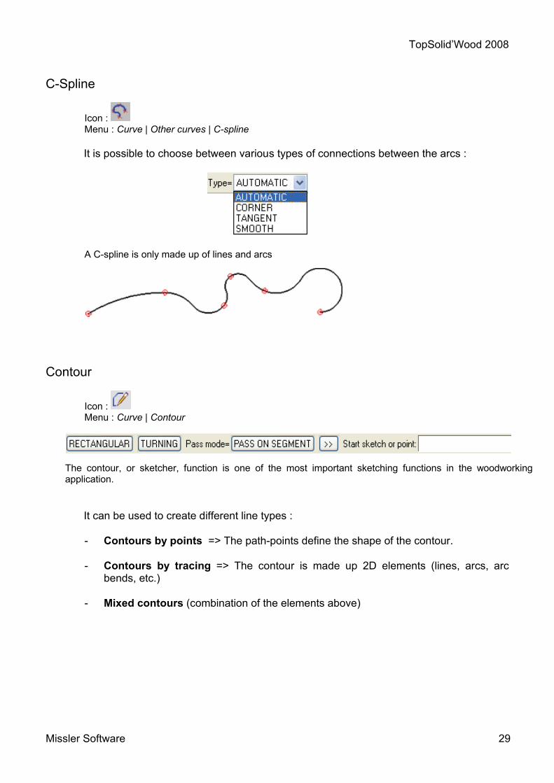
C-Spline
Icon : Menu : Curve | Other curves | C-spline
It is possible to choose between various types of connections between the arcs : A C-spline is only made up of lines and arcs
Contour
Icon : Menu : Curve | Contour
The contour, or sketcher, function is one of the most important sketching functions in the woodworking application.
It can be used to create different line types :
- Contours by points => The path-points define the shape of the contour. - Contours by tracing => The contour is made up 2D elements (lines, arcs, arc
bends, etc.)
- Mixed contours (combination of the elements above)

TopSolid’Wood 2008
30 Missler Software
TopSolid’Wood 2008
Missler Software 31
The contour function

TopSolid’Wood 2008
32 Missler Software
The contour function
The contour function is used to draw shapes composed mainly of lines and circles. This line is a single entity of segments that are connected one another and is not a juxtaposition of 2D entities (lines, circles, etc.).
In the Wood module application, creating contours (the geometry of the part to be created) is an essential step in the 3D modeling of the object. This versatile function can be used to draw most shapes. Therefore, it is important to have a strong command of this geometric tool. This function can be supplemented with the Wood functions in order to substantially simplify the drawing. There are several ways of modeling parts:
- First method : Once a simplified contour of the geometry of the required
volume has been drawn, the Wood or CAD tools (drilling, grooving, folding, forming, etc.) can be used to work the tool by removing or adding materials to obtain the required result.
- Second method : The part is modeled by drawing a precise contour of the geometry of the part and then using the Extrude function.
Both solutions are effective, offering some divergences and differing advantages.
Drawing of a contour encompassing the part to be created
10x45 chamfer
Groove with 55 offset, 25x9
Drawing of the final contour of the part

TopSolid’Wood 2008
Missler Software 33
The purpose of the operations is to significantly simplify the initial drawing and to automate the machining of the part in TopSolid’WoodCAM. For example, making a fold requires a path and a tool, while drilling requires a diameter, depth and drill axis. Creating the lines of the geometry means that complex parts can be drawn more quickly and that constraints can be applied to the dimensions in accordance with the user’s requirements.
Constraints
The contour is a function used to draw a contour point by point. TopSolid’Design automatically applies the geometric constraints in order to freeze the geometry of the drawing. There are various types of constraint. The software only creates the alignment (horizontal or vertical) and the perpendicularity constraints automatically. However, constraints can be deleted or added manually using the Tools | Constrain menu.
Note: Constraints can be identified by the following symbols. When creating a contour, the numerical values at the extremities determine:
- The relative coordinates in relation to the preceding point - The angle with the horizontal axis - The length of the segment.
When the cursor is horizontally or vertically aligned with a point, it changes shape and proposes to apply a constraint. (fig. 1)
If the waypoint is vertically or horizontally aligned with another point in the same contour, a constraint is automatically, symbolized by a grey line. (fig2)
The symmetry constraint is applied using the
wrench function on the dimension.
fig1 fig2

TopSolid’Wood 2008
34 Missler Software
Link and join
When creating the contour, the link and join options can be used if the shape to be drawn is made up of different entities (lines and arcs).
Connections between two points of a drawing are called links.
The distinction is made between lines and intersections when a contour is drawn using a 2D entity.
Connections between two links are called joins.
Intersection or line link
Tangent link 3-point arc link
Arc link
Fillet join
Chamfer join
Moving the upper right-hand point
Destruction of the two alignment

TopSolid’Wood 2008
Missler Software 35
Once the drawing is finished, these options are modified using the function. You can choose to edit the link or join of the contour depending on the selected zone.
Protractor
The advanced options, , include the PROTRACTOR option, which is used to automatically create the angular dimensions when creating the contour.
No protractor: the next line in the contour will not use the protractor and may be at any angle to the preceding line.
Incremental protractor: the next line in the contour will be built with an angular pitch relative to the preceding line.
Absolute protractor: the next line in the contour will be built with an angular pitch relative to the axes of the current coordinate.
Incremental protractor Absolute protractor

TopSolid’Wood 2008
36 Missler Software
Start point
Trace modes
When creating a contour using 2D entities, different modes can be used to limit the number of mouse clicks.
ON SEGMENTS: This is the default mode. Click on each element that you want to use in the sketch. All of the intermediate segments must be selected, even for composite lines made up of several segments, arcs or curves.
ON COMPOSITES If a composite curve is selected in this mode, the designated segment is used as the point of departure of the composite curve. Enter the segment corresponding to the sketch and the system asks for the end segment. You can then continue to draw the contour on other sketches or points.
AUTO CONTINUE Composite curves are not necessary in this mode. If using a succession of 2D entities, this mode can be used to create a contour passing through the different entities in just a few clicks, providing that the link between the entities is correct. (this is useful when importing dxf files).
Start point
End point
End point

TopSolid’Wood 2008
Missler Software 37
Dimension The final step in the construction of a contour consists in defining the dimensions using the dimension and constraint functions.
Points that are not dimensioned or constrained are free to move in the coordinate in which they were created. A poorly dimensioned contour can be easily deformed if the user does not check it or define sufficient dimensions. The problem is to understand how contours are properly dimensioned. Too many dimensions will apply too many constraints to the drawing, while insufficient dimensions will result in incorrect drawings. Dimensions can be applied to the curve below in different ways. The color of the dimensions changes depending on the order in which they are created. - Active dimensions (green) can be modified and change the contour. - Passive dimensions (yellow) cannot be modified and are the result of additional
constraints. They are automatically deactivated by the software to prevent conflicts.
In simple cases, the software automatically creates passive dimensions. More complex cases many contain an excess of active dimensions and consequently apply too many constraints to the contour. The role of this function is to impose dimensions. Therefore, they must not be deleted, once the dimensions of the contour are correct.
To apply a dimension, simply designate the corresponding points or lines. The ends of the arrows change, depending on whether the dimensions are applied to lines or points.
PARALLEL HORIZONTAL VERTICAL

TopSolid’Wood 2008
38 Missler Software
In the FREE mode, one of the three modes above can be selected, depending on the position of the cursor.
To apply dimensions to an angle, enter two lines. One of the four cases below is obtained, depending on the position of the cursor when validating.
Modifying dimensions The software contains two functions for modifications:
- Modification of elements Edit | Modify Element.
- Modification of parameters Parameter | Modify. The function must be selected according to the element to be modified, since the functions cannot be used to modify the same items.
Use the function to modify dimensions. This function modifies numerical values, such as the value of a drill hole diameter.
Use the function to modify an option or a physical characteristic of an element. This function can be used to change the type of hole, to switch between a line and an arc or to edit an operation.
Dependencies between dimensions
Each dimension is independent. Only the values of the selected dimension are modified.

TopSolid’Wood 2008
Missler Software 39
The dimension to be changed is indicated by a red highlight. There are no links between the dimensions and they can all be modified independently.
Dependencies can be created between dimensions, in which case modifying one dimension will also modify all the linked dimensions.
The Parameter | Merge function is used to make two dimensions identical. Enter the reference dimension to be applied and the dimension to be modified.
A red highlight is used to check the dimensions to be modified.
Parameters
The notions of dependencies above are not enough for the effective design of a project. For example, how can the thickness of a base be made half that of a panel? Parameters are used to answer this question. If the term “th” is the thickness of the panel, then the term “th/2” is the thickness of the base. Parameters are created using the Parameter | Create function. Select the unit, value and name. The default unit is length in mm. Parameters can also be created for angles, numbers, volumes, etc.
Use the function to apply a parameter to a dimension. Then enter the name of the parameter in the Replacement Parameter cell using the REPLACE option.

TopSolid’Wood 2008
40 Missler Software
Equations can also be entered in this cell.
Types of contours
The notions explained above are the options of the contour function. The following drawing methods can be used, depending on the part to be modeled. The same method is not used to draw a cupboard or the foot of a unit.
Point by point contour The drawing of the contour is defined by the different waypoints and the dimensions are used to size the part.

TopSolid’Wood 2008
Missler Software 41
Traced contours
Traced contours are built by taking an existing geometry (lines, arcs, sketches, etc.) and creating the corresponding shape.
Mixed contours (combination of the elements above) The two preceding methods can be combined in a single contour.

TopSolid’Wood 2008
42 Missler Software
Points
Some functions use passing points (center point of circle, starting point …), and you need to create them if they don't exist. The Tools | Points menu includes a list of geometric points that can be used to create the points.
You can create points in two ways : - Create the point before using a function.
Open the Tools | Points menu, then select a point from the list. You can also click on the icon and select a point from the list of special points.
This icon bar matches the list of points in the Tools | Points menu below.
- Create the point on the fly while using the function.
When the function asks for a point, you can use the shortcut to create the point and then resume use of the function.
You can combine several creations of points. For example, create the middle point of two center points. Certain points are used frequently.
You must be able to create the following points in particular :
Cartesian point
Offset point
Middle point
Center key point
Curve-curve intersection point
Point on curve
Replica point

TopSolid’Wood 2008
Missler Software 43
Example of use of points.
Cartesian points: are used to create points using the three X Y Z coordinates of the current reference.
Only the X and Y dimensions appear on the screen.
Offset points: are used to create points that are offset from a reference point. Points can be offset in a different direction from the axes of the reference.
Middle points: are used to create a point in the middle of two points.
Key : Original point Point created

TopSolid’Wood 2008
44 Missler Software
Center key points: are used to create a point in the center of an element (curve, edge, etc.). Entering a line when creating a center point selects the middle of the line.
Curve-curve intersection point: is used to create an intersection point between two curves or edges. This type of point can be retrieved by pressing and holding the left-hand mouse button.
Point on curve: is used to create a point on a curve. (5 types of position - Designation, Start, Middle, End, Constraint). Different types of length can be processed in constrained mode.
All of the points above remain associated with their point of origin when created.

TopSolid’Wood 2008
Missler Software 45
Simple shapes

TopSolid’Wood 2008
46 Missler Software
Extruded
Icon : Menu : Shape | Extruded
This function is used to created surface or volume shaped by extruding a contour or a surface. The contour can be open or closed.
Open contours produce surfaces, while closed contours produce solids.
Extruded shapes can be made using the advanced options :
- by imposing a direction of extrusion. (enter an axis) - with an offset extrusion curve (upwards or downwards). - by automatically giving a draft angle all the surfaces of the solid.
NORMAL alignment CENTERED alignment
Extrusion of a surface Selection of several curves
Extrusion in a direction
Extrusion with taper angle
Extrusion with offset distance
TopSolid’Wood 2008
Missler Software 47
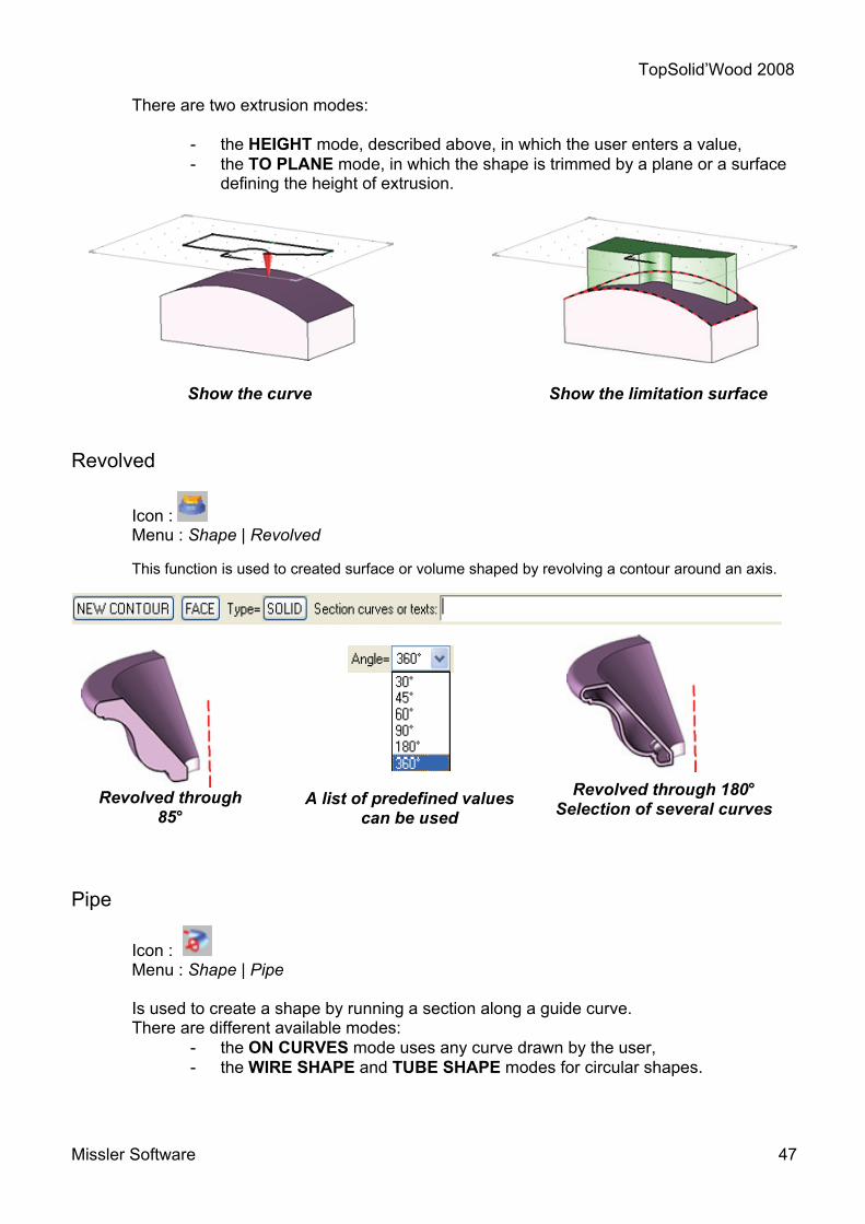
There are two extrusion modes:
- the HEIGHT mode, described above, in which the user enters a value, - the TO PLANE mode, in which the shape is trimmed by a plane or a surface
defining the height of extrusion.
Revolved
Icon : Menu : Shape | Revolved
This function is used to created surface or volume shaped by revolving a contour around an axis.
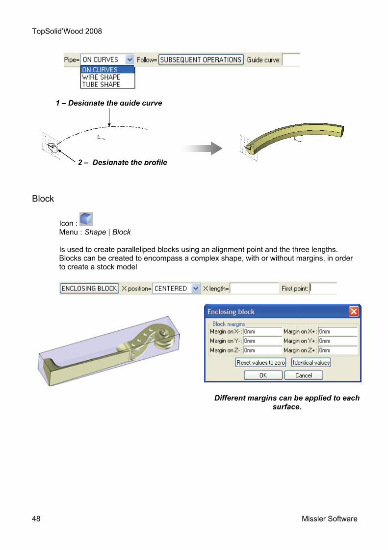
Pipe
Icon : Menu : Shape | Pipe Is used to create a shape by running a section along a guide curve. There are different available modes:
- the ON CURVES mode uses any curve drawn by the user, - the WIRE SHAPE and TUBE SHAPE modes for circular shapes.
Show the curve Show the limitation surface
Revolved through 180° Selection of several curves Revolved through
85° A list of predefined values
can be used
TopSolid’Wood 2008
48 Missler Software
Block
Icon : Menu : Shape | Block
Is used to create paralleliped blocks using an alignment point and the three lengths. Blocks can be created to encompass a complex shape, with or without margins, in order to create a stock model
1 – Designate the guide curve
2 – Designate the profile
Different margins can be applied to each surface.

TopSolid’Wood 2008
Missler Software 49
Height
1st Point2nd Point
Alignment point
Cylinder
Icon : Menu : Shape | Cylinder Used to create solid, cylindrical shapes. You can create:
- Using two waypoints - Or a length and its direction
Cone
Icon : Menu : Shape | Other shapes | Cone Used to create two types of cone: POINTED or TRUNCATED
Different values can be adjusted for truncated cones.
Sphere
Icon : Menu : Shape | Other shapes | Sphere Used to create spheres. The radius or diameter can be set.

TopSolid’Wood 2008
50 Missler Software

TopSolid’Wood 2008
Missler Software 51
Complex shapes

TopSolid’Wood 2008
52 Missler Software
Ruled
Icon : Menu : Shape | Other shapes | Ruled Used to create a ruled surface or a solid between two curves or a curve and a point. See notion of the origin of contours.
Swept
Icon : Menu : Shape | Other shapes | Swept
Similar to the Pipe function, the Tube function offers more options, especially with regard to the choice of sections and guide curves (selection of several sections and guide curves, check sweep of the section in relation to the guide curve)
All types of complex surfaces can be created using these three modes.
Shape ruled on contour and pointShaped ruled on two contours

TopSolid’Wood 2008
Missler Software 53
Multi-criteria selection.
By default, the selection icon is inactive. It becomes active in certain CAD functions and you can enter one or more entities:
- manually, by designating them in the 3D document - according to physical criteria (color, layer, by box, etc.).
This function may be useful to change the color or the line type of several 2D entities and to repeat several parts.
Clicking on the selection icon opens a new tool bar that includes a range of options that can be used to select the elements you need.
The bar is divided into two zones. The first is the 3-mode selection zone: Add, Filter, Remove.
The second zone is for the selection criteria. Examples of selection criteria :
By type of part: (Shape, Contours, Parts, Points, References, etc.)
By layer (select all the elements in a given layer).
By physical criteria, superior or inferior.
A report in the alphanumerical bar indicates the number of selected elements.

TopSolid’Wood 2008
54 Missler Software

TopSolid’Wood 2008
Missler Software 55
Control elements, display and layers
TopSolid’Wood 2008
56 Missler Software
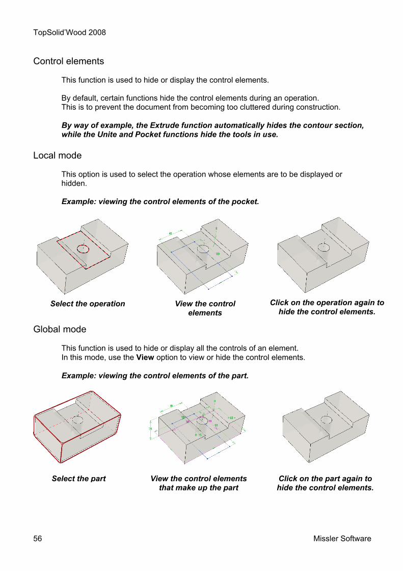
Control elements This function is used to hide or display the control elements. By default, certain functions hide the control elements during an operation. This is to prevent the document from becoming too cluttered during construction. By way of example, the Extrude function automatically hides the contour section, while the Unite and Pocket functions hide the tools in use.
Local mode
This option is used to select the operation whose elements are to be displayed or hidden. Example: viewing the control elements of the pocket.
Global mode This function is used to hide or display all the controls of an element. In this mode, use the View option to view or hide the control elements. Example: viewing the control elements of the part.
Select the part View the control elements that make up the part
Click on the part again to hide the control elements.
Click on the operation again to hide the control elements.
Select the operation View the control elements

TopSolid’Wood 2008
Missler Software 57
Display
The display can be configured and adjusted for both the appearance of the 3D rendering (wire mode, shaded, realistic), the zoom and the working windows. Click on the Rendering icon to open the list of views. The main display categories are shown below.
Click on the Rendering icon to open the list of types of rendering. Along similar lines, there are also pallets for colors and types of lines and points. Multiple selections can be used to edit several entities at the same time.
There are two pallets for zooms and views.
SynthetiRealistic Wire d
Shaded
Rendering Colors
Line types
Point types
Top view
Perspective
Configure view
Orientate view
Share view
Delete view
Vertical mosaic
Horizontal mosaic
Views
Zoom in
Zoom out
Zoom on item
Zoom 100%
Zoom on current coordinate system
Undo zoom Zooms

TopSolid’Wood 2008
58 Missler Software
Layers
Quick layers can be used to draw on the screen as is you were using several overlays. By default, there are 15 layers. The number of layers can be increased to 1,000, numbered from 0 to 999, using the Tools|Options|Icon bars command. You can make one or more layers active or inactive at any time. This action makes the elements associated with the corresponding layer visible (active) or invisible (inactive). This action is similar to adding an overlay onto a drawing board. When creating a new document, by default TopSolid’Wood assigns a current layer (0). This layer is green and is visible in the quick layers bar and the status bar.
« All created elements are stored in the active layer » Example :
When layer 1 is activated, the block reappears and layer 2 remains the current layer
Block inserted on the current layer (1)
Sphere insert on the current layer (2). Layer 1 is inactive
Current layer
Status bar
Quick layers bar
Active layer

TopSolid’Wood 2008
Missler Software 59
Quick layers bar
The quick layers bar is used for quick and easy layer management. The left-hand mouse button activates the selected layer (red). The middle mouse button makes the selected layer the current layer (green). The right-hand mouse button opens the dialog box shown below.
Layer editor
The layer editor is used to view all of the layers and to perform a number of operations (Group, Freeze, Activate, etc.).
Open the editor by clicking on the Layers tab in the status bar.
Refer to the on-line help for more details.
This field is used to change the number of the selected layer.
This field is used to name the selected layer.
Ticking this box makes the selected layer active and current
Ticking this box makes the layer active

TopSolid’Wood 2008
60 Missler Software

TopSolid’Wood 2008
Missler Software 61
Operations

TopSolid’Wood 2008
62 Missler Software
Drilling
Icon : Menu : Shape | Drilling Is used to place drill holes on the shapes.
There are three ways of positioning a drill hole:
- DYNAMIC: the software automatically places the axis of the drill hole in relation to the edges
- NON-DYNAMIC: the user enters the position of the drill hole in relation to the edges. In certain cases, a dimension appears in yellow to indicate that the drill hole is centered on the support surface of the part
- REFERENCE: in some cases, when the surface to be drilled is not flat, a coordinate reference must be used to position the axis of the drill hole.
Examples of possible positions of the drill hole on the surface :
Drilling templates are essential when using the multi-drilling function in the Wood menu.
Drill hole concentric with the circular edge
Drill hole centered in relation to the width and length of the support surface (yellow
dimension)
Drill hole that can be positioned in relation to the
width and length of the shape (green dimensions)
The REFERENCE function is used to drill on uneven surfaces

TopSolid’Wood 2008
Missler Software 63
Icon : Menu : Shape | Pocket
Is used to remove material from solid shapes using a closed contour.
Boss
Icon : Menu : Shape | Boss
Is used to add material to solid shapes using a closed contour.
For both of these functions, the contour must be in a plane that is parallel to the surface to be changed. Depth is measured from the surface.
The CONTOUR IN PLACE option means that the contour defines the height of the operation. This option is used to perform these operations on uneven surfaces.
TopSolid’Wood 2008
64 Missler Software
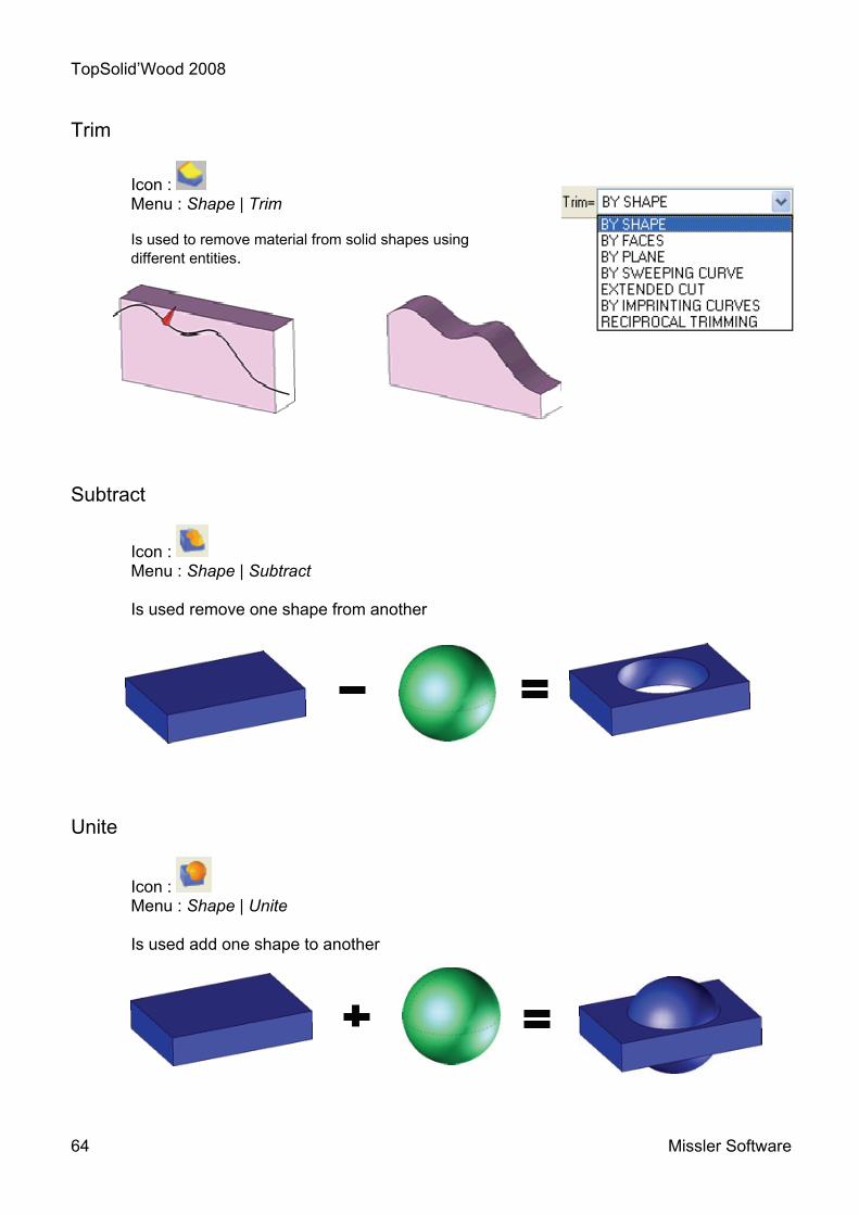
Trim
Icon : Menu : Shape | Trim
Is used to remove material from solid shapes using different entities.
Subtract
Icon : Menu : Shape | Subtract Is used remove one shape from another
Unite
Icon : Menu : Shape | Unite Is used add one shape to another

TopSolid’Wood 2008
Missler Software 65
Intersect
Icon : Menu : Shape | Other Operations | Intersect Is used to obtain the intersection of several shapes.
Fillet
Icon : Menu : Shape | Fillet Creation of constant or variable fillets. It is possible to create rounded corners.
Chamfer
Icon : Menu : Shape | Chamfer Is used to create chamfers on the edges of volume parts.
Chamfers can be created with one length and an angle or with two lengths.
Draft
Icon : Menu : Shape | Draft
Is used to apply draft angles to one or more surfaces of a solid shape.
The surfaces must be flat, cylindrical or conical. It is possible to create draft angles with flat planes.

TopSolid’Wood 2008
66 Missler Software
Shell
Icon : Menu : Shape | Other Operations | Shell
Is used to transform a solid into a shell by removing the surfaces.
Threading
Icon : Menu : Shape | Other Operations | Threading Is used to thread cylindrical parts to different standards.
A conical thread can be created on a conical or cylindrical shape by selecting the standard "Gas with seal".
Groove
Icon : Menu : Shape | Other Operations | Groove Is used to create grooves on cylindrical surfaces.

TopSolid’Wood 2008
Missler Software 67
Propagation of operations Example with a drilled hole.
Circular propagation
Plane symmetry
On curve
Linear propagation
Matrix propagation
By coordinate system
Spiral propagation Sum total of propagations
Rectangular propagation
Double plane symmetry
Propagation by circular translation
Multiplication of propagations

TopSolid’Wood 2008
68 Missler Software
Propagations can be applied to the following operations :
Propagations can be modified by removing certain occurrences :
EXCLUDE BY MANUAL SELECTION : BY CLOSED CONTOUR
• drilling
• pockets
• bosses
• ribs
• grooves
• slots
• subtractions
• unions
• trimming
• contours
• slots
• folds
• sawing
• turning
• tenon
• mortise
• fitting
TopSolid’Wood 2008
Missler Software 69
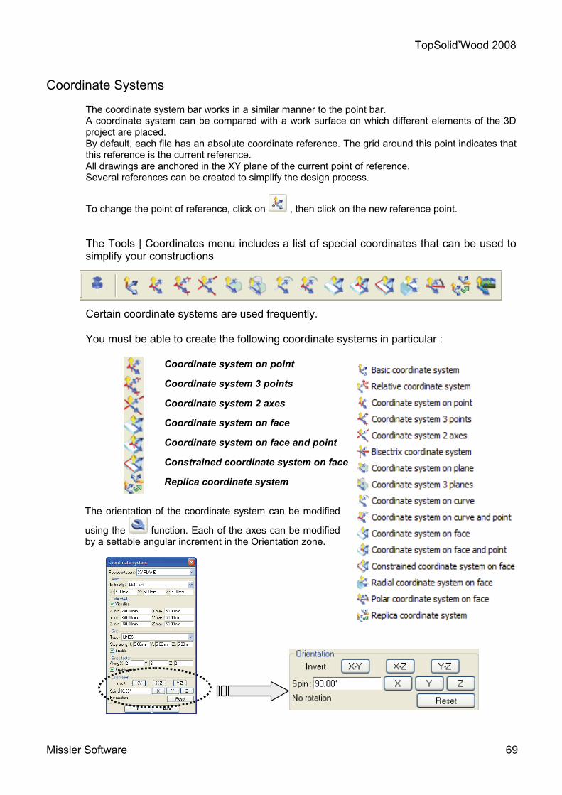
Coordinate Systems
The coordinate system bar works in a similar manner to the point bar. A coordinate system can be compared with a work surface on which different elements of the 3D project are placed. By default, each file has an absolute coordinate reference. The grid around this point indicates that this reference is the current reference. All drawings are anchored in the XY plane of the current point of reference. Several references can be created to simplify the design process.
To change the point of reference, click on , then click on the new reference point. The Tools | Coordinates menu includes a list of special coordinates that can be used to simplify your constructions
Certain coordinate systems are used frequently. You must be able to create the following coordinate systems in particular :
Coordinate system on point
Coordinate system 3 points
Coordinate system 2 axes
Coordinate system on face
Coordinate system on face and point
Constrained coordinate system on face
Replica coordinate system
The orientation of the coordinate system can be modified
using the function. Each of the axes can be modified by a settable angular increment in the Orientation zone.

TopSolid’Wood 2008
70 Missler Software
Examples of the use of coordinate systems
Coordinate system on point: Coordinate systems on points retain the orientation of the current coordinate system on which it depends when positioned on the designated point.
Coordinate system 3 points: Coordinate systems 3 points are oriented using waypoints. The first point defines the origin 0 of the coordinate system, the second defines the position of the point for the X axis and the third defines the point for the Y axis.
Coordinate system 2 axes If there are more than two contours, the X+ and Y+ directions of the coordinate system are defined. The arrows indicate the positive direction of the axes.

TopSolid’Wood 2008
Missler Software 71
Coordinate system on face: Creates a coordinate system positioned in the center of the selected surface. Warning: the coordinate system is positioned in the center of the face at the time it is created, but it is not constrained. Changes to the geometry may cause the coordinate system to move.
Coordinate system on face and point: Creates a coordinate system whose orientation can be controlled using a reference surface and whose position can be controlled using a point.
Constrained coordinate system on face: Is DYNAMICALLY placed on the selected surface. Behaves like a drill hole by positioning itself in relation to the nearest edges (green dimensions).
Depending on the position, it is automatically centered on the surface (yellow dimensions).
A coordinate system with two yellow dimensions is centered in relation to the length and
width of the surface.

TopSolid’Wood 2008
72 Missler Software
A single yellow dimension indicates that the system is centered in relation to one of the sides.
Replica coordinate system: Creates a coordinate system by transformation in the same manner as the duplication and repetition functions.
To change the orientation of a coordinate system manually, select the system, click
on and change the orientation of the axes.
Use the current coordinate system function to make a system the current system.
Constrained coordinate,
centered on the f
Coordinate constrained in relation to the
edges
Constrained coordinate, coaxial with the circular
edge

TopSolid’Wood 2008
Missler Software 73
Memo : Duplicate – Repeat

TopSolid’Wood 2008
74 Missler Software
There are two ways to copy parts: DUPLICATE and REPEAT.
Duplicate
This function is used to create one or more identical copies that are associated with the original.
This function cannot be used to control the setting of the number of copies.
Each duplicate part is linked to the original template. The direction of the link is one-way: from the template to the copy.
Subsequent operations
When this option is used, any operations performed on the Template are automatically applied to the duplicates.
If a chamfer is created on the template, it is automatically created on the different copies by the link.
Template
Three duplicates
1
2
3
Template

TopSolid’Wood 2008
Missler Software 75
Template
Template
Modified part.
On the other hand, operations performed on the copies are not applied to the template.
Making changes to a copy does not break the link with the template.
However, it is possible to break the link.
Select the icon, then click on a copy to deactivate the link. Use the FOLLOW EXISTING OPERATIONS option.
Changes to the template will be applied to the copies using the active links.
Existing operations
This option is used to perform operations on the template without changing the copies.
If a chamfer is created on the template, the copies remain unchanged because the link is inactive
Once the link has been broken and the template has been modified, the mode can no longer be changed.
Template
Links deactivated on this copy.

TopSolid’Wood 2008
76 Missler Software
Use in the BOM
All duplicated parts are linked geometrically but can be defined independently. Each part has its own data (designation, material, dimensions, etc.).
TopSolid’Wood 2008
Missler Software 77
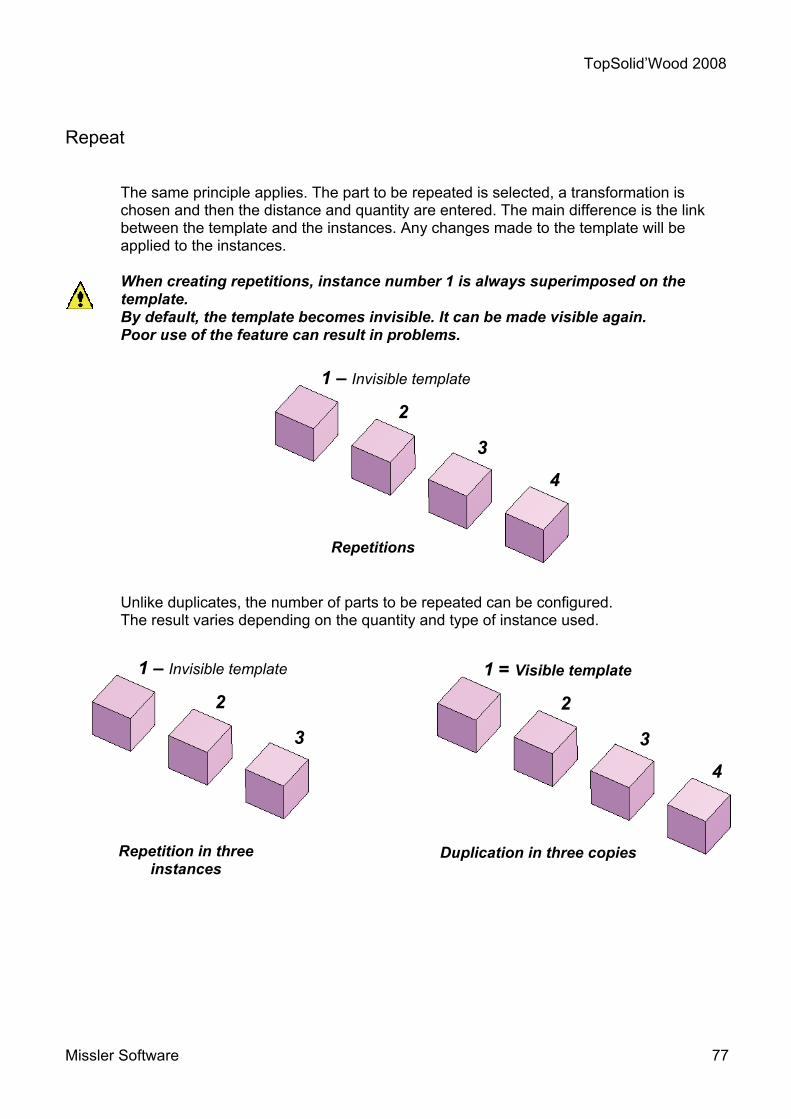
Repeat
The same principle applies. The part to be repeated is selected, a transformation is chosen and then the distance and quantity are entered. The main difference is the link between the template and the instances. Any changes made to the template will be applied to the instances.
When creating repetitions, instance number 1 is always superimposed on the
template. By default, the template becomes invisible. It can be made visible again. Poor use of the feature can result in problems.
Unlike duplicates, the number of parts to be repeated can be configured. The result varies depending on the quantity and type of instance used.
Repetitions
1 – Invisible template
2
3
4
Repetition in three instances
1 – Invisible template
2
3
Duplication in three copies
1 = Visible template
2
3
4

TopSolid’Wood 2008
78 Missler Software
Two distribution modes are available for repetitions :
Total distance :
The value is the distance "l" between the template and the furthermost instance. The number of instances is spread across a distance.
Distance per instance
The value is the distance between two instances. A distance and a number are imposed.
There are two ways to edit the template: the construction tree or the wrench.
Using the construction tree Open the construction tree and Edit the repetition. This function is easy to use:
- if the INSTANCES are in bold type face, then the template is invisible, - if the TEMPLATE is in bold type face, then the instances are invisible.

TopSolid’Wood 2008
Missler Software 79
To make the template visible or invisible, right-click on the line that identifies the repetition. In the drop-down list, select Template = INVISIBLE to hide the template and the reverse to view it.
You must be in visibility mode
Invisible=Hidden. In this way, you will not mix up
the template and the repeated instances.
Using the wrench
Start the Modify element function . Select one of the repeated instances, then select the EDIT TEMPLATE tab to view the template.
Repetition
1 – Invisible template
2
3
4
Template – 1 invisible
Repetition invisible

TopSolid’Wood 2008
80 Missler Software
Use the Repeat function to return to the repetition. Select the SHOW REPETITION, then show the template. A selection filter can be used to designate just the templates.
Excluding instances of a repetition
The repetition function creates a set of repeated instances. Once or more of these instances can be excluded.
To exclude the unwanted instances, use the wrench and show the repetition. Select PROPAGATION, then EXCLUDE INSTANCE.
Show the instances to be excluded.
Repetition
1 – Template invisible
2
3
4
Template – 1 invisible
Repetition invisible
Selected instances Excluded instances

TopSolid’Wood 2008
Missler Software 81
Click on OK.
The excluded parts are not deleted. To return the parts, follow the same procedure as above and select RETURN INSTANCES.
Modifying the template
If the template is modified by an operation such as drilling, this operation appears on all the repeated instances.
Operations on repetitions
On the other hand, if the operation is performed on one of the repeated instances, it is not applied to the others. The log file indicates which instance has been changed.
1
2 – Modified
3
4
Template
Repetitions

TopSolid’Wood 2008
82 Missler Software
Use in the BOM
All of the parts in a repetition are considered to be identical.
Any changes made to the data defined for the template (designation, material, dimensions, etc.) are automatically applied to the instances.

TopSolid’Wood 2008
Missler Software 83
Memo : Different assembly methods

TopSolid’Wood 2008
84 Missler Software
Introduction
TopSolid’Design is a software used to design 3D projects 3D. Unlike in other software applications, it is possible to choose between different design methods when building the project.
The design method can be managed according to the project in order to simplify and optimize the work in hand. The two main design methods are:
- Design in place.
- Design by reassembly.
These two methods offer a close fit and offer users increased flexibility and power. Fundamentals.
Design in place.
The principle of design in place consists in creating the project in a single
document. All parts are designed in the same file.
Dimensions and constraints are used to position the parts in relation to one another. The result is an assembly of several parts.
Design by reassembly consists in creating a project by assembling several files. Users can use one of two methods to assemble the parts in the file:
- With positioning constraints.
- With key points.
The resulting file contains an assembly that refers to several other files.
Design by reassembly.
Assembly in a new file Assembly in a new file

TopSolid’Wood 2008
Missler Software 85
Designing a project
The choice between design in place and reassembly depends on the complexity and the usage of the elements to be drawn. For the following project, we need to think about the different subassemblies of the unit. In this example, the unit will be broken down into two main subassemblies :
- a box made up of:
- four plated panels with 4/10 edges. - dowels. - cams. - casters.
- Three drawers made up of:
- a box with a grooved base. - one pair of runners with retaining screws. - one wooden front panel. - one handle.
This analysis gives us an idea of the design method to be used for each of the subassemblies. The drawers will be drawn in a separate file and will then be inserted by reassembly, which means that they can be used in a future project.
Choosing the design method for the drawers
The drawers can be drawn in a single file or built from the different parts (runners, front panel, handle, screws, box). If the component parts of the drawers can be used in other projects, then it is advisable to draw them in separate files and then assemble them. This is the case of the handle and the sliders. The drawer box will be drawn in a single file. The design in place and reassembly methods can be used in the same project. There is no need to exclude one method in favor of the other. You simply need to understand the advantages of each method when making your choice. Design in place is the simpler design method, since all of the parameters are contained in a single file, a fact that simplifies the relationships between the parts. However, colors, visibility and layers must be carefully managed in order to keep the number of elements in the file under control. Design in place can be used to break down the project into subassemblies, which can be used in other projects, or to simplify the application of a project. The following diagram proposes a design process that uses the design in place method and component reassembly

TopS
olid
’Woo
d 20
08
86
Mis
sler
Sof
twar
e
The
draw
er is
ass
embl
ed u
sing
the
diffe
rent
com
pone
nts
in th
e dr
awer
fil
e.
Uni
t cre
ated
from
the
box
and
draw
er
inse
rt th
ree
times
.
Exp
lode
d vi
ew o
f the
3D
pro
ject
Dra
ft do
cum
ents
. Bi
ll of
mat
eria
ls (E
xcel
or d
raft)
.
Des
ign
by re
asse
mbl
y
Des
ign
in p
lace
.
The
box
is d
esig
ned
in p
lace
. The
fit
tings
are
inse
rted
in th
e bo
x fil
e.
3D fi
les
can
be u
sed
to c
reat
e la
rge
quan
titie
s of
doc
umen
ts: d
rafts
, pro
gram
s,
anim
atio
ns,e
tc.

TopSolid’Wood 2008
Missler Software 87
Workshop : Creation of a circular rail
On this workshop you will be able to learn to : • Use 2D sketches, • Use points and coordinate systems, • Extrude with offset and draft angle, • Create operations on shape (trim, subtract …), • Propagate an operation

TopSolid’Wood 2008
88 Missler Software
A B
Circular rail - Rail's design
1 Open a new design document Choose Without Template in the proposed list of New Document template models.
2 Create a rectangular contour Curve \ Contour \ Rectangular Draw a RECTANGULAR Contour using AUTO DIMENSION.
3 Add constraints Use the Modify element function to add a symmetry constraint on the X axis then on the Y axis. Select the dimension to constrain, click on CONSTRAIN then click on the axis to use.
4 Modify parameters Parameter | Modify parameter Modify the dimensions as above.
5 Offset points Tools | Points | Offset point
Create two points, A and B, with an offset of 19mm along Y+ axis. (See below).
TopSolid’Wood 2008
Missler Software 89
C
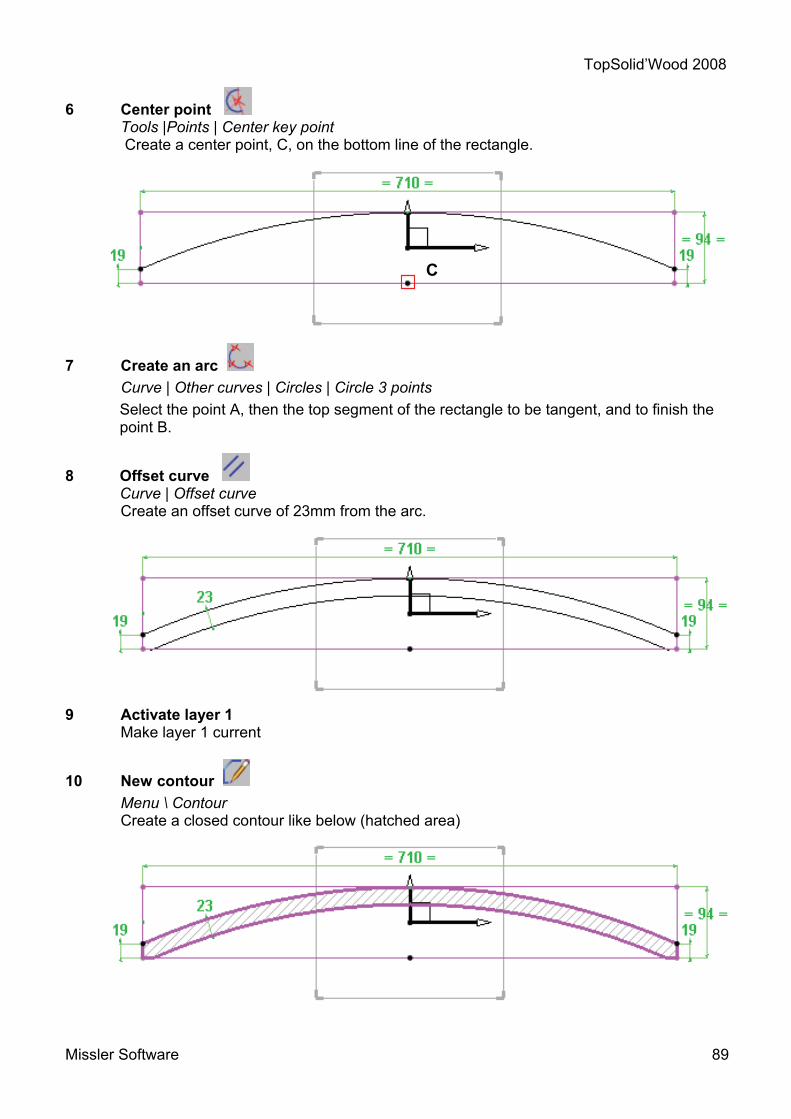
6 Center point Tools |Points | Center key point
Create a center point, C, on the bottom line of the rectangle.
7 Create an arc Curve | Other curves | Circles | Circle 3 points
Select the point A, then the top segment of the rectangle to be tangent, and to finish the point B.
8 Offset curve Curve | Offset curve
Create an offset curve of 23mm from the arc.
9 Activate layer 1 Make layer 1 current
10 New contour Menu \ Contour
Create a closed contour like below (hatched area)

TopSolid’Wood 2008
90 Missler Software
Creation of the rails
11 Extrude Shape | Extruded
Extrude the contour along Z- axis with a height of 130mm
12 Activate layer 2 Make layer 2 current
13 Coordinate system Tools | Coordinate systems | Coordinate system 2 axes Click on "Passing point" and select the C point created previously. Select X+ axis to define X axis, and Z+ axis to define Y axis. Set current this new coordinate system.
14 Offset points Tools | Points | Offset point
Create two offset points: One along Y- axis with an offset of 110mm from the current coordinate system. One along X- axis with an offset of 60mm from the offset point just created.
15 Middle point Tools | Points | Middle point
Create a middle point between the point 1 and the point 2.
21

TopSolid’Wood 2008
Missler Software 91
16 Sketch lines Curve | Sketch line Create two sketch lines: Passing by the point 1 Passing by the point 2.
17 Trim a segment Curve | Trim
Trim both sketch lines by the left border edge of the rail. Select a line, select the edge and then click on "Make trim".
18 Create arcs Curve | Other curves | Circles| Circle 3 points Select the point 1, then the top sketch line to be tangent and finally the point 2.
Select the point 2, then the bottom sketch line to be tangent and to finish the point 3.
1
2
Edge to use Result
1
2 2
3

TopSolid’Wood 2008
92 Missler Software
A
B
19 Contour Curve | Contour Create a new contour through arcs and sketch lines, starting from the point A and finishing on point B.
20 Pattern Curve | Pattern A pattern allows to duplicate a curve and sew the result as a single curve. Select the contour and choose a simple mirror using YZ plane.
21 Trim Shape | Trim In the combo list "Trim", select "By sweeping curve". Select the rail and then the trimming contour.
The red arrow shows the side to remove. Select OK. 22 Activate layer 3 Make layer 3 current

TopSolid’Wood 2008
Missler Software 93
Blind dovetail
23 Rectangular contour Curve | Contour Create a rectangular contour near the top left of the rail and use "Auto dimension".
24 Dimensions Tools | Dimension Adjust dimensions and position the contour like shown, 3mm from the top and 5mm from the left outside of the rail.
25 Fillet Curve | Fillet Use the "Local" mode to create fillets of 7.5mm on the rectangle.
26 Extrude Shape | Extruded Extrude the contour along Z+ with an offset of -10mm, a draft angle of 10° and a height of 15mm. Note: to manage the draft angle and the offset, use advanced options
27 Subtract Shape | Subtract
Select the rail and use the extruded shape as tool.
28 Propagate an operation Shape | Subtract
Select the subtraction operation just done. Select in the list of propagation "Multiplication of propagations".
- Propagation n°1 : Use "Linear" along Y- axis. Click on "Total distance" to switch to "Distance per instance" of 26.5mm and a total number of 4.
- Propagation n°2 :
Use "Simple mirror" and select YZ plane.
Select STOP.

TopSolid’Wood 2008
94 Missler Software

TopSolid’Wood 2008
Missler Software 95
Workshop : Creation of an easel
In this workshop you learn to : • Use various geometry tools, • Create a thickened profile, • Use the various points and coordinate systems, • To create a tenon / mortice assembly, • To repeat parts

TopSolid’Wood 2008
96 Missler Software
Create the geometry of the easel
1 Open a new design document Choose Without Template in the proposed list of New Document template models.
2 Create a rectangular contour Curve \ Contour \ Rectangular Draw a RECTANGULAR Contour and then click on AUTO DIMENSION.
3 Add constraints Use the Modify element function to add a symmetry constraint on the X axis, and then on the Y axis. Select the dimension to constrain, click on CONSTRAINT then click on the axis to be used.
4 Modify parameter Parameter \ Modify
Replace the dimension values with the parameters created (Shown above).
5 Create a centre point Tools \ Point \ Centre key point
Create a centre point on the upper segment of the rectangle.
6 Create a line Curve\ Line
Draw a line using the previously created centre point as the starting point of the line.
7 Dimension a contour Tools \ Dimension
Dimension the line as shown opposite. Its length will be 240 mm and its slope 75°.

TopSolid’Wood 2008
Missler Software 97
B
8 Thicken a line Curve \ Thickened curve
Thicken the previously created line using the Symmetric = YES mode and a value of 12.5 mm. From the list of End Types, select the CIRCLES INSIDE mode.
Select OK.
9 Create a contour Curve \ Contour
Draw a closed contour as shown opposite. (Contour surrounding the hatched zone)
10 Activate layer 1 Make layer 1 current.
11 Create a point on a curve Tools \ Point \ Point on curve
Using the CONSTRAINED POINT mode, create a point on curve B at a distance of 50 mm starting from point A.
12 Create a line on curve Curve \ Other curves \ Line on curve
On the line shown opposite, create a line on the curve with a CENTERED alignment, a length of 25 mm, in the PERPENDICULAR mode and using the previously created point on a curve (B).
A
Reference curve
Reference curve

TopSolid’Wood 2008
98 Missler Software
13 Create an offset curve Curve \ Offset curve
Create an offset curve, offset by 150 mm from the previously created line on a curve.
14 Trim a curve Curve \ Trim
Trim the curve as shown below.
15 Thicken a line Curve \ Thickened curve
Thicken the two lines previously created using the Symmetric = YES mode and a value of 25 mm. From the list of End Types, select the LINES mode. To modify the thickening direction, click on the red arrow on the screen.
Select OK.
Trimming curve
Curve to trim
Result

TopSolid’Wood 2008
Missler Software 99
16 Create a rectangular contour Curve \ Contour \ Rectangular
Draw a RECTANGULAR Contour using AUTO DIMENSION with length 27 mm and height of 20 mm.
17 Add constraints Use the Modify element function to add a symmetry constraint on the X axis. Select the dimension to be constrained, click on CONSTRAINT and then select the axis to use.
18 Dimension a contour Tools \ Dimension
Dimension the contour to 40 mm from the end of the mounting as shown opposite.
19 Activate layer 2 Make layer 2 current
Model the easel
20 Extrude Shape \ Extruded
Extrude the 3 contours corresponding to the cross-pieces, with a value of 128 mm in the Z- direction.

TopSolid’Wood 2008
100 Missler Software
Tenon the cross-pieces
21 Tenon Wood \ Tenon
Create a horizontal tenon on one of the three cross-pieces. A tenon must be created on a planar face. The origin of the created tenon is the bottom left corner of the selected face. The function dialogue window allows the user, to position the tenon, according to the orientation of the part. To simplify the adjustment of the tenon operation, orientate the part horizontally during the selection of the faces. Examples :
Left Face
Bottom Face
Origin of tenon Left Face
Bottom Face
Origin of tenon
Horizontal part Vertical part

TopSolid’Wood 2008
Missler Software 101
Bottom Face Support Face Left Face
Select the PERPENDICULAR TO SHOULDER mode for the direction of the tenon, and then select the support face of the tenon. Select the left face, then the bottom face. Select the Simple tenon from the list of USER MODELS.
Define the characteristics of the tenon by entering the following information :
- Width setting : Total width - Thickness setting : e centered - Value of L : 15 mm - Value of e : 5 mm
Select OK. Use the option PROPAGATION ON OPPOSITE FACE to obtain the same operation on the other face of the part. Repeat the procedure for the other two cross-pieces.
21 Repeat a cross-piece Edit \ Repeat
Select the bottom cross-piece and then SIMPLE MIRROR as the type of repetition. Then select the YZ plane
22 Activate layer 3 Make layer 3 current
23 Create a constrained coordinate system on a face Tools \ Coordinate system \ Constrained coordinate system on face
Create a constrained coordinate system on a face centered on the length and the height of the central cross-piece. Make the created coordinate system the current system.
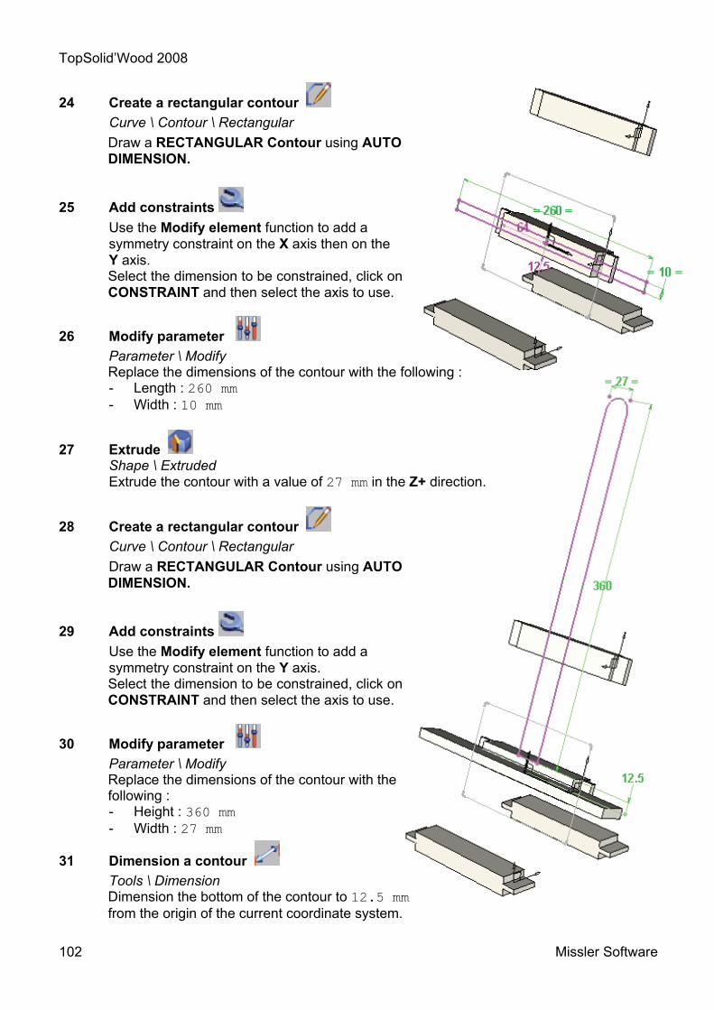
TopSolid’Wood 2008
102 Missler Software
24 Create a rectangular contour Curve \ Contour \ Rectangular
Draw a RECTANGULAR Contour using AUTO DIMENSION.
25 Add constraints Use the Modify element function to add a symmetry constraint on the X axis then on the Y axis. Select the dimension to be constrained, click on CONSTRAINT and then select the axis to use.
26 Modify parameter Parameter \ Modify
Replace the dimensions of the contour with the following : - Length : 260 mm - Width : 10 mm
27 Extrude Shape \ Extruded
Extrude the contour with a value of 27 mm in the Z+ direction.
28 Create a rectangular contour Curve \ Contour \ Rectangular
Draw a RECTANGULAR Contour using AUTO DIMENSION.
29 Add constraints Use the Modify element function to add a symmetry constraint on the Y axis. Select the dimension to be constrained, click on CONSTRAINT and then select the axis to use.
30 Modify parameter Parameter \ Modify
Replace the dimensions of the contour with the following : - Height : 360 mm - Width : 27 mm
31 Dimension a contour Tools \ Dimension
Dimension the bottom of the contour to 12.5 mm from the origin of the current coordinate system.

TopSolid’Wood 2008
Missler Software 103
32 Fillet Curve \ Fillet
Create a fillet of 13.5 mm on the top of the contour.
33 Extrude Shape \ Extrude
Extrude the contour with a value of 12.5 mm in the Z- direction
34 Activate layer 4 Make layer 4 current
35 Extrude Shape \ Extrude
Extrude the contours present on layer 0 with a value of 27 mm in the X+ direction.
Assembly by tenon-mortice
36 Tenon-mortice assembly Wood \ Tenon-mortice assembly
Create the assembly by selecting the option FROM TENON OR MORTICE. Select one of the tenons in contact with an element, then the part to mortice.
By default, the function implements a selection filter that makes it possible to only select an edge belonging to a tenon.
Define the mortices with the following values :
- Play on sides : 0.25 mm - Play on bottom : 0 mm - Allowance on cheeks : 0.25 mm
Select OK.
Repeat the operation for the other tenons of the easel.
37 Fillet Shape \ Fillet
Create a fillet of 10 mm as shown opposite.
38 Repeat Edit \ Repeat
Using the selection lasso , select the last two parts extruded. Choose SIMPLE MIRROR as the repetition type, and then use the YZ plane.

TopSolid’Wood 2008
104 Missler Software

TopSolid’Wood 2008
Missler Software 105
Workshop : Creation of a trestle
In this workshop, you will learn to : • Use various geometry tools, • Create a thickened profile, • Use the various points and coordinate systems • To create a tenon/mortice assembly, • To repeat elements.

TopSolid’Wood 2008
106 Missler Software
A
Create the geometry of the trestle
1 Open a new design document Choose Without Template in the proposed list of New Document template models.
2 Create a rectangular contour Curve \ Contour \ Rectangular Draw a RECTANGULAR Contour using AUTO DIMENSION.
3 Add constraints Use the Modify element function to add a symmetry constraint on the X axis then on the Y axis. Select the dimension to be constrained, click on CONSTRAINT and then select the axis to use.
4 Create the parameters Parameter \ Create
Create the height and length parameters of the trestle: H=800, l=1000
5 Modify parameter Parameter \ Modify Replace the dimensions of the contour with the values shown (See above).
6 Create an offset point Tools \ Point \ Offset point
Create an offset point 80 mm in the Y- direction, starting from the upper left point. The point created corresponds to point A.
7 Create a rectangle Curve \ Rectangle
Using the DIAGONAL mode, draw a rectangle starting from point A and finishing at the upper right corner of the large rectangle.
8 Create a rectangular contour Curve \ Contour \ Rectangular
Draw a new RECTANGULAR Contour with AUTO DIMENSION below the coordinate system.

TopSolid’Wood 2008
Missler Software 107
9 Add constraints Use the Modify element function to add a symmetry constraint on the Y axis. Select the dimension to be constrained, click on CONSTRAINT and then select the axis to use.
10 Dimension a contour Tools \ Dimension
Dimension the top of the previously created rectangle to 165 mm from the bottom.
11 Modify parameter Parameter \ Modify Replace the contour dimensions with the values opposite (See above).
- Length : l-245 mm - Height : 35 mm
12 Create an offset point Tools \ Point \ Offset point
Create an offset point 10 mm in the Y+ direction, starting from the upper left point of the previously created contour.
13 Create a rectangular contour Curve \ Contour \ Rectangular
Draw a new RECTANGULAR Contour with AUTO DIMENSION.

TopSolid’Wood 2008
108 Missler Software
B
Created point
14 Modify parameter Parameter \ Modify Replace the dimensions of the rectangular contour with the following values :
- Width : 35 mm - Height : 55 mm
15 Create an offset point Tools \ Point \ Offset point
Create an offset point 10 mm in the X+ direction, starting from the upper left point of the previously created contour. The point created corresponds to the point B.
16 Create a centre point Tools \ Point \ Centre key point
Create a centre point on the lower segment of the upper rectangle as shown below.
17 Create an offset point Tools \ Point \ Offset point
Create an offset point 50 mm in the X- direction, starting from the centre point created previously. The point created corresponds to point C.
18 Create a line Curve \ Line
Draw a line starting on point B and ending on point C.

TopSolid’Wood 2008
Missler Software 109
D
E
19 Create offset curves Curve \ Offset curve
Create an offset curve, offset by 55 mm from the previously created line. (See the diagram below).
20 Create a projected point Tools \ Point \ Projected point
Create a projected point E, in the Y- direction to the offset curve previously created. Use point D as the reference point.
21 Create a contour Curve \ Contour
Draw a closed contour as shown opposite while passing through the points D and E created previously. (Contour surrounding the hatched zone)

TopSolid’Wood 2008
110 Missler Software
Representation of a parallel constraint
22 Activate layer 1 Make layer 1 current.
23 Create a coordinate system Tools \ Coordinate system \ Coordinate system 2 axes
Select THROUGH POINT. Click on the lower left corner of the enclosing rectangle, then click on Z+. Use Y+ as the Y axis.
Make the created coordinate system current.
24 Create an offset point Tools \ Point \ Offset point
Create an offset point 250 mm in the X- direction, starting from the origin of the current coordinate system.
25 Create a contour Curve \ Contour
Draw a closed contour as shown opposite. Use the previously created point as the starting point of the contour.
26 Add a constraint Tools \ Constraint Add a parallel constraint between two elements. Choose PARALLEL, from the drop-down list. Select the profiles as shown opposite. A parallel constraint appears.
//
Profile 1
Profile 2

TopSolid’Wood 2008
Missler Software 111
27 Dimension a contour Tools \ Dimension
Dimension the contour as shown opposite. 28 Activate layer 2 Make layer 2 current.
Model the trestle
29 Extrude Shape \ Extruded
Extrude the contour a value of 70 mm in the Z- direction with an offset distance of 70 mm.
30 Repeat Edit \ Repeat
Make the ABSOLUTE COORDINATE SYSTEM current. Select the foot, then choose SIMPLE MIRROR as the repetition type from the list. Use the XY plane.
31 Activate layer 3 Make layer 3 current.

TopSolid’Wood 2008
112 Missler Software
Interior face of the front foot Interior face of the back foot
Result
32 Extrude Shape \ Extruded
Extrude the following contours using the CENTERED mode with the extrusion values shown :
33 Extrude Shape \ Extrude
Extrude the last contour using the CENTERED mode. Use the TO mode and use the following faces :
48 mm
20 mm
55 mm

TopSolid’Wood 2008
Missler Software 113
Support face Direction of tenon Left face Bottom face
Result
34 Turn off layers Turn off layers 0, 1 and 2
Tenon the lower cross-piece
35 Tenon Wood \ Tenon
Create a horizontal tenon on the lower cross-piece. Selection the MANUAL mode for the direction of the tenon, and select the support face of the tenon. Click on an edge to define the direction of the tenon. Click on the red arrow if the direction is to be changed. Select the left face, then the bottom face of the tenon. Select the simple tenon from the USER MODELS list. Define the characteristics of the tenon by entering the following information :
- Width setting : Total width - Thickness setting : e centered - Value of L : 50 mm - Value of e : 15 mm
Select OK.

TopSolid’Wood 2008
114 Missler Software
Trimming Plane Direction
Use the option PROPAGATION ON OPPOSITE FACE to obtain the same operation on the other face of the part.
36 Activate layer 2 Make layer 2 current
Assembly by tenon-mortice
37 Tenon-mortice assembly Wood \ Tenon-mortice assembly
Create the assembly by selecting the option FROM TENON OR MORTICE. Select one of the tenons in contact with an element, then the part to mortice.
By default, the function implements a selection filter that makes it possible to only select an edge belonging to a tenon.
Define the mortices with the following values :
- Play on sides : 0.25 mm - Play on bottom : 0 mm - Allowance on cheeks : 0.25 mm
Select OK. Repeat the procedure to create another tenon/mortice assembly using the other tenon.
38 Trim a part by a plane Shape \ Trim Choose from the list the BY PLANE mode, then click on the lower cross-piece.
Use the front face of the foot as the Trimming Plane. The direction of the red arrow corresponds to the side which the material will be removed from. This must point towards the outside of the part.
Select OK to confirm.
To view the result, turn off layer 3.

TopSolid’Wood 2008
Missler Software 115
Ensure Hide tools = NO is selected and then select OK. Follow the same procedure to trim the length of the second tenon. Use the same options as above.
39 Repeat Edit \ Repeat
Select the feet. Choose SIMPLE MIRROR as the repetition type, and then use the YZ plane. Now select the cross-piece for the supports, then the bottom cross-piece in order to obtain the result shown below.
Trimming plane Direction

TopSolid’Wood 2008
116 Missler Software

TopSolid’Wood 2008
Missler Software 117
Workshop : Creation of a door
On this workshop you will learn to : • Model the parametric elements, • Place a profile, • Make a profile / counter-profile assembly.

TopSolid’Wood 2008
118 Missler Software
Create the geometry for the door
1 Open a new document Choose Without Template in the proposed list of New Document template models.
2 Create a rectangular contour Curve \ Contour \ Rectangular
Design a Contour RECTANGULAR in AUTO DIMENSION.
3 Add the constraints Use the function Modify element to add a symmetry constraint on the X axis then on the Y axis.
4 Create the parameters Parameter \ Create
Create the length and width parameters for the door: H=600, la=450
5 Modify parameter Parameter \ Modify
Change the contour’s dimension for those of their parameters (See below). 6 Create 4 rectangular contours
Using the function RECTANGULR CONTOUR , trace 4 rectangular contours anchored to the 4 corners of the previously constructed rectangle, then make the auto dimension of each entity.
7 Dimension the 4 rectangular contours Change the dimensions for the corresponding H and la parameters. Create an s parameter with a value of 80mm and apply it on the width of the 4 rectangles.

TopSolid’Wood 2008
Missler Software 119
8 Activate layer 1 Make current layer 1
9 Extrude the jambs and transoms Shape \ Extruded Create an extruded shape pm the Z+ axis with a value
of 22 mm from each rectangular contour.
10 Verify and save Modify the values of the H and la parameters to validate the construction.
Profiling the jambs and transoms
11 Internal molding Wood \ Molding Make the molding on the upper transom by selecting
- the reference face (upper face of the shape) - the path of the tool (the longest edge of the shape)
Select the Profilage et contre profilage/Type 9 tool.
Select OK.
Use the option COPY MOULDING to make the same machining on the other 3 parts. Select the face and the tool path for each part.
Reference face
Tool’s path
The arrow represents the position of the tool’s axis, so it must be oriented towards the outside of the part

TopSolid’Wood 2008
120 Missler Software
COPY MOULDING will merge the type of molding applied on the jambs and transoms.
12 External molding Wood \ Molding Make the external molding of the door with the option
Apply it to one of the parts of the frame by selecting:
- the reference face (upper face of the shape) - the path of the tool *
* In this case the path tool is made by the successive selection of the 4 edges corresponding to the lengths of the 4 parts (the tool path will appear as a red and white rectangle on the screen).
Select a Profilage/Type 1.tool Click OK.
Counter molding of the transoms
13 Counter molding Wood / Counter molding Make the counter molding on the upper transom of the frame by selecting:
- the shape to modify >> the transom to counter molding - the reference molding >> an edge on the internal molding of the jamb

TopSolid’Wood 2008
Missler Software 121
Model the panel 14 Activate layer 3 Make current layer 3
15 Create a rectangular contour Design a Contour RECTANGULAR in AUTO DIMENSION centered on the absolute coordinate system.
16 Extrude the panel Shape \ Extruded
Extrude the contour with a value of 15mm following Z+ with an offset value of 4mm with the help of the option in order to match the panel to the slot.
17 Create a parameter Parameter \ Create Create a parameter r with a value of 17mm
18 Modify parameter Parameter \ Modify
Change the parameters of the panel to the following values:
- the -2*s+2*r for the width, - H -2*s+2*r for the height.
In order to make the following operation easier, deactivate the layers 1 and 2 to hide the jambs and transoms.
Profiling the panel
19 Molding of the flat band Wood \ Molding
Execute the molding on the central panel by selecting:
- the reference face (upper face of the shape) - the tool path (rectangular contour or the edges of the upper face).
4

TopSolid’Wood 2008
122 Missler Software
Select the Flat band/Type 1 tool
Click OK
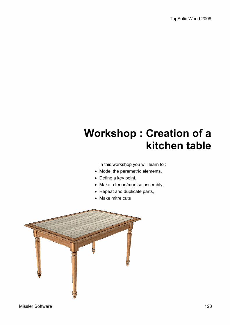
TopSolid’Wood 2008
Missler Software 123
Workshop : Creation of a kitchen table
In this workshop you will learn to : • Model the parametric elements, • Define a key point, • Make a tenon/mortise assembly, • Repeat and duplicate parts, • Make mitre cuts

TopSolid’Wood 2008
124 Missler Software
Create the table’s legs
1 Open a design document File \ Open
Open the Pied file available at this address : ftp.topsolid.com/public/TopSolidWood/Support TopSolid’Wood 2008.
2 Extrude the leg Shape \ Extruded
Create an extruded shape in CENTERED mode with a value of 65 mm from the rectangular profile.
3 Turning Wood \ Turning
Select the part to machine, then the profile. Use the length’s axis as the turning axis. Confirm the direction.
Select OK.
4 Create a coordinate system Tools \ Coordinate system \ Coordinate system 2 axis Create a coordinate system following 2 axis.
Select the passing point, the X direction then the Y direction.
Passing point X+ direction
Y+ direction Make current

TopSolid’Wood 2008
Missler Software 125
5 Define a key point Assembly \ Define component \ Define key points
Click on the previous coordinate system, name it as fr1 and define it as leg coordinate system.
6 Leg’s definition Wood \ Define part
Define the part giving:
- A designation: Leg - A material: Oak
7 Save File \ Save Save the filer
Create the transoms
8 Open a new document Select New design document from the proposed list Without a template.
9 Create a rectangular contour Curve \ Contour \ Rectangular Draw a RECTANGULAR CONTOUR in AUTO DIMENSION. 10 Add the constraints
Use the function Modify element to add a symmetry constraint on the X axis en then on the Y axis.
11 Create the parameters Parameter \ Crate
Create the table’s length and width parameters: L=800, la=550
12 Modify parameter Parameter \ Modify
Substitute the dimensions of the contour by their parameters (See above).

TopSolid’Wood 2008
126 Missler Software
13 Create 2 rectangular contours Curve \ Contour \ Rectangular
Design 2 rectangular contours as the table’s transoms. Each one of these must be constrained on the length and have an offset of 20 mm.
Values for the transoms: L-130 mm for the length la-130 mm for the width 22 mm for the thickness
14 Extrude the transoms Shape \ Extruded Extrude each part with a value of 120 mm in the Z- direction .
Import the leg 15 Activate layer 1 Make current layer 1
16 Create a coordinate system Tools \ Coordinate system \ Coordinate system on point Create a coordinate system on the upper left corner of the rectangle.
Make it current

TopSolid’Wood 2008
Missler Software 127
17 Inset the leg Assembly \ Include sub assembly - part Insert the leg on the current coordinate system.
Click STOP.
Repeat the leg and the transoms
18 Make a coordinate system current Make current the ABSOLUTE coordinate system
19 Repeat the transoms Edit \ Repeat Select the part to repeat and choose the repetition type SIMPLE MIRROR:
- for the length’s transom use the plane XZ. for the width’s transom use the plane YZ.
20 Repeat the leg Edit \ Repeat
Select the leg and choose the repetition type DOUBLE MIRROR with the planes XZ and YZ.

TopSolid’Wood 2008
128 Missler Software
Support face Start face Term face
Pin assembly
21 Pin assembly Wood \ Other processes \ Pin assembly
Select the component 30 x 8 Smooth pin available in the standard TOPWOOD/Assemblies/Pins.
Define the position of the assembly by selecting:
- The support face for the hardware* - Hatched Zone - - The start face or edge - 1 - - Select CENTERED AUTOMATICALLY - The term face or edge - 2 -
* a filter allows the user to only select faces in contact with other faces.
Select the support face, which is the edge of the transom in contact with the foot. Select the upper face of the transom as the start face. Click on CENTERED AUTOMATICALLY, then select the bottom face of the transom.
1
2Face support

TopSolid’Wood 2008
Missler Software 129
Fill in the distribution mode with the following information :
Distribution mode: Step centered Step : 64 mm Check Optimize the number of elements. Select OK.
Use the COPY PROPAGATION to obtain the same distribution on the other assemblies.
Create the table top 22 Activate layer 2 Make current layer 2
23 Create a parallel profile Curve \ Parallel Make a parallel to the initial rectangle of 80 mm.
24 Create 2 rectangular contours Curve \ Contour \ Rectangular
Design 2 rectangular contours corresponding to the sides of the table top.

TopSolid’Wood 2008
130 Missler Software
25 Modify parameter Parameter \ Modify
Change the dimensions of the contours by its corresponding parameters (See below).
Value for the table top sides: L+160 mm on the table length La+160 mm on the table width 70 mm for the side’s width
26 Create a rectangular contour Curve \ Contour \ Rectangular Draw a RECTANGULAR CONTOUR in AUTO DIMENSION. 27 Add the constraints
Use the Modify element function to add symmetry constrain on the X axis then on the Y axis.
28 Modify parameter Parameter \ Modify
Select the dimension to modify, then take the option REPLACE and enter the corresponding parameter:
- L+20 mm for the length - la+20 mm for the width -
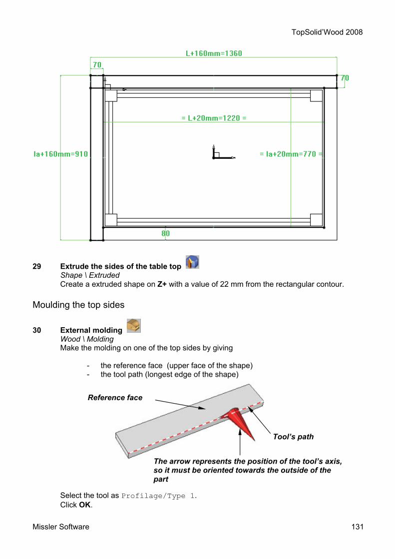
TopSolid’Wood 2008
Missler Software 131
29 Extrude the sides of the table top Shape \ Extruded Create a extruded shape on Z+ with a value of 22 mm from the rectangular contour.
Moulding the top sides
30 External molding Wood \ Molding Make the molding on one of the top sides by giving
- the reference face (upper face of the shape) - the tool path (longest edge of the shape)
Select the tool as Profilage/Type 1.
Click OK.
Reference face
Tool’s path
The arrow represents the position of the tool’s axis, so it must be oriented towards the outside of the part

TopSolid’Wood 2008
132 Missler Software
Use the option COPY MOULDING to make the same molding on the second table top side.

TopSolid’Wood 2008
Missler Software 133
Duplicate the table top sides
31 Duplicate the table top sides Edit \ Duplicate Select the MIRROR type of repetition:
- for the length’s sides use the plane XZ. - for the width’s sides use the plane YZ
Choose the option EXISTING OPERATIONS and select the parts to duplicate.
Cutting the sides’ corners
32 Miter cut Wood \ Cutext miter Make a miter union on the sides. Specify:
- the form to modify and the direction* - the tool and the tool’s path
* the requested directions (here with the red arrows) are to determine the bisector where the parts are going to be sawn
Repeat the operation con the rest of the corners.
Shape to modify
Tool to use

TopSolid’Wood 2008
134 Missler Software
The kitchen table is finished.

TopSolid’Wood 2008
Missler Software 135

TopSolid’Wood 2008
136 Missler Software
Workshop : Creation of a molding
In this workshop you will learn to : • Build a parametric contour, • Define the key points, • Save a standard, • Create a catalogue, • Insert a molding component, • Use the molding process.

TopSolid’Wood 2008
Missler Software 137
The creation of a molding implies to follow certain conditions described below. If one or more of the conditions are not respected the created tool will not work at all.
Creation of a molding
Create the molding geometry
1 Open a new document Select from the list a New document Without template.
2 Create a coordinate system
Tools \ Coordinate system Create a XY coordinate system and make it current.
3 Create a contour Curve \ Contour Create the contour corresponding to the section of the molding with its dimensional parameters.
4 Create a duplicate coordinate system Tools \ Coordinate system \ Duplicated coordinate system Create a coordinate system from the current one and duplicate it by a translation following Z+ with a value h=100mm.

TopSolid’Wood 2008
138 Missler Software
5 Create a line Curve \ Line Create a line between the two coordinate systems
6 Extrude the profile Shape \ Extruded
Extrude the section of the profile with an option of direction. Select the line (arrow pointing up) then click on the duplicate coordinate system in order to define the height of the part.
Definition of the part
7 Definition of the part Wood \ Define part
Define the element.
Declare the elements. 8 Name the elements Edit \ Name
The name for the origins is imposed: - lower origin: fr1 - upper origin: fr2.
fr1
fr2

TopSolid’Wood 2008
Missler Software 139
9 Define a driver Assembly \ Define component \ Define drivers
Define the parameter h as a driver.
10 Define a key point Assembly \ Define component \ Define key points
Create the points that will serve to insert and position the component, or recover the points that have served to create the section. Name each key point as follows :
- name of key point: P1 - designation of key point: Centre
The points must be attached to the plane of the grille of the coordinate system
fr1.
P2 – Upper left angle P4 - Upper right angle
P5 – Lower right angle P3 - Lower left angle
P1 - Centre

TopSolid’Wood 2008
140 Missler Software
Save the template 11 Save the template
Assembly \ Define component \ Edit \ Save template Select SAVE STANDARD TEMPLATE
Save it in MY STANDARD 3D \ Profilés \ Molding \ Type 1.
If the profile has several sizes or settings it will be possible to define a catalogue.
12 Define the extruded component Assembly \ Defined component \ Define extruded component
It will be possible to automatically make miter and plane cuts. Run the function and select the extruded part. The program is going to create the necessary files for the processes y the document contains all the necessary elements for the creation of an extruded component.
13 Save File / Save
Save the file.
Define a catalogue
14 Create a catalogue Assembly \ Define component \ Edit catalogue header
When using the function and selecting All parameters and texts except drives, a Excel table will open. Enter the values for the parameters following the different codes. Save the Excel file

TopSolid’Wood 2008
Missler Software 141
Insertion of the molding
15 Open a new document Select from the list a New document Without template
16 Create a regular polygon profile Curve \ Other curves \ Regular polygon Create a regular polygon of 5 sides with a diameter of 500 mm.
17 Insert a standard component Assembly \ Include standard Select the component profilé available on the standard MY STANDARD 3D /Molding / Type 1. Select the 1st passing point then the second one.
In order to position the profile it will be possible to choose one of the key points previously created.
1
2
Key point P1 - Center Key point P2 – Upper left angle
Key point P3 – Lower left angle

TopSolid’Wood 2008
142 Missler Software
Do the same on all the points
The direction of the extruded profile depends of the order of selection of the passing points.
17 Use the process Assembly \ Use process Select one part to activate the processes of the molding. (1). Select MITER CUT, then click the second part that will have the cut (2). Click OK.
Repeat the same procedure to make the cuts on the other parts.
Key point P4 – Upper right angle
Key point P5 – Lower right angle
12

TopSolid’Wood 2008
Missler Software 143
Workshop - Creation of a wooden bicycle
In this workshop, you will learn to : • Model simple parts • Create an assembly using constrained
positioning

TopSolid’Wood 2008
144 Missler Software
Create the frame
1 Open a new design document Choose Without Template in the proposed list of New Document template models.
2 Create a contour Curve \ Contour Draw the Contour shown below.
3 Dimension the contour Tools \ Dimension
Dimension the contour as shown below.
4 Add constraints Use the Modify element function to add a symmetry constraint on the X axis then on the Y axis.
5 Modify parameter Parameter \ Modify
Replace the dimensions of the contour with the values shown (See above).
6 Fillet Curve \ Fillet
Use the GLOBAL mode and create a 5 mm fillet on the contour.
7 Extrude Shape \ Extruded
Extrude the contour a value of 70 mm in the Z- direction
8 Fillet Shape \ Fillet
Create 5 mm fillets on the edges of the extruded shape.

TopSolid’Wood 2008
Missler Software 145
A 1
2
4
3
9 Activate layer 1 Make layer 1 current.
10 Create a rectangular contour Curve \ Contour \ Rectangular Draw a RECTANGULAR Contour using AUTO DIMENSION.
11 Add constraints Use the Modify element function to add a symmetry constraint on the X axis.
12 Position the contour Tools \ Dimension
Position the rectangular contour 25 mm from the origin of the coordinate system in the X- direction.
13 Modify parameter Parameter \ Modify
Replace the dimensions of the contour with the values shown (See above).
14 Create offset points Tools \ Point \ Offset point
Create the following offset points :
- Point 1 is positioned 60 mm from point A in the X- direction.
- Point 2 is positioned 40 mm from point A in the Y- direction
15 Create duplicate points Tools \ Point \ Duplicate point
Create the duplicate points 3 and 4 using AXIS SYMMETRY, the X axis and the points 1 and 2.

TopSolid’Wood 2008
146 Missler Software
5
A 1
2
4
3
16 Create a centre point Tools \ Point \ Center key point
Create the centre point, 5, on the rectangular contour.
17 Create the circular arcs Curve \ Circle
Create a circular arc of Ø130 mm using the Passing point mode and the points 1 and 2, then a second arc using the points 3 and 4.
Create a third arc using the points 1,5 and 4, again using the Passing point mode.
18 Create a traced contour Curve \ Contour Trace the Contour shown opposite.
19 Fillet Curve \ Fillet
Use the GLOBAL mode and create a fillet of 5 mm on the contour.
20 Extrude Shape \ Extruded
Extrude the contour with a value of 30 mm in the Z+ direction.
21 Fillet Shape \ Fillet
Create 5 mm fillets on the edges of the extruded shape. 22 Activate layer 2 Make layer 2 current.

TopSolid’Wood 2008
Missler Software 147
23 Create a rectangular contour Curve \ Contour \ Rectangular Draw a RECTANGULAR Contour using AUTO DIMENSION.
24 Add constraints Use the Modify element function to add a symmetry constraint on the X axis then on the Y axis.
25 Modify parameter Parameter \ Modify
Replace the dimensions of the contour with the values shown (See above).
26 Fillet Curve \ Fillet
Use the GLOBAL mode and create a fillet of 5 mm on the rectangular contour.
27 Extrude Shape \ Extruded
Extrude the contour a value of 40 mm in the Z- direction with an offset distance of 120 mm.
28 Fillet Shape \ Fillet
Create 5 mm fillets on the edges of the extruded shape.
29 Activate layer 3 Make layer 3 current.

TopSolid’Wood 2008
148 Missler Software
30 Create a rectangular contour Curve \ Contour \ Rectangular Draw a RECTANGULAR Contour using AUTO DIMENSION.
31 Add constraints Use the Modify element function to add a symmetry constraint on the X axis.
32 Position the contour Tools \ Dimension
Position the rectangular contour 165 mm from the origin of the coordinate system in the X- direction.
33 Modify parameter Parameter \ Modify
Replace the dimensions of the contour with the values shown (See above).
34 Fillet Curve \ Fillet
Use the GLOBAL mode and create a fillet of 5 mm on the contour.
35 Extrude the separation panel Shape \ Extruded
Extrude the contour in the Z- direction with an offset distance of 25 mm. Use the mode TO, and then click on the top face of the lower part as shown below.
Result Face

TopSolid’Wood 2008
Missler Software 149
36 Repeat Edit \ Repeat
Select the part created in the previous step and then using the SUM OF PROPAGATIONS repetition type, enter the following characteristics :
- Propagation number 1 : LINEAR in the X+ direction, Total distance of 60 mm, Total number of 2.
- Propagation number 2 : LINEAR in the X+ direction,
Total distance of 285 mm, Total number of 2.
Click on STOP.
37 Drill Shape \ Drilling
Create a boring hole of Ø25 mm on the lower cross-piece of the frame. Centre the hole on the width of the part, and 60 mm from the front face. Create an identical drilling on the upper cross-piece. Use the COORDINATE SYSTEM mode, and select the coordinate system from the previously created hole.
38 Activate layer 4 Make layer 4 current.
39 Create a Cartesian point Tools \ Point \ Cartesian point
Create a Cartesian point starting from the ABSOLUTE COORDINATE SYSTEM. The coordinates for the point are as follows :
X coordinate : -190 - Y coordinate : 0 - Z coordinate : -180
40 Create a coordinate system Tools \ Coordinate system Create a coordinate system on 2 axes.
The THROUGH POINT is the point created in the previous step. Select the X+ for the X direction. Select Z+ for the Y direction.
Make the created coordinate system the current coordinate system.
Upper cross-piece
Lower cross-piece
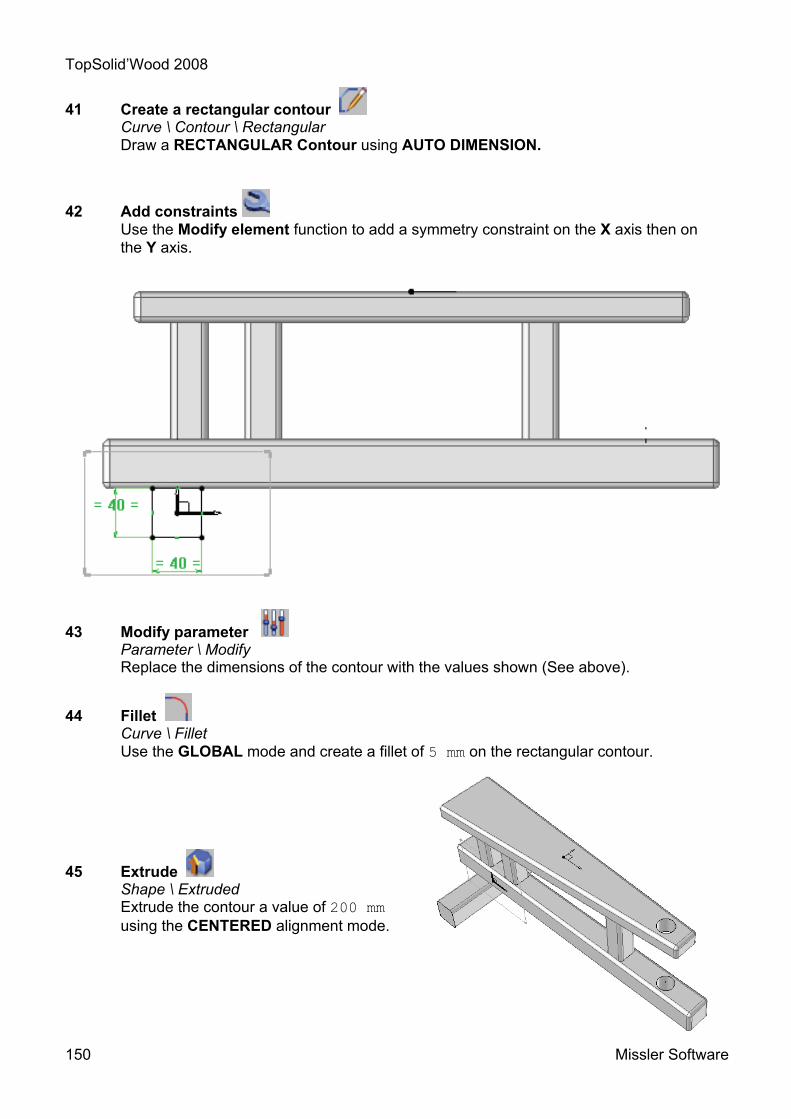
TopSolid’Wood 2008
150 Missler Software
41 Create a rectangular contour Curve \ Contour \ Rectangular Draw a RECTANGULAR Contour using AUTO DIMENSION.
42 Add constraints Use the Modify element function to add a symmetry constraint on the X axis then on the Y axis.
43 Modify parameter Parameter \ Modify
Replace the dimensions of the contour with the values shown (See above).
44 Fillet Curve \ Fillet
Use the GLOBAL mode and create a fillet of 5 mm on the rectangular contour.
45 Extrude Shape \ Extruded
Extrude the contour a value of 200 mm using the CENTERED alignment mode.
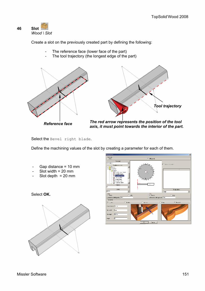
TopSolid’Wood 2008
Missler Software 151
46 Slot Wood \ Slot Create a slot on the previously created part by defining the following:
- The reference face (lower face of the part) - The tool trajectory (the longest edge of the part)
Select the Bevel right blade.
Define the machining values of the slot by creating a parameter for each of them.
- Gap distance = 10 mm - Slot width = 20 mm - Slot depth = 20 mm
Select OK.
Reference face
Tool trajectory
The red arrow represents the position of the tool axis, it must point towards the interior of the part.

TopSolid’Wood 2008
152 Missler Software
47 Activate layer 5 Make layer 5 current.
48 Create circles Curve \ Circle
Draw 3 circles of Ø20 mm, Ø30 mm, Ø140mm. The centers of these should be 10 mm from the coordinate system in the Y- direction.
49 Extrude Shape \ Extruded
Extrude the Ø20 mm circle a value of 200 mm using the CENTERED alignment mode.
Select the Ø30 mm and Ø140 mm circles. Extrude these circles a value of 60 mm in the Z+ direction with an offset distance of 105 mm.
50 Fillet Shape \ Fillet
Create a fillet of 5 mm on the faces of the wheel.
51 Repeat the wheels Edit \ Repeat
Select the wheel, then choose SIMPLE MIRROR as the repetition type from the list. Use the XY plane as the symmetry plane.
52 Definition of the part Wood \ Define part
Define the parts by entering :
- A designation : - A material - A type
53 Save File \ Save as Save the file as Frame.top

TopSolid’Wood 2008
Missler Software 153
Create the handlebars
1 Open a new design document Choose Without Template in the proposed list of New Document template models.
2 Create a rectangular contour Curve \ Contour \ Rectangular Draw a RECTANGULAR Contour using AUTO DIMENSION.
3 Add constraints Use the Modify element function to add a symmetry constraint on the X axis then on the Y axis.
4 Modify parameter Parameter \ Modify
Replace the dimensions of the contour with the values shown (See opposite).
5 Fillet Curve \ Fillet
Use the GLOBAL mode and create a 5 mm fillet on the rectangular contour.
6 Extrude Shape \ Extruded
Extrude the contour a value of 200 mm using the CENTERED alignment mode.
7 Slot Wood \ Slot Create a slot on the previously created part by defining the following:
- The reference face (lower face of the part) - The tool trajectory (the longest edge of the part)

TopSolid’Wood 2008
154 Missler Software
Select the Bevel right blade.
Define the machining values of the slot by creating a parameter for each of them.
- Gap distance = 10 mm - Slot width = 20 mm - Slot depth = 20 mm
Select OK. 8 Activate layer 1 Make layer 1 current.
Reference face
Tool trajectory
The red arrow represents the position of the tool axis, it must point towards the interior of the part.

TopSolid’Wood 2008
Missler Software 155
9 Create circles Curve \ Circle
Draw 3 circles of Ø20 mm, Ø30 mm, Ø140mm. The centers of these should be 10 mm from the coordinate system in the Y- direction.
10 Extrude Shape \ Extruded
Extrude the Ø20 mm circle a value of 330 mm using the CENTERED alignment mode.
Select the Ø30 mm and Ø140 mm circles. Extrude these circles a value of 60 mm in the Z+ direction with an offset distance of 105 mm.
11 Fillet Shape \ Fillet
Create a fillet of 5 mm on the faces of the wheel.
12 Repeat the wheels Edit \ Repeat
Select the wheel, then choose SIMPLE MIRROR as the repetition type from the list. Use the XY plane as the symmetry plane.
13 Drill Shape \ Drilling
Create a boring hole of Ø25 mm, 5 mm deep on the cross-piece. The hole should be centered on the width and length of the cross-piece.
14 Activate layer 2 Make layer 2 current.

TopSolid’Wood 2008
156 Missler Software
3
A
14
B 2
15 Create a duplicate coordinate system Tools \ Coordinate system
Create a duplicated coordinate system 310 mm in the Y+ direction from the ABSOLUTE COORDINATE SYSTEM.
Make the created coordinate system current.
16 Add constraints Use the Modify element function to position the coordinate system as shown opposite.
17 Create a rectangular contour Curve \ Contour \ Rectangular
Draw a RECTANGULAR Contour using AUTO DIMENSION.
18 Add constraints Use the Modify element function to add a symmetry constraint on the Y axis.
19 Position the contour Tools \ Dimension
Position the rectangular contour 30 mm from the origin of the absolute coordinate system in the Y+ direction.
20 Modify parameter Parameter \ Modify
Replace the dimensions of the contour with the values shown (See above).
21 Create duplicate points Tools \ Point \ Duplicate point
Create the following duplicate points :
- Point 1 is positioned 25 mm from point A in the Y- direction
- Point 2 is positioned 20 mm from point B in the X- direction
- Points 3 and 4 from points 1 and 2 using a simple mirror of the Y axis.
Y+ X+

TopSolid’Wood 2008
Missler Software 157
22 Create lines Curve \ Line
Create 2 lines. The first will be from point 1 to point 2 and the second from point 3 to point 4.
23 Create a circle Curve \ Circle
Create a circular arc using the Passing point mode. Click on the two lines created previously and the bottom of the rectangle to create a tangent arc.
Create a second arc again using the Passing point mode, and select points 1 and 4 and the top of the rectangle as shown above.
24 Create a contour Curve \ Contour
Trace the Contour shown opposite.
25 Extrude Shape \ Extruded
Extrude the contour with a value of 30 mm in the Z+ direction.
26 Drill Shape \ Drilling
Using the NON DYNAMIC, drill a Ø20 mm hole 25 mm deep hole on the part. Follow the diagrams below to define the positioning :
Arc 1
Arc 2
Face to drill First alignment face or edge
Parallel face or edge
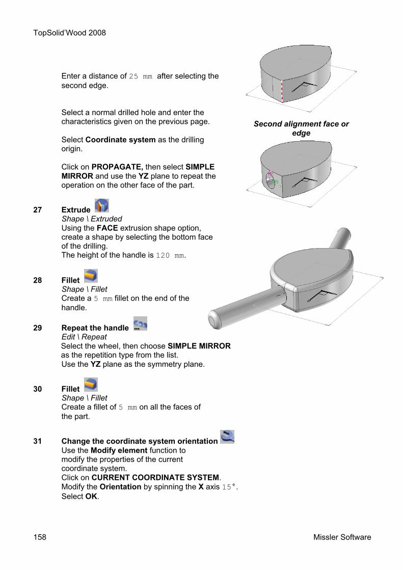
TopSolid’Wood 2008
158 Missler Software
Enter a distance of 25 mm after selecting the second edge.
Select a normal drilled hole and enter the characteristics given on the previous page. Select Coordinate system as the drilling origin.
Click on PROPAGATE, then select SIMPLE MIRROR and use the YZ plane to repeat the operation on the other face of the part.
27 Extrude Shape \ Extruded
Using the FACE extrusion shape option, create a shape by selecting the bottom face of the drilling. The height of the handle is 120 mm.
28 Fillet Shape \ Fillet
Create a 5 mm fillet on the end of the handle.
29 Repeat the handle Edit \ Repeat
Select the wheel, then choose SIMPLE MIRROR as the repetition type from the list. Use the YZ plane as the symmetry plane.
30 Fillet Shape \ Fillet
Create a fillet of 5 mm on all the faces of the part.
31 Change the coordinate system orientation Use the Modify element function to modify the properties of the current coordinate system. Click on CURRENT COORDINATE SYSTEM. Modify the Orientation by spinning the X axis 15°. Select OK.
Second alignment face or edge

TopSolid’Wood 2008
Missler Software 159
32 Change the current coordinate system Make the drilling axis of the Ø25 mm, 5 mm deep drilling on the cross-piece the current coordinate system as shown below.
33 Drill Shape \ Drilling
Using the COORDINATE SYSTEM mode, drill a Ø25 mm, 5 mm deep hole on the lower face of the handlebar.
In the hole dialogue box ensure that the Drilling origin is set to the Face mode.
34 Activate layer 3 Make layer 3 current.
Current coordinate system
Definition coordinate system
Reference face

TopSolid’Wood 2008
160 Missler Software
35 Extrude Shape \ Extruded
Using the FACE extrusion shape option, create a shape by selecting the bottom face of the drilled hole on the lower cross-piece. Use the mode, TO, and click on the bottom face of the drilled hole on the bottom of the handlebar.
36 Definition of the parts Wood \ Define part
Define the parts by entering :
- A designation - A material - A type
37 Save File \ Save as Save the file as Handlebar.top
Initial face
Trimming face
Result
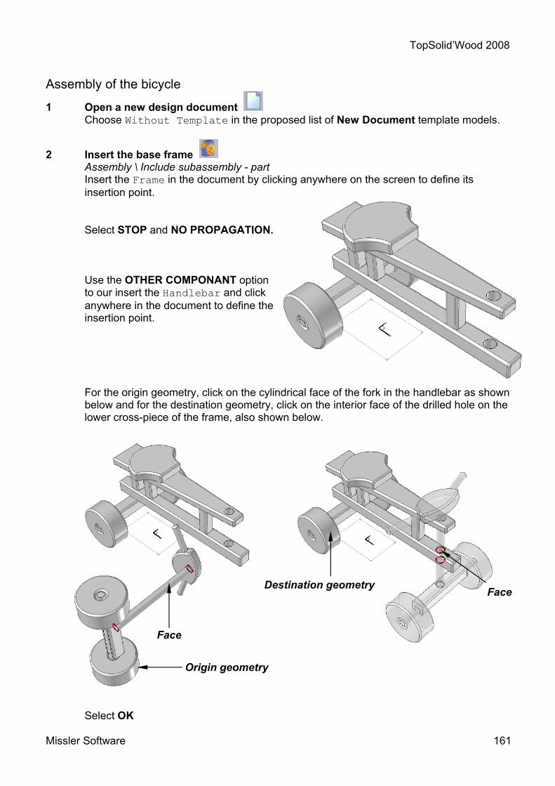
TopSolid’Wood 2008
Missler Software 161
Assembly of the bicycle
1 Open a new design document Choose Without Template in the proposed list of New Document template models.
2 Insert the base frame Assembly \ Include subassembly - part
Insert the Frame in the document by clicking anywhere on the screen to define its insertion point.
Select STOP and NO PROPAGATION.
Use the OTHER COMPONANT option to our insert the Handlebar and click anywhere in the document to define the insertion point.
For the origin geometry, click on the cylindrical face of the fork in the handlebar as shown below and for the destination geometry, click on the interior face of the drilled hole on the lower cross-piece of the frame, also shown below.
Select OK
Face
Face
Origin geometry
Destination geometry

TopSolid’Wood 2008
162 Missler Software
For the next origin geometry click on the upper face of the handlebar cross-piece as shown, and for the destination geometry click on the upper face of the lower cross-piece of the frame.
Select OK, STOP and NO PROPAGATION.
7 Move the assembly Edit \ Move parents
Select one of the two units that make up the assembly. You can now move one of the parts by simply moving your mouse.
8 Save File \ Save as
Face
Origin geometry
Face
Destination geometry

TopSolid’Wood 2008
Missler Software 163
Save the file as Wooden bicycle.top