Embed Size (px)
Citation preview

TONI HAKALA
CALCULATION TOOL FOR FAN COIL UNIT
Master of Science Thesis
Examiner: Professor Hannu Ahlstedt
Examiner and topic approved by the
Faculty Council of the Faculty of
Automation, Mechanical and Materials
Engineering on 9 May 2012.

II
ABSTRACT
TAMPERE UNIVERSITY OF TECHNOLOGY
Master’s Degree Programme in Automation Technology
HAKALA, TONI: Calculation tool for Fan Coil Unit
Master of Science Thesis, 47 pages, 8 appendix pages
February 2012
Major: Power Plant Engineering
Examiner: Professor Hannu Ahlstedt
Keywords: Fan Coil Unit, cooling, heating, sensible capacity, primary air, circulated air,
refrigerant
The aim of this Master of Science Thesis was to develop an MS Excel-based calculation
tool for cooling and heating capacities in Halton Group´s new product, the Fan Coil
Unit. The Fan Coil Unit is commonly used in passenger cabins of cruisers to cool or
heat the cabin air. The number of customer orders of the Fan Coil Unit has been
increasing, therefore, Halton Group’s subdivision Marine had a need to get this tool to
save time, which had earlier gone to calculations for each unit order separately.
The main components of Fan Coil Unit are a fan, a coil, a filter, a drip pan and an
electric heater. The operating principle of the Fan Coil Unit is that circulated cabin air
will be cooled in coil section by using water as refrigerant. After the coil, cooled
underinflated air goes through the fan section and gets slightly overpressured. Then the
air goes through the electric heater section, which is usually turned off in case of
cooling. After the electric heater, the circulated air duct is combined with a primary air
duct to form a chamber, wherein the circulated air from the cabin and pre-cooled
primary air are mixed. This mixture is called the supply air. Flow rate of primary air is
usually around 30 per cent of total airflow rate. Thereafter, supply air is blown into the
top of the cabin. Supply air temperature is usually 5-10 degrees lower than cabin
temperature.
Cooling demand consists of two kinds of heat loads: latent and sensible heat load.
The part of the heat load which is caused by evaporation, is called the latent heat load.
The latent heat load comes from for example the cabin, when the passenger's skin is
sweating and from the shower facilities when water vapor is released into the cabin air.
Sensible heat is heat exchanged by a body or thermodynamic system that has as its sole
effect a change of temperature.
This Thesis is divided into two parts. The first part will offer a basic theoretical
background for the features that will be dealt with in the second part. The basic
principles of Fan Coil Unit, heat transfer properties between air and water and other
mathematical functions that have been used in this work are presented in the first part.
The structure of the calculation tool and operations manual, are presented in the second
part.
As a result of this work, the calculation tool was developed and found to be
appropriate for designing as well as improving the Fan Coil Unit.
III
TIIVISTELMÄ
TAMPEREEN TEKNILLINEN YLIOPISTO
Automaatiotekniikan koulutusohjelma
HAKALA, TONI: Calculation tool for Fan Coil Unit
Diplomityö, 47 sivua, 8 liitesivua
Helmikuu 2012
Pääaine: Voimalaitostekniikka
Tarkastaja: Professori Hannu Ahlstedt
Avainsanat: Puhallinkonvektori, jäähdytys, lämmitys, tuntuva lämpökapasiteetti,
tuoreilma, kierrätysilma, jäähdytinaine
Tämän Diplomityön tarkoitus oli kehittää Microsoft Excel-pohjainen jäähdytys- ja
lämmityskapasiteettien laskentatyökalu Halton -konsernin uudelle tuotteelle,
puhallinkonvektorille (Fan Coil Unit). Puhallinkonvektoria käytetään risteilijöiden
matkustajahyteissä, olosuhteista riippuen joko jäähdyttämään tai lämmittämään hytti-
ilmaa. Työkalu tuli tarpeeseen, koska uuden tuotteen tilausmäärät ovat kasvaneet ja näin
ollen myös käsin laskemiseen kuluva aika on kasvanut niin suureksi, ettei se ole enää
ollut yritykselle kannattavaa.
Puhallinkonvektorin pääkomponentit ovat puhallin (fan), jäähdytyspatteri (coil),
suodatin (filter), tippakaukalo (drip pan) sekä sähkövastus (electric heater).
Puhallinkonvektorin idea jäähdytystapauksessa on, että hytti-ilma kulkeutuu laitteessa
olevan jäähdytyspatterin läpi, jossa jäähdyttävänä materiana kiertävä vesi vastaanottaa
lämpöenergiaa kiertoilmasta, saaden näin kiertoilman lämpötilan laskemaan. Tämän
jälkeen jäähdytetty kiertoilma kulkee puhaltimen ja lämmitysvastuksen läpi kammioon,
jossa siihen sekoittuu konvektorin erillisestä liitoksesta tuleva esijäähdytetty tuoreilma.
Yleensä tämän tuoreilman määrä on noin 30 prosenttia koko kierrätettävän ilman
määrästä. Lopuksi kiertoilman ja tuoreilman seos puhalletaan hytin yläosaan 5-10 °C
hyttilämpötilaa alemmassa lämpötilassa.
Jäähdytystarve koostuu kahdenlaisista lämpökuormista, latentista ja tuntuvasta
lämpökuormasta. Latenttilämmöllä tarkoitetaan höyrystymisen aiheuttamaa
lämpömäärää. Höyrystymistä tapahtuu muun muassa ihmisten iholla normaalin hikoilun
vaikutuksesta ja suihkutiloissa, joista vapautuu vesihöyryä hytti-ilman sekaan nostaen
näin hytti-ilman suhteellista kosteutta. Tuntuvalla lämmöllä vastaavasti tarkoitetaan
hytti-ilman ja jäähdytetyn ilman lämpötilaeroa, joten sen määrä voidaan mitata suoraan
lämpötilamittarilla.
Työ jakaantuu kahteen osaan. Kirjallisuusosassa selvitetään puhallinkonvektorin
toimintaa ja perusperiaatteita, ilman ja veden välisiä lämmönsiirto-ominaisuuksia, sekä
muita työhön liittyviä matemaattisia kaavoja. Työn tutkimusosassa käydään läpi
laskentatyökalun rakennetta, toimintaa ja käyttöohjetta.
Tämän työn tuloksena voidaan todeta laskentatyökalun olevan sille asetettuihin
tavoitteisiin soveltuva ja hyödyllinen puhallinkonvektorin kehittämisessä.
IV
PREFACE
This Master of Science Thesis has been carried out at the Halton Corporation in Lahti,
Finland. The supervisor and examiner of the thesis have been Professor Hannu Ahlstedt.
First of all, I would like to thank Professor Hannu Ahlstedt for providing me this
interesting topic and for his guidance. I also want to thank personnel in Halton Marine
and specially Jukka Maksimainen and Fabrice Deldreve for their help, because this
thesis would not have been possible to make without them.
My last gratitude goes to my family, to whom I am very grateful for the sacrifices
they have made in allowing me to study and for supporting and encouraging me in
every decision during this thesis work.
Thank you!
Tampere, February 2012
Toni Hakala

V
TABLE OF CONTENTS
1 INTRODUCTION ................................................................................................ 1
1.1 Fan Coil Unit ................................................................................................. 1
1.2 Calculation Tool ............................................................................................ 2
2 HALTON GROUP ................................................................................................ 3
2.1 Halton Marine ............................................................................................... 3
2.1.1 Halton Fan Coil Unit .......................................................................... 4
3 THEORY OF HEAT TRANSFER ........................................................................ 6
3.1 Properties of air and water vapour mixtures ................................................... 6
3.1.1 The general gas law ........................................................................... 6
3.1.2 Dalton's law of partial pressure .......................................................... 7
3.1.3 Saturation vapour pressure ................................................................. 7
3.1.4 Moisture content and relative humidity .............................................. 8
3.1.5 Dew point and specific volume of the mixture.................................... 8
3.1.6 Enthalpy of moist and dry air ............................................................. 9
3.2 The Psychrometry of Air Conditioning Processes ........................................ 10
3.2.1 Sensible heating and cooling ............................................................ 11
3.2.2 Dehumidification ............................................................................. 11
3.2.3 Cooling and dehumidification with reheat ........................................ 13
3.2.4 Pre-heat and humidification with reheat ........................................... 13
3.3 Comfort and Design Conditions ................................................................... 13
3.3.1 The choice of inside design conditions ............................................. 14
3.3.2 Design temperatures and heat gains .................................................. 14
3.3.3 Sensible heat removal ...................................................................... 15
3.3.4 The specific heat capacity of humid air ............................................ 15
3.3.5 Latent heat removal.......................................................................... 15
3.3.6 Heat gain arising from fan power ..................................................... 16
3.3.7 Other heat gains ............................................................................... 17
3.4 Air Cooler Coils .......................................................................................... 18
3.4.1 Parallel and counter flow.................................................................. 19
3.4.2 Contact factor .................................................................................. 21
3.4.3 Heat and mass transfer to cooler coils .............................................. 24
3.5 Fan performance and airflow in ducts .......................................................... 28
4 CALCULATION TOOL ..................................................................................... 32
4.1 General information..................................................................................... 32
4.1.1 Getting started.................................................................................. 32
4.1.2 Conditional formatting ..................................................................... 32
4.1.3 VBA -macros ................................................................................... 33
4.2 FCU -tab ..................................................................................................... 33
4.2.1 Mode selection and supply air state .................................................. 33
4.2.2 Capacities and air pressures ............................................................. 34

VI
4.2.3 Filter section and default settings ..................................................... 35
4.2.4 Primary and circulated air states ....................................................... 36
4.2.5 Listed faults ..................................................................................... 36
4.2.6 Electric heater and fan -sections ....................................................... 39
4.2.7 Water valve and coil section............................................................. 39
4.3 Fan -tab ....................................................................................................... 40
4.3.1 Adding and removing fans ............................................................... 40
4.4 Coil -tab ...................................................................................................... 41
4.4.1 Adding and removing coils .............................................................. 41
4.5 Prints -tab .................................................................................................... 42
4.5.1 Coil properties ................................................................................. 43
4.5.2 Fan Coil Unit specifications ............................................................. 44
4.6 Main -tab ..................................................................................................... 44
4.7 Charts -tab ................................................................................................... 44
5 CONCLUSIONS ................................................................................................. 45
REFERENCES ........................................................................................................... 46
APPENDIX A: Exploded view of Fan Coil Unit ......................................................... 48
APPENDIX B: Prints of the tool ................................................................................. 49
APPENDIX C: VBA-Macro codes.............................................................................. 52

VII
LIST OF ABBREVIATIONS AND TERMS
p Air pressure drop [Pa]
t Air temperature change [°C]
coil Contact factor of coil [-]
ε Effectiveness [-]
η Efficiency [-]
Fin parameter [-]
λ Thermal conductivity [W/(m×K)]
δf Fin thickness [m]
ρair Density of air [kg/m3]
ρwater Density of water [kg/m3]
Kinematic viscosity [m2/s]
v Volumetric flow rate [m3/s]
A Area [m2]
Af Face area of coil [m2]
Ar Total external surface area per tube row [m2]
At Total external surface area of the coil [m2]
C Heat capacity [J/K]
Cp Specific heat at constant pressure [J/(kg×K)]
Cr Critical heat capacity rate of fluids [-]
d Diameter [m]
g Moisture content [kgwater/kgair]
h Enthalpy [kJ/kg]
ha Heat transfer coefficient on the air side [W/(m2×K)]
hfg Latent heat of evaporation [kJ/kgwater]
hg Enthalpy of water vapour [kJ/kg]
LMTDas Logarithmic mean temperature difference between the air
stream and the mean coil surface temperature [°C]
LMTDaw Logarithmic mean temperature difference between the air
stream and the water flow [°C]
m Mass flow rate [kg/s]
mcond Condensed water [kgwater/kgair]
M Molecular mass [g/mol]
NTU Number of Transfer Units [-]
patm Barometric pressure [Pa]
ps Pressure of water vapour [Pa]
pss Saturation vapour pressure [Pa]
Pfan Power of fan [W]
Plat Latent capacity [W]
Psen Sensible capacity [W]
Pwater Total capacity of water [W]
Q , q Rate of heat transfer [W]
r Radius [m]
rf Circular fin radius [m]
R Thermal resistance [m2×K/W]
Ra Thermal resistance of the air film [m2×K/W]
Re Reynolds number [-]
Rf Thermal resistance of the fins [m2×K/W]

VIII
Rt Thermal resistance of the tubes [m2×K/W]
Rw Thermal resistance of the water film [m2×K/W]
RH% , Φ Humidity ratio of the air [%]
Ro Universal gas constant [J/(kmol×K)]
Rows Amount of rows in coil [-]
S Sensible heat/total heat -ratio of coil [-]
td Dew-point temperature of an air stream [°C]
Tout Outside air temperature [°C]
Troom Room temperature [°C]
Tsm , tc Mean coil surface temperature [°C]
Tsupply Supply air temperature [°C]
Twa Entering water temperature [°C]
Twb Leaving water temperature [°C]
Twm Mean water temperature [°C]
Ucoil U-value of coil [W/m2]
v Velocity [m/s]
vf Face velocity of coil [m2/s]
Vm Molar volume [m3/kmol]
ASHRAE American Society of Heating, Refrigerating and Air-
conditioning Engineers
CIBSE The Chartered Institution of Building Services
Engineering
FCU Fan Coil Unit
HVAC Heating, Ventilation, and Air Conditioning
VBA Visual Basic for Applications

1
1 INTRODUCTION
1.1 Fan Coil Unit
A Fan Coil Unit (abbreviated as FCU) is a simple device consisting of a heating or
cooling coil and fan. It is part of an HVAC (Heating, Ventilation, and Air Conditioning)
system found in residential, commercial, and industrial buildings. Typically a Fan Coil
Unit is not connected to ductwork, and is used to control the temperature in the space
where it is installed, or serve multiple spaces. It is controlled either by a manual on/off
switch or by thermostat.
Due to their simplicity, Fan Coil Units are more economical to install than ducted or
central heating systems with air handling units. However, they can be noisy because the
fan is within the same space. Unit configurations are numerous including horizontal
(ceiling mounted) or vertical (floor mounted). A Fan Coil Unit may be concealed or
exposed within the room or area that it serves.
An exposed Fan Coil Unit may be wall mounted, freestanding or ceiling mounted,
and will typically include an appropriate enclosure to protect and conceal the Fan Coil
Unit itself, with return air grille and supply air diffuser set into that enclosure to
distribute the air.
A concealed Fan Coil Unit will typically be installed within an accessible ceiling
void or services zone. The return air grille and supply air diffuser, typically set flush
into the ceiling, will be ducted to and from the Fan Coil Unit and thus allows a great
degree of flexibility for locating the grilles to suit the ceiling layout and/or the partition
layout within a space. It is quite common for the return air not to be ducted and to use
the ceiling void as a return air plenum.
The coil receives hot or cold water from a central plant, and removes heat from or
adds heat to the air through heat transfer. Traditionally Fan Coil Units can contain their
own internal thermostat, or can be wired to operate with a remote thermostat.
Fan Coil Units circulate hot or cold water through a coil in order to condition a
space. The unit gets its hot or cold water from a central plant, or mechanical room
containing equipment for removing heat from the closed-loop. The equipment used can
consist of machines used to remove heat such as a chiller and equipment for adding heat
to the building's water such as a boiler or a commercial water heater.
Fan Coil Units are divided into two types: Two-pipe Fan Coil Units or four-pipe
Fan Coil Units. Two-pipe Fan Coil Units have one supply-, and one return pipe. The
supply pipe supplies either cold or hot water to the unit depending on the time of year.
Four-pipe Fan Coil Units have two supply pipes and two return pipes. This allows either
hot or cold water to enter the unit at any given time. Since it is often necessary to heat
and cool different areas of a building at the same time, due to differences in internal
heat loss or heat gains, the four-pipe Fan Coil Unit is most commonly used.
Depending upon the selected chilled water temperatures and the relative humidity of
the space, it is likely that the cooling coil will dehumidify the entering air stream, and as
a by product of this process, it will at times produce a condensate which will need to be
2
carried to drain. The Fan Coil Unit will contain a purpose designed drip pan with drain
connection for this purpose.
Speed control of the fan motors within a Fan Coil Unit is effectively used to control
the heating and cooling output desired from the unit. Some manufacturers accomplish
speed control by adjusting the taps on an AC transformer supplying the power to the fan
motor. [6]
1.2 Calculation Tool
The calculation tool was developed by using a Microsoft Excel –program. It has been
developed to facilitate cooling and heating capacity calculations in Fan Coil Unit, as
well as helping with other Fan Coil Unit design problems. The tool was divided to six
different pages. Pages are named FCU, Fan, Coil, Prints, Main, and Charts. All
adjustments for FCU can be done from the first page, FCU. Therefore it is the most
important page when using the tool. Fan -page is for managing different fans in the tool,
as well as Coil –page is for managing different coils. All of the most important prints
are seen in Prints –page, and it is possible to print out different kind of prints if needed.
Main –page contains most of the calculations that have been used in the tool. Charts –
page contains charts, which are related to the tool.
3
2 HALTON GROUP
Halton is passionate about indoor environments. They offer business-enhancing
products, systems, and services for comfortable, energy-efficient, and safe environments
to customers who value people's wellbeing. Halton is involved from target-setting to
facility use and focuses on creating positive indoor environment experiences for people.
Halton solutions range from public and commercial buildings to industry,
commercial kitchen and restaurant applications. Halton is also one of the most
recognized indoor climate solution providers for marine and offshore applications.
Areas of expertise and product ranges cover air diffusion, airflow management, fire
safety, kitchen ventilation, air purification and indoor environment management. [11]
Halton Group figures:
- Family-owned Group has founded 1969
- International company, own operations in 19 countries
- Factories in Finland, France, United Kingdom, Hungary, Norway, USA,
Canada, Malaysia, China and Germany
- Sales was 146 million Euros in 2011
- Employs more than 1000 people globally
Halton Group’s structure consists of five strategic business areas:
- Halton Indoors concentrates on indoor climate solutions for public buildings,
special emphasis being on solutions for office, hotel and health facilities.
- Halton Foodservice provides indoor climate solutions for commercial kitchens
and restaurants.
- Halton Marine offers solutions for safety and comfort aboard ships and offshore
installations.
- Halton Clean Air manufactures advanced air cleaning solutions for building
industry and private homes.
- Halton New Ventures provides solutions for indoor environment management.
2.1 Halton Marine
Halton Marine offers the latest technology for cabin and galley ventilation, fire safety,
airflow management and air distribution systems. They are one of the world's leading
suppliers of HVAC for marine, and focus on solutions that provide the highest standards
of safety and comfort aboard cruise ships, navy and offshore installations.
Halton Marine sales offices are located to Finland, France, China, Norway and
USA. Factories are located to Finland and China, and distributors they have in 20
countries.
4
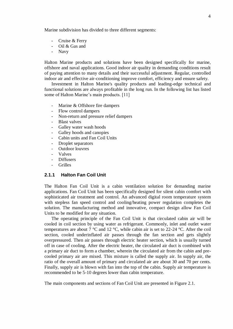
Marine subdivision has divided to three different segments:
- Cruise & Ferry
- Oil & Gas and
- Navy
Halton Marine products and solutions have been designed specifically for marine,
offshore and naval applications. Good indoor air quality in demanding conditions result
of paying attention to many details and their successful adjustment. Regular, controlled
indoor air and effective air-conditioning improve comfort, efficiency and ensure safety.
Investment in Halton Marine's quality products and leading-edge technical and
functional solutions are always profitable in the long run. In the following list has listed
some of Halton Marine’s main products. [11]
- Marine & Offshore fire dampers
- Flow control dampers
- Non-return and pressure relief dampers
- Blast valves
- Galley water wash hoods
- Galley hoods and canopies
- Cabin units and Fan Coil Units
- Droplet separators
- Outdoor louvres
- Valves
- Diffusers
- Grilles
2.1.1 Halton Fan Coil Unit
The Halton Fan Coil Unit is a cabin ventilation solution for demanding marine
applications. Fan Coil Unit has been specifically designed for silent cabin comfort with
sophisticated air treatment and control. An advanced digital room temperature system
with stepless fan speed control and cooling/heating power regulation completes the
solution. The manufacturing method and innovative, compact design allow Fan Coil
Units to be modified for any situation.
The operating principle of the Fan Coil Unit is that circulated cabin air will be
cooled in coil section by using water as refrigerant. Commonly, inlet and outlet water
temperatures are about 7 °C and 12 °C, while cabin air is set to 22-24 °C. After the coil
section, cooled underinflated air passes through the fan section and gets slightly
overpressured. Then air passes through electric heater section, which is usually turned
off in case of cooling. After the electric heater, the circulated air duct is combined with
a primary air duct to form a chamber, wherein the circulated air from the cabin and pre-
cooled primary air are mixed. This mixture is called the supply air. In supply air, the
ratio of the overall amount of primary and circulated air are about 30 and 70 per cents.
Finally, supply air is blown with fan into the top of the cabin. Supply air temperature is
recommended to be 5-10 degrees lower than cabin temperature.
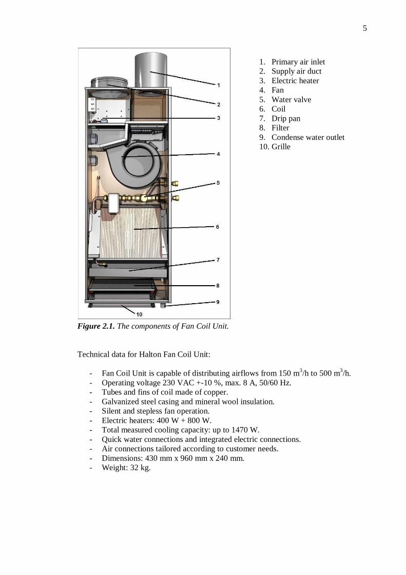
The main components and sections of Fan Coil Unit are presented in Figure 2.1.
5
1. Primary air inlet
2. Supply air duct
3. Electric heater
4. Fan
5. Water valve
6. Coil
7. Drip pan
8. Filter
9. Condense water outlet
10. Grille
Figure 2.1. The components of Fan Coil Unit.
Technical data for Halton Fan Coil Unit:
- Fan Coil Unit is capable of distributing airflows from 150 m3/h to 500 m
3/h.
- Operating voltage 230 VAC +-10 %, max. 8 A, 50/60 Hz.
- Tubes and fins of coil made of copper.
- Galvanized steel casing and mineral wool insulation.
- Silent and stepless fan operation.
- Electric heaters: 400 W + 800 W.
- Total measured cooling capacity: up to 1470 W.
- Quick water connections and integrated electric connections.
- Air connections tailored according to customer needs.
- Dimensions: 430 mm x 960 mm x 240 mm.
- Weight: 32 kg.

6
3 THEORY OF HEAT TRANSFER
All equations and functions, which are used in calculation tool, are presented in this
part. First of all, has presented some of the basic laws related to air and water vapour
mixtures. Psychrometry of air conditioning processes, comfort and design conditions,
air cooler coils, airflow in ducts and fan performance are presented as well.
3.1 Properties of air and water vapour mixtures
The most important thing for the student of psychrometry to understand from the outset
is that the working fluid under study is a mixture of two different gaseous substances.
One of these, dry air, is itself a mixture of gases, and the other, water vapour, is steam in
the saturated or superheated condition. Some of the most important standards are,
- Density of air, ρair 1,296 kg/m3 for dry air at 101325 Pa and 0 °C.
- Density of water, ρwater 999,9 kg/m3 at 0 °C and
- Barometric pressure, patm 101325 Pa in 0 °C. [3][10]
3.1.1 The general gas law
The general gas law is expressed as:
TRmVp (3.1.1)
where p is the pressure of the gas in Pa, V is the volume of the gas in m3, m is the mass
of the gas in kg, R is a specific gas constant in J/(kg×K) and T is the absolute
temperature of the gas in K.
Avogadro´s hypothesis argues that equal volumes of all gases at the same
temperature and pressure contain the same number of molecules. Accepting this and
taking as the unit of mass the kilomole (kmol), a mass in kilograms numerically equal to
the molecular mass of the gas, a value for the universal gas constant can be established:
TRVp om (3.1.2)
where Vm is the molar volume in m3/kmol and is the same for all gases having the same
values of p and T. Using the values p is 101325 Pa and T is 273,15 K, it has been
experimentally determined that Vm equals 22,41 m3/kmol. Hence the universal gas
constant, Ro, is determined
Kkmol
J
K
kmolmPa
T
VpR m
o
41,831415,273
/41,22*101325 3
7
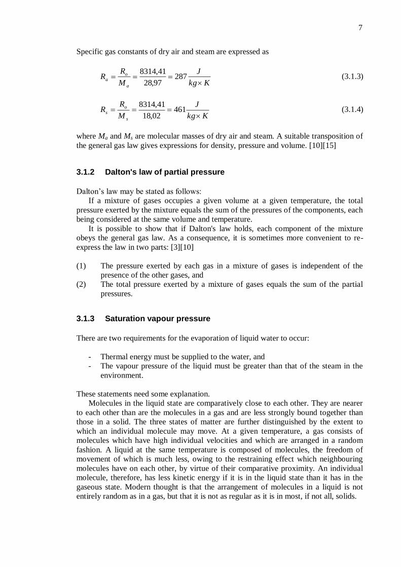
Specific gas constants of dry air and steam are expressed as
Kkg
J
M
RR
a
o
a
28797,28
41,8314 (3.1.3)
Kkg
J
M
RR
s
o
s
46102,18
41,8314 (3.1.4)
where Ma and Ms are molecular masses of dry air and steam. A suitable transposition of
the general gas law gives expressions for density, pressure and volume. [10][15]
3.1.2 Dalton's law of partial pressure
Dalton’s law may be stated as follows:
If a mixture of gases occupies a given volume at a given temperature, the total
pressure exerted by the mixture equals the sum of the pressures of the components, each
being considered at the same volume and temperature.
It is possible to show that if Dalton's law holds, each component of the mixture
obeys the general gas law. As a consequence, it is sometimes more convenient to re-
express the law in two parts: [3][10]
(1) The pressure exerted by each gas in a mixture of gases is independent of the
presence of the other gases, and
(2) The total pressure exerted by a mixture of gases equals the sum of the partial
pressures.
3.1.3 Saturation vapour pressure
There are two requirements for the evaporation of liquid water to occur:
- Thermal energy must be supplied to the water, and
- The vapour pressure of the liquid must be greater than that of the steam in the
environment.
These statements need some explanation.
Molecules in the liquid state are comparatively close to each other. They are nearer
to each other than are the molecules in a gas and are less strongly bound together than
those in a solid. The three states of matter are further distinguished by the extent to
which an individual molecule may move. At a given temperature, a gas consists of
molecules which have high individual velocities and which are arranged in a random
fashion. A liquid at the same temperature is composed of molecules, the freedom of
movement of which is much less, owing to the restraining effect which neighbouring
molecules have on each other, by virtue of their comparative proximity. An individual
molecule, therefore, has less kinetic energy if it is in the liquid state than it has in the
gaseous state. Modern thought is that the arrangement of molecules in a liquid is not
entirely random as in a gas, but that it is not as regular as it is in most, if not all, solids.

8
It is evident that if the individual molecular kinetic energies are greater in the
gaseous state, then energy must be given to a liquid when it is changing to the gaseous
phase. This explains the first stated requirement for evaporation.
As regards the second requirement, the situation is clarified if one considers the
boundary between a vapour and its liquid. Only at this boundary can a transfer of
molecules between the liquid and the gas occur. Molecules at the surface have a kinetic
energy, which has a value related to the temperature of the liquid. Molecules within the
body of the gas also have a kinetic energy, which is a function of the temperature of the
gas. Those gaseous molecules near the surface of the liquid will, from time to time, tend
to hit the surface of the liquid, some of them staying there. Molecules within the liquid
and near to its surface will, from time to time, also tend to leave the liquid and enter the
gas, some of them staying there.
It has been found that water in an ambient gas which is not pure steam but a mixture
of dry air and steam, behaves in a similar fashion, and that for most practical purposes
the relationship between saturation temperature and saturation pressure is the same for
liquid water in contact only with steam. One concludes from this a very important fact:
saturation vapour pressure depends solely upon temperature. [10]
3.1.4 Moisture content and relative humidity
Moisture content is defined as the mass of water vapour in kg, which is associated with
one kilogram of dry air in an air-water vapour mixture.
a
s
m
mmcontentMoisture (3.1.5)
Relative humidity is a term used to describe the amount of water vapour in a mixture of
air and water vapour. It is defined as the ratio of the partial pressure of water vapour in
the air-water mixture to the saturated vapour pressure of water at those conditions. The
relative humidity of air depends not only on temperature but also on pressure of the
system of interest. Relative humidity is often used instead of absolute humidity in
situations where the rate of water evaporation is important, as it takes into account the
variation in saturated vapour pressure. [4]
Relative humidity is defined as
%100ss
s
p
pΦratioHumidity (3.1.6)
where ps is a pressure of water vapour and pss is the saturation vapour pressure
3.1.5 Dew point and specific volume of the mixture
The dew point is the temperature to which a given parcel of humid air must be cooled,
at constant barometric pressure, for water vapour condense into liquid water. The
condensed water is called dew when it forms on a solid surface. The dew point is a
saturation temperature.
9
The dew point is associated with relative humidity. A high relative humidity
indicates that the dew point is closer to the current air temperature. Relative humidity of
100 % indicates the dew point is equal to the current temperature and the air is
maximally saturated with water. When the dew point remains constant and temperature
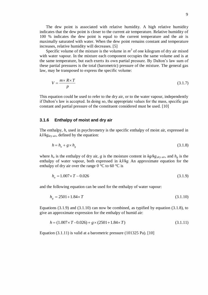
increases, relative humidity will decreases. [5] Specific volume of the mixture is the volume in m
3 of one kilogram of dry air mixed
with water vapour. In the mixture each component occupies the same volume and is at
the same temperature, but each exerts its own partial pressure. By Dalton’s law sum of
these partial pressures is the total (barometric) pressure of the mixture. The general gas
law, may be transposed to express the specific volume:
p
TRmV
(3.1.7)
This equation could be used to refer to the dry air, or to the water vapour, independently
if Dalton’s law is accepted. In doing so, the appropriate values for the mass, specific gas
constant and partial pressure of the constituent considered must be used. [10]
3.1.6 Enthalpy of moist and dry air
The enthalpy, h, used in psychrometry is the specific enthalpy of moist air, expressed in
kJ/kgdry air, defined by the equation:
ga hghh (3.1.8)
where ha is the enthalpy of dry air, g is the moisture content in kg/kg,dry air, and hg is the
enthalpy of water vapour, both expressed in kJ/kg. An approximate equation for the
enthalpy of dry air over the range 0 °C to 60 °C is
026.0007.1 Tha (3.1.9)
and the following equation can be used for the enthalpy of water vapour:
Thg 84.12501 (3.1.10)
Equations (3.1.9) and (3.1.10) can now be combined, as typified by equation (3.1.8), to
give an approximate expression for the enthalpy of humid air:
)1.84 (2501 0.026)-(1.007 TgTh (3.1.11)
Equation (3.1.11) is valid at a barometric pressure (101325 Pa). [10]

10
3.2 The Psychrometry of Air Conditioning Processes
This chapter provides a picture of the way in which the state of moist air alters as an air
conditioning process takes place or a physical change occurs. Familiarity with the
psychrometric chart is essential for a proper understanding of air conditioning.
Any point on the chart is termed a state point, the location of which, at a given
barometric pressure, is fixed by any two of the psychrometric properties. It is customary
and convenient to design charts at a constant barometric pressure because barometric
pressure does not alter greatly over much of the inhabited surface of the earth. [10]
Figure 3.1. Psychrometric chart by CIBSE. [16]
The psychrometric chart published by the CIBSE (Figure 3.1) uses two fundamental
properties, mass and energy, in the form of moisture content and enthalpy, as co-
ordinates. As a result, mixture states lie on the straight line that joins the state points of
the two constituents. Lines of constant dry-bulb temperature are virtually straight but
divergent, only the isotherm for 30 °C being vertical. The reason for this is that to
preserve the usual appearance of a psychrometric chart, in spite of choosing the two
fundamental properties as co-ordinates, the co-ordinate axes are oblique, not
rectangular. Hence, lines of constant enthalpy are both straight and parallel, as are lines
of constant moisture content. Since both these properties are taken as linear, the lines of
constant enthalpy are equally spaced as are the lines of constant moisture content. This
is not true of the lines of constant humid volume and constant wet-bulb temperature,
which are slightly curved and divergent. Since their curvature is only slight in the region
of practical use on the chart, they can be regarded as straight without significant error
resulting. In the sketches of psychrometric charts used throughout this text to illustrate
changes of state, only lines of percentage saturation are shown curved. All others are
shown straight, and dry-bulb isotherms are shown as vertical, for convenience. [10]
The chart also has a protractor, which allows the value of the ratio of the sensible
heat gain to the total heat gain to be plotted on the chart. This ratio is an indication of

11
the slope of the room ratio line and is of value in determining the correct supply state of
the air that must be delivered to a conditioned space. The zero value for the ratio is
parallel to the isotherm for 30 °C because the enthalpy of the added vapour depends on
the temperature at which evaporation takes place, it being assumed that most of the
latent heat gain to the air in a conditioned room is by evaporation from the skin of the
occupants and that their skin surface temperature is about 30 °C. [10] The psychrometric chart by CIBSE is such a system with oblique co-ordinates. For
this chart then, a principle can be stated for the expression of mixture states. When two
air streams mix adiabatically, the mixture state lies on the straight line which joins the
state points of the constituents, and the position of the mixture state point is such that
the line is divided inversely as the ratio of the masses of dry air in the constituent air
streams. [10]
3.2.1 Sensible heating and cooling
Sensible heat transfer occurs when moist air flows over the coils of a sensible heater or
cooler. In sensible cooling there is a following restriction: the lowest water temperature
must not be so low that moisture starts to condense on the cooler coils. If such
condensation does occur, through a poor choice of chilled water temperature, then the
process will no longer be one of sensible cooling since dehumidification will also be
taking place. [10]
The variations in the physical properties of the moist air, for the two cases, are
summarized below:
Sensible heating Sensible cooling
Dry-bulb increases decreases
Enthalpy increases decreases
Humid volume increases decreases
Wet-bulb increases decreases
Percentage saturation decreases increases
Moisture content constant constant
Dew point constant constant
Vapour pressure constant constant
3.2.2 Dehumidification
There are four principal methods whereby moist air can be dehumidified:
(i) cooling to a temperature below the dew point,
(ii) adsorption,
(iii) absorption and
(iv) compression followed by cooling.
The first method forms the subject matter of this section.
Cooling to a temperature below the dew point has done by passing the moist air over
a cooler coil provided with chilled water. Figure 3.2. shows on a sketch of a
psychrometric chart what happens when moist air is cooled and dehumidified in this
fashion. Since dehumidification is the aim, some part of the cooler coil must be at a
temperature less than the dew point of the air entering the equipment. In the Figure 3.2,

12
td is the dew point of the moist air and temperature tc corresponding to the point C on
the saturation curve, this is termed the mean coil surface temperature.
Figure 3.2. Cooling and dehumidification by a cooling coil.
For purposes of carrying out air conditioning calculations, it is sufficient to know
the state A of the moist air entering the coil, the state B of the air leaving the coil, and
the mass flow of the air.
It can be seen from Figure 3.2, that the moisture content of the air is reduced, as also
is its enthalpy and dry-bulb temperature. The percentage saturation, of course, increases.
Any of the cooler coil could not be 100 per cent efficient, which means that humidity on
state B is never as much as 100 per cent. It is unusual to speak of the efficiency of a
cooler coil. Instead, the alternative terms, contact factor and by-pass factor, are used.
They are complementary values and contact factor, sometimes denoted by , is defined
as
ca
ba
ca
ba
ca
ba
-tt
-tt
-hh
-hh
-gg
-gg (3.2.1)
Similarly, by-pass factor is defined as
ca
cb
ca
cb
ca
cb
-tt
-tt
-hh
-hh
-gg
-gg )1( (3.2.2)
13
Typical values of contact factor are 0.82 to 0.92 for practical coil selection. In hot,
humid climates more heat transfer surface is necessary and higher contact factors are
common. [10]
3.2.3 Cooling and dehumidification with reheat
When a cooler coil is used for dehumidification, the temperature of the moist air is
reduced, but it is quite likely that under these circumstances this reduced temperature is
too low. Although, we usually arrange that under conditions of maximum loads, both
latent and sensible, the state of the air leaving the cooler coil is satisfactory. This is not
so for partial load operation. The reason for this is that latent and sensible loads are
usually independent of each other. Consequently, it is sometimes necessary to arrange
for the air that has been dehumidified and cooled by the cooler coil to be reheated to a
temperature consistent with the sensible cooling load; the smaller the sensible cooling
load, the higher the temperature to which the air must be reheated. [10]
3.2.4 Pre-heat and humidification with reheat
Air conditioning units that handle primary air only may be faced in winter with the task
of increasing both the moisture content and the temperature of the air they supply to the
conditioned space. Humidification is needed because the outside air in winter has a low
moisture content, and if this air were to be introduced directly to the room there would
be a correspondingly low moisture content as well. The low moisture content may not
be intrinsically objectionable, but when the air is heated to a higher temperature its
relative humidity may become quite low. For example, outside air in winter might be at
-1 °C, saturated. The moisture content at this state is only 3.484 g/kgdry air. If this is
heated to 20 °C dry-bulb, and if there is a moisture pick-up in the room of 0.6 g/kgdry air,
due to latent heat gains, then the relative humidity in the room will be as low as 28 %.
This value may sometimes be seen as too low for comfort. The unit must increase the
temperature of the air, either to the value of the room temperature if there is background
heating to offset fabric losses, or to a value in excees of this if it is intended that the air
delivered should deal with fabric losses. [10]
3.3 Comfort and Design Conditions
For comfort, indoor air quality may be said to be acceptable if not more than 50 % of
the occupants can detect any odour and not more than 20 % experience discomfort, and
not more than 10 % suffer from mucosal irritation, and not more than 5 % experience
annoyance, for less than 2 % of the time. [10]
Air humidity affects the evaporation of water from the mucosal and sweating bodily
surfaces, influencing its diffusion through the skin. Low humidities, with dew points
less than 2 °C, tend to give a dry nose and throat, and eye irritation. A dusty
environment can exacerbate low humidity skin conditions. [7][10]
14
3.3.1 The choice of inside design conditions
For a person to feel comfortable it appears that the following conditions are desirable:
(1) The air temperature should be between 22-24 °C.
(2) The average air velocity in the room should not exceed 0.15 m/s in an air
conditioned room.
(3) Relative humidity should desirably lie between about 45 % and 60 %.
(4) The dew point should never be less than 2 °C.
(5) The temperature difference between the feet and the head should be as small as
possible, normally not exceeding 1.5 °C.
(6) Floor temperatures should not be greater than 26 °C when people are standing
and probably not less than 17 °C.
(7) The radiant temperature asymmetry should not be more than 5 °C vertically or
10 °C horizontally.
(8) The carbon dioxide content should not exceed about 0.1 %.
The two most important variables are dry-bulb temperature and air velocity, with mean
radiant temperature of slightly less importance. Of these a comfort air conditioning
system can only exercise direct automatic control over the dry-bulb temperature. A
suitable choice of air velocity may be achieved by proper attention to the system of air
distribution and acceptable values of mean radiant temperature should result from co-
operation between the design engineer and the architect, aiming to eliminate
objectionable radiant effects from sunlit windows in summer, cold windows in winter,
cold exposed floors or walls, and excessive radiation from light fittings.
The choice of inside comfort design conditions for an air conditioned room depends
on the physiological considerations already debated and on economic factors. The
designer then examines the outside design state, the clothing worn by the occupants,
their rate of working and the period of occupancy. An air temperature of 22 °C with
about 50 % relative humidity is a comfortable choice for long-term occupancy by
normally clothed, sedentary people but the humidity can be allowed to rise to 60 % or to
fall towards 40 %, under conditions of peak summer heat gains if psychrometric,
commercial or other practical considerations warrant it. [7][10]
3.3.2 Design temperatures and heat gains
The choice of inside and outside summer dry-bulb design temperatures affects the heat
gains and hence influences the capital cost of the installation and its running cost, the
latter implying the energy consumption of the system. Any change in the room design
condition, particularly dry-bulb temperature, will have an effect on the comfort of the
occupants. Similarly, any change in the chosen outside dry-bulb temperature will
influence the system performance and the satisfaction given. Thus a relaxation of the
outside design dry-bulb temperature to a lower value may give a small reduction in the
sensible heat gains and the capital cost but this must be balanced against the fact that the
system will only be able to maintain the inside design conditions for a shorter period of
the summer. The relative merits of any such decisions must be carefully considered and
the client advised. [10]
15
3.3.3 Sensible heat removal
If there is a continuous source of heat having an output of Q in a hermetically sealed room the temperature within room, Troom will rise until the flow of heat through the walls, of area A and thermal transmittance U, equals the output of the source:
)outroom - TAU (TQ (3.3.1)
In which Tout is the outside air temperature. It then follows that,
Q/AU T T outroom (3.3.2)
and hence Troom will always exceed Tout. [10]
3.3.4 The specific heat capacity of humid air
The air supplied to a conditioned room in order to remove sensible heat gains occurring
therein, is a mixture of dry air and superheated steam. It follows that these two gases
being always at the same temperature because of the intimacy of their mixture, will rise
together in temperature as both offset the sensible heat gain. They will, however, offset
differing amounts of sensible heat because, first of all, their masses are different, and
secondly, their specific heats are different too. [10]
Consider 1 kg of dry air with associated moisture content of g kg of superheated
steam, supplied at temperature Tsupply in order to maintain temperature Troom in a room in
the presence of sensible heat gains of Q in kW. A heat balance equation can be written
thus:
)-T( T g) - T(T Q plyroomplyroom supsup 890.1012.11
Where 1,012 and 1,890 are the specific heats at constant pressure of dry air and steam
respectively. Rearrange the equation:
)-T( Tg) (Q plyroom sup89.1012.1 (3.3.3)
The expression (1.012+1.89×g) is sometimes called the specific heat of humid air.
Taking into account the small sensible cooling or heating capacity of the superheated
steam present in the supply air (or its moisture content) provides a slightly more
accurate answer to certain types of problem. Such extra accuracy may not be warranted
in most practical cases but it is worthy of consideration as an exercise in fundamental
principles. [10]
3.3.5 Latent heat removal
If the air in a room is not at saturation, then water vapour may be liberated in the room
and cause the moisture content of the air in the room to rise. Such a liberation of steam
is effected by any process of evaporation as, for example, the case of insensible
perspiration and sweating on the part of the people present. Since it is necessary to

16
provide heat to effects a process of evaporation, it is customary to speak of the addition
of moisture to a room as kW of latent heat rather than as kg/s of water evaporated. [10]
The heat gains occurring in a room can be considered in two parts: sensible gains
and latent gains. The mixture of dry air and associated water vapour supplied to a room
has therefore a dual role: it is cool enough initially to suffer a temperature rise up to the
room dry-bulb temperature in offsetting the sensible gains, and its initial moisture
content is low enough to permit a rise to the value of the room moisture content as latent
heat gains are offset. [10]
If the mass of dry air supplied and its associated moisture content is known, then it
is possible to calculate the rise in room moisture content corresponding to given latent
heat gains:
fgplyroom h) - g (g m t gain Latent hea sup (3.3.4)
where m is mass flow rate of supply air in kgdry air/s, groom and gsupply are the moisture
contents of the room and supply air in kgwater/kgdry air, and hfg is the latent heat of
evaporation in kJ/kgwater. [10]
3.3.6 Heat gain arising from fan power
The flow of air along a duct results in the air stream suffering a loss of energy. The
energy dissipated through the ducting system is apparent as a change in the total
pressure of the air stream and the energy input by the fan is indicated by the fan total
pressure. [10]
Ultimately, all energy losses appear as heat (although, on the way to this, some are
evident as noise, in duct systems). So an energy balance equation can be formed
involving the energy supplied by the fan and the energy lost in the air stream. That is to
say, the loss of pressure suffered by the air stream as it flows through the ducting
system and past the items of plant (which offer a resistance to airflow) constitutes an
adiabatic expansion which must be offset by an adiabatic compression at the fan. [10]
So, all the power supplied by the fan is regarded as being converted to heat and
causing an increase in the temperature of the air handled, t, as it flows through the fan.
A heat balance equation can be written:
/s)(m rate flow volumetric)m(N/ pressure fan totalpowerAir 32
The rate of heat gain corresponding to this is the volumetric flow rate × × Cp × t,
where and Cp are the density and specific heat of air, respectively. Hence
pCρ
) N/mpressure (fan total Δt
2
The air quantities have cancelled, indicating that the rise in air temperature is
independent of the amount of air handled, and using is 1,296 kg/m3 and Cp is 1007
J/(kg×K) we get

17
1305
2 ) N/mpressure (fan total Δt (3.3.5)
Thus, the air suffers a temperature rise of 0,000766 K for each N/m2 of fan total
pressure. [3][10]
The energy the fan receives is in excess of what it delivers to the air stream, since
frictional and other losses occur as the fan impeller rotates the air stream. The Power
input to the fan shaft is termed the Fan power and the ratio of the air power to the fan
power is termed the total fan efficiency and is denoted by . Not all the losses occur
within the fan casing. Some take place in the bearings external to the fan, for example.
Hence, for the case where the fan motor is not in the air stream, full allowance should
not be made. It is suggested that a compromise be adopted. [10]
If an assumption of 70 % is made for the fan total efficiency and if it is assumed
that, instead of 30 %, only 15 % of the losses are absorbed by the air stream (since some
are lost from the fan casing and the bearings) equation (3.3.5) becomes
8501305
2
,
) N/mpressure (fan total Δt
1109
2 ) N/mpressure (fan total Δt (3.3.6)
Thus almost one thousandth of a degree rise in temperature for each N/m2 of fan total
pressure results from the energy input at the fan. In other words, a degree rise occurs for
each kPa of fan total pressure. [10]
When the fan and motor are within the air stream, as is the case with many air
handling units, all the power absorbed by the driving motor is liberated into the air
stream. Full account must then be taken of the motor inefficiency as well as all the fan
inefficiency. Assuming a total fan efficiency of 70 % and a motor efficiency of 90 % the
temperature rise of the air stream is:
9.07.01305
2
) N/mpressure (fan total Δt
822
2 )N/mpressure (fan total Δt (3.3.7)
This represents a temperature rise of about 1.3 K for each kPa of fan total pressure.
[3][10]
3.3.7 Other heat gains
Heat gains are either sensible, tending to cause a rise in air temperature, or latent,
causing an increase in moisture content. In comfort air conditioning sensible gains
originate from the following sources:
18
(1) Solar radiation through windows, walls and roofs.
(2) Transmission through the building envelope and by the natural infiltration of
warmer air from outside.
(3) People.
(4) Electric lighting.
(5) Business machines and the like.
Latent heat gains are due to the presence of the occupants and the natural infiltration
of more humid air from outside. In the case of industrial air conditioning there may be
additional sensible and latent heat gains from the processes carried out. All the above
sources of heat gain are well researched but a measure of uncertainty is introduced by
the random nature of some, such as the varying presence of people and the way in
which electric lights are switched. The thermal inertia of the building structure also
introduces a problem when calculating the sensible heat gain arising from solar
radiation. It follows that a precise determination of heat gains is impossible.
Nevertheless, it is vital that the design engineer should be able to calculate the heat
gains with some assurance and this can be done when generally accepted methods of
calculation are followed, supported by sound common sense. [10]
3.4 Air Cooler Coils A cooler coil is not merely a heater battery fed with chilled water or into which cold,
liquid refrigerant is pumped. There are two important points of difference: at first, the
temperature differences involved are very much less for a cooler coil than for a heater
battery, and secondly, moisture is condensed from the air on to the cooler coil surface.
With air heaters, water entering and leaving at 85 °C and 65 °C respectively may be
used to raise the temperature of an air stream from 0 °C to 35 °C, resulting in a log
mean temperature difference of about 53 °C for a counter flow heat exchange. With a
cooler coil, water may enter at 7 °C and leave at 13 °C in reducing the temperature of
the air stream from 26 °C to 11 °C, a log mean temperature difference of only 7.6 °C
with counter flow operation. The result is that much more heat transfer surface is
required for cooler coils and it is important that counter flow heat exchange be obtained.
Chilled water coils are usually constructed of externally finned, horizontal tubes, so
arranged as to facilitate the drainage of condensed moisture from the fins. Tube
diameters vary from 8 to 25 mm, and copper is the material commonly used, with
copper or aluminium fins. Copper fins and copper tubes generally offer the best
resistance to corrosion, particularly if the whole assembly is electro-tinned after
manufacture. Fins are usually of the plate type, although spirally wound and circular
fins are also used. Cross flow heat exchange between the air and cooling fluid occurs for
a particular row but, from row to row, parallel flow or counter flow of heat may take
place, depending on the way in which the piping has been arranged. Counter flow
connection is essential for chilled water coils in all cases. In direct expansion coils,
since the refrigerant is boiling at a constant temperature the surface temperature is more
uniform and there is no distinction between the parallel flow and counter flow, the
logarithmic mean temperature difference being the same. [10]
All cooler coils should be divided into sections by horizontal, independently
drained, condensate collection trays running across their full width and depth. Opinions
seem to differ among manufacturers as to the maximum permissible vertical spacing
between condensate drip pans. Clearly it depends on the sensible-total heat ratio (the
smaller this is the greater the condensation rate), the spacing between the fins (the

19
narrower the spacing the more difficult it is for the condensate to drain freely) and the
face velocity (the faster the airflow the more probable the carryover of condensate). Fin
spacing in common use are 316 to 476 per metre and the thicknesses used lie between
0.15 and 0.42 mm. Thinner fins, incidentally, tend to grip the tube less tightly at their
roots and perhaps give poorer heat transfer. Fins may be corrugated or smooth, the
former reducing the risk of carryover while improving the heat transfer by a small
increase in the surface area of the fins. An analysis of manufacturers' data suggests that
for cooling coils having sensible-total heat ratios of not less than 0.65. [10]
For sensible-total ratios less than 0.65 should not be used. Coils with sensible-total
ratios exceeding 0.98 are virtually doing sensible cooling only and the risk of
condensate carryover is slight. Water velocities in use are between 0.6 and 2.4 m/s, in
which range the coils are self-purging of air. Water pressure drops are usually between
15 and 150 kPa and air pressure drops are dependent on the number of rows and the
piping and finning arrangements. A coil that is doing no latent cooling offers about one-
third less resistance to airflow. [10]
Careless handling in manufacture, delivery to site and erection often causes damage
to the coil faces, forming large areas of turned-back fin edges that disturb the airflow,
collect dirt from the air stream and increase the air pressure drop. The fins in such
damaged areas must be combed out after installation before the system is set to work.
Other materials are sometimes used for air cooler coils but ordinary steel coils
should never be used because of the rapid corrosion likely. Stainless steel is sometimes
used but it is expensive and, because its thermal conductivity is less than that of copper,
more heat transfer surface is required. [10]
Air cooler coils tend to be wide and short, rather than narrow and tall. This is
because it is cheaper to make coils with this shape, there is being fewer return bend
connections to make (where tubes emerge from the coil easing). It is also because a
short coil drains condensate away more easily: with a tall coil there is the likelihood of
condensate building up between the fins at the bottom of the coil, inhibiting airflow and
heat transfer and increasing the risk of condensate carry-over into the duct system. [10]
A consequence of the wide shape of cooler coil faces is that airflow over them is
likely to be uneven, the air stream tending to flow over the middle of the coil face. [10]
Galvanised steel casings are often used for coils with copper tubes and copper or
aluminium fins. This is a poor combination since copper and zinc in conjunction with
slightly acidic condensate favour electrolytic corrosion. If possible, other materials
should be used for cooler coil casings. Drain cocks and air vents should always be
provided for cooler coils using chilled water or brine. [10]
3.4.1 Parallel and counter flow
Although ordinary heat exchangers may be extremely different in design and
construction and may be of the single- or two-phase type, their modes of operation and
effectiveness are largely determined by the direction of the fluid flow within the
exchanger. The most common arrangements for flow paths within a heat exchanger are
counter flow and parallel flow. [10]

20
Figure 3.3. Counter flow. The points 0, 4 and A are in a straight line and A lies on the
100 % saturation curve. A is the apparatus dew point and its temperature, Tsm, is the
mean coil surface temperature for the whole four rows of the coil.
A counter flow heat exchanger (see Figure 3.3) is one in which the direction of the
water flow is opposite to the direction of the airflow, due to this the heat transfer is
almost equal in every different rows of coil. A line joining the state points 0, 1, 2, 3 and
4 is a convex curve and represents the change of state of the air as its flows past the
rows under counter flow conditions. A straight line joining the points 0 and 4 indicates
the actual overall performance of the coil. This condition line replacing the condition
curve, cuts the saturation curve at a point A when produced. [10]
Similar considerations apply when parallel flow is dealt with (Figure 3.4), but the
result is different. A concave condition curve is obtained by joining the points 0, 1, 2, 3
and 4. Flow direction of water and air are same for both in parallel flow, which means
that most of the heat transfer happens in the row number 1 and the least in row number
4. When comparing these two methods, could be said that, a lower leaving air
temperature is achieved, greater heat transfer occurs, and the coil is more efficient, if it
is piped for counter flow operation. Due of these things, counter flow configuration is
commonly used method in cooling coils. [10]

21
Figure 3.4. Parallel flow. The points 0, 4 and A are in a straight line. A is the apparatus
dew point and its temperature is the mean coil surface temperature, Tsm.
3.4.2 Contact factor
Such a definition is not always useful-for example, in a cooler coil for sensible cooling
only-and so it is worth considering another approach, in terms of the heat transfer
involved, that is in some respects more informative though not precise.
22
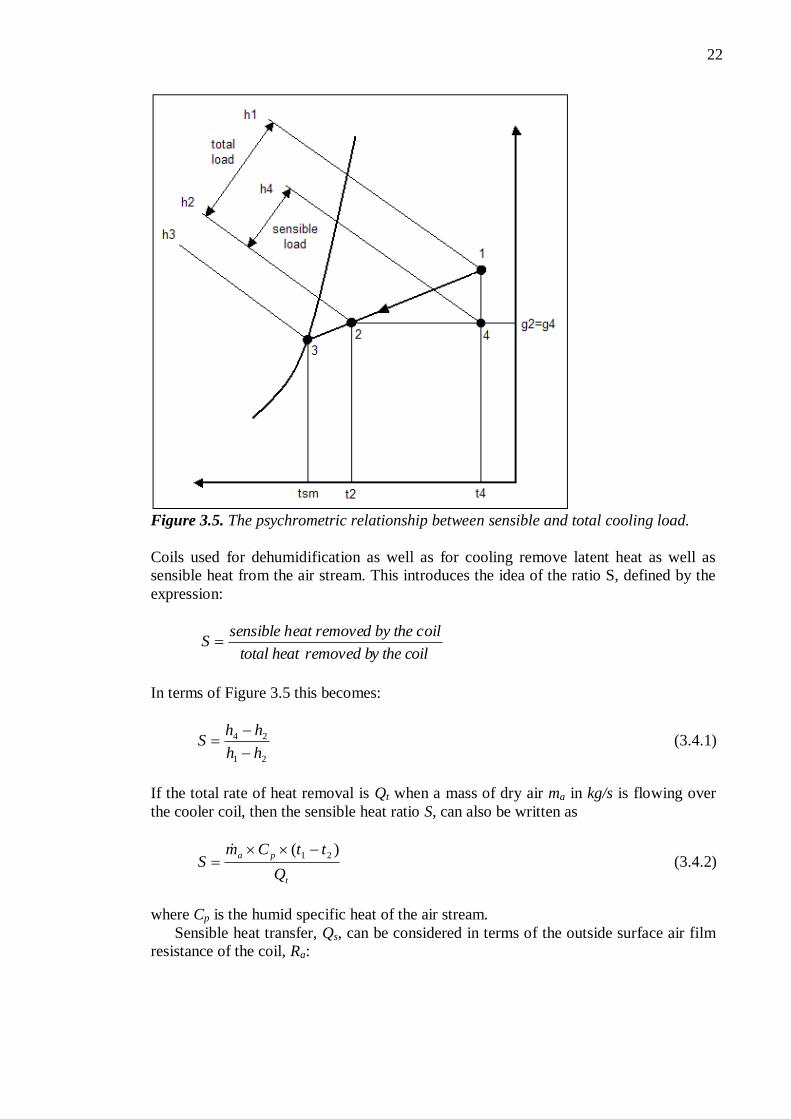
Figure 3.5. The psychrometric relationship between sensible and total cooling load.
Coils used for dehumidification as well as for cooling remove latent heat as well as
sensible heat from the air stream. This introduces the idea of the ratio S, defined by the
expression:
y the coil removed btotal heat
oild by the ceat removesensible hS
In terms of Figure 3.5 this becomes:
21
24
hh
hhS
(3.4.1)
If the total rate of heat removal is Qt when a mass of dry air ma in kg/s is flowing over
the cooler coil, then the sensible heat ratio S, can also be written as
t
pa
Q
ttCmS
)( 21
(3.4.2)
where Cp is the humid specific heat of the air stream.
Sensible heat transfer, Qs, can be considered in terms of the outside surface air film
resistance of the coil, Ra:

23
a
tas
sR
ALMTDttvQ
2125.1 (3.4.3)
where v is volumetric flow rate in m3/s, At is the total external surface area of the coil in
m2
and LMTDas is the logarithmic mean temperature difference between the air stream
and the mean coil surface temperature, Tsm.
smsm
smsmas
TtTt
TtTtLMTD
21
21
/ln
)()( (3.4.4)
Equation (3.4.3) then becomes
a
t
smsm
sR
A
TtTt
ttQ
21
21
/ln (3.4.5)
and therefore
a
t
smsm R
A
TtTt
ttttv
21
2121
/ln)(25.1
whence
vR
A
Tt
Tt
a
t
sm
sm
25.1ln
2
1 (3.4.6)
Since v equals Afvf, where Af and vf are the face area and face velocity entering the
cooler coil in m/s, respectively, equation (3.4.6) becomes
kvRA
A
Tt
Tt
faf
t
sm
sm
25.1ln
2
1 (3.4.7)
k is a constant for a given coil and face velocity but it takes no account of heat transfer
through the inside of the tubes. We can now write:
)exp(1
2 kTt
Tt
sm
sm
If r is the number of rows and Ar is the total external surface area per row, At is Ar r
and k becomes (Ar/Af)(r)/(Ra1,25vf). An approximate expression for the contact
factor now emerges:
faf
r
vR
r
A
A
25.1exp1 (3.4.8)
Note that the contact factor is independent of the psychrometric state and the coolant
temperature, provided that the mass flow ratio of air to water remains constant. [10]

24
3.4.3 Heat and mass transfer to cooler coils
LMTD-method
Heat and mass transfer to a cooler coil involves three stages: heat flows from the air
stream to the outer surface of the fins and tubes, it is then transferred through the metal
of the fins and the wall of the tubing, and finally, it passes from the inner walls of the
tubes through the surface film of the cooling fluid to the main stream of the coolant. In
general, dehumidification occurs as well as cooling so that the behaviour of cooler coils
cannot be described in simple terms. A very approximate approach, adopted by some
manufacturers, is to establish a U-value for the coil that is given a bias to account for the
extra heat flow by virtue of condensation. The duty is described by:
awttt LMTDAUQ (3.4.9)
Where Ut is the biased U-value, At the total external surface area and LMTDaw is the
logarithmic mean temperature difference between the air stream and the water flowing,
defined by:
) - t) / (t - t(t
) - t) - (t - t(tLMTD
wawbl
wawbl
aw
2
2
ln (3.4.10)
using the notation of Figure 3.5. The biased thermal transmission coefficient is
expressed by
wmat RRSRR/U 1 (3.4.11)
where Ra is the thermal resistance of the air film when the external surface is dry, S is
the sensible-total heat transfer ratio, Rm is the thermal resistance of the tubes Rt plus the
fins Rf, and Rw is the resistance of the water film within the tubes. Rw must multiplied by
the ratio At/Ai, where At is the total external surface area and Ai is the internal surface
area, so that it refers to the total external surface area. R is the total thermal resistance,
air to water. [10]
Ra is the reciprocal of the sensible heat transfer coefficient on the air side, ha, which
depends principally on the mass flow rate of the air stream. For standard air, a staggered
arrangement of tubes, ha is: [8]
8.0
42.27 fa vh (3.4.12)
If the coil is only partially wet then there are two U-values: one using SRa in equation
(3.4.11) and referring to the wetted part of the external surface, and the other using Ra in
the equation and referring to the dry part of the surface. The resistance of the fins when
dry:
af Rη
ηR
1 (3.4.13)
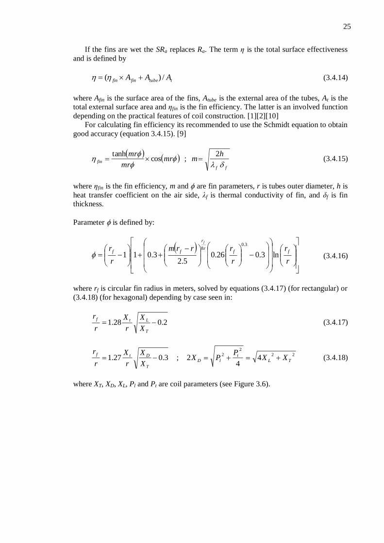
25
If the fins are wet the SRa replaces Ra. The term η is the total surface effectiveness
and is defined by
ttubefinfin AAA /)( (3.4.14)
where Afin is the surface area of the fins, Atube is the external area of the tubes, At is the
total external surface area and ηfin is the fin efficiency. The latter is an involved function
depending on the practical features of coil construction. [1][2][10]
For calculating fin efficiency its recommended to use the Schmidt equation to obtain
good accuracy (equation 3.4.15). [9]
ff
fin
hmmr
mr
mr
2;cos
tanh (3.4.15)
where ηfin is the fin efficiency, m and are fin parameters, r is tubes outer diameter, h is
heat transfer coefficient on the air side, λf is thermal conductivity of fin, and δf is fin
thickness.
Parameter is defined by:
r
r
r
rrrm
r
r ffr
r
ff
f
ln3.026.05.2
3.011
3.08
(3.4.16)
where rf is circular fin radius in meters, solved by equations (3.4.17) (for rectangular) or
(3.4.18) (for hexagonal) depending by case seen in:
2.028.1 T
Ltf
X
X
r
X
r
r (3.4.17)
22
2
24
42;3.027.1 TL
t
lD
T
DtfXX
PPX
X
X
r
X
r
r (3.4.18)
where XT, XD, XL, Pl and Pt are coil parameters (see Figure 3.6).

26
Figure 3.6. Unit cells for inline and staggered tube layouts with plain plate fins. [9]
Using copper as a material instead of aluminium improves efficiency but the use of
larger diameter tubing reduces it.
The resistance of the metal of the tubes, Rt, referred to the total external surface are,
is defined by
i
o
t
o
i
t
td
d
λ
d
A
AR ln
2 (3.4.19)
wherein At/Ai is the ratio of the total external surface to the total internal surface area, λt
is the thermal conductivity of the metal of the tubes, do is the outer tube diameter and di
its inner diameter, both in meters.
The thermal resistance of the water film inside the tubes, Rw, referred to their inner
surface area, is given by the following:
8.02.09.201429 vt/dR wmiw (3.4.20)
in which twm is the mean water temperature, v is the mean water velocity and di is the
inside diameter of the tube in metres. [1][10]
The method of enhancing the U-value of a cooler coil in order to account for the
dehumidification occurring, cannot be regarded as anything other than very
approximate. Some of the reasons are:
(a) The heat transfer is cross flow for any particular row, even though it is counter
flow from row to row. Hence the logarithmic mean temperature difference used
in the foregoing should be modified to take account of this.
(b) The airflow distribution over the face of the coil is not uniform, being
concentrated in the centre with a tendency to stagnation at the corners. Hence the

27
value of the heat transfer coefficient through the air film, ha, is not uniform over
the coil face.
(c) The use of the sensible-total heat transfer ratio, S, must be regarded as an
approximation to account for dehumidification.
(d) It is probable that not all the external surface of the fins and tubes is wet with
condensate.
(e) The U-value is not constant throughout the cooler coil.
(f) The psychrometric state of the air leaving the coil is not uniform across the face
and hence calculations based on a single state will not be precise.
ε– NTU method
The LMTD -method may be applied to design problems for which the fluid flow rates
and inlet temperatures, as well as a desired outlet temperature, are prescribed. For a
specified coil type, the required surface area, as well as the other outlet temperature, are
readily determined. If the LMTD -method is used in performance calculations for which
both outlet temperatures must be determined from knowledge of the inlet temperatures,
the solution procedure is iterative. For both, design and performance calculations, ε–
NTU (the effectiveness-Number of Transfer Units) -method may be used without
iteration. [3][12]
Heat exchanger effectiveness ε, is defined as
10,max
q
q (3.4.21)
where q is the total capacity of heat exchanger, and qmax is maximum possible heat rate
of heat exchanger, defined as
incoldinhot TTCq ,,minmax (3.4.22)
where Thot,in is inlet temperature of hot fluid, and Tcold,in is inlet temperature of cold
fluid. Cmin is the smaller one of heat capacity rates Chot and Ccold.
The effectiveness depends of heat exchanger type, for a counter flow configuration,
the effectiveness can be calculated from the following equation,
r
r
CNTU
r
CNTU
C
1
1
exp1
exp1 (3.4.23)
and for parallel flow configuration,
r
CNTU
C
r
1
exp11
(3.4.24)
where NTU, is dimensionless parameter, Number of Transfer Units, and Cr is the critical
heat capacity rate of fluids. These both parameters can be calculated from the equations
(3.4.25) and (3.4.26).

28
max
min
C
CCr (3.4.25)
minC
UANTU (3.4.26)
where U is U-value of coil and A is coil surface area. [3][12]
3.5 Fan performance and airflow in ducts
The most prevalent type of fan used in the HVAC industry, and in Fan Coil Units today
is a centrifugal fan. They are usually cheaper than axial fans and simpler in
construction. A centrifugal fan is a mechanical device for moving air or other gases with
a very low increase in pressure. These fans increase the speed of air stream with the
rotating impeller. They use the kinetic energy of the impeller or the rotating blade to
increase the pressure of the air stream which in turn moves them against the resistance
caused by ducts, dampers and other components. Centrifugal fans accelerate air radially,
changing the direction (typically by 90°) of the airflow. They are sturdy, quiet, reliable,
and capable of operating over a wide range of conditions. [10]
Centrifugal fan is a constant volume device, meaning that, at a constant fan speed, a
centrifugal fan will pump a constant volume of air rather than a constant mass. This
means that the air velocity in a system is fixed even though mass flow rate through the
fan is not. [14]
When a cylinder of air flows through a duct of circular section its core moves more
rapidly than its outer annular shells, these being retarded by the viscous shear stresses
set up between them and the rough surface of the duct wall. As flow continues, the
energy level of the moving air stream diminishes, the gas expanding as its pressure falls
with frictional loss. The energy content of the moving air stream is in the kinetic and
potential forms corresponding to the velocity and static pressures. If the section of the
duct remains constant then so does the mean velocity and hence, the energy transfer is at
the expense of the static pressure of the air. The magnitude of the loss is expressed as a
function of the Reynolds number Re, which is given by:
d / v V Re (3.5.1)
where V is the mean velocity of airflow, d is the duct diameter, and the kinematic
viscosity of the air. Generally, laminar flow can be expected if the Reynolds number is
less than about 2300. Fully turbulent flow exists when Reynolds number is more than
10000. Between 2300 and 10000, the flow is in a transition state and predictions are
unreliable. [10][12]
When air flows through a system of duct and plant, the prime source of energy to
compensate the losses incurred by friction and turbulence is the total pressure of the air
stream, defined by a simplified form of Bernoulli's theorem:
vppp st (3.5.2)

29
where pt is total pressure, ps is static pressure, and pv is velocity (or dynamic) pressure.
The velocity pressure corresponds to the kinetic energy of the air stream and the static
pressure corresponds to its potential energy. [10]
For the air stream to flow through the system of plant and ductwork, in spite of the
losses from friction and turbulence, the total energy on its upstream side must exceed
the total energy on its downstream side. If a pressure, p, propels a small quantity of air,
q, through a duct in a short time, t, against a frictional resistance equal and opposite
to p, then the rate at which energy must be fed into the system to continue the flow is
p(q/t). This is termed the air power, Pair, and is delivered to the air stream by the fan
impeller.
Air power = force × distance per unit time
= pressure in N / m2 × area in m
2 × velocity in m / s
= fan total pressure in N / m2 × volumetric airflow rate in m
3 / s
v P P tFair (3.5.3)
where PtF is fan total pressure in Pa (see equation 3.5.5), and v is volumetric airflow
rate in m3/s. [10]
In its passage through a fan the air stream suffers various losses, for example
bearing losses. It follows that the power input to the fan shaft must exceed the output
from the impeller to the air stream. The ratio of impeller output to shaft input is termed
the total fan efficiency, t and this provides a definition of fan power:
t
air
fanη
P P (3.5.4)
The air power delivered to the air stream provides for the sum of the following:
The acceleration of outside air from rest to the velocity in the air intake, the
frictional resistance of the air inlet louvres, the energy losses incurred by turbulence
formed in the vena-contracta at entry, the frictional resistance by each item of plant,
frictional resistance in the ducts and duct fittings, the frictional resistance of the index
grille, losses incurred by the presence of turbulence anywhere in the system and the
kinetic energy loss from the system (represented by the mass of moving air delivered
from the index grille). [10]
The energy loss by friction and turbulence would cause a temperature rise in the air
stream if it were not exactly offset by the fall in temperature resulting from the adiabatic
expansion accompanying the pressure drop. The only temperature rise occurs at the fan,
where adiabatic compression takes place. The power absorbed by the electric driving
motor must exceed the fan power, during steady-state operation, because of the loss in
the drive between the fan and the motor and because the efficiency of the motor is less
than 100 %.[10]
The size of the fan depends on the airflow rate and the type of fan depends on the
application, but the speed at which the fan must run and the size of the motor needed to
drive the fan depend on the total pressure loss in the system of duct and plant. Hence it
is necessary to calculate energy losses in the system. The following principles and
definitions relate to such calculations:
(a) Pt = Ps + Pv (equation 3.5.2)
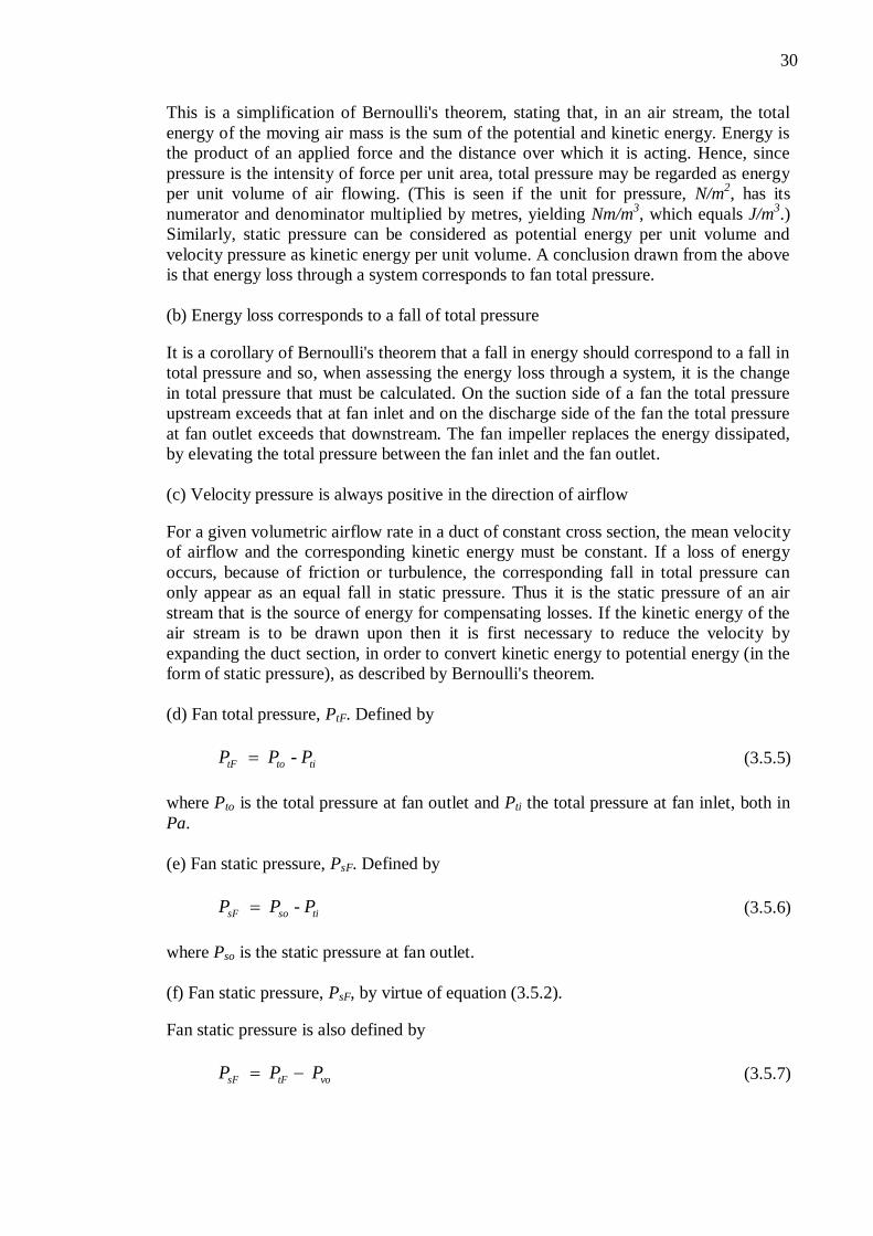
30
This is a simplification of Bernoulli's theorem, stating that, in an air stream, the total
energy of the moving air mass is the sum of the potential and kinetic energy. Energy is
the product of an applied force and the distance over which it is acting. Hence, since
pressure is the intensity of force per unit area, total pressure may be regarded as energy
per unit volume of air flowing. (This is seen if the unit for pressure, N/m2, has its
numerator and denominator multiplied by metres, yielding Nm/m3, which equals J/m
3.)
Similarly, static pressure can be considered as potential energy per unit volume and
velocity pressure as kinetic energy per unit volume. A conclusion drawn from the above
is that energy loss through a system corresponds to fan total pressure.
(b) Energy loss corresponds to a fall of total pressure
It is a corollary of Bernoulli's theorem that a fall in energy should correspond to a fall in
total pressure and so, when assessing the energy loss through a system, it is the change
in total pressure that must be calculated. On the suction side of a fan the total pressure
upstream exceeds that at fan inlet and on the discharge side of the fan the total pressure
at fan outlet exceeds that downstream. The fan impeller replaces the energy dissipated,
by elevating the total pressure between the fan inlet and the fan outlet.
(c) Velocity pressure is always positive in the direction of airflow
For a given volumetric airflow rate in a duct of constant cross section, the mean velocity
of airflow and the corresponding kinetic energy must be constant. If a loss of energy
occurs, because of friction or turbulence, the corresponding fall in total pressure can
only appear as an equal fall in static pressure. Thus it is the static pressure of an air
stream that is the source of energy for compensating losses. If the kinetic energy of the
air stream is to be drawn upon then it is first necessary to reduce the velocity by
expanding the duct section, in order to convert kinetic energy to potential energy (in the
form of static pressure), as described by Bernoulli's theorem.
(d) Fan total pressure, PtF. Defined by
titotF - P P P (3.5.5)
where Pto is the total pressure at fan outlet and Pti the total pressure at fan inlet, both in
Pa.
(e) Fan static pressure, PsF. Defined by
tisosF - P P P (3.5.6)
where Pso is the static pressure at fan outlet.
(f) Fan static pressure, PsF, by virtue of equation (3.5.2).
Fan static pressure is also defined by
votFsF P P P (3.5.7)
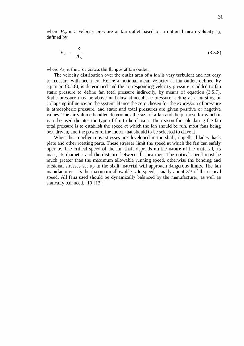
31
where Pvo is a velocity pressure at fan outlet based on a notional mean velocity vfo
defined by
fo
foA
v v
(3.5.8)
where Afo is the area across the flanges at fan outlet.
The velocity distribution over the outlet area of a fan is very turbulent and not easy
to measure with accuracy. Hence a notional mean velocity at fan outlet, defined by
equation (3.5.8), is determined and the corresponding velocity pressure is added to fan
static pressure to define fan total pressure indirectly, by means of equation (3.5.7).
Static pressure may be above or below atmospheric pressure, acting as a bursting or
collapsing influence on the system. Hence the zero chosen for the expression of pressure
is atmospheric pressure, and static and total pressures are given positive or negative
values. The air volume handled determines the size of a fan and the purpose for which it
is to be used dictates the type of fan to be chosen. The reason for calculating the fan
total pressure is to establish the speed at which the fan should be run, most fans being
belt-driven, and the power of the motor that should to be selected to drive it.
When the impeller runs, stresses are developed in the shaft, impeller blades, back
plate and other rotating parts. These stresses limit the speed at which the fan can safely
operate. The critical speed of the fan shaft depends on the nature of the material, its
mass, its diameter and the distance between the bearings. The critical speed must be
much greater than the maximum allowable running speed, otherwise the bending and
torsional stresses set up in the shaft material will approach dangerous limits. The fan
manufacturer sets the maximum allowable safe speed, usually about 2/3 of the critical
speed. All fans used should be dynamically balanced by the manufacturer, as well as
statically balanced. [10][13]
32
4 CALCULATION TOOL
This chapter deals with the operation of the calculation tool and has been prepared to
serve as a guide for the users. The calculation tool consists of these following tabs:
FCU, Fan, Coil, Prints, Main, and Charts. They each have their own rationales, which
have been explained in this chapter.
4.1 General information
Some of the general considerations for calculation tool are listed in the following:
- All light-yellow painted cells are convertible by user
- All option buttons, as well as drop-down lists and command buttons, are
available for use.
- All red painted cells, which may occur somewhere in the tool, means either,
invalid input or any other kind of error situation. Red color in cells is due to the
conditional formatting. In all error cases, at least one error message should be
shown in the Fault –section in FCU –tab.
Any of the other cells and contents of the tool, except those mentioned above, are
protected to avoid any kind of inadvertent use.
4.1.1 Getting started
First of all, when opening the workbook FCU calculation tool, program will ask from
user to disable or enable macros, it is recommended to answer affirmatively (enable
macros), because some of the parts of the tool need macros for full functionality. After
selection, the tool should be open in the main view (FCU –tab).
4.1.2 Conditional formatting
Calculation tool contains a lot of the cells that are conditionally shaped. In this tool,
conditional formatting has been used to express invalid inputs or any other kind of error
situations. Formatting has also been used to change background colour in different
cases, for example when cooling mode is changed to the heating mode.
In calculation tool, conditional formatting can be found under the Format -command
on the menu bar, Format → Conditional Formatting. However, this function cannot be
used when the active cell(s) is protected. Sheet protection can also be found from menu
bar, by choosing Tools → Protection.
33
4.1.3 VBA -macros
This calculation tool also contains several VBA (Visual Basic for Applications) -
macros, which have been prepared to speed up the use of the tool. All of the macro -
codes are listed in the appendices at the end of the thesis.
In calculation tool, macros are found under the Tools -command on the menu bar,
Tools → Macro → Macros.
4.2 FCU -tab
The first tab (FCU) contains main properties of all components of Fan Coil Unit.
Layout of FCU –tab can be seen in Figures 4.1 and 4.2. Figure 4.1 has been taken from
the left side of page, and Figure 4.2 from right side of page. FCU -tab has been divided
into 13 different sections, which are also numbered from 1 to 13 in Figures 4.1 and 4.2.
These sections are:
1. Mode selection
2. Supply air state
3. Capacities
4. Air pressures
5. Filter section
6. Defaults
7. Primary air state
8. Circulated air state
9. Listed faults
10. Electric heater section
11. Fan section
12. Water valve
13. Coil Section
4.2.1 Mode selection and supply air state
These sections are numbered 1 and 2 in the Figure 4.1. At first, the user will have to
choose a mode of use (1), cooling or heating. The cooling mode is used in summer time,
when cooling is needed against heat gains like solar radiation and heat from the
passengers. The heating mode is for winter conditions. Sometimes when the cooling
mode is used, both cooling and heating may be needed in order to dehumidify the cabin
air. This is possible by heating cooled air with the electric heater.
The circumstances of supply air can be followed in section Supply air to cabin (2).
These circumstances are the temperature Tsupply, the humidity RH%supply and the flow
rate Vsupply. Supply air is composed of primary and circulated air, which are sometimes
called fresh and secondary air.

34
Figure 4.1. Layout from the left side of FCU-tab.
4.2.2 Capacities and air pressures
All Fan Coil Unit capacities can be seen in section Capacities (3). The program
calculates all the other capacities except total sensible capacity, which has to be adjusted
by the user. A tool will give the following information based on total demanded sensible
capacity:
- Sensible capacities (primary air, fan, coil)
- Total capacity of refrigerant (water)
- Total capacity of Fan Coil Unit
Air pressures -section (4), contains all details about circulated air pressures in different
parts of Fan Coil Unit. Only approximated pressure drops of inlet and outlet ducts in
Fan Coil Unit have to be adjusted. The tool calculates all the rest of pressures based on
former references. All the calculated pressures are listed in the following:
- Supply available
This pressure equals the pressure between FCU –outlet ducts and cabin free
air. Further this means that the pressure should be high enough to distribute
treated air uniformly into the cabin.
35
- Δpoutlet
This parameter describes pressure drop in outlet ducts, located after the
electric heater. Circulated air has combined with primary air in this section.
- Δpelectric heater
This is the pressure drop through the electric heater section. Usually this can
be noted to be insignificant (less than 5 Pa).
- Δpfan
This parameter describes a pressure change (rise) in the fan section. The fan
must build up the pressure at least an equal amount of the total pressure drop
of all components in Fan Coil Unit. Pressure change during fan section is
usually 150-250 Pa.
- Δpcoil
Pressure drop through coil section is around 20 Pa in normal use.
- Δpdrip pan
Pressure drop in the drip pan is usually around 20 Pa.
- Δpfilter
Pressure drop in filter -section is highly depended on current filter class, and
type (see section 4.2.3). In filter section, the pressure drop with M6 -filter
could rise up to 100 Pa.
- Circulated air pressure
This pressure equals the pressure between FCU inlet and cabin free air. This
pressure should be less than atmospheric static pressure.
- Δptotal
Total pressure drop through Fan Coil Unit. It usually varies between 150 and
250 Pa.
4.2.3 Filter section and default settings
Filter section (5) is for determining filter properties. These properties are classification,
purity and filter size.
Classification has been divided into three different filters, coarse dust filter G3 and
fine dust filters M5 and M6. Loss of pressure is smallest when using coarse dust filter
G3. However, it is seldomly used because of increased requirements of cabin air quality.
Nowadays, commonly used filters are M5 and even M6. The pressure drops of different
filter classes have been studied. It was found that the pressure drops in fine dust filters
M5 and M6 are approximately 70 % and 80 % higher than in coarse dust filter G3.
Obviously the pressure drop in a filter increases quickly with raised airflow rate,
causing higher capacity requirements for fan section.
Selection of purity should be done according to the moment when the filter was
cleaned or changed. If the filter is brand new, selection should be “Clean”, if the filter
has been in use for just a short time, selection could be “25 % dirty”, and so on. This

36
option has been integrated to the tool, because dirtiness affects the pressure drop
strongly.
Filter size also affects to the pressure drop, because it will determine flow velocity
of air. User could manually set the size of filter (in millimetres) by scroll bars.
Default buttons (6) are made for avoiding wrong value inputs and other mistakes,
and for helping the user generally. There are four different sectional default buttons and
one button that resets all inputs.
The first button (Coil) is for resetting all inputs which have been preset to coil
section (number 13 in Figure 4.2).
The second button (Fan, Air pressures and Filter) is for resetting all these following
sections: Air pressures (number 4 in Figure 4.1), filter (number 5 in Figure 4.1) and fan
(number 11 in Figure 4.2).
The third button is for water valve and it will reset all settings in water valve section
(number 12 in Figure 4.2).
The fourth button is for primary air, circulated air and demanded sensible capacity
and it will reset all settings which have been preset to these mentioned sections
(numbers 3, 7 and 8 in Figure 4.1).
The last button collects all of the four buttons mentioned above and resets all inputs.
It is recommended to use this button always before using the tool for eliminating all
incorrect settings which have possibly been left in the program.
4.2.4 Primary and circulated air states
Primary air -section (7) has been made for adjusting the state of primary air. The user
can switch primary air on/off by option button located in the right top corner of the box.
The colour of the box is white when primary air is turned “off”, and green when turned
“on”. Adjustable quantities are temperature in Celsius, °C, humidity in per cent, %, and
flow rate in cubic meters per hour, m3/h or cubic decimetres per second, dm
3/s. Scroll
bar must be used to make these adjustments.
Circulated air control box (8) operates exactly as the primary air control box with
one exception: circulated air does not have on/off -option button. It’s also good to
remember that circulated air state is equivalent with cabin air state.
4.2.5 Listed faults
Listed faults -section (9) gives information for the user if settings are indeterminable or
if there is any kind of inconsistency between inputs (for example, capacity demand is
too high). Program will always print at least one fault message to the screen if any kind
of error establishes. Texts of faults are always red bolded as well as all errors in any
other part of the tool. All faults and possible reasons of occurring are listed here:
- WATER INLET TEMPERATURE IS TOO HIGH
This fault occurs only in cooling mode when inlet water temperature
exceeds circulated air temperature after coil, which is determined by
demanded capacity of Fan Coil Unit.
- WATER OUTLET TEMPERATURE IS TOO HIGH

37
Occurs only in cooling mode when outlet water temperature has been set
to be more than circulated air temperature after coil.
- WATER OUTLET TEMPERATURE IS TOO LOW
Occurs only in heating mode when outlet water temperature is less than
demanded circulated air temperature after coil.
- FLOW RATE OF PRIMARY AIR IS HIGHER THAN RECOMMENDED
FOR TWO PERSONS
Occurs when primary air flow rate has been set to be more than 150 m3/h
(~42 dm3/s)
- STATIC PRESSURE OF SUPPLY AIR IS TOO LOW!
Occurs when pressure "supply available" does not exceed static cabin air
pressure.
- STATIC PRESSURE OF INLET AIR IS TOO MUCH!
Occurs when pressure "circulated air pressure" is less than static cabin air
pressure.
- AIR FLOW RATE WITH CURRENT AIR PRESSURE DROP IS TOO MUCH
FOR CURRENT FAN
Occurs when fan performance is not enough for combination of
circulated air flow rate and pressure drop in FCU.
- WATER TEMPIN MUST BE LESS THAN WATER TEMPOUT IN COOLING
MODE!
Occurs in cooling mode when inlet water temperature is higher or equal
with outlet water temperature.
- WATER TEMPIN SHOULD BE MORE THAN WATER TEMPOUT IN
HEATING MODE!
Occurs in heating mode when inlet water temperature is lower or equal
with outlet water temperature.
- TABLE OF ACTIVE FAN IN “FAN” -SHEET CONTAINS INVALID
INPUTS!
Occurs when invalid input(s) have been fed and saved into the fan tables
and this same fan has selected to be active fan. In this case, all fan data
must to be removed and saved again with correct inputs to remove this
incorrect input(s).
- TABLE OF ACTIVE COIL IN “COIL” -SHEET CONTAINS INVALID
INPUTS!
This fault occurs instantly when invalid input(s) have been fed to the coil
tables in "Coil" -sheet. Incorrect cells are shown by red painted colour
and these cells are possible to repair one at time.
- CURRENT MAXIMUM SENSIBLE CAPACITY OF FCU HAS EXCEEDED

38
Occurs when demanded FCU -capacity exceeds a current available
maximum capacity. Available maximum capacity depends highly from
circulated air flow rate.
- CIRCULATED AIR TEMPERATURE AFTER COIL PREFER TO BE MORE
THAN DEW POINT OF CABIN AIR
Occurs when demanded circulated air temperature after coil is less than
dew point of cabin. This situation is unfavourable because condensing
rate of water starts rising.
- TEMPERATURE DIFFERENCE BETWEEN ROOM AND SUPPLY AIR
PREFER TO BE 5-10 DEGREES (°C)
This aim is recommendation and occurs only in cooling mode when
supply air to cabin is not between 5 and 10 degrees below cabin air.
- FLOW RATE AND PRESSURE DROP OF THE WATER IS TOO HIGH
Occurs when water pressure drop exceeds 200 kPa. Pressure drop is
highly depended from water flow rate, which in turn is depended of
water inlet and outlet temperatures.
Figure 4.2. Layout from the right side of FCU-sheet.
39
4.2.6 Electric heater and fan -sections
Electric heater -section (10) is for using electric heater to warm circulated air. It can be
used in heating mode or even cooling mode to dehumidify air when drying cabin air is
needed. The scroll bar is not active before user picks option “on” from right top corner
of the box. Usually there are 400 W and 800 W electric resistances integrated into Fan
Coil Unit, which makes total heating capacity up to 1200 W. The range of heating scroll
bar is as well from 0 to 1200 W.
Fan control box (11) is for the selection of a suitable fan for the unit. There are
preset fans to choose from dropping list. There are nominal values of the active fan
below the drop list. Characteristic curve can be seen in the middle and current
specifications on the right side of the control box (see Figure 4.2). New fans can be
added from Fan –tab if needed (see section 4.3).
4.2.7 Water valve and coil section
Refrigerant details will be determined from water valve -control box (12). An option
button can be found to switch valve “On” or “Off” position. Inlet and outlet water
temperatures are adjustable by the user. These must be adjusted in a way that ensures
the water flow rate and pressure drop of water does not rise too much. The tool
calculates the flow rate and pressure drop of refrigerant automatically.
Coil section (13) is the widest section of this tool. There is a drop down -list for
selecting the coil. All the other coils in the list are preset coils except the first one.
While first one (Adjustable coil) is selected, user may adjust all coil dimensions at will
and search optimal heat transfer properties. The following dimensions of the coil are
adjustable:
- Width, height and depth of coil
- Amount of fins
- Fin thickness
- Amount of tubes per row
- Amount of tube rows
- Tube diameter
Heat transfer properties of coil are highly depended of width, height and depth of coil.
While these dimensions increase, the heat transfer capacity is also increased, because of
larger coil surface area (see equation 3.4.10).
The amount of fins also has a large effect on heat transfer capacities. The reason is
exactly the same as with increased coil dimensions, more surface area means increased
capacity. Increased amount and size of tubes means longer total length of tubes. This
makes it possible to remove more heat capacity from water to air with the same flow
rate.
These additional features are adjustable: Coil material, coil configuration and
correction factor for wet conditions. Two optional coil materials are selectable: copper
(commonly used in Fan Coil Unit) and aluminium. Three different coil configurations
are selectable: counter flow, parallel flow and a mixture of them. Counter flow is
commonly used but the present coil used in Halton is a mixture of counter and parallel
flow. Therefore “mixed” configuration is the most suitable one to use in this tool.
Correction factor for wet conditions may vary from 0.82 to 0.92. However, the effect to

40
capacity errors is negligible so it is recommended to leave this scroll bar to its preset
value 0.87.
4.3 Fan -tab
All fans could be managed from this page. There are three different tables on top of the
sheet (see Figures 4.3 and 4.4) All data tables of saved fans can be found below these
three fan tables. The first table, “Fan input table” is for adding new fans to the tool, and
the second table, “Listed fans“ is for removing old fans from the tool. The third table is
named “Active fan table”, where the details of active fan performance can be seen.
Figure 4.3. Tables “Fan input table” and “Listed fans” on the Fan-sheet.
4.3.1 Adding and removing fans
A new fan can be added by entering all asked mandatory fields (cell range C3:C8 in
Figure 4.3), and optional fields (cell range D9:E28 in Figure 4.3) to the table “Fan input
table”. Charasteristic curve chart was created by studying manufacturer’s fan
performances and entering optional inputs, the air flow rate and corresponding pressures
at least from five different operation points, to the table. The program creates the
characteristic curves based on third-order functions. Lastly, after all this data has been
entered, the fan must be saved by pressing "Save new fan” –button. The program will
inform the user that the fan is saved succesfully by a text window. The fan will appear
to the table "Listed Fans", located below the fan input table. The program also asks if

41
user wants to clear already stored data from the input table for a new fan. The new fan
can be found from the tool and it can be activated from the Fan-section drop-down
menu located in the "FCU" –sheet (see Figure 4.2). The program reports errors if the
user enters incorrect values into the fan input table.
If the table "Listed Fans” is full, meaning that all 15 different fan tables are in use, it
is required to remove some of the older fans from the list before saving new ones.
Removal is done by selecting desired fans from check boxes (cell range I38:I51 in
Figure 4.3), and removing these fans by a button on top of the boxes.
Figure 4.4. Active fan table on the Fan-sheet.
The charasteristic curve chart of the active fan is based on the “Active fan table”.
The maximum pressure drop and sufficiency of the fan in current circulated air flow rate
are shown, if all rows of optional inputs have been entered (see column “U” in Figure
4.4). The third order functions for creating the characteristic curves can also be seen on
this table. It can be concluded that the actual performance curves follow quite closely
the calculated curves, which are based on the third order functions.
Note: It is recommended to save the workbook every time before closing it, if new
fan(s) has been saved.
4.4 Coil -tab
Most of the calculations, which are associated in any way with the coil section, are
located in this page. As told before, table “Coils” (see Figure 4.5) is for managing
cooling coils. Adding or removing coils can be done by using this table.
4.4.1 Adding and removing coils
The cooling coil addition is done by entering input data into yellow painted cells in the
table (see Figure 4.5). The table contains one row for each cooling coil (Cell range
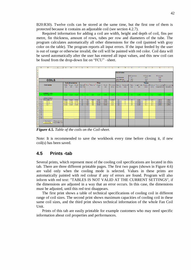
42
B20:R30). Twelve coils can be stored at the same time, but the first one of them is
protected because it contains an adjustable coil (see section 4.2.7).
Required information for adding a coil are width, height and depth of coil, fins per
metre, fin thickness, amount of rows, tubes per row and diameters of the tube. The
program calculates automatically all other dimensions for the coil (painted with gray
color on the table). The program reports all input errors. If the input feeded by the user
is out of range or otherwise invalid, the cell will be painted with red color. Coil data will
be saved automatically after the user has entered all input values, and this new coil can
be found from the drop-down list on “FCU” –sheet.
Figure 4.5. Table of the coils on the Coil-sheet.
Note: It is recommended to save the workbook every time before closing it, if new
coil(s) has been saved.
4.5 Prints -tab
Several prints, which represent most of the cooling coil specifications are located in this
tab. There are three different printable pages. The first two pages (shown in Figure 4.6)
are valid only when the cooling mode is selected. Values in these prints are
automatically painted with red colour if any of errors are found. Program will also
inform with red text: "TABLES IS NOT VALID AT THE CURRENT SETTINGS", if
the dimensions are adjusted in a way that an error occurs. In this case, the dimensions
must be adjusted, until this red text disappears.
The first print shows a table of technical specifications of cooling coil in different
range of coil sizes. The second print shows maximum capacities of cooling coil in these
same coil sizes, and the third print shows technical information of the whole Fan Coil
Unit.
Prints of this tab are easily printable for example customers who may need specific
information about coil properties and performances.

43
Figure 4.6. Current coil properties.
4.5.1 Coil properties
The first print contains all the main parameters of the cooling coil. It is possible to select
four different parameters at the same time from drop-down menus. The table shows the
changes in the results of selected parameters in different coil size options. Bolded values
in the middle of the table represent results of parameters in current settings. Results of
these same parameters are also shown in the table with the following changes in
columns:
- Current, 5 % reduced and 5 % increased amount of fins.
- All above mentioned amounts of fins with 2, 4, and 6 tube rows.
And in rows:
- Current, 10 % reduced and 10 % increased widths of coil.
- All above mentioned widths with current, 10 % reduced and 10 % increased
heights of coil.
The user can easily study how the cooling coil characteristics and capacities behave
with all of these dimension changes mentioned above. Dimensions are easily
changeable with scroll bars in the first print, and therefore there is no need to browse
different tabs for dimension changes. These dimensions will be automatically changed
in FCU –tab also. The next different quantities and properties are selectable from the
drop-down list:
- Air humidity after coil
- Air temperature after coil
44
- Condense water
- Contact factor of coil
- External surface area of all fins
- External surface area of all tubes
- External total surface area
- Face velocity of coil
- Face area of coil
- Fin efficiency
- Logarithmic mean temperature difference between air and mean coil surface
- Logaritmic mean temperature difference between air and water stream
- Ratio of external to internal surface area
- U-value of the coil
- Water flow rate m3/h or dm
3/s
All needed cooling coil capacities are shown in the second print (right side in Figure
4.6). All capacities in the second print will follow dimension changes as well.
4.5.2 Fan Coil Unit specifications
All the most important parameters and specifications of Fan Coil Unit are collected to
the last print and are shown on their own separated sections in the table (see appendix
B.3).
4.6 Main -tab
Most of the general calculations and functions of the program are located in the table on
this tab (table “Fan Coil Unit functions”). Roughly speaking, the structure of the table is
divided so that all different water and air states are located to the rows, and the
corresponding quantities of them to the columns. The only inputs that can be managed
from this sheet are “Total fan efficiency” (located in cell C24), and total outer
dimensions of Fan Coil Unit (cells E35:I35). Anyway, it must be observed that
changing the total fan efficiency has negligible effect on the Fan Coil Unit properties.
Tables of water and dry air properties are also located on this tab. The source for
these tables is the Basic heat and mass transfer by Mills. [3]
4.7 Charts -tab
All graphs of the calculation tool are located on this tab, as well as some of the sources
for them. In the following are listed charts of this sheet:
- Cooling capacities in different cabin temperatures
- Contact factor in different rows in coil
- Circulated air humidity after coil in different cabin humidities
- Function of water flow speed and pressure drop of water
- Pressure drop charts in different Fan Coil Unit components
45
5 CONCLUSIONS
A few difficult calculation problems were revealed during this work, which gave their
own challenges for planning the calculation tool. The biggest problems of all were in
model humidity changes, as well as the amount of condensate water in the coil section.
Especially the latter of those was very hard to model accurately, because there were not
enough reference cases from earlier tests to support these theoretical calculations.
However, this error is not significant when considering the operation of the calculation
tool.
There were also a few problems with linking functions and cells to each other. In the
middle of the project was needed to clarify the calculation tool because it had become
too complex and difficult for further design. The final phase of the project was laborious
and the most time consuming part, because the corrections of the tool operation took
more time than was originally planned.
There are also unwanted features occurring when references are used in calculations
to correct the results. One of those is that when using references for correcting results,
these corrections are not working anymore when significant changes are made to Fan
Coil Unit, for example when changing a totally different type of coil section to Unit.
Overall, the work was a success, although some of the originally planned features
are still missing because of limited time. One of the missing features is the calculation
of costs. On the other hand, the calculation tool includes some extra features that were
not originally planned for the tool. The possibilities provided by the calculation tool will
bring a lot of savings in time and in resources.
The calculation tool has been tested many times by comparing its results with earlier
reference results obtained from previous measurements, and it can be concluded that the
calculated results have been very close to the reference results.
In future, the calculation tool can be easily extended in many directions. For
example, it might be useful property if the tool would consider all outer dimension
changes of Fan Coil Unit and give an alert to the user if the outer shell of Unit is too
small for fitting the needed Unit components. It would also be useful to integrate the
calculation tool with cabin drawings and cabins heat load calculations, and of course,
the tool should warn the user as well if Unit is too small for needed cabin size and
cabins heat loads.

46
REFERENCES
[1] ARI 410 (1991). Forced-circulation Air-cooling and Air-heating coils, Air-
conditioning and Refrigeration Institute, Arlington, VA.
[2] ASHRAE Handbook (1996). Heating, Ventilating and Air Conditioning
Systems and Equipment, ASHRAE.
[3] Mills A.F. (1999). Basic heat and mass transfer, 2nd edition, Prentice Hall.
[4] Perry, R.H. and Green, D.W. (1997). Perry's Chemical Engineers' Handbook,
7th edition, McGraw-Hill.
[5] Dew Point, Wikipedia (2012). [WWW]. [Referred 9.5.2012]. Available:
http://en.wikipedia.org/wiki/Dew_point.
[6] Fan Coil Unit, Wikipedia (2012). [WWW]. [Referred 9.1.2012]. Available:
http://en.wikipedia.org/wiki/Fan_coil_unit.
[7] Berglund, L. (1998). “Comfort and Humidity”, ASHRAE Journal, August
1998.
[8] McAdams, W.H. (1954). Heat transmission, 3rd edition, McGraw-Hill Book
Company, New York.
[9] Schmidt, T.E. (1945). La production calorifique des surfaces munies d’ailettes,
Bulletin de l’Institut International du Froid, Annexe G-5.
[10] Jones, W. P. (2001). Air Conditioning Engineering, 5th edition, Butterworth-
Heinemann.
[11] Halton intranet (2011). [WWW].
[12] ASHRAE (2001). Fundamentals Handbook, ASHRAE.
[13] ASHRAE (1993). Handbook of Fundamentals. American Society of
Refrigeration and Air-Conditioning Engineers Inc. Atlanta, GA.
[14] Berkeley, L. (2012). National Laboratory Washington, DC. Resource
Dynamics Corporation Vienna, VA. [WWW]. [Referred 4.3.2012]. Available:
http://www1.eere.energy.gov/manufacturing/tech_deployment/pdfs/fan_sourc
ebook.pdf.
[15] Wang, S.K. and Lavan, Z. (1999). Air-Conditioning and Refrigeration,
Mechanical Engineering Handbook, Boca Raton: CRC Press LLC.
[16] Air Conditioning (2012). [WWW]. [Referred 18.2.2012]. Available:
http://www.thermopedia.com/content/550/

47
APPENDICES
A.1. Exploded view of Fan Coil Unit –components
B.1. Print, coil properties 1/2
B.2. Print, coil properties 2/2
B.3. Print, current FCU -specifications
C.1. VBA Macro codes: Fan_add
C.2. VBA Macro codes: Fan_remove
C.3. VBA Macro codes: CroppingSheets, Prim_air_Cir_air_capacities,
Fan_air_pressures_filter, Water_valve
C.4. VBA Macro codes: Coil, All

48
APPENDIX A: EXPLODED VIEW OF FAN COIL UNIT
Figure A.1. FCU –components in exploded view.

49
APPENDIX B: PRINTS OF THE TOOL
Figure B.1. Print, coil properties 1/2.
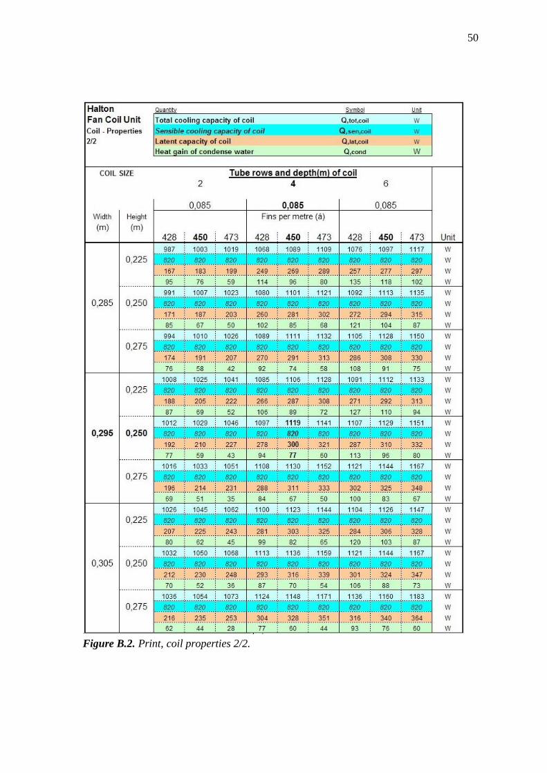
50
Figure B.2. Print, coil properties 2/2.

51
Figure B.3. Print, current FCU –specifications.

52
APPENDIX C: VBA-MACRO CODES
' Fan_add Macro
' Macro recorded 8.11.2011 by Hakala
Sub Fan_add()
Name = Range("C3")
Power = Range("C4") Speed = Range("C5")
Freq = Range("C6")
Inlet = Range("C7")
Flow = Range("C8")
If IsEmpty(Name) Then
MsgBox "Fan model name required"
Range("C3").Select
Exit Sub
ElseIf IsEmpty(Power) Then
MsgBox "Fan maximum power is
required" Range("C4").Select
Exit Sub
ElseIf Power < 1 Or Power > 300 Then
MsgBox "Invalid maximum fan power"
Range("C4").Select
Exit Sub
ElseIf IsEmpty(Speed) Then
MsgBox "Maximum fan speed is
required"
Range("C5").Select
Exit Sub
ElseIf Speed < 0 Or Speed > 5000 Then MsgBox "Invalid maximum fan speed"
Range("C5").Select
Exit Sub
ElseIf Freq <> 50 And Freq <> 60 Then
MsgBox "Invalid Frequency, valid
frequencys: 50 or 60"
Range("C6").Select
Exit Sub
ElseIf Inlet <> 1 And Inlet <> 2 Then
MsgBox "Invalid amount of inlets, valid
inlets: 1 or 2" Range("C7").Select
Exit Sub
ElseIf Flow <= 0 Or Flow > 999 Then
MsgBox "Invalid maximum flow rate, set
value between 1 and 999"
Range("C8").Select
Exit Sub
Else
Dim Answer As Integer
Answer = MsgBox(prompt:="Are you
sure you want to save a new fan?", _
Buttons:=vbYesNo + vbQuestion, Title:="Fan saving")
If Answer = vbYes Then
Range("D9:E28").Select
Selection.Copy
ActiveSheet.Range("C63").End(xlDown).Offs
et(6, 1).Select
Selection.PasteSpecial
Paste:=xlValues, Operation:=xlNone, SkipBlanks:= _
False, Transpose:=False
Range("C3:C7").Select
Selection.Copy
ActiveSheet.Range("C63").End(xlDown).Offs
et(1, 0).Select
Selection.PasteSpecial
Paste:=xlValues, Operation:=xlNone,
SkipBlanks:= _
False, Transpose:=False
Range("A1").Select Selection.ClearContents
Dim Answer2 As Integer
Answer2 = MsgBox(prompt:="Fan is
now added and will be found from fan
dropping list.
Do you want also clear input data
table for a next fan? ", _
Buttons:=vbYesNo + vbQuestion,
Title:="Note")
If Answer2 = vbYes Then
Range("C3:C8").Select
Selection.ClearContents Range("D10:E28").Select
Selection.ClearContents
Range("C3").Select
ActiveCell.FormulaR1C1 = "Fan
name"
Range("A1").Select
Selection.ClearContents
Else
Range("A1").Select
Selection.ClearContents
End If Else
End If
End If
End Sub
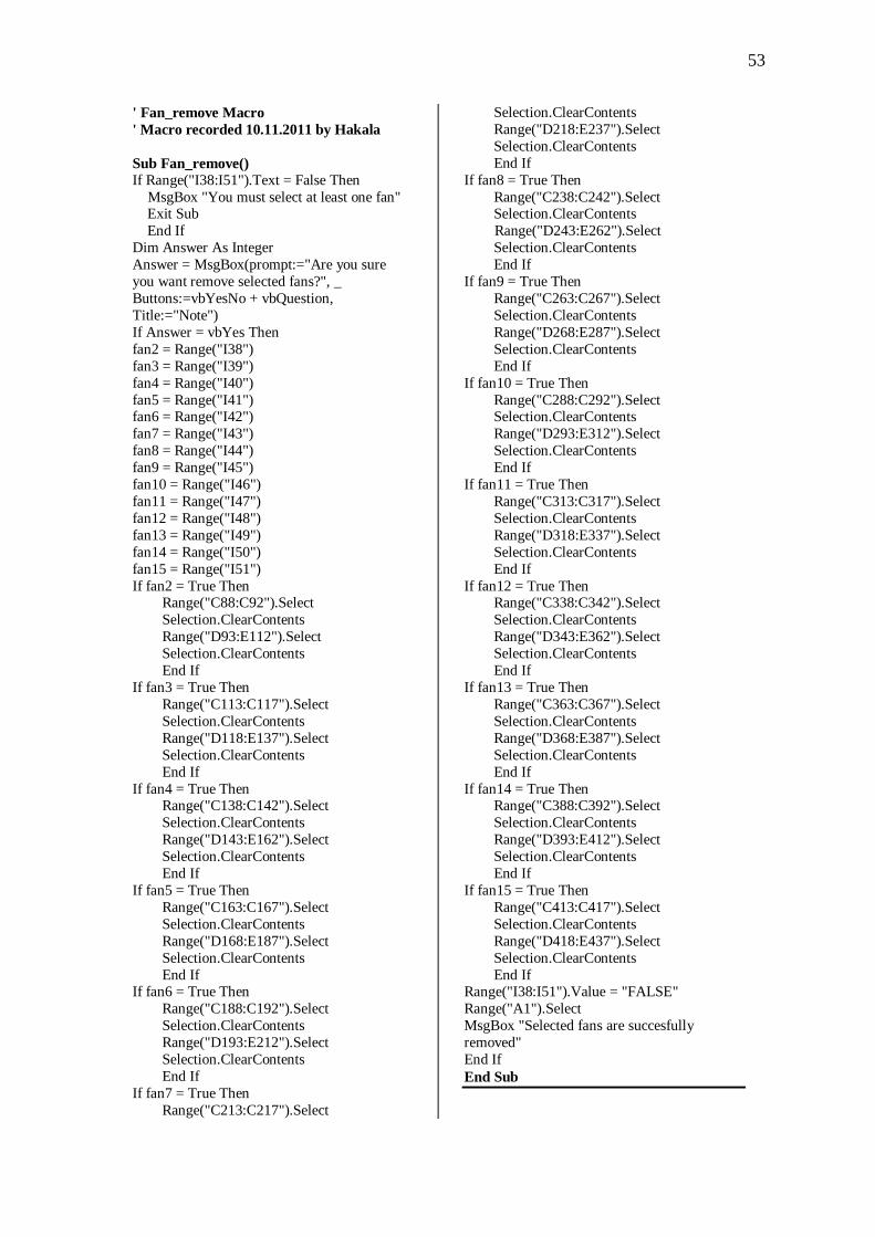
53
' Fan_remove Macro
' Macro recorded 10.11.2011 by Hakala
Sub Fan_remove() If Range("I38:I51").Text = False Then
MsgBox "You must select at least one fan" Exit Sub
End If
Dim Answer As Integer
Answer = MsgBox(prompt:="Are you sure
you want remove selected fans?", _
Buttons:=vbYesNo + vbQuestion,
Title:="Note")
If Answer = vbYes Then
fan2 = Range("I38")
fan3 = Range("I39")
fan4 = Range("I40")
fan5 = Range("I41") fan6 = Range("I42")
fan7 = Range("I43")
fan8 = Range("I44")
fan9 = Range("I45")
fan10 = Range("I46")
fan11 = Range("I47")
fan12 = Range("I48")
fan13 = Range("I49")
fan14 = Range("I50")
fan15 = Range("I51")
If fan2 = True Then Range("C88:C92").Select
Selection.ClearContents
Range("D93:E112").Select
Selection.ClearContents
End If
If fan3 = True Then
Range("C113:C117").Select
Selection.ClearContents
Range("D118:E137").Select
Selection.ClearContents
End If
If fan4 = True Then Range("C138:C142").Select
Selection.ClearContents
Range("D143:E162").Select
Selection.ClearContents
End If
If fan5 = True Then
Range("C163:C167").Select
Selection.ClearContents
Range("D168:E187").Select
Selection.ClearContents
End If If fan6 = True Then
Range("C188:C192").Select
Selection.ClearContents
Range("D193:E212").Select
Selection.ClearContents
End If
If fan7 = True Then
Range("C213:C217").Select
Selection.ClearContents
Range("D218:E237").Select
Selection.ClearContents
End If
If fan8 = True Then
Range("C238:C242").Select Selection.ClearContents
Range("D243:E262").Select
Selection.ClearContents
End If
If fan9 = True Then
Range("C263:C267").Select
Selection.ClearContents
Range("D268:E287").Select
Selection.ClearContents
End If
If fan10 = True Then
Range("C288:C292").Select Selection.ClearContents
Range("D293:E312").Select
Selection.ClearContents
End If
If fan11 = True Then
Range("C313:C317").Select
Selection.ClearContents
Range("D318:E337").Select
Selection.ClearContents
End If
If fan12 = True Then Range("C338:C342").Select
Selection.ClearContents
Range("D343:E362").Select
Selection.ClearContents
End If
If fan13 = True Then
Range("C363:C367").Select
Selection.ClearContents
Range("D368:E387").Select
Selection.ClearContents
End If
If fan14 = True Then Range("C388:C392").Select
Selection.ClearContents
Range("D393:E412").Select
Selection.ClearContents
End If
If fan15 = True Then
Range("C413:C417").Select
Selection.ClearContents
Range("D418:E437").Select
Selection.ClearContents
End If Range("I38:I51").Value = "FALSE"
Range("A1").Select
MsgBox "Selected fans are succesfully
removed"
End If
End Sub
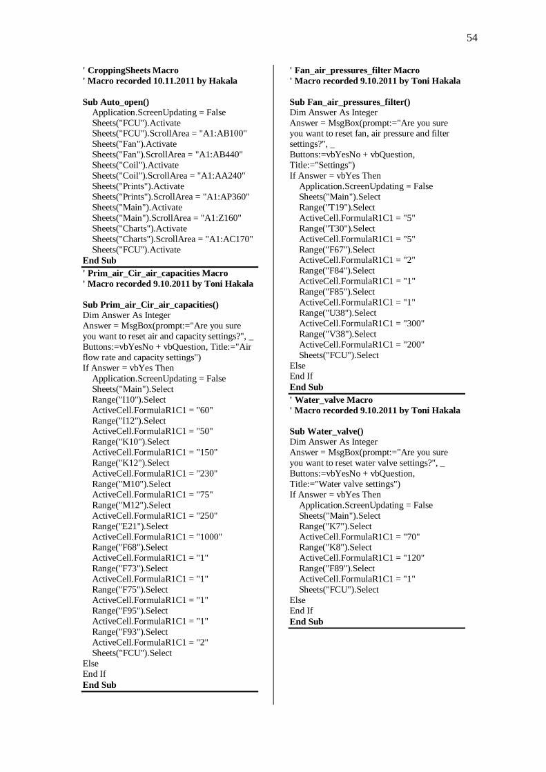
54
' CroppingSheets Macro
' Macro recorded 10.11.2011 by Hakala
Sub Auto_open() Application.ScreenUpdating = False
Sheets("FCU").Activate Sheets("FCU").ScrollArea = "A1:AB100"
Sheets("Fan").Activate
Sheets("Fan").ScrollArea = "A1:AB440"
Sheets("Coil").Activate
Sheets("Coil").ScrollArea = "A1:AA240"
Sheets("Prints").Activate
Sheets("Prints").ScrollArea = "A1:AP360"
Sheets("Main").Activate
Sheets("Main").ScrollArea = "A1:Z160"
Sheets("Charts").Activate
Sheets("Charts").ScrollArea = "A1:AC170"
Sheets("FCU").Activate
End Sub
' Prim_air_Cir_air_capacities Macro
' Macro recorded 9.10.2011 by Toni Hakala
Sub Prim_air_Cir_air_capacities() Dim Answer As Integer
Answer = MsgBox(prompt:="Are you sure
you want to reset air and capacity settings?", _
Buttons:=vbYesNo + vbQuestion, Title:="Air
flow rate and capacity settings")
If Answer = vbYes Then
Application.ScreenUpdating = False
Sheets("Main").Select
Range("I10").Select
ActiveCell.FormulaR1C1 = "60"
Range("I12").Select ActiveCell.FormulaR1C1 = "50"
Range("K10").Select
ActiveCell.FormulaR1C1 = "150"
Range("K12").Select
ActiveCell.FormulaR1C1 = "230"
Range("M10").Select
ActiveCell.FormulaR1C1 = "75"
Range("M12").Select
ActiveCell.FormulaR1C1 = "250"
Range("E21").Select
ActiveCell.FormulaR1C1 = "1000" Range("F68").Select
ActiveCell.FormulaR1C1 = "1"
Range("F73").Select
ActiveCell.FormulaR1C1 = "1"
Range("F75").Select
ActiveCell.FormulaR1C1 = "1"
Range("F95").Select
ActiveCell.FormulaR1C1 = "1"
Range("F93").Select
ActiveCell.FormulaR1C1 = "2"
Sheets("FCU").Select
Else End If
End Sub
' Fan_air_pressures_filter Macro
' Macro recorded 9.10.2011 by Toni Hakala
Sub Fan_air_pressures_filter() Dim Answer As Integer
Answer = MsgBox(prompt:="Are you sure you want to reset fan, air pressure and filter
settings?", _
Buttons:=vbYesNo + vbQuestion,
Title:="Settings")
If Answer = vbYes Then
Application.ScreenUpdating = False
Sheets("Main").Select
Range("T19").Select
ActiveCell.FormulaR1C1 = "5"
Range("T30").Select
ActiveCell.FormulaR1C1 = "5"
Range("F67").Select ActiveCell.FormulaR1C1 = "2"
Range("F84").Select
ActiveCell.FormulaR1C1 = "1"
Range("F85").Select
ActiveCell.FormulaR1C1 = "1"
Range("U38").Select
ActiveCell.FormulaR1C1 = "300"
Range("V38").Select
ActiveCell.FormulaR1C1 = "200"
Sheets("FCU").Select
Else End If
End Sub
' Water_valve Macro
' Macro recorded 9.10.2011 by Toni Hakala
Sub Water_valve() Dim Answer As Integer Answer = MsgBox(prompt:="Are you sure
you want to reset water valve settings?", _
Buttons:=vbYesNo + vbQuestion,
Title:="Water valve settings")
If Answer = vbYes Then
Application.ScreenUpdating = False
Sheets("Main").Select
Range("K7").Select
ActiveCell.FormulaR1C1 = "70" Range("K8").Select
ActiveCell.FormulaR1C1 = "120"
Range("F89").Select
ActiveCell.FormulaR1C1 = "1"
Sheets("FCU").Select
Else
End If
End Sub

55
' Coil Macro
' Macro recorded 9.10.2011 by Toni Hakala
Sub Coil() Dim Answer As Integer
Answer = MsgBox(prompt:="Are you sure you want to reset coil settings?", _
Buttons:=vbYesNo + vbQuestion, Title:="Coil
settings")
If Answer = vbYes Then
Application.ScreenUpdating = False
Sheets("Main").Select
Range("E34").Select
ActiveCell.FormulaR1C1 = "85"
Range("G34").Select
ActiveCell.FormulaR1C1 = "250"
Range("I34").Select
ActiveCell.FormulaR1C1 = "295" Range("L34").Select
ActiveCell.FormulaR1C1 = "4"
Range("N34").Select
ActiveCell.FormulaR1C1 = "10"
Range("P34").Select
ActiveCell.FormulaR1C1 = "450"
Range("S34").Select
ActiveCell.FormulaR1C1 = "20"
Sheets("Coil").Select
Range("A13").Select
ActiveCell.FormulaR1C1 = "1" Sheets("FCU").Select
Else
End If
End Sub
' All Macro
' Macro recorded 2.12.2011 by Toni Hakala
Sub All() Dim Answer As Integer
Answer = MsgBox(prompt:="Are you sure
you want to reset all FCU settings?", _
Buttons:=vbYesNo + vbQuestion, Title:="FCU settings")
If Answer = vbYes Then
Application.ScreenUpdating = False
Sheets("Main").Select
Range("K7").Select
ActiveCell.FormulaR1C1 = "70"
Range("K8").Select
ActiveCell.FormulaR1C1 = "120"
Range("I10").Select
ActiveCell.FormulaR1C1 = "60"
Range("I12").Select ActiveCell.FormulaR1C1 = "50"
Range("K10").Select
ActiveCell.FormulaR1C1 = "150"
Range("K12").Select
ActiveCell.FormulaR1C1 = "230"
Range("M10").Select
ActiveCell.FormulaR1C1 = "75"
Range("M12").Select
ActiveCell.FormulaR1C1 = "250"
Range("T19").Select
ActiveCell.FormulaR1C1 = "5"
Range("T30").Select
ActiveCell.FormulaR1C1 = "5"
Range("E20").Select ActiveCell.FormulaR1C1 = "400"
Range("E21").Select
ActiveCell.FormulaR1C1 = "1000"
Range("E34").Select
ActiveCell.FormulaR1C1 = "85"
Range("G34").Select
ActiveCell.FormulaR1C1 = "250"
Range("I34").Select
ActiveCell.FormulaR1C1 = "295"
Range("L34").Select
ActiveCell.FormulaR1C1 = "4"
Range("N34").Select ActiveCell.FormulaR1C1 = "10"
Range("P34").Select
ActiveCell.FormulaR1C1 = "450"
Range("S34").Select
ActiveCell.FormulaR1C1 = "20"
Range("X34").Select
ActiveCell.FormulaR1C1 = "94"
Range("D36").Select
ActiveCell.FormulaR1C1 = "87"
Range("C37").Select
ActiveCell.FormulaR1C1 = "3" Range("U38").Select
ActiveCell.FormulaR1C1 = "300"
Range("V38").Select
ActiveCell.FormulaR1C1 = "200"
Range("F67").Select
ActiveCell.FormulaR1C1 = "2"
Range("F68").Select
ActiveCell.FormulaR1C1 = "1"
Range("F73").Select
ActiveCell.FormulaR1C1 = "1"
Range("F75").Select
ActiveCell.FormulaR1C1 = "1" Range("F84").Select
ActiveCell.FormulaR1C1 = "1"
Range("F85").Select
ActiveCell.FormulaR1C1 = "1"
Range("F89").Select
ActiveCell.FormulaR1C1 = "1"
Range("F90").Select
ActiveCell.FormulaR1C1 = "1"
Range("F92").Select
ActiveCell.FormulaR1C1 = "1"
Range("F93").Select ActiveCell.FormulaR1C1 = "2"
Range("F95").Select
ActiveCell.FormulaR1C1 = "1"
Sheets("FCU").Select
Range("A1").Select
Else
End If
End Sub