Embed Size (px)
Citation preview

TOMELLERI ENGINEERING MEASURING MACHINES
_______________________________________________________________________________________________________
Viale del Lavoro 12/a - I-37069 VILLAFRANCA (VR) - Tel +39.045.630.47.44 - Fax +39.045.630.36.57 www.tomelleri-spacearms.com
TOMELLERI ENGINEERING S.r.l. Legal Office:
Viale del Lavoro 12/A 37069 VILLAFRANCA (VR) ITALY Via Orione 6 37066 SOMMACAMPAGNA (VR) ITALY
Phone +39.045.6304744 Fax. +39.045.6303657 Phone +39.045.8961420 Fax. +39.045.8979782
E-mail: [email protected] P.IVA: 01664120233
Pagina 1 di 19
PORTABLE MEASURING MACHINE SPACE
User manual.
Rev.: Mspl_07
MACHINE DATA
Machine Portable measuring machine
Model SPACE
Power supply 100 - 240V / 50 Hz - 60 Hz
Protection IP 54
Operating conditions
+10° to +40°, Humidity 90% without
condensing Each measuring machine is certified following the ISO 10360-2 procedure.
TOMELLERI ENGINEERING
Pagina 2 di 19
Copyright Tomelleri Engineering S.r.l. 2016 Aknowledgements:.. ............This documentation may refer to some trademarks, Microsoft® and
Windows® are registered trademarks of Microsoft Corporation in the United States and other countries. Renishaw® is a registered trademark of Renishaw plc.
All right reserved:.................No part of this document may be photocopied, reproduced, or translated
into another language without the prior written consent to Tomelleri Engineering S.r.l.
Warning:..............................The informations contained in this document are subject to change
without notice, Tomelleri Engineering S.r.l. reserves this right to improve over time the specifics of the technical documentation provided to the user.
Note:....................................The technical characteristics of the machine should not be considered
binding, we reserve the right to make changes to improve product quality and technical performance.
Attention:......................... Before you move, install, start, operate and dismantle the machine, you must have understood and have followed the conditions specified in the various chapters of this documentation. Any indication that was not followed or understood, in case of malfunction or damage to persons or property not involves the direct responsibility of the manufacturer.

TOMELLERI ENGINEERING
Pagina 3 di 19
INDEX
1.0 introduction................................................................................................................. 4
1.1 generality.................................................................................................................... 4
1.2 warranty...................................................................................................................... 4
1.3 CE compliant.............................................................................................................. 5
1.4 machine and accessories........................................................................................... 5
1.5 identify plate ............................................................................................................... 10
1.6 important advice......................................................................................................... 11
1.7 information about security and use…………...…........................................................ 12
1.8 transport ..................................................................................................................... 13
1.9 setting up…………...................................................................................................... 13
2.0 mounting and dismounting of the probes.................................................................... 16
2.1 control buttons……..................................................................................................... 17
2.2 electromagnetic brake (if present) and rest position …………................................... 17
2.3 troubleshooting…….................................................................................................... 18
2.4 disposal of the machine……………………................................................................. 19

TOMELLERI ENGINEERING
Pagina 4 di 19
1.0 INTRODUCTION This manual provides information and instructions for proper use of the portable measuring arm model SPACE, the manual is intended especially for operators.
1.1 GENERALITY You have bought a portable measuring machine model SPACE. The machine allows the measurement of mechanical parts of various kinds. The machine is an instrument of precision and should be used with due care to avoid possible damage or loss of precision and accuracy of the instrument.
1.2 WARRANTY After receiving the measuring arm, it is necessary to inspect the arm and the accessories to ensure that they haven’t been damaged during transport. If damage is found it is forbidden to perform any other operation with the arm and you must immediately notify the problem. After verification you will be able to proceed with the use of the arm. Any complaints must be lodged within 8 days from the date of delivery. The buyer may assert warranty rights only if it followed the terms and conditions contained in the guarantee of purchase and follow the instructions in this manual. In addition to the conditions of the purchase contract the manufacturer's warranty is voided if: 1. The arm and / or accessories are damaged through misuse or not following instructions and advice contained in this manual. 2. The arm and / or its accessories are modified or repaired by unauthorized personnel or without written permission of Tomelleri Engineering S.r.l.
1.3 CE COMPLIANT Follow the directives 2004/108/CE we declare that the product in question complies with the essential safety requirements laid down by Directives 2004/108/CE, 2006/95/CE and the following harmonized standards: EN ISO 12100-1: 2003 , EN ISO 12100-2: 2003, EN 60204-
1: 2006. Attached to the technical manual is provided a copy of the declaration of conformity.
TOMELLERI ENGINEERING
Pagina 5 di 19
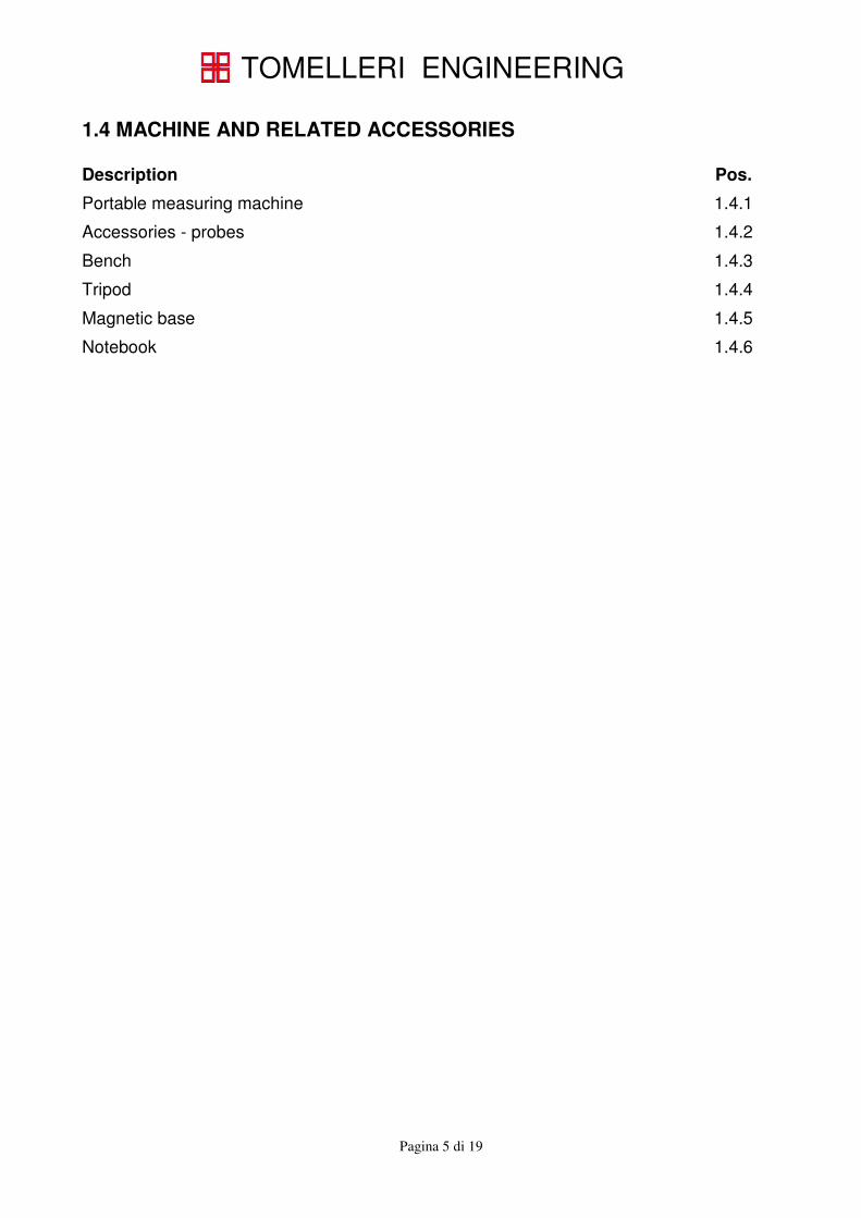
1.4 MACHINE AND RELATED ACCESSORIES Description Pos.
Portable measuring machine 1.4.1
Accessories - probes 1.4.2
Bench 1.4.3
Tripod 1.4.4
Magnetic base 1.4.5
Notebook 1.4.6
TOMELLERI ENGINEERING
Pagina 6 di 19
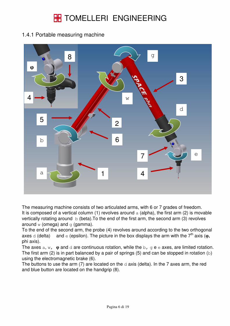
1.4.1 Portable measuring machine
The measuring machine consists of two articulated arms, with 6 or 7 grades of freedom. It is composed of a vertical column (1) revolves around a (alpha), the first arm (2) is movable
vertically rotating around b (beta).To the end of the first arm, the second arm (3) revolves
around w (omega) and g (gamma). To the end of the second arm, the probe (4) revolves around according to the two orthogonal
axes d (delta) � and e (epsilon). The picture in the box displays the arm with the 7th axis (φ,
phi axis).
The axes a, w, φ and d are continuous rotation, while the b, g e e axes, are limited rotation.
The first arm (2) is in part balanced by a pair of springs (5) and can be stopped in rotation (b) using the electromagnetic brake (6). The buttons to use the arm (7) are located on the d axis (delta). In the 7 axes arm, the red and blue button are located on the handgrip (8).
b
a
w
g
d
e
1
3
5
4
2
6
7
φ
4
8
TOMELLERI ENGINEERING
Pagina 7 di 19
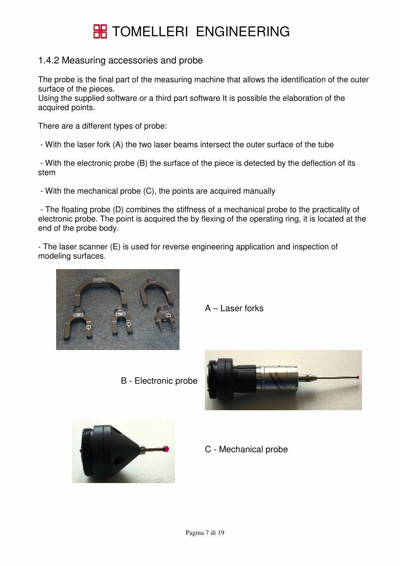
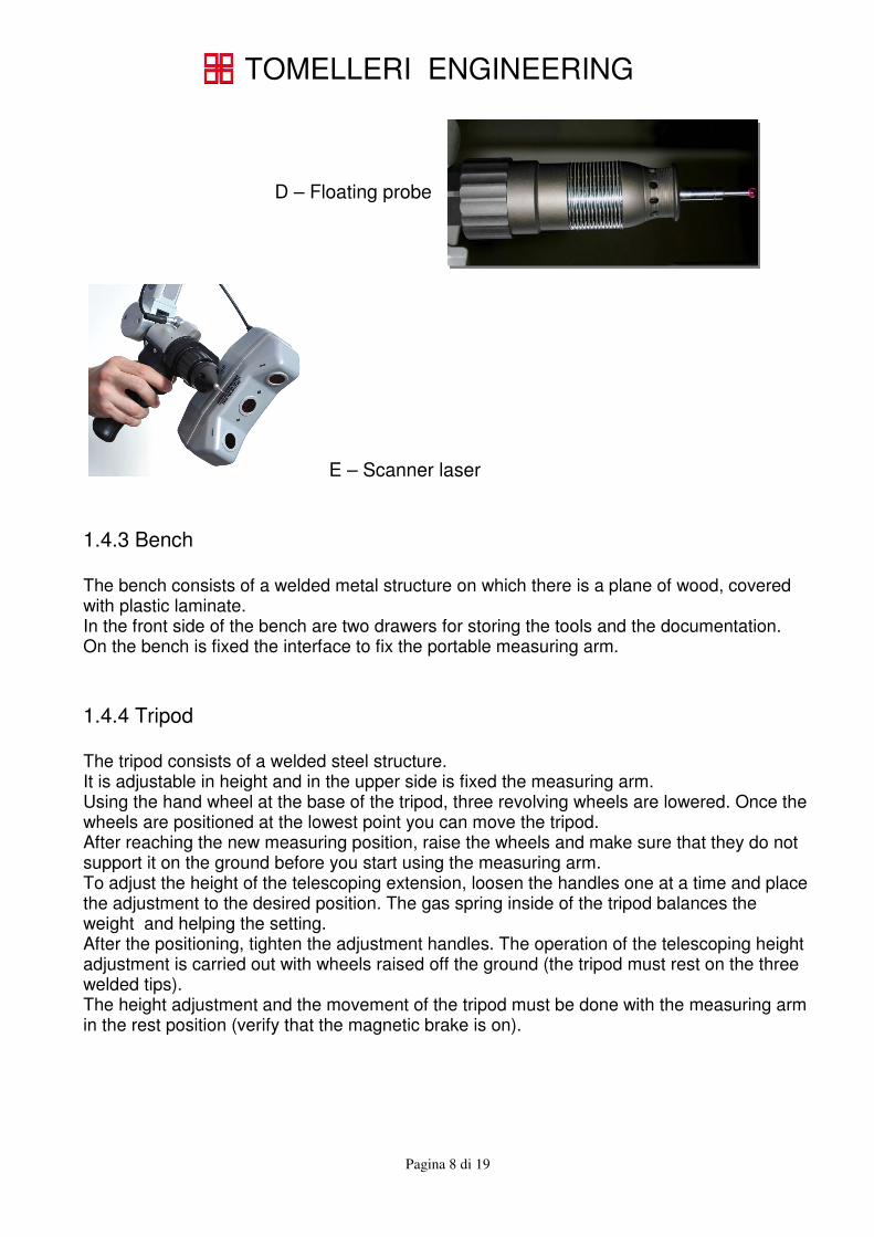
1.4.2 Measuring accessories and probe The probe is the final part of the measuring machine that allows the identification of the outer surface of the pieces. Using the supplied software or a third part software It is possible the elaboration of the acquired points. There are a different types of probe: - With the laser fork (A) the two laser beams intersect the outer surface of the tube - With the electronic probe (B) the surface of the piece is detected by the deflection of its stem - With the mechanical probe (C), the points are acquired manually - The floating probe (D) combines the stiffness of a mechanical probe to the practicality of electronic probe. The point is acquired the by flexing of the operating ring, it is located at the end of the probe body. - The laser scanner (E) is used for reverse engineering application and inspection of modeling surfaces.
A – Laser forks
B - Electronic probe
C - Mechanical probe
TOMELLERI ENGINEERING
Pagina 8 di 19
D – Floating probe
E – Scanner laser
1.4.3 Bench The bench consists of a welded metal structure on which there is a plane of wood, covered with plastic laminate. In the front side of the bench are two drawers for storing the tools and the documentation. On the bench is fixed the interface to fix the portable measuring arm.
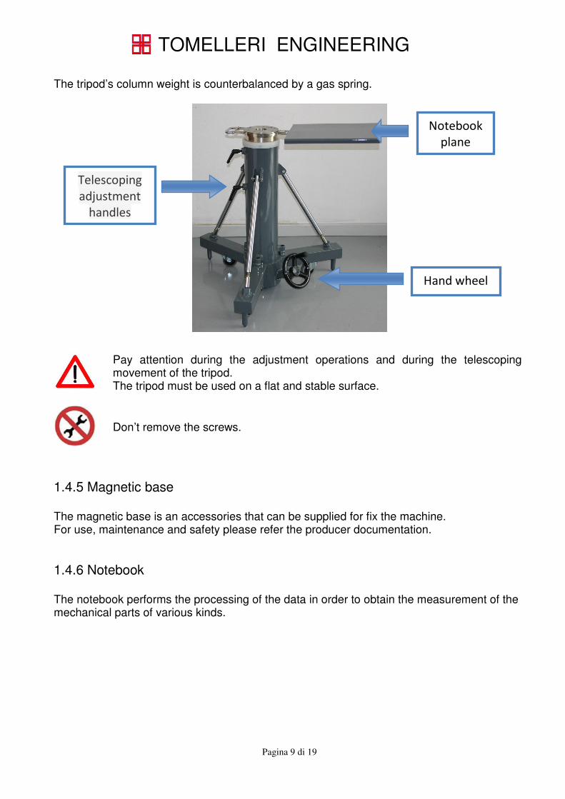
1.4.4 Tripod The tripod consists of a welded steel structure. It is adjustable in height and in the upper side is fixed the measuring arm. Using the hand wheel at the base of the tripod, three revolving wheels are lowered. Once the wheels are positioned at the lowest point you can move the tripod. After reaching the new measuring position, raise the wheels and make sure that they do not support it on the ground before you start using the measuring arm. To adjust the height of the telescoping extension, loosen the handles one at a time and place the adjustment to the desired position. The gas spring inside of the tripod balances the weight and helping the setting. After the positioning, tighten the adjustment handles. The operation of the telescoping height adjustment is carried out with wheels raised off the ground (the tripod must rest on the three welded tips). The height adjustment and the movement of the tripod must be done with the measuring arm in the rest position (verify that the magnetic brake is on).
TOMELLERI ENGINEERING
Pagina 9 di 19
The tripod’s column weight is counterbalanced by a gas spring.
Pay attention during the adjustment operations and during the telescoping movement of the tripod. The tripod must be used on a flat and stable surface.
Don’t remove the screws.
1.4.5 Magnetic base The magnetic base is an accessories that can be supplied for fix the machine. For use, maintenance and safety please refer the producer documentation.
1.4.6 Notebook The notebook performs the processing of the data in order to obtain the measurement of the mechanical parts of various kinds.
Hand wheel
Notebook
plane
Telescoping
adjustment
handles
TOMELLERI ENGINEERING
Pagina 10 di 19
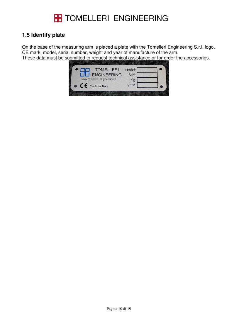
1.5 Identify plate On the base of the measuring arm is placed a plate with the Tomelleri Engineering S.r.l. logo, CE mark, model, serial number, weight and year of manufacture of the arm. These data must be submitted to request technical assistance or for order the accessories.
TOMELLERI ENGINEERING
Pagina 11 di 19
1.6 Important advice
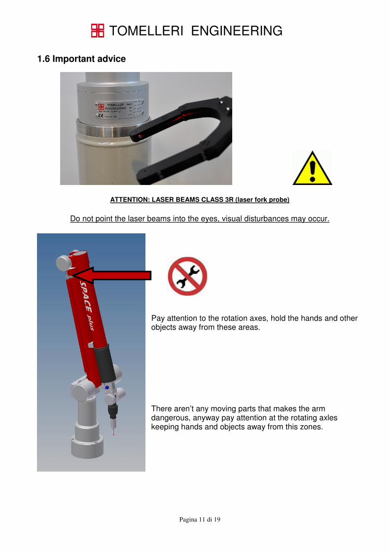
ATTENTION: LASER BEAMS CLASS 3R (laser fork probe)
Do not point the laser beams into the eyes, visual disturbances may occur.
Pay attention to the rotation axes, hold the hands and other objects away from these areas. There aren’t any moving parts that makes the arm dangerous, anyway pay attention at the rotating axles keeping hands and objects away from this zones.

TOMELLERI ENGINEERING
Pagina 12 di 19
1.7 Information about safety and use
• Never allow untrained staff to operate with the measuring arm.
• Use the arm only for the purpose of measuring as described in this manual.
• Before using the arm, always check that it is properly mounted following the instructions in contained this manual. The arm must be mounted vertically on a flat, horizontal and stable surface, or using one of the standard accessories supplied.
• Move the arm carefully to avoid collision with other objects.
• Before measuring please make sure that the probe is properly connected.
• Do not force any part of the probe or the arm structure and avoid extreme angles.
• Don’t adjust the springs load. The changes of the load requires the complete recalibration of the arm performed only by authorized technicians. This changes will be performed only by Tomelleri Engineering technicians.
• The only parts that can be removed are the three hexagonal screw M8 on the base, the communication and power supply cables and the probes. (point 1.9 and 2.0)
• Do not remove, loosen or tighten the screws on the arm or accessories.
• Do not remove or modify any parts of the measuring arm. The only parts that can be connected or used with the arm are the accessories supplied by Tomelleri Engineering S.r.l.
• If the arm is not used, remove the power supply. Please use only the power supply supplied with the measuring arm.
• The electrical ground of the measuring arm is linked to the ground wire through the supplied power pack. We recommend to check the power supply to ensure that the ground connection meets local standards.
• Protect the arm from dust or other contamination. Replace the arm in its case when not in use, or protect it with a dust cover.
• If a magnetic base is in use, do not forget to remove the base before moving the arm to a new location.
• The measuring arm is constructed with high quality materials and therefore doesn’t know any kind of significant wear along the arc of his life, also does not require any user maintenance.
• There may be a loss of precision in the time, in which case you should ask the authorized service technician to obtain service calibration in order to restore the initial conditions.
TOMELLERI ENGINEERING
Pagina 13 di 19
• For cleaning use a cloth lightly dampened with water (and mild detergent if necessary), then wipe with a dry cloth.
Each repair operation must be executed only by authorized technicians.
1.8 Transport Before move the arm, place the arm in its case. The case must be moved by careful and not expose it to weathering.
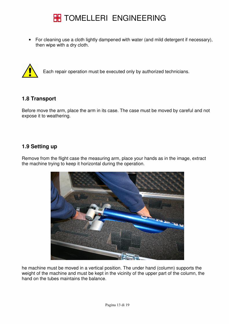
1.9 Setting up Remove from the flight case the measuring arm, place your hands as in the image, extract the machine trying to keep it horizontal during the operation.
he machine must be moved in a vertical position. The under hand (column) supports the weight of the machine and must be kept in the vicinity of the upper part of the column, the hand on the tubes maintains the balance.
TOMELLERI ENGINEERING
Pagina 14 di 19
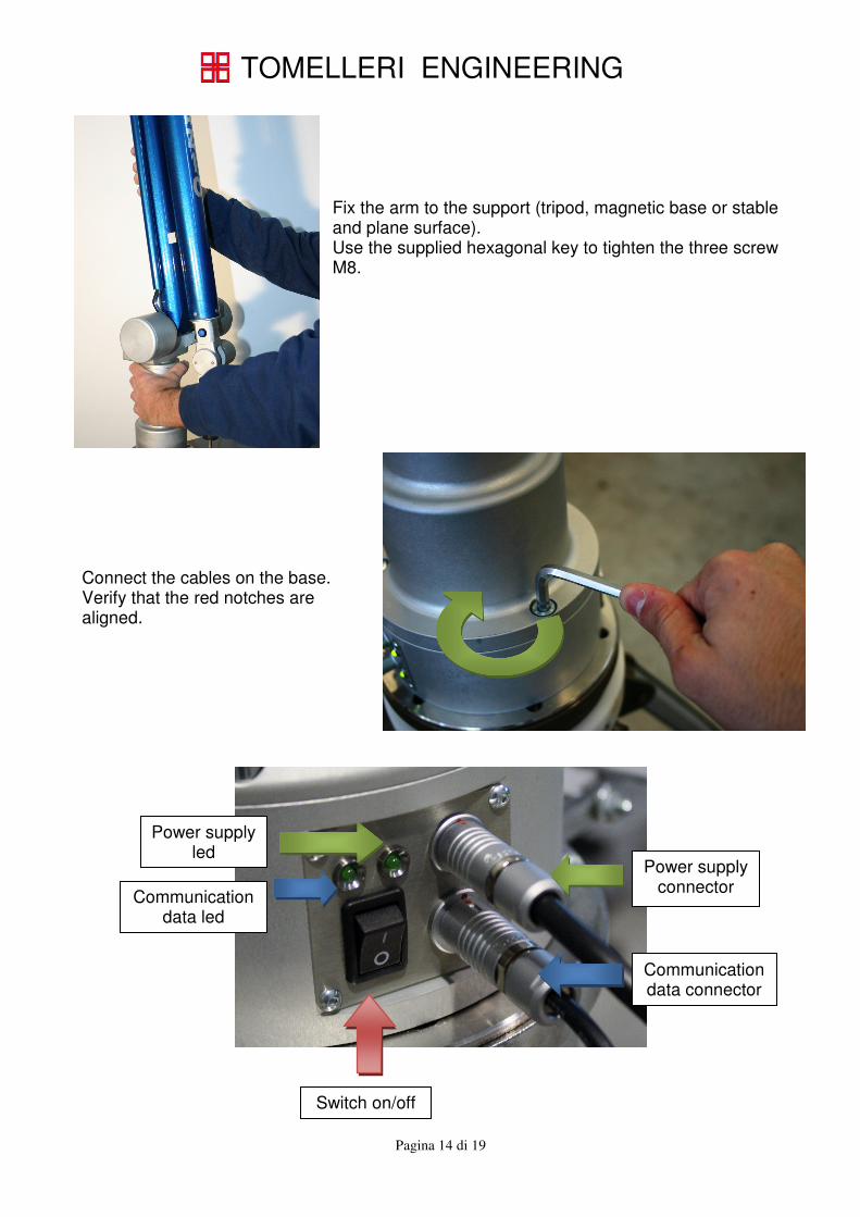
Fix the arm to the support (tripod, magnetic base or stable and plane surface). Use the supplied hexagonal key to tighten the three screw M8.
Connect the cables on the base. Verify that the red notches are aligned.
Communication data connector
Power supply connector
Communication data led
Switch on/off
Power supply led
TOMELLERI ENGINEERING
Pagina 15 di 19
2.0 Mounting and dismounting of the probe The interface on the epsilon and phi axis allows the mechanical and electrical connections between the arm and the probes. The interface allows a fast and repeatable mounting of the probes. During the mounting-demounting of the probes, the arm must be in the rest position and the magnetic brake (if present) must be active. For the mounting or demounting of the probes aren’t required keys or special tools.
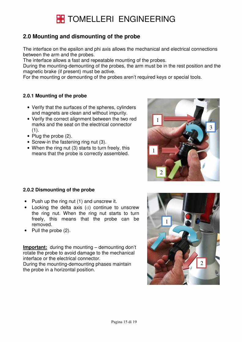
2.0.1 Mounting of the probe
• Verify that the surfaces of the spheres, cylinders and magnets are clean and without impurity.
• Verify the correct alignment between the two red marks and the seat on the electrical connector (1).
• Plug the probe (2).
• Screw-in the fastening ring nut (3).
• When the ring nut (3) starts to turn freely, this means that the probe is correctly assembled.
2.0.2 Dismounting of the probe
• Push up the ring nut (1) and unscrew it.
• Locking the delta axis (d) continue to unscrew
the ring nut. When the ring nut starts to turn freely, this means that the probe can be removed.
• Pull the probe (2). Important: during the mounting – demounting don’t rotate the probe to avoid damage to the mechanical interface or the electrical connector. During the mounting-demounting phases maintain the probe in a horizontal position.
1
1
2
3
1
2
TOMELLERI ENGINEERING
Pagina 16 di 19
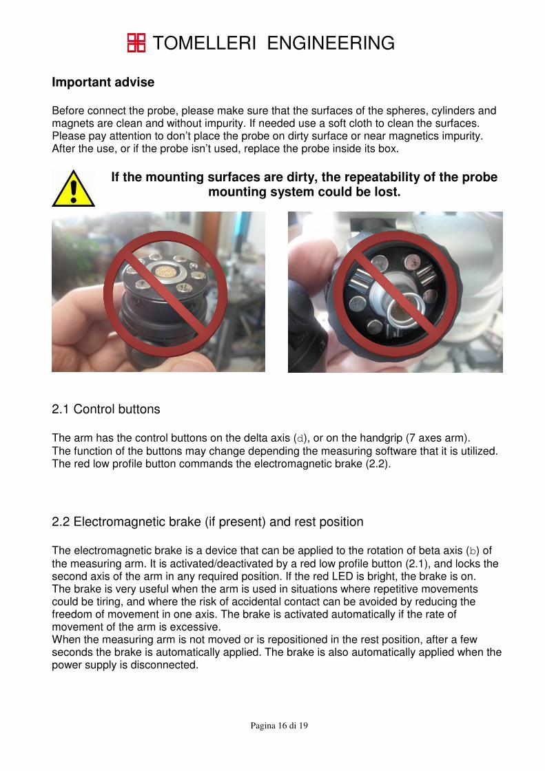
Important advise Before connect the probe, please make sure that the surfaces of the spheres, cylinders and magnets are clean and without impurity. If needed use a soft cloth to clean the surfaces. Please pay attention to don’t place the probe on dirty surface or near magnetics impurity. After the use, or if the probe isn’t used, replace the probe inside its box.
If the mounting surfaces are dirty, the repeatability of the probe mounting system could be lost.
2.1 Control buttons The arm has the control buttons on the delta axis (d), or on the handgrip (7 axes arm). The function of the buttons may change depending the measuring software that it is utilized. The red low profile button commands the electromagnetic brake (2.2). 2.2 Electromagnetic brake (if present) and rest position The electromagnetic brake is a device that can be applied to the rotation of beta axis (b) of the measuring arm. It is activated/deactivated by a red low profile button (2.1), and locks the second axis of the arm in any required position. If the red LED is bright, the brake is on. The brake is very useful when the arm is used in situations where repetitive movements could be tiring, and where the risk of accidental contact can be avoided by reducing the freedom of movement in one axis. The brake is activated automatically if the rate of movement of the arm is excessive. When the measuring arm is not moved or is repositioned in the rest position, after a few seconds the brake is automatically applied. The brake is also automatically applied when the power supply is disconnected.
TOMELLERI ENGINEERING
Pagina 17 di 19
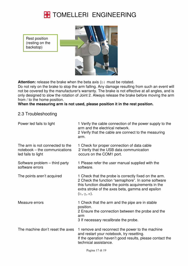
Attention: release the brake when the beta axis (b) must be rotated.
Do not rely on the brake to stop the arm falling. Any damage resulting from such an event will not be covered by the manufacturer's warranty. The brake is not effective at all angles, and is only designed to slow the rotation of Joint 2. Always release the brake before moving the arm from / to the home position. When the measuring arm is not used, please position it in the rest position. 2.3 Troubleshooting Power led fails to light 1 Verify the cable connection of the power supply to the
arm and the electrical network. 2 Verify that the cable are connect to the measuring arm.
The arm is not connected to the notebook – the communications led fails to light
1 Check for proper connection of data cable 2 Verify that the USB data communication occurs on the COM1 port.
Software problem – third party software errors
1 Please refer the user manual supplied with the software.
The points aren’t acquired 1 Check that the probe is correctly fixed on the arm.
2 Check the function “semaphore”. In some software this function disable the points acquirements in the extra stroke of the axes beta, gamma and epsilon (b,g,e).
Measure errors 1 Check that the arm and the pipe are in stable
position. 2 Ensure the connection between the probe and the
arm
3 If necessary recalibrate the probe.
The machine don’t reset the axes 1 remove and reconnect the power to the machine
and restart your notebook, try resetting. If the operation haven’t good results, please contact the technical assistance.
Rest position (resting on the backstop)

TOMELLERI ENGINEERING
Pagina 18 di 19
2.4 Disposal of the machine 2.4.1 Metal parts All the Metal Parts composing the machine can be managed as scrap and then can be recycled by foundry processes. The metal parts of the measuring unit are mainly made of steel and aluminium. 2.4.2 Plastic and rubber parts All the Plastic and Rubber parts must be recycled or disposed of following the NORMS AND THE LAWS IN FORCE of the country where the machine was installed and applying EXCLUSIVELY only to AUTHORIZED AUTHORITIES for these operations. 2.4.3 Electric or electronic components
All the part regarding the Electric or Electronic Components must be recycled or disposed of following the NORMS AND THE LAWS IN FORCE of the country where the machine was installed and applying EXCLUSIVELY only to AUTHORIZED AUTHORITIES for these operations. WARNING: The Electric or Electronic component respects the ROHS norms, but are considered as a highly polluting product then it can’t be disposed of managing it as ordinary waste. 2.4.4 Wooden table The table fixed on the bench is made of wood and is covered by a plastic laminate type DUROPAL and must be recycled or disposed of following the NORMS AND THE LAWS IN FORCE of the country where the machine was installed and applying EXCLUSIVELY only to AUTHORIZED AUTHORITIES for these operations.
TOMELLERI ENGINEERING
MEASURING MACHINES
Viale del Lavoro, 12/A I-37069 VILLAFRANCA (VR)
Tel. +39.045.630.47.44 Fax: +39.045.630.36.57
Mail: [email protected]
Web: www.tomelleri-spacearms.com