Embed Size (px)
Citation preview

Fanuc S-110Karel Palletizing Project
December 19, 2006
Todd MadoleSean McCauley
Rob HaglinMatt Leines
Andy VolkartDan Hovde

Table Of Contents
Objective......................................................................................................................3Program Structuring.....................................................................................................3Main Program..............................................................................................................3Master Program...........................................................................................................4Slave Program..............................................................................................................5Routines.......................................................................................................................6Circuit Development....................................................................................................8Circuit Analysis...........................................................................................................9Master Robot Debugging...........................................................................................15Slave Debugging........................................................................................................16Appendix 1: Program Code with Number Lines.......................................................18Appendix 2: Schematic of Robot Workspace............................................................25Appendix 3: Robot Positioning Table.......................................................................26Appendix 4: Program Flow Diagram........................................................................27
2

Objective
The objective of this laboratory experiment was to integrate all of the robotic programming techniques that have been learned throughout the semester. Then use these techniques to implement an “end of production line” product palletizing routine. The robots in this lab were programmed such that both were capable of being a master or slave depending on how the wiring of the system was configured. Also, the robot master robot was to decipher between tall, short, bad and no parts via a photo sensor. With the information given from the photo sensor the master robot would know which robot had to pick up the part. After a part had been picked the master was to keep a count of the number of parts that had been picked throughout the program. The robot system was also programmed such that if no parts had been sensed by the system after a certain number of tries, the master would then send the slave back to home position and end the program. The last area to be considered by the programmers was letting the robot know how many parts, if any, are on a new pallet. The robots also had to know how to deal with a full pallet. With a full pallet, the users also had to have a way of alerting the robot when it had a new pallet once again. The programming of the robots is very important, but another area that can’t be overlooked is the ability to debug the code. Debugging code was vital to the success of this experiment. Debugging is so important because the programmer could have made minute errors in the code, and the robots won’t run as desired with code errors. Therefore, one must be able to find and fix errors in the code in order to successfully complete this lab. These were all of the main areas to be taken into consideration with the design for each of the robot’s programs.
Program StructuringThe program was coded using the Karel language. There is one main program that identifies whether the robot is master of slave. Each master and slave robot are their own routines that utilize subroutines in the coding. The structuring allows for simpler debugging and the elimination of repetitive code. The team decided to use global variables while programming to allow multiple subroutines to modify the variables. The “correct” way of coding usually does not use global variables. “Correct” coding usually passes values to individual subroutines. The main, master and slave codes are described below. The subroutines referenced in the main coding, are mentioned following the slave description.
Main ProgramThe main program for this project is shown in lines 288-342 in the appended program code. This program starts by initializing the two global variables PAT and ANDY by setting them to 0. These variables will be used in the master routine for full pallet condition statements, such that the conveyor will still advance even if one robot’s pallet is full. Only a situation where both pallets were full would stop the conveyor from running. The program then defines 3 condition statements which will be monitored throughout the length of the program. These conditions are only monitored if the master
3

program is executed; otherwise all three are disabled at the beginning of the slave. Condition 1 monitors for a full pallet condition from the slave, which will occur when DIN[5] is enabled on the master control. The master then acknowledges the slave and activates the red light bulb. A variable PAT is then set to 1000 and condition 2 is enabled, which monitors for DIN[5] to go logic low meaning that the pallet was changed. Upon this event, the master then acknowledges the slave and turns off the red light bulb, setting PAT back to 0. EXPLAIN ROOT OF THIS CONDITON 3Conditionpalletfullcheck 3 monitors pallet replacement condition for the master robot, monitoring for an enabled DIN[6] to signify the full pallet has been replaced (master maintenance button was pushed). ANDY is then reset back to 0, the yellow bulb is deactivated, and the routine PALLETCOUNT is called to determine the both the number of parts on the new pallet and to establish the next placing position on the pallet.
Once the conditions were defined in the main program, condition 1 is enabled and DOUT[8] is turned on. This output port activates the coil on relay 4A shown in Fig. 7, which flips the switch from normally closed to normally open. The normally open side is connected to the AC power supply, which would then send AC power to the input port DIN[16] of whichever robot the relay is connected to. A global variable TOM was set equal to zero, then a repeat until loop incremented TOM by 1 unit followed by a 10 millisecond delay until either the DIN[16] is activated (robot is connected to relay 4A) or until TOM becomes greater than 25. DOUT[8] is then deactivated and the program calls the routine SLAVE if variable TOM exceeded 25. If not, then the MASTER routine is called. Once either the MASTER or SLAVE routine is completed, the main program turns off all of its output ports and terminates.
Master Program
The master routine begins by activating the green light bulb, signifying the program is up and running. The array BOBBY is then initialized using a for-do loop to set each value in the array to zero. The global variables NOPART and COUNTSL are then also set to 0. Then routine PALLETCOUNT is then run to establish an initial placing position on the pallet. The robot then moves to SF2, just above the picking position and the program enters a repeat until loop which begins the picking and placing process of parts from the conveyor. The repeat loop begins by checking if both conditions ANDY= 1000 and PAT= 1000 occur simultaneously, which would represent both master and slave pallets are full. In the event of the loop repeating and seeing this condition as true, it would enter the ‘if’ statement and call up the routine HELPFULL. The global variable NOPART is then checked for a value of less than 50, a variable which is used in as a counter for the number of empty conveyor positions which pass through the photo detector. The global variable JERRY is then set to GIN[1], which is connected to the photo detectors, and the program then scans through four cases through a select structure. Each case represents a reading from the photo detectors.
Case 0 represents a “no part” condition in which neither photo detector goes logic high. This event would then call the subroutine TALLCHECK to check whether a tall part was located in the south robot’s pick location. The global variable NOPART is then incremented by 1.
4

Case 1 represents a “short part,” meaning only the lower photo detector goes logic high. The master then activates its DOUT[1] to tell the slave to pick the part, considering this is the slave’s pick position, and then waits for the acknowledgement to finish the communication between each robot. The global variable COUNTSL is then incremented and the subroutine TALLCHECK is called. NOPART is then reset to 0.
Case 2 represents an error situation in which only the upper photo detector goes logic high. This is obviously an error, but was tested for in the lab to see how the master would react. This event calls up the HELPERROR subroutine which will activate an error lighting scheme in the light bulbs and print out an error message on the controller interface. NOPART is then reset to 0.
Case 3 represents a “tall part” being read into the photo detectors, in which both the lower and upper sensors would go logic high. The subroutine TALLCHECK is then called and NOPART is then reset to 0.
Once a case statement is selected, then the select structure is ended and the routine INCREMENTER is called upon. This routine increments the array ahead one position and then places the value of JERRY from GIN[1] into the first position. Then CONVEYOR is called to move the conveyor one position. This ends the NOPART < 50 if statement and the repeat loop will repeat until NOPART > 30. The program then writes to the screen “Slave has palletized (value of COUNTSL) parts. Hooray!!” The master program is then ended.
Slave Program
The SLAVE routine, displayed on lines 226 through 280, contains the local integer variables TELLIT, ROB and I. First the master robot communicates with the slave to begin the slave routine. Next the slave program calls the routine PALLETCOUNT to determine how many parts are currently on the pallet and moves to SF2 to await further instruction. Initially, ROB is set to 0 so the slave waits until it receives an input on GIN[1]. The slave will receive either 1 or 2 and makes a decision to either pick or go home using the case statement. If a 1 is received, the program calls the routine PICKER to pick up the available part. Next the program checks to see if the pallet is full. When the pallet is full the global integer variable P is greater than 8. While P is less than 8, the program continues to wait for a command from the master. Once the pallet is full, the slave sends a help message to the master via DOUT[2]=ON. The program waits until it receives confirmation that the call for help has been heard on DIN[3]. After the confirmation, the program will wait for either DIN[6] or DIN[2] signified by a pushbutton or signal to go home. If the pushbutton is pressed, PALLETCOUNT will again ask for the amount of parts on the new pallet and end the request for help by turning off DOUT[2]. This loop will continue until it receives a 2 on GIN[1]. In case 2, ROB will be set to 1000. When ROB is set to 1000, the program jumps out of the While loop and acknowledges the request to go home on DOUT[1]. The slave robot waits until the master stops sending a signal across DOUT[2]. The slave program then turns off all of its ports and moves home to SF1 to end the routine.
5

Routines
HELPFULLThe subroutine process HELPFULL, displayed on lines 139 through 152 in Appendix 1, uses a local integer variable defined as Q. A BEGIN-UNTIL loop uses Q as a counter and repeats until one of three conditions happen: Each pass in the loop has a 250 millisecond delay. The loop keeps repeating itself until the integer Q is greater than or equal 60 (60 repetitions through the loop, each repetition delaying for 250 milliseconds, for a total delay of 15 seconds), or if the global integer ANDY is reset to zero, or if the global integer PAT is reset to zero. ANDY and PAT can be reset to zero only by having the pallets cleared and the service button pushed. If ANDY or PAT is reset to zero, the routine ends. If the integer Q reaches a count of greater than or equal to 60, the routine GOHOME is called to send the robots to the home position and the routine ends.
GOHOMEThe subroutine process GOHOME, displayed on lines 155 through 170 in Appendix 1, uses an IF-ELSE condition that states IF the global integer variable TOM has a value less than 25, (south robot is the master because the value of TOM is small), then DOUT [2] turns on. This sends a message to the slave robot to travel home and repeats the command until the master receives an acknowledgement on DIN [4]. DOUT [2] is then set to off and the IF-ELSE condition will end. The ELSE condition is when we are the slave. We turn our DOUT [1] on to acknowledge the message received that was sent by the master on our DIN [2] to travel to home. The slave robot repeats this acknowledgement until the DIN [2] stops receiving the message to go home. The slave then turns the acknowledgement DOUT [1] off. At this point the IF-ELSE condition ends and the south robot, master or slave, moves to the point SF1, sets the NOPART global integer to 1000, and ends the routine GOHOME.
CONVEYORThe subroutine process CONVEYOR, displayed on lines 102 through 110 in Appendix 1, is a simple program that advances the conveyor when the south robot is the master. This program begins by turning DOUT [4] on which sends a signal to advance the conveyor. This signal to advance the conveyor is repeated until a signal is received on DIN [3] that states the conveyor has been incremented. The signal on DOUT [4] is then turned off. A delay of 350 milliseconds is then executed and the CONVEYOR routine ends.
HELPERRORThe subroutine process HELPERROR, displayed on lines 113 through 136 in Appendix 1, is an error routine for the case that the upper photo detector detects a part while the bottom photo detector doesn’t. This routine begins by defining a local integer variable, H, that is used in a REPEAT-UNTIL loop as a counter. Before the loop, the messages “Photo detector error” followed by “press service button to clear,” are programmed in by using the WRITE function. The REPEAT statement in the loop initially increments H and turns DOUT[6] and DOUT[7] to on which are the yellow and red bulbs. There is a 250 millisecond delay and then DOUT[6] and DOUT[7] is turned off followed by another delay of 250 milliseconds. This loop runs for 120 increments of H or until there is a
6

signal received over DIN[6] which is caused by the service button being pushed. If the local integer variable H has a value of more than 120 then an IF-ELSE statement calls the subroutine GOHOME, ELSE it sets DOUT[6] and DOUT[7] to off and ends the routine.
PALLETCOUNTThe routine called PALLETCOUNT is a subroutine which asks for a total number of parts currently on the pallet. Upon calling this routine, the controller interface then writes “Enter number of parts on pallet (0-7)” and waits to read an input set to P, which is a global variable initialized to P= -10 before this initial inquiry for parts. If this input is not an integer number between 0 and 7, the controller will output “Invalid entry, try again” then restates the part inquiry again. The request for the number of parts will repeat until a valid value for the number of palletized parts is read as variable P, which will be used as a target for palletizing. P is then incremented by P= P+1 signifying the next available pallet position.
INCREMETERThe INCREMETER subroutine is used to advance the values stored in the array called BOBBY for each movement of the conveyor. This routine uses a “for” loop to set the value of BOBBY[K] to BOBBY[K-1] for positions 8 down to 2 of the array. Position 1 in the array is then set equal to JERRY, which is set to GIN[1] in the master command and therefore stores a value representing either a tall, short, no part, or error condition.
PICKERThe PICKER routine is comprised of the original picking program written in the first Karel lab with a few minor modifications. The positions can be seen in Appendix 3. This picking routine was also designed to be used both by the master and slave, rather than writing two pick routines. Once PICKER is called, the robot will pick the part from the conveyor and move away from the pick location. An ‘if’ statement then checks whether or not the pallet is full in the event that the robot is set to slave. A full slave pallet during this subroutine would enable a communication between the robots, eventually giving the slave the go ahead to place their part on the new pallet. PLACE was then set equal to PATHPOS (PALLET_PATH, P), P being the global variable set by the PALLETCOUNT routine and represents the next sequential pallet location. Once the part is placed, the robots move back to their waiting pick positions and the value of P is incremented by P= P+1 to define the next pallet position. If the robot is set to master, the subroutine PALLETCHECK is called to see if this called PICKER routine had filled the pallet. Subroutine PICKER is then ended.
PALLETCHECKThe subroutine PALLETCHECK was written to check whether the master’s pallet is full or not. A full pallet causes master turns on the yellow light, sets global variable ANDY= 1000, then enables condition 3 which waits for the new pallet confirmation by monitoring for DIN[6]. Upon receiving this DIN[6], ANDY is reset to 0 and the PALLETCOUNT routine is again called. This ends the routine PALLETCHECK.
TALLCHECK
7

The subroutine process TALLCHECK, displayed on lines 91 through 99 in Appendix 1, is a routine that checks the value of the global integer ANDY and if it isn’t set to a value of greater than 1000 then it checks if the global array BOBBY is set to condition 3. If BOBBY is set to condition 3 then the PICKER routine is called that picks the tall part otherwise the routine ends.
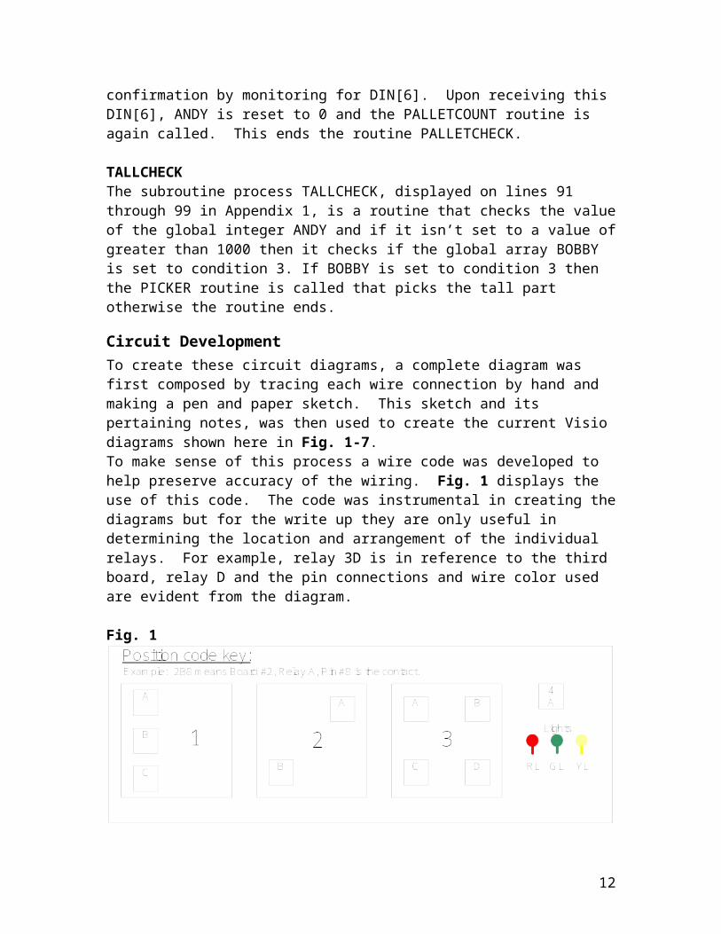
Circuit DevelopmentTo create these circuit diagrams, a complete diagram was first composed by tracing each wire connection by hand and making a pen and paper sketch. This sketch and its pertaining notes, was then used to create the current Visio diagrams shown here in Fig. 1-7.To make sense of this process a wire code was developed to help preserve accuracy of the wiring. Fig. 1 displays the use of this code. The code was instrumental in creating the diagrams but for the write up they are only useful in determining the location and arrangement of the individual relays. For example, relay 3D is in reference to the third board, relay D and the pin connections and wire color used are evident from the diagram.
Fig. 1
The exception to this system is relay 4A, which is a stand alone relay located on top of the South robot control box. The service switches are located on their respective robot controller boxes. All other devices (lights, relay boards, etc…) are located on the conveyor table between the two robots.
The two robots have been previously described as the South and North Robots. They are also often described as Master and Slave. In the complete program to follow in the next few weeks, the robots will have the capability to operate as either Master or Slave depending on a certain input. For this write up, the South Robot will be considered the default Master as it is in direct control of most of the external circuits and the North Robot will be the Slave.
The circuits used can be broken-up/described as four main types of circuits: AC controlled DC circuits, DC controlled AC circuits, and AC controlled AC circuits.
8

Both robot controllers can produce a 24v DC and ground, and an AC positive (L1) and neutral power (L2). Both controllers produce AC signals on the output pins and accept AC signals on the input pins.
Circuit AnalysisThe circuit that drives the part conveyor is shown in Fig. 2. The part conveyor is driven by a pneumatic piston that once activated, will push the conveyor forward a distance limited by a micro switch (Fig. 3), which happens to be the distance required to position a part in the next needed location. This circuit is AC controlled in that the relay coil is connected to the Master robot output pin 4 and the AC neutral pin. The coil will activate upon the Master setting output pin 4 to logic high (on), causing the switch connection to change from normal closed(NC) to normal open(NO). On the output end NC is unconnected while the common(C) is connected to 24VDC on the Master. When switched, NO is connected to the Pneumatic conveyor air driver and completes the circuit because the other driver connection is always connected to DC ground.
Fig. 2
This leads to the conveyor micro-switch circuit (Fig. 3). When this switch is tripped, it signals that the piston has placed the part in the correct place and that it should stop and retract. This is a DC controlled AC circuit as the switch is connected to 24DC power and grounded to the relay coil. The other end of the coil is connected to DC ground causing the coil to activate only if the switch is pressed. NC links the common to AC neutral, once switched to NO it becomes linked to AC power. C is linked to Master input 3, which can be monitored to know when a part is in place, or when to reset the conveyor piston.
9

Fig. 3
Once a part is in position, the type of part (tall or short) needs to be determined. Two photo detectors (Fig. 4) are stacked on top of each other to find this. If the Low detector is activated only, the part is short, if both detectors activate, the part is tall, and if both remain off, no part is available. Both sensors require DC power and ground, provided by the Master. Both relays are wired basically the same, the coils are connected by the DC ground and the output signal generated by its respective sensor. NO is linked to AC power, and NC is linked to AC neutral. C is connected to Master input pin 1 for the Low Detector and input pin 2 for the High Detector. If the sensor detects a part, that activates the coil and sends AC power to the respective input on the Master. Furthermore, these inputs can be grouped in the Master controller to act as a 2 bit word. This should be necessary for determining a tall or short part.
10

Fig. 4
Robot to robot communication is routed by use of 5 relays. These circuits will be utilized to allow the Master to talk to the Slave and vice versa. All are AC controlled AC circuits but the Master provides AC power to NO, AC neutral to NC and Slave AC neutral the coil in Fig. 5. This is reversed in Fig. 6 with the Slave providing for NO and NC, and the Master is linked to the coil. These relays behave as the following:
11
Relay 2A activates Master input pin 5 when Slave output pin 2 is activated. Relay 2B activates Master input pin 4 when Slave output pin 1 is activated.
Relay 1C activates Slave input pin 1 when Master output pin 1 is activated. Relay 1B activates Slave input pin 2 when Master output pin 2 is activated. Relay 1A activates Slave input pin 3 when Master output pin 3 is activated.
Fig. 5
12

Fig. 6
Finally, there are 4 miscellaneous circuits described in Fig. 7. The Master and Slave both have Service Switches that when pressed, will send an AC power to activate input pin 6 on its respective robot controller. These will be used to tell the controller that a service person has performed some function, has safely left the robot work area, and that the robot may start working again.
Relay 4A will activate Master input pin 16 if Master output pin 8 is set to logic high. This will be used to determine/direct whether the North or South robot will act as the Master or the Slave.
Controlled by the Master, and using the Master AC neutral as ground, the status lights behave as the following:
Master output 5 high turns the green Running Status Light on.Master output 6 high turns the yellow Pallet Full Status Light on.Master output 7 high turns the Red Service Status Light on.
These lights will be one of the few ways the service crew will know what state the controller is in, and what may need to be done to keep it running or fix a problem.
13

Fig. 7
14

Master Robot Debugging
The following are the errors that occurred during debugging for the south robot as master and the north robot as the slave:
There were several syntax errors where IF statements required a following THEN statement.
THEN was added to the code where needed
The HELPFUL routine also had a small syntax error that was difficult to track down. PAT was set equal to the letter “O”
Changed the “O” to a zero and then code worked fine.
Routine TALLPARTCHECK had too many characters in its name. Variables, routines and arrays all must be 12 or less characters.
TALLPARTCHECK was changed to TALLCHECK. All the rest of the names were short enough.
There were also several variables that were not initialized. All variables were checked to insure that each was initialized
appropriately.
There were several communication errors in both the slave code and master code for the go home routines
Each error was tracked down and fixed Errors included wrong ports being watched The master code used a then not DOUT[2] instead of then DOUT[2],
which caused the two robots to wait indefinitely.
The robot would try and pick a part too early. The CONVEYOR routine was called too early, before INCREMENTER
was able to advance, causing the conveyor to lag the array. CONVEYOR was moved after INCREMENTER
The most dramatic error during debugging was not code related. The robot attempted to place one part on the table while one was already in that position. This caused the robot to overload the servo motor and eventually stopped itself
The team forgot to move the part off the table and did not follow Dr. Lindeke’s advice on covering both Emergency Stop buttons. The robot had to be shut down and recalibrated in order to continue debugging.
15

If there were two parts in a row and the first part filled the slave’s pallet, it would signal that it was full but after the master told it to get the next part. This caused the slave to pick up the part.
Code was added to the slave program that would say they were full right after they picked up the 8th part. This way the master would be aware of the pallet being full before another part could reach the photo detector.
In the event of Case(2), where the top photo detector was on and the bottom photo detector was off. The master robot would turn the red and orange light on. In order to distinguish between two full pallets and a problem with the part Dr. Lindeke wanted the lights to flash.
Code was modified in lines 142-149 which ran a repeat that turned the orange and red light on and off a quarter of a second a time.
Concluding a successful run of the program, several output ports would remain activated, which required the team having to manually deactivate each port.
In order to confirm that each of the output ports were turned off automatically at the end of the program.
Dr. Lindeke asked that the team kept track of all parts palletized by slave robot Code was added on line 202 and 222 to count the parts.
Slave DebuggingThe following are the errors that occurred during debugging for the north robot as master and the south robot as the slave:
At the start of the program, the robot would move to SF2 without asking for the amount of items on the current pallet.
This was done by adding PALLETCOUNT to line 245 instead of only calling it from line 270
The most problematic part of the debugging process was getting the robots to communicate correctly. The first communication problem caused everything to stop. The master robot was waiting indefinitely for a communication that never occurred.
Lines 237 to 243 were added for the initial handshake in the program.
The slave robot said that it was full too late causing the master to tell it to grab another part, since the pallet was full the slave didn’t respond and the master was stuck in a loop waiting for the slave to say it got the part.
In the picker routine an if statement was added in lines 51-54 that if the robot was slave it would know that it was going to be a full pallet prior to placing the part.
The most difficult problem to identify was after a pallet was filled and the operator pushed the button. The controller would not accept the new input and had to be entered a second time.
16

It was thought that the condition statements were calling PALLETCOUNT. Code was added on lines 234-236 to disable all conditions in the program. This did not fix the problem and it still appeared that PALLETCOUNT was coming from the conditions.
Next, code was added in lines 244, 269, and 282-285 to display where PALLETCOUNT was being called from. This would show on the display exactly where PALLETCOUNT was being called from. This confirmed that the reason the controller would ask twice for an input was that PALLETCOUNT was called in from Condition[3] and then from line 270.
It turned out that PALLETCHECK enabled Condition[3] and would then call the PALLETCOUNT from the condition. Code was added in line 73-75 that only called PALLETCHECK only if the robot was master.
The team also had to do some physical debugging. There was a problem with the wiring connected to slave DOUT[2]. When DOUT[2] was activated it caused interference that caused the orange light relay to flicker.
Dr. Lindeke fixed it by crawling around and the floor and wiggling all the wires, he also used the voltmeter to check the relay that turned the light on.
There were also several variables that were not initialized. All variables were checked to insure that they were initialized
17

Appendix 1: Program Code with Number Lines
1 PROGRAM DAN_BOT12 --3 VAR4 SF1, SF2, SF3, PICK, PLACE:POSITION5 PALLET_PATH:PATH6 COUNTER:INTEGER7 HI_OFF, LO_OFF:REAL8 RATE:INTEGER9 K, NOPART, COUNTSL:INTEGER10 JERRY, ANDY, PAT, P, TOM: INTEGER11 BOBBY: ARRAY [8] OF INTEGER12 --1314 ---user interface--- 15 ROUTINE PALLETCOUNT16 BEGIN17 P= -1018 REPEAT19 WRITE ('ENTER NUMBER OF PARTS ON PALLET (0-7)',CR,CR)20 READ (P)21 IF (P < 0) OR (P > 7) THEN22 WRITE ('INVALID ENTRY, TRY AGAIN',CR,CR)23 ENDIF24 UNTIL (P > -1) AND (P < 8)25 P=P+126 WRITE (CR,CR,CR,CR)27 WRITE ('WE ENTERED ',P-1,CR,CR)28 END PALLETCOUNT293031 ---incrementer for array---32 ROUTINE INCREMENTER33 BEGIN34 FOR K= 8 DOWNTO 2 DO35 BOBBY[K]= BOBBY[K-1]3637 BOBBY[1]= JERRY38 ENDFOR39 END INCREMENTER404142 --picking routine--43 ROUTINE PICKER44 BEGIN45 MOVE NEAR PICK BY HI_OFF46 MOVE NEAR PICK BY LO_OFF47 WITH $TERMTYPE=COARSE,$MOTYPE=LINEAR,$SPEED=150 MOVE TO PICK
18

48 CLOSE HAND 149 MOVE AWAY LO_OFF50 MOVE AWAY (HI_OFF-LO_OFF)51 IF TOM > 25 THEN52 IF P+1 > 8 THEN53 DOUT[2]=ON54 ENDIF55 DOUT[1]= ON56 REPEAT UNTIL NOT DIN[1]57 DOUT[1] = OFF58 ENDIF59 MOVE TO SF260 MOVE TO SF361 --62 PLACE = PATHPOS(PALLET_PATH,P)63 --64 MOVE NEAR PLACE BY HI_OFF65 MOVE NEAR PLACE BY LO_OFF
66 WITH $TERMTYPE=COARSE,$MOTYPE=LINEAR,$SPEED=150 MOVE TO PLACE
67 OPEN HAND 168 MOVE AWAY LO_OFF69 MOVE AWAY (HI_OFF-LO_OFF)70 MOVE TO SF371 MOVE TO SF272 P= P + 173 IF TOM < 25 THEN74 PALLETCHECK75 ENDIF76 END PICKER777879 ---pallet full check---80 ROUTINE PALLETCHECK81 BEGIN82 IF P > 8 THEN83 DOUT[6]= ON84 ANDY=100085 86 ENABLE CONDITION [3]87 ENDIF88 END PALLETCHECK899091 ---checking for tall part, pick and place if so----92 ROUTINE TALLCHECK93 BEGIN94 IF ANDY<1000 THEN95 IF BOBBY[8]=3 THEN96 PICKER97 ENDIF
19

98 ENDIF99 END TALLCHECK100101102 ---conveyor advance---103 ROUTINE CONVEYOR104 BEGIN105 DOUT[4]= ON106 REPEAT107 UNTIL DIN[3]108 DOUT[4] = OFF109 DELAY 350110 END CONVEYOR111112113 ---help-error---114 ROUTINE HELPERROR115 VAR116 H: INTEGER117 BEGIN118 H= 0119 WRITE('PHOTODETECTOR ERROR ',CR,CR)120 WRITE('PRESS SERVICE BUTTON TO CLEAR',CR,CR)121 REPEAT122 H=H + 1123 DOUT[6]=ON124 DOUT[7]=ON125 DELAY 250126 DOUT[6]=OFF127 DOUT[7]=OFF128 DELAY 250129 UNTIL (DIN[6]) OR (H > 120)130 IF H >= 120 THEN131 GOHOME132 ELSE133 DOUT[6]=OFF134 DOUT[7]=OFF135 ENDIF136 END HELPERROR137138139 ---help-full---140 ROUTINE HELPFULL141 VAR142 Q:INTEGER143 BEGIN144 Q= 0145 REPEAT146 Q=Q + 1147 DELAY 250
20

148 UNTIL (ANDY= 0) OR (PAT= 0) OR (Q > 60)149 IF Q >= 60 THEN150 GOHOME151 ENDIF152 END HELPFULL153154155 ---go home---156 ROUTINE GOHOME157 BEGIN158 IF TOM<25 THEN159 DOUT[2]= ON160 REPEAT161 UNTIL DIN[4] 162 DOUT[2]= OFF163 ELSE164 DOUT[1]=ON165 REPEAT UNTIL NOT DIN[2]166 DOUT[1]=OFF167 ENDIF168 MOVE TO SF1169 NOPART= 1000170 END GOHOME171172173 ---master routine---174 ROUTINE MASTER175 BEGIN176 DOUT[5]= ON177 FOR K= 1 TO 8 DO178 BOBBY[K]= 0179 ENDFOR180 NOPART= 0181 COUNTSL= 0182 PALLETCOUNT183 MOVE TO SF2184 REPEAT185 IF (ANDY= 1000) AND (PAT= 1000) THEN186 HELPFULL187 ENDIF188 IF NOPART <50 THEN -------189 JERRY= GIN[1]190 SELECT JERRY OF191 --no part--192 CASE(0):193 TALLCHECK194 NOPART= NOPART + 1195 --short part--196 CASE(1): 197 IF PAT<1000 THEN
21

198 DOUT[1]=ON199 REPEAT200 UNTIL DIN[4]201 DOUT[1]=OFF202 COUNTSL= COUNTSL + 1203 ENDIF204 TALLCHECK205 NOPART=0206 --unknown part--207 CASE(2):208 HELPERROR209 NOPART= 0210 --tall part--211 CASE(3):212 TALLCHECK213 NOPART= 0214 ENDSELECT 215 INCREMENTER216 CONVEYOR217 ENDIF218 UNTIL NOPART > 30219 IF (ANDY<500) OR (PAT<500) THEN220 GOHOME221 ENDIF222 WRITE(CR,'SLAVE HAS PALLETIZED ',COUNTSL,' PARTS. HOORAY!',CR)223 END MASTER224225226 ---slave routine---227 ROUTINE SLAVE228 VAR229 TELLIT, I:INTEGER230 ROB: INTEGER231 BEGIN232 DISABLE CONDITION[1]233 DISABLE CONDITION[2]234 DISABLE CONDITION[3]235 ROB=0236 REPEAT237 TELLIT=GIN[1]238 UNTIL TELLIT > 0239 GOUT[1]=3240 REPEAT241 TELLIT=GIN[1]242 UNTIL TELLIT = 0243 GOUT[1]=0244 WRITE ('GOING TO PALLETCOUNT BEFORE WHILE LOOP',CR,CR)245 PALLETCOUNT246 MOVE TO SF2247
22

248 WHILE ROB < 10 DO249 REPEAT250 ROB= GIN[1]251 UNTIL ROB <> 0252 SELECT ROB OF253 CASE (1):254 PICKER255 CASE (2):256 ROB = 1000257 ENDSELECT258 IF P > 8 THEN 259 I=0260 DOUT[2]= ON261 REPEAT262 UNTIL DIN[3]263 REPEAT 264 UNTIL DIN[6] OR DIN[2]265 IF DIN[2] THEN266 ROB= 1000267 ELSE268 I=I+1269 WRITE ('GOING TO PALLETCOUNT ',I, ' TIMES',CR,CR)270 PALLETCOUNT271 ENDIF272 DOUT[2]=OFF273 ENDIF274 ENDWHILE275 DOUT[1]=ON276 REPEAT UNTIL NOT DIN[2]277 DOUT[1]=OFF278 DOUT[2]=OFF279 MOVE TO SF1280 END SLAVE281 ------282 ROUTINE BIRD283 BEGIN284 WRITE('IN CONDITION 3, BUMMER!!! ',CR,CR)285 END BIRD286287 ---main program---288 BEGIN289 --290 OPEN HAND 1291 $SPEED=RATE292 $TERMTYPE=NODECEL293 --294 PAT=0295 ANDY=0296 CONDITION [1]:297 WHEN DIN[5] DO
23

298 DOUT[3]= ON299 DOUT[7]= ON300 PAT= 1000301 ENABLE CONDITION [2]302 ENDCONDITION303 --304 CONDITION [2]:305 WHEN NOT DIN[5] DO306 DOUT[3]= OFF307 DOUT[7]= OFF308 PAT= 0309 ENABLE CONDITION [1]310 ENDCONDITION311 --312 CONDITION [3]:313 WHEN DIN[6] DO314 ANDY= 0315 BIRD316 PALLETCOUNT317 DOUT[6]=OFF318 ENDCONDITION319 --320 ENABLE CONDITION [1]321 --322 DOUT[8]= ON323 TOM= 0324 REPEAT325 TOM= TOM + 1326 DELAY 10327 UNTIL (DIN[16]) OR (TOM > 25)328 DOUT[8] = OFF329 IF TOM > 25 THEN330 SLAVE331 ELSE332 MASTER333 ENDIF334 DOUT[6]=OFF335 DOUT[5]=OFF336 DOUT[7]=OFF337 DOUT[1]=OFF338 DOUT[2]=OFF339 DOUT[3]=OFF340 DOUT[4]=OFF341 --342 END DAN_BOT1
24

Appendix 2: Schematic of Robot Workspace
25

Appendix 3: Robot Positioning Table
26

Appendix 4: Program Flow Diagram
27