Embed Size (px)
Citation preview
Readers are advised to check the validity of this Certificate by either referring to the BBA’s website (www.bbacerts.co.uk) or contactingthe BBA direct (Telephone Hotline 01923 665400).
1 The Building Regulations 2000 (as amended) (England and Wales)
The Secretary of State has agreed with the British Board of Agrémentthe requirements of the Building Regulations to which formwork cancontribute in achieving compliance. In the opinion of the BBA, Styro
Stone Permanent Insulating Concrete Formwork, if used in accordance with theprovisions of this Certificate, will meet or contribute to meeting the relevantrequirements.Requirement: A1 LoadingRequirement: A2 Ground movementRequirement: A3 Disproportionate collapse
Comment: Walls will have adequate strength and stiffness to satisfythese Requirements. See sections 7.2, 7.3, 9.1 and 9.2 ofthis Certificate.
Requirement: B3(1)(2)(3) Internal fire spread (structure)
Comment: Walls can meet this Requirement. See section 16.1 of thisCertificate. See also section 16.4 of this Certificate.
Requirement: C2(a) Resistance to moisture
Comment: Walls can adequately limit the risk of moisture ingress fromthe ground. See sections 7.2, 7.3, 15.1 and 15.2 of thisCertificate.
Styro Stone GB LtdThe Old Post House91 Heath RoadWeybridgeSurrey KT13 8TSTel: 0871 789 76 78e-mail: [email protected]: www.styrostone.com
AgrémentCertificate
No 06/4339
Designated by Governmentto issue
European TechnicalApprovals
STYRO STONE PERMANENT INSULATING CONCRETE FORMWORKCoffrage perduBetonschalung ortsfest
Product
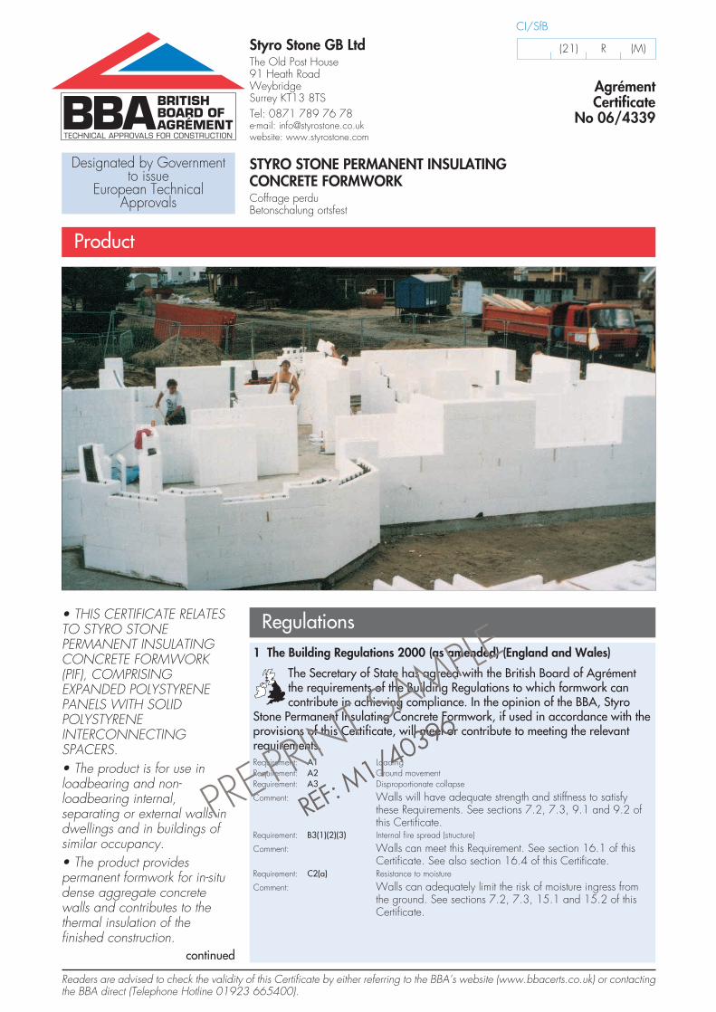
Regulations• THIS CERTIFICATE RELATESTO STYRO STONEPERMANENT INSULATINGCONCRETE FORMWORK(PIF), COMPRISINGEXPANDED POLYSTYRENEPANELS WITH SOLIDPOLYSTYRENEINTERCONNECTINGSPACERS.• The product is for use inloadbearing and non-loadbearing internal,separating or external walls indwellings and in buildings ofsimilar occupancy.• The product providespermanent formwork for in-situdense aggregate concretewalls and contributes to thethermal insulation of thefinished construction.
CI/SfB
(21) R (M)
PRE-PRI
NT SAMPLE
RREEFF:: MM
11//4400339966
continued
2
Requirement: C2(c) Resistance to moisture
Comment: Walls can adequately limit the risk of surface condensationand contribute to minimising the risk of interstitialcondensation. See sections 12.1 and 12.3 of this Certificate.
Requirement: E1 Protection against sound from other parts of the building and adjoining buildingsRequirement: E2 Protection against sound within a dwelling-house, etc.
Comment: Walls can adequately meet these Requirements. Seesections 13.1 to 13.3 of this Certificate.
Requirement: L1(a)(i) Conservation of fuel and power
Comment: Walls can contribute to a building meeting the TargetEmission Rate. See sections 10.1, 10.2, 11.1 and 11.2 ofthis Certificate. Walls can also adequately limit heat loss byunwanted air infiltration and excessive additional heat loss atjunctions between walls, with other elements and aroundopenings. See sections 10.3 to 10.5 of this Certificate.
Requirement: Regulation 7 Materials and workmanship
Comment: The product is acceptable. See sections 19.1 to 19.3 of thisCertificate.
2 The Building (Scotland) Regulations 2004
In the opinion of the BBA, Styro Stone Permanent Insulating ConcreteFormwork, if used in accordance with the provisions of this Certificate,will satisfy or contribute to satisfying the various Regulations and related
Mandatory Standards as listed below.Regulation: 8 Fitness and durability of materials and workmanshipRegulation: 8(1) Fitness and durability of materials and workmanship
Comment: The product can contribute to a construction satisfying thisRegulation. See sections 19.1 to 19.3 and the Installationpart of this Certificate.
Regulation: 9 Building standards — constructionStandard: 1.1(a)(b) StructureStandard: 1.2 Disproportionate collapse
Comment: Walls will have adequate strength and stiffness to satisfy theseStandards, with reference to clause 1.1.1(1)(2) and, whensuitably reinforced, clause 1.2.1(1)(2). See sections 7.2, 7.3,9.1 and 9.2 of this Certificate.
Standard: 2.2 SeparationStandard: 2.3 Structural protection
Comment: Walls can satisfy the short, medium or long fire-resistancedurations required by these Standards, with reference toclauses 2.2.1(1), 2.2.5(1), 2.3.1(1) and 2.3.3(1). Junctionsbetween walls can maintain the required fire-resistancedurations, with reference to clauses 2.1.16(2), 2.2.10(1) and2.3.5(1). See section 16.1 of this Certificate. The expandedpolystyrene component of the wall would be classified ascombustible, however the completed wall can satisfy therequired durations of fire resistance, with reference toclauses 2.1.13(2), 2.1.14(2), 2.2.7(1), 2.2.8(1), 2.3.2(1) and2.3.3(1). See section 16.2 of this Certificate.
Standard: 3.4 Moisture from the ground
Comment: Walls can satisfy this Standard, with reference toclauses 3.4.1(2) and 3.4.5(1). See sections 15.1 and 15.2 ofthis Certificate.
Standard: 3.15 Condensation
Comment: Walls can adequately minimise the risk of surfacecondensation, with reference to clauses 3.15.1(1) and3.15.3(1). See section 12.2 of this Certificate. Walls cancontribute to minimising the risk of interstitial condensation,with reference to clauses 3.15.1(1) and 3.15.4(1). See section12.3 of this Certificate.
Standard: 5.1 Resisting sound transmission to dwellings
Comment: Separating walls can satisfy this Standard, with reference toclauses 5.1.1(1)(2), 5.1.2(1) and 5.1.4(1)(2). See sections 13.1and 13.3 of this Certificate.
PRE-PRI
NT SAMPLE
RREEFF:: MM
11//4400339966
continued
• It is for use with the internaland external finishes.• Subject to design andsupervision by a charteredengineer, the formwork may beused for constructing basementwalls.
3
Standard: 6.2 Building insulation envelope
Comment: Walls will meet the requirements of the Elemental Method forlimiting heat loss, with reference to clause 6.2.1(1)(2). Seesections 10.1, 10.2 and 11.3 of this Certificate. Walls canalso adequately limit heat loss by unwanted air infiltration andexcessive additional heat loss at junctions between walls, withother elements and around openings, with reference toclauses 6.2.4(1)(2) and 6.2.5(1)(2). See sections 10.6 and 10.7of this Certificate.(1) Technical Handbook (Domestic).
(2) Technical Handbook (Non-Domestic).
3 The Building Regulations (Northern Ireland) 2000
In the opinion of the BBA, Styro Stone Permanent Insulating ConcreteFormwork, if used in accordance with the provisions of this Certificate,will satisfy or contribute to satisfying the various Building Regulations as
listed below.Regulation: B2 Fitness of materials and workmanship
Comment: The product is acceptable. See sections 19.1 to 19.3 of thisCertificate.
Regulation: C4 Resistance to ground moisture and weather
Comment: Walls can adequately limit the risk of moisture ingress from theground. See sections 7.2, 7.3, 14, 15.1 and 15.2 of thisCertificate.
Regulation: C5 Condensation
Comment: Walls can contribute to minimising the risk of interstitialcondensation. See section 12.3 of this Certificate.
Regulation: D1 Stability
Comment: Walls will have adequate strength and stiffness to satisfy thisRegulation. See sections 7.2, 7.3, 9.1 and 9.2 of thisCertificate.
Regulation: D2 Disproportionate collapse
Comment: Walls, when suitably reinforced, will have adequate strengthand stiffness to satisfy this Regulation. See sections 7.2, 7.3,9.1 and 9.2 this Certificate.
Regulation: E4(1)(2)(3) Internal fire spread — Structure
Comment: Walls can satisfy this Regulation. See section 16.1 of thisCertificate.
Regulation: F2 Building fabric
Comment: Walls will meet the requirements of the Elemental Method forlimiting heat loss. See sections 10.1 and 10.2 of thisCertificate. Walls can also adequately limit heat loss byunwanted air infiltration and excessive additional heat lossaround openings. See sections 10.8 to 10.10 and 11.4 ofthis Certificate.
Regulation: G2 Separating walls and separating floors
Comment: Separating walls can satisfy this Regulation. See section 13.1of this Certificate.
PRE-PRI
NT SAMPLE
RREEFF:: MM
11//4400339966
4 Construction (Design and Management) Regulations 1994 (as amended)Construction (Design and Management) Regulations (Northern Ireland)1995 (as amended)
Information in this Certificate may assist the client, planning supervisor,designer and contractors to address their obligations under these Regulations.See sections: 6 Site handling and storage (6.4) and 8 Practicability of
installation (8.1 to 8.3).
Technical Specification
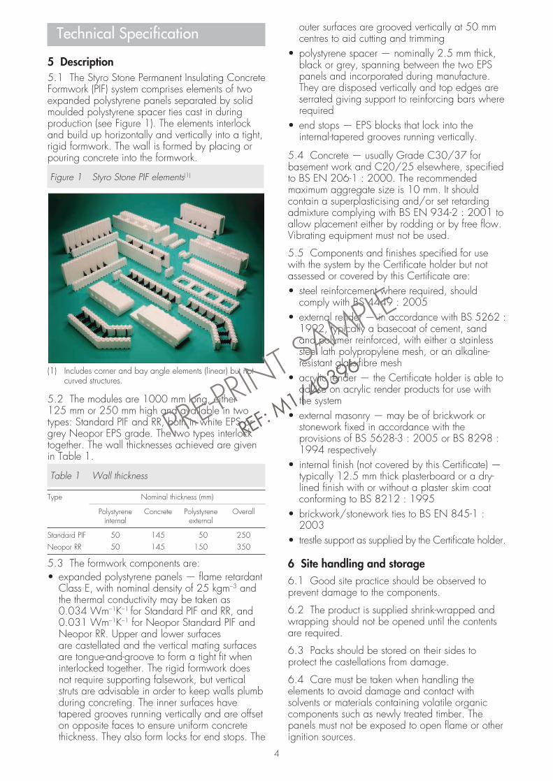
5 Description5.1 The Styro Stone Permanent Insulating ConcreteFormwork (PIF) system comprises elements of twoexpanded polystyrene panels separated by solidmoulded polystyrene spacer ties cast in duringproduction (see Figure 1). The elements interlockand build up horizontally and vertically into a tight,rigid formwork. The wall is formed by placing orpouring concrete into the formwork.
Figure 1 Styro Stone PIF elements(1)
(1) Includes corner and bay angle elements (linear) but notcurved structures.
5.2 The modules are 1000 mm long, either125 mm or 250 mm high and available in twotypes: Standard PIF and RR, both in white EPS orgrey Neopor EPS grade. The two types interlocktogether. The wall thicknesses achieved are givenin Table 1.
Table 1 Wall thickness
Type Nominal thickness (mm)
Polystyrene Concrete Polystyrene Overallinternal external
Standard PIF 50 145 50 250Neopor RR 50 145 150 350
5.3 The formwork components are:• expanded polystyrene panels — flame retardant
Class E, with nominal density of 25 kgm–3 andthe thermal conductivity may be taken as0.034 Wm–1K–1 for Standard PIF and RR, and0.031 Wm–1K–1 for Neopor Standard PIF andNeopor RR. Upper and lower surfacesare castellated and the vertical mating surfacesare tongue-and-groove to form a tight fit wheninterlocked together. The rigid formwork doesnot require supporting falsework, but verticalstruts are advisable in order to keep walls plumbduring concreting. The inner surfaces havetapered grooves running vertically and are offseton opposite faces to ensure uniform concretethickness. They also form locks for end stops. The
outer surfaces are grooved vertically at 50 mmcentres to aid cutting and trimming
• polystyrene spacer — nominally 2.5 mm thick,black or grey, spanning between the two EPSpanels and incorporated during manufacture.They are disposed vertically and top edges areserrated giving support to reinforcing bars whererequired
• end stops — EPS blocks that lock into theinternal-tapered grooves running vertically.
5.4 Concrete — usually Grade C30/37 forbasement work and C20/25 elsewhere, specifiedto BS EN 206-1 : 2000. The recommendedmaximum aggregate size is 10 mm. It shouldcontain a superplasticising and/or set retardingadmixture complying with BS EN 934-2 : 2001 toallow placement either by rodding or by free flow.Vibrating equipment must not be used.
5.5 Components and finishes specified for usewith the system by the Certificate holder but notassessed or covered by this Certificate are:• steel reinforcement where required, should
comply with BS 4449 : 2005• external render — in accordance with BS 5262 :
1992, typically a basecoat of cement, sandand polymer reinforced, with either a stainlesssteel lath polypropylene mesh, or an alkaline-resistant glass-fibre mesh
• acrylic render — the Certificate holder is able toadvise on acrylic render products for use withthe system
• external masonry — may be of brickwork orstonework fixed in accordance with theprovisions of BS 5628-3 : 2005 or BS 8298 :1994 respectively
• internal finish (not covered by this Certificate) —typically 12.5 mm thick plasterboard or a dry-lined finish with or without a plaster skim coatconforming to BS 8212 : 1995
• brickwork/stonework ties to BS EN 845-1 :2003
• trestle support as supplied by the Certificate holder.
6 Site handling and storage6.1 Good site practice should be observed toprevent damage to the components.
6.2 The product is supplied shrink-wrapped andwrapping should not be opened until the contentsare required.
6.3 Packs should be stored on their sides toprotect the castellations from damage.
6.4 Care must be taken when handling theelements to avoid damage and contact withsolvents or materials containing volatile organiccomponents such as newly treated timber. Thepanels must not be exposed to open flame or otherignition sources.
4
PRE-PRI
NT SAMPLE
RREEFF:: MM
11//4400339966
Design Data
7 General7.1 Styro Stone Permanent Insulating ConcreteFormwork (PIF) is satisfactory for use in loadbearingand non-loadbearing internal, separating orexternal walls as permanent formwork for in-situdense aggregate concrete. It acts as lost shutteringand provides a significant contribution to thethermal insulation of new walls.
7.2 Buildings subject to the nationalBuilding Regulations should be constructedin accordance with the relevant
recommendations of BS 8110-1 : 1997,BS 8110-2 : 1985, BS 8102 : 1990 andCP 102 : 1973.
7.3 Other buildings not subject to any of theRegulations defined in section 7.2 should also bebuilt in accordance with BS 8110-1 : 1997,BS 8110-2 : 1985 and CP 102 : 1973.
7.4 The concrete is not easily examined aftercasting, hence, as specified in BS 8110-1 :1997, Section 2, care must be taken to ensure fullcompaction. Compaction may be checked byremoval of a section of EPS panel, observation,and then replacement. Voids are readily detectedduring the concrete placement, by hitting the EPSpanel (eg with the palm of the hand or a woodenmallet) and listening for a ‘hollow’ sound. Suitablesupervision during placing and compacting of theconcrete must be provided.
7.5 Storey-height concrete walls are normallyconstructed in one or more lifts. Particular care isnecessary to maintain alignment during concretefilling, and checking between lifts.
8 Practicability of installation8.1 Installation of the formwork by trainedoperatives, including the forming of door andwindow openings, is practicable. The panels canbe cut using conventional woodworking tools, thuscarpentry skills are appropriate.
8.2 Concrete can be placed by hand, by skipwith adapted neck or by pump. The requirementsgiven in sections 21.10 to 21.13 of this Certificatemust be observed during placing and compactingof the concrete.
8.3 Fixings, suitably durable and mechanicallyadequate, must be supported by the concrete andnot by the polystyrene. Appropriate fasteners maybe post-drilled or cast into the concrete. Inspecifying wall fixings carrying vertical loads,consideration should be given to the line of actionof the load with respect to the face of the concretewall and the effect on the strength of the fixing.
8.4 Consideration should be given at the designstage to the positioning of wall fixings, servicepipes and joists, relative to the position of
connecting assemblies. They can be incorporatedby following the manufacturer’s recommendations.Care must be taken not to damage the elementsand cold bridging effects must be considered.8.5 Facing brickwork or stonework should be fixedto the concrete with stainless steel ties(1). Fixingsshould be applied to the depth recommended bythe manufacturer. See section 5.5.(1) Available from the Certificate holder and can be
customised to suit the application.
8.6 Weatherboarding and hung tiles should befixed to treated battens secured to the in-situconcrete as described in section 8.5 and inaccordance with the Styro Stone TechnicalManual. See section 5.5.
9 Strength and stability9.1 Walls constructed using the productmay be treated as conventional concretewalls and should be designed and
constructed in accordance with therecommendations of BS 8110-1 : 1997 andBS 8110-2 : 1985. Particular attention should bemade to the use of the type of concrete mix toensure segregation does not occur and the wetconcrete is allowed to flow freely around formedopenings and through congested areas ofreinforcement, particularly when the system is usedin basement construction. The Certificate holder isable to provide suitable design mixes on request.9.2 The nominal concrete cover to reinforcementshould be that appropriate to ‘mild’ exposure inaccordance with BS 8110-1 : 1997, Tables 3.2and 3.4, or as required for fire resistance inaccordance with BS 8110-2 : 1985, Section 4,whichever is the greater (see section 21.6 of thisCertificate).9.3 To achieve structurally-stable walls sufficientlyplane for finishings, it will be necessary to bracethe units during construction, check the plumb andalignment of the walls after each lift and makeadjustments to the bracing as necessary. Attentionto the accurate levelling of the foundation andinitial setting out of the bracing (see sections 21.1and 21.24) should prevent the need for significantadjustments to be made.9.4 When used in situations where walls areexposed but have some protection, eg walls ofprivate dwellings and walls of communal dwellingsabove ground-floor level, the render finish hasadequate resistance to impact and abrasion.Guidance may be obtained from the Certificateholder and BRE Current Paper CP 6 : 81Assessment of external walls — Hard body impactresistance.9.5 The render finish, incorporating the fixingmethods and movement joints specified in thisCertificate, will withstand the thermal stresses andwind pressures normally experienced in the UnitedKingdom. In special circumstances (ie in conditions
5
PRE-PRI
NT SAMPLE
RREEFF:: MM
11//4400339966
of severe exposure, as defined in Clause 18 ofBS 5262 : 1991) consideration should be given, atthe corners of buildings and other special riskpositions, to increasing the number of fixings. Typicalpull-out strength for a stainless steel fixing in soundsubstrate is taken as 1000 N and the standardfixing rate is defined as one per square metre.
10 Thermal transmittance
10.1 For the purposes of the U valuecalculations, the nominal thermal conductivityEPS can be taken as 0.034 Wm–1K–1 for
Standard PIF and RR, and 0.031 Wm–1K–1 forNeopor Standard PIF and Neopor RR.
10.2 The thermal transmittance (U value)of external walls can be taken as shown inTable 2, without any contribution from internal andexternal finishes. Calculations for specificconstructions and finishes should be carried out inaccordance with the Combined method inBS EN ISO 6946 : 1997 and BRE 443 : 2006Conventions for U-value calculations document.
Table 2 U values(1)
Type Wm–2K–1
Standard PIF 0.29
Neopor Standard PIF 0.26
Standard RR 0.16
Neopor RR 0.14
(1) See Table 1.
10.3 External walls, typically, can improveon the Elemental U value requirement of theBuilding Regulations (ie 0.35 Wm–2K–1) by
17% to 60% and, therefore, will contribute toenabling a building to meet the Target EmissionRate ‘average’ improvements of 20% (dwellings)and between 23% and 28% (buildings other thandwellings) specified in Approved Documents L1Aand L2A respectively.
10.4 Junctions between external walls andbetween external walls and separating walls willmaintain insulation continuity and the default psivalues from BRE Information Paper IP 1/06Assessing the effects of thermal bridging atjunctions and around openings in the externalelements of buildings, Table 3 and SAP 2005 TheGovernment’s Standard Assessment Procedure forEnergy Rating of Dwellings, Table K1, may beused in Target Emission Rate calculations to SAP2005 or the Simplified Building Energy Model(SBEM)(1). See Figures 2 and 3.
(1) Published by the Department for Communities and LocalGovernment on its website: www.communities.gov.uk
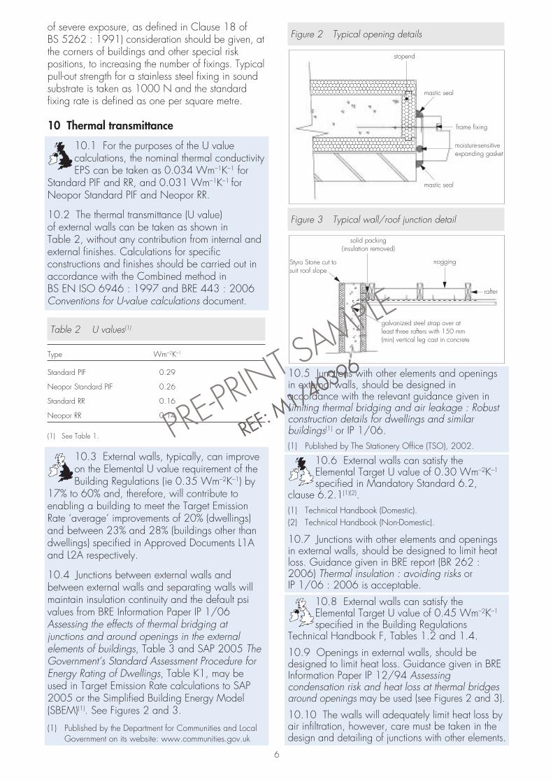
Figure 2 Typical opening details
Figure 3 Typical wall/roof junction detail
10.5 Junctions with other elements and openingsin external walls, should be designed inaccordance with the relevant guidance given inLimiting thermal bridging and air leakage : Robustconstruction details for dwellings and similarbuildings(1) or IP 1/06.(1) Published by The Stationery Office (TSO), 2002.
10.6 External walls can satisfy theElemental Target U value of 0.30 Wm–2K–1
specified in Mandatory Standard 6.2,clause 6.2.1(1)(2).(1) Technical Handbook (Domestic).(2) Technical Handbook (Non-Domestic).
10.7 Junctions with other elements and openingsin external walls, should be designed to limit heatloss. Guidance given in BRE report (BR 262 :2006) Thermal insulation : avoiding risks orIP 1/06 : 2006 is acceptable.
10.8 External walls can satisfy theElemental Target U value of 0.45 Wm–2K–1
specified in the Building RegulationsTechnical Handbook F, Tables 1.2 and 1.4.
10.9 Openings in external walls, should bedesigned to limit heat loss. Guidance given in BREInformation Paper IP 12/94 Assessingcondensation risk and heat loss at thermal bridgesaround openings may be used (see Figures 2 and 3).
10.10 The walls will adequately limit heat loss byair infiltration, however, care must be taken in thedesign and detailing of junctions with other elements.
noggingStyro Stone cut tosuit roof slope
solid packing(insulation removed)
rafter
galvanized steel strap over atleast three rafters with 150 mm(min) vertical leg cast in concrete
frame fixing
moisture-sensitiveexpanding gasket
mastic seal
stopend
mastic seal
6
PRE-PRI
NT SAMPLE
RREEFF:: MM
11//4400339966
11 Air leakage11.1 External walls can provide adequateresistance to heat loss by air infiltration. Careshould be taken to ensure that junctions with
other elements and openings in external walls,comply with the relevant guidance for airtightnessgiven in the relevant documents referred to insection 10.5.
11.2 Completed buildings are subject to pre-completion testing for airtightness in accordancewith the requirements of the Building Regulations,Approved Documents L1A and L2A, Section 20B.
11.3 Junctions with other elements andopenings in external walls, should be designedto limit air infiltration (see section 10.7).
11.4 Junctions with other elements shouldbe designed to limit air infiltration asdescribed in the Building Regulations,
Technical Booklet F, section 1.35.
12 Surface condensation12.1 Walls, openings and junctions withother elements shown in Figures 2 and 3 willadequately limit the risk of surface
condensation when, the thermal transmittance(U value) does not exceed 0.7 Wm–2K–1 at anypoint. Any such junctions with other elements shouldbe designed in accordance with TSO publicationLimiting thermal bridging and air leakage : Robustconstruction details for dwellings and similarbuildings TSO 2002 or BRE document IP 17/01,Assessing the effects of thermal bridging at junctionsand around openings.
12.2 Walls will adequately limit the risk ofsurface condensation when the thermaltransmittance (U value) does not exceed
1.2 Wm–2K–1 at any point. Guidance may beobtained from Section 8 of BS 5250 : 2002 andBRE report (BR 262 : 2002).
12.3 A suitably-positioned vapour controllayer should be used unless a condensationrisk assessment in accordance with BS 5250 :
2002 shows it not to be necessary for the purposesof calculations, a nominal vapour diffusion factor µof 60 (a vapour resistivity of 300 MNsg–1), maybe taken for the EPS component of the system.
13 Sound insulation13.1 Separating walls with a concrete coredensity greater than 2000 kgm–3 andthickness of 150 mm, will achieve a
minimum mass per unit area for the core of300 kgm–2. When used in conjunction with suitableframing, lining and flanking details, the wall canmeet the requirements for a wall Type 3.
13.2 Separating walls in dwellings androoms for residential purposes in Englandand Wales are subject to pre-completion
testing in accordance with Section 1 of ApprovedDocument E.
13.3 Internal walls and walls flankingseparating walls in new dwellings androoms for residential purposes will have a
minimum mass per unit area, excluding finishes, inexcess of 120 kgm–2.
14 WeathertightnessResistance to rain ingress is provided by theexternal weather cladding system. Typicaloptions are described in section 5.5 and
care should be taken to ensure that design andconstruction comply with the relevant good practicedescribed in the applicable Codes and theCertificate holder’s instructions.
15 Damp-proofing and waterproofing15.1 The product will not transmit moisture bycapillary action. The concrete wall formedwith the product should be constructed using
the specified concrete in accordance with Type Bstructures — structures without membrane inBS 8102 : 1990 (see also sections 5.4 and 7.2of this Certificate).15.2 When used below ground level, eg basementor retaining wall, proper waterproofing materials,compatible with EPS must be used on the externalsurface. Where groundwater is present then a suitablecollector drain and backfilling medium should beprovided to eliminate the build up of hydrostatichead behind the wall. The Certificate holder isable to advise on suitable waterproofing materials.
16 Behaviour in relation to fire16.1 Concrete walls with 0.4% to 1%reinforcement and a minimum cover to thereinforcement of 25 mm are assessed as
having a fire resistance of 1.5 hours (long durationin Scotland) in accordance with Table 4.6 ofBS 8110-2 : 1985, provided they have at least aconcrete thickness of 140 mm. Concrete wallscontaining less than 0.4% reinforcement areassessed as having a fire resistance in excess ofone hour, provided they have at least a concretethickness of 150 mm. This assessment does nottake account of any additional protection providedby the internal and external finishes. The use of theformwork with the specified finishes will not reducethe fire resistance of the concrete wall.
16.2 The expanded polystyrene componentof the system would not be classified as non-combustible. For buildings in Scotland,
completed walls with appropriate finishes can satisfythe required durations of fire resistance and maytherefore be used in separating walls. Whereexternal walls are one metre or less from a relevantboundary, the construction should comply with therelevant exceptions on the use of combustiblematerials permitted by the guidance supporting theBuilding Regulations in Scotland.
7
PRE-PRI
NT SAMPLE
RREEFF:: MM
11//4400339966
8
16.3 The risk of fire spread over the internal andexternal wall surfaces will depend on the finishesthat are used. The relevant requirements of thenational Building Regulations should be observed.
16.4 To limit the risk of fire spread betweenfloors in buildings subject to the BuildingRegulations in England and Wales, fire
barriers should be installed at each floor levelabove the first floor, ie starting with the secondstorey. Fire barriers should completely seal thecavity and be chased into the outer EPS formwork.16.5 In buildings other than those described insection 16.4, it is recommended that designersconsider the guidance given in that section.16.6 Care should be taken to ensure that alldetailing at junction adequately maintains therequired periods of fire resistance, that any cavitiesformed in the completed walls are appropriate firestopped and detailing around any openingsprovides sufficient protection to the EPS.
17 Proximity of flues and appliancesWhen installing the product in close proximity tocertain flue pipes and/or heat-producingappliances, the following provisions of the nationalBuilding Regulations should be met:England and WalesApproved Document J3ScotlandMandatory Standard 3.19, clauses 3.19.4(1)(2) to3.19.7(1)(2)
(1) Technical Handbook (Domestic).(2) Technical Handbook (Non-Domestic).
Northern IrelandTechnical Booklet L.
18 Maintenance and repair18.1 Regular checks should be carried out onrender finishes to ensure that any damage isdetected and repaired as soon as possible.18.2 Minor repairs to the system can be carriedout prior to concrete pouring using expandingfoam, supplied by the Certificate holder, to reduceleakage of wet concrete and maintain the thermalintegrity of the EPS.
19 Durability19.1 Concrete walls constructed with theproduct will have a service life of 60 yearsprovided they are designed in accordance
with section 9 and proper maintenance is carriedout in accordance with section 18.19.2 The EPS formwork will have a similar servicelife provided that it is protected from damage bythe external and internal finishes of the wallconstruction and these are adequately maintained.19.3 The solid polystyrene spacers, polypropylenemesh, steel fixing pins, movement joint beads and
profile trims are conventional building materialsand will have a durability compatible with theexpanded polystyrene.
Installation
20 GeneralThe preparation, installation and support of thepanels and application of the specified finishes mustbe in accordance with the Styro Stone TechnicalManual. Particular attention must be given to therequirements given in sections 8.1 to 8.6 of thisCertificate.
21 Procedure21.1 The foundation should be flat and level towithin ±10 mm. Normally, four courses are laidaround the perimeter, aligned and the trestle support,or similar, bolted into position. These are preciselylevelled and adjustments made to the panels withslate shims or dry mortar where necessary. The basepanels should be supported to maintain panel stabilitybefore concrete to a maximum depth of threeblocks height or one metre (whichever is the least)is poured into the PIF to anchor the formwork base.
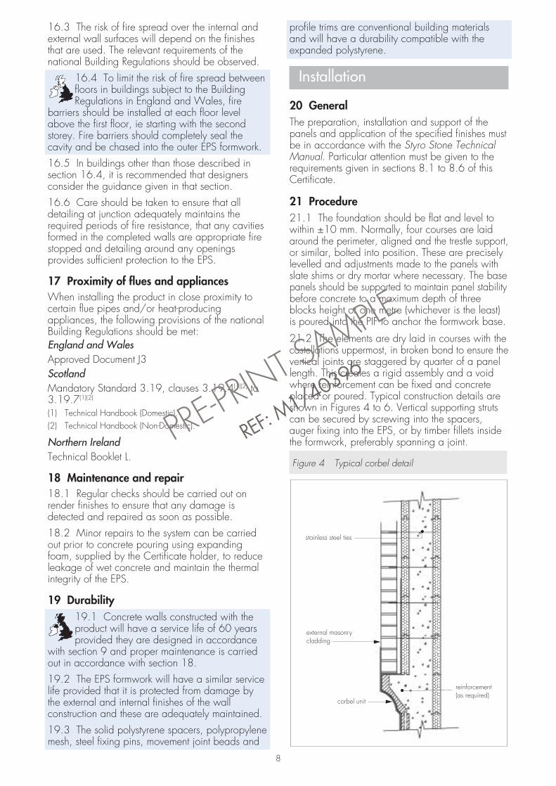
21.2 The elements are dry laid in courses with thecastellations uppermost, in broken bond to ensure thevertical joints are staggered by quarter of a panellength. This creates a rigid assembly and a voidwhere reinforcement can be fixed and concreteplaced or poured. Typical construction details areshown in Figures 4 to 6. Vertical supporting strutscan be secured by screwing into the spacers,auger fixing into the EPS, or by timber fillets insidethe formwork, preferably spanning a joint.
Figure 4 Typical corbel detail
stainless steel ties
external masonrycladding
reinforcement(as required)
corbel unit
PRE-PRI
NT SAMPLE
RREEFF:: MM
11//4400339966
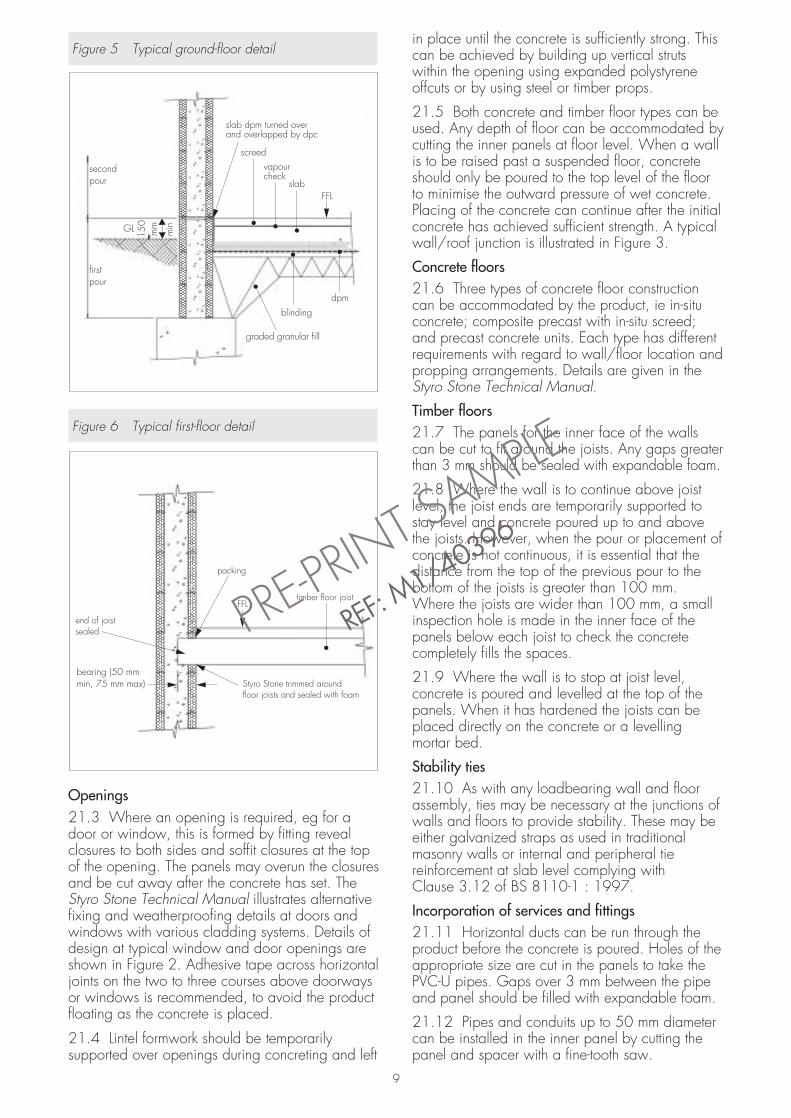
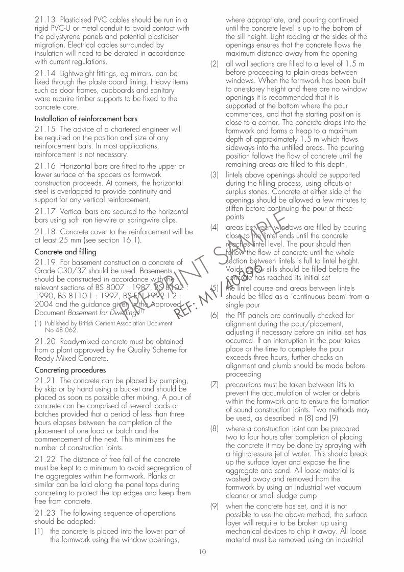
Figure 5 Typical ground-floor detail
Figure 6 Typical first-floor detail
Openings21.3 Where an opening is required, eg for adoor or window, this is formed by fitting revealclosures to both sides and soffit closures at the topof the opening. The panels may overun the closuresand be cut away after the concrete has set. TheStyro Stone Technical Manual illustrates alternativefixing and weatherproofing details at doors andwindows with various cladding systems. Details ofdesign at typical window and door openings areshown in Figure 2. Adhesive tape across horizontaljoints on the two to three courses above doorwaysor windows is recommended, to avoid the productfloating as the concrete is placed.
21.4 Lintel formwork should be temporarilysupported over openings during concreting and left
in place until the concrete is sufficiently strong. Thiscan be achieved by building up vertical strutswithin the opening using expanded polystyreneoffcuts or by using steel or timber props.
21.5 Both concrete and timber floor types can beused. Any depth of floor can be accommodated bycutting the inner panels at floor level. When a wallis to be raised past a suspended floor, concreteshould only be poured to the top level of the floorto minimise the outward pressure of wet concrete.Placing of the concrete can continue after the initialconcrete has achieved sufficient strength. A typicalwall/roof junction is illustrated in Figure 3.
Concrete floors21.6 Three types of concrete floor constructioncan be accommodated by the product, ie in-situconcrete; composite precast with in-situ screed;and precast concrete units. Each type has differentrequirements with regard to wall/floor location andpropping arrangements. Details are given in theStyro Stone Technical Manual.
Timber floors21.7 The panels for the inner face of the wallscan be cut to fit around the joists. Any gaps greaterthan 3 mm should be sealed with expandable foam.
21.8 Where the wall is to continue above joistlevel, the joist ends are temporarily supported tostay level and concrete poured up to and abovethe joists. However, when the pour or placement ofconcrete is not continuous, it is essential that thedistance from the top of the previous pour to thebottom of the joists is greater than 100 mm.Where the joists are wider than 100 mm, a smallinspection hole is made in the inner face of thepanels below each joist to check the concretecompletely fills the spaces.
21.9 Where the wall is to stop at joist level,concrete is poured and levelled at the top of thepanels. When it has hardened the joists can beplaced directly on the concrete or a levellingmortar bed.
Stability ties21.10 As with any loadbearing wall and floorassembly, ties may be necessary at the junctions ofwalls and floors to provide stability. These may beeither galvanized straps as used in traditionalmasonry walls or internal and peripheral tiereinforcement at slab level complying withClause 3.12 of BS 8110-1 : 1997.
Incorporation of services and fittings21.11 Horizontal ducts can be run through theproduct before the concrete is poured. Holes of theappropriate size are cut in the panels to take thePVC-U pipes. Gaps over 3 mm between the pipeand panel should be filled with expandable foam.
21.12 Pipes and conduits up to 50 mm diametercan be installed in the inner panel by cutting thepanel and spacer with a fine-tooth saw.
Styro Stone trimmed aroundfloor joists and sealed with foam
packing
timber floor joistFFL
end of joistsealed
bearing (50 mmmin, 75 mm max)
slab dpm turned overand overlapped by dpc
screedvapourcheck
slab
dpmblinding
graded granular fill
FFL
secondpour
firstpour
GL
150
mm
min
9
PRE-PRI
NT SAMPLE
RREEFF:: MM
11//4400339966
21.13 Plasticised PVC cables should be run in arigid PVC-U or metal conduit to avoid contact withthe polystyrene panels and potential plasticisermigration. Electrical cables surrounded byinsulation will need to be derated in accordancewith current regulations.21.14 Lightweight fittings, eg mirrors, can befixed through the plasterboard lining. Heavy itemssuch as door frames, cupboards and sanitaryware require timber supports to be fixed to theconcrete core.Installation of reinforcement bars21.15 The advice of a chartered engineer willbe required on the position and size of anyreinforcement bars. In most applications,reinforcement is not necessary.21.16 Horizontal bars are fitted to the upper orlower surface of the spacers as formworkconstruction proceeds. At corners, the horizontalsteel is overlapped to provide continuity andsupport for any vertical reinforcement.21.17 Vertical bars are secured to the horizontalbars using soft iron tie-wire or springwire clips.21.18 Concrete cover to the reinforcement will beat least 25 mm (see section 16.1).Concrete and filling21.19 For basement construction a concrete ofGrade C30/37 should be used. Basementsshould be constructed in accordance with therelevant sections of BS 8007 : 1987, BS 8102 :1990, BS 8110-1 : 1997, BS EN 1992-1-2 :2004 and the guidance given in the ApprovedDocument Basement for Dwellings(1)
(1) Published by British Cement Association DocumentNo 48.062.
21.20 Ready-mixed concrete must be obtainedfrom a plant approved by the Quality Scheme forReady Mixed Concrete.Concreting procedures21.21 The concrete can be placed by pumping,by skip or by hand using a bucket and should beplaced as soon as possible after mixing. A pour ofconcrete can be comprised of several loads orbatches provided that a period of less than threehours elapses between the completion of theplacement of one load or batch and thecommencement of the next. This minimises thenumber of construction joints.21.22 The distance of free fall of the concretemust be kept to a minimum to avoid segregation ofthe aggregates within the formwork. Planks orsimilar can be laid along the panel tops duringconcreting to protect the top edges and keep themfree from concrete.21.23 The following sequence of operationsshould be adopted:(1) the concrete is placed into the lower part of
the formwork using the window openings,
where appropriate, and pouring continueduntil the concrete level is up to the bottom ofthe sill height. Light rodding at the sides of theopenings ensures that the concrete flows themaximum distance away from the opening
(2) all wall sections are filled to a level of 1.5 mbefore proceeding to plain areas betweenwindows. When the formwork has been builtto one-storey height and there are no windowopenings it is recommended that it issupported at the bottom where the pourcommences, and that the starting position isclose to a corner. The concrete drops into theformwork and forms a heap to a maximumdepth of approximately 1.5 m which flowssideways into the unfilled areas. The pouringposition follows the flow of concrete until theremaining areas are filled to this depth.
(3) lintels above openings should be supportedduring the filling process, using offcuts orsurplus stones. Concrete at either side of theopenings should be allowed a few minutes tostiffen before continuing the pour at thesepoints
(4) areas between windows are filled by pouringclose to the lintel ends until the concretereaches lintel level. The pour should thenfollow the flow of concrete until the wholesection between lintels is full to lintel height.Voids below sills should be filled before theconcrete has reached its initial set
(5) the lintel course and areas between lintelsshould be filled as a ‘continuous beam’ from asingle pour
(6) the PIF panels are continually checked foralignment during the pour/placement,adjusting if necessary before an initial set hasoccurred. If an interruption in the pour takesplace or the time to complete the pourexceeds three hours, further checks onalignment and plumb should be made beforeproceeding
(7) precautions must be taken between lifts toprevent the accumulation of water or debriswithin the formwork and to ensure the formationof sound construction joints. Two methods maybe used, as described in (8) and (9)
(8) where a construction joint can be preparedtwo to four hours after completion of placingthe concrete it may be done by spraying witha high-pressure jet of water. This should breakup the surface layer and expose the fineaggregate and sand. All loose material iswashed away and removed from theformwork by using an industrial wet vacuumcleaner or small sludge pump
(9) when the concrete has set, and it is notpossible to use the above method, the surfacelayer will require to be broken up usingmechanical devices to chip it away. All loosematerial must be removed using an industrial
10
PRE-PRI
NT SAMPLE
RREEFF:: MM
11//4400339966
vacuum cleaner to leave the surface of theconcrete clean and free from loose material
(10) before a further pour of concrete commences,the formwork is checked to ensure it hasremained clear of debris. When pouringrecommences, a shallow layer (not more than250 mm) of concrete should be placed andwell compacted at the horizontal joint beforecontinuing
(11) vertical contraction joints can be introducedwhere necessary in long, straight walls, byusing crack inducers
(12) after placing the concrete it should beprotected from heavy rain for the first two hours.
Interior and external finishes21.24 A range of external and internal finishescan be applied or fixed directly to the system.Common dry lining systems, such as gypsumplasterboard, can be screw-fixed into the formtie/spacer flanges or glued to EPS usingcompatible adhesive. External cladding systemscan be fixed similarly via battens, rails or into formtie/spacer flanges or with renders applied directlyto the EPS surface in conjunction with metal orplastic lathing. Finishes are outside the scope of thisCertificate. Further details can be obtained from theCertificate holder.
Technical Investigations
The following is a summary of the technicalinvestigations carried out on Styro Stone PermanentInsulating Concrete Formwork.
22 Tests22.1 Tests were undertaken to measuredimensions of the formwork.
22.2 The characteristics of the solid polystyrenespacers were assessed.
23 Investigations23.1 A completed site was visited and theefficiency of concrete compaction was observed.
23.2 A site in progress and after completion wasobserved.
23.3 An assessment was made of data relating tofire performance.
23.4 Condensation and thermal assessments weremade to the requirements of BS 5250 : 2002 andApproved Documents C2 and L1A of England andWales. Calculations for specific constructions andfinishes should be carried out in accordance withthe Combined Method in BS EN ISO 6946 :1997 and BRE 443 : 2006.
Bibliography
BS 4449 : 2005 Steel for the reinforcement ofconcrete — Weldable reinforcing steel — Bar coiland decoiled product — Specification
BS 5250 : 2002 Code of practice for control ofcondensation in buildings
BS 5262 : 1991 Code of practice for externalrenderings
BS 5628-3 : 2005 Code of practice for the use ofmasonry — Materials and components, design andworkmanship
BS 8007 : 1987 Code of practice for design ofconcrete structures for retaining aqueous liquids
BS 8102 : 1990 Code of practice for protectionof structures against water from the ground
BS 8110-1 : 1997 Structural use of concrete —Code of practice for design and constructionBS 8110-2 : 1985 Structural use of concrete —Code of practice for special circumstances
BS 8298 : 1994 Code of practice for design andinstallation of natural stone cladding and lining
BS EN 206-1 : 2000 Concrete — Specification,performance, production and conformity
BS EN 480-2 : 1997 Admixtures for concrete,mortar and grout — Test methods — Determinationof setting time
BS EN 845-1 : 2003 Specification for ancillarycomponents for masonry — Ties, tension straps,hangers and brackets
BS EN 934-2 : 2001 Admixtures for concrete,mortar and grout — Concrete admixtures —Definitions, requirements, conformity, marking andlabellingBS EN 934-3 : 2003 Admixtures for concrete,mortar and grout — Admixtures for masonrymortar — Definitions, requirements, conformity,marking and labelling
BS EN 1992-1-2 : 2004 Eurocode 2 : Design ofconcrete structures. General rules and rules forbuildings. General rules. Structural fire design
BS EN ISO 6946 : 1997 Building componentsand building elements — Thermal resistance andthermal transmittance — Calculation method
CP 102 : 1973 Code of practice for protection ofbuildings against water from the ground
11
PRE-PRI
NT SAMPLE
RREEFF:: MM
11//4400339966
Conditions of Certification
24 Conditions24.1 This Certificate:• relates only to the product/system that is named
and described on the front page• is granted only to the company, firm or person
named on the front page — no other company,firm or person may hold or claim any entitlementto this Certificate
• is valid only within the UK• has to be read, considered and used as a
whole document — it may be misleading andwill be incomplete to be selective
• is copyright of the BBA• is subject to English law.
24.2 References in this Certificate to any Act ofParliament, Regulation made thereunder, Directiveor Regulation of the European Union, StatutoryInstrument, Code of Practice, British Standard,manufacturers’ instructions or similar publication,are references to such publication in the form inwhich it was current at the date of this Certificate.
24.3 This Certificate will remain valid for anunlimited period provided that the product/systemand the manufacture and/or fabrication includingall related and relevant processes thereof:• are maintained at or above the levels which
have been assessed and found to be satisfactoryby the BBA
• continue to be checked as and when deemedappropriate by the BBA under arrangements thatit will determine
• are reviewed by the BBA as and when itconsiders appropriate.
24.4 In granting this Certificate, the BBA is notresponsible for:• the presence or absence of any patent,
intellectual property or similar rights subsisting inthe product/system or any other product/system
• the right of the Certificate holder to manufacture,supply, install, maintain or market theproduct/system
• individual installations of the product or system,including the nature, design, methods andworkmanship of or related to the installation
• the actual works in which the product/system isinstalled, used and maintained, including thenature, design, methods and workmanship ofsuch works.
24.5 Any information relating to the manufacture,supply, installation, use and maintenance of thisproduct/system which is contained or referred to inthis Certificate is the minimum required to be metwhen the product/system is manufactured,supplied, installed, used and maintained. It doesnot purport in any way to restate the requirementsof the Health & Safety at Work etc Act 1974, or ofany other statutory, common law or other dutywhich may exist at the date of this Certificate or inthe future; nor is conformity with such information tobe taken as satisfying the requirements of the 1974Act or of any present or future statutory, commonlaw or other duty of care. In granting thisCertificate, the BBA does not accept responsibilityto any person or body for any loss or damage,including personal injury, arising as a direct orindirect result of the manufacture, supply,installation, use and maintenance of thisproduct/system.PRE
-PRINT SAMPLE
RREEFF:: MM
11//4400339966
In the opinion of the British Board of Agrément, Styro Stone Permanent Insulating ConcreteFormwork is fit for its intended use provided it is installed, used and maintained as set out in thisCertificate. Certificate No 06/4339 is accordingly awarded to Styro Stone GB Ltd.
On behalf of the British Board of Agrément
Date of issue: 27th July 2006 Chief Executive
British Board of AgrémentP O Box No 195, Bucknalls LaneGarston, Watford, Herts WD25 9BAFax: 01923 665301
©2006For technical or additional information,contact the Certificate holder (seefront page).For information about the AgrémentCertificate, including validity andscope, tel: Hotline 01923 665400,or check the BBA website.
e-mail: [email protected]: www.bbacerts.co.uk