Embed Size (px)
Citation preview
UNCLASSIFIED
AD NUMBER
ADB310375
NEW LIMITATION CHANGE
TOApproved for public release, distributionunlimited
FROMDistribution authorized to U.S. Gov't.agencies and their contractors;Administrative/Operational Use; JAN 2005.Other requests shall be referred to AirForce Institute for OperationalHealth/RSEQ, 2513 Kennedy Circle, BrooksCity-Base, TX 78236-5116.
AUTHORITY
711th HPW/OMA [STINFO] ltr dtd 4 Feb 2009
THIS PAGE IS UNCLASSIFIED

IOH-RS-BR-SR-2005-0002
UNITED STATES AIR FORCEAFIOH
Sampling and Analysis Plan for theCollection of Ambient Air Samplesat Receptor Locations from Open
Pit Burning Operations in theDeployed Environment
Nancy L. Hanna-Beauregard
Trajen, Incorporated- 3131 BriarcrestEBryan, TX 77802
Mark D. Wade
Karta Technologies, Incorporated5555 Northwest ParkwaySan Antonio, TX 78249
Vincent D. Falls, Captain, USAF, BSCLuis J. Medina
January 2005
Air Force Institute for Operational HealthRisk Analysis DirectorateEnvironmental Analysis Division
Approved for public release; 2513 Kennedy Circle
distribution is unlimited. Brooks City-Base TX 78235-5116

NOTICES
Publications of this report does not constitute approval or disapproval of the ideas orfindings. It is published in the interest of scientific and technical information (STINFO)exchange.
When Government drawings, specifications, or other data are used for any purpose otherthan in connection with a definitely Government-related procurement, the United StatesGovernment incurs no responsibility or any obligation whatsoever. The fact that theGovernment may have formulated or in any way supplied the said drawings, specification, orother data, is not to be regarded by implication, or otherwise in any manner construed, aslicensing the holder or any other person or corporation; or as conveying any rights or permissionto manufacture, use, or sell any patented invention that may in any way be related thereto.
The mention of trade names or commercial products in this publication is for illustrationpurposes and does not constitute endorsement or recommendation for use by the United StatesAir Force.
The Office of Public Affairs has reviewed this report, and it is releasable to the NationalTechnical Information Service, where it will be available to the general public, including foreignnationals.
The report has been reviewed and is approved for publication.
Government agencies and their contractors registered with Defense Technical InformationCenter (DTIC) should direct requests for copies to: Defense Technical Information Center, 8725John J. Kingman Rd., Suite 0944, Ft Belvoir, VA 22060-6218.
Non-Government agencies may purchase copies of this report from: National TechnicalInformation Services (NTIS), 5285 Port Royal Road, Springfield, VA 22161-2103.
L AD. HAR Major, U , BSC L BORLAN AF, BSCTechnical Project Manager Chief, nvironmental Analysis Division

REPORT DOCUMENTATION PAGE Form ApprovedR DOMB No. 0704-0188
ublic reporting burden for this collection of information Is estimated to average 1 hour per response, including the time for reviewing instructions, searching existing dasle sources,galhering end maintaining the data needed, and completing and reviewing the collection of information. Send comments regaring this burden estimate or any other aspect of lhis
collection of infornaton. rncluding suggestiorns for reducing this burden, to Washinglon Headquarters Seryices, Directorate for Information Operations and Reports. 1215 JeffersonDavis Highway. Su Ite 1204. Arlingtonr. VA 22202-4302, and to the Office of Management end Budget, Paperwork Reduction Project (0704.0188), Washington, DC 20503.
1. AGENCY USE ONLY (Leave blank) 2. REPORT DATE 3. REPORT TYPE AND DATES COVERED
January 2005 Final4. TITLE AND SUBTITLE 5. FUNDING NUMBERS
Sampling and Analysis Plan for the Collection of Ambient Air Samples at ReceptorLocations from Open Pit Burning Operations in the Deployed Environment
6. AUTHORIS)
* Nancy L. Hanna-Beauregard
Vincent D. Falls; Luis J. Medina
** Mark D. Wade7. PERFORMING ORGANIZATION NAME(S) AND ADDRESS(ES) S. PERFORMING ORGANIZATION*Trajen Incorporated **Karta Technologies, Incorporated REPORT NUMBER
3131 Briarcrest 5555 Northwest ParkwayBryan, TX 77802 San Antonio, TX 78249
9. SPONSORING/MONITORING AGENCY NAME(S) AND ADDRESS(ES) 10, SPONSORING/MONITORINGAir Force Institute for Operational Health AGENCY REPORT NUMBER
Risk Analysis Directorate IOH-RS-BR-SR-2005-0002Environmental Analysis Division2513 Kennedy CircleBrooks City-Base TX 78235-511611. SUPPLEMENTARY NOTES
12a. DISTRIBUTION AVAILABILITY STATEMENT 12b. DISTRIBUTION CODE
Distribution Statement A: Approved for public
release; distribution is unlimited.
13. ABSTRACT (Maximum 200 words)Open pit burning is a common practice to dispose of solid waste at deployed locations. Pits are ideally located down wind ofinhabited areas; however, changes in wind direction may cause personnel exposure to the smoke. This guide provides ageneral sampling strategy to address these exposures based on possible contaminants of concern. Included are specificambient air sampling protocols, analysis methodologies, laboratory contacts and sample shipment requirements.
14. SUBJECT TERMS 15. NUMBER OF PAGESopen pit burning, solid waste burning, deployment, ambient air monitoring, air pollution, air 76sampling, air monitoring 16. PRICE CODE
17. SECURITY CLASSIFICATION 18. SECURITY CLASSIFICATION 19. SECURITY CLASSIFICATION 20. LIMITATION OF ABSTRACTOF REPORT OF THIS PAGE OF ABSTRACT
UNCLASSIFIED UNCLASSIFIED UNCLASSIFIED ULStandard Form 298 (Rev. 2-891 1EGPrescribed by ANSI Std. 239.1Designed using Perform Pro. WHS/DIOR. Oct 94

THIS PAGE INTENTIONALLY LEFT BLANK
ii

TABLE OF CONTENTS
PAGELIST OF TABLES iv1. INTRODUCTION 12. OBJECTIVE 13. SAMPLE TYPES 14. SAMPLING FREQUENCY 25. SAMPLING PROCEDURES 36 SAMPLING EQUIPMENT & ANALYSES 4
Appendix A: MiniVol Field Manual 7Appendix B: SUMMA Canister Sampling for Ambient VOCs - (TO-14A) 31Appendix C: PSI Sampling Instructions - (TO-14A) 45Appendix D: Oil Well Fire Equipment List 65
111U
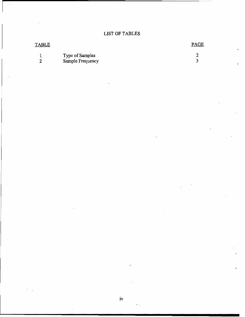
LIST OF TABLES
TABLE PAGE
1 Type of Samples 22 Sample Frequency 3
iv
SAMPLING AND ANALYSIS PLAN FOR THE COLLECTION OFAMBIENT AIR SAMPLES AT RECEPTOR LOCATIONS FROM OPEN
PIT BURING OPERATIONS IN THE DEPLOYED ENVIRONMENT
1. Introduction
In response to a CENTAF (F)/SG Priority A task concerning the health effects of solid wasteburning at OIF sites, the Air Force Institute of Operational Health, Risk Analysis Directorate,Environmental Analysis Division (AFIOH/RSE) developed a sampling and analysis plan for thecollection of ambient air samples to quantify air contaminants produced by open pit burningoperations. The plan is devised so that samples can be taken at receptor locations in thedeployed environment. AFIOH/RSE personnel researched and identified the samplingtechnologies needed to capture the exposures, developed a list of possible contaminants, andassessed the costs involved with the ambient air sampling process. This sampling plan isintended to provide the specific ambient air sampling protocols and analysis methodologiesrequired for deployed base-level personnel to initiate sample collection, shipment and analysesnecessary to quantify the levels of contaminants generated by open pit burning. The ambient airsampling methodologies and analytical methods applied in this plan are based on methodologiesdeveloped by the U.S. Environmental Protection Agency (EPA). Specific, step-by-stepinstructions for air sample collection procedures are outlined in detail in U.S. Army Center forHealth Promotion and Preventive Medicine (USACCHPPM) Technical Guide (TG) 251.
The air pollutants of concern are generated during the open pit burning of solid waste. Specifictypes/amounts of each pollutant depend on the composition of the waste materials being burned.Heat and airflow also contribute to the amount of contaminants released in air becauseincomplete combustion that results in low heat and smoldering tends to produce more smoke.Generally, pollutants may include varying amounts of dioxins, furans, particulate matter,polycyclic aromatic hydrocarbons, volatile organic compounds, carbon monoxide, andhexachlorobenzene. Ambient air samples will be collected during the open pit bum operationsat receptor sites affected. Affected sites will depend on -local meteorological conditions and theirimpact on the plume direction and concentration.
2. Objective
The objective of this sampling and analysis plan is to provide to the deployed BEE the type ofsamples to collect, the method of sampling to use, and the proper analysis to request whenquantifying the exposure levels of deployed personnel to contaminants generated during open pitburning. This plan is generic in nature so that it can be applied to most receptor locations.
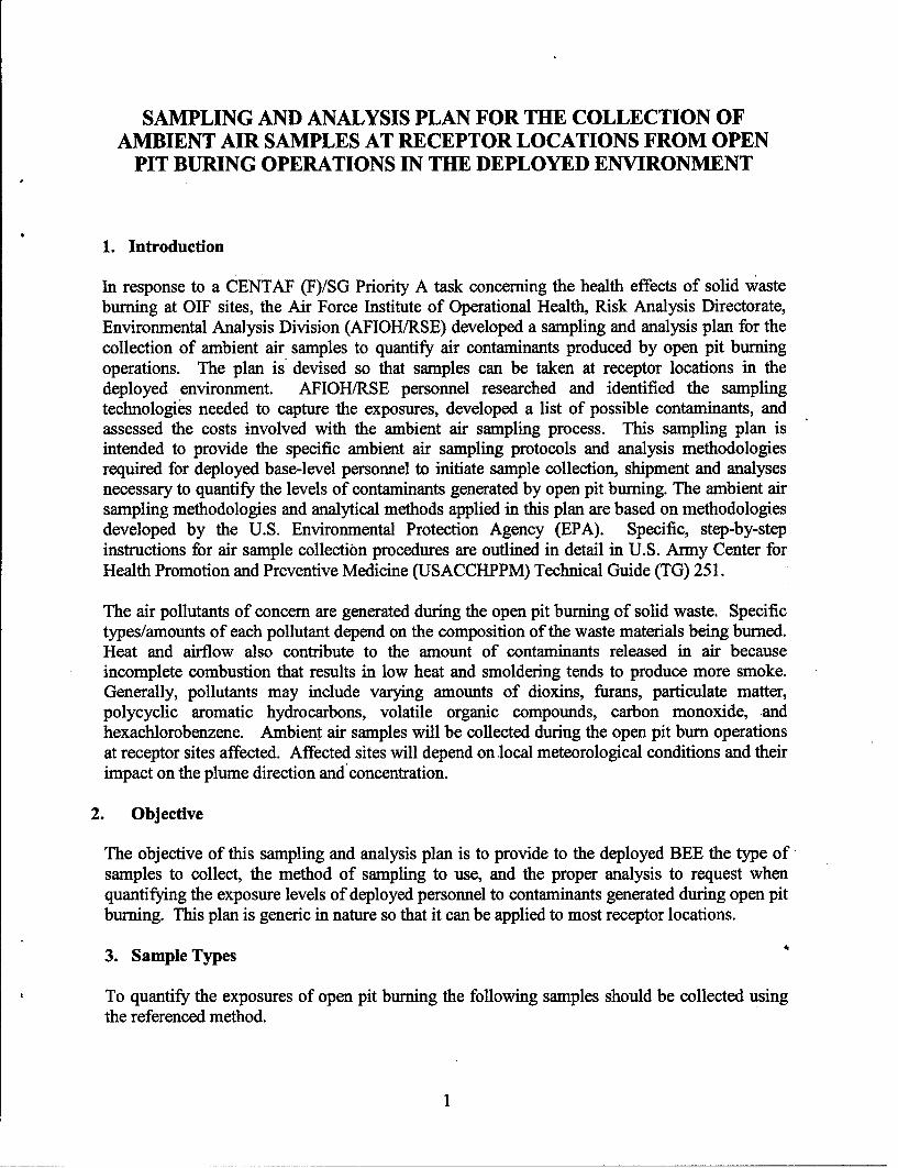
3. Sample Types
To quantify the exposures of open pit burning the following samples should be collected usingthe referenced method.
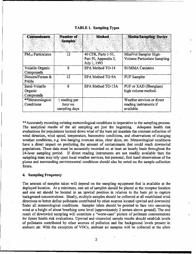
TABLE 1. Sampling Types
Contaminants Number of Method Media/Sampling Device
Samples
PM10 Particulates 12 40 CFR, Parts 1-5 1, MiniVol Sampler High-Part 50, Appendix J, Volume Particulate SamplingJuly 1, 1993
Volatile Organic 8 EPA Method TO-14 SUMMA CanistersCompounds ....Dioxins/Furans & 12 EPA Method TO-9A PUF SamplerPAHsSemi-Volatile 8 EPA Method TO-13A PUF or XAD (fiberglass)Organic high volume method.Compounds**Meteorological 1 reading per Weather services or directConditions hour on reading instruments if
sampling days available
**Accurately recording existing meteorological conditions is imperative to the sampling process.
The analytical results of the air sampling are just the beginning. Adequate health riskevaluations for populations located down wind of the bum pit mandate the constant collection ofwind direction, wind speed, temperature, barometric conditions, and observations of changingweather conditions, e.g. low-hanging overcast skies, clear skies, etc. Meteorological conditionshave a direct impact on predicting the amount of contaminants that could reach downwindpopulations. These data must be accurately recorded on at least an hourly basis throughout the24-hour sampling period. If direct reading instruments are not readily available then thesampling team may rely upon local weather services, but personal, first hand observations of theplume and surrounding environmental conditions should also -be noted on the sample collectionforms.
4. Sampling Frequency
The amount of samples taken will depend on the sampling equipment that is available at thedeployed location. At a minimum, one set of samples should be placed at the receptor locationand one set should be located in an upwind position in relation to the bum pit to capturebackground concentrations. Ideally, multiple samples should be collected at all established winddirections to better define pollutants contributed by other sources located upwind and downwindfinder all meteorological conditions. Sampler inlets should be pointed to face into oncomingwind at a height of about breathing zone level (approximately 2 meters above ground). The endresult of downwind sampling will constitute a "worst-case" picture of pollutant concentrationsfor future health risk evaluations. Upwind and crosswind sample results should establish levelsof pollutants contributed by other sources of pollution and the background levels present inambient air. With the exception of VOCs, ambient air samples will be collected at the afore
2
mentioned locations over periods of 24 hours beginning immediately after bum initiation andcontinually throughout the 24-hour bum period or until combustion is complete, to includesmoldering periods. To measure dioxins and furans in their expected concentration range thesampling period will have to be extended from the EPA Method TO-9A time of 24 hours to 72hours. This will allow enough volume of air to pass through the sampler so that a measurableamount of contaminant is collected. Sampling frequency is illustrated in chart provided below:
Table 2. Sampling Frequency
Wind Direction:Sample NE SE SW NW RECEPTORLocation: (background) (background) (background) (background) LocationDioxins/Furans 2- 72 hour 2- 72 hour 2- 72 hour 2- 72 hour 4- 72 hour
samples samples samples samples samplesVOCs 1 - 8 hour 1- 8 hour 1- 8 hour 1- 8 hour 4- 8 hour
samples samples samples samples samplesParticulates 2- 24 hour 2- 24 hour 2- 24 hour 2- 24 hour 4- 24 hour(PM1O) 24 hour samples samples samples samples samplessamplesMeteorological Hourly x 72 Hourly x 72 Hourly x 72 Hourly x 72 Hourly x 72Data Collection hours hours hours hours hours
5. Sampling Procedures
Particulate Sampling - Airmetrics MiniVol Particulate Sampler Instructions
The MiniVol samples the air at 5 liters per minute for particulate matter (TSP, PM10, andPM2.5). The sampler is designed to be portable to sample the air at a discrete location or to beused in saturation sampling. Electrical power or a permanent structure is not required. While theMiniVol is not EPA approved as a reference method, it has been proven to equivalent to thestandard reference methods. The sample battery pack is designed for 24-hour continuoussampling. For detailed sample collection procedures of PM10 samples using the MiniVol PMSampler, refer to the AFIOH Field Manual (v4.2), March 2000, provided in Attachment 1.
VOC Sampling - Ambient Air Volatile Organic Compound (VOC) Summa CanisterSampling (TO-14A)
VOCs are collected according to EPA Method TO-14A using SUMMA polished, evacuatedstainless steel canisters. Sub-atmospheric, passive, sampling does not require a power source.This type of sampling provides a high level of portability for remote field sampling. Samplingperiods from 8 hours, 24 hours, and up to one week may be selected for the sampling missionrequirements. Eight-hour samples are all that is required for this particular sampling plan. Flowrates are determined by the capacity of the canister, the desired sampling period, and the ambientconditions (temperature and barometric pressure). Flow rates are controlled using a flow
3
restrictor manufactured by Entech and canister vacuum measurements are taken with the vacuumgauge attached to the restrictor. The canisters and flow restrictors will be prepared in advanceand the vacuum gauge on the flow restrictors will be calibrated according to TO-14A prior tofield deployment. Field personnel will only need to set/calibrate the flow rate of the restrictor atthe sampling location. For detailed sample collection and equipment operation procedures referto Attachment 2, Excerpt Taken from USACHPPM DRAFT TG-251.
Dioxins/Furans and PAH Sampline - PS1 Sampling Instructions
The PS-1 sampler is used to conduct the following EPA reference methods:
" TO-4A Polichlorinated/polybrominated* TO-9A chlorinated/brominated debenzo-p-dioxins and dibenzofurans" TO-13A polycyclic aromatic hydrocarbons (PAHs)
These sampling methods are used for source specific sampling (i.e. incinerators, open burning,manufacturing facilities, aerial spraying of crops, etc). This method will be used during thissampling effort as the plan is designed for open pit burning surveillance to establish baselinelevels. For detailed sample collection and equipment operation procedures, refer to Attachment3, PS1 Sampling Instructions.
6. Sampling Equipment & Analyses
If sampling equipment is not available it must be requested through the analytical laboratoryalong with the sampling media. The oil well sampling kits maintained by AFIOH/RSE willinclude the mini-vol and TSP, (see Attachment 4 for kit inventory) but SUMMA canisters mustbe ordered directly from the laboratory. The analytical laboratory of choice will provide specialpackaging requirements; storage conditions and shipping procedures will be provided along withsampling media and devices upon request. Contact one of the following laboratories to obtainsupplies, equipment and collection devices:
* U.S. Air Force: http://www.brooks.af.mil/afioh/Laboratories/sdc sdce.htm
AFIOH/SDCE - Technical Analysis Branch2350 Gillingham DriveBrooks City-Base TX 78235-5103DSN 240-6176/6177COMM (210) 536-6176/6177FAX DSN 240-4578
4
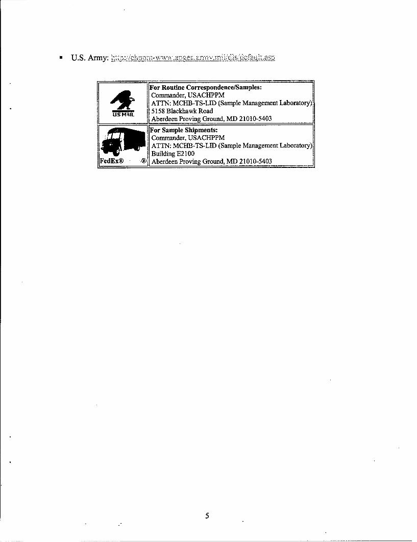
U.S. Army wv
For Routine Correspondence/Samples:4 Commander, USACHPPMATTN: MCHB-TS-LID (Sample Management Laboratory)i
US MIL 518Blackhawk RoadAberdeen Proving Ground, MD 21010-5403
~ For Sample Shipments:Commander, USACHPPMATTN: MCHB-TS-LID (Sample Management Laboratory),
Fed~x®Building E2 100__________91 Aberdeen Proving Ground, MD) 21010-5403

THIS PAGE INTENTIONALLY LEFT BLANK
6

Appendix AMiniVol Field Manual
7

THIS PAGE INTENTIONALLY LEFT BLANK
n n , n i I I I II I I8

4. Institute forE nvironment, Safety, and Occupational HealthRiskAnalysis
FIELD MANUAL
Ambient Monitoring for Particulate Matter
using the
MiniVol TMPortable PM Sampler (v4.2)
Prepared By:
Deployment Environmental SurveillanceAir Force Institute for Environment, Safety andOccupational Health Risk Analysis (AFIERA)
2513 Kennedy Circle Brooks AFB, TX 78235-5123DSN 240-3305; COMM 210-536-3305
March 2000

TABLE OF CONTENTS
PAGE
1.0 BACKGROUND........................................................
2.0 EQUIPMENT, ACCESSORIES AND SUPPLIES ...... ..... 2
3.0 MINIVOLTM OVERVIEW.................................................... 3
3.1 FEATURES ................................................................ 4
4.0 PM SAMPLING PROCEDURES........................................... 6
4.1 PRECALIBRATION ........................................................ 6
4.1.1 Filter/Pre-separator Configuration..................................... 6
4.1.2 Filter Assembly and Impactor Preparation ..... ......................... 7
4.1.3 Filter Handling and Processing.......................................... 8
4.2 CALIBRATION............................................................. 9
4.3 SAMPLING ROUTINE ...................................................... 11
4.3.1 Pre-sampling......................................................... 11
4.3.2 Field Procedures..................................................... 11
4.3.3 Post Sampling.......................................................... 13
4.4 SITING .................................................................... 15
4.5 RECORDKEEPING And REPORTING.................................... .. 16
APPENDICES
A. Field Datasheets
B. Meterological Data Forms
10
1.0 BACKGROUND
This manual was developed as a practical field guide for environmental surveillancepersonnel who will perform monitoring of ambient airborne particulate matter (PM)with the Minivol Tm portable air sampler. The manual provides a basic overview of theinstrument and the ambient PM sampling method, along with a sampling protocol thatguides the operator through sequential, step-by-step monitoring tasks. This manualconsolidates relevant information from EPA sampling methods, the manufacturer'stechnical manual, field studies, lessons learned from previous users, and guidancefrom AFIERA personnel with a background in air contaminant monitoring. The PMambient monitoring process presents numerous opportunities to introduce error. Thisguide was designed to highlight those pitfalls, guide personnel around them, and topromote continuity from sample event to sample event. Additional technical advicemay be needed from AFIERA on occasion; information such as schematics or partnumbers can be obtained from the manufacturer's technical manual provided with theinstrument.
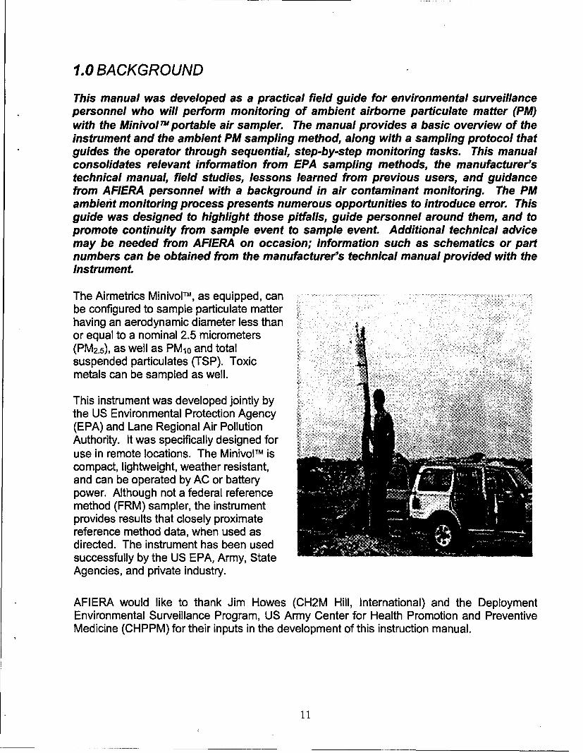
The Airmetrics Minivo TM, as equipped, canbe configured to sample particulate matterhaving an aerodynamic diameter less thanor equal to a nominal 2.5 micrometers(PM 2.5), as well as PM 10 and totalsuspended particulates (TSP). Toxicmetals can be sampled as well.
This instrument was developed jointly bythe US Environmental Protection Agency(EPA) and Lane Regional Air PollutionAuthority. It was specifically designed foruse in remote locations. The MinivolTM iscompact, lightweight, weather resistant,and can be operated by AC or batterypower. Although not a federal referencemethod (FRM) sampler, the instrumentprovides results that closely proximatereference method data, when used asdirected. The instrument has been usedsuccessfully by the US EPA, Army, StateAgencies, and private industry.
AFIERA would like to thank Jim Howes (CH2M Hill, International) and the DeploymentEnvironmental Surveillance Program, US Army Center for Health Promotion and PreventiveMedicine (CHPPM) for their inputs in the development of this instruction manual.
11

2.0 EQUIPMENT, ACCESSORIES AND SUPPLIES
2.1 Each sampler comes equipped with the following items, as viewed left toright in the photograph below:
0 Air Sampler Module w/(2)
Rechargeable Batteries> AC Power Cable> Filter Holder Assemblies (2)> Preseparator Adaptors (2)> Impactor Assemblies
(2 each: PM 2.5 and PM10)> Raincaps (2)> Spare Parts Kit> Manf s Technical Manual
Basic Sampler Package
2.2 In addition, the following items were added with the shipment:
> Bottle, Solvent> Calibrator, BIOS DC-Lite 12K>- Calibration Adaptor> Cleaning Brush> Dropper Bottle (for solvent/grease application)> Filter Cassettes (2, extra)> Filter Cassette Shoe (to open cassettes)> Forceps, Non-Serrated> Gloves, Nitrile, Non-powder> Grease, Glisseal (60g)> Rubber Bands (to secure petri dish covers)> Telescoping Hoisting Pole Assembly> Tripod Pole Support> Utility Wipes, Lint-free> Zip Lock Bags (filter assembly transport/shipping of filters & paperwork)
12
2.3 The following supplies should be acquired locally:
> AA Alkaline Batteries (replace timer battery at 6 months or once/rotation)> Hexane, Unleaded MoGas, Lighter Fluid, or Lantern Gas (grease
solvent/cleaning agent)
3.0 MINIVOL TM OVERVIEW
The MinivoTM portable air sampler is designed to sample at a constant rate of 5 liters perminute for particulate matter (PM2.5, PM1o, and TSP). The filters can subsequently beanalyzed for toxic metals. The Minivol TM can also be used to collect ambient air samples fornon-reactive gas (CO/NOx) analysis. However, the instrument will not be used for thispurpose and is therefore not equipped for this procedure. Disregard those sections in themanufacturer's technical manual regarding gas sampling.
Ambient monitoring is based on EPA sampling protocol, which incorporates stringent QualityControl. Because the method requires precision mass measurement of PM in the micrometerrange, there is very little margin for deviation from the detailed procedures outlined in thismanual. Although there are similarities to industrial hygiene air monitoring, the equipmentand overall process is significantly more involved and tedious. Personnel must take the timeto familiarize themselves with the equipment and the proper monitoring procedures beforeinitiating PM sampling. Pay special attention to the precautions that have been highlighted inblue. The Minivol is essentially a constant flow pump with a number of control and diagnosticfeatures. The primary operational features of the instrument are described below.
Access the control panel by pressing the two release pins on the front of the instrumentcasing simultaneously. Grasp the top cap and lift the pump/control panel assembly out of thePVC casing. One way to accomplish this procedure is by performing the operation whilestanding behind the instrument. The pumplpanel assembly will not lift completely out! Itis attached to the unit by the power line, which is in the form of a phone plug-in jack. Do notgrasp the circuit board. Rest the control panel on the PVC case by slipping the triangularmount stand over the lip of the casing. This is not a firm support, so be careful! Standingthe instrument against a structure can provide additional support, and is highly recommended.
13

3.1 FEATURES
Battery-Operation: The rechargeable, 12-volt lead-acid batteries provide 24 hours ofsampler operation (when fully charged). The U.S. Army has had good success operating thesamplers by battery in SW Asia. Some special notes:
, A green LED on top of the battery illuminates while the battery is charging. The light willturn off to indicate a full charge.
>' A fully discharged battery may require 14-18 hours of recharging. If it is to be usedfrequently, leave it plugged into the charging transformer where it will continue to receive atrickle charge. To prevent damage:> do not store the battery for extended periods while being charged> do not store the battery while
connected to the sampler ELAPSED TE OLWC.°F
The instrument will also operate from an AC TL INIATRLOW FLOW,-
power source by simply connecting the PROGRAMMAE
transformer/recharge cord from the powersource to the battery. In this configuration, INDICATOR
the AC overrides the battery (while it providesa trickle charge to the battery).
> Should the batteries fail to supply sufficient LOW FLOWZINC
voltage (below 10.3 volts), the instrument willADUTMENTshut down. A LOW BATTERY indicator will DUTTON LOW SAT,"EY
illuminate on the control panel if the SAMPLING F.OMRATE
instrument ceases operation for this reason. °
- Connect the battery to the bottom of the RS ',."T.
sampler by inserting the three pins on thesampler into the receptacles on top of the 12V,,ATTRYPOWE
battery (the battery can only fit one way). CONNECTOR MOUNT LAN
14

Lock the side latches.
Programmable Timer: A timer on the control panel can actuate the pump manually, orin the timer mode. The timer can be set up to initiate six separate runs within any period ofup to seven days (normally, the unit will be programmed to make one run over a single periodof 24 hours). The timer is powered separately by the AA alkaline battery located above it. Itis under a constant drain. Replace this battery at 6-month intervals-observe the correctpolarity when installing! Refer to Page 11 of this manual for instructions on turning thesampler on and off, setting the real-time clock, and setting the timer. Practice setting andclearing the timer before attempting to sample for the first time. This feature is probablythe most difficult to fully grasp.
Elapsed Time Totalizer (ETT): Located at the top of the control panel, this featuredisplays the total number of hours the unit has operated. The totalizer accumulates time onlywhen the pump is running. It cannot be reset to zero. Although the manual indicates thetotalizer reads in hundredths of hours, it actually reads in tenths of hours. So there is a six-minute interval between each incremental change. This feature should not be used fortiming purposes. However, ETT readings are to be recorded before and after each runfor QC and troubleshooting purposes.
Constant Flow: The instrument is designed to maintain a constant flow rate despiteincreased resistance, such as from filter loadings. The pump will automatically shut off if theflow rate drops below an established threshold of between 10% and 20% below 5 Ipm (4.5and 4.0 Ipm, respectively). LO_' :OW AJUST and L'CW FOW ZRO adjustmentscrews are located on the front panel. AFIERA has already adjusted this threshold to10%. No further adjustment should be necessary. An indicator labeled TNRESROL onthe front panel will illuminate any time the flow drops below the set threshold. However, thisindicator is used only when making the threshold adjustments as described on Page 15 of thetechnical manual. Don't confuse this with the LOW FLOW indicator, which will illuminateif the pump remains below the threshold for more than a few seconds, initiating prematurepump shut down and an invalid sampling run. When a low flow condition shuts down thesampler, press the RES,.T button on the control panel to restart the sampler.
Flow Adjust: The FLOW ADJjST knob is used to regulate the flow to 5.0 Ipm(actual/ambient conditions) during calibration. Do not deviate from a setting of 5.0 1pm.The PM2.5 and PM10 impactor design requires this actual flow rate for proper particle sizeseparations.
Flow Meter: The flow meter (rotameter) on the control panel is not to be used forcalibration or for recording the flow rate at the end of a run, as indicated in theAirmetrics® technical manual. However, it can be used to aide in identifying flow problems(i.e., troubleshooting). Instrument calibration is discussed in Section 4.2.
Filter Holder/Pre-Separator Assembly: The apparatus shown below can beconfigured three ways to sample for either TSP, PMI10, or PM2.5. It is assembled from left toright in a cascade fashion:
(1) Filter Holder w/Cassette15

(2) Preseparator Adapter W/PM 2.5 Impactor(3) Preseparator Adapter w/PM2o Impactor(4) Rain Hat
A complete assembly is shown in the background. Note that the inlet for the PM10 impactor on theright is larger than the PM2.5 impactor on the left. These impactors easily slide in and out of theadapters by pressing them from their bottom with your thumbs. The impactors must be situatedflush with the tops of the adapters.
4.0 PM SAMPLING PROCEDURES:
Note: New sampling locations require proper siting. Refer to Section 4.4, "SITING" prior toinitial sampling.
4.1 PRECALIBRATION
Note: New Nitrile protective gloves should be worn when handling filters, filter holdersand impactors. Very small artifacts and even body oils can adversely affect results.
4.1.1 Filter/Pre-separator Configuration: Select the appropriate configuration:
PM2.5 - The PM2.5 configuration is shown below. It first requires the filter holder, then thescrew-on adapter with PM 2.5 impactor insert, and finally a slide-on adapter with PM10 impactorinsert. Ensure the impactors are inserted with their tops flush with the tops of the adapters.
PM10 - The PM10 configuration requires the filter holder attached to the screw-on adapter.The PM10 impactor is inserted into the adapter.
TSP - The TSP configuration will not normally be used. However, specially directed surveysmay require this setup when sampling for specific PM species. It requires only the filterholder attached to the screw-on adaptor. No impactors are used.
16

PM 2.5 Configuration PM10 Configuration.
0-RING RAIN HAT201-000 R
PM-0 IMPACTOR JET 2O RAIN FITPM-10 IMPACTOR
STAND OFF (COMPLETE)
TARGET DISK FCT
CAP SCREW MULTIPLE IMPACTOR
i ADAPTER
PM-2.5 IMPACTR.,ET PM-2.5 IMPACTOR - PRESEPARATOR
(COMPLETE) - ADAPTER
IMPACTION CUP PRESEPARATOR ADAPTER
SILICONE GASKET
SILICONE ANTI-TWIST
SGASKET RINGFILTER
ANTI-TWIST RING D IRAIN
" FILTER DISK
DRAIN DISKFOLTER
FILTER HOLDER HOLDER
FEMALE OUICK - EMALEDISCONNECT OEMK
DISCOFN'NECT
4.1.2 Filter Assembly and Impactor Preparation
Initially, and after every two sampling events (recommended for desert conditions), theimpactor targets must be cleaned and re-greased. The cleaning/greasing frequency shouldbe increased or decreased as needed, depending on ambient loadings and degree of soilingobserved on the target disks. Note that the disks easily pull away from the impactor stand-offs.
1. Inspect the 0-rings on the impactor for serviceability. If necessary, use another impactoror replace the 0-rings.
2. The impactors can be cleaned by rinsing from top to bottom with a locally obtainedsolvent; a polyethylene squeeze bottle is recommended. Use a clean soft bristle brush ifnecessary. Hexane is preferred; however, unleaded mogas, lighter fluid, white gas orlantern gas are acceptable solvents. Let air-dry.
IMPACTOR CUP-___
202-102
17
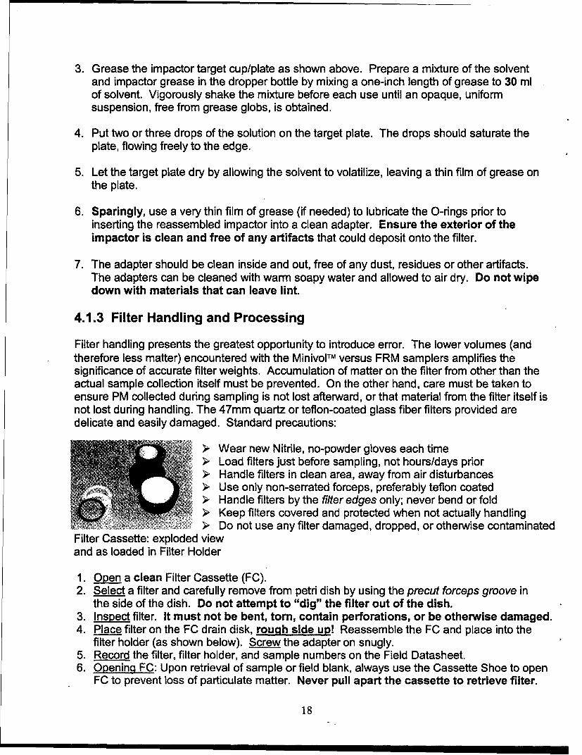
3. Grease the impactor target cup/plate as shown above. Prepare a mixture of the solventand impactor grease in the dropper bottle by mixing a one-inch length of grease to 30 mlof solvent. Vigorously shake the mixture before each use until an opaque, uniformsuspension, free from grease globs, is obtained.
4. Put two or three drops of the solution on the target plate. The drops should saturate theplate, flowing freely to the edge.
5. Let the target plate dry by allowing the solvent to volatilize, leaving a thin film of grease onthe plate.
6. Sparingly, use a very thin film of grease (if needed) to lubricate the O-rings prior toinserting the reassembled impactor into a clean adapter. Ensure the exterior of theimpactor is clean and free of any artifacts that could deposit onto the filter.
7. The adapter should be clean inside and out, free of any dust, residues or other artifacts.The adapters can be cleaned with warm soapy water and allowed to air dry. Do not wipedown with materials that can leave lint.
4.1.3 Filter Handling and Processing
Filter handling presents the greatest opportunity to introduce error. The lower volumes (andtherefore less matter) encountered with the MinivolTM versus FRM samplers amplifies thesignificance of accurate filter weights. Accumulation of matter on the filter from other than theactual sample collection itself must be prevented. On the other hand, care must be taken toensure PM collected during sampling is not lost afterward, or that material from the filter itself isnot lost during handling. The 47mm quartz or teflon-coated glass fiber filters provided aredelicate and easily damaged. Standard precautions:
> Wear new Nitrile, no-powder gloves each time- Load filters just before sampling, not hours/days prior
> Handle filters in clean area, away from air disturbances> Use only non-serrated forceps, preferably teflon coated> Handle filters by the filter edges only; never bend or fold
Keep filters covered and protected when not actually handling>.' Do not use any filter damaged, dropped, or otherwise contaminated
Filter Cassette: exploded viewand as loaded in Filter Holder
1. Open a clean Filter Cassette (FC).2. Select a filter and carefully remove from petri dish by using the precut forceps groove in
the side of the dish. Do not attempt to "dig" the filter out of the dish.3. Inspect filter. It must not be bent, torn, contain perforations, or be otherwise damaged.4. Place filter on the FC drain disk, rough side up! Reassemble the FC and place into the
filter holder (as shown below). Screw the adapter on snugly.5. Record the filter, filter holder, and sample numbers on the Field Datasheet.6. Opening FC: Upon retrieval of sample or field blank, always use the Cassette Shoe to open
FC to prevent loss of particulate matter. Never pull apart the cassette to retrieve filter.
18

Grasp cassette shoe with one hand; use thumb and forefingerof other hand to maintain grip of cassette edges whilesliding, to prevent cassette from flying apart anddisrupting PM deposits. Practice technique before actualsampling.
Field Blanks (FBs): Process one FB for every nine sampling events (unlessinstructed otherwise). FBs are loaded into a clean filter holder with appropriateimpactors and carried to the site in a clean ziplock bag. Momentarily attach tosampler, remove, and immediately bring back to clean process area. Handle andprocess as a normal sampling event-except FB's are not exposed tocalibrations or the 24-hour sampling run. Complete a datasheet for each FB.
Trip Blanks (TBs): Include one completely unused/unopened filter as a trip blank whenshipping sampling filters and field blanks. Ensure it is appropriately labeled "Trip Blank".
Shipping Filters: All samples and blanks should be stored/shipped upright in theiroriginal, appropriately marked petri dishes. Secure dish covers with a rubber band and placein individual 3" x 5" zip lock bags. When shipping, include enough packing material toprevent movement during shipment. Include Field Datasheets and Meteorology Datasheets.Mark box "FRAGILE" and "UPf". Priority mail to appropriate lab as instructed.
4.2 CALIBRATION
Calibrate the instrument to sample at 5 liters per minute in the field (actualconditions) prior to all sampling runs. Because air density does not affect theflow rate readings of the BIOS TM flow meter (vs. rotameter), no corrections arerequired to ensure 5 pm, actual conditions. Varying air densities also are not asignificant factor in toxicological exposures to PM, so unlike gaseouspollutants, the EPA requires no STP corrections for particulate matter sampleresults (however, meteorological conditions will still need to be recorded foreach sampling event).
Airmetrics typically supplies a calibration curve for the instrument's rotameter.The company also sells a digital manometer that reads in static pressure, and ablue calibration orifice with a calibration curve and associated equations forconversions and corrections. These will not be necessary for calibrations or forcalculating final flow rates. These procedures have been greatly simplified bythe application of a BIOSTM DryCal® flow meter-a field-portable primary flowstandard that provides direct calibrations in Ipm. The Airmetrics' bluecalibration orifice has been modified to interface with, and act as the instrumentadapter for, the BIOS M flow meter.
19
Operational Check: Prior to each sampling run, theinstrument should be checked out for leaks andgiven an initial calibration in a clean area. This willconfirm the sampler is performing properly and willreduce any "tweaking" needed when calibrating inthe field. Follow the procedures below.
> Setup: Ensure sampling filter and appropriateimpactors (greased) are in place. The hose to thecalibrator should be attached to the bottom port. Inspectfor kinks in the lines or any other obstruction in thecalibration train.
> Leak Test: Upon train setup:
Press the calibrators ON button.Press ONIAUTOIOFF on the Minivol's control panel to
manually turn on the pump. Check for any restrictions. ,.Place your thumb or other seal over the open end of the
calibrator's intake. The sampler should stop operatingwithin 5-10 seconds. If it does not, check the seal and, ifnecessary, the sampling train for leaks. To isolate leaks,disassemble the train at each connection, starting withthe calibrator, and perform a leak check at each step asyou work your way back. Example: pull the hose off theBIOS calibrator and seal the hose opening. Restart thesampler. If the leak check passes, the problem is thehose/calibrator connection or the calibrator itself. If itfails, continue moving through the train, sealing off eachconnection until you isolate the leak.
Calibration Procedure: You should familiarize yourselfwith the BIOS DryCal DC-Lite calibrator (starting on page 5 of the calibrator instructionbrochure provided). Once the leak testpasses:
1. Press the "READ" button on the BIOS TM
calibrator to read the sampling rate in Ipm(observe the FLOW, not the AVERAGE).The ":EAO' button must be pushed onceeach time to observe an instantaneous flowreading (or, press and hold the button toiniate the "AUTO" mode, which provides anew reading every few seconds).
2. Adjust sampler flow rate by turning the
FLOW .ADJUST knob on the sampler
20
control panel. Adjust to 5 Ipm +/- 2% (+/- 0.1 Ipm). This equates to an acceptable rangeof 4.90 - 5.10 Ipm. Disregard the indicated rotameter reading.
3. Once individual readings indicate 5 Ipm (+/- 0.1 Imp), press the "READ" button 10consecutive times (or allow the "AUTO" mode to sequence through 10 readings). Observethe average for all 10 readings. If the average is within the acceptable range, calibration issuccessful.
4. For official field calibrations, record the average as the initial flow rate. If the average isoutside the threshold, readjust the flow rate accordingly until the average of 10 consecutivereadings is within 4.9 - 5.1 Ipm.
4.3 SAMPLING ROUTINE
24-hour sampling runs will generally be conducted at 6-day intervals. AFIERA will provideinstructions regarding any changes to sampling routine.
4.3.1 Pre-sampling
If the sampler is to be operated by battery, the Minivol battery must be fully charged prior tosampling. The calibrator should also be charged. Once the instrument passes the operationaland calibration checks in a clean area:
1. Record preliminary information on the Field Datasheet (i.e., date, location, sample no., etc.).
2. Detach calibration train and the filter assembly from the sampler.
3. Place filter/impactor assembly in a clean plastic bag (e.g., zip lock) with a clean rain cap.
4. Reinsert control panel into the instrument housing for transport.
5. Transport filter/impactor assembly and calibration train in a suitable protective carrier, e.g.,carrier cases that accompanied the new instrument. Brbg Field Datasheet.
4.3.2 Field Procedures
At field location, carry out the steps below before sampling. Procedures should be performedin an area relatively free from the elements. If necessary, carry them out within a vehicle.
Remove control panel from instrument housing. Do not detach power cord. Grasp unit bytop cap, not circuit board; place panel on lip edge, and support against wall/structure.
Attach filter/impactor assembly and calibration train to the instrument.
Start pump by pressing the CO.A2T 2Z- button on the control panel.
Leak check sampler.
Calibrate to 5 1pm +/- 2% (avg. over ten consecutive readings) under ambient conditions
Record average (AVG) flow rate on the Field Datasheet.
21
Turn off sampler, record reading from Elapsed Time Totalizer LED (next to AA battery).
Set Real Time Clock (if necessary): Personnel should LCD DISPLAYsynchronize their watch with the instrument clock.
PRGRMMBL T iI MER o,
* DAY SET: While holding down CLOCK button, pressWEEK button until correct day appears at top. 11 : 0?
* TIME SET (Hour): Hold down CLOCK and pressROURI O AUTO OFFuntil display indicates correct hour (you may need to cycle Im " f' ""i "=/="
through hours to obtain proper AMIPM). 0( (- D C)* TIME SET (Minutes): Hold down CLOCK and press 0 (D 0 0
until the display indicates correct minutes. Seconds willautomatically reset to zero.
Set Timer: (It is recommended that the timer be set up atZ ON/AUTO/OFFthe field location) BUTTON
9.1 Set new onloff times.
9.1.1 Press PROG once. on will appear in the lower left comer.
9.1.2 Press HOUR and MIN to set desired start time. Note the correct AMIPM.
9.1.3 Press WEEK to select day of the week (i.e., Mo, Tu, We, Th, Fr, Sa or Su). Whenmore than one day is displayed, these days will all have the same power-on time.
9.1.4 Once the program-on time is set for the first cycle, Press PROG again to setprogram-off. lo will now appear. Again Press HOUR, MIN, and WEEK buttons insequence to set those parameters and complete the first cycle. Note the correctAMIPM.
Normally, only one cycle will be necessary. All subsequent cycles (2 - 6) should be clear.
9.2 Clear unwanted entries.
9.2.1 Once Cycle I is set up, press PROG to toggle through each of the remaining cycles (2- 6). If a start or stop time is observed in these cycles, press RESET once to clear theentry (a cleared entry is signified by four dashes in place of the time). (Note:Pressing the RESET button again will recall, or reinsert the time just cleared!)
9.2.2 Verify correct program entries for all 12 entry locations by pressing PROS to togglethrough the 6 on/off cycles.
Your entries for cycle 1 should look similar to the following example:
22
8:00 00
,on
AM Tu
8:00 00
loff
Press CLOZ to return to the real-time clock display.
11. Press , AUT F button until the bar on the lower edge of the display is above the
"AUTO" legend. The timer is now set.
12. Reinsert Control Panel into the instrument housing. The instrument is now ready tosample. (Placement/mounting instructions can be found in Section 4.4, SITING)
4.3.3 Post-sampling
Potential for change in sample mass due to particle loss, passive PM deposition, anddamage to the filter increases between end of sample run and processing of filter. Therefore,personnel should arrive at the sample location before the end of the sample run sothat the filter can be processed immediately after sampling. At the completion of thesampling run:
1. Remove sampler from mounting pole to a relatively clean, nearby area out of theelements. Maintain the sampler/filter assembly in an upright position at all times. Placeon a firm, level surface.
2. Gently lift pump/timer assembly out of the unit and mount on the edge of the housing,preferably against a support structure such as a wall.
23
3. Check control panel for the Error Conditions below. Either condition results in prematurepump shutdown. If an error condition exists, refer to the "Error Conditions" discussion atthe end of this section for troubleshooting assistance.
" LOW FLOW Indicator" LOW BATTERY Indicator
4. Verify elapsed time as shown on the Elapsed Time Totalizer at the top of the controlpanel to validate sampling event. If the time lapse is less than 24 hours, refer to the "ErrorConditions" discussion at the end of this section.
5. Verify correct time and day on the time LCD to validate sampling event.
6. Record ending flow rate on Field Datasheet: remove rain cap, attach calibration train, andpress ON/AUTOIOFF twice to start pump. Record the average (AVG) of 10 consecutivereadings.
7. Detach Filter Assembly and carefully place into a clean zip lock bag for transport to filterprocessing area (clean area). Every attempt should be made to keep the assembly inan upright position throughout the handling, transportation, and processing steps.
Filter Recovery
8. In a clean area, carefully remove filter and place in appropriately numbered petri dish,rough side up. Close the dish immediately and secure with rubber band. Store upright.Refer to Section 4.1.3, "Filter Handling", for handling procedures, precautions, andpacking/shipping instructions.
9. Complete Field Datasheet and Meteorological Records as described in section 4.5,"RECORDKEEPING".
10. Prepare for the next sampling event. Refer back to section 4.1.2, "Filter Assembly andImpactor Preparation" to prepare for the next sampling event.
24

Error Conditions
LOW BATTERY Indicator ON
Observe the total elapsed sampling time (Elapsed Time Totalizer) to determine the length ofthe sampling run before the sampler turned off. If the sampler operated for at least a fewhours of time, the likely problem is the battery was not fully charged. Switch to the fullycharged backup battery to complete the scheduled sampling event while recharging the firstbattery according to the manual's directions. If the second sampling attempt is successful, trythe first battery again for a 24-hour period, this time in or near the office/lab area. If theproblem reoccurs, the battery is defective and will need to be replaced. If both batteries havesimilar problems, it could be the AC source, or the instrument's pump is operating at anabnormally high rate throughout the sampling period to compensate for a restrictionsomewhere in the sampling chain. One other problem could be a pump that is drawing anabnormal amount of current. Determining whether the source of the problem is the batterypower or the sampler can be accomplished by trying the batteries out in another sampler.
LOW FLOW Indicator ON
Do not confuse this indicator light with the THRESH indicator light, which normally lightswhenever the sampler is attached to a power source but is not operating.
Observe the total elapsed sampling time. If the battery is O.K., the problem may be due to anAir Restriction in the impactor inlets, filter holder (e.g., overloading of filter, wet filter, etc.), ortubing (crimps). Loose or broken tubing on the outlet side of the pump could also cause alow flow condition.). A Pump Malfunction could result in a low flow condition, which isusually caused by damaged or contaminated pump head components (valves, diaphragms).Determining whether the problem is within the filter assembly or the sampler can beaccomplished by operating the sampler with the assembly both connected and disconnected.For pump maintenance instructions, see Section 7 of the manufacturer's technical manual.
Overriding Low BatterylLow Flow Indicators
When these indicator lights are on, pressing the RESET button on the control panel canrestart the instrument. Pressing and holding the switch provides continuos override of thefault circuit, when needed to troubleshoot the instrument.
Additional Troubleshooting
Other problems that can be encountered and their corrective actions can be found in Section8, page 57 of the manufacturer's technical manual.
25

4.4 SITING
Do not site the instrument adjacent to obvious air emission sources, such asindustrial processes, generators, fueling and fuel storage areas, vehicle oraircraft maintenance and operating areas, any type of stack or vent, refuse orother waste sites, etc.
Do site the instrument:
at or near the center of the base population> in an area that provides easy access and security from tampering> in a relatively open area in which nearby buildings/structures do not impede natural air flow> with the air inlet at a height above the ground between 2 - 15 meters (6.5 - 49 ft)> with the air inlet at a height above the supporting surface of 2.0 m +/- 0.2 m (6 - 7 ft)> with the air inlet at least 1 m (3.25 ft) away from the nearest wall, structure, or other
obstacle to air flow (preferably much more)
Low-story roofs often provide an adequate measure of security and representative
monitoring. The sampler inlet must be above the height of any wall or barrier surrounding the
area.
Obtain GIS coordinates of the site. Ask a local GIS-equipped unit to provide assistance.
Sample Latitude and Longitude in both degrees and minutes. This information is required on
PM Sampling Datasheets. Note: Check to ensure that accuracy of GIS does not make
coordinates classified.
26

Additional Precautions:
The pole will likely require additional support in areas susceptible to high winds/tip-over* Mounting brackets are located on the bottom of each tripod leg, along with screws, to
secure the tripod to the roof or appropriate surface once adequate siting isaccomplished; bracing with rope or other means of support may also be considered
)o The top of the inlet must remain horizontal during sampling; ensure the pole isstraight and, if necessary, use tape to stabilize the sampler against the pole
4.5 RECORDKEEPING And REPORTING
4.5.1 Field Datasheet
Complete a Field Datasheet for each sample and field blank (not trip blank). Review
the sheets for completion before forwarding. The original datasheets will be placed in
zip lock bags, packaged with the associated samples, and forwarded to the supporting
lab, which may be CHPPM or AFIERA. Retain a copy on site and mail another copy to:
Deployment Environmental Surveillance
AFIERAIRSEW
2513 Kennedy Circle, Bldg. 180
Brooks AFB, TX 78235-5123
27

Field Datasheet - PM Sampling
Instructions
Preliminary Data
Installation: Self explanatory. Base Code: PSAB: 1242 / Al Jaber: 1237 Esk Village: 1235Site Location: Describe area, e.g., "Building 28, barracks rooftop."Geolocation: Original siting measurements. Provide Degrees and Minutes.Date: Sampling start date.Sample ID#: Dependent upon analytical support lab:
For CHPPM: XXX YYYY DDDDD ZZ" XXX - First three letters of base/installation" YYYY - Method type (PM10 or PM25)" DDDDD - Jday code: last two digits of year and three digit Julian day (e.g., 00030 for 30
Jan 00)" ZZ- Sample type: P-Primary sample; C-Collocated sample; FB-Field Blank; TB-Trip Blank
For AFIERA: XX XX XXXX" First two digits: EX• Second two digits: Sample Year (00 for SY 2000)* Last four digits: Numerically sequenced sample number for that base during the
calendar year.The AFIERA Lab will also require AF Form 2750 (3 samples perform) in placeof
the Field Datasheet. However, completion of the Field Datasheet is still requiredand must be forwarded to AFIERA/RSEWDeployment EnvironmentalSurveillance.
Sample Type: Circle one-except for metals. Metals are sampled/analyzed in conjunction withPM1 0, PM2.5, or TSP. Circle "Metals" and the appropriate PM type.
Filter ID#: Fill in with pre-assigned numbers which accompany the filters from support Lab.Instrument SN: MiniVol serial number.Calibrator ModlSN: Calibrator model and serial number.Filter Assembly ID#: Fill in with pre-assigned numbers from AFIERA DES.
Operator: Sampler's name.Contact Info: Sampler's E-mail address and Telephone number.Signature: Sampler's signature.
28

Field Data
Pre-Sample
Leak Check: Fill in block with Pass upon successfully completing leak check. If failure at start,fix problem before initiating sampling.
Starting Flow Rate: Calibrated flow rate, i.e., 50OOmI/min +/- 1 OOmL (avg of 10 consecutivereadings).
Sample Start Time: Normally the start time programmed into the timer, if used.El. Time Totalizer: Record start reading from control panel after calibration.
Post Sample
Leak Check: If leak is identified within the sampler or the attached filter/impactor assembly-sample is invalid. If the leak is identified within calibration train-fix and re-test.
Ending Flow Rate: Post-sampling flow rate (average over 10 readings).
Sample Stop Time: Self explanatory.
El. Time Totalizer: Record End reading upon completion of sampling event-but before measuring
ending flow rate. A valid sample time is between 23 and 25 hours.
Average Flow Rate: Average of Starting and Ending flow rates.Total Sample Time: Record in Minutes. (e.g., 24 hrs x 60 min = 1440) Valid sample is 23 - 25 hours.
Do not use the Elapsed Timer Totalizer readings for this.Actual Volume, Vact: Multiply the average flow rate (Qact) x Minutes sampled.
Background Notes: Include any information that could affect sampling results for this sample.Notable activities would include increased aircraft/ vehicle operations, orother combustion processes in the area during the sampling, significantwind-blown dust events, or any activity or event that could affect airborneparticulate matter concentrations. Include any unusual circumstances andany other helpful information associated with the sample or sample period.
Lab Analysis To be completed by CHPPM or AFIERA, depending on support lab.
4.5.2 AF Form 2750
Only when the supporting analytical lab will be AFIERA, an AF Form 2750 (3 samples per form)will also need to be accomplished and forwarded along with the samples. In this situation, mailthe ori2inal Field Datasheet to AFIERA/RSEW Deployment Environmental Surveillance andmaintain a copy of each form. CHPPM lab requires only the original Field Datasheet with thesamples-no Form 2750 is required. Mail a Field Datasheet copy to AFIERA/RSEWDeployment Environmental Surveillance and retain a copy.
29

4.5.3 Meteorological Data
Record the Meteorological Data for the beginning of the sampling period and at eight-hourintervals during the sampling event for a total of four readings. Include your observationsover the event regarding visible emissions or odors. Meteorological information can beobtained from the local supporting Weather Station.
30

Appendix B
SUMMA Canister Sampling for Ambient VOCs - (TO 14A)
31

Excerpt Taken from USA CHPPM DRAFT TG-251APPENDIX 6-4
AMBIENT AIR VOLATILE ORGANIC COMPOUND (VOC) SUMMACANISTER SAMPLING (TO-14A)
AllicaitScienti.&* is a sejhiiwrud xtdrw fAc'S~njkInc. Tu~con. A: ziina
%,41;,Jm (taup
6-4.4 REPLACING; THlE FRIT PARTIULATE FILTER
Pofor~i th~ .- Iwnz 4 in. u cle s= eufvitotmwt &at is piourord firvo tuw %eithei. If jwsbl,w~i ibiint die i idowmgl~ or. d CleuI. lekdA SUffu
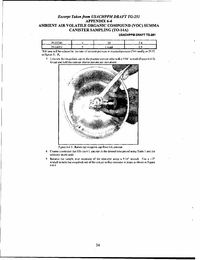
I. Rozmwe. the -swurlpIe inuie1 exLwflji~ fjoi dw flow caiitroll it~h a~ ;.16" w y:ich If t6-ssw ageak, niut wn the ojutx; wico twus vvith zhe nut on die wnp~ir-~ exterium~ oiitlkitp:~up uaj hole 1: wsth .4 1 'T' ureuch
32

Excerpt Taken from USA CHPPM DRA4FT TG-251APPENDIX 6-4
AMBIENT AIR VOLATILE ORGANIC COMPOUND (VOC) SUMMACANISTER SAMPLING (TO-14A) bRF 65
2. Ritiv flie oli C-Rm,,, and tit rdwi hy turnitu Lhe rest.cto: upside&) atid l~ht.t1p.nl it i
3 Rqlau thu ian filwi i*nd nta~wfh%, ou; wang a pui of £l~'Jn Wx ~~tc r~conwinimior Do noti kgrndL h filiw oi; G-un-u Withr. iasilzut Thx flit is~~:~cfir~l. thten flie C-rawn. (fignuo 6-4.2).
Fagputa 6.4-2 lnstaliatioz of til file: and ( ri' into flov coiroltel
4 Replace thte qxrppe mlet etumrsior Tighter the swagdock inut u.nfilf irminv a but dlo wctol ett uhIer if tho fajgloe nut an th! orifice tat"r~ witht tli. ru nt i e nilel, gixj andhold to withi a 2 wranch.
5 D.Liz4ud dusw-d fht fito~ Th-e 0f).; nmay bi uetied i.fict demr- it with watci± wid
6-4.5 CALISRATING TIlt REMTICTOR FLOW R.ATE AND L EAK ('HECKI Pefolimn thie lbllowing Mup'. ir a ean eirv amnien dial 3, pwtf-wzd from ifr. wranbh-i.
2 ose thw cn~icai orifictes co&e located on 6ci top q%,vt!e.o0C nti tein to Tabb 64-1 :'hthe M~l uinie- and taxge: flov. =Ln±, fio a 6 L nsi
Tab~e o.Fill Tine an d Txzel Flm% Rate, ivr a 6 L ('wmstef __________
CaitkJ Onft~ PN SI~mp.~ Fil Tiurn for a~ 6L f____________ ________S_____Cod Caniiitr_ (iourn) _______Flow__________u
39-2301O 86_______I____________
39-2.1030 2 3 27
________________ 3:F 7 - (W
33
Excerpt Taken from USA CHPPM DRAFT TG-251APPENDIX 6-4
AMBIENT AIR VOLATILE ORGANIC COMPOUND (VOC) SUMMACANISTER SAMPLING (TO-14A)
USACHPPM DRAFT TO-261
3q-23240 I - 24 1 IJ1-14.)10 I u kI..
FEi unne will IV feduzed h.% z"w I ru ii (it' x pn!e sw vo "id p.-Lsiwe (76 irl mIg oi 2It Iig) P, P
(i±pxidhojld the c~r.ute net to pziwNeu as: ivkwonsel.
4 (tamser a tei~trickii t~a fills the 6 L c=vsw in the dewerd urnw. peziod1 wing Tuable I wd .h
5 RemoviLe the. wJU l et 4 enwaon of$ the rest ncto! uilniv w 9:6 wrech ~uIls'e a u2%u~ tad o E30 It th'! s waIoc k Iut of 0 1- l cLa C;ernftm::: m l~ctor In r p.1e Elumv In Figu.6.44
34

Excerpt Taken from USA CHPPM DRAFT TG-251APPENDIX 6-4
AMBIENT AIR VOLATILE ORGANIC COMPOUND (VOC) SUIMMACANISTER SAMPLING (TO-14A)
6 Coxiczt the :eszractm outlet u) tite uudel of the eiv-cuated pjjc cw4. o s oi ai fn :6-4 5 Cis-) the =11.ito xnlt iwtdi a Ila Mwid Whie ughter2ig the zenut or. the
I~Mi~t1l uit t~iliittl ~it~Dk not overt wthten the st ce:;k nt
LLFiure b-435 A~tuilii tint reuicwr wu muster
7 ('oxie;.t the otxht-e ofti-j Ahcaflo dLn eck dev ice Wa Ole zde: oftf e rei~nctor i~s,.mkin i
figure 6-4.6. The atiunx or 6w, Aiucax dev ice s houd i pr~ntitg to r tlielit: mkagp-1ock oil th.- ole: , te ~z: writ .1 rh until fun sn~vug If
the oaeeock not (n th.e iki of he :uc'.r w %with the q%%4zeloc nut onj thte omt~etthe A'kat, gnrs&P :he ieoek nut tin flte restnctor mlzt %vwh au 12" %miich xid hold.
35

Excerpt Taken from USA CHPPM DRAFT TG-251APPENDIX 6-4
AMBIENT AIR VOLATILE ORGANIC COMPOUND (VOC) SUMMACANISTER SAMPLING (TO-14A)
USACHPPM DRAFT TG-251
Fiffljeb-4. (lnnuctig Alicat flow &=~L demce to~ Cktv restictor
9 Ness the~ ze- balum o the t ,we or thi- Ahczt uv:iL a zert.o & dz;paed mi tltc chdii f ej10 (4-len tIsw catiifZLe %alve wuid watt 3')ad oiiv : uri1 Ov flov ,wtbItzex
I1 (I C- t thw ilet ofthe Ajz wil td~ w st~ u~ois ip1~vtd oni the dj-jJ licrzera)12 (,Cl~the c~sfcl 4%: dt w: 5
13 Vncovt fle ile: of ih. Aliteni If the f~ow fi0lo ic t.At. a lek exzs4 i flow path.(Cireu1v lcer.'= the s.viagzekt L iti and tepra! sirps 1 thittgl 14 witd theiw Wia nolex~ak,; d
14 Ope:a th;: "c;ui~e a emd walit 30 -eeod-ix orU mthe flow mabi~us15 Rititove tie out.: ;xot.-cvc scie%% kioatad w. th-. Ierwi oftb fl tom nvsicttw'ts fixe uiini
thr 11" hex kLv As 4KAz in. F31,gut; 6-4 7 1v ficit set sc:c% u- iti~d ~ this
36

Excerpt Taken from USA CHPPM DRA4FT TG-251APPENDIX 6-4
AMBIENT AIR VOLATILE ORGANIC COMPOUND (VOC) SUJMMACANISTER SAMPLING (T-14A)
FEputo 164 7. Rmv:pt~otivt ovwer Im fluo. sia aew
1l mdlus. ut so soe%% Ai~th 1 1" hex~ kx-% witd 11th flowta. us~ trw In ihAii sak cl; W. N~.sabte ki th~e~ ffl rt imed in Table 6-4-1 (ii the uwiip~id
co&e otn the~ msiji. ge diua~am hu4ot). DO NOT twu flt! i siL.. itu d 3 txns.The :-nu-mal Lbavxrawr1 ca-i be Laaud lyn overLo -teu.-v
37

Excerpt Taken from USA CHPPM DRAFT TG-251.APPENDIX 6-4
AMBIENT AIR VOLATILE ORGANIC COMPOUND (VOC) SUIMMACANISTER SAMPLING (T-14A)
q 1 1111P UI(Mt I I U=AWt
17 WLLI 31) scond,, WiLJ dt th1s rate IWbtLiZC..18 Rv-;ozd the nieasurd tlctk rige it cultic entfavters 1;et nitnuj (wt)) md the s.erial nrnxhtr
ol the II ii aC. Xnrfll &~t;I,4tt:Ct.
l') (Ckmc thec viuctie c:uicstefs alle: valve andt~IAx to P~ewl en xp.2 0 Reoplace oiie outei uxtcar c~wo taw flov rest:xcn5cs t*=O Wid ten111 Intl fitszdl.1%~z21 1 t:hxe aelvwk rit on th;. ox:e ofthdi Aliclu And r-me it
22 1 Ies :e -,,uwikoc . on ill. ozJ-e-t of the- resL to: c1 xi erkive it23 Rmexaldl tilt .urpkt~~e exteltsion on the remucwt Tqnzhten te c nnettzt.- sl~jalock nut
on ie sairw i alxde~le. ~ei~c~ until fttho'N sswgoI.
24 Replulc- t1v bkxcL pli-aic cap n the %a.lt2e -4ie: extalmonl25 Store dl,. flowm rest:cto. Ill a plasic Itag or wxxn altuhram~utit tbAimunit rx-ady fo. ld: ufit
to ;Isevent1 couit~ianx26 Italizat tlhe alx2 iv e s Amo the eaih, ofthe re-wunnxi flow Iic'mrs27 Rqe~i. the swvagt4ck c:4) w the, p~wtice c-auster aid. ig taltinl fift-n1 xcgx whena
itihed Do nlot o.el tighiten nnd uvo;C fOii thqd "IiLSA" iil"t VWtId tiiihtcitiig 9wmt lweloekL Cap
NOTE IF' the I forin~c prxLsur di-ts fiuzu xmdad esoit ions (760 irmi lig or 29.92 tIn 1g)tcnfiwxtv thaiiple prxod (it fltm late wII have to be: rnodxt&fd to Pineven: pritxnawre fihulgo
the cutwqer ta caiintei v h I Leto v.icuun: i meazeed atmiisphenex pre~uxw'eid I-, to he ci~exuet.Thxai nf t-pelmhI tru~e :11 mox t~unou' wew withf high elevatioxis Ellixe: OIL- 4.2iplu
period ,it the tunplu flov. nac m t niee to be rehard b% a rzctos of P.4,P, %o.ier.- P. Is the aveiag-ambient baroirte tsxue .uid P, is the psemIliuia swdtldax co-ditwons For exznp~h. if &he
ae art-bltut bnzo.mett:4C illessre 1, 6,0 ram 11g. eithet thlt fl1ow will twed u) ixe tvduced or J.waritpie riod, vill need to h;. xettted b, 650.760 , 0 85. Erivie &we target floot ratit the samrxll.eriod w~ould thell be mrntqhplie bA 0 85 Ifwlo~mblc. the cait slto'ad be lioitored duunge tilesatnisiec ezn, to provenit thent frlt rad 0 Vacuur1t r a lltASeriC preSS.C
6-4.6 PRESAMPLIN(. PROCIEDURESI P.-ao it toasounane the cannutei, pe.116--i the "Ib~iw-mg sleps sit a chzir. rnviwinimt tha: is
2 (zaoose, the flow vetttistot thai wdit 1W the 6 L caliker II te dtise:ed Ltne p2!vod. Cauibrwtit!e estrictor tiay & t' tpsrx. Sectiont 64 6, -lotilmte ar l-l vede- Ont te0 top mwwte ick
ra U:lte : muiczol's Il.3 R-inov thle N%%ge cap fton the samwple Gaatnl .p id hold tue car.-xler ittdet witll a
ficte hand antido& rot tllow the itule: to move.4 Rerkove ther Umov trWm haul the rw~ettve plaoic lag (ti alulturiumr ib.i5 (krauaec:, thle outlet 0 ' the resvictor to the inlet or thlt 6 L ityae cr:e.Tighten the
mmlywkliJ nut on the lreirct outle un. titlN in~ug If the. canomte intlet tufls with thletaut oil thX outlet of &he aeta ieltc. mis~ad hald It mith a fiae lucd Do not over tighteit
38

Excerpt Taken from USA CHPPM DRAFT TG-251APPENDIX 6-4
AMBIENT AIR VOLATILE ORGANIC COMPOUND (VOC) SUMMACANISTER SAMPLING (TO-14A)
USACHPPM DRAFT TG-291
6 Cnokxe a ir u ste diar u311E jprrpeaKiy the conter.:, of VCs in die wIhien: air.Nomialiv a saunpiznr iocitio wJill not hL- -- n close to a rrollutan i sow:e. ba: a cortwn
tjaea i nor u)e~1 aisxe3s the ambietan in the \aelnity" of the sinac7 Remov~e d'e black ~ap fromn the santple ir i Pan' ae In 6ie proWa=%v plaiebc o:
In the atinurtrl fo;d (dona't lwo c it)
8 Open dn. cwwttete ]life. vahve A'l %av. then turr w:l ba wk.
9 ltco: d .eie I r, t a] e it u dvisoI a-vd on *"e % ou itin atr in th e dat~iA :v.re10 MNfon: die curnset so that the &.izne rilr a heig~ht of app; irnuie)v t) ftesln the
jpround (IC 1:1 the blem.lrng Zone), n-' odieiwse spnrified Thr ste shouid gnerah v lita cmauain hame from obsauclesa uh is bu'dizix (it tie~to avoid '..i ta~bt-eia~e gen.-:aleeby then. If no inoarling hjda us a:dizhle the mmutisr mrrv be pltwod on u levelholituona .5fce dut-Ig dwe sxaaple event It' iaul is erqiected to occer durmt'g tersi
e~et~ s.~1 th saniple inlet extersior. sto that a: ",11 siaxra div.11 Sh~cd dte canikte: fioni direct swauuh~t us;Ing ai 4teet of ca.dthoad, for exam i!,. Direct
sunfight ~eic it, t dwscrt iminimfleit) wi1 hewt the xi wo~ected inside th. L.Laletalx)%e the irnn trinper-exxe, therehy redacing die p~reddtferencee between fic=qiser and uhe Iihmmuino hee Th ,s resa;j.a' In u :edictioi in the ti oa liunr of W:acoliczed and wit] nisl pr nraturte tfihng of the eani~tvea
12 Record the ealkiw"ne inforanur ir. the. tda'a shee:-. lntaI vcwir Xize z dArn ; Tht: vacutir eaucze sho~jd disp~v rl riu aatnv2
-Anaien: tunneniuinc (%1ejAuiz the antbiaral tenuerauie of the at- ov~ty fiont direct
- Wwtr 5 tinies and record the nhne:!xretr tvesure dispkved tin thep ;xuinbhararetet
- htttaI Ml.w ru~e fioar: the cuihtaion praeeduxe- Sumple date
- hriaI &tW tin%--Naine of the i&ing location, inct udaag thw fIbiowing-Countiv
- MGRS Location (10 dgnti)C amnteeria number
-Flow rasnctol, %=rd nuabr-(utictit %weather vin utjn :=. any ofte relevxit infoine-ton tn the .- ns e~nof ,]I.- data sheet. Th&. location of ncarhA wturces or Npolutng =htites slamdd alqso he
wcr. i !hc d=~rhe6-4.' POST SAMPLING PROCED1 ."RES
I wrenove th. =aistei fovn Ahere at was~ mounted
2Rcuord dii: final vacutti gaut readling II the dua she.t If the emnstet v:cuint ills reache-dle&s flh, - I ali II h: the santple periodi ,n" noed to w- shortened or the flo&we rite tdtced
3 Clo4,L the cat-4el ia."et vah 2 tiuht.
39
Excerpt Taken from USA CHPPM DRAFT TG-251APPENDIX 6-4
AMBIENT MIR VOLATILE ORGANIC COMPOUND (VOC) SUMMACANISTER SAMPLING (TO-14A)
USACHPPM DRAFT TG42SI
4 Rep-ace tiue black, ; last cap (ii the saxnltle attic: extcwitm5 R Ceo:d tile flallownj±mf waitiun in tiIt. 61a hc:
-Atibiev., Tentperaure (\leiusie dIe! amnbint ttipetlaur of tile uit aauav fixont direct
-Wtt 5 rzanuls andu:cozd the anoshezcprsswc di-svlayed or. the- pornuhd buaoutwan- uaieliutiaiet couittorr (it, reurs ecatn)-At: ativ~e :klrtol oa ewbN I i: reinw-ks xenonm)
6 Iet fi'61 Ote 1 61l6A114p Steps it a Cle2u ZLet protected (-oan the weather.7 tn% w !*he v%auelocL nut a: the outlet oFthe flami resfto with, a 9 16" wrench to reano
it buitl tile canastel tr~et. bithe camstle: fillet twins Wil tht. sw-aw t t i :he aestawun'soutlet, gn-..p wid hold a wndt a lice hand
S Sciv die:' v~ajpelocL Cap ott tle eun"' ret id 60titem %fih a 9 16' viench until fairlyszaut (' uip rid hld the- eanistel title to prew l fit ni ti:t Do nwo OW tzpbenrj.
9 Race Ot flow tetietot an1 a seal.l plumts hag, ii %lap sit alurlwin lot, to presentCOUL1iratr
I1o Simc the canists in a aeno mrul shipznat
6-4.8 MNU2A51:RINC FIAL RLSTRJ(TOR FLOWI Peatbuthe A Iilo"Ing steps in. a cleai urvaaonitten: tIa-!jt iouxntcd front tit. %,neruthar2I Remove fte esuacun tion its pnncetaw bug, or ahuainiwi fbi!3 Attac'h tse ietrcor ut dit;. pnu.-ue cauasta as descathed fin (ALIBRATINC THlE MO(W
RESTRICTOR4 Rctnc theiA. -cu d tal e~tnsmon5 (?aac h ~:to the iniletoti ofdw ow-eeto6 ILurn oil tIhe A'lzjl
7 Presis the Lan' huttin oon the ftort face until a zeto is implaved on. the digital wcrezt. Thea.OWeimbl kshou.look 1iLe theCoiowiplae.
40

Excerpt Taken from USA CHPPM DRA4FT TG-251APPENDIX 6-4
AMBIENT AIR VOLATILE ORGANIC COMPOUND (VOC) SUIMMACANISTER SAMPLING (TO-14A)
8 Opiw flt: ptactizv cmtf uil~ vaiv. W1l ieVA MA- N ,t' - tha±e %a.'iwi u !aJ~q aitjux;* 5 an1 He
9 Covat the 11le0 01 tlii.]- AI~ 11t! the! 110 fkChLS'4t0.
10 ('h,. the czqwi ittlet vaih. nd %kut 5 ttanuirs.
Ii I I orw% uie &hea tl If th.- fioiA tate iaft~ums ze thiee 1,, t IvAi In the swar.~ bi'pecttot IeA. xid tiIthln an Iose swapehiei. Rqpet step; 7 8arc'ugh 1C0un wii tic)h. aredectected
1 2 Opena 0Iw e=ansti Iulet %.ahe and Ul the raw. rate &ipa4ved on the Aleuz to h% ubte..
13 Rewd lhe fmI flow ai1.± d1atiued or vwa caiii1 scma-n oe the Alicat' in the. datz. iAhe
14 Cko *4 c=.%w ezInt 1e15 Reinove tit- Al=,-
16 RuIdac: the .waile i:Jlt exteti.aot on thw w t~o ewtmio Mat.,. "ie the 0-,nag andi fitrs1 Let= %1L sI IIi pkac'. al the anlet otthe e1eo
17, Remwoe the, riov we tmnnr fkoui tht: cxwal'et k
I S Pace ti.~ Lov-. reslumal n protemet plxatac ba; atr :eWap tl int U31W.. f(IIl.
N ~ Repe ,at th., pmce ,, for each flo" rean~ctot use!d dumLra: .q atupl eken:
41

Excerpt Taken from USA CHPPM DRAFT TG-251APPENDIX 6-4
AMBIENT AIR VOLATILE ORGANIC COMPOUND (VOC) SUMMACANISTER SAMPLING (TO-14A)
USACHPPM DRAFT TG-251
20.1Iurn off fle .Vicut % lien Innshied.
6-4.9 QUALITA ASSI. RANCE/QL ALIF1 CONTROL. PROCEDI RES1. Note in th' data she,:t il'a samiple canister hats reachied iat1mospjher-ic pre-SSUre (0 in I IL, on th1e
2. hnsure a11. field iii the datt shec.t tire comiiple.te.
3. 1, ter ficld data sheet lbrination into l)e plo~tuent Lni ir nnmcnw! Sun 6.late IDatabas."if-appheahkl.
.4. No ield~ blanks are requfred fo~r the 10-1IA mnethod. unless specified.
5. Note it) lte data sheets \%hich eattisteIs are beImtt used as backgrOiUiel saileIS. if appIlica1ble.
6. 1 SC c~aution \% henl asiuP V( K cottiniiig fluid, near the canisters.
6-4.10 ERROR CONDI)' IONS
1. LOSS o1h acuanfi dur-ino canister storwie. I his is an, indication1 tile samp~le haUS ken1conturminated. Note serial number and error in a data sheet I'mr thwewaister.
2. Fhtm controller fiire has oCCUrrcd if the fflo~ rate does not chige \\hile the set-sere%\ isturnecd mo1(re than once. Labevl the enroheg: and do not use.
3. If' the caniister has reached atmiosphteric PreCssure (0 inl Iig as distpiu11d on1 the %aCUumilt~itlLe). 1101C this i' fe (jata shiet.
42

Excerpt Taken from USA CHPPM DRAFT TG-251APPENDIX 6-4
AMBIENT AIR VOLATILE ORGANIC COMPOUND (VOC) SUMMACANISTER SAMPLING (TO-14A)
Air - T0O4 Field Data Sheet
Section .t - Administrative Data
2. toom A 1itSon ):1 JAh a:
4. opraoun: 10L. Shipping ID: 1 /A.roe D
5. SamNior oe a 15. Somple Noes':
6 Somplwo Tblue*.
Section IT Field Data1&Colfzrtovni ame*: 19. Ceaafloe~i Dote-. Z2 fill rune'
. 01Ca1ign o tre 2bvu'V ; . I'low C0IiI,,wtor 1 1%~ 1.U. A~f flow:.
IkCite,~zr 1D1: 21. Roew Adupte, W: 124. too ll4 Semp~e?.
S 4 MER1) 1TAStartpfei End/Post Avg
Ai Time*.~xi im
GEOLOCA TION Decimnal Degrots AlCR
.44.~~w togudt
36. JnkW Notef t.
43
Excerpt Taken from USA CHPPM DRAFT TG-251APPENDIX 6-4
AMBIENT AIR VOLATILE ORGANIC COMPOUND (VOC) SUMMACANISTER SAMPLING (TO-1_4)
AIR- V'0C l0lA SAMPIN; [Ml AS $1lf'T INS;RWCrK)fNS£
...... ..... 1 Ara ri .; I -Ai. us.l.q
.2I, ~ h: lsm la pt -'-11. T
.? (4W~A ' (.tW ii .489':' i fcr,-,
to I Ati!n. 1 1 - r dt 1 I f-v1"" - wwttilitA 1.iw:l 1, 1 t1":.5. kr~l' Liail4s
51 liasejh u I", - t I,8 1Ai~js
I 1, tam ill~ "E14L Vt.n~ , Ll'e$ I% "
V Vntancs 92 -Ar I mptniin I .mnsk t au Leii"Irai a-n.i mit onwrd.
U: 8I.tl~ rj bf ID AWNtp54 I lltlr ,.gI 4tb Lx ha,. -&sa' till. 31l2AW i.41' tl,4$L
;4 : hw knot falr -vF ,,4jmd in Ltwirmo o uila IIluw wdi.%~,'C r
fl hoIsit lkf; hi. a w losti2C =314U k(a. b."1- fl i -2 1.2 4r.1 1: l
I-- %.lam " Afsg Nu Anna w"It aocaIIi~ In' f e*r.w z tNel ;Aoilne !r.'z sIwr.- R wl.svr, &f
L2 (kdsji Wahe N. ictar. .sr a tlip tot ir-4,;'t' ( tic 4JI
~. lwA m aI t .w is It t ,nt jt twar. r;' jo 1 4
mt ItaSd ."" plm %in; sar 4alacnmjdte 11 i lfi<:. j ".fA:
~ia e:pl inii 4ae(r'ssA/ 44,.~
Appendix C
PSI Sampling Instructions - (TO-14A)
45
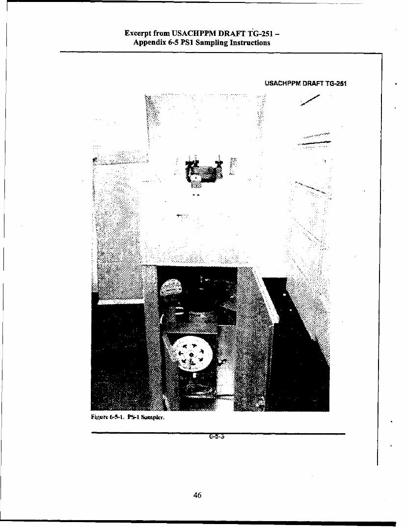
Excerpt from IJSACHPPM DRAFT TG-251 -
Appendix 6-5 Psi Sampling Instructions
USACHPPRE DRAFT TG-.251
4iur 6--.P4SeP/'
46
Excerpt from USACHPPM DRAFr TG-251 -
Appendix 6-5 Psi Sampling Instructions
USACH4PPVM DRAFT TG-251
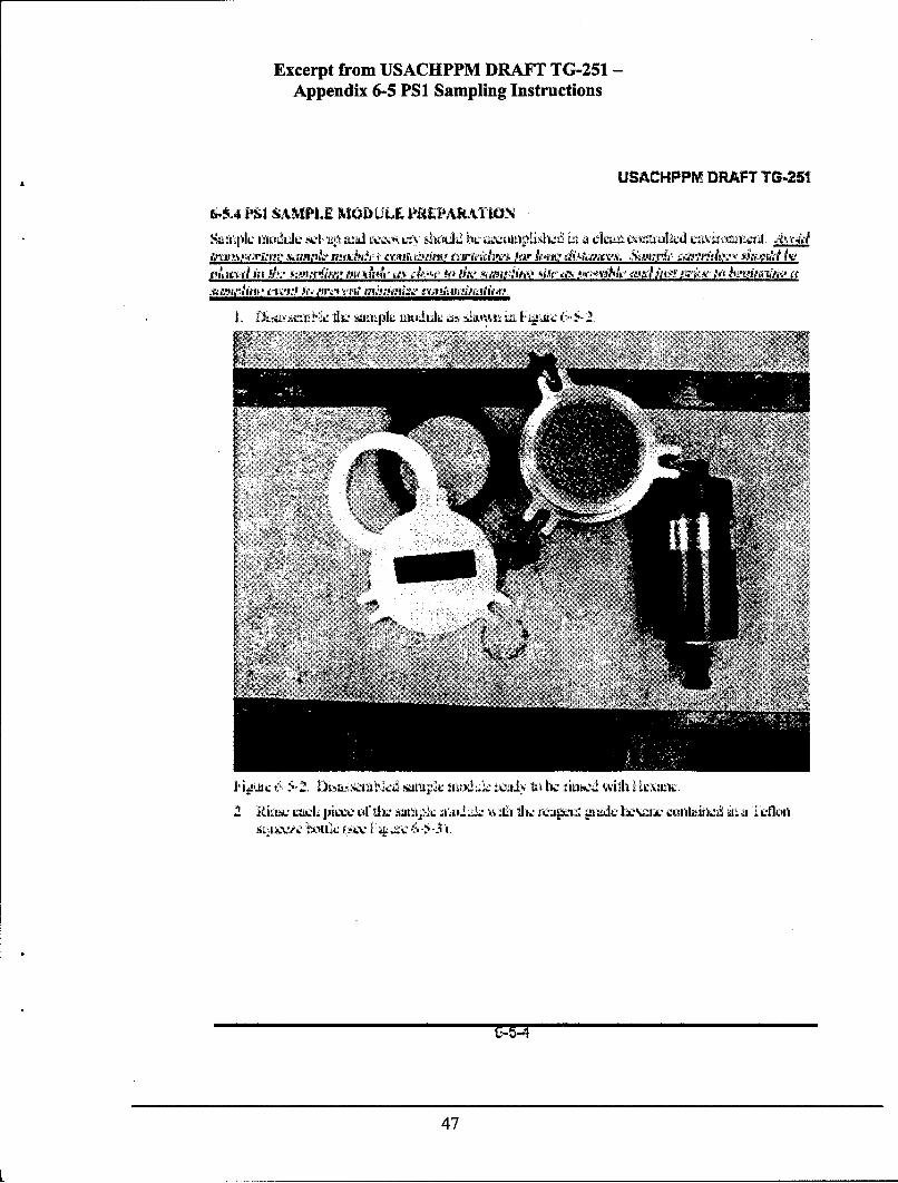
6--k4 M~ SAMPLE MOLD LLE PREPMUA10aN
iI 3 i WIL SM-CI IAL I 1 LJL I .AL i~.I Z
N.LL j1~~.u~ .~ji vtz2 l~ I.~kiin 4t f~1. C~Lf
47
Excerpt from USACHPPM DRAFT' TG-251 -
Appendix 6-5 PSi Sampling Instructions
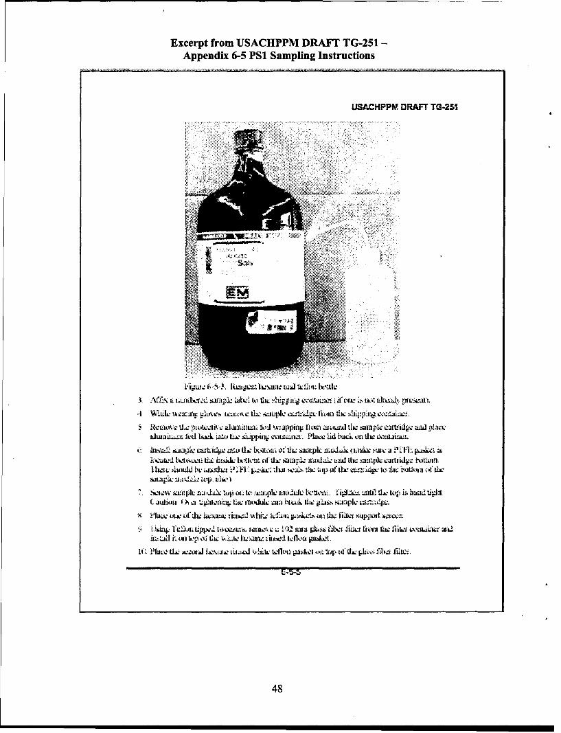
USACKPPM, DRAFT TG-251
3ALL .a ll'" aikx:. kai t kit lil' .L u ;idf ti ' att ltIi
hklwai~u kid lAwk Lt'f LUX kaui4)it cwztkAz. muice lid hu a othi oa12 L~tillea
it kbL s.aMc c-a Li de aId 1a Loitunt C d 211 h Safpl wIOL,i a akc ! t: j ?, FL, OkaL t~Vd%1 ~d~xIwt tLsi& b1tttvut ii 11 swnk m4al: taiwl sunq*2 NUU itipk L I1I winflf
I I21i ~.addk a±CU ~; E ~C.L JUit ,jI Ilic "up ofL rd u:ilw to ut'kiliiut of tile
C kiui~ (0a -.1 u lixL itimoduk- am btc& tic gali. bsjlc canz. 4.
it tit)~ [ olf 112 IAt;,'" Lbv ~Ivet e tcf a p4.u- ticIu Mpo
1C. 9PIAW LUt ±ccttd ItALLI tJ tefl01 PL1kaI t't lIS tat Ur& tjIzis, fiba2 fill"..
48

Excerpt from USACHPPM DRAFT TG-251 -
Appendix 6-5 PSI Sampling Instructions
USACRPPM! DRAFT TG-251
13. 1 i u t 111M pi t%% t'4 1 . i jnjut, kj bia tk-~r:a.! iiik: O I, ~ v.,
BAL; 111. 931-111 it vle kzaonoi oPI -u Ii lx A. i1Ig-
J!Wt~i ML hiJA Ylee- JL 1 * i') 1% lo'F
to-.k5 2 PS SAMPLING FILDSE-U
C, X~jL - CllIiaI hkv4itu. k ok Jz
49

Excerpt from USACHPPM DRAFT TG-251 -
Appendix 6-5 PSI Sampling Instructions
USACKPPMf DRAFT TG.251
ICUt 1 -- L ixiceP$. .Jpif P Jp:LL aim S Lici
. CdsAi i 1 ti ausflwc as Ux : itetume- talm ip
- T.L. 12' - ?daL..l U)w iittnh LIA kiibn. ~ntiljr Ojt ZLI t'S .h Lt..' a: dUJ jlja. SLJAz
PSI41 SAM)E SETU AND SAMPLE~in InLAd4J
I-aw 1t .u4'awLi I ifl;f 1LoveU f- PL'K~LU l I.: anh1',. f r ' Iiw C1JtL.'L aiQIL .aixs) Cti A
4.%i11 ,tlf tJL~ I AtI dxski L."!1W)etA'+XIN0..1PC K
L- !t.,AbknAl'Cl : iven - ti. thei, No icitki unetLc ; twe 21 fItn -x-1OLXLI a l i do t 11011 wttl. it nF.'L- a p L. pl1a1 LLIwItSJ. ividhkl Ifl..e
alm iawn xi c Oha ti5l. .tl sui ub t IUW-IL at a Ia :a. ipuie tei
- Itzlli&n !1 aA14" li ti n4.v gtli ., iwsc ka~. 11a:1, uidkv4 un,Jd saaaLJ\JSA ki-atn 1v f ' s :k. I w :. l oban.t Lit LcJrNAJ.A]'.Cl zi
Sk50

Excerpt from USACHPPM DRAKE TG-251 -
Appendix 6-5 Psi Sampling Instructions
USACKPPV DRAFT TG-251
Calr be Lnl'utwJ,"ihe tw tlic, l'4 lC iIvo.tv kn ia .r. t t,.4tt A Oe1
~% r~ L'1 LriLi ili cil4 not IN &!toLtkautaiYwn vutL~pIII ol "A Jaldpi' CVoxu,!
lU*a'fA divunl ;42.'rkiskun, tIwM M,is fsWJhE& U(tWif#Iu~ta 'q"Arr dlt
-tfhI ec "L' Aj~vix. AS. &ri I ta remiakkumc.Alic xcui t.saeh, $ itnouk--o '.aL tkv !ntc a imtPatkL4 L" , ___ f h
has Alc C JLJ± itww3tcZii4'e.t ieiiL1,t"nizll ~lj .. :LIf. qxaw. te
SK-a Ictd '" t 124 4idekAIL tc.1k~; 0. (IN:L 'I taJJ ZmL F icsu DaZ4 SCLit
IC .I ML ia %.. U I tc t::[-Id d ir at' 1 -=! thl 1Ofii pIaCtlf ( itI I~ g)!a-nd C a Citbi" .Lt:1 , izt. Jr" -e
I1 I kt";uz: V. fir Siapikij sue a Iaia . ti LOdai tbc ilN~4 O-ilt 111d tcaad leL IzWiC wislkz. isi I I I Cd. 9 1 SI)C AdjuA t fkiw I&eImolci hq. iftpnssitnz. IC42 thk
12 Ar lt, S minteW, VIApithe eal 012CI i swi.i;Ii n m: t zcit K'i tvie1 sjnltpI2 SOV ski. to natidtOw fil znananLak xai LllF.
6-5.7 PSI SAMPLE WILMA RECOVLRY
t~A., i rdM~i Lt crp ILt.O Ntkil acauld ntnrn Lo fhlkut~on ,;It i. Li 10 IU4C tU
klnedtie clapd 1X4 111C lit" la sa Izt) ill
Iinthu. wL %van "s the tcadivo, is, #iic~ A 2 tLait~ 64 il Lie icitap~ng hiL k'4'; a,
2 Into ffLL PS.Ifl~
3int CL ove pk.w oln ahi: s iaut w'ule: !wtd -tt ai imtcn te 3; fu~gei nuli.
'i~ iiL1ch the: )nILZ adist:d". ti tu.tvmltt J111 wrElwc fi(la the sanuapler.
5, i Jsu~a zL luanm>' fi4' beaL CuiflA (1wcP vlpk nx c L11c2 czL:
'> USu Mid weetthi I"" zmbma t 1atiZ 1Pj C.
(Y~tu. ad :cntdLu.. Zwlt'ioi la-tUII1tkiL. jitsut. KfA&", ia ill 1Ig
51

Excerpt from USACHPPM DRAFT TG-251 -
Appendix 6-5 PSi Sampling Instructions
USACIIPPM DRAFT TG-251
62A~ SAM.PLE MODUt.LE [LLCOV £RYPROCEOUI&I
I *jLi kin lid 4tia -isL -lnu fo~i . a~ dl eu .: n~l w u~.. i~
O'k lb LI:ILVVii JW OIIL LIL I I Ll it91U ftkiL k II 1'~. it it till
1k 1wLJI Ov tIAa ta an sm (tL. t JiA Li i.k it', eU fi catini~ aiu t i. i
th. cauit 4L' pe tc.tAa th.: 12L Lad i~ aid~tiia pwkiap. pz.el1 ub. la. ~=r
I I Ur~jw!et the jfl!a,.ij LIV m~v tln. a,fileju
6 -5. PACING~C AN~D Sft1PINIG VNST1RUCIIONS
z. J" )1 m 4:nl as n'Ickn a N jx),ii -av hasl pl.: Jwmi1LW kti.: %hLud wk~t aw. 14L
LV,,".1 add iit aa.4 i
52

Excerpt from USACHPPM DRAFT TG-251 -
Appendix 6-5 PSI Sampling Instructions
USACHPPM DRAFT TG.251
Ait - PS I hield Data Sheet
-~~~~' Ad,,7 Nrh~Pt2
F &~~~ )pr~w 'tit
Sectrim II Field Data
I IL! 1 I'A
N. k."n P _____MW______._$_____1__(. .. 1 CW jryi
S5 -hre Cp - Shw
wa v
53

Excerpt from IJSACHPPM DRAFT TG-251 -
Appendix 6-5 Psi Sampling Instructions
USACIIPPM- DRAFT TG-fl1
rit ti U
Uteor lot I rg q, I ft . '~i o' *54 1 'i ' 10 .
,I '-'..wi. 5
j;!''r 3 " A ~ a- vm4w 44.4 rig. - I4IL t :, s,! 2fl
L4 Ir- ve4 '2 Li...r e is
I . '4.. It" -1.I .. ''. isis' t4,.4 , wp4 %k4 .4X1 4 v,'sr,. S I t L *.4. t,, .r1 XS.itI 4 Uh~zt r 4
2 %In4"' tU Mt V;4 "-: -1!'! nr tos -:k t4 kvJ L a
I s 1 ' % .-LA : L -. 44',Mn-.4* ,4 I
t4~ ~ ic a4442*£rs~I n ~ 4 tp4
17 Dolst I- 4e "itX dt~nt, . rtr;. . i tA I ,IIii P e
T4 it It . 'e "N-1 L 'I' 5.r ! 31.= .4tv, zvj ,7P(4 * hear -Aj4n 79 It.4 .. t. C.et %I ft - ,' , fl - - o
*.' ~ ~ f Ni. aris trfa s4i fir." atgnI' I,4 L ri
~ Tint t.'%'Avjv -,.?4I.4 Ur 2X 4;e..c ± r I",r'14441f
*It M61! I -SM W~. .. I%14.44. It,"I.4 U", . .1274 L ' r.11 --fI' 4
1454

Excerpt from LJSACHPPM DRAFT TG-251 -
Appendix 6-5 PSI Sampling Instructions
USACI4PPM, DRAFT TG.251
Appendix 6-5 - Annex 1
PSI Sampler Calibration
Hrj, it'tisthlb.s L l ' Aib-'t w;. Ut~c ask11 islt eP plCQLxlJC k CIJL S ti~ ilcahilUfin'n: 0.1 61L PSI siinni A a:NdUtL. A .aflpl vjxiia cai~naica rcLtiaztsltsk QL tocvdatinA4 ticid .'.'jPikj
11w tuLtLL25 LUilCJl tbL, A AIC N,=& WIL PS 1 ",:iecz dc A2iVtC. WJ.~,at IJ
-W4CZ: PS- Ilt I- ~i. i fiel
-, A~itI~w Ilja~0 ttlc.L f fir. 1PS I ;e j ttt Inuc. duw to wp.ILILVtzdk,- Caal i0i1 l5(plJ hows %vi.llw'L1
- L Itz . t2 L~L Li4n 1e3 zt Cx ,f thl. tr cJ ib tL..M fS "kly . Y1 owe th1a a %
-Wlaxn dijllIL:A i asljLe e ll zfedL WIWI otilrt. fiutt wibxh Ovr"naf..tez ua" ttirkx.J]kCJ kiLLwd tiq. w.11 txe uf. .l %~ilavu
N. till.z: pr4 spccitkxi0 in' tkx azl Swn Li'3ta ~ i~ii1 04W01" nl±aaI= an li:
11W icR~ ~a~~rL' pstd 10I vU.2 glIa-, ezcx s pIaCk L wAL i' paalwka XAJZria) C11 a p41t11Ux LrI*P ) plup. fkLw t" tL: dzffe.-Zan tnof. cia'acashta& of tlv vs
aj -wL ja~~i difhal'AI~as :are e njCak'L (ktcaiu -. d~z inn~ of Caiihlidionpoin &letI u. th ~nuW ad ad C a 11CI till JIhj Orlplt )t1ph;i ecck.. U1 to pcaw ia.
6-5.1.3ol cqdmn S., Inoi
Ihr ~Ait:f SL in ll' - .. c Iaud.ucdi: Wh claioln Ofr til I haaiapla.
55

Excerpt from USACHPPM DRAFT TG-251 -
Appendix 6-5 PSi Sampling Instructions
USACKPIPMDRAFT TG.251
fI c P o fis4 y1L IUL. i;L.n" Cit Iz Jac.*,Sn~Iz _________
SIUM %;4id' MAUL N~T
I -al"%Ad u,:~o1h c
aH. l U,%4Ain U IM%"h
~A)~ .~~a arguiia, ali'1fa I Jpaaqt'iL , Sw p u fI wluvolLn! t
Li, hjlIxeII 1.' 14, A 12N&JI H2 .. lao'u C futilL .. b WU P IL 120v1 f'urt
'.1 r k okev so~ Ux tiit F k w I 'j.sz' 'u- hzi sz pcr a- :z ua i~o zt- ,ill d., I fLv
U- OA 1ALW10C F01 WIS li~a~hu~. aa ~L ' . . 20,1S. 1.:k jnL
2 lh .. jtJ11 folow iIi*UIUAi0flI t- :LI IM CJA IL ;,ASILO11
S1.1 pai &JU
-G-5-1-2
56
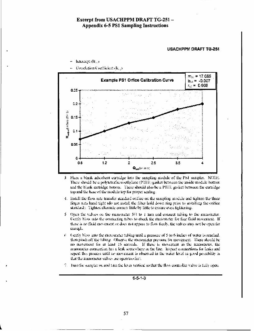
Excerpt from USACHPPM DRAFT TG-251 -
Appendix 6-5 PSi Sampling Instructions
USACKPPM DRAFT TG.251
Example PSI Orfice Calibration Curve =00-
OMcE
Tha'% -41Idh .I- 0,'f-EJk I I i:ar aC1.)LJ ho nl
a.J thL Kink L-witidge 1tkn't 1L till~~utd ab~ a i LPI. L''sc Lx%4 b tiw ew
..iIl ta [L)'. w~w lausf&l .ILaJ_'i et.S Cat cii. : si'ii= ai nik Lij!l*ti l d.' tui.
finp-1i 114 tig'Li. I'&I' t.! liik iiflk hod ll t il L aL'I U"AiWI~g tzj:: Wifi~e
*I-w vhiahx l th uILI. ;"ta 3.4 ; u ad vlug4. wri t lh 1 11:Uwa j:WL.
GC.= 1u .4)' tw d ~ tu. acikAk IL: i 'L f iw W. ud ti-kk wt, If4 Z~ICI lt !71d awI~l L~ o. dkw)t.ch. Ulti ~~'I ILI flOV vah-e. If~wk 11"i~ I±Ii9 E VY'-p44 ft~
"linull:i clk 2.L 4 LJhtk Wa t= UL A it !ILtlll IV lk andLbIWV UZ44Ih'i~ i IT I.,.' InOC11~ L J . libf iJ 1L fii I lLxjt'= la. 1; AI-A t.tLf
57

Excerpt from IJSACHPPM DRAFT TG-251 -
Appendix 6-5 Psi Sampling Instructions
USACKPPM DRAFT TG-251
uv I'h~ Jilt "Jli IJAL =11 Cfd.. I-JJd J f. UIPC' CA iL'L 1,4. COIiZ1- IZk. tIA:
Can: Plug We. holes no miore than 10 scorwis to prevent etankae to Ow. motor.
H WLl JL O ~ff
.IL 'n-lw Le ~ aIS It~ :mi.fc t: i L Lt l&~i 1J"t.W 4 x U th ifie I e-.L I L1 J
W~~~~w5 -,1V "111 Us lt -m~ ~Cb:1iL-i --- 1

Excerpt from USACHPPM DRAYI TG-251 -
Appendix 6-5 PSi Sampling Instructions
USACKPPV DRAFT TG-251
th.p L - i q rlk Ll ~ It uI.I.. La i ik~x . U13gidL~IL ' IiJ:.:
Nkf1L- Itill lifi lhh I *W i t widu ,t laed in 10 L1,! "l dillu~ Ih 11V %')) 14tI e a
p arta 1* &rv k e t hk otuL1 11 . jx ,1 t.ii ai M, 111L %j .. bi..auJ ILAC S~f1. ji ll3) f l, 3
I , kL tiz caiati.2k p~L*at: t~x I. i~~Li.k ~u~i i I
*PS I catafrut, ',hevt* Cu1Lt~i IJL ui. ., W.di.- Ul"!ii. to fl.& neaeslt UAAc
& ~~i :. flLag'iol.1l & P~ I
59
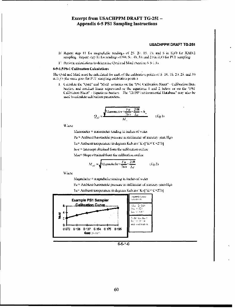
Excerpt from USACHPPM DRAYr TG-251 -
Appendix 6-5 PSi Sampling Instructions
USACHPPMj DRAFT T0,251
I(:,~ ~ ~ ~ ~ ~~~" R". ,lrail"o 5 ( I .WSi.""0kXj)-.Qapiitj . t~I~kii ii .~6i 4. !.3A a JL~i i A
ThLtLad NtAL.d w foi d t~aa Qs. Za tuis.. Ao=1 of *S" .IS,'1' AM
I L a.1.uLiucia C \IL . ta.d Lvwl." it. th I C'Uh Aiv ik ~ i , !,~~ t *Jili- ul Lkti';Svt%, uaJ W ULL~.a iqpc.';tji thi: c k4la.1L I ;Od Iti V Io 01k- IA VS
A'Ittiv.iiA kJilow L~iv plts~wv LI:. uilizxtv or m q iilgm:.1
1;. Azd'sznt kti .ijtu.-- ia Kukd i in I
M,= :icivtj vliwUd iu tl. *e- i alkwLufl codw
"a ALm.Not ka o ic,.i li LILI IiA jt 1tfli o it:vi.u'. ~L~if I
le CajtU I:xin kneti ik~l dn i"Kt kC+'5
Example PSI Sampler
06

Excerpt from LJSACHPPM DRAFT TG-251 -
Appendix 6-5 PSi Sampling Instructions
USACI-IPPMf DRAFT TG-251
2 ~~4 Lt: dii bILI ta AJ"" i afo. u.e 4 C:Lm v! -.. ,L akkgto LuL-Ululc :1k: S p.
k 4 1.A L~.-cpte cdA CAALA C iMI i h. utidtt tktj tccu~ia~ hat
JcIua.tce:1- .;1 ir h 'pL1.t% pIt 2ILa bL Lz-LXI WL pa.:~fC-'J LhL CIL~ tI'u
JLLt:uL' thc Luarw 1 lt
ad I' L C 1 I L ttJ1 I
liz' iJL4!&1JIL tiC32bJt, JA'1
X 3 jLC'fLgc &j"j hL ('d %jtc,
~4 IitA.. 1~ '
WIWILA~ . fu: cacl iijiCjt.O% e1iNAtnpvA
of' 1. i k taib'. aimn rlkt.15. 6.
3Caa-uhAc di.: %7td',ti andi Lti ovIkn %. ihL '?SI Cji~a:ua. M,4iiAt -. CuJJra1,%
us;d ikw ca.i iccJbi~'l
61
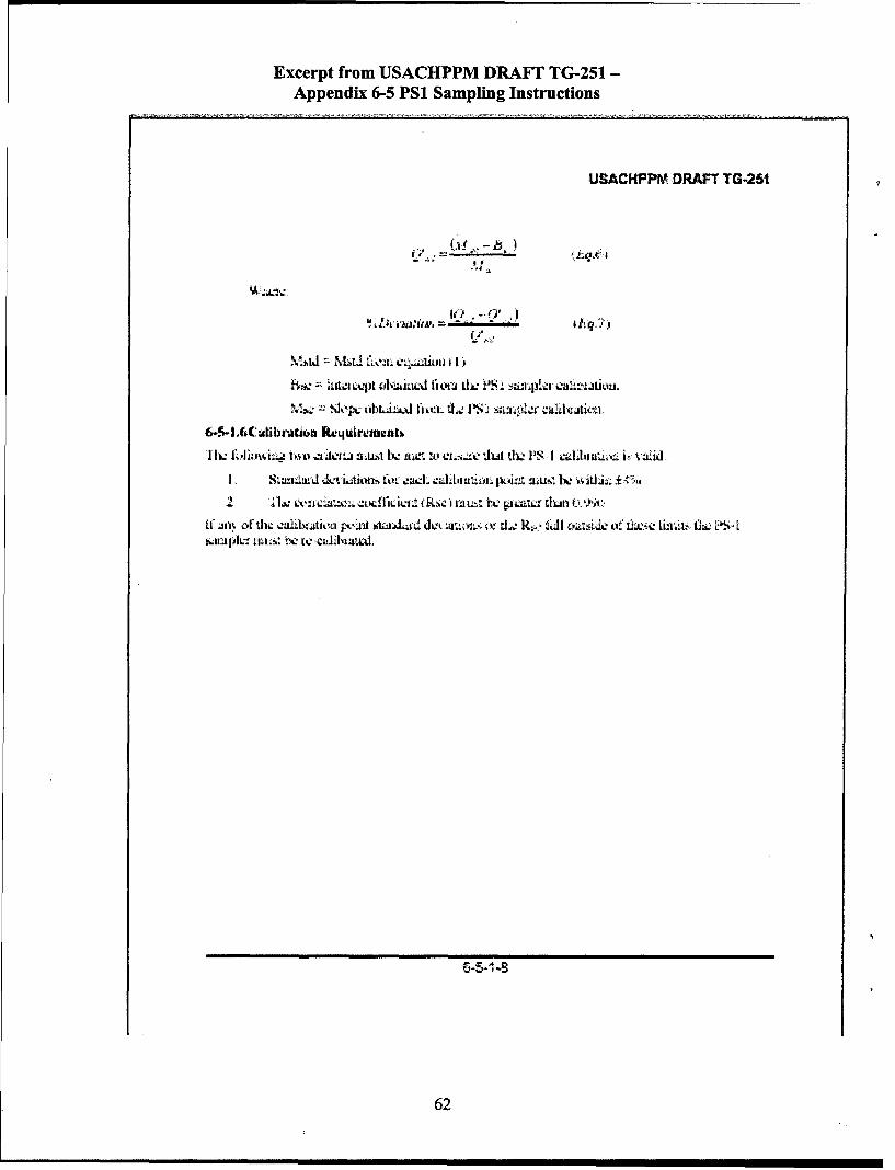
Excerpt from USACHPPM DRAFT TG-251 -
Appendix 6-5 PSi Sampling Instructions
USACHPPM DRAFT TG-251
01
T111WW Vt ~.JW f O. II P
62

Excerpt from USACHPPM DRAF17 TG-251 -
Appendix 6-5 PSI Sampling Instructions
USAC14PPri DRAFT TG-25t
Air - [PSI Calibratioi Field Data SheelSeti I -Adr. n? .stratvL Ayr
______ ert ion n, - arnpler LCibratfaft(_ !Lrnrn 4%lo
~ ~Aw~n~ A-UiLb I W .t
LQU r q iosLirRgeso okhe
I _ _ I _
77v4 f 7
2. ___ ___ ___ __y
* - -4_- -
kquaionst~nar RgresionWorkhee
ir.77111epo"x
* 63

Excerpt from USACHPPM DRAFr TG-251 -
Appendix 6-5 PSi Sampling Instructions
USACHPPM DRAFT TO-251
P'!SA KER'LR 41L~ATION MNSTRJ ITTIO2NN
S a r .nf i- ITP rf s3V r,, v35rwKr t', ~oai, v o gu&
4,Mir - am* wa m sivIr.4aZMrg lail J~t k:Afw ~~t t ;
cob, ~ A)4a1 rlfm %?,-,a Av )4LNJ1 4k% Wi4
Ito* OR SWI ~~~ n
toi lk ICAA*464 Swiun ' nTtle, vemlaij LUMNIV3~ ~JI~MwtrIa~~- ~e~n au ~ ~ dR461J~~~*.j~
1MaV4iM~4 B1~I1z~~ 1 ~ ~ ~ I
Pi -Z PaA 299
Is 4M. tANSWUMV-1:~ t
am760 fxV" F Ml27 frAwl#m C*"&
'IA fle keif I 4f*f) - tII"P0 C*,twxk t2betr tti6 bbmhs t~~lx c u kqrI,
&-5-1-10
64

Appendix DOil Well Fire Equipment List
65

Oil Well Fire Equipment List.ontainr Item Unit Quantity
I Blue Box PSI Sampler Body ea 11 Blue Box PS1 Extra motor ea 11 Blue Box Power Strip ea 11 Blue Box Isopropyl alcohol bottle 11 Blue Box PS1 Calibrator ea 12 Blue Box PS1 Sampler Hood ea 22 Blue Box Sampler Heads ea 22 Blue Box Sampler Feet ea 42 Blue Box Nalgene Bottles ea 22 Blue Box PSI Operation Instructions ea 12 Blue Box 550 Cord ea 12 Blue Box Aluminum Foil roll 12 Blue Box Screwdriver Set ea 1
Cardboard TSP Body3 Box TSPBody_ ea 1
Cardboard TSP Head3 Box ea 1
Cardboard TSP Motor3 Box ea
Cardboard TSP Filter Holder3 Box ea 2
Cardboard TSP Calibrator4 Box ea I
Cardboard Tripod Legs5 Box ea 36 Pelican Case SKC Pocket Pump ea 36 Pelican Case SKC Universal Chargers ea 36 Pelican Case Dry Cal Calibrator ea 16 Pelican Case TO1 7 Calibration Tube ea 16 Pelican Case SKC Pocket Pump Instructions ea 36 Pelican Case Sampling tube holder and tubing ea 37 Pelican Case Mini Vol Unit ea 17 Pelican Case Mini-Vol Sampling Heads ea 27 Pelican Case Mini-Vol Batteries ea 27 Pelican Case Mounting bracket and cradle ea 17 Pelican Case Mini-Cal Calibrator ea 18 Pelican Case Mini Vol Unit ea 18 Pelican Case Mini-Vol Sampling Heads ea 28 Pelican Case Mini-Vol Batteries ea 28 Pelican Case Mounting bracket and cradle ea 1
Cardboard Environmental Sampling Backpack ea9 Box I________ea___________1___
? _ Sampling Media - PM10 (Mini-Vol Sampler) ea 20? Sampling Media -TSP ea 20? Sampling Media - TO13 (PS1 Sampler) ea 5? Sampling Media -TO17 (SKC Pumps) ea 21
I ? 1 Sampling Media - OVM ea 20
66

CardboardBox Deployment Potable Water Sampling Kit / with cooler ea 2CardboardBox Deployment Soil Sampling Kit (3 containers) / with cooler ea 1CardboardBox Field Notebooks ea 2CardboardBox Sampling instructions and datasheet binder ea 1CardboardBox Pens ea 2CardboardBox Packing Tape ea 3CardboardBox 1600 Watt Transformer ea 1
67
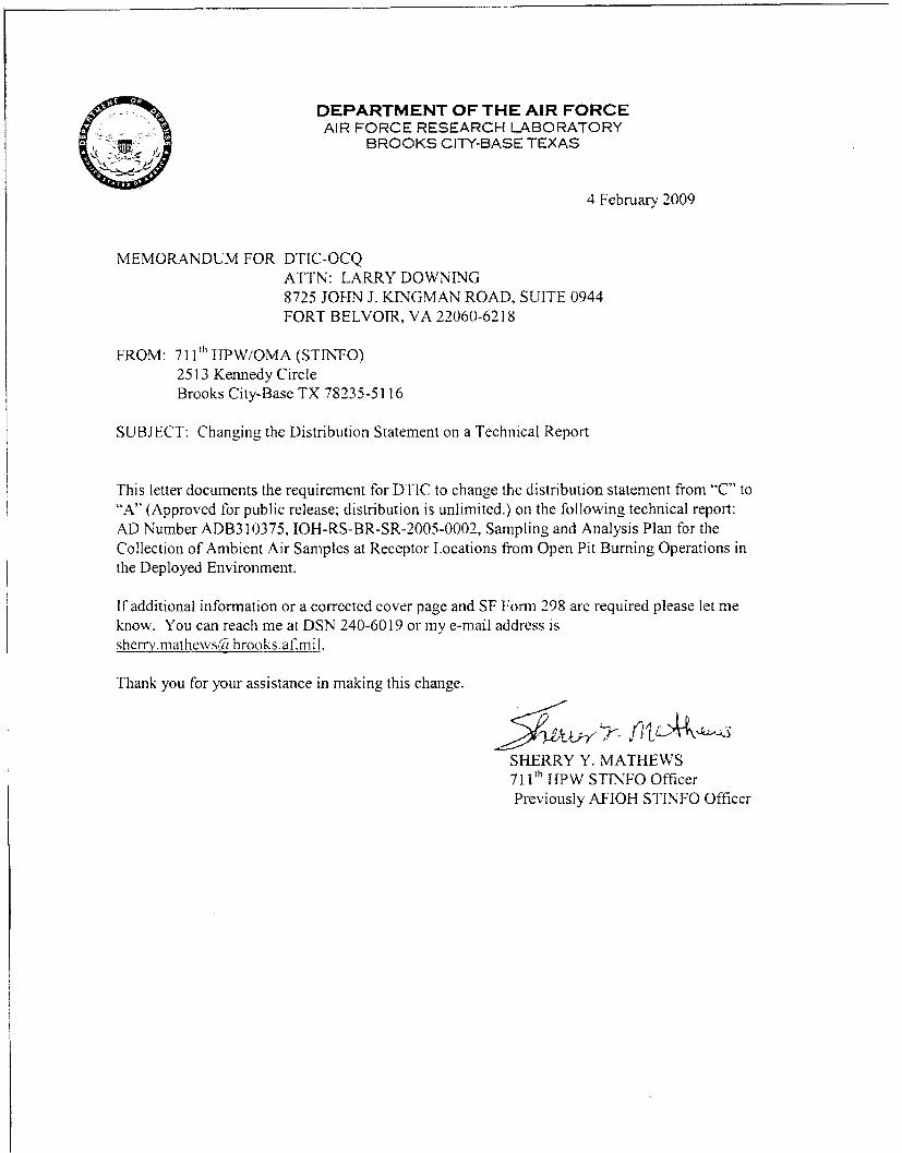
DEPARTMENT OF THE AIR FORCEAIR FORCE RESEARCH LABORATORY
BROOKS CITY-BASE TEXAS
4 February 2009
MEMORANDUM FOR DTIC-OCQATTN: LARRY DOWNING8725 JOHN J. KINGMAN ROAD, SUITE 0944FORT BELVOIR, VA 22060-6218
FROM: 7 1 1 ' TIPW/OMA (STINFO)2513 Kennedy CircleBrooks City-Base TX 78235-5116
SUBJECT: Changing the Distribution Statement on a Technical Report
This letter documents the requirement for DTIC to change the distribution statement from "C" to"A" (Approved for public release; distribution is unlimited.) on the following technical report:AD Number ADB310375, IOH-RS-BR-SR-2005-0002, Sampling and Analysis Plan for theCollection of Ambient Air Samples at Receptor Locations from Open Pit Burning Operations inthe Deployed Environment.
If additional information or a corrected cover page and SF Form 298 are required please let meknow. You can reach me at DSN 240-6019 or my e-mail address isshcrrv.rnathewsC bhrooks.afmil.
Thank you for your assistance in making this change.
SHERRY Y. MATHEWS711 "HPW STTNFO OfficerPreviously AFIOH STINFO Officer