Embed Size (px)
Citation preview

UNCLASSIFIED
AD NUMBER
CLASSIFICATION CHANGESTO:FROM:
LIMITATION CHANGESTO:
FROM:
AUTHORITY
THIS PAGE IS UNCLASSIFIED
ADC800782
UNCLASSIFIED
CONFIDENTIAL
Approved for public release; distribution isunlimited. Document partially illegible.
Distribution authorized to DoD only;Administrative/Operational Use; 1945. Otherrequests shall be referred to Office ofScientific Research and Development,Washington, DC 20301. Pre-dates formal DoDdistribution statements. Treat as DoD only.Document partially illegible.
OSD/WHS memo dtd 7 Mar 2013; OSD/WHS memo dtd 7Mar 2013


... iiuy'
OONFIDBNTIAL
Washington Project
Division 5, National Defense Research committee of the
Offiae of soientlfio Research and Development
Aspeots of the Design of Homing Aero-Missile«
m
Hugh X.. Dryden National Bureaq of standard«
A report to Division 8 from the
National Bureau of standard«
/
i :«*;••
This document contain« information affacting ttta national defense of the United states within tlM meaning of the Bspionage Aot, U.S.C., SO; 30 and 58. it« transmission or the revelation of its contents in any manner to an unauthorised i« prohibited by law. ,
/
Copy HO.
OOHf IDIITUL

OOiriOINTIAL
Aspeots of the Design of Honing Aero-ltlaslles
by
Hugh X.. Bryden Rational Bureau of Standards
A report from the Rational Bureau of standards to
DlTlslon 6, Rational Defense Research coanlttee of the
OfflAe of solentlflo Research and Development
A i
Approved for Rational Bureau of standard« by
Lyaan J. Briggs» Director.
OOHFIDBHTIAL
"mm

OONIISINTIiL
prefaoe
. I
The work described in this report ia pertinent to the
projeots designated by the Dar Department Liaison offloer ••
AC-1, AC-36, and AC-42 and to the projeots designated by the
Navy Department Liaison offioer as ND-115, NO-17«, and NO-S35.
This work was carried out and reported by National Bureau of
Standards under a transfer of funds from OSRD with the oo-
operatlon of the Washington.Radar Oroup of the Massachusetts
Institute of Technology and Section Reeg of the Bureau of
Ordnance, Navy Department.
f
•;.--v .••••»•M*>
il OOHIIDISTIAL

I
CONFIDENTIAL
Table of Contenta
Page I. Introduction x
A. Classification of Missiles 8 B. Necessity of Technical Coordination 4 C. Purpose and Background of this deport 6
II* Target Discrimination and Tracking 6
A. Limitations of Mechanisms aa Compared to Human Brain 6
B. principles of Target Discrimination 7 C. Relation between Field of View and permissible
Motion of Vehiole 18 D. Background signal 16 £. Fluctuation of signal intensity 17
TIT- Maneuverability of Vehicle and other Aerodynamic problems 18
A. The Six Degrees of Freedom 18 B. Equilibrium and Trim 88 C. Magnitude of Lateral Faroes, Angular Rates, and
Radii of Curvature 86 D. Non-lifting Missiles 89 3. Lifting Missiles 91 F. Powered Missiles 37 O. Homing Missiles . 38 H. Stability Problems 40
IT, Coupling Between Controls 48
A. Interdependence of Controls 48 B. Correspondence Between Intelligence Coordinates
and Controls 43 C. Effect of Roll on Error signals 46 D. Effeot of Angle of Attaok or Yaw on Error
Signals 48 S. Methods of Reduoing Coupling Between Controls . 49
•. system Stability or Hunting problems 49
A. Illustration of Hunting 49 B. Faotors Leading to Instability 81 C. Anti-hunt Devices 84 D. Time to Come on Course 88 S. Effect of Wind Ousts 56 F. methods of Analysis 87
CONFIDENTIAL ill

m „It >'!..'M
CO!flIDEHTIA,L .
...,|£fi£ VI. . problems ArisiEg from wiad and Koving fargefes . . . @0 .. _._,-. -A. Pursuit CWTCS •>......?.... so
' " B. Computers I I- I 82
¥11. lore Siglit aerors ......... 65 '
'VIII. ?£8??f of Sensitivity,, Lag, and Minimum Range of Intellige&e© Oevlea on pursuit curve and Bor© Sights SHOTS • •»........,...., . . gg
IX. steengfeti problems of Homing Klasllea ......"; 74
X. laußöhiBg problems of Homing Missiles .,....'. 75 •
XI. Conclusion . . . . • .-.....,,.., 75
i¥ 6 0 UF I DID T I A L
• UttXCw; 'u/HSfAw. £ '5;.L3 i\li i w:.JJ„'.' •,'.-.• sw
. ,'•• '

^ar
;.4£ä>: z- -x- OOIfISJVTlil
:?,sa
f '•jfl»;-'
-:'0
Modern nrftrt Is primarily a warfare of alssilss - ballot*,
«tolls, roeksts, bombs, sad arsasdss. loo chief problems srs
to transport» projsot or propsl, sod dlroot thsss aissllss
accurately to strifes targets of ailltary iaportanee. Mis alls«
say bs trsneported to ths rlolnlty of « target by asn on foot,
by aoblls artillery,' by tanks, by aircraft, or by ships, They say ba dropped froa aircraft, projeoted froa fius on land, abiti»
or aircraft, soeslsrstsd for all or parts of their trajectories .
by rookot motors, or they any b« self-propelled. Most of th«
aissilss in ourrsnt ass ars not undsr the oontrol of the ussr
after launching. SOBS font of sighting device Is necessary to
sstablish tbs initial direction of travel in a aaanar to causa.,; .
tnsaissils to strlks the'target, dun eights, boa» elghta, aaj|
tbs aoaplioatad sau dirsotors sat ooapatsrs ars aars aid» to ...
deteralae where to point tbs ana or rslsass tas boab, aad *f$fX'
ralaass of ths alsslls no farther oontrol la poeeible. ,,..;r?l
for aany ysars ausk tJmnght aas boon given to the yoaeV ,,;
bllitlss of gaidlng aissilss aftsr their rslsass to oorrsot fa»
srrors la sighting and for evasive aotloa of moving targets. .. -
Ate dsTslopasnt of radio nonaunlnation otlasleted inventive «»^^^f
activity la this fisld and «van dart a« the first «or Id mm-^rr,'"
tbsrs wars experlasate on radio-directed air «raft. ttere arj#,j,>
,li>waaarat|s aataa» aaylt oat tans relating sot only to radiew
.•&'£
:*•£$
•-. *> v j .
-•^f'- -m

I -2- C0K7IDENTIAL
control but also to other aspects of guided missiles. Particu-
larly attraetlva baa been in« Idea of missiles which will seek
out a target automatically or "home*' on the target.
During the present war muob serious scientific effort has
bean devoted to a full exploration of the practicability of
guided missiles aa useful weapons. The German experiments
with HS 293 and FX and later with V-l and v-2 have stimulated
the Interest of our military.leaders and enlisted their support
in trs fullest exploitation of the possibilities of this type
of weapon.
Classification of Missiles.
We may recognize five possible classes of missile from
the standpoint of the source of control. The first. Illustrated
by the German V-l and 7-8, uses an autopilot to hold the missile
oh a prescribed course. The missile receives no Information
relating to the target, and must be launohed In the direotion
required to strike the target. This type Is really a kind of
long range artillery although the missile Itself oarriea.a part
of the computer.
The second type, illustrated by the Japanese suicide bombers,
carries a human pilot in the missile, who is expended with the
missile. This solution is known, involves no new teohnloal
problems, but is not attractive to a nation placing a high
value on human life.
C'OSriOIRIIlL

-3- C0NFID3NTIAL
1
#
The third type, illustrated by the German HS 893 and FZ
and the Division S NDHC Azon and Razon series, uses a remote
human pilot who may either see the missile and target Visually,
aided by flares on the missile snd by sighting devices, or be
guided by a repeat-baok of television or radar information fron
apparatus contained in the missile, or be guided by radar
looation of the missile in relation to map location of the
target or radar looation of the target.
The fourth type, of which there is no existing illustration»
uses some type of beam directed toward the target which the
missile automatically follows.
The fifth type is the target-seeking or homing type,
illustrated by Division S NDRC Pelican, Bat, and Felix. 3uoh
a missile must utilize some physioal property of the military
target which causes it to stand out from the background. The most oommonly suggested property is the emission or refleotion
of electromagnetic radiation. Separate techniques are available
for transforming three major divisions of the eleotromagnetlo
apeotrum into directional information. Of the three - visible
light, infra red, and radio - radio frequencies, for technical
reasons, hold the most promise of useful weapons. Radio tech-
niques as developed in radar are directly applicable. Visible
light and infra-red are useful for certain speoiflo types of
targets, other properties have been suggested, for «sample»
the emission or refleotion of sound. Investigations along
OONFIDBNTIAL
-4- 00RTIS1KTIAL
this Uns for aero-missiles have not given promising remits.
Necessity of Teohnloal Coordination.
This report is conoerned with variouB aapeots of the •
design of this last type, the honing aero-missile. The
impression is prevalent that soientifio advances in many field«
have progressed to the point «here the development of such a
missile is purely a matter of engineering design on the part
of the several specialist groups with the usual coordination
as to dimensional requirements, weights, and time of completion.
Experience has taught otherwise« optimistio time schedules
based on such an assumption can not be met. The development
of successful homing aero-missiles requires the solution of
certain researoh problems associated with the oomplete artiole
involving complex relationships between the performance
characteristics of the oomponent parts. There is required a
type of overall teohnloal coordination beyond that required
la the design of alreraft as ordinarily practiced.
The required teohnloal coordination is made diffioult by
the wide variety of specialists of different soientifio and
technical background and aooustomed to different vocabularies
and habits of thought whose work must be coordinated. For
example, in the oase of a propelled radar homing missile there
will be represented experts in aerodynamics, aircraft structures,
propulsion, servomeohaniams, eleotronioa, radar, computers,
explosives, and fuses, other types of missiles will require
0 0 N.F I D X H T I A.X
i»,**t.*^t>-» •p.,-71«'*»!!***'«"1^'-"^^-"
CONFIDENTIAL
experts in radio, optloa, infra-red radiation, beat. eto. No
one person can be expert in all of these diverse fields» but
the suacess of the project requires a projeot engineer «bo has
sufficient Knowledge of these fields to be able with the help
of advice front the specialists to assume teohnioal leadership
in the solution of research problems associated with the system
as a whole.
In the design of any homing missile, there soon emerge a
number of problems whioh out across the boundaries of the
specialist groups. The particular design whioh seems best to
one group of specialists creates difficult problems for other
groups, and the requirements put forth by the several groups
as optimum are often contradictory. For example, certain error«
are introduced unless the intelligence devioe "looks" along
the direotion of motion, i.e. is accurately bore-sighted. The
conventional airplane flies at an angle of attack whioh varies
with the position of the elevator. If the aerodynamics
specialist adopts a conventional aircraft design with elevator oontrol, the intelligence devioe must be ooupled to the elevator
oontrol in such a manner as to compensate for variations of
angle of attack for all conditions of flight. However, the
designer of the intelligence devioe might properly suggest that
the aerodynamioist design a vehlole whioh does not ohange its
attitude with application of the controls, it becomes a matter
of research to determine whioh solution gives greater accuracy
CONFIDENTIAL
-6- CONFIDENTIAL
sad hence haw responsibility is to be allocated between the two
specialists.
Purpose and Background of this Report.
These broad aspects of the design of homing aero-missiles
are treated in the present report. An attempt has been made to
make the discussion general in character and applicable to all
such missiles, whether propelled or not. It should be stated)
however, that the disouasion arises fron experience with the
radar homing missiles of the pelican and Bat series, and this
account undoubtedly reflects the solutions there adopted, as
well an the problems peculiar to radar homing.
II. Target Discrimination and Tracking
Limitations of Keohanlsms as compared to Human Brain.
In visual shooting or bombing, the target is Identified by
the pattern of optical radiation as perceived by the human eye
and interpreted by the human brain. In radar fire oontrol or
bombing, the target is identified by the pattern of short-wave
electromagnetic radiation exhibited on the screen of a cathode
ray tube as perceived by the human eye and interpreted by the
human brain. During the flight of a homing aero-missile these
radiation patterns must be made to operate control mechanisms
and the element of interpretation by a human brain is absent.
This introduces many problems and severe limitations. A
mechanism can perceive only a limited number of physioal charac-
teristics of the target pattern and oan exeroise no Judgment
CONFIDENTIAL

I ::H:;:K:..
--._ii» tut r*»:.*« _xf arsmxim. «aw« af xn* «i«g-
tfbnaV fir «aipv mmartjcu* irar * ogrs.f-.i Tim* xxx*r »*... < Tbu*
«4 >tr*wa.- x,i B-«ttt.*jti-B» ,t dirwo. «.tax erxli «ü*« s fSwa
TTjfU. fr-at «n. tjti.c*. *•»f* -- * oamj-tji T.JUU.1 y^tier-*, ITx
T«x*:^ yrt**i-. •-.*-.-» :* tarrtl.spi»x" arc- *•* ais»:iits nax nXUAm
«^7 *is%.~* x*rgsr: »ixuBtisx*. xx* mas? fartr*?!* t*rf»i
*;vt*Xi.*.tt t*ix* l&as of * *na_l x_iL:r7 .-? JX:;S ,-X * Ury» ^.
tt **«•*, er act gamer ally. * few Isolated Jiagoattaatti«*
la • rediatlca satt«» «mlea äs sexärv-.s-e xacrly aalfonu rr.iR
tale aaiat of view, aircraft «Is: presaxt favsrsMe target
•itbetJan«.
frrinclta.es of target wiscrisixatioa.
Excluding the ease of a siegle isolated discontinuity In
»..': radiation pattern, wticx seldom ooeurs. the first calr.
problem of any honing missile is to determine the method or
u.n>.:.'.".a to be used for target discrimination, when several
targets are present. la the simpler devices the missile homes
Ofl the biggest discontinuity within its field of view. In
many homing missiles, means are provided to permit the initial
selection of target by a human operator who often has available
Information supplemental to that given to the control olroultu
of the missile. Means may also be provided within the mianlle
to keep truck of the initially selected target and to reupond
only to algnala from that target. 3ven in the simpler missiles,
the operator attempts to release the missile either with a
CON FIDS KTIAL

-8- CONFIDENTIAL
single large discontinuity within the field or on such a path
that a single target cones within the field and depends on the
precision of the controls of the missile to keep the missile
tracking this target.
in order to obtain information about the location of the
target, a homing missile must be directions 11 y sensitive.
Usually the received intensity of radiation is greatest when
the axis of the radiation-receiver is pointed directly at the
target. Thus Fig. 1 shows a portion of the response curve of
the receiving antenna of the radar reoeiver used in the Pelloan
project. The relative power is plotted in terms of deoibelSt
a logarithmic unit, but the power ratios are also indicated.
The width at 1/2 power is 23* and the width at l/10th power Is
43s. In other words a target at bearing 21 1/2° from the
antenna axis gives one-tenth as muoh energy to the receiver as
a target on the axis giving the same intensity of radiation.
The radiation pattern shown oan not be used directly
beeeuse there is no discrimination between right and left or up
and down. The usual praotioe is to scan the field of view, to
oommutate or phase the received signal intensity with the
soanning, and oompare right with left and up with down or per-
form comparisons in some other coordinate system. The on-oourse
indication beaomes then an equality of two signals and a
directional sense is provided, in pelloan, conical scanning
Is used, the antenna axis describing a cone of 11° half-vertex
angle. A commutator provides the phasing. If there were a
CONFIDENTIAL

*mmmm. If^if^^^^^^i'^^i^w*''^ •v.'*? ^^vK^^r^f-y^fy^K'"
-9- OOHFIDBNTIAL
variety of targets of equal intensity, every one within a oona
of half-vertex angle of approximately 82s would give signals
of one-half maximum power or more. This represents one method
of stating a figure for the field of view of the receiver, all
targets being assumed to return signals of equal intensity.
In Pelican, the target is "illuminated" by a radar beam*
and the direotional oharaoteriatios of the transmitter antenna
provide additional direotional discrimination, whioh is not of
interest in this discussion, in Bat, the missile oarries the
transmitter and the same antenna is used for transmission and
reception. The field of view is accordingly smaller than
for Pelican.
In other types of intelligence devioes, muoh smaller fields
of view are used, the width at 1/8 power being 10° or less.
This is advantageous from the point of view of direotional dis-
crimination of targets. Limitation of the field of view is the
first general method of seouring target discrimination. However,
a narrow field of view introduces traoking problems as will be
discussed later.
The second method of seouring target discrimination la by
means of aignnl strength. This oan not be entirely separated
from the direotional properties of the intelligence system, and
permits little choice other than to home on the strongest signal.
It is usually neoessary to include some type of automatic gain
oontrol to obtain direotional information at signal levels which
0ONFIDKNTXAX.
«*M -. •^•WnJtJif'aiau.^tt. *u*<t.-.^Liäf*ferfr* A.t1 iWi*IVtffJJ«""" -^.**^rf*sii.'^-.,#; .iA*i».ir... ..•aSMaVAurt^
-10- COVriDSKTIAL
nay vary more than a billion fold aa the missile approaches the
target. The strongest signal within the field of view will
govern the sensitivity of the reoeiver through the notion of the
automatic gain control.
Target discrimination may also be secured through the
selective notion of the intelligence devioe in responding to
radiation within narrow wave length limits. This is best
utilized when an intense beam .of the desired radiation oan be
concentrated on the target and the missile made sensitive only
to wave lengths within the narrow limits of the transmitted
radiation.
In systems in which a pulsed illuminating beam is used,
as exemplified particularly in the pelioan and Bat radar homing
systems, another method of target discrimination may be used.
This is range seleotion and synchronization. By making the
intelligence system sensitive only for a short period at fc
predetermined time following the emission of an illuminating
pulse, the oontrol information oan be restricted to that reoeived
from targets lying within oertain range limits, say within a
zone of x250 feet of the actual target range. For a given rang«
corresponds to a definite time of transit of the pulse from
transmitter to target to reoeiver. Naturally such a range
seleoter requires en automatic method of traoking the target In
range as the range decreases. The operation of the range
seleoter also requires the synchronization of the reoeiver and
CONFIDENTIAL

-11- coirr ID1NTIAL
the transmitter. The synchronization Is effective in dia-
orlmlnating against refleoted radiation originating from otbar
transmittera operating on the sea« radio frequency but with
different pulse rates.
The use of range selection is found to be essential In
radar homing missiles launohed from aircraft beoause of the
so-oalled "altitude signal", i.e. energy returned from the
earth directly below the alroraft. If a reasonable cone of
•ision is to be maintained, the directional selectivity of tha
antenna is inadequate to discriminate against the large
reflecting area lying beneath the alroraft. A range aeleoter
and range tracking device makes possible the elimination of
this signal in the oase of glider missiles, sinoe the altitude
la always less than the range to the target. Presently avail-
able radar homing devices oan not be uaed under conditions
where the target may appear at the same range as the altitude
signal, for example in air to air missiles at ranges greater
than the altitude, in the oase of ground to air missiles
using receiver only, the geometry is more favorable than for
the glider, and the range of the target will not ooinoide with
that of the altitude signal. For a send-reoeive missile, tha
missile will at some time be at the same altitude as the range
to the target and hence may thereafter home on the altitude
signal.
It is possible tb davlaa more oomplex meohanlama to perform
CONTIDSNTIAI, 3
i

-18- CONFISRNTIAL
warm diffioult feats of discrimination, for example, to permit
the launohing of a radar homing missile at long range without
advance seleotion of a target and to have the range seleotlon
device search for, choose, and look on a target when the missile
has prooeeded a definite distance. The limit of performance
is set only by the permissible complexity of the mechanism.
The suggestion has often been made that lower animals be
used as Intelligence devices, since their brain, like that of
the human one, oan perform difficult tasks of discrimination.
This possibility is perhaps the only one of adequate complexity
to deal with the pattern discrimination required to select, for
example, a particular building within the complex optloal
radiation pattern presented by a city, proponents of this
method point out that near meehanioal reliability may be realized
in animals by establishing in them a conditioned reflex
associated with the object selected for attention.
Relation between ffleld of view and permissible Motion of Vehicle.
After a target has been seleoted by the operator before
release of the missile or by the mechanism of the missile Itself,
the target must be traoked, i.e. held within the field of view
of the missile during the remainder of its flight. The simplest
method of tracking is to have the intelligence control the
motion of the missile so that the target remains within the
field. If this method of tracking is seleoted, restrictions
are immediately plaoed on the permissible motions of the
CONFIDKMTIAL

-13- CONFIDSNTIAL
vehicle whloh must be considered by the aerodynamics specialist.
These restrictions depend not only on the aerodynanlos of the
vehicle and the field of view of the intelligence device but
also on target contrast, characteristics of tracking circuits,
and behavior of the servo mechanism in the absence of homing
signals.
When s missile is to be released blind, the aerodynamics
specialist can oompute trejeotories for various release con-
ditions and so provide estimates of the time at whiob a target
in a specific location relative to the point of release will
lie within a speoified field of view. The relation between
field of view, servo mechanism, and aerodynamical character-
istics must be such that tracking will be preserved. The
oontrola must be sufficiently effective to check any overshoot
or the servo mechanism must have a memory to bring the vehicle
and field of view of the intelligence device back on the target.
For some types of vehicle, the aerodynamio design can be made
such that the trajectory without any homing signal will include
the desired target within the field of view. The larger the
field of view, the easier the task.
Before release of the vehicle, the target must be brought
into its field of view, and tracking i-n range established.
During launching and thereafter the motion of the vehicle must
be such as to maintain the target within the field of view of
the intelligence device. Memory oirouits within the intelligence
CONFID^ NTIAL

«•14 «• C 0 K F I I E H I I A L
head T»ay *s.llow the signal to fade out for short time interval®
said resumes tracking in rang3 when the signal level is restored.
If during tho period of so signal return, the vehicle removes
the "target ft*cm the f ield of view, the intelligence device is
unable to secure further information of targot diroetioa. The
permissible motion will depend upon the intensity of tho signal
returned by-the target« If the target signal ia only a small
amount of the background signals the effective cone,, of vision
is reduced {in present radar homing equipment) to about-70 percent
of its maximum width. Thus a smaller change in attitude will
be required.to lose directional tracking than if the tergot
signal is much -larger than the background«, since the average
signal level sad its consistency in amplitude depends on target
size, target orientation, and on meteorological conditions, it
is difficult to give definite design rules. However, the
eraaller the field of view, the smaller the change in attitude
required to refiueo a low aignal to the baclcgrornid level, and
from these considerations a largo field of view ia desirable. .
The behavior of the servo mechanism in ths abseneo of
signal or more exactly just following fading of the signal has
a definite bearing on the relation between field of view and
permissible motions of the vehicle. If the servo mechanism
maintains the vehicle on the course it was flying, the field
of view could be small without risk of losing the target outside
of this field should tho signal fade for a few seconds. If
CONFIDENTIAL'

' H« > «I Iff «l« ipL V1 W« W»;i" V::'
-15- C0NFID3KTIAL
however the servo meohanism maintain» the rate of turn and
pitoh whioh exist at the time of signal fading, the target would
probably pass outside a snail field of view before the signal
returned. Either of these types of performance of a servo
meohanism is somewhat idealized and not accurately obtainable
In any actual meohanism. The maintenance of the same sours«
is of advantage when the vehiole is nearly on the desired course
and loss of signal is due to fading.
When the vehiole is initially oouing on- oourse. it may
overshoot by a sufficient amount to lose track. If this ooours,
a servo meohanism which maintains the oourse of the vehiole
at the time the signal is lost will thereafter give no
opportunity for again picking up the target signal. The amount
of overshoot permissible will be larger, the larger the field
of view and the greater the target contrast.
Some of the restrictions on the motion of the vehicle which
are imposed by a narrow field of view can be removed by the
use of an intelligence device fitted with automatic directional
tracking, in this system the output of the intelligence devioe
is used to drive servo motors to center the field of view on
the target Independent of the motion of the vehicle. The control
Of the vehiole itself is then derived from the relative, position
or rate of motion of the intelligence device with respeot to
the vehicle, or both. The minimum permissible field of view
is then limited only by the preolsion and speed of response of
CONFIDENTIAL
—*—-• -v 4m
,;*>•
-16- 0 0 B 7 I D I K I I A L
the servomechaniam. The extra degrees of freedom may give rise
to more difficulty with stability of the two servomeohanlams,
one driving the intelligence, the other the vehicle. There
has, as yet. been no field experienoe with a missile pontrol of
this type.
Background signal.
All electronic intelligence devioes have a certain internal
noise level which can not be less than that produced by thermal
agitation of electrons in the input circuit. The magnitude of
thia Internal noise sets a lower limit to the signal which oen
be detected. However in actual praotioe there is a much higher
background signal representing the signal return from areas
other than that of the target nil ich also lie within the field
of view. Thus in a radar homing device the background signal
Is the reflected radar energy from the land, rough sea, or
other obstructions that happen to be at the same range as the-
target. It may be very small or zero when the target is an
airplane and the background is cloudless sky. In an optical
homing device the background signal is the reflected or emitted
optical energy from land, sea, or sky.
The important attribute of this unwanted background energy
Is Its variability not only from place to place but at the
same plaoe, especially with weather, in the radar case against
ship targets, the "sea return" dependB vary greatly on the
height and shape of waves and on the orientation of the wave
CONFIDENTIAL

S&f1 !
-17- CONFID H N T I A L
M:
Sr-
troughs with respect to the receiver. The performance of a
radar homing missile against a specified target la affected very
much by the condition of the sea surface, the permissible range
at release being reduced as the sea becomes heavier* because
signal returned by the ship is lower and the amplitude of signal
fluctuation is greater. Small targets may be lost in the sea
return regardless of their range. Similarly, missiles using
other parts of the electromagnetic spectrum encounter background
signals which usually depend greatly on meteorological con-
ditions.
The ratio of target to background signal may show large
short-time variations during the flight of a single missile,
and if the target contrast is not sufficient may produce
difficulties in traoking at long range.
Fluctuation of Signal Intensity.
As a homing misails approaches its target, the signal
intensity and usually the background signals also Increase very
greatly, making necessary an automatic gain control In the
electronic equipment. The time constant of the gain control
must be short to take oare of the rapid change at the end of
the flight but not so short as to obscure the variations of
scanning frequenoy which give the direotional Information. The
reliability of the Information obtainable is dependent on the
target contrast which Is a function both of the background
signal and the strength of the target signal Itself. in
COKFID N T I A L
"*J***fcv-JAi^-«
-18- OONriDlNTIAL
addition to the slower variation of signal strength as the
missile approaches the target, there may also be nor« rapid
variations assooiated «1th the obanging geonetrioal relation-
ship between missile and target produoed by the motion of the
missile and the linear and angular motions of the target. Suoh
fluctuations are always found in radar reflections.
The presence of fluctuating signal intensity and fluctuating
background signal means that the missile and servo meehanism
oan not be designed on the assumption that information as to
the angular bearing of the target is continuously available.
The effects of fluctuating signal intensity whloh must ba
guarded against are possible resonance effects in the aervo-
meohaniam, synchronization with the frequency of soannlngt and
loss of tracking. It is not praotiosl to lay down methods of
design. However, in the radar oase the H.Z.T. field experiment
group working on pelloan and Bat have found It advantageous to
make photogmphio records of variations of signal strength of
aotual targets, to construct a special signal generator whloh
emits variable signals controlled by a oam out to the observed
variation, and to test the effeota of suoh a signal input on
the intelligence devloe output.
III. Maneuverability of Vehicle and other Aerodynamic problems.
The Six Degrees of Freedom.
The trajeotory of a missile is determined by the foroe of
gravity and the reactions between the missile and the air
CONFIDBNTIAL
-19- CONFIDBNTIAL
through «tiloh it files. The force of gravity aota vertically
downward through the oenter of gravity of the missile. It is
convenient to represent the resultant of the aerodynamics
reactions by three mutually perpendicular force components
acting through the oenter of gravity and three moments acting
about the three axes- along whioh the foroe components are taken.
These foroes and moments on a given missile are functions of
the shape of the missile, the orientation relative to the
direotion of motion of its oenter of gravity, the speed, the
axis and amount of angular rotation, and the density and other
physloal properties of the air.
The missile has six degrees of freedom, three linear and
three angular. The interest of the user of a missile lies
essentially in the three linear degrees of freedom, i.e. in
the linear motion of the oenter of gravity of the missile. The
angular motion of the missile is of interest only in so far
as it modifies the three foroe components and thus the trajectory.
A spinning or angular hunting motion is of no interest if the
missile strikes the target, a result dependent only on the
path of the oenter of gravity. It is generally true for the
ordinary bomb, propelled airoraft, or glider that an absenoe
of angular motion gives a more prediotable and constant
trajectory. But in some other missiles, for example, shells,
a spinning motion is deliberately provided to provide a more
stable and prediotable trajectory*
coirisnTiAi

-20- COKFIDBNTIAL
The dynamics of a missile, even If restricted to airplane-
like or bomb-like objects, is a very oomplex subject, and hardly
appropriate for this report. Readers are referred to Vol V of
W. F. Durand's Aerodynamio Theory for a discussion of airplane
dynamics by B. Melvlll Jones. Only elementary and general
aspects will be discussed here.
The path of the missile can be controlled in a number of
ways, but the most usual method is through changes in the aero-
dynamic reaction by means of changes in shape of the missile.
The other methods may be advantageous in speoial oases. Thus
by the use of rocket motors it is possible to apply reaction
forces on the missile to change its path. This method is oper-
ative in the stratosphere where the air density is very small
and in free space, control requires the ejection of a part of
the missile, a process differing only in degree from the burning
of fuel to produce power to operate other types of oontrol
devices. Where other types of oontrol are possible, it is
usually more economical to use them.
A missile may be controlled by varying its mass distribution
to modify the position of the center of gravity, thus changing
the resultant moments of the air reaction, honoe the orientation
of the missile, which in turn modifies the force components.
This was done in early airplanes by motion of the pilot but the
method has been little used since tuet time. It is possible to use power driven devices suah as pro-
CONFIDSNTIAL
-81- C0NFID3NTIAL
pellers or turbojets or to use thermal Jets to produoe forces
to modify the path or to use auoh devices to apply moments to
the missile to change its orientation and thus produce foroes
to modify the path. It is more common to use these devices
as propulsion elements, and some oontrol of the path, especially
changes in the vertical plane, is accomplished by varying the
propulsion force.
The most oonanon method of control is through changes In
shape of the missile which usually alter the moments of the
air reaction and change the orientetion of the missile in
addition to modifying the force components direotly. The use
of a power driven propeller may be regarded as a special case
of a periodio change in shape. All changes of shape for
purposes of oontrol involve the application of power, which
may be derived from any of the usual types of power sources.
It is obviously desirable that the power required for oontrol
be small. This has led to the conventional type of oontrol
used on aircraft in which the primary effect of the controls
is to apply moments to the missile which in a time determined
by the angular moments of inertia and the magnitude of the
applied moments changes the orientation of the missile to the
direction of motion of its oenter of gravity. As a result of
the change in orientation the forces are changed and the path
of the center of gravity is modified. We shall see later that
there are advantages in. the design of homing aeromissilea in
CONFIDENTIAL
££§

•."»ip.V30*a**» H«**,-
-22- CONFIDSNTIAL
selecting a ohange in shape which produces little or no change
in moment but does produce directly changes in the force com-
ponents, such a method requires greater power for operating
the controls than the conventional method.
equilibrium and Trim.
An unpropelled missile can be in complete equilibrium only
if the moments of the air reaction about three mutual per-
pendicular axes through its center of gravity are zero and if
the resultant air force is equal to the weight of the missile
and acts vertically upward. Such a state does not exolude the
possibility of a spiral or spinning motion. In fact the tail»
spin of an aircraft is a steady motion in «faich the above con-
ditions are fulfilled. We shall however not oonsider such
motions further, although there is no logioal necessity of ex-
cluding spinning missiles. The guiding of such missiles would
seem to introduce many teohnioal complications.
The equilibrium of a propelled missile differs only In
that the resultant aerodynamic foroe must equal the resultant
of the weight and the propelling force.
practically all missiles now used or under consideration
have one or two planes of symmetry and a longitudinal axis
which lies within 10° of the intended direction of motion. The
exaot location of the longitudinal axis is usually ohosen to
suit the convenience of the speoifio problems but always in
a plane of symmetry. The other mutually perpendicular referenoe
CONPIDBNTIAI.

-23- CONPIDBNTIAL
axes are oalled the lateral and normal cucea, and if the missile
has only one plane of symmetry, this plane oontains the longi-
tudinal and normal axes. In the practioal oonstruotion of air-
craft or missiles it is found impossible to make the de74.ce
sufficiently accurately to insure that, when flown or released,
the aerodynamic moments about the reference axes will be zero.
It is always necessary to apply control moments of suitable
magnitude about all three axes, or if it is desired to have the
controls in a given neutral position with no foroe applied to
the control levers, to provide adjustable trim tabs. These
adjustments are easily, made when a human pilot is on board, but
other provision must be made when unmanned missiles are to be used.
For unbalanced moments about the lateral and normal axes«
a stable missile compensates by angular rotation to new positions
of equilibrium, sinoe displacements about these axes produoe
restoring moments. The missile would then fly at a somewhat
different angle of attack than planned and at an angle of yaw
which would give rise to a lateral foroe producing a lateral
drift of the missile. An unbalanced moment about the longitudinal,
axis, which lies approximately in the dlreotion of motion, can
not be compensated in this way, because rolling about the
direction of motion produces no statio restoring moment. The
only methods known of compensating this unavoidable and undesired
moment arising from lack of symmetry in the actual unmanned missiles involve automatic trimming by control surface dis-
CONFIDBNTIAL
• *l MawYiHfl «frl'lT VimsV
M
-84- CONFIDBNTIAL
placements under the oontrol of one or more gyroscopes. The most
desirable method is to compensate the undesired moment direotly
by displacement of ailerons. In some oases, for example the
German robot bomb V-l, the autopilot moves the rudder thus forcing
the bomb to i-ravel at an angle of yaw sufficient to produoe a
rolling moment due to yaw equal to the unbalanced rolling moment«
This method of correction gives rise to a lateral drift which
Is one; source of error contributing to the dispersion, one of
the results of the early work on the pelican and Bat developments
was the demonstration that provision must be made in the auto-
pilot for compensating for undeslr'ed aerodynamic moments arising
from lack of symmetry, i.e. "trimming" the missile, and that a
gyro or equivalent reference is essential, it is fairly well
known that pendulums or aerodynamio surfaces whos-a position la
controlled by aerodynamio reactions are ineffective for this
purpose, in the Azon and Razon developments it has also been
found desirable to introduce automatic trim devices to eliminate
rolling motions, although not there required for stability
reasons, sinoe these missiles have two planes of symmetry. The
elimination of the rolling motion in those missiles simplifies
the control problem as will be discussed in the section on
ooupling between controls.
The state of complete equilibrium Is rarely attained in
the praotioal use of missiles. The linear motion of the center
of gravity is an aooelerated one, the mass times the aooeleration
CONFIDBNTIAL

w^= i». i.naupi mu
-85- CONFIDÄNTIAL
being equal to and la the direction of the resultant force.
It» tine required to «each equilibrium la often much greater than
the time of flight of the mlaalle. For example, a falling
bomb la In complete equilibrium only «hen it reaches its
terminal Telocity, a prooess requiring fall from a great height
and many tens of aeoonda. This long time constant arises fro«
the limited rate at which energy is supplied from the gravi-
tational field. In the oaae of an alroraft the alow pnugoid
oaoillatlon arising from interchange of klnetio energy and
potential energy has a period of approximately 0.S2V aeoonda
«hen V la the apeed in ft/seo, i.e. 86 aeoonda for a missile
traveling at 400 ft/seo. The design of servo meohanisma and
Intelligence devioea oan not he based on the assumption of
equilibrium conditions.
Fortunately the time eonatants of the angular motions are
muoh shorter, usually of the order of a fraotlon of a second
or at the most a few aeoonda, inoreaalng somewhat with the als* of mlaalle but decreasing with Its speed.
Magnitude of Lateral Faroes, Angular Rates, and Radll of curvature.
Consider a eyametrioal missile falling vertically with its
longitudinal azla alao vertical. The forces aoting are the
force of gravity and the air resistance. Because of symmetry
there are no lateral forces* The downward aooeleration will
be equal to the difference between the aooeleration of gravity
and the ratio of the air realatanoe to the mass of the missile.
! i
CONFIDENTIAL
x-^u iJrflaaaJMl'iMl^inftealtalJii-aalaaiili*

-26- CONFIDENTIAL
Tae aooeleration «111 ultimately approach 2«ro a a to« missile
approaches lta terminal valoolty at whioh the air realataoo«
equals the weight. At any point along lta length the tra-
jectory may be modified only by introducing a lateral foroe.
This foroe Imparts a lateral aooeleration whioh causes the
missile to travel in a path whioh is approximately oiroular for
same time. To move the missile in a path of radius R requires
a oantrlpetal aooeleration of VVR where V is the velooity of
the missile. The rate of ohange of direction of the trajeotory
H equals V/R.
The usual method of seourlng a lateral foroe is to ohange
the orientation of the missile so that its axia makes an angle
to the trajectory. The missile does not then travel In the
direction of its axis. The ohange in ita direction of motion
is dependent on the magnitude of the lateral foroe produced by .
the ohange in orientation in relation to the mass of the missile.
If the foroe is small or the mass is large, the trajeotory will
be modified very slowly, even though the axis of the missile is
at a large angle to the direotlon of motion of the oenter of
gravity. The missile behaves in the same manner as an automobil«
traveling on loe when the steering wheel is suddenly turned*
Experience from testa on bombs and airfoils shows that
the lateral foroe produced at a given angle of the missile to
its trajeotory is approximately proportional to the square of
the speed and to the projected lateral area. A reasonable value
OORMDHIIil
. i, nMimnn
>1Ti —Ul .|!W-I!|P,.IW
-87- II F I D B N T I A L
of the lateral fore« ia about 10 lb/ft8 on the fine or wings
at a speed of 100 ft/aeo and aoout l/S lb/ft8 on a body of
revolution at a epeed of 100 ft/aeo for angles of yaw o* 18»,
although with larger angles of yaw still higher values can
be obtained. Sxtremely large angles of yaw give large drag
foroea which alow up the missile and thus reduoe the lateral
foroe. The lateral aoeeleration to be expeoted ia therefore
about lOAi V ,8 'iOO' * wh*• A is the area of the fins or wings la
aquare feet, V the apeed in ft/aeo, W the weight of the niseile
in pounds» and g la the aoeeleration of gravity In ft/see8.
In any aetual design, the lateral aooeleration should be deter-
mined from wind tunnel measurements on a nodal of the nissile.
A radius of ourvature R requires an aoeeleration •*/*•
yg/R - O'gyAY*
or R - 31 |.
The rate of ohange of direction £| - w^jf •
For the standard 2000 lb bomb, A for the standard fins v
is sbout 4 square feet. By a suitable rudder, it nay be
expeoted that lateral foroea of the above magnitude may ba
reaohed, in whioh oaae R - IS, 500 feet and jS - Tghjrt
rad/seo. - 0.0037 v degrees/seo. in the next 500 feet of fall
after the rudder la applied, the bomb would move laterally about 7 l/S feet.
OOMFIDIHTIAL
*mmmm

OOHriPIITlAl
It la to be not*« that for this of • vartloal tra-
Jeotoryt the radius of ourvature obtainable with a given fla
too« not depend on th« epeed, alaoa both th» required and to*
available aooalsratloo vary aa tha aquare of th« apaad.
th« foroaa «hloh tha alaalle atroetara must wlthataad lnoraaaa
proportional to 7*/H.
When tha trajectory malcee an angle to tha vartloal, tha
foroa of gravity haa a aoBponaat at right angles to tha tra-
Jeetory. it la ouatomery to meaeure tha angl« from tha horlaontal
and to danota lta value by •. Th« gravity somponent la than
g oos •. fhe path than eurvea downward unlaaa a auffloiantly
larga lateral aerodynamle foroa overoomes tha gravitational
oompoaent. Calling tha lateral aerodynamle foroa L, «w have the
following aquation for tha radlua of ourvature of the path
vffe oT mg ooa • - L
Ooaaldar flret the aaaa In «hloh L la aero, I.e. e eon*
vaatloaal bomb, we find H
«eine of d6 IT
i ooa • and de «y • . Ilia oooura whan tha axis of the bomb la horlsontal
and equals f rad/eeo. At a speed of SCO ft/aee, 32 - 0.1 rad-i oT 5.7»/s«o, and H • »BOO feet. Aa the speed lnoreaaea. i§ deoreaaea
and B lnoreaaea.
Hext aaauma that tha trajectory of the mlaalle la to be
approximately a etralght line to the target aa la uaually desired
for s homing mlaalle. in this the-average value of h
OOIIIBlIfllt

-89- COKFIDSHTIAI
I equal ag torn •• lb* available oontrol then depends on the changes
In X» whioh ou be affected by the eontrols, and the ooatrol 1«
the aaae as for • vertioal trajectory. Howarar, the requireaeat
L • ag ooa w ia tha requirensat for raotilinear flight and th*
apead required la dependent again on the area of fin* or «Inga«
The ainiana «peed for rectilinear flight, aaaualng tha UM of
the asvlana oontrol, la given by
ife -VF ooa 9
for tha 800Q lb bomb on a 45« trajectory, 7 la about .600 ft/aeo.
At lower apaeda than the mlntimim apeed for reetlllnear
flight, the rate of ahanga of dlraotion la not aa great and the
radlua of turn la larger, values for any particular oaae oaa
be eatlaated. The oontrol obtainable dependa greatly on the
ratio of tha apeed to the reotillnear flying spaed, and the
reotilinear flying apeed ia determined aalnly by the area of fins
or wings.
Kon-llftlng Missiles.
Fro« tha aerodynaaio point of view the propertiea of alaaile*
in whioh the average value of tha lateral foroe is aero are so
different fron thoaa for whioh the average value Is not sero
that the two groups deserve separata treatment. Although an alraraft or glider oould be trlaaad to give sero lift, ita
0ON7ID«HTIAl
.
K -:&*'

-30- GOÜFIBSKTIAL
flight behavior would not be satisfactory« and the non-lifting
mlaaila usually takaa the form of an elongated object with two
planaa of symmetry or mare, and In some oaaea a body of revolution*
The aimpleet example la an ordinary bomb or rocket stabilised
by tail fins. When the axis la inolined, there is a restoring
moment beoause the line of notion of the resultant foroe paaaea
behind the center of gravity. To keep the axis at an angle to
provide a lateral foroe. this moment must be balanoad by a
smaller foroe in the opposite dlreotion applied by a rudder at the tall or a spoiler at the nose. The aetlon of the rudder or
spoiler must be such that the missile still has sufficient
statlo and dynamic stability about the new position of equilibrium. Ifiseilss of this type are beat adapted to steep trajectories
for the following reasons. Launohing speeds are uaually limited to a few hundred feet per aeoond. Control against the deflooting notion of gravity ia effective only near the rectilinear flying
spaed. The minimum reotlllnear flying apeed is of the order of
lOOW^ 52*^S . AS the path approaches the vertical oos 9 de-
creases, the minimum reotllliear flying speed deoreaaea, and
the control improves.
A decrease in jjf alao deoreasas the reotlllnear flying spoad
and hence lmprovea the oontrol at low speeds. This principle
has been used in the Roo projeot in whloh additional mrfaoe
has been provided to give larger lateral forces for a given angl«
to the trajectory.
OOIFISlIflii
ütoi

••
»***.«4 **i*'«r &T • v wipl* f>ri>4ue*tMj
rn Mih«r wordi th* Mi«Ml«
f « «<.r»w pr»p*U«r or wind
• • !•« p<ro*ld« «llsrona
«IMM« fron roll In«.
»tt ••»* »•f*r«*<on of rlgfct-
v « th« o«r—B T-8
i fir«V.«M «*
"""»

-32- o o'ir r i D £ a v i A L
entation) 1A a straight path which is inclined at an angle to
tba vertical. If propelled, the path may be inclined upward.
Iran if the oontrole are maintained in the neutral position, the
missile «ill finally approach an equilibrium state of un-
aeoelerated fall vertically downward at its terminal speed,
for an ordinary bomb or other missile of nigh wing loading tba
time required corresponds to fall through a very great height.
The lifting missiles are intended to follow an approximately
straight flight path, which for powered missiles may be horliontal
or Inclined upward, we shall consider first an unpowered
missile. I.e. a glider.
The only forces acting on a glider in flight are the force
of gravity and the resultant'air foroe. It is oustomary to
oonaider the resultant air foroe In terms of its components
perpendicular and parallel to the direction of motion, the lift
and the drag, in equilibrium gliding flight the resultant of
lift L and drag D must balanoe the weight and hence mist aot
In the vertical direotlon. The flight path is therefore in«
ollned downwards at an angle 8 auch that tan 9 - JD/l. Sue
resultant foroe R is usually expressed in terms of the dimension-
less coefficient CR defined by R - CR A l/S/> 7s where A Is tbe
wing area, /• th* air density, and V the flight speed. Sinoe
In equilibrium the resultant equals the weight.W the equilibrium •
speed of the glider along its flight path is determined by. tba
relation cj"-„ «
flOJlIBJHini

-33- COSF IDSBiIAL
For an airplane the value of CR increases from a anall value
•t 0« or eome anall negative angle of attaok depending on the
shape of the wing aeotion nearly linearly up to angles of the
order of IS to 15°. reaohee a maximum value of the order of 1.8
to 1.4 and then slowly deoreases. The ratio of lift to drag
reaohee a rather sharp maximum value at some angle between 8
and 10* and then deoreases rapidly. The slowest equilibrium
gliding speed corresponds to the maximum value of Cg near the
stalling angle and in this region of angle of attaok the gild»
angle ohangea rather rapidly but with only small ohangea in *•
equilibrium speed. As the angle is reduced the glide angle
beoomes flatter and the equilibrium speed lnoreasea. on
passing«the angle of maximum l/n the glide path again beoomes
steeper and the equilibrium speed lnoreasea still more. The
steepest path la the vertical dive in whioh the equilibrium
speed reaohee its maximum value, the terminal speed at whioh
the weight ia balanoed by the drag.
The preceding description applies solely to steady state
conditions, i.e. those whioh ooour after the lapse of a sufficient
interval of time, it la important to observe that an increase
in angle of attaok at angles beyond that of maximum i/o at first
flattena the angle of glide or even causes a temporary asoent
and the steeper glide angle is obtained only after the lapse of
sufficient time. let us suppose that while the airplane is gliding steadily
CONFIDBNTIAI.
i -34- CONJIDBtfTIAL
•t some angle of attack the angle is suddently changed to a n«w
value. The lift at angles below the angla of attaoJc for aayltia
L/D la changed muoh nor« than the drag and the prlnoipai affaot
will bo to produoe an unbalanoed foroe nearly perpendloular to
the direction of notion whleh will curve the flight path. Ultimately
of course the unbalanced drag foroe will modify the apaad but
tills process requires some time, suppose the lift ooefflelent
corresponding to the steady straight flight at the instantaneous
altitude and speed Is Oj,» and the aotual lift coefficient la q&.
The unbalanoed foroe la than (C^ - C^,) A 1/8/fV8 and hence too
lateral «ooelaratlon will be °& " ^\ A ^Z? ^ . The rsdius V«
of curvature of the path will be W TAlB 00Pr.»- «iX-ctoJAg V«r
ponds to the yalue si v/A given earlier if O^-Oj,. la taken as
0.84. For a given wing loading and air density the radius of *
curvature of the flight path depends on the difference between
the aotual value of the lift eoefflolant and the value whloh
would be necessary In steady flight.
The minimum radius is obviously obtained with Cj,, - 0 and
Oj, equal to the mazlmuE lift coefficient, I.e. with a non-lifting
missile. The use of a lifting missile Inoreaaea the minimum
radius of curvature and hence gives lower maneuverability.
For angle a of attack beyond the angle of maximum I/D the
effect of the drag may predominate and the speed may be reduoed
so rapidly that the lift foroe la not Increased, although tba lift coefficient la grantor.
OOIIIOXIIIAi
^•»^'JiiliillUmTifeVawf
-38- 0 0 S F I D t K T I A L
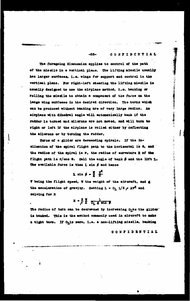
The foregoing dieeussion applies to oontrol of the path
of the missile la s vertical plane. The lifting missile usually
hss larger surfaoes, i.e. wings for support and oontrol in ths
rertioal plane. tor right-left steering the lifting missile is
usually designed to use the airplane method, i.e. banking or
rolling the missile to obtain a ocnponont of the foroe on the
large wing surfaoes in the desired direotion. The turns whiob
oan be produoed without banking are of very large radius. An
airplane with dihedral angle will automatically bank if the
rudder is turned and ailerons are not moved, and will turn to
right or left if the airplane is rolled either by deflecting
the ailerons or by turning the rudder.
Turns of a glider are deaoendlng spirals, if the in-
clination of the spiral flight path to the horizontal is •, and '
the radius of the spiral la i, the radius of curvature R of tbe>
flight path is r/oos e. call the angle of bank fi and the lift X,.
The available force is then L sin 0 and henee
1 sin * - | £
Y being the flight speed, w the weight of the aircraft, and g
the acceleration of gravity. Setting L - CL 1/2 /• AV* and
solving for R B . B W 1
fH Cj, g sin a1
The radius of turn oan be decreased by increasing Cjaa the glider'
is banked. This is the method commonly used in airoraft to make
a tight turn« If Ojis sero, i.e. a non-lifting missile, banking
COHFIDSNTIAL

-36- CONFIDBNTIAl
doe» not give rise to a turn» H being infinite. If CL ia not
zero, i.e. a lifting missile, banking gives rise to a turn even
if C* ia not inoreaaed by aotion of the longitudinal oontrol.
This ia one of the essential differences between the aerodynamio
properties of lifting and non-lifting missiles. We shall diaouM
further the right-left stearing of lifting missiles by banking
in the section on ooupling of oontrola.
It la quite possible to design a lifting missile whioh oould
turn without banking. A large vertical surface would be needed
and various praotiaal difficulties-arise.
Kon-lifting missiles will probably have leas difficulty wits
compressibility effeota at high speeds. The chief difficulty
with the lifting missile arises from the faet that the missile la
unsymmetrioal about the plane of the wings and the orientation
is maintained by reaotions on wings and tall whose momenta about
the oenter of gravity are equal and opposite. Compressibility
effects first appear on the wings, usually producing diving
momenta and large ohanges in attitude. The non-lifting missile
on the other hand ia symmstrioal and both body and fin moments
are aero exoept when oontrol ia applied. Thus the trim position
of the non-lifting missile is not likely to ohange with speed
in the abaenoe of oontrol. The oontrol will undoubtedly ba
modified by compressibility effects.
At the prnsent time aerodynamio data at auperaonlo speeds are quite limited, oonalating mainly of Information on the drag
CONFIDENTIAL

•'ig|%JSSffHHBWMB!W,^|W^!1.''^ *< ^^"V^rtnt^nt^^ntu-K»»
-37- • >
CONFIDENTIAL
of projeotiles obtained In firing tests. Adequate supersonlo
faoillties are now being provided and within the next year or
two a great deal of the necessary baaio research should be
completed.
Powered Missiles.
The oontrol of powered non-lifting missiles requires little
further discussion. When no oontrol is applied, the propulsive
force acts in the direotion of motion, variation of the pro-
pulsive foree ohanges the speed but not the direotion of motion.
When oontrol is applied, the orientation may ohange, in whioh
ease the propulsive force has a component at right angles to
the direotion of motion of the oenter of gravity, increasing the
lateral farce available for oontrol. This sffeot is usually
not large.
In the case of powered lifting miaalles, variation of the
propulsive force constitutes a seoond and independent method
of oontrol in the vertical plane. Under equilibrium condition«
the speed is approximately independent of the value of the
propulsive foroe, satisfying the equation
_ 8W ooa a
For horizontal flight the propulsive thrust T is equal to the
drag 0. If T ia greater than D the missile climbs at angle e
such that T - D + W sin 9. The angle 9 may be negative corres-
ponding to desoent if T is less than D. For more oomplete
disouasion reference should be made to one of the many books
CONFIDENTIAL
MHjlinWJ r •"-"•fr"-"- «*•••*

-38- OtfVXOSHTIJkL
OB the subject or airplane performanoe.
Homing Klssllea.
In homing missiles, the apparatus contained within too
missile looatea the target with reference to some axis fixed
in tha aisaila. Tha information ao obtalnad ia not adäquat« am«
lasa this rafaranoa azia ia alwaya in a known relation to tha
flight path of tha oantar of gravity of tha mlaaila. Ina
almplaat solution la obviously to make tha rafaranoa axis Minolta
with tha flight path, i.a. to have tha intelligence davioa "look*
•long tha flight path. Tha installation is sspaoially staple
if tha application of oontrol does not ohnnga tha orientation
of tha miasila with raapaet to ita flight path. Tha aeouring
of thla result is ono of tha aerodynamio problems peculiar to
homing missiles. Tha solution usad in tha Palloan and Bat projaosa
was to ohanga tha lift of tha wing by trailing edge flaps and
to ao looata the oantar of gravity of tha mlaaila and a flxad
tall struoture that tha downwash sffeota on tha tall produoad
momenta counterbalancing tha moments produoad by tha flap
defleotion. The Roc projeot adopted tha same solution.
In tha flight of an unpowerad homing mlaaila in still air -
against a stationary target, the flight path is approximately
rectilinear. The initial apeed la usually much less than the
terminal apaed in the straight glide path and hanoe the speed
increases. To maintain tha reotllinear flight, tha lift muat
be maintained constant and equal to W cos ». As tha speed in*
oreases the lift ooaffioient must be deoreased by the notion
CONJIDBHTIAt

«r -39- CONPIDBNTIAL
of the oontrols.
It appears desirable to operate unpowered homing missiles
within the range of lift coefficients lying between zero and
that for maximum lift-drag ratio. As is well known the equi-
librium flight path first flattens and then steepens as the lift
ooeffloient is increased. There is accordingly a reversal of
control as regards the final, effect when past the maximum lift-
drag ratio. Missiles are not usually in equilibrium on their
flight path, and computation shows that the first effect of
oontrol is always that of the change in lift. If however the
lift-drag ratio at the maximum lift coefficient permitted by
the controls corresponds to a slope of path steeper than the
aotual path slope to the target, the oontrol prooeeda to Its
limit and stays there. The intelligence oalls for a higher lift.
A higher lift coefficient Is obtained as the oontrol moves
toward its limit but also a higher drag coefficient. The drag
reduces the speed so that the aotual lift does not inorease vary
fast and the flight path oorreots very slowly, if at all. It
is probably desirable that powered homing missiles should also
be operated in the region between zero and maximum lift-drag
ratio.
If the homing missile Is powered« various combinations of
oontrol «re possible. For example, the propulsive thrust might
be controlled by a speed-sensitive devloe to maintain a constant
speed in the later stages of the flight.
CONFIDENTIAL
«,-«•<•.. ..,..**...;»..-

•*•**;* WTjfüJ-r- *, ..
-40- CONFIDBNTIAL
Stability Problems«
In theory a houing missile might receive sufficient oontrol
information to give stable flight without inherent stability of
the missile in the absenoe of oontrol. In praotioe, a missile
must have satisfactory stability to maintain its flight in periods
of intentional or unintentional absence of oontrol information.
It is not practical to review the many aspects of the
stability of missiles. The disturbed motions of a stable air-
plane-like missile in the absenoe of homing oontrol consist of
various combinations of a rapid heavily damped longitudinal
motion in which the angular pitching motion is most prominent;
a slow osoillation. the previously mentioned phugoid oscillation«
in which the missile rises and falls with the speed decreasing
and increasing; a rapidly damped rolling and yawing osoillation;
and a slow spiral motion.
Under certain conditions the missile may pass from steady
rectilinear flight to a steady spin, in a true spin« as dis-
tinguished from the spiral motion referred to above, the wing
surface is stalled, i.e. meets the air at a large angle. The
spinning motion is however a steady motion with the following
balance of moments and forces;
1. The stalled wing rotates of itself at suoh a speed
that the rolling moment is zero. (A wing at normal .
angles offers resistance to rolling; a stalled wing
is in unstable equilibrium at zero rate of roll).
CONFIDBNTIAL

Jr. At
"41- . CONFIDENTIAL
26 The aerodynamic pitching moment, tending to reduce
the angle of attack is balanced by the centrifugal
pitching moment tending to increase the angle of
attack,,
3. The aerodynamic yawing moment is balanced by the
centrifugal yaiving moment. The spinning character-
istics ere greatly affected by the angle of yaw at
which this balance occurs.
4. The airplane descends at such a rate that the vertical
component of th© air force equals the weight.
5. The horizontal component of the air force gives one
requisite centripetal acceleration of the center of
gravity towards the spin axis»
A raiasile can be made difficult to gpin by a suitable dis-
position of tail,surfaces to give large aerodynamic pitching
moments and a favorable anti-spin equilibrium angle of yaw.
When a homing device is applied to an airplane like missile»
the disturbed motions take on a somewhat different character.
For example, considering only the longitudinal stability, the
slotf phugoid oscillation disappears and is replaced by a damping
of any disturbance of the velocity alqng the flight path, the
period and damping of the fast angular pitching-oscillation are
controlled in part by the static longitudinal stability of the
missile and in part by the power of the control surface and the
lag of the eervomechanisa, and there arises a second angular '
CONFIDENTIAL
X*-ij.\lJ;-.-4
-48- CONflDENTIAL
pitching osoillatlon of longer period which may in some oases
degenerate into two aperiodic motions. As the missile approaches
the target, the frequencies and damping constants change some-
what and an additional mode appears.
In a similar manner the slow spiral motion associated with
the lateral stability of the free flying missile disappears.
There are short and long period oombined rolling and yawing
osoillations where damping may be positive, zero, or negative
and the long period motion may degenerate into aperiodio motions«
Soroa aspects of the stability of homing missiles will be
discussed briefly in the seotion on System Stability or Hunting
problems.
IV. Coupling Between controls
Interdependence of controls.
A missile In flight has six degrees of freedom but If It
follows conventional aircraft design it has only three controls
unless it is propelled in whioh oase It has also a throttle or
equivalent thrust oontrol. The three oontrols are usually
movable surfaoes to oontrol the moments about three mutually
perpendicular axes and there is no dlreot oontrol of the linear
motions. Unfortunately the three oontrols do not give independent
effects. Thus the rudder produoes a small rolling moment as
well as a yawing moment whioh turns the aircraft to right or
left. When yawed, there results a muoh larger indireot rolling moment arising from the aerodynamic reaotions. The ailerons
OONFIDBNTIAL
*.mmm*»-****tot*****f*»*«

-43- C0NFID3NTIAL
produce yawing moments as wall as rolling moments and the yawing
moments may be "adverse" i.e. the resultant yaw produces a
rolling moment in a direction opposite to the desired rolling
moment or they may be favorable. In extreme cases the ailerons
may turn the aircraft to right or left without rolling it or
the rudder may roll the aircraft with little yaw. The effeots
may ohange sign for the same airoreft at different speeds i.e.
at different angles of attack or at different lift coefficients.
The interaction between the rolling or yawing motion and the
pitching motion is fortunately vory small.
In the oaae of non-lifting missiles, operation of the left-
right and up-down controls simultaneously produoes rolling
moments and hence it has been found that a non-lifting missile
must have ailerons if rolling motions are to be avoided.
Correspondence between Intelligence Coordinates and Controls.
The intelligence devices generally available for use in
homing aeromissiles give information on the bearing of the
target to the right or left and up or down from some reference
axis, i.e. an essentially two-dimensional presentation, in
the case of radar devices, range information can also be obtained
If desired. The missile however has three controls if un-
propelled and at least four If propelled. There is evidently
a problem In making connection between the two-dimensional out-
put of the intelligence device and the control system of the missile.
COKFIDKNTIAL

-44- CONFIDENTIAL
In the case of a non-lifting missile, the obvious method
of connecting the controls is to connect the two channels of
the intelligence device to t.wo control surfaces producing
moments about two mutually perpendicular lateral axes which are
aligned with the intelligence device, v/hile the two control
surfaces may be designed to give independent action about the
lateral axes, the application of control about both axes
simultaneously will produce rolling moments about the longi-
tudinal axis, . if the aerodynamic design were such that the
longitudinal axis remained in the direction of motion, the roll
would not be objectionable unless the rate was so high that
the lag in the control system introduced phase errors. However
most missiles of the zero lift type change orientation as the
controls are applied. The roll takes place about the axis
of the missile and introduces incorrect error signals in the
intelligence device. The better solution is to stabilize the.
missile in roll by means of ailerons controlled from a suitable
gyro system. Thus in the simplest method, the roll control is
governed by a gyro, and thu other two by the channels of the
intelligence davice.
There have been many ingenious suggestions for connecting
the controls of a non-lifting missile to permit continuous
rotation of the missile, it does not seem profitable to discuss
them here. For remotely controlled as distinguished from homing
missiles such devices become computers, often of complex design,
.CONFIDENTIAL

-46- COKFIDKKTIAL
for transforming from fixed to rotating axes, and metering the
degree of control to be given by each of the two oontrol surfaoea.
In the case of a lifting missile of the airplane type,
turns are accomplished by banking the airplane and it is not
therefore desired to prevent roll. It is neoessary either to
reduoe the number of control surfaces from three to two or to
couple two of the oontrol surfaces together to be controlled
from a single intelligence channel. If the missile is powered«
the throttle or equivalent power, plant oontrol may be arranged
to be controlled by airspeed, altitude, or some quantity
associated with engine performance as for example mixture ratio»
peak pressure, temperature, etc. Combinations may be used
but it has not been customary to use the throttle for up-down
oontrol of the flight path.
The more common two-control airplanes use the elevator-
rudder or the elevator-aileron combinations. Both methods have
been used in the design of missiles. With proper design reason-
ably satisfactory turns can be made either with ailerons or
with rudder. For homing missiles, aileron oontrol is believed
to give somewhat smaller errors, since out-of-trim rolling
moments can be balanoed without introducing yaw. in either case,
the use of two oontrols alone makes possible independent
connections of the two intelligence channels.
It has already been pointed out that a gyro is required
for trimming the missile in roll. It is desirable that this
C0NPID3NTIAL
M**: j B. jfttfSiN
9, 1 1
-46- CONFIDBNTXAL
gyro also limit the maximum angle of roll; otherwise the missile
Is likely to turn over on its back when a control signal is
continued for some time.
In automatio pilots for aircraft, the rudder and aileron
ere often controlled together for turns. Such a coordination
is possible for one or at most a narrow range of flight con-
ditions. For missiles intended to operate over a considerable
speed range, the rudder displacement for a given aileron dis-
placement varies, both with airspeed and angle of attaok, and
it has not seemed necessary to attempt the design of the
neoessarily complicated oontrol. By suitable aerodynamic design
of a two-control missile, the side-slip during turns can be mad«
reasonably small.
Bffect of Roll on srror Signals.
The lifting missile of the airplane type banks during a
turn. The reference axes of the intelligence device are fixed
with referenoe to the missile and hence rotate with the missile«
The axis of rotation of the missile does not usually ooinoide
with the direotion of motion of the oenter of gravity of the
missile. Henoe the intelligence devioe no longer measures the
up-down and right-left errors with respect to axes fixed with
respect to the vertioal.
It has been previously pointed out that an airplane is
made to turn in its tightest olrole by banking and then pulling
back on the stick to increase the lift coefficient to its
OOIIISlIIIil

-47- CONFIDENTIAL
maximum value. The coupling between the up-down and right-left
controls produced by banking automatically gives an error signal
to tne elevator or elevons in a direction to increase the lift
coefficient, and thus accelerates the turn. At the same time
the increased lift bends the trajectory of the center of gravity
upward. Tne exact behavior of the system depends on the
characteristics of intelligence device, servo-mechanism, and
missile.
The error angles are readily computed for idealized motions»
If the missile rotated about the direction of motion of the
center of gravity, the effects amount simply to rotation of the
axes of referenoe of the error signals. If the error angles
referred to the original axes are &• in elevation and SA In
azimuth, and If referred to axes rotated through an angle (f
St and &( we have the relations
£ » 4".co8 0 - Sr sin &
St' » i^ain f> «• ft oos $
If however the rotation occurs about an axis making an angle (?m
with the direction of motion of the oenter of gravity
gj~ •", cos 0 - (£ -ft.) sin fi
£,' - (, sin A + (i, - S».) oos ff
In the general case the dynamics of a rigid body with six
degrees of freedom and the aerodynamic characteristics of the
control must be considered. Thus the axis of torque varies with the displacement of the oontrol surfaoes. The body rotates
CONFIDENTIAL
i>,f*»s: »•*««.-vfv*;**'"'-:
-48- CONFIDBNTIAL
not about the axis of torque, unless this axis is also a principal
axis of inertia, but about an axis intermediate between the
axis of torque and a printsipal axis. Thus the instantaneous
axis of rotation travels in the body and an integration prooess
is neoessary. Beoause of these complications it is not very
practical to correct for these effects by inserting a computing
device between the intelligence and the controls. One of the
important consequences of the foregoing effect is that when
there is an elevation error angle and the true azimuth angle
is zero, an azimuth error is passed on to the controls equal to
-( 5( - St. ) sin 0. To fix ideas suppose that the target is high
so that St -£ruis positive and that the airplane rolls as for
a right turn (positive 0). A negative azimuth error is than
given to the controls, which tends to oppose the right turn.
If however & - &.were negative, i.e. true elevation error zero
but axis of roll above flight path or target is low, the azimuth
error given to the* controls would assist the turn. In the first
case there would be a damping effect on osoillations; in the
second a destabilizing effect which would promote hunting. In
the usual lifting missile the effect is on the average a de-
stabilizing one.
Sffeot of Angle of Attaolc or Yaw on Krror Signals.
In the non-lifting missile, the application of controls
pitches or yaws the longitudinal axis so that the intelligence no longer looks along the flight path. Using the same notation
t -a
CONFIDENTIAL
-..«**! w* . •••-,-*»t**-i*rf*l?:(^ia*V.-S»iAiii*.-^

-49- CONFIDBNTIAL
aa before, the effeot Is given by the relation
The same relation applies to the elevation control of a lifting
missile, it is in theory possible to interconnect the controls
with the intelligence device to move the reference axes of the
intelligence device to compensate for this effeot. If under-
compensated there will be a stabilizing action against
oscillations and if overcompensated a destabilizing action.
Methods of Reduoing Coupling Between Controls.
The methods of reduoing both the interdependence of the
controls and the undesired effects of the angular motions on
the error signals are still in the early development stages
and much additional aerodyne a researoh is required. A horing
missile oa -i made to worn .nth all tnese effects present in
some degree, it would seem fruitful however to attempt to
make the normal flight path ooinoide with the longitudinal
principal axis of Inertia, for all control positions, and to do
further research on reduoing interactions between controls.
V. system stability or Hunting problems.
Illustration of Hunting.
Perhaps the most difficult of the special problems associated
with the design of homing missiles is"that of securing a satis-
factory stability of the oomplete system, sinoe the overall
stability depends oa the characteristics of missile, intelligence,
and servomeohanism and especially on their interrelations. To
C0JIFID3NTIAL
^ *****. .A,-^

-50- C0NFID3NTIAL
illustrate the problem there are shown In Figs. 2, 3, and 4 the
observed motions of three homing missiles. In Fig« 2 it is seen
that the missile rolls and yaws in increasing oscillations of
about 10 seconds period until the missile strikes the ground.
In extreme oases such a missile may turn completely over on its
baok, lose track of the target and descend in a steep spiral,
in Fig. 3, the missile pitches in a steady oscillation of nearly
constant amplitude and from 5 to 7 seconds period. Figure 4
shows a rolling and yawing oscillation which is damped as the
flight progresses. The period of the main oscillation is
approximately 10 seconds but there is superposed a rapid- roll
oscillation of about 4° amplitude and 1 1/4 seoond period.
The steady hunting motions illustrated in Figs. 3 and 4
are objectionable only in so far as they affect the path of
the center of gravity of the missile. The unstable motion of
Fig. 2 usually but not always results in complete failure of
the missile and a wide miss.
The effect of a given hunting motion on the trajectory may
be estimated as follows. The error angle is equal to the ratio
of the velooity dy/dt of the missile transverse to the flight
path to the velooity V of the missile, provided the missile
looks along its flight path. If- this angle oscillates slnu-
soidaliy with maximum amplitude 80, the motion may be represented
by
£ V0o cos 2*rt
CONFIDENTIAL
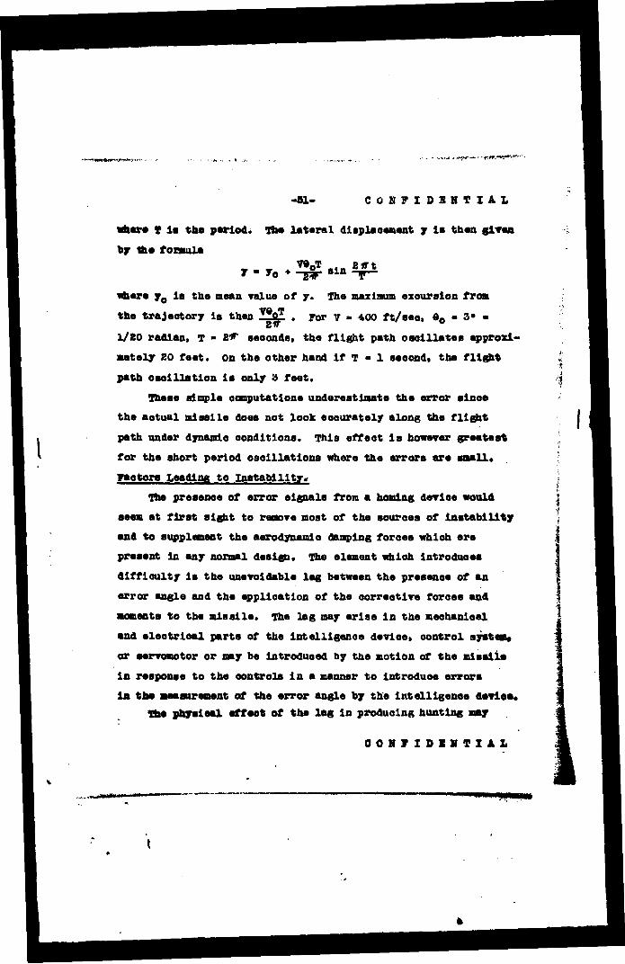
P-.«. , .-,rm-ws-«V'
-61- C0N7XDBNTIAX.
«bar« T is toe period. The lateral displacement y la then given
by the formula V»0T 2»rt
«here y0 la the mean value of 7. The maximum excursion fron
the trajeotory is then ZSfiZ . For 7 - 400 ft/seo, ©0 - S» -
1/20 radian, T - W seconds, the flight path oscillates approxi-
mately SO feet, on the other hand if T - 1 seoond, the flight
path oscillation is only 3 feet.
These simple computations underestimate the error sinoe
the aotual missile does not look aoourately along the flight
path under dynamio conditions. This effect is however greatest
for the short period oscillations where the errors are small«
gaotora Leading to Instability.
The presenoe of error signals from a homing devioe would
seem at first sight to remove most of the sources of instability
and to supplement the aerodynamio damping foroea which are
present in any normal design. The element which introduces
difficulty is the unavoidable lag between the presenoe of an
error angle and the application of the corrective forces and
momenta to the missile. The lag may arise in the meohanloal
and electrical parts of the intelligence device, control system»
or servomotor or may be introduced by tne motion of the missile
In response to the oontrols in a manner to introduce errors
in the measurement of the error angle by the intelligence device. The phyaloal effeot of the lag in producing hunting
OOHIIDlITIil
e«M|
•88- C0N7ID3NTXAL
bs spprecieted by considering the mis«1la displaced from tb»
correct flight path toward the target but being returned to It
by the aetlon of the oontrols. Aa the error angle approaohea
sero, the oontrol aurfaoe defleotlon la approaohlng zero and
should reaah zero at the same Instant aa the flight path Inter«
sects the target. Or If the oontrol *.a of the on-off type«
reversal should ooour at the Instant tf?e flight path Inter-
sects the target, if thla oouldooour, the aerodynamlo damping
foroes would abaorb some of the kinetic energy present and the
next orossings would ooour with successively decreasing speed
until the missile reaohed equilibrium on a steady trajectory«
Beoause of the inevitable lag present, the oontrol surface
remains deflooted in a dlreotion to lnorease the error angle
of the missile for a abort time and tjus feeda energy into the
osolllatory motion. SQuilibrium is reaohed at an amplitude of
osoillatlon such that the amount of energy fed in is equal to
that absorbed by the aerodynamlo damping. It may happen that
the equality of energy fed in and absorbed does not ooour for
say amplitude, in whioh oase the osoillatlon builds up until
the missile oapslses.
She amount of energy fed In is directly proportional to the
time lag, and to the overall sensitivity i.e. to the magnitude
of the correcting foroes and momenta produced by a given error
angle. This overall sensitivity is dependent on such faotors •s the area of the oontrol surfsees, the speed, altitude, and
CONFIDBHTIAL
1

-S3- CONFIDBNTIAL
attitude or the missile, the deflection or rate of deflection
of the oontrol surfeoe for a given electrical input to the
servomeehaniam, and the sensitivity of the intelligence devioe.
The aerodynamic damping is a function of altitude and
airspeed as well as of relative areas of various parts of the
missile and of the amplitude of oscillation.
The time lag in the intelligence device is usually determined
by the amount of integration or smoothing found desirable to
give a reasonably steady output signal from the intelligence
devioe. For the radar homing systems used so far, the time
lag has been within the range 0.05 to 0.25 seoonds.
The time lag of the . ' tiii electromechanical servo system
is of the order of 0.10 to 0.15 seoonds, but considerably smsllw
values can be obtained by special design.
Blther a time lag or a time advanoe may be introduced by
the relations between the motions of the missile, the axis of
the intelligence device, and the direction of motion of the
oenter of gravity of the missile as disoussed in the seotlon
on the effeot of roll on the error signals. Far the usual
design of missile the axis of roll lies between the longitudinal
axis of the missile and the direction of motion of its oenter
of gravity and a time lag is introduced. Thus if a disturbance
rolls the missile say for a right turn, a false azimuth error
Is indicated in a direotion to aid the turn and amplify the
effeot of the disturbance. Or from the point of view of lam.
CONFIDSNTIAL

-84- CCN*IDHI<T!AL
IT the missile is off course to the left and correcting to too
right, the centering or reversal of control is delayed until
the missile moves off oourse to the right a sufficient amount to
bring the rotated reference axis on the target.
The use of autotaatio lead computers to reduce errors
associated with wind and moving targets often leads to a diffleult
stability problem as discussed later in this report.
Anti-hunt Devices.
Sinoe hunting is evidenoe of a phase lag between the error
angle and the application of corrective foroes and moments, th«
remedy is obviously the introduction by some means of a phase
advanoe «dich is greater than the lag. As the missile oomes on
oourse, the control must be reduoed or removed before the error
is actually zero. The most common method of aooonplishing this
result is to incorporate a rate term In the oontrol, i.e. to
make the position or speed of the oontrol dependent in part on
the error and in part on the rate of change of the error.
A compensating or anti-hunt oirouit can often be introduoed
in the amplifier or output oirouit of the intelligence devioe
Itself, it usually takes the form of a suitable condenser»
resistance network which may be considered either as a phase
advanolng devioe for sinusoidal signals or as introducing • rsto
component for arbitrary signal variation. Difficulties often
arise with such a oirouit if the input signals are "rough", i.e. fluotuating in magnitude for a given error angle as for example
OOKFIDIHTI.At

1 '•• m««wniu>«>»vk~~
-88- * » CONFIDENTIAL
is ths oaae for radar reflections from many types of targets.
Beoause of the antihunt oirouit, the higher frequenoy "roughness"
is amplified muoh more than the slower variation as the missile
oomes on oourse. A further characteristic of this anti-hunt
oirouit is that good performance is obtained only with consider-
able attenuation of the input signal so that additional amplification
is required.
The rate term may be introduced by a gyroscopic turn
indicator which measures the angular rate at whloh the missile
oomes on course. This method has been found completely effeotiv*
in obtaining system stability, it has ths disadvantage that
winds or moving targets require a steady rate of turn whioh
introduces a control signal. The presenoe of this signal in
effeot limits the maximum rate of turn and thus lnoreasss the
errors associated with winds and moving targets.
Time to Come on Course.
Ons of the characteristics of the oontrol system of interest
is ths time required for a missile released with an Initial error
angle to come on its proper oourse. The time can be controlled
to some extent by the overall sensitivity of ths oontrol system.
It has already been pointed out that increasing the overall
sensitivity lnoreasss the amount of energy fed into the system i
when s time lag is present. Even if the system is stable, ths
miss!is may come on oourse with a damped osoillstory motion and i
ths damping is small if ths sensitivity is too great. A return
CONFIDBNTIAL
\
w*iTimnrniTHmi .
'^WSKW-^^ftWrtWWjmyl^.^.. - jrrfKpfjf *'
-86- 00IMDI1IIAI
I
without oscillation oan be scoured with suitable values of the
control parameters. Both ezperieaoe and theory show that It 1*
necessary to male« a compromise between the stability character*
lstios and the time to oome on eourse. In aost oases it is
neoessary to Bake the tlae to oone on oourse a matter of the
order of 10 seconds or aore.
«ffoot of Wind Ousts«
Wind gusts lntroduoe disturbances which excite the natural
•odes of motion of the oomplete system. The effeots persist for
times which depend on the periods or time oonstants of the
natural modes, and the disturbed motion at any Instant depends
on the history of disturbances over oomparable past periods of
time. Bxcluting the effeots of ohangea In speed along the tra-
Jeetory for which the time constant is very large but-which in
themselves do not oause the missile to ales the target» there
usually exist modes for whioh the time oonstant is of the order
of 10 seeonds. Hence gusts in the latter part of the flight
path lntroduoe errors whioh oan not be wholly eorreoted in the
tlae available..
experience has shown decreased dispersion In tests of hoalni
missiles over water as compared with tests over land which is
probably to bs attributed to the decreased gustlnsss over water.
In one instance over land, a severe disturbance was noted from
the sharp boundary between a heated layer of air at the ground
and a cold air aass aloft. While the designer of a alsslle oan
-•i
4 s
OOiriDIKIAl

•57- OONIIDINTIAI
vary tue frequencies of the natural modes of motion through «nail
Halts, it is preotloally lmpoaeible to change their order of
magnitude, jfortunately tha arrora in the trajeotory daoroaaa
aa tha raotlllnaar flight apaad inoraaaoa.
Mathoda of Analyala.
Tha problam of tha design of atabla systems has bean
approached by several mathoda of mathematioal analyaia and by
ezperlmenta on meohanioal, electromechanical, or alootrloal
models, if auffioient information la available from taata of
the oomponent parts, the 'ohoioe of oontrol parameters to assure
ayatam atability can be made by any of these mathoda of analysis.
Tha purely mathematioal methods require more or leas Idealised
representation of the performance of tha oomponent parts of the
system and are moat useful for systems «hose performance is
desorlbed by linear differential equations. The various methods
using models hare tha advantage that.some of she aotual com-
ponents can be incorporated aa part of the model, so that non-
linear oontrol mechanisms and on-off or step oontrols whose
mathematioal analyala is often dlffloult can readily be inves-
tigated.
The oontrol ayatam of a homing missile constitutes a
oloaed-oyole oontrol system or servomaohanism. The chief differ-
ence from ordinary servomeohaniams is that the parameters of
the system are not constant but vary through considerable limits
during the flight of a single missile. More speoifioally the
OORIISlITIAl

r •BB- dONTIDUIUL
parameters essoo.uted with aerodynamic foroes and moments aro
funotions of the air speed, air denalty, and attitude of the
mlaalla and lta control aurfaoea. if theae varlatlona are taken
Into aooount, the usual methods of analysis of aervomeohanlams
nay be applied. Theae Involve a study of the reaponae of the
system to oar tain standardized conditions, the two moat useful
conditions translated in terms of a homing missile being a sinu-
soidal displacement of the target at various frequencies or a
sudden permanent displacement of 'the target. If the system is
a linear one, its performance la completely known when the per-
formance under either of the above conditions is known.
Headers who are Interested in the details of the mathematical
prooedurea are referred to th» restricted paper by A. C. Hall
of the Servomeohanisma Laboratory, Massachusetts Institute of
Technology, entitled "The Analysis and Synthesis of Linear
Servomeohani-sma", Technology press, 1943. This paper describes
the application of the sinusoidal analysis to the design of
linear servoaeohanisms with continuous control. An example of
analysis using suddenly applied disturbances may be found in
Restricted Technical Kote No.*1 809 of the National Advisory
Committee for Aeronautics by F. H. Unlay entitled "The Theoretical
Lateral Motions of an Automatically controlled Airplane subjeoted
to a Yawing Moment Disturbance". Robert T., Jones of the same
laboratory has developed this method of study of the oontrol
of ear«sin types of missiles.
OONTXDSHTXAL

• •.«*BWi#flHtt* •<
•59- CONFIDBNTIAL
The preceding methods of analysis lend themselves to a
oomplete study of the performance of the system, including not
only the question of whether the system is stable or not but
all questions of the magnitude of the errors. For determination
of stability, one may apply the method of email oscillations
commonly used in airplane stability problems. This method as
applied to an airplane without automatic pilot is described in
great detail by B. Uelvill Jones, in Division N. Vol 5 of
Durand»s Aerodynamlo Theory under the title "Dynamics of the
Aeroplane". The method in effect determines the period and
damping of the natural modes of oscillation and the damping of
the natural aperiodic motions, if the damping constant turns
out to be negative, the corresponding mode is unstable.
The mathematical«methods are in praotioe limited to systems
described by linear differential equations and find some
difficulty in the treatment of aotual servo systems with friotion,
"dead" regions, and time lag. For this reason models have been found useful. These range in complexity from systems repre-
senting a single degree of freedom of the missile to more complete
flight tables which include the three angular components of the
motion at the "phantasmagoria" which simulate one or two
components of the linear motion. As an •example, methods of
automatio roll stabilization may be investigated with the aotual
gyro and servo elements by using a mechanical system (damped
pendulum or damped rotor) to simulate the inertia and damping
CONFIDBNTIAL
IW-- • -iti**!***; iuij*+>3*~i'+*'~4*lfi***i' * •MM
-00- cc ,< 7 i o n T a i
of the miasile about Its roll axis. A system of this type as
wall as a more complicated electro-mechanical model of the
longitudinal motion were used in the study of the pelloan and
Bat control systems. In addition. Or. A. C. Hall of the Servo-
meohaniams Laboratory, Massachusetts institute of Technology,
developed a flight table in which the pitching, yawing, and
rolling motions of the missile with proper cross coupling war«
fully simulated and on which an overall test could be made of
the complete control system lnoludlng intelligence unit, gyro-
scopes, and aervomeohanism. This flight table was extremely
useful in determining the bast adjustments of the several,
parameters of the oontrol system.
Experience with these modal methods and comparison with
actual flights of homing missiles show that the models reproduce
the angular motions encountered In flight extremely well.
Designers of homing missiles will find that the use of this
method of studying system stability and overall performance will
save much time In the development of a stable system and In
adjusting it for best performance.
VI. Problems arising from wind and Moving Targets.
Pursuit Curves
If the target is moving or there is a natural wind, a flying
missile which always heads toward the target follows a path
known as a pursuit curve or homing curve depending on whether
the motion Is referred to the air or to the ground. The pursuit
CONTIDBKTIAL
-61- CONFIDENTIAL
ourve has the characteristic that the radius of curvature becomes
•cry small as the target is approached and beoomes infinitely
small for the idealized case of a point target. The maneuver-
ability of the missile is limited and hence the missile will not
hit a moving point target or a stationary target in a cross
wind. The magnitude of the miss depends on the speeds of the
missile, wind, and target and their relative directions, on the
range, and on the maneuverability of the missile as expressed
by its minimum radius of curvature.
This problem in idealized form has been studied by the
Statistical Research Group, Division of War Research, Columbia
University, under the direotion of the Applied Mathematics panel.
For convenience the effect of wind and target motion are combined
to give an apparent target motion of speed v. (See Figure S). The
azimuth <K of the launching position referred to the direotion
of apparent motion of the target, the launching radius r0, ^he
ratio n of the apparent target speed v, to the speed of the
missile V, and the minimum turning radius /=, of the missile are
the quantities determining the miss for the oase of point target.
Constant velocities of target and missile, direotion of launching
toward the target, and missile continuing along an osoulating
circle when the minimum radius of curvature is reached are
assumed.
The oomputed miss M is shown in Figure 6 in the form of
a plot of Ufa, TS ft 'or n - 0.1, 0.8, 0.3 and 0.4 and r0 - 6/5;,
CONFIDENTIAL
jfc, ....*-~
-•jams****
-62- CONFIDBNTIAL
10/*i and 14/» . The essential points to notloe are (1) that the
maximum miss varies but little with launching radius; (2) that
the maximum miss is approximately equal to 1/Z&,a and (3) that
the miss becomes very small for <£ between 140s and 180°. The
only factors within the control of the designer of the missile
are the speed of the missile and its minimum turning radius.
The speed ratio should be as small as possible and the minimum
turning radius as small as possible to minimize pursuit curve
errors. The user of the missile may reduce the error by making
his attaok on a course such that <£. is approximately 145°. in
the oase of ship targets this oourse gives a good compromise
between the magnitude of the error and the projected length of
the ship which determines the permissible error whioh still
yields a hit.
Computers.
The essential feature of the pursuit curve is that the
missile moves along a path whioh makes an angle tan-1 n sin 6. JL+n COS*),
with the line Joining the missile and target. Jf the axis of
the intelligence device were rotated with respect to the longi-
tudinal axis of the missile by this amount in the opposite
direction to the apparent target motion, the path with respeot
to axes fixed in the target would be straight and the missile
would travel on a "collision" oourse. If the user of the missile
has the necessary data to compute n and 41, » and the means of
offsetting the axis of the intelligence device by the oomputed
1 * .'i
•I
CONFIDENTIAL

-6S- CONFIDENTIAL
amount and If the variations of n and 4>0 nay be neglected, the
pursuit ourve error may be eliminated.
It is in theory possible to design a computer which auto-
matically offsets the axis of the intelligence device by the re-
quired amount. The simplest soheme in theory is to equip the
intelligence device with a separate servo system which always
keeps the axis of the device centered on the target. If the
missile flies a collision course the bearing of the target will
remain constant and hence the angular velocity of the intelligence
devloe will be zero. If the controls are so arranged that the
missile is guided to make the angular velocity zero, the course
followed should be the desired collision oourse. in practice a
high preoiaion is required sinoe the rate of change of bearing
for a small offset is very small at long ranges. Furthermore
the missile is subject to numerous disturbances of attitude and
it appears that an aoourate linear integrating angular velooity
meter would be required. It is not known whether the soheme
would work or not; it has not yet been tried on a missile.
Another possibility wfaioh amounts to Integrating the angular
velooity is to determine the angular displacement of the axis of
the missile after a certain time or distance by means of a free
gyro Which maintains a fixed direotion In space. A knowledge
of the angular displacement and the range at the beginning and
end of the displacement penults a computation of the desired
offset. This computation also assumes a constant value of n
CONFIDBNTIAL
^WWteesMMllMH

y. -64- OONFXDSNTIAL
throughout the flight.
Still another possibility is a continuously integrating
angular velocity meter which continuously sets in the appropriate
offset.
Jtudy shows that the roughest sort of correction reduoea
the pursuit curve errors even though a true collision oourse is
not obtained. Hence it is worthwhile to experiment with the
simplest conceivable computers, for example those dependent
merely on the relative frequency and length of error signals In
the two opposite directions.
The chief bar to the general use of computers lies In their
effect on system stability and in fact the automatio devioes
desoribed can not be used because they produce excessive hunting.
The oomputer essentially puts in a lead on a moving target. If
the missile as a result of a disturbance rotates to increase the
lead, the angular velocity developed aots to increase the lead
still further and thus builds up an osoillation of increasing
amplitude. The oomputer can not distinguish between angular
velocity arising from disturbances and angular velocity caused
by the missile following a pursuit curve. An automatic lead
computer is an inherently destabilizing device.
The two methods of solving the stability problem are (1)
to feed in only a fraotion of the oorreot lead angle or (2) to
introduoe a time oonstant in the integration process whioh is
long compared to the natural periods of osoillation of the
CONFIDENTIAL

-65- CONFIDBNTIAL
boning mlseil«, in the first ease the permissible fraotion is
dependent on the stability reserve of the complete system of
intelligence devioe, servooontrol, and missile. In the seoond
ease the time constant must be of the order of at least 20 or
30 seoonds for missiles exhibiting natural periods of the order
of 1 to 8 seoonds»
The computer problem is susceptible of mathematical analysis
for any specifie missile and control system, and is not too
diffioult if all elements of the system are linear. Actual
experience with oomputers on a homing missile is not yet available.
VII. Bore Sight Errors.
If the axis of the intelligence devioe does not ooinoide
with the direction of motion of the center of gravity of the
missile, there arises an error which may be termed the bore sight
error. Let us confine our attention to the case where the
intelligence devioe is not equipped with a computer or other
means of introducing an offset angle, i.e. the axis is fixed
with respect to the misBile. The missile then flies at a fixed
angle to tho line Joining missile and target and hence follows
a logarithmio spiral whose equation in polar coordinates is t-t. „
p = /i &~ t—t where A and A are the coordinates of the release
point and ( is the bore sight error. As the missile approaches
the target the radius of curvature decreases and finally beoomes
•qual to and would be less than that which the missile oan follow»
The radius of ourvature of the path is equal to^/tan« or If £
CONFIDANT IAL I

-66- CONFIDSNTIAL
Is small to/»A • Thus if /£, is the minimum radius of turn of
the missile, this value is reached at a value of f equal
to A,« . This value of the range to the target at whioh the radius
of turn becomes /%, will be designated Rg,. if it is assumed
that the missile oontinues to travel in a circular path of
radius /£, , the miss is readily oomputed to be l/s/l.f*'. For if
the path were straight the miss would be R^t =/•«,<-""and the oiroular
path produces e correction 1/2/S,f* leaving a residual miss of
1/2 Afc.«-4".' For /u, - 10.000 feet, «-.- 1°, Rm - 167 feet and the
miss is only 1.4 feet. The miss Increases as the square of the
bore sight error.
Bore sight errors arise from many sources in addition to the
obvious one of inaoouraoy of construction of the vehicle and of
the mounting brackets of the intelligence device. Both meohanloal
and electrical imperfeotions of the intelligence device may give
rise to bore sight error. Thus in a radar homing device the
eleotrioal axis of the antenna system may not coincide with the
geometrical axia beoause of unsymmetrioal distribution of
dleleotrio or conducting material near the antenna. The output
circuits may be unbalanced such that the output is not zero when
the target is on the axis of the antenna. The servo control
system may oontain elements whioh are not balanced when the in-
put signal is zero; for example, the piok-off of a rate gyrosoope
may be displaced from the oorreot zero position. Brrors from
these and similar causes may be controlled by oareful inspeetloa
tests of the individual components and an overall oheok of an
CON'IDBNTIAI/»
-67- COUPlSElfTIAL
installed system can readily bo made. The reference axis of
the yeMole can be oriented with respect to the target until
the indicated output is sero in which case the angular dis-
pleaejssnt of the target from the reference asis gives the bora eight err OP.
The most, fl5.fficu.lt problem is to determine that reference
axis öf the vehicle tvhieh lies in the direction of siotion of
til© esnter of .gravity of the vehicle in free flight, in fact
a vehicle desJEnsd like a conventional airplane travels at
different attitudes for different positions of the control sur»
feees« particularly in the vertical plane the angle of attack
varies T.lt-h the oiovator setting. 'BLVLB there is a variable
bare sight error which might mount to as much &s 10° or more.
A simEler error saay occur in the feoriaontal piano when
rudder and elevator control are used. For in this ease the
rolling moment due to any lack of sjpunetry of the aissila about
its longitudinal axis must be balanced by application of rudder
to yaw the missile which then flies at an angle to its longi- tudinal E2E1S.
Two methods have been used to reduce bore eight errors from
aerodynamic causes» S'fcs first and most satisfactory is to
design the nissile so that the change in attitude with application
of control is as sigall as possible, 'jhis requires aileron-
elevator control rather than rudder-elevator control, so far
as the horizontal motions are ooncerned. in the vertical plane
CONFIDENTIAL

-68- CONFIDBNTIAL y*
the aerodynamic design should be such that the lateral foroee
are modified without ohange in attitude. One method is to use
flaps on the trailing ed«?ea of the wings to ohange the lift an!
to balance the pitohing moments so produced by pitching momenta
from the tail arising from changes in the downwaab angle. This
can be done by proper choice of tail size and looation and of
oanter of gravity location of the missile.
The second method which he.s been used to reduce boreaight
errors from angle of attaok changes is to mount the intelligence
device on trunnions and couple it to the oontrols in such a
manner that the referenoe axis of the intelligence devios la
rotated to compensate for changes in angle of attaok. This com-
pensation can be made perfeotly for steady flight conditions
but there are residual errors under dynamic conditions. In
addition a stability problem arises as in the case of oomputera
end usually only a partial'compensation can be made if hunting
troubles are to be avoided. In some instances auoh a coupling
of Intelligence device to oontrols has been used as a means of
damping as previously discussed, in such a oaae the bore sight
error 1B not completely eliminated.
A final source of bore sight error is the inevitable in-
aooureoy of oonstruotlon of the vehicle Itself as regards lta
external shape. The axis of zero moment i.e. the direotion of
travel will vary somewhat from one missile to another of the
intended shape, such errors can be measured in a suitable
i
£ 1 4
1
CONFIDENTIAL
maihtMiiMMM in j lama awiwii miwmmm&Bzmsimwi
OTnpWiir. > V* TP»• -W* •r*lJF*r.w HX|n'aT»M*-*-y T* "T*
-69- OONFIDBKTIAL
wind tunnel but only with great expenditure of time and the re-
quirement a for uniformity of flow in the wind tunnel are diffioult
to meet. In the case of Pelican and Bat missiles, errors of
about 0.8° were found from this souroe.
With sufficient care and neglecting actual equipment failures
it should be possible to keep the bore sight error to the order
of magnitude of 1°.
VIII. gffects of Sensitivity, Lag and Minimum Range of intelligence Device on pursuit curve and BoreSTght Brrors
The preceding disoussion of pursuit ourves and bore sight
errors has assumed certain ideal oharaoteristlos of the intelligence
devioe. The faots that the intelligence device must look away
from the target to produoe error signals and that it has a oertain
lag have been negleoted.
Let us oonsider first an intelligence devioe without lag
which gives an output signal proportional to the error angle up
to a oertain angle A. and »faloh gives a constant output for
angles greater than «f», . The maximum output signal gives the
minimum radius of curvature of the path /£, • ?or any error
angle f smaller than "^ it wili be assumed that the radius of
ourvature £ is given by /I /+ - iEs_; i.e. the radius of ourvature
is infinite for *" » 0. if then the disoussion of the pursuit
ourve is reexamined, it is seen that the axis of the intelligence
devioe must point away from the target by an angle «* when the
radius of ourvature is /» .
An exaot solution of this problem is diffioult and has not
CONFIDENTIAL

*•*?*(*«>
t
-70-
i
I
conn DUTIAl
bean oarried out. We have already seen that the pursuit ourve
error Is entirely analogous to a bore sight error of magnitude
tan" slnA where n is the ratio of the apparent target l+n oos0b
speed to the speed of the missile and *K is the azimuth of the
missile referred to the direotion of apparent motion of the target.
This equivalent bore sight error varies during the flight of
the missile along a pursuit curve beoause <p. varies and the
complication of pursuit curve calculations is the determination
of 4» as a function of the initial azimuth, initial range, and
n. It «ill bo instructive however to oonsider the simpler
problems of the effect of the value of *^» on the miss arising
from a constant bore sight error (• .
This problem has been worked out by Dr. 31sram8tad(unpublished)
for the case where <• is smell, the lateral displacement y of
the missile from a line joining the release point to the final
target position is small oompared to the initial range XQ - x,
and the slope of the trajectory iZ to the same line is email
dompared to 1. The differential equation la found to be
The solution of this differential equation was found to be
y -«xo-ufrog ä- ?#»-* l * *=*
ft -«-k* - W&P] *o*x
OOlflDINT I A L

where H(x)
-71-
1 ** + h****""
0OIIISIKIIA1
For praotioai values of x0, />, , end tf^the seoond term in the
braokets is entirely negligible, if at a range J^, - x - H^ the
Bisaile ia aaeumed to follow a oirele of radiua £, the mi as H
is given by '. "
r + B-S-1/8 %- Whenoe
¥ - f (% •/•-<•*) - 1/8 -j£-
Ine range n^ at whieh r m*^or /i -/^ is equal toAf
8lnoa i - 0 -" ^r • TT Henee the miss is given by
H -fiAf • 1/8A«1*
If we aasume «^ - i_ we obtain the following Talueai
* .OS
M
.0046
.10 .0117
.15 .0813
.SO .0333
.85 .0480
The effect of the value of *"* ia aero if f - 0. Thus if
the missile travels a oollision oourse and the bore eight error
ia zero* there la no error from limited sensitivity of the
intelligence devioe. When «• is not zero, the effeot of *"•* is
OONFIDINTIAL.

-78- C0HMDINIIA1
to give an error term proportional to * whereas the miss due to
bore sight error alone is proportional to t". Henoe the offset
of *"«• predominates at small values of t .
It is possible to use the formulae previously given to
compute the pursuit curve errors by means of an equivalent bora-
sight error. For the azimuth angle +. of the missile referred
to the direction of the apparent of the target changes from
4>. to ^ - <?.-££ . introducing the value of & in the expression
for equivalent bore sight error, there is obtained
. sin ( ^ - * • * log »o/*. • * log 1/* ) n + cos ( * -* + *log *& + fi0g i/f)
This transcendental equation can be solved for f as a funotion
of «\ , a and *O/A, «n* with the expression for If In terms of A,
*•„ , and (- the values of \~ »• •• funotion of «» , <K .a, and
XQ//^, can be found. The aoouraoy is not very good when }+-+»!
exoeeds about 0.3.
Since large pursuit ourve errors correspond to large values
of r • the term in *» is the smaller but for«» - jg corresponds
to increasing the miss by 50 to 100 percent.
The effeot of a time lag f in the intelligence device may
be estimated in a qualitative way by considering this effeot also
as an equivalent bore sight error. The error signal actually
present at a range R is that appropriate to a range R + Tf ifamn,
V is the speed of the missile. This may be regarded as due to
an error angle at range R differing from that actually present
00HFID1HTIAL
a .

«•H^—WH' nn^jiiiwii nw^ ••
-75- oonriDiifIAL
by an equivalent additional bora tight error aqual to tha obange
la too arror angle between R + Tr and R. Tola la readily aaaa
to be
UM total equivalent bore eight error la then f/f • H(H»THJ
The range at whioh£ • /% is then given by
v "-'f1 * gcv^^l Thle oaa be solved for H^' and introduced in the equation
previously given to find the aorreoted mlaa. For aoat oaaea in
poraotioe the total equivalent bore sight error say be approxi-
mated by
The magnitude of the additional error la not large.
If the intelligence devioe overloada aa the target la
approeohed, tha direotlonal inforaatloa.nay disappear completely
or the error aignala any even be reversed in sign. Furthermore
oertain types, suoh aa radar, have a minimum range within whioh
no error aignala are «given. If the minimum range la %, tha
mlmslle in this oaae oontinuea in a straight line and tha alas
is given by
If for example % • <000 feet aa waa found in one dealgn of
ooir.isiifiii
~~**m»m—mmmm

#•
-74- COHFIDBNTIAL
intelligence davloe, />m - 10.000 feat. *~. - i- and e- - gg • the
miss la 89 feat. If % la reduoed to 800 feet the miss is 29 faat
of whioh 7 feet is associated with the minimum range and 22 faat
with the radar sensitivity '* .
IX. Strength problems of Homing Missiles.
The structural design of a missile la In most respeota
entirely analagoua to that of an airoraft. It is desired hare
only to oall attention to two design conditions peouliar to
misalles.
For rooket or jet propelled missiles it is often inefficient
to design tne power plant of sufficient size to inolude the
take-off condition. It is better to use assisted take-off by
means of a oatapult or by special launohing rockets, in German
experience with anti-airoraft and long range missiles, acceler-
ations from 8 to leg have been used in launohing. The missile
straoture must be designed to withstand the inertia loads produoed,
and so must all of the parts of the intelligence device and
control system.
The aeoond design condition peouliar to missiles is that
of full control application at maximum speed. Because of the
bore sight error whioh may be present, the intelligence davloe
will oall for the maximum rate of correction. The missile must
be able to withstand the loads ao produoed or some automatio
device must be uaad to limit the aooelaration whioh may ba
Imposed.
CONFIDBNTIAL
iJlfa* •»'••»'• <^i***to-»*'*»J*lc/~',M"!*"*>' '•*«««. mn uhwawin,- ütüMusi <*£it*&w*,u\*

-78- G0NIID1NIIAL
X» Launching Problems of Homing Missiles.
Some dlsoussion has boon given of launching problaaa la
tba dlaouaalon of the relation between the field of Tlew and
the permlaalble motions of the mlaalle. The target must oooa
within the field of Tlew and remain there. A sighting device or
oomputer may be required for determination of the proper release
time.
A special problem enoountered in the releaae of missiles
from aircraft la that of avoiding maneuvers which oause eontsot
between missile and aircraft after release. It appears
essential to keep the homing device disconnected from the con-
trols until the missile is at a safe distanoe from the alroraft.
The ohoioe of air speed and attitude at release oan be made
after the study of oomputed trajectories oonfirmed by experi-
mental tests. In general the air speed must be lower than the
horizontal flight speed of the missile, the amount by whioh it
should be lower depending somewhat oh the drag-weight ratio of
the missile. In some oases interference effeots between the
missile and the alroraft may oause sn unfavorable trajeotory.
However no such effects have been enoountered for missiles of
high wing loading.
XX. conclusion.
A survey has been given of seme aspects of the design of
homing missiles for flight through air, primarily to plaoe on record that part of the experience in the study of the radar'
CONFIDENTIAL

-76- OIIIBX»*!*1
1..11.«* that th. dl«Ott«8lOB i« «rffiol«»* «
•i it"
0 0 ITISlItlAl
-77- CONFIDBKTIAL
flg. 1 Dlreotlonal sensitivity of antenna of pelioan radar receiver.
Tig. Z Unstable oaolllation of homing missile.
Tig. 3 undamped osoillation of homing missile.
Tig. 4 Damped osoillation of homing missile.
Fig. 8 Diagram of launobing variables determining pursuit
ourve errors.
r0 dlstaaoe to target at launohlng
e># azimuth of launohlng position referred to
dlreotlon of apparent motion of target.
T apparent speed of target, resultant of *ind
effeot and target motion.
fig. 6 Pursuit ourve errors due to effeots of wind« target motion»,
and limited maneuverability of missile.
r0 dlstanoe to target at launohlng.
<t# azimuth of launohlng position referred to
dlreotlon of apparent motion of target,
v apparent speed of target, resultant of «lad
effeat and target motion,
speed of missile,
speed ratio v/T.
minimum radius of curvature whloh missile
oan be made to fly.
alas referred to point target.
V
n
0OIFIS1NTI1I.

It'
011V« MlftOd 3AIXV13M
C> Ö d Ö
~T— —r- -r- •
• o M
• o
AN
TEN
NA
P
ATT
ER
N
PE
LIC
AN
R
EC
EIV
ER
o
h
h m
s b
«1181030 - MBMOd 3AUV13U
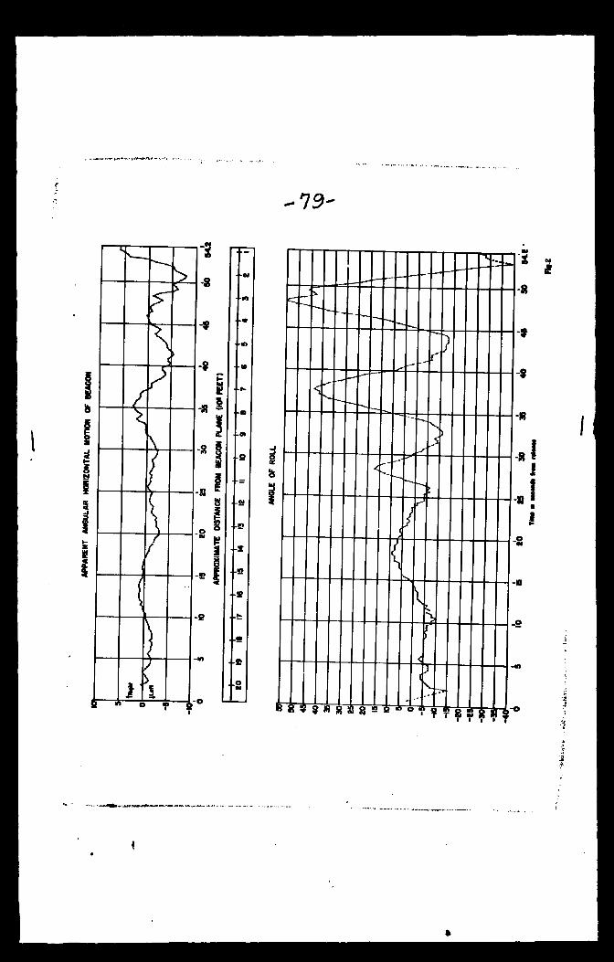
-79-
w-~.
f* )
/ ^
T t [
:
-s
o » B
-9
-s a
! 8 §
+B
+B
+« 4-fc
4-s
+s
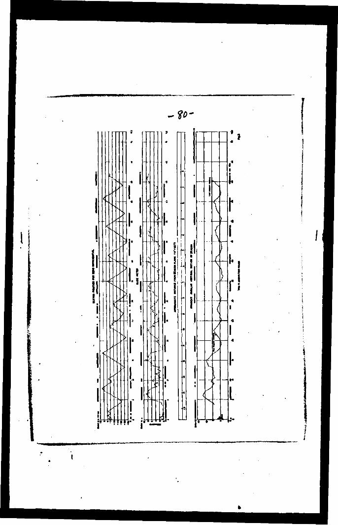
-?0-
II
'x
<,
<
<-'
V- ,'
>
s'
<
"I
,'
p! \
;>_
,'
r
-i
[
:>
••-..
r •* i
s
•<
si
ix-
_-
f
^

II'
s
1

-M-

89-
• ••••»»•••••RHillftaini »•••••»»*• IMIIIIIIHHVIIHUIIUlliMUtlRI MIIUIinHtl|UtUIUltlll»ltUI INHIIHUilHIlilUIHIHfllllllll lk*nillllR>:riliilMIIHI|lllPEllliil • ••••••••••MiiiHlimuduiitQiii HIIIIIIIIUIH>lkllini(lll»IHli.> ••••UMiifaiiiiiimiltiin**6--*!


I CONFIDENTIAL TITLE: Some *^spects of the Design of Homing Aero-Missiles
AUTHOR(S): Dryden, Hugh L. ORIGINATING AGENCY: National Bureau of Standards, Washington, D. C. PUBLISHED BY: (Not published)
ATO-2089 (None)
OHIO- AGENCY NO.
(None) PUBLISHING ABENCY NO.
(None) DATO
(None) DOC. CLASS.
Confd' 1 COUHTBY
V.g. IAMOUAGI
•Eng. •UumATIONS
tables, diagrs, granhs ABSTRACT:
The report pertains to homing devices for. guided missiles. There are five classes of missiles, and they are placed in each class according to source of control. The five classes are listed and their means of control are discussed. Maneuverability of guided missiles and aerodynamic problems pertaining to them are discussed in detail. In con- clusion, the various problems pertaining to launching are given.
DISTRIBUTION: Copies of this report obtainable from Air Documents Division; Attn: MCIDXD DIVISION: Guided Missiles (1) SECTION: Guidance and Control (1)
ATI SHEET NO.: C-l-1-80
SUBJECT HEADINGS: Missiles - Homing guidance - Command (52100); Missiles, Guided - Control systems (32800); Missiles, Guided - Aerodynamics (32350); Missiles, Guided - Con- trollability (32830)
Air Documents Division, Intolligonce Department Air Material Command
AIR TECHNICAL INDEX
CONFIDENTIAL Wright-Patturton Air Force Base
Dayton, Ohio

DEPARTMENT OF DEFENSE
WASHINGTON HEADQUARTERS SERVICES
1 155 DEFENSE PENTAGON
WASHINGTON. DC 20301-1 155
Ml-MORANDUM FOR DEFENSE TECHNICAL INFORMATION CENTER(ATTN: DTIC-OQ INFORMATION SECURITY)
8725 JOHN J. KINGMAN ROAD, STE 0944IT. BEEVIOR, VA 22060-6218
SUBJECT: OSD MDR Cases 12-M-1563 and 12-M-I578
MAR 7 2013
At the request of , we have conducted a Mandatory Declassification
Review of the attached documents under the provisions of Executive Order 13526, section 3.5,
for public release. We have declassified the documents in full. We have attached a copy of our
response to the requester on the attached Compact Disc (CD). If you have any questions, contact
me by e-mail at [email protected], [email protected], or [email protected]
or by phone at 571-372-0483.
Attachment:
CD
Robert Slorer
Chief. Records and Declassification Division

DEPARTMENT OF DEFENSE WASHINGTON HEADQUARTERS SERVICES
1 155 DEFENSE PENTAGON WASHINGTON, DC 20301-1155
Subject: OSD MDR Case 12-M-1563
Dear :
MAR 7 2013
We have reviewed the enclosed document in consultation with the Department of the Air
Force and have declassified it in full. If you have any questions, contact me by e-mail at
[email protected] or by phone at 571-372-0483.
Sincerely,
Robert Storer Chief, Records and Declassification Division
Enclosures: 1. MDR request 2. Document 1


![Design Alternatives and TRIZ PLM World 06.ppt [Read-Only] · Altshuller identified 40 common Inventive Principles used in inventive solutions: The 40 Inventive Principles are used](https://img.pdfslide.us/doc/110x75/5ea23a55b9004e19cc4221b7/design-alternatives-and-triz-plm-world-06ppt-read-only-altshuller-identified.jpg)