Embed Size (px)
Citation preview
UNCLASSIFIED
AD NUMBER
CLASSIFICATION CHANGESTO:FROM:
LIMITATION CHANGESTO:
FROM:
AUTHORITY
THIS PAGE IS UNCLASSIFIED
ADA801141
unclassified
confidential
Approved for public release; distribution isunlimited.
Distribution authorized to DoD only;Administrative/Operational Use; 06 MAR 1947.Other requests shall be referred to NationalAeronautics and Space Administration,Washington, DC. Pre-dates formal DoDdistribution statements. Treat as DoD only.
NASA TR Server website; NASA TR Server website

(,Jopy No. •A
J..
RM No. L6Ja)
, ,.
1. l
j
.'='';~"(. :::-~- .... -"- - ......"'~.~l""'-~~. _....~.
---
~ ;),~r~:f:-;~~:"ir"I'y -,~R.a~-_~~~g",":J.a~r,:: ,,~,~.-~
·o,cRESE*icH MEMORANDUM
'COMPARATIVE DRAG MEASUREMENTS AT TRANSONIC SPEEDS
OF AN NACA 65-006 AIRFOIL AND A SYJl.A:METRICAL
CIRCULAR-ARC AIRFOIL
By
Jim Rogers Thompson and Bernard W. Marschner
,J
Langley Memorial Aeronautical LaboratoryLangley Field, Va.
<:LAMIlPmD IlOClII<ZIl'I'
I, .,
NATIONAL-"ADVISORY COMMITTEEFOR AERONAUTICS
WASHINGTONMarch 6, 1947
':: - -~-

\-I'lACA EM No. L6J30- ~
- - -- - -- --
II!fii11!!flllI~]J~llilJil~lill~lljl- -3 1176014362611 ..
".-- -~---- --_.~---'_.-...._-~
NATIONAL A!NJ13~: COMMJ...I"l'EE FOR AEROID1QTICS
COMPA.lUI.TIVE IIaAGl~ AT TBA:NSOm:O SPEE'£6.. . - . .
" OF'~ :NAeA: 65:"006 :AIBFo1L AND 'A ~C.AL -~ .,. .. . , .
" '
_omCULAR~ARC -AIRFOrr.
:By J1Jn. Rogeis ThallpsOn a:nd. :Bernm-d 'W. Marschner
- I
:; .... Mea,surem.ents hB.ve: been :made, at transonic speecle by the,freely-fail1ng-body method. to campare the drag of a rectanguJ.arplan-f'orm airfoil of aspee;t ratio 1. 6 havi:ng an NACA 65-006 sectionwith that of an airfoil of 1deIIticaJ.. plen fo:on and maximum. thicknesshaving a' s,ylli1Iletr.icaJ.: circular-arc section. These. measurements,which 'were'~ to .deter.m1ne opt1m.um. aorodyDamic ehapes andconfigurations for use in the transonic- and. supersoni.c-speedraIJges l ' shoW:ed- the drag for the eymm.etricaJ. 6-percent-thick - .cil'cuJ.ar-erc airfoil to be 16 percent greater at the speed ofsound. and:'ll percent gr~e;~er at a Mach number of' ~~~6than thedrag of. the 'NACA 65-006 airfoil. In an. effort to simplify thotest :PT0cedure,both airfoils were mounted on the aeme body, thecU'cuJ.e.r-arc airfoil to the rear, of and at right w..gJ.os to theNACA 6~-oo6' aii:-foU. As t1le- ef'fect of' this silllpJ.ification mtWbe assumed: to be J.':tmited to the iriterf'erenco ef'f'ect noted ,in
':'Previoua tests(i~ w~ch the mee.sureq. drag of en o.irfoU in the. front pQsitiQn was fU'ightly gr.eater than the measured drag for
an. identical' airfoil in the roar position) J it~ be concluded-that the actuaJ. drag dU'f'erence is greater thon that mecsured.The most probab~e value of the drag of the circular-arc airfoilis about 20 to 25 percent greater at a Mach numb€lr o:f 1.0 and~5 t.o ~9 percent greater at a :Ma.ch number of ~.J.6 then the dragof the NACA 65-006 airfoil.
Oomparison'tvith the resuJ.ts Of' previous tests of an NACA 65-009a1rfoi~ shoWed the drag per· unit of' :rrontai moea for this airfoi~to be a~out L7 po3:'ce,nt gJ;'eater at superso:n.ic S]?Ooda iih£.n tho -dragof t11e NACA: 65-P06 airfoU.
• a
J
,Df1'RODUCTION
NACA EM No. L6J30
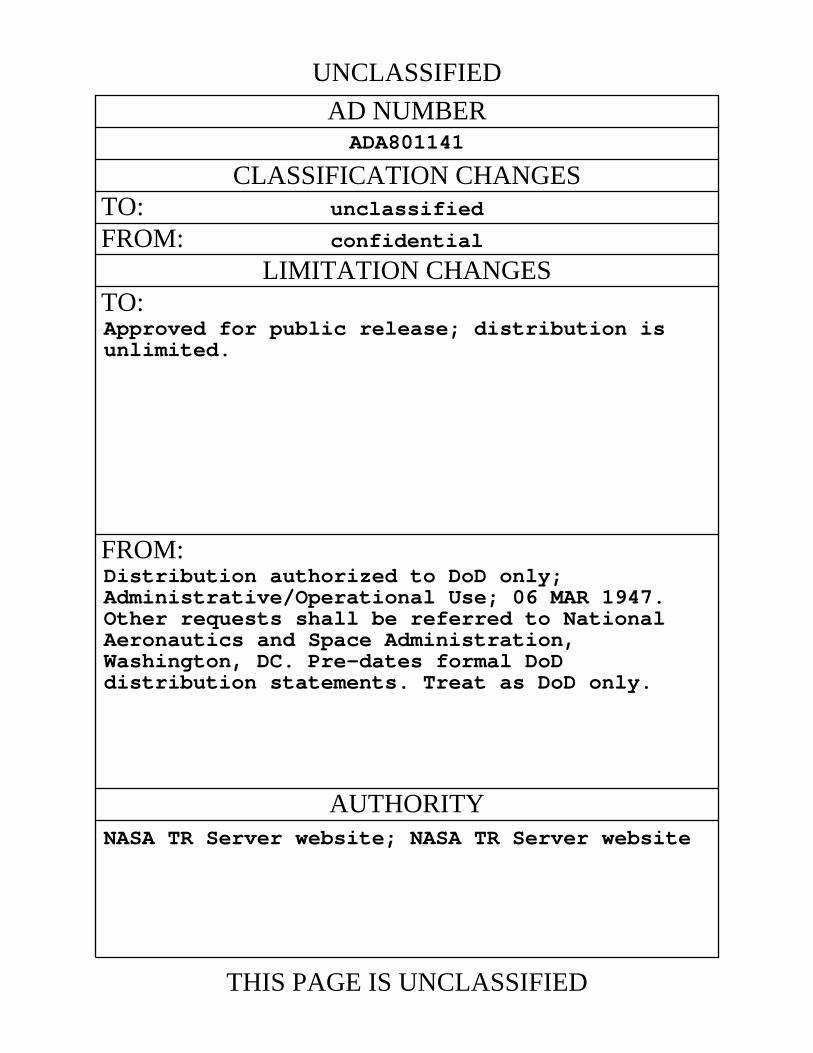
One of' the ma.ny problems encountered in the design ofa1rcraf't for the transonic and the supersonic speed re.nses isthe selection of an airfoil Bection having low drag in thedesign h1gb-speed range yet having good. low-epeed characteristics,especially a high ma"J1nmm lift so tha:t a safe landing speed maybe obtaimd.• Several of the proposed designs for such aircrafthaVE) incorporated sharp-nose airfoils of the biconvex or doublewedge type; these airfoils, although having lesa desirable lowspeed characteristics, are assumed to have lower dra.gs at supersonio speeds thaiJ. conventional rounded-nose airfoils. Theassumption that sharp-nose airfoils have lower drag at euperaonicspeeds ia supported by the literature (roferences l. to 31 althoughexperimental. evidence oonfirming this assumption is practicallynone:ti6"tsnt •
As part of the researoh program of the National AdvisoryCommittee for Ae:ronautics to determine airfoil sections, wingplan.forma, body s~pea, and winged body ccm:f'1g".n'ationa haVinga mininr.11Il. of drag in the transonic and supersonic speed rangea,tests Lave been made b7 ~he Flight Bes3arch Division of thaLangley Memorial Aeronautical Labore:bory to compare the dragof s~-nolJe and conven:t:.tonal low~ag airfoil sections attransonic speeds. T".o.e resu1ta of these tests are presentedin too present paper as a comparison of curves ahawinS themeasured variations of drag coeff'icient with Mach number fora reotang.u.ar plan-form wing having an NACA 65-006 section andfor a wing of' identical plan fOl"III. having a synJnetrical circular-e.roaectirm of' the 'sema ma:.dmum thicknssa. The tests ware performedby means of' the f'ree1y-fa.J.ling-body method described in reforences 4to 6.
APPARATtB .AND MErHOD
. Teet bo1.y and airfoils.- Tho general arrangement of the teatconfiguration ia ehOW!l by 'the photograph (fig. 1) and the detailaend. di:.l:B9nsiona are shown on the line drawing (fig. 2). The twotest. airfoils had. identical rectangular plan f'orms and frontalareas and. differed only 1n airfoil section; the front airfoilhad NAeA 65-006 sections and the rear airfoil had symmetricalcireular-e.ro seotions With a maximum thickneee of 6-percent chord.The teet airfoils were oonstructed of' metal, and. because of' themachining techniques used the l.eading and trailing edaes of' the

3
,
NACA EM No. Lbr30
circuJ.er-erc airfoil were somewhat flattened. Ths oontour of theseedges m~ be approx1mated with a row mum d:tacrepeDCY' of 0.001 inchby a. radius of 0.005 inchl or about one-fourth of the J.eading-edseradius of the NACA 65-006 section. The teat e.1rfoUs (includingthat part of the airfoil wi"thin the body) had an aspect ratio
of 7.6 and entered the body through rectanguJ.er slota ~ inches
l.ong and. 1 inch wi~. The body on which the teat airfoils 'Weremounted was the same as the body used in the teste of J.·eferences 5and 6 with the exception of the tail faiJ:"iIls. The sm.all fe1r1..'I1Bused. previously vas repJ.aced for the pi.·esent test by a cyJ.indriceJ.extension \nth a fiat base so that the preasUt'e acti:ng on such aflat base couJ.d be measured.-
M~'§§m:'...£m€!~ta.- Heasw::ement of the desired quantities wasaccan.plished as i.1J. the p.--:OBvious tests (references 5 and 6) throughuse of the NACA re.d.io-telemetering system end radar end. phototheodolite equipment. The following quantities were ;l.·Elcordedat two separate ground stations by the ·teJ.emsteriDg system:
(1) Force exerted on -~ by: each test a.:1rf'oU as measuredby a spring balance .
(2) Total. retardation of body and airfoiJ.e as measured bya sens:itive accelerometer aJ..ined with longitudinal ex1s of body
(3) Pressure acting on nat base of test bod3" as measuredby four orifices conneotied, to an aneroid cell.
A t:tm.e history of the :position with respect iio gt'ound. axesof the body during £'ree faD. was recorded by rader and photothecdollte equipn.ent, and a survey of' atmospheric conditioneapplying to the test was obtained from synchronized records ofat-moB1?he:t'ic prcssure l temperaturo l and. geanetric aJ.titude takenduring the descent of' the e.1rp~ene from wh1ch the test body wasdropped. The direction and velocity of' the hcri.zoniiaJ. componentof' the wind in the range of' aJ.titude for which deta are presented.were obta:1ned fran. redar and. photctheodolite records of the- pathof the aecensdon of e. free baJ.J.oon.
Reduct;!.on of' data. - As in the provious tests iihe veJ.ocity nthrospect to ground axes V of' the body durinG £'ree falJ. woa cbtainedboth by differentiation o~ the flight path detel"Illined by ra.d.a.r endphototheodollte equi!fll6nt end by integration of the vector sumsof gl:'avitioneJ. acceleration and the directed retardation measuredby the 10ngitudinaJ. acceJ.eromoter. ~El true airspoed V was
••••

4 NACA EM No. L6J30
obtained. by veotoriall;r adding the velooity VS and. thehorizontaJ. ~rind. velo~ity measured at the appropriate altitude.
The drag D of each airfoil was obta.1Iled frc:an the relation
where
R measured. reaction between airfoU and body1 pounds
WT weight of airf'oU assembly supported on spring balances,pound.s
fie rea.d.1rig of acoGJ.eraneter (retardErtion), g
The atmospherio pressure p, the temperature T, and theairfoil fronteJ. area F were ocmbined witb a1muJ.taneoUB val-ussof true airspeed and airfoll drag to obtain Mach number M andthe ratio DlFp. The variation or the parameter DjFp withMach number affords a simpJ.e and oonvenieIIt means for expressingdrae in the transonic-speed. re:nge as a :f'unotion of Mach number laltitude, and size.
Values of oonventional drag coeffioient 1la.ae~ on frontal ar-oaOnE wcre obtained from the reJ.ation ..
D/FpODE ==-
'l..JR.2
where the ratio of speoifio heate r was taken as 1.4. nt'88ooefficients based on pJ.an area On were obtained. by multipJ.yiDgthe values of Cn:F by the ratio of frontoJ. area. to plan area.
ArGas used. did not include that area enclosed 'Within the body.
RESULTS
A time history of important quantities obtai.nod in the presenttest is :Prescnted. as figure 3.
Velocity meaaureme~.-For purposes of' comparison the groundspeed V S obtained:rrom each of' the two independent methods of-_&

NAOA EM No. L6T.30 -----."" 5
measurement is presented in figure 3. The ground-sIleed. data obtainedfrom. the acce'Lez-cmetier- are shown as a soJid. J.:ir'..e, and the rader end.phototheodoli'te data,~ re:groaen'ted by t.os:f:; points. From thie: :figurethe m.a.x1m.um. discrepancy in Vg can be seen to be about 13, miles perhour aJ.though tho mean discre:gancy is considerably srnal.l.er. Asno ayste:me.tic discrepancy of the tYIle norIll£l.1.J.;r associated withaccelerometer errors (a gradual diverging of the curves) is lI.Ilparentano., as careful study of the records disclosed. au intermittentfluctuation of as much as J. percent in the rate of the clockused. to ·provide a time bese for the radar and phototheod.olitorecords, the accelerometer data are considc·red to bo tho mornreliable. The ro.dE.r end phototheodol1tc dn.ta ]rosented. have 'beoncoz-r-ectied for the avorS,Je -:'iming error; hawevor" individ.ual pointsor groups OI~ points'may be in orror by as much as 1 po:kont of thevelocity because of the intermittent nature of the rate fluctuo.tionThe velocity data obtc.inod. from the accelerometer, convcrtod to truoairspeod V by:u.sc, of the win..'i data, arc shawn :i~ the timo historyas a dash-line fairine. This velocity was uaod, to ccn:n;pute thoM..'l.i~h numner-, which is believed to be accurate -w.I:thiR to.oa. The'Mach n'LlI:lber corrospon.ding to the ground. speed. V is also shownin figuro 3 so that tho mngn1tude of the wind c~ec-::'ionme;rbe readily seen,
;Base-presslIt"e meaeur-emerrba, - The measm'e!l!ent of base pressurewas obtained. incidontally to the subject test for uae in body-aragresearch. Although analysis of these data is beyond tho scopeof the present paper, these measurements &:-6 included so that aminimum. of d.eJ.~ would. be incurred in makitlg the informationgenerally available. The equipment used to measure the basepressure required that this pressure be known at same point d.uringthe test. This reference pressure was caJ..o.ulatE"-d i'or a point1mnediatel..Y following the release of the tost bod"v by use ofthe results of reference 7. Results from. reference 7, whichreports wind.-tunnel meaaua-emerrcs of the pressure acting on atote.1.-:gressure tube at an engle of ye:w of 1800 a.t Mach numbersfrom. 0.3 to 0.9, are shown in figure 4. whore the retio of' basepressure to atmospheric pressure ia plotted against Mach number.The froe-faJ.J. data, which are aJ..so plotted in f'igure 4. are seento agree closely with the wind-tunnel data fram. M: = 0.611- wherethe f'ree-f.'a.lJ. data were referenced? to the ma;x1 mum .Mach mmibernttained. in the tunnel tests (M =0.9).
Airfoil drag measurementa. - The spring be.l.ances with which theairfoil arag forces ere measured must w1thstand the high drag forcesoocur:dng at suporsomc Mach numbers and. hish pressures (low altitudes)and are thereforo necessarily relatively insene;ttiyo to the s:mclJ.drag occurring at eubeontc Mach numbers and ~ow pressures
• •
NACA RM No. L6J'30
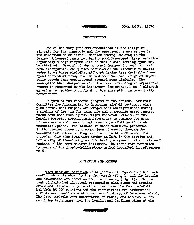
(high tUtitudes). The drag parameters are therefore less accurate atthe 10'"...~st Mach numbers t'or which data are presented than in thesUll>3rsonic range vhere the drag is high. The values of the ratioDfFp a...'r'G believed to be accurate within abottt ±O.Ol at M. = 0.85,the linrl:t of accuracy decreasing to ±o.oo4 at M ::& 1.16. Corresponding values of' CD are accurate within ±.O.OO13 at M = 0.85and withi::l. ±ooQ.')o6 at M =1.16. These values correspond toabout 1 percent of the t'ull..:..scale balance deflection for valuesof D/Fp; however" the values of On include an additionalinorement due to the possible uncertainty in Mach number of ±o .Ol.For these reasons" the range of the balance should be chosen asama.:u as possible so that results of usable accuracy can beobtained near the drag rise. For th19 tests herein reported,the range was chosen oJ.'.shtly too emall with the result that noairfoil drag da~A. were o·~ta1ned for the le:::tt 5 seoonda of the drop.(See fig. 3.) As the :r.13;~e of change of Hp....ch n"JDl1>er ,nth timeis small near tile end of the drop, however" data for only 0.02of a Mach numjer were lost. The Reynolds ~9r, baaed on thea1rfOi~ chord, inoreased from about 0.75 x 10 at release to5 x 10 at M=1 016.
TOO results of the airfoil drag measurements are summarizedin figure 5 wIl3!'e curves e.l'l3 presented which show the meaallt"edvariat10:c.a of D/Fp, Cnp., and CD with Mach number for both
the NACA 65-006 end the symmetrical c1rcul~ airfoils. The
ip- curvea of figure 5 show that for the NACA 65-006 airfoil
the drag per tmit of frontal area rose abruptly from. about 0.05of atmospherio pressure at M =0.88 to 0.36 of atmosphericIU'easure at M = 0.98. The drag per unit of frontal area thenincreased almost linearly to 0.51 of atmosj;lheric pressure atM :110 1.16. For the &ymmetrical circula.r-e.rc a1r:f'oil, hovever,the drag per unit at frontal aree rose at first lass ab!'1,tptlyand then moro abruptly than the drag of the llACA 65-006 airfoil, tbedrag increasing from. 0.07 of atmospheric pressure at M =0.88 to0.42 at M= 0.98. The drag of the circular-e.rc airfoil then increasedat about the same rate as the drag of the ?lACA 65-006 airfoil andreached a vaJ.ue of d...1"8g per unit of frontal area of 0.57 of atmosphericpressure 0:'';; M = 1.16. '!1le drag of both airfoils began to rise abruptlyat about M = OaOO; however, the circul.aJ."-e.rc airfoil had a greater dragthan the NACA 65-006 airfoil at the lower Mach numbers by an amountapproximately equal to the accuracy of the measurament in thl1s region.
DISCUSSION
For purposes of comparison, ip-etn'Ves for the airfoils, tests
of which are presented herein, and ~or an NACA 16-006 airfoil of

7
aB:pect ratio ~.9 mourrbed, on aDdif'f'erent type of body (ref'erence l~}are shown in figure 6. The Fp-curves f'or the NACA 65-006 section
and for the NACA ~6-006 section agree) c~osely; this resuJ.t wasexpected because of' the aimi~ar1ty of the p-rof'i:Les but prov1desconfirmation for the measUl~ement. Further conf'irmation ia:PJ:'ovided. by' as yet unpublished. results ·:from free-faJ.J. tests ofliACA 16-006 airf'oi:Le mounted. in the same mamJ.er as the e.:1r:f'oUsof reference ~ on a body of' considerably higher fineIl.e8S ratio.
Previous tests of identical rectangv~ar plan-f'ar.m a1rfo~s
tested in both the :front and rear :positions on the body (references 5and 6) showed. that at sl.lperSOIJ,ic s];leeds a higher drag. wasmeasured for the front airfoil than for the rear airfoil. Thisdiff'erence, which amounted to 0.02 to O.O~ nt. YeJ.t1.e.~. of n/Fp of0.4 to 0.6, was J;lres'I.lm9.bly due to the location of' the airf'oiJ.s indifferent :pB...'>"ts· of the flow f'ield. of the body end./or the effect ofthe front a1rf'oi~ on the rear airfoil. .Curves ot D/E-p f'roml.'e~erence E. are p-resented. in figure 6 to illustrate the Illagni:tudeof the resulting interference effect. .
DCc:anparison of the Fp-curves of figure 6 shows that the drag
of the airi'o1l having the symmetrical circular"arc section wasgreeter than tl].e drag of the· ~f'oil having the mCA 65-006 sectionthroughout the tested. Mach number range, the Illaas1.U"sd tll.fferenceamounting to 0.06 (l6 percent) of atmospheric pressure :Per tmitof' frontal ares. at 14 = l.. Th1s diff'erence was constant fromM = l. to M = l.l6; hmrever, ai; M = ~.~6,. the dii"f'erence haddecreasod to II percent•.. If the interference effect noted inIlrevious tests can be assumed. 'to a:ppJ.y to the present test inwh1ch airf01ls of different se:ction are mounted. on the same body(the NACA 65-006 section in the front pos1tion),. the actual.difference between the drags of the circular-arc and. theNACA 65-sor16e sections 1s 8Cl1J16what greater the:t that measured.The most :Prvbab~e vaJ.ue of the drag of the circul.~-arc sectionis thero:fore 20 to 25 J?6rcent gre6.ter at . M = ~ and ~5 to 19 :percentgroatElJ:' at M = J..16 than the va1.ue of the drag o~ the NACA 65-006eectn.on.
Tosts of rectangular plan-form. airfoils of' aspect ratio 2. 7having N.l\CA E5~009 and. 9-perceIIt-thick circular-ere sections havebeen re];lortod.. in roforence 8. Those teet a.1rfolls 'W6re attachedto a rocket-propelled. body similiar in shape to the body used inthe free-fall tests. The NACA E5-009 airf'o1l was found. to haveLeas dreg at M = 1. than the circuJ.ar-arc airfoil. by about theSI3JIl.6 per-conbage shown by the free-faJ.J. data; howover" at aMach numbc.r of a.as the difference had decr-eased to only 5 J?6J.'cent.

8 NACA IlM No. L6J:10
Comparison of' tho ~-curve8 shown iIi fiBUJ:"e 6 for the
NACA 65-006 airfoil and the NACA 65-009 airfoil (reproduced fromreference 6) o£ identical plan far.m and' aspect ratio testedin the same position on the body (thus eliminating the differencein interference effects) shows that the 9-percent-thick 65-seriesairfoil had about l7 percent more dxag per unit of' frontal area. at,supersonic speeds. A sim11ar comparison indicates that the6-percent-thick circu.J.8.1'-arc section had a. drag per unit of:f:rontaJ. area. slightly greater near M = 1 and about equal atM = 1.16 to the drag of the NACA 65-009 section preViously tested.
The drag results obtained for the aym:netricaJ. c1rc1l1ar~arc
section ere not ca1lp8J:ed with the Ackeret theo!';}- as the datado not extend to'Mach numbers high enough for the theory to beapplicable- According to ceJ.cuJ.atibn, an obli:we shock wavewouJ.Cl. not attach to the lsadi.og edge of the airfoil (the condit10nfor application of the Ackcret theOry) until a Uach number of'1·32 was attained.
The lower drag herein reported for the conventionaJ.. roundednose airfoil section at low'Buporsonic speeds and the completeinadaquacy of present theory to predict the characteristics ofth1s type of section even in the higher mt:ilGTson1c-spced range,where reasonably adequate theory is available for sharp-nosesections, shows the necessity for further tests at higher speeds.These tests should determine the extent of the lovrer drag for therounded-nose airfoil section into the supersonic-speed r-ange and,at speeds above this range, whether the magnitude of' the possibledecrease in draa caopensates far the leas desirable low-speedchara.cte:ristics of the sharp-nose airfoil sections. Theresearch should be directed toward determining the optimumairfoil 'for eny design Cond.1tion and therefore should :l,ncludeconsideration of control effoctiveness and lift characteristics-
. CONCLUDmG REMARKS
Drag measurements have been made at tro.nsonic speeds bythe frae~v-fallins-bodymethod for rectangular plan-for.m airfoilshaVing en aspect ratio of 7-L and having NACA 65-006 andsymmetrical 6-percent-thick Cil"culer-arc aectLona- 2.'he rooultsshow that tho drag per u:oit of frontal area f'or th(;) NACA 65-006
.r.J:d'oU rose abruptly from. 0.05 of' atmospheric prossure at aMach ntmlber of' 0.88 to 0.36 at 0. Mach number of 0.98 and then1ncrensed almost linearly to 0.51 at a ~~h number of 1.16.The: drag of the airfoil ha~1rig a eymmetrical circular-arc section
m

,
NACA BM No. LtJ30
wa.a greater than the drag of -che airfoU having the NACA 65-006section throughout the tested Mach number ra:nge1 -che meas1.lreddifference amounting to 0.06 (~6 perceIIb) of a:tmoapheric pressureper unit of f'ronteJ. area at a Maoh number of~. The differencewas constant from a Mach number of ~ to a Mach 1'lUI:!loor of ~. ~6;
however, at a Mach number of ~.~6 the difference had decreasedto II pezcenb , If the interf"erence effect noted in previous"bests in which identical. airfoils were tested in front and. rearpositions on the body can be assumed to apply to the presenttest in which different airfoils ere molmted in the two positions,the most probable vaJ.ue of the drag of the circular-arc o.i:rfoUis about 20 to 25 percent greater at a Mach number of' L ?Dd 15to J.9 percent greater at a Mach number of' ~.~6 than the drag ofthe NACA 65-006 airfoil.
Oomparison of' the NACA 65-006 airfoil with an NAOA 65-009airf'oi~ previously tested. in the same position on a similar body(thus eliminating the difference in bodJr-interference effects)showed that the 9-percent-thick airfoiJ. had about ~7 percent moredrag per unit of' :frontal. area at superson:i.c speeds.
9
Further tests a.t higher SllcodB shoul.d, be :performed to determinethe extent of the ~ower drag of the rounded-nose airfoil soction,herein rellorted. for the transonic end low superson:1c-s:peed ranges,into the higher supersonic-spoed range. At sIlOed.e at which therounded.-nose sec"bion has higher drag these tests should determinewhether the :magnitude of the possib~e decrease in drag compensatesfor the ~ess desirable low-speed characteristics of the sharp-nosesections.
Le.ngley MemoriaJ. AeronauticeJ. LaboratoryNational Advisory Committee for Aeronautics
Langley Fie~d, v».
r
10 BACA RM No. L6J3o
1. B~ma.nn" A., end Walehner" 0.: Prof'Ueigensoha:f'ten be1. UberscheJ.lgeschwiDdigke1t. Forech. auf dem Gab. des
Ingenieurv., Ausg. A, sa, 4, Hen 2" March/April 1933,pp. 87-92.
2. 14ShthUl, M. 3.: Two-D1mens1cmal Supereon1c AerofoU Theory•.R.&: M. 1"0.1929" Br1t1shA.R.C., 1944.
3. Evald,. P. P." l'5sohl" Th., and. Prandtl" L.: The Physics of. Sollds and Fluids. Seoond ed." :Blaok1e & Son, Ltd.
(London and Gla.sgov), 1936"oh. vrr, p. 383.
4. Batley" F. J." Jr." Mathews" Charles W." and. Thompson" JimRogers: Drag Mea.surement s at Transonie Speeds on a Freel,.Fa.llJ'ng Body. NACA ACR No, L5E03, 1945.
,. Mathews, Charles 'WI' and Thompson, Jim Rogers: ComparativeDrag Measurements a't Transonic Speeds of' Rec'ta.nsuJ.a,r end
" Swept-Back NACA 651-009 Airfoils Mounted on e. Freely FallingBody. MeA ACB Ho. L5G30, 1945.
6. Matbmrs, Charlos W., and Thompson" Jim Roge1"B: DragMaasUreIOOnts at Transonio Speeds at NACA 65-009 A1rf'ollsMounted on a Freely Falling Body to Determine the Effeots
. of' Sweepbaok and ~ct BatI0. NACA EM No. L6Ko8o, 194.7.
1. Humphreys, Milton D.: Et:foots of Compressibility and LargeAngles of Yaw on Pressure Ind10ated by a. Total-Pressure'rubo. HA.CA RB Ho. L5C30" 194-5.
8. AJ.exander" Sidney R.: Drag Measurements or SymmetrioalC1rcu1a%'-Aro and NACA 65-009 Rectangul.e.r A1rf'olls Hav1nsan Aspec't Ra.tio of 2.7 As Determined by F1ISb,t Teetsat SUllOrsonio Speeds. NACA RU No. L6Jl4, 1946.

NACA RM No. L6J30
~---....
-"..
- \
Fig. 1
Figure 1. - Side view of the airfoil test body.

7U~
l-40~,~rr Ii'ECTANGtILAfl '''RFtXL
If)(;lfrlON
rA
I »>:~
- -ES - -l
1~
r 1r----:JO ~s J ~II- 25-
.....It -
AIWOIL - SECTION COOIfDlNATt:5(NACA 6S-OO' .5ECT/ON)
X If X 'I X 'I.000 .000 1.600 .1" 5.2()O .180
R) .oea .O,M sooa .216 5:600 .1.55.000O .~ esca ,2i!fJ '"000 .126.100 .05'f e.8(X) .2!16 ~400 ,099.200 .or, 3.200 .e-IO 6.800 .069
.400 ,f05 3.600 .239 r.DO .lJ.1.1,600 .127 "1iXXJ .J1!12 7,1iOO ,016.800 ,1-16 ~.IfOO .219 (1,000 .000
UGO ./7' ".,800 .~ .._--- .... - ......""''"'*''''- ~SOllY i:«: RAtJll/S: 0.019HAC4 (;5-{)()€ IIIRfOIL (FRCWT)
•• ClIIIIlITm 101 AQClIWITI($
~-==r=:k~-33.~
6-PERCENr-TNICt{ SYMMETRICAL C/RC{/fjlR'"AJK: AIRFOIL (REA
Figure 2.- General arrangement and dimensions of the airfoil testbody. All dimensions are in inches.
::JlJll.

Fig. 3 NACA RM No. L6J30
300-e..
4
4()X
1';>0.--I--~ 1121/ ~ rCh.
A/hfude/-q /
1-8
~~. 17 24
I .:vl
~. 1/ /I
/
i%IG
/1
1/ \Ie
Atmospheric pressure" ,//
-, ~,// C 8
/'...- ~/ 4r-. //
~se pressure ~L--
I--"~I..- 0-1--"- _ - I-- I-
5('
5.~' ./
\l
V I---~ umpen:tture",
J"'" ~ ...- ..... -~ -, l.-----"l.-----" ~
.h - ~ ~- ~ J'''''"''''
A/V1 .900
~ ~33Y' T
.rc: 1
ft IJ" ---r 800Ground speed from radar and pholotheoclo/de datI" '\'"R .>I r 1 I-'"
I I I P ;/ 700
Tr,ue t.1rspe~d<, ~ /..."." 600,~~~
I I ,I l-. ,~
Afacn num7;er
...c-from grou::fdpeed 1/
8tX _Ground spl!1ed from -from airs. -Q?acceleromeier dota
.~~ bY Vr-, 1-- ...../~ -:,. ". 400
V / II,CII'~ ular arc
40(J La-- '-.-c L--- V OIrfoll treat)I.,~
~ V 1UTofal drag -:L'COr-,
~V ~~ iH%A 65-00601 'OI/(front)
o·8 -.;/
2200
800
BOO
6CJO
12
NATICltW. AGYlSOA."I'
Trme after release. sec COIUl/1Tt1IOlAllOlWlTICS
Figure 3. - Time history of important quantities obtained during thefree fall of test body.
....:1 ........

"....
t-- ...... ~...... -- .... -. ...................
I, ....l"- "
~,"-
r----...,""'-...
\• <,-- Reference T
- -,
-- Present rests:<,
r-;
.-.... 'ATIONAL ~DVISORY
COMMlnu FDA AEROIIIAUTIC;S
/.00
.96
~1 Q.
~I., .9?:I
~~IV
~ ~~
\J .88~ i::
~
\l 1~ .84~1-
".80
.76.3 .4 .6 .6 .7 .8
Maen' number, 111/,0 /./
~.
Figure 4.- The variation w10th Mach number of the ratio of the pressure' measured on the fiatbase of the airfoil test body to atmosPherio pressure. Data from referenoe 7 is Shown for .~
comparison. 6Q

Fig. 5 NACA RM No. L6J30
-_ ..... #
--~-.
a
---- AlACA 65-006 fJ/iroti sectIon (rront)--Clrctl/ar-arc O/irOti sect/on (r-ear)
.04 1---I--+--I---+--4----II---4--4----!-r---.l--+_---1
02 1--+--t---1f---+~:4----!--+-+--+--1--+---l
.8
Jl-s,... , .6~ ~~ c::: ,,-i:J ~~-E'i--:\l 8 11::1 'tl~]~
<::l--.:::... .2
o
/.3/.2.9 /0 1/
,Mach numbe0A1.8
o.7
.4 1--1--+--+--+--+-r~.J.-.,._..:I~-+--+-+--+___1
.6
Figure 5.- The measured variati04 with liaoh number of drag coefficients and D/rp forNACA 65-00& and symetriOal ciroular-aro airfoils of aspeot ratio 7.b.

.8
". • ,'1
A/ACA 05-009 a/r/o! (rerere/rce ,)1-----1---4-- --1---1
Front Rear
~~:....n7+---+--¥~CA 16-00' CllrTo/!(reference 4)
I----+--+-----+--~--+---t--___t-/vACA ~5-006 1-----1
aIrfoIl (front)O'-----J,---i.-_-I--_..L----l-.:.;,;,...;..-I",_.....l-_........._I-----Io_......\---..I
.7
Figure 6.- Comparison of results with those of previous tests.

llfVISlONRM-L6130
a - .2 -~ - ~7 It::I'iITla TI0710010, AGENCY NUMllElI
(cCf.\1[lI@Jaf.\1VgA~
DIVISION. Aer~ce (2)SECTION. Wings and Airfoils (6)CROSS REFERENCES. Airfoils - A..rod1MJn1cs (07710);
Airfoile - Deeign (08070);AUTH01US) Airfoila - Dr .... (08200)
15lIID RJI1ICJ BII» F>:l qJ)ThClllpson, J. R.Marschner, B. W,
AMERo TITlE, Comparativa drag lIl8aaur ement .. at transonic speeds of an IiACA 65-006 airfoil anda armmetric~ circular arc airfoil
FO!lG'N. TITlE.
OIlIGINATING AGENCY. NatianA1 Advi eor,. C(Jl:IIittee for Aeronautic.. , IIalIhington, D, C,TllANSlATION,
COUNTRY I LANGUAGE VORG'N.ClAS~ U, S.cLAS5.1 DATE I 'AGES I/UUS'I fEAruaEsU.S. Ens. I I Confd'l IMar'la71 16 I 6 photo, Bl""phB, drvll
A~Yl2ACV
Tests v..r e 1ll'Jd.. to det ermine optilllW!l aerodInamic ehapes and configw-atians far use intransonic and su personic spe lld.B. .The,. ehoved drag for "1!=!'8trical $ th1ck circular-arca1rfoil to be 1$ greater a t e on1c speed and ll~ greate r at Mach n\lllll)e r 1,16 than HACA a i r foil dr!>g, Comparison vith r esults of pr evioue t ..sts ..howed drag per unit of fl-ont areaf or NACA 65-009 airfoil to be about 171> gr ea t ..r at ..upe rsc::nic ep eeds than drag of IiACA65-006 airfoil .
walGHT FIELD. OHIO. USAAFtn-o-21 ~ #t1 110
RC1I'E : Requ..ste f or "opies of this r eport must be addre ssed to:lIa..hington , D. C.
T-2, HQ. AIR "'"TERIEl COMMAND
R.A.C.A.,