Embed Size (px)
DESCRIPTION
OPERATOR'S MANUAL FOR THE MCU-2 SERIES GAS MASK
Citation preview
T.O. 14P4-15-1TECHNICAL MANUAL
OPERATION AND MAINTENANCE INSTRUCTIONS WITHILLUSTRATED PARTS BREAKDOWNCHEMICAL-BIOLOGICAL MASK TYPE
MCU-2A/PMCU-2/P
PART NUMBERSMINE SAFETY APPLIANCES
MCU-2A/PMCU-2/P
88115010-10 MCU-2A/P SHORT88115010-11 MCU-2A/P MEDIUM
88115010-12 MCU-2A/P LONG88115001-10 MCU-2/P SHORT (KIT)88115001-11 MCU-2/P MEDIUM (KIT)
88115001-12 MCU-2/P LONG (KIT)(ATOS)
This publication supersedes T.O. 14P4-15-1 dated 30 June 2000, change 3 dated 5 August 2002.
DISTRIBUTION STATEMENT: Distribution authorized to US Government agencies and private individuals or enterprises eligible to obtainexport-controlled technical data in accordance with regulations implementing 10 U.S.C. 140c (12 May 2003). Controlling DoD Office is WR-ALC/LKC, Robins AFB GA 31098. Questions concerning technical content should be directed to WR-ALC/LESGF.
WARNING: This document contains technical data whose export is restricted by the Arms Export Control Act (Title 22, U.S.C., Sec 2751 etseq.) or the Export Administration Act of 1979, as amended (Title 50, U.S.C., App. 2401 et seq.). Violations of these export laws are subject tosevere criminal penalties. Disseminate in accordance with provisions of DoD Directive 5230.25.
HANDLING AND DESTRUCTION NOTICE: Comply with distribution statement and destroy by any method that will prevent disclosure of thecontents or reconstruction of the document.
Published under authority of the Secretary of the Air Force
12 MAY 2003
T.O. 14P4-15-1
INSERT LATEST CHANGED PAGES. DESTROY SUPERSEDED PAGES.
LIST OF EFFECTIVE PAGESNOTE: The portion of the text affected by the changes is indicated by a vertical line in the outer
margins of the page. Changes to illustrations are indicated by miniature pointing hands.Changes to wiring diagrams are indicated by shaded areas.
Dates of issue for original and changed pages are:
Original . . . . . . . . . . . . . . . . . . . 0 . . . . . . . . . . . . . . 12 May 2003
TOTAL NUMBER OF PAGES IN THIS MANUAL IS 76, CONSISTING OF THE FOLLOWING:
Page *Change Page *Change Page *ChangeNo. No. No. No. No. No.
Title . . . . . . . . . . . . . . . . . . . . . . . . . 0A . . . . . . . . . . . . . . . . . . . . . . . . . . . . 0i - iii . . . . . . . . . . . . . . . . . . . . . . . . . 0iv Blank . . . . . . . . . . . . . . . . . . . . . . 0v - vi . . . . . . . . . . . . . . . . . . . . . . . . 01-1 - 1-4 . . . . . . . . . . . . . . . . . . . . . 02-1 . . . . . . . . . . . . . . . . . . . . . . . . . . . 02-2 Blank . . . . . . . . . . . . . . . . . . . . 03-1 - 3-8 . . . . . . . . . . . . . . . . . . . . . 04-1 - 4-11 . . . . . . . . . . . . . . . . . . . . 04-12 Blank . . . . . . . . . . . . . . . . . . . 05-1 - 5-23 . . . . . . . . . . . . . . . . . . . . 05-24 Blank . . . . . . . . . . . . . . . . . . . 06-1 - 6-7 . . . . . . . . . . . . . . . . . . . . . 06-8 Blank . . . . . . . . . . . . . . . . . . . . 0A-1 - A-2 . . . . . . . . . . . . . . . . . . . . 0B-1 - B-4 . . . . . . . . . . . . . . . . . . . . . 0C-1 - C-2 . . . . . . . . . . . . . . . . . . . . . 0D-1 . . . . . . . . . . . . . . . . . . . . . . . . . . 0D-2 Blank . . . . . . . . . . . . . . . . . . . . 0
*Zero in this column indicates an original page
A USAF
T.O. 14P4-15-1
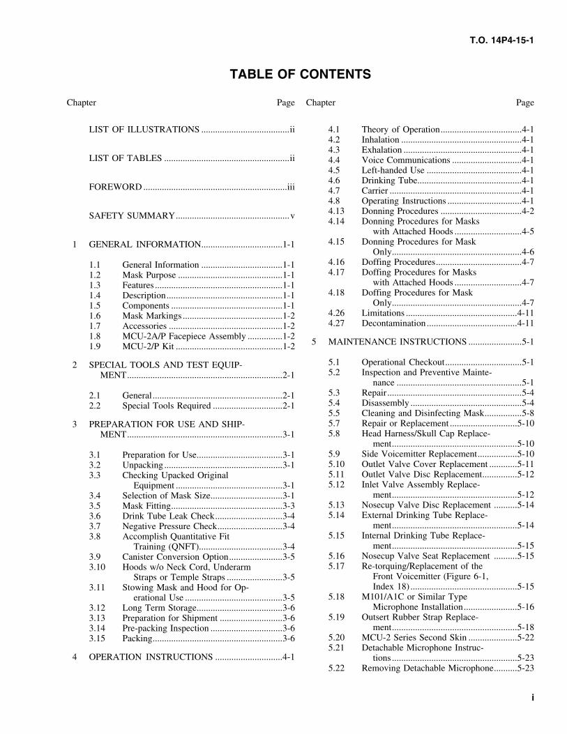
TABLE OF CONTENTS
Chapter Page Chapter Page
LIST OF ILLUSTRATIONS ......................................ii 4.1 Theory of Operation...................................4-14.2 Inhalation ....................................................4-14.3 Exhalation ...................................................4-1
LIST OF TABLES ......................................................ii 4.4 Voice Communications ..............................4-14.5 Left-handed Use .........................................4-14.6 Drinking Tube.............................................4-1
FOREWORD ..............................................................iii 4.7 Carrier .........................................................4-14.8 Operating Instructions ................................4-14.13 Donning Procedures ...................................4-2SAFETY SUMMARY.................................................v4.14 Donning Procedures for Masks
with Attached Hoods .............................4-54.15 Donning Procedures for Mask1 GENERAL INFORMATION...................................1-1
Only........................................................4-64.16 Doffing Procedures.....................................4-71.1 General Information ...................................1-14.17 Doffing Procedures for Masks1.2 Mask Purpose .............................................1-1
with Attached Hoods .............................4-71.3 Features .......................................................1-14.18 Doffing Procedures for Mask1.4 Description..................................................1-1
Only........................................................4-71.5 Components ................................................1-14.26 Limitations ................................................4-111.6 Mask Markings ...........................................1-24.27 Decontamination .......................................4-111.7 Accessories .................................................1-2
1.8 MCU-2A/P Facepiece Assembly ...............1-25 MAINTENANCE INSTRUCTIONS .......................5-11.9 MCU-2/P Kit ..............................................1-2
5.1 Operational Checkout.................................5-12 SPECIAL TOOLS AND TEST EQUIP-5.2 Inspection and Preventive Mainte-MENT...................................................................2-1
nance ......................................................5-15.3 Repair..........................................................5-42.1 General........................................................2-15.4 Disassembly ................................................5-42.2 Special Tools Required ..............................2-15.5 Cleaning and Disinfecting Mask................5-85.7 Repair or Replacement .............................5-103 PREPARATION FOR USE AND SHIP-5.8 Head Harness/Skull Cap Replace-MENT...................................................................3-1
ment......................................................5-105.9 Side Voicemitter Replacement.................5-103.1 Preparation for Use.....................................3-15.10 Outlet Valve Cover Replacement ............5-113.2 Unpacking ...................................................3-15.11 Outlet Valve Disc Replacement...............5-123.3 Checking Upacked Original5.12 Inlet Valve Assembly Replace-Equipment ..............................................3-1
ment......................................................5-123.4 Selection of Mask Size...............................3-15.13 Nosecup Valve Disc Replacement ..........5-143.5 Mask Fitting................................................3-35.14 External Drinking Tube Replace-3.6 Drink Tube Leak Check.............................3-4
ment......................................................5-143.7 Negative Pressure Check............................3-45.15 Internal Drinking Tube Replace-3.8 Accomplish Quantitative Fit
ment......................................................5-15Training (QNFT)....................................3-45.16 Nosecup Valve Seat Replacement ..........5-153.9 Canister Conversion Option.......................3-55.17 Re-torquing/Replacement of the3.10 Hoods w/o Neck Cord, Underarm
Front Voicemitter (Figure 6-1,Straps or Temple Straps ........................3-5Index 18) ..............................................5-153.11 Stowing Mask and Hood for Op-
5.18 M101/A1C or Similar Typeerational Use ..........................................3-5Microphone Installation.......................5-163.12 Long Term Storage.....................................3-6
5.19 Outsert Rubber Strap Replace-3.13 Preparation for Shipment ...........................3-6ment......................................................5-183.14 Pre-packing Inspection ...............................3-6
5.20 MCU-2 Series Second Skin .....................5-223.15 Packing........................................................3-65.21 Detachable Microphone Instruc-
4 OPERATION INSTRUCTIONS .............................4-1 tions ......................................................5-235.22 Removing Detachable Microphone..........5-23
i
T.O. 14P4-15-1
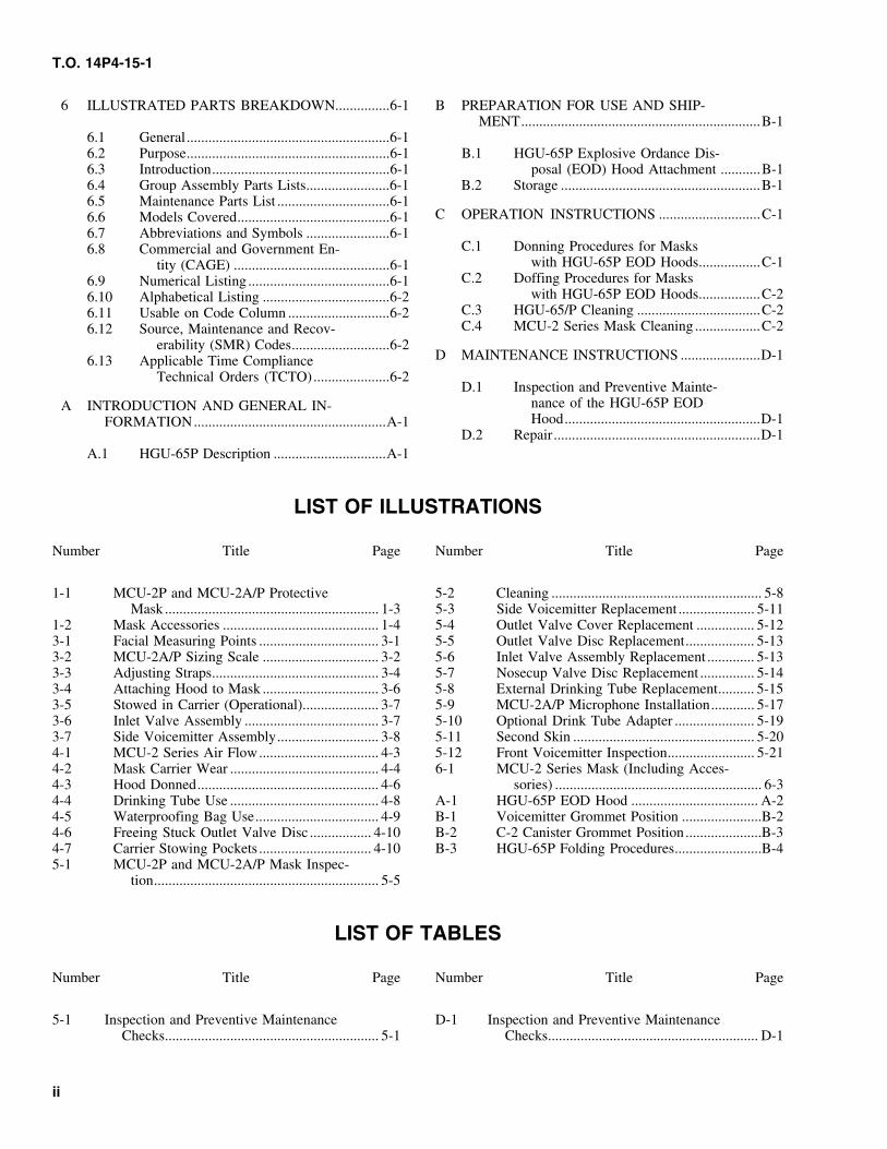
6 ILLUSTRATED PARTS BREAKDOWN...............6-1 B PREPARATION FOR USE AND SHIP-MENT..................................................................B-1
6.1 General........................................................6-16.2 Purpose........................................................6-1 B.1 HGU-65P Explosive Ordance Dis-6.3 Introduction.................................................6-1 posal (EOD) Hood Attachment ...........B-16.4 Group Assembly Parts Lists.......................6-1 B.2 Storage .......................................................B-16.5 Maintenance Parts List ...............................6-1
C OPERATION INSTRUCTIONS ............................C-16.6 Models Covered..........................................6-16.7 Abbreviations and Symbols .......................6-1
C.1 Donning Procedures for Masks6.8 Commercial and Government En-with HGU-65P EOD Hoods.................C-1tity (CAGE) ...........................................6-1
C.2 Doffing Procedures for Masks6.9 Numerical Listing .......................................6-1with HGU-65P EOD Hoods.................C-26.10 Alphabetical Listing ...................................6-2
C.3 HGU-65/P Cleaning ..................................C-26.11 Usable on Code Column ............................6-2C.4 MCU-2 Series Mask Cleaning ..................C-26.12 Source, Maintenance and Recov-
erability (SMR) Codes...........................6-2D MAINTENANCE INSTRUCTIONS ......................D-16.13 Applicable Time Compliance
Technical Orders (TCTO).....................6-2D.1 Inspection and Preventive Mainte-
nance of the HGU-65P EODA INTRODUCTION AND GENERAL IN-Hood......................................................D-1FORMATION.....................................................A-1
D.2 Repair.........................................................D-1A.1 HGU-65P Description ...............................A-1
LIST OF ILLUSTRATIONS
Number Title Page Number Title Page
1-1 MCU-2P and MCU-2A/P Protective 5-2 Cleaning .......................................................... 5-8Mask ........................................................... 1-3 5-3 Side Voicemitter Replacement ..................... 5-11
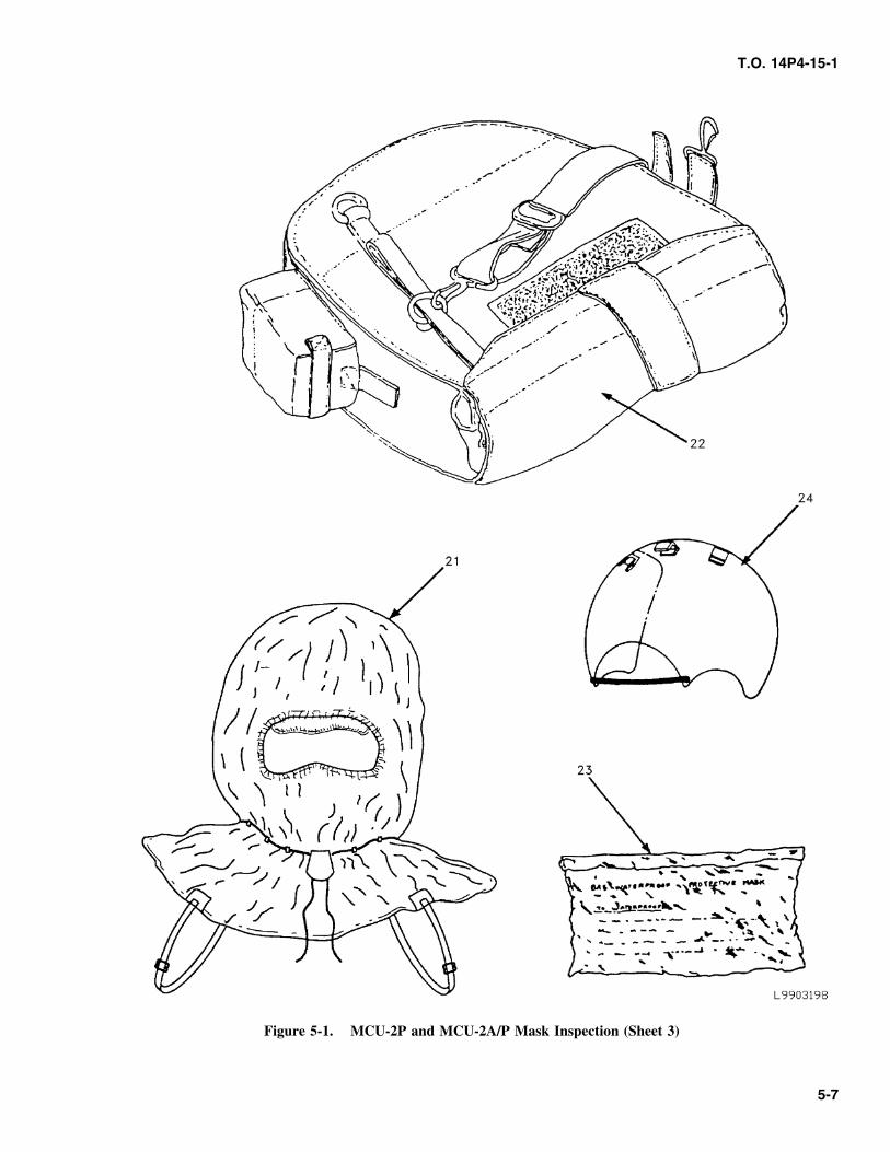
1-2 Mask Accessories ........................................... 1-4 5-4 Outlet Valve Cover Replacement ................ 5-123-1 Facial Measuring Points ................................. 3-1 5-5 Outlet Valve Disc Replacement................... 5-133-2 MCU-2A/P Sizing Scale ................................ 3-2 5-6 Inlet Valve Assembly Replacement ............. 5-133-3 Adjusting Straps.............................................. 3-4 5-7 Nosecup Valve Disc Replacement ............... 5-143-4 Attaching Hood to Mask ................................ 3-6 5-8 External Drinking Tube Replacement.......... 5-153-5 Stowed in Carrier (Operational)..................... 3-7 5-9 MCU-2A/P Microphone Installation............ 5-173-6 Inlet Valve Assembly ..................................... 3-7 5-10 Optional Drink Tube Adapter ...................... 5-193-7 Side Voicemitter Assembly............................ 3-8 5-11 Second Skin .................................................. 5-204-1 MCU-2 Series Air Flow................................. 4-3 5-12 Front Voicemitter Inspection........................ 5-214-2 Mask Carrier Wear ......................................... 4-4 6-1 MCU-2 Series Mask (Including Acces-4-3 Hood Donned.................................................. 4-6 sories) ......................................................... 6-34-4 Drinking Tube Use ......................................... 4-8 A-1 HGU-65P EOD Hood ................................... A-24-5 Waterproofing Bag Use.................................. 4-9 B-1 Voicemitter Grommet Position ......................B-24-6 Freeing Stuck Outlet Valve Disc ................. 4-10 B-2 C-2 Canister Grommet Position.....................B-34-7 Carrier Stowing Pockets ............................... 4-10 B-3 HGU-65P Folding Procedures........................B-45-1 MCU-2P and MCU-2A/P Mask Inspec-
tion.............................................................. 5-5
LIST OF TABLES
Number Title Page Number Title Page
5-1 Inspection and Preventive Maintenance D-1 Inspection and Preventive MaintenanceChecks........................................................... 5-1 Checks.......................................................... D-1
ii
T.O. 14P4-15-1
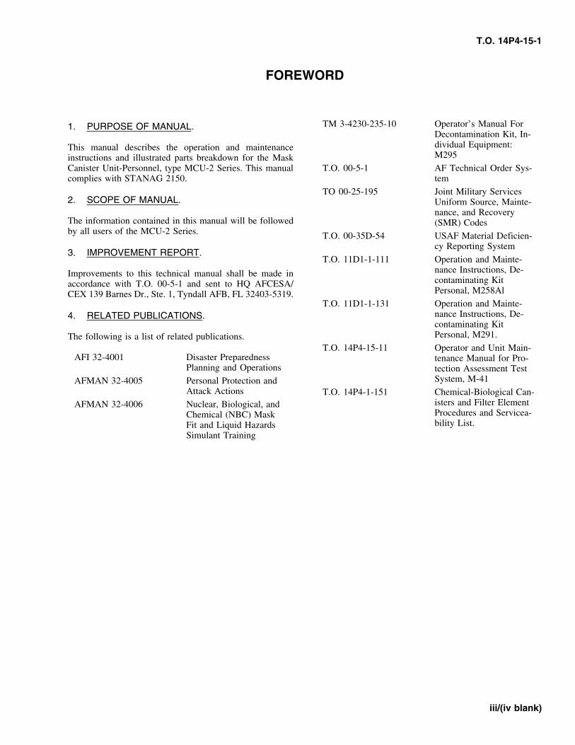
FOREWORD
TM 3-4230-235-10 Operator’s Manual For1. PURPOSE OF MANUAL.Decontamination Kit, In-dividual Equipment:This manual describes the operation and maintenanceM295instructions and illustrated parts breakdown for the Mask
Canister Unit-Personnel, type MCU-2 Series. This manual T.O. 00-5-1 AF Technical Order Sys-complies with STANAG 2150. tem
TO 00-25-195 Joint Military Services2. SCOPE OF MANUAL. Uniform Source, Mainte-
nance, and RecoveryThe information contained in this manual will be followed (SMR) Codesby all users of the MCU-2 Series. T.O. 00-35D-54 USAF Material Deficien-
cy Reporting System3. IMPROVEMENT REPORT.
T.O. 11D1-1-111 Operation and Mainte-nance Instructions, De-Improvements to this technical manual shall be made incontaminating Kitaccordance with T.O. 00-5-1 and sent to HQ AFCESA/Personal, M258AlCEX 139 Barnes Dr., Ste. 1, Tyndall AFB, FL 32403-5319.
T.O. 11D1-1-131 Operation and Mainte-nance Instructions, De-4. RELATED PUBLICATIONS.contaminating KitPersonal, M291.The following is a list of related publications.
T.O. 14P4-15-11 Operator and Unit Main-AFI 32-4001 Disaster Preparedness tenance Manual for Pro-
Planning and Operations tection Assessment TestSystem, M-41AFMAN 32-4005 Personal Protection and
Attack Actions T.O. 14P4-1-151 Chemical-Biological Can-isters and Filter ElementAFMAN 32-4006 Nuclear, Biological, andProcedures and Servicea-Chemical (NBC) Maskbility List.Fit and Liquid Hazards
Simulant Training
iii/(iv blank)

T.O. 14P4-15-1
SAFETY SUMMARY
1. This technical manual contains CAUTIONS andWARNINGS applicable to the use of the MCU-2 Series WARNINGmask. Before using the mask, personnel should be aware ofthe hazards which could be encountered, especially in acontaminated environment. Special attention to the instruc- You must check the mask for leaks when it istions in this manual will assure safe wear of the MCU-2 fitted and each time you put it on. A leakySeries series protective mask and accessories. mask will not protect you from toxic agents
which can cause illness or death.2. WARNING.
WARNINGAn operating or maintenance procedure, practice, condi-tion, statement, etc., which, if not strictly observed, couldresult in injury or death of personnel.
If resistance is not felt when blowing into orsucking through the drinking tube, a leak is
3. CAUTION. present and toxic agents may enter the mask.
An operating or maintenance procedure, practice, condi-tion, statement, etc., which, if not strictly observed, could WARNINGresult in damage to or destruction of equipment or loss ofmission effectiveness.
Perform the steps for putting on your maskquickly. You must put the mask on before you4. USE OF SHALL, WILL, SHOULD AND MAY.take another breath. Toxic agents may be in thesurrounding air and can cause illness or death.a. SHALL OR WILL: “Shall or will” indicates a
mandatory requirement.
WARNINGb. SHOULD: “Should” is used to indicate a non-mandatory desire or preferred method ofaccomplishment. Do not store food in the waterproofing bag.
Possible toxic effects may result.c. MAY: “May” is used to indicate an acceptable orsuggested means of accomplishment.
WARNING5. The following warnings and cautions appear in thetext of this manual and are repeated here for emphasis:
The MCU-2 Series mask is not an authorizedrespiratory device for industrial chemical use.
WARNING The chemical biological filter canister will notprotect against ammonia or carbon monoxide,and the mask is not effective in confined spacesFor initial mask fit, use the caliper to measurewhere there is not enough oxygen in the air tothe face length. The use of a ruler or tapesupport life.measure will lead to inaccurate reading due to
the contour of the face. A leaking mask will notprotect against toxic agents which can cause WARNINGillness or death.
When wearing the mask with the hood overWARNING outlet valve (Figure 4-3), do not loosen the
straps of the head harness for comfort. Whenstraps are loosened, the wearer is in danger ofDo not hold mask by canister. A canister whichsuffocation by carbon dioxide and unprotectedhas unscrewed may allow toxic agents to enteragainst toxic agents.the mask which can cause illness or death.
v
T.O. 14P4-15-1
WARNING WARNING
If you become overheated in cold weather, Failure to perform the Negative Pressure Checkwhen possible do not remove your mask out- may result in illness or death due to exposure todoors until your head cools and any sweat has chemical agents.dried. Frostbite may result if the mask isremoved while your face is still wet.
WARNING
WARNINGContact lenses shall not be worn with thismask.
With suspected presence of contamination, donyour mask immediately. You must put the
WARNINGmask on before you take another breath. Toxicagents may be in the surrounding air and cancause illness or death. Failure to loosen the bottom straps on the mask
prior to removing the mask will place excessiveand undue stress on the outlet valve assembly.WARNINGThis stress on the outlet valve assembly willcontribute to disbonding of the mask.
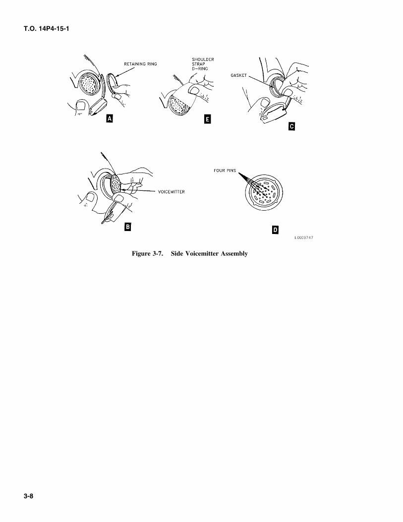
Make sure side voicemitter is installed with theflange and four pins facing outward (Figure 3-
WARNING7, view D). Incorrect installation may result inleakage of toxic agents into the mask causingillness or death. When in a contaminated environment, pressure
shall be applied to the front voicemitter (usingtwo fingers) prior to removing the hood toWARNINGprevent mask seal from being broken. Breakageof the mask seal can cause illness or death.
The side voicemitter must be installed using aserviceable gasket. Use of an UNSERVICE-ABLE gasket could result in leakage of toxicagents causing illness or death.
WARNING
A serviceable C-2 series canister must beinstalled in the MCU-2 Series mask prior to usein a toxic chemical or biological environment.
vi
T.O. 14P4-15-1
CHAPTER 1GENERAL INFORMATION
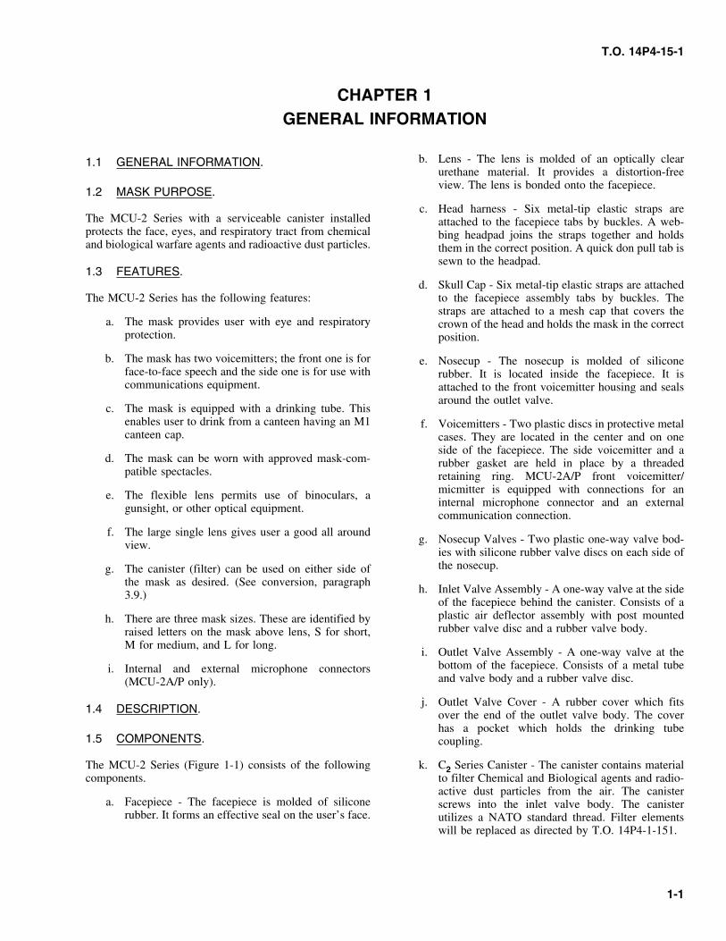
b. Lens - The lens is molded of an optically clear1.1 GENERAL INFORMATION.urethane material. It provides a distortion-freeview. The lens is bonded onto the facepiece.
1.2 MASK PURPOSE.c. Head harness - Six metal-tip elastic straps are
The MCU-2 Series with a serviceable canister installed attached to the facepiece tabs by buckles. A web-protects the face, eyes, and respiratory tract from chemical bing headpad joins the straps together and holdsand biological warfare agents and radioactive dust particles. them in the correct position. A quick don pull tab is
sewn to the headpad.1.3 FEATURES.
d. Skull Cap - Six metal-tip elastic straps are attachedThe MCU-2 Series has the following features: to the facepiece assembly tabs by buckles. The
straps are attached to a mesh cap that covers thea. The mask provides user with eye and respiratory crown of the head and holds the mask in the correct
protection. position.
b. The mask has two voicemitters; the front one is for e. Nosecup - The nosecup is molded of siliconeface-to-face speech and the side one is for use with rubber. It is located inside the facepiece. It iscommunications equipment. attached to the front voicemitter housing and seals
around the outlet valve.c. The mask is equipped with a drinking tube. This
enables user to drink from a canteen having an M1 f. Voicemitters - Two plastic discs in protective metalcanteen cap. cases. They are located in the center and on one
side of the facepiece. The side voicemitter and ad. The mask can be worn with approved mask-com- rubber gasket are held in place by a threaded
patible spectacles. retaining ring. MCU-2A/P front voicemitter/micmitter is equipped with connections for ane. The flexible lens permits use of binoculars, ainternal microphone connector and an externalgunsight, or other optical equipment.communication connection.
f. The large single lens gives user a good all aroundg. Nosecup Valves - Two plastic one-way valve bod-view.
ies with silicone rubber valve discs on each side ofthe nosecup.g. The canister (filter) can be used on either side of
the mask as desired. (See conversion, paragraphh. Inlet Valve Assembly - A one-way valve at the side3.9.)
of the facepiece behind the canister. Consists of aplastic air deflector assembly with post mountedh. There are three mask sizes. These are identified byrubber valve disc and a rubber valve body.raised letters on the mask above lens, S for short,
M for medium, and L for long.i. Outlet Valve Assembly - A one-way valve at the
bottom of the facepiece. Consists of a metal tubei. Internal and external microphone connectorsand valve body and a rubber valve disc.(MCU-2A/P only).
j. Outlet Valve Cover - A rubber cover which fits1.4 DESCRIPTION. over the end of the outlet valve body. The cover
has a pocket which holds the drinking tube1.5 COMPONENTS. coupling.
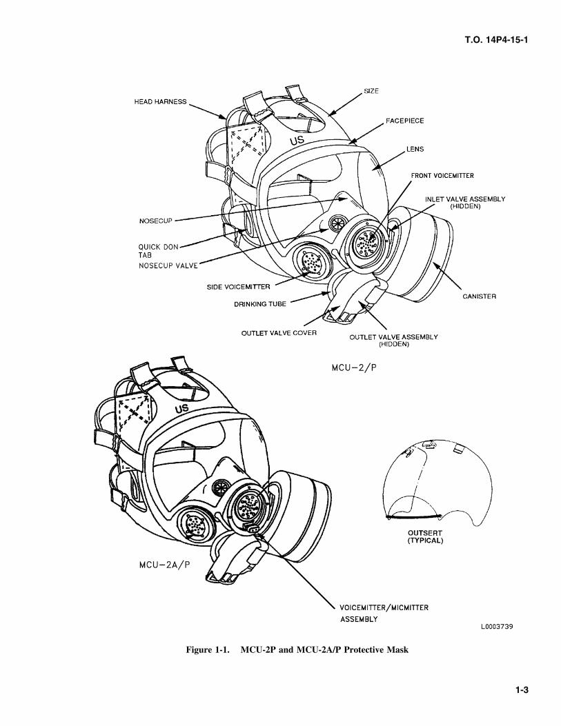
The MCU-2 Series (Figure 1-1) consists of the following k. C2 Series Canister - The canister contains materialcomponents. to filter Chemical and Biological agents and radio-
active dust particles from the air. The canistera. Facepiece - The facepiece is molded of silicone screws into the inlet valve body. The canister
rubber. It forms an effective seal on the user’s face. utilizes a NATO standard thread. Filter elementswill be replaced as directed by T.O. 14P4-1-151.
1-1
T.O. 14P4-15-1
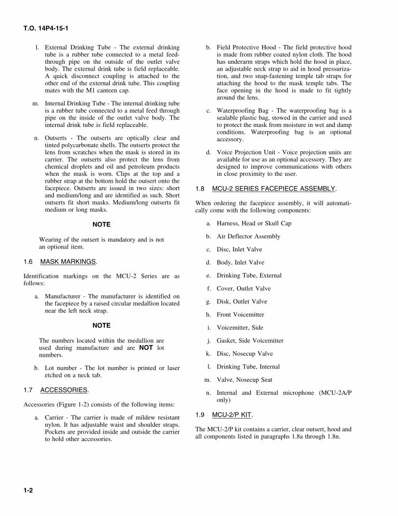
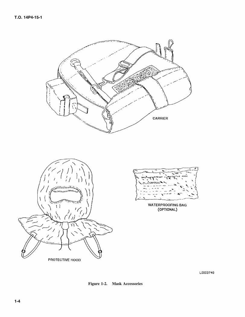
l. External Drinking Tube - The external drinking b. Field Protective Hood - The field protective hoodtube is a rubber tube connected to a metal feed- is made from rubber coated nylon cloth. The hoodthrough pipe on the outside of the outlet valve has underarm straps which hold the hood in place,body. The external drink tube is field replaceable. an adjustable neck strap to aid in hood pressuriza-A quick disconnect coupling is attached to the tion, and two snap-fastening temple tab straps forother end of the external drink tube. This coupling attaching the hood to the mask temple tabs. Themates with the M1 canteen cap. face opening in the hood is made to fit tightly
around the lens.m. Internal Drinking Tube - The internal drinking tube
is a rubber tube connected to a metal feed through c. Waterproofing Bag - The waterproofing bag is apipe on the inside of the outlet valve body. The sealable plastic bag, stowed in the carrier and usedinternal drink tube is field replaceable. to protect the mask from moisture in wet and damp
conditions. Waterproofing bag is an optionaln. Outserts - The outserts are optically clear and accessory.
tinted polycarbonate shells. The outserts protect thelens from scratches when the mask is stored in its d. Voice Projection Unit - Voice projection units arecarrier. The outserts also protect the lens from available for use as an optional accessory. They arechemical droplets and oil and petroleum products designed to improve communications with otherswhen the mask is worn. Clips at the top and a in close proximity to the user.rubber strap at the bottom hold the outsert onto thefacepiece. Outserts are issued in two sizes: short 1.8 MCU-2 SERIES FACEPIECE ASSEMBLY.and medium/long and are identified as such. Shortoutserts fit short masks. Medium/long outserts fit When ordering the facepiece assembly, it will automati-medium or long masks. cally come with the following components:
a. Harness, Head or Skull CapNOTE
b. Air Deflector AssemblyWearing of the outsert is mandatory and is notan optional item. c. Disc, Inlet Valve
1.6 MASK MARKINGS. d. Body, Inlet Valve
e. Drinking Tube, ExternalIdentification markings on the MCU-2 Series are asfollows:
f. Cover, Outlet Valvea. Manufacturer - The manufacturer is identified on
g. Disk, Outlet Valvethe facepiece by a raised circular medallion locatednear the left neck strap.
h. Front Voicemitter
NOTE i. Voicemitter, Side
The numbers located within the medallion are j. Gasket, Side Voicemitterused during manufacture and are NOT lot
k. Disc, Nosecup Valvenumbers.
l. Drinking Tube, Internalb. Lot number - The lot number is printed or laseretched on a neck tab.
m. Valve, Nosecup Seat
1.7 ACCESSORIES. n. Internal and External microphone (MCU-2A/Ponly)
Accessories (Figure 1-2) consists of the following items:
1.9 MCU-2/P KIT.a. Carrier - The carrier is made of mildew resistantnylon. It has adjustable waist and shoulder straps.
The MCU-2/P kit contains a carrier, clear outsert, hood andPockets are provided inside and outside the carrierall components listed in paragraphs 1.8a through 1.8n.to hold other accessories.
1-2
T.O. 14P4-15-1
Figure 1-1. MCU-2P and MCU-2A/P Protective Mask
1-3
T.O. 14P4-15-1
Figure 1-2. Mask Accessories
1-4
T.O. 14P4-15-1
CHAPTER 2SPECIAL TOOLS AND TEST EQUIPMENT
c. Torque Wrench, 3/8 inch male drive, 30-150 in - lb2.1 GENERAL.gradated, NSN 5120-01-396-6017
This chapter describes the special tools and test equipmentd. TDA 99M or an approved Joint Service Maskused to perform maintenance on the Chemical-Biological
Leakage Tester (JSMLT)Mask.
e. M41, Protection Assessment Test System2.2 SPECIAL TOOLS REQUIRED.
2.3 The special tools required are listed below:
a. Six inch Calipers
b. Front Voicemitter Tool, part No. 200224199, Cage98752
2-1/(2-2 blank)

T.O. 14P4-15-1
CHAPTER 3PREPARATION FOR USE AND SHIPMENT
c. Carefully locate and mark upper and lower measur-3.1 PREPARATION FOR USE.ing points.
3.2 UNPACKING. d. Place upper and lower tips of the caliper directly onthe upper and lower points marked as directed in
Remove mask and components from shipping container. step c.
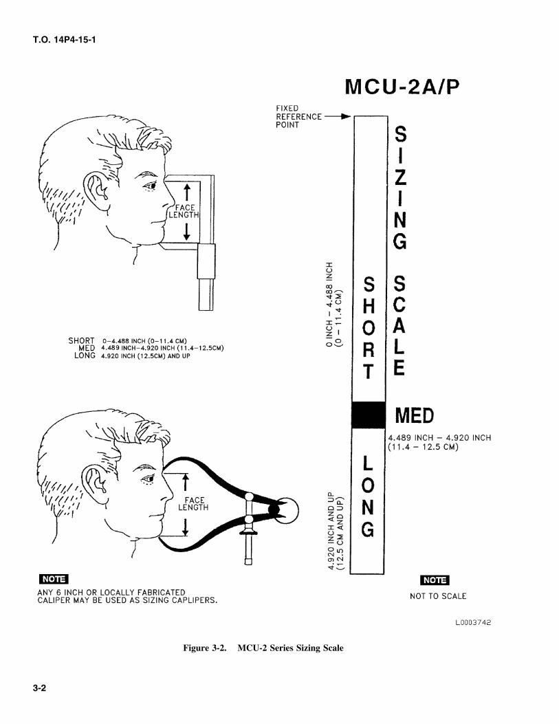
3.3 CHECKING UPACKED ORIGINAL e. To determine the initial mask size with any 6-inchcaliper, see Figure 3-2 for sample MCU-2 SeriesEQUIPMENT.Sizing Scale.
Inspect the equipment for damage following criteria inNOTETable 5-1. Report damage according to T.O. 00-35D-54,
USAF Material Deficiency Reporting and InvestigatingA sizing scale can be made by utilizing theSystem.measurements provided in the sample scale inFigure 3-2.3.4 SELECTION OF MASK SIZE.
Initial mask size selection is determined by a face lengthmeasurement. The use of any 6-inch calipers, is required tomeasure the user’s face length.
WARNING
Use a caliper to measure the face length. Theuse of a ruler or tape measure will lead to aninaccurate reading due to the contour of theface. A leaky mask will not protect againsttoxic agents which can cause illness or death.
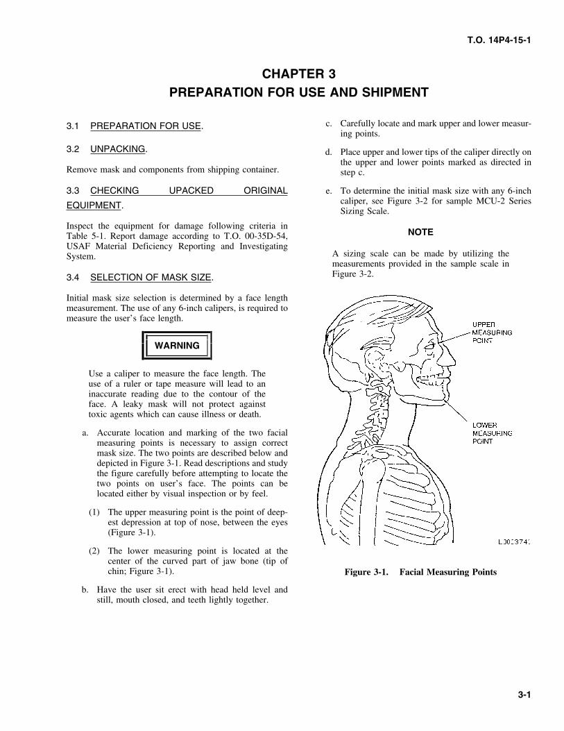
a. Accurate location and marking of the two facialmeasuring points is necessary to assign correctmask size. The two points are described below anddepicted in Figure 3-1. Read descriptions and studythe figure carefully before attempting to locate thetwo points on user’s face. The points can belocated either by visual inspection or by feel.
(1) The upper measuring point is the point of deep-est depression at top of nose, between the eyes(Figure 3-1).
(2) The lower measuring point is located at thecenter of the curved part of jaw bone (tip ofchin; Figure 3-1). Figure 3-1. Facial Measuring Points
b. Have the user sit erect with head held level andstill, mouth closed, and teeth lightly together.
3-1
T.O. 14P4-15-1
Figure 3-2. MCU-2 Series Sizing Scale
3-2
T.O. 14P4-15-1
position with one hand until temple straps are3.5 MASK FITTING.tightened.
A correctly adjusted mask is necessary for proper fit and toprevent leaks. To adjust the mask, the following procedures WARNINGshould be used:
Women will remove hair fasteners (hair clips,WARNING pins) and let hair hang freely before donning
mask. When wearing Ground Crew Ensemble(GCE), hair will be neatly tucked inside jacket.Failure to follow instructions as prescribed inFailure to do so could result in an improperparagraph 3.5 could result in improper mask fitmask fit resulting in illness or death.causing the mask to leak.
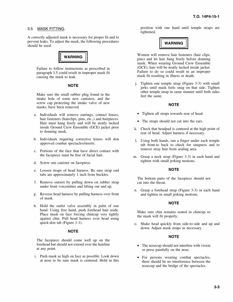
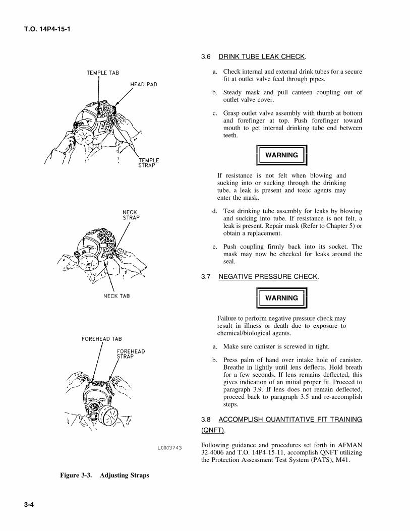
j. Tighten one temple strap (Figure 3-3) with smallNOTE jerks until mask feels snug on that side. Tighten
other temple strap in same manner until both sidesMake sure the small rubber plug found in the feel the same.intake hole of some new canisters, and thescrew cap protecting the intake valve of new NOTEmasks, have been removed.
• Tighten all straps towards rear of head.a. Individuals will remove earrings, contact lenses,hair fasteners (hairclips, pins, etc.,) and hairpieces. • The straps should not cut into the ears.Hair must hang freely and will be neatly tuckedinside Ground Crew Ensemble (GCE) jacket prior k. Check that headpad is centered at the high point ofto donning mask. rear of head. Adjust harness if necessary.
b. Individuals requiring corrective lenses will don l. Using both hands, run a finger under each templeapproved combat spectacles/inserts. tab front-to back to check for snugness and to
remove stray hair from sealing area.c. Portions of the face that have direct contact withthe facepiece must be free of facial hair. m. Grasp a neck strap (Figure 3-3) in each hand and
tighten with small jerking motions.d. Screw one canister on facepiece.
NOTEe. Loosen straps of head harness. Be sure strap endtabs are approximately 1 inch from buckles.
The bottom parts of the facepiece should notf. Remove outsert by pulling down on rubber strap cut into the throat.
under front voicemitter and lifting out and up.n. Grasp a forehead strap (Figure 3-3) in each hand
g. Reverse head harness by pulling harness over front and tighten in small jerking motions.of mask.
NOTEh. Hold the outlet valve assembly in palm of one
hand. Using free hand, push forehead hair aside. Make sure chin remains seated in chincup soPlace mask on face forcing chincup very tightly the mask will fit properly.against chin. Pull head harness over head usingquick-don tab (Figure 1-1). o. Shake head quickly from side-to-side and up and
down. Adjust mask straps as necessary.NOTE
NOTEThe facepiece should come well up on theforehead but should not extend over the hairline • The nosecup should not interfere with visionat any point. or press painfully on the nose.
i. Push mask as high on face as possible. Look down • For persons wearing combat spectacles,at nose to be sure mask is centered. Hold in this there should be no interference between the
nosecup and the bridge of the spectacles.
3-3
T.O. 14P4-15-1
3.6 DRINK TUBE LEAK CHECK.
a. Check internal and external drink tubes for a securefit at outlet valve feed through pipes.
b. Steady mask and pull canteen coupling out ofoutlet valve cover.
c. Grasp outlet valve assembly with thumb at bottomand forefinger at top. Push forefinger towardmouth to get internal drinking tube end betweenteeth.
WARNING
If resistance is not felt when blowing andsucking into or sucking through the drinkingtube, a leak is present and toxic agents mayenter the mask.
d. Test drinking tube assembly for leaks by blowingand sucking into tube. If resistance is not felt, aleak is present. Repair mask (Refer to Chapter 5) orobtain a replacement.
e. Push coupling firmly back into its socket. Themask may now be checked for leaks around theseal.
3.7 NEGATIVE PRESSURE CHECK.
WARNING
Failure to perform negative pressure check mayresult in illness or death due to exposure tochemical/biological agents.
a. Make sure canister is screwed in tight.
b. Press palm of hand over intake hole of canister.Breathe in lightly until lens deflects. Hold breathfor a few seconds. If lens remains deflected, thisgives indication of an initial proper fit. Proceed toparagraph 3.9. If lens does not remain deflected,proceed back to paragraph 3.5 and re-accomplishsteps.
3.8 ACCOMPLISH QUANTITATIVE FIT TRAINING
(QNFT).
Following guidance and procedures set forth in AFMAN32-4006 and T.O. 14P4-15-11, accomplish QNFT utilizingthe Protection Assessment Test System (PATS), M41.
Figure 3-3. Adjusting Straps
3-4
T.O. 14P4-15-1
NOTEWARNING
Leaks around the edge of the mask are usuallycaused by bad fit. Most leaks may be found by • Make sure side voicemitter is installed withfeeling incoming air on the face or locating the flange and four pins facing outwardwith a finger. Make sure the harness head pad (Figure 3-7, view D). Incorrect installationis centered at the high point on the rear of head. will result in leakage of toxic agents into the
mask causing illness or death.3.9 CANISTER CONVERSION OPTION.
• Visually inspect voicemitter gasket for cuts,distortion or damage. If any doubt existsThe filter canister may be mounted on either the left orregarding its integrity replace with a newright side of the mask as desired. To reverse the positionsserviceable gasket.of the inlet valve assembly/canister, and the side voicemit-
ter, proceed as follows:k. Install gasket and voicemitter in remaining port.
Screw in voicemitter retaining ring (slots outwards)a. Remove canister (if installed).and tighten with carrier D-ring.
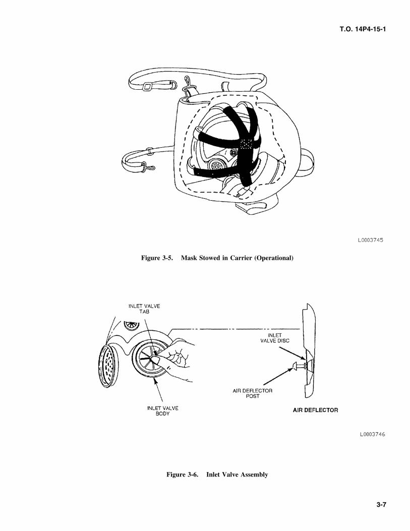
b. Gently push center of valve body (Figure 3-6) untill. Perform Negative Pressure Check (paragraph 3.7).it pops through port.
c. Remove assembly from inside facepiece. 3.10 HOODS W/O NECK CORD, UNDERARM
STRAPS OR TEMPLE STRAPS.d. Pull inlet valve body from air deflector post.
A limited number of early production hoods are note. With the straight side of carrier shoulder strap D-equipped with a neck cord, underarm straps or templering, unscrew and take out side voicemitter retain-straps and cannot be attached to the mask. These typeing ring, voicemitter and gasket (Figure 3-7, viewshoods are no longer authorized for use with the MCU-2A, B, C, D and E). Discard gasket (ifSeries mask.UNSERVICEABLE).
f. Push inlet valve body in desired port. Make sure 3.11 STOWING MASK AND HOOD FORinlet valve body is seated in facepiece side port.
OPERATIONAL USE.g. Make sure inlet valve disc is seated in the lower
Attach hood to mask as follows:slot (narrowest) of the air deflector post.
a. Unfold hood and loosen neck cord.h. From inside facepiece, push air deflector assemblyinto valve body while holding valve body in port.
b. Turn hood inside out.Head of air deflector post must stick through holein center of valve body. Side edges of air deflector c. Spread hood flat, with the face opening up.should be between the raised parallel guides oninside of facepiece. d. Unfasten underarm straps and hood temple straps
(Figure 3-4).i. Rotate valve body using tabs to verify correct
seating. e. Place mask face down on hood and insert thecanister through face opening. Adjust mask neck
j. Screw canister into facepiece and handtighten. straps so ends are within 1 inch of buckles.
f. Fasten hood temple straps over mask temple tabs.
g. Turn hood right side out.
h. Stretch hood face opening around top and sides ofmask lens.
i. Make sure hood covers top of the outlet valvecover.
j. If hood is to be worn in a biological or radiologicalenvironment with temperatures below 30°F (-1°C)or above 90°F (32°C), stretch lower part of face
3-5
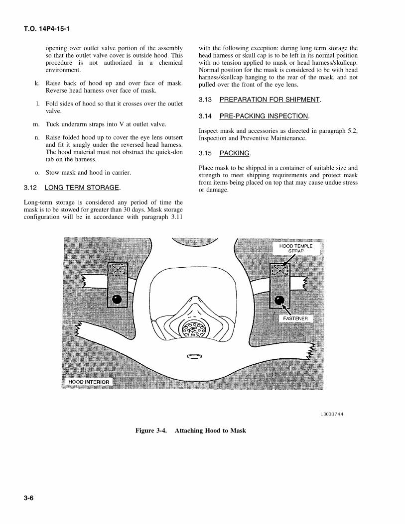
T.O. 14P4-15-1
opening over outlet valve portion of the assembly with the following exception: during long term storage theso that the outlet valve cover is outside hood. This head harness or skull cap is to be left in its normal positionprocedure is not authorized in a chemical with no tension applied to mask or head harness/skullcap.environment. Normal position for the mask is considered to be with head
harness/skullcap hanging to the rear of the mask, and notk. Raise back of hood up and over face of mask. pulled over the front of the eye lens.
Reverse head harness over face of mask.
3.13 PREPARATION FOR SHIPMENT.l. Fold sides of hood so that it crosses over the outlet
valve.3.14 PRE-PACKING INSPECTION.
m. Tuck underarm straps into V at outlet valve.Inspect mask and accessories as directed in paragraph 5.2,
n. Raise folded hood up to cover the eye lens outsert Inspection and Preventive Maintenance.and fit it snugly under the reversed head harness.The hood material must not obstruct the quick-don 3.15 PACKING.tab on the harness.
Place mask to be shipped in a container of suitable size ando. Stow mask and hood in carrier. strength to meet shipping requirements and protect mask
from items being placed on top that may cause undue stress3.12 LONG TERM STORAGE. or damage.
Long-term storage is considered any period of time themask is to be stowed for greater than 30 days. Mask storageconfiguration will be in accordance with paragraph 3.11
Figure 3-4. Attaching Hood to Mask
3-6
T.O. 14P4-15-1
Figure 3-5. Mask Stowed in Carrier (Operational)
Figure 3-6. Inlet Valve Assembly
3-7
T.O. 14P4-15-1
Figure 3-7. Side Voicemitter Assembly
3-8
T.O. 14P4-15-1
CHAPTER 4OPERATION INSTRUCTIONS
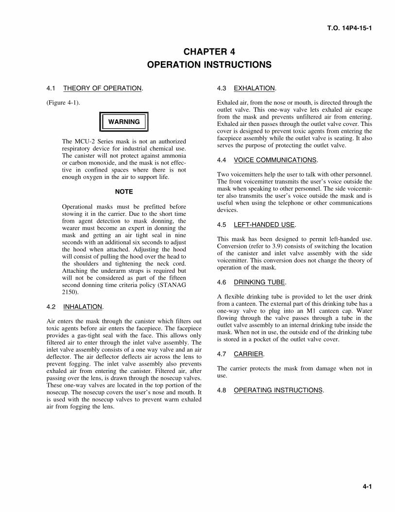
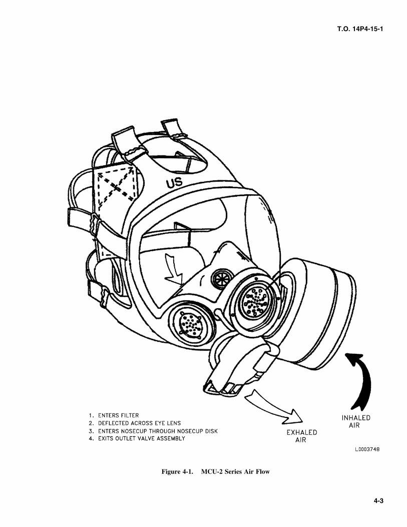
4.1 THEORY OF OPERATION. 4.3 EXHALATION.
(Figure 4-1). Exhaled air, from the nose or mouth, is directed through theoutlet valve. This one-way valve lets exhaled air escapefrom the mask and prevents unfiltered air from entering.
WARNING Exhaled air then passes through the outlet valve cover. Thiscover is designed to prevent toxic agents from entering thefacepiece assembly while the outlet valve is seating. It alsoThe MCU-2 Series mask is not an authorizedserves the purpose of protecting the outlet valve.respiratory device for industrial chemical use.
The canister will not protect against ammonia4.4 VOICE COMMUNICATIONS.or carbon monoxide, and the mask is not effec-
tive in confined spaces where there is notTwo voicemitters help the user to talk with other personnel.enough oxygen in the air to support life.The front voicemitter transmits the user’s voice outside themask when speaking to other personnel. The side voicemit-NOTEter also transmits the user’s voice outside the mask and isuseful when using the telephone or other communications
Operational masks must be prefitted before devices.stowing it in the carrier. Due to the short timefrom agent detection to mask donning, the
4.5 LEFT-HANDED USE.wearer must become an expert in donning themask and getting an air tight seal in nine
This mask has been designed to permit left-handed use.seconds with an additional six seconds to adjustConversion (refer to 3.9) consists of switching the locationthe hood when attached. Adjusting the hoodof the canister and inlet valve assembly with the sidewill consist of pulling the hood over the head tovoicemitter. This conversion does not change the theory ofthe shoulders and tightening the neck cord.operation of the mask.Attaching the underarm straps is required but
will not be considered as part of the fifteen4.6 DRINKING TUBE.second donning time criteria policy (STANAG
2150).A flexible drinking tube is provided to let the user drinkfrom a canteen. The external part of this drinking tube has a4.2 INHALATION.one-way valve to plug into an M1 canteen cap. Waterflowing through the valve passes through a tube in theAir enters the mask through the canister which filters outoutlet valve assembly to an internal drinking tube inside thetoxic agents before air enters the facepiece. The facepiecemask. When not in use, the outside end of the drinking tubeprovides a gas-tight seal with the face. This allows onlyis stored in a pocket of the outlet valve cover.filtered air to enter through the inlet valve assembly. The
inlet valve assembly consists of a one way valve and an air4.7 CARRIER.deflector. The air deflector deflects air across the lens to
prevent fogging. The inlet valve assembly also preventsThe carrier protects the mask from damage when not inexhaled air from entering the canister. Filtered air, afteruse.passing over the lens, is drawn through the nosecup valves.
These one-way valves are located in the top portion of the4.8 OPERATING INSTRUCTIONS.nosecup. The nosecup covers the user’s nose and mouth. It
is used with the nosecup valves to prevent warm exhaledair from fogging the lens.
4-1
T.O. 14P4-15-1
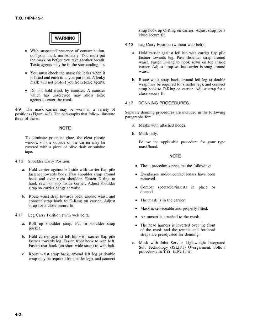
strap hook up O-Ring on carrier. Adjust strap for aclose secure fit.
WARNING
4.12 Leg Carry Position (without web belt):
• With suspected presence of contamination, a. Hold carrier against left hip with carrier flap piledon your mask immediately. You must put fastner towards leg. Pass shoulder strap aroundthe mask on before you take another breath. waist. Fasten D-ring to hook sewn on top insideToxic agents may be in the surrounding air. corner. Adjust strap so that carrier is snug around
waist.• You must check the mask for leaks when itis fitted and each time you put it on. A leaky b. Route waist strap back, around left leg (a doublemask will not protect you from toxic agents. wrap may be required for smaller leg), and connect
strap hook to O-Ring on carrier. Adjust strap for a• Do not hold mask by canister. A canisterclose secure fit.which has unscrewed may allow toxic
agents to enter the mask.4.13 DONNING PROCEDURES.
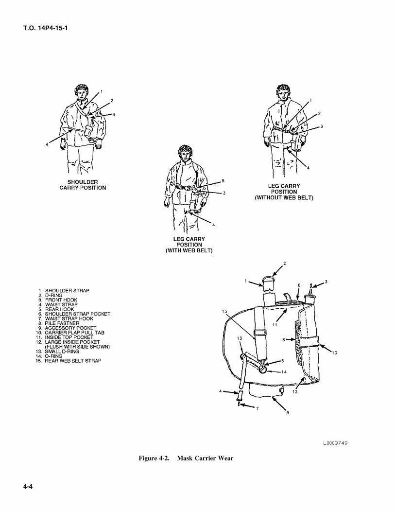
4.9 The mask carrier may be worn in a variety ofSeparate donning procedures are included in the followingpositions (Figure 4-2). The paragraphs that follow illustrateparagraphs for:three of these.
a. Masks with attached hoods.NOTE
b. Mask only.To eliminate potential glare, the clear plastic
Follow the applicable procedure for your typewindow on the outside of the carrier may bemask/hood.covered with a piece of olive drab or subdue
tape.NOTE
4.10 Shoulder Carry Position:• These procedures presume the following:
a. Hold carrier against left side with carrier flap pilefastener towards body. Pass shoulder strap around • Eyeglasses and/or contact lenses have beenback and over right shoulder. Fasten D-ring to removed.hook sewn on top inside corner. Adjust shoulder
• Combat spectacles/inserts in place orstrap so carrier hangs at waist.donned.
b. Route waist strap towards back, around waist, and• The mask is in the carrier.connect strap hook to O-Ring on carrier. Adjust
strap for a close secure fit.• Mask is serviceable and properly fitted.
4.11 Leg Carry Position (with web belt): • An outsert is attached to the mask.
a. Roll up shoulder strap. Put in shoulder strap • The head harness is inverted over the frontpocket. of the mask and the temple and forehead
straps are preadjusted for donning.b. Hold carrier against left hip with carrier flap pilefastner towards leg. Fasten front hook to web belt. c. Mask with Joint Service Lightweight IntegratedFasten rear hook (on short wide strap) to web belt. Suit Technology (JSLIST) Overgarment. Follow
procedures in T.O. 14P3-1-141.c. Route waist strap back, around left leg (a doublewrap may be required for smaller leg), and connect
4-2
T.O. 14P4-15-1
Figure 4-1. MCU-2 Series Air Flow
4-3
T.O. 14P4-15-1
Figure 4-2. Mask Carrier Wear
4-4
T.O. 14P4-15-1
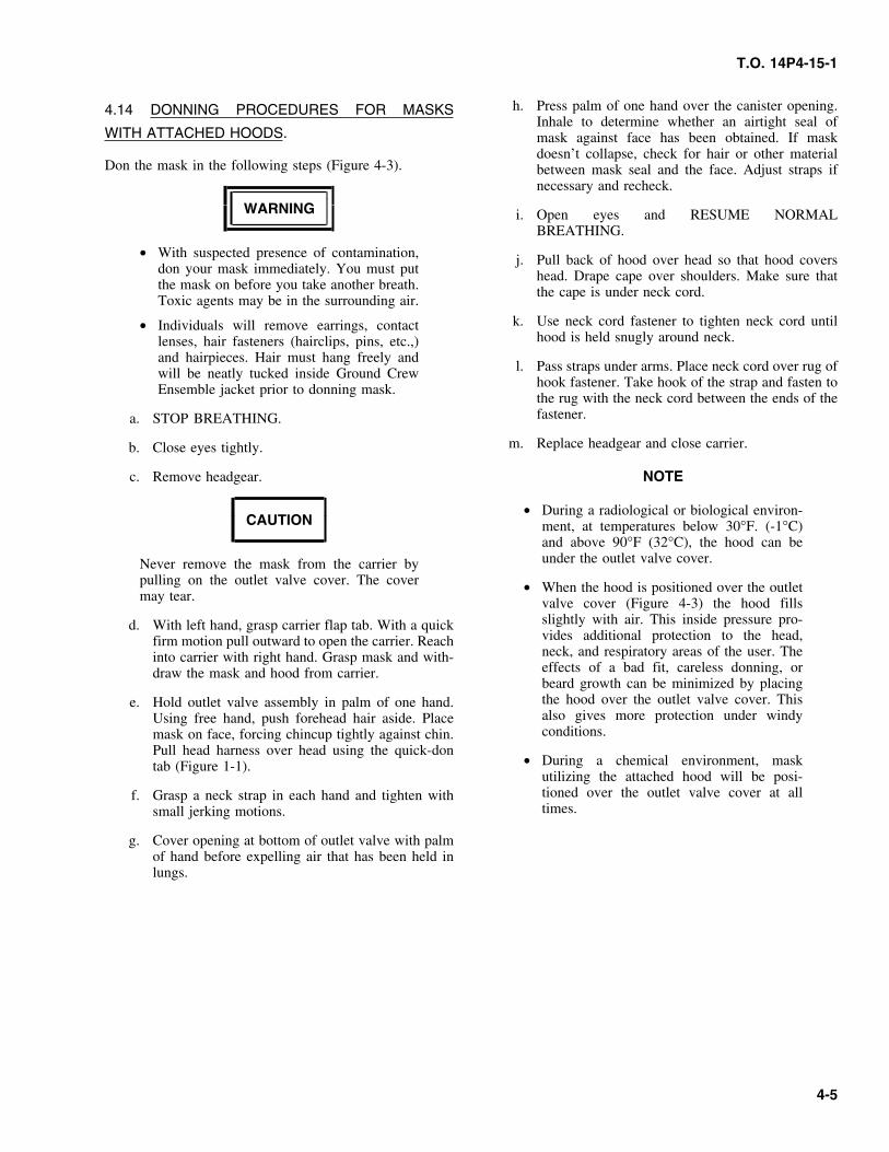
h. Press palm of one hand over the canister opening.4.14 DONNING PROCEDURES FOR MASKSInhale to determine whether an airtight seal of
WITH ATTACHED HOODS. mask against face has been obtained. If maskdoesn’t collapse, check for hair or other material
Don the mask in the following steps (Figure 4-3). between mask seal and the face. Adjust straps ifnecessary and recheck.
WARNING i. Open eyes and RESUME NORMALBREATHING.
• With suspected presence of contamination, j. Pull back of hood over head so that hood coversdon your mask immediately. You must put head. Drape cape over shoulders. Make sure thatthe mask on before you take another breath. the cape is under neck cord.Toxic agents may be in the surrounding air.
k. Use neck cord fastener to tighten neck cord until• Individuals will remove earrings, contacthood is held snugly around neck.lenses, hair fasteners (hairclips, pins, etc.,)
and hairpieces. Hair must hang freely andl. Pass straps under arms. Place neck cord over rug ofwill be neatly tucked inside Ground Crew
hook fastener. Take hook of the strap and fasten toEnsemble jacket prior to donning mask.the rug with the neck cord between the ends of thefastener.a. STOP BREATHING.
m. Replace headgear and close carrier.b. Close eyes tightly.
c. Remove headgear. NOTE
• During a radiological or biological environ-CAUTION ment, at temperatures below 30°F. (-1°C)
and above 90°F (32°C), the hood can beunder the outlet valve cover.Never remove the mask from the carrier by
pulling on the outlet valve cover. The cover • When the hood is positioned over the outletmay tear. valve cover (Figure 4-3) the hood fills
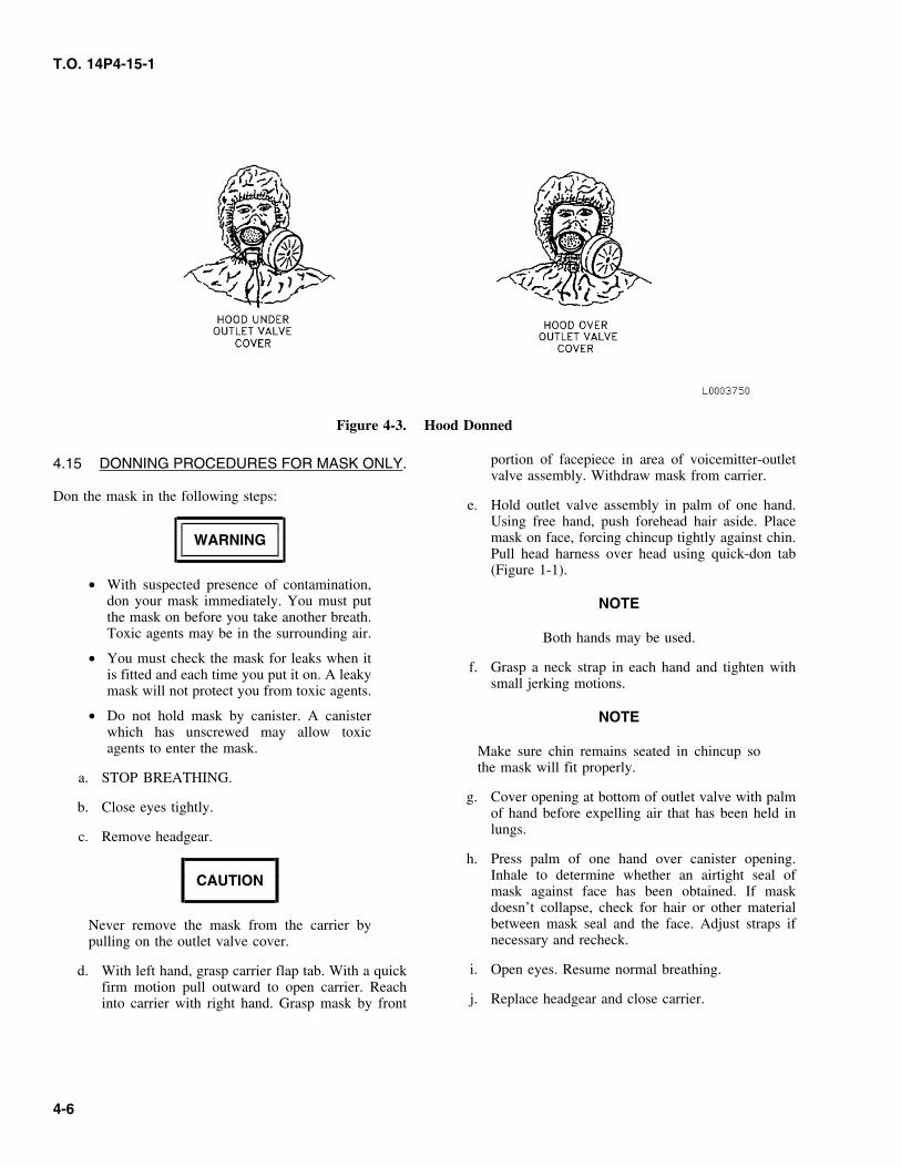
slightly with air. This inside pressure pro-d. With left hand, grasp carrier flap tab. With a quickvides additional protection to the head,firm motion pull outward to open the carrier. Reachneck, and respiratory areas of the user. Theinto carrier with right hand. Grasp mask and with-effects of a bad fit, careless donning, ordraw the mask and hood from carrier.beard growth can be minimized by placingthe hood over the outlet valve cover. Thise. Hold outlet valve assembly in palm of one hand.also gives more protection under windyUsing free hand, push forehead hair aside. Placeconditions.mask on face, forcing chincup tightly against chin.
Pull head harness over head using the quick-don• During a chemical environment, masktab (Figure 1-1).
utilizing the attached hood will be posi-tioned over the outlet valve cover at allf. Grasp a neck strap in each hand and tighten withtimes.small jerking motions.
g. Cover opening at bottom of outlet valve with palmof hand before expelling air that has been held inlungs.
4-5
T.O. 14P4-15-1
Figure 4-3. Hood Donned
portion of facepiece in area of voicemitter-outlet4.15 DONNING PROCEDURES FOR MASK ONLY.valve assembly. Withdraw mask from carrier.
Don the mask in the following steps:e. Hold outlet valve assembly in palm of one hand.
Using free hand, push forehead hair aside. Placemask on face, forcing chincup tightly against chin.WARNINGPull head harness over head using quick-don tab(Figure 1-1).
• With suspected presence of contamination,don your mask immediately. You must put NOTEthe mask on before you take another breath.Toxic agents may be in the surrounding air. Both hands may be used.
• You must check the mask for leaks when itf. Grasp a neck strap in each hand and tighten withis fitted and each time you put it on. A leaky
small jerking motions.mask will not protect you from toxic agents.
• Do not hold mask by canister. A canister NOTEwhich has unscrewed may allow toxicagents to enter the mask. Make sure chin remains seated in chincup so
the mask will fit properly.a. STOP BREATHING.
g. Cover opening at bottom of outlet valve with palmb. Close eyes tightly. of hand before expelling air that has been held in
lungs.c. Remove headgear.
h. Press palm of one hand over canister opening.Inhale to determine whether an airtight seal ofCAUTIONmask against face has been obtained. If maskdoesn’t collapse, check for hair or other materialbetween mask seal and the face. Adjust straps ifNever remove the mask from the carrier bynecessary and recheck.pulling on the outlet valve cover.
i. Open eyes. Resume normal breathing.d. With left hand, grasp carrier flap tab. With a quickfirm motion pull outward to open carrier. Reach
j. Replace headgear and close carrier.into carrier with right hand. Grasp mask by front
4-6
T.O. 14P4-15-1
h. Stow mask and hood in carrier.4.16 DOFFING PROCEDURES.
4.18 DOFFING PROCEDURES FOR MASK ONLY.Separate doffing procedures are included in the followingparagraphs for:
WARNINGa. Masks with attached hoods (Hoods having neckcord, underarm straps and temple tab straps).
Failure to loosen the bottom straps on the maskb. Mask only.prior to removing the mask will place excessive
c. Mask with Joint Service Lightweight Integrated and undue stress on the outlet valve assembly.Suit Technology (JSLIST) Overgarment. Follow This stress on the outlet valve assembly willprocedures in T.O. 14P3-1-141. Follow the appli- contribute to disbonding of the mask.cable procedure for your type.
a. Loosen mask neck straps by rotating buckles for-ward. Grasp mask by outlet valve body and remove
WARNING by pulling down, outward, and up.
b. Reverse head harness over mask facepiece lens andDoffing procedures for contaminated equip- shake or wipe any moisture from inside mask.ment is covered in AFMAN 32-4005.
c. Stow mask in carrier.4.17 DOFFING PROCEDURES FOR MASKS WITH
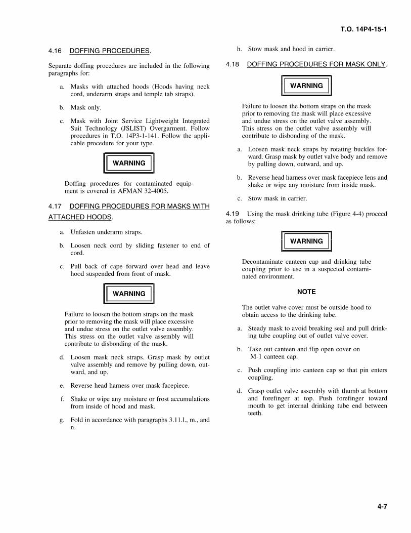
4.19 Using the mask drinking tube (Figure 4-4) proceedATTACHED HOODS.as follows:
a. Unfasten underarm straps.
WARNINGb. Loosen neck cord by sliding fastener to end of
cord.Decontaminate canteen cap and drinking tube
c. Pull back of cape forward over head and leave coupling prior to use in a suspected contami-hood suspended from front of mask. nated environment.
NOTEWARNING
The outlet valve cover must be outside hood toFailure to loosen the bottom straps on the mask obtain access to the drinking tube.prior to removing the mask will place excessive
a. Steady mask to avoid breaking seal and pull drink-and undue stress on the outlet valve assembly.ing tube coupling out of outlet valve cover.This stress on the outlet valve assembly will
contribute to disbonding of the mask.b. Take out canteen and flip open cover on
M-1 canteen cap.d. Loosen mask neck straps. Grasp mask by outletvalve assembly and remove by pulling down, out-
c. Push coupling into canteen cap so that pin entersward, and up.coupling.
e. Reverse head harness over mask facepiece.d. Grasp outlet valve assembly with thumb at bottom
and forefinger at top. Push forefinger towardf. Shake or wipe any moisture or frost accumulationsmouth to get internal drinking tube end betweenfrom inside of hood and mask.teeth.
g. Fold in accordance with paragraphs 3.11.l., m., andn.
4-7
T.O. 14P4-15-1
h. Flip down cover on canteen cap and stow canteen.
i. Return hood to original position (if required).
4.20 To use the mask waterproofing bag (Figure 4-5)proceed as follows:
WARNING
Do not store food in the waterproofing bag.Possible toxic effects may result.
CAUTION
Do not store your mask in the waterproofingbag for more than 24 hours. Moisture and off-gasing buildup in the bag may damage thecanister.
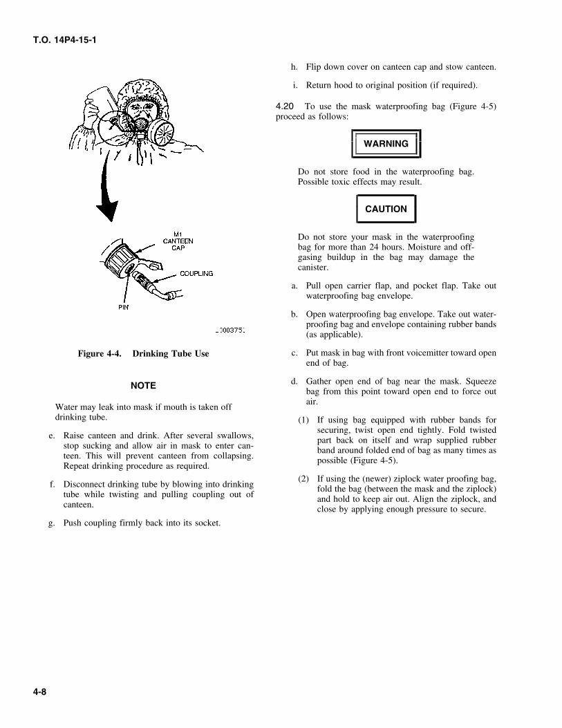
a. Pull open carrier flap, and pocket flap. Take outwaterproofing bag envelope.
b. Open waterproofing bag envelope. Take out water-proofing bag and envelope containing rubber bands(as applicable).
c. Put mask in bag with front voicemitter toward openFigure 4-4. Drinking Tube Useend of bag.
d. Gather open end of bag near the mask. SqueezeNOTEbag from this point toward open end to force outair.
Water may leak into mask if mouth is taken offdrinking tube. (1) If using bag equipped with rubber bands for
securing, twist open end tightly. Fold twistede. Raise canteen and drink. After several swallows, part back on itself and wrap supplied rubber
stop sucking and allow air in mask to enter can- band around folded end of bag as many times asteen. This will prevent canteen from collapsing. possible (Figure 4-5).Repeat drinking procedure as required.
(2) If using the (newer) ziplock water proofing bag,f. Disconnect drinking tube by blowing into drinking fold the bag (between the mask and the ziplock)
tube while twisting and pulling coupling out of and hold to keep air out. Align the ziplock, andcanteen. close by applying enough pressure to secure.
g. Push coupling firmly back into its socket.
4-8
T.O. 14P4-15-1
Figure 4-5. Waterproofing Bag Use
e. Put bag in carrier with fold toward front of carrier. 4.22 Cold Weather Operation. General instructions thatmust be followed in cold weather include the following:
f. Close carrier flap.
a. Before entering a warm area from freezing temper-4.21 When use of the waterproofing bag is no longer atures, remove frost and snow from mask.required proceed as follows:
b. Dry mask with a clean cloth, in a warm indoora. Pull open carrier flap and pull out bag. area. Carefully dry outlet and nosecup valves.
b. Remove mask from bag. 4.23 Follow the usual procedures when donning orwearing the mask in cold weather, but keep in mind thec. Fold bag neatly. Place bag and rubber band(s) (asfollowing points:applicable) in waterproofing bag envelope.
a. Do not breathe out forcefully or the eyelens willd. Put waterproofing bag envelope in carrier pocketsteam up.and close flap.
4-9
T.O. 14P4-15-1
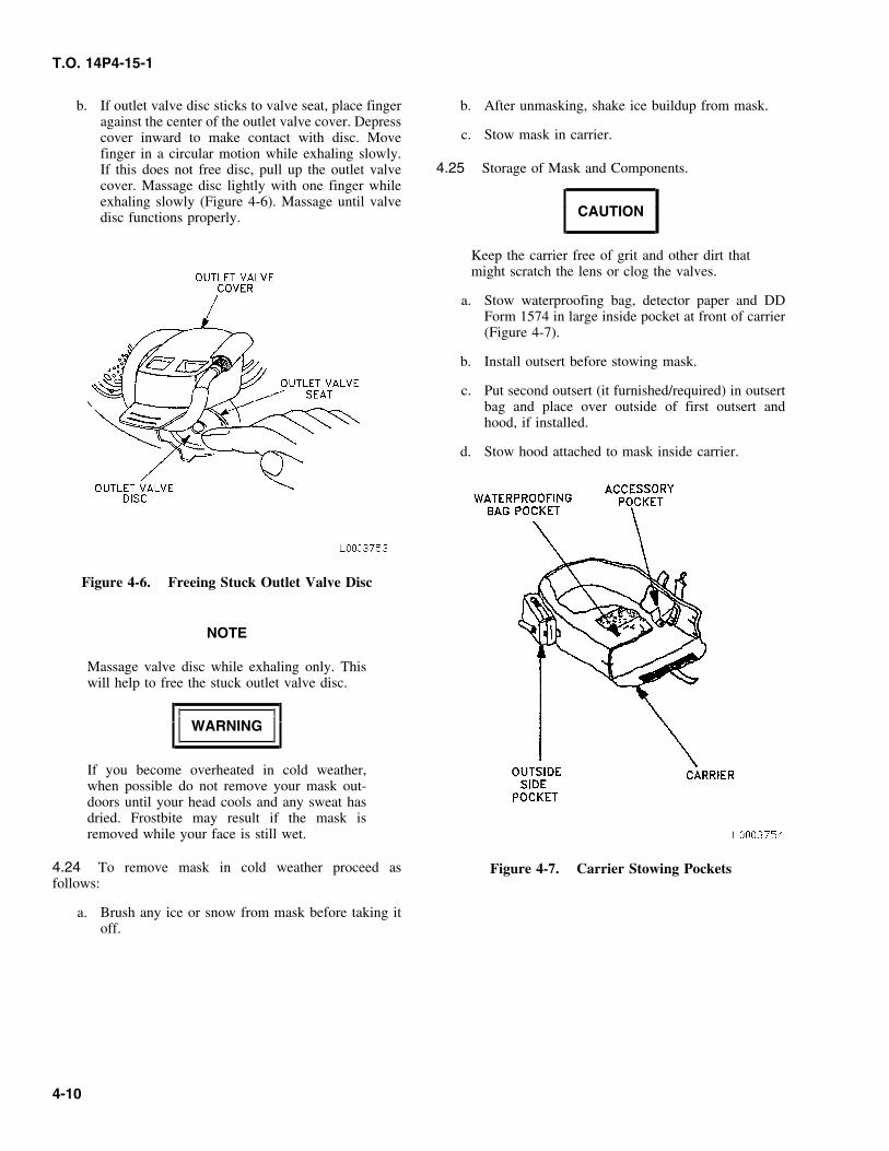
b. If outlet valve disc sticks to valve seat, place finger b. After unmasking, shake ice buildup from mask.against the center of the outlet valve cover. Depress
c. Stow mask in carrier.cover inward to make contact with disc. Movefinger in a circular motion while exhaling slowly.
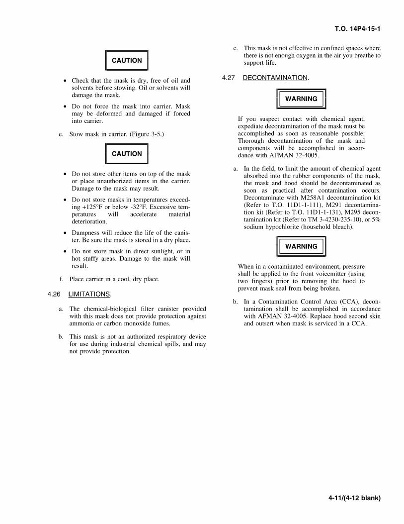
4.25 Storage of Mask and Components.If this does not free disc, pull up the outlet valvecover. Massage disc lightly with one finger whileexhaling slowly (Figure 4-6). Massage until valve
CAUTIONdisc functions properly.
Keep the carrier free of grit and other dirt thatmight scratch the lens or clog the valves.
a. Stow waterproofing bag, detector paper and DDForm 1574 in large inside pocket at front of carrier(Figure 4-7).
b. Install outsert before stowing mask.
c. Put second outsert (it furnished/required) in outsertbag and place over outside of first outsert andhood, if installed.
d. Stow hood attached to mask inside carrier.
Figure 4-6. Freeing Stuck Outlet Valve Disc
NOTE
Massage valve disc while exhaling only. Thiswill help to free the stuck outlet valve disc.
WARNING
If you become overheated in cold weather,when possible do not remove your mask out-doors until your head cools and any sweat hasdried. Frostbite may result if the mask isremoved while your face is still wet.
4.24 To remove mask in cold weather proceed as Figure 4-7. Carrier Stowing Pocketsfollows:
a. Brush any ice or snow from mask before taking itoff.
4-10
T.O. 14P4-15-1
c. This mask is not effective in confined spaces wherethere is not enough oxygen in the air you breathe to
CAUTION support life.
4.27 DECONTAMINATION.• Check that the mask is dry, free of oil andsolvents before stowing. Oil or solvents willdamage the mask.
WARNING• Do not force the mask into carrier. Mask
may be deformed and damaged if forcedIf you suspect contact with chemical agent,into carrier.expediate decontamination of the mask must beaccomplished as soon as reasonable possible.e. Stow mask in carrier. (Figure 3-5.)Thorough decontamination of the mask andcomponents will be accomplished in accor-
CAUTION dance with AFMAN 32-4005.
a. In the field, to limit the amount of chemical agent• Do not store other items on top of the mask absorbed into the rubber components of the mask,
or place unauthorized items in the carrier. the mask and hood should be decontaminated asDamage to the mask may result. soon as practical after contamination occurs.
Decontaminate with M258A1 decontamination kit• Do not store masks in temperatures exceed-(Refer to T.O. 11D1-1-111), M291 decontamina-ing +125°F or below -32°F. Excessive tem-tion kit (Refer to T.O. 11D1-1-131), M295 decon-peratures will accelerate materialtamination kit (Refer to TM 3-4230-235-10), or 5%deterioration.sodium hypochlorite (household bleach).
• Dampness will reduce the life of the canis-ter. Be sure the mask is stored in a dry place.
WARNING• Do not store mask in direct sunlight, or in
hot stuffy areas. Damage to the mask willresult. When in a contaminated environment, pressure
shall be applied to the front voicemitter (usingf. Place carrier in a cool, dry place. two fingers) prior to removing the hood to
prevent mask seal from being broken.4.26 LIMITATIONS.
b. In a Contamination Control Area (CCA), decon-a. The chemical-biological filter canister provided tamination shall be accomplished in accordance
with this mask does not provide protection against with AFMAN 32-4005. Replace hood second skinammonia or carbon monoxide fumes. and outsert when mask is serviced in a CCA.
b. This mask is not an authorized respiratory devicefor use during industrial chemical spills, and maynot provide protection.
4-11/(4-12 blank)

T.O. 14P4-15-1
CHAPTER 5MAINTENANCE INSTRUCTIONS
(3) Before long term storage (30 days or more)5.1 OPERATIONAL CHECKOUT.
(4) Prior to turn-in to supply.NOTE
(5) After completion of each trainingMasks that have never been issued and are still contingency/exercise.packaged in unopened original container, do
c. Mask in bulk storage prior to issue will be main-not require an inspection.tained and inspected as follows:
Once the MCU-2 Series mask is issued, all maintenance(1) Mask in original manufacture packaging do notbecomes the responsibility of the user. This chapter details
require cleaning or inspection.procedures for use during maintenance.
(2) Mask that have been removed from original5.2 INSPECTION AND PREVENTIVEmanufacture packaging will be cleaned and
MAINTENANCE. inspected every six months by the possessingunit.
a. This chapter contains the procedures and instruc-d. These inspections shall be documented on a DDtions necessary to perform preventive maintenance
Form 1574 or Data Automated System (DAS). Thechecks and services. Table 5-1 provides a list ofinspection document shall contain at least the fol-items to be checked, inspection procedures, and alowing information:corrective action or a referral to the Repair and
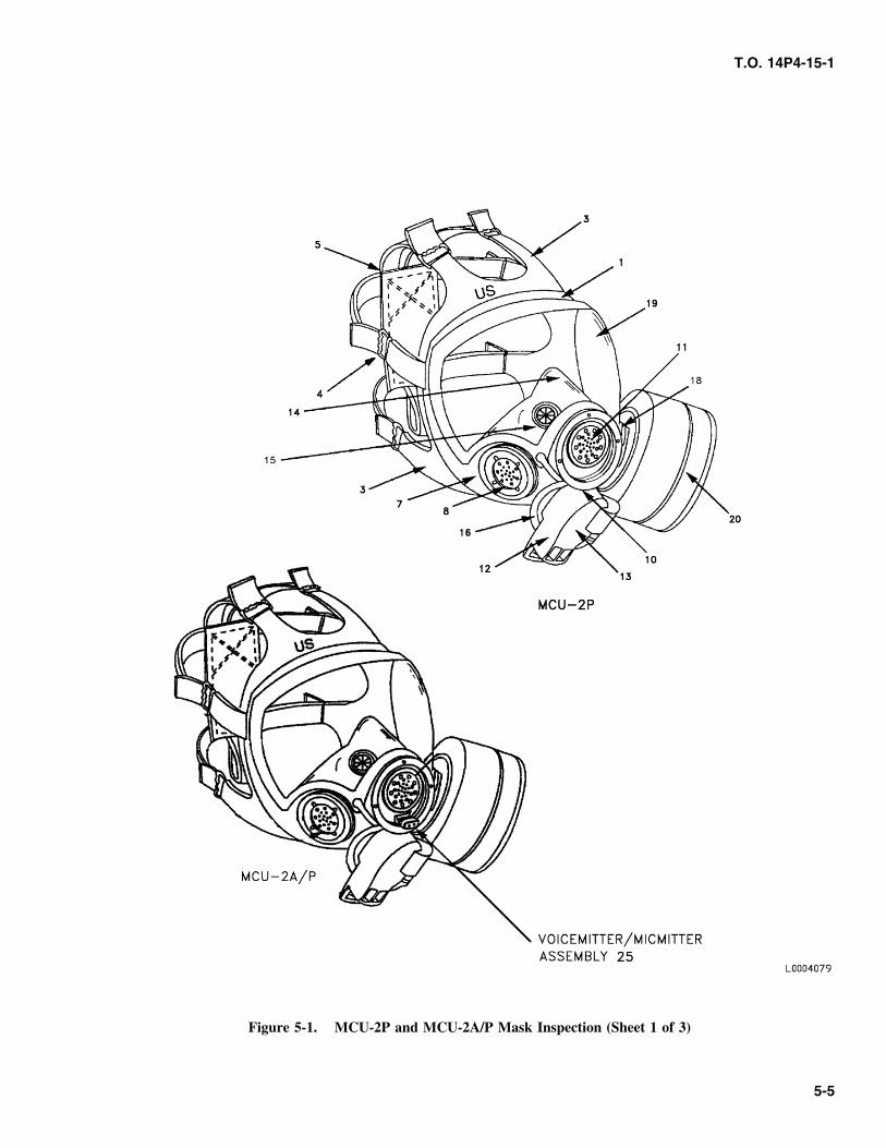
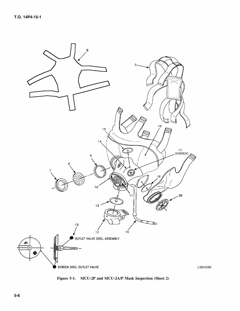
Replacement chapter of this manual. Refer to(1) Federal stock number of the mask, type, andFigure 5-1 while using this table. Numbers in
size. Mask lot number, functional address ofparentheses () in Table 5-1, refer to the similarinspecting activity, signature of inspector, datenumbered items on Figure 5-1 (3 sheets).inspected, and date next inspection is due.
b. Masks will be cleaned and inspected by the(2) Inspection document can be used to annotateindividual:
recurring inspections.(1) Upon issue and every six months after initial
(3) When a serviceable C2 series canister isissue date during peacetime.installed, date installed and canister lot numberwill be annotated in remarks section of DD(2) Prior to deployment and every seven days dur-Form 1574.ing contingency operations.
Table 5-1. Inspection and Preventive Maintenance Checks
ITEM INSPECT FOR CORRECTIVE ACTIONNOTE
•Take off outsert before inspecting mask.
•All personnel must clean mask in accordance with para-graph 5.5 (CLEANING) before inspection of mask.
Facepiece Cracks, tears, or deterioration and separation between sili- Condemn Mask.(1) cone, rubber, and the metal parts.
Faceseal Cracks or tears. Run finger over seal to inspect for nicks Condemn Mask.(Not Shown) or surface irregularities. Faceseal must be soft, smooth,(2) and pliable.
Forehead, Nicks or rips, along edges, or where buckles connect. Condemn Mask.Temple, and Run a finger around edges to check for discrepancies.Neck Tabs(3)
5-1
T.O. 14P4-15-1
Table 5-1. Inspection and Preventive Maintenance Checks - Continued
ITEM INSPECT FOR CORRECTIVE ACTIONBuckles Bends, cracks or looseness where molded into the Condemn Mask.(4) facepiece tabs. Pull on head harness straps. Make sure the
buckles hold the strap tight.
Head Tears, surface dirt, or mildew. Pull straps to make sure Replace if straps are torn,Harness they have not lost their elasticity. broken, or have lost their(5) elasticity. Refer to para-
graph 5.8.
Clean off surface dirt ormildew with a stiff bristlebrush.
Skull Cap Same as for item 5. Same as for item 5.(6)
Side Corrosion or looseness. Replace if corroded. Tight-Voicemitter en if loose. Refer to para-Retaining graph 5.9.Ring(7)
Side Dents, punctures, or cracks. The four pins in the center Replace if dented, punc-Voicemitter face toward the outside of mask. tured, or cracked. Remove(8) and correctly reinstall if
four pins are not facingoutwards.
Side Voicemitter Cracks and cuts. Install a new sideGasket voicemitter gasket, if UN-(9) SERVICEABLE, (e.g. cut,
distorted or damaged). Re-fer to paragraph 5.9.a.
WARNING
Do not attempt in any way to loosen front voicemitterring during check for tightness.
Front Tightness using the tips of two fingers on the flat part of Repair mask in accordanceVoicemitter the ring (See Figure 5-11). with paragraph 5.17.RetainingRing(10)
Front Punctures or cracks. (Damaged microphone connector as- Repair mask in accordanceVoicemitter sembly MCU-2A/P). with paragraph 5.17.(11)
Outlet Valve Cracks, rips and general cleanliness inside and out. Replace if cracked, rippedCover or if it will not seat firmly(12) on outlet valve body. Refer
to paragraph 5.10.
Wipe away any dirt ormoisture on cover with asoft, dry, clean cloth.
5-2
T.O. 14P4-15-1
Table 5-1. Inspection and Preventive Maintenance Checks - Continued
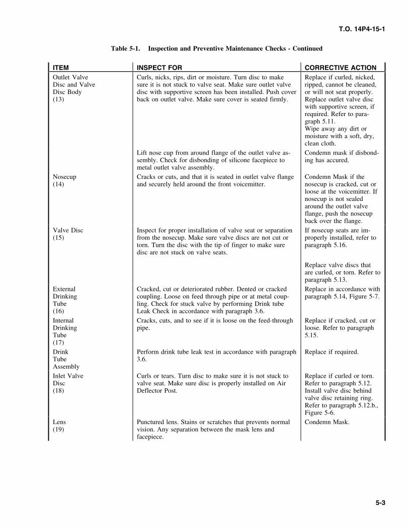
ITEM INSPECT FOR CORRECTIVE ACTIONOutlet Valve Curls, nicks, rips, dirt or moisture. Turn disc to make Replace if curled, nicked,Disc and Valve sure it is not stuck to valve seat. Make sure outlet valve ripped, cannot be cleaned,Disc Body disc with supportive screen has been installed. Push cover or will not seat properly.(13) back on outlet valve. Make sure cover is seated firmly. Replace outlet valve disc
with supportive screen, ifrequired. Refer to para-graph 5.11.Wipe away any dirt ormoisture with a soft, dry,clean cloth.
Lift nose cup from around flange of the outlet valve as- Condemn mask if disbond-sembly. Check for disbonding of silicone facepiece to ing has accured.metal outlet valve assembly.
Nosecup Cracks or cuts, and that it is seated in outlet valve flange Condemn Mask if the(14) and securely held around the front voicemitter. nosecup is cracked, cut or
loose at the voicemitter. Ifnosecup is not sealedaround the outlet valveflange, push the nosecupback over the flange.
Valve Disc Inspect for proper installation of valve seat or separation If nosecup seats are im-(15) from the nosecup. Make sure valve discs are not cut or properly installed, refer to
torn. Turn the disc with the tip of finger to make sure paragraph 5.16.disc are not stuck on valve seats.
Replace valve discs thatare curled, or torn. Refer toparagraph 5.13.
External Cracked, cut or deteriorated rubber. Dented or cracked Replace in accordance withDrinking coupling. Loose on feed through pipe or at metal coup- paragraph 5.14, Figure 5-7.Tube ling. Check for stuck valve by performing Drink tube(16) Leak Check in accordance with paragraph 3.6.
Internal Cracks, cuts, and to see if it is loose on the feed-through Replace if cracked, cut orDrinking pipe. loose. Refer to paragraphTube 5.15.(17)
Drink Perform drink tube leak test in accordance with paragraph Replace if required.Tube 3.6.Assembly
Inlet Valve Curls or tears. Turn disc to make sure it is not stuck to Replace if curled or torn.Disc valve seat. Make sure disc is properly installed on Air Refer to paragraph 5.12.(18) Deflector Post. Install valve disc behind
valve disc retaining ring.Refer to paragraph 5.12.b.,Figure 5-6.
Lens Punctured lens. Stains or scratches that prevents normal Condemn Mask.(19) vision. Any separation between the mask lens and
facepiece.
5-3
T.O. 14P4-15-1
Table 5-1. Inspection and Preventive Maintenance Checks - Continued
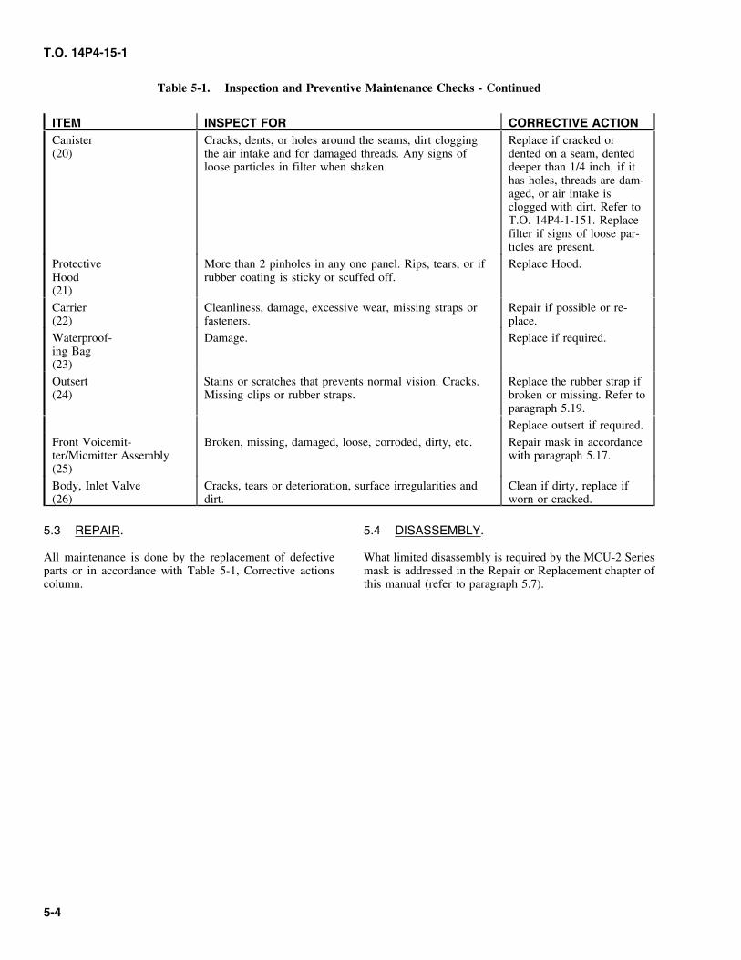
ITEM INSPECT FOR CORRECTIVE ACTIONCanister Cracks, dents, or holes around the seams, dirt clogging Replace if cracked or(20) the air intake and for damaged threads. Any signs of dented on a seam, dented
loose particles in filter when shaken. deeper than 1/4 inch, if ithas holes, threads are dam-aged, or air intake isclogged with dirt. Refer toT.O. 14P4-1-151. Replacefilter if signs of loose par-ticles are present.
Protective More than 2 pinholes in any one panel. Rips, tears, or if Replace Hood.Hood rubber coating is sticky or scuffed off.(21)
Carrier Cleanliness, damage, excessive wear, missing straps or Repair if possible or re-(22) fasteners. place.
Waterproof- Damage. Replace if required.ing Bag(23)
Outsert Stains or scratches that prevents normal vision. Cracks. Replace the rubber strap if(24) Missing clips or rubber straps. broken or missing. Refer to
paragraph 5.19.
Replace outsert if required.
Front Voicemit- Broken, missing, damaged, loose, corroded, dirty, etc. Repair mask in accordanceter/Micmitter Assembly with paragraph 5.17.(25)
Body, Inlet Valve Cracks, tears or deterioration, surface irregularities and Clean if dirty, replace if(26) dirt. worn or cracked.
5.3 REPAIR. 5.4 DISASSEMBLY.
All maintenance is done by the replacement of defective What limited disassembly is required by the MCU-2 Seriesparts or in accordance with Table 5-1, Corrective actions mask is addressed in the Repair or Replacement chapter ofcolumn. this manual (refer to paragraph 5.7).
5-4
T.O. 14P4-15-1
Figure 5-1. MCU-2P and MCU-2A/P Mask Inspection (Sheet 1 of 3)
5-5
T.O. 14P4-15-1
Figure 5-1. MCU-2P and MCU-2A/P Mask Inspection (Sheet 2)
5-6
T.O. 14P4-15-1
Figure 5-1. MCU-2P and MCU-2A/P Mask Inspection (Sheet 3)
5-7
T.O. 14P4-15-1
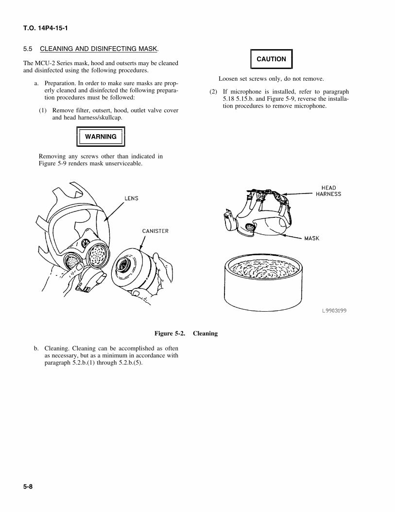
5.5 CLEANING AND DISINFECTING MASK.
CAUTIONThe MCU-2 Series mask, hood and outserts may be cleanedand disinfected using the following procedures.
Loosen set screws only, do not remove.a. Preparation. In order to make sure masks are prop-
erly cleaned and disinfected the following prepara- (2) If microphone is installed, refer to paragraphtion procedures must be followed: 5.18 5.15.b. and Figure 5-9, reverse the installa-
tion procedures to remove microphone.(1) Remove filter, outsert, hood, outlet valve cover
and head harness/skullcap.
WARNING
Removing any screws other than indicated inFigure 5-9 renders mask unserviceable.
Figure 5-2. Cleaning
b. Cleaning. Cleaning can be accomplished as oftenas necessary, but as a minimum in accordance withparagraph 5.2.b.(1) through 5.2.b.(5).
5-8
T.O. 14P4-15-1
NOTECAUTION
Disinfecting solution and rinse water must bereplaced after approximately 20 masks have• Alcohol based towelettes (or equivalent)been disinfected or more often if needed.may be used for expedient disinfectant of
the mask (with the exception of the lens)(2) Immerse mask in disinfecting solution. Soakusing a non-scrubbing motion. Take care not
and swirl in disinfecting solution for 5 minutes.to remove/damage lot number on neck tab.
(3) Rinse mask twice in clean potable water and• Do not let the canister get wet.swirl 2 to 3 minutes.
• Do not place mask in water with tempera-tures exceeding 110°F. (4) Utilizing canteen, disinfect drink tube assembly
as follows:• Do not dry-wipe lens.
(a) Fill canteen with disinfecting solution. CapNOTE and shake canteen.
To clean the mask use warm potable water (b) Push external drink tube coupling into can-(NMT 110°F) and a mild liquid detergent that teen cap making sure it is seated completely.does not contain Lanolin, oils, perfumes or
(c) Turn up canteen, squeeze sides of canteenabrasives.forcing the solution through the drink tube
(1) Immerse mask and components (outserts, outlet until canteen is empty.valve cover, and hood) in mild liquid detergent
(d) Remove canteen from mask.and warm potable water solution. Agitatearound in solution.
(e) Rinse canteen with clean potable water twice.(2) Lift nosecup up and remove from around flange
(f) Fill canteen with clear potable water, repeatof outlet valve assembly to facilitate and thor-steps (b), (c) and (d).ough cleaning between nosecup and facepiece.
(g) Dry mask and components with lint free(3) Clean outlet valve assembly and under outletcloth.valve disc.
(h) When mask is completely dry reassemble(4) Wash mask and components with soft wet clothmask and all components.to remove any hazing or dirt from mask.
NOTE(5) Use clear warm potable water to rinse all partsby agitating the mask and components quicklyto remove all detergent. Multiple mask (optional). To clean large quan-
tities of individual masks, you must use thec. Disinfecting. Disinfecting can be accomplished as newer production model M1 (See Figure 5-10)
often as necessary, but as a minimum upon issue, canteen cap (NSN 8465-00-930-2077, which ischange of user and prior to turn-in. equipped with a funnel shaped extension at the
bottom). The cap can be adapted with a 3/16-NOTE inch outside diameter (O.D.) brass tube. This
brass tube is fitted into a piece of rubber orDisinfecting solution is made by mixing 1 oz. plastic tubing (length as determined by user)(30 milliliters) household bleach per 2 gallons and then fitted on the opposite end with any(7.5L) water. Quantity of disinfecting solution number of fittings (e.g. standard automative)required is variable depending on size of that would allow connection to a pressurecontainer used to allow complete immersion of container (e.g. plant sprayer). After attachingmask into solution. the external drink tube coupling of the mask to
be sanitized, attach a suitable overflow tube to(1) Mask must prepared and cleaned in accordance
with paragraph 5.5.a. and 5.5.b.
5-9
T.O. 14P4-15-1
the internal drink tube, then place the opposite (1) Position new harness/skullcap in facepiece withend in a suitable overflow receptacle. Pressur- straps next to correct buckles.ize the container, then open the valve on the
(2) Push tips into buckles at an angle. Work strapspressure container, forcing the solution throughthrough buckles about one inch.the drink tube system and into a suitable recep-
tacle. When finished, thoroughly flush the(3) Stretch each harness/skullcap strap away fromcontainer with clean water. Now flush clean
facepiece. Check that buckles hold straps tight.water through he drink system as describedabove (See Figure 5-1).
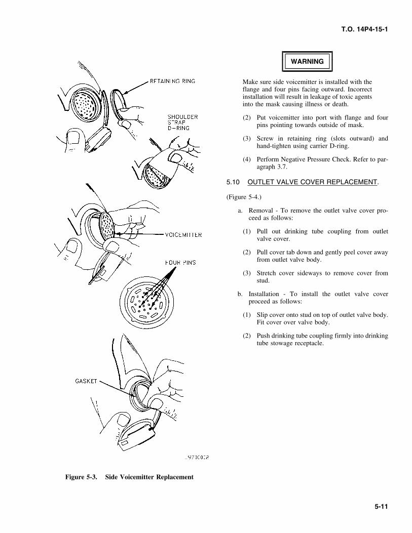
5.9 SIDE VOICEMITTER REPLACEMENT.
5.6 To clean the carrier, brush any dirt or grit from(Figure 5-3).carrier using a brush dipped in clean cool water.
a. Removal - To remove the side voicemitter proceed5.7 REPAIR OR REPLACEMENT. as follows:
Maintenance actions in this chapter are limited to replace- (1) Using the straight side of carrier shoulder strapment of defective mask parts. Only those parts that may be D-ring, unscrew and take out voicemitter retain-replaced are addressed. Defective parts other than those ing ring.listed are cause for mask condemnation.
(2) Reach inside mask and push out voicemitter.5.8 HEAD HARNESS/SKULL CAP
(3) Remove gasket.REPLACEMENT.
b. Installation - To install the side voicemitter proceeda. Removal - To remove the head harness/skull cap as follows:
work straps out of buckles. Take out tips at anangle.
WARNINGb. Installation - To install the head harness/skull cap
harness proceed as follows:The side voicemitter must be installed using aserviceable gasket. Use of an UNSERVICE-NOTEABLE gasket could result in leakage of toxicagents causing illness or death.The elastic webbing on head harness that joins
the two forehead straps should be positioned at (1) Place serviceable (not damaged, e.g. Cut, Torn,the top of the facepiece and on the outside of etc.) gasket into port on facepiece and gentlythe harness. Seams on skullcap should be posi- press into place.tioned to the outside.
5-10
T.O. 14P4-15-1
WARNING
Make sure side voicemitter is installed with theflange and four pins facing outward. Incorrectinstallation will result in leakage of toxic agentsinto the mask causing illness or death.
(2) Put voicemitter into port with flange and fourpins pointing towards outside of mask.
(3) Screw in retaining ring (slots outward) andhand-tighten using carrier D-ring.
(4) Perform Negative Pressure Check. Refer to par-agraph 3.7.
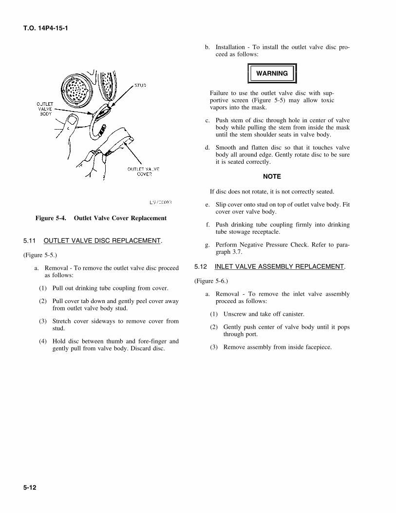
5.10 OUTLET VALVE COVER REPLACEMENT.
(Figure 5-4.)
a. Removal - To remove the outlet valve cover pro-ceed as follows:
(1) Pull out drinking tube coupling from outletvalve cover.
(2) Pull cover tab down and gently peel cover awayfrom outlet valve body.
(3) Stretch cover sideways to remove cover fromstud.
b. Installation - To install the outlet valve coverproceed as follows:
(1) Slip cover onto stud on top of outlet valve body.Fit cover over valve body.
(2) Push drinking tube coupling firmly into drinkingtube stowage receptacle.
Figure 5-3. Side Voicemitter Replacement
5-11
T.O. 14P4-15-1
b. Installation - To install the outlet valve disc pro-ceed as follows:
WARNING
Failure to use the outlet valve disc with sup-portive screen (Figure 5-5) may allow toxicvapors into the mask.
c. Push stem of disc through hole in center of valvebody while pulling the stem from inside the maskuntil the stem shoulder seats in valve body.
d. Smooth and flatten disc so that it touches valvebody all around edge. Gently rotate disc to be sureit is seated correctly.
NOTE
If disc does not rotate, it is not correctly seated.
e. Slip cover onto stud on top of outlet valve body. Fitcover over valve body.
Figure 5-4. Outlet Valve Cover Replacementf. Push drinking tube coupling firmly into drinking
tube stowage receptacle.
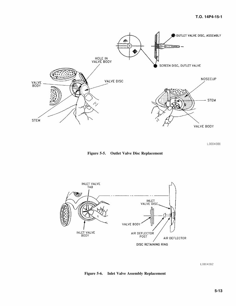
5.11 OUTLET VALVE DISC REPLACEMENT.g. Perform Negative Pressure Check. Refer to para-
graph 3.7.(Figure 5-5.)
5.12 INLET VALVE ASSEMBLY REPLACEMENT.a. Removal - To remove the outlet valve disc proceedas follows:
(Figure 5-6.)(1) Pull out drinking tube coupling from cover.
a. Removal - To remove the inlet valve assembly(2) Pull cover tab down and gently peel cover away proceed as follows:
from outlet valve body stud.(1) Unscrew and take off canister.
(3) Stretch cover sideways to remove cover from(2) Gently push center of valve body until it popsstud.
through port.(4) Hold disc between thumb and fore-finger and
(3) Remove assembly from inside facepiece.gently pull from valve body. Discard disc.
5-12
T.O. 14P4-15-1
Figure 5-5. Outlet Valve Disc Replacement
Figure 5-6. Inlet Valve Assembly Replacement
5-13
T.O. 14P4-15-1
(4) Remove valve body from air deflector post. (4) Smooth disc so that it lies flat. Gently rotate discwith finger to be sure disc does not bind and is
(5) Lift disc off post. Discard disc. seated correctly.
b. Installation - To install the inlet valve assembly 5.14 EXTERNAL DRINKING TUBEproceed as follows:
REPLACEMENT.(1) Push valve body into port. Be sure tabs face
outward and groove in body seats in rim of port. (Figure 5-8.)
(2) Press disc onto post of air deflector assembly a. Removal - To remove the drinking tube proceed asuntil it seats behind disc retaining ring follows:(Figure 5-6).
(1) Unscrew and remove canister.(3) From inside facepiece, push air deflector assem-
(2) Pull out drinking tube coupling from outletbly into valve body while holding valve body invalve cover.port. Head of air deflector post must stick
through hole in center of valve body. Side edges(3) Pull cover tab down and gently peel cover awayof air deflector shall be between the raised
from outlet valve body.parallel guides on inside of facepiece.
(4) Rotate valve body using tabs to verify correctseating.
(5) Screw canister into mask handtight.
(6) Perform negative pressure check. Refer to para-graph 3.7.
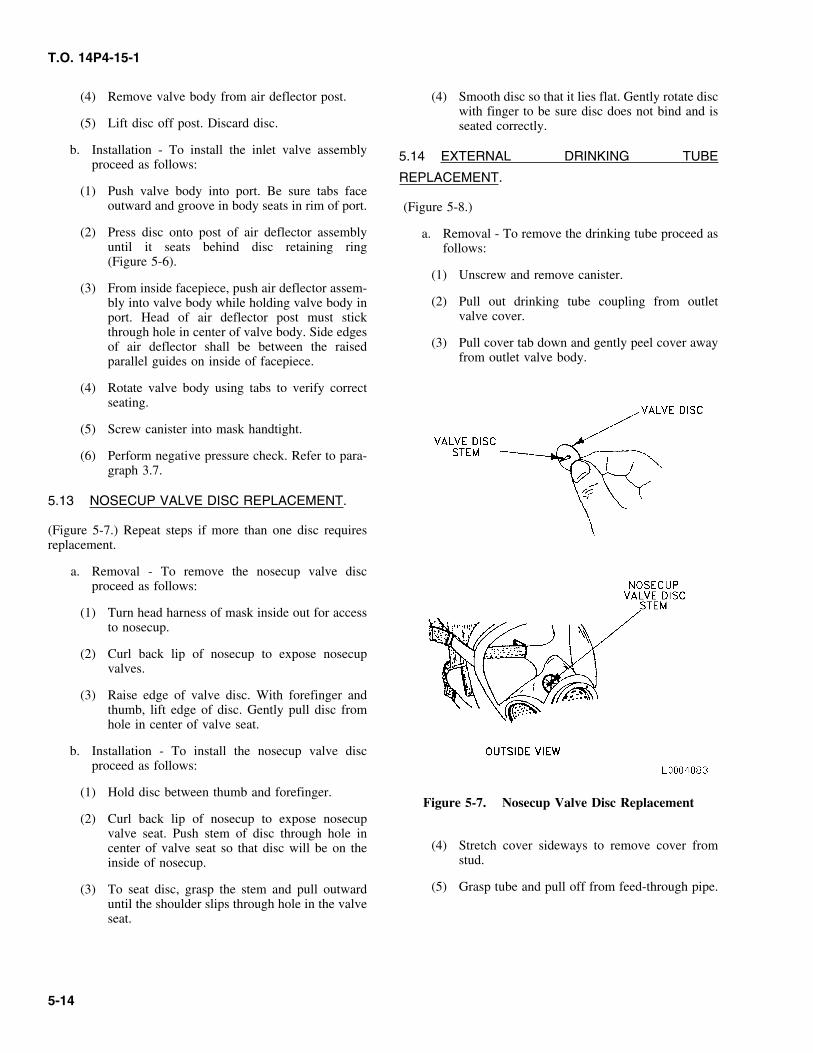
5.13 NOSECUP VALVE DISC REPLACEMENT.
(Figure 5-7.) Repeat steps if more than one disc requiresreplacement.
a. Removal - To remove the nosecup valve discproceed as follows:
(1) Turn head harness of mask inside out for accessto nosecup.
(2) Curl back lip of nosecup to expose nosecupvalves.
(3) Raise edge of valve disc. With forefinger andthumb, lift edge of disc. Gently pull disc fromhole in center of valve seat.
b. Installation - To install the nosecup valve discproceed as follows:
(1) Hold disc between thumb and forefinger.Figure 5-7. Nosecup Valve Disc Replacement
(2) Curl back lip of nosecup to expose nosecupvalve seat. Push stem of disc through hole in
(4) Stretch cover sideways to remove cover fromcenter of valve seat so that disc will be on thestud.inside of nosecup.
(5) Grasp tube and pull off from feed-through pipe.(3) To seat disc, grasp the stem and pull outwarduntil the shoulder slips through hole in the valveseat.
5-14
T.O. 14P4-15-1
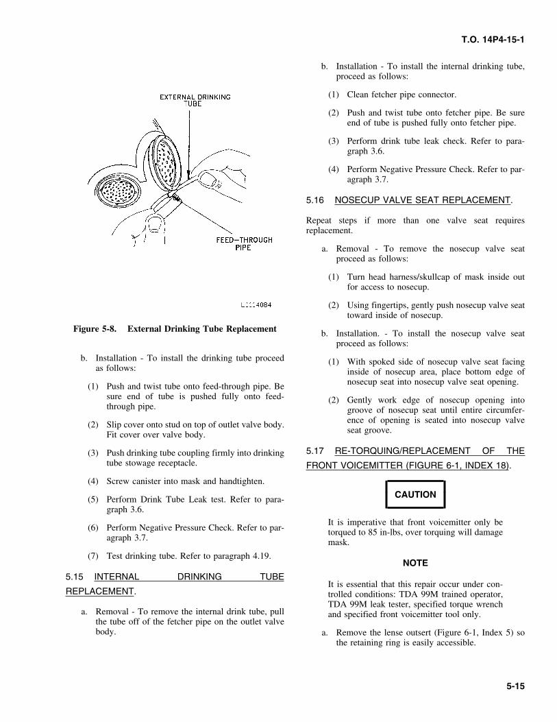
b. Installation - To install the internal drinking tube,proceed as follows:
(1) Clean fetcher pipe connector.
(2) Push and twist tube onto fetcher pipe. Be sureend of tube is pushed fully onto fetcher pipe.
(3) Perform drink tube leak check. Refer to para-graph 3.6.
(4) Perform Negative Pressure Check. Refer to par-agraph 3.7.
5.16 NOSECUP VALVE SEAT REPLACEMENT.
Repeat steps if more than one valve seat requiresreplacement.
a. Removal - To remove the nosecup valve seatproceed as follows:
(1) Turn head harness/skullcap of mask inside outfor access to nosecup.
(2) Using fingertips, gently push nosecup valve seattoward inside of nosecup.
Figure 5-8. External Drinking Tube Replacement b. Installation. - To install the nosecup valve seatproceed as follows:
b. Installation - To install the drinking tube proceed (1) With spoked side of nosecup valve seat facingas follows: inside of nosecup area, place bottom edge of
nosecup seat into nosecup valve seat opening.(1) Push and twist tube onto feed-through pipe. Besure end of tube is pushed fully onto feed- (2) Gently work edge of nosecup opening intothrough pipe. groove of nosecup seat until entire circumfer-
ence of opening is seated into nosecup valve(2) Slip cover onto stud on top of outlet valve body.seat groove.Fit cover over valve body.
5.17 RE-TORQUING/REPLACEMENT OF THE(3) Push drinking tube coupling firmly into drinkingtube stowage receptacle. FRONT VOICEMITTER (FIGURE 6-1, INDEX 18).
(4) Screw canister into mask and handtighten.
CAUTION(5) Perform Drink Tube Leak test. Refer to para-graph 3.6.
It is imperative that front voicemitter only be(6) Perform Negative Pressure Check. Refer to par- torqued to 85 in-lbs, over torquing will damage
agraph 3.7. mask.
(7) Test drinking tube. Refer to paragraph 4.19.NOTE
5.15 INTERNAL DRINKING TUBEIt is essential that this repair occur under con-
REPLACEMENT. trolled conditions: TDA 99M trained operator,TDA 99M leak tester, specified torque wrench
a. Removal - To remove the internal drink tube, pull and specified front voicemitter tool only.the tube off of the fetcher pipe on the outlet valvebody. a. Remove the lense outsert (Figure 6-1, Index 5) so
the retaining ring is easily accessible.
5-15
T.O. 14P4-15-1
b. Using the specified tool, loosen the retaining ring another condemned mask, or replace with a newby inserting the four pins on the tool into the four front voicemitter with retaining ring (part No.holes in the retaining ring. 88115035-2) and repeat steps b. through h.
above.c. Remove front voicemitter from mask by turning in
the counter clockwise direction. Pay close attention (2) If the mask fails the second leakage test andto the position of the micmitter and the indentation reason for failure can not be determined, itmade by the micmitter. (MCU-2A/P ONLY). should be disposed of in accordance with distri-
bution instructions provided by the Itemd. Clean rubber seal (this seal is not removable) and Manager.
front voicemitter to include the threaded housing inaccordance with paragraph 5.5. 5.18 M101/A1C OR SIMILAR TYPE MICROPHONE
INSTALLATION.e. Reinstall voicemitter
(1) Hand tighten initially by turning in the clock- a. Installation - To install the microphone proceed aswise direction. Make sure the micmitter (MCU- follows:2A/P ONLY) is at the 5:30 position so that it
(1) Place mask on a flat surface, with head harnesswill end up being at the six O’clock position orfacing toward you.lined up with the same indentation made by the
voicemitter during initial torquing.(2) Position head harness so you can easily work on
the inside area of mask.(2) Mount mask on the TDA 99M head form, usingthe specified torque wrench and specified front
(3) Find and examine microphone connector assem-voicemitter tool, (Chapter 2 Special Tools andbly located inside the mask, attached to the frontTest Equipment) tighten to 85 in-lbs. It is essen-voicemitter (see Figure 5-9).tial that the position of the micmitter (MCU-
2A/P) matches its original position (either sixO’clock or where the original indentation had CAUTIONbeen made.
(3) Remove mask from TDA 99M. To avoid damaging the connector assembly,use caution when repositioning. Move connec-f. Using a non-permanent marker, place two a refer-tor wires forward and backwards ONLY, doence marks aligned with each other on the masknot move wires laterally. Wires are to alwaysand voicemitter retaining ring.remain in the one O’clock position, whenviewed from the rear, looking into mask asg. Let the voicemitter rest for a minimum of 4 hours.though you were putting mask on (seeCheck to see if marks are still aligned with eachFigure 5-9).other. If not, retorque to 85 in-lbs.
(4) Position microphone connector pins so that theh. Test mask for leakage using a TDA 99M.microphone can be easily attached.
(1) If the mask does not pass the leakage test,(5) Place microphone, with the word “Front”, fac-isolate the failure and repair as required in
ing where mouth will be positioned when wear-accordance with Table 5-1 and retest. If theing mask. Slide microphone all the way up themask still leaks around the front voicemitter,pins until microphone stops (see Figure 5-9).replace the front voicemitter with one from
5-16
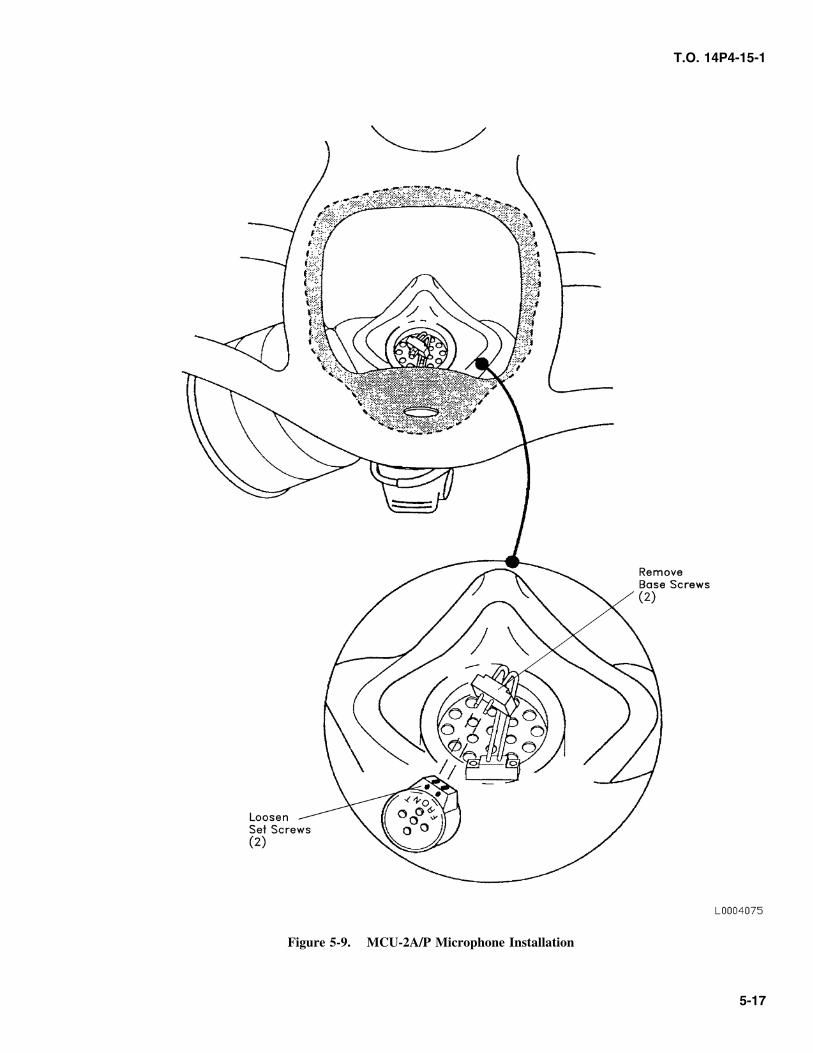
T.O. 14P4-15-1
Figure 5-9. MCU-2A/P Microphone Installation
5-17
T.O. 14P4-15-1
(6) Tighten two set screws located at base of (1) Upgrade H-133 headset assemblies, to conformmicrophone using a 0.066 wide bladed screw- with the latest change to the specification asdriver if using a M101/1C microphone. Other follows:microphones use a hexhead set screw. This
(a) Order plug assemblies 172/U, part No.requires a hexwrench to tighten the set screws.102950, NSN 5935-01-125-4897, andThe set screws when tight will lock microphoneU173/U, part No. 119563, NSN 5935-00-in place.888-5351.
(7) Check mask microphone with a compatible(b) Cut microphone cord halfway between theworking communications system and test the
headset and the microphone assembly, installsystem to make sure that everything is in work-the female plug U172/U on the headset halfing order.of the lead and the male U173/U on the
(8) Some microphones are available with an addi- microphone lead.tional attachment by means of two 2-56 screws.
(c) Use adapter lead CX4434/U, part No. 31500,These two screws are assembled through holesNSN 5995-00-890-8614, or equivalent asin the microphone connector and threaded intoneeded, to reach microphone plug.the base of the microphone housing.
(2) This work must be accomplished by a person(9) Position microphone in a comfortable positionqualified in electrical/electronic soldering, fol-close to the clips. The two black connectorlowing standard maintenance procedures.wires are flexible and can be positioned easily.
b. Upgrading H-133 Headset-Microphone to Allow 5.19 OUTSERT RUBBER STRAP REPLACEMENT.Connection to MCU-2A/P Gas Mask.
a. Removal - Pull on ends of rubber strap until theyNOTE pop loose.
b. Installation - Push in ends of rubber strap into holesSome noise suppression headset-microphoneon outsert until they enter fully. Remove anysets H-133, part No. M87819/1-01 NSN 5965-excess stem as required.01-204-8505 do not have plug connectors
between the headset and microphone assem-blies, thus not allowing the connection ofmask’s internal microphone.
5-18
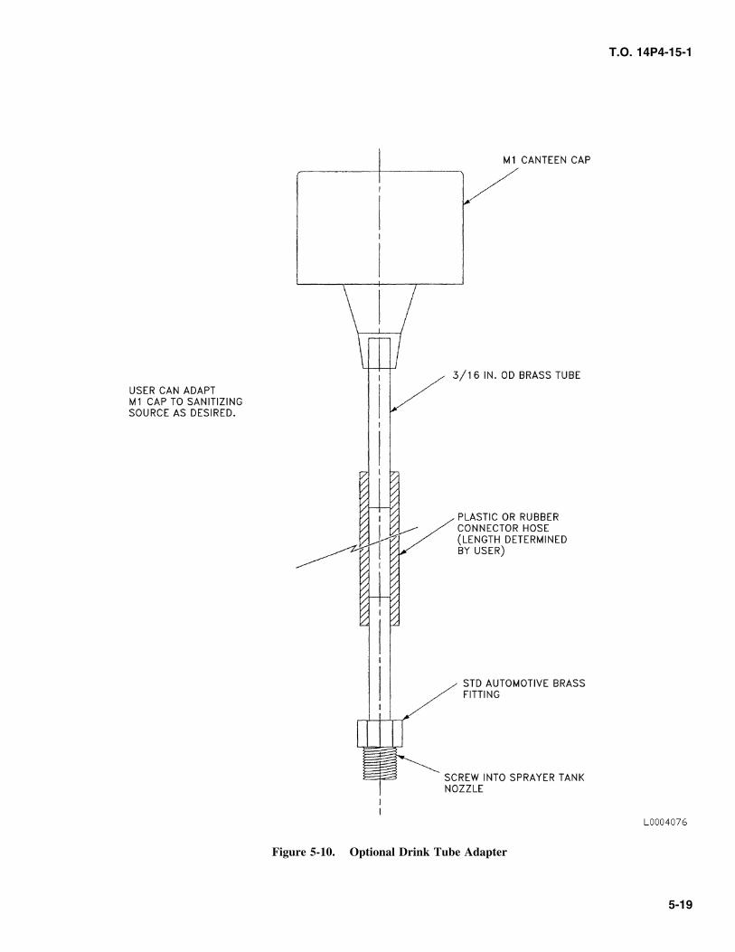
T.O. 14P4-15-1
Figure 5-10. Optional Drink Tube Adapter
5-19
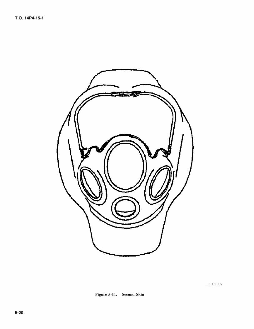
T.O. 14P4-15-1
Figure 5-11. Second Skin
5-20
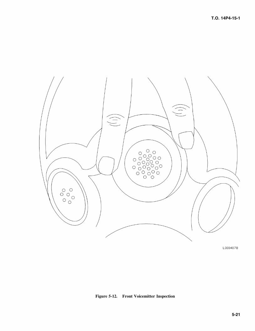
T.O. 14P4-15-1
Figure 5-12. Front Voicemitter Inspection
5-21
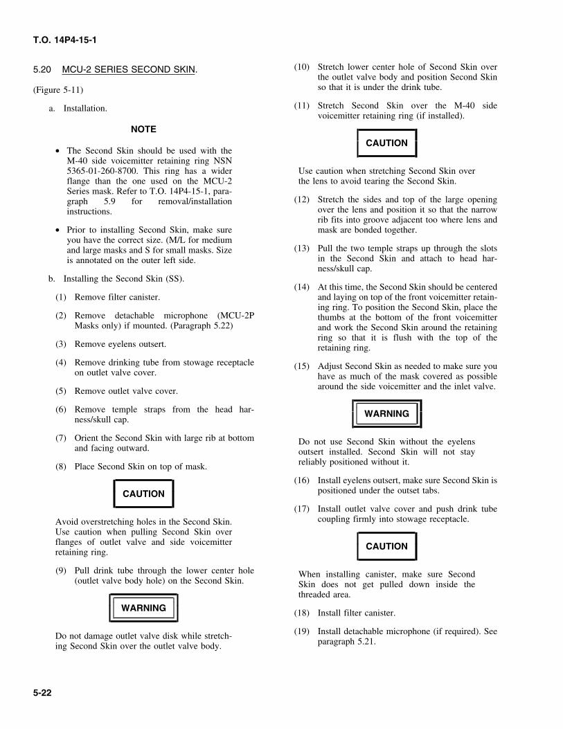
T.O. 14P4-15-1
(10) Stretch lower center hole of Second Skin over5.20 MCU-2 SERIES SECOND SKIN.the outlet valve body and position Second Skinso that it is under the drink tube.(Figure 5-11)
(11) Stretch Second Skin over the M-40 sidea. Installation.voicemitter retaining ring (if installed).
NOTE
CAUTION• The Second Skin should be used with the
M-40 side voicemitter retaining ring NSN5365-01-260-8700. This ring has a wider Use caution when stretching Second Skin overflange than the one used on the MCU-2 the lens to avoid tearing the Second Skin.Series mask. Refer to T.O. 14P4-15-1, para-
(12) Stretch the sides and top of the large openinggraph 5.9 for removal/installationover the lens and position it so that the narrowinstructions.rib fits into groove adjacent too where lens and
• Prior to installing Second Skin, make sure mask are bonded together.you have the correct size. (M/L for medium
(13) Pull the two temple straps up through the slotsand large masks and S for small masks. Sizein the Second Skin and attach to head har-is annotated on the outer left side.ness/skull cap.
b. Installing the Second Skin (SS).(14) At this time, the Second Skin should be centered
(1) Remove filter canister. and laying on top of the front voicemitter retain-ing ring. To position the Second Skin, place the
(2) Remove detachable microphone (MCU-2P thumbs at the bottom of the front voicemitterMasks only) if mounted. (Paragraph 5.22) and work the Second Skin around the retaining
ring so that it is flush with the top of the(3) Remove eyelens outsert. retaining ring.
(4) Remove drinking tube from stowage receptacle (15) Adjust Second Skin as needed to make sure youon outlet valve cover. have as much of the mask covered as possible
around the side voicemitter and the inlet valve.(5) Remove outlet valve cover.
(6) Remove temple straps from the head har- WARNINGness/skull cap.
(7) Orient the Second Skin with large rib at bottom Do not use Second Skin without the eyelensand facing outward. outsert installed. Second Skin will not stay
reliably positioned without it.(8) Place Second Skin on top of mask.
(16) Install eyelens outsert, make sure Second Skin ispositioned under the outset tabs.CAUTION
(17) Install outlet valve cover and push drink tubecoupling firmly into stowage receptacle.Avoid overstretching holes in the Second Skin.
Use caution when pulling Second Skin overflanges of outlet valve and side voicemitter CAUTIONretaining ring.
(9) Pull drink tube through the lower center hole When installing canister, make sure Second(outlet valve body hole) on the Second Skin. Skin does not get pulled down inside the
threaded area.
WARNING (18) Install filter canister.
(19) Install detachable microphone (if required). SeeDo not damage outlet valve disk while stretch-paragraph 5.21.ing Second Skin over the outlet valve body.
5-22
T.O. 14P4-15-1
(6) In a Contamination Control Area (CCA) replacehood, Second Skin and outsert.
WARNING
5.21 DETACHABLE MICROPHONE
Second Skin can not be changed in a contami- INSTRUCTIONS.nated environment.
Installing detachable microphone (only for MCU-2Pc. Removing non-contaminated Second Skin. To masks)
remove non-contaminated Second Skin follow theinstallation instructions in reverse order. a. Hold facepiece in your hand with the front
voicemitter facing you.d. Removing contaminated Second Skin.
b. Hold detachable microphone clipin your hand withthe ring opening facing down, and the flat surface
CAUTION facing towards the facepiece.
c. Insert the clip into the voicemitter housing with theWhen using a sharp instrument to remove Sec- cord at the six O’clock position.ond Skin, be sure you only cut the Second Skinand not the mask or straps. d. Snap the clip into place by pushing on the
microphone casing, making sure it is flush against(1) Remove eyelens outsert. the front voicemitter.
(2) Cut the two slots where the temple straps go5.22 REMOVING DETACHABLE MICROPHONE.through the Second Skin.
a. Hold the facepiece in your hand with the front(3) Cut the Second Skin at the top of the frontvoicemitter facing you.voicemitter and between the front voicemitter
and the top of the outlet valve housing.b. Place index finger on either side of the microphone
at the three O’clock position or nine O’clock(4) Cut the Second Skin between the large eyelensposition. Apply a sideward force until extracted.opening and the opening for the canister and the
side voicemitter.
(5) Remove Second Skin and dispose of in accor-dance with local standard operating procedures(SOP) for disposing of contaminated equipment.
5-23/(5-24 blank)

T.O. 14P4-15-1
CHAPTER 6ILLUSTRATED PARTS BREAKDOWN
SECTION I FOREWORD
6.1 GENERAL. 6.7 ABBREVIATIONS AND SYMBOLS.
This chapter contains the Illustrated Parts Breakdown (IPB) All abbreviations used in this publication are contained inwhich assists the supply and maintenance personnel in the the following list:identification and requistioning of replaceable parts.
ABBREVIATIONS DEFINITION6.2 PURPOSE. Assy Assembly
Ave. AvenueThe Illustrated Parts Breakdown (IPB) is prepared to assist
CAGE Commercial andsupply and maintenance personnel in hte identification,Government Entityrequistioning and stocking of replaceable parts. The IPB is
not intended to be used as a authority for procedure of CB Chemical Biologicaldisassembly or assembly. Maintenance or repair should be °F Degrees Fahrenheitperformed by authorized personnel using the applicable
I & S Interchangeablemaintenance sections of this manualand Substitute
IAW In Accordance With6.3 INTRODUCTION.IPB Illustrated Parts
The introduction contains general and specific information Breakdownpertaining to use of the IPB. MPL Maintenance Parts
List6.4 GROUP ASSEMBLY PARTS LISTS. NSN National Stock
NumberThe assemblies and parts installed a the time the MCU-2
PN Part NumberSeries mask was procured are listed and identified in themanual. When an assembly or part (including vendor RC Riot Controlitems), which is different from the original, was installed SMR Source, Maintenance andduring themanufacture of alter items, series, or blocks, all Recoverabilityassemblies and parts are listed (and ″‘Usable on″ coded).However, when the original assembly or part does not have
6.8 COMMERCIAL AND GOVERNMENT ENTITYcontinued application (no spares are no longer authorizedfor replacement), only the preferred assembly or part is (CAGE).listed. Also, when an assembly or part was installed duringmodification, and the original does not have continued This column lists the code of the manufacturer or supplierapplication, only the preferred item is listed. When a of the part listed in the Part number Column. Refer to thestandard size part, the latter parts, showing sizes, are also handbook of commercial and Government Entity codes.listed. Repair Parts Kits and Quick Change Units are listed Cataloging Handbook H4/H8 for all manufactures supply-when they are available for replacement. ing items or articles not carried under prime contractor’s
part numbers.6.5 MAINTENANCE PARTS LIST.
6.9 NUMERICAL LISTING.This MPL describes, and illustrates the assemblies, subas-semblies and detail parts of the MCU-2 Series mask. All CAGE listed in the CAGE column of the Maintenance
Parts List (MPL) are arranged in numerical sequence with6.6 MODELS COVERED. the complete name and address of the appropriate manufac-
turer or Government Agency following each CAGE asMCU-2A/P and MCU-2P follows:
6-1
T.O. 14P4-15-1
CAGE NAME AND ADDRESS NAME AND ADDRESS CAGE03038 Long-Lok Fasteners Corp Sonetronics Inc 16575
13709 S Normandie Ave 1718 H StreetGardena, CA 90249-2609 PO Box L
West Belmar, NJ 07719-314016575 Sonetronics Inc1718 H Street US Army, Soldier and Biological 81361PO Box L Chemical CommandWest Belmar, NJ 07719-3140 Edgewood Chemical Biological
Center53655 Scott Aviation A Div. of Scott5183 Blackhawk Rd.Technologies Inc.Gunpowder MD 21010–5424225 Erie Street
Lancaster, NY Warner Robins ALC 9875214086-9502 Robins AFB, GA 31098
55799 Mine Safety ApplianceCompany 6.11 USABLE ON CODE COLUMN.3880 Meadowbrook RoadMurrysville, PA 15668 This column contains suitable coding for assemblies and
parts to indicate specific usability by serial, type, model, or81349 Military Specificationsseries numbers of the articles for which the breakdown isPromulgated by Militaryprepared. Where the Usable On Code column has been leftDepartments/Agenciesblank, parts listed apply to all models covered by thisUnder Authority of Defensebreakdown.Standardization Manual 4120 3-M
92114 Scott Aviation6.12 SOURCE, MAINTENANCE ANDSierra Products Division
1900 Walker Ave RECOVERABILITY (SMR) CODES.Monrovia, CA 91016
Definitions of applicable Source, Maintenance, and Recov-98752 Warner Robins ALCerability Codes (SMR) are set forth in T.O. 00-25-195.Robins AFB, GA 31098
6.13 APPLICABLE TIME COMPLIANCE6.10 ALPHABETICAL LISTING.TECHNICAL ORDERS (TCTO).
All manufacturers and Government Agencies listed in thedescription column of the MPL are listed in alphabetical None.sequence as follows:
NAME AND ADDRESS CAGELong-Lok Fasteners Corp. 0303813709 S Normandie AveGardena, CA 90249-2609
Mine Safety Appliance 55799Company3880 Meadowbrook RoadMurrysville, PA 15668
6-2
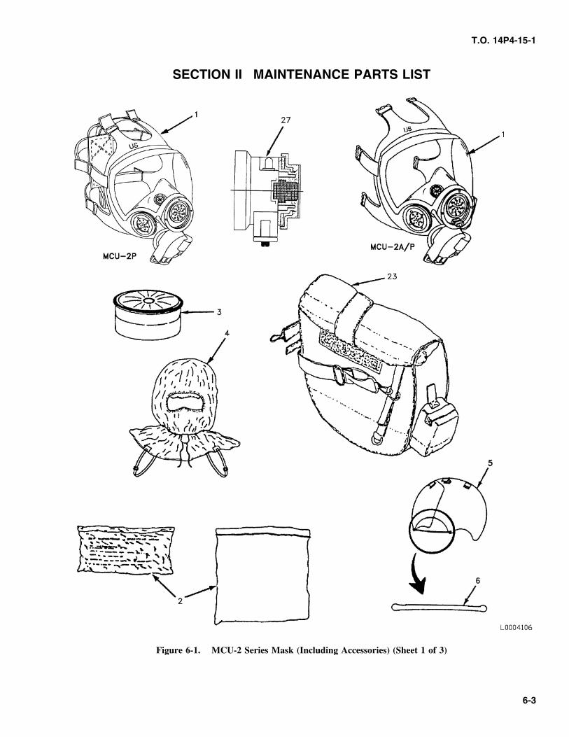
T.O. 14P4-15-1
SECTION II MAINTENANCE PARTS LIST
Figure 6-1. MCU-2 Series Mask (Including Accessories) (Sheet 1 of 3)
6-3
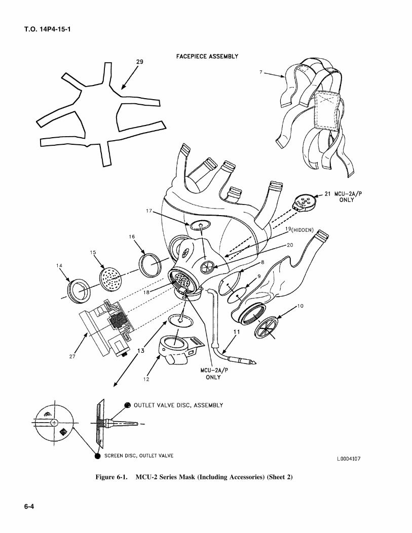
T.O. 14P4-15-1
Figure 6-1. MCU-2 Series Mask (Including Accessories) (Sheet 2)
6-4
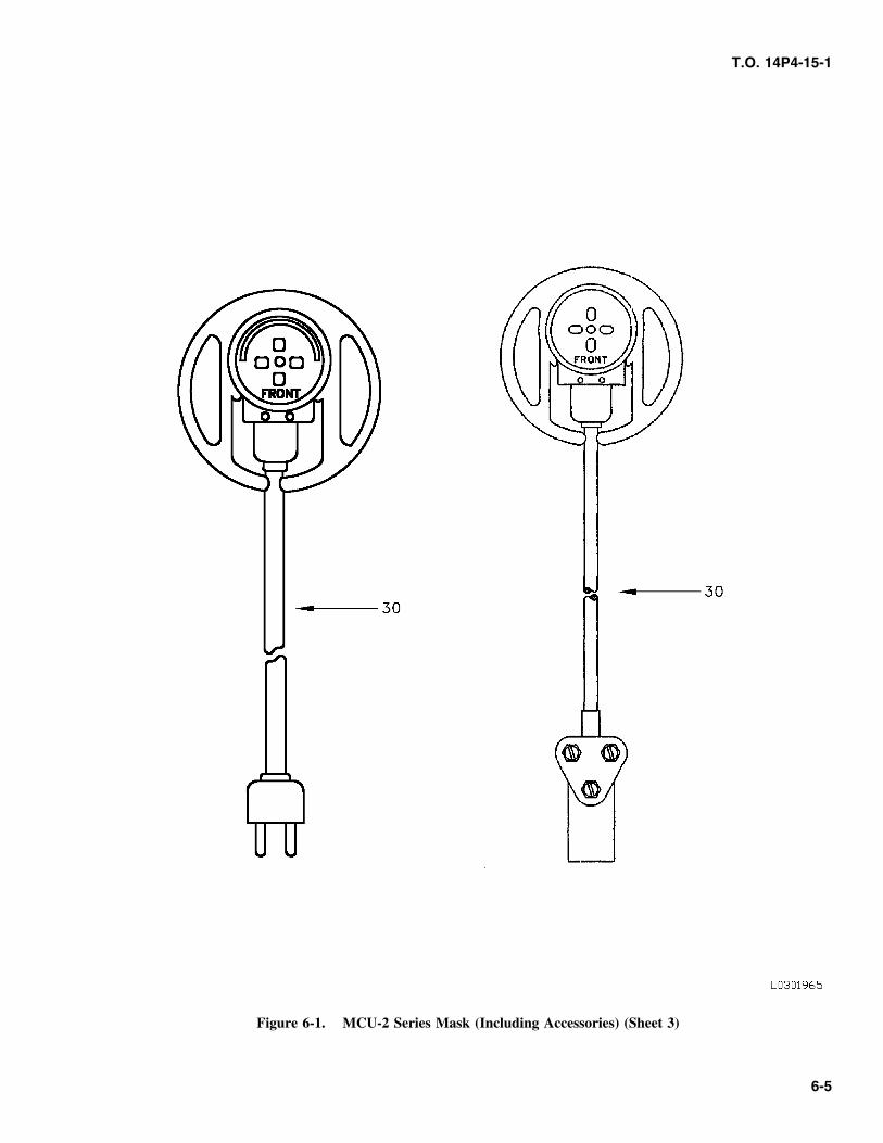
T.O. 14P4-15-1
Figure 6-1. MCU-2 Series Mask (Including Accessories) (Sheet 3)
6-5
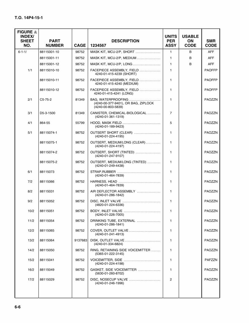
T.O. 14P4-15-1
FIGURE &INDEX/ UNITS USABLESHEET PART DESCRIPTION PER ON SMR
NO. NUMBER CAGE 1234567 ASSY CODE CODE
6-1-1/ 88115001-10 98752 MASK KIT, MCU-2/P, SHORT . . . . . . . . . . . . . . . . . . . 1 B AFF
88115001-11 98752 MASK KIT, MCU-2/P, MEDIUM . . . . . . . . . . . . . . . . . . 1 B AFF
88115001-12 98752 MASK KIT, MCU-2/P, LONG . . . . . . . . . . . . . . . . . . . . . 1 B AFF
1/1 88115010-10 98752 FACEPIECE ASSEMBLY, FIELD . . . . . . . . . . . . . . . . 1 PAOFFP 4240-01-415-4239 (SHORT)
88115010-11 98752 FACEPIECE ASSEMBLY, FIELD . . . . . . . . . . . . . . . . 1 PAOFFP 4240-01-415-4240 (MEDIUM)
88115010-12 98752 FACEPIECE ASSEMBLY, FIELD . . . . . . . . . . . . . . . . 1 PAOFFP4240-01-415-4241 (LONG)
2/1 C5-75-2 81349 BAG, WATERPROOFING . . . . . . . . . . . . . . . . . . . . . . . . 1 PAOZZN(4240-00-377-9401), OR BAG, ZIPLOCK(4240-00-803-5839)
3/1 D5-3-1500 81349 CANISTER, CHEMICAL-BIOLOGICAL . . . . . . . . . . 7 PAOZZN (4240-01-361-1319)
4/1 864-55 55799 HOOD, MASK FIELD . . . . . . . . . . . . . . . . . . . . . . . . . . . . . 5 PAOZZN (4240-01-189-9423)
5/1 88115074-1 98752 OUTSERT SHORT (CLEAR) . . . . . . . . . . . . . . . . . . . . 1 PAOZZN (4240-01-224-4195)
88115075-1 98752 OUTSERT, MEDIUM/LONG (CLEAR) . . . . . . . . . . . 1 PAOZZN (4240-01-224-4197)
88115074-2 98752 OUTSERT, SHORT (TINTED) . . . . . . . . . . . . . . . . . . . 1 PAOZZN (4240-01-247-9107)
88115075-2 98752 OUTSERT, MEDIUM/LONG (TINTED) . . . . . . . . . . 1 PAOZZN (4240-01-249-4438)
6/1 88115073 98752 STRAP,RUBBER . . . . . . . . . . . . . . . . . . . . . . . . . . . . . . . . . 1 PAOZZN (4240-01-464-7839)
7/2 88115066 98752 HARNESS, HEAD . . . . . . . . . . . . . . . . . . . . . . . . . . . . . . . . 1 PAOZZN (4240-01-464-7839)
8/2 88115031 98752 AIR DEFLECTOR ASSEMBLY . . . . . . . . . . . . . . . . . . 1 PAOZZN (4240-01-286-1842)
9/2 88115052 98752 DISC, INLET VALVE . . . . . . . . . . . . . . . . . . . . . . . . . . . . . 1 PAOZZN (4820-01-224-6336)
10/2 88115051 98752 BODY, INLET VALVE . . . . . . . . . . . . . . . . . . . . . . . . . . . . 1 PAOZZN (4240-01-226-7005)
11/2 88115054 98752 DRINKING TUBE, EXTERNAL . . . . . . . . . . . . . . . . . . 1 PAOZZN (4240-01-286-1841)
12/2 88115065 98752 COVER, OUTLET VALVE . . . . . . . . . . . . . . . . . . . . . . . . 1 PAOZZN (4240-01-241-4913)
13/2 88115064 9137683 DISK, OUTLET VALVE . . . . . . . . . . . . . . . . . . . . . . . . . . . 1 PAOZZN(4240-01-334-6824)
14/2 88115050 98752 RING, RETAINING SIDE VOICEMITTER . . . . . . . 1 PAOZZN (5365-01-222-3145)
15/2 88115041 98752 VOICEMITTER, SIDE . . . . . . . . . . . . . . . . . . . . . . . . . . . . 1 PAFZZN (4240-01-224-4198)
16/2 88115049 98752 GASKET, SIDE VOICEMITTER . . . . . . . . . . . . . . . . . 1 PAOZZN (5630-01-260-8702)
17/2 88115029 98752 DISC, NOSECUP VALVE . . . . . . . . . . . . . . . . . . . . . . . . 2 PAOZZN (4240-01-246-1996)
6-6
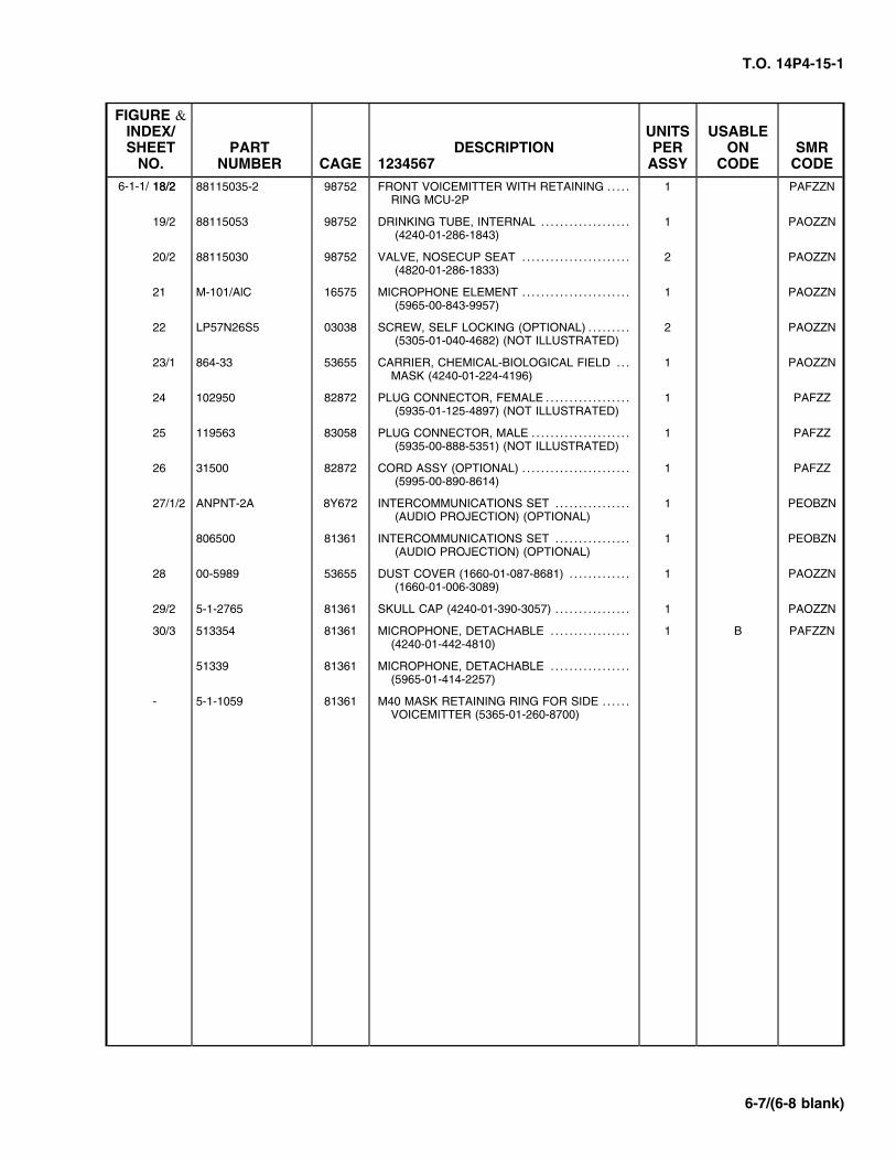
T.O. 14P4-15-1
6-1-1/ 18/2
FIGURE &INDEX/ UNITS USABLESHEET PART DESCRIPTION PER ON SMR
NO. NUMBER CAGE 1234567 ASSY CODE CODE
18/2 88115035-2 98752 FRONT VOICEMITTER WITH RETAINING . . . . . 1 PAFZZNRING MCU-2P
19/2 88115053 98752 DRINKING TUBE, INTERNAL . . . . . . . . . . . . . . . . . . . 1 PAOZZN (4240-01-286-1843)
20/2 88115030 98752 VALVE, NOSECUP SEAT . . . . . . . . . . . . . . . . . . . . . . . 2 PAOZZN (4820-01-286-1833)
21 M-101/AlC 16575 MICROPHONE ELEMENT . . . . . . . . . . . . . . . . . . . . . . . 1 PAOZZN (5965-00-843-9957)
22 LP57N26S5 03038 SCREW, SELF LOCKING (OPTIONAL) . . . . . . . . . 2 PAOZZN (5305-01-040-4682) (NOT ILLUSTRATED)
23/1 864-33 53655 CARRIER, CHEMICAL-BIOLOGICAL FIELD . . . 1 PAOZZNMASK (4240-01-224-4196)
24 102950 82872 PLUG CONNECTOR, FEMALE . . . . . . . . . . . . . . . . . . 1 PAFZZ (5935-01-125-4897) (NOT ILLUSTRATED)
25 119563 83058 PLUG CONNECTOR, MALE . . . . . . . . . . . . . . . . . . . . . 1 PAFZZ (5935-00-888-5351) (NOT ILLUSTRATED)
26 31500 82872 CORD ASSY (OPTIONAL) . . . . . . . . . . . . . . . . . . . . . . . 1 PAFZZ (5995-00-890-8614)
27/1/2 ANPNT-2A 8Y672 INTERCOMMUNICATIONS SET . . . . . . . . . . . . . . . . 1 PEOBZN (AUDIO PROJECTION) (OPTIONAL)
806500 81361 INTERCOMMUNICATIONS SET . . . . . . . . . . . . . . . . 1 PEOBZN (AUDIO PROJECTION) (OPTIONAL)
28 00-5989 53655 DUST COVER (1660-01-087-8681) . . . . . . . . . . . . . 1 PAOZZN (1660-01-006-3089)
29/2 5-1-2765 81361 SKULL CAP (4240-01-390-3057) . . . . . . . . . . . . . . . . 1 PAOZZN
30/3 513354 81361 MICROPHONE, DETACHABLE . . . . . . . . . . . . . . . . . 1 B PAFZZN(4240-01-442-4810)
51339 81361 MICROPHONE, DETACHABLE . . . . . . . . . . . . . . . . .(5965-01-414-2257)
- 5-1-1059 81361 M40 MASK RETAINING RING FOR SIDE . . . . . .VOICEMITTER (5365-01-260-8700)
6-7/(6-8 blank)

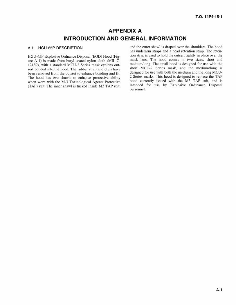
T.O. 14P4-15-1
APPENDIX AINTRODUCTION AND GENERAL INFORMATION
and the outer shawl is draped over the shoulders. The hoodA.1 HGU-65P DESCRIPTION.has underarm straps and a head retention strap. The reten-tion strap is used to hold the outsert tightly in place over theHGU-65P Explosive Ordnance Disposal (EOD) Hood (Fig-mask lens. The hood comes in two sizes, short andure A-1) is made from butyl-coated nylon cloth (MIL-C-medium/long. The small hood is designed for use with the12189), with a standard MCU-2 Series mask eyelens out-short MCU-2 Series mask, and the medium/long issert bonded into the hood. The rubber strap and clips havedesigned for use with both the medium and the long MCU-been removed from the outsert to enhance bonding and fit.2 Series masks. This hood is designed to replace the TAPThe hood has two shawls to enhance protective abilityhood currently issued with the M3 TAP suit, and iswhen worn with the M-3 Toxicological Agents Protectiveintended for use by Explosive Ordinance Disposal(TAP) suit. The inner shawl is tucked inside M3 TAP suit,personnel.
A-1
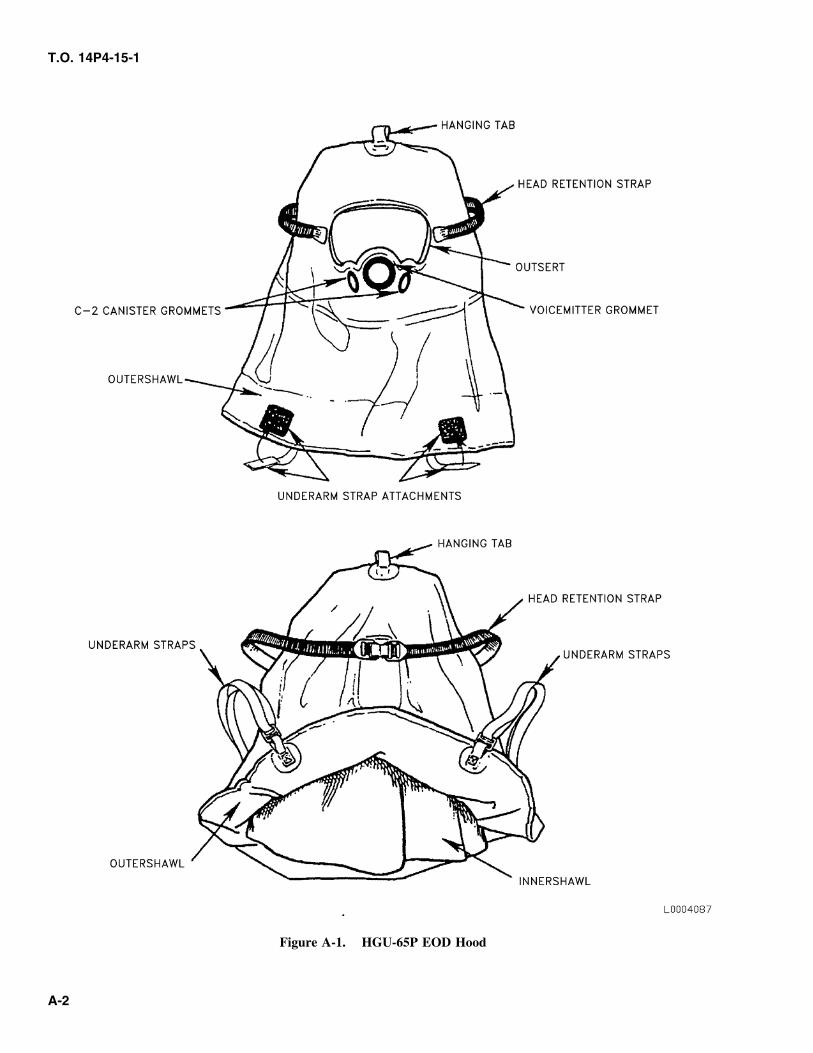
T.O. 14P4-15-1
Figure A-1. HGU-65P EOD Hood
A-2
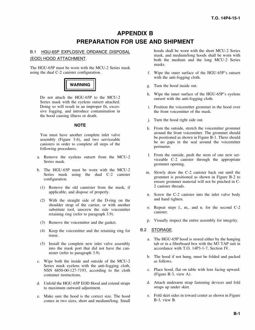
T.O. 14P4-15-1
APPENDIX BPREPARATION FOR USE AND SHIPMENT
hoods shall be worn with the short MCU-2 SeriesB.1 HGU-65P EXPLOSIVE ORDANCE DISPOSALmask, and medium/long hoods shall be worn with
(EOD) HOOD ATTACHMENT. both the medium and the long MCU-2 Seriesmasks.
The HGU-65P must be worn with the MCU-2 Series maskusing the dual C-2 canister configuration. f. Wipe the outer surface of the HGU-65P’s outsert
with the anti-fogging cloth.
WARNING g. Turn the hood inside out.
h. Wipe the inner surface of the HGU-65P’s eyelensDo not attach the HGU-65P to the MCU-2 outsert with the anti-fogging cloth.Series mask with the eyelens outsert attached.Doing so will result in an improper fit, exces- i. Position the voicemitter grommet in the hood oversive fogging, and introduce contamination in the front voicemitter of the mask.the hood causing illness or death.
j. Turn the hood right side out.NOTE
k. From the outside, stretch the voicemitter grommetaround the front voicemitter. The grommet shouldYou must have another complete inlet valvebe positioned as shown in Figure B-1. There shouldassembly (Figure 3-6), and two serviceablebe no gaps in the seal around the voicemittercanisters in order to complete all steps of theperimeter.following procedures.
l. From the outside, push the stem of one new ser-a. Remove the eyelens outsert from the MCU-2viceable C-2 canister through the appropriateSeries mask.grommet opening.
b. The HGU-65P must be worn with the MCU-2m. Slowly draw the C-2 canister back out until theSeries mask using the dual C-2 canister
grommet is positioned as shown in Figure B-2 toconfiguration.ensure grommet material will not be pinched in C-2 canister threads.(1) Remove the old cannister from the mask, if
applicable, and dispose of properly.n. Screw the C-2 canister into the inlet valve body
and hand tighten.(2) With the straight side of the D-ring on theshoulder strap of the carrier, or with another
o. Repeat steps l., m., and n. for the second C-2substitute tool, unscrew the side voicemittercanister.retaining ring (refer to paragraph 3.9).
p. Visually inspect the entire assembly for integrity.(3) Remove the voicemitter and the gasket.
B.2 STORAGE.(4) Keep the voicemitter and the retaining ring forreuse.
a. The HGU-65P hood is stored either by the hanging(5) Install the complete new inlet valve assembly tab or in a fiberboard box with the M3 TAP suit in
into the mask port that did not have the can- accordance with T.O. 14P3-1-7, Section IV.nister (refer to paragraph 3.9).
b. The hood if not hung, must be folded and packedc. Wipe both the inside and outside of the MCU-2 as follows.
Series mask eyelens with the anti-fogging cloth,c. Place hood, flat on table with lens facing upward.NSN 6850-00-127-7193, according to the cloth
(Figure B-3, view A).container instructions.
d. Attach underarm strap fastening devices and foldd. Unfold the HGU-65P EOD Hood and extend strapsstraps up under skirt.to maximum outward adjustment.
e. Fold skirt sides in toward center as shown in Figuree. Make sure the hood is the correct size. The hoodB-3, view B.comes in two sizes, short and medium/long. Small
B-1
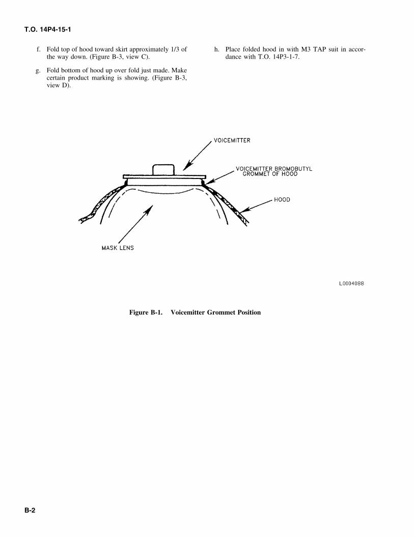
T.O. 14P4-15-1
f. Fold top of hood toward skirt approximately 1/3 of h. Place folded hood in with M3 TAP suit in accor-the way down. (Figure B-3, view C). dance with T.O. 14P3-1-7.
g. Fold bottom of hood up over fold just made. Makecertain product marking is showing. (Figure B-3,view D).
Figure B-1. Voicemitter Grommet Position
B-2
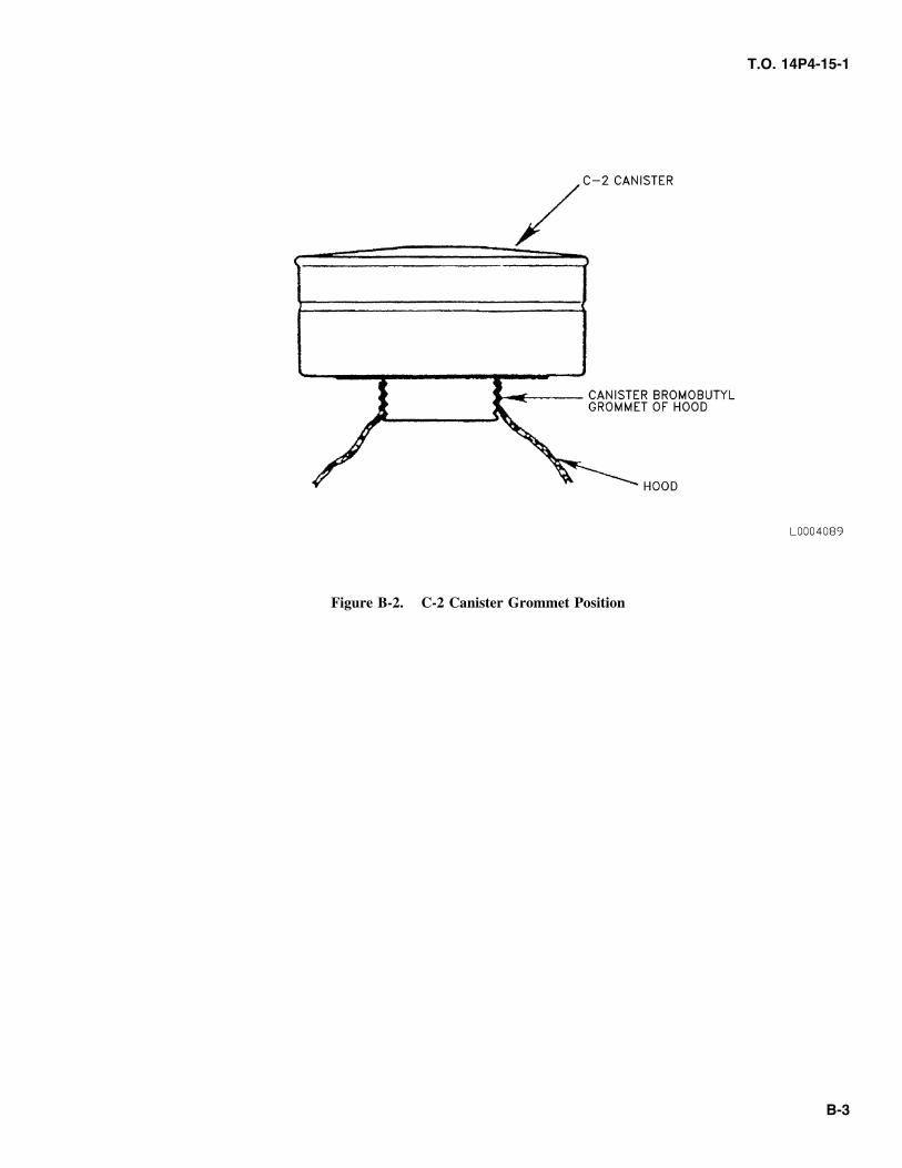
T.O. 14P4-15-1
Figure B-2. C-2 Canister Grommet Position
B-3
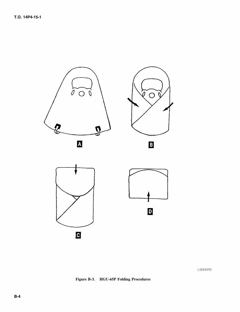
T.O. 14P4-15-1
Figure B-3. HGU-65P Folding Procedures
B-4
T.O. 14P4-15-1
APPENDIX COPERATION INSTRUCTIONS
tightly against chin. Pull head harness over headC.1 DONNING PROCEDURES FOR MASKS WITHusing the quick-don tab.
HGU-65P EOD HOODS.e. The buddy will tighten the head harness by grasp-
ing a neck strap in each hand and tightening withWARNING small jerking motions. The wearer shall indicate
the head harness is sufficiently tight both visuallyand audibly.
The drinking tube is inaccessible when theHGU-65P EOD Hood is worn with the MCU-2 f. The wearer shall perform negative pressure checkSeries mask. Do not attempt to access the (Refer to T.O. 14P4-15-1, Chapter 3) to ensure andrinking tube. Doing so may expose the wearer airtight seal.to high concentrations of toxic agents, causingillness or death. g. With the assistance of the buddy, unroll the rear
portion of the hood to cover the back of the head.NOTE Drape the hood over the shoulders.
• These procedures presume the following: NOTE
• Unapproved eyewear and/or contact lenses The HGU-65P hood outsert must form a sealhave been removed. around the entire perimeter of the MCU-2
Series mask eyelens. Failure to do so will result• Appropriate ear protection is in place, if in an improper fit, which could result in exces-applicable. sive fogging of the outsert.
• The MCU-2 Series mask temple and fore- h. The buddy will tighten the HGU-65P head reten-head straps have been preadjusted (Refer to tion strap by grasping a strap in each hand andChapter 3) tightening with small jerking motions. The wearer
shall indicate the retention strap is sufficiently tight• These procedures assume the following:both visually and audibly.
• Donning in an uncontaminated environment,i. The buddy shall visually inspect the outsert seal tousing a BUDDY SYSTEM for donning.
the MCU-2 Series mask eyelens to ensure the sealis touching the eyelens in all places.• The M3 TAP suit, and/or the M2 TAP apron
(as appropriate) has been donned, accordingj. If wearing the hood with the M2 Toxicologicalto T.O. 60A-1-1-11.
Agents Protective (TAP) apron only, proceed tostep n. If wearing the hood with the M3 TAP suit,Don the mask/hood assembly in the following steps:proceed to the following step.
a. Roll the rear portion of the hood upward to exposek. Using both hands, the wearer will raise the outerthe head harness of the mask.
shawl off the shoulders.b. Turn the mask harness inside out over the mask.
l. The buddy will tuck the inner shawl into the M3c. Reach inside the hood with one hand and place the TAP suit, minimizing bunching of the inner shawl
outlet valve assembly area in the palm of that hand. fabric by making one or two smooth folds.
m. The buddy will pull the M3 TAP suit up over theWARNING wearer’s shoulders, and finish closure of the TAP
suit (refer to T.O. 60A-1-1-11).
When donning the mask/hood assembly do not n. The wearer and buddy will place the outer shawlblock the canisters. The wearer may suffocate over the wearer’s shoulders.if the hood fabric blocks them.
o. The buddy will pass the straps under the wearer’sd. Using the free hand, push forehead hair aside. arms and fasten the straps to the front of the outer
Place the mask on face forcing the chin cup very shawl by pressing the two parts of the fastening
C-1
T.O. 14P4-15-1
device together. Adjust the straps as necessary to (3) Wash by hand in warm water using mild soap.obtain a comfortable fit.
(4) Rinse in cool water and hang in open air to dry.
C.2 DOFFING PROCEDURES FOR MASKS WITHb. Fuming nitric acid exposure.
HGU-65P EOD HOODS.(1) Wash thoroughly in water.
This procedure assumes the use of the buddy system in(2) Sponge off with a 5 to 10 percent sodiumdoffing the mask and hood. This procedure also assumes
bicarbonate solution.the M3 TAP suit, and/or the M2 TAP apron (as appropri-ate) has been removed. The underarm straps should, there-
(3) Rinse thoroughly with clear water and hang infore, already be unfastened.open air to dry.
a. The buddy will loosen the HGU-65P head retentionc. Hydrazine/UDMH or nitrogen tetroxide exposure.straps.
(1) Wash with household laundry detergent andwater solution.WARNING
(2) Rinse thoroughly with clear water and hang inopen air to dry.When doffing the mask/hood assembly do not
block the canisters. The wearer may suffocateif the hood fabric blocks them. CAUTION
b. Roll the back of the two shawls forward over thehead and leave the hood suspended from the front Damage to the HGU 65P’s outsert will occur ifof the mask. Do not block the canisters with the decontaminated using personal decon kits.rolled up hood. Decontaminate according to T.O. 11C15-1-3
and T.O. 60A-1-1-11.c. The buddy will loosen the mask neck straps. Thewearer will grasp the mask in the outlet valve area d. Chemical warfare agent decontamination.(without reaching inside the reversed hood) andremove by pulling down, outward, and up. C.4 MCU-2 SERIES MASK CLEANING.
C.3 HGU-65/P CLEANING. Refer T.O. 14P4-15-1, Chapter 5.
a. Uncontaminated.
(1) Unscrew and remove both C-2 canisters.
(2) Separate hood from mask (in reverse order ofhood attachment).
C-2
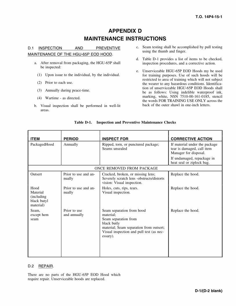
T.O. 14P4-15-1
APPENDIX DMAINTENANCE INSTRUCTIONS
c. Seam testing shall be accomplished by pull testingD.1 INSPECTION AND PREVENTIVEusing the thumb and finger.
MAINTENANCE OF THE HGU-65P EOD HOOD.d. Table D-1 provides a list of items to be checked,
a. After removal from packaging, the HGU-65P shall inspection procedures, and a corrective action.be inspected:
e. Unserviceable HGU-65P EOD Hoods my be used(1) Upon issue to the individual, by the individual. for training purposes. Use of such hoods will be
restricted to area of training which will not subject(2) Prior to each use. the wearer to any hazardous conditions. Identifica-
tion of unserviceable HGU-65P EOD Hoods shall(3) Annually during peace-time. be as follows: Using indelible waterproof ink,
marking, white, NSN 7510-00-161-0185, stencil(4) Wartime - as directed.the words FOR TRAINING USE ONLY across theback of the outer shawl in one-inch letters.b. Visual inspection shall be performed in well-lit
areas.
Table D-1. Inspection and Preventive Maintenance Checks
ITEM PERIOD INSPECT FOR CORRECTIVE ACTIONPackagedHood Annually Ripped, torn, or punctured package; If material under the package
Seams unsealed tear is damaged, call itemManager for disposal.
If undamaged, repackage inheat seal or ziplock bag.
ONCE REMOVED FROM PACKAGE
Outsert Prior to use and an- Cracked, broken, or missing lens; Replace the hood.nually Severely scratch lens -obstructs/distorts
vision: Visual inspection.
Hood Prior to use and an- Holes, cuts, rips, tears. Replace the hood.Material nually Visual inspection.(includingblack butylmaterial)
Seam, Prior to use Seam separation from hood Replace the hood.except hem and annually material;seam Seam separation from
black butlymaterial; Seam separation from outsert;Visual inspection and pull test (as nec-essary).
D.2 REPAIR.
There are no parts of the HGU-65P EOD Hood whichrequire repair. Unserviceable hoods are replaced.
D-1/(D-2 blank)


![3.03 [Proposed North Elevation]€¦ · T.O. PARAPET 78.41’ T.O.PARAPET 89.31’ T.O. PARAPET 74.50’ (EXISTING) TOP 78.41’ T.O.PARAPET 89.31’ Point Grey Private Hospital Expansion](https://img.pdfslide.us/doc/110x75/608306638d4a9571f662c0e9/303-proposed-north-elevation-to-parapet-7841a-toparapet-8931a-to.jpg)