Embed Size (px)
Citation preview
TM1700-seriesCircuit Breaker Analyzer System
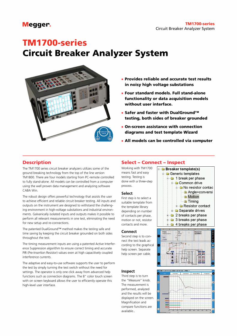
Provides reliable and accurate test results in noisy high voltage substations
Four standard models. Full stand-alone functionality or data acquisition models without user interface.
Safer and faster with DualGround™ testing, both sides of breaker grounded
On-screen assistance with connection diagrams and test template Wizard
All models can be controlled via computer
DescriptionThe TM1700 series circuit breaker analyzers utilizes some of the ground breaking technology from the top of the line version TM1800. There are four models starting from PC-remote controlled to fully stand-alone. All models can be controlled from a computer using the well proven data management and analyzing software CABA Win.
The robust design offers powerful technology that assists the user to achieve efficient and reliable circuit breaker testing. All inputs and outputs on the instrument are designed to withstand the challeng-ing environment in high-voltage substations and industrial environ-ments. Galvanically isolated inputs and outputs makes it possible to perform all relevant measurements in one test, eliminating the need for new setup and re-connections.
The patented DualGround™ method makes the testing safe and time saving by keeping the circuit breaker grounded on both sides throughout the test.
The timing measurement inputs are using a patented Active Interfer-ence Suppression algorithm to ensure correct timing and accurate PIR (Pre-Insertion Resistor) values even at high capacitively coupled interference currents.
The adaptive and easy-to-use software supports the user to perform the test by simply turning the test switch without the need for settings. The operator is only one click away from advanced help functions such as connection diagrams. The 8” color touch screen with on screen keyboard allows the user to efficiently operate this high-level user interface.
TM1700-seriesCircuit Breaker Analyzer System
Select – Connect – InspectWorking with TM1700 means fast and easy testing. Testing is done with a three-step process.
SelectFirst step is to select a suitable template from the template library depending on number of contacts per phase, motion or not, resistor contacts and more.
ConnectSecond step is to con-nect the test leads ac-cording to the graphical help screen. Separate help screen per cable.
InspectThird step is to turn the “Measure” knob. The measurement is performed, analyzed and the results will be displayed on the screen. Magnification and compare functions are available..
TM1700-seriesCircuit Breaker Analyzer System
2
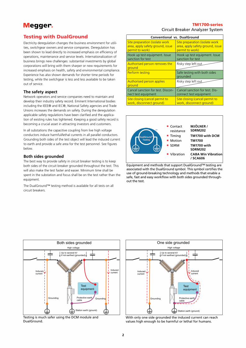
With only one side grounded the induced current can reach values high enough to be harmful or lethal for humans.
Testing is much safer using the DCM module and DualGround.
Contact resistance
MJÖLNER / SDRM202
Timing TM1700 with DCM Motion TM1700 SDRM TM1700 with
SDRM202 Vibration CABA Win Vibration
/ SCA606
Equipment and methods that support DualGround™ testing are associated with the DualGround symbol. This symbol certifies the use of ground-breaking technology and methods that enable a safe, fast and easy workflow with both sides grounded through-out the test.
Conventional vs. DualGroundSite preparation (isolate work area, apply safety ground, issue permit to work)
Site preparation (isolate work area, apply safety ground, issue permit to work)
Hook up test equipment. Issue sanction for test
Hook up test equipment. Issue sanction for test
Authorised person removes the ground
Risky step left out
Perform testing Safe testing with both sides grounded
Authorised person applies ground
Risky step left out
Cancel sanction for test. Discon-nect test equipment
Cancel sanction for test. Dis-connect test equipment
Site closing (cancel permit to work, disconnect ground)
Site closing (cancel permit to work, disconnect ground)
Testing with DualGroundElectricity deregulation changes the business environment for utili-ties, switchgear owners and service companies. Deregulation has been shown to lead directly to increased emphasis on efficiency of operations, maintenance and service levels. Internationalization of business brings new challenges: substantial investments by global corporations will bring with them sharper or new requirements for increased emphasis on health, safety and environmental compliance. Experience has also shown demands for shorter time periods for testing, while the switchgear is less and less available to be taken out of service.
The safety aspectNetwork operators and service companies need to maintain and develop their industry safety record. Eminent International bodies including the IEEE® and IEC®, National Safety agencies and Trade Unions increases the demands on safety. During the deregulation applicable safety regulations have been clarified and the applica-tion of existing rules has tightened. Keeping a good safety record is becoming a crucial asset in attracting investors and customers.
In all substations the capacitive coupling from live high voltage conductors induce harmful/lethal currents in all parallel conductors. Grounding both sides of the test object will lead the induced current to earth and provide a safe area for the test personnel. See figures below.
Both sides groundedThe best way to provide safety in circuit breaker testing is to keep both sides of the circuit breaker grounded throughout the test. This will also make the test faster and easier. Minimum time shall be spent in the substation and focus shall be on the test rather than the equipment.
The DualGround™ testing method is available for all tests on all circuit breakers.
TM1700-seriesCircuit Breaker Analyzer System
3
1 2 3 4 5 6 71 2
15 16 17 19 15 20 21 22 23
101112
18
9 14138
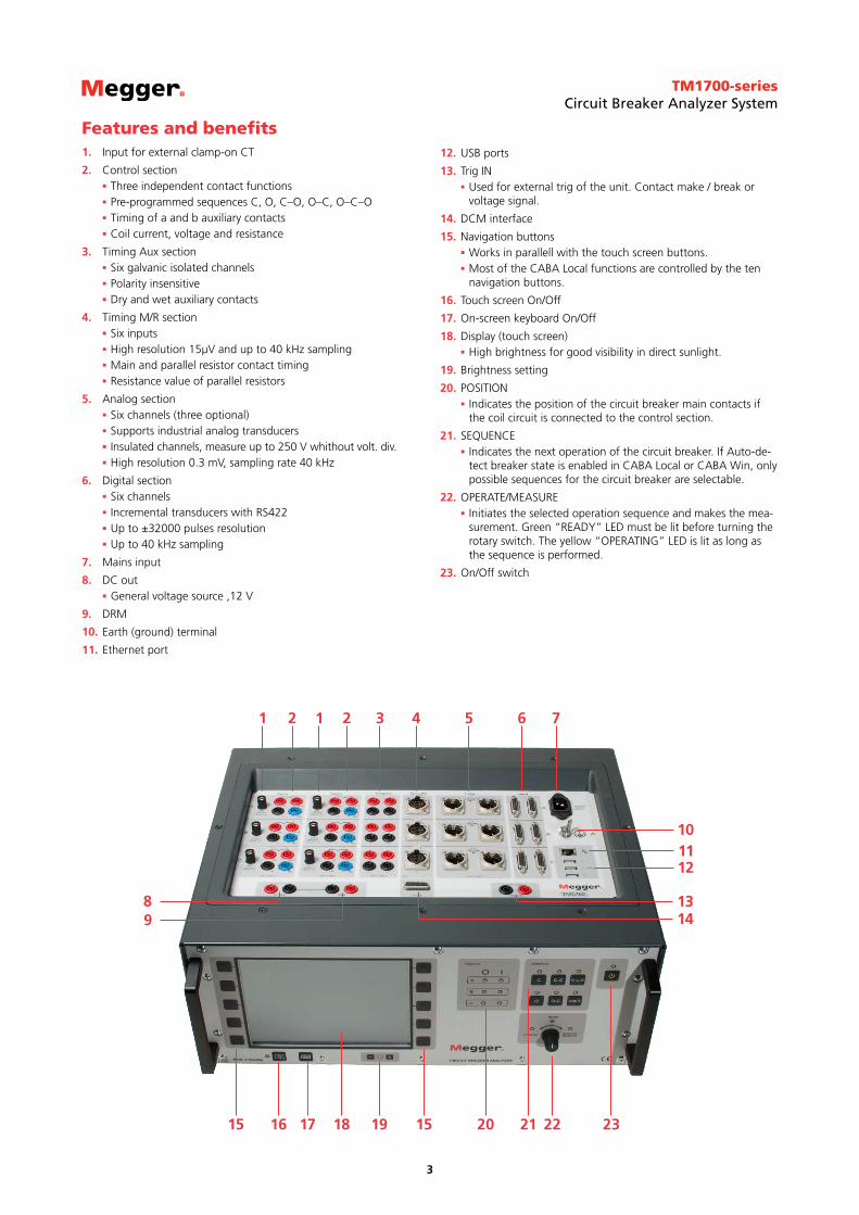
Features and benefits1. Input for external clamp-on CT
2. Control section Three independent contact functions Pre-programmed sequences C, O, C–O, O–C, O–C–O Timing of a and b auxiliary contacts Coil current, voltage and resistance
3. Timing Aux section Six galvanic isolated channels Polarity insensitive Dry and wet auxiliary contacts
4. Timing M/R section Six inputs High resolution 15μV and up to 40 kHz sampling Main and parallel resistor contact timing Resistance value of parallel resistors
5. Analog section Six channels (three optional) Supports industrial analog transducers Insulated channels, measure up to 250 V whithout volt. div. High resolution 0.3 mV, sampling rate 40 kHz
6. Digital section Six channels Incremental transducers with RS422 Up to ±32000 pulses resolution Up to 40 kHz sampling
7. Mains input
8. DC out General voltage source ,12 V
9. DRM
10. Earth (ground) terminal
11. Ethernet port
12. USB ports
13. Trig IN Used for external trig of the unit. Contact make / break or voltage signal.
14. DCM interface
15. Navigation buttons Works in parallell with the touch screen buttons. Most of the CABA Local functions are controlled by the ten navigation buttons.
16. Touch screen On/Off
17. On-screen keyboard On/Off
18. Display (touch screen) High brightness for good visibility in direct sunlight.
19. Brightness setting
20. POSITION Indicates the position of the circuit breaker main contacts if the coil circuit is connected to the control section.
21. SEQUENCE Indicates the next operation of the circuit breaker. If Auto-de-tect breaker state is enabled in CABA Local or CABA Win, only possible sequences for the circuit breaker are selectable.
22. OPERATE/MEASURE Initiates the selected operation sequence and makes the mea-surement. Green “READY” LED must be lit before turning the rotary switch. The yellow “OPERATING” LED is lit as long as the sequence is performed.
23. On/Off switch

TM1700-seriesCircuit Breaker Analyzer System
4
Application examples
First trip measurementWhen a fault occurs on a transmission or distribution line, it is the circuit breakers job to fast and efficiently clear the fault by opening the circuit, or to trip, and isolating the fault from the power source. A quick trip limits the damage caused by the high fault currents that can damage expensive equipment, or in worst case, kill someone. This is why it is so important to test the circuit breakers so you know they are functioning properly.
Why capture first trip?Testing breakers can be done in many ways, but one of the most common is timing of the main contacts, which gives a direct indica-tion of the trip time.The typical procedure of performing a timing test on circuit breaker that is in service is:
1. Open the breaker
2. Disconnect the breaker by opening the disconnect switches
3. Ground the breaker
4. Perform timingThe timing tests will now show the correct trip times, right? Not necessarily! Consider a breaker that has been in service without operating for months, even years, before taking it out of service for timing. It might be suffering a lack of grease and maybe corrosion in its bearing. These problems can, and most probably will slow down the first operations.
The problem with this procedure is that, depending on the procedure, the breaker has been operated at least once before the testing begins. These few operations might be all it takes to “shake off” any corrosion problems or sticky bearings and bring the breaker’s trip time up to standard. So when the actual timing test is performed, no problem exists and the service engineer thinks the breaker is in good shape and no further service is needed. A few months down the road, the corrosion is back and suddenly a fault occurs and the breaker does not trip fast enough, or at all! This is why it is so important to capture the first operations, so any problems with the breaker will be revealed.
MethodsThe “First Trip” measurement is a part of on-line testing, which means that the circuit breaker is in service. We will focus on three measurements; coil currents, control voltage and contact timing. However, other measurements that are possible on-line can be auxil-iary contact timing, vibration, motor currents and motion.
The coil currents are measured to give indication of any lubrication problems inside the main bearings or in the trip latch. By analyzing the coil currents, indication of changes in resistance can also be detected caused by short-circuited windings, burnt coils etc. The coil currents can be measured with either current clamps or with the analyzers control module, if the utility allows a local breaker operation.
The control voltage is measured during the operation to give an indication of a weak battery bank. The station’s battery voltage before an operation might be in order, and is monitored by charging units. However, during the operation the power demand might be too great for the bank.
If the voltage drop is greater than 10% of the nominal voltage, it might be a sign of a failing battery bank.
If the circuit breaker has three operating mechanisms, the coil currents and control voltages shall be measured in each mechanism.
Figure 1 Point for measuring coil current and control voltageSince the breaker is in service, the conventional way of measuring the times of the main contacts with timing leads across the inter-rupter cannot be used. Instead of timing leads, three current clamps are used. These current clamps are used on the secondary side of the current transformer for each phase. These show the current flowing through each phase and by looking for the instant when the current stops flowing, the breakers trip time is revealed.
Figure 2 Point for measuring the line currents
Figure 3 Control cabinet with current clamps
EquipmentThe equipment needed for a first trip measurement depends on the configuration of the circuit breaker. A common denominator for all measurements is that three current clamps for the line current are needed to get the timing of the individual phases. These don’t need to have the capability of measuring DC currents, since they will only measure the alternating line currents. For the coil current, either one
TM1700-seriesCircuit Breaker Analyzer System
5
Time
Open
Speed calculation points Damping zone
Arcing zone
Contact closure
Closed
Stro
ke
Posi
tion
Motion diagram and timing graphs for a close-open operation
Timing measurementsSimultaneous measurements within a single phase are important in situations where a number of contacts are connected in series. Here, the breaker becomes a voltage divider when it opens a circuit. If the time differences are too great, the voltage becomes too high across one contact, and the tolerance for most types of breakers is less than 2 ms.
The time tolerance for simultaneous measurements between phases is greater for a 3-phase power transmission system running at 50 Hz since there is always 3.33 ms between zero-crossovers. Still, the time tolerance is usually specified as less than 2 ms, even for such systems. It should also be noted that breakers that perform synchro-nized breaking must meet more stringent requirements in both of the previously stated situations.
There are no generalized time limits for the time relationships between main and auxiliary contacts, but it is still important to understand and check their operation. The purpose of an auxiliary contact is to close and open a circuit. Such a circuit might enable a closing coil when a breaker is about to perform a closing operation and then open the circuit immediately after the operation starts, thereby preventing coil burnout.
The "a" contact must close well in advance of the closing of the main contact. The "b" contact must open when the operating
mechanism has released its stored energy in order to close the breaker. The breaker manufacturer will be able to provide detailed information about this cycle.
Motion measurementsA high-voltage breaker is designed to interrupt a specific short-circuit current, and this requires operation at a given speed in order to build up an adequate cooling stream of air, oil or gas (depending on the type of breaker). This stream cools the electric arc sufficiently to interrupt the current at the next zero-crossover. It is important to interrupt the current in such a way that the arc will not re-strike before the breaker contact has entered the so-called damping zone.
Speed is calculated between two points on the motion curve. The upper point is defined as a distance in length, degrees or percent-age of movement from a) the breaker’s closed position, or b) the contact-closure or contact-separation point. The lower point is determined based on the upper point. It can either be a distance below the upper point or a time before the upper point. The time that elapses between these two points ranges from 10 to 20 ms, which corresponds to 1-2 zero-crossovers.
The distance throughout which the breaker’s electric arc must be ex-tinguished is usually called the arcing zone. From the motion curve, a velocity or acceleration curve can be calculated in order to reveal even marginal changes that may have taken place in the breaker mechanics.
Damping is an important parameter for the high energy operating mechanisms used to open and close a circuit breaker. If the damping device does not function satisfactorily, the powerful mechanical strains that develop can shorten breaker service life and/or cause serious damage. The damping of opening operations is usually mea-sured as a second speed, but it can also be based on the time that elapses between two points just above the breaker’s open position.
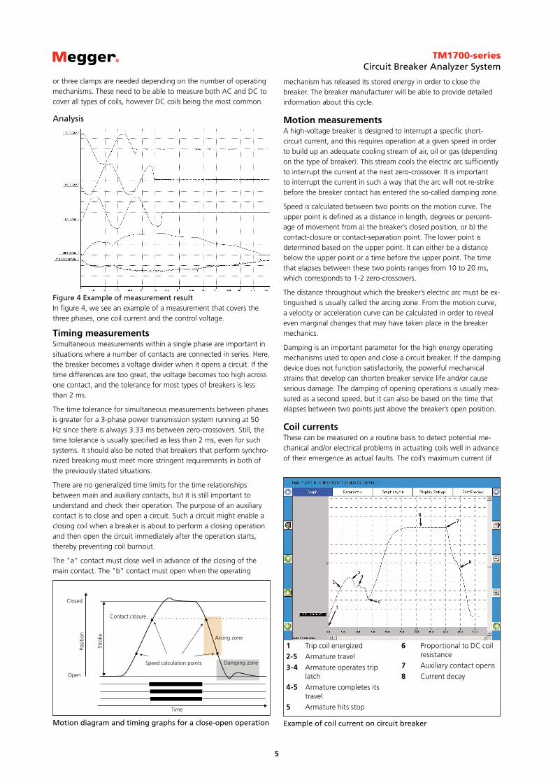
Coil currentsThese can be measured on a routine basis to detect potential me-chanical and/or electrical problems in actuating coils well in advance of their emergence as actual faults. The coil’s maximum current (if
1 Trip coil energized
2-5 Armature travel
3-4 Armature operates trip latch
4-5 Armature completes its travel
5 Armature hits stop
6 Proportional to DC coil resistance
7 Auxiliary contact opens
8 Current decay
Example of coil current on circuit breaker
or three clamps are needed depending on the number of operating mechanisms. These need to be able to measure both AC and DC to cover all types of coils, however DC coils being the most common.
Analysis
Figure 4 Example of measurement resultIn figure 4, we see an example of a measurement that covers the three phases, one coil current and the control voltage.
TM1700-seriesCircuit Breaker Analyzer System
6
current is permitted to reach its highest value) is a direct function of the coil’s resistance and actuating voltage. This test indicates whether or not a winding has been short-circuited.
When you apply a voltage across a coil, the current curve first shows a straight transition whose rate of rise depends on the coil’s electri-cal characteristic and the supply voltage (points 1-2). When the coil armature (which actuates the latch on the operating mechanism’s energy package) starts to move, the electrical relationship changes and the coil current drops (points 3-5). When the armature hits its mechanical end position, the coil current rises to the current pro-portional to the coil voltage (points 5-7). The auxiliary contact then opens the circuit and the coil current drops to zero with a current decay caused by the inductance in the circuit (points 7-8).
The peak value, of the first lower current peak, is related to the fully saturated coil current (max current), and this relationship gives an indication of the spread to the lowest tripping voltage. If the coil was to reach its maximum current before the armature and latch start to move, the breaker would not be tripped. It is important to note, however, that the relationship between the two current peaks varies, particularly with temperature. This also applies to the lowest tripping voltage.
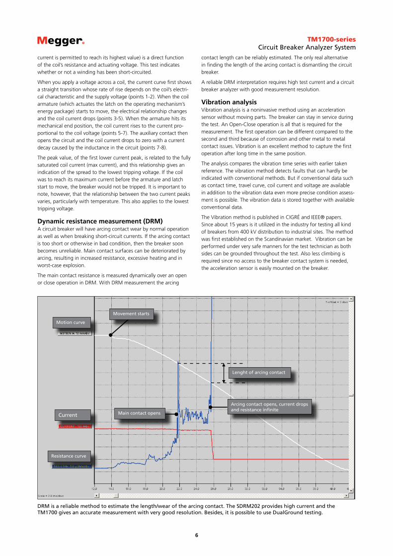
Dynamic resistance measurement (DRM)A circuit breaker will have arcing contact wear by normal operation as well as when breaking short-circuit currents. If the arcing contact is too short or otherwise in bad condition, then the breaker soon becomes unreliable. Main contact surfaces can be deteriorated by arcing, resulting in increased resistance, excessive heating and in worst-case explosion.
The main contact resistance is measured dynamically over an open or close operation in DRM. With DRM measurement the arcing
contact length can be reliably estimated. The only real alternative in finding the length of the arcing contact is dismantling the circuit breaker.
A reliable DRM interpretation requires high test current and a circuit breaker analyzer with good measurement resolution.
Vibration analysisVibration analysis is a noninvasive method using an acceleration sensor without moving parts. The breaker can stay in service during the test. An Open-Close operation is all that is required for the measurement. The first operation can be different compared to the second and third because of corrosion and other metal to metal contact issues. Vibration is an excellent method to capture the first operation after long time in the same position.
The analysis compares the vibration time series with earlier taken reference. The vibration method detects faults that can hardly be indicated with conventional methods. But if conventional data such as contact time, travel curve, coil current and voltage are available in addition to the vibration data even more precise condition assess-ment is possible. The vibration data is stored together with available conventional data.
The Vibration method is published in CIGRÉ and IEEE® papers. Since about 15 years is it utilized in the industry for testing all kind of breakers from 400 kV distribution to industrial sites. The method was first established on the Scandinavian market. Vibration can be performed under very safe manners for the test technician as both sides can be grounded throughout the test. Also less climbing is required since no access to the breaker contact system is needed, the acceleration sensor is easily mounted on the breaker.
Movement starts
Motion curve
Current
Resistance curve
Main contact opens
Lenght of arcing contact
Arcing contact opens, current drops and resistance infinite
DRM is a reliable method to estimate the length/wear of the arcing contact. The SDRM202 provides high current and the TM1700 gives an accurate measurement with very good resolution. Besides, it is possible to use DualGround testing.
TM1700-seriesCircuit Breaker Analyzer System
7
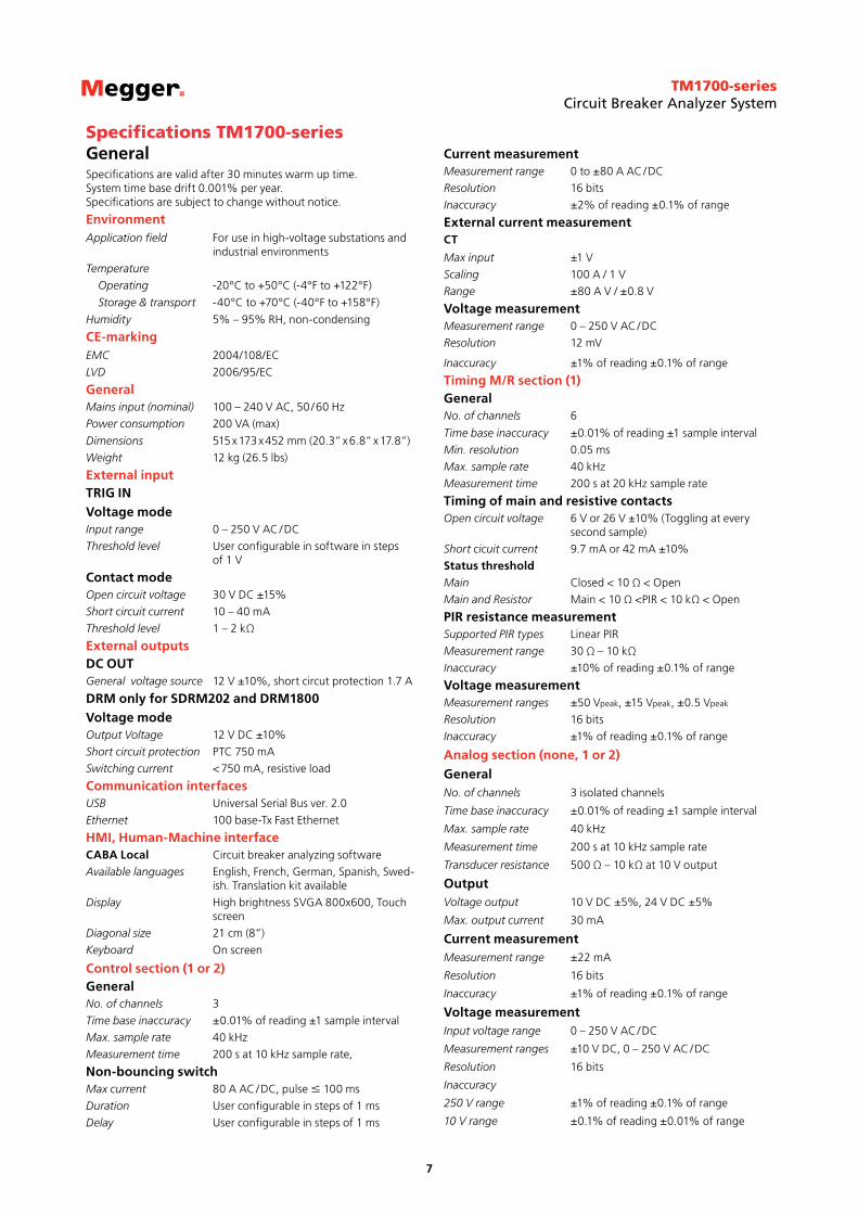
Specifications TM1700-seriesGeneralSpecifications are valid after 30 minutes warm up time. System time base drift 0.001% per year. Specifications are subject to change without notice.
EnvironmentApplication field For use in high-voltage substations and
industrial environments
Temperature
Operating -20°C to +50°C (-4°F to +122°F)
Storage & transport -40°C to +70°C (-40°F to +158°F)
Humidity 5% – 95% RH, non-condensing
CE-markingEMC 2004/108/EC
LVD 2006/95/EC
GeneralMains input (nominal) 100 – 240 V AC, 50 / 60 Hz
Power consumption 200 VA (max)
Dimensions 515 x 173 x 452 mm (20.3” x 6.8” x 17.8”)
Weight 12 kg (26.5 lbs)
External inputTRIG INVoltage modeInput range 0 – 250 V AC / DC
Threshold level User configurable in software in steps of 1 V
Contact modeOpen circuit voltage 30 V DC ±15%
Short circuit current 10 – 40 mA
Threshold level 1 – 2 kΩ
External outputsDC OUTGeneral voltage source 12 V ±10%, short circut protection 1.7 A
DRM only for SDRM202 and DRM1800Voltage modeOutput Voltage 12 V DC ±10%
Short circuit protection PTC 750 mA
Switching current < 750 mA, resistive load
Communication interfacesUSB Universal Serial Bus ver. 2.0
Ethernet 100 base-Tx Fast Ethernet
HMI, Human-Machine interface CABA Local Circuit breaker analyzing software
Available languages English, French, German, Spanish, Swed-ish. Translation kit available
Display High brightness SVGA 800x600, Touch screen
Diagonal size 21 cm (8”)
Keyboard On screen
Control section (1 or 2)GeneralNo. of channels 3
Time base inaccuracy ±0.01% of reading ±1 sample interval
Max. sample rate 40 kHz
Measurement time 200 s at 10 kHz sample rate,
Non-bouncing switchMax current 80 A AC / DC, pulse ≤ 100 ms
Duration User configurable in steps of 1 ms
Delay User configurable in steps of 1 ms
Current measurementMeasurement range 0 to ±80 A AC / DC
Resolution 16 bits
Inaccuracy ±2% of reading ±0.1% of range
External current measurementCT
Max input ±1 V
Scaling 100 A / 1 V
Range ±80 A V / ±0.8 V
Voltage measurementMeasurement range 0 – 250 V AC / DC
Resolution 12 mV
Inaccuracy ±1% of reading ±0.1% of range
Timing M/R section (1)GeneralNo. of channels 6
Time base inaccuracy ±0.01% of reading ±1 sample interval
Min. resolution 0.05 ms
Max. sample rate 40 kHz
Measurement time 200 s at 20 kHz sample rate
Timing of main and resistive contactsOpen circuit voltage 6 V or 26 V ±10% (Toggling at every
second sample)
Short cicuit current 9.7 mA or 42 mA ±10%
Status thresholdMain Closed < 10 Ω < Open
Main and Resistor Main < 10 Ω <PIR < 10 kΩ < Open
PIR resistance measurementSupported PIR types Linear PIR
Measurement range 30 Ω – 10 kΩ
Inaccuracy ±10% of reading ±0.1% of range
Voltage measurementMeasurement ranges ±50 Vpeak, ±15 Vpeak, ±0.5 Vpeak
Resolution 16 bits
Inaccuracy ±1% of reading ±0.1% of range
Analog section (none, 1 or 2)GeneralNo. of channels 3 isolated channels
Time base inaccuracy ±0.01% of reading ±1 sample interval
Max. sample rate 40 kHz
Measurement time 200 s at 10 kHz sample rate
Transducer resistance 500 Ω – 10 kΩ at 10 V output
OutputVoltage output 10 V DC ±5%, 24 V DC ±5%
Max. output current 30 mA
Current measurementMeasurement range ±22 mA
Resolution 16 bits
Inaccuracy ±1% of reading ±0.1% of range
Voltage measurementInput voltage range 0 – 250 V AC / DC
Measurement ranges ±10 V DC, 0 – 250 V AC / DC
Resolution 16 bits
Inaccuracy
250 V range ±1% of reading ±0.1% of range
10 V range ±0.1% of reading ±0.01% of range
TM1700-seriesCircuit Breaker Analyzer System
8
Digital sectionGeneralNo. of channels 6
Supported types Incremental transducers, RS422
Time base inaccuracy ±0.01% of reading ±1 sample interval
Max. sample rate 40 kHz
Measurement time 200 s at 10 kHz sample rate
OutputVoltage 5 V DC ±5% or 12 V DC ±5%
Max. output current 200 mA
Digital inputRange ±32000 pulses
Resolution 1 pulse
Inaccuracy ±1 pulse
Timing Aux sectionGeneralNo. of channels 6 isolated channels
Time base inaccuracy ±0.01% of reading ±1 sample interval
Max. sample rate 40 kHz
Measurement time 200 s at 10 kHz sample rate
Voltage ModeInput voltage range 0 – ±250 V AC / DC
Status threshold ±10 V
Inaccuracy ±0.5 V
Contact modeOpen circuit voltage 25 – 35 V
Short circuit current 10 – 30 mA
Status threshold Closed < 100 Ω, Open > 2 kΩ
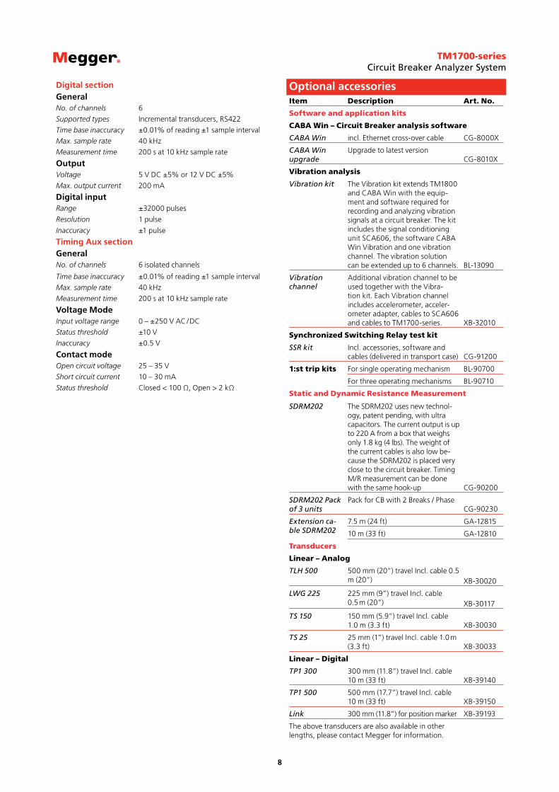
Item Description Art. No.
Software and application kits
CABA Win – Circuit Breaker analysis software
CABA Win incl. Ethernet cross-over cable CG-8000X
CABA Win upgrade
Upgrade to latest versionCG-8010X
Vibration analysis
Vibration kit The Vibration kit extends TM1800 and CABA Win with the equip-ment and software required for recording and analyzing vibration signals at a circuit breaker. The kit includes the signal conditioning unit SCA606, the software CABA Win Vibration and one vibration channel. The vibration solution can be extended up to 6 channels. BL-13090
Vibration channel
Additional vibration channel to be used together with the Vibra-tion kit. Each Vibration channel includes accelerometer, acceler-ometer adapter, cables to SCA606 and cables to TM1700-series. XB-32010
Synchronized Switching Relay test kit
SSR kit Incl. accessories, software and cables (delivered in transport case) CG-91200
1:st trip kits For single operating mechanism BL-90700
For three operating mechanisms BL-90710
Static and Dynamic Resistance Measurement
SDRM202 The SDRM202 uses new technol-ogy, patent pending, with ultra capacitors. The current output is up to 220 A from a box that weighs only 1.8 kg (4 lbs). The weight of the current cables is also low be-cause the SDRM202 is placed very close to the circuit breaker. Timing M/R measurement can be done with the same hook-up CG-90200
SDRM202 Pack of 3 units
Pack for CB with 2 Breaks / PhaseCG-90230
Extension ca-ble SDRM202
7.5 m (24 ft) GA-12815
10 m (33 ft) GA-12810
Transducers
Linear – Analog
TLH 500 500 mm (20”) travel Incl. cable 0.5 m (20”) XB-30020
LWG 225 225 mm (9”) travel Incl. cable 0.5 m (20”) XB-30117
TS 150 150 mm (5.9”) travel Incl. cable 1.0 m (3.3 ft) XB-30030
TS 25 25 mm (1”) travel Incl. cable 1.0 m (3.3 ft) XB-30033
Linear – Digital
TP1 300 300 mm (11.8”) travel Incl. cable 10 m (33 ft) XB-39140
TP1 500 500 mm (17.7”) travel Incl. cable 10 m (33 ft) XB-39150
Link 300 mm (11.8”) for position marker XB-39193
The above transducers are also available in other lengths, please contact Megger for information.
Optional accessories
TM1700-seriesCircuit Breaker Analyzer System
9
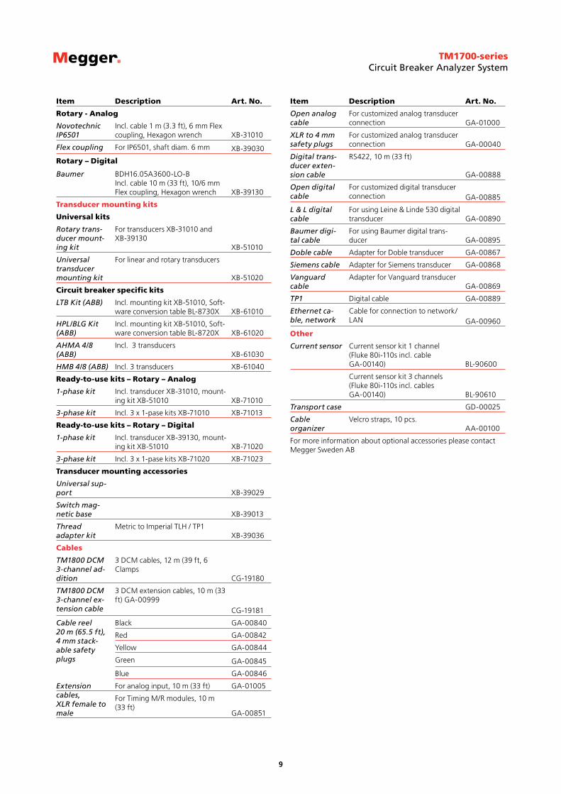
Item Description Art. No.
Rotary - Analog
Novotechnic IP6501
Incl. cable 1 m (3.3 ft), 6 mm Flex coupling, Hexagon wrench XB-31010
Flex coupling For IP6501, shaft diam. 6 mm XB-39030
Rotary – Digital
Baumer BDH16.05A3600-LO-B Incl. cable 10 m (33 ft), 10/6 mm Flex coupling, Hexagon wrench XB-39130
Transducer mounting kits
Universal kits
Rotary trans-ducer mount-ing kit
For transducers XB-31010 and XB-39130
XB-51010
Universal transducer mounting kit
For linear and rotary transducers
XB-51020
Circuit breaker specific kits
LTB Kit (ABB) Incl. mounting kit XB-51010, Soft-ware conversion table BL-8730X XB-61010
HPL/BLG Kit (ABB)
Incl. mounting kit XB-51010, Soft-ware conversion table BL-8720X XB-61020
AHMA 4/8 (ABB)
Incl. 3 transducersXB-61030
HMB 4/8 (ABB) Incl. 3 transducers XB-61040
Ready-to-use kits – Rotary – Analog
1-phase kit Incl. transducer XB-31010, mount-ing kit XB-51010 XB-71010
3-phase kit Incl. 3 x 1-pase kits XB-71010 XB-71013
Ready-to-use kits – Rotary – Digital
1-phase kit Incl. transducer XB-39130, mount-ing kit XB-51010 XB-71020
3-phase kit Incl. 3 x 1-pase kits XB-71020 XB-71023
Transducer mounting accessories
Universal sup-port XB-39029
Switch mag-netic base XB-39013
Thread adapter kit
Metric to Imperial TLH / TP1XB-39036
Cables
TM1800 DCM 3-channel ad-dition
3 DCM cables, 12 m (39 ft, 6 Clamps
CG-19180
TM1800 DCM 3-channel ex-tension cable
3 DCM extension cables, 10 m (33 ft) GA-00999
CG-19181
Cable reel 20 m (65.5 ft), 4 mm stack-able safety plugs
Black GA-00840
Red GA-00842
Yellow GA-00844
Green GA-00845
Blue GA-00846
Extension cables, XLR female to male
For analog input, 10 m (33 ft) GA-01005
For Timing M/R modules, 10 m (33 ft)
GA-00851
Item Description Art. No.
Open analog cable
For customized analog transducer connection GA-01000
XLR to 4 mm safety plugs
For customized analog transducer connection GA-00040
Digital trans-ducer exten-sion cable
RS422, 10 m (33 ft)
GA-00888
Open digital cable
For customized digital transducer connection GA-00885
L & L digital cable
For using Leine & Linde 530 digital transducer GA-00890
Baumer digi-tal cable
For using Baumer digital trans-ducer GA-00895
Doble cable Adapter for Doble transducer GA-00867
Siemens cable Adapter for Siemens transducer GA-00868
Vanguard cable
Adapter for Vanguard transducerGA-00869
TP1 Digital cable GA-00889
Ethernet ca-ble, network
Cable for connection to network/LAN GA-00960
Other
Current sensor Current sensor kit 1 channel (Fluke 80i-110s incl. cable GA-00140) BL-90600
Current sensor kit 3 channels (Fluke 80i-110s incl. cables GA-00140) BL-90610
Transport case GD-00025
Cable organizer
Velcro straps, 10 pcs.AA-00100
For more information about optional accessories please contact Megger Sweden AB
TM1700-seriesCircuit Breaker Analyzer System
10
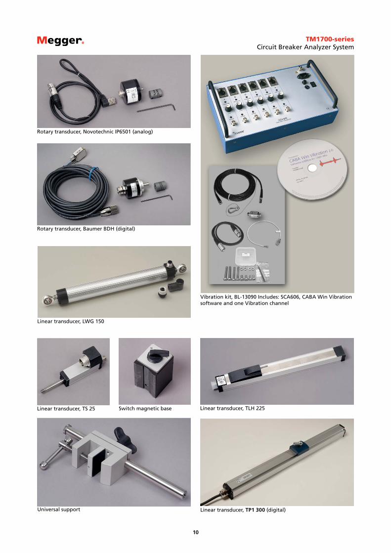
Rotary transducer, Novotechnic IP6501 (analog)
Linear transducer, LWG 150
Linear transducer, TS 25
Rotary transducer, Baumer BDH (digital)
Linear transducer, TLH 225Switch magnetic base
Universal support Linear transducer, TP1 300 (digital)
Vibration kit, BL-13090 Includes: SCA606, CABA Win Vibration software and one Vibration channel
TM1700-seriesCircuit Breaker Analyzer System
11
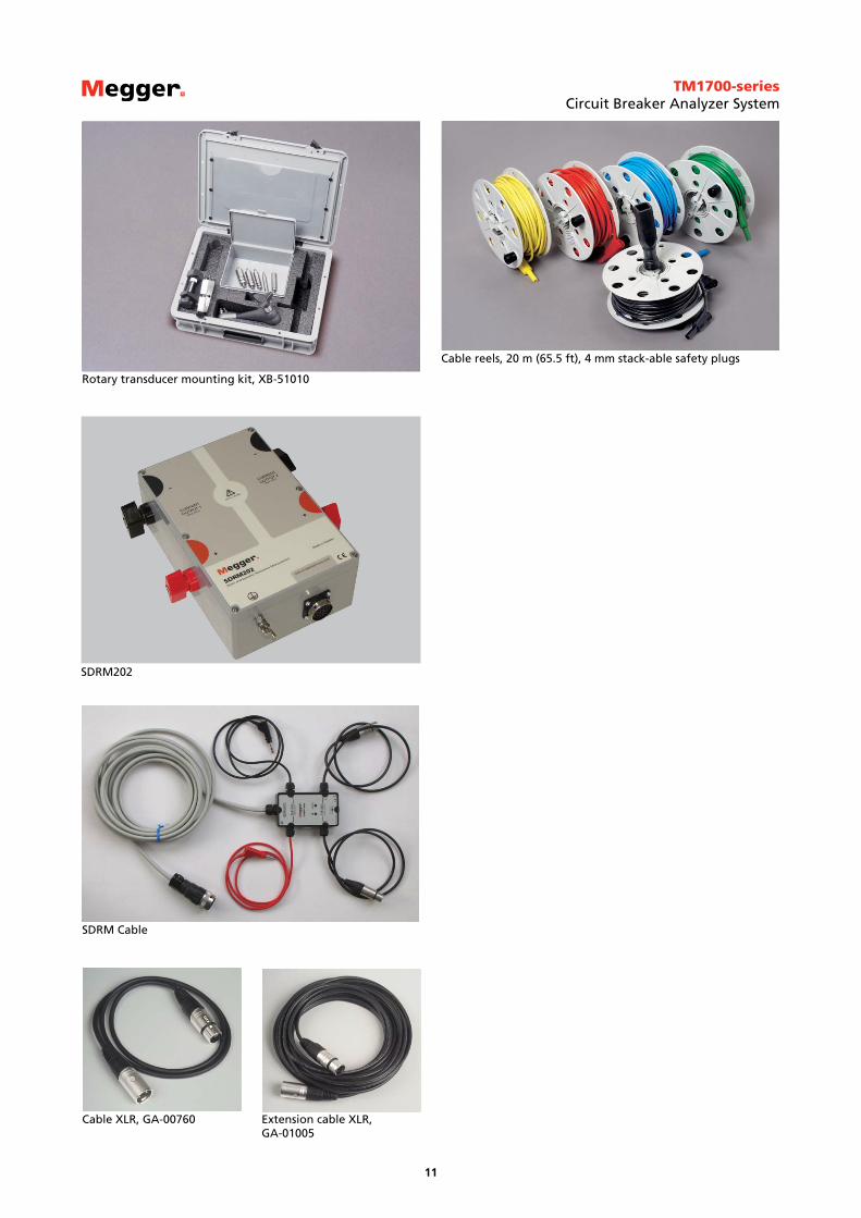
SDRM202
SDRM Cable
Extension cable XLR, GA-01005
Cable XLR, GA-00760
Cable reels, 20 m (65.5 ft), 4 mm stack- able safety plugs
Rotary transducer mounting kit, XB-51010
TM1700-seriesCircuit Breaker Analyzer System
12
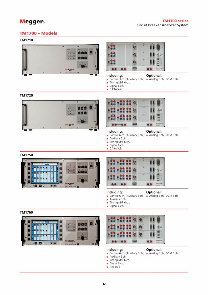
TM1700 – Models
TM1710
Including: Control 3 ch. (Auxiliary 3 ch.) Timing M/R 6 ch. Digital 6 ch. CABA Win
Optional: Analog 3 ch., DCM 6 ch.
TM1720
Including: Control 6 ch. (Auxiliary 6 ch.) Auxiliary 6 ch. Timing M/R 6 ch. Digital 6 ch. CABA Win
Optional: Analog 3 ch., DCM 6 ch.
TM1750
Including: Control 6 ch. (Auxiliary 6 ch.) Auxiliary 6 ch. Timing M/R 6 ch. Digital 6 ch.
Optional: Analog 3 ch., DCM 6 ch.
TM1760
Including: Control 6 ch. (Auxiliary 6 ch.) Auxiliary 6 ch. Timing M/R 6 ch. Digital 6 ch. Analog 3
Optional: Analog 3 ch., DCM 6 ch.
TM1700-seriesCircuit Breaker Analyzer System
SWEDEN Megger Sweden AB Eldarvägen 4, Box 2970 SE-187 29 TÄBY T +46 8 510 195 00 F +46 8 510 195 95 E [email protected]
Other Technical Sales Offices Dallas USA, Norristown USA, Toronto CANADA, Trappes FRANCE, Oberursel GERMANY, Johannesburg SOUTH AFRICA, Kingdom of BAHRAIN Mumbai INDIA, Chonburi THAILAND Sydney AUSTRALIA
UK Archcliffe Road Dover CT17 9EN England T +44 (0) 1304 502101 F +44 (0) 1304 207342
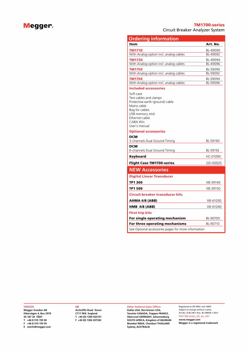
Ordering informationItem Art. No.
TM1710With Analog option incl. analog cables
BL-49090BL-49092
TM1720With Analog option incl. analog cables
BL-49094BL-49096
TM1750With Analog option incl. analog cables
BL-59090BL-59092
TM1760With Analog option incl. analog cables
BL-59094BL-59096
Included accessories
Soft caseTest cables and clampsProtective earth (ground) cableMains cableBag for cablesUSB memory stickEthernet cableCABA WinUser’s manual
Optional accessories
DCM 3-channels Dual Ground Timing BL-59190
DCM6-channels Dual Ground Timing BL-59192
Keyboard HC-01090
Flight Case TM1700-series GD-00025
NEW AccessoriesDigital Linear Transducer
TP1 300 XB-39140
TP1 500 XB-39150
Circuit breaker transducer kits
AHMA 4/8 (ABB) XB-61030
HMB 4/8 (ABB) XB-61040
First trip kits
For single operating mechanism BL-90700
For three operating mechanisms BL-90710
See Optional accessories pages for more information
Registered to ISO 9001 and 14001
Subject to change without notice.
Art.No. ZI-BL14E • Doc. BL1589AE • 2012
TM1700-series_DS_en_V01www.megger.comMegger is a registered trademark