Embed Size (px)
Citation preview

WW
W.M
EG
GER
.CO
M
Circuit breaker analyzer system
Stand-alone functionality – one toolbox for all breaker testing
Expandable modular concept
Safer testing – DualGround™, test circuit breakers with both sides grounded
Designed for off-line and on-line measurement
Rugged and reliable for field use
The complete toolbox for high voltage circuit breaker testing

2 TM1800 Circuit Breaker Analyzer System
TM1800Circuit Breaker Analyzer System
Stand-alone functionality – one toolbox for all breaker testing
Expandable modular concept
Safer testing – DualGround™, test circuit breakers with both sides grounded
Designed for off-line and on-line measurement
Rugged and reliable for field use
DescriptionThe TM1800™ is the instrument platform for circuit breaker maintenance, based on more than 20 years’ experience of over 4,000 delivered breaker analyzers. The modular construction makes it possible to configure the TM1800 for measurements on all known types of circuit breakers in operation on the world market.
The robust design contains powerful technology that streamlines circuit breaker testing. Sophisticated measurement modules enable great time savings as many parameters can be measured simultane-ously, eliminating the need for new setup each time.
The patented DualGround™ testing using the new DCM module makes the testing safe and time saving, by keeping the circuit breaker grounded on both sides throughout the test. The DCM module uses a measuring technology called Dynamic Capacitive Measurement.
Timing M/R is using the patented Active Interference Suppression to obtain correct timing and accurate PIR (Pre-Insertion Resistor) values in high voltage substations.
An adaptive, easy-to-use software suite supports activities from timing, simply turning a knob without the need for presetting, to advanced help functions for hooking up to the test object. A full keyboard and 8” color screen is the front end of the high-level user interface. The Select-Connect-Inspect workflow guides you to fast results in three steps. Testing is made easier to learn and perform.
The system also offers full connection capability to the local net-work, printers etc.
Testing with DualGroundElectricity deregulation changes the business environment for utili-ties, switchgear owners and service companies. Deregulation has been shown to lead directly to increased emphasis on efficiency of operations, maintenance and service levels. Internationalization of business brings new challenges: substantial investments by global corporations will bring with them sharper or new requirements for increased emphasis on health, safety and environmental compli-ance. Experience has also shown demands for shorter time periods for testing, while the switchgear is less and less available to be taken out of service.
The safety aspectNetwork operators and service companies need to maintain and develop their industry safety record. Eminent International bod-ies including the IEEE® and IEC®, National Safety agencies and Trade Unions increases the demands on safety. During the deregulation applicable safety regulations have been clarified and the application of existing rules has tightened. Keeping a good safety record is becoming a crucial asset in attracting investors and customers.
In all substations the capacitive coupling from live high voltage conductors induce harmful/lethal currents in all parallel conduc-tors. Grounding both sides of the test object will lead the induced current to earth and provide a safe area for the test personnel. See figures below.
Both sides groundedThe best way to provide safety in circuit breaker testing is to keep both sides of the circuit breaker grounded throughout the test. This will also make the test faster and easier.
Minimum time shall be spent in the substation and focus shall be on the test rather than the equipment.
The DualGround™ testing method is available for all tests on all circuit breakers.

TM1800 Circuit Breaker Analyzer System 3
With only one side grounded the induced current can reach values high enough to be harmful or lethal for humans.
Testing is much safer using the DCM module and DualGround.
The basic unit is only equipped with the HDD module. Add modules to the configuration that supports your needs.
Equipment and methods that support DualGround™ testing are associated with the DualGround symbol. This symbol certifies the use of ground-breaking technology and methods that enable a safe, fast and easy workflow with both sides grounded throughout the test.
Basic unitThe modularized design makes it very flexible to user needs and enables reconfiguration for new demands and upgrade with new functionality. You can configure TM1800 to a complete test set tailor made for your specific needs. The firmware, CABA Local, guides you to efficient circuit breaker testing.
All inputs and outputs on the TM1800 and the modules are de-signed to withstand the harsh environment in high-voltage substa-tions and industrial environments.
With built-in protection circuits and software-designed protec-tion the TM1800 has a good guard to influences and even failures caused by over-voltages generated in the environment.
The HDD module is a part of the basic unit and contains the hard drive with all data and software setup. It can easily be removed and changed.
Eight user configurable slots for modules
Temperature sensor connection
Trig inputs and outputs
Outputs for warning signal and DRM
Earth (Ground) connection
Communication interfaces (USB, Ethernet, etc)
Contact resistance MJÖLNER / SDRM202
Timing TM1800 with DCM
Motion TM1800
DRM TM1800 with SDRM202
Vibration CABA Win Vibration / SCA606
Conventional vs. DualGroundSite preparation (isolate work area, apply safety ground, issue permit to work)
Site preparation (isolate work area, apply safety ground, issue permit to work)
Hook up test equipment. Issue sanction for test
Hook up test equipment. Issue sanction for test
Authorised person removes the ground
Risky step left out
Perform testing Safe testing with both sides grounded
Authorised person applies ground
Risky step left out
Cancel sanction for test. Disconnect test equipment
Cancel sanction for test. Disconnect test equipment
Site closing (cancel permit to work, disconnect ground)
Site closing (cancel permit to work, disconnect ground)
4 TM1800 Circuit Breaker Analyzer System
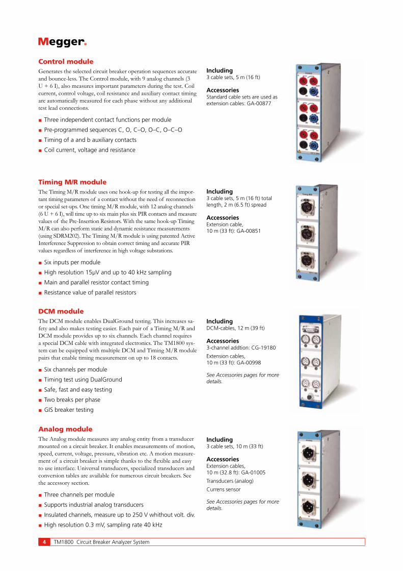
Analog moduleThe Analog module measures any analog entity from a transducer mounted on a circuit breaker. It enables measurements of motion, speed, current, voltage, pressure, vibration etc. A motion measure-ment of a circuit breaker is simple thanks to the flexible and easy to use interface. Universal transducers, specialized transducers and conversion tables are available for numerous circuit breakers. See the accessory section.
Three channels per module
Supports industrial analog transducers
Insulated channels, measure up to 250 V whithout volt. div.
High resolution 0.3 mV, sampling rate 40 kHz
DCM moduleThe DCM module enables DualGround testing. This increases sa-fety and also makes testing easier. Each pair of a Timing M/R and DCM module provides up to six channels. Each channel requires a special DCM cable with integrated electronics. The TM1800 sys-tem can be equipped with multiple DCM and Timing M/R module pairs that enable timing measurement on up to 18 contacts.
Six channels per module
Timing test using DualGround
Safe, fast and easy testing
Two breaks per phase
GIS breaker testing
Timing M/R moduleThe Timing M/R module uses one hook-up for testing all the impor-tant timing parameters of a contact without the need of reconnection or special set-ups. One timing M/R module, with 12 analog channels (6 U + 6 I), will time up to six main plus six PIR contacts and measure values of the Pre-Insertion Resistors. With the same hook-up Timing M/R can also perform static and dynamic resistance measurements (using SDRM202). The Timing M/R module is using patented Active Interference Suppression to obtain correct timing and accurate PIR values regardless of interference in high voltage substations.
Six inputs per module
High resolution 15μV and up to 40 kHz sampling
Main and parallel resistor contact timing
Resistance value of parallel resistors
Control moduleGenerates the selected circuit breaker operation sequences accurate and bounce-less. The Control module, with 9 analog channels (3 U + 6 I), also measures important parameters during the test. Coil current, control voltage, coil resistance and auxiliary contact timing are automatically measured for each phase without any additional test lead connections.
Three independent contact functions per module
Pre-programmed sequences C, O, C–O, O–C, O–C–O
Timing of a and b auxiliary contacts
Coil current, voltage and resistance
Including3 cable sets, 5 m (16 ft)
AccessoriesStandard cable sets are used as extension cables: GA-00877
Including3 cable sets, 5 m (16 ft) total length, 2 m (6.5 ft) spread
AccessoriesExtension cable, 10 m (33 ft): GA-00851
IncludingDCM-cables, 12 m (39 ft)
Accessories3-channel addtion: CG-19180
Extension cables, 10 m (33 ft): GA-00998
See Accessories pages for more details.
Including3 cable sets, 10 m (33 ft)
AccessoriesExtension cables, 10 m (32.8 ft): GA-01005
Transducers (analog)
Currens sensor
See Accessories pages for more details.
TM1800 Circuit Breaker Analyzer System 5
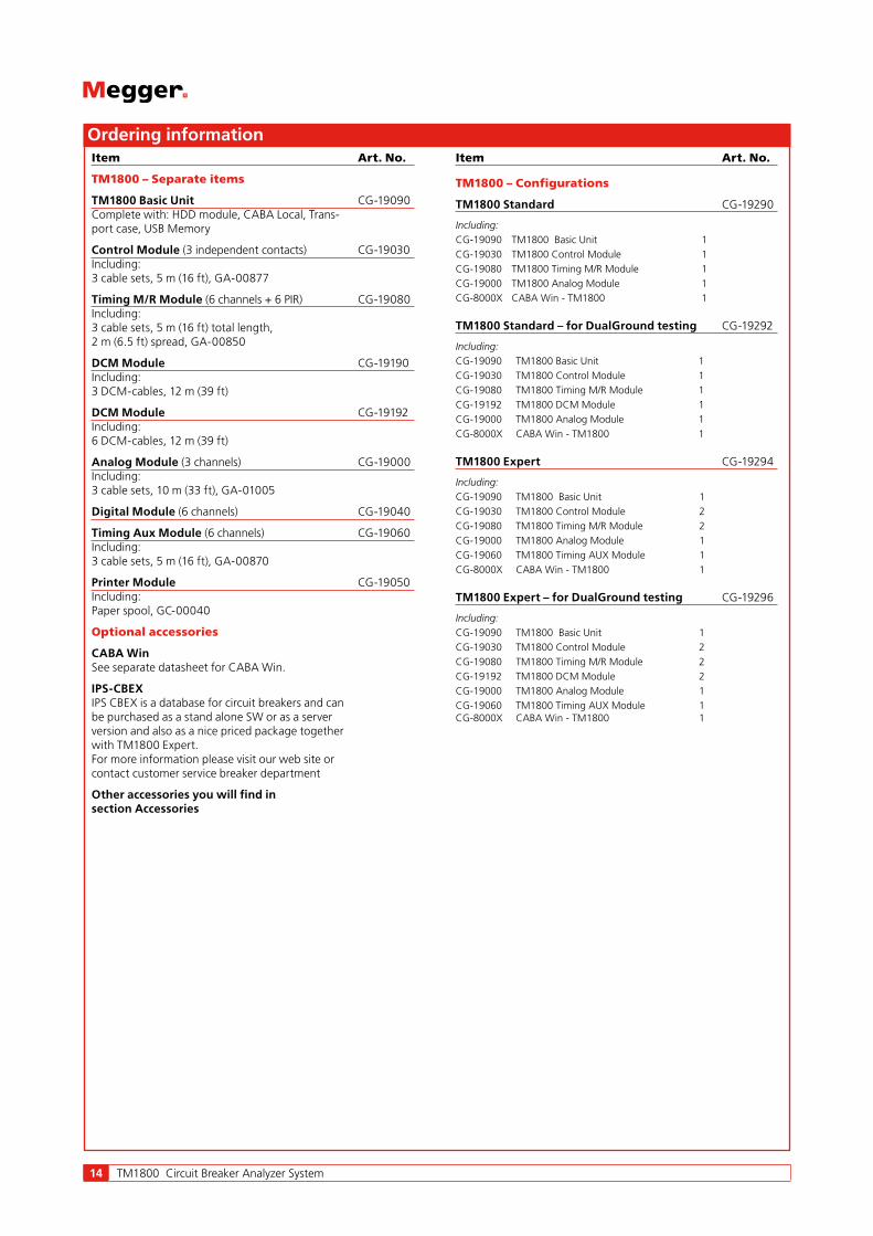
HDD moduleThe HDD module is a part of the Basic unit. Storage of all set-up, user customization and measurement data is done in the HDD module. The module is easily replaced e.g. when different users are sharing one TM1800 and want individual setups, data and configu-rations.
Change set-up, user customization, measurement data by changing HDD module
Easy to remove during transportation
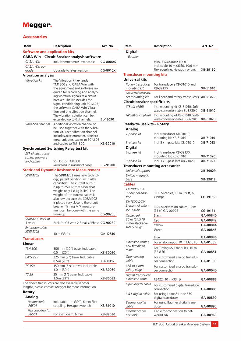
Printer moduleThe Printer module offers a convenient and practical way of making printouts of test results in the field. The printouts contain both numerical and graphical results and printer templates delive-red pre-installed in the TM1800 are easy to adapt to suit specific needs for a clear and complete report of all tested parameters.
Thermal printer sensitive line dot method
Paper width 114 mm (4")
Printing speed 50 mm/s (400 dot lines/s)
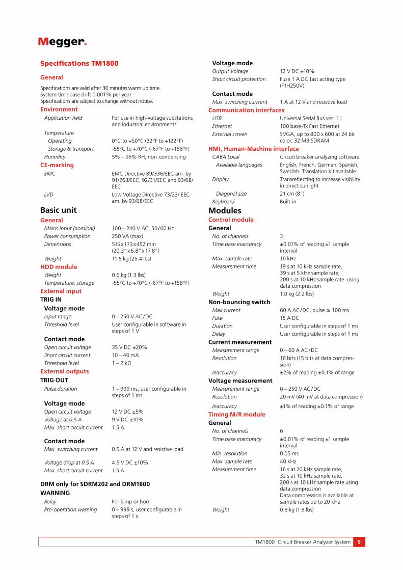
Timing Aux moduleExpands the TM1800 system with timing inputs for measuring any auxiliary contact on the circuit breaker. It measures timing, polarity insensitive, of both dry and wet contacts for example timing of spring charging motor, anti-pump relay etc.
Six channels per module
Polarity insensitive
Dry and wet auxiliary contacts
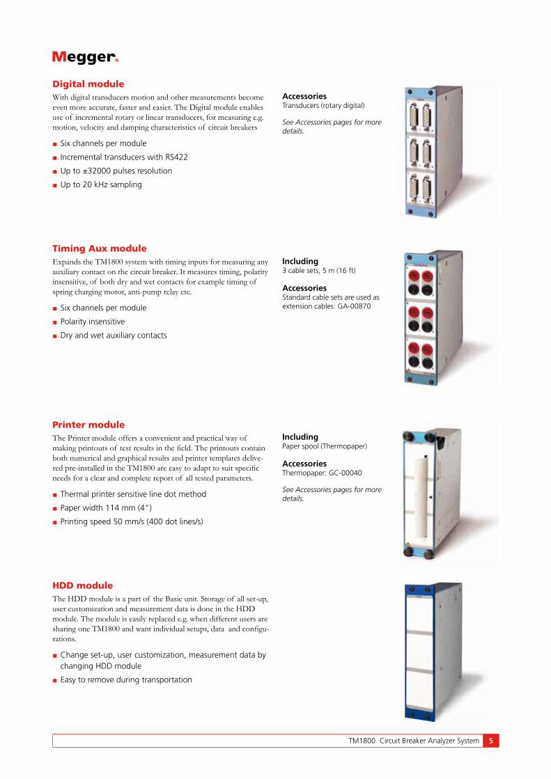
Digital moduleWith digital transducers motion and other measurements become even more accurate, faster and easier. The Digital module enables use of incremental rotary or linear transducers, for measuring e.g. motion, velocity and damping characteristics of circuit breakers
Six channels per module
Incremental transducers with RS422
Up to ±32000 pulses resolution
Up to 20 kHz sampling
AccessoriesTransducers (rotary digital)
See Accessories pages for more details.
Including3 cable sets, 5 m (16 ft)
AccessoriesStandard cable sets are used as extension cables: GA-00870
IncludingPaper spool (Thermopaper)
AccessoriesThermopaper: GC-00040
See Accessories pages for more details.

6 TM1800 Circuit Breaker Analyzer System
1 Trip coil energized2-5 Armature travel3-4 Armature operates
trip latch4-5 Armature completes
its travel5 Armature hits stop
6 Proportional to DC coil resistance
7 Auxiliary contact opens
8 Current decay
Time
Open
Speed calculation points Damping zone
Arcing zone
Contact closure
Closed
Stro
ke
Posi
tion
Application
Timing measurementsSimultaneous measurements within a single phase are important in situations where a number of contacts are connected in series. Here, the breaker becomes a voltage divider when it opens a circuit. If the time differences are too great, the voltage becomes too high across one contact, and the tolerance for most types of breakers is less than 2 ms.
The time tolerance for simultaneous measurements between phas-es is greater for a 3-phase power transmission system running at 50 Hz since there is always 3.33 ms between zero-crossovers. Still, the time tolerance is usually specified as less than 2 ms, even for such systems. It should also be noted that breakers that perform synchronized breaking must meet more stringent requirements in both of the previously stated situations.
There are no generalized time limits for the time relationships between main and auxiliary contacts, but it is still important to understand and check their operation. The purpose of an auxiliary contact is to close and open a circuit. Such a circuit might enable a closing coil when a breaker is about to perform a closing operation and then open the circuit immediately after the operation starts, thereby preventing coil burnout.
The "a" contact must close well in advance of the closing of the main contact. The "b" contact must open when the operating mechanism has released its stored energy in order to close the breaker. The breaker manufacturer will be able to provide detailed information about this cycle.
Motion measurementsA high-voltage breaker is designed to interrupt a specific short-circuit current, and this requires operation at a given speed in order to build up an adequate cooling stream of air, oil or gas (depend-ing on the type of breaker). This stream cools the electric arc sufficiently to interrupt the current at the next zero-crossover. It is important to interrupt the current in such a way that the arc will not re-strike before the breaker contact has entered the so-called damping zone.
Speed is calculated between two points on the motion curve. The upper point is defined as a distance in length, degrees or percent-age of movement from a) the breaker’s closed position, or b) the contact-closure or contact-separation point. The time that elapses between these two points ranges from 10 to 20 ms, which cor-responds to 1-2 zero-crossovers.
The distance throughout which the breaker’s electric arc must be extinguished is usually called the arcing zone. From the motion
curve, a velocity or acceleration curve can be calculated in order to reveal even marginal changes that may have taken place in the breaker mechanics.
Damping is an important parameter for the high energy operating mechanisms used to open and close a circuit breaker. If the damp-ing device does not function satisfactorily, the powerful mechanical strains that develop can shorten breaker service life and/or cause serious damage. The damping of opening operations is usually measured as a second speed, but it can also be based on the time that elapses between two points just above the breaker’s open position.
Coil currentsThese can be measured on a routine basis to detect potential mechanical and/or electrical problems in actuating coils well in advance of their emergence as actual faults. The coil’s maximum current (if current is permitted to reach its highest value) is a direct function of the coil’s resistance and actuating voltage. This test indicates whether or not a winding has been short-circuited.
When you apply a voltage across a coil, the current curve first shows a straight transition whose rate of rise depends on the coil’s electrical characteristic and the supply voltage (points 1-2). When the coil armature (which actuates the latch on the operat-ing mechanism’s energy package) starts to move, the electrical relationship changes and the coil current drops (points 3-5). When the armature hits its mechanical end position, the coil current rises to the current proportional to the coil voltage (points 5-7). The auxiliary contact then opens the circuit and the coil current drops to zero with a current decay caused by the inductance in the circuit (points 7-8).
The peak value, of the first lower current peak, is related to the fully saturated coil current (max current), and this relationship gives an indication of the spread to the lowest tripping voltage. If the coil was to reach its maximum current before the armature and latch start to move, the breaker would not be tripped. It is important to note, however, that the relationship between the two
Motion diagram and timing graphs for a close-open operationExample of coil current on circuit breaker

TM1800 Circuit Breaker Analyzer System 7
Movement starts
Motion curve
Current
Resistance curve
Main contact opens
Lenght of arcing contact
Arcing contact opens, current drops and resistance infinite
current peaks varies, particularly with temperature. This also ap-plies to the lowest tripping voltage.
Dynamic resistance measurement (DRM)A circuit breaker will have arcing contact wear by normal operation as well as when breaking short-circuit currents. If the arcing con-tact is too short or otherwise in bad condition, then the breaker soon becomes unreliable. Main contact surfaces can be deterio-rated by arching, resulting in increased resistance, excessive heating and in worst-case explosion.
The main contact resistance is measured dynamically over an open or close operation in DRM. With DRM measurement the arcing contact length can be reliably estimated. The only real alternative in finding the length of the arcing contact is dismantling the circuit breaker.
A reliable DRM interpretation requires high test current and a circuit breaker analyzer with good measurement resolution.
Vibration analysisVibration analysis is a noninvasive method using an acceleration sensor without moving parts. The breaker can stay in service dur-ing the test. An Open-Close operation is all that is required for the measurement. The first operation can be different compared to the second and third because of corrosion and other metal to metal contact issues. Vibration is an excellent method to capture the first operation after long time in the same position.
The analysis compares the vibration time series with earlier taken reference. The vibration method detects faults that can hardly be indicated with conventional methods. But if conventional data
such as contact time, travel curve, coil current and voltage are available in addition to the vibration data even more precise condi-tion assessment is possible. The vibration data is stored together with available conventional data.
The Vibration method is published in CIGRÉ and IEEE® papers. Since about 15 years is it utilized in the industry for testing all kind of breakers from 400 kV distribution to industrial sites. The meth-od was first established on the Scandinavian market. Vibration can be performed under very safe manners for the test technician as both sides can be grounded throughout the test. Also less climbing is required since no access to the breaker contact system is needed, the acceleration sensor is easily mounted on the breaker.
DRM is a reliable method to estimate the length/wear of the arcing contact. The SDRM202 provides high current and the TM1800 gives an accurate measurement with very good resolution. Besides, it is possible to use DualGround testing.

8 TM1800 Circuit Breaker Analyzer System
Select – Connect – InspectWorking with TM1800 means fast and easy testing. Testing is done with a three-step process.
First step is to select a suitable template from the template library depending on number of contacts per phase, motion or not, resis-tor contacts and more.
Second step is to connect the test leads according to the graphical help screen.
Third step is to turn the “Measure” knob. The measurement is performed, analyzed and the results will be displayed on the screen. Magnification and compare functions are available.
For more advanced setup there is still the opportunity to control all the details in the measurement. The large number of general purpose templates cover most circuit breakers found around the world. It is also possible to select a tailor made template with special adaptions. You can edit templates yourself or with assis-tance from our customer support. This is a very powerful tool to customize TM1800 for fast and easy work according to your needs in every detail. Increase the level of detail as you learn.
After the test it is possible to print a test report, either from the TM1800 printer module or using CABA Win on a PC. With CABA Win you can make a more advanced analysis of the data. CABA Win is also the archive for common test data and interface to CBEX. With CBEX the test is stored in a database.
Application examples
6 Timing and 3 MotionCircuit breaker: Any CB with two contacts per phase
and separate drives
TM1800 configuration: TM1800 Expert
1 Select breaker template: Generic templates / 2 breaks per phase / Separate drives / Two Control modules / No resistor contact / Motion
2 Connect cables according to "Analyzer view" in CABA Local. Turn the OPERATE/MEASURE knob.
3 Inspect the result on screen.
Note:Coil current and auxiliary contacts are measured and displayed automatically.
If TM1800 is configured with a DCM module the test can be made using DualGround.
SelectSelect the template suitable for the test and circuit breaker from the library.
ConnectConnect test leads and cables according to display. Separate help screen per cable.
InspectTurn the knob and the measurement is displayed on the screen ready for inspection.
TM1800 Circuit Breaker Analyzer System 9
Specifications TM1800
General
Specifications are valid after 30 minutes warm up time. System time base drift 0.001% per year. Specifications are subject to change without notice.
EnvironmentApplication field For use in high-voltage substations
and industrial environments
Temperature
Operating 0°C to +50°C (32°F to +122°F)
Storage & transport -55°C to +70°C (-67°F to +158°F)
Humidity 5% – 95% RH, non-condensing
CE-markingEMC EMC Directive 89/336/EEC am. by
91/263/EEC, 92/31/EEC and 93/68/EEC
LVD Low Voltage Directive 73/23/ EEC am. by 93/68/EEC
Basic unitGeneral
Mains input (nominal) 100 – 240 V AC, 50 / 60 Hz
Power consumption 250 VA (max)
Dimensions 515 x 173 x 452 mm (20.3” x 6.8” x 17.8”)
Weight 11.5 kg (25.4 lbs)
HDD moduleWeight 0.6 kg (1.3 lbs)
Temperature, storage -55°C to +70°C (-67°F to +158°F)
External inputTRIG IN
Voltage modeInput range 0 – 250 V AC / DC
Threshold level User configurable in software in steps of 1 V
Contact modeOpen circuit voltage 35 V DC ±20%
Short circuit current 10 – 40 mA
Threshold level 1 – 2 kΩ
External outputsTRIG OUT
Pulse duration 1 – 999 ms, user configurable in steps of 1 ms
Voltage modeOpen circuit voltage 12 V DC ±5%
Voltage at 0.5 A 9 V DC ±10%
Max. short circuit current 1.5 A
Contact modeMax. switching current 0.5 A at 12 V and resistive load
Voltage drop at 0.5 A 4.5 V DC ±10%
Max. short circuit current 1.5 A
DRM only for SDRM202 and DRM1800WARNING
Relay For lamp or horn
Pre-operation warning 0 – 999 s, user configurable in steps of 1 s
Voltage modeOutput Voltage 12 V DC ±10%
Short circuit protection Fuse 1 A DC fast acting type (F1H250V)
Contact modeMax. switching currrent 1 A at 12 V and resistive load
Communication interfacesUSB Universal Serial Bus ver. 1.1
Ethernet 100 base-Tx Fast Ethernet
External screen SVGA, up to 800 x 600 at 24 bit color, 32 MB SDRAM
HMI, Human-Machine interface CABA Local Circuit breaker analyzing software
Available languages English, French, German, Spanish, Swedish. Translation kit available
Display Transreflecting to increase visibility in direct sunlight
Diagonal size 21 cm (8”)
Keyboard Built-in
ModulesControl moduleGeneral
No. of channels 3
Time base inaccuracy ±0.01% of reading ±1 sample interval
Max. sample rate 10 kHz
Measurement time 19 s at 10 kHz sample rate, 39 s at 5 kHz sample rate, 200 s at 10 kHz sample rate using data compression
Weight 1.0 kg (2.2 lbs)
Non-bouncing switchMax current 60 A AC / DC, pulse ≤ 100 ms
Fuse 15 A DC
Duration User configurable in steps of 1 ms
Delay User configurable in steps of 1 ms
Current measurementMeasurement range 0 – 60 A AC / DC
Resolution 16 bits (15 bits at data compres-sion)
Inaccuracy ±2% of reading ±0.1% of range
Voltage measurementMeasurement range 0 – 250 V AC / DC
Resolution 20 mV (40 mV at data compression)
Inaccuracy ±1% of reading ±0.1% of range
Timing M/R moduleGeneral
No. of channels 6
Time base inaccuracy ±0.01% of reading ±1 sample interval
Min. resolution 0.05 ms
Max. sample rate 40 kHz
Measurement time 16 s at 20 kHz sample rate, 32 s at 10 kHz sample rate, 200 s at 10 kHz sample rate using data compression Data compression is available at sample rates up to 20 kHz
Weight 0.8 kg (1.8 lbs)

10 TM1800 Circuit Breaker Analyzer System
Timing of main and resistive contactsOpen circuit voltage 6 V or 26 V ±10% (Toggling at
every second sample at sample rates from 10 kHz and upwards.)
Short cicuit current 9.7 mA or 42 mA ±10%
Status threshold
Main Closed < 10 Ω < Open
Main and Resistor Main < 10 Ω <PIR < 10 kΩ < Open
PIR resistance measurementSupported PIR types Linear PIR
Measurement range 10 Ω – 10 kΩ
Inaccuracy ±10% of reading ±0.1% of range
Voltage measurementMeasurement ranges ±50 Vpeak, ±15 Vpeak, ±0.5 Vpeak
Resolution 16 bits
Inaccuracy ±1% of reading ±0.1% of range
DCM moduleGeneral
No. of channels 6
Weight 0.6 kg (1.3 lbs)
OutputVoltage 0 - 5 V rms AC
Current 0 - 70 mA rms AC
Analog moduleGeneral
No. of channels 3
Time base inaccuracy ±0.01% of reading ±1 sample interval
Max. sample rate 40 kHz
Measurement time 10 s at 40 kHz sample rate, 20 s at 20 kHz sample rate, 200 s at 10 kHz sample rate using data compression
Transducer resistance 500 Ω – 10 kΩ at 10 V output
Weight 0.8 kg (1.8 lbs)
OutputVoltage output 10 V DC ±5%, 24 V DC ±5%
Max. output current 30 mA
Current measurementMeasurement range 0 – 20 mA DC
Resolution 16 bits (15 bits at data compres-sion)
Inaccuracy ±1% of reading ±0.1% of range
Voltage measurementInput voltage range 0 – 250 V AC / DC
Measurement ranges ±10 V DC, 0 – 250 V AC / DC
Resolution 16 bits (15 bits at data compres-sion)
Inaccuracy
250 V range ±1% of reading ±0.1% of range
10 V range ±0.1% of reading ±0.01% of range
Digital moduleGeneral
No. of channels 6
Supported types Incremental transducers, RS422
Time base inaccuracy ±0.01% of reading ±1 sample interval
Max. sample rate 20 kHz
Measurement time 16 s at 20 kHz sample rate, 32 s at 10 kHz sample rate, 200 s at 10 kHz sample rate using data compression
Weight 0.7 kg (1.5 lbs)
OutputVoltage 5 V DC ±5% or 12 V DC ±5%
Max. output current 200 mA
Digital inputRange ±32000 pulses
Resolution 1 pulse
Inaccuracy ±1 pulse
Timing Aux moduleGeneral
No. of channels 6
Time base inaccuracy ±0.01% of reading ±1 sample interval
Max. sample rate 20 kHz
Measurement time 15 s at 20 kHz sample rate, 30 s at 10 kHz sample rate, 200 s at 10 kHz sample rate using data compression
Weight 0.8 kg (1.8 lbs)
Voltage ModeInput voltage range 0 – ±250 V AC / DC
Status threshold ±10 V
Inaccuracy ±0.5 V
Contact modeOpen circuit voltage 25 – 35 V
Short circuit current 10 – 30 mA
Status threshold Closed < 100 Ω, Open > 2 kΩ
Printer moduleGeneral
Printer type Thermal printer
Paper type Thermal 114 mm
Storage and transport temperature
-20°C to +60°C (-4°F to +140°F)
Weight 0.8 kg (1.8 lbs)
TM1800 Circuit Breaker Analyzer System 11
Item Description Art. No.
Software and application kitsCABA Win – Circuit Breaker analysis software
CABA Win incl. Ethernet cross-over cable CG-8000XCABA Win up-grade Upgrade to latest version CG-8010X
Vibration analysisVibration kit The Vibration kit extends
TM1800 and CABA Win with the equipment and software re-quired for recording and analyz-ing vibration signals at a circuit breaker. The kit includes the signal conditioning unit SCA606, the software CABA Win Vibra-tion and one vibration channel. The vibration solution can be extended up to 6 channels. BL-13090
Vibration channel Additional vibration channel to be used together with the Vibra-tion kit. Each Vibration channel includes accelerometer, accelero-meter adapter, cables to SCA606 and cables to TM1800. XB-32010
Synchronized Switching Relay test kitSSR kit incl. acces-sories, software and cables SSR kit for TM1800
(delivered in transport case) CG-91200
Static and Dynamic Resistance MeasurementSDRM202 The SDRM202 uses new technol-
ogy, patent pending, with ultra capacitors. The current output is up to 250 A from a box that weighs only 1.8 kg (4 lbs). The weight of the current cables is also low because the SDRM202 is placed very close to the circuit breaker. Timing M/R measure-ment can be done with the same hook-up CG-90200
SDRM202 Pack of 3 units Pack for CB with 2 Breaks / Phase CG-90230Extension cable SDRM202
10 m (33 ft) GA-12810
TransducersLinear
TLH 500 500 mm (20”) travel Incl. cable 0.5 m (20”) XB-30020
LWG 225 225 mm (9”) travel Incl. cable 0.5 m (20”) XB-30117
TS 150 150 mm (5.9”) travel Incl. cable 1.0 m (39”) XB-30030
TS 25 25 mm (1”) travel Incl. cable 1.0 m (39”) XB-30033
The above transducers are also available in other lengths, please contact Megger for more information.
RotaryAnalog
Novotechnic IP6501
Incl. cable 1 m (39”), 6 mm Flex coupling, Hexagon wrench XB-31010
Flex coupling for IP6501 For shaft diam. 6 mm XB-39030
Item Description Art. No.
DigitalBaumer
BDH16.05A3600-LO-B Incl. cable 10 m (33ft), 10/6 mm Flex coupling, Hexagon wrench XB-39130
Transducer mounting kitsUniversal kits
Rotary transducer mounting kit
For transducers XB-31010 and XB-39130 XB-51010
Universal transdu-cer mounting kit For linear and rotary transducers XB-51020
Circuit breaker specific kitsLTB Kit (ABB) Incl. mounting kit XB-51010, Soft-
ware conversion table BL-8730X XB-61010HPL/BLG Kit (ABB) Incl. mounting kit XB-51010, Soft-
ware conversion table BL-8720X XB-61020
Ready-to-use kits – RotaryAnalog1-phase kit Incl. transducer XB-31010,
mounting kit XB-51010 XB-710103-phase kit Incl. 3 x 1-pase kits XB-71010 XB-71013
Digital1-phase kit Incl. transducer XB-39130,
mounting kit XB-51010 XB-710203-phase kit Incl. 3 x 1-pase kits XB-71020 XB-71023
Transducer mounting accessoriesUniversal support XB-39029Switch magnetic base XB-39013
CablesTM1800 DCM 3-channel addi-tion
3 DCM cables, 12 m (39 ft, 6 Clamps CG-19180
TM1800 DCM 3-channel exten-sion cable
3 DCM extension cables, 10 m (33 ft) GA-00998 CG-19181
Cable reel 20 m (65.5 ft), 4 mm stackable safety plugs
Black GA-00840
Red GA-00842Yellow GA-00844Green GA-00845
Blue GA-00846Extension cables, XLR female to male
For analog input, 10 m (32.8 ft) GA-01005
For Timing M/R modules, 10 m (32.8 ft) GA-00851
Open analog cable
For customized analog transdu-cer connection GA-01000
XLR to 4 mm safety plugs
For customized analog transdu-cer connection GA-00040
Digital transducer extension cable RS422, 10 m (33 ft) GA-00888Open digital cable For customized digital transducer
connection GA-00885L & L digital cable For using Leine & Linde 530
digital transducer GA-00890Baumer digital cable
For using Baumer digital trans-ducer GA-00895
Ethernet cable, network
Cable for connection to net-work/LAN GA-00960
Accessories

12 TM1800 Circuit Breaker Analyzer System
Rotary transducer, Novotechnic IP6501 (analog)
Linear transducer, LWG 150
Linear transducer, TS 25
Rotary transducer, Baumer BDH (digital)
Linear transducer, TLH 225
SDRM202
SDRM Cable Switch magnetic base
Item Description Art. No.
OtherCurrent sensor Current sensor kit 1 channel
(Fluke 80i-110s incl. cable GA-00140) BL-90600Current sensor kit 3 channels (Fluke 80i-110s incl. cables GA-00140) BL-90610
Temperature sensor
With the temperature sensor the ambient temperature is automatically recorded with each measurement and stored together with the test result. The temperature becomes a parame-ter in CABA Win. The tempe-rature sensor shall be placed in the shade. Suitable cable is the Analog cable, 10 m GA-01005. Range: -20°C to +50°C (-4°F to +122°F), Resolution: 0.5°C (0.9°F) CG-90070
Thermopaper 114 mm, Ø 40 mm GC-00040Soft case Made from sturdy nylon fabric GD-00340Cable organizer Velcro straps, 10 pcs. AA-00100
For more information about optional accessories please contact Megger Sweden AB
Accessories

TM1800 Circuit Breaker Analyzer System 13
Vibration kit, BL-13090 Includes: SCA606, CABA Win Vibra-tion software and one Vibration channel
Extension cable XLR, GA-01005Cable XLR, GA-00760
Soft caseCable reels, 20 m (65.5 ft), 4 mm stack- able safety plugs
Temperature sensor
Rotary transducer mounting kit, XB-51010
Universal support
IPS-CBEX, database
14 TM1800 Circuit Breaker Analyzer System
Item Art. No.
TM1800 – Separate items
TM1800 Basic UnitComplete with: HDD module, CABA Local, Trans-port case, USB Memory
CG-19090
Control Module (3 independent contacts)Including: 3 cable sets, 5 m (16 ft), GA-00877
CG-19030
Timing M/R Module (6 channels + 6 PIR)Including: 3 cable sets, 5 m (16 ft) total length, 2 m (6.5 ft) spread, GA-00850
CG-19080
DCM ModuleIncluding: 3 DCM-cables, 12 m (39 ft)
CG-19190
DCM ModuleIncluding: 6 DCM-cables, 12 m (39 ft)
CG-19192
Analog Module (3 channels)Including: 3 cable sets, 10 m (33 ft), GA-01005
CG-19000
Digital Module (6 channels) CG-19040
Timing Aux Module (6 channels)Including: 3 cable sets, 5 m (16 ft), GA-00870
CG-19060
Printer ModuleIncluding: Paper spool, GC-00040
CG-19050
Optional accessories
CABA WinSee separate datasheet for CABA Win.
IPS-CBEXIPS CBEX is a database for circuit breakers and can be purchased as a stand alone SW or as a server version and also as a nice priced package together with TM1800 Expert.For more information please visit our web site or contact customer service breaker department
Other accessories you will find in section Accessories
Item Art. No.
TM1800 – Configurations
TM1800 Standard CG-19290
Including:CG-19090 TM1800 Basic Unit 1CG-19030 TM1800 Control Module 1CG-19080 TM1800 Timing M/R Module 1CG-19000 TM1800 Analog Module 1CG-8000X CABA Win - TM1800 1
TM1800 Standard – for DualGround testing CG-19292
Including:CG-19090 TM1800 Basic Unit 1CG-19030 TM1800 Control Module 1CG-19080 TM1800 Timing M/R Module 1CG-19192 TM1800 DCM Module 1CG-19000 TM1800 Analog Module 1CG-8000X CABA Win - TM1800 1
TM1800 Expert CG-19294
Including:CG-19090 TM1800 Basic Unit 1CG-19030 TM1800 Control Module 2CG-19080 TM1800 Timing M/R Module 2CG-19000 TM1800 Analog Module 1CG-19060 TM1800 Timing AUX Module 1CG-8000X CABA Win - TM1800 1
TM1800 Expert – for DualGround testing CG-19296
Including:CG-19090 TM1800 Basic Unit 1CG-19030 TM1800 Control Module 2CG-19080 TM1800 Timing M/R Module 2CG-19192 TM1800 DCM Module 2CG-19000 TM1800 Analog Module 1CG-19060 TM1800 Timing AUX Module 1CG-8000X CABA Win - TM1800 1
Ordering information

TM1800 Circuit Breaker Analyzer System 15
TM1800 – Configurations Art. No.
TM1800 Basic UnitCB testing example
No testing is possible. Modules has to be ordered separately.
CG-19090
TM1800 StandardCB testing example
One common operating mechanism
Two breaks per phase
One travel motion
CG-19290
DCM-cables x 6
TM1800 Standard – for DualGroundCB testing example
With both sides grounded
One common operating mechanism
Two breaks per phase
One travel motion
CG-19292
TM1800 ExpertCB testing example
Three operating mechanisms
6 auxiliary, 6 coil currents, 6 station battery voltages
Four breaks per phase
Three travel motions
6 independent auxiliary contacts
CG-19294
DCM-cables x 6
TM1800 Expert – for DualGroundCB testing example
With both sides grounded
Three operating mechanisms
6 auxiliary, 6 coil currents, 6 station battery voltages
Four breaks per phase
Three travel motions
6 independent auxiliary contacts
CG-19296

WW
W.M
EG
GER
.CO
MYour “One Stop” Source for all your electrical test equipment needs
Battery Test Equipment
Cable Fault Locating Equipment
Circuit Breaker Test Equipment
Data Communications Test Equipment
Fiber Optic Test Equipment
Ground Resistance Test Equipment
Insulation Power Factor (C&DF) Test Equipment
Insulation Resistance Test Equipment
Line Testing Equipment
Low Resistance Ohmmeters
Motor & Phase Rotation Test Equipment
Multimeters
Oil Test Equipment
Portable Appliance & Tool Testers
Power Quality Instruments
Recloser Test Equipment
Relay Test Equipment
T1 Network Test Equipment
Tachometers & Speed Measuring Instruments
TDR Test Equipment
Transformer Test Equipment
Transmission Impairment Test Equipment
Watthour Meter Test Equipment
TATES® Terminal Blocks & Test Switches
Professional Hands-On Technical and
Safety Training Programs
Megger is a world leading manufacturer and supplier of test and measurement instruments used within the electric power, building wiring and telecommunication industries.
With research, engineering and manufacturing facilities in the USA, UK and Sweden, combined with sales and technical support in most countries, Megger is uniquely placed to meet the needs of its customers worldwide.
For more information about Megger and its diversified line of test and measurement instruments:
www.megger.com
Subject to change without notice. Art.nr. ZI-CG01E Doc. CG1615CE 2009
SWEDENMegger Sweden AB Eldarvägen 4 Box 2970 SE-187 29 TÄBY T +46 8 510 195 00F +46 8 510 195 95E [email protected]
UKArchcliffe Road, Dover CT17 9EN England T +44 (0) 1304 502101F +44 (0) 1304 207342E [email protected]
Other Technical Sales OfficesDallas USA Norristown USA Toronto CANADA Trappes FRANCE Oberursel GERMANY Johannesburg SOUTH AFRICA Kingdom of BAHRAIN Mumbai INDIA Chonburi THAILAND Sydney AUSTRALIA