Embed Size (px)
Citation preview

OWNER’s MANUALcargo trailers
werxtrailers.com
TM
Table of conTenTs
1. GENERAL SAFETY INFORMATION 011.1 SAFETY ALERT SYMBOLS & SIGNAL WORDS 011.2. MAJOR HAZARDS 01 1.2.1. Improper Sizing of the Trailer to the Tow Vehicle 01 1.2.2. Driving Too Fast 01 1.2.3. Failure to Adjust Driving Behavior When Towing a Trailer 02 1.2.4. Trailer Not Properly Coupled to the Hitch 02 1.2.5. Proper Use of Safety Chains 03 1.2.6. Proper Connection of Breakaway Brake 03 1.2.7. Matching Trailer & Hitch 03 1.2.8. Worn Tires, Loose Wheels & Lug Nuts 03 1.2.9. Improper Loading 04 1.2.10. Unsafe Load Distribution 04 1.2.11. Shifting Cargo 05 1.2.12. Inappropriate Cargo 05 1.2.13. Inoperable Brakes, Lights or Mirrors 05 1.2.14. Hazards From Modifying Your Trailer 06 1.2.15. Hazards from Accessories 06 1.2.15.1. Generator 06 1.2.15.2. Shore Power 07 1.2.15.3. LP Gas Fuel System 07 1.2.16. Safety Warning Labels on Your Trailer 08 1.2.17. Trailer Towing Guide 08 1.2.18. Reporting Safety Defects 081.3. SAFE TRAILER TOWING GUIDELINES 09
2. TIRE SAFETY INFORMATION 102.1. STEPS FOR DETERMINING CORRECT LOAD LIMIT 10 2.1.1. Trailers 10,000 Pounds GVWR or Less 10 2.1.2. Trailers Over 10,000 Pounds GVWR (Note: These trailers are not required to have a tire information placard on the vehicle) 112.2. STEPS FOR DETERMINING CORRECT LOAD LIMIT – MOW VEHICLE 112.3. GLOSSARY OF TIRE TERMINOLOGY 112.4. TIRE SAFETY - EVERYTHING RIDES ON IT 15 2.4.1. Safety First–Basic Tire Maintenance 15 2.4.2. Finding Your Vehicle’s Recommended Tire Pressure and Load Limits 15 2.4.3. Understanding Tire Pressure & Load Limits 15 2.4.4. Checking Tire Pressure 16 2.4.5. Steps for Maintaining Proper Tire Pressure 16 2.4.6. Tire Size 17 2.4.7. Tire Tread 17
2.4.8. Tire Balance and Wheel Alignment 17 2.4.9. Tire Repair 17 2.4.10. Tire Fundamentals 17 2.4.10.1. Information on Passenger Vehicle Tires 17 2.4.10.2. UTQGS Information 18 2.4.10.3. Additional Information on Light Truck Tires 19 2.4.11. Tire Safety Tips 19
3. CHECKING THE TRAILER BEFORE & DURING EACH TOW 203.1. PRE-TOW CHECKLIST 203.2. MAKE REGULAR STOPS 20
4. BREAKING-IN A NEW TRAILER 204.1. RETIGHTEN LUG NUTS AT FIRST 10, 25 & 50 MILES 204.2. ADJUST BRAKE SHOES AT FIRST 200 MILES 204.3. SYNCHRONIZING THE BRAKE SYSTEMS 21
5. INSPECTION, SERVICE & MAINTENANCE 215.1. INSPECTION AND SERVICE INSTRUCTIONS 21 5.2.1. Axle Bolts, Frame, Suspension, & Structure 21 5.2.2. Trailer Structure 21 5.2.2.1. Fasteners and Frame Members 22 5.2.2.2. Welds 22 5.2.3. Drop Ramp Torsion Springs 22 5.2.4. Trailer Brakes 22 5.2.4.1. Brake Shoes and Drums 22 5.2.4.2. Manually Adjusting Brake Shoes 23 5.2.4.3. Brakes, Electric 23 5.2.4.4. Brakes, Hydraulic (vacuum, air or electric operated) 24 5.2.5. Trailer Connection to Tow Vehicle 24 5.2.5.1. Coupler and Ball 24 5.2.5.2. Gooseneck 25 5.2.5.3. Fifth Wheel Kingpin 25 5.2.6. Landing Leg or Jack 25 5.2.7. Lights and Signals 25 5.2.8. Accessory Battery 26 5.2.9. Tires 26 5.2.10. Wheel Rims 27 5.2.11. Wheels, Bearings and Lug Nuts 27 5.2.11.1. Unsealed Bearings (Hubs) 27 5.2.11.2. Lug Nuts (Bolts) 285.3 MAINTENANCE SUMMARY CHARTS 30-335.4 WIRING DIAGRAMS 34
6. LIMITED WARRANTY 35
7. MAINTENANCE RECORD & SAFETY CHECKLIST 36
Welcome leTTer
TRAILER INFORMATION:Owner: __________________________________________________________________________________________________________________________________Date Purchased: __________________________________________________________________________________________________________________ VIN Number: ______________________________________________________________________ Model: ______________________________________ Dealer: ___________________________________________________________________________________________________________________________________ Address: __________________________________________________________________________________________________________________________ City: __________________________________________________________________________________________________________________________________ State: _____________________________________________________________________________ Zip: ___________________________________________ Phone:______________________________________________________________________________________________________________________________
ThANk yOU!FROM EvERyONE AT WERX TRAiLERsYou have purchased the best built cargo trailer available. Rest as-sured that everyone at WerX Trailers and its dealers stand behind your trailer. Your satisfaction is our number one goal.
We take our after the purchase support seriously. Do not hesitate to call our customer service hotline with any questions, com-ments or problems with your trailer. We value your input, that’s
how we improve our products and company.Please take the time to read your owner’s manual. You will find important information on the safe operation and maintenance of your WerX Trailer.
Thanks again for your trust in us. We won’t leave you stranded.The WerX Team
General safeTy informaTion
01
1. GENERAL SAFETY INFORMATION
1.1. SAFETY ALERT SYMBOLS AND SIGNAL WORDSAn Owner’s Manual that provides general trailer information cannot cover all of the specific details necessary for the proper combination of every trailer, tow vehicle and hitch. Therefore, you must read, understand and follow the instructions given by the tow vehicle and trailer hitch manufacturers, as well as the instructions in this manual.
Our trailers are built with components produced by various manufacturers. Some of these items have separate instruction manuals.
The safety information in this manual is de-noted by the safety alert symbol: mThe level of risk is indicated by the following signal words.
1.2. MAJOR HAZARDSLoss of control of the trailer or trailer/tow ve-hicle combination can result in death or serious injury. The most common causes for loss of control of the trailer are:
Improper sizing the trailer for the tow vehicle, or vice versa.
Excessive Speed: Driving too fast for the conditions.
Failure to adjust driving behavior when tow-ing a trailer.
Overloading and/or improper weight distribution. Improper or mis-coupling of the trailer to the
hitch. Improper braking and steering under sway
conditions. Not maintaining proper tire pressure. Not keeping lug nuts tight.
1.2.1. IMPROPER SIZING OF THE TRAILER TO THE TOW VEHICLETrailers that weigh too much for the towing vehicle can cause stability problems, which can lead to death or serious injury. Furthermore, the additional strain put on the engine and drive-train may lead to serious tow vehicle maintenance problems. For these reasons the maximum towing capacity of your towing vehicle should not be exceeded. The towing capacity of your tow vehicle, in terms of maxi-mum Gross Trailer Weight (GTW) and maximum Gross Combined Weight Rating (GCWR) can be found in the tow vehicles Owner’s Manual.
1.2.2. DRIVING TOO FASTWith ideal road conditions, the maximum rec-ommended speed for safely towing a trailer is 60 mph. If you drive too fast, the trailer is more likely to sway, thus increasing the possibility for loss of control. Also your tires may overheat, thus increasing the possibility of a blowout.
Use of a tow vehicle with a towing capacity less than the Gross Vehicle Weight Rating of the trailer can result in loss of control, and may lead to death or serious injury. Be sure your hitch and tow vehicle are rated for the Gross Vehicle Weight Rating of your trailer.
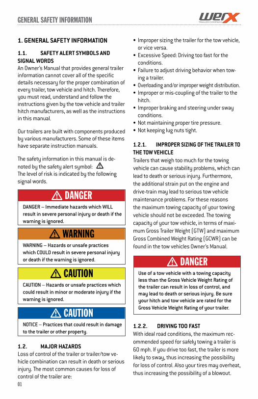
m DanGer
DANGER – Immediate hazards which WILL result in severe personal injury or death if the warning is ignored.
m DanGer
WARNING – Hazards or unsafe practices which COULD result in severe personal injury or death if the warning is ignored.
m WarninG
CAUTION – Hazards or unsafe practices which could result in minor or moderate injury if the warning is ignored.
m cauTion
NOTICE – Practices that could result in damage to the trailer or other property.
m cauTion

General safeTy informaTion
02
1.2.3. FAILURE TO ADJUST DRIVING BE-HAVIOR WHEN TOWING A TRAILERWhen towing a trailer, you will have decreased acceleration, increased stopping distance, and increased turning radius (which means you must make wider turns to keep from hitting curbs, vehicles, and anything else that is on the inside corner). Furthermore the trailer will change the handling characteristics of your towing vehicle, making it more sensitive to steering inputs and more likely to be pushed around in windy conditions or when being passed by large vehicles. In addition, you will need a longer distance to pass, due to slower acceleration and increased length. With these caveats in mind:
Be alert for slippery conditions. You are more likely to be affected by slippery road surfaces when driving a tow vehicle with a trailer, than driving a tow vehicle without a trailer. Anticipate the trailer “swaying.” Swaying can be caused by excessive steering, wind gusts, roadway edges, or by the trailer reaction to the pressure wave created by passing trucks and busses. When encountering trailer sway take your foot off the gas, and steer as little as possible in order to stay on the road. Use small “trim-like” steering adjustments. Do not attempt to steer out of the sway; you’ll only make it worse. Also do not apply the tow vehicle brakes to correct trailer swaying. On the other hand, application of the trailer brakes alone will tend to straighten out the combination, especially when going downhill. Check rearview mirrors frequently to observe the trailer and traffic. Use lower gear when driving down steep or long grades. Use the engine and transmission as a brake. Do not ride the brakes, as they can overheat and
become ineffective. Be aware of your trailer height, especially when approaching bridges, roofed areas and around trees.
1.2.4. TRAILER NOT PROPERLY COUPLED TO THE HITCH It is critical that the trailer be securely coupled to the hitch ball, and that the safety chains and emergency break-away brake cable are cor-rectly attached. Uncoupling may result in death or serious injury to you and to others.
Proper selection and condition of the coupler and hitch are essential to safely towing your trailer. A loss of coupling may result in death or serious injury. Be sure the hitch load rating is equal to or
greater than the load rating of the coupler. Be sure the hitch size matches the coupler
size Observe the hitch for wear, corrosion and
cracks before coupling. Replace worn, cor-roded or cracked hitch components before coupling the trailer to the tow vehicle.
Be sure the hitch components are tight before coupling the trailer to the tow vehicle.
An improperly coupled trailer can result in death or serious injury. Do not move the trailer until: The coupler is secured and locked to hitch; The safety chains are secured to the tow
vehicle; and The trailer jack(s) are fully retracted.
Do not tow the trailer on the road until: Tires and wheels are checked; The trailer brakes are checked; The breakaway switch is connected to the
tow vehicle; The load is secured to the trailer; and The trailer lights are connected and
checked.
Driving too fast for conditions can result in loss of control and cause death or serious injury. Decrease your speed as road, weather and lighting conditions deteriorate.
m WarninG
m WarninG
m WarninG
03
General safeTy informaTion
1.2.5. PROPER USE OF SAFETY CHAINSIf your trailer comes loose from the hitch for any reason, we have provided safety chains so that control of the trailer can still be maintained.
1.2.6. PROPER CONNECTION OF BREAKAWAY BRAKEIf equipped with brakes your trailer will be equipped with a breakaway brake system that can apply the brakes on your trailer if your trailer comes loose from the hitch ball for any reason. You will have a separate set of instruc-tions for the breakaway brake if your trailer is so equipped. The breakaway brake system, including battery, must be in good condition and properly rigged to be effective.
An ineffective or inoperative breakaway brake system can result in a runaway trailer, leading to death or serious injury if the coupler or hitch fails. The breakaway cable must be connected to the tow vehicle, and NOT to any part of the hitch.
1.2.7. MATCHING TRAILER AND HITCH
1.2.8. WORN TIRES, LOOSE WHEELS AND LUG NUTSJust as with your tow vehicle the trailer tires and wheels are important safety items. Therefore, it is essential to inspect the trailer tires before each tow.
If a tire has a bald spot, bulge, cut, cracks, or is showing any cords, replace the tire before towing. If a tire has uneven tread wear, take the trailer to a dealer service center for diagnosis. Un-even tread wear can be caused by tire imbalance, axle misalignment or incorrect inflation.Tires with too little tread will not provide adequate frictional forces on wet roadways and can result in loss of control, leading to death or serious injury.
Improper tire pressure causes increased tire wear and may reduce trailer stability, which can result in a tire blowout or possible loss of control. Therefore, before each tow you must also check the tire pressure. Remember, the proper tire pressure is listed on the Certification / VIN label, normally mounted on front left side of the trailer, and should be checked when tires are cold. Allow 3 hours cool-down after driving as much as 1 mile at 40 mph before checking tire pressure.
The tightness of the lug nuts is very important in keeping the wheels properly seated to the hub. Be-fore each tow, check to make sure they are tight.
m WarninG
Use of a hitch with a load rating less than the load rating of the trailer can result in loss of control and may lead to death or serious injury.
m DanGer
Improper tire pressure can result in a blowout and loss of control, which can lead to death or serious injury. Be sure tires are inflated to pressure indicated on sidewall before towing trailer.
m WarninG
Metal creep between the wheel rim and lug nuts will cause rim to loosen and could result in a wheel coming off, leading to death or serious injury. Tighten lug nuts before each tow.
m WarninG
Improper rigging of the safety chains can result in loss of control of the trailer and tow vehicle, leading to death or serious injury, if the trailer uncouples from the tow vehicle.• Fastenchainstoframeoftowvehicle.Do
not fasten chains to any part of the hitch unless the hitch has holes or loops specifi-cally for that purpose.
• Crosschainsunderneathhitchandcouplerwith enough slack to permit turning and to hold tongue up, if the trailer comes loose.
m WarninG
04
General safeTy informaTion
The proper tightness (torque) for lug nuts is listed in Section 5.2.11.2 in the “Inspec-tion and Service Instructions” chapter of this manual. Use a torque wrench to tighten the lug nuts, use the crisscross star pattern on page 28. If you do not have a torque wrench, use a lug wrench (from your tow vehicle) and tighten the nuts as much as you can. At the first opportunity, have a service garage or trailer dealer tighten the lug nuts to the proper torque.
Lug nuts are also prone to loosen after first being assembled. When driving a new trailer (or after wheels have been remounted), check to make sure they are tight after the first 10, 25 and 50 miles of driving and before each tow thereafter.
Failure to perform this check can result in a wheel separating from the trailer and a crash, leading to death or serious injury.
1.2.9. IMPROPER LOADINGThe total weight of the load you put in or on the trailer, plus the empty weight of the trailer itself, must not exceed the trailer’s Gross Ve-hicle Weight Rating (GVWR). If you do not know the empty weight of the trailer plus the cargo weight, you must weigh the loaded trailer at a commercial scale. In addition, you must distrib-ute the load in the trailer such that the load on any axle does not exceed the Gross Axle Weight Rating (GAWR). If your trailer is equipped with a Tire & Loading Information Placard, mounted next to the Certification / VIN label, the cargo capacity weight stated on that placard is only a close estimate. The GVWR and GAWR’s are
listed on the Certification / VIN label mounted on the front left side of the trailer.
1.2.10. UNSAFE LOAD DISTRIBUTIONImproper front / rear load distribution can lead to poor trailer sway stability or poor tow vehicle handling. Poor trailer sway stability results from tongue weights that are too low, and poor tow vehicle stability results from tongue weights that are too high. Refer to Chapter heading “Improper Loading” for more informa-tion.
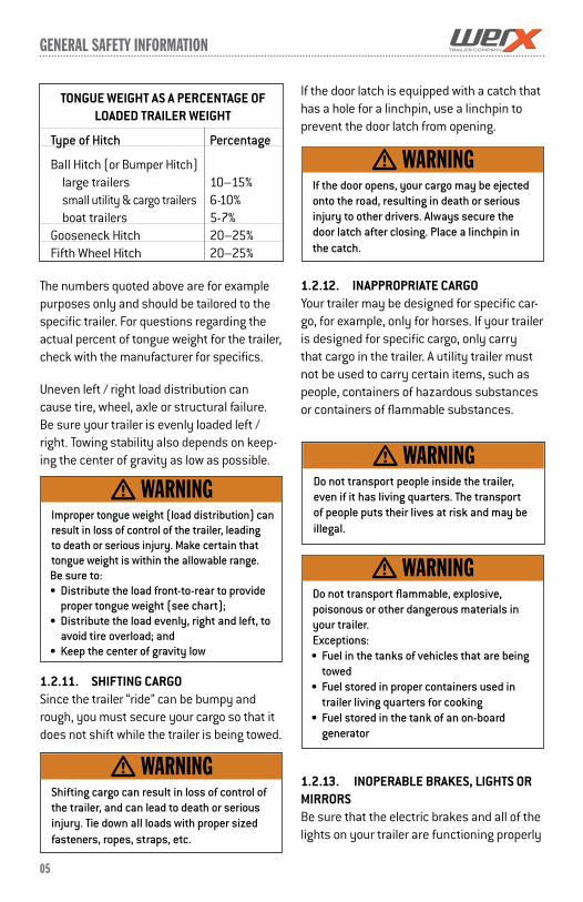
In the table on page 05, the second column shows the rule of thumb percentage of total weight of the trailer plus its cargo (Gross Trailer Weight, or “GTW”) that should appear on the tongue of the trailer. For example, a trailer with a gooseneck hitch, with a loaded weight of 12,000 pounds, should have 20-25% of 12,000 pounds (2400-3000 lbs.) on the gooseneck. A dump trailer will have the proper weight distri-bution if the load is evenly distributed in the dump bed. For non-flowable (discrete) loads locate the load such as to provide the proper tongue weight.
After loading, be sure to check that none of the axles are overloaded.
Lug nuts are prone to loosen after initial installation, which can lead to death or serious injury. Check lug nuts for tightness on a new trailer or when wheel(s) have been remounted after the first 10, 25 and 50 miles of driving.
m WarninG
Improper lug nut torque can cause a wheel separating from the trailer, leading to death or serious injury. Be sure lug nuts are tight before each tow.
m WarninG
An overloaded trailer can result in loss of control of the trailer, leading to death or serious injury. Do not exceed the trailer Gross Vehicle Weight Rating (GVWR) or the Gross Axle Weight Rating (GAWR). Do not load a trailer so that the weight on any tire exceeds its rating.
m WarninG
General safeTy informaTion
05
The numbers quoted above are for example purposes only and should be tailored to the specific trailer. For questions regarding the actual percent of tongue weight for the trailer, check with the manufacturer for specifics.
Uneven left / right load distribution can cause tire, wheel, axle or structural failure. Be sure your trailer is evenly loaded left / right. Towing stability also depends on keep-ing the center of gravity as low as possible.
1.2.11. SHIFTING CARGOSince the trailer “ride” can be bumpy and rough, you must secure your cargo so that it does not shift while the trailer is being towed.
If the door latch is equipped with a catch that has a hole for a linchpin, use a linchpin to prevent the door latch from opening.
1.2.12. INAPPROPRIATE CARGOYour trailer may be designed for specific car-go, for example, only for horses. If your trailer is designed for specific cargo, only carry that cargo in the trailer. A utility trailer must not be used to carry certain items, such as people, containers of hazardous substances or containers of flammable substances.
1.2.13. INOPERABLE BRAKES, LIGHTS OR MIRRORSBe sure that the electric brakes and all of the lights on your trailer are functioning properly
TONGUE WEIGHT AS A PERCENTAGE OF LOADED TRAILER WEIGHT
Type of Hitch Percentage
Ball Hitch (or Bumper Hitch) large trailers 10–15% small utility & cargo trailers 6-10% boat trailers 5-7%Gooseneck Hitch 20–25% Fifth Wheel Hitch 20–25%
Improper tongue weight (load distribution) can result in loss of control of the trailer, leading to death or serious injury. Make certain that tongue weight is within the allowable range.Be sure to:• Distributetheloadfront-to-reartoprovide
proper tongue weight (see chart);• Distributetheloadevenly,rightandleft,to
avoid tire overload; and• Keepthecenterofgravitylow
m WarninG
Shifting cargo can result in loss of control of the trailer, and can lead to death or serious injury. Tie down all loads with proper sized fasteners, ropes, straps, etc.
m WarninG
If the door opens, your cargo may be ejected onto the road, resulting in death or serious injury to other drivers. Always secure the door latch after closing. Place a linchpin in the catch.
m WarninG
Do not transport people inside the trailer, even if it has living quarters. The transport of people puts their lives at risk and may be illegal.
m WarninG
Do not transport flammable, explosive,poisonous or other dangerous materials in your trailer.Exceptions:• Fuelinthetanksofvehiclesthatarebeing
towed• Fuelstoredinpropercontainersusedin
trailer living quarters for cooking• Fuelstoredinthetankofanon-board
generator
m WarninG
General safeTy informaTion
06
1.2.13. INOPERABLE BRAKES, LIGHTS OR MIRRORS (continued)
before towing your trailer. Electric brakes and lights on a trailer are controlled via a connection to the tow vehicle, generally a multi-pin electrical connector. Check the trailer tail lights by turning on your tow vehicle headlights. Check the trailer brake lights by having someone step on the tow vehicle brake pedal while you look at trailer lights. Do the same thing to check the turn signal lights.
If your trailer has electric brakes, your tow vehicle will have an electric brake controller that sends power to the trailer brakes. Before towing the trailer on the road, you must oper-ate the brake controller while trying to pull the trailer in order to confirm that the electric brakes operate. While towing the trailer at less than 5 mph, manually operate the elec-tric brake controller in the tow vehicle cab. You should feel the operation of the trailer brakes.
Improper electrical connection between the tow vehicle and the trailer will result in inoperable lights and electric brakes, and can lead to collision.Before each tow: Check that the taillights, brake lights and
turn signals work Check that the electric brakes work by
operating the brake controller inside the tow vehicle
If your trailer has hydraulic “surge” brakes, pull the emergency break-away brake lanyard to check the operation of the surge mechanism.
Standard mirrors usually do not provide adequate visibility for viewing traffic to the sides and rear a towed trailer. You must pro-vide mirrors that allow you to safely observe approaching traffic.
1.2.14. HAZARDS FROM MODIFYING YOUR TRAILEREssential safety items can be damaged by al-tering your trailer. Even simply driving a nail or screw to hang something can damage an electrical circuit, LP gas line or other feature of the trailer.
Before making any alteration to your trailer, contact your dealer or WerX Trailers at 574.848.7500 and describe the altera-tion you are contemplating. Alteration of the trailer structure or modification of mechani-cal, electrical, plumbing, heating or other sys-tems on your trailer must be performed only by qualified technicians who are familiar with the system as installed on your trailer.
1.2.15. HAZARDS FROM ACCESSORIESRead and follow all of the instructions before operating the accessories. The major hazards from some of these accessories are:
1.2.15.1. GENERATORIf your trailer is equipped with a gasoline or diesel generator, you must have and follow the generator manufacturer’s instructions. You must also have one or more carbon monoxide detectors in the trailer’s accommo-dation spaces.
Carbon Monoxide is an odorless gas that can cause death. Be certain exhaust from a running generator does not accumulate in or around your trailer, by situations such as:
m WarninG
General safeTy informaTion
07
Being drawn in by fans or ventilators operated in a trailer;
Prevailing wind; Being trapped between your trailer and
other trailers, vehicles or buildings; or Being trapped between your trailer and, or
in a snow bank, or other nearby objects
1.2.15.2. SHORE POWER“Shore Power” is the name given to con-necting your trailer to a source of electrical power using an extension cord specifically designed for that purpose.
1.2.15.3. LP GAS FUEL SYSTEM
Risk of death due to fire or explosion. Only connect an LP gas system to a supply
of LP gas, NOT natural gas. Do not store LP gas tanks inside the trailer. Only fill an LP gas tank 80% full. Only fill the tank with LP gas (butane or
propane). Overfilled tanks can release gas and cause
an explosion.
Risk of fire or explosion Never use a flame, heat lamp or hair dryer
to thaw an LP gas regulator. Use an incan-descent light bulb.
Do not remove the regulator cover or attempt to service the LP gas regulator.
Operating gasoline and diesel generators can lead to death or serious injury by:• CarbonMonoxide• FireandExplosion• Electrocution
m WarninG
Shore power poses a risk of death due to electrocution or fire• Alwaysuseanelectricalcordspecifically
designed for shore power connection. Never use an ordinary extension cord.
• Alwaysconnecttheelectricalcordtoagrounded source of shore power.
• Donotremovethe“thirdprong”fromtheshore power plug.
• Connectonlytosourceofpropervoltage.• Makecertainpolarityiscorrect.• Donotoverloadelectricalcircuits.• Alwaysreplacefusesorcircuitbreakers
with correct rating.
m WarninG
You can die or be brain damaged by Carbon Monoxide. Make certain the exhaust from LP appliances is directed to the outdoors. Have a working carbon monoxide detector in the accommodation spaces of your trailer before operating any LP gas appliance.Do not operate portable grills or stoves inside the trailer.
m WarninG
m WarninG
Risk of fire or explosionIf LP gas is detected (by smell or by the LP gas detector):• Donottouchelectricalswitches• Extinguishflamesandpilotlights• Opendoorsforventilation• ShutoffLPgassupplyattheLPtank• Leavetheareauntilodorclears
Correct the source of LP gas leakage before using LP appliances.Do not use a flame to locate the source of an LP gas leak.
m WarninG
m WarninG
General safeTy informaTion
08
1.2.16. SAFETY WARNING LABELS ON YOUR TRAILER
1.2.17. TRAILER TOWING GUIDEDriving a vehicle with a trailer in tow is vastly different from driving the same vehicle without a trailer in tow. Acceleration, maneuverability and braking are all diminished with a trailer in tow. It takes longer to get up to speed; you need more room to turn and pass, and more distance to stop when towing a trailer. You will need to spend time adjusting to the different feel and maneuverability of the tow vehicle with a loaded trailer. Because of the significant differences in all aspects of maneuverability when towing a trailer, the hazards and risks of injury are also much greater than when driving without a trailer. You are responsible for keeping your vehicle and trailer in control, and for all the damage that is caused if you lose control of your vehicle and trailer.
As you did when learning to drive an automo-bile, find an open area with little or no traffic for your first practice trailering. Of course, before you start towing the trailer, you must follow all of the instructions for inspection, testing, loading and coupling. Also, before you start towing, adjust the mirrors so you can see the trailer as well as the area to the rear of it.
Drive slowly at first, 5 mph or so, and turn the wheel to get the feel of how the tow ve-
hicle and trailer combination responds. Next, make some right and left hand turns. Watch in your side mirrors to see how the trailer follows the tow vehicle. Turning with a trailer attached requires more room.
Stop the rig a few times from speeds no greater than 10 mph. If your trailer is equipped with brakes, try using different combinations of trailer/electric brake and tow vehicle brake. Note the effect that the trailer brakes have when they are the only brakes used. When properly adjusted, the trailer brakes will come on just before the tow vehicle brakes.
It will take practice to learn how to back up a tow vehicle with a trailer attached. Take it slow. Before backing up, get out of the tow vehicle and look behind the trailer to make sure that there are no obstacles. Some driv-ers place their hands at the bottom of the steering wheel, and while the tow vehicle is in reverse, “think” of the hands as being on the top of the wheel. When the hands move to the right (counter-clockwise, as you would do to turn the tow vehicle to the left when moving forward), the rear of the trailer moves to the right. Conversely, rotating the steering wheel clockwise with your hands at the bottom of the wheel will move the rear of the trailer to the left, while backing up. If you are towing a bumper hitch rig, be careful not to allow the trailer to turn too much, because it will hit the rear of the tow vehicle. To straighten the rig, either pull forward, or turn the steering wheel in the opposite direction.
1.2.18. REPORTING SAFETY DEFECTSIf you believe that your vehicle has a defect that could cause a crash or could cause in-jury or death, you should immediately inform the National Highway Traffic Safety Adminis-
To protect you and others against death or serious injury, all of the labels shown above must be on the trailer and must be legible.
If any of these labels are missing or cannot be read, call WerX Trailers at 574.848.7550 for free replacement labels.
You will need to provide us with the number shown at the bottom of the label(s) in order for us to send the correct one(s).
m WarninG

General safeTy informaTion
09
1.2.18. REPORTING SAFETY DEFECTS (cont.)
tration (NHTSA) in addition to notifying WerX Trailers.
If NHTSA receives similar complaints, it may open an investigation, and if it finds that a safety defect exists in a group of vehicles, it may order a recall and remedy campaign. However, NHTSA cannot become involved in individual problems between you, your dealer, or WerX Trailers.
To contact NHTSA, you may either call the Vehicle Safety Hotline toll-free at 1-888-327-4236 (TTY: 1-800-424-9153), go to http://www.safecar.gov; or write to: Administrator, NHTSA, 1200 New Jersey Ave. SE., Wash-ington, DC 20590. You can also obtain other information about motor vehicle safety from http://www.safecar.gov.
Call 574.848.7500 to reach WerX Trailers.
1.3. SAFE TRAILER TOWING GUIDELINES Recheck the load tiedowns to make sure
the load will not shift during towing. Before towing, check coupling, safety
chain, safety brake, tires, wheels and lights.
Check the lug nuts or bolts for tightness. Check coupler tightness after towing 50
miles. Adjust the brake controller to engage
the trailer brakes before the tow vehicle brakes. Follow the instructions given with the brake controller manufacturer’s literature.
Use your mirrors to verify that you have room to change lanes or pull into traffic.
Use your turn signals well in advance. Allow plenty of stopping space for your
trailer and tow vehicle.
Do not drive so fast that the trailer begins to sway due to speed. Generally never drive faster than 60 m.p.h.
Allow plenty of room for passing. A rule of thumb is that the passing distance with a trailer is 4 times the passing distance without a trailer.
Shift your automatic transmission into a lower gear for city driving.
Use lower gears for climbing and descend-ing grades.
Do not ride the brakes while descending grades, they may get so hot that they stop working. Then you will potentially have a runaway tow vehicle and trailer.
To conserve fuel, don’t use full throttle to climb a hill. Instead, build speed on the approach.
Slow down for bumps in the road. Take your foot off the brake when crossing the bump.
Do not brake while in a curve unless absolutely necessary. Instead, slow down before you enter the curve.
Do not apply the tow vehicle brakes to correct extreme trailer swaying. Instead, lightly apply the trailer brakes with the hand controller.
Make regular stops, about once each hour. Confirm that
The coupler is secure to the hitch and is locked
Electrical connectors are made, There is appropriate slack in the safety
chains, There is appropriate slack in the breakaway
switch pullpin cable, The tires are not visibly low on pressure The cargo is secure and in good condition.
10
Tire safeTy informaTion
This portion of the User’s Manual contains tire safety information as required by 49 CFR 575.6.
Section 2.1 contains “Steps for Determining Correct Load Limit - Trailer”.
Section 2.2 contains “Steps for Determining Correct Load Limit – Tow Vehicle”.
Section 2.3 contains a Glossary of Tire Terminology, including “cold inflation pressure”, “maximum inflation pressure”, “recommended inflation pressure”, and other non-technical terms.
Section 2.4 contains information from the NHTSA brochure entitled “Tire Safety – Every-thing Rides On It”. This brochure describes the following items; Tire labeling, including a description and
explanation of each marking on the tires, and information about the DOT Tire Identifi-cation Number (TIN).
Recommended tire inflation pressure, including a description and explanation of:
A. Cold inflation pressure. B. Vehicle Placard and location on the vehicle. C. Adverse safety consequences of under inflation (including tire failure). D. Measuring and adjusting air pressure for proper inflation. Tire Care, including maintenance and
safety practices. Vehicle load limits, including a description
and explanation of the following items: A. Locating and understanding the load limit information, total load capacity, and cargo capacity. B. Calculating total and cargo capacities with varying seating configurations
B. including quantitative examples showing/ illustrating how the vehicles cargo and luggage capacity decreases as combined number and size of occupants’ increases. This item is also discussed in Section 3. C. Determining compatibility of tire and vehicle load capabilities. D. Adverse safety consequences of overloading on handling and stopping on tires.
2.1. STEPS FOR DETERMINING CORRECT LOAD LIMIT – TRAILER
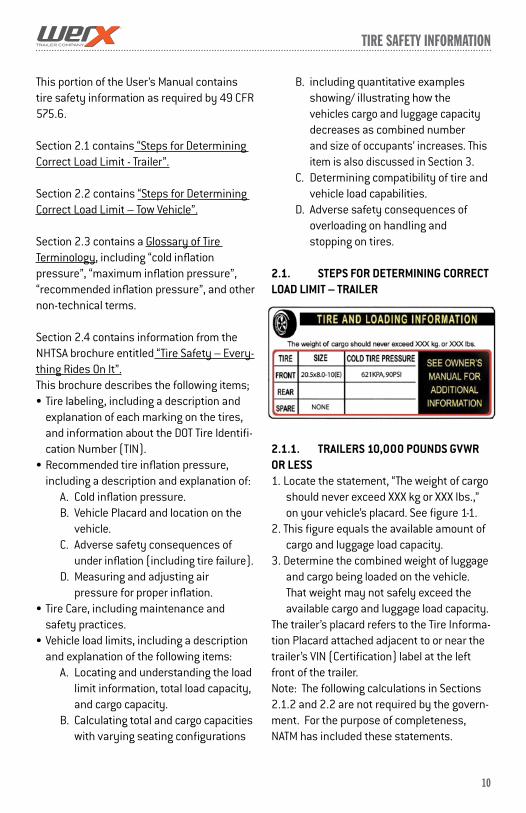
2.1.1. TRAILERS 10,000 POUNDS GVWR OR LESS1. Locate the statement, “The weight of cargo
should never exceed XXX kg or XXX lbs.,” on your vehicle’s placard. See figure 1-1.
2. This figure equals the available amount of cargo and luggage load capacity.
3. Determine the combined weight of luggage and cargo being loaded on the vehicle. That weight may not safely exceed the available cargo and luggage load capacity.
The trailer’s placard refers to the Tire Informa-tion Placard attached adjacent to or near the trailer’s VIN (Certification) label at the left front of the trailer. Note: The following calculations in Sections 2.1.2 and 2.2 are not required by the govern-ment. For the purpose of completeness, NATM has included these statements.

11
Tire safeTy informaTion
2.1.2. TRAILERS OVER 10,000 POUNDS GVWR (NOTE: THESE TRAILERS ARE NOT REQUIRED TO HAVE A TIRE INFORMATION PLACARD ON THE VEHICLE)1. Determine the empty weight of your trailer
by weighing the trailer using a public scale or other means. This step does not have to be repeated.
2. Locate the GVWR (Gross Vehicle Weight Rating) of the trailer on your trailer’s VIN (Certification) label.
3. Subtract the empty weight of your trailer from the GVWR stated on the VIN label. That weight is the maximum available cargo capacity of the trailer and may not be safely exceeded.
2.2. STEPS FOR DETERMINING CORRECT LOAD LIMIT – MOW VEHICLE1. Locate the statement, “The combined
weight of occupants and cargo should never exceed XXX lbs.,” on your vehicle’s placard.
2. Determine the combined weight of the driver and passengers who will be riding in your vehicle.
3. Subtract the combined weight of the driver and passengers from XXX kilograms or XXX pounds.
4. The resulting figure equals the available amount of cargo and luggage capacity. For example, if the “XXX” amount equals 1400 lbs. and there will be five 150 lb. passengers in your vehicle, the amount of available cargo and luggage capacity is 650 lbs. (1400-750 (5 x 150) = 650 lbs.).
5. Determine the combined weight of luggage and cargo being loaded on the vehicle. That weight may not safely exceed the avail-able cargo and luggage capacity calculated in Step # 4.
6. If your vehicle will be towing a trailer, load from your trailer will be transferred to your
vehicle. Consult the tow vehicle’s manual to determine how this weight transfer reduces the available cargo and luggage capacity of your vehicle.
2.3. GLOSSARY OF TIRE TERMINOLOGYACCESSORY WEIGHTThe combined weight (in excess of those standard items which may be replaced) of automatic transmission, power steering, power brakes, power windows, power seats, radio and heater, to the extent that these items are available as factory-installed equipment (whether installed or not).
BeadThe part of the tire that is made of steel wires, wrapped or reinforced by ply cords and that is shaped to fit the rim.
Bead separationThis is the breakdown of the bond between components in the bead.
Bias ply tireA pneumatic tire in which the ply cords that extend to the beads are laid at alternate angles substantially less than 90 degrees to the centerline of the tread.
CarcassThe tire structure, except tread and sidewall rubber which, when inflated, bears the load.
ChunkingThe breaking away of pieces of the tread or sidewall.
Cold inflation pressureThe pressure in the tire before you drive.
CordThe strands forming the plies in the tire.
12
Tire safeTy informaTion
Cord separationThe parting of cords from adjacent rubber compounds.
CrackingAny parting within the tread, sidewall, or inner liner of the tire extending to cord material.
CTA pneumatic tire with an inverted flange tire and rim system in which the rim is designed with rim flanges pointed radially inward and the tire is designed to fit on the underside of the rim in a manner that encloses the rim flanges inside the air cavity of the tire.
Curb weightThe weight of a motor vehicle with standard equipment including the maximum capacity of fuel, oil, and coolant, and, if so equipped, air conditioning and additional weight op-tional engine.
Extra load tireA tire designed to operate at higher loads and at higher inflation pressures than the corresponding standard tire.
GrooveThe space between two adjacent tread ribs.
InnerlinerThe layer(s) forming the inside surface of a tubeless tire that contains the inflating medium within the tire.
Innerliner separationThe parting of the innerliner from cord mate-rial in the carcass.
Intended outboard sidewallThe sidewall that contains a white-wall, bears white lettering or bears manufacturer, brand, and/or model name molding that is higher or deeper than the same molding on
the other sidewall of the tire or the outward facing sidewall of an asymmetrical tire that has a particular side that must always face outward when mounted on a vehicle.
Light truck (LT) tireA tire designated by its manufacturer as pri-marily intended for use on lightweight trucks or multipurpose passenger vehicles.
Load ratingThe maximum load that a tire is rated to carry for a given inflation pressure.
Maximum load ratingThe load rating for a tire at the maximum permissible inflation pressure for that tire.
Maximum permissible inflation pressureThe maximum cold inflation pressure to which a tire may be inflated.
Maximum loaded vehicle weightThe sum of curb weight, accessory weight, vehicle capacity weight, and production op-tions weight.
Measuring rimThe rim on which a tire is fitted for physical dimension requirements.
Non-pneumatic rimA mechanical device which, when a non-pneumatic tire assembly incorporates a wheel, supports the tire, and attaches, either integrally or separably, to the wheel center member and upon which the tire is attached.
Non-pneumatic spare tire assemblyA non-pneumatic tire assembly intended for temporary use in place of one of the pneumatic tires and rims that are fitted to a passenger car in compliance with the requirements of this standard.
13
Tire safeTy informaTion
Non-pneumatic tireA mechanical device which transmits, either directly or through a wheel or wheel center member, the vertical load and tractive forces from the roadway to the vehicle, generates the tractive forces that provide the direc-tional control of the vehicle and does not rely on the containment of any gas or fluid for providing those functions.
Non-pneumatic tire assemblyA non-pneumatic tire, alone or in combina-tion with a wheel or wheel center member, which can be mounted on a vehicle.
Normal occupant weightThis means 68 kilograms (150 lbs.) times the number of occupants specified in the second column of Table I of 49 CFR 571.110.
Occupant distribution The distribution of occupants in a vehicle as specified in the third column of Table I of 49 CFR 571.110.
Open spliceAny parting at any junction of tread, sidewall, or innerliner that extends to cord material.
Outer diameterThe overall diameter of an inflated new tire.
Overall widthThe linear distance between the exteriors of the sidewalls of an inflated tire, including elevations due to labeling, decorations, or protective bands or ribs.
PlyA layer of rubber-coated parallel cords.
Ply separationA parting of rubber compound between adjacent plies.
Pneumatic tireA mechanical device made of rubber, chemi-cals, fabric and steel or other materials, that, when mounted on an automotive wheel, provides the traction and contains the gas or fluid that sustains the load.
Production options weightThe combined weight of those installed regular production options weighing over 2.3 kilograms (5 lbs.) in excess of those standard items which they replace, not previ-ously considered in curb weight or accessory weight, including heavy duty brakes, ride levelers, roof rack, heavy duty battery, and special trim.
Radial ply tireA pneumatic tire in which the ply cords that extend to the beads are laid at substantially 90 degrees to the centerline of the tread.
Recommended inflation pressureThis is the inflation pressure provided by the vehicle manufacturer on the Tire Information label and on the Certification / VIN tag.
Reinforced tireA tire designed to operate at higher loads and at higher inflation pressures than the corresponding standard tire.
RimA metal support for a tire or a tire and tube assembly upon which the tire beads are seated.
Rim diameterThis means the nominal diameter of the bead seat.
Rim size designationThis means the rim diameter and width.
14
Tire safeTy informaTion
Rim type designationThis means the industry of manufacturer’s designation for a rim by style or code.
Rim widthThis means the nominal distance between rim flanges.
Section widthThe linear distance between the exteriors of the sidewalls of an inflated tire, excluding elevations due to labeling, decoration, or protective bands.
SidewallThat portion of a tire between the tread and bead.
Sidewall separationThe parting of the rubber compound from the cord material in the sidewall.
Special Trailer (ST) tireThe “ST” is an indication the tire is for trailer use only.
Test rimThe rim on which a tire is fitted for testing, and may be any rim listed as appropriate for use with that tire.
TreadThat portion of a tire that comes into contact with the road.
Tread ribA tread section running circumferentially around a tire.
Tread separationPulling away of the tread from the tire carcass.
Treadwear indicators (TWI)The projections within the principal grooves
designed to give a visual indication of the degrees of wear of the tread.
Vehicle capacity weightThe rated cargo and luggage load plus 68 kilograms (150 lbs.) times the vehicle’s designated seating capacity.
Vehicle maximum load on the tireThe load on an individual tire that is deter-mined by distributing to each axle its share of the maximum loaded vehicle weight and dividing by two.
Vehicle normal load on the tireThe load on an individual tire that is deter-mined by distributing to each axle its share of the curb weight, accessory weight, and normal occupant weight (distributed in ac-cordance with Table I of CRF 49 571.110) and dividing by 2.
Weather sideThe surface area of the rim not covered by the inflated tire.
Wheel center memberIn the case of a non-pneumatic tire assembly incorporating a wheel, a mechanical device which attaches, either integrally or separa-bly, to the non-pneumatic rim and provides the connection between the non-pneumatic rim and the vehicle; or, in the case of a non-pneumatic tire assembly not incorporating a wheel, a mechanical device which attaches, either integrally or separably, to the non-pneumatic tire and provides the connection between tire and the vehicle.
Wheel-holding fixtureThe fixture used to hold the wheel and tire assembly securely during testing.
15
Tire safeTy informaTion
2.4. TIRE SAFETY - EVERYTHING RIDES ON ITThe National Traffic Safety Administration (NHTSA) has published a brochure (DOT HS 809 361) that discusses all aspects of Tire Safety, as required by CFR 575.6. This bro-chure is reproduced in part below. It can be obtained and downloaded from NHTSA, free of charge, from the following web site:
http://www.nhtsa.dot.gov/cars/rules/Tire-Safety/ridesonit/tires_index.html
Studies of tire safety show that maintain-ing proper tire pressure, observing tire and vehicle load limits (not carrying more weight in your vehicle than your tires or vehicle can safely handle), avoiding road hazards, and inspecting tires for cuts, slashes, and other irregularities are the most important things you can do to avoid tire failure, such as tread separation or blowout and flat tires. These actions, along with other care and mainte-nance activities, can also:
Improve vehicle handling Help protect you and others from avoidable
breakdowns and accidents Improve fuel economy Increase the life of your tires.
This booklet presents a comprehensive overview of tire safety, including information on the following topics: Basic tire maintenance Uniform Tire Quality Grading System Fundamental characteristics of tires Tire safety tips.
Use this information to make tire safety a regular part of your vehicle maintenance routine. Recognize that the time you spend is minimal compared with the inconvenience
and safety consequences of a flat tire or other tire failure.
2.4.1. SAFETY FIRST–BASIC TIRE MAINTENANCEProperly maintained tires improve the steer-ing, stopping, traction, and load-carrying capability of your vehicle. Underinflated tires and overloaded vehicles are a major cause of tire failure. Therefore, as mentioned above, to avoid flat tires and other types of tire failure, you should maintain proper tire pressure, ob-serve tire and vehicle load limits, avoid road hazards, and regularly inspect your tires.
2.4.2. FINDING YOUR VEHICLE’S RECOMMENDED TIRE PRESSURE AND LOAD LIMITSTire information placards and vehicle certifi-cation labels contain information on tires and load limits. These labels indicate the vehicle manufacturer’s information including:
Recommended tire size Recommended tire inflation pressure Vehicle capacity weight (VCW–the maxi-
mum occupant and cargo weight a vehicle is designed to carry)
Front and rear gross axle weight ratings (GAWR– the maximum weight the axle systems are designed to carry).
Both placards and certification labels are permanently attached to the trailer near the left front.
2.4.3. UNDERSTANDING TIRE PRESSURE AND LOAD LIMITSTire inflation pressure is the level of air in the tire that provides it with load-carrying capac-ity and affects the overall performance of the vehicle. The tire inflation pressure is a num-ber that indicates the amount of air pres-
16
Tire safeTy informaTion
sure– measured in pounds per square inch (psi)–a tire requires to be properly inflated. (You will also find this number on the vehicle information placard expressed in kilopascals (kPa), which is the metric measure used internationally.)
Manufacturers of passenger vehicles and light trucks determine this number based on the vehicle’s design load limit, that is, the greatest amount of weight a vehicle can safely carry and the vehicle’s tire size. The proper tire pressure for your vehicle is referred to as the “recommended cold inflation pressure.” (As you will read below, it is difficult to obtain the recommended tire pressure if your tires are not cold.)Because tires are designed to be used on more than one type of vehicle, tire manu-facturers list the “maximum permissible inflation pressure” on the tire sidewall. This number is the greatest amount of air pres-sure that should ever be put in the tire under normal driving conditions.
2.4.4. CHECKING TIRE PRESSUREIt is important to check your vehicle’s tire pressure at least once a month for the fol-lowing reasons:
Most tires may naturally lose air over time. Tires can lose air suddenly if you drive over
a pothole or other object or if you strike the curb when parking.
With radial tires, it is usually not possible to determine underinflation by visual inspection.
For convenience, purchase a tire pressure gauge to keep in your vehicle. Gauges can be purchased at tire dealerships, auto supply stores, and other retail outlets.
The recommended tire inflation pressure that vehicle manufacturers provide reflects the prop-er psi when a tire is cold. The term cold does not relate to the outside temperature. Rather, a cold tire is one that has not been driven on for at least three hours. When you drive, your tires get warmer, causing the air pressure within them to increase. Therefore, to get an accurate tire pres-sure reading, you must measure tire pressure when the tires are cold or compensate for the extra pressure in warm tires.
2.4.5. STEPS FOR MAINTAINING PROPER TIRE PRESSURE Step 1: Locate the recommended tire
pressure on the vehicle’s tire information placard, certification label, or in the owner’s manual.
Step 2: Record the tire pressure of all tires. Step 3: If the tire pressure is too high in
any of the tires, slowly release air by gen-tly pressing on the tire valve stem with the edge of your tire gauge until you get to the correct pressure.
Step 4: If the tire pressure is too low, note the difference between the measured tire pressure and the correct tire pressure. These “missing” pounds of pressure are what you will need to add.
Step 5: At a service station, add the miss-ing pounds of air pressure to each tire that is underinflated.
Step 6: Check all the tires to make sure they have the same air pressure (except in cases in which the front and rear tires are supposed to have different amounts of pressure).
If you have been driving your vehicle and think that a tire is underinflated, fill it to the recommended cold inflation pressure indicated on your vehicle’s tire information placard or certification label. While your tire may still be slightly underinflated due to

17
Tire safeTy informaTion
the extra pounds of pressure in the warm tire, it is safer to drive with air pressure that is slightly lower than the vehicle manufac-turer’s recommended cold inflation pressure than to drive with a significantly underin-flated tire. Since this is a temporary fix, don’t forget to recheck and adjust the tire’s pres-sure when you can obtain a cold reading.
2.4.6. TIRE SIZETo maintain tire safety, purchase new tires that are the same size as the vehicle’s original tires or another size recommended by the manufacturer. Look at the tire information placard, the owner’s manual, or the sidewall of the tire you are replacing to find this informa-tion. If you have any doubt about the correct size to choose, consult with the tire dealer.
2.4.7. TIRE TREAD The tire tread provides the gripping action and traction that prevent your vehicle from slipping or sliding, especially when the road is wet or icy. In general, tires are not safe and should be replaced when the tread is worn down to 1/16 of an inch. Tires have built-in treadwear indicators that let you know when it is time to replace your tires. These indica-tors are raised sections spaced intermittent-ly in the bottom of the tread grooves. When they appear “even” with the outside of the tread, it is time to replace your tires. Another method for checking tread depth is to place a penny in the tread with Lincoln’s head upside down and facing you. If you can see the top of Lincoln’s head, you are ready for new tires.
2.4.8. TIRE BALANCE AND WHEEL ALIGNMENTTo avoid vibration or shaking of the vehicle when a tire rotates, the tire must be properly balanced. This balance is achieved by position-ing weights on the wheel to counterbalance
heavy spots on the wheel-and-tire assembly. A wheel alignment adjusts the angles of the wheels so that they are positioned correctly relative to the vehicle’s frame. This adjustment maximizes the life of your tires. These adjust-ments require special equipment and should be performed by a qualified technician.
2.4.9. TIRE REPAIRThe proper repair of a punctured tire requires a plug for the hole and a patch for the area inside the tire that surrounds the puncture hole. Punctures through the tread can be re-paired if they are not too large, but punctures to the sidewall should not be repaired. Tires must be removed from the rim to be properly inspected before being plugged and patched.
2.4.10. TIRE FUNDAMENTALSFederal law requires tire manufacturers to place standardized information on the side-wall of all tires. This information identifies and describes the fundamental characteristics of the tire and also provides a tire identification number for safety standard certification and in case of a recall.
2.4.10.1. INFORMATION ON PASSENGER VEHICLE TIRESPlease refer to the diagram below.
18
Tire safeTy informaTion
PThe “P” indicates the tire is for passenger vehicles.
Next numberThis three-digit number gives the width in millimeters of the tire from sidewall edge to sidewall edge. In general, the larger the number, the wider the tire.
Next numberThis two-digit number, known as the aspect ratio, gives the tire’s ratio of height to width. Numbers of 70 or lower indicate a short sidewall for improved steering response and better overall handling on dry pavement.
RThe “R” stands for radial. Radial ply construc-tion of tires has been the industry standard for the past 20 years.
Next numberThis two-digit number is the wheel or rim diameter in inches. If you change your wheel size, you will have to purchase new tires to match the new wheel diameter.
Next numberThis two- or three-digit number is the tire’s load index. It is a measurement of how much weight each tire can support. You may find this information in your owner’s manual. If not, contact a local tire dealer. Note: You may not find this information on all tires because it is not required by law.
M+SThe “M+S” or “M/S” indicates that the tire has some mud and snow capability. Most radial tires have these markings; hence, they have some mud and snow capability.
U.S. DOT Tire Identification NumberThis begins with the letters “DOT” and indi-cates that the tire meets all federal stan-dards. The next two numbers or letters are the plant code where it was manufactured, and the last four numbers represent the week and year the tire was built. For exam-ple, the numbers 3197 means the 31st week of 1997. The other numbers are marketing codes used at the manufacturer’s discretion. This information is used to contact consum-ers if a tire defect requires a recall.
Tire Ply Composition and Materials UsedThe number of plies indicates the number of layers of rubber-coated fabric in the tire. In general, the greater the number of plies, the more weight a tire can support. Tire manu-facturers also must indicate the materials in the tire, which include steel, nylon, polyester, and others.
Maximum Load RatingThis number indicates the maximum load in kilograms and pounds that can be carried by the tire.
Maximum Permissible Inflation PressureThis number is the greatest amount of air pressure that should ever be put in the tire under normal driving conditions.
2.4.10.2. UTQGS INFORMATION
Treadwear NumberThis number indicates the tire’s wear rate. The higher the treadwear number is, the lon-ger it should take for the tread to wear down. For example, a tire graded 400 should last twice as long as a tire graded 200.
19
Tire safeTy informaTion
Traction LetterThis letter indicates a tire’s ability to stop on wet pavement. A higher graded tire should allow you to stop your car on wet roads in a shorter distance than a tire with a lower grade. Traction is graded from highest to low-est as “AA”,”A”, “B”, and “C”.
Temperature LetterThis letter indicates a tire’s resistance to heat. The temperature grade is for a tire that is inflated properly and not overloaded. Excessive speed, underinflation or excessive loading, either separately or in combination, can cause heat build-up and possible tire failure. From highest to lowest, a tire’s resis-tance to heat is graded as “A”, “B”, or “C”.
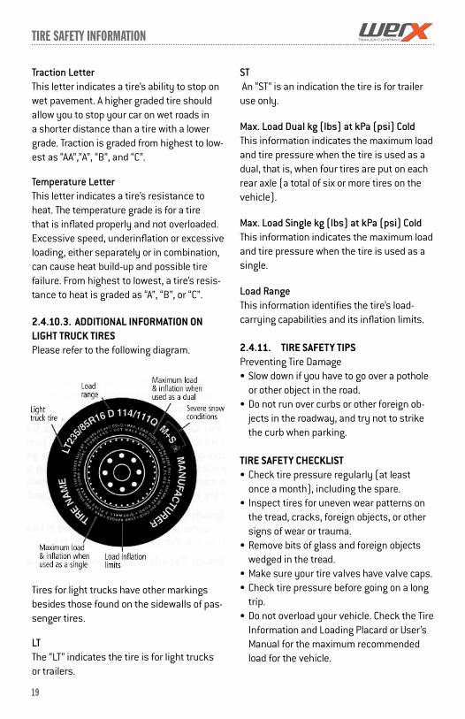
2.4.10.3. ADDITIONAL INFORMATION ON LIGHT TRUCK TIRES Please refer to the following diagram.
Tires for light trucks have other markings besides those found on the sidewalls of pas-senger tires.
LTThe “LT” indicates the tire is for light trucks or trailers.
ST An “ST” is an indication the tire is for trailer use only.
Max. Load Dual kg (lbs) at kPa (psi) ColdThis information indicates the maximum load and tire pressure when the tire is used as a dual, that is, when four tires are put on each rear axle (a total of six or more tires on the vehicle).
Max. Load Single kg (lbs) at kPa (psi) ColdThis information indicates the maximum load and tire pressure when the tire is used as a single.
Load RangeThis information identifies the tire’s load-carrying capabilities and its inflation limits.
2.4.11. TIRE SAFETY TIPSPreventing Tire Damage Slow down if you have to go over a pothole
or other object in the road. Do not run over curbs or other foreign ob-
jects in the roadway, and try not to strike the curb when parking.
TIRE SAFETY CHECKLIST Check tire pressure regularly (at least
once a month), including the spare. Inspect tires for uneven wear patterns on
the tread, cracks, foreign objects, or other signs of wear or trauma.
Remove bits of glass and foreign objects wedged in the tread.
Make sure your tire valves have valve caps. Check tire pressure before going on a long
trip. Do not overload your vehicle. Check the Tire
Information and Loading Placard or User’s Manual for the maximum recommended load for the vehicle.

20
ToWinG cHecKlisT / breaKinG-in a neW Trailer
3. CHECKING THE TRAILER BEFORE AND DURING EACH TOW
3.1. PRE-TOW CHECKLISTBefore towing, double-check all of theseitems: See section 5.1, “Inspection, Service& Maintenance Summary Charts,” for more information.
Tires, wheels and lug nuts (see the “Major Hazards” section starting on page 1 of this manual)
Tire Pressure. Inflate tire on trailer and tow vehicle to the pressure stated on the VIN / Certification label.
Coupler secured and locked Safety chains properly rigged to tow
vehicle, not to hitch or Test of lights: Tail, Stop, and Turn Lights Test trailer brakes. Safety breakaway switch cable fastened to
tow vehicle, not to safety chains Cargo properly loaded, balanced and tied
down Tongue weight and weight distribution set-
up. Doors and gates latched and secured Fire extinguisher Flares and reflectors
3.2. MAKE REGULAR STOPSAfter each 50 miles, or one hour of towing, stop and check the following items:
Coupler secured Safety chains are fastened and not
dragging Cargo secured Cargo door latched and secured
4. BREAKING-IN A NEW TRAILER
4.1. RETIGHTEN LUG NUTS AT FIRST 10, 25 & 50 MILESWheel lugs can shift and settle quickly after being first assembled, and must be checked after the first 10, 25 and 50 miles of driving. Failure to perform this check may result in a wheel coming loose from the trailer, causing a crash leading to death or serious injury.
See Section 5.2.11.2 page 28 on Proper Torquing Technique.
4.2. ADJUST BRAKE SHOES AT FIRST 200 MILESBrake shoes and drums experience a rapid initial wear. The brakes must be adjusted af-ter the first 200 miles of use, and each 3,000 miles thereafter. Some axles are fitted with a mechanism that will automatically adjust the brake shoes when the trailer is “hard braked” from a rearward direction. Read your axle and brake manual to see if your brakes adjust automatically.
A hard stop is used to: Confirm that the brakes work; Confirm that the trailer brakes are properly
synchronized with the tow vehicle brakes using the brake controller in the tow vehicle
Adjust the brake shoes as necessary. For surge brakes check the Master cylinder
reservoir for fluid.
Lug nuts are prone to loosen after initial installation, which can lead to death or serious injury.
Check lug nuts for tightness on a new trailer or when wheel(s) have been remounted after the first 10, 25 and 50 miles of driving.
m WarninG

breaKinG-in a neW Trailer / inspecTion, service & mainTenance
21
If your trailer is not fitted with automatically adjusting brakes, the brakes will need to be manually adjusted. See section 5.2.4.2, “Manually Adjusting Brake Shoes,” for instructions.
4.3. SYNCHRONIZING THE BRAKE SYSTEMSTrailer brakes are designed to work in synchronization with the brakes on the tow vehicle. When the tow vehicle and trailer braking systems are synchronized, both braking systems contribute to slowing, and the tongue of the trailer will neither dive nor rise sharply.
To insure safe brake performance and syn-chronization, read and follow the axle/brake and the brake controller manufacturers’ instructions.
Tire PressureCheck tire pressures on both the trailer and tow vehicle. Inflate to the maximum shown on the VIN / Certification Label.
5. INSPECTION, SERVICE & MAINTENANCE
5.1. INSPECTION, SERVICE & MAINTENANCE SUMMARY CHARTSYou must inspect, maintain and service your trailer regularly to insure safe and reliable operation. If you cannot or are unsure how to perform the items listed here, have your
dealer do them. Note: In addition to this manual, also check the relevant component manufacturer’s manual.
5.2. INSPECTION AND SERVICE INSTRUCTIONS
5.2.1. AXLE BOLTS, FRAME, SUSPENSION,
& STRUCTURE
To perform many of the inspection and maintenance activities, you must jack up the trailer. “Jacking Points for All Trailers” figure indicates the general areas where jacks and jack stands may be applied.
When jacking and using jack stands, place them so as to clear wiring, brake lines, and
suspension parts (springs, torsion bars, etc.). Place jacks and jack stands inside of the perimeter strip on the supporting struc-ture to which the axles are attached.
5.2.2. TRAILER STRUCTUREBecause the trailer floor receives the most
If trailer and tow vehicle brakes do not work properly together, death or serious injury can occur.
Road test the brakes in a safe area at no more than 30 m.p.h. before each tow.
m WarninG
Worn or broken suspension parts can cause loss of control and injury may result. Have trailer professionally inspected annually and after any impact.
m WarninG
Never crawl under your trailer unless it is on firm and level ground and resting on properly placed and secured jack stands.
m WarninG
inspecTion, service & mainTenance
22
abuse, it will most likely corrode before any other part of the structure. This is particu-larly true for horse and livestock trailers, having floors subjected to urine and manure. The urine and manure are corrosive to the metal flooring and other structural parts of the trailer.Remove the rubber mats from the floor of the trailer, and wash them, at least every three months. Using a power washer and a detergent solution, wash both sides of the rubber mat, as well as the floor and walls of the trailer. Rinse the rubber mat and the trailer floor and walls. Be sure the rubber mat and trailer floor are completely dry before replacing the rubber mat.
5.2.2.1. FASTENERS AND FRAME MEMBERSInspect all of the fasteners and structural frame members for bending and other dam-age, cracks, or failure. Repair or replace any damaged fastener and repair the frame member. If you have any questions about the condition or method of repair of fasteners or frame members, get the recommendation of, or have the repair done by, your dealer.
The various fastener types used on your
trailer are:
Bolts, which are used mainly for attaching door and gate hinges to the trailer body;
Screws, which are used mainly for attach-ing skin & trim parts to the trailer body.
Broken or damaged fasteners or welds can cause injury or damage to trailer and contents.
Inspect for, and repair all damaged parts at least once a year.
5.2.2.2. WELDSAll welds can crack or fail when subjected to heavy loads or movement of cargo that was not properly tied to prevent movement.
Any time that you know or suspect that the trailer has been subjected to heavy loads or movement of cargo, immediately inspect the welds and fasteners for damage. To prevent severe damage to your trailer, inspect all of the welds for cracks or failure at least once a year.
5.2.3. DROP RAMP TORSION SPRINGSIf your trailer has a drop-ramp door, the weight of the door may be partially held by a torsion spring and a cable. Stand to the side when opening the drop ramp. You could be hurt if you are behind the drop ramp and the counterbalance does not work.
Inspect the cable and cable ends regularly for fraying and signs of loosening. If released, a torsion spring can inflict serious injury.
The torsion spring and cable are not user ser-viceable. The torsion spring must be serviced by a person who is trained in torsion spring safety.
5.2.4. TRAILER BRAKES
m WarninG
Improper weld repair will lead to early failure of the trailer structure and can cause serious injury or death.
Do not repair cracked or broken welds unless you have the skills and equipment to make a proper repair. If not, have the welds repaired by your dealer.
m WarninG
inspecTion, service & mainTenance
23
5.2.4.1. BRAKE SHOES AND DRUMSProperly functioning brake shoes and drums are essential to ensure safety. You must have your dealer inspect these components at least once per year, or each 12,000 miles.
The brake shoes must be adjusted after the first 200 miles of use, and each 3,000 miles thereafter. Most axles are fitted with a brake mechanism that will automatically adjust the brake shoes when the trailer is “hard braked” from a rearward direction. Read your axle and brake manual to see how to adjust your brakes.
5.2.4.2. MANUALLY ADJUSTING BRAKE SHOESMost braking systems are not automatically adjusted by hard stopping. These brakes require manual adjustment. The follow-ing steps apply to adjust most manually adjustable brakes. Read your axle and brake manual to see how to adjust your brakes.
Jack up the trailer and secure it on ad-equate capacity jack stands.
Be sure the wheel and brake drum rotate freely.
Remove the adjusting-hole cover from the adjusting slot on the bottom of the brake backing plate.
With a screwdriver or standard adjusting tool, rotate the starwheel of the adjuster assembly to expand the brake shoes. Adjust the brake shoes out until the pres-sure of the linings against the drum makes the wheel very difficult to turn. Note: Your trailer maybe equipped with drop spindle axles. See axle manual for your axle type. You will need a modified adjusting tool for adjusting the brakes in these axles. With drop spindle axles, a modified adjusting
tool with about an 80 degree angle should be used.
Rotate the starwheel in the opposite direction until the wheel turns freely with a slight drag.
Replace the adjusting-hole cover. Repeat the above procedure on all brakes. Lower the trailer to the ground.
5.2.4.3. BRAKES, ELECTRICTwo different types of electric brakes may be present on the trailer: an emergency electric breakaway system, which acts only if the trailer comes loose from the hitch and the breakaway pin is pulled. The other brake is an
electric braking system that acts whenever the brakes of the tow vehicle are applied.
5.2.4.3.A. BREAKAWAY BRAKE
5.2.4.3.A.(I) BREAKAWAY BATTERYThis battery supplies the power to operate the trailer brakes if the trailer uncouples from the tow vehicle. Be sure to check, maintain and replace the battery according to the bat-tery manufacturer’ instructions.
5.2.4.3.A.(II) BREAKAWAY SWITCHThis switch causes the breakaway battery
Extreme cold weather can degrade battery performance and cause brakes to not operate properly. Always check battery charge level before towing.
m cauTion
If electric breakaway brakes do not operate when trailer is uncoupled from the tow ve-hicle, death or serious injury can occur.Check emergency breakaway brake system BEFOREeachtow.
m WarninG
inspecTion, service & mainTenance
24
to operate the electric brakes if the trailer uncouples from the tow vehicle.
The pull cable for the pull pin is connected to the tow vehicle, and the switch is connected to the trailer. To check for proper functioning of the switch, battery and brakes, you must pull the pin from the switch and confirm that the brakes apply to each wheel. You can do this by trying to pull the trailer with the tow vehicle, after pulling the pin. The trailer brakes may not lock, but you will notice that a greater force is needed to pull the trailer.5.2.4.3.B. TOW VEHICLE OPERATED ELECTRIC BRAKESThe electric brakes that operate in conjunction with the tow vehicle brakes must be “synchro-nized” so that braking is properly distributed to the tow vehicle brakes and the trailer brakes. For proper operation and synchroniza-tion, read and follow the axle/brake and the brake controller manufacturers’ instructions.
5.2.4.3.C. MAGNETS FOR ALL ELECTRIC BRAKESTo make certain an electrically-operated braking system will function properly, you must have your dealer inspect the magnets at least once a year, or each 12,000 miles. See the brake manual for wear and current inspection instructions.
5.2.4.4. BRAKES, HYDRAULIC (VACUUM, AIR OR ELECTRIC OPERATED)If your trailer has hydraulically-operated brakes, they function the same way the hydraulic brakes do on your tow vehicle. The hydraulic braking system must be inspected by a dealer, at least as often as the brakes on the tow vehicle, but no less than once per year. This inspection includes an assess-ment of the condition and proper operation of the wheel cylinders, brake shoes, brake drums and hubs.
You must check the fluid level in the master
cylinder reservoir at least every three months. If you tow your trailer an average of 1,000 miles per month in a hot and dry environment, you must check the brake fluid level once a month. The brake fluid reservoir is located on the tongue of the trailer or near the gooseneck. Fill with DOT 4 brake fluid.
5.2.4.4.A. VACUUM-OPERATED HYDRAULICWhen towing a trailer, the vacuum gauge, which is located inside the cab of the tow vehicle, must indicate 18 In. Hg. (inches of mercury) or more at all times.
5.2.4.4.B. AIR PRESSURE-OPERATED HYDRAULICAir/hydraulic braking systems are typically used when the tow vehicle has a diesel engine. The tow vehicle has an air compres-sor that routes the air to an air/hydraulic mechanism, which sends brake fluid to the wheel cylinders.
The air pressure gauge in your tow vehicle in-dicates the current air pressure. See your tow vehicle manual for the proper air pressure.
5.2.4.4.C. ELECTRICAL-OPERATED HYDRAULICElectric/hydraulic braking systems, which are mounted on the trailer, use a small electrically-driven pump to generate hy-
If the vacuum gauge in tow vehicle is not at or above 18 In. Hg. (inches of mercury), damage to the brake system will result and the brakes may become inoperable.
m WarninG

25
inspecTion, service & mainTenance
draulic pressure, which operates the brake cylinders. Like electrical brakes, an electric/hydraulic braking system is operated by an electrical signal from the tow vehicle.
5.2.5. TRAILER CONNECTION TO TOW VEHICLE
5.2.5.1. COUPLER AND BALLThe coupler on the trailer connects to the ball attached to the hitch on the tow vehicle. The coupler, ball and hitch transfer the towing forces between the tow vehicle and the trailer. Before each tow, coat the ball with a thin layer of automotive bearing grease to reduce wear and ensure proper operation; and check the locking device that secures 5.2.5.1. COUPLER AND BALL (cont.)
the coupler to the ball for proper operation.
See the coupler manufacturer’s manual for other inspection and maintenance activities.
If you see or feel evidence of wear, such as flat spots, deformations, pitting or corrosion, on the ball or coupler, immediately have your dealer inspect them to determine the proper action to prevent possible failure of the ball and coupler system. All bent or broken cou-pler parts must be replaced before towing the trailer.
The coupler handle lever must be able to rotate freely and automatically snap into the latched position. Oil the pivot points, sliding surfaces, and spring ends with SAE 30W motor oil. Keep the ball pocket and latch mechanism clean. Dirt or contamination can prevent proper operation of the latching mechanism.
When replacing a ball, the load rating must match or exceed the GVWR of the trailer.
5.2.5.2. GOOSENECKThe gooseneck receiver on the trailer con-nects to a hitch-mounted ball on the towing vehicle. The receiver, ball and hitch transfer the towing forces between the tow vehicle and the trailer. Before each tow, coat the ball with a thin layer of automotive bearing grease to reduce wear and ensure proper operation; and check the locking device that secures the receiver to the ball for proper operation.
See the gooseneck ball receiver manufac-turer’s manual for other inspection and maintenance activities.
If you see or can feel evidence of wear, such as flat spots, pitting or corrosion, on the ball or receiver, immediately have your dealer inspect them to determine the proper action to prevent possible failure of the ball and receiver system.
When replacing a ball, the load rating must match or exceed the GVWR of the trailer.
5.2.5.3. FIFTH WHEEL KINGPINBefore each tow, inspect the fifth wheel and kingpin for wear, and coat the contact surface of the fifth wheel plate with water-resistant Lithium-base grease. If you see evi-dence of wear on the fifth wheel or kingpin, immediately have your dealer inspect them to determine the proper action to prevent failure of the fifth wheel and kingpin system.
Improper operating taillights, stoplights and turn signals can cause collisions. Check all lights before each tow.
m WarninG
26
inspecTion, service & mainTenance
See the manual prepared by the manufac-turer of the fifth wheel and kingpin for other inspection and maintenance activities.
5.2.6. LANDING LEG OR JACKIf a grease fitting is present, you must use a grease gun to lubricate the jack mechanism. Grease the gears in the top of hand-cranked jacks once a year, by removing the top of the jack and pumping or hand packing grease into the gears.
5.2.7. LIGHTS AND SIGNALSBefore each tow, check the trailer taillights, stoplights, turn signals and any clearance lights for proper operation.
5.2.8. ACCESSORY BATTERYYour trailer may be outfitted with an acces-sory battery that operates lighting, electric landing gear, slide-outs or other accessories. An accessory battery may be kept charged either by the tow vehicle or by the generator or shore power. See the manual for the ac-cessory battery.
A disconnect switch may be provided to disconnect the accessory battery when you do not plan to be using the trailer for an extended period, such as seasonal storage. If there is no disconnect switch, then remove the cables from the battery terminals.
The accessory battery must be kept in a charged condition during storage. The bat-tery could freeze and break if it becomes discharged.
5.2.9. TIRESTrailer tires may be worn out even though they still have plenty of tread left. This is
because trailer tires have to carry a lot of weight all the time, even when not in use. It is actually better for the tire to be rolling down the road than to be idle. During use, the tire releases lubricants that are beneficial to tire life. Using the trailer tires often also helps prevent flat spots from developing.
The main cause of tire failure is improper in-flation. Check the cold tire inflation pressures at least once a week for proper inflation levels. “Cold” means that the tires are at the same temperature as the surrounding air, such as when the vehicle has been parked overnight. Wheel and tire manufacturers recommend adjusting the air pressure to the trailer manufacturer’s recommended cold inflation pressure, in pounds per square inch (PSI) stated on the vehicle’s Federal Certifica-tion Label or Tire Placard when the trailer is loaded to its gross vehicle weight rating (GVWR). If the tires are inflated to less than the recommended inflation level or the GVWR of the trailer is exceeded, the load carrying capacity of the tire could be dramatically affected. If the tires are inflated more than the recommended inflation level, handling characteristics of the tow vehicle/trailer combination could be affected. Refer to the owner’s manual or talk to your dealer or ve-hicle manufacturer if you have any questions regarding proper inflation practices.
Tires can lose air over a period of time. In fact, tires can lose 1 to 3 PSI per month. This is because molecules of air, under pressure, weave their way from the inside of the tire, through the rubber, to the outside. A drop intire pressure could cause the tire to become overloaded, leading to excessive heat build up. If a trailer tire is under-inflated, even for a short period of time, the tire could suffer internal damage.

27
inspecTion, service & mainTenance
High speed towing in hot conditions degrades trailer tires significantly. As heat builds up during driving, the tire’s internal structure starts to breakdown, compromis-ing the strength of the tire. It is recommend-ed to drive at moderate speeds.
Statistics indicate the average life of a trailer
tire is about five years under normal use and maintenance conditions. After three years, replacing the trailer tires with new ones should be considered, even if the tires have adequate tread depth. Some experts claim that after five years, trailer tires are considered worn out and should be replaced, even if they have had minimal or no use. This is such a general statement that it may not apply in all cases. It is best to have your tires inspected by a tire supplier to determine if your tires need to be replaced.If you are storing your trailer for an extended period, make sure the tires are fully inflated to the maximum rated pressure and that you store them in a cool, dry place, such as a garage. Use tire covers to protect the trailer tires from the harsh effects of the sun.
5.2.10. WHEEL RIMSIf the trailer has been struck, or impacted, on or near the wheels, or if the trailer has struck a curb, inspect the rims for damage (i.e. be-
ing out of round); and replace any damaged wheel. Inspect the wheels for damage every year, even if no obvious impact has occurred.
5.2.11. WHEELS, BEARINGS AND LUG NUTSA loose, worn or damaged wheel bearing is the most common cause of brakes that grab.
To check your bearings, jack trailer and check wheels for side-to-side looseness. If the
wheels are loose, or spin with a wobble, the bearings must be serviced or replaced.
Most trailer axles are built with sealed bear-ings that are not serviceable. Sealed bear-ings must be replaced as complete units.
5.2.11.1. UNSEALED BEARINGS (HUBS)If your trailer has unsealed axle bearings, they must be inspected and lubricated once a year or 12,000 miles to insure safe opera-tion of your trailer.If a trailer wheel bearing is immersed in water, it must be replaced.
If your trailer has not been used for an extended amount of time, have the bearings inspected and packed more frequently, at least every six months and prior to use.Follow the steps below to disassemble and service the UNSEALED wheel bearings.
Worn, damaged or under-inflated tires can cause loss of control, resulting in damage, serious injury and possibly death. Inspect tires before each tow.
m WarninG
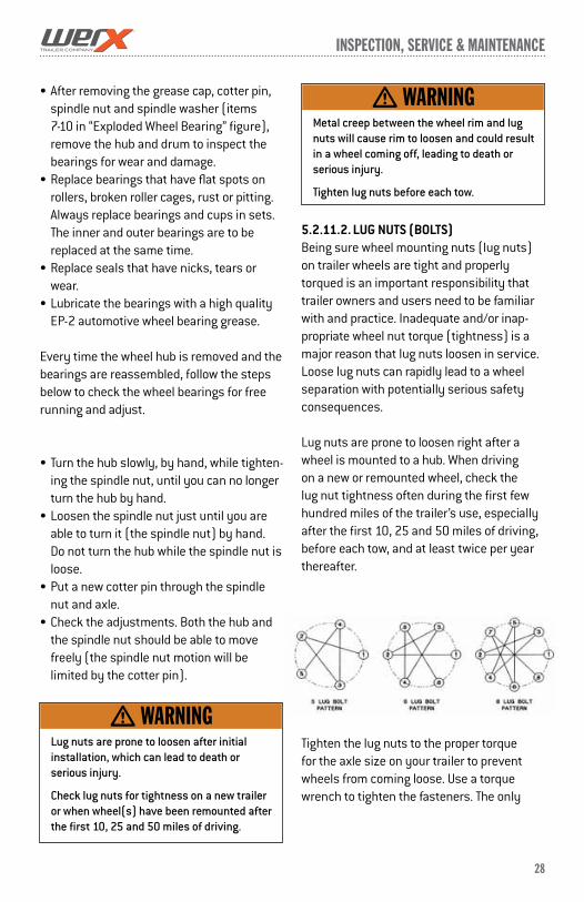
28
inspecTion, service & mainTenance
After removing the grease cap, cotter pin, spindle nut and spindle washer (items 7-10 in “Exploded Wheel Bearing” figure), remove the hub and drum to inspect the bearings for wear and damage.
Replace bearings that have flat spots on rollers, broken roller cages, rust or pitting. Always replace bearings and cups in sets. The inner and outer bearings are to be replaced at the same time.
Replace seals that have nicks, tears or wear.
Lubricate the bearings with a high quality EP-2 automotive wheel bearing grease.
Every time the wheel hub is removed and the bearings are reassembled, follow the steps below to check the wheel bearings for free running and adjust.
Turn the hub slowly, by hand, while tighten-ing the spindle nut, until you can no longer turn the hub by hand.
Loosen the spindle nut just until you are able to turn it (the spindle nut) by hand. Do not turn the hub while the spindle nut is loose.
Put a new cotter pin through the spindle nut and axle.
Check the adjustments. Both the hub and the spindle nut should be able to move freely (the spindle nut motion will be limited by the cotter pin).
5.2.11.2. LUG NUTS (BOLTS)Being sure wheel mounting nuts (lug nuts) on trailer wheels are tight and properly torqued is an important responsibility that trailer owners and users need to be familiar with and practice. Inadequate and/or inap-propriate wheel nut torque (tightness) is a major reason that lug nuts loosen in service. Loose lug nuts can rapidly lead to a wheel separation with potentially serious safety consequences.
Lug nuts are prone to loosen right after a wheel is mounted to a hub. When driving on a new or remounted wheel, check the lug nut tightness often during the first few hundred miles of the trailer’s use, especially after the first 10, 25 and 50 miles of driving, before each tow, and at least twice per year thereafter.
Tighten the lug nuts to the proper torque for the axle size on your trailer to prevent wheels from coming loose. Use a torque wrench to tighten the fasteners. The only
Lug nuts are prone to loosen after initial installation, which can lead to death or serious injury.
Check lug nuts for tightness on a new trailer or when wheel(s) have been remounted after the first 10, 25 and 50 miles of driving.
m WarninG
Metal creep between the wheel rim and lug nuts will cause rim to loosen and could result in a wheel coming off, leading to death or serious injury.
Tighten lug nuts before each tow.
m WarninG
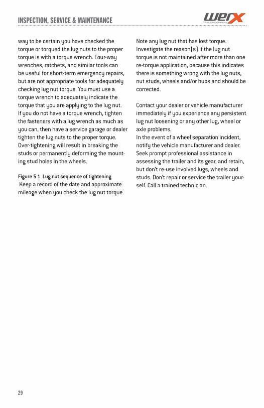
29
inspecTion, service & mainTenance
way to be certain you have checked the torque or torqued the lug nuts to the proper torque is with a torque wrench. Four-way wrenches, ratchets, and similar tools can be useful for short-term emergency repairs, but are not appropriate tools for adequately checking lug nut torque. You must use a torque wrench to adequately indicate the torque that you are applying to the lug nut. If you do not have a torque wrench, tighten the fasteners with a lug wrench as much as you can, then have a service garage or dealer tighten the lug nuts to the proper torque. Over-tightening will result in breaking the studs or permanently deforming the mount-ing stud holes in the wheels.
Figure51Lugnutsequenceoftightening Keep a record of the date and approximate mileage when you check the lug nut torque.
Note any lug nut that has lost torque. Investigate the reason(s) if the lug nut torque is not maintained after more than one re-torque application, because this indicates there is something wrong with the lug nuts, nut studs, wheels and/or hubs and should be corrected.
Contact your dealer or vehicle manufacturer immediately if you experience any persistent lug nut loosening or any other lug, wheel or axle problems.In the event of a wheel separation incident, notify the vehicle manufacturer and dealer. Seek prompt professional assistance in assessing the trailer and its gear, and retain, but don’t re-use involved lugs, wheels and studs. Don’t repair or service the trailer your-self. Call a trained technician.
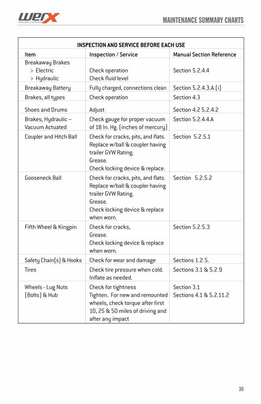
mainTenance summary cHarTs
30
INSPECTION AND SERVICE BEFORE EACH USE
Item Inspection / Service Manual Section ReferenceBreakaway Brakes > Electric Check operation Section 5.2.4.4 > Hydraulic Check fluid level
Breakaway Battery Fully charged, connections clean Section 5.2.4.3.A.(i)
Brakes, all types Check operation Section 4.3
Shoes and Drums Adjust Section 4.2 5.2.4.2
Brakes, Hydraulic – Check gauge for proper vacuum Section 5.2.4.4.AVacuum Actuated of 18 In. Hg. (inches of mercury)
Coupler and Hitch Ball Check for cracks, pits, and flats. Section 5.2.5.1 Replace w/ball & coupler having trailer GVW Rating. Grease. Check locking device & replace.
Gooseneck Ball Check for cracks, pits, and flats. Section 5.2.5.2 Replace w/ball & coupler having trailer GVW Rating. Grease. Check locking device & replace when worn.
Fifth Wheel & Kingpin Check for cracks, Section 5.2.5.3 Grease. Check locking device & replace when worn.
Safety Chain(s) & Hooks Check for wear and damage Sections 1.2.5.
Tires Check tire pressure when cold. Sections 3.1 & 5.2.9 Inflate as needed.
Wheels - Lug Nuts Check for tightness Section 3.1(Bolts) & Hub Tighten. For new and remounted Sections 4.1 & 5.2.11.2 wheels, check torque after first 10, 25 & 50 miles of driving and after any impact
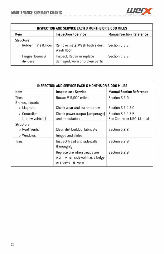
mainTenance summary cHarTs
31
INSPECTION AND SERVICE EACH 3 MONTHS OR 3,000 MILES
Item Inspection / Service Manual Section Reference
Structure > Rubber mats & floor Remove mats. Wash both sides. Section 5.2.2 Wash floor
> Hinges, Doors & Inspect. Repair or replace Section 5.2.2 dividers damaged, worn or broken parts
INSPECTION AND SERVICE EACH 6 MONTHS OR 6,000 MILES
Item Inspection / Service Manual Section Reference
Tires Rotate @ 5,000 miles Section 5.2.9Brakes, electric > Magnets Check wear and current draw Section 5.2.4.3.C
> Controller Check power output (amperage) Section 5.2.4.3.B (in tow vehicle) and modulation See Controller Mfr’s Manual
Structure > Roof Vents Clean dirt buildup, lubricate Section 5.2.2
> Windows hinges and slides
Tires Inspect tread and sidewalls Section 5.2.9 thoroughly.
Replace tire when treads are Section 5.2.9 worn, when sidewall has a bulge, or sidewall is worn

mainTenance summary cHarTs
32
INSPECTION AND SERVICE EACH YEAR OR 12,000 MILES
Item Inspection / Service Manual Section Reference
Brakes, all types > Shoes & drums Check for scoring and wear. Section 5.2.4.1 Replace per manufacturer’s specifications See Brake Mfr’s Manual
Jack, Drop-leg Grease gears at top See Jack Mfr’s Manual
Structure > Frame members Inspect all frame members, bolts Section 5.2.4.1 & rivets. Repair or replace damaged, worn or broken parts.
> Welds Inspect all welds. Repair as needed Section 5.2.2.2
Wheels > Sealed Bearings Check and confirm free running. Section 5.2.11 (Hubs) Replace if not (sealed bearings are not serviceable)
> UNSEALED Bearings Disassemble/inspect/assemble Section 5.2.11.1 (Hubs) and repack. Replace promptly See Axle Mfr’s Manual if immersed in water
> Rims Inspect for cracks & dents. Section 5.2.10 Replace as needed.
Structure
> Axle Attachment Check BY DEALER Section 5.2.1 Bolts
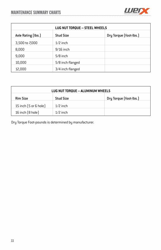
33
mainTenance summary cHarTs
LUG NUT TORQUE – STEEL WHEELS
Axle Rating (lbs.) Stud Size Dry Torque (foot-lbs.)
3,500 to 7,000 1/2 inch
8,000 9/16 inch
9,000 5/8 inch
10,000 5/8 inch flanged
12,000 3/4 inch flanged
LUG NUT TORQUE – ALUMINUM WHEELS
Rim Size Stud Size Dry Torque (foot-lbs.)
15 inch (5 or 6 hole) 1/2 inch
16 inch (8 hole) 1/2 inch
Dry Torque Foot-pounds is determined by manufacturer.

WirinG DiaGrams
34
TOW VEHICLE WIRINGTow vehicles must have the correct plug at the rear and be connected to the correct tow vehicle circuits using acceptable practices in wire routing and connections.
An important thing to incorporate into tow vehicle wiring is the ground wire running from the plug back to the frame of the tow vehicle. Safety chains, hitches, couplers, and load leveling equalizer bars will NOT provide an adequate continuous ground and is the cause of many electrical failures.
4-WAY WIRING DIAGRAM
7-WAY PLUG DIAGRAM
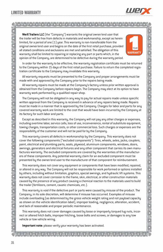
35
limiTeD WarranTy
WerX Trailers LLC (the “Company”) warrants the original owner/end user that the trailer will be free from defects in materials and workmanship, except as herein limited, for a period of one (1) year. This warranty is non-transferable from the original owner/end user and begins on the date of the first retail purchase, provided all stated conditions and exclusions are met and satisfied. The obligation of this warranty shall be limited to repairing or replacing any part or parts which, in the opinion of the Company, are determined to be defective during the warranty period.
In order for the warranty to be effective, the warranty registration certificate must be returned to the Company within 15 days of the first retail purchase. Failure to return the completed regis-tration certificate to the Company may invalidate this warranty.
All warranty requests must be presented to the Company and proper arrangements must be made with and approved by the Company prior to the repairs being made.
All warranty repairs must be made at the Company’s factory unless prior written approval is obtained from the Company before repairs begin. The Company may elect at its option to have warranty work performed by a qualified repair shop.
The Company will not be obligated in any way to pay for actual repairs made unless specific written approval from the Company is received in advance of any repairs being made. Repairs must be made in a manner that is approved by the Company. Charges for labor and parts for any covered warranty work are limited to the cost that would have been incurred by the Company at its factory for such labor and parts.
Except as described in this warranty, the Company will not pay any other charges or expenses, including overtime labor, service calls, loss of use, inconvenience, rental of substitute equipment, towing charges, transportation costs, or other commercial loss. Such charges or expenses are the responsibility of the customer and will not be paid for by the Company.
This warranty covers all defects in workmanship by the Company. This warranty does not cover the following components (“excluded components”): Tires, wheels, axles, jacks, couplers, paint, electrical and plumbing parts, seals, plywood, aluminum components, windows, doors, awnings, generators and electrical fixtures and any other component that carries its own manu-factures warranty. The excluded components are covered by the warranties of the manufactur-ers of these components. Any potential warranty claim for an excluded component must be presented by the owner/end user to the manufacturer of that component for reimbursement.
This warranty does not cover any equipment or components that have been modified, repaired, or altered in any way. The Company will not be responsible for work performed or options installed by others, including without limitation, graphics, special awnings, and hydraulic lift systems. This warranty does not cover corrosion to the frame, skin, electrical, or other construction materials caused by the presence of any product causing a chemical reaction to the materials used to build the trailer (fertilizers, cement, caustic chemicals, etc.).
This warranty is void if the defective part or parts were caused by misuse of the product. The Company, in its sole discretion, will determine if misuse has occurred. Examples of misuse include overloading (as determined by the gross vehicle weight rating and not payload capacity as shown on the vehicle identification label), improper loading, negligence, alteration, accident, and lack of reasonable and proper periodic maintenance.
This warranty does not cover damages caused by loose or improperly torqued lug nuts, incor-rect or altered hitch balls, improper hitching, loose bolts and screws, or damages to any tow vehicle or tow vehicle wiring.
Important note: please verify your warranty has been activated.
1 YEAR
WARRANTY
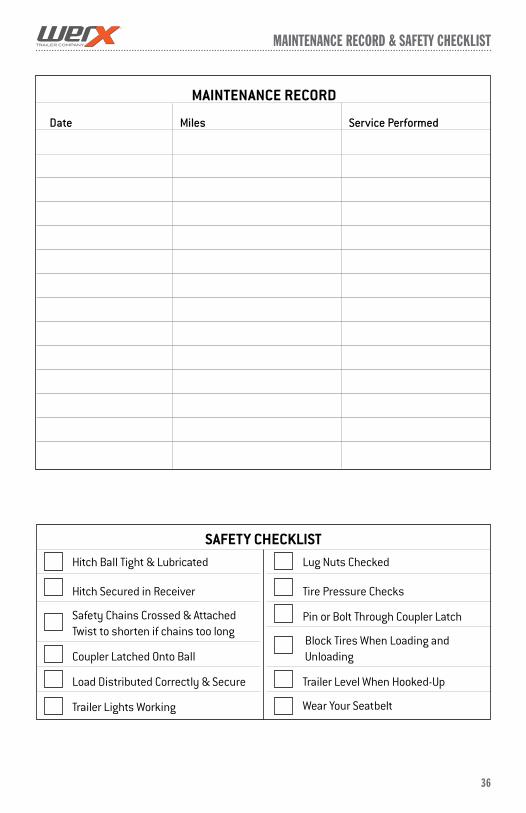
mainTenance recorD & safeTy cHecKlisT
36
MAINTENANCE RECORD
Date Miles Service Performed
Hitch Ball Tight & Lubricated
Hitch Secured in Receiver
Safety Chains Crossed & Attached Twist to shorten if chains too long
Coupler Latched Onto Ball
Load Distributed Correctly & Secure
Trailer Lights Working
Lug Nuts Checked
Tire Pressure Checks
Pin or Bolt Through Coupler Latch
Block Tires When Loading and Unloading
Trailer Level When Hooked-Up
Wear Your Seatbelt
SAFETY CHECKLIST

DuEtOCOntinuOuSPRODuCt,FEAtuREAnDSERviCEiMPROvEMEntS;StAnDARDFEAtuRES,OPtiOnALACCESSORiESAnDSPECiFiCAtiOnSSuBjECttOChAngEwithOutnOtiCEOROBLigAtiOn.CAPACitiESAREAPPROxiMAtEAnDDiMEnSiOnSAREnOMinAL.wEightSPECiFiCAtiOnSAREBASEDOnStAnDARDMODELSAnDDOnOtinCLuDEOPtiOnALEquiP-MEnt.PRODuCtPhOtOgRAPhy,iLLuStRAtiOnSORChARtSMAyShOwEquiPMEntAnDDAtAthAtiSAvAiLABLEAtAnADDitiOnALCOSt.wERxtRAiLERS,LLCRESERvESthERighttOMAKEChAngEStOPRiCESAnDMODELS,ALOngwithDiSCOntinuingMODELSwithOutnOtiCEOROBLigAtiOn.
werxtrailers.com
TM

![CARGOPRO TRAILERS [BRAND CATALOG] · PDF filecargopro contents [contents] 02 sprint utility trailers 3 standard utility trailers 4 landscape utility trailers 5 hd deckover utility](https://img.pdfslide.us/doc/110x75/5a785d9c7f8b9a77438bd82f/cargopro-trailers-brand-catalog-cargopro-contents-contents-02-sprint.jpg)